
Dual Case Instructions How to Assemble a Dual Case Adapter
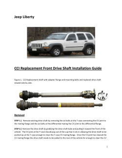
Dual Case Instructions
How to Assemble a Dual Case Adapter
Written by 4RnrRick and Wheelie_Pete
Please Note: This installer uses a rather old version of our
Successful MC07 Adapter Plate. The Instructions are
however fully compatiable with our Updated Adapter Plates.
Tools Required:
12mm, 14mm, and 30mm sockets
Ratchet and Breaker Bar
Adjustable wrench
Dead Blow Hammer (rubber mallet)
Regular Hammer
Small Magnet
3/16 Diameter Punch
Snap Ring Pliers (large and small)
6mm Allen Wrench
Gasket Scraper and/or Cleaner
Access to a Press
A good buddy comes in very handy ;-)
Crawler Installation Kit from Marlin Crawler (MC07 or better
recommend). Note: Speedometer extension isn't included in the kit. It
is an optional accessory you may need to purchase when installing a
dual crawler in 1984 and later vehicles.
Old Version MC07
A Donor Toyota Mini Truck Gear Driven Transfer Case. Note: The donor
case that is being turned into the crawl box in this example is from a
1985 remote, or forward shifting transmission (G-52). You must make
your crawl box out of whatever style will fit your existing transmission.
HOWEVER, you must use a top shifting reduction box for your rearmost case. (Forward shift to Top shift conversion kits available from
Marlin Crawler)
Disassembly of donor transfer case:
Shift case in to 4wd high range. (Both shift rods extended all the way
forward. If you forgot to shift into 4-hi before removing the transfer
case you can just pull the rods forward by hand.)
Remove rear output flange nut using a 30mm socket. This is easily
done with an impact wrench. If you don’t have an impact you can use a
couple driveline bolts through the flange and a pry bar to hold the
flange from rotating while you are using a breaker bar with the 30mm
socket. Remove Nut, Washer and Flange. Note you do not need to
remove the front output flange, just the rear.
Remove the (10) rear facing 14mm bolts (the ones with the number 6
on them) that hold the rear split case together. There is no need to
remove the (7) double notch bolts that hold on the tear drop rear
output cover.
Once the (10) bolts are removed, it should look like this.
With a dead blow hammer lightly tap on the 3 cast tabs to split the rear
case.
Slowly and carefully remove the rear case and set to the side.
Slide the Speedo Gear off the main shaft and be careful not to loose the
1/4” dia. detent ball. This ball can be removed from the shaft using a
small magnet.
Slide the Oil slinger gear off the main shaft.
Remove the rear main shaft bearing.
Remove 2wd-4wd Shift Hub.
If you look at the Shift fork you will notice that the 3/16 diameter
spring roll pin that holds the fork to the shaft is not accessible.
Shift the passenger side shift fork backward (to 2wd high) to expose
this 3/16 diameter roll pin.
Remove the 3/16 dia roll pin from the shift fork using a small punch
and a hammer. Be careful not to loose the pin in the case. You don't
have to drive the pin all the way out, just enough to slide the shift fork
off the shift rod will do at this time.
Slide the 2wd-4wd shift fork off the passenger side shift rod, the shift
collar will also now be able to be removed with the shift fork.
Now you can slide off the front wheel drive gear from the main shaft.
Be careful not to loose the second 1/4” dia. detent ball.
Note there will be (2) needle roller bearings on the ID (Inside
Diameter) of the front wheel drive gear and a thrust washer behind
that.
Remove the (2) stamped steel oil galleys. Observe and remember how
they were installed.
Remove the (4) 12mm (??) double notch bolts that hold on the cast
retainer and set the retainer to the side.
Remove large snap ring on OD (Outside Diameter) of 6308 bearing.
Remove the (2) shift detent plugs using a 6mm allen wrench. (If the
hex head holes are packed with dirt clean them out so you can get a
good grip with the hex wrench or you run the risk of stripping the holes
out.)
Using a small magnet remove the spring and 5/16" ball bearing from
the driver side.
Using a small magnet remove the spring and 5/16" ball bearing from
the passenger side.
Remove passenger side shift rod. You may need to turn it 90 degrees
(quarter turn) as you pull it out if the interlock pin is trying to hold it in
place.
Now that the passenger side shift rod has been removed, you can now
remove the shift interlock pin (its pill shaped) that is between the two
shift rods. You will need to use a magnet in the passenger side detent
hole if it didn’t already fall out.
Here's a virtual view of how the shift rods, detent balls, springs, and
shift interlok pin are assembled in the reduction box.
Now you can remove the remaining (2) 14 mm bolts (the ones with the
number 6 on them) that are rear facing.
Turn the case around and remove the last (2) 14 mm bolts (the ones
with the number 6 on them) that are forward facing (next to the front
output flange). TIP: These two bolts are often the cause of an annoying
leak in the transfer case. Many transfer cases came with a stone shield
around the CV joint on the front driveshaft. If you remove the CV shield
bracket these two bolts which the shield was mounted to will be too
long and will bottom out before they clamp the case halves together
tightly enough to prevent a leak. You either need to shorten the bolts
or just run a washer under each bolt head to make up for the missing
thickness of the stone shield bracket.
With a dead blow hammer lightly tab on the cast tabs to split the rear
housing from the reduction box. Slowly and carefully remove the rear
housing.
Set the reduction box to the side.
Removing factory main shaft:
With a dead blow hammer very carefully tap while supporting what’s
left of the main shaft assembly out of the rear housing.
Set the rear housing to the side since you will no longer need it.
Remove the small snap ring from the main shaft that holds on the 6308
bearing.
Using a bearing splitter and a press carefully press off the 6308 while
supporting the 11” long main shaft and the 37 tooth (2.28) low range
main gear.
Here's the setup that we use with the Harbor Freight 20-ton press.
Remove the 6308 bearing and thrust washer and the third 1/4" ball
bearing.
Remove the main gear (finally) and needle bearing from the main shaft.
The main gear is what you need for the crawler, so you can set the rest
to the side.
Welding the 'Keystock' to the Shift Fork:
Now is a good time to deal with the shift rod. Depending on what tranny you have, you may
need to convert the crawler to have the correct shift rod for the tranny that its going behind.
The forward reduction box (crawler box) may be top shifted or remote shifted as long as the
tranny that its going behind is a remote shifting tranny. The rear box must be a top shifting
case. For our application we need to convert our donor box to a short shift rod since it was
going behind a remote shifting W56. And the rear transfer case we acquired a top shifting case
that was behind a top shifting W56. The folks at Marlin Crawler can help you determine what
you need if your not sure.
Remove the (4) 12 mm bolts that hold the reduction box cover plate
on. (This is where your transfer case shifter would be if you have a top
shifting case from an 85-88 EFI W56 tranny.) (We forgot to take a
picture earlier so this is an "after-the-fact-to-illustrate-what-to-do" pic.
Notice the whole thing is assembled...)
Shift driver side fork so you can see the 3/16 roll pin that is holding the
shift fork onto the shift rod. With a 3/16 punch carefully punch out the
roll pin. Try not to loose it in the case. If you do drop it, remember to
get it later.
Slide the shift fork of the rail and remove the driver side shift rail and
replace with the correct one if necessary depending on your application.
There are two lengths of remote shifting shift rods. The picture shows
how the shorter 1990 W56 remote shifting t-case fork (top) compares
to the longer 1985 G52/G54 remote shifting t-case fork (bottom). In
our install we swapped out a remote shifting G52 tranny for a rebuilt
remote shifting 1990 W56. Even though both cases were remote
shifting we had to swap these shift rods to get the 1985 transfer case
shifter to work properly with the 1990 W56 transmission. (Shift rod
lengths changed in 1989 due to transmission changes, but all shift rods
are swappable between all transfer cases from 1979-1995) With a quick
call to Marlin Crawler, we got the appropriate rod.
Weld the supplied piece of ‘keystock’ across the ends of the shifter. Be
sure to clean the ‘dingle-berries’ off before reinstalling it. Also test fit
the shifter back into the newly created ‘box’ to make sure it fits where
you welded the keystock onto the shift rod.
A small piece of scrap steel (1/4” keystock) can be used in place of the
supplied piece as long as the shifter can fit into the “boxed” area and it
doesn’t interfere with the gears or the case in the reduction box.
Slide the shift rod back thru the case and the shift fork and reinstall
3/16” pin thru the fork. (This is the same picture as shown earlier for
removing the pin so pretend the keystock is welded onto the fork in the
picture.)
Reinstall the (4) 12 mm bolts that holds the shift plate on. (we where
able to reuse the factory gasket)
Assembly of Crawler:
Now that you got the main 37 tooth (2.28) low range main gear off the
main shaft you can start assembly the crawler. (The picture shows the
complete main shaft with the 6308 bearing and low range main shaft
gear still attached and needing to be removed.)
Apply a light coat of gear oil onto the new main output shaft and slide
on the 31 needle roller bearing and main 37 tooth (2.28) low range
main shaft gear which you removed from your stock main shaft.
Place one of the 1/4" dia. detent balls from the donor case in the hole
on the new main shaft and slide the new thrust washer on while
aligning the detent ball to the slot in the thrust washer.
Now very carefully install the new main shaft assembly from above into
the pre-installed bearing in the MC07 Crawler adapter.
Install the new large heavy duty retaining ring on to the end of the new
main shaft.
We broke one set of snap ring pliers and it took a lot of fiddling but we
finally got it. Basically I would recommend a GOOD HEAVY DUTY set of
snap ring pliers and an extra set of hands to install this snap ring
because it takes a good amount of force to spread the new heavy duty
snap ring over the shaft.
Then we very lightly tapped the main shaft to seat the retaining ring
against the bearing so we could properly check the main gear oil
clearance gap.
Then we check the oil clearance gap between the main 37 tooth (2.28)
low range main gear and the end of the main shaft. It should be
between .004” and .010”. Ours was .006” so we continued.
Now install (5) of the (11) studs into the reduction box with the short
threaded end into the reduction box. If you don’t have a stud
installation tool, double nutting with the supplied 14 mm bolts works
just fine. We also used blue loc-tite on these studs to prevent problems
in the future. Tip: To install studs using the double nut method simply
run one nut down the threads, then bring another nut down on top of
the first. Tighten them to EACH OTHER, then turn the stud into the hole
using the TOP nut. When you have torque the stud in tight, simply turn
the lower nut down the remaining stud threads. This will break it loose
from the upper nut, but not loosen the stud. Note: There will be one
threaded hole in top center of the reduction box that you do not install
a stud in due to the adapter plate covering the hole. Just hold the
adapter plate up to the back of the reduction box before you puts studs
in to verify where the studs are to be replaced.
Now pack the 8 needle roller bearing with grease and install on the
reduction box main shaft.
Clean the mating surfaces and spread a thin layer of your favorite
sealant (Permatex Ultra Black is what I like) on the reduction box
mating surface. Now very carefully align the crawler adapter assembly
onto the reduction box. This may take a bit of time to align the shafts
and gears to get it to slide on. Eventually it will slide on.
Now install the supplied washer, lock washer and nut on each of the
five studs and tighten. Reuse (2) of the original 14 mm bolts (the ones
with the number 6 on them) and install in the two extra hole to finish
the main assembly.
Reuse the drain plug from the donor case and install into the bottom of
the adapter. (oil the tread to prevent future galling. We decided to
install one of the low profile drain plugs here.
Reinstall the 5/16" dia. shift rod ball, detent spring and plug into the
side of the adapter. We applied some sealant (Ultra Black) onto the
thread to seal it.
Remove the 4wd shift position indicator from the reduction box.
Now install the seal and plug that is provided in the kit to seal the 4wd
shift position indicator hole.
That completes the assembly of the crawler. Remove the old
transmission seal, install the new supplied transmission seal, install the
new supplied paper gasket using "Hi-Tack" (black berry jam) or your
favorite sealer, and bolt the reduction box and crawler adapter to the
back of your transmission.
Preparation of Rear Transfercase
This article is specifically about assembling the crawler. If you got this far putting the back end
on should be painfully easy. But, just for giggles, here's the other stuff you will need to do
before you can wheel.
If your rear-most case came out from behind a 1979 or 1980 4 speed, you will need need to
grind the flared spline area on the main 21 spline input shaft so it will flush up with your
crawler. Search Pirate4x4 or contact Marlin. This is kinda rare, but does crop up from time to
time. www.MarlinCralwer.com
If your rear-most case is out of a 1985 to 1988 top shifting EFI (W56-A/B) tranny
then you must shorten the driver's side shift rod. This is the shift rod sticking out of
the rear most case when you shift into 4hi that has the flat side on top. You must
trim 1/2" off of the front of this shift rod to avoid jamming between the two cases.
Install final (6) studs into transfer case
Check operation of transfercase
Lengthen 4wd shift indicator light wire.
Install Speedo Extension if needed for your application (1984 and later)
Modify floorboard, driveline length, crossmember and add 3 quarts of oil [80-90wt.GL5 gear
oil] (2) for the transfer case (1) for the new crawl box, as per Marlin's instructions.
Don't forget to re-fill your tranny if you drained it!
That completes the assembly of your Marlin Crawler Dual Adapter
www.MarlinCralwer.com (559) 252-7295
All Content Copyright Marlin Crawler 2007. All products intended for off-road use. All products guaranteed for
one year against defects in materials and labor. Prices and products subject to change without notice.


© Copyright 2026