
HOW TO MATCH PUMPING SPEED TO GAS LOAD From
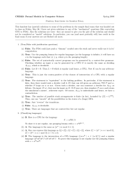
A Journal of
Practical and Useful
Vacuum Technology
From
By Phil Danielson
HOW TO MATCH PUMPING SPEED TO GAS LOAD
Pumping speed is one of the triumvirate of quantities that make up the
fundamental relationship that governs the behavior of all vacuum
systems. This relationship, written as Q (gas load) = S (pumping speed)
x P (pressure), should be constantly in the forefront of the mind of every
vacuum technologist. Achieving and maintaining the pressure required
by the process will be dependent upon the matching of the gas loads
and the pumping speed. Once a system’s gas loads have been
assessed, the pumping speed requirements need to be considered if the
process specifications are to be met. Additionally, in terms of existing
systems, the same process will help in understanding the system’s
performance and aid in trouble-shooting when possible performance
problems are encountered.
Although the Q=SP relationship is pretty handy, a certain amount of
confusion can ensue if you don’t stop to realize that Q (gas load) and
S (pumping speed) are two different ways of defining gas flow. Gas load
is referred to as mass flow while pumping speed is referred to as volume
flow. This clears up a little if you think of mass flow as the total number
of molecules that a pump has to deal with and volume flow as the
volume of gas a pump can inhale at a given pressure where you think of
pressure as the population of molecules per unit volume. If you look at a
manufacturer’s data sheet for a given pump, you’ll see that the pumping
speed specification is given in volume per time such as cubic
feet/minute or liters/second. It’s really as simple as that, but if you don’t
keep the difference between the two types of flow in mind when
numbers are being thrown around, you can end up with a lot of
confusion.
Any pump manufacturer is faced with the need to differentiate one
pump, of the same type, from another. This is both logically and
traditionally done by pumping speed so that a potential customer can
zero in on the particular model pump that best suits the application at
hand. Although this is probably the most reasonable system of
differentiation, a potential danger lurks quietly here for the user. That is,
the very differentiation system can generate a misunderstanding which
can easily lead, in turn, to a misapplication. Once a number is stated, it
tends to get mentally locked in. If, say, a pump is listed as having a
nominal pumping speed of 1,000 liters/sec., there’s a tendency to
continue using that number for subsequent thinking and calculation.
Three separate considerations then come into play and wave a caution
flag:
1. Most pumps have pumping speeds that vary with pressure,
2. Most pumps will pump different gases at different speeds, and
3. The speed of the pump itself is seldom the realized pumping
speed at the system’s chamber.
If all three of these considerations aren’t taken into account, you can
easily end up with the wrong pump in the wrong installation and a very
wrong system performance. Attempting to make a Q=SP calculation with
the wrong numbers for a particular application can be an application
disaster. For fuller understanding, these three considerations need to be
discussed separately.
% Pumping Speed
The nominal pumping speed listed by most manufacturers’ literature is
a pump’s maximum speed. This might, at first glance, seem to be mere
sales hype, but it makes sense. You’d want to choose a pump that
would have its maximum speed at the pressure where you needed the
speed for your application. Since it’s the usual practice, maximum speed
specifications make as much sense as any other. In most literature,
you’ll also find a pumping speed vs pressure curve. This curve is
immensely useful because it describes the pump’s performance
throughout its probable application range. If, for example, you look at the
curves for most positive displacement roughing pumps, you’ll see that
the highest speed is shown at atmospheric pressure, but that the speed
declines precipitously as
Relative Pumping Speeds
the pump begins to
110
achieve
its
l o we s t
Cryo
100
attainable pressure. If the
Diaphragm
pump is intended to serve
90
as a roughing/backing
80
pump for a turbo-pumped
Mechanical
70
system, the pumping
60
speed
curve
would
provide
the
crucial
50
Turbo
information that would tell
40
you if it had enough
30
pumping
speed
to
adequately support the
20
Ion
turbo pump and handle
10
the amount of gas flowing
0
out of the turbo’s exhaust.
10 -8 10 -7 10 -6 10 -5 10 -4 10 -3 10 -2 10 -1 10 0 10 1 10 2 10 3
Other
important
torr
information to be gleaned
The relative pumping speed changes with pressure for common
from the pumping speed
vacuum pumps.
vs p r e s s u r e curve(s)
would be to ascertain whether a given pump could meet and maintain a
specified pressure at a specified process gas flow adequately. The importance of these curves becomes plainer when it’s necessary to compare one manufacturer’s pumps to another. The shape of the curve can
easily help make the decision when specific speeds at specific pressures are important to the process. Pumping speed vs pressure curves
can be even more important when high vacuum pumps are considered.
While roughing pump speeds tend to drop off as the pressure drops,
most high vacuum pumps, with the notable exception of cryopumps,
have speeds that increase as the pressure is lowered until they level off
at some maximum speed.
Since a vacuum process involves both pumping a chamber down and
maintaining a given pressure during a process, it’s vital that the pumping
speeds of both the roughing and high vacuum pumps are carefully
matched to the chamber volume, desorption, and process gas loads.
The pumping speed of a given pump for various specific gases becomes
most important when comparing high vacuum pumps. Again, a
manufacturer’s pumping speed rating can be misleading. The pumping
speed rating is usually provided, in an overall differentiation sense, for
air or nitrogen. This is both logical and useful, but the potential user
needs to interpret this specification in light of the particular application.
During a pumpdown cycle from atmospheric pressure, for example, the
high vacuum pump will probably never be called upon to pump air to a
great extent. Consider that the gas load, during a pumpdown, below 1
millitorr or so will be almost entirely water vapor desorbing from O-rings
and from the chamber’s surfaces. Although comparing nitrogen pumping
speeds from pump to pump is useful, it’s even more important, at this
point, to begin to compare water vapor pumping speeds. For example, a
cryopump will have a much higher water vapor speed than a
turbomolecular pump even though both pumps might have exactly the
same nitrogen speed.
Obviously, pumping speed is not the only thing to be considered when
choosing the type of pump to be used, but it cannot be ignored either.
The same thinking must be used when choosing the manufacturer of a
given type of pump. A turbo pump for a helium leak detector provides a
good example. In this case, the pumping speed for helium is a key
requirement since it’s necessary to pump away a sudden helium gas
load engendered by a leak. Turbo pumps have low helium speeds
relative to their nitrogen speeds, and different designs have different
helium speeds relative to their nitrogen speeds. In this case, the choice
would probably be made to favor the manufacturer with the highest
helium pumping speed. The same can be said of any process gas load
that needs to be either removed or maintained at a given pressure
during the process.
The effective pumping speed provided to the chamber is not completely
a function of the pump’s actual rated speed. The plumbing connecting
the pump to the chamber can be even more important. This is especially
true in the molecular flow regime. In molecular flow, the gas molecules
are moving randomly with almost no molecule-to-molecule collisions.
This means that they will only reach the pump statistically and will not be
driven by pressure differential. Calculating the performance of a system,
then, has to take into account the type of flow, the speed of the pump,
and the connecting plumbing or tubulation. The expected gas flow
through the tubulation is a function of both the diameter and length of
the tubulation and is referred to as conductance. Conductance is usually
given in liters/second so it is volume flow.
Calculating the effective pumping speed can be complicated, but a
practical method is available that’s fairly straightforward. Roughing
pumps, operating mostly in viscous flow conditions are the easiest to
deal with by using the conductance(C) formula:
C in liters/sec. = F x (avg. pressure in torr x diameter4/ length)
F= 2,950 for inches or 180 for centimeters
The effective pumping speed is then calculated by this formula:
Effective Speed in liters/sec.= 1/((1/Sp) +(1/C))
where Sp is the rated speed of the pump in liters/sec.
Calculating the effective pumping speed in the molecular flow regime2
can be a good deal more complicated, but in a well designed system
where the connecting tubulation is short, the same diameter as the
pump, and the same diameter from chamber to pump a simple method
is to use the following system. This method uses the conductance of the
pumping line’s entry orifice and the transmission probability of molecules
down the line to the pump.
Maximum Orifice Conductance(COrifice) in liters/sec.
Gas
H2
He
H20
N2
Air
O2
A
Xe
l/sec/cm2
44.01
31.23
14.72
11.81
11.61
11.05
9.89
5.45
l/sec/in.2
283.9
201.4
94.9
76.1
76.1
71.3
63.8
35.2
The conductance of the tube is C (liters/sec) = Corifice x a
Where a(transmission probability) is calculated from the formula;
a= 1/ 1+(L/D) x ((3L/D + 10)/(4L/D) + 10))
where length(L) and diameter(D) cab be in any units as long as they are
consistent since a is based on ratios.
Once the conductance of the pumping line is calculated, the same
formula for effective pumping speed as shown above can be used.
A clear knowledge of a system’s as loads and pumping speed can be
the basic key to understanding its performance. The simple Q =SP
calculation can then allow predictions of performance to be made during
both the design stage of a new system and the ongoing surveillance of
an existing system.
References
1. “Assessing Gas Loads in Vacuum System Design”, R&D, Oct.,2000 ,pg 39-40
2.”Calculation of Pumping Speeds of High Vacuum Systems in Molecular Flow,” G.S.
Ash, Soc. Vacuum Coaters, 37th Annual Technical Conference Proceedings, (1994),
pg 100-109. Reprints available from [email protected] or 508-3375130.
Reprinted with permission by R&D Magazine. All rights reserved. Copyright 2000.
Cahners Business Information.
A shorter version appeared in R&D Magazine, December 2000.
From The Vacuum Lab of Phil Danielson, 630-983-2674
[email protected]
www.vacuumlab.com


© Copyright 2026