
How to use ROGER GPS Repeater and accessories.
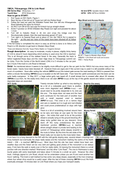
How to use ROGER GPS Repeater and accessories.
ROGER™ GPS repeater installation instructions
2...Index
3...Product description
3...Declaration of conformity
4...Company and contact informations
5...ROGER GPS Repeater Package (GPSR-BP)
6...ROGER GPS Repeater, controls and connectors
7...Technical information
8-9...GPS repeater installation
10...Troubleshooting
11...Splitter and Amplifier Installation instructions
11...ROGER GPS Amplifier (GPSR-A)
12...ROGER GPS Splitter (GPSR-S)
13... ROGER GPS Amplifier&Splitter (GPSR-AS)
14... What to consider when planning a ROGER GPS Repeater installation
15... Example of link loss budget
2.
Product description
ROGER GPS repeater operates by receiving GPS satellite signals with an antenna
located outside the building and re-radiating the signals to the indoor area or
covered space.
Use of re-radiated signals means that GPS receiver is tracking the current GPS status
meaning that when a GPS receiver is moved from covered area to outdoors, the
receiver is instantly tracking the location instead of time consuming acquisition of
GPS data.
Please note that ROGER GPS repeater cannot be used for indoor navigation since
the receiver will always give the position of the outdoor antenna instead of the real
position.
Operating license note
Note: GPS repeaters may require a license or they may not be used in your country.
Check license conditions with the local (radio)authorities before operating the GPS
repeater product. In some countries the ROGER™ package contains instructions and
the necessary forms to obtain an operating license from the local authorities.
3.
Company
Owned by Sparklike Ltd., Roger-GPS Ltd. is a company specialized in GPS technology. Its customers include a wide range of users who need GPS signal reception
indoors. Users include rescue services, police, defence, airlines and companies
manufacturing, selling and servicing GPS terminals. Roger-GPS Ltd.’s business concept permits the use of GPS devices and services in places where it was previously
impossible.
The company was established in 2009 to carry on the development, manufacture and
marketing of GPS products started by Sparklike Ltd. In September 2008 Sparklike
Ltd. launched the first CE-certified GPS repeater and product family approved by the
communications authorities in Finland and Sweden for use as radio-licensed devices.
So far it is the only product of its type to meet the applicable standards.
The first GPS repeater users in Finland and Sweden are the fire-fighting and rescue
services. Additionally, devices have been installed in the premises of local police departments and airlines and in testing and servicing companies.
The increasing popularity of GPS terminals has generated new applications and given
rise to expectations that these devices would be able to operate indoors as well.
Contact information:
Roger-GPS Ltd.
Särkiniementie 5 C 6
FIN-00210 Helsinki
FINLAND
e-mail: [email protected]
BI: 2246514-0
4.
Products
ROGER GPS Repeater Package (GPSR-BP)
A single ROGER GPS Repeater Package is enough to provide a GPS indoor coverage
area of 30 metres in diameter from the repeater. Mount the external antenna on the
roof of the building and connect the cable (RG58), supplied with the kit, to the antenna
and to the repeater installed indoors.
Connect the power supply unit to the repeater, adjust the repeater’s transmission
power according to the local conditions, to prevent a signal loopback, and indoor
GPS coverage is immediately available. The kit includes clear installation instructions
and a pre-completed application for a radio license.
Several ROGER GPS Repeater Packages can be installed in the same building.
Alternatively, the signal coverage provided by a single package can be extended with
ROGER GPS Accessories, such as line amplifiers and signal splitters.
WHAT’S IN THE BOX
1. GPS Repeater
2. Outdoor antenna for receiving the GPS signals
3. Power supply
4. RF-cabling, 19,5m
1. GPS Repeater
The GPS repeater works by receiving GPS signals from satellites with an outdoor
antenna. The signals are then transmitted to indoors via cable and re-radiated by the
GPS repeater. The GPS Repeater is powered from mains by the power supply.
In addition, it is possible to use custom length cables and line amplifiers to extend the
cable length and signal splitters with additional transmitters to extend the coverage
area.
Since the GPS signals are very low level, the repeater incorporates special circuitry to
limit the output level to a maximum value within the requirements to conform with the
CE requirements.
2. Outside antenna
The outside antenna is used to receive GPS satellite signals. The antenna has a
female TNC connector and requires +5VDC power through the center pin. The power
is usually supplied by the repeater, but if there is a DC block in the cable used, the
power must be supplied from an another source.
Please note that a good quality antenna and a good location are essential for effective
operation of the GPS repeater system. The standard antenna supplied in the kit has
+35dB gain and <3dB noise figure.
5.
In some cases a small patch antenna may be used. Typically this kind of solution is used
in research labs where the receiveantenna can be easily located outside by the window.
The indoor coverage is typically greatly reduced in this case and feedback may present a problem (indicated by RED led indication), but is typically sufficient to bench test
handheld GPS equipment.
Hint: the location of the outside antenna can be easily located by using a GPS receiver
to read the coordinates through the repeater.
3. Power supply
The GPS Repeater system is powered by a DC wall adapter supplied in the installation
kit.
4. Cable
The standard cable supplied with the repeater is of RG58 type, which can be used for
cable runs of up to 20 meters. Cable runs up to 40 meters can be realized with RG214.
Longer cable runs may require a separate line amplifier to compensate the power loss in
the cable .
ROGER GPS Repeater, transmitter unit
The transmitter unit is the main component of the system. The GPS Repeater
transmitter contains filtering, amplifiers and power control circuits. The GPS Repeater
also supplies power (+5VDC, max 100mA) to the outdoor antenna through the antenna
cable.
ROGER GPS Repeater, controls and connectors
5. Transmitting antenna
5. Input connector
2. DC Power
1. Gain control
6.
4. Status LED
Description of GPS Repeater controls and connectors :
1.
Gain control knob
The gain control knob is used to control the output power of the
GPS repeater.
2.
DC power connector
The repeater power is supplied through the DC input connector.
The connection is reverse polarity protected. (+12VDC 300mA in)
3.
Receiving antenna connector
Receiving antenna should be connected to the SMA input
connector with the cable supplied. Alternatively, a custom cable can be used. (SMA female, +5VDC 100mA output for active antenna)
4.
Status LED
The LED of the repeater should flash a few times at startup and then turn constant red or green.
5.
Integrated antenna inside the case
Technical information
Size
Weight
Overall Gain
Noise Figure
Variable attenuation
Impedance
Input connector
Operating temperature
Power supply
Indoor coverage radius
Antenna power output
TX antenna gain
110*143*28 mm
165 g
> 40dB < 2dB
0-40dB
50Ω
SMA-female
-35 - +60°C
+12VDC, 300mA Power supply included
5-10m
+5VDC, 100mA
max +4dBd, RHCP polarization
Other features
Automatic gain control
Feedback oscillation suppression
Manual gain control
Output power limit –60dBm
Status/power LED
Internal transmit antenna
CE-certified
7.
Installation
When installing the GPS repeater, you should have:
•
a suitable tools to tighten the SMA connector
•
handheld GPS receiver (*)
•
Suitable fixing tools and accessories
(*The GPS receiver must be able to show the satellite signal levels.)
1.
2.
3.
Fast instructions
1. Open the ROGER GPS Repeater Pack.
2. Use the black mount to connect cable with TNC male connector.
3. Mount the external antenna on the roof of the building and connect the cable
(RG58), supplied with the kit, to the antenna and to the repeater installed indoors.
4. Install the GPS repeater transmitter by fixing it to ceiling, wall or a suitable mount.
5. After having installed the outside antenna, cable and repeater, plug in the wall adapter cable and plug the adapter to a power outlet.
6. The LED of the repeater should flash a few times at startup and then turn constant red or green. Adjust the repeater’s transmission power according to the local
conditions, to prevent a signal loopback, and indoor GPS coverage is immediately
available.
4.
8.
5.
6.
About installation
Receiving antenna installation
The receiving antenna should be placed in a place where it can ‘see’ as much of the
sky as possible. It should be also located as far as possible from any RF interference
sources, like any transmitting antennas. Before fixing the
antenna, check that the cable is long enough and it can be run from the
antenna to the required indoor location.
It is also recommended that the system is first tested by running the cable through
a convenient route to the indoor installation place and checking that the indoor GPS
coverage is suited to the use.
GPS repeater installation
Install the GPS repeater transmitter by fixing it to ceiling, wall or a suitable mount.
The repeater has an integrated antenna, which is located next to the status LED.
The transmitter radiates mostly towards to the same direction as the LED. Ideally the
transmitter should be located so that any desired GPS receiving location (like an antenna on top of a van in a garage) has a direct line-of-sight to the repeater antenna.
Also note the length of the wall adapter cable when planning the installation location.
After having installed the outside antenna, cable and repeater, plug in the wall adapter
cable and plug the adapter to a power outlet. The LED of the
repeater should flash a few times at startup and then turn constant red or green.
The indications of the status LED are:
•
GREEN: Transmitter is operating normally
•
Constant RED/GREEN: Transmitter is operating normally, output power has been limited to maximum allowed value.
•
RED: Transmitter has detected an error or interfering signal.
Typical reason is that the input antenna is located so that it can pick up the
signal from the transmitter and a feedback oscillation occures. Other common reason is that there is an interference source close to the receiving
antenna.
9.
Troubleshooting
GPS receiver cannot receive signals next to the repeater.
•
Check that +5VDC is present in the antenna end of the cable and in at the antenna connector of the repeater. Broken or short-circuited cable?
•
Check that repeater power is on and LED is on.
No LED indication on GPS Repeater
•
Check that +12VDC is present in the wall power adapter connector
•
Check that power is available in the wall connector where power adapter
is connected
LED turns RED and GPS coverage is lost.
•
Check that outdoor receiving antenna is in a location where it cannot
receive signals from the repeater
•
Try turning down the gain setting
•
Check that there are no interference signals close to the receiving antenna. The system is very sensitive to interference at the GPS L1 frequencies (1575.42+/-20 MHz)
Small indoor coverage radius
•
Check that outside antenna is correctly positioned
•
Check that there are no interference sources close to the receiving antenna
•
Check gain setting
•
Check the repeater positioning
•
Are there obstacles that could limit signal coverage?
•
Shorter cable run or a line amplifier can improve signal level slightly
•
Signal splitter and additional repeater units may be required to cover
a larger or obstructed areas
Figure 2: Wideband gain. NOTE: Attenuation outside the 1.575GHz passband is
typically better than –60dB. Graph indicates lower attenuation due to measurement
setup (spectrum analyzer noise floor).
10.
Splitter and Amplifier Installation instructions
ROGER™ GPS Signal Splitter and Line Amplifier provide longer cable runs and signal
splitting to several ROGER™ GPS Repeaters.
Output connector
Input connector
ROGER GPS Amplifier (GPSR-A)
ROGER™ GPS Line Amplifier is an amplifier that is used to allow for longer
cable runs and/or signal splitting to several GPS Repeaters. It has a gain of
+18dB at the GPS L1 frequency band and it includes a filter to remove unwanted
signals that may have entered the cable at somepoint.
The amplifier is powered though the output signal cable by the ROGER GPS Repeater
and also passes on DC power for the GPS receiving antenna or an another
GPS line amplifier.
TECHNICAL SPECIFICATIONS
Size
Weight
Operating temperature
Connectors
Frequency range Noise figure Impedance Power supply cable Gain 110*143*28mm
135 g
-35 - +85°C
TNC female input
TNC female output
1575.42 +/-15MHz filtered
<5dB
50Ω
The amplifier is powered though the output signal
by the ROGER GPS Repeater
+15dB
11.
ROGER GPS Splitter (GPSR-S)
ROGER GPS Signal Splitter is used to distribute GPS signal to several GPS Repeaters.
Splitter works with both GPS L1 and L2 frequency bands. It has one chaining output
and four repeater outputs. DC power is passed from the chaining output to the input
connector for GPS line amplifier and GPS receiving antenna. If the signal is to be
transmitted to fewer than five repeaters, the unused ports should be terminated.
Output connector
Output connector
Output connector
Input connector
Output / DC input
Output connector
TECHNICAL SPECIFICATIONS
Size
110*143*28mm
Weight
185 g
Operating temperature
-35 - +85°C
Connectors
TNC female input,
5 x TNC female output:
1 x -4dB with DC pass
4 x -12dB
Frequency range:
Impedance:
Power 12.
1200-1700MHz
50Ω
The splitter is powered though the output / DC input connector by the ROGER GPS Repeater
ROGER GPS Amplifier&Splitter (GPSR-AS)
ROGER GPS Signal Splitter & Amplifier is a combined signal splitter and line amplifier
with an output of +18db that can transmit to up to three separate repeater units. The
splitter & amplifier is easy to use and permits a wide range of system configurations.
Output connector
Output connector
Amplifier input
Splitter input
Output / DC input
Ampllifier output
TECHNICAL SPECIFICATIONS
Amplifier section
Size
Weight
Operating temperature
Connectors
Frequency range
Noise figure
Impedance
Gain
110*143*28mm
195 g
-35 - +85°C
TNC female input
1575.42 +/-15MHz
<3.8dB
50Ω
+18dB
TNC female output
filtered
Splitter section
Connectors
TNC female input, 3xTNC female output
1 x -4dB output with DC input
2 x -12dB output, DC blocked, for repeaters
Power supply:
The amplifier&splitter is powered though the output / DC input connector by the ROGER GPS Repeater
Frequency range:
1200-1700MHz
13.
What to consider when planning a ROGER GPS Repeater installation
1. Distance between the outdoor antenna and the repeater.
The Roger GPS repeater system needs ~ 15 dB RF gain from the antenna including cable losses for best performance. The antenna supplied with the basic repeater
package has an RF gain of 35 dB, which results in a cable loss budget of approximately -20 dB. Using an RG-58/RG-223 cable to connect the antenna therefore limits
the distance between the antenna and the repeater to ~ 30 m as the typical loss of a
RG-58 cable is ~ 0,65 dB/m @ 1575 MHz. If the distance between the outdoor
antenna and the repeater requires longer cable runs different methods can be used.
a) Use a lower loss cable.
Using RG214/RG213 cable will allow a cable run of 65 - 70 meters, as the typical
attenuation for this cable is ~ 0,3 dB/m @ 1575 MHz
b) Use a Line Amplifier to compensate cable losses.
Connecting the ROGER Line Amplifier between the antenna and the repeater provides
an additional +18dB gain, which increases the allowed cable length to 58 m with RG58/RG-223 cable and 125 m with RG214/RG213 cable. The ROGER Line Amplifier
should be placed as close as possible to the outdoor antenna and as it is powered by
the ROGER GPSR-1 repeater through the coaxial cable, no separate power
line connection is required. Two ROGER Line Amplifiers can be connected in series,
increasing the maximum cable length to ~ 180 m using RG-214/RG-213 and ~ 85 m
using RG-58/RG-223 cable.
2. Area to be covered by the repeater.
The area covered by the repeater typically has a radius of 10 - 15 m. This means that
for some installations, like in parking houses or garages, multiple repeaters will be
needed to provide the desired coverage.
In this example five repeaters and a 1:5 Signal Splitter are used to cover the area of a
garage. The ROGER Signal Splitter allows up to 5 repeaters to be connected to one
receive antenna. One splitter output is DC-coupled, has -4 dB coupling loss and must
always be connected to a repeater to allow DC to be fed to the receive antenna and /
or line amplifier. The four remaining outputs are DC-blocked, have -12 dB coupling
loss and should be terminated if not used. To cover bigger areas, additional signal
splitters can be connected in a chain configuration using the DC-coupled output.
Important!
In applications using multiple repeaters, the loss budget for each repeater must be
calculated to make sure – 20 dB of link loss is not exceeded.
14.
Example of link loss budget
Antenna to Line Amplifier loss, 1.5 m of RG-58 cable: Line Amplifier gain: Line amplifier to Splitter loss, 40 m RG-213: Splitter coupling loss: Splitter to repeater loss, 10 m RG-58: - 2 dB
+18 dB
- 13 dB
- 12 dB
- 7 dB
TOTAL Link (antenna to repeater) loss: - 16 dB
Even if the low loss RG-214/RG-213 cable is higher cost than RG-58/RG-223, if it’s
only a question of increasing the distance between the outdoor antenna and a single
repeater, using a low loss RG-214 cable will be more economical than adding a Line
Amplifier. However, if a Signal Splitter is used to allow more than one repeater
sharing the same outdoor antenna, most applications will require a Line Amplifier
to be used.
15.
www.gps-repeating.com


© Copyright 2026