
Document 225910
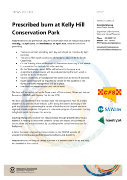
J
How to Develop a
TaIL Bum Plan
RCRA requires
that new afilicants
for hazardous waste
incinerators conduct
trial burn tests.
by Ahmed J. Allawi, P.E.
This is the first of a two-part series on
trial burn plan development for hazardous waste incinerators. Part One covers
the elements of the trial burn plan and
permit parameters for a typical hazardous waste incineration facility. Part
Two, which will appear in POLLUTION
ENGINEERING in November, discusses trial burn test design, including
development of a test protocol.
82 POLLUTION
ENGINEERING
OCTOBER1991
The Resource Conservation and Recovery Act (RCRA) of 1976 (42 U.S.C.
6901-6987, amended in 1984) requires
the Environmental Protection Agency
(EPA) to develop, promulgate and implement regulations that control the
treatment and disposal of hazardous
wastes. RCRA regulations are aimed at
ensuring the incineration system under
review meets a set of minimum performance requirements within the
range of operating conditions desired
by the owner/operator of the system.
The law requires the applicant for a
new hazardous waste incineration permit to demonstrate by actual field testing that the incineration system meets
all RCRA requirements. These field
tests are called trial burn tests.
An integral section of the Part B Permit Application for Hazardous Waste
Incineration is the Trial Burn Plan,
which the applicant is required to develop and submit to the regulatory
agencies for approval. Since the granting of the operating permit is contingent on passing the trial burn tests, it
is important that applicants address all
relevant issues when developing their
trial burn plans.
Elements of a trial burn plan
The trial burn plan is a protocol prepared by the applicant for a hazardous
waste incineration permit to outline the
test conditions and methodologies that
will be used to demonstrate the operability of the hazardous waste incinera-
tion system. The main objectives of the
trial burn tests are three-fold:
To verify that the incinerator and associated equipment can be operated
under the conditions desired by the
applicant.
To obtain data that set limits for the
operating parameters to be specified
in the permit.
To supply trial burn data required by
RCRA, the Toxic Substances Control
Act (TSCA, 15 U.S.C. 2601-2629),
state regulatory agencies and other
parties as mandated by law.
A typical incineration system can be
operated safely and efficiently under
more than one set of operating conditions. As each process variable within
the control of the operator is increased
or decreased, however, the safety and/
or performance efficiency of the total
system may be compromised. The
safety issue can only be addressed on
an individual basis for each system.
Incineration performance standards
have been established by the regulatory
agencies. The following five performance standards must be met by all new
incineration systems to be operated in
the United States:
Minimum destruction and removal
efficiency (DRE) of 99.99 percent for
the principal organic hazardous constituents (POHCs). The DRE is defined by the following equation:
DRE = (W,” - WouJ(lOO)/W,n
where W,, equals the total POHC feed
during the time period in question
and W,,, equals the total POHC in
the stack gas during the same time
period.
Minimum DRE of 99.9999 percent
for certain classes of compounds including dioxins, dibenzofurans, and
non-liquid polychlorinated biphenyls
(PCBs).
Minimum combustion efficiency
(CE) of 99.9 percent for PCB-containing wastes. The combustion efficiency
is defined by the following equation:
CE = (Cco~)(lOO)I(Cco2+ G o )
where Cco2equals the CO, concentration in the stack gas and Cco equals
the CO concentration in the stack gas.
Minimum hydrogen chloride (HCI)
gas removal efficiency of 99 percent
.
Figure 7. The rotary kiln is the most
common type of incineration system for
handling solid, liquid and vapor wastes.
A simplified hazardous waste
incineration system is shown.
OCTOBER
199 1 POLLUTION
ENGINEERING
83
POLLUTION
ENGINEERING
~
States can impose standards for incinerator performance,
which must be at least as stringent as federal standards.
or less than 4 pounds per hour of HCl
emissions.
Maximum particulate emissions of
0.08 grains per dry standard cubic
foot (dscf), corrected for air dilution
to 7 percent oxygen.
Other federal operating requirements, directly or indirectly related to
the performance efficiency of the system, have been added to the above list.
Under TSCA regulations, for instance,
liquid PCBs can only be incinerated at
1200°C (2 192°F) f 100°C or greater
with a residence time of 2 seconds or
greater. Alternatively, a minimum temperature of 1600°C (2912°F) k 100°C
or greater can be used for a residence
time of 1.5 seconds or greater.
State agencies can impose their own
standards for incineration system performance, which must be at least as
stringent as the federal standards. The
applicant is responsible for ensuring the
trial burn plan satisfies all state and federal requirements.
A complete trial burn plan should
contain the following elements:
An engineering description of the incineration system. This should include a discussion of the various
equipment, design criteria, system integration, safety interlocks including
the set points for emergency actuators
and shutdown procedures.
Waste feed characterization for the
incineration system during normal
operations as well as the trial burn
period. The characterization must include the identification of all compounds listed in Appendix VI11 of 40
CFR 261 present in the waste feed
as well as their concentrations. Furthermore, a discussion on the rationale for selecting the representative
POHCs should be included.
A discussion of the relevant operating
parameters and the ranges over which
they are likely to vary. Target values
for the permit parameters also should
be included.
A description of each individual trial
burn test showing wastes to be incinerated and detailing total material
and energy balance for the system.
A preliminary trial burn schedule detailing starting date and duration of
the trial burn period as well as a sequence of activities for each of the
test series.
A detailed description of the sampling
and analytical methods to be implemented during the trial burn period.
A description of the applicable quality assurancelquality control (QAI
84 POLLUTION
ENGINEERING
OCTOBER
199 1
The applicant must
ensure the trial burn
plan satisfies all
state and federal
requirements.
QC) procedures to be used during and
after the trial burn period.
Typical hazardous waste
incineration system
Various forms of incinerators are
available for hazardous wastes. The
most common for handling solid, liquid
and vapor wastes is the rotary kiln system. See Figure 1. In general, an incineration system can be divided into six
subsystems for: waste testing, characterization and storage; waste preparation, staging and feeding; incineration,
which usually includes an afterburner
or secondary combustion chamber;
waste heat recovery; air pollution control; ash and residue treatment and
disposal.
The trial burn plan must include a
detailed engineering description of each
of the six subsystems. Emphasis should
be placed on the dimensions of the vari-
ous components, design flow rates and
process parameters, safety interlocks
and their associated set points and
monitoring devices.
The solid waste feed subsystem of a
rotary kiln incinerator typically consists
of a ram feeder. A shredder is sometimes used to break up the solid masses
into smaller pieces prior to their incineration. Liquid and gaseous wastes are
fed into the rotary kiln or afterburner
through suitable nozzles or burners specifically designed to handle the waste
in question. Allowable pressure drop,
maximum fluid flow rate, turndown
and fluid viscosity are the primary design variables for nozzle selection.
All solid, liquid and gaseous feed subsystems contain waste feed shut-off devices interlocked with appropriate
process monitors. When an unacceptable operating condition is present,
such as high flue gas flow rate, the shutoff devices activate automatically to
stop the waste feeds from entering the
incinerator. This fail-safe mechanism
assures the system will always operate
within the range of permissible parameters established in the permit.
The rotary kiln is a refractory-lined
cylinder sloped along its axis to facilitate the flow of solids from the feed
end to the disengagement chamber. To
enhance heat and mass transfer, the kiln
is rotated about its axis at speeds varying from 14’ to 4 revolutions per minute.
As the wastes flow through the kiln,
their temperature is raised to a s u a cient level for vaporization and partial
oxidation to take place. This operating
temperature is maintained by injecting
auxiliary fuel and/or high heat value
waste through nozzles or burners located inside the kiln. A combustion air
blower is used to draw ambient air
through particulate filters into the rotary kiln.
Partial oxidation of hazardous wastes
results in the generation of products of
incomplete combustion (PICs) in the
kiln. These components are carried
with the kiln flue gas to the afterburner,
where the “three Ts” of combustion,
time, temperature and turbulence, lead
to further oxidation to the desired principal combustion products: carbon dioxide and water. In addition to handling the kiln flue gas, the afterburner
is often designed to directly burn liquid
and gaseous wastes. As with the kiln,
auxiliary fuel may be used to maintain
the operating temperature when incinerating wastes with low heating values.
Equipment vendors usually establish
-
the operating parameters (temperature
and residence time) of the kiln and afterburner based on experience with
similar wastes, except PCB-containing
wastes, which are governed by TSCA
regulations. Higher temperatures generally increase the D R E of the incineration system at the expense of higher
operating costs and NO, formation.
Kiln temperatures are typically maintained under 1800"F, whereas afterburner temperatures typically fall in the
range of 1400°F to 2400°F. The combination of the proper temperatures, thorough turbulence, and suitable residence
times yields the required D R E for the
incineration system.
The hot flue gases of the afterburner
must be cooled to below the design temperatures of the air pollution control
I
devices, generally below 500°F. Waste
heat boilers are sometimes used for this
purpose when the economics are
deemed favorable. In other cases, a suitable quench system is used. See Figure
1. The spray quench system uses the
latent heat of water to cool the flue gas
down to the desired temperature.
Gaseous pollutants and particulate
emission control is most commonly accomplished in spray dryer absorbers
and fabric filter baghouses, and, to a
lesser extent, in the quench system. The
spray dryer absorber is a cylinder in
which an acid gas neutralizing agent,
such as lime slurry, is sprayed onto the
flue gas stream. Some of the solid salts
formed by the neutralization reaction
settle to the bottom of the chamber
while the remainder is carried out with
Group
Group B:
Parameters do not require continuous monitoring and are thus
not interlocked with the waste feed cutoff systems. Operating
records are nevertheless required to ensure that trial burn
worst-case conditions are not exceeded.
I
the flue gas to the fabric filter baghouse.
Particulate is separated from the flue
gas and deposited onto a fabric filter
in the baghouse. Periodically, the collected particulate is dislodged from the
filter by shaking, reverse air flow or
pulse jets.
The prime flue gas mover for the incineration system is an induced draft
fan, typically located downstream of the
fabric filter baghouse. The treated flue
gas is forced through a stack of suitable
dimensions for final dispersion in the
atmosphere.
Finally, the ash collection and removal system typically consists of a
drawoff pan with a water seal placed
at the bottom section of the rotary kiln
incinerator. Periodically, the collected
ash is removed and disposed of in an
Parameter
I
7. POHC incinerability limits.
8. Maximum total halides and ash feed rate to the incinerator
system.
9. Maximum size of batches of containerized waste.
I 10. Minimum particulate scrubber blowdown or total solids
,
content of the scrubber liquid.
OCTOBER
199 1 POLLUTION
ENGINEERING
85
POLLUTION
ENGINEERING
Destruction and removal efJiciency depends primarily
on combustion temperatures of the kiln and afterburner.
approved landfill.
Permit parameters
In principle, any parameter that can
potentially affect, or be a potential indicator of, the performance of an incineration system is subject to regulation.
This includes process parameters, such
as waste feed rates and operating temperatures, as well as system parameters,
such as pressure drops and valve positions. While it would be nearly impossible to regulate every parameter within
the operator’s control, certain key process and operating parameters can be
identified and targeted for control by
the regulatory authorities. These control parameters are grouped into three
categories identified as Groups A
through C. See Table 1.
An incineration system is typically
designed to handle a limited range of
waste feed rates to the kiln and afterburner. At the upper limit of this range
for wastes of high heat value, sufficient
heat release, high temperatures, and/or
high gas flow rates can render the system unsafe and inefficient. Similarly,
operation of the incineration system at
high turndown reduces the combustion
efficiency and impairs certain air pollution control device performances. The
maximum feed rates of each waste type
to each combustion chamber (kiln and
afterburner) are principal trial burn test
parameters. Minimum feed rates (maximum turndown) of liquid and gaseous
wastes may be established either during
the trial burn test period or by the incinerator vendor. In either case, the maximum turndown will be cast as a permit
parameter.
The DRE of an incineration system
depends primarily on the combustion
temperatures of the kiln and afterburner: the higher the temperatures, the
higher the DRE, assuming no change
in other parameters. From an engineering standpoint, it is neither practical
nor economical to operate the incineration system at exceptionally high temperatures for extended periods of time.
To attain the required DRE, however,
the incinerator must be operated above
certain minimum temperatures. RCRA
and TSCA regulations seek to establish
and prove these minimum temperatures for each incineration system during the trial burn tests.
TSCA regulations impose other requirements on minimum temperatures
for incinerating certain types of PCBs.
The object of the trial burn tests in this
case would be to demonstrate that the
86
POLLUTION ENGINEERING
OCTOBER
199 1
__
Maximum feed rates of
each waste‘type to each
~
combustion chamber
are principal trial
burn test parameters.
incinerator is capable of safe operation
at temperatures higher than the minimum regulatory values.
Operation of the incineration system
at temperatures higher than the design
values of the equipment represents an
unsafe practice. The permit will usually
specify only the minimum temperature
established during the trial burn tests.
It is assumed incinerator operation
would be restricted to below the maximum design temperatures established
by the vendors.
High gas flow rates affect the DRE
of an incineration system in more than
one way, First, higher velocities in the
afterburner lead to a reduction in the
average residence time of the flue gas,
but an increase in turbulence levels.
This, in general, reduces the combustion efficiency of the equipment. Sec-
ond, high flow rates in the air pollution
coQtrol devices invariably lead to a reduction in the operating efficiency of
the equipment. RCRA regulations limit
combustion gas flow rate or velocity to
a level that is demonstrated to be satisfactory during the trial burn tests. The
maximum combustion gas flow rate observed during the trial burn tests conducted at the minimum temperature
while demonstrating acceptable incineration system performance will be cast
into a permit condition.
As a class of compounds, halogenated
hydrocarbons are considered difficult
to incinerate because of their flame retarding properties. Their presence in
the waste feed leads to a reduction in
the efficiency of the incinerator. In addition, the amount of acids generated
is a direct function of the halide feed
rate to the incinerator. Thus, the halide
loading to the incinerator also affects
the performance (as well as the performance requirements) of the air pollution control device.
RCRA regulations are aimed at limiting the amount of halides in the waste
feeds to a level proven safe during the
trial burn tests. The permit may specify
both a maximum halide concentration
in the feed as well as a maximum halide
feed rate to the incinerator.
The ash loading to the incineration
system affects the performance of the
particulate emission control equipment. The maximum loading to the incinerator observed during the trial burn
tests while attaining acceptable incineration system performance will be cast
into a permit condition. In certain instances, the permit may even place restrictions on specific components of the
ash feed, such as those that undergo a
phase change through the air pollution
control devices.
RCRA regulations require the identification of one or more Appendix VI11
compounds for use as tracers during the
trial burn tests. These compounds
(POHCs) should be selected based nn
their presence in the waste feeds as well
as their combustion characteristics. After the trial burn tests are concluded,
the permit will limit the owner/operator
of the incineration system to incinerating only those compounds that are easier to burn than the selected POHCs.
Stack gas parameters are excellent indicators of incineration system performance. Indeed, if it were possible
to conduct continuous, accurate, realtime, on-line measurements of POHC
concentrations and flow rates, total hy-
~
+
’
RCRA seeks limits on minimum oxygen and
maximum carbon monoxide and THC in the stack gas.
drocarbon content (THC), carbon monoxide and oxygen levels, hydrochloric
acid flow rates, particulate flow rates,
temperature and velocity of the stack
gas, there would be no need to conduct
trial burn tests at all.
The permit would simply impose
limits on certain stack gas and waste
feed parameters and allow the incineration system to be operated within the
design limits of the equipment. Such
an approach, unfortunately, is not possible with today’s technology. At present, on-line oxygen, carbon monoxide
and THC analyzers are available.
RCRA regulations seek to establish limits on minimum oxygen and maximum
carbon monoxide and THC in the stack
gas. Since these parameters are interrelated, it can be argued that establishing
limits for all of them is redundant. This
is normally addressed by the regulatory
authorities on a case-by-case basis.
Carbon monoxide, THC, particulate,
hydrochloric acid, and metals emission
standards are currently under review.
Maximum kiln and afterburner draft
A rotary kiln incinerator typically
contains specially-designed seals to prevent the leakage of products of incomplete combustion to the atmosphere.
Fluctuations in axial and radial loads,
nevertheless, can sometimes cause leakage through these seals. To prevent
these fugitive emissions from occurring,
the kiln is maintained under a slight
negative pressure. The maximum kiln
draft observed during the trial burn
tests with the absence of visible fugitive
emissions will be cast into a permit
condition.
Equipment malfunction downstream
of the afterburner can sometimes result
in pressure buildup leading to fugitive
emissions. The maximum afterburner
draft observed during trial burn tests
that does not result in fugitive emissions will be cast into a permit
condition.
The equipment used for pollution
control downstream of the afterburner
is typically designed to operate within
a narrow range of process parameters
such as temperature and pressure
drops. The spray dryer absorber and
fabric filter baghouse, for instance,
must be operated below certain maximum temperatures established by the
equipment vendor. For these cases, the
limits imposed by the vendor will normally be cast into permit conditions.
There are other process parameters
of the air pollution control devices not
88 POLLUTION
ENGINEERING
OCTOBER
199 1
Maximum waste
viscosity and minimum
fluid pressure are
established during
trial burn tests.
related to equipment design that can
potentially affect their performance.
The acid gas neutralizing efficiency of
the spray dryer absorber, for example,
depends on the pH, temperature, pressure and flow rate of the scrubbing liquor to the equipment. These parameters
will be regulated in the permit and their
applicable minimum/maximum limits
must be demonstrated during the trial
burn tests. In cases where the waste
feeds to the incinerator during the trial
burn tests are substantially different
than those during the normal operation,
a compromising approach may be
adopted by the regulatory agency. In
lieu of regulating the lime slurry flow
rate, for instance, the agency may dictate the stoichiometric ratio of lime
feed to chlorine loading be maintained
above a certain value to be demonstrated during the trial burn tests.
Solid mixing and average residence
time in the kiln are affected by the kiln
rotational speed. The maximum value
observed during the trial burn tests will
be cast into permit conditions.
The degree of atomization in the
waste feed nozzles directly affects the
combustion efficiency of the incinerator. In general, highly viscous waste or
low supply pressure can lead to very
poor atomization and an unacceptable
reduction in the DRE. The maximum
waste viscosity and minimum fluid
pressure are regulated parameters established during the trial burn tests.
Vendor design limits can be used in certain cases.
The maximum safe heat release for
the incinerator (kiln and afterburner)
must either be demonstrated during the
trial burn tests or adopted based on
vendor’s ratings.
The regulatory agency may require
that specific parameters be identified
and regulated for some incineration systems. These can include container dimensions, minimum waste heat values,
voltage across ionizers and blowdown
rates.
Ahmed J. Allawi, PE, is with the process
engineering department, environmental
technology, M. W. Kellogg Co., Houston,
Texas.
Reader Interest Review
Please circle the appropriate number on
the Reader Service Card to indicate your
level of interest in this article.
.
.


© Copyright 2026