
HOW TO PROCEED WITH TROUBLESHOOTING
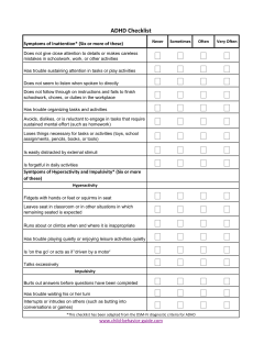
INTRODUCTION
−
IN−9
HOW TO TROUBLESHOOT ECU CONTROLLED
SYSTEMS
HOW TO PROCEED WITH TROUBLESHOOTING
IN01K−10
Carry out troubleshooting in accordance with the procedure on the following page. Here, only the basic procedure is shown. Details are provided in each section, showing the most effective methods for each circuit.
Confirm the troubleshooting procedures first for the relevant circuit before beginning troubleshooting of that
circuit.
Vehicle Brought Workshop
1
2
1
Ask the customer about the conditions and the
environment when the problem occurred.
Customer Problem
Analysis
Symptom Confirmation
and Diagnostic Trouble
Code Check
3
Symptom Simulation
2, 3
Confirm the symptoms and the problem conditions,
and check the diagnostic trouble codes.
(When the problem symptoms do not appear
during confirmation, use the symptom simulation
method described later on.)
4
Diagnostic Trouble
Code Chart
5
6
Matrix Chart of Problem
Symptoms
Circuit Inspection or Parts
Inspection
7
Repair
8
Confirmation Test
End
1HD−FTV ENGINE SUP (RM1179E)
4, 5, 6
Check the results obtain in Step 2, then confirm
the inspection procedure for the system or the part
which should be checked using the diagnostic
trouble code chart or the matrix chart of problem
symptoms.
7
Check and repair the affected system or part in
accordance with the instructions in Step 6.
8
After completing repairs, confirm that the problem
has been eliminated.
(If the problem is not reproduced, perform the
confirmation test under the same conditions and
in the same environment as when it occurred for
the first time.)
IN−10
INTRODUCTION
−
HOW TO TROUBLESHOOT ECU CONTROLLED
SYSTEMS
1.
CUSTOMER PROBLEM ANALYSIS
In troubleshooting, the problem symptoms must be confirmed accurately and all preconceptions must be
cleared away in order to give an accurate judgment. To ascertain just what the problem symptoms are, it is
extremely important to ask the customer about the problem and the conditions at the time it occurred.
Important Point in the Problem Analysis:
The following 5 items are important points in the problem analysis. Past problems which are thought to be
unrelated and the repair history, etc. may also help in some cases, so as much information as possible should
be gathered and its relationship with the problem symptoms should be correctly ascertained for reference
in troubleshooting. A customer problem analysis table is provided in the troubleshooting section for each
system for your use.
Important Points in the Customer Problem Analysis
D What −−−−− Vehicle model, system name
D When −−−−− Date, time, occurrence frequency
D Where −−−−− Road conditions
D Under what conditions? −−−−− Running conditions, driving conditions, weather conditions
D How did it happen? −−−−− Problem symptoms
(Sample) Engine control system check sheet.
CUSTOMER PROBLEM ANALYSIS CHECK
ENGINE CONTROL SYSTEM Check Sheet
Inspector’s
Name
Model and Model
Year
Driver’s Name
Frame No.
Data Vehicle
Brought in
Engine Model
License No.
Odometer Reading
Problem Symptoms
Customer’s Name
Engine does
not Start
Engine does not crank
Difficult to
Start
Engine cranks slowly
Other
Poor Idling
Incorrect first idle
Idling rpm is abnormal
Other
Rough idling
Poor
Drive ability
Hesitation
Knocking
Engine Stall
Soon after starting
After accelerator pedal depressed
During A/C operation
After accelerator pedal released
Shifting from N to D
Other
Back fire
Other
No initial combustion
High (
Muffler explosion (after−fire)
Others
Datas Problem
Constant
1HD−FTV ENGINE SUP (RM1179E)
Sometimes (
times per
day/month)
km
miles
No complete combustion
rpm)
Low (
Surging
rpm)
INTRODUCTION
−
IN−11
HOW TO TROUBLESHOOT ECU CONTROLLED
SYSTEMS
2.
SYMPTOM CONFIRMATION AND DIAGNOSTIC TROUBLE CODE CHECK
The diagnostic system in the LAND CRUISER fulfills various functions. The first function is the Diagnostic
Trouble Code Check in which a malfunction in the signal circuits to the ECU is stored in code in the ECU
memory at the time of occurrence, to be output by the technician during troubleshooting. Another function
is the Input Signal Check which checks if the signals from various switches are sent to the ECU correctly.
By using these check functions, the problem areas can be narrowed down quickly and troubleshooting can
be performed effectively. Diagnostic functions are incorporated in the following systems in the LAND CRUISER.
System
Engine
Diagnostic Trouble
Code Check
Input Signal Check
(Sensor Check)
Other Diagnosis
Function
f
(with Check Mode)
f
Diagnostic Test
Mode
In diagnostic trouble code check, it is very important to determine whether the problem indicated by the diagnostic trouble code is still occurring or occurred in the past but returned to normal at present. In addition,
it must be checked in the problem symptom check whether the malfunction indicated by the diagnostic
trouble code is directly related to the problem symptom or not. For this reason, the diagnostic trouble codes
should be checked before and after the symptom confirmation to determine the current conditions, as shown
in the table below. If this is not done, it may, depending on the case, result in unnecessary troubleshooting
for normally operating systems, thus making it more difficult to locate the problem, or in repairs not pertinent
to the problem. Therefore, always follow the procedure in correct order and perform the diagnostic trouble
code check.
DIAGNOSTIC TROUBLE CODE CHECK PROCEDURE
Diagnostic Trouble
Code Check (Make a
note of and then clear)
Diagnostic Trouble
Code Display
Confirmation
of Symptoms
Diagnostic Trouble
Code Check
Problem symptoms Same diagnostic
trouble code is
exist
displayed
Normal code is
displayed
Normal Code Display
Problem Condition
Problem is still occurring in the diagnostic
circuit
The problem is still occurring in a place
other than in the diagnostic circuit.
(The diagnostic trouble code displayed
first is either for a past problem or it is a
secondary problem.)
No problem
symptoms exist
The problem occurred in the diagnostic
circuit in the past.
Problem symptoms Normal code is
exist
displayed
The problem is still occurring in a place
other than in the diagnostic circuit.
No problem
symptoms exist
The problem occurred in a place other
than in the diagnostic circuit in the past.
1HD−FTV ENGINE SUP (RM1179E)
Normal code is
displayed
IN−12
INTRODUCTION
−
HOW TO TROUBLESHOOT ECU CONTROLLED
SYSTEMS
Taking into account the above points, a flow chart showing how to proceed with troubleshooting using the
diagnostic trouble code check is shown below. This flow chart shows how to utilize the diagnostic trouble
code check effectively, then by carefully checking the results, indicates how to proceed either to diagnostic
trouble code troubleshooting or to troubleshooting of problem symptoms.
Diagnostic trouble code check
Making a note of and clear ing of the diagnostic trouble codes displayed
Symptom confirmation
Problem symptoms
exist
No problem symptoms
exist
Simulation test using the symptom
simulation methods
Diagnostic trouble code check
D Diagnostic trouble code displayed
D Problem symptoms exist
D Normal code displayed
D Problem symptoms exist
Troubleshooting of problem indicated
by diagnostic trouble code
Troubleshooting of each
problem symptom
1HD−FTV ENGINE SUP (RM1179E)
D Normal code displayed
D No problem symptoms exist
System Normal
If a diagnostic trouble code was
displayed in the initial diagnostic
tr ouble c ode c hec k , it indic ates
that the trouble may have occurred
in a wire harness or connector in
that circuit in the past. Therefore,
check the wire harness and connectors (See page IN−19).
INTRODUCTION
−
HOW TO TROUBLESHOOT ECU CONTROLLED
SYSTEMS
IN−13
3.
SYMPTOM SIMULATION
The most difficult case in troubleshooting is when there are no problem symptoms occurring. In such cases,
a thorough customer problem analysis must be carried out, then simulate the same or similar conditions and
environment in which the problem occurred in the customer’s vehicle. No matter how much experience a
technician has, or how skilled he may be, if he proceeds to troubleshoot without confirming the problem
symptoms he will tend to overlook something important in the repair operation and make a wrong guess
somewhere, which will only lead to a standstill. For example, for a problem which only occurs when the engine is cold, or for a problem which occurs due to vibration caused by the road during driving, etc., the problem can never be determined so long as the symptoms are confirmed with the engine hot condition or the
vehicle at a standstill. Since vibration, heat or water penetration (moisture) are likely causes for problems
which are difficult to reproduce, the symptom simulation tests introduced here are effective measures in that
the external causes are applied to the vehicle in a stopped condition.
Important Points in the Symptom Simulation Test:
In the symptom simulation test, the problem symptoms should of course be confirmed, but the problem area
or parts must also be found out. To do this, narrow down the possible problem circuits according to the symptoms before starting this test and connect a tester beforehand. After that, carry out the symptom simulation
test, judging whether the circuit being tested is defective or normal and also confirming the problem symptoms at the same time. Refer to the matrix chart of problem symptoms for each system to narrow down the
possible causes of the symptom.
1
VIBRATION METHOD: When vibration seems to be the major cause.
CONNECTORS
Slightly shake the connector vertically and horizontally.
Shake Slightly
WIRE HARNESS
Slightly shake the wire harness vertically and horizontally.
The connector joint, fulcrum of the vibration, and body
through portion are the major areas to be checked thoroughly.
Swing Slightly
PARTS AND SENSOR
Vibrate Slightly
Apply slight vibration with a finger to the part of the sensor
considered to be the problem cause and check if the
malfunction occurs.
HINT: Applying strong vibration to relays may result in open
relays.
V07268
1HD−FTV ENGINE SUP (RM1179E)
IN−14
2
INTRODUCTION
−
HOW TO TROUBLESHOOT ECU CONTROLLED
SYSTEMS
HEAT METHOD: When the problem seems to occur when the suspect area is heated.
Heat the component that is the likely cause of the malfunction
with a hair dryer or similar object. Check to see if the malfunction
occurs.
NOTICE:
(1) Do not heat to more than 60 ˚C (140 ˚F). (Temperature
limit that no damage is done to the component.)
(2) Do not apply heat directly to parts in the ECU.
3
M a l f u n ction
WATER SPRINKLING METHOD: When the malfunction seems to occur on a rainy day or in a
high−humidity condition.
Sprinkle water onto the vehicle and check to see if the malfunction occurs.
NOTICE:
(1) Never sprinkle water directly into the engine
compartment, but indirectly change the temperature and
humidity by applying water spray onto the radiator front
surface.
(2) Never apply water directly onto the electronic
components.
(Service hint)
If a vehicle is subject to water leakage, the leaked water may
contaminate the ECU. When testing a vehicle with a water leakage problem, special caution must be used.
4
OTHER: When a malfunction seems to occur when electrical load is excessive.
Turn on all electrical loads including the heater blower, head
lights, rear window defogger, etc. and check to see if the malfunction occurs.
ON
V07469
1HD−FTV ENGINE SUP (RM1179E)
INTRODUCTION
−
IN−15
HOW TO TROUBLESHOOT ECU CONTROLLED
SYSTEMS
4.
DIAGNOSTIC TROUBLE CODE CHART
The inspection procedure is shown in the table below. This table permits efficient and accurate troubleshooting using the diagnostic trouble codes displayed in the diagnostic trouble code check. Proceed with troubleshooting in accordance with the inspection procedure given in the diagnostic chart corresponding to the
diagnostic trouble codes displayed. The engine diagnostic trouble code chart is shown below as an example.
D DTC No.
Indicates the diagnostic trouble code.
D Page or Instructions
Indicates the page where the inspection procedure
for each circuit is to be found, or gives instructions
for checking and repairs.
D Trouble Area
Indicates the suspect area of the
problem.
D Detection Item
Indicates the system of the problem or
contents of the problem.
DTC CHART (SAE Controlled)
HINT: Parameters listed in the chart may not be exactly the same as your reading due to the type of instrument
or other factors.
If a malfunction code is displayed during the DTC check in check mode, check the circuit for that code listed
in the table below. For details of each code, turn to the page referred to under the ”See page” for the respective
”DTC No.” in the DTC chart.
DTC No.
(See page)
P0100/31
(DI−25)
P0105/35
(DI−30)
P0110/24
(DI−35)
P0115/22
Trouble Area
Detection Item
Air Flow Meter Circuit
D Open or short in air flow meter circuit
D Air flow meter
D Engine ECU
Manifold Absolute Pressure/
Barometric Pressure Circuit
D Open or short in turbo pressure sensor circuit
D Turbo pressure sensor
D Open or short in VSV for turbo pressure sensor circuit
D Engine ECU
Intake Air Temperature Circuit
D Open or short in timing control valve circuit
D Intake air temp. sensor
D Engine ECU
Water Temperature Sensor Circuit
D Engine ECU
1HD−FTV ENGINE SUP (RM1179E)
*1
CHK
ENG
−
*2
Memory
IN−16
INTRODUCTION
−
HOW TO TROUBLESHOOT ECU CONTROLLED
SYSTEMS
5.
PROBLEM SYMPTOMS TABLE
The suspect circuits or parts for each problem symptom are shown in the table below. Use this table to troubleshooting the problem when a ”Normal” code is displayed in the diagnostic trouble code check but the
problem is still occurring. Numbers in the table indicate the inspection order in which the circuits or parts
should be checked.
HINT:
When the problem is not detected by the diagnostic system even though the problem symptom is present,
it is considered that the problem is occurring outside the detection range of the diagnostic system, or that
the problem is occurring in a system other than the diagnostic system.
D Page
Indicates the page where the flow chart for each circuit
is located.
D Circuit Inspection, Inspection Order
Indicates the circuit which needs to be checked for each problem
symptom. Check in the order indicated by the numbers.
D Problem Symptom
D Circuit or Part Name
Indicates the circuit or part which needs to be checked.
PROBLEM SYMPTOMS TABLE
Symptom
Engine not crank (Difficult to start)
No initial combustion (Difficult start)
Cold engine (Difficult to start)
Hot engine (Difficult to start)
1HD−FTV ENGINE SUP (RM1179E)
Suspect Area
1. Starter and starter relay
See page
−
1. Engine ECUpowersource circuit
2. Pre−heating system
3. Compression
4. Engine ECU
5. Injection Pump
DI−124
DI−127
EM−30
DI−128
FU−2
1. pre−heating system
2. STA signal circuit
3. Water temperature sensor
4. Injection nozzle
5. Fuel filter
6 Diesel throttle body
7. Engine ECU
8. Injection pump
DI−121
DI−127
DI−85
FU−15
FU−16
ED−5
D−I75
FU−2
1. STA signal circuit
2. Injection pump
3. Fuel filter
4. Diesel throttle body
5. Engine ECU
6. Injection pump
AC−54
DI−124
INTRODUCTION
−
HOW TO TROUBLESHOOT ECU CONTROLLED
SYSTEMS
IN−17
6.
CIRCUIT INSPECTION
How to read and use each page is shown below.
D Diagnostic Trouble Code No. and Detection Item
D Circuit Description
The major role and operation, etc. of the circuit
and its component parts are explained.
DTC
Timing Control System Malfunction
P1220/14
CIRCUIT DESCRIPTION
The engine ECU control the injection timing by actuating the timing control valve. The timing
control valve is mounted on the injection pump and delay one by duty control of pump internal
fuel pressure. The engine ECU detects the injection advance angle by TDC and NE signal.
DTC No.
Detection Item
Trouble Area
D Open or short in timing control valve circuit
P1220/14
After engine warm up and during, actual injection
D Fuel filter (Clogging)
timing is different from target vaue of engine ECU
D Fuel (Freezing Airin)
calculated for several sec.
D Injection pump (Internal pressure and timing
control valve)
D Engine ECU
D Indicates the diagnostic trouble code, diagnostic
trouble code set parameter and suspect area of
the problem.
WIRING DIAGRAM
ECU
Knock Sensor
GR
12
KNK
E6
E1
D Wiring Diagram
This shows a wiring diagram of the circuit.
Use this diagram together with ELECTRICAL
WIRING DIAGRAM to thoroughly understand the
circuit.
Wire colors are indicated by an alphabetical code.
B = Black, L = Blue, R = Red, BR = Brown,
LG = Light Green, V = Violet, G = Green,
O = Orange, W = White, GR = Gray, P = Pink,
Y = Yellow
The first letter indicates the basic wire color and
the second letter indicates the color of the stripe.
V08423
1HD−FTV ENGINE SUP (RM1179E)
IN−18
INTRODUCTION
−
HOW TO TROUBLESHOOT ECU CONTROLLED
SYSTEMS
D Indicates the position of the ignition switch during the check.
D Inspection Procedure
Use the inspection procedure to determine
if the circuit is normal or abnormal, and , if
it is abnormal, use it to determine whether
the problem is located in the sensors,
actuators, wire harness or ECU.
ON
LOCK
Ignition Switch ON
Ignition Switch LOCK (OFF)
START
ACC
Ignition Switch ACC
Ignition Switch START
INSPECTION PROCEDURE
1
Check continuity between terminal KNK of ECM connector and body ground.
PREPARATION:
(a) Remove the glove compartment (See page FI−37).
(b) Disconnect the E6 connector of ECM.
LOCK
KNK
CHECK:
Measure resistance between terminal KNK of ECU connector
and body ground.
E6 Connector
OK:
Resistance: 1 MW or higher
AB0117
A00265
A00255
OK
Go to step 3.
NG
2
Check knock sensor (See page FI−34).
OK
Replace knock sensor.
D Indicates the place to check the voltage or resistance.
D Indicates the connector position to checked, from the front or back side.
Wire Harness
Check from the connector back side.
(with harness)
Check from the connector front side. (without harness)
In this case, care must be taken not to bend the terminals.
D Indicates the condition of the connector of ECU during the check.
KNK
E6 Connector
Connector being checked is connected.
KNK
E6 Connector
Connector being checked is disconnected.
V08425
1HD−FTV ENGINE SUP (RM1179E)


© Copyright 2026