
ISSUE FOR BID SECTION 15010 BASIC MECHANICAL REQUIREMENTS PART 1 - GENERAL
ISSUE FOR BID
SECTION 15010
BASIC MECHANICAL REQUIREMENTS
PART 1 - GENERAL
1.1
RELATED DOCUMENTS
A.
Drawings and general provisions of Contract, including General and Supplementary
Conditions and Division -1 Specification Sections, apply to this Section.
B.
This is a Basic Mechanical Requirement Section and forms a part of the following Sections:
1.
1.2
All Division 15 Sections.
SUMMARY
A.
This Section includes general administrative and procedural requirements for mechanical
installations, including but not limited to:
1.
2.
3.
4.
5.
6.
7.
8.
9.
10.
11.
12.
13.
14.
15.
16.
17.
18.
19.
20.
21.
22.
23.
24.
25.
Proposed substitutions
Coordinate Work to Facilitate Testing, Adjusting, and Balancing
Codes, rules, regulations, ordinances and standards
Permits, inspections, tests and approvals.
References
Acceptable manufacturers
Contract drawings
Use of equipment
Layout drawings
Record documents
Maintenance and Operating Manuals
Submittals
Construction punch list
Delivery, storage and handling
Quality Assurance
Temporary protection and utilities
Warranty
Housekeeping
Rough-ins
Installation, coordination and special provisions
Cutting and patching
System activation
System and equipment adjustment
Maintenance of existing utility services
Demolition
BIG BLUE BUS TENANT IMPROVEMENT PROJECT
CITY OF SANTA MONICA
April 12, 2010
PROJECT NO.: 2008-00035-000
BASIC MECHANICAL REQUIREMENTS
15010 - 1
ISSUE FOR BID
26.
Testing, Start-Up and Training Procedures.
B.
Provide all labor, materials, tools, and equipment necessary to complete all work as specified
herein and noted on the Drawings.
C.
All work shall be installed in accordance with manufacturer's recommendations, industry
standards of good practice, and as specified herein and as noted on the Drawings.
1.3
PROPOSED SUBSTITUTIONS
A.
1.4
Refer to Division 1 "Substitutions".
COORDINATED WORK TO FACILITATE TESTING, ADJUSTING AND BALANCING
A.
1.5
Provide all labor, material and equipment necessary to complete all work to properly balance
all systems, including but not limited to, replacement of equipment drives, belts and sheaves at
no additional cost to accomplish the work specified in Section "Testing, Adjusting and
Balancing".
CODES, RULES, REGULATIONS, ORDINANCES AND STANDARDS
A.
In addition to the requirements shown or specified, comply with all applicable State, County,
City, Township and local Codes, Rules, Regulations, Ordinances and Standards.
B.
Comply with the requirements shown or specified when those requirements are in excess of
that required by Codes, Rules, Regulations, Standards and Ordinances.
C.
Advise the Architect of changes required to conform to State, County, and Local regulations,
ordinances and codes prior to the time that contract is awarded.
1.6
PERMITS, INSPECTIONS, TESTS, AND APPROVALS
A.
Secure and pay for all required permits, inspections, tests and approvals.
B.
Perform all tests required under applicable codes, rules, regulations, and ordinances.
C.
All parts of each system and associated equipment shall be tested and adjusted to work
properly and be left in good operating condition.
D.
Provide all testing instruments, gauges, pumps and other equipment required or necessary for
tests.
E.
Notify the Owner's Representative in advance of all tests and conduct all tests to his entire
satisfaction.
BIG BLUE BUS TENANT IMPROVEMENT PROJECT
CITY OF SANTA MONICA
April 12, 2010
PROJECT NO.: 2008-00035-000
BASIC MECHANICAL REQUIREMENTS
15010 - 2
ISSUE FOR BID
F.
Correct all defects disclosed in the work by tests or otherwise without additional cost to the
Owner.
G.
Repeat tests after any defects disclosed thereby have been corrected.
H.
Arrange and pay the cost of all utilities used in any tests.
I.
Blank off all equipment prior to tests which could be damaged by the test pressure.
J.
Listing of Referenced Associations, Codes, Standards and abbreviations:
AABC
AGA
AMCA
ANSI
ARI
ASHRAE
ASME
ASTM
AWS
AWWA
CPC
CMC
CISPI
FM
HI
IBR
IRI
MSS
NCPWB
NEC
NEMA
NEBB
NFPA
NSF
OSHA
PDI
HYDI
SMACNA
UBC
UPC
UMC
UL
K.
Associated Air Balance Council
American Gas Association
Air Moving and Conditioning Association
American National Standards Institute
Air-Conditioning and Refrigeration Institute
American Society of Heating, Refrigeration and Air-Conditioning
Engineers, Inc.
American Society of Mechanical Engineers
American Society for Testing & Materials
American Welding Society, Inc.
American Water Works Association, Inc.
California Plumbing Code.
California Mechaincal Code.
Cast Iron Soil Pipe Institute
Factory Mutual Engineering Corp.
Hydronics Institute
Standards by the Hydronics Institute
Industrial Risk Insurance
Manufacturer's Standardization Society of the Valve and Fitting
Industry
National Certified Pipe Welding Bureau
National Electrical Code
National Electrical Manufacturers Association
National Environmental Balancing Bureau
National Fire Protection Association
National Sanitation Foundation
Occupational Safety and Health Act
Plumbing and Drainage Institute
Standards by the Hydronics Institute
Sheet Metal and Air-Conditioning Contractors National Association, Inc.
Uniform Building Code, International Conference of Building Officials.
Uniform Plumbing Code
Uniform Mechanical Code
Underwriters' Laboratories, Inc.
Note: Latest edition applies unless otherwise noted on the drawings or herein.
BIG BLUE BUS TENANT IMPROVEMENT PROJECT
CITY OF SANTA MONICA
April 12, 2010
PROJECT NO.: 2008-00035-000
BASIC MECHANICAL REQUIREMENTS
15010 - 3
ISSUE FOR BID
1.7
ACCEPTABLE MANUFACTURERS
A.
1.8
Acceptable manufacturers shall be considered for material in accordance with the
requirements of the Specification Section, subject to the approval of the Architect. Such
approval concerns the manufacturer only and does not in any way act to permit any deviation
from strict compliance with the requirements of these Specifications.
CONTRACT DRAWINGS
A.
Contract Drawings for Mechanical Work are diagrammatic, intended to convey the scope of
the work and indicate general arrangement of equipment, ducts, piping and approximate sizes
and locations of equipment and outlets. Do not scale drawings for measurements.
B.
Consult Mechanical, Architectural, Structural and Electrical Contract Drawings and
Specifications to become familiar with all conditions affecting the Work, coordinate
interconnecting work with other Trades affected, and verify all spaces in which the work will
be installed.
C.
Where job conditions require reasonable changes in order to coordinate installation with other
trades, these changes shall be made without extra cost to the Owner.
D.
The Contract Drawings and Specifications are to be cooperative, and whatever is called for by
either shall be binding as if called for by both.
1.9
USE OF EQUIPMENT
A.
The use of any equipment, or any part thereof, for any purpose including testing even with the
Owner's consent, shall not be construed to:
1.
2.
3.
1.10
Be an acceptance of the work on the part of the Owner.
Obligate the Owner in any way to accept improper work or defective materials.
Be the basis for determining the beginning of the Contractor's guarantee or
manufacturer's warrantee period.
LAYOUT DRAWINGS
A.
Prepare layout drawings in accordance with Division 1 Section "Project Management and
Coordination", and as specified below.
B.
Prepare layout drawings drawn to scale showing the intended method of installation and
construction. Coordinate work with all other trades. Use the Contract Drawings and
Specifications as a guide in preparing coordination drawings. Comply with the full intent of
the Contract Drawings. Deviate from the Contract Drawings only as required to resolve
installation requirements. Layout drawings shall show the detailed routing of all piping and
ductwork and shall incorporate all requirements for; electrical conduit, buss duct, lighting and
BIG BLUE BUS TENANT IMPROVEMENT PROJECT
CITY OF SANTA MONICA
April 12, 2010
PROJECT NO.: 2008-00035-000
BASIC MECHANICAL REQUIREMENTS
15010 - 4
ISSUE FOR BID
cable tray systems; building structural systems; building architectural systems; and other items
as may be required.
C.
Layout drawings shall show all hangers, supports, guides, and anchors.
D.
Layout drawings shall show all equipment, valves, dampers, and specialties including the
required access spaces.
E.
The layout drawings shall not be a repetition of the Contract Drawings. Prepare coordination
drawings on a reproducible medium with dimensioned equipment and piping locations,
elevations and mounting details. Distinguish between piping in ceilings and piping exposed.
If available, electronic drawing files can be purchased from the Architect. Drawing size shall
match contract drawing size. Post changes and modifications as they occur.
F.
A set of layout drawings shall be kept on site and be available to the Architect, Owner's
Project Representative, and others.
G.
Layout drawings are not required to be submitted to the Architect.
H.
Update the layout drawings, when changes are made, so that these drawings represent the
currently constructed (or about to be constructed) conditions.
I.
Use the final layout drawings in preparing "Record Documents" as specified below and as
specified in "Project Closeout Procedures" section.
1.11
A.
RECORD DOCUMENTS
Prepare record documents in accordance with Division 1 Section "Project Closeout
Procedures". In addition to the requirements specified in Division 1, indicate the following
installed conditions:
1.
2.
3.
4.
5.
B.
Ductwork mains and branches, size and location, for both exterior and interior zones;
locations of dampers and other control devices; filters, boxes, and terminal units
requiring periodic maintenance or repair.
Mains and branches of piping systems, with valves and control devices located and
numbered, concealed unions located, and with items requiring maintenance located
(i.e., traps, strainers, expansion compensators, tanks, etc.). Valve location diagrams,
complete with valve tag chart.
Refer to Division 15 Section "Mechanical
Identification". Indicate actual inverts and horizontal locations of underground piping.
Equipment locations (exposed and concealed), dimensioned from prominent building
lines.
Approved substitutions, Contract Modifications, and actual equipment and materials
installed.
Contract Modifications, actual equipment and materials installed.
Engage the services of a Land Surveyor or Professional Engineer as specified in Division 1
Section "Field Engineering" to record the locations and invert elevations of underground
installations.
BIG BLUE BUS TENANT IMPROVEMENT PROJECT
CITY OF SANTA MONICA
April 12, 2010
PROJECT NO.: 2008-00035-000
BASIC MECHANICAL REQUIREMENTS
15010 - 5
ISSUE FOR BID
1.12
A.
MAINTENANCE AND OPERATING MANUALS
Prepare maintenance and operating manuals in accordance with Division 1 Section "Project
Closeout Procedures". In addition to the requirements specified in Division 1, include the
following information for equipment items:
1.
2.
3.
4.
5.
1.13
A.
Description of function, normal operating characteristics and limitations, performance
curves, engineering data and tests, and complete nomenclature and commercial
numbers of replacement parts.
Manufacturer's printed operating and maintenance data, parts list and procedures to
include start-up, break-in, and routine and normal operating instructions; regulation,
control, stopping, shutdown, and emergency instructions; and summer and winter
operating instructions.
Maintenance procedures and schedule for routine preventative maintenance and
troubleshooting; disassembly, repair, and reassembly; aligning and adjusting
instructions.
Servicing instructions and lubrication charts and schedules.
Drive belt replacement schedule.
SUBMITTALS
General:
1.
Submit each item in this Article according to the Conditions of the Contract and
Division 1 Specification Sections.
B.
Comply with the requirements of Section "Submittal Procedures" and as specified herein. All
required submittals for an item shall be submitted in a complete single package.
C.
Required submittals are listed in applicable Specification Sections. Submittals not required by
these Specifications will not be reviewed and will not be returned.
D.
After development and acceptance of the Contractor's construction schedule, prepare a
complete schedule of submittals in accordance with the requirements of Section "Submittal
Procedures".
E.
The following submittals are required prior to bid submission:
1.
2.
Proposed substitutions.
The following submittals are required prior to construction start:
a.
3.
Required product data.
The following submittals are required prior to construction punch list:
a.
b.
c.
All required shop drawings and product data.
Air test and balance reports.
Operating and maintenance manuals.
BIG BLUE BUS TENANT IMPROVEMENT PROJECT
CITY OF SANTA MONICA
April 12, 2010
PROJECT NO.: 2008-00035-000
BASIC MECHANICAL REQUIREMENTS
15010 - 6
ISSUE FOR BID
d.
e.
f.
F.
Shop Drawings:
1.
2.
3.
1.14
Record documents.
Guarantees and warranties.
Certifications, inspection and test reports.
Submit manufacturer's technical product data, including rated capacities of selected
model with clearly indicated, weights (shipping, installed, and operation), dimensions,
required clearances, and methods of assembly of components, furnished specialties and
accessories; and installation and start-up instructions.
Submit ladder-type wiring diagrams for power and control wiring. Clearly differentiate
between portions of wiring that are factory-installed and portions to be field-installed.
Submit maintenance data and parts list for all mechanical equipment; including "trouble
shooting" maintenance guide; plus servicing, and preventative maintenance procedures
and schedule. Include this data and product data in maintenance manual; in accordance
with requirements of Division 1.
CONSTRUCTION PUNCH LIST
A.
Inspect the work and operate all systems prior to requesting the construction punch list to
insure that the work is complete and operating in accordance with the requirements of the
Contract Documents.
B.
Prior to requesting construction punch list:
1.
2.
3.
4.
C.
1.15
Operate the HVAC system in the various modes of operation.
Verify the test and balance work is complete, reviewed and accepted by the Owner's
Representative.
Verify maintenance and operating manual work is complete, reviewed and accepted by
the Owner's Representative.
Verify system final adjustments and cleaning work is complete.
The final construction punch list time shall be coordinated with the Owner's Representative,
providing; minimum one (1) week notice.
DELIVERY, STORAGE, AND HANDLING
A.
Deliver products to the project properly identified with names, model numbers, types, grades,
compliance labels, and other information needed for identification.
B.
Receive, properly house, handle, hoist, deliver to proper location, equipment and other
material required.
C.
After delivery, before and after installation, protect equipment and materials against theft,
injury or damage from all causes.
BIG BLUE BUS TENANT IMPROVEMENT PROJECT
CITY OF SANTA MONICA
April 12, 2010
PROJECT NO.: 2008-00035-000
BASIC MECHANICAL REQUIREMENTS
15010 - 7
ISSUE FOR BID
D.
Provide factory-applied plastic end-caps on each length of pipe and tube, except for concrete,
corrugated metal, hub-and-spigot, clay piping. Maintain end-caps through shipping, storage
and handling to prevent pipe-end damage and prevent entrance of dirt, debris, and moisture.
E.
Protect stored pipes and tubes from moisture and dirt. Elevate above grade and enclose with
durable, waterproof wrapping. When stored inside, do not exceed structural capacity of the
floor.
F.
Protect flanges, fittings, and specialties from moisture and dirt by inside storage and
enclosure, or by packaging with durable, waterproof wrapping.
G.
Protect stored plastic pipes from direct sunlight. Support to prevent sagging and bending.
H.
Store equipment and materials in clean, dry space; store off the ground; protect from weather
and physical damage.
1.16
QUALITY ASSURANCE
A.
Applicable Codes and Standards.
B.
Installer's qualifications: Minimum 5 years of installation experience on successful projects
for the installing firm of the individual doing the installation, unless a higher minimum is
otherwise specifically noted in other Division 15 Specification Sections.
C.
Provide the following stamps and labels:
1.
2.
D.
Air Conditioning Equipment:
1.
1.17
"UL" or "ETL" label on all equipment with electrical connections.
ASME Code stamp/label on all boilers, water heaters, tanks and receivers.
Capacity ratings for air conditioning equipment shall be in accordance with applicable
ARI Standards with ASHRAE 90A minimum "COP" and "EER" efficiency levels.
TEMPORARY PROTECTION AND UTILITIES
A.
Provide temporary protection, construction water, heat and ventilation as specified in Division
1 Section "Temporary Facilities and Controls".
B.
Permanent HVAC equipment shall not be used for temporary heating, ventilating or air
conditioning unless written Owner approval is obtained. Refer to Division 1 Section
“Temporary Facilities and Controls”.
1.18
A.
WARRANTY
All systems, components, parts, assemblies and labor furnished under this contract shall be
warranted against defects in materials and workmanship in accordance with the General
BIG BLUE BUS TENANT IMPROVEMENT PROJECT
CITY OF SANTA MONICA
April 12, 2010
PROJECT NO.: 2008-00035-000
BASIC MECHANICAL REQUIREMENTS
15010 - 8
ISSUE FOR BID
Conditions. Any manufacturing or component defects arising during this warranty period
shall be corrected without cost to the Owner.
B.
1.19
A.
All applicable software as detailed in this specification shall be updated by the supplier free of
charge during and at the end of the warranty period. This will ensure that all system software
will be the most up-to-date software available.
HOUSEKEEPING
Maintain the premises neat and orderly and thoroughly clean upon completion of the work.
PART 2 - PRODUCTS
A.
All heating, ventilating, and air conditioning equipment; all service water heating equipment;
and all motors shall comply with the current state energy code, or the latest edition of the
ASHRAE/IESNA Standard 90.1 – if no state energy code exists.
PART 3 - EXECUTION
3.1
ROUGH-INS
A.
3.2
Verify final locations for rough-ins with field measurements and with the requirements of the
actual equipment to be connected.
INSTALLATION, COORDINATION AND SPECIAL PROVISIONS
A.
Sequence, coordinate, and integrate the various elements of mechanical systems, materials,
and equipment.
B.
Coordinate connection of electrical services to mechanical equipment.
C.
Sequence, coordinate, and integrate installations of mechanical materials and equipment for
efficient flow of the Work. Give particular attention to large equipment requiring positioning
prior to closing in the building.
D.
Coordinate mechanical systems, equipment, and materials installation with other building
components.
E.
Coordinate the installation of required supporting devices and sleeves to be set in poured-inplace concrete and other structural components, as they are constructed.
F.
Coordinate connection of mechanical systems with exterior underground and overhead
utilities and services. Provide required connection for each service.
BIG BLUE BUS TENANT IMPROVEMENT PROJECT
CITY OF SANTA MONICA
April 12, 2010
PROJECT NO.: 2008-00035-000
BASIC MECHANICAL REQUIREMENTS
15010 - 9
ISSUE FOR BID
G.
Coordinate installation of roof curbs and roof openings with roof structure and other
construction trades.
H.
Verify all dimensions by field measurements.
I.
Arrange for chases, slots, and openings in other building components during progress of
construction, to allow for mechanical installations.
J.
Coordinate installation of identifying devices after completing covering and painting where
identifying devices are applied to surfaces. Install identifying devices prior to installing
ceilings.
K.
Where mounting heights are not detailed or dimensioned, install systems, materials, and
equipment to provide the maximum headroom possible.
L.
Install systems, materials, and equipment to conform with approved submittal data, including
coordination drawings, to greatest extent possible. Conform to arrangements indicated by the
Contract Documents, recognizing that portions of the Work are shown only in diagrammatic
form.
M.
Install systems, materials, and equipment level and plumb, parallel and perpendicular to other
building systems and components.
N.
Roof mounted equipment shall be set "dead level" on curbs, grillage and supports constructed
to compensate for roof pitch.
O.
Install mechanical equipment to facilitate servicing, maintenance, and repair or replacement of
equipment components. As much as practical, connect equipment for ease of disconnecting,
with minimum of interference with other installations. Extend grease fittings to an accessible
location.
P.
Install systems, materials, and equipment giving right-of-way priority to systems required to
be installed at a specified slope.
3.3
CUTTING AND PATCHING
A.
Perform cutting and patching in accordance with Division 1 Section "Cutting and Patching".
B.
Perform cutting, fitting, and patching of mechanical equipment and materials required to:
1.
2.
3.
4.
5.
6.
Uncover Work to provide for installation of ill-timed Work.
Remove and replace defective Work.
Remove and replace Work not conforming to requirements of the Contract Documents.
Remove samples of installed Work as specified for testing.
Install equipment and materials in existing structures.
Upon written instructions from the Owner's Representative, uncover and restore Work
to provide for observation of concealed Work.
BIG BLUE BUS TENANT IMPROVEMENT PROJECT
CITY OF SANTA MONICA
April 12, 2010
PROJECT NO.: 2008-00035-000
BASIC MECHANICAL REQUIREMENTS
15010 - 10
ISSUE FOR BID
C.
Cut, remove and legally dispose of selected mechanical equipment, components and materials
as indicated, including, but not limited to, removal of mechanical piping, heating units,
plumbing fixtures and trim, and other mechanical items made obsolete by the new work.
D.
Protect the structure, furnishings, finishes, and adjacent materials not indicated or scheduled to
be removed.
E.
Provide and maintain temporary partitions or dust barriers adequate to prevent the spread of
dust and dirt to adjacent areas.
F.
Patch existing finished surfaces and building components using new materials matching
existing materials and experienced Installers. For installers' qualifications refer to the
materials and methods required for the surface and building components being patched.
G.
Refer to Division 1 Section "Definitions and Standards" for definition of "experienced
Installer".
H.
Patch finished surfaces and building components using new materials specified for the original
installation and experienced Installers. For installers' qualifications refer to the materials and
methods required for the surface and building components being patched.
I.
Refer to Division 1 Section "Reference Standards and Definitions" for definition of
"experienced Installer".
3.4
SYSTEM ACTIVATION
A.
Activation of the permanent heating, ventilating and air conditioning system for testing and
balancing will be allowed only after the building is substantially complete, or by written
request to and written permission of the Owner's Project Representative.
B.
Temporary filters shall be installed to prevent the accumulation of dust and dirt in all the duct
systems before the ventilating and air conditioning duct systems are activated. New filters
shall be provided and installed upon completion of the work and prior to acceptance of the
work by the Owner. If temporary filters get dirty during system activation, the filters must
then be replaced before starting system again.
C.
Prior to air testing and balancing thoroughly clean all ductwork. The entire system shall be rechecked for compliance with the drawings and specifications so that all components are free
from defects resulting from the early activation of the permanent ventilating and air
conditioning systems.
D.
Properly operate, and maintain the permanent heating, ventilating and air conditioning systems
to the time of final acceptance by the Owner. The minimum temperatures called for under
Temporary Heating shall be maintained during this period. Any adjustments and repairs
required to comply with the Specifications, tests, and balancing of the permanent heating
systems shall be made to the satisfaction of the Owner's Representative before final
acceptance. Make all repairs and adjustments required to put the heating and air conditioning
BIG BLUE BUS TENANT IMPROVEMENT PROJECT
CITY OF SANTA MONICA
April 12, 2010
PROJECT NO.: 2008-00035-000
BASIC MECHANICAL REQUIREMENTS
15010 - 11
ISSUE FOR BID
systems and equipment into first class condition before final acceptance by the Owner's
Representative.
3.5
SYSTEM AND EQUIPMENT ADJUSTMENT
A.
After the testing has been completed, energize all systems and equipment.
B.
Adjust all equipment and auxiliary devices for smooth and quiet operation.
C.
Check motor and coupling alignment to verify compliance with manufacturer's tolerances;
make adjustments as necessary.
D.
Lubricate all bearings.
E.
Adjust fan motor bases to the center adjustment position, wherever possible, to facilitate future
belt tightening.
F.
Check all motors and bearings for overheating and make necessary adjustments - if required.
G.
Submit a "System and Equipment Adjustment" report to the Architect. This report shall
address all of the items listed above.
3.6
MAINTENANCE OF EXISTING UTILITY SERVICES
A.
Uninterrupted normal use of the existing facilities must be maintained during the time required
to perform the complete installation of the work indicated in the Contract Documents. It is
mandatory that the existing buildings be maintained in service.
B.
Investigate existing conditions and the location of all existing equipment and the location of
all existing services before starting.
C.
If a service is disturbed, immediately without regard for working hours, place the service back
into operation.
D.
Sufficient advance notice shall be given to the Owner and its permission obtained prior to
interruption of present services. It should be assumed that disruption of utilities and services
will be done at other than normal working hours. No additional or extra payment will be
authorized to comply with these requirements.
E.
Repair, replace and maintain in service any utilities, facilities, or services (underground,
overground, interior or exterior) damaged, broken or otherwise rendered inoperative during
the course of construction in the existing building.
F.
All openings must be securely covered, or otherwise protected, to prevent injury due to
carelessly or maliciously dropped tools or materials, grit, dirt, or any foreign matter.
Damaged work shall be repaired or replaced until work is fully and finally accepted.
BIG BLUE BUS TENANT IMPROVEMENT PROJECT
CITY OF SANTA MONICA
April 12, 2010
PROJECT NO.: 2008-00035-000
BASIC MECHANICAL REQUIREMENTS
15010 - 12
ISSUE FOR BID
G.
3.7
Protect motors, pumps, electrical equipment, heating equipment and all similar items of
equipment from dirt, grime, plaster, paint and water during all phases of construction. This
protection shall be provided by covering with transparent plastic sheeting.
DEMOLITION
A.
General:
1.
2.
3.
4.
5.
6.
7.
8.
9.
B.
Existing Active Piping
1.
C.
When encountered protect, brace, and support existing active piping where required for
proper execution of the work. If existing active piping is encountered that is not
indicated or noted in the Contract Documents and that requires relocation, make request
in writing to the Owner's Representative for a determination. Do not proceed with the
work until written directions are received from the Owner's Representative. Do not
prevent or disturb the operation of the active piping that is to remain.
Existing Inactive Piping and Ductwork:
1.
D.
Demolish, remove, demount, and disconnect abandoned mechanical materials and
equipment indicated to be removed and not indicated to be salvaged or saved.
Protect adjacent materials indicated to remain. Install and maintain dust and noise
barriers to keep dirt, dust, and noise from being transmitted to adjacent areas. Remove
protection and barriers after demolition operations are complete.
Locate, identify, and protect mechanical services passing through demolition area and
serving other areas outside the demolition limits. Maintain services to areas outside
demolition limits. When services must be interrupted, install temporary services for
affected areas.
Materials and Equipment to be Salvaged: Remove, demount, and disconnect existing
mechanical materials and equipment indicated to be removed and salvaged, and deliver
materials and equipment to the location designated for storage.
Disposal and Cleanup: Remove from the site and legally dispose of demolished
materials and equipment not indicated to be salvaged.
Clean area after demolition of work to satisfaction of Owner's Designated
Representative.
Repair or replace equipment or materials damaged during demolition to satisfaction of
Owner's designated representative.
Remove, reconnect, cap, plug and replace existing piping and ductwork only where
indicated in the Contract Documents.
Remove and/or replace existing equipment, valves, controls, etc., only where indicated
in the Contract Documents.
When encountered in the Work, remove protect, cap or plug existing inactive piping or
ductwork. If existing inactive piping and ductwork is encountered that is not indicated
or noted in the Contract Documents and that interfere with the Work, make request in
writing to the Owner's Representative for a determination.
Interruption of Existing Active Piping:
BIG BLUE BUS TENANT IMPROVEMENT PROJECT
CITY OF SANTA MONICA
April 12, 2010
PROJECT NO.: 2008-00035-000
BASIC MECHANICAL REQUIREMENTS
15010 - 13
ISSUE FOR BID
1.
E.
Interruption of Existing Utility Service:
1.
2.
F.
Coordinate the shut-off and disconnection of utility services with the Owner and the
utility company.
Notify the Owner's Representative Owner's Project Representative at least 5 days prior
to commencing demolition operations.
Scheduling:
1.
2.
3.8
Where the Work makes temporary shut-down of services unavoidable, shut down at
such time as approved by the Owner, which will cause least interference with
established operating routine. Arrange to work continuously, including overtime, if
required to make necessary connection to existing work.
Submit schedules indicating proposed methods and sequence of operations for
demolition prior to commencement of Work. Include coordination for shut-off of
utility services and details for dust and noise control.
Coordinate sequencing with construction phasing and Owner occupancy specified in
Division 1 Section "Summary of the Work".
TESTING, START-UP, AND TRAINING PROCEDURES
A.
Develop and implement a plan and schedule for the testing, start-up, and training for all new
mechanical equipment. This plan will be specific to the project.
B.
Provide any testing equipment and re-testing necessary.
C.
In addition to all required submittal data for approval of the equipment, O & M Manuals, and
warrantee information, provide documentation on all testing, start-up, and training activities.
This documentation will include but is not limited to:
1.
2.
3.
4.
5.
6.
7.
8.
Installation, Start-up, and Check-out materials shipped with the equipment
Factory or Field Check-out forms used by factory or field technicians
Pre-functional and Functional Test Procedures and Check Lists
Start-up and System Operational Procedures and Check Lists
Sequences of Operation, Control Drawings, or other equipment documentation
Training Manuals
Re-testing of all deficiencies or non-conformance issues
Video tape of all training sessions.
D.
Develop project-specific forms and check-lists for the equipment on this project.
E.
All testing, start-up, and training will be scheduled in the Contractor’s Master Schedule.
Seasonal testing and deferred testing will also be part of this contract. Seasonal tests will be
delayed until weather conditions are closest to the system’s design. Deferred tests due to the
building structure, required occupancy phasing, or other deficiencies will be completed as
soon as possible. Seasonal and deferred testing will follow the same procedures, be witnessed
by the same personnel, and require the same documentation.
BIG BLUE BUS TENANT IMPROVEMENT PROJECT
CITY OF SANTA MONICA
April 12, 2010
PROJECT NO.: 2008-00035-000
BASIC MECHANICAL REQUIREMENTS
15010 - 14
ISSUE FOR BID
F.
Functional performance testing and verification may be achieved by manual testing or
monitoring the performance and analyzing the results using the control system’s trend log
capabilities. Simulating conditions may be allowed, though timing the testing to experience
actual conditions is encouraged wherever practical. Each function and test shall be performed
under conditions that simulate actual conditions as close as is practically possible. The
contractor executing the test shall provide all necessary materials, system modifications, etc.
to produce the necessary flows, pressures, temperatures, etc. necessary to execute the test
according to the specified conditions. At completion of the test the contractor shall return al
affected building equipment and systems to their pre-test condition.
G.
All pre-functional and pre-start-up activities will be documented by the mechanical contractor
and submitted before arrangements are made for the functional tests and start-up. At least 7
working days shall be provided.
H.
Submit at project close-out with the as-built drawings, a document certifying that:
1.
2.
3.
4.
5.
6.
I.
Systems were tested and function per design intent
Systems were installed per manufacturers recommendations and to industry accepted
minimum standards
Systems received adequate operational check-out by installing contractors
Proper performance of equipment and systems was documented and given to the
Owner.
O & M Manuals and as-built drawings are complete and accurate.
Owner’s operating personnel are adequately trained.
Owner training shall include a minimum of 16 hours of instruction for all equipment and
systems. Where individual Division 15 Sections specify hours of Owner training, they shall
be in addition to the base 16 hours of training.
END OF SECTION 15010
BIG BLUE BUS TENANT IMPROVEMENT PROJECT
CITY OF SANTA MONICA
April 12, 2010
PROJECT NO.: 2008-00035-000
BASIC MECHANICAL REQUIREMENTS
15010 - 15
ISSUE FOR BID
SECTION 15050
BASIC MECHANICAL MATERIALS AND METHODS
PART 1 - GENERAL
1.1
RELATED DOCUMENTS
A.
Drawings and general provisions of Contract, including General and Supplementary
Conditions and Division -1 Specification Sections, apply to this Section.
B.
This is a Basic Mechanical Materials and Methods Section and forms a part of the following
Sections:
1.
C.
Related Sections: The following Sections contain requirements that relate to this Section:
1.
1.2
All Division 15 Sections.
See Architectural Drawings.
SUMMARY
A.
Extent of Basic Mechanical Materials and Methods is indicated on Drawings and by the
requirements of this Section.
B.
Types of items specified in this Section include:
1.
2.
3.
4.
5.
1.3
Joint Sealers
Access Doors and Frames
Pipe Joining Materials
Piping Specialties
Sleeves
SUBMITTALS
A.
General: Submit the following according to the Conditions of the Contract and Division 1
Specification Sections.
B.
Product data for following piping specialties:
C.
Shop Drawings:
D.
None required.
BIG BLUE BUS TENANT IMPROVEMENT PROJECT
PROJECT NO.: 2008-00035-000
CITY OF SANTA MONICA
BASIC MECHANICAL MATERIAL AND METHODS
April 12, 2010
15050 - 1
ISSUE FOR BID
E.
Welder certificates signed by Contractor certifying that welders comply with requirements
specified under the "Quality Assurance" Article.
PART 2 - PRODUCTS
2.1
JOINT SEALERS
A.
2.2
Refer to Architectural drawings for "Joint Sealants" and "Firestopping" for specifics regarding
joint sealants, joint fillers, material colors, and other related materials.
ACCESS DOORS AND FRAMES
A.
Comply with requirements of Architectural drawings for "Access Doors and Frames".
1.
2.
2.3
Equipment access door size shall be not less than 24" x 24".
Access doors for Plumbing valves in wall shall be not less than 8”x8”.
PIPE JOINING MATERIALS
A.
Brazing Materials:
1.
B.
Soldering Materials:
1.
2.4
Comply with SFAA-5.8, Section II, ASME Boiler and Pressure Vessel Code for
brazing filler metal materials appropriate for the materials being joined.
Refer to individual piping system specifications for solder appropriate for each
respective system.
PIPING SPECIALTIES
A.
Escutcheons:
1.
2.
Chrome-plated, stamped steel, hinged, split-ring escutcheon, with set screw. Inside
diameter shall closely fit pipe outside diameter, or outside of pipe insulation where pipe
is insulated. Outside diameter shall completely cover the opening in floors, walls, or
ceilings.
Acceptable Manufacturers: Subject to compliance with requirements, provide products
of one of the following:
a.
b.
c.
B.
Chicago Specialty Mfg. Co.
Sanitary-Dash Mfg. Co.
Grinnell Co.
Unions:
BIG BLUE BUS TENANT IMPROVEMENT PROJECT
PROJECT NO.: 2008-00035-000
CITY OF SANTA MONICA
BASIC MECHANICAL MATERIAL AND METHODS
April 12, 2010
15050 - 2
ISSUE FOR BID
1.
2.
3.
Malleable-iron, Class 150 for low pressure service and class 250 for high pressure
service; hexagonal stock, with ball-and-socket joints, metal-to-metal bronze seating
surfaces; female threaded ends.
Acceptable Manufacturers: Subject to compliance with requirements, provide products
of one of the following:
Grinnell Co.
a.
b.
c.
C.
Dielectric Unions:
1.
2.
Provide dielectric unions with appropriate end connections for the pipe materials in
which installed (screwed, soldered, or flanged), which effectively isolate dissimilar
metals, prevent galvanic action, and stop corrosion.
Acceptable Manufacturers: Subject to compliance with requirements, provide products
of one of the following:
a.
b.
c.
D.
Epco Sales, Inc.
Eclipse, Inc.
Perfection Corp.
Epco Sales Inc.
Eclipse Inc.
Perfection Corp.
Y-Type Strainers:
1.
General:
a.
b.
2.
3.
4.
5.
Provide strainers full line size of connecting piping, with ends matching piping
system materials. Screens shall be Type 304 stainless steel, with 3/64"
perforations at 233 per square inch.
Provide strainers with 125 psi working pressure rating for low pressure
applications, and 250 psi pressure rating for high pressure application.
Threaded Ends, 2" and Smaller: Cast-iron body, screwed screen retainer with centered
blowdown fitted with pipe plug.
Threaded Ends, 2-1/2" and Larger: Cast-iron body, bolted screen retainer with offcenter blowdown fitted with pipe plug.
Grooved Ends, 2-1/2" and Larger: Tee pattern, ductile-iron or malleable-iron body and
access end cap, access coupling with EDPM gasket.
Acceptable Manufacturers: Subject to compliance with requirements, provide products
of one of the following:
a.
b.
c.
d.
e.
f.
Grinnell Gruvlok Co.
Watts Reg. Co.
Hayward Industrial Products Inc.
Trane Co.
Armstrong Machine Works.
Hoffman Specialty ITT.
BIG BLUE BUS TENANT IMPROVEMENT PROJECT
PROJECT NO.: 2008-00035-000
CITY OF SANTA MONICA
BASIC MECHANICAL MATERIAL AND METHODS
April 12, 2010
15050 - 3
ISSUE FOR BID
g.
2.5
Victaulic Co. of America (low pressure applications only).
SLEEVES
A.
Sheet-Metal Sleeves:
longitudinal joint.
10 gage, galvanized sheet metal, round tube closed with welded
B.
Steel Sleeves: Schedule 40 galvanized, welded steel pipe, ASTM A 53, Grade A.
C.
Fire Barrier Sleeves, Sealers, Etc.:
"Firestopping".
Comply with applicable code requirements for
PART 3 - EXECUTION
3.1
INSTALLATION
A.
General:
1.
2.
3.
4.
5.
6.
7.
3.2
Install all materials and equipment in accordance with the manufacturer's
recommendations.
Conceal all pipe installations in walls, pipe chases, utility spaces, above ceilings, below
grade or floors, unless indicated otherwise.
Install piping free of sags or bends and with ample space between piping to permit
proper insulation applications.
Install exposed piping at right angles or parallel to building walls. Diagonal runs are
not permitted, unless expressly indicated on the Drawings.
Install piping tight to slabs, beams, joists, columns, walls, and other permanent
elements of the building. Provide space to permit insulation applications, with 1"
clearance outside the insulation. Allow sufficient space above removable ceiling panels
to allow for panel removal.
Locate groups of pipes parallel to each other, spaced to permit applying full insulation
and servicing of valves.
Install drains at low points in mains, risers, and branch lines consisting of a tee fitting,
3/4 ball valve, and short 3/4 threaded nipple and cap.
SLEEVES
A.
Provide and set sleeves to accommodate piping passing through foundations, walls, floors and
partitions.
1.
Exterior Wall and Floor Penetrations: Seal pipe penetrations through exterior walls and
floors. Provide steel sleeves with integral circumferential water stop collar and
mechanical sleeve seals for exterior wall penetrations. Terminate wall sleeves flush
with walls. Terminate floor sleeves flush with the bottom of floor slabs and extend
sleeve 1-1/2 inches above the top of floor slabs.
BIG BLUE BUS TENANT IMPROVEMENT PROJECT
PROJECT NO.: 2008-00035-000
CITY OF SANTA MONICA
BASIC MECHANICAL MATERIAL AND METHODS
April 12, 2010
15050 - 4
ISSUE FOR BID
2.
Interior Wall Penetrations: Provide steel pipe sleeves for all piping 6 inch diameter and
smaller and sheet metal sleeves for piping larger than 6 inch diameter. Terminate
sleeves flush with walls.
a.
b.
3.
Interior Fire Rated Wall and Floor Penetrations: Provide steel pipe sleeves. Terminate
floor sleeves flush with the bottom of the floor slab and extend sleeve 1-1/2 inches
above the top of floor slabs.
a.
b.
c.
3.3
Uninsulated Piping: Pack annular space between pipe and sleeve with U.L. rated
ceramic fiber insulation.
Insulated Piping: Extend insulation through pipe sleeve. Seal between insulation
and sleeve with silicone sealant.
Uninsulated Piping: Provide firestop material and sealant in accordance with
Division 7 Section "Firestopping".
Insulated Piping: Extend insulation through sleeve and provide firestop material
and sealant in accordance with Division 7 Section "Firestopping".
Plastic Piping: Provide firestop material, sealant and firestop sleeve in
accordance with Division 7 Section "Firestopping".
FITTINGS AND SPECIALTIES
A.
Use fittings for all changes in direction and all branch connections.
B.
Remake leaking joints using new materials.
C.
Install strainers where indicated on the drawings.
D.
Install unions adjacent to each valve, and at the final connection to each piece of equipment
and plumbing fixture having 2" and smaller connections, and where indicated on the
drawings.
E.
Install dielectric unions to connect piping materials of dissimilar metals.
3.4
JOINTS
A.
Steel Pipe Joints:
1.
B.
Pipe 2" and Smaller: Thread pipe with tapered pipe threads in accordance with ANSI
2.1. Cut threads full and clean using sharp dies. Ream threaded ends to remove burrs
and restore full inside diameter. Apply pipe joint lubricant or sealant suitable for the
service for which the pipe is intended on the male threads at each joint and tighten joint
to leave not more than 3 threads exposed.
Non-Ferrous Pipe Joints:
1.
Brazed and Soldered Joints:
BIG BLUE BUS TENANT IMPROVEMENT PROJECT
PROJECT NO.: 2008-00035-000
CITY OF SANTA MONICA
BASIC MECHANICAL MATERIAL AND METHODS
April 12, 2010
15050 - 5
ISSUE FOR BID
a.
b.
C.
3.5
For copper tube and fitting joints, braze joints in accordance with ANSI B31.1.0 Standard Code for Pressure Piping, Power Piping and ANSI B9.1 -Standard
Safety Code for Mechanical Refrigeration.
Thoroughly clean tube surface and inside surface of the cup of the fittings, using
very fine emery cloth, prior to making soldered or brazed joints. Wipe tube and
fittings clean and apply flux. Flux shall not be used as the sole means for
cleaning tube and fitting surfaces.
Other Pipe Joints: Joints for other piping materials are specified within the respective piping
system sections.
APPLICATION OF JOINT SEALERS
A.
3.6
Comply with requirements of code for "Joint Sealants" and "Firestopping".
ACCESS TO EQUIPMENT AND MISCELLANEOUS SPECIALTIES
A.
All control devices, specialties, dampers, valves, etc., shall be installed so as to provide for
easy access for adjustment, maintenance, and repair. Manual dampers, located within or
above inaccessible ceilings may be installed with extended operators which terminate flush
with the exposed ceiling/wall surface in lieu of access doors.
B.
Provide ceiling/wall access doors/panels and frames for access to mechanical equipment,
valves, dampers, controls, and all other items which require regular cleaning and/or
adjustment. Equipment requiring servicing located above an inaccessible ceiling shall be
within 3’-0” (maximum) of closest edge of access panel provided.
C.
Coordinate installation of ceiling/wall access doors/panels with other trades.
END OF SECTION 15050
BIG BLUE BUS TENANT IMPROVEMENT PROJECT
PROJECT NO.: 2008-00035-000
CITY OF SANTA MONICA
BASIC MECHANICAL MATERIAL AND METHODS
April 12, 2010
15050 - 6
ISSUE FOR BID
SECTION 15060
BASIC MECHANICAL MATERIALS AND METHODS HANGERS AND SUPPORTS
PART 1 - GENERAL
1.1
RELATED DOCUMENTS
A.
Drawings and general provision of the Contract, including General and Supplementary
Conditions and Division -1 Specification Sections, apply to this Section.
B.
This is a Basic Mechanical Materials and Methods Section and forms a part of the following
Sections:
1.
C.
Related Sections: The following Sections contain requirements that relate to this Section:
1.
1.2
All Division 15 Sections referencing “Basic Mechanical Materials and Methods –
Hangers and Supports”.
See Architectural Drawings.
SUMMARY
A.
Extent of Basic Mechanical Materials and Methods - Hangers and Supports is indicated on
Drawings and by the requirements of this Section, or other Sections referencing “Basic
Mechanical Materials and Methods – Hangers and Supports”.
B.
Types of items specified in this Section include the following:
1.
2.
3.
4.
5.
6.
7.
8.
9.
C.
Supplemental Framing.
Horizontal Pipe Hangers and Supports.
Vertical Pipe Hangers and Supports.
Hanger Attachments.
Building Attachments.
Saddles and Shields.
Spring Hangers and Supports.
Miscellaneous Materials.
Strut Channel Supports and Components.
Provide all supports, supplemental framing, anchors, guides, platforms, and bases for all new
equipment, piping, and ductwork as specified in this Section; and as indicated on the
drawings; and/or specified in other Division-15 Sections.
BIG BLUE BUS TENANT IMPROVEMENT PROJECT
PROJECT NO.: 2008-00035-000
CITY OF SANTA MONICA
BASIC MECHANICAL MATERIALS AND METHODS
HANGERS AND SUPPORTS
April 12, 2010
15060 - 1
ISSUE FOR BID
D.
Supports that are an integral part of factory-fabricated equipment, are specified as part of
equipment assembly in other Division-15 Sections.
E.
Support components or systems shown on the Drawings are minimum requirements and are to
be used as a guide only.
1.3
SUMMARY
A.
Provide all supports, supplemental framing, anchors, guides, platforms, and bases for all new
equipment, piping, and ductwork as specified in this Section; and as indicated on the
drawings; and/or specified in other Division-15 Sections.
B.
Supports that are an integral part of factory-fabricated equipment, are specified as part of
equipment assembly in other Division-15 Sections.
C.
Support components or systems shown on the Drawings are minimum requirements and are to
be used as a guide only.
D.
Fire protection piping shall be supported independently.
E.
Related Sections: The following Sections contain requirements that relate to this Section:
1.
2.
1.4
Division-15 Section "Basic Mechanical Materials and Methods" applies to this Section.
Division-15 Section "Mechanical Vibration Control", for spring type hangers and
seismic restraint requirements.
SUBMITTALS
A.
General:
1.
B.
Product Data:
1.
C.
None required.
Shop Drawings:
1.
D.
Submit each item in this Article according to the Conditions of the Contract and
Division 1 Specification Sections.
None required.
Maintenance Data:
1.
As part of the project closeout requirements, submit maintenance data and parts list for
each type of support and anchor. Include this data, product data, and shop drawings in
maintenance manual; in accordance with requirements of Division 1.
BIG BLUE BUS TENANT IMPROVEMENT PROJECT
PROJECT NO.: 2008-00035-000
CITY OF SANTA MONICA
BASIC MECHANICAL MATERIALS AND METHODS
HANGERS AND SUPPORTS
April 12, 2010
15060 - 2
ISSUE FOR BID
1.5
QUALITY ASSURANCE
A.
Manufacturer's Qualifications:
1.
B.
Firms regularly engaged in manufacture of supports and anchors, of types and sizes
required, whose products have been in satisfactory use in similar service for not less
than 5 years.
Codes and Standards:
1.
2.
3.
Code Compliance: Comply with all applicable codes, including ANSI, pertaining to
product materials and installation of supports and anchors.
UL and FM Compliance: Provide products, where applicable, which are UL-listed and
FM approved.
MSS Standard Compliance:
a.
b.
c.
d.
Provide pipe hangers and supports of which materials, design, and manufacture
comply with MSS SP-58.
Select and install pipe hangers and supports, complying with MSS SP-69.
Fabricate and install pipe hangers and supports, complying with MSS SP-89.
Terminology used in this Section is defined in MSS SP-90.
PART 2 - PRODUCTS
2.1
GENERAL
A.
All supports and parts shall conform to the latest requirements of ANSI Code for Power
Piping B31.1. and MSS Standard Practice SP-58, except as supplemented or modified by the
requirements of this Specification.
B.
Hangers shall be designed so that they cannot become disengaged by movement of the
supported pipe.
C.
Rigid riser supports shall be designed so that the load is always equalized, and at no time can
one side of the support be completely unloaded by the riser moving out of plumb, thereby
transferring the entire load to the opposite side. Wherever practical, support riser piping
independently of the connected horizontal piping.
D.
Hangers, supports, hanger rod attachments and building attachments shall be provided by the
same manufacturer where possible.
E.
Provide plastic-coated hangers for glass, aluminum, brass, and copper piping systems.
F.
All hanger and support materials to be located outdoors shall be galvanized.
G.
Ductwork shall be supported by threaded rod hangers or metal straps. Use of wire hangers is
not allowed.
BIG BLUE BUS TENANT IMPROVEMENT PROJECT
PROJECT NO.: 2008-00035-000
CITY OF SANTA MONICA
BASIC MECHANICAL MATERIALS AND METHODS
HANGERS AND SUPPORTS
April 12, 2010
15060 - 3
ISSUE FOR BID
2.2
SUPPLEMENTAL FRAMING
A.
Provide supplemental framing for the following conditions:
1.
2.
3.
B.
2.3
Where the anchor locations do not align with the structural framing.
Where the intended loads exceed the structural framing maximum load carrying
capacity.
Floor mounted supplemental supports may only be used where indicated or with
specific approval of the Owner's Representative.
Provide supplemental framing or reinforcing straps, within the joist, to transfer the load to a
panel point wherever proposed hanger locations do not align with a steel joist panel point.
Refer to structural drawings for typical joist reinforcing details.
HORIZONTAL-PIPING HANGERS AND SUPPORTS
A.
General:
1.
Select size of hangers and supports to exactly fit pipe size for bare piping, and to
exactly fit around piping insulation with saddle or shield for insulated piping.
B.
Adjustable Steel Clevis Hangers: MSS Type 1.
C.
Steel Double Bolt Pipe Clamps: MSS Type 3.
D.
U-Bolts: MSS Type 24, with plastic coating for glass, aluminum,
brass and copper piping systems.
E.
Pipe Stanchion Saddles: MSS Type 37, including steel pipe base
support and cast-iron floor flange.
BIG BLUE BUS TENANT IMPROVEMENT PROJECT
PROJECT NO.: 2008-00035-000
CITY OF SANTA MONICA
BASIC MECHANICAL MATERIALS AND METHODS
HANGERS AND SUPPORTS
April 12, 2010
15060 - 4
ISSUE FOR BID
F.
Single Pipe Rolls: MSS Type 41.
G.
Pipe Roll Stands: MSS Type 44.
H.
Adjustable Roller Hanger: MSS Type 43
I.
Adjustable Roller Hanger: MSS Type 46
2.4
VERTICAL-PIPING CLAMPS
A.
General:
1.
Select size of vertical piping clamps to exactly fit pipe size of bare pipe.
B.
Two-Bolt Riser Clamps: MSS Type 8.
C.
Four-Bolt Riser Clamps: MSS Type 42.
2.5
HANGER-ROD ATTACHMENTS
A.
General:
BIG BLUE BUS TENANT IMPROVEMENT PROJECT
PROJECT NO.: 2008-00035-000
CITY OF SANTA MONICA
BASIC MECHANICAL MATERIALS AND METHODS
HANGERS AND SUPPORTS
April 12, 2010
15060 - 5
ISSUE FOR BID
1.
2.
Hanger rods and attachments to the structure shall be subjected to tensile loading only
and shall be designed with a minimum safety factor of five (5). Hanger rod diameters
shall be compatible with the other component parts of the hanger assembly.
Select size of hanger-rod attachments to suit hanger rods.
B.
Steel Turnbuckles: MSS Type 13.
C.
Steel Clevises: MSS Type 14.
D.
Swivel Turnbuckles: MSS Type 15.
E.
Malleable Iron Sockets: MSS Type 16.
BIG BLUE BUS TENANT IMPROVEMENT PROJECT
PROJECT NO.: 2008-00035-000
CITY OF SANTA MONICA
BASIC MECHANICAL MATERIALS AND METHODS
HANGERS AND SUPPORTS
April 12, 2010
15060 - 6
ISSUE FOR BID
F.
2.6
Steel Weldless Eye Nuts: MSS Type 17.
BUILDING ATTACHMENTS
A.
General:
1.
2.
3.
4.
Select attachments to suit building substrate conditions.
Select size of building attachments to suit hanger rods, load restrictions and building
material.
Provide supplemental framing wherever hanger locations are not directly below
building attachment locations.
Do not attach supports to metal floor decking (or roof decking) panels.
B.
Concrete Inserts: MSS Type 18.
C.
Expansion Bolts (into Concrete Constructed Buildings):
1.
2.
3.
Bolts shall be rated to support dynamic loads.
Selection Criteria; Follow manufacturer's written guidelines. Include consideration of
actual concrete strength and reduction in capacity due to location (in regard to tension
zones), edge distance and spacing of fasteners.
Manufacturers: Subject to compliance with requirements, ACI Committee Report ACI
355, IR-91 and above, provide expansion bolts of one of the following:
a.
b.
c.
Liebig Ultraplus by Liebig International, Charlotteville, VA.
Fischer Zykon by Structural Anchoring System, Worcester, MA.
Hilti HSL by Hilti, Tulsa, OK.
D.
Center Beam Clamps: MSS Type 21.
E.
Linked Steel Clamps w/ Eye Nut: MSS Type 29.
BIG BLUE BUS TENANT IMPROVEMENT PROJECT
PROJECT NO.: 2008-00035-000
CITY OF SANTA MONICA
BASIC MECHANICAL MATERIALS AND METHODS
HANGERS AND SUPPORTS
April 12, 2010
15060 - 7
ISSUE FOR BID
F.
Steel Beam Clamp wit Eye Nut: MSS Type 28.
G.
Malleable Beam Clamp with Extension Piece: MSS Type 30.
H.
Side Beam Clamp, with Counterbalance: MSS Type 27.
I.
Side Beam or Channel Clamp, with Counterbalance: MSS Type 20.
J.
Top Beam Clamp, with Counterbalance: MSS Type 25.
K.
Steel Brackets: One of the following for indicated loading:
1.
Loading up to 750 lbs.: MSS Type 31.
BIG BLUE BUS TENANT IMPROVEMENT PROJECT
PROJECT NO.: 2008-00035-000
CITY OF SANTA MONICA
BASIC MECHANICAL MATERIALS AND METHODS
HANGERS AND SUPPORTS
April 12, 2010
15060 - 8
ISSUE FOR BID
2.7
2.
Loading up to 1500 lbs.: MSS Type 32.
3.
Loading up to 3000 lbs.: MSS Type 33.
SADDLES AND SHIELDS
A.
General:
1.
2.
B.
Protection Saddles: MSS Type 39.
1.
2.
C.
Except as otherwise indicated, provide factory-fabricated saddles or shields under
piping hangers and supports for all insulated piping.
Size saddles and shields for exact fit to mate with pipe insulation.
Fill interior voids with segments of insulation matching
adjoining insulation.
Saddle shall be of same material as pipe.
Protection Shields: MSS Type 40.
1.
Length and gage as recommended by manufacturer to
prevent crushing of insulation.
2.
Manufacturer: Subject to compliance with requirements, provide thermal hanger
shields of one of the following:
a.
Pipe Shields, Inc.
BIG BLUE BUS TENANT IMPROVEMENT PROJECT
PROJECT NO.: 2008-00035-000
CITY OF SANTA MONICA
BASIC MECHANICAL MATERIALS AND METHODS
HANGERS AND SUPPORTS
April 12, 2010
15060 - 9
ISSUE FOR BID
2.8
SPRING HANGERS AND SUPPORTS
Control")
A.
(Refer to Division 15 "Mechanical Vibration
General:
1.
Select spring hangers and supports to suit
pipe size, loading and load restrictions.
B.
Spring Cushion Hangers: MSS Type 48.
C.
Spring Cushion Roll Hangers: MSS Type 49.
D.
Spring Sway Braces: MSS Type 50.
E.
Variable Spring Hangers: MSS Type 51.
1.
F.
Preset to indicated load and limit variability
factor to 25%.
Variable Spring Base Supports: MSS Type 52.
1.
Preset to indicated load and limit variability factor to 25%;
include load flange.
BIG BLUE BUS TENANT IMPROVEMENT PROJECT
PROJECT NO.: 2008-00035-000
CITY OF SANTA MONICA
BASIC MECHANICAL MATERIALS AND METHODS
HANGERS AND SUPPORTS
April 12, 2010
15060 - 10
ISSUE FOR BID
G.
Variable Spring Trapeze Hangers: MSS Type 53.
1.
H.
Preset to indicated load and limit variability factor to
25%.
Constant Supports:
1.
2.
Provide one of the following types, selected to suit piping
system.
a.
Horizontal Type: MSS Type 54.
b.
Vertical Type: MSS Type 55.
c.
Trapeze Type: MSS Type 56.
Include auxiliary stops for erection and hydrostatic test, and field load-adjustment
capability.
BIG BLUE BUS TENANT IMPROVEMENT PROJECT
PROJECT NO.: 2008-00035-000
CITY OF SANTA MONICA
BASIC MECHANICAL MATERIALS AND METHODS
HANGERS AND SUPPORTS
April 12, 2010
15060 - 11
ISSUE FOR BID
2.9
MANUFACTURERS OF HANGERS AND SUPPORTS
A.
The following are acceptable manufacturers subject to compliance with specified
requirements.
1.
2.
3.
2.10
A.
MISCELLANEOUS MATERIALS
Metal Framing:
1.
B.
Provide products complying with ASTM A 36.
Cement Grout:
1.
D.
Provide products complying with NEMA STD ML 1.
Steel Plates, Shapes and Bars:
1.
C.
Michigan Hanger Co.
Carpenter and Patterson, Inc.
Anvil International.
Provide portland cement (ASTM C 150, Type I or Type III) and clean; uniformly
graded, natural sand (ASTM C 404 size No. 2). Mix at a ration of 1.0 part cement to
3.0 parts sand, by volume, with minimum amount of water required for placement and
hydration.
Heavy-Duty Steel Trapezes:
1.
Fabricate from steel shapes selected for loads required; weld steel in accordance with
AWS standards.
E.
Pipe Guides:
F.
Provide factory-fabricated guides, of carbon steel, consisting of bolted two-Section outer
cylinder and base with two-Section guiding spider bolted tight to pipe.
G.
Size guide and spiders to clear pipe and insulation (if any), and cylinder.
H.
Provide guides of length recommended by manufacturer to allow indicated travel.
2.11
STRUT CHANNEL SUPPORTS AND COMPONENTS
A.
General: Strut shall be 1-5/8 inch wide in varying heights and welded combinations as
required to meet load capacities and designs indicated on the Drawings.
B.
Material and Finish: Material and finish specifications for each type are as follows:
BIG BLUE BUS TENANT IMPROVEMENT PROJECT
PROJECT NO.: 2008-00035-000
CITY OF SANTA MONICA
BASIC MECHANICAL MATERIALS AND METHODS
HANGERS AND SUPPORTS
April 12, 2010
15060 - 12
ISSUE FOR BID
1.
2.
C.
Epoxy Painted: Strut shall be made from steel meeting the minimum mechanical
properties of ASTM A1011 33,000 PSI min. yield, then painted with water born epoxy
applied by a cathodic electro-deposition process. Fittings shall be manufactured from
steel meeting the minimum requirements of ASTM A1018 33,000 PSI min. yield. The
fittings shall have the same epoxy finish as the strut. Threaded hardware shall be zinc
plated in accordance with ASTM B633 Service Class 1. Service Class 1 in not an
acceptable coating for fittings or components other than threaded hardware.
Pre-Galvanized Steel: Strut shall be made from steel meeting the minimum mechanical
properties of ASTM A653 33,000 PSI min. yield, mill galvanized coating designation
G90. Fittings shall be manufactured form steel meeting the minimum requirements of
ASTM A1018 33,000 PSI min. yield and zinc plated in accordance with ASTM B633
Service Class 3. Threaded hardware shall be zinc plated in accordance with ASTM
B633 Service Class 1. Service Class 1 in not an acceptable coating for fittings or
components other than threaded hardware.
Manufacturers: Subject to compliance with requirements, provide products by one of the
following:
1.
2.
3.
4.
5.
Allied Support Systems, Power-Strut.
Cooper B-Line.
GS Metals Corp, Globe Strut.
Thomas & Betts Corporation, Superstrut.
Unistrut.
PART 3 - EXECUTION
3.1
GENERAL
A.
Locate hangers to avoid interference with all building components including lights, ducts,
conduits, pipes and equipment.
B.
Coordinate the location of all support devices cast into concrete with structural steel
drawings.
C.
Prohibited:
1.
2.
Attachment of support devices to the roof deck.
Attachment of support devices to reinforcing angles around roof opening.
D.
Coordinate the location of all equipment and material being supported with other trades
supporting equipment and material in the same space or area.
E.
Examine areas and conditions under which supports and anchors are to be installed. Do not
proceed with work until unsatisfactory conditions have been corrected.
BIG BLUE BUS TENANT IMPROVEMENT PROJECT
PROJECT NO.: 2008-00035-000
CITY OF SANTA MONICA
BASIC MECHANICAL MATERIALS AND METHODS
HANGERS AND SUPPORTS
April 12, 2010
15060 - 13
ISSUE FOR BID
3.2
SPACING AND LOADING GUIDELINES
A.
The structural documents list the maximum suspended load capacities of the framing.
Suspended load capacity indicated for a floor is the available total capacity to hang from the
underside of that floor.
B.
Layout support locations within guidelines of MSS SP 69 and the pipe hanger spacing table
contained herein; increase number of supports as required in order to meet structural load
limitations.
C.
Tabulate the load on each support, taking into consideration the weights of all components
(including those provided by other trades) which are upheld by a common support.
D.
Verify that the supported loads do not exceed the load limits of the structural framing.
3.3
PREPARATION
A.
Proceed with installation of supplemental framing, hangers, supports and anchors only after
required building structural work has been completed. Correct inadequacies including (but not
limited to) proper placement of inserts, anchors and other building structural attachments.
B.
Coordinate sequence, installation and associated work with all the various Contractors and
subcontractors and inspection agencies for the purpose of reviewing material selections and
procedures to be followed in performing the work.
3.4
INSTALLATION OF BUILDING ATTACHMENTS
A.
General:
1.
2.
3.
4.
5.
6.
Install building attachments at required locations within concrete, structural steel or
supplemental framing for proper piping support.
Space attachments within maximum piping span length as specified herein, horizontal
steel and iron piping table or horizontal copper tubing included in this Section or
spacing required to structural load limitations indicated on the documents.
Install additional hangers and building attachments as required to comply with
structural load limitations and at concentrated loads, including valves, flanges, guides,
strainers, expansion joints, and at changes in direction of piping.
Install concrete inserts before concrete is placed; fasten insert securely to forms.
Install reinforcing bars through openings at top of inserts.
Beam Clamps:
a.
b.
Beam clamps shall be center loading Type 21, 28, 29 and 30, unless otherwise
specified or indicated.
When it is not possible to use center loading beam clamps and subject to prior
approval by the Architect/Engineer before their use, eccentric loading, "J" type
beam clamps, Types 20, 25 and 27 may be used within the following limitations:
BIG BLUE BUS TENANT IMPROVEMENT PROJECT
PROJECT NO.: 2008-00035-000
CITY OF SANTA MONICA
BASIC MECHANICAL MATERIALS AND METHODS
HANGERS AND SUPPORTS
April 12, 2010
15060 - 14
ISSUE FOR BID
1)
2)
3)
4)
7.
"C" Clamps:
a.
b.
8.
The use of "C" clamps and beam clamps of "C" pattern and any modification
thereof is prohibited for attachment to joists.
"C" clamps may be used to attach pipes to 2" and smaller to steel beams.
Concrete Inserts:
a.
b.
3.5
For loads equivalent to water piping sizes 2 inches and less.
For loads equivalent to water piping sizes 2 inches through 10 inches
provided two counterbalancing clamps are used per point of pipe support
and pipe is mounted on trapeze.
Where more than one rod is used per point of support, rod diameter shall
be determined in accordance with referenced standards.
Note: "J" type beam clamps shall not be used for attachments to joists.
Concrete inserts shall be Type 18 when applied to loads equivalent to piping in
sizes 2 inches IPS and larger, and where otherwise required by imposed loads, a
one foot length of 1/2-inch reinforcing rod shall be inserted and wired through
wing slots.
Proprietary type continuous inserts may be proposed subject to approval of the
Architect.
INSTALLATION OF HANGERS, SUPPORTS AND SUPPLEMENTAL FRAMING
A.
General:
1.
2.
3.
4.
5.
B.
Install hangers, supports, supplemental framing, clamps and attachments to support
piping properly from building structure; comply with MSS SP-69.
Arrange for grouping of parallel runs of horizontal piping to be supported together on
trapeze type hangers where possible.
Trapeze hangers, space hangers for smallest pipe size or install intermediate supports
for smaller diameter pipe.
Do not use wire or perforated metal to support piping, and do not support piping from
other piping.
Where horizontal piping movements are such that the hanger rod angularity from the
vertical is greater than 4 degrees from the cold to hot position of the pipe, the hanger
pipe and structural attachments shall be offset in such manner that the rod is vertical in
the hot position.
Support fire-water piping directly from the structure independent of other piping, duct, and
electrical systems.
1.
Exception: Runouts to individual sprinkler heads may be supported from other piping
or duct system supports in accordance with NFPA-13 requirements.
BIG BLUE BUS TENANT IMPROVEMENT PROJECT
PROJECT NO.: 2008-00035-000
CITY OF SANTA MONICA
BASIC MECHANICAL MATERIALS AND METHODS
HANGERS AND SUPPORTS
April 12, 2010
15060 - 15
ISSUE FOR BID
C.
Provisions for Movement: Install hangers and supports to allow controlled movement of
piping systems and to permit freedom of movement between pipe anchors, and to facilitate
action of expansion joints, expansion loops, expansion bends and similar units.
D.
Load Distribution: Install hangers and supports so that piping live and dead loading and
stresses from movement will not be transmitted to connected equipment.
E.
Pipe Slopes: Install hangers and supports to provide indicated pipe slopes, and so that
maximum pipe deflections allowed by ANSI B31 Pressure Piping Codes are not exceeded.
F.
Horizontal Pipe Attachments (Single Pipes):
1.
2.
3.
4.
G.
Uninsulated pipe shall be supported by Type 1 or Type 3 attachments, except as
otherwise specified or indicated.
All insulated piping, which is intended to operate at or below ambient air temperature,
shall be supported by a combination of Type 1 attachment and shields. Provide rigid
insulation at all pipe shields.
All insulated piping 2-1/2" size and larger, which is intended to operate above ambient
air temperature, shall be supported by a combination of Types 41, 44, or 49, roller
hangers and Type 39 saddles.
All insulated piping shall be supported with oversized hangers to accommodate the
insulation thickness as herein specified.
Pipe Hanger Spacing:
1.
2.
3.
4.
Pipe hangers for horizontal piping shall be spaced as follows, unless otherwise directed
and shall be provided with the minimum rod sizes shown, complete with all necessary
adjusting and lock nuts.
Spacing and minimum rod diameter indicated in the following tables shall be used
unless more frequent hanging or larger rod diameters are required to conform with MSS
Standard SP-69, safety factor requirements indicated in this specification, or load
restrictions indicated on the structural requirements.
Horizontal Steel and Iron Piping:
Pipe Size
Minimum Rod Diameter
Maximum Hanger Spacing
3/4" and smaller
1" to 1-1/4"
1-1/2"
2"
2-1/2"
3"
3-1/2"
4”
5”
6”
3/8"
3/8"
3/8"
3/8"
1/2"
1/2"
1/2"
5/8"
5/8"
3/4"
5'
7'
9'
10'
11'
12’
12’
12’
12’
12’
Horizontal Copper Tubing:
BIG BLUE BUS TENANT IMPROVEMENT PROJECT
PROJECT NO.: 2008-00035-000
CITY OF SANTA MONICA
BASIC MECHANICAL MATERIALS AND METHODS
HANGERS AND SUPPORTS
April 12, 2010
15060 - 16
ISSUE FOR BID
5.
6.
Nom. Tubing Size
Minimum Rod Diameter
Maximum Hanger Spacing
1/2" and smaller
3/4" to 1-1/4"
1-1/2" to 2"
2-1/2" to 3"
4" to 5"
6"
3/8"
3/8"
1/2"
1/2"
5/8"
3/4"
5'
6'
6'
9’
10’
10’
Hangers and supports shall also be provided at every change of direction and within 1'
of any pipe fitting and valve.
Hanger spacing for iron hub and spigot piping shall not exceed 5 feet. Each length of
cast iron pipe shall have at least two (2) hangers and each fitting one (1) hanger.
Hangers shall be entirely separated from hangers for any other pipe and so located that
there will be no strains on any joint.
Nom. Tubing Size
Minimum Rod Diameter
Maximum Hanger Spacing
¾” and smaller
1” to 2”
2 ½” to 3 ½”
4” and 5”
6”
3/8"
3/8"
1/2"
5/8"
3/4"
2.4’
4’
4’
4’
4’
Note 1: Continuous support required for all piping containing liquids above 75
deg.F.
H.
Risers: Riser pipe shall be supported independently of the connected horizontal piping and as
indicated below.
1.
2.
3.
4.
I.
Saddles and Shields (For Insulated Piping):
1.
2.
J.
Cast iron piping shall be supported at every floor and at is base.
Steel piping shall be supported at every other floor, and at is base.
Copper pipe shall be supported at every floor.
All plastic piping shall be supported at a maximum spacing of 4’-0”.
Shields: Where low-compressive-strength insulation or vapor barriers are indicated,
install coated protective shields.
Saddles: Where insulation without vapor barrier is indicated, install protection saddles.
Hang and support metal ductwork systems in accordance with the latest edition of "SMACNA
HVAC DUCT CONSTRUCTION STANDARDS METAL AND FLEXIBLE" with the
following exceptions:
1.
Wire hangers are not acceptable.
BIG BLUE BUS TENANT IMPROVEMENT PROJECT
PROJECT NO.: 2008-00035-000
CITY OF SANTA MONICA
BASIC MECHANICAL MATERIALS AND METHODS
HANGERS AND SUPPORTS
April 12, 2010
15060 - 17
ISSUE FOR BID
2.
3.
3.6
Acceptable expansion bolts are limited to those specified herein.
The use of "C" clamps shall be limited to attach duct sizes equivalent to 12 inch round
and smaller to steel beams.
INSTALLATION OF SPRING HANGERS AND SUPPORTS
A.
Refer also to Division 15 Section "Mechanical Vibration Control".
B.
The total travel for constant support hangers shall be equal to actual travel plus 20%. In no
case shall the difference between actual and total travel be less than 1/2 inch.
C.
Constant supports shall be furnished with travel stops. The travel stops shall be factory
installed so that the hanger lever is at the "cold" position. The travel stops shall be of such
design as to permit future re-engagement even in the event the lever is at a position other than
"cold" without having to make hanger rod adjustments.
3.7
INSTALLATION OF ANCHORS
A.
Install anchors at proper locations to prevent stresses from exceeding those permitted by ANSI
B31, and to prevent transfer of loading and stresses to connected equipment.
B.
Fabricate and install anchor by welding steel shapes, plates and bars to piping and to structure.
Comply with ANSI B31 and with AWS standards.
C.
Where expansion compensators are indicated, install anchors in accordance, with expansion
unit manufacturer's written instructions, to limit movement of piping and forces to maximums
recommended by manufacturer for each unit.
3.8
INSTALLATION OF SWAY BRACES
A.
3.9
Provide sway braces at locations requiring lateral support to eliminate pipe movement. Sway
braces shall be MSS Type 50.
EQUIPMENT SUPPORTS
A.
Provide structural steel stands to support equipment not floor mounted or hung from structure.
Construct of structural steel members or steel pipe and fittings. Provide factory-fabricated
tank saddles for tanks mounted on steel stands. Structural steel equipment supports which are
to be located outside shall be hot dipped galvanized after fabrication. Paint all non-galvanized
support members with primer formulated for application on bare metal.
BIG BLUE BUS TENANT IMPROVEMENT PROJECT
PROJECT NO.: 2008-00035-000
CITY OF SANTA MONICA
BASIC MECHANICAL MATERIALS AND METHODS
HANGERS AND SUPPORTS
April 12, 2010
15060 - 18
ISSUE FOR BID
3.10
A.
STRUT CHANNEL SUPPORTS AND COMPONENTS
Use the following strut channel support system, unless otherwise noted or indicated on the
Drawings.
1.
Indoors:
a.
3.11
General Areas: Epoxy painted.
ADJUSTING AND CLEANING
A.
Hanger Adjustments: Adjust hangers so as to distribute loads equally on attachments.
B.
Support Adjustment: Provide grout under supports so as to bring piping and equipment to
proper level and elevations.
END OF SECTION 15060
BIG BLUE BUS TENANT IMPROVEMENT PROJECT
PROJECT NO.: 2008-00035-000
CITY OF SANTA MONICA
BASIC MECHANICAL MATERIALS AND METHODS
HANGERS AND SUPPORTS
April 12, 2010
15060 - 19
ISSUE FOR BID
SECTION 15070
BASIC MECHANICAL MATERIALS AND METHODS MECHANICAL VIBRATION CONTROLS
PART 1 - GENERAL
1.1
RELATED DOCUMENTS
A.
Drawings and general provisions of the Contract, including General and Supplementary
Conditions and Division -1 Specification Sections, apply to this Section.
B.
This is a Basic Mechanical Materials and Methods Section and forms a part of the following
Sections:
1.
1.2
Division 15 Sections referencing “Basic Mechanical Materials and Methods –
Mechanical Vibration Controls”.
SUMMARY
A.
Extent of vibration control work required by this section is indicated on drawings and by the
requirements of this Section or other Sections referencing “Basic Mechanical Materials and
Methods – Mechanical Vibration Controls”.
B.
Types of vibration control products specified in this section include the following:
1.
2.
3.
C.
1.3
Roof-Curb Isolators
Isolation Hangers
Flexible Pipe Connectors
Mechanical vibration controls that are an integral part of factory fabricated equipment, are
specified as part of equipment assembly in other Division 15 Sections.
SUBMITTALS
A.
General:
1.
B.
Submit each item in this Article according to the Conditions of the Contract and
Division 1 Specification Sections.
Product Data:
BIG BLUE BUS TENANT IMPROVEMENT PROJECT
PROJECT NO.: 2008-00035-000
CITY OF SANTA MONICA
BASIC MECHANICAL MATERIALS AND METHODS
MECHANICAL VIBRATION CONTROLS
April 12, 2010
15070 - 1
ISSUE FOR BID
1.
Submit manufacturer's technical product data and installation instructions for each type
of vibration control product. Include a schedule showing:
a.
b.
c.
d.
e.
f.
C.
Include drawings with the following information:
1.
D.
2.
Submit manufacturer's assembly-type shop drawings indicating dimensions, weights,
required clearances, and method of assembly of components. Detail bases, and show
location of equipment anchoring points, coordinated with equipment manufacturer's
shop drawings.
Submit calculations, certified by a professional engineer, for the design and selection of
the seismic restraints.
Maintenance Data:
1.
1.4
Equipment layout locating isolators and seismic restraints.
Shop Drawings:
1.
E.
Isolator Type and Model Number.
Isolator size.
Isolator unloaded height.
Isolator loaded static deflection.
Isolator location relative to equipment served.
Total weight and load distribution for isolated equipment.
Submit maintenance data for each type of vibration control product. Include this data,
product data, and shop drawings in maintenance manual; in accordance with
requirements of Division 1.
QUALITY ASSURANCE
A.
Manufacturer's Qualifications: Firms regularly engaged in manufacture of vibration control
products, of type, size, and capacity required, whose products have been in satisfactory use in
similar service for not less than 5 years.
B.
Professional Engineer Qualifications: A professional engineer who is legally qualified to
practice in the jurisdiction where the Project is located and who is experienced in providing
engineering services of the kind indicated. Engineering services are defined as those
performed for installations of vibration isolation bases and seismic restraints that are similar to
those indicated for this project in material, design and extent.
C.
Except as otherwise indicated, obtain vibration control products from single manufacturer.
BIG BLUE BUS TENANT IMPROVEMENT PROJECT
PROJECT NO.: 2008-00035-000
CITY OF SANTA MONICA
BASIC MECHANICAL MATERIALS AND METHODS
MECHANICAL VIBRATION CONTROLS
April 12, 2010
15070 - 2
ISSUE FOR BID
1.5
COORDINATION
A.
Coordinate layout and installation of vibration isolation and seismic-restraint devices with
other construction that penetrates ceilings or is supported by them, including light fixtures,
HVAC equipment, fire-suppression-system components, and partition assemblies.
B.
Coordinate installation of roof curbs, equipment supports, and roof penetrations.
PART 2 - PRODUCTS
2.1
ACCEPTABLE MANUFACTURERS
A.
Manufacturer: Subject to compliance with requirements, provide vibration control products of
one of the following:
1.
2.
3.
4.
5.
6.
2.2
Amber/Booth Co.
Korfund Dynamics Corp.
Mason Industries, Inc.
Peabody Noise Control, Inc.
Vibration Eliminator Co., Inc.
Vibration Mountings and Controls, Inc.
GENERAL
A.
Unless otherwise noted, all mechanical equipment shall be mounted on vibration isolation to
prevent the transmission of vibration and mechanically transmitted sound to the building
structure. Vibration isolators shall be selected in accordance with weight distribution so as to
produce reasonably uniform deflection. SPECIFICATION TYPES for Bases and Isolators
shall be as hereinafter described. Bases, Isolators and Static Deflections shall be as noted on
the VIBRATION ISOLATION SCHEDULE.
B.
Vibration eliminators shall be properly sized for the actual loading and application. Failure of
the vibration eliminators to perform as a result of improper sizing shall be the responsibility of
this Contractor. The mountings shall be replaced at no additional cost to the Owner.
C.
All flexible pipe connectors used in potable water systems shall be suitable for potable water
service and shall have no deleterious effect on water quality.
2.3
SPECIFICATION TYPES
A.
Specification A:
1.
Vibration hangers shall contain a steel spring and 0.3" deflection neoprene element in
series. The neoprene element shall be molded with a rod isolation bushing that passes
through the hanger box. Springs shall have a minimum additional travel to solid equal
BIG BLUE BUS TENANT IMPROVEMENT PROJECT
PROJECT NO.: 2008-00035-000
CITY OF SANTA MONICA
BASIC MECHANICAL MATERIALS AND METHODS
MECHANICAL VIBRATION CONTROLS
April 12, 2010
15070 - 3
ISSUE FOR BID
to 50% of the rated deflection. Hangers shall be Type DNHS as manufactured by
Mason Industries, Inc.
B.
Specification B:
1.
C.
Specification C:
1.
D.
Not used.
Specification G:
1.
H.
Not used.
Specification F:
1.
G.
Vibration hangers shall contain a steel spring and 0.3" deflection neoprene element in
series. The neoprene element shall be molded with a rod isolation bushing that passes
through the hanger box. Spring diameters and hanger box lower hole sizes shall be
large enough to permit the hanger rod to swing thru a 30E arc before contacting the hole
and short circuiting the spring. Springs shall have a minimum additional travel to solid
equal to 50% of the rated deflection. Submittals shall include a scale drawing of the
hanger showing the 30E capacity. Hangers shall be Type 30N as manufactured by
Mason Industries, Inc.
Specification E:
1.
F.
Not used.
Specification D:
1.
E.
Spring type isolators shall be free standing and laterally stable without any housing and
complete with 1/4" neoprene acoustical friction pads between the baseplate and the
support. All mountings shall have leveling bolts that must be rigidly bolted to the
equipment. Spring diameters shall be no less than 0.8 of the compressed height of the
spring at rated load. Springs shall have a minimum additional travel to solid equal to
50% of the rated deflection. Submittals shall include spring diameters, deflections,
compressed spring height and solid spring height. Mountings shall be Type SLF as
manufactured by Mason Industries, Inc.
Vibration isolator manufacturer shall furnish integral structural steel bases. All
perimeter members shall be beams with a minimum depth equal to 1/10th of the longest
dimension of the base. Beam depth need not exceed 14" provided that the deflection
and misalignment is kept within acceptable limits as determined by the manufacturer.
Height saving brackets shall be employed in all mounting locations to provide a base
clearance of one inch. Bases shall be Type WF as manufactured by Mason Industries,
Inc. Bases for H & V & A.C. units shall be Type MSL by Mason Industries, Inc.
Specification H:
BIG BLUE BUS TENANT IMPROVEMENT PROJECT
PROJECT NO.: 2008-00035-000
CITY OF SANTA MONICA
BASIC MECHANICAL MATERIALS AND METHODS
MECHANICAL VIBRATION CONTROLS
April 12, 2010
15070 - 4
ISSUE FOR BID
1.
I.
Specification J:
1.
J.
Not used.
Specification K:
1.
K.
Not used.
Not used.
Specification L:
1.
Not used.
L.
Specification M:
M.
1. Not used.
N.
Specification N:
1.
O.
Specification P:
1.
P.
Not used.
Specification Y:
1.
R.
Not used.
Specification X:
1.
Q.
Not used.
Not used.
Specification Z:
1.
Curb mounted rooftop equipment shall be mounted on vibration isolation bases that fit
over the roof curb and under the isolated equipment. The extruded aluminum top
member shall overlap the bottom member to provide water runoff independent of the
seal. The aluminum members shall house cadmium plated springs having a 1"
minimum deflection with 50% additional travel to solid. Spring diameters shall be no
less than 0.8 of the spring height at rated load. Wind resistance shall be provided by
means of resilient snubber sin the corners with a minimum clearance of 1/2" so as not to
interfere with the spring action except in high winds. The weather seal shall consist of
continuous closed cell sponge materials both above and below the base and a
waterproof flexible duct-like EPDM connection joining the outside perimeter of the
aluminum members. Foam or other contact seals are unacceptable at the spring cavity
closure. Caulking shall be kept to a minimum. Submittals shall include spring
BIG BLUE BUS TENANT IMPROVEMENT PROJECT
PROJECT NO.: 2008-00035-000
CITY OF SANTA MONICA
BASIC MECHANICAL MATERIALS AND METHODS
MECHANICAL VIBRATION CONTROLS
April 12, 2010
15070 - 5
ISSUE FOR BID
deflections, spring diameters, compressed spring height and solid spring height as well
as seal and wind resistance details. Curb mounted bases shall be Type CMAB, as
manufactured by Mason Industries, Inc.
2.4
VIBRATION ISOLATION SCHEDULE
GRADE OR BASEMENT
EQUIPMENT
FLOORS ABOVE GRADE
MINIMUM
MINIMUM
SPECIFICATION STATIC
SPECIFICATION STATIC
TYPE
DEFLECTION TYPE
DEFLECTION
(in.)
(in.)
FACTORY ASSEMBLED AC UNITS (NOTE 1)
Curb Mounted ROOFTOP
UNITS
--
--
Z
2.0
Suspended Units
Thru 5 HP
A
1.0
a
1.0
Floor Mounted Units
Thru 5 HP
B, G
.75
B-G
.75
NOTES
BIG BLUE BUS TENANT IMPROVEMENT PROJECT
PROJECT NO.: 2008-00035-000
CITY OF SANTA MONICA
BASIC MECHANICAL MATERIALS AND METHODS
MECHANICAL VIBRATION CONTROLS
April 12, 2010
15070 - 6
ISSUE FOR BID
1.
Refer to Contract Documents. If rooftop unit is specified with internal spring isolation,
do not provide spring isolation curbs.
PART 3 - EXECUTION
3.1
INSPECTION
A.
3.2
Examine areas and conditions under which vibration control units are to be installed. Do not
proceed with work until unsatisfactory conditions have been corrected in manner acceptable to
Installer.
PERFORMANCE OF ISOLATORS
A.
General: Comply with minimum static deflections recommended by ASHRAE, for selection
and application of vibration isolation materials and units as indicated.
B.
Manufacturer's Recommendations:
Except as otherwise indicated, comply with
manufacturer's recommendations for selection and application of vibration isolation materials
and units.
3.3
APPLICATIONS
A.
3.4
Piping: For piping connected to equipment mounted on vibration control products, install
isolation hangers for first 3 points of support for pipe sizes 4" and less, for first 4 points of
support for pipe sizes 5" through 8", and for first 6 points of support for pipe sizes 10' and
over.
INSTALLATION
A.
General: Except as otherwise indicated, comply with manufacturer's instructions for
installation and load application to vibration control materials and units. Adjust to ensure that
units have equal deflection, do not bottom out under loading, and not short-circuited by other
contacts or bearing points. Remove space blocks and similar devices intended for temporary
support during installation.
B.
Install units between substrate and equipment as required for secure operation and to prevent
displacement by normal forces, and as indicated.
C.
Adjust leveling devices as required to distribute loading uniformly onto isolators. Shim units
as required where substrate is not level.
D.
Locate isolation hangers as near overhead support structure as possible. Refer to support and
hanger section.
BIG BLUE BUS TENANT IMPROVEMENT PROJECT
PROJECT NO.: 2008-00035-000
CITY OF SANTA MONICA
BASIC MECHANICAL MATERIALS AND METHODS
MECHANICAL VIBRATION CONTROLS
April 12, 2010
15070 - 7
ISSUE FOR BID
E.
3.5
Flexible Pipe Connectors: Install in equipment side of shutoff valves, horizontally and
parallel to equipment shafts wherever possible.
ADJUSTING AND CLEANING
A.
Upon completion of vibration control work, prepare report showing measured equipment
deflections for each major item of equipment as indicated.
B.
Clean each vibration control unit, and verify that each is working freely, and that there is not
dirt or debris in immediate vicinity of unit that could possibly short-circuit unit isolation.
END OF SECTION 15070
BIG BLUE BUS TENANT IMPROVEMENT PROJECT
PROJECT NO.: 2008-00035-000
CITY OF SANTA MONICA
BASIC MECHANICAL MATERIALS AND METHODS
MECHANICAL VIBRATION CONTROLS
April 12, 2010
15070 - 8
ISSUE FOR BID
SECTION 15075
MECHANICAL IDENTIFICATION
PART 1 - GENERAL
1.1
RELATED DOCUMENTS
A.
Drawings and general provisions of the Contract, including General and Supplementary
Conditions and Division -1 Specification Sections, apply to this Section.
B.
This Section forms part of each Specification Section making reference to identification
devices as specified herein.
1.2
SUMMARY
A.
Extent of mechanical identification work required by this Section is indicated on Drawings
and/or specified in other Division Sections containing mechanical work.
B.
Types of identification devices specified in this Section include the following:
1.
2.
3.
4.
5.
6.
7.
8.
9.
10.
C.
Related Sections: The following Sections contain requirements that relate to this Section:
1.
2.
3.
1.3
Painted Identification Materials.
Pipe Identification Labels.
Duct Identification Labels.
Plastic Tape.
Valve Tags.
Valve Schedule Frames.
Engraved Plastic-Laminate Signs.
Equipment Identification Labels.
Plasticized Tags.
Lettering and Graphics.
Other Sections for mechanical identification furnished as part of factory-fabricated
equipment, which forms part of equipment assembly.
Other Sections for identification requirements at central-station mechanical control
center; not work of this Section.
Division -16 Sections for identification requirements of electrical work; not work of this
section.
SUBMITTALS
A.
General:
BIG BLUE BUS TENANT IMPROVEMENT PROJECT
CITY OF SANTA MONICA
April 12, 2010
PROJECT NO.: 2008-00035-000
MECHANICAL IDENTIFICATION
15075 - 1
ISSUE FOR BID
1.
B.
Product Data:
1.
C.
None required.
Samples:
1.
1.4
None required.
Shop Drawings:
1.
D.
Submit each item in this Article according to the Conditions of the Contract and
Division 1 Specification Sections.
None required.
QUALITY ASSURANCE
A.
Manufacturer's Qualifications: Firms regularly engaged in manufacturer of identification
devices of types and sizes required, whose products have been in satisfactory use in similar
service for not less than 5 years.
B.
Codes and Standards:
1.
ANSI Standards: Comply with ANSI A13.1 for lettering size, length of color field,
colors, and viewing angles of identification devices.
PART 2 - PRODUCTS
2.1
ACCEPTABLE MANUFACTURERS
A.
Manufacturer: Subject to compliance with requirements, provide mechanical identification
materials of one of the following:
1.
2.
3.
4.
5.
6.
2.2
Allen Systems, Inc.
Brady (W.H.) Co.; Signmark Div.
Craftmark Products Inc.
Industrial Safety Supply Co., Inc.
Seton Name Plate Corp.
Kolbi Pipe Marker Co.
MECHANICAL IDENTIFICATION MATERIALS
A.
Provide manufacturer's standard products of categories and types required for each application
as referenced in other Specification Sections. Where more than single type is specified for
application, selection is Installer's option, but provide single selection for each product
category.
BIG BLUE BUS TENANT IMPROVEMENT PROJECT
CITY OF SANTA MONICA
April 12, 2010
PROJECT NO.: 2008-00035-000
MECHANICAL IDENTIFICATION
15075 - 2
ISSUE FOR BID
2.3
PAINTED IDENTIFICATION MATERIALS
A.
Stencils: Standard fiberboard stencils, prepared for required applications with letter sizes
generally complying with recommendations of ANSI A13.1 for piping and similar
applications, but not less than 1-1/4" high letters for ductwork and not less than 3/4" high
letters for access door signs and similar operational instructions.
B.
Stencil Paint: Standard exterior type stenciling enamel; black, except as otherwise indicated;
either brushing grade or pressurized spray-can form and grade.
C.
Identification Paint: Standard identification enamel of colors indicated or, if not otherwise
indicated for piping systems, comply with ANSI A13.1 for colors.
D.
Refer to Division 9 Section "Paint".
2.4
PIPE IDENTIFICATION LABELS
A.
Snap-On Type: Provide manufacturer's standard pre-printed, semi-rigid, snap-on, color-coded
pipe identification labels, complying with ANSI A13.1.
B.
Pressure-Sensitive Type: Provide manufacturer's standard, or custom pre-printed, permanent
adhesive, color-coded, pressure-sensitive vinyl pipe identification labels, complying with
ANSI A13.1.
C.
Insulation: Furnish 1" thick molded fiberglass insulation with jacket for each plastic pipe
marker to be installed on uninsulated pipes subjected to fluid temperatures of 125EF or
greater. Cut length to extend 2" beyond each end of plastic pipe marker.
D.
Small Pipes: For external diameters less than 6" (including insulation if any), provide fullband pipe markers, extending 360 degrees around pipe at each location, fastened by one of the
following methods:
1.
2.
3.
4.
Snap-on application of pre-tensioned semi-rigid plastic pipe identification label.
Adhesive lap joint in pipe identification label overlap.
Laminated or bonded application of pipe identification label to pipe (or insulation).
Taped to pipe (or insulation) with color-coded plastic adhesive tape, not less than 3/4"
wide; full circle at both ends of pipe marker, tape lapped 1-1/2".
E.
Lettering: Manufacturer's standard pre-printed nomenclature which best describes piping
system in each instance, as selected by Architect/Engineer in cases of variance with name as
shown or specified.
F.
Lettering: Comply with piping system nomenclature as specified, scheduled or shown, and
abbreviate only as necessary for each application length.
1.
Arrows: Print each pipe identification label with arrows indicating direction of flow,
either integrally with piping system service lettering (to accommodate both directions),
or as separate unit of plastic.
BIG BLUE BUS TENANT IMPROVEMENT PROJECT
CITY OF SANTA MONICA
April 12, 2010
PROJECT NO.: 2008-00035-000
MECHANICAL IDENTIFICATION
15075 - 3
ISSUE FOR BID
2.5
DUCT IDENTIFICATION LABELS
A.
Provide manufacturers standard, or custom pre-printed, color coded duct identification labels
fabricated from heavy vinyl with pressure sensitive adhesive and in compliance with ANSI
A13.1.
B.
Lettering: Comply with air system nomenclature specified on Contract Documents,
abbreviate only if necessary to accommodate lettering on standard length label.
C.
Each label shall contain system type (i.e. supply air, return air, etc.) in not less than 1-1/4"
high lettering, system designation (i.e. AHU - etc.) in not less than ¾" high lettering, and
design air volume in CFM at the location of the label in lettering not less than ¾" high.
D.
Arrows: Provide manufacturer's standard, roll type, heavy vinyl flow arrows on one end of
the identification label. Length of arrow band shall be not less than the width of the
identification label. Arrows shall be attached with pressure sensitive adhesive.
E.
Arrows: Provide manufacturer's standard, single, heavy vinyl flow arrow with pressure
sensitive adhesive. Arrows shall be not less than 8" long x 2 - ¼" high for duct surfaces up to
12 inches wide, and 12 inches long x 4 - ½ inches high for duct surfaces over 12 inches wide.
F.
Color Code: Provide color code as follows, if no listing is given, follow ANSI A13.1 or
Owner's Color Coding System:
Supply Air:
Exhaust Air:
Outside Air:
Return Air:
2.6
White lettering on green background.
White lettering on blue background.
White lettering on blue background.
White lettering on blue background.
PLASTIC TAPE
A.
General: Provide manufacturer's standard color-coded pressure-sensitive (self-adhesive) vinyl
tape, not less than 3 mils thick.
B.
Width: Provide 1-1/2" wide tape markers on pipes with outside diameters (including
insulation, if any) of less than 6", 2-1/2" wide tape for larger pipes.
C.
Color: Comply with ANSI A13.1, except where another color selection is indicated.
2.7
VALVE TAGS
A.
Provide 1-1/2" diameter 19-gage polished brass valve tags with stamp-engraved piping system
abbreviation in 1/4" high letters and sequenced valve numbers 1/2" high, and with 5/32" hole
for fastener.
BIG BLUE BUS TENANT IMPROVEMENT PROJECT
CITY OF SANTA MONICA
April 12, 2010
PROJECT NO.: 2008-00035-000
MECHANICAL IDENTIFICATION
15075 - 4
ISSUE FOR BID
B.
Valve Tag Fasteners: Provide manufacturer's standard solid brass chain (wire link or beaded
type), or solid brass S-hooks of the sizes required for proper attachment of tags to valves, and
manufactured specifically for that purpose.
C.
Access Panel Markers: Provide manufacturer's standard 1/16" thick engraved plastic laminate
access panel markers, with abbreviations and numbers corresponding to concealed valve.
Include 1/8" center hole to allow attachment.
2.8
VALVE SCHEDULE FRAMES
A.
2.9
For each page of valve schedule, provide glazed display frame, with screws for removable
mounting on masonry walls. Provide frames of finished hardwood or extruded aluminum,
with SSB-grade sheet glass.
ENGRAVED PLASTIC-LAMINATE SIGNS
A.
General: Provide engraving stock melamine plastic laminate, complying with FS L-P-387, in
the sizes and thicknesses indicated, engraved with engraver's standard letter style of the sizes
and wording indicated, black with white core (letter color) except as otherwise indicated,
punched for mechanical fastening except where adhesive mounting is necessary because of
substrate.
B.
Thickness: 1/16" for units up to 20 sq.in. or 8" length; 1/8" for larger units.
C.
Fasteners: Self-tapping stainless steel screws, except contact-type permanent adhesive where
screws cannot or should not penetrate the substrate.
2.10
A.
EQUIPMENT IDENTIFICATION LABELS
General: Provide manufacturer's standard laminated plastic, color coded equipment
identification labels. Conform to the following color code:
1.
2.
3.
4.
5.
6.
B.
Green: Cooling equipment and components.
Yellow: Heating equipment and components.
Yellow/Green: Combination cooling and heating equipment and components.
Brown: Energy reclamation equipment and components.
Blue: Equipment and components that do not meet any of the above criteria.
Use colors and designs recommended by ANSI A13.1 for hazardous equipment.
Nomenclature:
possible:
1.
2.
3.
Include the following, matching terminology on schedules as closely as
Name and plan number.
Equipment service.
Design capacity.
BIG BLUE BUS TENANT IMPROVEMENT PROJECT
CITY OF SANTA MONICA
April 12, 2010
PROJECT NO.: 2008-00035-000
MECHANICAL IDENTIFICATION
15075 - 5
ISSUE FOR BID
4.
C.
2.11
A.
2.12
Other design parameters such as pressure drop, entering and leaving conditions, rpm,
etc.
Size: Provide approximate 2-1/2" x 4" markers for control devices, dampers, and valves; and
4-1/2" x 6" for equipment.
PLASTICIZED TAGS
Manufacturer's standard pre-printed or partially pre-printed accident- prevention tags, of
plasticized card stock with matte finish suitable for writing, approximately 3-1/4" x 5-5/8",
with brass grommets and wire fasteners, and with appropriate pre-printed wording including
large-size primary wording (as examples: DANGER, CAUTION, DO NOT OPERATE).
LETTERING AND GRAPHICS
A.
Coordinate names, abbreviations and other designations used in mechanical identification
work, with corresponding designations shown, specified or scheduled. Provide numbers,
lettering and wording as indicated or, if not otherwise indicated, as recommended by
manufacturers or as required for proper identification and operation/maintenance of
mechanical systems and equipment.
B.
Multiple Systems: Where multiple systems of same generic name are shown and specified,
provide identification which indicates individual system number as well as service (as
examples; Boiler No. 3, Air Supply No. 1H, Standpipe F12).
PART 3 - EXECUTION
3.1
GENERAL INSTALLATION REQUIREMENTS
A.
3.2
Coordination: Where identification is to be applied to surfaces which require insulation,
painting or other covering or finish, including valve tags in finished mechanical spaces, install
identification labels after completion of covering and painting. Install identification labels
prior to installation of acoustical ceilings and similar removable concealment.
DUCTWORK IDENTIFICATION
A.
General: Identify air supply, return, exhaust, intake and relief ductwork with duct
identification labels; or provide stenciled signs and arrows, showing ductwork service and
direction of flow, in black or white (whichever provides most contrast with ductwork color).
B.
Location: In each space where ductwork is exposed, or concealed only by removable ceiling
system, locate signs near points where ductwork originates or continues into concealed
enclosures (shaft, underground or similar concealment), and at 50' spacing along exposed runs
BIG BLUE BUS TENANT IMPROVEMENT PROJECT
CITY OF SANTA MONICA
April 12, 2010
PROJECT NO.: 2008-00035-000
MECHANICAL IDENTIFICATION
15075 - 6
ISSUE FOR BID
C.
Access Doors: Provide duct identification labels or stenciled signs on each access door in
ductwork and housings, indicating purpose of access (to what equipment) and other
maintenance and operating instructions, and appropriate safety and procedural information.
D.
Concealed Doors: Where access doors are concealed above acoustical ceilings or similar
concealment, plasticized tags may be installed for identification in lieu of specified signs, at
Installer's option.
3.3
PIPING SYSTEM IDENTIFICATION
A.
Install pipe identification labels of one of the following types on each system indicated to
receive identification, and include arrows to show normal direction of flow:
1.
2.
3.
4.
B.
Locate pipe identification labels and color bands as follows wherever piping is exposed to
view in occupied spaces, machine rooms, accessible maintenance spaces (shafts, tunnels,
plenums) and exterior non-concealed locations.
1.
2.
3.
4.
5.
6.
7.
3.4
Stenciled identification labels, including color-coded background band or rectangle, and
contrasting lettering of black or white. Extend color band or rectangle 2" beyond ends
of lettering.
Stenciled markers, with lettering color complying with ANSI A13.1.
Plastic pipe identification labels, with application system as indicated under "Materials"
in this section. Install on pipe insulation segment where required for hot non-insulated
pipes.
Stenciled identification labels, black or white for best contrast, wherever continuous
color-coded painting of piping is provided.
Near each valve and control device.
Near each branch, excluding short take-offs for fixtures and terminal units; mark each
pipe at branch, where there could be question of flow pattern.
Near locations where pipes pass through walls or floors/ceilings, or enter non-accessible
enclosures.
At access doors, manholes and similar access points which permit view of concealed
piping.
Near major equipment items and other points of origination and termination.
Spaced intermediately at maximum spacing of 50' along each piping run, except reduce
spacing to 25' in congested areas of piping and equipment.
On piping above ceilings.
VALVE IDENTIFICATION
A.
Provide valve tag on every valve, cock and control device in each piping system; exclude
check valves, valve within factory-fabricated equipment units, plumbing fixture faucets,
convenience and lawn-watering hose bibbs, and shut-off valves at plumbing fixtures, HVAC
terminal devices and similar rough-in connections of end-use fixtures and units. List each
tagged valve in valve schedule for each piping system.
BIG BLUE BUS TENANT IMPROVEMENT PROJECT
CITY OF SANTA MONICA
April 12, 2010
PROJECT NO.: 2008-00035-000
MECHANICAL IDENTIFICATION
15075 - 7
ISSUE FOR BID
B.
Mount valve schedule frames and schedules in machine rooms where indicated or, if not
otherwise indicated, where directed by Architect/Engineer.
1.
3.5
Where more than one major machine room is shown for project, install mounted valve
schedule in each major machine room, and repeat only main valves which are to be
operated in conjunction with operations of more than single machine room.
MECHANICAL EQUIPMENT IDENTIFICATION
A.
General: Install engraved plastic laminate sign or plastic equipment identification label on or
near each major item of mechanical equipment and each operational device as specified
herein, unless specified otherwise for each item or device. Provide signs for the following
general categories of equipment and operational devices.
1.
2.
3.
4.
5.
Main control and operating valves, including safety devices and hazardous units such as
gas outlets.
Meters, gages, thermometers and similar units.
Fans, blowers, primary balancing dampers and mixing boxes.
Packaged HVAC central-station and zone-type units.
Tanks and pressure vessels.
B.
Optional Sign Types: Where lettering larger than 1" height is needed for proper identification,
because of distance from normal location of required identification, stenciled signs may be
provided in lieu of engraved plastic, at Installer's option.
C.
Lettering Size: Minimum 1/4" high lettering for name of unit where viewing distance is less
than 2'-0", 1/2" high for distances up to 6'-0", and proportionately larger lettering for greater
distances. Provide secondary lettering 2/3 to 3/4 of size of principal lettering.
D.
Text of Signs: In addition to name of identified unit, provide lettering to distinguish between
multiple units, inform operator of operational requirements, indicate safety and emergency
precautions, and warn of hazards and improper operations.
E.
Optional use of Plasticized Tags: At Installer's option, where equipment to be identified is
concealed above acoustical ceiling or similar concealment, plasticized tags may be installed
within concealed space to reduce amount of text in exposed sign (outside concealment).
1.
3.6
Operational valves and similar minor equipment items located in non-occupied spaces
(including machine rooms) may, at Installer's option, be identified by installation of
plasticized tags in lieu of engraved plastic signs.
ADJUSTING AND CLEANING
A.
Adjusting: Relocate any mechanical identification device which has become visually blocked
by work of this division or other divisions.
B.
Cleaning: Clean face of identification devices, and glass frames of valve charts.
END OF SECTION 15075
BIG BLUE BUS TENANT IMPROVEMENT PROJECT
CITY OF SANTA MONICA
April 12, 2010
PROJECT NO.: 2008-00035-000
MECHANICAL IDENTIFICATION
15075 - 8
ISSUE FOR BID
SECTION 15080
BASIC MECHANICAL MATERIALS AND METHODS MECHANICAL INSULATION
PART 1 - GENERAL
1.1
RELATED DOCUMENTS
A.
Drawings and general provisions of the Contract, including General and Supplementary
Conditions and Division -1 Specification Sections, apply to this Section.
B.
Related Sections: The following Sections contain requirements that relate to this Section:
1.
2.
3.
4.
5.
6.
7.
8.
9.
10.
11.
C.
The following Sections contain insulation materials specific to the respective Section:
1.
2.
3.
4.
1.2
Division 7 Section “Firestopping”.
Division 9 Section “Painting”.
Division 15 Section "Basic Mechanical Materials and Methods".
Division 15 Section "Hangers and Supports".
Division 15 Section "Mechanical Identification".
Division 15 Section "General Duty Valves".
Division 15 Section "Domestic Water Piping".
Division 15 Section "Storm Water Sanitary Waste and Vent Piping".
Division 15 Section "Plumbing Pumps".
Division 15 Section "Domestic Water Heaters".
Division 15 Section "Metal Ducts".
Division 2 Section “Hydronic Distribution” for insulation of underground hydronic
piping.
Division 2 Section “Steam Distribution” for insulation of underground steam and
condensate piping.
Division 15 Section “Metal Ducts” for duct liner.
Division 15 Section “Hangers and Supports” for pre-insulated pipe hangers.
SUMMARY
A.
Extent of mechanical insulation required by this Section is indicated on Drawings, schedules,
requirements of this Section, or other Sections, referencing “Basic Mechanical Materials and
Methods - Mechanical Insulation”.
B.
Unless specified otherwise, all fittings, flanges, valves, expansion joints and unions shall be
insulated.
BIG BLUE BUS TENANT IMPROVEMENT PROJECT
PROJECT NO.: 2008-00035-000
CITY OF SANTA MONICA
BASIC MECHANICAL MATERIALS AND METHODS
MECHANICAL INSULATION
April 12, 2010
15080 - 1
ISSUE FOR BID
C.
All material applications shall be continuous on all sides of the ducts being insulated. The
Contractor shall not substitute ductwrap insulation for rigid board on the tops of ducts
specified with board applications.
D.
All piping, ducts and equipment located inside walls or in pipe chases shall be considered as
concealed. All remaining locations shall be considered as exposed, unless specified otherwise.
E.
Types of items specified in this Section include the following:
1.
2.
3.
4.
5.
6.
7.
8.
9.
1.3
Pipe insulation.
Duct insulation.
Equipment insulation.
Insulation coatings, adhesives, and sealants.
Insulation finishing cements.
Insulation jacketing.
Miscellaneous insulation materials.
Insulation installation and application procedures.
Fire rated blanket insulation.
SUBMITTALS
A.
General:
1.
B.
Product Data:
1.
2.
C.
Submit manufacturer's technical data and installation instructions for each type of
insulation. Submit schedule showing manufacturer's product number, thickness, and
furnished accessories for each system requiring insulation.
No submittals are required.
Maintenance Data:
1.
1.4
Submit each item in this Article according to the Conditions of the Contract and
Division 1 Specification Sections.
Submit maintenance data and replacement material lists for each type of insulation.
Include this data and product data in maintenance manual; in accordance with
requirements of Division 1.
QUALITY ASSURANCE
A.
Installer's Qualifications:
1.
Firm with at least 5 years successful installation experience on projects with mechanical
insulations similar to that required for this project.
B.
Material Standards:
BIG BLUE BUS TENANT IMPROVEMENT PROJECT
PROJECT NO.: 2008-00035-000
CITY OF SANTA MONICA
BASIC MECHANICAL MATERIALS AND METHODS
MECHANICAL INSULATION
April 12, 2010
15080 - 2
ISSUE FOR BID
1.
Insulation materials for pipe, duct and equipment shall comply with the following list of
ASTM specifications:
ASTM ID #
Insulation Material
ASTM C 411
ASTM C 450
ASTM C 533
ASTM C 534
High temperature insulation
Prefabricated thermal insulating fitting covers
Preformed calcium silicate block and pipe insulation
Preformed flexible elastomeric cellular thermal insulation
Mineral fiber preformed pipe insulation
Cellular glass block and pipe insulation
Mineral fiber blanket and felt insulation (Industrial
Type)
Mineral fiber block and board thermal insulation
Removable insulation covers
Faced or unfaced rigid cellular phenolic thermal insulation
Flexible fibrous glass blanket insulation
ASTM C 547
ASTM C 552
ASTM C 553
ASTM C 612
ASTM C 1094-88
ASTM C 1126
ASTM C 1290
C.
Fire and Smoke Ratings:
1.
Fire-Test-Response Characteristics: As determined by testing materials identical to
those specified in this Section according to ASTM E 84, by a testing and inspecting
agency acceptable to authorities having jurisdiction. Factory label insulation and jacket
materials and sealer and cement material containers with appropriate markings of
applicable testing and inspection agency shall comply with the following ratings:
a.
b.
1.5
Insulation Products Installed Indoors: Flame-spread rating of 25 or less, and
smoke-developed rating of 50 or less.
Insulation Products Installed Outdoors: Flame-spread rating of 75 or less, and
smoke-developed rating of 150 or less.
DELIVERY, STORAGE AND HANDLING
A.
Deliver insulation, coverings, cements, adhesives, and coatings to site in containers with
manufacturer's stamp or label describing the product and fire hazard indexes, and ASTM
specification designation.
B.
Protect insulation against dirt, water, and chemical and mechanical damage. Do not install
damaged or wet insulation; remove damaged or wet insulation from project site.
C.
Deliver insulation materials in new unbroken cartons which are clearly marked by the
manufacturer's label describing the product. Protect them from moisture and weather damage
during job site storage and installation.
BIG BLUE BUS TENANT IMPROVEMENT PROJECT
PROJECT NO.: 2008-00035-000
CITY OF SANTA MONICA
BASIC MECHANICAL MATERIALS AND METHODS
MECHANICAL INSULATION
April 12, 2010
15080 - 3
ISSUE FOR BID
1.6
COORDINATION
A.
Coordinate size and location of supports, hangers, and insulation shields specified in Division
15 Section “Hangers and Supports”.
B.
Coordinate clearance requirements with piping Installer for insulation application.
C.
Coordinate clearance requirements with duct Installer for insulation application.
D.
Coordinate clearance requirements with equipment Installer for insulation application.
1.7
SCHEDULING
A.
Schedule insulation application after testing duct systems. Insulation application may begin
on segments of ducts that have satisfactory test results.
B.
Schedule insulation application after installation and testing of equipment and as approved by
equipment installer.
PART 2 - PRODUCTS
2.1
MANUFACTURERS
A.
Subject to compliance with requirements, provide insulation products of one of the following:
1.
Calcium Silicate Insulation Products:
a.
b.
2.
Owens Corning Fiberglas Corp.
Johns Manville/Schuller
Cellular Glass Insulation Products:
a.
b.
c.
d.
e.
Pittsburgh Corning Corporation
A&M Insulation Company (*)
Extol of Ohio, Inc. (*)
3I Supply, Inc. (*)
Cell-U-Foam Corp.
(*) Fabricated by:
3.
Insulation Finishing Cements:
a.
b.
c.
d.
Ramco Insulation, Inc.
Fibrex Inc.
P.K. Insulation Mfg. Co.
Rock Wool Mfg. Co.
BIG BLUE BUS TENANT IMPROVEMENT PROJECT
PROJECT NO.: 2008-00035-000
CITY OF SANTA MONICA
BASIC MECHANICAL MATERIALS AND METHODS
MECHANICAL INSULATION
April 12, 2010
15080 - 4
ISSUE FOR BID
4.
Canvas Products:
a.
b.
c.
5.
Reinforcing Membranes for Mastics & Coatings:
a.
b.
c.
6.
Owens Corning Fiberglass Corp.
Barrier-Free Plumbing Fixture Water Supply and Waste Insulation:
a.
b.
12.
Certainteed Manson
Knauf Fiber Glass (GmbH)
Owens-Corning Fiberglass Corp.
Johns Manville/Schuller
Mineral Fiber (Glass Type) Insulation with Wicking System for Pipe:
a.
11.
Childers Products Company
Pabco Metals Corporation
RPR Products
Mineral Fiber (Glass Type) Insulation Materials for Pipe, Duct and Equipment;
a.
b.
c.
d.
10.
Armstrong World Industries Product Division
Rubatex
Metal Pipe Jacketing and Accessory Products:
a.
b.
c.
9.
AGM Industries, Inc.
Erico Fastening Systems, Inc.
Flexible Elastomeric Thermal Insulation and Accessories:
a.
b.
8.
Alpha Associates, Inc.
Childers Products Company
Vimasco Corporation
Insulation Fastening Systems Welded and Non-welded:
a.
b.
7.
Great Lakes Textiles, Inc.
S. Fattal Cotton, Inc.
Robson Thermal Mfg. Ltd.
Truebro "Handi-Lav-Guard".
TCI Products "Skal-Gard".
Polyvinylchloride Products and Accessories:
a.
b.
c.
Ceel Co.
H.B. Fuller Company's "Speedline Products"
Zeston Products
BIG BLUE BUS TENANT IMPROVEMENT PROJECT
PROJECT NO.: 2008-00035-000
CITY OF SANTA MONICA
BASIC MECHANICAL MATERIALS AND METHODS
MECHANICAL INSULATION
April 12, 2010
15080 - 5
ISSUE FOR BID
d.
13.
Insulation Finish Tapes:
a.
b.
c.
14.
Venture ape Corp. (VentureClad 1577CW).
Mineral Wool:
a.
b.
2.2
Pipe Shields, Inc.
ISSI Product, Inc.
Self-Adhesive Exterior Duct Wrap:
a.
16.
Childers Products Company
COMPAC Corporation
Venture Tape Corporation
Pre-insulated Hanger Supports:
a.
b.
15.
Proto Corporation
Johns Manville
Knauf
FIBER GLASS PIPE INSULATION
A.
2.3
Fiber glass pipe insulation shall have a thermal conductivity k of 0.23 Btu-in/hr-sqft-degree F
or less at 75 degree F mean temperature, a reinforced vapor retarder jacket, and a factoryapplied longitudinal adhesive closure system. Section joints shall be sealed with butt strips.
Maximum jacket permeance shall be 0.02 perm.
CALCIUM SILICATE PIPE AND BLOCK INSULATION
A.
2.4
Calcium silicate pipe and block insulation shall be asbestos-free, molded, high temperature
insulation composed of hydrous calcium silicate with a density of 14.5 lb/cu.ft., and thermal
conductivity k of 0.41 Btu-in/hr-sqft-F or less at 200 degree F mean temperature.
POLYOLEFIN FOAM INSULATION
A.
2.5
Polyolefin foam pipe and sheet insulation shall be of a flexible closed cell structure with a
thermal conductivity of not more than 0.24 Btu-in/hr-sqft-degree F at 75 degree F mean
temperature, and a water vapor permeability of 0.01 perm-in. or less.
CELLULAR GLASS INSULATION
A.
Cellular glass insulation shall be of a rigid, close cell structure with a average density of 8
lb/cu.ft., average compressive strength of 100 psi, thermal conductivity of not more than 0.33
BIG BLUE BUS TENANT IMPROVEMENT PROJECT
PROJECT NO.: 2008-00035-000
CITY OF SANTA MONICA
BASIC MECHANICAL MATERIALS AND METHODS
MECHANICAL INSULATION
April 12, 2010
15080 - 6
ISSUE FOR BID
Btu-in/hr-sqft-degree F at 75 degree F mean temperature, and a water vapor permeability of
0.00 perm-in.
2.6
DUCT WRAP INSULATION
A.
2.7
Duct wrap insulation shall comply with ASTM C 1290 and shall consist of a blanket of glass
fibers factory-laminated to a reinforced foil/kraft (FRK) vapor barrier facing. A 2" stapling
and taping flange shall be provided on one edge. Insulation shall have thermal conductivity k
of 0.27 Btu-in/hr-sqft-degree F or less at 75 degree F mean temperature, minimum density of
1.0 lb per cu.ft., and maximum vapor permeability of 0.02 perm-in.
INSULATED FITTING COVERS
A.
2.8
Insulated fitting covers shall be manufactured from high-impact, gloss white, UV-resistant
polyvinyl, and applied with fiber glass insulation inserts from the factory. Minimum jacketing
thickness shall be 20 mil for indoor applications, and 30 mil for outdoor applications.
Insulation thickness shall not be less than the thickness specified for piping.
REMOVABLE INSULATION COVERS
A.
2.9
Removable insulation covers shall be provided for all centrifugal pumps and where specified
herein and/or shown on drawings. Removable insulation covers shall have an inner fiberglass
cloth liner, fiberglass insulation (minimum 2 inches thick) and a silicone impregnated
fiberglass cloth jacket with “Velcro” closure straps.
JACKETS
A.
Canvas jackets shall be UL listed fabric, 6 oz/sq yd, plain weave cotton treated with dilute fire
retardant lagging adhesive.
B.
PVC jackets shall be manufactured from high-impact, gloss white, UV-resistant polyvinyl.
Minimum jacketing thickness shall be 20 mil for indoor applications, and 30 mil for outdoor
applications.
2.10
INSULATION INSERTS
A.
Insulation inserts shall be made of calcium silicate or cellular glass on hot applications; and
calcium silicate treated with water repellant or cellular glass or high density foam insulation
on cold applications.
B.
Inserts shall be preformed for the pipe size, same thickness as adjoining pipe insulation, same
length as shield, and 90 degree-minimum segments on pipes 4" in size and smaller, and 180
degree-minimum segments on pipes 5" in size and larger. PVC tape shall be used to secure the
insulation shield to the insulation. Vapor barrier shall be provided on cold applications.
BIG BLUE BUS TENANT IMPROVEMENT PROJECT
PROJECT NO.: 2008-00035-000
CITY OF SANTA MONICA
BASIC MECHANICAL MATERIALS AND METHODS
MECHANICAL INSULATION
April 12, 2010
15080 - 7
ISSUE FOR BID
C.
Insulation inserts shall not be less than the following lengths:
Pipe Size
1-1/2" and smaller
2" and 2-1/2"
3" to 6"
Length
Not Required
10"
12"
BIG BLUE BUS TENANT IMPROVEMENT PROJECT
PROJECT NO.: 2008-00035-000
CITY OF SANTA MONICA
BASIC MECHANICAL MATERIALS AND METHODS
MECHANICAL INSULATION
April 12, 2010
15080 - 8
ISSUE FOR BID
2.11
PIPING INSULATION SCHEDULE
MINIMUM INSULATION THICKNESS
SERVICE TYPE
INSULATION
MATERIAL
VAPOR
BARRIER
NOMINAL PIPE DIAMETER in inch
<1
1 to<
1-1/2
1-1/2
to <4
4 to <
8
8&
up
Domestic Cold Water
Fiber glass
Yes
1
1
1
1
1
Domestic Hot Water
Fiber glass
N/R
1
1
1.5
1.5
1.5
Storm, Sanitary &
Condensate Drain
Fiber glass
Yes
1
1
1
1
1
N/R - Not Required
2.12
DUCTWORK INSULATION SCHEDULE
DUCT TYPE
Supply
Return
Exhaust
LOCATION
INSULATION
MATERIAL
MINIMUM
THICKNESS
in inch
VAPOR
BARRIER
TYPE
OF
JACKET
Duct Wrap or Exterior Board
1.5
Yes
N/R
Indirectly Conditioned Space
Duct Wrap
1.5
Yes
N/R
Conditioned Space
Duct Wrap
1.5
Yes
PVC
Duct Wrap or Exterior Board
1.5
N/R
N/R
Unconditioned
Space
Unconditioned
Space
Indirectly Conditioned Space
N/R
Conditioned Space
N/R
All
N/R
N/R - Not Required
Unconditioned Space: Includes Shafts, Crawl Spaces, and Unvented Attics.
BIG BLUE BUS TENANT IMPROVEMENT PROJECT
PROJECT NO.: 2008-00035-000
CITY OF SANTA MONICA
BASIC MECHANICAL MATERIALS AND METHODS
MECHANICAL INSULATION
April 12, 2010
15080 - 9
ISSUE FOR BID
Indirectly Conditioned Space: Includes Ceiling Spaces and Return Air Plenums.
Exterior: Includes Vented Attics.
1. Up to 10’-0” above floor. Provide metal corner beads.
2. Higher than 10’-0” above floor.
PART 3 - EXECUTION
3.1
INSTALLATION
A.
General
1.
2.
3.
B.
Install materials in accordance with manufacturer's recommendations, building codes
and industry standards except as modified or specified in these specifications.
Verify that all surfaces are clean, dry and free of foreign materials.
Continue insulation vapor barrier through penetrations except where prohibited by
code. It is essential that the integrity of the vapor barrier is maintained. Fasteners or
other securing devices that may unintentionally penetrate or otherwise damage the
vapor barrier are prohibited. Where fasteners must penetrate the vapor barrier, the vapor
barrier shall be repaired with a patch or tape of the same materials.
Piping Insulation
1.
2.
3.
4.
5.
6.
7.
8.
9.
10.
Verify that piping has been tested before applying insulation materials.
All sectional pipe covering shall be neatly and tightly applied with unbroken lengths
and with the ends of the sections firmly butted together. Longitudinal joints shall be on
the least conspicuous side of the pipe and slightly staggered. Fiberglass cloth or other
coating shall be lapped over all joints and well pasted or cemented down in a neat and
inconspicuous manner.
The insulation on piping shall be extended through all sleeves in order to produce a
continuous application, and same shall be installed to conform to a uniform diameter.
All valve bodies, fittings, flanges, drip pockets, end caps, etc. on all lines, except where
otherwise noted, shall be covered with insulated fitting covers. Thickness of insulation,
vapor barriers, jackets and finishes shall also match adjacent piping.
Outdoor piping shall be insulated same as indoor piping except with additional half inch
thickness and covered with a sealed aluminum jacket. Jacket seams shall be located on
bottom side of horizontal piping. Cellular glass insulation may be used in lieu of
fiberglass or foam insulation.
PVC jackets shall be installed on insulated piping in conjunction with fitting covers to
provide a total sealed system as required by USDA and FDA for applications in food
and pharmaceutical facilities.
Install canvas jacketing on all piping in mechanical equipment rooms or in finished
spaces below 10' above finished floor.
Secure calcium silicate pipe insulation with stainless steel bands.
Insulation for piping shall be continuous through hangers and supports.
Provide insulation inserts and insulation protection shields at hanger or support
locations.
BIG BLUE BUS TENANT IMPROVEMENT PROJECT
PROJECT NO.: 2008-00035-000
CITY OF SANTA MONICA
BASIC MECHANICAL MATERIALS AND METHODS
MECHANICAL INSULATION
April 12, 2010
15080 - 10
ISSUE FOR BID
11.
C.
Where riser clamps are required to be attached directly to piping requiring vapor
barrier, extend insulation and vapor barrier jacketing/coating around riser clamps.
Ductwork Insulation
1.
2.
3.
4.
5.
Verify that ductwork has been tested for leakage before applying insulation materials.
Provide insulated ductwork conveying air below ambient temperature with vapor
retardant jacket. Seal all vapor retardant jacket seams and penetrations with UL listed
tapes or vapor retardant adhesive.
Continue insulation through walls, sleeves, hangers, and other duct penetrations except
where prohibited by code.
Apply canvas jacket where indicated with 1” overlap at longitudinal seams and end
joints. Seal with manufacturers recommended fire retardant lagging adhesive.
Items Not Insulated: Unless otherwise indicated, do not apply insulation to the
following systems, materials and equipment:
a.
b.
c.
d.
e.
f.
g.
h.
6.
Omit insulation from the following:
a.
b.
c.
d.
e.
f.
D.
Metal ducts with duct liner.
Factory-insulated flexible ducts.
Factory-insulated plenums, casings, terminal boxes, and filter boxes and sections.
Flexible connectors.
Vibration-control devices.
Testing agency labels and stamps.
Nameplates and data plates.
Access panels and doors in air-distribution systems.
Vibration-control devices.
Testing agency labels and stamps.
Nameplates and data plates.
Manholes.
Handholes.
Cleanouts.
Protection and Replacement
1.
2.
Replace damaged insulation which cannot be repaired satisfactorily, including units
with vapor barrier damage and moisture saturated units. Moisture damaged or saturated
insulation shall be removed upon demand of the Architect/Engineer without exception,
and replaced with identical material without additional cost.
Insulation installer shall advise the Contractor of required protection for insulation work
during remainder of the construction period to avoid damage and deterioration. It is the
sole responsibility of the Contractor to protect all insulation materials during delivery,
handling, storage, installation and after installation, to protect the insulation from
physical or climatic damage during construction.
END OF SECTION 15080
BIG BLUE BUS TENANT IMPROVEMENT PROJECT
PROJECT NO.: 2008-00035-000
CITY OF SANTA MONICA
BASIC MECHANICAL MATERIALS AND METHODS
MECHANICAL INSULATION
April 12, 2010
15080 - 11
ISSUE FOR BID
SECTION 15110
BASIC MECHANICAL MATERIALS AND METHODS GENERAL DUTY VALVES
PART 1 - GENERAL
1.1
RELATED DOCUMENTS
A.
Drawings and general provisions of the Contract, including General and Supplementary
Conditions and Division 1 Specification Sections, apply to this Section.
B.
Related Sections: The following Sections contain requirements that relate to this Section:
1.
2.
3.
4.
5.
6.
1.2
Division 15 Section “Basic Mechanical Requirements”.
Division 15 Section “Basic Mechanical Materials and Methods”.
Division 15 Section “Basic Mechanical Materials and Methods – Hangers and
Supports”.
Division 15 Section “Basic Mechanical Materials and Methods – Mechanical
Identification”.
Division 15 Section “Basic Mechanical Materials and Methods – Mechanical
Insulation”.
Division 15 Section “Domestic Water Piping”.
SUMMARY
A.
Extent of general duty valves is indicated on Drawings and by the requirements of this
Section, or other Sections referencing “Basic Mechanical Materials and Methods – General
Duty Valves”.
B.
Types of items specified in this Section include the following:
1.
2.
3.
4.
5.
6.
7.
8.
9.
C.
Copper-alloy ball valves.
Ferrous-alloy ball valves.
Ferrous-alloy butterfly valves.
High-performance butterfly valves.
Bronze check valves.
Ferrous-alloy wafer check valves.
Spring-loaded, lift-disc check valves.
Bronze gate valves.
Cast-iron gate valves.
Specialty Valves: The following Sections specify specialty valves used only in specific
systems, not work of this Section:
BIG BLUE BUS TENANT IMPROVEMENT PROJECT
PROJECT NO.: 2008-00035-000
CITY OF SANTA MONICA
BASIC MECHANICAL MATERIALS AND METHODS GENERAL DUTY VALVES
April 12, 2010
15110 - 1
ISSUE FOR BID
1.
2.
3.
1.3
Division 13 Section “Fire Suppression”.
Division 15 Section “Domestic Water Piping”.
Division 15 Section “Natural Gas Systems”.
DEFINITIONS
A.
The following are abbreviations used in this Section:
1.
2.
3.
4.
5.
6.
7.
8.
9.
10.
11.
12.
1.4
WWP: Working water pressure.
CWP: Cold working pressure.
SWP: Steam working pressure.
WOG: Water, oil, gas.
NPS: Nominal pipe size.
IPS: Iron pipe size.
NPSL: Straight pipe thread.
NPT: Tapered pipe thread.
NRS: Non-rising stem.
OS&Y: Outside screw and yoke.
MSS: Manufacturers standardization society.
NSF: National Sanitation Foundation.
SUBMITTALS
A.
General:
1.
B.
Product Data:
1.
2.
C.
Submit product data for each type of valve indicated. Include body, seating, and trim
materials; valve design; pressure and temperature classifications; end connections;
arrangement; dimensions; and required clearances. Include list indicating valve and its
application. Include rated capacities; shipping, installed, and operating weights;
furnished specialties; and accessories.
None required.
Shop Drawings:
1.
2.
D.
Submit the following in accordance with Conditions of Contract and Division 1
Specification Section.
Submit shop drawings for each type of valve indicated, including dimensional data and
required operating and service clearances.
None required.
Samples:
BIG BLUE BUS TENANT IMPROVEMENT PROJECT
PROJECT NO.: 2008-00035-000
CITY OF SANTA MONICA
BASIC MECHANICAL MATERIALS AND METHODS GENERAL DUTY VALVES
April 12, 2010
15110 - 2
ISSUE FOR BID
1.
2.
1.5
Submit sample of each type of valve indicated along with specified features and
accessories.
None required.
QUALITY ASSURANCE
A.
ASME Compliance: ASME B31.1 for power piping valves and ASME B31.9 for building
services piping valves.
1.
Exceptions: Domestic hot- and cold-water, sanitary waste, and storm drainage piping
valves unless referenced; these valves shall comply with the applicable Plumbing
Codes.
B.
ASME Compliance for Ferrous Valves: ASME B16.10 and ASME B16.34 for dimension and
design criteria.
C.
NSF Compliance: NSF 61 for valve materials for potable-water service.
D.
MSS Compliance: Comply with MSS Standard Practices.
E.
ISO 9000 Program:
1.
F.
Single Source Responsibility:
1.
G.
Comply with the requirements specified in Division 1 Section "PRODUCT
REQUIREMENTS" under "Source Limitations".
ASTM Compliance:
1.
2.
1.6
All valves shall be manufactured and tested in accordance with the ISO 9000 statistical
quality control program.
ASTM A126 for Gray Iron Castings for valves, flanges and pipe fittings.
ASTM B62 specifications for Composite Bronze Metal Castings.
DELIVERY, STORAGE, AND HANDLING
A.
Prepare valves for shipping as follows:
1.
2.
3.
4.
5.
6.
B.
Protect internal parts against rust and corrosion.
Protect threads, flange faces, grooves, and weld ends.
Set gate and globe valves closed to prevent rattling.
Set ball valves open to minimize exposure of functional surfaces.
Set butterfly valves closed or slightly open.
Block check valves in either closed or open position.
Use the following precautions during storage:
BIG BLUE BUS TENANT IMPROVEMENT PROJECT
PROJECT NO.: 2008-00035-000
CITY OF SANTA MONICA
BASIC MECHANICAL MATERIALS AND METHODS GENERAL DUTY VALVES
April 12, 2010
15110 - 3
ISSUE FOR BID
1.
2.
C.
Maintain valve end protection.
Store valves indoors and maintain at higher than ambient dew-point temperature. If
outdoor storage is necessary, store valves off the ground in watertight enclosures.
Use sling to handle large valves; rig sling to avoid damage to exposed parts. Do not use
handwheels or stems as lifting or rigging points.
PART 2 - PRODUCTS
2.1
VALVES, GENERAL
A.
Valves shall be suitable for temperature and pressure involved. Unless otherwise noted,
valves shall be rated at not less than the following working pressures:
1.
Water Systems: 125 psig water working pressure at 240°F.
B.
Refer to Part 3 "Valve Applications" Article for applications of valve types commonly found
in systems.
C.
Refer to other Division 15 sections specifying "Systems" for valve duty applications.
D.
Provide bronze valves for NPS 2 inch and smaller with threaded ends, unless otherwise
indicated.
E.
Provide ferrous valves for NPS 2-1/2 inch and larger with flanged ends, unless otherwise
indicated.
F.
Valve Pressure and Temperature Ratings: Not less than indicated or as required for system
pressures and temperatures.
G.
Valve Sizes: Same as upstream pipe, unless otherwise indicated.
H.
Provide extended valve stem on insulated valves.
I.
Provide the following Valve Flanges: ASME B16.1 for cast-iron valves, ASME B16.5 for
steel valves, and ASME B16.24 for bronze valves.
J.
Provide valve grooved ends for grooved piping systems, conforming to AWWA C606.
K.
All valve stems and other packed joints shall be tight under conditions of actual operation.
Packing shall be John Crane, Garlock, or other approved metallic packing.
L.
Provide solder joint valves with sockets according to ASME B16.18.
1.
Caution: Use solder with melting point below 840 deg F for angle, check, gate, and
globe valves; below 421 deg F for ball valves.
BIG BLUE BUS TENANT IMPROVEMENT PROJECT
PROJECT NO.: 2008-00035-000
CITY OF SANTA MONICA
BASIC MECHANICAL MATERIALS AND METHODS GENERAL DUTY VALVES
April 12, 2010
15110 - 4
ISSUE FOR BID
M.
Provide threaded valves with threads according to ASME B1.20.1.
N.
Provide valve bypass and drain connections in accordance with MSS SP-45.
2.2
COPPER-ALLOY BALL VALVES
A.
General: MSS SP-110.
B.
Manufacturers:
1.
Two-Piece, Copper-Alloy Ball Valves: 600-psig minimum CWP rated, ASTM B 584,
bronze body with full port, chrome-plated, solid bronze ball; PTFE or TFE seats;
blowout-proof stem.
a.
b.
c.
d.
e.
f.
g.
2.3
Apollo Valves.
Crane Co.
Grinnell Corporation.
Hammond Valve.
Milwaukee Valve Company.
NIBCO INC.
Watts Industries, Inc.; Water Products Div.
FERROUS-ALLOY BALL VALVES
A.
General: MSS SP-72, with flanged ends.
B.
Manufacturers:
1.
2.
3.
4.
5.
Apollo Valves.
Crane Co.
Hammond Valve.
Milwaukee Valve Company.
NIBCO INC.
C.
Ferrous-Alloy Ball Valves: Class 150, full port split body.
D.
Ferrous-Alloy Ball Valves: Class 300, full port split body.
2.4
FERROUS-ALLOY BUTTERFLY VALVES
A.
General: MSS SP-67, for tight shutoff, with disc and lining suitable for potable water, unless
otherwise indicated.
B.
Manufacturers:
BIG BLUE BUS TENANT IMPROVEMENT PROJECT
PROJECT NO.: 2008-00035-000
CITY OF SANTA MONICA
BASIC MECHANICAL MATERIALS AND METHODS GENERAL DUTY VALVES
April 12, 2010
15110 - 5
ISSUE FOR BID
1.
Lug Type, Ferrous-Alloy Butterfly Valves: 150-psig CWP Rating, Ferrous-Alloy
Butterfly Valves: Wafer-lug type with one- or two-piece stem.
a.
b.
c.
d.
e.
f.
g.
h.
2.
Grooved-End, Ductile-Iron Butterfly Valves: 300-psig CWP Rating, Ferrous-Alloy
Butterfly Valves: Ductile-iron or steel body with grooved or shouldered ends.
a.
b.
c.
d.
e.
f.
2.5
Bray International, Inc.
Crane Co.
Grinnell Corporation.
Hammond Valve.
Milwaukee Valve Company.
NIBCO INC.
Watts Industries, Inc.; Water Products Div.
Apollo Valves.
Central Sprinkler Co.; Central Grooved Piping Products.
Grinnell Corporation.
Hammond Valve.
Milwaukee Valve Company.
NIBCO INC.
Victaulic Co. of America.
HIGH-Performance BUTTERFLY VALVES
A.
General: MSS SP-68:
B.
Manufacturers:
1.
2.
3.
Crane Co.
Grinnell Corporation.
NIBCO Inc.
C.
Lug Type, High-Performance Butterfly Valves: Class 150, wafer type.
D.
Lug Type, High-Performance Butterfly Valves: Class 300, wafer-lug type.
2.6
BRONZE CHECK VALVES
A.
General: MSS SP-80.
B.
Manufacturers:
1.
Bronze, Swing Check Valves with Bronze Disc and Seat: Class 150.
a.
b.
c.
Crane Co.
Grinnell Corporation.
Hammond Valve.
BIG BLUE BUS TENANT IMPROVEMENT PROJECT
PROJECT NO.: 2008-00035-000
CITY OF SANTA MONICA
BASIC MECHANICAL MATERIALS AND METHODS GENERAL DUTY VALVES
April 12, 2010
15110 - 6
ISSUE FOR BID
d.
e.
f.
g.
2.
Swing Check Valves with Nonmetallic Disc and Bronze Seat: Class 150 Bronze.
a.
b.
c.
d.
e.
f.
g.
2.7
Milwaukee Valve Company.
NIBCO INC.
Walworth Co.
Watts Industries, Inc.; Water Products Div.
Crane Co.
Grinnell Corporation.
Hammond Valve.
Milwaukee Valve Company.
NIBCO INC.
Walworth Co.
Watts Industries, Inc.; Water Products Div.
SPRING-LOADED, LIFT-DISC CHECK VALVES
A.
General: FCI 74-1, with spring-loaded bronze or alloy disc and bronze or alloy seat:
B.
Manufacturers:
1.
Wafer Lift-Disc Check Valves With Cast Iron Shell and Diameter Matching
Companion Flanges: Class 125.
a.
2.
Threaded Lift-Disc Check Valves With Bronze Shell and Threaded Ends: Class 150.
a.
b.
c.
d.
e.
2.8
Mueller Steam Specialty.
Grinnell Corporation.
Milwaukee Valve Company.
Mueller Steam Specialty.
NIBCO INC.
Watts Industries, Inc.; Water Products Div.
BRONZE GATE VALVES
A.
General: MSS SP-80, with ferrous-alloy handwheel.
B.
Manufacturers:
1.
Bronze, Rising-Stem Bronze, Solid-Wedge Gate Valves with Union Ring or Bolted
Bonnet: Class 150.
a.
b.
c.
d.
Crane Co.
Grinnell Corporation.
Hammond Valve.
Milwaukee Valve Company.
BIG BLUE BUS TENANT IMPROVEMENT PROJECT
PROJECT NO.: 2008-00035-000
CITY OF SANTA MONICA
BASIC MECHANICAL MATERIALS AND METHODS GENERAL DUTY VALVES
April 12, 2010
15110 - 7
ISSUE FOR BID
e.
f.
2.9
NIBCO INC.
Walworth Co.
CAST-IRON GATE VALVES
A.
General: MSS SP-70, Type 1.
B.
Manufacturers:
1.
OS&Y Cast-Iron, Rising-Stem Gate Valves With Bronze Trim and Solid Wedge Disc:
Class 125.
a.
b.
c.
d.
e.
f.
g.
2.10
Crane Co.
Grinnell Corporation.
Hammond Valve.
Milwaukee Valve Company.
NIBCO INC.
Walworth Co.
Watts Industries, Inc.; Water Products Div.
BRONZE PLUG VALVE
A.
General: MSS SP-78.
B.
Manufacturers:
1.
Bronze Body Plug Locks: Class 125, ASTM B62 square head lug. 2-1/2” and larger
flanged connections rated 100 psi W.O.G. 2” and smaller threaded rated for 150 psi
W.O.G.
a.
b.
Crane Co.
Hammond Valve.
PART 3 - EXECUTION
3.1
EXAMINATION
A.
Examine piping system for compliance with requirements for installation tolerances and other
conditions affecting performance.
1.
B.
Proceed with installation only after unsatisfactory conditions have been corrected.
Examine valve interior for cleanliness, freedom from foreign matter, and corrosion. Remove
special packing materials, such as blocks, used to prevent disc movement during shipping and
handling.
BIG BLUE BUS TENANT IMPROVEMENT PROJECT
PROJECT NO.: 2008-00035-000
CITY OF SANTA MONICA
BASIC MECHANICAL MATERIALS AND METHODS GENERAL DUTY VALVES
April 12, 2010
15110 - 8
ISSUE FOR BID
C.
Operate valves in positions from fully open to fully closed. Examine guides and seats made
accessible by such operations.
D.
Examine threads on valve and mating pipe for form and cleanliness.
E.
Examine mating flange faces for conditions that might cause leakage. Check bolting for
proper size, length, and material. Verify that gasket is of proper size, that its material
composition is suitable for service, and that it is free from defects and damage.
F.
Do not attempt to repair defective valves; replace with new valves.
3.2
VALVE APPLICATIONS
A.
General:
1.
Provide rising stem or rising outside screw and yoke stems, except as follows:
a.
B.
Non-rising stem valves may be used only where there is insufficient clearance to
properly operate the valve.
Refer to piping Sections for specific valve duty applications. If valve duty applications are not
indicated, use the following:
1.
2.
Shutoff Service: Ball, butterfly, or gate valves.
Throttling Service: Ball, butterfly or globe valves.
C.
If valves with specified SWP classes or CWP ratings are not available, the same types of
valves with higher SWP class or CWP ratings may be substituted.
D.
Domestic Water Piping: Use the following types of valves:
1.
2.
3.
4.
5.
6.
7.
8.
9.
10.
11.
Ball Valves, NPS 2 Inch and Smaller: Two-piece, 600-psig CWP rating, copper alloy.
Ball Valves, NPS 2-1/2 Inch and Larger: Class 150, ferrous alloy.
Butterfly Valves, NPS 2-1/2 Inch and Larger: 150-psig CWP rating, ferrous alloy, with
EPDM liner.
Grooved-End, Ductile-Iron Butterfly Valves, NPS 2-1/2 Inch and Larger: 300-psig
CWP rating.
Swing Check Valves, NPS 2 Inch and Smaller: Class 150, bronze.
Swing Check Valves, NPS 2-1/2 Inch and Larger: Class 125, gray iron.
Grooved-End, Ductile-Iron, Swing Check Valves, NPS 2-1/2 Inch and Larger: 300psig CWP rating.
Spring-Loaded, Lift-Disc Check Valves, NPS 2 Inch and Smaller: Class 150.
Spring-Loaded, Lift-Disc Check Valves, NPS 2-1/2 Inch and Larger: Class 125, cast
iron.
Gate Valves, NPS 2 Inch and Smaller: Class 150, bronze.
Gate Valves, NPS 2-1/2 Inch and Larger: Class 125, OS&Y, bronze-mounted cast iron.
BIG BLUE BUS TENANT IMPROVEMENT PROJECT
PROJECT NO.: 2008-00035-000
CITY OF SANTA MONICA
BASIC MECHANICAL MATERIALS AND METHODS GENERAL DUTY VALVES
April 12, 2010
15110 - 9
ISSUE FOR BID
3.3
VALVE END CONNECTIONS
A.
Select valves, except wafer and flangeless types, with the following end connections:
1.
2.
3.
4.
5.
6.
7.
3.4
For Copper Tubing, NPS 2 Inch and Smaller: Solder-joint for domestic water systems
and threaded ends for condenser water, heating hot water, steam, and steam condensate
services.
For Copper Tubing, NPS 2-1/2 to NPS 4 Inch: Flanged or threaded ends.
For Copper Tubing, NPS 5 Inch and Larger: Flanged ends.
For Steel Piping, NPS 2 Inch and Smaller: Threaded ends.
For Steel Piping, NPS 2-1/2 to NPS 4 Inch: Flanged or threaded ends.
For Steel Piping, NPS 5 Inch and Larger: Flanged ends.
For Grooved-End, Copper Tubing and Steel Piping: Valve ends may be grooved. Do
not use for steam or steam condensate piping.
VALVE INSTALLATION
A.
Piping installation requirements are specified in other Division 15 Sections.
indicate general arrangement of piping, fittings, and specialties.
B.
Install valves with unions or flanges at each piece of equipment arranged to allow service,
maintenance, and equipment removal without system shutdown.
C.
Locate valves for easy access and provide separate support where necessary.
D.
Install valves in horizontal piping with stem at or above center of pipe.
E.
Install valves in position to allow full stem movement.
F.
Install check valves for proper direction of flow and as follows:
1.
3.5
Drawings
Swing Check Valves: In horizontal position with hinge pin level.
JOINT CONSTRUCTION
A.
Refer to Division 15 Section "Basic Mechanical Materials and Methods" for basic piping joint
construction.
B.
Grooved Joints: Assemble joints with keyed coupling housing, gasket, lubricant, and bolts
according to coupling and fitting manufacturer's written instructions.
C.
Soldered Joints: Use ASTM B 813, water-flushable, lead-free flux; ASTM B 32, lead-freealloy solder; and ASTM B 828 procedure, unless otherwise indicated.
BIG BLUE BUS TENANT IMPROVEMENT PROJECT
PROJECT NO.: 2008-00035-000
CITY OF SANTA MONICA
BASIC MECHANICAL MATERIALS AND METHODS GENERAL DUTY VALVES
April 12, 2010
15110 - 10
ISSUE FOR BID
3.6
ADJUSTING
A.
Adjust or replace valve packing after piping systems have been tested and put into service but
before final adjusting and balancing. Replace valves if leaking occurs.
END OF SECTION 15110
BIG BLUE BUS TENANT IMPROVEMENT PROJECT
PROJECT NO.: 2008-00035-000
CITY OF SANTA MONICA
BASIC MECHANICAL MATERIALS AND METHODS GENERAL DUTY VALVES
April 12, 2010
15110 - 11
ISSUE FOR BID
SECTION 15140
DOMESTIC WATER PIPING
PART 1 - GENERAL
1.1
RELATED DOCUMENTS
A.
Drawings and general provisions of Contract, including General and Supplementary
Conditions and Division -1 Specification Sections, apply to this Section.
B.
Related Sections: The following Sections contain requirements that relate to this Section:
1.
2.
3.
4.
5.
6.
7.
8.
9.
10.
11.
1.2
Division 15 Section “Basic Mechanical Requirements”.
Division 15 Section “Basic Mechanical Materials and Methods”.
Division 15 Section “Basic Mechanical Materials and Methods – Hangers and
Supports”.
Division 15 Section “Basic Mechanical Materials and Methods – Mechanical Vibration
Controls”.
Division 15 Section “Basic Mechanical Materials and Methods – Seismic Restraint and
Vibration Isolation”.
Division 15 Section “Basic Mechanical Materials and Methods – Mechanical
Identification”.
Division 15 Section “Basic Mechanical Materials and Methods – Mechanical
Insulation”.
Division 15 Section “Basic Mechanical Materials and Methods – General Duty
Valves”.
Division 15 Section “Basic Mechanical Materials and Methods – Expansion
Compensation”.
Division 15 Section “Plumbing Fixtures”.
Division 15 Section “Domestic Water Heaters”.
SUMMARY
A.
Extent of domestic water piping is indicated on Drawings and by the requirements of this
Section and other Sections referencing “Domestic Water Piping”.
B.
Types of items specified in this Section include the following:
1.
2.
3.
4.
Pipe and tubing.
Joints.
Special Duty Valves.
Piping Specialties.
BIG BLUE BUS TENANT IMPROVEMENT PROJECT
CITY OF SANTA MONICA
April 12, 2010
PROJECT NO.: 2008-00035-000
DOMESTIC WATER PIPING
15140 - 1
ISSUE FOR BID
1.3
DEFINITIONS
A.
Water Distribution Piping:
1.
B.
Water Service Piping:
1.
C.
The pipe from the water main, or other source of potable water supply, to the water
distributing system of the building served.
Pipe Sizes:
1.
1.4
A pipe within the building, or on the premises, that conveys water from the water
service pipe, or meter, to the points of usage.
Pipe sizes used in this Specification are Nominal Pipe Size (NPS).
SUBMITTALS
A.
General:
1.
B.
Certificates:
1.
2.
C.
Test Reports specified in Part 3 of this Section.
Maintenance Data:
1.
1.5
Welders' Certificates signed by Contractor certifying that welders comply with
requirements specified in "Quality Assurance" Article.
Certification of Compliance with ASME and UL fabrication requirements specified
below.
Reports:
1.
D.
Submit the following in accordance with Conditions of Contract and Division 1
Specification Sections:
Maintenance data for each piping specialty and valve specified for inclusion in
Maintenance Manual specified in Division 1 and Division 15 Section - "Basic
Mechanical Requirements".
QUALITY ASSURANCE
A.
Qualify welding processes and welding operators in accordance with ASME Boiler and
Pressure Vessel Code, Section IX, "Welding and Brazing Qualifications".
B.
Regulatory Requirements: Comply with the provisions of the following codes:
BIG BLUE BUS TENANT IMPROVEMENT PROJECT
CITY OF SANTA MONICA
April 12, 2010
PROJECT NO.: 2008-00035-000
DOMESTIC WATER PIPING
15140 - 2
ISSUE FOR BID
1.
2.
1.6
ASME B 31.9 "Building Services Piping" for materials, products, and installation.
Safety valves and pressure vessels shall bear the appropriate ASME label.
ASME "Boiler and Pressure Vessel Code", Section IX, "Welding and Brazing
Qualifications" for Qualifications for Welding Processes and Operators.
REFERENCES
A.
ASTM International:
1.
B.
National Sanitation Foundation (NSF)
1.
C.
Standard 61 Drinking Water System Components – Health Effects.
International Association of Plumbing Officials (IAPMO)
1.
2.
3.
4.
1.7
ASTM E84 Standard Test Method for Surface Burning Characteristics of Building
Materials.
California Plumbing Code 2007.
California Mechanical Code 2007.
Uniform Plumbing Code 2006.
Uniform Mechanical Code 2006.
DELIVERY, STORAGE, AND HANDLING
A.
1.8
Store pipe in a manner to prevent sagging and bending.
EXTRA MATERIALS
A.
Maintenance Stock: Furnish one valve key for each key-operated wall hydrant, hose bibb,
fixture supply, or faucet installed.
PART 2 - PRODUCTS
2.1
MANUFACTURERS
A.
Manufacturers: Subject to compliance with requirements, provide products by one of the
following:
1.
Calibrated Balance Valves:
a.
b.
c.
d.
Bell & Gossett ITT; Fluid Handling Div.
Taco, Inc.
Flow Design Inc.
Victaulic Company of America, T.A. Hydronics Division.
BIG BLUE BUS TENANT IMPROVEMENT PROJECT
CITY OF SANTA MONICA
April 12, 2010
PROJECT NO.: 2008-00035-000
DOMESTIC WATER PIPING
15140 - 3
ISSUE FOR BID
2.
Hose Bibbs:
a.
b.
c.
3.
Backflow Preventers:
a.
b.
c.
d.
e.
f.
4.
Amtrol, Inc.
Precision Plumbing Products, Inc.
Sioux Chief
Smith (Jay R.) Mfg. Co.
Wade Div., Tyler Pipe.
Watts Regulator Co.
Zurn Industries, Inc.; Hydromechanics Div.
Y-Pattern Strainers:
a.
b.
c.
8.
Cash (A. W.) Valve Mfg. Corp.
Conbraco Industries, Inc./Apollo Valves.
Watts Regulator Co.
Zurn Industries, Inc.; Wilkins-Regulator Div.
Water Hammer Arresters:
a.
b.
c.
d.
e.
f.
g.
7.
Cash (A. W.) Valve Mfg. Co.
Cal-Val Co.
Watts Regulator Co.
Zurn Industries Inc., Wilkins Regulator Div.
Conbraco Industries, Inc./Apollo Valves.
Relief Valves:
a.
b.
c.
d.
6.
Cla-Val Co.
Conbraco Industries, Inc./Apollo Valves.
Febco.
Hersey Products, Inc.
Watts Regulator Co.
Zurn Industries Inc. Wilkins Regulator Div.
Pressure Regulating Valves:
a.
b.
c.
d.
e.
5.
Acorn Engineering Co.
Woodford Mfg. Co.
Or approved equal.
Armstrong Machine Works.
Watts Regulator Co.
Conbraco Industries, Inc./Apollo Valves.
Mechanical Couplings and Fittings for Grooved-End Steel Pipe:
a.
Grinnell Corp.
BIG BLUE BUS TENANT IMPROVEMENT PROJECT
CITY OF SANTA MONICA
April 12, 2010
PROJECT NO.: 2008-00035-000
DOMESTIC WATER PIPING
15140 - 4
ISSUE FOR BID
b.
c.
d.
e.
9.
Mechanical Couplings and Fittings for Grooved-End Copper Tube:
a.
10.
Victaulic Co. of America
Vacuum Breakers for Hose Connections:
a.
b.
c.
2.2
Gustin-Bacon Div., Tyler Pipe
Stockham Valves & Fittings, Inc.
Victaulic Co. of America
Anvil International.
Cash (A.W.) Valve Mfg. Corp.
Conbraco Industries, Inc./Apollo Valves.
Watts Regulator Co.
PIPE AND TUBE MATERIALS, GENERAL
A.
Pipe and Tube: Refer to Part 3, Article "Application, General", for identification of systems
where the below materials are used.
B.
Copper Tube above grade: ASTM B 88, Type L Water Tube, drawn temper.
C.
Copper Tube below grade: ASTM B88, Type K Water Tube, annealed temper.
2.3
FITTINGS
A.
Wrought-Copper Solder-Joint Fittings: ANSI B16.22, streamlined pattern.
B.
Wrought Copper and Bronze Grooved-End Fittings: ASTM B 75 Tube and ASTM B 584
Bronze Castings.
C.
Bronze Flanges: ANSI B16.24, Class 150; raised ground face, bolt holes spot faced.
D.
Unions: ANSI B16.39, galvanized malleable iron, Class 150, hexagonal stock, with ball-andsocket joints, metal-to-metal bronze seating surfaces; female threaded ends. Threads shall
conform to ASME B1.20.1.
E.
Dielectric Unions: Threaded, soldered, or grooved-end connections as required to suit
application; constructed to isolate dissimilar metals, prevent galvanic action, and prevent
corrosion.
2.4
JOINING MATERIALS
A.
Solder Filler Metals: ASTM B 32, Type E.
B.
Brazing Filler Metals: AWS A5.8, Bcup Series.
BIG BLUE BUS TENANT IMPROVEMENT PROJECT
CITY OF SANTA MONICA
April 12, 2010
PROJECT NO.: 2008-00035-000
DOMESTIC WATER PIPING
15140 - 5
ISSUE FOR BID
C.
Gasket Material: Thickness, material, and type suitable for fluid to be handled, and design
temperatures and pressures.
D.
All joints shall be lead free.
2.5
GENERAL DUTY VALVES
A.
2.6
General Duty Valves: (i.e., gate, globe, check, ball, and butterfly valves) are specified in
Division 15 Section "General Duty Valves". Special duty valves are specified below by their
generic name; refer to Part 3, Article "VALVE APPLICATION" for specific uses and
applications for each valve specified.
SPECIAL DUTY VALVES
A.
Calibrated Balance Valves:
1.
Valves ½ inch to 2 inch size:
a.
2.7
Provide as indicated, calibrated balance valves equipped with readout valves to
facilitate connecting of differential pressure meter to balance valves. Valves
shall have a minimum 200 psig water working pressure, 250 degree F. maximum
operating temperature, bronze body/brass ball construction with calibrated orifice
and TFE, teflon or EPDM seat rings. Each readout valve shall be fitted with
internal EPT insert and check valve designed to minimize system fluid loss
during monitoring process. Valve shall have integral pointer, calibrated
nameplate and memory stop feature to allow valve to be closed for service and
reopened to set point without disturbing the balance position. Valve bodies shall
have ¼ inch NPT tapped drain/purge port. Valves shall have accuracy
throughout the entire flow range of plus/minus 5%. Valves 2 inch and smaller
shall have solder-end or threaded connections and be leak-tight at full working
pressure.
PIPING SPECIALTIES
A.
Water Hammer Arresters: Bellows type, with stainless steel casing and bellows, pressure
rated for 250 psi, conforming to ASSE-1010 Standard, tested and certified in accordance with
PDI Standard WH-201.
B.
Hose Bibbs: HB-1: Bronze or brass with integral mounting flange, replaceable hexagonal
disc, hose thread spout, chrome plated where exposed with lock shield and removable key,
integral vacuum breaker in conformance with ASSE 1011. Acorn Engineering model no.
8151. HB-2; Acorn Engineering model no. 8121.
C.
Vacuum Breakers: Hose connection vacuum breakers shall conform to ASSE Standard 1011,
with finish to match hose connection.
BIG BLUE BUS TENANT IMPROVEMENT PROJECT
CITY OF SANTA MONICA
April 12, 2010
PROJECT NO.: 2008-00035-000
DOMESTIC WATER PIPING
15140 - 6
ISSUE FOR BID
D.
Backflow Preventers (1/2" and Larger): Bronze body, reduced pressure principle assembly
with shutoff valves on inlet and outlet, and strainer on inlet. Assemblies shall include test
cocks, and pressure-differential relief valve located between 2 positive seating check valves,
and comply with requirements of ASSE Standard 1013; maximum 12 psig pressure loss at
mid-point of flow range.
E.
Backflow Preventers (3/8" and Smaller): All stainless steel body complete with double check
valve, a ball check valve and a relief port. Designed for 150 psi and 140 deg. F. operation.
Assembly shall comply with FDA regulations and NSF Standard No. 25.
F.
Pressure Regulating Valves: Single seated, direct operated type; having bronze body with
integral strainer, and complying with requirements of ASSE Standard 1003. Select proper size
for maximum flow rate and inlet and outlet pressures indicated.
G.
Relief Valves: Sizes for relief valves shall be in accordance with ASME Boiler and Pressure
Vessel Codes for indicated capacity of the appliance for which installed.
1.
Combined Pressure-Temperature Relief Valves: Bronze body, test lever, thermostat,
complying with ANSI Z21.11 listing requirements for temperature discharge capacity.
Temperature relief valves shall be factory set at 210 degrees F., and pressure relief at
150 psi.
PART 3 - EXECUTION
3.1
EXAMINATION
A.
3.2
Examine rough-in requirements for plumbing fixtures and other equipment with water
connections to verify actual locations of piping connections prior to installation.
PIPE/TUBE APPLICATIONS
A.
Install Type L, drawn copper tube with wrought copper fittings and solder joints, or press
joints for pipe sizes 2 inches and smaller, above ground, within building. Install Type K, soft
temper copper tube for pipe sizes 2 inches and smaller, below ground, with no joints below
ground.
B.
Water piping in sizes 2-1/2 inches and larger above ground, within building, shall be Type L
drawn copper tube with roll-grooved ends and mechanical couplings.
C.
Water piping in sizes 2-1/2" and larger shall be cement-lined ductile-iron pipe with rubber
gasketed joints below ground, inside and outside building.
BIG BLUE BUS TENANT IMPROVEMENT PROJECT
CITY OF SANTA MONICA
April 12, 2010
PROJECT NO.: 2008-00035-000
DOMESTIC WATER PIPING
15140 - 7
ISSUE FOR BID
3.3
PIPING/tubing INSTALLATION
A.
General Locations and Arrangements:
Drawings indicate the general location and
arrangement of the piping systems. Locate and arrange piping to allow for expansion and
contraction. So far as practical, install piping as indicated.
B.
Use fittings for all changes in direction and all branch connections.
C.
Install exposed piping at right angles or parallel to building walls. Diagonal runs are not
permitted, unless expressly indicated.
D.
Install piping free of sags or bends and with ample space between piping to permit proper
insulation applications.
E.
Conceal all pipe installations in walls, pipe chases, utility spaces, above ceilings, below grade
or floors, unless indicated to be exposed to view.
F.
Install piping tight to slabs, beams, joists, columns, walls, and other permanent elements of the
building. Provide space to permit insulation applications, with 1 inch clearance outside the
insulation. Allow sufficient space above removable ceiling panels to allow for panel removal.
Allow space for equipment access.
G.
Locate groups of pipes parallel to each other, spaced to permit applying full insulation and
servicing of valves.
H.
Install drains at low points in mains, risers, and branch lines consisting of a tee fitting, 3/4 inch
ball valve, and short 3/4 inch threaded nipple and cap.
I.
Exterior Wall Penetrations: Seal pipe penetrations through exterior walls using sleeves with
water stop and anchor collar and mechanical sleeve seals. Pipe sleeves shall be galvanized
steel, ductile iron or cast iron pipe.
J.
Fire Barrier Penetrations: Where pipes pass through fire rated walls, partitions, ceilings, and
floors, maintain the fire rated integrity. Refer to Division 7 for special sealers and materials.
K.
Install piping level with no pitch.
3.4
HANGERS AND SUPPORTS
A.
General: Hanger, supports, and anchors devices conforming to MSS SP-69 are specified in
Division 15 Section "Hangers and Supports".
B.
Pipe Attachments: Install the following:
1.
2.
Adjustable steel clevis hangers, MSS Type 1, for individual horizontal runs less than 20
feet in length.
Adjustable roller hangers, MSS Type 43, and spring hangers, MSS Type 41 with Type
49, for individual horizontal runs 20 feet and longer.
BIG BLUE BUS TENANT IMPROVEMENT PROJECT
CITY OF SANTA MONICA
April 12, 2010
PROJECT NO.: 2008-00035-000
DOMESTIC WATER PIPING
15140 - 8
ISSUE FOR BID
3.
3.5
Pipe roller, complete-MSS Type 44 for multiple horizontal runs, 20 feet or longer,
support on a trapeze.
PIPE AND TUBE JOINT CONSTRUCTION
A.
Soldered Joints: Comply with the procedures contained in the AWS "Soldering Manual".
B.
Brazed Joints: Comply with the procedures contained in the AWS "Brazing Manual".
1.
2.
C.
CAUTION: Remove stems, seats, and packing of valves and accessible internal parts
of piping specialties before soldering and brazing.
Heat joints to proper and uniform temperature.
Threaded Joints: Conform to ASME B1.20.1, tapered pipe threads for field cut threads. Joint
pipe fittings and valves as follows:
1.
2.
3.
4.
Note the internal length of threads in fittings or valve ends, and proximity of internal
seat or wall, to determine how far pipe should be threaded into joint.
Align threads at point of assembly.
Apply appropriate tape or thread compound to the external pipe threads (except where
dry seal threading is specified).
Assemble joint wrench tight. Wrench on valve shall be on the valve end into which the
pipe is being threaded.
a.
Damaged Threads: Do not use pipe with threads which are corroded or damaged.
If a weld opens during cutting or threading operations, that portion of pipe shall
not be used.
D.
Flanged Joints: Align flanged surfaces parallel. Assemble joints by sequencing bolt
tightening to make initial contact of flanges and gaskets as flat and parallel as possible. Use
suitable lubricants on bolt threads. Tighten bolts gradually and uniformly with a torque
wrench.
E.
Grooved-End Joints: Prepare pipe and tubing and install in accordance with manufacturer's
installation instructions.
3.6
SERVICE ENTRANCE
A.
Extend water distribution piping to connect to water service piping, of size and in location
indicated for service entrance to building. Water service piping is specified in a separate
section of Division 2.
B.
Install sleeve and mechanical sleeve seal at penetrations through foundation wall for
watertight installation.
C.
Install shutoff valve at service entrance inside building; complete with strainer, pressure gage,
and test tee with valve.
BIG BLUE BUS TENANT IMPROVEMENT PROJECT
CITY OF SANTA MONICA
April 12, 2010
PROJECT NO.: 2008-00035-000
DOMESTIC WATER PIPING
15140 - 9
ISSUE FOR BID
D.
3.7
Ductile-Iron Pipe: Install in accordance with AWWA C-60. Pipe below ground inside
building and to a point 5 feet outside of building shall have restrained joints.
VALVE APPLICATIONS
A.
General Duty Valve Applications: The Drawings indicate valve types to be used. Where
specific valve types are not indicated, the following requirements apply:
1.
2.
3.
3.8
Shut-off duty: Use gate, ball, or butterfly valves.
Throttling duty: Use angle, globe, ball, and butterfly valves.
Flow directional controls: use swing, spring loaded lift disc or wafer check valves.
INSTALLATION OF VALVES
A.
Sectional Valves: Install sectional valves on each branch and riser, close to main, where
branch or riser serves 2 or more plumbing fixtures or equipment connections, and elsewhere as
indicated. For sectional valves 2 inch and smaller, use ball valves; for sectional valves 2-1/2
inch and larger, use ball or butterfly valves.
B.
Shut-off Valves: Install shut-off valves on inlet of each plumbing equipment item, and on
inlet of each plumbing fixture, and elsewhere as indicated. For shut-off valves 2 inch and
smaller, use ball valves; for shut-off valves 2-1/2 inch and larger, use ball or butterfly valves.
C.
Drain Valves: Install drain valves on each plumbing equipment item. located to completely
drain equipment for service or repair. Install drain valves at the base of each riser, at low
points of horizontal runs, and elsewhere as required to completely drain distribution piping
system. For drain valves 2 inch and smaller, use ball valves; for drain valves 2-1/2 inch and
larger, use ball or butterfly valves.
D.
Check Valves: Install non-slam type check valves on discharge side of each pump, and
elsewhere as indicated.
E.
Calibrated Balance Valves: Install in each hot water recirculating loop, discharge side of each
pump, and elsewhere as indicated.
F.
Hose Bibbs: Install with vacuum breaker.
3.9
INSTALLATION OF PIPING SPECIALTIES
A.
Install backflow preventers at each connection to mechanical equipment and systems, and in
compliance with the plumbing code and authority having jurisdiction. Locate in same room as
equipment being connected. Pipe relief outlet without valves, to nearest floor drain.
B.
Install pressure regulating valves with inlet and outlet shut-off valves, and balance cock bypass. Install pressure gage on valve outlet.
BIG BLUE BUS TENANT IMPROVEMENT PROJECT
CITY OF SANTA MONICA
April 12, 2010
PROJECT NO.: 2008-00035-000
DOMESTIC WATER PIPING
15140 - 10
ISSUE FOR BID
C.
Provide a water hammer arrester at the end of each branch water line which serves one (1) or
more flush valves (or other quick closing valves). Size water hammer arrester in accordance
with manufacturer's recommendation.
D.
Locate vacuum breaker for backflow prevention at water hose connections 6 feet above the
floor in laboratory areas in accordance with the local plumbing code and authority having
jurisdiction requirements.
3.10
EQUIPMENT CONNECTIONS
A.
Piping Runouts to Fixtures: Provide hot and cold water piping runouts to fixtures of sizes
indicated, but in no case smaller than required by Plumbing Code.
B.
Mechanical Equipment Connections: Connect hot and cold water piping system to
mechanical equipment as indicated. Provide shut-off valve and union for each connection,
provide drain valve on drain connection. For connections 2-1/2" and larger, use flanges
instead of unions.
3.11
A.
FIELD QUALITY CONTROL
Inspections: Inspect water distribution piping as follows:
1.
2.
Do not enclose, cover, or put into operation water distribution piping system until it has
been inspected and approved by the authority having jurisdiction.
During the progress of the installation, notify the plumbing official having jurisdiction,
at least 24 hours prior to the time such inspection must be made. Perform tests
specified below in the presence of the plumbing official.
a.
b.
3.
4.
B.
Rough-in Inspection: Arrange for inspection of the piping system before
concealed or closed-in after system is roughed-in, and prior to setting fixtures.
Final Inspection: Arrange for a final inspection by the plumbing official to
observe the tests specified below and to insure compliance with the requirements
of the plumbing code.
Reinspections: Whenever the plumbing official finds that the piping system will not
pass the test or inspection, make the required corrections and arrange for reinspection
by the plumbing official.
Reports: Prepare inspection reports, signed by the plumbing official.
Test water distribution piping as follows:
1.
Test for leaks and defects all new water distribution piping systems and parts of existing
systems, which have been altered, extended or repaired. If testing is performed in
segments, submit a separate report for each test, complete with a diagram of the portion
of the system tested.
BIG BLUE BUS TENANT IMPROVEMENT PROJECT
CITY OF SANTA MONICA
April 12, 2010
PROJECT NO.: 2008-00035-000
DOMESTIC WATER PIPING
15140 - 11
ISSUE FOR BID
2.
3.
4.
5.
C.
Testing and Inspection of backflow prevention assemblies:
1.
2.
3.12
A.
Leave uncovered and unconcealed all new, altered, extended, or replaced water
distribution piping until it has been tested and approved. Expose all such work for
testing, that has been covered or concealed before it has been tested and approved.
Cap and subject the piping system to a static water pressure of 50 psig above the
operating pressure without exceeding the pressure rating of the piping system materials.
Isolate the test source and allow to stand for a period of 4 hours. Leaks and loss in test
pressure constitute defects which must be repaired.
Repair all leaks and defects using new materials and retest system or portion thereof
until satisfactory results are obtained.
Prepare reports for all tests and required corrective action.
Test all reduced pressure principle backflow preventer assemblies, double check valve
assemblies and pressure vacuum breakers at the time of installation, repair or relocation
and annually. Test in accordance with the appropriate ASSE 5010 standard and in
accordance with the local plumbing code authority having jurisdiction requirements.
Provide reports of testing to Owner and code authority.
Provide annual inspection of backflow prevention assemblies and air gaps to confirm
they are operable when in use during construction period.
ADJUSTING AND CLEANING
Clean and Disinfect water distribution piping as follows:
1.
2.
Purge all new water distribution piping systems and parts of existing systems, which
have been altered, extended, or repaired prior to use.
Use the purging and disinfecting procedure prescribed by the authority having
jurisdiction, or in case a method is not prescribed by that authority, the procedure
described in either AWWA C601, or AWWA D105, or as described below:
a.
b.
c.
d.
e.
B.
Flush the piping system with clean, potable water until dirty water does not
appear at the points of outlet.
Fill the system or part thereof, with a water/chlorine solution containing at least
50 parts per million of chlorine. Isolate (valve off) the system, or part thereof,
and allow to stand for 24 hours.
Drain the system, or part thereof, of the previous solution, and refill with a
water/chlorine solution containing at least 200 parts per million of chlorine and
isolate and allow to stand for 3 hours.
Following the allowed standing time, flush the system with clean potable water
until chlorine does not remain in the water coming from the system.
Submit water samples in sterile bottles to the authority having jurisdiction.
Repeat the procedure if the biological examination made by the authority shows
evidence of contamination.
Prepare reports for all purging and disinfecting activities.
BIG BLUE BUS TENANT IMPROVEMENT PROJECT
CITY OF SANTA MONICA
April 12, 2010
PROJECT NO.: 2008-00035-000
DOMESTIC WATER PIPING
15140 - 12
ISSUE FOR BID
3.13
START-UP
A.
Fill the system. Check compression tanks to determine that they are not air bound and that the
system is completely full of water.
B.
Before operating the system perform these steps:
1.
2.
3.
4.
5.
Close drain valve, hydrants, and hose bibbs.
Open valves to full open position.
Remove and clean strainers.
Check pump for proper direction of rotation. Correct improper wiring.
Lubricate pump motors and bearings.
END OF SECTION 15140
BIG BLUE BUS TENANT IMPROVEMENT PROJECT
CITY OF SANTA MONICA
April 12, 2010
PROJECT NO.: 2008-00035-000
DOMESTIC WATER PIPING
15140 - 13
ISSUE FOR BID
SECTION 15150
STORM WATER, SANITARY WASTE, AND VENT PIPING
PART 1 - GENERAL
1.1
RELATED DOCUMENTS
A.
Drawings and general provisions of Contract, including General and Supplementary
Conditions and Division -1 Specification Sections, apply to this Section.
B.
Related Sections: The following Sections contain requirements that relate to this Section:
1.
2.
3.
4.
5.
6.
1.2
Division 15 Section "Basic Mechanical Requirements".
Division 15 Section "Basic Mechanical Materials and Methods".
Division 15 Section "Basic Mechanical Materials and Methods - Hangers and
Supports".
Division 15 Section "Basic Mechanical Materials and Methods - Mechanical
Identification".
Division 15 Section "Basic Mechanical Materials and Methods - Mechanical
Insulation".
Division 15 Section "Basic Mechanical Materials and Methods - General Duty Valves".
SUMMARY
A.
1.3
This Section includes building sanitary and storm drainage and vent piping systems, including
drains and drainage specialties.
DEFINITIONS
A.
Building Drain: That part of the lowest piping of a drainage system which receives the
discharge from soil, waste, and other drainage pipes inside the walls of the building and
conveys it to the building sewer.
B.
Building Sewer: That part of the drainage system which extends from the end of the building
drain and conveys its discharge to a public sewer, private sewer, individual sewage disposal
system, or other point of disposal.
C.
Drainage System: Includes all the piping within a public or private premises which conveys
sewage, rain water or other liquid wastes to a point of disposal. It does not include the mains
of public sewer systems or a private or public sewage treatment or disposal plant.
D.
Vent System: A pipe or pipes installed to provide a flow of air to or from a drainage system,
or to provide a circulation of air within such system to protect trap seals from siphonage and
back pressure.
BIG BLUE BUS TENANT IMPROVEMENT PROJECT
PROJECT NO.: 2008-00035-000
CITY OF SANTA MONICA
STORM WATER, SANITARY WASTE, AND VENT PIPING
April 12, 2010
15150 - 1
ISSUE FOR BID
1.4
SUBMITTALS
A.
General:
1.
B.
Product Data:
1.
2.
3.
C.
Submit product data and installation instructions for each product specified.
Samples:
1.
1.5
Submit product data for the following products:
Drainage piping specialties.
Floor drains.
Shop Drawings:
1.
D.
Submit each item in this Article according to the Conditions of the Contract and
Division 1 Specification Sections.
None required.
QUALITY ASSURANCE
A.
Regulatory Requirements: comply with the provisions of the following:
1.
2.
1.6
California Plumbing Code, 2007.
Uniform Plumbing Code 2006.
SEQUENCING AND SCHEDULING
A.
Coordinate the installation of roof drains, flashing, and roof penetrations.
B.
Coordinate flashing materials, installation of roofing, waterproofing, and adjoining substrate
work.
C.
Coordinate the installation of drains in poured-in-place concrete slabs, to include proper drain
elevations, installation of flashing, and slope of slab to drains.
D.
Coordinate with installation of sanitary and storm sewer systems as necessary to interface
building drains with drainage piping systems.
BIG BLUE BUS TENANT IMPROVEMENT PROJECT
PROJECT NO.: 2008-00035-000
CITY OF SANTA MONICA
STORM WATER, SANITARY WASTE, AND VENT PIPING
April 12, 2010
15150 - 2
ISSUE FOR BID
PART 2 - PRODUCTS
2.1
MANUFACTURERS
A.
Manufacturer: Subject to compliance with requirements, provide drainage and vent systems
from one of the following:
1.
Drainage Piping Specialties, including drains, trap primers, vandal-proof vent caps, and
tile drain connectors:
a.
b.
c.
d.
e.
2.
Freeze-proof vent caps:
a.
2.2
MIFAB.
Josam Mfg. Co.
Smith (Jay R) Mfg. Co.
Zurn Industries Inc; Hydromechanics Div.
Sioux Chief – Finish Line.
F. J. Moore Mfg. Co.
ABOVE GROUND
PRESSURIZED)
A.
DRAINAGE
AND
VENT
PIPE
AND
FITTINGS
(NON-
Copper Tube: ASTM B306, Type DWV for pipe, and cast-bronze, drainage pattern fittings,
with soldered joints.
1.
Solder Filler Materials: ASTM B32, 95-5 tin-antimony solder.
or -
B.
2.3
Hubless Cast-Iron Soil Pipe: CISPI Standard 301, Service weight, cast-iron soil pipe and
fittings, with neoprene gaskets, stainless steel clamps and shields conforming to CISPI
Standard 310.
UNDERGROUND BUILDING DRAIN PIPE AND FITTINGS (NON-PRESSURIZED)
A.
Sanitary Sewer and/or Footer Drain Collector:
1.
Cast-Iron Soil Pipe: ASTM A74, Service weight, hub-and-spigot soil pipe and fittings.
Pipe and fittings shall have a heavy coating of coal tar varnish or asphaltum on both
inside and outside surfaces.
a.
Neoprene Compression Gaskets: ASTM C564.
BIG BLUE BUS TENANT IMPROVEMENT PROJECT
PROJECT NO.: 2008-00035-000
CITY OF SANTA MONICA
STORM WATER, SANITARY WASTE, AND VENT PIPING
April 12, 2010
15150 - 3
ISSUE FOR BID
2.4
GENERAL DUTY VALVES
A.
2.5
General duty valves (i.e. gate, globe, check, ball and butterfly valves) are specified in Division
15 Section "General Duty Valves". Special duty valves are specified by their generic name;
refer to Part 3, Article "Valve Applications" for specific uses and applications for each valve
specified.
DRAINAGE PIPING SPECIALTIES
A.
Trap Primers: Bronze body valve with automatic vacuum breaker, with 1/2 inch connections
matching piping system and as indicated on plans and details. Complying with ASSE 1018.
B.
Expansion Joints: Cast-iron body with adjustable bronze sleeve, bronze bolts with wing nuts.
C.
Cleanout Plugs: Cast-bronze or brass, threads complying with ANSI B2.1, countersunk head.
D.
Floor Cleanouts: Cast-iron body and frame, with solid gasketed cleanout plug and adjustable
round top as follows:
1.
Nickel-Bronze Top: Manufacturer's standard cast unit with the following patterns:
a.
b.
c.
d.
2.
Exposed rim type, with recess to receive 1/8 inch thick resilient floor finish.
Exposed rim type, with recess to receive 1 inch thick terrazzo floor finish.
Exposed finish type, standard mill finish.
Exposed flush type, standard non-slip scored or abrasive finish.
Cast-iron Top: Manufacturer's standard cast unit with the following patterns:
a.
b.
Exposed flush type, standard mill finish.
Exposed flush type, standard non-slip scored or abrasive finish.
E.
Wall Cleanouts: Cast-iron body adaptable to pipe with cast-bronze or brass cleanout plug;
stainless steel cover including screws.
F.
Flashing Flanges: Cast-iron watertight stack or wall sleeve with membrane flashing ring.
Provide underdeck clamp and sleeve length as required.
G.
Vent Flashing Sleeves: Cast-iron caulking type roof coupling for cast-iron stacks, cast-iron
threaded type roof coupling for steel stacks, and cast-bronze stack flashing sleeve for copper
tubing.
H.
Vandal-Proof Vent Caps: Cast-iron body full size of vent pipe, with caulked base connection
for cast-iron pipes, threaded base for steel pipes.
I.
Discharge Nozzle: All nickel bronze body, threaded inlet and decorative face of wall flange
and outlet nozzle with removable stainless steel screen, equal to Zurn Z199-SS.
BIG BLUE BUS TENANT IMPROVEMENT PROJECT
PROJECT NO.: 2008-00035-000
CITY OF SANTA MONICA
STORM WATER, SANITARY WASTE, AND VENT PIPING
April 12, 2010
15150 - 4
ISSUE FOR BID
2.6
FLOOR DRAINS
A.
General:
1.
2.
3.
4.
5.
B.
Provide floor drains with deep seal traps, lacquer or asphaltum coated cast-iron body,
clamping collars with integral seepage pan to accept waterproof membrane, extension
frame and/or sleeve for height adjustment where required and nickel bronze strainers
unless otherwise noted.
Waterproof membranes for floor drains over occupied areas shall be 3'-0" x 3'-0"
minimum size constructed of 16 oz. copper or rubberized-asphalt composite sheet 60
mil thick (bituthene; Grace; W. R. Grace & Co.), securely clamped to the drain body.
Extension sleeves and frame height requirements shall comply with Architectural
requirements. Provide clamping collars with integral seepage pan on all drains that are
to receive a waterproof membrane.
Drains requiring trap primers shall be fitted with trap primer connection such that cold
water piping is connected to primer fitting below slab. Utilize connection adapters
similar to Zurn Model 1000 or 1023 dura-coated cast iron with ½” female thread side
inlet.
Zurn Model numbers are used to establish a standard.
Floor Drain Schedule:
1.
FD-1 General Floor Drain:
a.
b.
c.
2.
Location: Toilets, Shower, Locker Areas, and where indicated.
Model No. Z-415 adjustable
Strainer, Finishes and Remarks: 5" diameter Type "B" strainer nickel bronze
with integral seepage pan, clamping collars, extension sleeves or frames.
FS-1 – Floor Sink:
a.
b.
c.
Location: Kitchen (safe waste).
Model No. Z-1901.
Remarks: 12” sq. x 8” dp. Cast iron drain with white acid resisting enamel
interior and top (if used) aluminum dome strainer.
PART 3 - EXECUTION
3.1
EXAMINATION
A.
Verify existing grades, inverts, utilities, obstacles, and topographical conditions prior to
installations.
B.
Examine rough-in requirements for plumbing fixtures and other equipment having drain
connections to verify actual locations of piping connections prior to installation.
BIG BLUE BUS TENANT IMPROVEMENT PROJECT
PROJECT NO.: 2008-00035-000
CITY OF SANTA MONICA
STORM WATER, SANITARY WASTE, AND VENT PIPING
April 12, 2010
15150 - 5
ISSUE FOR BID
C.
Examine walls, floors, roof, and plumbing chases for suitable conditions where piping and
specialties are to be installed.
D.
Do not proceed until unsatisfactory conditions have been corrected.
3.2
FOUNDATION PREPARATION
CONCRETE SLAB
FOR
BUILDING
DRAINS
BELOW
POURED
A.
Grade trench bottoms to provide a smooth, firm, and stable foundation, free from rock,
throughout the length of the pipe.
B.
Remove unstable, soft, and unsuitable materials at the surface upon which pipes are to be laid
and backfill with clean sand or pea gravel to obtain pipe slope.
C.
Shape bottom of trench to fit bottom of pipe for 90-degrees (bottom 1/4 of the circumference).
Fill unevenness with tamped sand backfill. At each pipe joint dig bell holes to relieve the bell
of the pipe of all loads, and to ensure continuous bearing of the pipe barrel on the foundation.
3.3
PIPE APPLICATIONS - ABOVE GROUND, WITHIN BUILDING (NON-PRESSURIZED)
A.
1-1/2" and Smaller:
1.
B.
1-1/2" and Larger:
1.
2.
3.4
Install copper tube with cast bronze fittings for 3 inch and smaller, drainage and vent
pipe.
Install hub-and-spigot, service weight, cast-iron soil pipe with compression gasket
joints for larger than 3 inch drainage and vent pipe.
or
Install hubless, service weight, cast-iron soil pipe and fittings for larger than 3 inch
drainage and vent pipe.
PIPE APPLICATIONS - BELOW GROUND, WITHIN BUILDING (NON-PRESSURIZED)
A.
3.5
Install hub-and-spigot, service weight, cast-iron, soil pipe and fittings with compression gasket
joints for 15 inch and smaller drainage pipe.
PIPE AND TUBE JOINT CONSTRUCTION
A.
Copper Tubing: Solder joints in accordance with the procedures specified in AWS "Soldering
Manual".
BIG BLUE BUS TENANT IMPROVEMENT PROJECT
PROJECT NO.: 2008-00035-000
CITY OF SANTA MONICA
STORM WATER, SANITARY WASTE, AND VENT PIPING
April 12, 2010
15150 - 6
ISSUE FOR BID
B.
3.6
Cast-Iron Soil Pipe: Make compression joints, and hubless joints in accordance with the
recommendations in the CISPI Cast Iron Soil Pipe and Fittings Handbook, Chapter IV.
INSTALLATION
A.
General Locations and Arrangements:
1.
2.
3.
4.
5.
6.
7.
8.
9.
10.
11.
Drawings (plans, schematics, and diagrams) indicate the general location and
arrangement of the piping systems. Location and arrangement of piping layout take
into account many design considerations. So far as practical, install piping as
indicated.
Use fittings for all changes in direction and all branch connections.
Install piping at right angles or parallel to building walls. Diagonal runs are not
permitted, unless expressly indicated.
Install piping free of sags or bends and with ample space between piping to permit
proper insulation applications.
Conceal all pipe installations in walls, pipe chases, utility spaces, above ceilings, below
grade or floors, unless indicated to be exposed to view.
Install piping tight to slabs, beams, joists, columns, walls, and other permanent
elements of the building. Allow sufficient space above removable ceiling panels to
allow for panel removal.
Exterior Wall Penetrations: Seal pipe penetrations through exterior walls using sleeves
and mechanical sleeve seals.
Exterior Wall Penetrations: Seal pipe penetrations through exterior walls using steel
sleeves and mechanical sleeve seals. “Link-Seal” elements or approved equal. In
addition to mechanical elements, apply waterproof caulking as required by ground
water conditions.
Fire Barrier Penetrations: Where pipes pass through fire rated walls, partitions,
ceilings, and floors, maintain the fire rated integrity. Refer to Division 7 for special
sealers and materials.
Make changes in direction for drainage piping using appropriate 45 degree wyes, halfwyes, or long sweep quarter, sixth, eighth, or sixteenth bends. Sanitary tees or short
quarter bends may be used on vertical stacks of drainage lines where the change in
direction of flow is from horizontal to vertical, except use long-turn tees where two
fixtures are installed back to back and have a common drain. Straight tees, elbows, and
crosses may be used on vent lines. No change in direction of flow greater than 90
degrees shall be made. Where different sizes of drainage pipes and fittings are
connected, use proper size, standard increasers and reducers. Reduction of the size of
drainage piping in the direction of flow is prohibited.
Install underground building drains to conform with the plumbing code, and in
accordance with the Cast Iron Soil Pipe Institute Engineering Manual. Lay
underground building drains beginning at low point of systems, true to grades and
alignment indicated with unbroken continuity of invert. Place bell ends of piping facing
upstream. Install required gaskets in accordance with manufacturer's recommendations
for use of lubricants, cements, and other special installation requirements. Maintain
swab or drag in line and pull past each joint as it is completed.
BIG BLUE BUS TENANT IMPROVEMENT PROJECT
PROJECT NO.: 2008-00035-000
CITY OF SANTA MONICA
STORM WATER, SANITARY WASTE, AND VENT PIPING
April 12, 2010
15150 - 7
ISSUE FOR BID
12.
13.
3.7
Install building drain pitched down at a minimum slope of 1/4 inch per foot (2 percent)
for piping 3 inch and smaller, and 1/8 inch per foot (1 percent) for piping 4 inch and
larger where permitted by the (AHJ) Authority having jurisdiction.
Extend building drain to connect to sewer piping, of size and in location indicated for
service entrance to building.
HANGERS AND SUPPORTS
A.
General: Hanger, supports, and anchors devices are specified in Division 15 Section "Hangers
and Supports".
B.
All elbows, bends, etc., must be securely braced and blocked in an approved manner to
prevent horizontal pipe movement and displacement. Provide restraining assembly at all
joints in horizontal lines between vertical offsets. Provide restraining assembly at each change
of direction (vertical to horizontal and horizontal to vertical).
C.
Install the following pipe attachments:
1.
3.8
Adjustable steel clevis hangers.
INSTALLATION OF PIPING SPECIALTIES
A.
Install backwater valves in sanitary building drain piping as indicated, and as required by the
plumbing code. For interior installation, provide cleanout cover flush to floor centered over
backwater valve cover and of adequate size to remove valve cover for service.
B.
Install expansion compensators on vertical rainwater risers as indicated, and as required by the
plumbing code.
C.
Aboveground Cleanouts:
indicated, and:
1.
2.
3.
4.
Install in above ground piping and building drain piping as
as required by plumbing code;
at each change in direction of piping greater than 45 degrees;
at minimum intervals of 50' for piping 4" and smaller and 100' for larger piping;
at base of each vertical soil, waste stack or rainwater conductor.
D.
Cleanouts Covers: Install floor and wall cleanout covers for concealed piping.
E.
Flashing Flanges: Install flashing flange and clamping device with each stack and cleanout
passing through waterproof membranes.
F.
Vent Flashing Sleeves: Install on stacks passing through roof, secure over stack flashing in
accordance with manufacturer's instructions.
BIG BLUE BUS TENANT IMPROVEMENT PROJECT
PROJECT NO.: 2008-00035-000
CITY OF SANTA MONICA
STORM WATER, SANITARY WASTE, AND VENT PIPING
April 12, 2010
15150 - 8
ISSUE FOR BID
3.9
INSTALLATION OF FLOOR DRAINS
A.
Install floor drains in accordance with manufacturer's written instructions and in locations
indicated.
B.
Install floor drains at low points of surface areas to be drained, or as indicated. Set tops of
drains flush with finished floor.
C.
Trap all drains connected to the sanitary sewer.
D.
Install drain flashing collar or flange so that no leakage occurs between drain and adjoining
flooring. Maintain integrity of waterproof membranes, where penetrated.
E.
Position drains so that they are accessible and easy to maintain.
3.10
INSTALLATION OF TRAP PRIMERS
A.
Install a trap primer at every floor drain unless noted otherwise on drawing.
B.
Install trap primers vertically, at least 12” above the grid of the floor drain, with piping pitched
towards drain trap, minimum of 1/8 inch per foot (1 percent). Adjust trap primer for proper
flow.
C.
Trap primer connection to drain shall be below concrete slab, not within.
3.11
CONNECTIONS
A.
Piping runouts to fixtures: Provide drainage and vent piping runouts to plumbing fixtures and
drains, with approved trap, of sizes indicated; but in no case smaller than required by the
plumbing code.
B.
Locate piping runouts as close as possible to bottom of floor slab supporting fixtures or
drains.
3.12
A.
FIELD QUALITY CONTROL
Inspections:
1.
General:
a.
b.
Do not enclose, cover, or put into operation drainage and vent piping system until
it has been inspected and approved by the authority having jurisdiction.
During the progress of the installation, notify the plumbing official having
jurisdiction, at least 24 hours prior to the time such inspection must be made.
Perform tests specified below in the presence of the plumbing official.
BIG BLUE BUS TENANT IMPROVEMENT PROJECT
PROJECT NO.: 2008-00035-000
CITY OF SANTA MONICA
STORM WATER, SANITARY WASTE, AND VENT PIPING
April 12, 2010
15150 - 9
ISSUE FOR BID
2.
3.
4.
5.
B.
Piping System Test: Test drainage and vent system in accordance with the procedures of the
authority having jurisdiction, or in the absence of a published procedure, as follows:
1.
2.
3.
4.
5.
6.
3.13
Rough-in Inspections: Arrange for inspection of the piping system before concealed or
closed-in after system is roughed-in, and prior to setting fixtures.
Final Inspection: Arrange for a final inspection by the plumbing official to observe the
tests specified below and to insure compliance with the requirements of the plumbing
code.
Reinspections: Whenever the piping system fails to pass the test or inspection, make
the required corrections, at no cost to Owner, and arrange for reinspected by the
plumbing official.
Reports: Prepare inspection reports, signed by the plumbing official.
Test for leaks and defects in all new drainage and vent piping systems and parts of
existing system, which have been altered, extended or repaired. If testing is performed
in segments, submit a separate report for each test, complete with a diagram of the
portion of the system tested.
Leave uncovered and unconcealed all new, altered, extended, or replaced drainage and
vent piping until it has been tested and approved. Expose all such work for testing, that
has been covered or concealed before it has been tested and approved.
Rough Plumbing Test Procedure: Except for outside leaders and perforated or open
jointed drain tile, test the piping of plumbing drainage and venting systems upon
completion of the rough piping installation. Tightly close all openings in the piping
system, and fill with water to the point of overflow, but not less than 10 feet head of
water. Water level shall not drop during the period from 15 minutes before the
inspection starts, through completion of the inspection. Inspect all joints for leaks.
Finished Plumbing Test Procedure: After the plumbing fixtures have been set and their
traps filled with water, their connections shall be tested and proved gas and water-tight.
Plug the stack openings on the roof and building drain where it leaves the building, and
introduce air into the system equal to a pressure of 1" water column. Use a "U" tube or
manometer inserted in the trap of a water closet to measure this pressure. Air pressure
shall remain constant without the introduction of additional air throughout the period of
inspection. Inspect all plumbing fixture connections for gas and water leaks.
Repair all leaks and defects using new materials and retest system or portion thereof
until satisfactory results are obtained.
Prepare reports for all tests and required corrective action.
ADJUSTING AND CLEANING
A.
Clean interior of piping system (prior to testing). Remove dirt and debris as work progresses.
B.
Clean drain strainers, domes, and traps. Remove dirt and debris.
3.14
A.
PROTECTION
Protect drains during remainder of construction period, to avoid clogging with dirt and debris,
and to prevent damage from traffic and construction work.
BIG BLUE BUS TENANT IMPROVEMENT PROJECT
PROJECT NO.: 2008-00035-000
CITY OF SANTA MONICA
STORM WATER, SANITARY WASTE, AND VENT PIPING
April 12, 2010
15150 - 10
ISSUE FOR BID
B.
Place plugs in ends of uncompleted piping at end of day or whenever work stops.
END OF SECTION 15150
BIG BLUE BUS TENANT IMPROVEMENT PROJECT
PROJECT NO.: 2008-00035-000
CITY OF SANTA MONICA
STORM WATER, SANITARY WASTE, AND VENT PIPING
April 12, 2010
15150 - 11
ISSUE FOR BID
SECTION 15410
PLUMBING FIXTURES
PART 1 - GENERAL
1.1
RELATED DOCUMENTS
A.
1.2
Drawings and general provisions of Contract, including General and Supplementary
Conditions and Division -1 Specification Sections, apply to this Section.
SUMMARY
A.
This Section specifies plumbing fixtures and trim. The types of fixtures specified include, but
are not limited to, the following:
1.
2.
3.
4.
5.
6.
7.
8.
9.
1.3
Water Closets
Urinals
Lavatories
Stainless Steel Sinks
Shower Assemblies
Fixture Supports
Hot and Chiller Water Dispenser.
Remote Chiller.
Dishwasher air-gap fittings.
SUBMITTALS
A.
General:
1.
B.
Product Data:
1.
C.
Submit each item in this Article according to the Conditions of the Contract and
Division 1 Specification Sections.
Submit Product Data and installation instructions for each fixture, faucet, specialties,
accessories, and trim specified; clearly indicate rated capacities of selected models of
water coolers.
Shop Drawings:
1.
Submit rough-in drawings. Detail dimensions, rough-in requirements, required
clearances, and methods of assembly of components and anchorages. Coordinate
requirements with Architectural Woodwork shop drawings specified in Division 6 for
BIG BLUE BUS TENANT IMPROVEMENT PROJECT
CITY OF SANTA MONICA
April 12, 2010
PROJECT NO.: 2008-00035-000
PLUMBING FIXTURES
15410 - 1
ISSUE FOR BID
fixtures installed in countertops and cabinets. Furnish templates for use in woodwork
shop.
D.
Wiring Diagrams:
1.
E.
Color Charts:
1.
F.
Submit manufacturer's standard color charts for cabinet finishes and fixture colors. All
coated enamel and vitreous china plumbing fixtures shall be white unless otherwise
specified.
Maintenance Data:
1.
1.4
Submit manufacturer's electrical requirements and wiring diagrams for power supply to
units. Clearly differentiate between portions of wiring that are factory installed and
field installed portions.
Include data in Maintenance Manual specified in Division 1 and Section 15010.
QUALITY ASSURANCE
A.
Codes and Standards:
1.
2.
3.
4.
5.
6.
1.5
ASHRAE Standard 18: "Method of Testing for Rating Drinking Water Coolers with
Self-Contained Mechanical Refrigeration Systems".
ARI Standard 1010:
"Drinking Fountains and Self-Contained MechanicallyRefrigerated Drinking-Water Coolers".
ANSI Standard A117.1: "Specifications for Making Buildings and Facilities Accessible
to and Usable by Physically Handicapped People".
Public Law 9-480: "Architectural Barriers Act of 1968".
ADA: Americans with Disabilities Act (printed in the Federal Register, 28 CFR Part
36, July 26, 1991).
UL Standard 399: "Drinking-Water Coolers".
DELIVERY, STORAGE, AND HANDLING
A.
Store fixtures where environmental conditions are uniformly maintained within the
manufacturer's recommended temperatures to prevent damage.
B.
Store fixtures and trim in the manufacturer's original shipping containers. Do not stack
containers or store in such a manner that may cause damage to the fixture or trim.
1.6
SEQUENCE AND SCHEDULING
A.
Schedule rough-in installations with the installation of other building components.
BIG BLUE BUS TENANT IMPROVEMENT PROJECT
CITY OF SANTA MONICA
April 12, 2010
PROJECT NO.: 2008-00035-000
PLUMBING FIXTURES
15410 - 2
ISSUE FOR BID
1.7
MAINTENANCE
A.
Extra Stock:
1.
2.
Furnish special wrenches and other devices necessary for servicing plumbing fixtures
and trim to Owner with receipt in a quantity of one device for each 10 fixtures.
Furnish faucet repair kits complete with all necessary washers, springs, pins, retainers,
packings, O-rings, sleeves, and seats in a quantity of 1 it for each 40 faucets.
PART 2 - PRODUCTS
Specified manufacturer’s model numbers are given to establish a standard of quality and/or performance, and
are not meant to establish proprietary selection.
All equipment of a like nature, i.e. “Vitreous China Fixtures”, shall be supplied by a single manufacturer.
2.1
FIXTURES
A.
Water Closets (Wall Hung):
1.
2.
3.
WC-1, Water Closet, wall hung, flush valve, vitreous china, 1.28 gallon siphon jet
flushing, 1-1/2” top spud. Provide chair carrier, toilet seat and sensor, battery operated
flush valve as specified hereinafter.
WC-2, Water Closet to be same as WC-1, except mounted at an accessible height.
Subject to compliance with requirements, provide water closets of one of the following:
a.
b.
c.
B.
American Standard Flowise “Afwal” model no. 3355.128.
Kohler K4325.
Zurn Z5615.
Water Closet Flush Valves:
1.
Electronic:
a.
b.
Quiet action, exposed closet flush valve, low consumption 1.28 gal. flush cycle,
chrome plated, battery powered proximity sensor, manual override button, 1”
I.P.S. screw driver operated combination angle check and stop valve with
protective cap, adjustable tailpiece, vacuum breaker flush connection and spud
coupling for 1-1/2” top spud flanges. Gallons per flush shall match water closet
rating.
Subject to compliance with requirements, provide flush valves of one of the
following:
1)
Sloan 8111-128.
2)
Zurn.
BIG BLUE BUS TENANT IMPROVEMENT PROJECT
CITY OF SANTA MONICA
April 12, 2010
PROJECT NO.: 2008-00035-000
PLUMBING FIXTURES
15410 - 3
ISSUE FOR BID
C.
Water Closet Toilet Seat (All Fixtures)
1.
2.
Elongated, chemical and impact resistant, solid white, plastic, closed back/open front
seat with bumpers less cover. Concealed check and stainless steel hinge posts.
Subject to compliance with requirements, provide water closet seats of one of the
following:
a.
b.
c.
D.
Urinals (Low Flow):
1.
2.
U-1: Wall hung, vitreous china, 1.0 pint/0.125 gallons per flush, elongated rim, ¾” top
spud. Provide chair carrier and less flush valve. Provide as specified hereinafter.
Subject to compliance with requirements, provide urinals of one of the following:
a.
b.
c.
d.
E.
Bemis Model 1955C
Church
Olsonite or Beneke
Sloan WEUS 1000.1401-0.13-G2.
American Standard.
Kohler.
Zurn.
Urinal Flush Valves:
1.
Electronic (Low Flow):
a.
b.
Quiet action, exposed urinal flush valve, low consumption 1.0 pint/0.125 gallons
per flush cycle, chrome plated, battery operated proximity sensor, ¾” I.P.S.
screwdriver operated combination angle, check and stop valves with protective
cap, adjustable tailpiece, vacuum breaker, flush connection and spud coupling.
Subject to compliance with requirements, provide flush valves of one of the
following if not an integral part of fixture:
1)
2)
F.
Sloan.
Zurn.
Lavatories (Countertop):
1.
2.
L-1: Lavatory to be self-rimming, round undercounter mounted, vitreous china 15-1/2”
round. Coordinate with casework contractor to provide 4” faucet centers punched in
countertop. Provide complete with fixed grid drain and tailpiece, cast brass LA pattern
P-trap, waste extension to wall with set screw escutcheons, flexible water supplies with
loose key angle stop. Provide faucet assembly as specified hereinafter. Install Zurn Z8946-3 or “Truebro” insulation/shield on drain and both hot and cold water supplies.
L-2: Lavatory to be same as L-1, specified above, except equipped with offset drain
assembly. Install Zurn Z-8946-3 or “Truebro” insulation/shield on drain and both hot
and cold water supplies. Equip lavatory with ASSE 1016 thermostatic mixing valve.
BIG BLUE BUS TENANT IMPROVEMENT PROJECT
CITY OF SANTA MONICA
April 12, 2010
PROJECT NO.: 2008-00035-000
PLUMBING FIXTURES
15410 - 4
ISSUE FOR BID
a.
Subject to compliance with requirements, provide lavatories of one of the
following:
1)
2)
b.
Subject to compliance with requirements provide mixing valves of one of the
following:
1)
2)
3)
4)
G.
Leonard 105
Wilkins ZW-1070
Lawler 7000
Conbraco Industries/Apollo Valves, 34D Series.
Lavatory Faucet Assembly:
1.
Electronic:
a.
b.
Polished chrome plated cast brass deck mounted, vandal resistant, battery
powered proximity sensor operated with 0.5 gpm flow control, 60 second max.
hold open feature. Equip with ASSE 1016 thermostatic mixing valve.
Subject to compliance with requirements, provide faucet assemblies of one of the
following:
1)
2)
3)
4)
c.
American Standard model no. 6055.105.
Kohler.
Sloan.
Zurn.
Subject to compliance with requirements, provide mixing valves of one of the
following:
1)
2)
3)
4)
H.
American Standard model no. 0630.000.
Kohler.
Leonard 108
Wilkins ZW-1070
Lawler Series 7000
Conbraco Industries/Apollo Valves, 34D Series.
Stainless Steel Sinks:
1.
S-1, Single bowl sink to be 18 gauge – Type 304 stainless steel, self-rimming, nominal
size 17” x 20”, bright satin finish, sound deadening undercoating, three hole punch.
Provide complete with basket strainer and tailpiece, LA Pattern P-trap, waste extension
to wall, flexible water supplies with loose key angle stops, set screw escutcheons.
Provide faucet assembly as specified hereinafter.
a.
b.
c.
Subject to compliance with requirements, provide one of the following:
Just Manufacturing Co. model no. SL-ADA-2017-A-GR.
Elkay or approved equal.
BIG BLUE BUS TENANT IMPROVEMENT PROJECT
CITY OF SANTA MONICA
April 12, 2010
PROJECT NO.: 2008-00035-000
PLUMBING FIXTURES
15410 - 5
ISSUE FOR BID
2.
S-2, Single bowl sink to be 18 gauge – Type 304 stainless steel, self-rimming, nominal
size 17” x 20”, bright satin finish, sound deadening undercoating, four hole punch.
Provide complete with basket strainer and tailpiece, LA Pattern P-trap, waste extension
to wall, flexible water supplies with loose key angle stops, set screw escutcheons.
Provide faucet assembly as specified hereinafter.
a.
b.
c.
I.
Sink Faucet Assembly:
1.
2.
3.
4.
5.
J.
Subject to compliance with requirements, provide one of the following:
Just Manufacturing Co. model no. SL-ADA-2017-A-GR.
Elkay or approved equal.
Polished chrome plated cast brass, 8” centerset, ceramic disk valving, cross lever
handles, mixing faucet, with gooseneck swivel spout, 3/8” O.D. C.P. copper tubing
inlets and 1.5 GPM constant flow control outlet.
Subject to compliance with requirements, provide faucets of one of the following:
S-1 - American Standard model no. 6274.000, S-2 - American Standard model no.
6275.000
Kohler.
Or approved equal.
Supplies and Stops for Lavatories and Sinks:
1.
Polished chrome-plated, loose-keyed angle stop having ½” inlet and 3/8” O.D. flexible
tubing risers ½” chrome plated brass nipple to wall and wall escutcheon.
a.
Subject to compliance with requirements, provide disposers of one of the
following:
1)
2)
K.
Hot and Chilled Water Dispenser:
1.
L.
In-Sink-Erator Model no. F-HC1100 with Model no. SST-FLTR, 2/3-gallon stainless
steel tank, adjustable temperature from 160° F. to 210° F. and instant, self closing hot
valve and Model no. F-201 Filtration system.
Remote Water Chiller
1.
M.
Kohler K-7676
Chicago faucet or T&S Brass
Remote type, electric refrigerated, water chiller unit. Chilling capacity of 1.5 gallons
per hour of 50° F. drinking water, based upon 80° F. inlet water and 90° F. ambient.
Manufactured with a waterway system utilizing stainless steel components and
completely lead-free materials. Certified to NSF/ANSI 61. Hermetically sealed motor,
reciprocating type, 1/18 H.P., 115 VAC, 60 Hz single phase. Elkay model no. ERS1.
Dishwasher Air-Gap Fittings:
1.
Dishwasher Air-Gap Fittings:
BIG BLUE BUS TENANT IMPROVEMENT PROJECT
CITY OF SANTA MONICA
April 12, 2010
PROJECT NO.: 2008-00035-000
PLUMBING FIXTURES
15410 - 6
ISSUE FOR BID
a.
b.
c.
Fitting suitable for use with domestic dishwashers and for deck mounting; with
plastic body, chrome-plated brass cover; and capacity of at least 5 gpm; and inlet
pressure of at least 5 psig at a temperature of at least 140 deg F. Include 5/8inch- ID inlet and 7/8-inch- ID outlet hose connections.
Hoses: Rubber and suitable for temperature of at least 140 deg F.
Subject to compliance with requirements, provide shower assemblies of one of
the following:
1)
2)
3)
N.
Shower Assemblies:
1.
SH-1, ADA Compliant Shower Set:
a.
b.
Shower assembly with pressure balancing mixing and metering combination
valve with screwdriver service stops, adjustable stop screw to limit handle turn
and flow rate restrictor (1.5GPM). All brass, vandal resistant shower head (1.5
GPM) with ball joint mounted to institutional type head bracket. Lever handle
double outlet diverter with volume control, wall/hand shower with flexible 5 foot
hose and in-line vacuum breaker attached to institutional type head bracket, wall
hooks, recessed soap dish, all stainless steel covering to be 18 gauge with #4
brush finish.
Subject to compliance with requirements, provide shower set of one of the
following:
1)
2)
3)
O.
Brass Craft Mfg. Co.; a Subsidiary of Masco Corporation.
Sioux Chief Manufacturing Company, Inc.
Watts Brass & Tubular; a division of Watts Regulator Co.
Symmons Model No. 1-912RS-FSB-56-1.5.
Powers.
Leonard or approved equal.
Fixture Supports:
1.
Wall Type Water Closet Supports:
a.
b.
Adjustable, factory painted, cast iron face plate, support base, and appropriate
type waste fitting having face plate gasket; zinc plated steel fixture studs and
fasteners; coated and threaded adjustable wall coupling with neoprene closet
outlet gasket; and chrome plated fixture cap nuts and fiber fixture washers.
Provide an appropriate model to suit depth of shallow rough-in, siphon jet water
closet, single or back to back installations, vertical or horizontal installations and
type of sanitary piping system to which it is connected. Provide supports with
suitable adjustments to mount barrier-free fixtures at any location within a
battery or in single installation.
Subject to compliance with requirements, provide fixture supports of one of the
following:
1)
2)
Zurn Series Z-1200 or ZE-1200
Wade or Smith
BIG BLUE BUS TENANT IMPROVEMENT PROJECT
CITY OF SANTA MONICA
April 12, 2010
PROJECT NO.: 2008-00035-000
PLUMBING FIXTURES
15410 - 7
ISSUE FOR BID
2.
Adjustable Wall Type Urinal Supports:
a.
b.
3.
Concealed supports for urinals shall have steel top and bottom plates with bolts
to support fixture independently from the wall; adjustable sleeves, steel tubular
uprights and alignment trusses, steel plates with adjustable holes, bolts, nuts, and
chrome plated cap nuts and washers. Top supporting plates shall have cutouts
when used with back inlet urinals. Supports shall accept hangers furnished with
urinal. Barrier free installations shall be accommodated with appropriate
supports.
Subject to compliance with requirements, provide urinal supports of one of the
following:
1)
Zurn Series Z-1231
2)
Wade or Smith.
Wall Type Lavatory Supports:
a.
b.
Cast iron supports, having tubular steel uprights with concealed arms and
sleeves, mounted on adjustable headers (with escutcheons, for slab type
lavatories) and complete with heavy cast iron short feet, alignment trusses, and
mounting fasteners. Barrier free installations shall be accommodated with
appropriate supports.
Subject to compliance with requirements, provide lavatory supports of one of the
following:
1)
2)
Zurn Series Z-1231
Wade or Smith
PART 3 - EXECUTION
3.1
EXAMINATION
A.
Verify all dimensions by field measurements. Verify that all plumbing fixtures may be
installed in accordance with pertinent codes and regulations, the original design, and the
referenced standards.
B.
Examine rough-in for potable water and waste piping systems to verify actual locations of
piping connections prior to installing fixtures.
C.
Examine walls, floors, and cabinets for suitable conditions where fixtures are to be installed.
D.
Do not proceed until unsatisfactory conditions have been corrected.
BIG BLUE BUS TENANT IMPROVEMENT PROJECT
CITY OF SANTA MONICA
April 12, 2010
PROJECT NO.: 2008-00035-000
PLUMBING FIXTURES
15410 - 8
ISSUE FOR BID
3.2
INSTALLATION
A.
Install plumbing fixtures level and plumb, in accordance with fixture manufacturer's written
instructions, rough-in drawings, pertinent codes and regulations, the original design, and the
referenced standards.
B.
Comply with the installation requirements of ANSI A117.1 and Public Law 90-480 with
respect to plumbing fixtures that are to be installed as barrier free.
C.
Comply with requirements in "Architectural Barriers Act"; and Public Law 101-336,
"Americans with Disabilities Act"; for plumbing fixtures for people with disabilities.
D.
NSF Standard: Comply with NSF 61, "Drinking Water System Components--Health Effects,"
for fixture materials that will be in contact with potable water.
E.
Fasten plumbing fixtures securely to supports or building structure. Secure supplies behind or
within wall construction to provide rigid installation.
F.
Set shower receptor and mop basins in a leveling bed of cement grout.
G.
Install a stop valve in an accessible location in the water connection to each fixture.
H.
Install set screw escutcheons at each wall, floor, and ceiling penetration in exposed finished
locations and within cabinets and millwork.
I.
Install hot-water dispensers in sink deck.
J.
Install dishwasher air-gap fitting at each sink indicated to have air-gap fitting. Install in sink
deck. Connect inlet hose to dishwasher and outlet hose to tailpiece.
K.
Seal fixtures to walls and floors using mildew resistant silicone sealant as specified in Section
"Joint Sealers". Match sealant color to fixture color.
3.3
FIELD QUALITY CONTROL
A.
Test fixtures to demonstrate proper operation upon completion of installation and after units
are water pressurized. Replace malfunctioning units, then retest.
B.
Inspect each installed unit for damage. Replace damaged fixtures.
3.4
ADJUSTING
A.
Adjust water pressure at drinking fountains, faucets, shower valves, and flush valves to
provide proper flow and stream.
B.
Repair leaking or dripping faucets and stops.
BIG BLUE BUS TENANT IMPROVEMENT PROJECT
CITY OF SANTA MONICA
April 12, 2010
PROJECT NO.: 2008-00035-000
PLUMBING FIXTURES
15410 - 9
ISSUE FOR BID
3.5
CLEANING
A.
3.6
3.7
Clean fixtures, trim, and strainers using manufacturer's recommended cleaning methods and
materials.
PROTECTION
A.
Provide protective covering for installed fixtures, water coolers, and trim, until project
completion.
B.
Do not allow use of fixtures for temporary facilities unless expressly approved in writing by
the Owner.
ROUGH-IN SCHEDULE
FIXTURE
HOT
WATER
COLD
WATER
WASTE
VENT
Lavatory or Sink
3/4"
3/4"
2"
1-1/2"
Water Closet With FV
-
1-1/2"
4"
2" Min.
1-1/2"
2"
2"
Urinals
Showers
3/4"
3/4"
2"
1-1/2" Min.
Water Cooler
-
3/4"
2"
1-1/2"
END OF SECTION 15410
BIG BLUE BUS TENANT IMPROVEMENT PROJECT
CITY OF SANTA MONICA
April 12, 2010
PROJECT NO.: 2008-00035-000
PLUMBING FIXTURES
15410 - 10
ISSUE FOR BID
SECTION 15782
ROOFTOP UNITS
PART 1 - GENERAL
1.1
RELATED DOCUMENTS
A.
1.2
Drawings and general provisions of the Contract, including General and Supplementary
Conditions and other Division 1 Specification Sections, apply to this Section.
SUMMARY
A.
This Section includes rooftop heating and cooling units.
B.
Related Sections include the following:
1.
2.
3.
4.
1.3
Division 7 Section "Manufactured Roof Specialties" for type and style of roof
curbs and equipment supports.
Division 15 Section "Mechanical Vibration Controls and Seismic Restraints"
for manufactured isolation bases.
Division 15 Section "Centrifugal Fans" for supply fans, relief fans and
return/relief fans.
Division 15 Section “Electrical Requirements for Mechanical Equipment” for
switches, wiring, motors, starters, controls, control devices and assemblies.
SUBMITTALS
A.
Product Data: Include manufacturer's technical data for each model indicated,
including rated capacities of selected model clearly indicated; dimensions; required
clearances; shipping, installed, and operating weights; furnished specialties;
accessories; and installation and startup instructions.
B.
Shop Drawings: Detail equipment assemblies and indicate dimensions, weights,
loadings, required clearances, method of field assembly, components, and location and
size of each field connection. Detail mounting, securing, and flashing of roof curb to
roof structure. Indicate coordinating requirements with roof membrane system.
1.
C.
Wiring Diagrams: Detail wiring for power, signal, and control systems and
differentiate between manufacturer-installed and field-installed wiring.
Commissioning Reports: Indicate results of startup and testing commissioning
requirements. Submit copies of checklists.
BIG BLUE BUS TENANT IMPROVEMENT PROJECT
CITY OF SANTA MONICA
April 12, 2010
PROJECT NO.: 2008-00035-000
ROOFTOP UNITS
15782 - 1
ISSUE FOR BID
1.4
D.
Maintenance Data: For equipment to include in the maintenance manuals specified in
Division 1.
E.
Warranties: Special warranties specified in this Section.
QUALITY ASSURANCE
A.
Fabricate and label refrigeration system to comply with ASHRAE 15, "Safety Code for
Mechanical Refrigeration."
B.
Energy Efficiency Ratio: Equal to or greater than prescribed by ASHRAE 90.1,
"Energy Efficient Design of New Buildings except Low-Rise Residential Buildings."
C.
Coefficient of Performance: Equal to or greater than prescribed by ASHRAE 90.1,
"Energy Efficient Design of New Buildings except Low-Rise Residential Buildings."
D.
Listing and Labeling: Provide electrically operated components specified in this
Section that are listed and labeled.
1.
2.
1.5
1.6
E.
Comply with AGA Z223.1 for gas-fired furnace section.
F.
Comply with NFPA 70.
DELIVERY, STORAGE, AND HANDLING
A.
Deliver rooftop units as factory-assembled units with protective crating and covering.
B.
Coordinate delivery of units in sufficient time to allow movement into building.
C.
Handle rooftop units to comply with manufacturer's written rigging and installation
instructions for unloading and moving to final location.
COORDINATION
A.
1.7
The Terms "Listed" and "Labeled": As defined in the National Electrical Code,
Article 100.
Listing and Labeling Agency Qualifications: A "Nationally Recognized
Testing Laboratory" as defined in OSHA Regulation 1910.7.
Coordinate installation of roof curbs, equipment supports, and roof penetrations with
roof construction. Roof specialties are specified in Division 7 Sections.
WARRANTY
A.
General Warranty: The special warranty specified in this Article shall not deprive the
Owner of other rights the Owner may have under other provisions of the Contract
BIG BLUE BUS TENANT IMPROVEMENT PROJECT
CITY OF SANTA MONICA
April 12, 2010
PROJECT NO.: 2008-00035-000
ROOFTOP UNITS
15782 - 2
ISSUE FOR BID
Documents and shall be in addition to, and run concurrent with, other warranties made
by the Contractor under requirements of the Contract Documents.
B.
Special Warranty: A written warranty, executed by the manufacturer and signed by the
Contractor, agreeing to replace components that fail in materials or workmanship,
within the specified warranty period, provided manufacturer's written instructions for
installation, operation, and maintenance have been followed.
1.
1.8
Warranty Period, Compressors: Manufacturers standard, but not less than 5
years after date of Substantial Completion.
EXTRA MATERIALS
A.
Furnish extra materials described below that match products installed, are packaged
with protective covering for storage, and are identified with labels describing contents.
1.
2.
Fan Belts: One set for each belt-drive fan.
Filters: One set of filters for each unit.
PART 2 - PRODUCTS
2.1
MANUFACTURERS
A.
Manufacturers: Subject to compliance with requirements, provide products by one of
the following: (Note: All substitutions other than the basis of design unit shall be the
responsibility of the Contractor to coordinate any changes for all framing, weights,
electrical, controls adjustments as needed to comply at no additional cost to Owner.)
1.
Rooftop Units, Smaller Than 7 ½ Tons: (Basis of Design)
a.
b.
c.
2.
Rooftop Units, 7-1/2 to 20 Tons: (Basis of Design)
a.
b.
c.
2.2
York International Corp.
Carrier Corp.; Carrier Air Conditioning Div.
Trane Company (The); North American Commercial Group.
York International Corp.
Trane Company (The); North American Commercial Group.
Carrier Corp.; Carrier Air Conditioning Div.
ROOFTOP UNITS SMALLER THAN 7 ½ TONS
A.
Description: Factory assembled and tested; designed for roof or slab installation; and
consisting of compressors, condensers, evaporator coils, condenser and evaporator fans,
refrigeration and temperature controls, filters, and dampers.
BIG BLUE BUS TENANT IMPROVEMENT PROJECT
CITY OF SANTA MONICA
April 12, 2010
PROJECT NO.: 2008-00035-000
ROOFTOP UNITS
15782 - 3
ISSUE FOR BID
2.3
B.
Casing: Manufacturer's standard single wall construction with corrosion-protection
coating and exterior finish, removable panels or access doors with neoprene gaskets for
inspection and access to internal parts, minimum 1/2inch thick thermal insulation,
knockouts for electrical and piping connections, exterior condensate drain connection,
and lifting lugs.
C.
Evaporator Fans: Forward curved, centrifugal, directly driven with permanently
lubricated motor bearings.
D.
Condenser Fans: Propeller type, directly driven with permanently lubricated motor
bearings.
E.
Refrigerant Coils: Aluminum-plate fin and seamless copper tube in galvanized steel
casing with equalizing-type vertical distributor.
F.
Compressors: Hermetic with integral vibration isolators and crankcase heaters.
G.
Filters: 2 inch thick throwaway filters in a gasketed filter rack with minimum 20%
efficient filters.
H.
Low Ambient Control: Head-pressure control, designed to operate at temperatures as
low as 30 deg F.
I.
Thermostat: Programmable, electronic; with heating setback and cooling setup with 7day programming.
J.
Outdoor air intake rain hood.
K.
Electrical: Factory-installed motor starters, power wiring and conduit, control wiring
and conduit and all required electrical components including a single disconnect switch,
wired to de-energize the entire unit; the disconnect switch shall be mounted on the
exterior face of the unit casing.
ROOFTOP UNITS, 7-1/2 TO 20 TONS
A.
Description: Factory assembled and tested; designed for roof or slab installation; and
consisting of compressors, condensers, evaporator coils, condenser and evaporator fans,
refrigeration and temperature controls, filters, and dampers.
B.
Casing: Double wall construction throughout with minimum 20 gage galvanized steel
perforated inner liner in the supply and return plenums only; corrosion-protection
coating and exterior finish, removable panels or access doors with neoprene gaskets for
inspection and access to internal parts, minimum 2-inch thick thermal insulation,
knockouts for electrical and piping connections, exterior condensate drain connection,
and lifting lugs.
C.
Evaporator Fans: Forward curved, centrifugal, belt driven with adjustable sheaves; and
with permanently lubricated motor bearings.
BIG BLUE BUS TENANT IMPROVEMENT PROJECT
CITY OF SANTA MONICA
April 12, 2010
PROJECT NO.: 2008-00035-000
ROOFTOP UNITS
15782 - 4
ISSUE FOR BID
D.
Exhaust/Relief Fans: Forward-curved, centrifugal or propeller type, directly driven
with permanently lubricated motor bearings.
E.
Condenser Fans: Propeller type, directly driven with permanently lubricated motor
bearings.
F.
Refrigerant Coils: Aluminum-plate fin and seamless copper tube in galvanized steel
casing with equalizing-type vertical distributor.
G.
Compressors: Serviceable, semihermetic, or fully hermetic compressors with integral
vibration isolators and crankcase heaters.
1.
2.
3.
Safety Controls: Manual-reset type for low pressure, high pressure, and
compressor motor overload protection.
Hot-Gas Bypass: Factory-installed valve.
Timed-Off Control: Automatic-reset control shuts compressor off after 5
minutes.
H.
Economizer Control: Fully modulating return, relief and outside air dampers, control
system with adjustable mixed-air thermostat and automatic changeover through
adjustable enthalpy control device.
I.
Variable Air Volume Control: Supply air fan inlet vanes with supply duct pressure
controller and relief air fan modulating discharger damper with space pressure
controller.
J.
Low Ambient Control: Head-pressure control, designed to operate at temperatures as
low as 30 deg F.
K.
Thermostat: Staged heating and cooling with manual or automatic changeover on
standard subbase.
L.
Thermostat: Programmable, electronic; with heating setback and cooling setup with 7day programming.
M.
Operating Controls: Factory-installed microprocessor controls with output port to
communicate with other controls.
1.
2.
3.
Control Outputs: 2-stage heating, 2-stage cooling; supply fan operation and
economizer damper operation.
Control Sensors: Return-air-temperature sensor, fan airflow-proving switch,
dirty-filter switch, discharge-air-temperature sensor, room-temperature sensor,
and night-setback-override switch.
Control Features: Day and night/unoccupied mode.
N.
Outdoor air intake rain hood.
O.
Electrical: Factory-installed motor starters, power wiring and conduit, control wiring
and conduit and all required electrical components including a single disconnect switch,
BIG BLUE BUS TENANT IMPROVEMENT PROJECT
CITY OF SANTA MONICA
April 12, 2010
PROJECT NO.: 2008-00035-000
ROOFTOP UNITS
15782 - 5
ISSUE FOR BID
wired to de-energize the entire unit; the disconnect switch shall be mounted on the
exterior face of the unit casing.
2.4
ROOF CURBS
A.
Manufacturer's standard, insulated with corrosion-protection coating, gasketing,
factory-installed wood nailer, according to NRCA standards.
1.
2.
2.5
2.6
Curb: Manufacturer's standard, minimum 16 inches.
Isolation Curb: Rigid upper and lower steel structure with vibration isolation
springs and vertical and horizontal restraints; with elastomeric waterproof
membrane. 2-inch static deflection.
MOTORS
A.
Refer to Division 15 Section "Motors" for general requirements for factory-installed
motors.
B.
Motor Construction: NEMA MG 1, general purpose, continuous duty, Design B.
C.
Enclosure Type: Open, dripproof.
SOURCE QUALITY CONTROL
A.
Verification of Performance: Rate capacity according to ARI 360, "Commercial and
Industrial Unitary Air-Conditioning Equipment."
1.
Sound Power Level Ratings: Comply with ARI 270, "Standard for Sound
Rating of Outdoor Unitary Equipment."
PART 3 - EXECUTION
3.1
EXAMINATION
A.
3.2
Examine roof for compliance with requirements for conditions affecting installation and
performance of rooftop units. Do not proceed with installation until unsatisfactory
conditions have been corrected.
INSTALLATION
A.
Install units according to manufacturer's written instructions.
B.
Install units level and plumb, maintaining manufacturer's recommended clearances.
BIG BLUE BUS TENANT IMPROVEMENT PROJECT
CITY OF SANTA MONICA
April 12, 2010
PROJECT NO.: 2008-00035-000
ROOFTOP UNITS
15782 - 6
ISSUE FOR BID
3.3
C.
Curb Support: Install roof curb on roof structure, level, according to NRCA's written
installation instructions. Install and secure rooftop units on curbs and coordinate roof
penetrations and flashing with roof construction.
D.
Unit Support: Install unit on structural curbs and level. Coordinate wall penetrations
and flashing with wall construction.
CONNECTIONS
A.
Duct installation requirements are specified in other Division 15 Sections. Drawings
indicate the general arrangement of ducts. The following are specific connection
requirements:
1.
B.
Electrical: Conform to applicable requirements in Division 16 Sections.
C.
Ground equipment.
1.
3.4
Install ducts to termination in roof mounting frames. Where indicated,
terminate return-air duct through roof structure and insulate space between roof
and bottom of unit.
Tighten electrical connectors and terminals according to manufacturer's
published torque-tightening values. Where manufacturer's torque values are not
indicated, use those specified in UL 486A and UL 486B.
DEMONSTRATION
A.
Engage a factory-authorized service representative to train Owner's maintenance
personnel as specified below:
1.
2.
Train Owner's maintenance personnel on procedures and schedules related to
startup and shutdown, troubleshooting, servicing, and preventive maintenance.
Review data in the maintenance manuals. Refer to Division 1 Section
"Contract Closeout."
END OF SECTION 15782
BIG BLUE BUS TENANT IMPROVEMENT PROJECT
CITY OF SANTA MONICA
April 12, 2010
PROJECT NO.: 2008-00035-000
ROOFTOP UNITS
15782 - 7
ISSUE FOR BID
SECTION 15815
METAL DUCTS
PART 1 - GENERAL
1.1
RELATED DOCUMENTS
A.
1.2
Drawings and general provisions of Contract, including General and Supplementary
Conditions and Division -1 Specification Sections, apply to this Section.
SUMMARY
A.
Extent of metal ductwork is indicated on Drawings and in Schedules, and by
requirements of this Section.
B.
Related Sections: The following Sections contain requirements that relate to this
Section:
1.
2.
3.
4.
5.
1.3
SUBMITTALS
A.
General:
1.
B.
Submit each item in this Article according to the Conditions of the Contract and
Division 1 Specification Sections.
Record Drawings:
1.
1.4
Division-15 Section "Basic Mechanical Materials and Methods".
Division-15 Section "Mechanical Insulation" for exterior insulation of metal
ductwork.
Applicable Division-15 Sections for fans and air handling units.
Division-15 Section "Testing, Adjusting, and Balancing".
Division-15 Section "Duct Accessories".
At project closeout, submit record drawings of installed metal ductwork, in
accordance with requirements of Division 1.
QUALITY ASSURANCE
A.
Manufacturer's Qualifications: Firms regularly engaged in manufacture of metal
ductwork products of types, materials, and sizes required, whose products have been in
satisfactory use in similar service for not less than 5 years.
BIG BLUE BUS TENANT IMPROVEMENT PROJECT
CITY OF SANTA MONICA
April 12, 2010
PROJECT NO.: 2008-00035-000
METAL DUCTS
15815 - 1
ISSUE FOR BID
B.
Codes and Standards:
1.
2.
1.5
1.6
SMACNA Standards: Comply with the 1985 edition of SMACNA's "HVAC
Duct Construction Standards, Metal and Flexible" for fabrication and
installation of metal ductwork.
NFPA Compliance: Comply with NFPA 90A "Standard for the Installation of
Air Conditioning and Ventilating Systems" and/or NFPA 90B "Standard for the
Installation of Warm Air Heating and Air Conditioning Systems".
DELIVERY, STORAGE, AND HANDLING
A.
Protection: Protect shop-fabricated and factory-fabricated ductwork, accessories and
purchased products from damage during shipping, storage and handling. Prevent end
damage and prevent dirt and moisture from entering ducts and fittings.
B.
Storage: Where possible, store ductwork inside and protect from weather. Where
necessary to store outside, store above grade and enclose with waterproof wrapping.
WARRANTY
A.
General Warranty: The special warranty specified in this Article shall not deprive
Owner of other rights Owner may have under other provisions of Contract Documents
and shall be in addition to, and run concurrent with, other warranties made by Contractor
under requirements of Contract Documents.
PART 2 - PRODUCTS
2.1
GENERAL
A.
Duct Construction:
1.
2.
3.
4.
All ductwork shall be constructed and supported in accordance with the
requirements of the latest SMACNA's issue of "HVAC Metal Duct Standards".
At Contractor's option, Ductmate Industries "25" duct connector may be
provided in lieu of any SMACNA joint "F" or lighter class joint; and Ductmate
Industries "35" duct connector may be provided in lieu of any SMACNA "J" or
lighter class joint. All joints and seams of all ductwork shall be sealed.
All ductwork shall be constructed air-tight. After installation, ductwork shall be
tested following a procedure as hereinafter specified.
It is essential that all ductwork be kept free of dirt and foreign matter.
Therefore, after and during assembly of ducts, clean all dirt, grease, rubbish,
etc., from both the interior and exterior ductwork.
All sheet metal shall be best grade, prime sheets. Ducts 19" and over shall be
cross broken or beaded.
BIG BLUE BUS TENANT IMPROVEMENT PROJECT
CITY OF SANTA MONICA
April 12, 2010
PROJECT NO.: 2008-00035-000
METAL DUCTS
15815 - 2
ISSUE FOR BID
5.
6.
7.
In general, ductwork shall have a neat workmanlike appearance and shall be
installed straight and level as the location requires.
All sheet metal sections shall be identified with U.S. Std. or Alum B & S
gauges.
All duct hangers, supports, and spacing for low and medium round and
rectangular ductwork shall conform to the latest SMACNA Standards unless
otherwise indicated. Sound absorbers and other items such as dampers that add
to the weight of the ductwork shall be supported from the building structure by
supplemental hangers. Tie wires are not acceptable duct supports.
a.
b.
c.
d.
8.
9.
10.
11.
Duct sizes indicated shall be carried full size to equipment served. Any change
of size to match equipment connection shall be made immediately adjacent to
the equipment.
Install all dampers, air flow measuring stations, etc. that are provided under
other sections of these Specifications.
Where required, install sheet metal baffles and supports at dampers, coils, air
measuring stations, etc., to achieve a proper air flow for the intended
installation.
Outdoor Ductwork:
a.
b.
B.
Outdoor galvanized sheet metal duct work shall be surface finished per
Division 9 - Finishes.
Taper top of duct to prevent ponding of water on top of the duct
surface.
Ductwork Pressure Classification:
1.
2.2
Friction clamps shall be permitted on low pressure ductwork up to 12
inches wide and 12 inches high only.
"C" clamps with retainer clip and lock nut shall be permitted on low
pressure ductwork up to 36 inches wide and 20 inches high only.
Low pressure ductwork 37 inches wide and larger shall be concentric
beam clamps. No friction or "C" clamps will be permitted.
For both rectangular and round medium and high pressure ductwork,
friction clamp and/or "C" clamp upper attachment devices shall not be
permitted.
Refer to Fan Schedule on drawings in order to determine fan static pressure
ratings which shall define ductwork pressure. Ductwork downstream from air
valves, terminal reheat boxes, constant volume boxes, variable volume boxes,
mixing boxes, etc., shall be considered low pressure.
SHEET METAL MATERIALS
A.
Galvanized, Sheet Steel: Lock-forming quality; ASTM A 653/A 653M, G90 (Z275)
coating designation; mill-phosphatized finish for surfaces of ducts exposed to view.
BIG BLUE BUS TENANT IMPROVEMENT PROJECT
CITY OF SANTA MONICA
April 12, 2010
PROJECT NO.: 2008-00035-000
METAL DUCTS
15815 - 3
ISSUE FOR BID
2.3
B.
Reinforcement Shapes and Plates: Galvanized steel reinforcement where installed on
galvanized, sheet metal ducts; compatible materials for aluminum and stainless-steel
ducts.
C.
Tie Rods: Galvanized steel, 1/4-inch minimum diameter for 36-inch length or less; 3/8inch minimum diameter for lengths longer than 36 inches.
MISCELLANEOUS DUCTWORK MATERIALS
A.
General: Provide miscellaneous materials and products of types and sizes indicated and,
where not otherwise indicated, provide type and size required to comply with ductwork
system requirements including proper connection of ductwork and equipment.
B.
Fittings: Provide radius type fittings fabricated of multiple sections with maximum 15
deg. change of direction per section. Unless specifically detailed otherwise, use 45 deg.
laterals and 45 deg. elbows for branch takeoff connections. Where 90 deg. branches are
indicated, provide conical type tees.
C.
Duct Spin-In Fittings:
1.
Spin-in Fittings for Sheet Metal Ductwork:
a.
b.
2.4
All low pressure spin-in fittings (take-off from main to flexible duct) in
sheet metal ductwork shall be Flexmaster USA, Inc., Model #FLD with
damper and positive locking wing nut.
All edges of the take-off opening in the duct shall be sealed with fire
retardant duct sealer.
DUCT LINER
A.
General: Comply with NFPA 90A or NFPA 90B and NAIMA's "Fibrous Glass Duct
Liner Standard."
B.
Materials: ASTM C 1071 with coated surface exposed to airstream to prevent erosion of
glass fibers.
1.
2.
3.
4.
5.
Thickness: 1 inch.
Thermal Conductivity (k-Value): 0.26 at 75 deg F mean temperature.
Fire-Hazard Classification: Maximum flame-spread rating of 25 and smokedeveloped rating of 50, when tested according to ASTM C 411.
Liner Adhesive: Comply with NFPA 90A or NFPA 90B and ASTM C 916.
Mechanical Fasteners: Galvanized steel, suitable for adhesive attachment,
mechanical attachment, or welding attachment to duct without damaging liner
when applied as recommended by manufacturer and without causing leakage in
duct.
BIG BLUE BUS TENANT IMPROVEMENT PROJECT
CITY OF SANTA MONICA
April 12, 2010
PROJECT NO.: 2008-00035-000
METAL DUCTS
15815 - 4
ISSUE FOR BID
a.
b.
c.
6.
Approved Manufacturers: Subject to compliance with requirements, provide
products of one of the following:
a.
b.
c.
d.
2.5
2.6
Tensile Strength: Indefinitely sustain a 50-lb- tensile, dead-load test
perpendicular to duct wall.
Fastener Pin Length: As required for thickness of insulation and
without projecting more than 1/8 inch into airstream.
Adhesive for Attaching Mechanical Fasteners: Comply with fire-hazard
classification of duct liner system.
Certain-Teed/Toughgard
Knauf Fiberglass Duct Liner EM
Schuller Permacote HP
Manson Insulation Inc. Akousti-Liner
DUCT SEALING SYSTEM:
A.
General: Seal all seams, joints, ductwall penetrations, and fitting connections shall be
sealed.
B.
Indoor Galvanized Duct Sealant: Hardcast Iron Grip 601 vinyl acrylic, water based,
brush-on duct sealant or hardcast gypsum impregnated #DT tape with #FTA 20
activator/adhesive, water based; applied according to manufacturer's direction.
C.
Outdoor Galvanized Duct Sealant: Hardcast Versa-Grip 102 polyester/synthetic resin,
brush-on duct sealant or Hardcast gypsum impregnated #DT tape with #RTA50
activator/adhesive; applied according to manufacturer's directions.
D.
All sealants shall be U.L. rated and shall conform with NFPA 90A.
HANGERS AND SUPPORTS
A.
Building Attachments: Concrete inserts or structural-steel fasteners appropriate for
building materials.
B.
Hanger Materials: Galvanized, sheet steel or round, threaded steel rod.
1.
2.
C.
Hangers Installed in Corrosive Atmospheres: Electrogalvanized, all-thread rod
or galvanized rods with threads painted after installation.
Straps and Rod Sizes: Comply with SMACNA's "HVAC Duct Construction
Standards--Metal and Flexible" for sheet steel width and thickness and for steel
rod diameters.
Duct Attachments: Sheet metal screws, blind rivets, or self-tapping metal screws;
compatible with duct materials.
BIG BLUE BUS TENANT IMPROVEMENT PROJECT
CITY OF SANTA MONICA
April 12, 2010
PROJECT NO.: 2008-00035-000
METAL DUCTS
15815 - 5
ISSUE FOR BID
2.7
INSULATED FLEXIBLE DUCT
A.
2.8
Low Pressure Applications: Flexible duct shall be Flexmaster USA, Inc. Type #6
insulated flexible, acoustical duct consisting of a factory fabricated assembly of
spunbond nylon fabric. It shall be mechanically locked without adhesives to a corrosionresistant, galvanized steel helix on the ducts outside surface. The duct material shall be
factory wrapped in a thick blanket of fiberglass insulation with a C factor of .23 or less.
The insulation shall be encased in a fire retardant polyethylene protective vapor barrier
with a perm rating of not over .1 grains per square ft. per hour per inch of mercury. The
flexible duct shall be U.L. listed 181 Class I air duct and comply with NFPA 90A and
90B and have a flame spread of not over 25 and a smoke developed of not over 50. The
flexible duct shall have a minimum pressure rating of 6" W.C. through a temperature
range of -20oF to +250oF.
RECTANGULAR DUCT FABRICATION
A.
General: Fabricate ducts, elbows, transitions, offsets, branch connections, and other
construction with galvanized, sheet steel, according to SMACNA's "HVAC Duct
Construction Standards--Metal and Flexible." Comply with requirements for metal
thickness, reinforcing types and intervals, tie-rod applications, and joint types and
intervals.
1.
2.
B.
2.9
Lengths: Fabricate rectangular ducts in lengths appropriate to reinforcement and
rigidity class required for pressure classification.
Materials: Free from visual imperfections such as pitting, seam marks, roller
marks, stains, and discolorations.
Cross Breaking or Cross Beading: Cross break or cross bead duct sides 19 inches and
larger and 0.0359 inch thick or less, with more than 10 sq. ft. of unbraced panel area,
unless ducts are lined.
APPLICATION OF LINER IN RECTANGULAR DUCTS
A.
Adhere a single layer of indicated thickness of duct liner with 90 percent coverage of
adhesive at liner contact surface area.
B.
Butt transverse joints without gaps and coat joint with adhesive.
C.
Fold and compress liner in corners of rectangular ducts or cut and fit to ensure buttededge overlapping.
D.
All longitudinal joints in rectangular ducts shall be located in the duct corners.
E.
Apply adhesive coating on longitudinal seams.
BIG BLUE BUS TENANT IMPROVEMENT PROJECT
CITY OF SANTA MONICA
April 12, 2010
PROJECT NO.: 2008-00035-000
METAL DUCTS
15815 - 6
ISSUE FOR BID
2.10
F.
Secure liner with mechanical fasteners 4 inches from corners and at intervals not
exceeding 12 inches transversely around perimeter; at 3 inches from transverse joints
and at intervals not exceeding 18 inches longitudinally.
G.
Provide metal nosing on the leading edge of all duct lining.
H.
Terminate liner with duct buildouts installed in ducts to attach dampers, turning vane
assemblies, and other devices. Fabricated buildouts (metal hat sections) or other
buildout means are optional; when used, secure buildouts to duct wall with bolts, screws,
rivets, or welds. Terminate liner at fire dampers at connection to fire-damper sleeve.
ROUND DUCT FABRICATION
A.
General: Diameter as applied to flat-oval ducts in this Article is the diameter of the size
of round duct that has a circumference equal to perimeter of a given size of flat-oval
duct.
B.
Round Ducts: Fabricate supply ducts of galvanized steel according to SMACNA's
"HVAC Duct Construction Standards--Metal and Flexible."
a.
b.
c.
d.
2.
2.11
Ducts 3 to 8 Inches in Diameter: 0.019 inch with standard spiral seam
construction.
Ducts 9 to 42 Inches in Diameter: 0.019 inch with single-rib spiral
seam construction.
Ducts 44 to 60 Inches Diameter: 0.022 inch with single-rib spiral seam
construction.
Ducts 62 to 88 Inches in Diameter: 0.034 inch with standard spiral
seam construction.
Maintain concentricity of liner to outer shell by mechanical means. Retain
insulation from dislocation by mechanical means.
ROUND SUPPLY AND EXHAUST FITTING FABRICATION
A.
90-Degree Tees and Laterals and Conical Tees: Fabricate to comply with SMACNA's
"HVAC Duct Construction Standards--Metal and Flexible," with metal thicknesses
specified for longitudinal seam straight duct.
B.
Diverging-Flow Fittings: Fabricate with a reduced entrance to branch taps with no
excess material projecting from body onto branch tap entrance.
C.
Elbows: Fabricate in die-formed, gored, pleated, or mitered construction. Fabricate
bend radius of die-formed, gored, and pleated elbows one and one-half times elbow
diameter. Unless elbow construction type is indicated, fabricate elbows as follows:
BIG BLUE BUS TENANT IMPROVEMENT PROJECT
CITY OF SANTA MONICA
April 12, 2010
PROJECT NO.: 2008-00035-000
METAL DUCTS
15815 - 7
ISSUE FOR BID
1.
2.
Mitered-Elbow Radius and Number of Pieces: Welded construction complying
with SMACNA's "HVAC Duct Construction Standards--Metal and Flexible,"
unless otherwise indicated.
Round Mitered Elbows: Welded construction with the following metal
thickness for pressure classes from minus 2- to plus 2-inch wg .
a.
b.
c.
d.
3.
Ducts 3 to 26 Inches in Diameter: 0.028 inch.
Ducts 27 to 36 Inches in Diameter: 0.034 inch.
Ducts 37 to 50 Inches in Diameter: 0.040 inch.
Ducts 52 to 60 Inches in Diameter: 0.052 inch.
Round Mitered Elbows: Welded construction with the following metal
thickness for pressure classes from 2- to 10-inch wg (500 to 2490 Pa):
a.
b.
c.
d.
Ducts 3 to 14 Inches in Diameter: 0.028 inch.
Ducts 15 to 26 Inches in Diameter: 0.034 inch.
Ducts 27 to 50 Inches in Diameter: 0.040 inch.
Ducts 52 to 60 Inches in Diameter: 0.052 inch.
PART 3 - EXECUTION
3.1
DUCT INSTALLATION, GENERAL
A.
All ductwork shall be galvanized steel, unless noted otherwise on the drawings or noted
otherwise herein.
B.
Drawings indicate general arrangement of ducts, fittings, and accessories.
C.
Construct and install each duct system, upstream of air terminals, for the static pressure
indicated in the equipment schedule for the fan connected to the duct system..
D.
Construct all other duct systems for the static pressure indicated in the equipment
schedule for the fan(s) connected to the duct system.
E.
Install round duct in length not less than 12 feet unless interrupted by fittings.
F.
Install ducts with fewest possible joints.
G.
Install fabricated fittings for changes in directions, changes in size and shape, and
connections.
H.
Install couplings tight to duct wall surface with a minimum of projections into duct.
I.
Install ducts, unless otherwise indicated, vertically and horizontally, parallel and
perpendicular to building lines; avoid diagonal runs.
BIG BLUE BUS TENANT IMPROVEMENT PROJECT
CITY OF SANTA MONICA
April 12, 2010
PROJECT NO.: 2008-00035-000
METAL DUCTS
15815 - 8
ISSUE FOR BID
3.2
3.3
3.4
J.
Install ducts close to walls, overhead construction, columns, and other structural and
permanent enclosure elements of building.
K.
Install ducts with a clearance of 1 inch, plus allowance for insulation thickness.
L.
Conceal ducts from view in finished spaces. Do not encase horizontal runs in solid
partitions, unless specifically indicated.
M.
Coordinate layout with suspended ceiling, fire- and smoke-control dampers, lighting
layouts, and similar finished work.
N.
Electrical Equipment Spaces: Route ductwork to avoid passing through transformer
vaults and electrical equipment spaces and enclosures.
O.
Non-Fire-Rated Partition Penetrations: Where ducts pass through interior partitions and
exterior walls, and are exposed to view, conceal space between construction opening and
duct or duct insulation with sheet metal flanges of same metal thickness as duct.
Overlap opening on four sides by at least 1-1/2 inches (38 mm).
P.
Fire-Rated Partition Penetrations: Provide appropriately rated fire damper, sleeve, and
firestopping sealant where indicated on drawings. Fire and smoke dampers are specified
in Division 15 Section "Duct Accessories." Firestopping materials and installation
methods are specified in Division 7 Section "Firestopping."
INSTALLATION OF FLEXIBLE DUCTS
A.
Maximum Length: For any duct run using flexible ductwork, do not exceed 5'-0"
extended length, unless otherwise noted on drawings.
B.
Installation: Install in accordance with Section III of SMACNA's "HVAC Duct
Construction Standards, Metal and Flexible".
C.
Install “Low Pressure” flexible ductwork downstream of air terminal units. Install “high
pressure” flexible ductwork upstream of air terminal units.
SEAM AND JOINT SEALING
A.
General: Seal all duct seams and joints (including all transverse and all longitudinal
joints) in all duct systems (except soldered or welded joints).
B.
Seal externally insulated ducts before insulation installation.
HANGING AND SUPPORTING
BIG BLUE BUS TENANT IMPROVEMENT PROJECT
CITY OF SANTA MONICA
April 12, 2010
PROJECT NO.: 2008-00035-000
METAL DUCTS
15815 - 9
ISSUE FOR BID
3.5
3.6
A.
Install rigid round, rectangular, and flat-oval metal duct with support systems indicated
in SMACNA's "HVAC Duct Construction Standards--Metal and Flexible", using
threaded rod or sheet metal straps. (Use of wire hangers is prohibited).
B.
Support horizontal ducts within 24 inches of each elbow and within 48 inches of each
branch intersection.
C.
Support vertical ducts at a maximum interval of 16 feet (5 m) and at each floor.
D.
Install upper attachments to structures with an allowable load not exceeding one-fourth
of failure (proof-test) load.
E.
Install concrete inserts before placing concrete.
CONNECTIONS
A.
Connect equipment with flexible connectors according to Division 15 Section "Duct
Accessories."
B.
For branch, outlet and inlet, and terminal unit connections, comply with SMACNA's
"HVAC Duct Construction Standards--Metal and Flexible."
C.
Coordination: Coordinate duct installations with installation of accessories, dampers,
coil frames, equipment, controls and other associated work of ductwork system.
D.
Installation: Install metal ductwork in accordance with SMACNA HVAC Duct
Construction Standards.
FIELD QUALITY CONTROL
A.
Leak test all supply air ductwork upstream of air terminal (i.e. boxes), all exhaust
ductwork and plenums in accordance with the "SMACNA HVAC Air Duct Leakage
Test Manual" with the rate of air leakage (CL) less than or equal to 6.0 as determined by
the following equation:
CL = F x
P0.65
where:
F
=
P
The measured leakage rate in cfm per 100 square feet of duct
surface.
The scheduled static pressure for the associated fan.
=
3.7
ADJUSTING AND CLEANING
BIG BLUE BUS TENANT IMPROVEMENT PROJECT
CITY OF SANTA MONICA
April 12, 2010
PROJECT NO.: 2008-00035-000
METAL DUCTS
15815 - 10
ISSUE FOR BID
A.
Clean ductwork internally, unit by unit as it is installed, of dust and debris. Clean
external surfaces of foreign substances which might cause corrosive deterioration of
metal or, where ductwork is to be painted, might interfere with painting or cause paint
deterioration.
B.
Strip protective paper from stainless ductwork surfaces, and repair finish wherever it has
been damaged.
C.
Temporary Closure: At ends of ducts which are not connected to equipment or air
distribution devices at time of ductwork installation, provide temporary closure of
polyethylene film or other covering which will prevent entrance of dust and debris until
time connections are to be completed.
D.
Balancing: Refer to Division-15 section "Testing, Adjusting, and Balancing" for air
distribution balancing of metal ductwork; not work of this section. Seal any leaks in
ductwork that become apparent in balancing process.
END OF SECTION 15815
BIG BLUE BUS TENANT IMPROVEMENT PROJECT
CITY OF SANTA MONICA
April 12, 2010
PROJECT NO.: 2008-00035-000
METAL DUCTS
15815 - 11
ISSUE FOR BID
SECTION 15820
DUCT ACCESSORIES
PART 1 - GENERAL
1.1
RELATED DOCUMENTS
A.
Drawings and general provisions of Contract, including General and Supplementary
Conditions and Division -1 Specification Sections, apply to this Section.
B.
Related Sections: The following Sections contain requirements that relate to this
Section:
1.
2.
3.
4.
5.
6.
7.
8.
9.
10.
1.2
Division 15 Section “Basic Mechanical Requirements”.
Division 15 Section “Basic Mechanical Materials and Methods”.
Division 15 Section “Basic Mechanical Materials and Methods – Hangers and
Supports”.
Division 15 Section “Basic Mechanical Materials and Methods – Mechanical
Vibration Controls”.
Division 15 Section “Basic Mechanical Materials and Methods – Seismic
Restraint and Vibration Isolation”.
Division 15 Section “Basic Mechanical Materials and Methods – Mechanical
Identification”.
Division 15 Section “Basic Mechanical Materials and Methods – Mechanical
Insulation”.
Division 15 Section “Metal Ducts”.
Division 15 Section “Building Management and Control Systems”.
Division 15 Section “Testing, Adjusting, and Balancing”.
SUMMARY
A.
Extent of ductwork accessories is indicated on Drawings, and by requirements of this
Section, or other Sections referencing “Duct Accessories”.
B.
Types of items specified in this Section include the following:
1.
2.
3.
4.
5.
6.
7.
8.
9.
Miscellaneous sheet metal materials.
Backdraft dampers.
Manual volume dampers.
Combination fire and smoke dampers.
Turning vanes.
Duct mounted access doors and panels.
Flexible connectors.
Duct hardware.
Duct pressure relief panels.
BIG BLUE BUS TENANT IMPROVEMENT PROJECT
CITY OF SANTA MONICA
April 12, 2010
PROJECT NO.: 2008-00035-000
DUCT ACCESSORIES
15820 - 1
ISSUE FOR BID
C.
Refer to Division 16 for the following work; not work of this Section:
1.
2.
1.3
SUBMITTALS
A.
General:
1.
B.
C.
Submit manufacturer's technical product data for each type of ductwork
accessory, including dimensions, capacities, and materials of construction; and
installation instructions.
Shop Drawings:
1.
D.
Submit each item in this Article according to the Conditions of the Contract and
Division 1 Specification Sections.
Product Data:
1.
Submit manufacturer's assembly-type shop drawings for each type of ductwork
accessory showing interfacing requirements with ductwork, method of fastening
or support, and methods of assembly of components.
Maintenance Data:
1.
1.4
Power supply wiring to smoke dampers and combination fire/smoke dampers.
Interlock wiring between combination fire/smoke dampers and related
mechanical equipment and fire alarm system.
Submit manufacturer's maintenance data including parts lists for each type of
duct accessory. Include this data, product data, and shop drawings in
maintenance manual; in accordance with requirements of Division 1.
QUALITY ASSURANCE
A.
Codes and Standards:
1.
2.
3.
4.
SMACNA Compliance: Comply with applicable portions of SMACNA
"HVAC Duct Construction Standards, Metal and Flexible".
Industry Standards: Comply with ASHRAE recommendations pertaining to
construction of ductwork accessories, except as otherwise indicated.
UL Compliance: Construct, test, and label fire dampers in accordance with UL
Standard 555 "Fire Dampers and Ceiling Dampers".
NFPA Compliance: Comply with applicable provisions of NFPA 90A "Air
Conditioning and Ventilating Systems", pertaining to installation of ductwork
accessories.
PART 2 - PRODUCTS
BIG BLUE BUS TENANT IMPROVEMENT PROJECT
CITY OF SANTA MONICA
April 12, 2010
PROJECT NO.: 2008-00035-000
DUCT ACCESSORIES
15820 - 2
ISSUE FOR BID
2.1
2.2
MISCELLANEOUS SHEET METAL MATERIALS
A.
Galvanized, Sheet Steel: Lock-forming quality; ASTM A 653/A 653M, G90 (Z275)
coating designation; mill-phosphatized finish for surfaces of ducts exposed to view.
B.
Extruded Aluminum: ASTM B 221 (ASTM B 221M), Alloy 6063, Temper T6.
C.
Reinforcement Shapes and Plates: Galvanized steel reinforcement where installed on
galvanized, sheet metal ducts; compatible materials for aluminum and stainless-steel
ducts.
D.
Tie Rods: Galvanized steel.
BACKDRAFT DAMPERS
A.
Description: Suitable for horizontal or vertical installations.
B.
Frame: 18 gauge, galvanized, sheet steel, with welded corners and mounting flange.
C.
Blades: 18 gauge, aluminum sheet or 20 gauge galvanized steel.
D.
Blade Seals: Neoprene.
E.
Blade Axles: Galvanized steel.
F.
Return Spring: Adjustable tension.
G.
Manufacturer: Subject to compliance with requirements, provide dampers of one of the
following:
1.
2.
3.
4.
5.
6.
7.
2.3
Air Balance, Inc.
Airguide Corp.
American Warming & Ventilating, Inc.
Arrow Louver and Damper; Div. of Arrow United Industries, Inc.
Louvers & Dampers, Inc.
Penn Ventilator Co.
Ruskin Mfg. Co.
MANUAL-VOLUME DAMPERS
A.
General: Factory fabricated with required hardware and accessories. Stiffen damper
blades for stability. Include locking device to hold single-blade dampers in a fixed
position without vibration. Close duct penetrations for damper components to seal duct
consistent with pressure class.
B.
Single Blade Round Volume Dampers: SMACNA construction not less than two (2)
gauges heavier than duct with continuous 3/8” diameter shaft with dual pivots, non-
BIG BLUE BUS TENANT IMPROVEMENT PROJECT
CITY OF SANTA MONICA
April 12, 2010
PROJECT NO.: 2008-00035-000
DUCT ACCESSORIES
15820 - 3
ISSUE FOR BID
ferrous bearings, and quadrant lock. All materials other than bearings shall be
galvanized steel.
C.
Rectangular Volume Dampers: Provide multiple opposed-blade design with standard
leakage rating, with linkage outside airstream, and suitable for horizontal or vertical
applications. SMACNA construction not less than two (2) gauges heavier than duct with
continuous 3/8” diameter shaft with dual pivots, non-ferrous bearings, and quadrant
lock. All materials other than bearings shall be galvanized steel.
D.
Manufacturer: Subject to compliance with requirements, provide manual volume
dampers of one of the following:
1.
2.
3.
4.
5.
6.
7.
8.
9.
2.4
Air Balance, Inc.
Airguide Corp.
American Warming & Ventilating, Inc.
Arrow Louver and Damper; Div. of Arrow United Industries, Inc.
Louvers and Dampers, Inc.
Penn Ventilator Co.
Ruskin Mfg. Co.
Nailor
Greenheck
COMBINATION FIRE AND SMOKE DAMPERS - PACKAGE
A.
General: Labeled to UL 555S. Combination fire and smoke dampers shall be labeled
for one-and-one-half-hour rating to UL 555.
B.
Resettable Electric Heat Switch: Replaceable, 165 deg F. rated or as indicated on the
drawings.
C.
Frame and Blades: 16 gauge galvanized sheet steel, airfoil shaped.
D.
Mounting Sleeve: Factory or field installed galvanized sheet steel.
1.
2.
E.
Minimum Thickness: Conform to Code minimum requirements. Where any
part of the combination fire smoke damper frame falls outside the plane of the
wall or floor sleeve shall be minimum 10 gauge.
Retaining members shall be minimum 1/8" thick of shape, length and width as
detailed on Drawings.
Blade Seals:
1.
2.
3.
Blade edge smoke seal; silicone rubber rated for 450 deg. F.
Blade edge flame seal: Galvanized steel rated for 1900 deg. F.
Jamb Seals: Flexible metal compression type.
F.
Linkage: Galvanized steel concealed in frame.
G.
Axles: Minimum ½ inch plated steel hex.
BIG BLUE BUS TENANT IMPROVEMENT PROJECT
CITY OF SANTA MONICA
April 12, 2010
PROJECT NO.: 2008-00035-000
DUCT ACCESSORIES
15820 - 4
ISSUE FOR BID
H.
Bearings: Stainless steel sleeve type.
I.
Damper Motors: Provide for modulating or two-position action.
1.
Spring-Return Motors: Equip with an integral spiral-spring mechanism where
indicated. Enclose entire spring mechanism in a removable housing designed
for service or adjustments. Size for running torque rating of 150 in. x lbf and
breakaway torque rating of 150 in. x lbf.
2.
Two-Position Motor: 115 V, single phase, 60 Hz.
3.
Modulating, Spring-Return Motor: 115 V, single phase, 60 Hz.
J.
Smoke Detector: Provide smoke detector as part of this package, prewired and mounted.
Detector must be compatible with buildings fire alarm system communication protocol.
See 16000 Series specification for smoke detector criteria.
K.
Manufacturers: Subject to compliance with requirements. Provide combination fire
smoke dampers of one of the following:
1.
2.
3.
4.
5.
6.
2.5
TURNING VANES
A.
Airfoil shaped, double thickness type to comply with SMACNA's "HVAC Duct
Construction Standards--Metal and Flexible."
B.
Construction material shall be same as ductwork wherein they are to be installed.
C.
Manufacturer: Subject to compliance with requirements. Provide turning vanes of one
of the following:
1.
2.
3.
4.
2.6
Air Balance, Inc.
American Warming & Ventilating, Inc.
Arrow Louver & Damper; Div. of Arrow United Industries, Inc.
Louvers & Dampers, Inc.
Philips-Aire
Ruskin Mfg. Co.
Aero Dyne Co.
Airsan Corp.
Anemostat Products Div.; Dynamics Corp. of America
Duro-Dyne
DUCT MOUNTED ACCESS DOORS AND PANELS
A.
General: Fabricate doors and panels airtight and suitable for duct pressure class.
B.
Frame: Galvanized, sheet steel, with bend-over tabs and foam gaskets.
C.
Door: Double-wall, galvanized, sheet metal construction with insulation fill and
thickness, and number of hinges and locks as indicated for duct pressure class. Include
vision panel where indicated. Include 1-by-1-inch butt or piano hinge and cam latches.
BIG BLUE BUS TENANT IMPROVEMENT PROJECT
CITY OF SANTA MONICA
April 12, 2010
PROJECT NO.: 2008-00035-000
DUCT ACCESSORIES
15820 - 5
ISSUE FOR BID
D.
Seal around frame attachment to duct and door to frame with neoprene or foam rubber.
E.
Insulation: 1-inch thick, fibrous-glass or polystyrene-foam board.
F.
Manufacturers: Subject to compliance with requirements. Provide duct mounted access
doors and panels of one of the following:
1.
2.
3.
4.
5.
2.7
FLEXIBLE CONNECTORS
A.
General: Flame-retarded or noncombustible fabrics, coatings, and adhesives complying
with UL 181, Class 1.
B.
Metal-Edged Connectors: Factory fabricated with a strip of fabric 5-3/4 inches wide
attached to two strips of 2-3/4-inch- wide, 24 gauge, galvanized, sheet steel or 22 gauge
aluminum sheets. Select metal compatible with connected ducts.
C.
Conventional, Indoor System Flexible Connector Fabric: Glass fabric double coated
with polychloroprene.
1.
2.
D.
Minimum Weight: 26 oz./sq. yd.
Tensile Strength: 480 lbf/inch in the warp, and 360 lbf/inch in the filling.
Manufacturers: Subject to compliance with requirements, provide flexible connectors of
one of the following:
1.
2.
3.
4.
2.8
Air Balance Inc.
Air Filter Co.
Duro Dyne Corp.
Ruskin Mfg. Co.
Ventfabrics Inc.
American/Elgin Co.: Energy Div.
Duro Dyne Corp.
Flexaust (The) Co.
Ventfabrics
DUCT HARDWARE
A.
Instrument Test Holes: Cast iron or cast aluminum to suit duct material, including screw
cap and gasket. Size to allow insertion of pitot tube and other testing instruments, and
length to suit duct insulation thickness.
B.
Flexible Duct Clamps: Stainless-steel band with cadmium-plated hex screw to tighten
band with a worm-gear action, in sizes 3 to 18 inches to suit duct size.
C.
Adhesives: High strength, quick setting, neoprene based, waterproof, and resistant to
gasoline and grease.
BIG BLUE BUS TENANT IMPROVEMENT PROJECT
CITY OF SANTA MONICA
April 12, 2010
PROJECT NO.: 2008-00035-000
DUCT ACCESSORIES
15820 - 6
ISSUE FOR BID
D.
Quadrant Locks: Provide for each manual damper, a quadrant lock device on one end of
shaft and end bearing plate on the other.
E.
Extensions and Operators: For insulated ductwork and ductwork concealed in shafts or
above inaccessible ceilings provide suitable damper operator extensions consisting of
shaft extension, U-joint shaft extension, right angle gear drive and extension or cable
operator extension as necessary to locate operating device in accessible location. Where
operator is visible in finished space, provide chrome plated operator with removable
handle.
F.
Manufacturers: Subject to compliance with requirements, provide duct hardware of one
of the following:
1.
2.
2.9
Ventlock
Young Regulator Co.
DUCT PRESSURE RELIEF PANEL
A.
At location(s) indicated on plans, provide spring controlled pressure relief panel to open
inward (negative relief) or outward (positive pressure relief) as system dictates. Panel
shall be of 12 ga. (galvanized) construction for frame and door. Polyurethane foam
around door perimeter shall provide positive seal. Relief spring settings shall be
adjustable from 3" to 10" wg. static pressure. Door size shall be minimum (18" x 18")
(24" x 12"). Panel shall carry an AMCA rating.
B.
Manufacturer: Subject to compliance with requirements, provide pressure relief panel of
one of the following:
1.
Ruskin PRD18
PART 3 - EXECUTION
3.1
INSPECTION
A.
3.2
Examine areas and conditions under which ductwork accessories will be installed. Do
not proceed with work until unsatisfactory conditions have been corrected in manner
acceptable to Installer.
INSTALLATION OF DUCTWORK ACCESSORIES
A.
Install ductwork accessories in accordance with manufacturer's installation instructions,
with applicable portions of details of construction as shown in SMACNA standards, and
in accordance with recognized industry practices to ensure that products serve intended
function.
BIG BLUE BUS TENANT IMPROVEMENT PROJECT
CITY OF SANTA MONICA
April 12, 2010
PROJECT NO.: 2008-00035-000
DUCT ACCESSORIES
15820 - 7
ISSUE FOR BID
B.
Install turning vanes in all square 90 degree elbows, except in supply air ductwork
downstream of air terminals.
C.
Install manual volume dampers where indicated on Drawings.
D.
Install the following types of manual volume dampers:
1.
2.
3.3
E.
Provide duct access doors at all locations where access is required for maintenance and
inspection including but not limited to fire dampers, control dampers, duct mounted
equipment, turning vanes, air extractors, etc.
F.
Duct access doors shall be installed in the vertical duct wall which is most accessible.
G.
Duct access door size shall be 24" x 18" wherever possible, minimum door size shall be
18" x (duct height minus 2 inches).
H.
Install access doors to open against system air pressure, with latches operable from either
side, except outside only where duct is too small for person to enter.
I.
Make all joints airtight. Provide adequate joint flexibility to allow for thermal, axial,
transverse and torsional movement and also capable of absorbing vibrations of connected
equipment.
J.
Coordinate with other work, including ductwork, as necessary to interface installation of
ductwork accessories properly with other work.
K.
Install a flexible connector on both sides of all fans or fan sections.
FIELD QUALITY CONTROL
A.
3.4
Install single blade manual volume dampers in all round ductwork.
Install multiple blade manual volume dampers in all rectangular ductwork.
Operate installed ductwork accessories to demonstrate compliance with requirements.
Test for air leakage while system is operating. Repair or replace faulty accessories, as
required to obtain proper operation and leakproof performance.
ADJUSTING AND CLEANING
A.
Adjusting: Adjust ductwork accessories for proper settings, install fusible links in fire
dampers and adjust for proper action.
1.
2.
Label access doors in accordance with Division-15 section "Mechanical
Identification".
Final positioning of manual dampers is specified in Division-15 section
"Testing, Adjusting, and Balancing".
BIG BLUE BUS TENANT IMPROVEMENT PROJECT
CITY OF SANTA MONICA
April 12, 2010
PROJECT NO.: 2008-00035-000
DUCT ACCESSORIES
15820 - 8
ISSUE FOR BID
B.
3.5
Cleaning: Clean factory-finished surfaces. Repair any marred or scratched surfaces with
manufacturer's touch-up paint.
EXTRA STOCK
A.
Furnish extra fusible links to Owner, one link for every 10 installed of each temperature
range; obtain receipt.
END OF SECTION 15820
BIG BLUE BUS TENANT IMPROVEMENT PROJECT
CITY OF SANTA MONICA
April 12, 2010
PROJECT NO.: 2008-00035-000
DUCT ACCESSORIES
15820 - 9
ISSUE FOR BID
SECTION 15838
POWER VENTILATORS
PART 1 - GENERAL
1.1
RELATED DOCUMENTS
A.
1.2
Drawings and general provisions of Contract, including General and Supplementary
Conditions and Division -1 Specification Sections, apply to this Section.
SUMMARY
A.
Extent of power and gravity ventilator work required by this Section is indicated on
Drawings and Schedules, and by requirements of this Section.
B.
Types of power and gravity ventilators specified in this Section include the following:
1.
Power Ventilators.
a.
2.
Ceiling Ventilators.
a.
3.
C.
Bathroom exhausters.
Prefabricated roof curbs.
Related Sections: The following Sections contain requirements that relate to this
Section:
1.
1.3
Centrifugal roof ventilators.
Division-15 Section "Basic Mechanical Materials and Methods".
QUALITY ASSURANCE
A.
Manufacturer's Qualifications: Firms regularly engaged in manufacture of power and
gravity ventilators, of types and sizes required, whose products have been in satisfactory
use in similar service for not less than 5 years.
B.
Codes and Standards:
1.
AMCA Compliance: Provide power ventilators which have been tested and
rated in accordance with AMCA standards, and bear AMCA Certified Ratings
Seal.
BIG BLUE BUS TENANT IMPROVEMENT PROJECT
CITY OF SANTA MONICA
April 12, 2010
PROJECT NO.: 2008-00035-000
POWER AND GRAVITY VENTILATORS
15838 - 1
ISSUE FOR BID
2.
3.
1.4
UL Compliance: Provide power ventilators which are designed, manufactured,
and tested in accordance with UL 705 "Power Ventilators" and are listed by UL
and have UL label affixed.
NEMA Compliance: Provide motors and electrical accessories complying with
NEMA standards.
SUBMITTALS
A.
General:
1.
B.
Product Data:
1.
C.
Not Required.
Wiring Diagrams:
1.
E.
Submit manufacturer's technical data for power and gravity ventilators,
including specifications, capacity ratings, dimensions, weights, materials,
accessories furnished, and installation instructions.
Shop Drawings:
1.
D.
Submit each item in this Article according to the Conditions of the Contract and
Division 1 Specification Sections.
Submit manufacturer's electrical requirements for power supply wiring to power
ventilators. Submit manufacturer's ladder-type wiring diagrams for interlock
and control wiring. Clearly differentiate between portions of wiring that are
factory-installed and portions to be field-installed.
Maintenance Data:
1.
Submit maintenance data and parts list for each type of power ventilator,
accessory, and control. Include this data, product data, and wiring diagrams in
maintenance manual; in accordance with requirements of Division 1.
PART 2 - PRODUCTS
2.1
POWER VENTILATORS
A.
General: Except as otherwise indicated, provide standard prefabricated power ventilator
units of type and size indicated, modified as necessary to comply with requirements, and
as required for complete installation.
BIG BLUE BUS TENANT IMPROVEMENT PROJECT
CITY OF SANTA MONICA
April 12, 2010
PROJECT NO.: 2008-00035-000
POWER AND GRAVITY VENTILATORS
15838 - 2
ISSUE FOR BID
B.
Centrifugal Roof Ventilators: Provide centrifugal roof type, curb mounted, power
ventilators of type, size, and capacity as scheduled, and as specified herein.
1.
Type: Centrifugal fan, direct or belt driven as scheduled. Provide aluminum,
galvanized steel, or fiberglass weatherproof housings. Provide square base to
suit roof curb.
a.
2.
3.
4.
5.
Electrical: Provide factory-wired non-fusible type disconnect switch at motor in
fan housing. Provide thermal overload protection in fan motor. Provide conduit
chase within unit for electrical connection.
Bird Screens: Provide removable bird screens, 1/2" mesh, 16-gage aluminum or
brass wire.
Dampers: Provide gravity-actuated louvered dampers in curb bases.
Manufacturer: Subject to compliance with requirements, provide centrifugal
roof ventilators of one of the following:
a.
b.
c.
d.
e.
2.2
Housing Design: Hooded dome type.
Cook Co., Loren
Briedert Co., C.G.
Cook Co., Loren
Greenheck Fan Corp.
Penn Ventilator Co., Inc.
CEILING VENTILATORS
A.
Bathroom Exhausters: Provide bathroom exhausters, designed for ceiling or wall
mounting, of type, size, and capacity as scheduled.
1.
2.
3.
4.
5.
Provide HVI (Home Ventilating Institute) Certified Ratings Seal.
Type: Provide galvanized steel housing with fan impeller directly connected to
motor, and removable as unit from housing for service. Provide integral
backdraft damper in fan discharge.
Grille: Provide stainless steel louvered grille with flange on intake with
thumbscrew attachment to fan housing.
Motor: Provide permanent split-capacitor motor, permanently lubricated, with
grounded cord and plug.
Electrical: Provide junction box for electrical connection on housing, and
receptacle for motor plug-in.
a.
6.
Furnish remote fan speed control, solid state, capable of controlling fan
speed from full speed to approximately half speed.
Accessories: Provide the following accessories as indicated on drawings or
schedule:
a.
Wall cap.
BIG BLUE BUS TENANT IMPROVEMENT PROJECT
CITY OF SANTA MONICA
April 12, 2010
PROJECT NO.: 2008-00035-000
POWER AND GRAVITY VENTILATORS
15838 - 3
ISSUE FOR BID
7.
Manufacturer: Subject to compliance with requirements, provide bathroom
exhausters of one of the following:
a.
b.
c.
2.3
Cook Co., Loren
Greenheck (The) Co.
Penn Ventilator Co., Inc.
PREFABRICATED ROOF CURBS
A.
General: Furnish manufacturer's standard shop-fabricated units, modified if necessary to
comply with requirements. Comply with requirements of Section 07700. Installation
work forms part of the work of Section 07700.
PART 3 - EXECUTION
3.1
INSPECTION
A.
3.2
General: Examine areas and conditions under which power ventilators are to be
installed. Do not proceed with work until unsatisfactory conditions have been
corrected.
INSTALLATION OF POWER AND GRAVITY VENTILATORS
A.
General: Except as otherwise indicated or specified, install ventilators in accordance
with manufacturer's installation instructions and recognized industry practices to insure
that ventilators serve their intended function.
B.
Coordinate ventilator work with work of roofing, walls, and ceilings, as necessary for
proper interfacing.
C.
Ductwork: Refer to other Division-15 Specification Sections containing ductwork.
Connect ducts to ventilators in accordance with manufacturer's installation instructions.
1.
2.
Provide access door in duct below ventilator to service damper.
Solder bottom joints and up 2" of side joints of duct under roof ventilator to
retain any moisture entering ventilator.
D.
Roof Curbs: Furnish roof curbs for installation as part of the work of Division 7.
E.
Electrical Wiring: Install electrical devices furnished by manufacturer but not specified
to be factory-mounted. Furnish copy of manufacturer's wiring diagram submittal to
Electrical Installer.
BIG BLUE BUS TENANT IMPROVEMENT PROJECT
CITY OF SANTA MONICA
April 12, 2010
PROJECT NO.: 2008-00035-000
POWER AND GRAVITY VENTILATORS
15838 - 4
ISSUE FOR BID
1.
F.
3.3
Remove shipping bolts and temporary supports within ventilators. Adjust dampers for
free operation.
FIELD QUALITY CONTROL
A.
3.4
Verify that electrical wiring installation is in accordance with manufacturer's
submittal and installation requirements of Division-16 sections. Verify proper
rotation direction of fan wheels. Do not proceed with equipment start-up until
wiring installation is acceptable to equipment installer.
Testing: After installation of ventilators has been completed, test each ventilator to
demonstrate proper operation of units at performance requirements specified. When
possible, field correct malfunctioning units, then retest to demonstrate compliance.
Replace units which cannot be satisfactorily corrected.
ADJUSTING AND CLEANING
A.
Cleaning: Clean factory-finished surfaces. Repair any marred or scratched surfaces with
manufacturer's touch-up paint.
END OF SECTION 15838
BIG BLUE BUS TENANT IMPROVEMENT PROJECT
CITY OF SANTA MONICA
April 12, 2010
PROJECT NO.: 2008-00035-000
POWER AND GRAVITY VENTILATORS
15838 - 5
ISSUE FOR BID
SECTION 15845
AIR TERMINAL UNITS
PART 1 - GENERAL
1.1
RELATED DOCUMENTS
A.
1.2
Drawings and general provisions of Contract, including General and Supplementary
Conditions and Division -1 Specification Sections, apply to this Section.
SUMMARY
A.
Extent of air terminals work required by this Section is indicated on Drawings and schedules,
and by requirements of this Section.
B.
Types of air terminals specified in this Section include the following:
1.
C.
Related Sections: The following Sections contain requirements that relate to this Section:
1.
2.
3.
4.
5.
1.3
Variable Air Volume Terminals
Division-15 Section "Basic Mechanical Materials and Methods".
Division-15 Section "Mechanical Insulation", for external insulation of air terminals;
not work of this Section.
Division-15 Section "Testing, Adjusting and Balancing", for testing, adjusting and
balancing of air terminals; not work of this Section.
Applicable Division-15 Specification Sections for temperature controls.
Division-16 Sections for requirements of the following work; not work of this Section.
a.
Starters, disconnects, and other required electrical devices.
SUBMITTALS
A.
General:
1.
B.
Submit each item in this Article according to the Conditions of the Contract and
Division 1 Specification Sections.
Product Data:
1.
Submit manufacturer's technical product data, including performance data for each size
and type of air terminal furnished; schedule showing drawing designation, room
location, number furnished, model number, size, and accessories furnished; and
installation and start-up instructions.
BIG BLUE BUS TENANT IMPROVEMENT PROJECT
CITY OF SANTA MONICA
April 12, 2010
PROJECT NO.: 2008-00035-000
AIR TERMINAL UNITS
15845 - 1
ISSUE FOR BID
C.
Shop Drawings:
1.
D.
Maintenance Data:
1.
1.4
Not Required.
Submit maintenance data and parts list for each type of air terminal; including "troubleshooting" maintenance guide. Include this data, product data, shop drawings, and
maintenance data in maintenance manual; in accordance with requirements of Division1.
QUALITY ASSURANCE
A.
Codes and Standards:
1.
2.
3.
1.5
ARI Compliance: Provide air terminals which have been tested and rated in accordance
with ARI 880 "Industry Standard for Air Terminals: and bear ARI certification seal.
NFPA Compliance: Construct air terminals using acoustical and thermal insulations
complying with NFPA 90A "Air Conditioning and Ventilating Systems".
All electrical work and electrical components shall comply with requirements of
Division 16.
DELIVERY, STORAGE AND HANDLING
A.
Deliver air terminals wrapped in factory-fabricated fiberboard type containers. Identify on
outside of container type of air terminal and location to be installed. Avoid crushing or
bending and prevent dirt and debris from entering and settling in boxes.
B.
Store air terminals in original cartons and protect from weather and construction work traffic.
Where possible, store indoors; when necessary to store outdoors, store above grade and
enclose with waterproof wrapping.
PART 2 - PRODUCTS
2.1
ACCEPTABLE MANUFACTURERS
A.
Manufacturer: Subject to compliance with requirements, provide air terminals of one of the
following:
1.
2.
3.
Johnson Control. (Basis of Design)
Titus Products Div.; Philips Industries, Inc.
Krueger Manufacturing Co.
BIG BLUE BUS TENANT IMPROVEMENT PROJECT
CITY OF SANTA MONICA
April 12, 2010
PROJECT NO.: 2008-00035-000
AIR TERMINAL UNITS
15845 - 2
ISSUE FOR BID
2.2
VARIABLE AIR VOLUME TERMINALS
A.
Variable volume assemblies shall be factory fabricated and tested. Each unit shall have
pressure independent control and shall be reset for air flow between zero and maximum
cataloged cfm. Air flow limiters will not be accepted.
B.
At an inlet velocity of 2000 fpm, the differential static pressure for any size of unit shall not
exceed 0.10" wg for the basic unit, or 0.25" wg with attenuator added.
C.
Sound ratings for the unit shall not exceed scheduled NC requirements.
D.
The unit inlet shall be equipped with a flow sensor with multiple amplifying pressure pickup
points connected to central averaging chambers. The sensor shall maintain control accuracy
with the same size inlet duct in any configuration.
E.
The unit casing shall be minimum 22 gauge galvanized steel.
F.
All air terminals shall have a non-porous sealed lining system. Liner and insulation shall meet
requirements of UL 181 and NFPA 90A, including bacteriological standards of ASTM C665.
All seams and cut edges shall be sealed from the airstream using metal brackets; use of
adhesive-backed tape is unacceptable. Insulation shall be 4 lb/ft3 density with an R-Value of
3.5.
G.
Provide a mylar film over the lining system.
H.
Casing leakage shall not exceed 2% of scheduled design flow at 3" s.p.
I.
Damper shall be heavy gauge metal, with shaft rotating in self-lubricating bearings. Shaft
shall be marked on the end to indicate the damper blade position. Unit shall be designed for
field conversion from normally open to normally closed, or vice versa, without relocating the
actuator, changing parts or adding relays.
J.
The damper shall have a built-in stop to prevent overstroking and shall seal against a closedcell foam gasket, to limit close-off leakage to the maximum values shown in the following
table:
K.
Inlet
Size
Damper Leakage CFM
1.5 WC
3.0" WC
6.0" WC
4, 5 & 6
7, 8
9, 10
12
14
16
4
4
4
4
4
5
7
7
7
7
8
9
5
5
5
5
6
7
Refer to drawings for electrical requirements.
BIG BLUE BUS TENANT IMPROVEMENT PROJECT
CITY OF SANTA MONICA
April 12, 2010
PROJECT NO.: 2008-00035-000
AIR TERMINAL UNITS
15845 - 3
ISSUE FOR BID
L.
2.3
All control components shall be factory mounted and installed. Refer to Division Section
"Direct Digital Controls".
TERMINAL UNIT INSTALLATION MATRIX
Item
Furnished By
Mounted By
Connected By
Terminal Unit
Unit Supplier
Contractor
Contractor (A)
Damper Actuator
Control Supplier
Unit Supplier (B)
Unit Supplier (B)
Air-Flow Pickup
Unit Supplier
Unit Supplier (B)
Unit Supplier (B)
Disconnect Switch
Unit Supplier
Unit Supplier (B)
Contractor
Air-Flow Transducer
Control Supplier
Unit Supplier (B)
Unit Supplier (B)
Digital Controller
Control Supplier
Unit Supplier (B)
Contractor (E)
Unit Supplier (E)
All Other Components
Contractor
Contractor
Contractor
A.
Ductwork connections.
B.
At the terminal unit factory.
C.
If not integral to control valve.
D.
If the terminal has no fan, the 24-hour power source should be furnished, mounted and
connected by the control supplier.
E.
Connection to room temperature transmitter, other digital controllers and the BMS.
F.
Connection to the air flow pick-up, the damper actuator and the 24-volt transformer.
G.
Three phase disconnect switches shall be furnished and mounted by the Contractor.
PART 3 - EXECUTION
3.1
INSPECTION
A.
Examine areas and conditions under which air terminals are to be installed. Do not proceed
with work until unsatisfactory conditions have been corrected in manner acceptable to
Installer.
BIG BLUE BUS TENANT IMPROVEMENT PROJECT
CITY OF SANTA MONICA
April 12, 2010
PROJECT NO.: 2008-00035-000
AIR TERMINAL UNITS
15845 - 4
ISSUE FOR BID
3.2
INSTALLATION OF AIR TERMINALS
A.
General: Install air terminals as indicated, and in accordance with manufacturer's installation
instructions.
B.
Location: Install each unit level and accurately in position indicated in relation to other work;
and maintain sufficient clearance for normal service and maintenance, but in no case less than
that recommended by manufacturer.
C.
Duct Connections: Connect ductwork to air terminals in accordance with Division-15
Sections containing ductwork.
3.3
FIELD QUALITY CONTROL
A.
Upon completion of installation and prior to initial operation, test and demonstrate that air
terminals, and duct connections to air terminals, are leak-tight.
B.
Repair or replace air terminals and duct connections as required to eliminate leaks, and retest
to demonstrate compliance.
3.4
CLEANING
A.
Clean exposed factory-finished surfaces.
manufacturers touch-up paint.
Repair any marred or scratched surfaces with
END OF SECTION 15845
BIG BLUE BUS TENANT IMPROVEMENT PROJECT
CITY OF SANTA MONICA
April 12, 2010
PROJECT NO.: 2008-00035-000
AIR TERMINAL UNITS
15845 - 5
ISSUE FOR BID
SECTION 15850
AIR OUTLETS AND INLETS
PART 1 - GENERAL
1.1
RELATED DOCUMENTS
A.
1.2
Drawings and general provisions of Contract, including General and Supplementary
Conditions and Division -1 Specification Sections, apply to this Section.
SUMMARY
A.
Extent of air outlets and inlets work is indicated by Drawings and schedules, and by
requirements of this Section.
B.
Types of air outlets and inlets required for project include, but are not limited to, the
following:
1.
2.
C.
Related Sections: The following Sections contain requirements that relate to this Section:
1.
2.
1.3
Air diffusers.
Registers and grilles.
Applicable Division-15 Sections for ductwork and duct accessories required in
conjunction with air outlets and inlets.
Applicable Division-15 Sections for balancing of air outlets and inlets.
SUBMITTALS
A.
General:
1.
B.
Submit each item in this Article according to the Conditions of the Contract and
Division 1 Specification Sections.
Product Data:
1.
Submit manufacturer's technical product data for air outlets and inlets including the
following:
a.
b.
Schedule of air outlets and inlets indicating drawing designation, room location,
number furnished, model number, size, and accessories furnished.
Data sheet for each type of air outlet and inlet, and accessory furnished;
indicating construction, finish, and mounting details.
BIG BLUE BUS TENANT IMPROVEMENT PROJECT
CITY OF SANTA MONICA
April 12, 2010
PROJECT NO.: 2008-00035-000
AIR OUTLETS AND INLETS
15850 - 1
ISSUE FOR BID
c.
C.
Shop Drawings:
1.
1.4
Performance data for each type of air outlet and inlet furnished, including
aspiration ability, temperature and velocity traverses, throw and drop, and noise
criteria ratings. Indicate selections on data.
Not Required.
QUALITY ASSURANCE
A.
1.5
ASHRAE Compliance: Rate air outlets and inlets in accordance with ASHRAE 70 "Method
of Testing for Rating the Air Flow Performance of Outlets and Inlets".
PRODUCT DELIVERY, STORAGE AND HANDLING
A.
Deliver air outlets and inlets wrapped in factory fabricated fiber-board type containers.
Identify on outside of container type of outlet or inlet and location to be installed. Avoid
crushing or bending and prevent dirt and debris from entering and settling in devices.
B.
Store air outlets and inlets in original cartons and protect from weather and construction work
traffic. Where possible, store indoors; when necessary to store outdoors, store above grade
and enclose with waterproof wrapping.
PART 2 - PRODUCTS
2.1
AIR DIFFUSERS
A.
General: Except as otherwise indicated, provide manufacturer's standard ceiling air diffusers
where shown; of size, shape, capacity and type indicated; constructed of materials and
components as indicated, and as required for complete installation.
B.
Ceiling diffusers shall be provided with equalizing grid.
C.
All diffusers shall be sponge rubber gasketed at the flanges to prevent air leakage.
D.
Ceiling diffusers installed in ceilings shall be carefully located so as to create a symmetrical
pattern with the light fixtures. Check reflected ceiling plans on Architectural drawings for
locations.
E.
All dampers, vanes, deflectors, blank off plates, equalizing grids shall be finished in flat black
enamel.
F.
Diffusers in shower rooms shall be aluminum construction, and shall be unpainted.
G.
All other diffusers shall be factory painted with an off-white flat finish.
BIG BLUE BUS TENANT IMPROVEMENT PROJECT
CITY OF SANTA MONICA
April 12, 2010
PROJECT NO.: 2008-00035-000
AIR OUTLETS AND INLETS
15850 - 2
ISSUE FOR BID
H.
Performance: Provide air diffusers that have, as minimum, temperature and velocity traverses,
throw and drop, and noise criteria ratings for each size device as listed in manufacturer's
current data.
I.
Ceiling/Wall Compatibility: Provide diffusers with border styles that are compatible with
adjacent ceiling/wall systems. Refer to general construction drawings and specifications for
types of ceiling systems which will contain each type of air diffuser.
J.
Types: Provide ceiling diffusers of type, capacity, and with accessories as indicated on the
drawings.
K.
Manufacturer: Subject to compliance with requirements, provide diffusers of one of the
following:
1.
2.
3.
4.
5.
6.
2.2
Krueger Mfg. Co.
Metal-aire.
Titus Products Div.; Philips Industries, Inc.
Tuttle and Bailey.
Price
Nailor Industries
REGISTERS AND GRILLES
A.
General: Except as otherwise indicated, provide manufacturer's standard wall registers and
grilles where shown, of size, shape, capacity and type indicated; constructed of materials and
components as indicated, and as required for complete installation.
B.
Provide all registers with key-operated opposed blade dampers.
C.
Provide frames for all grilles and registers mounted on walls and ceilings. All grilles and
registers shall be secured with concealed fasteners and shall have 3/4" borders unless
otherwise indicated. Spring clip type concealed fasteners will not be permitted.
D.
Performance: Provide registers and grilles that have, as minimum temperature and velocity
traverses, throw and drop, and noise criteria ratings for each size device as listed in
manufacturer's current data.
E.
Compatibility: Provide registers and grilles with border styles that are compatible with ceiling
(or adjacent wall) systems, and that are specifically manufactured to fit into ceiling/wall
construction with accurate fit and adequate support. Refer to general construction drawings
and specifications for types of ceiling/wall construction which will contain each type of
register and grille.
F.
Manufacturer: Subject to compliance with requirements, provide registers and grilles of one
of the following:
1.
2.
Krueger Mfg. Co.
Metal-aire.
BIG BLUE BUS TENANT IMPROVEMENT PROJECT
CITY OF SANTA MONICA
April 12, 2010
PROJECT NO.: 2008-00035-000
AIR OUTLETS AND INLETS
15850 - 3
ISSUE FOR BID
3.
4.
5.
6.
Titus Products Div.; Philips Industries, Inc.
Tuttle and Bailey.
Price
Nailor Industries
PART 3 - EXECUTION
3.1
INSPECTION
A.
3.2
Examine areas and conditions under which air outlets and inlets are to be installed. Do not
proceed with work until unsatisfactory conditions have been corrected.
INSTALLATION
A.
General: Install air outlets and inlets in accordance with manufacturer's written instructions
and in accordance with recognized industry practices to insure that products serve intended
functions.
B.
Coordinate with other work, including ductwork and duct accessories, as necessary to
interface installation of air outlets and inlets with other work.
C.
Locate diffusers, registers, and grilles, as indicated on general construction "Reflected Ceiling
Plans". Unless otherwise indicated, locate units in center of acoustical ceiling modules.
END OF SECTION 15850
BIG BLUE BUS TENANT IMPROVEMENT PROJECT
CITY OF SANTA MONICA
April 12, 2010
PROJECT NO.: 2008-00035-000
AIR OUTLETS AND INLETS
15850 - 4
ISSUE FOR BID
SECTION 15900
BUILDING MANAGEMENT &
DIRECT DIGITAL CONTROL (DDC) SYSTEM
PART 1 - PRODUCTS SPECIFICATION
1.1
GENERAL DESCRIPTION
A.
The Building Automation System (BAS) shall use an open architecture and were applicable
support a multi-vendor environment. To accomplish this effectively, the BAS shall not be
limited to a single open communication protocol standard, but to also integrate third-part
devices and applications via additional protocol and though the latest software standards. The
system configuration shall be available for use on the Internet, or intranets using off the shelf,
industry standard technology compatible with other owner provided networks.
B.
The Building Automation System shall consist of the following:
1.
2.
3.
DDC Controllers (HVAC etc.)
Local Display Devices
Network processing, data storage and communications equipment
C.
The system shall be modular in nature, and shall permit expansion of both capacity and
functionality through the addition of sensors, actuators, controllers and operator devices, while
re-using existing controls equipment.
D.
System architectural design shall eliminate dependence upon any single device for alarm
generation and control execution. The failure of any single component or network connection
shall not interrupt the execution of control strategies at other operational devices.
E.
Acceptable Systems
1.
1.2
Facility Explorer (JCI) provided by USACD ABCS only
BAS ARCHITECTURE
A.
Automation Network
1.
The automation network shall be configured as a Client/Server network with a web
server operating on the Clients LAN/W AN. The web browser interface is extended
over the LAN/WAN. Monitoring and control of the BAS is available using the web
browser interface.
BIG BLUE BUS TENANT IMPROVEMENT PROJECT
CITY OF SANTA MONICA
April 12, 2010
PROJECT NO.: 2008-00035-000
BUILDING MANAGEMENT &
DIRECT DIGITAL CONTROL (DDC) SYSTEM
15900 - 1
ISSUE FOR BID
2.
3.
4.
5.
B.
Control Network
1.
2.
C.
The automation network shall include the option of a PC industry standard of Theme
TCP/IP. Where used, LAN controller cards shall be standard "off the shelf' products
available through normal PC vendor channels.
The BAS shall network multiple user interface clients, system controllers and systems
supervisors(s) as required for systems operation.
The automation network option shall be capable of operating at a communication speed
of 100 Mhps.
The automation network option will be compatible with other enterprise-wide networks.
Where indicated, the automation network shall be connected to the enterprise network
and share resources with it by way of standard networking devices and practices.
Control networks shall provide either "Peer-to-Peer," Master-Slave, or Supervised
Token Passing communications, and shall operate at a minimum communication speed
of 9600 baud.
Digital Controllers shall reside on the control network.
Integration
1.
Hardwired
a.
b.
2.
Analog and digital signal values shall be passed from one system to another via
hardwired connections.
There will be one separate physical point on each system for each point to be
integrated between the systems.
Direct Protocol (Integrator Panel)
a.
b.
c.
The BAS system shall include appropriate hardware equipment and software to
allow bi-directiona1 data communications between the BAS system and 3rd party
manufacturers' control panels. The BAS shall receive, react to, and return
information from multiple building systems, including but not limited to the
chillers, boilers, variable frequency drives, power monitoring system, lighting
and medical gas.
All data required by the application shall be mapped into the BAS system, and
shall be transparent to the operator. The existing BAS control representative shall
perform the integration from the new system into the existing control system as
required.
Point inputs and outputs from the third-party controllers shall have real-time
interoperability with BAS software features such as: Control Software, Energy
Management, Custom Process Programming, Alarm Management, Historical
Data and Trend Analysis, Totalization, and Local Area Network
Communications
BIG BLUE BUS TENANT IMPROVEMENT PROJECT
CITY OF SANTA MONICA
April 12, 2010
PROJECT NO.: 2008-00035-000
BUILDING MANAGEMENT &
DIRECT DIGITAL CONTROL (DDC) SYSTEM
15900 - 2
ISSUE FOR BID
1.3
USER INTERFACE
A.
Browser Based Operator Interface (FX20/40/60)
1.
2.
3.
4.
5.
6.
7.
8.
The system shall be capable of supporting an unlimited number of clients using
standard Web browser such as Internet ExplorerTM or Netscape NavigatorTM' Systems
requiring additional software (to enable a standard Web browser) to be resident on the
client machine, or manufacture-specific browsers shall not be acceptable.
The Web browser software shall run on any operating system and system configuration
that is supported by the Web browser. Systems that require specific machine
requirements in terms of processor speed, memory, etc., in order to allow the Web
browser to function with the Building Automation System (BAS), shall not be
acceptable.
The Web browser client shall support at a minimum, the following functions:
User log-on identification and password shall be required. If an unauthorized user
attempts access, notice of access failure shall be displayed, Security using
authentication and encryption techniques to prevent unauthorized access shall be
implemented.
HTML programming shall not be required to display system graphics or data on a Web
page. HTML editing of the Web page shall be allowed if the user desires a specific look
or format.
Storage of the graphical screens shall be in the Network Area Controller (NAC),
without requiring any graphics to be stored on the client machine. Systems that require
graphics storage on each client are not acceptable.
Real-time values displayed on a Web page shall update automatically without requiring
a manual "refresh" of the Web page.
Users shall have administrator-defined access privileges. Depending on the access
privileges assigned, the user shall be able to perform the following:
a.
b.
c.
d.
9.
10.
B.
Modify common application objects, such as schedules and set points in a
graphical manner.
Commands binary objects to start and stop.
View logs and charts.
View alarms.
Graphic screens on the Web Browser client shall support hypertext links to other
locations on the Internet or on Intranet sites, by specifying the Uniform Resource
Locator (URL) for the desired link.
The FX20/40/60 interface shall integrate to multiple, simultaneously to multiple
protocols, i.e. BACnet, LON network, N2, or Modbus.
Alarms
1.
Alarm feature shall allow user configuration of criteria to create, route, and manage
alarms and events. It shall be possible for specific alarms from specific points to be
routed to specific alarm recipients. The alarm management portion of the user interface
shall, at the minimum, provide the following functions:
BIG BLUE BUS TENANT IMPROVEMENT PROJECT
CITY OF SANTA MONICA
April 12, 2010
PROJECT NO.: 2008-00035-000
BUILDING MANAGEMENT &
DIRECT DIGITAL CONTROL (DDC) SYSTEM
15900 - 3
ISSUE FOR BID
a.
b.
c.
d.
C.
Reports and Summaries
1.
Reports and Summaries shall be generated and directed to the user interface displays,
with subsequent assignment to printers, or disk. As a minimum, the system shall
provide the following reports:
a.
b.
c.
d.
e.
f.
g.
2.
3.
D.
All points in the BAS
All points in each BAS application
All points in a specific controller
All points in a user-defined group of points
All points currently in alarm
All BAS schedules
All user' defined and adjustable variables, schedules, interlocks and the like.
Reports shall be exportable to .pdf, .txt, or .csv formats.
The system shall allow for the creation of custom reports and queries.
Schedules
1.
A graphical display for time-of-day scheduling and override scheduling of building
operations shall be provided. At a minimum, the following functions shall be provided:
a.
b.
c.
2.
3.
4.
E.
Allow configuration to generate alarms on any numeric, binary, or data point in
the system.
Generate alarm records that contain a minimum of a timestamp, original state,
acknowledged state, alarm class and priority.
Allow the establishment of alarm classes that provide the routing of alarms with
similar characteristics to common recipients.
Allow a user, with the appropriate security level, to manage alam1s -including
sorting, acknowledging, and tagging alarms.
Regular schedules
Repeating schedules
Exception Schedules
Weekly schedules shall be provided for each group of equipment with a specific time
use schedule.
It shall be possible to define one or more exception schedules for each schedule
including references to calendars
Monthly calendars shall be provided that allow for simplified scheduling of holidays
and special days. Holidays and special days shall be user-selected with the pointing
device or keyboard.
Password
1.
Multiple-level password access protection shall be provided to allow the user/manager
to user interface control, display, and database manipulation capabilities deemed
appropriate for each user, Based on an assigned password.
BIG BLUE BUS TENANT IMPROVEMENT PROJECT
CITY OF SANTA MONICA
April 12, 2010
PROJECT NO.: 2008-00035-000
BUILDING MANAGEMENT &
DIRECT DIGITAL CONTROL (DDC) SYSTEM
15900 - 4
ISSUE FOR BID
2.
3.
4.
5.
6.
7.
8.
9.
F.
Each user shall have the following: a user name, a password, and access levels.
The system shall provide the capability to require a password of minimum length and
require a combination of characters and numerical or special characters.
When entering or editing passwords, the system shall not echo the actual characters for
display on the monitor.
The system shall provide unlimited flexibility with access rights. A minimum of four
levels of access shall be provided along with the ability to customize the system to
provide additiona11eve1s.
A minimum of 100 unique passwords shall be supported.
Operators shall be able to perform only those commands available for their respective
passwords. Display of menu selections shall be limited to only those items defined for
the access level of the password used to log-on.
The system shall automatically generate a report of log-on/log-off and system activity
for each user.
All log data shall be available in .pdf, .txt, and .csv formats.
Dynamic Color Graphics
1.
2.
3.
The graphics application program shall be supplied as an integral part of the User
Interface.
The graphics applications shall include a create/edit function and a runtime function.
The system architecture shall support an unlimited number of graphics documents
(graphic definition files) to be generated and executed. The graphics shall be able to
display real. time data that is acquired, derived, or entered.
Graphics runtime functions -Each graphic application shall be capable of the following
functions:
a.
b.
c.
d.
4.
5.
G.
All graphics shall be fully scalable
The graphics shall support a maintained aspect ratio.
Multiple fonts shall be supported.
Unique background shall be assignable on a per graphic basis.
Operation from graphics - It shall be possible to change values (set points) and states in
systems controlled equipment within the Web browser interface.
Graphic editing too1- A graphic editing tool shall be provided that allows for the
creation and editing of graphic files. The graphic editor shall be capable of
performing/defining all runtime binding.
Historical Data Collection
1.
2.
3.
All numeric, binary or data points in the system database shall allow their values to be
logged over time (trend log). Each historical record shall include the point's name, a
time stamp including time zone, and the point's value.
The Network Area Controller (NAC) shall have the ability to store its historical data
records locally and periodically to a remote server on the network (archiving).
The configuration of the historical data collection shall allow for recording data based
on change of value or on a user. defined time interval.
BIG BLUE BUS TENANT IMPROVEMENT PROJECT
CITY OF SANTA MONICA
April 12, 2010
PROJECT NO.: 2008-00035-000
BUILDING MANAGEMENT &
DIRECT DIGITAL CONTROL (DDC) SYSTEM
15900 - 5
ISSUE FOR BID
4.
5.
6.
7.
H.
The configuration of the historical data collection shall allow for the collection process
to stop or rollover when capacity has been reached.
A historical data viewing utility shall be provided with access to all history records.
This utility shall allow historical data to be viewed in a table or chart format.
The history data table view shall allow the user to hide/show columns and to filter data
based on time and date. The history data table shall allow exporting to .txt, .csv, or .pdf
file formats.
The historical data chart view shall allow different point histories to be displayed
simultaneously, and also provide panning and zooming capabilities.
Audit Log
1.
For each log entry, provide the following data;
a.
b.
c.
I.
Database Backup and Storage
1.
2.
J.
Time and date
UserID
Change or activity: i.e., Change setpoint, add or delete objects, commands, etc.
The user shall have the ability to backup the System Controller databases.
Master Display Controller (MD) . (MD20)
LCD (Liquid Crystal Display) graphic display shall be provided. The LCD shall have a
minimum of 240 by 148 pixel resolution The following features shall be incorporated in the
LCD graphic display:
1.
2.
3.
4.
5.
6.
7.
The ability to display a selected point status or value without password access required.
The ability to navigate the systems points using a customizable drop down menu.
The ability to display and monitor up to 350 points for the system being controlled.
An audible alarm and a light emitting diode (LED) to notify the user of alarm
conditions.
The ability to view an alarm summary that includes all the points currently in alarm,
and to view an alarm log that shows the alarm history for the system being controlled.
The ability to view trend graphs for the analog points being monitored by the system
controller.
A password system that allows for three levels of access to the system controller.
K.
The MD controller shall operate as a standalone controller capable of performing its specified
control responsibilities independently of other controllers in the network. Each MD shall be a
microprocessor-Based, multi-tasking, real. time digital control processor.
L.
MD controllers shall support, but not be limited to, the following configurations of systems to
address current requirements described in the "Execution" portion of this Specification, and to
address future expansion.
1.
2.
Small Building System Controller.
Floor Controller.
BIG BLUE BUS TENANT IMPROVEMENT PROJECT
CITY OF SANTA MONICA
April 12, 2010
PROJECT NO.: 2008-00035-000
BUILDING MANAGEMENT &
DIRECT DIGITAL CONTROL (DDC) SYSTEM
15900 - 6
ISSUE FOR BID
3.
M.
Zone Manager.
Point types - Each MD shall support the following types of point inputs and outputs:
1.
2.
Two Digital inputs shall monitor dry contact closures. Input shall provide filtering to
eliminate false signals resulting from'input "bouncing."
Binary outputs shall provide SPDT output contacts rated for 2 amps at 24 V AC. Surge
and noise suppression shall be provided on all pilot relays. Inductive loads (i.e.
solenoids) shall be controlled by pilot relays. Model configurations available shall
include:
a.
b.
Two relay outputs
Eight relay outputs
N.
Controller programs shall be able to be downloaded to the controller in the field using a
portable memory module without requiring a PC computer.
O.
MD Controllers shall allow the local adjustment of all set points, temporary override of any
input or output points, and status of any points in alarm.
P.
Power fail Protection - All system set points, proportional bands, control algorithms, and any
other programmable parameters shall be stored such that a power failure of any duration does
not necessitate reprogramming the device.
Q.
The capability to extend the input and output capacity of the DC via Point Expansion Modules
shall be provided.
1.
2.
The Point Expansion Modules shall communicate to the DC controller over a local RS485 expansion bus.
The Point Expansion Modules shall have available a range of configurations of 4, 8, 12,
or 16 data points:
a.
b.
c.
d.
3.
1.4
Analog Inputs - O-IOV, 4-20mA, 1000 ohm RTD
Analog Outputs - 0-10V, 4-20mA
Digital Inputs w/ digital counter
Digital Outputs - trials or relay contacts
Expansion module data points shall be available for inclusion in all DX control
strategies.
DDC SYSTEM CONTROLLERS
A.
Digital Controller (DC) - (FX SERIES- FX05,07,lS,16)
1.
Each DC shall operate as a standalone controller capable of performing its specified
control responsibilities independently of other controllers in the network. Each DC shall
be a microprocessor-Based, multi-tasking, real-time digital control processor.
BIG BLUE BUS TENANT IMPROVEMENT PROJECT
CITY OF SANTA MONICA
April 12, 2010
PROJECT NO.: 2008-00035-000
BUILDING MANAGEMENT &
DIRECT DIGITAL CONTROL (DDC) SYSTEM
15900 - 7
ISSUE FOR BID
2.
DC controllers shall support, but not be limited to, the following configurations of
systems to address current requirements described in the "Execution" portion of this
Specification, and to address future expansion.
a.
b.
c.
3.
Rooftop Heat Pump units.
Split systems.
Exhaust fans
Point types - DC configurations shall support the following types of point inputs and
outputs:
a.
Analog inputs shall monitor the following analog signals:
1)
2)
3)
b.
c.
d.
Binary inputs shall monitor dry contact closures. Input shall provide filtering to
eliminate false signals resulting from input "bouncing."
Counter inputs shall monitor dry contact pulses with an input resolution of one
HZ minimum.
Analog outputs shall provide the following control outputs:
1)
2)
e.
f.
4.
5.
6.
4-20 mA Sensors
0- 10 VDC Sensors
1000ohm RTDs
4.20 mA - Sink or Source
0-10 VDC
Binary outputs shall provide SPDT output contacts rated for 5 amps at 250 VAC.
Surge and noise suppression shall be provided on all pilot relays. Inductive loads
(i.e. solenoids) shall be controlled by pilot relays.
Tri-state outputs shall be paired binary outputs for use as Power Close/
PowerOpen control output contacts rated for .5. amps at 24 VAC. Surge and
noise suppression shall be provided on all pilot relays.
Field Controller capability shall be available to allow automatic download of the
program from a supervisory controller on the field network.
Controller programs shall be able to be downloaded to the controller in the field using a
portable memory module without requiring a PC computer.
Controllers shall have a built-in status, and adjust panel interface.
a.
An LCD (Liquid Crystal Display) backlit display shall be provided. The LCD
shall have a minimum of2 lines with 4 characters per line and units of measure
along with 10 status icons, The following features shall be incorporated in the
LCD display:
1)
2)
The ability to display and monitor all the points being controlled.
The ability to perform the local adjustment of all setpoints, temporary
override of any input or output points, and status of any points in alarm.
BIG BLUE BUS TENANT IMPROVEMENT PROJECT
CITY OF SANTA MONICA
April 12, 2010
PROJECT NO.: 2008-00035-000
BUILDING MANAGEMENT &
DIRECT DIGITAL CONTROL (DDC) SYSTEM
15900 - 8
ISSUE FOR BID
3)
4)
5)
6)
7)
7.
8.
Power fail Protection - All system setpoints, proportional bands, control algorithms, and
any other progranuuab1e parameters shall be stored such that a power failure of any
duration does not necessitate reprogramming the device.
Controllers shall support an adjustable room sensor with the following capabilities:
a.
b.
Room sensors shall be constructed for either surface or wall box mounting.
Room sensors shall have the following capabilities:
1)
2)
3)
4)
1.5
The ability to program up to 2 light emitting diodes (LED)s to notify the
user of point status.
The ability to program up to 4 pushbuttons to control system points.
The ability to view an alarm summary that includes all the points currently
in alarm, and to view an alarm log that shows the alarm history for the
system being controlled.
The ability to view trend graphs for the analog points being monitored by
the system controller.
A password system that allows for three levels of access to the system
controller.
Remote Setpoint Adjustment.
Three Speed Fan Selection.
Override request push button with LED status for activation of afterhours
operation.
Cover that slides open for Service connection.
INPUT DEVICE CHARACTERISTICS
A.
General Requirements
1.
B.
Installation, testing, and calibration of all sensors, transmitters, and other input devices
shall be provided to meet the system requirements.
Temperature Sensors
1.
General Requirements:
a.
b.
c.
Sensors and transmitters shall be provided, as outlined in the input/output
summary and sequence of operations.
The temperature sensor shall be of the resistance type, and shall be either two
wire 1000 ohm nickel RTD, or two-wire 1000 ohm platinum RTD.
The following point types (and the accuracy of each) are required, and their
associated accuracy values include errors associated with the sensor, lead wíre,
and A to D conversion'
Point Type
Accuracy
BIG BLUE BUS TENANT IMPROVEMENT PROJECT
CITY OF SANTA MONICA
April 12, 2010
PROJECT NO.: 2008-00035-000
BUILDING MANAGEMENT &
DIRECT DIGITAL CONTROL (DDC) SYSTEM
15900 - 9
ISSUE FOR BID
Room Temp
+ .5°F.
Duct Temperature
+ .5°F.
All Others
+ .75°F.
2.
Room Temperature Sensors (NR-Network Room Modules)
a.
b.
Room sensors shall be constructed for either surface or wall box mounting.
Room sensors shall have the following options when specified:
1)
2)
3)
3.
Outside Air Sensors
a.
b.
c.
4.
b.
c.
C.
Outside air sensors shall be designed to withstand the environmental conditions
to which they will be exposed. They shall also be provided with a solar shield.
Sensors exposed to wind velocity pressures shall be shielded by a perforated
plate that surrounds the sensor element.
Temperature transmitters shall be of NEMA 3R construction and rated for
ambient temperatures.
Duct Mount Sensors
a.
5.
Setpoint adjustment with local display reference. Range shall be
configurable thru the controller.
Individual heating/cooling setpoint slide switches.
A momentary override request push button for activation of after-hours
operation.
Duct mount sensors shall mount in an electrical box through a hole in the duct,
and be positioned so as to be easily accessible for repair or replacement.
Duct sensors shall be insertion type and constructed as a complete assembly,
including lock nut and mounting plate.
For outdoor air duct applications, a weatherproof mounting box with
weatherproof cover and gasket shall be used.
Acceptable Manufacturers: Johnson Controls, Setra.
Power Monitoring Devices
1.
Current Measurement (Amps)
a.
b.
Current measurement shall be by a combination current transformer and a current
transducer. The current transformer shall be sized to reduce the full amperage of
the monitored circuit to a maximum 5 Amp signal, which will be converted to a
4.20 rn DDC compatible signal for use by the Facility Management System.
Current Transformer - A split core current transformer shall be provided to
monitor motor amps.
BIG BLUE BUS TENANT IMPROVEMENT PROJECT
CITY OF SANTA MONICA
April 12, 2010
PROJECT NO.: 2008-00035-000
BUILDING MANAGEMENT &
DIRECT DIGITAL CONTROL (DDC) SYSTEM
15900 - 10
ISSUE FOR BID
1)
2)
3)
4)
5)
6)
c.
Current Transducer - A current to voltage or current to mA transducer shall be
provided. The current transducer shall include:
1)
2)
3)
4)
5)
6)
7)
8)
D.
6X input over amp rating for AC inrushes of up to 120 amps.
Manufactured to UL 1244.
Accuracy: +.5%, Ripple +1%.
Minimum load resistance 30kOhm.
Input 0-20 Amps.
Output 4.20 rn.
Transducer shall be powered by a 24VDC regulated power supply (24
VDC+S%).
Acceptable manufacturers: Veris Industries
Smoke Detectors
1.
E.
Operating frequency - 50 - 400 Hz.
Insulation - 0.6 Kv class 10Kv BIL.
UL recognized.
Five amp secondary.
Select current ration as appropriate for application.
Acceptable manufacturers: Veris Industries
Ionization type air duct detectors shall be furnished as specified elsewhere in Division
16 for installation under Division i 5. All wiring for air duct detectors shall be provided
under Division 16, Fire Alarm System.
Status and Safety Switches
1.
General Requirements
a.
2.
Switches shall be provided to monitor equipment status, safety conditions, and
generate alarms at the BAS when a failure or abnormal condition occurs. Safety
switches shall be provided with two sets of contacts and shall be interlock wired
to shut down respective equipment.
Current Sensing Switches
a.
b.
c.
The current sensing switch shall be self-powered with solid-state circuitry and a
dry contact output. It shall consist of a current transformer, a solid state current
sensing circuit, adjustable trip point, solid state switch, SPDT relay, and an LED
indicating the on or off status. A conductor of the load shall be passed through
the window of the device. It shall accept over-current up to twice it strip point
range.
Current sensing switches shall be used for run status for fans, pumps, and other
miscellaneous motor loads.
Current sensing switches shall be calibrated to show a positive run status only
when the motor is operating under load. A motor running with a broken belt or
coupling shall indicate a negative run status.
BIG BLUE BUS TENANT IMPROVEMENT PROJECT
CITY OF SANTA MONICA
April 12, 2010
PROJECT NO.: 2008-00035-000
BUILDING MANAGEMENT &
DIRECT DIGITAL CONTROL (DDC) SYSTEM
15900 - 11
ISSUE FOR BID
d.
3.
Air Filter Status Switches
a.
b.
c.
d.
1.6
Acceptable manufacturers: Veris Industries
Differential pressure switches used to monitor air filter status shall be of the
automatic reset type with SPDT contacts rated for 2 amps at l20VAC.
A complete installation kit shall be provided, including: static pressure tops,
tubing, fittings, and air filters.
Provide appropriate scale range and differential adjustment for intended service.
Acceptable manufacturers: Johnson Controls
OUTPUT DEVICE CHARACTERISTICS
A.
Actuators
1.
General Requirements
a.
B.
Control Relays
1.
Control Pilot Relays
a.
b.
c.
d.
e.
f.
1.7
Damper and valve actuators shall be electronic as specified in the System
Description section.
Control pilot relays shall be of a modular plug-in design with retaining springs or
clips.
Mounting Bases shall be snap-mount.
DPDT, 3PDT, or 4PDT relays shall be provided, as appropriate for application.
Contacts shall be rated for 10 amps at l20V AC.
Relays shall have an integral indicator light and check button.
Acceptable manufacturers: Johnson Controls
ZONING SYSTEM
A.
Description
1.
2.
B.
The Facility Explorer Commercial Zoning Application uses distributed application
architecture. Distributed application architecture means that the application is
distributed among several controllers, all working together to form a single control
system.
Operators shall interface to the EMS with a computer, or a local display interface as
shown on the plans or indicated elsewhere. The computer may be stand-alone and
connected to a single network, or it may be one in a multiple-computer local area
network connected to multiple networks.
Description: Variable Volume and Variable Temperature (ZONING) Comfort System
BIG BLUE BUS TENANT IMPROVEMENT PROJECT
CITY OF SANTA MONICA
April 12, 2010
PROJECT NO.: 2008-00035-000
BUILDING MANAGEMENT &
DIRECT DIGITAL CONTROL (DDC) SYSTEM
15900 - 12
ISSUE FOR BID
1.
C.
Products:
1.
D.
The application software operates the rooftop unit to deliver warm supply air when in
heating mode and cold supply air when in cooling mode. The rooftop controller polls
each zone controller for its zone demand information to determine the proper mode
(heating or cooling). The zone controller then modulates the corresponding zone
dampers to provide the proper amount of conditioned air to its zone. The amount of
conditioned air is determined by the zone demand, the minimum ventilation
requirements, and the available supply air temperature. The rooftop controller
modulates a bypass damper to maintain the proper supply of static pressure, which
varies due to the opening and closing of the zone dampers.
The control system shall be available as a complete package with the required input
sensors and devices readily available. The system shall be capable of providing
complete control of HV AC functions; variable air zone control, bypass air control in
both pressure dependent and pressure independent applications. Airside controls shall
be capable of operating system dampers as well as terminal boxes with and without
supplemental heat sources at the zone.
Rooftop or Split system Controller Interface:
1.
2.
One FX16 Master Controller is required for every rooftop unit or split system in the
zoning system.
The section of the zoning application targeted to the FX16 performs the following
functions:
a.
b.
E.
Shall work with JCI, LON, BACNET, Rs232 connection. Shall be ASHRE 62
compliant.
Shall accept a C02 sensor in the conditioned space – Demand Controlled
Ventilation (DCV) ready. Indoor Air Quality (C02) Sensor: Shall have the ability
to provide demand ventilation indoor air quality (IAQ) control through the
Economizer with an IAQ sensor.
Memory and Time Clock:
1.
2.
The ZONING zone controller shall have a 36S-day software clock with built in daylight
savings time and leap year adjustment. In the event of power failure, the time clock may
be automatically updated with current time and date from a network Time Sync device.
Scheduling:
Occupied Mode: Tn occupied mode, the controller maintains the occupied temperature
set points
(adjustable parameters) to ensure occupant comfort.
Unoccupied Mode: In unoccupied mode, the controller maintains unoccupied temperature set points (adjustable parameters). The unoccupied set points are typically set at a
wider range than the occupied set points to reduce energy costs.
BIG BLUE BUS TENANT IMPROVEMENT PROJECT
CITY OF SANTA MONICA
April 12, 2010
PROJECT NO.: 2008-00035-000
BUILDING MANAGEMENT &
DIRECT DIGITAL CONTROL (DDC) SYSTEM
15900 - 13
ISSUE FOR BID
Temporary Occupied Mode: Temporary occupancy is initiated if the occupant presses
the push button on the zone sensor. The occupant defines the duration of temporary occupancy. When in temporary occupancy, the application software maintains the occupied temperature set points to ensure occupant comfort. The occupant can cancel temporary occupancy
F.
HVAC Equipment Protection:
1.
G.
Stand Alone Capability:
1.
2.
H.
The ZONING zone controller shall be capable of independent zone control. The zone
controller shall be capable of controlling supplemental heat or auxiliary heat sources,
including fan control, when required at the zone level. Conversion to supplemental heat
shall not require replacement of the control system.
ZONING Bypass Controller:
1.
J.
The controllers shall be capable of providing all control functions of the HVAC system
without the use of a computer. All configuration selections shall be capable of being
performed at a System Pilot display via push button access.
The controllers shall include the inherent capability to access the system control
selections as well as to monitor system performance by means of a communicating
network with a PC and EMS software program.
ZONING Zone Controller: (FXZAN)
1.
I.
The air sources controller shall be capable of monitoring the leaving air temperature to
control stages in both the heating and cooling modes. It shall have the capability to shut
down stages based on a rise or fall in leaving air temperature above or below adjustable
or calculated values. Calculated supply air temperature requirements shall be based on
error reduction calculations from reference zone data to determine the optimum supply
air temperature to satisfy space requirements. The system and shall provide protection
from short cycling of heating and cooling by utilizing time guards and minimum run
time configurations.
The application software modulates from 0 to 100 percent as the supply duct static
pressure rises above the supply duct static pressure set point through the proportional
band. You can add integral action to eliminate offset.
Software:
1.
Access Capability:
Access capability to the system, whether local or remote, shall be accomplished
using a communications bus, modem, MUI (medium user interface), MD20
Display and PC with EMS software.
2.
Information Retrieval:
BIG BLUE BUS TENANT IMPROVEMENT PROJECT
CITY OF SANTA MONICA
April 12, 2010
PROJECT NO.: 2008-00035-000
BUILDING MANAGEMENT &
DIRECT DIGITAL CONTROL (DDC) SYSTEM
15900 - 14
ISSUE FOR BID
The software shall be capable of, but not limited to, listing all current system
sensor readings, listing and modifying configuration parameters such as set point,
occupancy schedules, alarm options, temperature limits and functional
configuration data. System temperature and input information shall be available
for local or remote site trending.
K.
Quality Assurance
Controls shall be UL, CSA, CE Mark approved and be compliant with ASHRAE
standard 62.
L.
Controls and Safeties
Unit shall be complete with self-contained low voltage control circuit protected
by a fuse (or a reset type circuit breaker) on the 24 V transformer side.
PART 2 - PERFORMANCE / EXECUTION
2.1
BAS SPECIFIC REQUIREMENTS
A.
Graphic Displays
1.
2.
Provide a color graphic system flow diagram display for each system with all points as
indicated on the point list. All terminal unit graphic displays shall be from a standard
design library,
User shall access the various system schematics via a graphical penetration scheme
and/or menu selection. .
B.
Refer to Mechanical control drawings for full sequence and specification
C.
Actuation / Control Type
1.
Primary Equipment
a.
b.
Controls shall be provided by equipment manufacturer as specified herein.
All damper and valve actuation shall be electric.
END OF SECTION 15900
BIG BLUE BUS TENANT IMPROVEMENT PROJECT
CITY OF SANTA MONICA
April 12, 2010
PROJECT NO.: 2008-00035-000
BUILDING MANAGEMENT &
DIRECT DIGITAL CONTROL (DDC) SYSTEM
15900 - 15
ISSUE FOR BID
SECTION 15941
INSTRUMENTATION AND CONTROLS - START-UP AND FINAL ACCEPTANCE
PART 1 - GENERAL
1.1
RELATED DOCUMENTS
A.
1.2
Drawings and general provisions of the contract, including General and Supplementary
Conditions and Division -1 Specification Sections, apply to this Section.
SUMMARY
A.
Extent of Instrumentation and Controls - Start-up and Final Acceptance is indicated on
drawings and in schedules, and by the requirements of this Section.
B.
Described herein are the following:
1.
2.
3.
1.3
Acceptance Procedure
Operator Instruction
Warranty
SUBMITTAL
A.
Start-up Procedures:
1.
1.4
Submit start-up procedures as required hereinafter.
Acceptance Test Procedures:
A.
Submit acceptance test procedures as required hereinafter.
PART 2 - PRODUCTS
(Not Applicable)
BIG BLUE BUS TENANT IMPROVEMENT PROJECT
CITY OF SANTA MONICA
April 12, 2010
PROJECT NO.: 2008-00035-000
INSTRUMENTATION AND CONTROLS
- START-UP AND FINAL ACCEPTANCE
15941 - 1
ISSUE FOR BID
PART 3 - EXECUTION
3.1
START-UP
A.
Start-up Procedures: Develop and submit, 60 days prior to start-up date, a detailed start-up
procedures. The start-up procedures shall include a complete schedule for testing, start-up and
acceptance testing for each individual system. Procedures shall include step by step
requirements and shall include required spaces for measured or observed data to be entered
and shall indicate anticipated results. Coordinate required start-up procedures for equipment
with controls supplied as factory installed. Coordinate start-up procedures with the written
instructions of equipment manufacturers.
B.
System Start-up: Confirm that preliminary general testing is complete and that the system is
ready for automatic operation. Notify the owner and engineer of system start-up. Coordinate
start-up work will all required parties and make available copies of Start-up Procedures.
Provide a written report of start-up activities reporting equipment malfunctions affecting the
start-up procedures. Repeat start-up procedures as required to complete activities and to
assure that the system operation is correct.
3.2
ACCEPTANCE TESTING PROCEDURE
A.
Acceptance Testing Procedure: Develop and submit, 60 days prior to start-up date, a detailed
acceptance testing procedure. The acceptance testing procedures shall include a complete
schedule for testing for each individual system. Procedures shall include step by step
requirements and shall include required spaces for measured or observed data to be entered
and shall indicate anticipated results. Acceptance testing procedure shall include simulating
system high and low limits to verify proper system reaction. Record valves of simulated
limits and system reaction, reaction time and alarms. Coordinate required acceptance test
procedures for equipment with controls supplied as factory installed. Coordinate acceptance
test procedures with the written instructions of equipment manufacturers.
B.
Acceptance Testing: Confirm that system start-up is complete and that automatic operation of
the system has been fully proven. Coordinate acceptance testing work will all required parties
and make available copies of Acceptance Testing Procedures. Provide a written report of
acceptance testing activities reporting equipment malfunctions affecting the acceptance
testing. Repeat acceptance testing procedures as required to complete activities and to assure
that the system operation is correct.
3.3
WARRANTY
A.
All components, parts and assemblies furnished under this contract shall be warranted against
defects in materials and workmanship in accordance with the General Conditions. Any
manufacturing defects arising during this warranty period shall be corrected without cost to
the Owner.
BIG BLUE BUS TENANT IMPROVEMENT PROJECT
CITY OF SANTA MONICA
April 12, 2010
PROJECT NO.: 2008-00035-000
INSTRUMENTATION AND CONTROLS
- START-UP AND FINAL ACCEPTANCE
15941 - 2
ISSUE FOR BID
B.
3.4
All applicable software as detailed in this specification shall be updated by the supplier free of
charge during and at the end of the warranty period. This will ensure that all system software
will be the most up-to-date software available.
WARRANTY CALL RESPONSE
A.
Provide one-year warranty coverage on both hardware and software provided under this
Contract. Warranty response shall include response to isolated malfunctions within 24 hours
of notice by the Owner, Monday through Friday.
B.
All warranty work shall be performed by qualified service personnel skilled in the
troubleshooting and repair of computerized systems who shall after the initial response to
warranty requirements as outlined above, continue to work on the problem until corrected.
END OF SECTION 15941
BIG BLUE BUS TENANT IMPROVEMENT PROJECT
CITY OF SANTA MONICA
April 12, 2010
PROJECT NO.: 2008-00035-000
INSTRUMENTATION AND CONTROLS
- START-UP AND FINAL ACCEPTANCE
15941 - 3
ISSUE FOR BID
SECTION 15950
TESTING, ADJUSTING, AND BALANCING
PART 1 - GENERAL
1.1
RELATED DOCUMENTS
A.
Drawings and general provisions of the Contract, including General and Supplementary
Conditions and Division 1 Specification Sections, apply to this Section.
B.
Division 1 Section “Commissioning”.
C.
Division 15 Section “Basic Mechanical Requirements”.
D.
Testing and adjusting requirements unique to particular systems and equipment are included in
the Sections that specify those systems and equipment.
E.
Field quality-control testing to verify that workmanship quality for system and equipment
installation is specified in system and equipment Sections.
1.2
SUMMARY
A.
This Section specifies the requirements and procedures for testing, adjusting, and balancing
HVAC systems. The scope of this work includes:
1.
2.
3.
4.
5.
6.
7.
1.3
Balancing airflow within distribution systems, including submains, branches, and
terminals, to indicated quantities according to specified tolerances.
Adjusting total HVAC systems to provide indicated quantities.
Measuring electrical performance of HVAC equipment.
Setting quantitative performance of HVAC equipment.
Verifying that automatic control devices are functioning properly.
Measuring vibration.
Reporting results of the activities and procedures specified in this Section.
DEFINITIONS
A.
Adjust: To regulate fluid flow rate and air patterns at the terminal equipment, such as to
reduce fan speed or adjust a damper.
B.
Balance: To proportion flows within the distribution system, including submains, branches,
and terminals, according to design quantities.
BIG BLUE BUS TENANT IMPROVEMENT PROJECT
CITY OF SANTA MONICA
April 12, 2010
PROJECT NO.: 2008-00035-000
TESTING, ADJUSTING AND BALANCING
15950 - 1
ISSUE FOR BID
C.
Draft: A current of air, when referring to localized effect caused by one or more factors of
high air velocity, low ambient temperature, or direction of airflow, whereby more heat is
withdrawn from a person's skin than is normally dissipated.
D.
Procedure: An approach to and execution of a sequence of work operations to yield repeatable
results.
E.
Report Forms: Test data sheets for recording test data in logical order.
F.
System Effect Factors: Allowances used to calculate a reduction of the performance ratings of
a fan when installed under conditions different from those presented when the fan was
performance tested.
G.
Terminal: A point where the controlled medium, such as fluid or energy, enters or leaves the
distribution system.
H.
Test: A procedure to determine quantitative performance of a system or equipment.
I.
Testing, Adjusting, and Balancing Agent: The entity responsible for performing and reporting
the testing, adjusting, and balancing procedures.
J.
AABC: Associated Air Balance Council.
K.
AMCA: Air Movement and Control Association.
L.
CTI: Cooling Tower Institute.
M.
NEBB: National Environmental Balancing Bureau.
N.
SMACNA: Sheet Metal and Air Conditioning Contractors' National Association.
1.4
SUBMITTALS
A.
Quality-Assurance Submittals: Within 30 days from the Contractor's Notice to Proceed,
submit 2 copies of evidence that the testing, adjusting, and balancing Agent and this Project's
testing, adjusting, and balancing team members meet the qualifications specified in the
"Quality Assurance" Article below.
B.
Contract Documents Examination Report: Within 45 days from the Contractor's Notice to
Proceed, submit 2 copies of the Contract Documents review report as specified in Part 3 of
this Section.
C.
Strategies and Procedures Plan: Within 60 days from the Contractor's Notice to Proceed,
submit 2 copies of the testing, adjusting, and balancing strategies and step-by-step procedures
as specified in Part 3 "Preparation" Article below. Include a complete set of report forms
intended for use on this Project.
BIG BLUE BUS TENANT IMPROVEMENT PROJECT
CITY OF SANTA MONICA
April 12, 2010
PROJECT NO.: 2008-00035-000
TESTING, ADJUSTING AND BALANCING
15950 - 2
ISSUE FOR BID
D.
1.5
Certified Testing, Adjusting, and Balancing Reports: Submit 2 copies of reports prepared, as
specified in this Section, on approved forms certified by the testing, adjusting, and balancing
Agent.
QUALITY ASSURANCE
A.
Agent Qualifications: Engage a testing, adjusting, and balancing agent certified by NEBB or
AABC.
B.
Testing, Adjusting, and Balancing Conference: Meet with the Owner's and the Architect's
representatives on approval of the testing, adjusting, and balancing strategies and procedures
plan to develop a mutual understanding of the details. Ensure the participation of testing,
adjusting, and balancing team members, equipment manufacturers' authorized service
representatives, HVAC controls Installer, and other support personnel. Provide 7 days'
advance notice of scheduled meeting time and location.
1.
Agenda Items: Include at least the following:
a.
b.
c.
d.
e.
f.
C.
Submittal distribution requirements.
Contract Documents examination report.
Testing, adjusting, and balancing plan.
Work schedule and Project site access requirements.
Coordination and cooperation of trades and subcontractors.
Coordination of documentation and communication flow.
Certification of Testing, Adjusting, and Balancing Reports: Certify the testing, adjusting, and
balancing field data reports. This certification includes the following:
1.
2.
Review field data reports to validate accuracy of data and to prepare certified testing,
adjusting, and balancing reports.
Certify that the testing, adjusting, and balancing team complied with the approved
testing, adjusting, and balancing plan and the procedures specified and referenced in
this Specification.
D.
Testing, Adjusting, and Balancing Reports: Use standard forms from AABC or NEBB's
"Procedural Standards for Testing, Adjusting, and Balancing of Environmental Systems."
E.
Instrumentation Type, Quantity, and Accuracy: As described in AABC’s or NEBB's
"Procedural Standards for Testing, Adjusting, and Balancing of Environmental Systems,"
Section II, "Required Instrumentation for NEBB Certification."
1.
Instrumentation Calibration: Calibrate instruments at least every 6 months or more
frequently if required by the instrument manufacturer.
BIG BLUE BUS TENANT IMPROVEMENT PROJECT
CITY OF SANTA MONICA
April 12, 2010
PROJECT NO.: 2008-00035-000
TESTING, ADJUSTING AND BALANCING
15950 - 3
ISSUE FOR BID
1.6
PROJECT CONDITIONS
A.
Systems Operating Condition: Systems shall be fully operational prior to beginning testing,
adjusting and balancing procedures.
B.
Partial Owner Occupancy: The Owner may occupy completed areas of the building before
Substantial Completion. Cooperate with the Owner during testing, adjusting, and balancing
operations to minimize conflicts with the Owner's operations.
1.7
COORDINATION
A.
Coordinate the efforts of factory-authorized service representatives for systems and
equipment, HVAC controls installers, and other mechanics to operate HVAC systems and
equipment to support and assist testing, adjusting, and balancing activities.
B.
Notice: Provide 7 days' advance notice for each test. Include scheduled test dates and times.
C.
Perform testing, adjusting, and balancing after leakage and pressure tests on air and water
distribution systems have been satisfactorily completed.
1.8
WARRANTY
A.
Special Guarantee: Provide a guarantee on AABC or NEBB forms stating that AABC or
NEBB will assist in completing the requirements of the Contract Documents if the testing,
adjusting, and balancing Agent fails to comply with the Contract Documents. Guarantee
includes the following provisions:
1.
2.
The certified Agent has tested and balanced systems according to the Contract
Documents.
Systems are balanced to optimum performance capabilities within design and
installation limits.
PART 2 - PRODUCTS
(Not Applicable)
PART 3 - EXECUTION
3.1
EXAMINATION
A.
Examine Contract Documents to become familiar with project requirements and to discover
conditions in systems' designs that may preclude proper testing, adjusting, and balancing of
systems and equipment.
BIG BLUE BUS TENANT IMPROVEMENT PROJECT
CITY OF SANTA MONICA
April 12, 2010
PROJECT NO.: 2008-00035-000
TESTING, ADJUSTING AND BALANCING
15950 - 4
ISSUE FOR BID
1.
2.
Contract Documents are defined in the General and Supplementary Conditions of the
Contract.
Verify that balancing devices, such as test ports, gage cocks, thermometer wells, flowcontrol devices, balancing valves and fittings, and manual volume dampers, are
required by the Contract Documents. Verify that quantities and locations of these
balancing devices are accessible and appropriate for effective balancing and for
efficient system and equipment operation.
B.
Examine approved submittal data of HVAC systems and equipment.
C.
Examine project record documents described in Division 1 Section "Project Record
Documents."
D.
Examine Architect's and Engineer's design data, including HVAC system descriptions,
statements of design assumptions for environmental conditions and systems' output, and
statements of philosophies and assumptions about HVAC system and equipment controls.
E.
Examine equipment performance data, including fan and pump curves. Relate performance
data to project conditions and requirements, including system effects that can create undesired
or unpredicted conditions that cause reduced capacities in all or part of a system. Calculate
system effect factors to reduce the performance ratings of HVAC equipment when installed
under conditions different from those presented when the equipment was performance tested
at the factory. To calculate system effects for air systems, use tables and charts found in
AMCA 201, "Fans and Systems," Sections 7 through 10; or in SMACNA's "HVAC Systems-Duct Design," Sections 5 and 6. Compare this data with the design data and installed
conditions.
F.
Examine system and equipment installations to verify that they are complete and that testing,
cleaning, adjusting, and commissioning specified in individual Specification Sections have
been performed.
G.
Examine system and equipment test reports.
H.
Examine HVAC system and equipment installations to verify that indicated balancing devices,
such as test ports, gage cocks, thermometer wells, flow-control devices, balancing valves and
fittings, and manual volume dampers, are properly installed, and their locations are accessible
and appropriate for effective balancing and for efficient system and equipment operation.
I.
Examine systems for functional deficiencies that cannot be corrected by adjusting and
balancing.
J.
Examine air-handling equipment to ensure clean filters have been installed, bearings are
greased, belts are aligned and tight, and equipment with functioning controls is ready for
operation.
K.
Examine terminal units, such as variable-air-volume boxes and mixing boxes, to verify that
they are accessible and their controls are connected and functioning.
BIG BLUE BUS TENANT IMPROVEMENT PROJECT
CITY OF SANTA MONICA
April 12, 2010
PROJECT NO.: 2008-00035-000
TESTING, ADJUSTING AND BALANCING
15950 - 5
ISSUE FOR BID
L.
Examine plenum ceilings, utilized for supply air, to verify that they are airtight. Verify that
pipe penetrations and other holes are sealed.
M.
Examine equipment for installation and for properly operating safety interlocks and controls.
N.
Examine automatic temperature system components to verify the following:
1.
2.
3.
4.
5.
6.
7.
O.
3.2
Integrity of valves and dampers for free and full operation and for tightness of fully
closed and fully open positions.
Thermostats and are located to avoid adverse effects of sunlight, drafts, and cold walls.
Sensors are located to sense only the intended conditions.
Sequence of operation for control modes is according to the Contract Documents.
Controller set points are set at design values. Observe and record system reactions to
changes in conditions. Record default set points if different from design values.
Interlocked systems are operating.
Changeover from heating to cooling mode occurs according to design values.
Report deficiencies discovered before and during performance of testing, adjusting, and
balancing procedures.
PREPARATION
A.
Prepare a testing, adjusting, and balancing plan that includes strategies and step-by-step
procedures.
B.
Complete system readiness checks and prepare system readiness reports.
following:
1.
2.
3.
4.
5.
6.
3.3
Verify the
Permanent electrical power wiring is complete.
Automatic temperature-control systems are operational.
Equipment and duct access doors are securely closed.
Balance, smoke, and fire dampers are open.
Ceilings are installed in critical areas where air-pattern adjustments are required and
access to balancing devices is provided.
Windows and doors can be closed so design conditions for system operations can be
met.
GENERAL TESTING AND BALANCING PROCEDURES
A.
Perform testing and balancing procedures on each system according to the procedures
contained in NEBB's "Procedural Standards for Testing, Adjusting, and Balancing of
Environmental Systems" and this Section.
B.
Cut insulation, ducts, pipes, and equipment cabinets for installation of test probes to the
minimum extent necessary to allow adequate performance of procedures. After testing and
balancing, close probe holes and patch insulation with new materials identical to those
BIG BLUE BUS TENANT IMPROVEMENT PROJECT
CITY OF SANTA MONICA
April 12, 2010
PROJECT NO.: 2008-00035-000
TESTING, ADJUSTING AND BALANCING
15950 - 6
ISSUE FOR BID
removed. Restore vapor barrier and finish according to the insulation Specifications for this
Project.
C.
3.4
Mark equipment settings with paint or other suitable, permanent identification material,
including damper-control positions, and similar controls and devices, to show final settings.
FUNDAMENTAL AIR SYSTEMS' BALANCING PROCEDURES
A.
Prepare test reports for both fans and outlets. Obtain manufacturer's outlet factors and
recommended testing procedures. Crosscheck the summation of required outlet volumes with
required fan volumes.
B.
Prepare schematic diagrams of systems' "as-built" duct layouts.
C.
For variable-air-volume systems, develop a plan to simulate diversity.
D.
Determine the best locations in main and branch ducts for accurate duct airflow
measurements.
E.
Check the airflow patterns from the outside-air louvers and dampers and the return- and
exhaust-air dampers, through the supply-fan discharge and mixing dampers.
F.
Locate start-stop and disconnect switches, electrical interlocks, and motor starters.
G.
Verify that motor starters are equipped with properly sized thermal protection.
H.
Check dampers for proper position to achieve desired airflow path.
I.
Check for airflow blockages.
J.
Check condensate drains for proper connections and functioning.
K.
Check for proper sealing of air-handling unit components.
3.5
CONSTANT-VOLUME AIR SYSTEMS' BALANCING PROCEDURES
A.
The procedures in this Article apply to constant-volume supply-, return-, and exhaust-air
systems. Additional procedures are required for variable-air-volume, multizone, and process
exhaust-air systems. These additional procedures are specified in other articles in this Section.
B.
Adjust fans to deliver total design airflows within the maximum allowable rpm listed by the
fan manufacturer.
1.
Measure fan static pressures to determine actual static pressure as follows:
a.
Measure outlet static pressure as far downstream from the fan as practicable and
upstream from restrictions in ducts such as elbows and transitions.
BIG BLUE BUS TENANT IMPROVEMENT PROJECT
CITY OF SANTA MONICA
April 12, 2010
PROJECT NO.: 2008-00035-000
TESTING, ADJUSTING AND BALANCING
15950 - 7
ISSUE FOR BID
b.
c.
d.
2.
Measure static pressure across each air-handling unit component.
a.
3.
4.
5.
6.
7.
C.
Simulate dirty filter operation and record the point at which maintenance
personnel must change filters.
Measure static pressures entering and leaving other devices such as sound traps, heat
recovery equipment, and air washers under final balanced conditions.
Compare design data with installed conditions to determine variations in design static
pressures versus actual static pressures. Compare actual system effect factors with
calculated system effect factors to identify where variations occur. Recommend
corrective action to align design and actual conditions.
Adjust fan speed higher or lower than design with the approval of the Architect. Make
required adjustments to pulley sizes, motor sizes, and electrical connections to
accommodate fan-speed changes.
Do not make fan-speed adjustments that result in motor overload. Consult equipment
manufacturers about fan-speed safety factors. Modulate dampers and measure fanmotor amperage to ensure no overload will occur. Measure amperage in full cooling,
full heating, and economizer modes to determine the maximum required brake
horsepower.
After final fan speed has been determined, replace all adjustable pitch sheaves (for ½ hp
and larger fan/motor drives) with fixed pitch sheaves.
Adjust volume dampers for main duct, submain ducts, and major branch ducts to design
airflows within specified tolerances.
1.
Measure air flow at a point downstream from the balancing damper and adjust volume
dampers until the proper air flow is achieved.
a.
2.
D.
Measure static pressure directly at the fan outlet or through the flexible
connection.
Measure inlet static pressure of single-inlet fans in the inlet duct as near the fan
as possible, upstream from flexible connection and downstream from duct
restrictions.
Measure inlet static pressure of double-inlet fans through the wall of the plenum
that houses the fan.
Where sufficient space in submains and branch ducts is unavailable for Pitot-tube
traverse measurements, measure airflow at terminal outlets and inlets and
calculate the total airflow for that zone.
Remeasure each submain and branch duct after all have been adjusted. Continue to
adjust submains and branch ducts to design airflows within specified tolerances.
Measure terminal outlets and inlets without making adjustments.
1.
Measure terminal outlets using a direct-reading hood or the outlet manufacturer's
written instructions and calculating factors.
BIG BLUE BUS TENANT IMPROVEMENT PROJECT
CITY OF SANTA MONICA
April 12, 2010
PROJECT NO.: 2008-00035-000
TESTING, ADJUSTING AND BALANCING
15950 - 8
ISSUE FOR BID
E.
Adjust terminal outlets and inlets for each space to design airflows within specified tolerances
of design values. Make adjustments using volume dampers rather than extractors and the
dampers at the air terminals.
1.
2.
3.6
Adjust each outlet in the same room or space to within specified tolerances of design
quantities without generating noise levels above the limitations prescribed by the
Contract Documents.
Adjust patterns of adjustable outlets for proper distribution without drafts.
VARIABLE-AIR-VOLUME SYSTEMS' ADDITIONAL PROCEDURES
A.
Compensating for Diversity: When the total airflow of all terminal units is more than the fan
design airflow volume, place a selected number of terminal units at a maximum set-point
airflow condition until the total airflow of the terminal units equals the design airflow of the
fan. Select the reduced airflow terminal units so they are distributed evenly among the branch
ducts.
B.
Pressure-Independent, Variable-Air-Volume Systems: After the fan systems have been
adjusted, adjust the variable-air-volume systems as follows:
1.
2.
3.
4.
5.
Set outside-air dampers at minimum, and return- and exhaust-air dampers at a position
that simulates full-cooling load.
Select the terminal unit that is most critical to the supply-fan airflow and static pressure.
Measure static pressure. Adjust system static pressure so the entering static pressure for
the critical terminal unit is not less than the sum of the terminal unit manufacturer's
recommended minimum inlet static pressure plus the static pressure needed to
overcome terminal-unit discharge duct losses.
Measure total system airflow. Adjust to design airflow.
Set terminal units at maximum airflow and adjust controller or regulator to deliver the
designed maximum airflow. Use the terminal unit manufacturer's written instructions to
make this adjustment. When total airflow is correct, balance the air outlets downstream
from terminal units as described for constant-volume air systems.
Set terminal units at minimum airflow and adjust controller or regulator to deliver the
designed minimum airflow. Check air outlets for a proportional reduction in airflow as
described for constant-volume air systems.
a.
6.
7.
8.
If air outlets are out of balance at minimum airflow, report the condition but
leave the outlets balanced for maximum airflow.
Remeasure the return airflow to the fan while operating at maximum return airflow and
minimum outside airflow. Adjust the fan and balance the return-air ducts and inlets as
described for constant-volume air systems.
Measure static pressure at the most critical terminal unit and adjust the static-pressure
controller at the main supply-air sensing station to ensure adequate static pressure is
maintained at the most critical unit.
Record the final fan performance data.
BIG BLUE BUS TENANT IMPROVEMENT PROJECT
CITY OF SANTA MONICA
April 12, 2010
PROJECT NO.: 2008-00035-000
TESTING, ADJUSTING AND BALANCING
15950 - 9
ISSUE FOR BID
3.7
MOTORS
A.
Motors, 1/2 HP and Larger: Test at final balanced conditions and record the following data:
1.
2.
3.
4.
5.
6.
7.
B.
3.8
Manufacturer, model, and serial numbers.
Motor horsepower rating.
Motor rpm.
Efficiency rating if high-efficiency motor.
Nameplate and measured voltage, each phase.
Nameplate and measured amperage, each phase.
Starter thermal-protection-element rating.
Motors Driven by Variable-Frequency Controllers: Test for proper operation at speeds
varying from minimum to maximum. Test the manual bypass for the controller to prove
proper operation. Record observations, including controller manufacturer, model and serial
numbers, and nameplate data.
TEMPERATURE TESTING
A.
During testing, adjusting, and balancing, report need for adjustment in temperature regulation
within the automatic temperature-control system.
B.
Measure indoor wet- and dry-bulb temperatures every other hour for a period of 2 successive
8-hour days, in each separately controlled zone, to prove correctness of final temperature
settings. Measure when the building or zone is occupied.
C.
Measure outside-air, wet- and dry-bulb temperatures.
3.9
VIBRATION TESTING
A.
Measure vibration velocity on all rotating equipment. Measurements shall be taken on the
bearing caps or as near as possible to each bearing, in the vertical, horizontal and axial
directions, while such equipment running under its own power.
B.
All vibration measurements and analysis shall be made with a calibrated vibration analyzer
designed to measure real time frequency and amplitude as well as velocity and acceleration;
analyzer shall be equal to Larson Davis Model 2800B.
C.
Maximum allowable vibration level:
Equipment
Allowable RMS Velocity,
in/sec
Fans
All other rotating equipment
0.09
0.20
BIG BLUE BUS TENANT IMPROVEMENT PROJECT
CITY OF SANTA MONICA
April 12, 2010
PROJECT NO.: 2008-00035-000
TESTING, ADJUSTING AND BALANCING
15950 - 10
ISSUE FOR BID
D.
If the vibration readings exceed the allowable maximum, the source of the vibration shall be
determined by a qualified vibration consultant. After the source of vibration is determined,
make the appropriate corrections to reduce the vibration to that within the allowable
maximum.
E.
Factory certification of vibration velocity of totally assembled units will be acceptable in lieu
of field measurements, for equipment employing electric motors of less than 5 horsepower.
3.10
A.
TOLERANCES
Set HVAC system airflow and water flow rates within the following tolerances:
1.
2.
3.
3.11
Supply, Return, and Exhaust Fans: 0 to plus 10 percent.
Supply Air Outlets: 0 to plus 10 percent.
Exhaust/Return Air Inlets: minus 5 percent to plus 5 percent.
REPORTING
A.
Initial Construction-Phase Report: Based on examination of the Contract Documents as
specified in "Examination" Article above, prepare a report on the adequacy of design for
systems' balancing devices. Recommend changes and additions to systems' balancing devices
to facilitate proper performance measuring and balancing. Recommend changes and additions
to HVAC systems and general construction to allow access for performance measuring and
balancing devices.
B.
Status Reports: As Work progresses, prepare reports to describe completed procedures,
procedures in progress, and scheduled procedures. Include a list of deficiencies and problems
found in systems being tested and balanced. Prepare a separate report for each system and
each building floor for systems serving multiple floors.
C.
System Readiness Reports: Prepare a system readiness report for each system prior to
beginning any testing, adjusting, and balancing work on each respective system.
3.12
FINAL REPORT
A.
General: Typewritten, or computer printout in letter-quality font, on standard bond paper, in
3-ring binder, tabulated and divided into sections by tested and balanced systems.
B.
Include a certification sheet in front of binder signed and sealed by the certified testing and
balancing engineer.
1.
C.
Include a list of the instruments used for procedures, along with proof of calibration.
Final Report Contents: In addition to the certified field report data, include the following:
1.
2.
System readiness reports.
Fan curves.
BIG BLUE BUS TENANT IMPROVEMENT PROJECT
CITY OF SANTA MONICA
April 12, 2010
PROJECT NO.: 2008-00035-000
TESTING, ADJUSTING AND BALANCING
15950 - 11
ISSUE FOR BID
3.
4.
5.
D.
Manufacturers' test data.
Field test reports prepared by system and equipment installers.
Other information relative to equipment performance, but do not include approved Shop
Drawings and Product Data.
General Report Data: In addition to the form titles and entries, include the following data in
the final report, as applicable:
1.
2.
3.
4.
5.
6.
7.
8.
9.
10.
Title page.
Name and address of testing, adjusting, and balancing Agent.
Project name.
Project location.
Architect's name and address.
Engineer's name and address.
Contractor's name and address.
Report date.
Signature of testing, adjusting, and balancing Agent who certifies the report.
Summary of contents, including the following:
a.
b.
c.
11.
12.
13.
14.
Nomenclature sheets for each item of equipment.
Data for terminal units, including manufacturer, type size, and fittings.
Notes to explain why certain final data in the body of reports vary from design values.
Test conditions for fans and pump performance forms, including the following:
a.
b.
c.
d.
e.
f.
g.
h.
E.
Settings for outside-, return-, and exhaust-air dampers.
Conditions of filters.
Cooling coil, wet- and dry-bulb conditions.
Face and bypass damper settings at coils.
Fan drive settings, including settings and percentage of maximum pitch diameter.
Inlet vane settings for variable-air-volume systems.
Settings for supply-air, static-pressure controller.
Other system operating conditions that affect performance.
System Diagrams: Include schematic layouts of distribution systems. Diagrams shall include
the same equipment identification numbers along with same room names and numbers as
shown on the contract documents; and shall include the following information:
1.
2.
3.
F.
Design versus final performance.
Notable characteristics of systems.
Description of system operation sequence if it varies from the Contract
Documents.
Quantities of outside, supply, return, and exhaust airflows.
Duct, outlet, and inlet sizes.
Terminal units.
Air-Handling Unit Test Reports: For air-handling units with coils, include the following:
1.
Unit Data: Include the following:
BIG BLUE BUS TENANT IMPROVEMENT PROJECT
CITY OF SANTA MONICA
April 12, 2010
PROJECT NO.: 2008-00035-000
TESTING, ADJUSTING AND BALANCING
15950 - 12
ISSUE FOR BID
a.
b.
c.
d.
e.
f.
g.
h.
i.
j.
k.
2.
Motor Data: Include the following:
a.
b.
c.
d.
e.
f.
3.
Make and frame type and size.
Horsepower and rpm.
Volts, phase, and hertz.
Full-load amperage and service factor.
Sheave make, size in inches, and bore.
Sheave dimensions, center-to-center and amount of adjustments in inches.
Test Data: Include design and actual values for the following:
a.
b.
c.
d.
e.
f.
g.
h.
i.
j.
k.
l.
G.
Unit identification.
Location.
Make and type.
Model number and unit size.
Manufacturer's serial number.
Unit arrangement and class.
Discharge arrangement.
Sheave make, size in inches, and bore.
Sheave dimensions, center-to-center and amount of adjustments in inches.
Number of belts, make, and size.
Number of filters, type, and size.
Total airflow rate in cfm.
Total system static pressure in inches wg.
Fan rpm.
Discharge static pressure in inches wg.
Filter static-pressure differential in inches wg.
Preheat coil static-pressure differential in inches wg.
Cooling coil static-pressure differential in inches wg.
Heating coil static-pressure differential in inches wg.
Outside airflow in cfm.
Return airflow in cfm.
Outside-air damper position.
Return-air damper position.
Fan Test Reports: For exhaust fans, include the following:
1.
Fan Data: Include the following:
a.
b.
c.
d.
e.
f.
g.
h.
System identification.
Location.
Make and type.
Model number and size.
Manufacturer's serial number.
Arrangement and class.
Sheave make, size in inches, and bore.
Sheave dimensions, center-to-center and amount of adjustments in inches.
BIG BLUE BUS TENANT IMPROVEMENT PROJECT
CITY OF SANTA MONICA
April 12, 2010
PROJECT NO.: 2008-00035-000
TESTING, ADJUSTING AND BALANCING
15950 - 13
ISSUE FOR BID
2.
Motor Data: Include the following:
a.
b.
c.
d.
e.
f.
g.
3.
Test Data: Include design and actual values for the following:
a.
b.
c.
d.
e.
H.
Total airflow rate in cfm.
Total system static pressure in inches wg.
Fan rpm.
Discharge static pressure in inches wg.
Suction static pressure in inches wg.
Round and Rectangular Duct Traverse Reports: Include a diagram with a grid representing
the duct cross-section and record the following:
1.
Report Data: Include the following:
a.
b.
c.
d.
e.
f.
g.
h.
i.
j.
I.
Make and frame type and size.
Horsepower and rpm.
Volts, phase, and hertz.
Full-load amperage and service factor.
Sheave make, size in inches, and bore.
Sheave dimensions, center-to-center and amount of adjustments in inches.
Number of belts, make, and size.
System and air-handling unit number.
Location and zone.
Traverse air temperature in deg F.
Duct static pressure in inches wg.
Duct size in inches.
Duct area in sq. ft..
Design airflow rate in cfm.
Design velocity in fpm.
Actual airflow rate in cfm.
Actual average velocity in fpm.
Air-Terminal-Device Reports: For terminal units, include the following:
1.
Unit Data: Include the following:
a.
b.
c.
d.
e.
f.
g.
h.
i.
2.
System and air-handling unit identification.
Location and zone.
Test apparatus used.
Area served.
Air-terminal-device make.
Air-terminal-device number from system diagram.
Air-terminal-device type and model number.
Air-terminal-device size.
Air-terminal-device effective area in sq. ft..
Test Data: Include design and actual values for the following:
BIG BLUE BUS TENANT IMPROVEMENT PROJECT
CITY OF SANTA MONICA
April 12, 2010
PROJECT NO.: 2008-00035-000
TESTING, ADJUSTING AND BALANCING
15950 - 14
ISSUE FOR BID
3.
4.
5.
6.
7.
8.
9.
J.
Airflow rate in cfm.
Air velocity in fpm.
Preliminary airflow rate as needed in cfm.
Preliminary velocity as needed in fpm.
Final airflow rate in cfm.
Final velocity in fpm.
Space temperature in deg F.
Vibration Test Reports:
1.
Unit Data:
a.
b.
c.
d.
e.
f.
g.
2.
Test Data:
a.
b.
c.
K.
Unit Identification.
Location.
Service.
Horsepower.
Make and type.
Model and serial number.
Sketch and/or description of reading locations.
RPM.
Vibration velocity.
Vibration displacement.
Instrument Calibration Reports: For instrument calibration, include the following:
1.
Report Data: Include the following:
a.
b.
c.
d.
e.
Instrument type and make.
Serial number.
Application.
Dates of use.
Dates of calibration.
END OF SECTION 15950
BIG BLUE BUS TENANT IMPROVEMENT PROJECT
CITY OF SANTA MONICA
April 12, 2010
PROJECT NO.: 2008-00035-000
TESTING, ADJUSTING AND BALANCING
15950 - 15

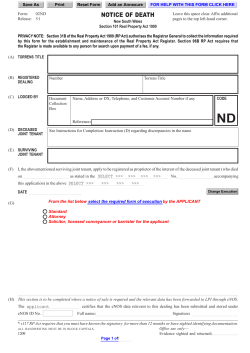


© Copyright 2026