
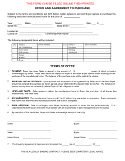
V-2000HD Assembly, Operating, and Maintenance Instructions for all V-2000 rotary presses.
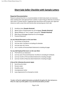
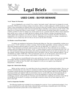
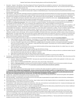
V-2000HD Assembly, Operating, and Maintenance Instructions for all V-2000 rotary presses. This manual contains the following documents: • Setup Guide • Overall Assembly Picture Showing Part Numbers • V-2000 Printhead/Extension Arm Pictures / Part Numbers • Micro Registration Adjustment • Level & Off Contact Adjustment • Pallet Assembly • Detent Wheel Adjustment & Service Pan Installation • Lubrication/Maintenance • 01-00-017 Warranty V-2000 Press • 01-00-006 Warranty Summary • 01-00-015 Terms And Conditions Serial Number: Date:____/____/______ (Please log your machine's serial number and date of purchase for future reference.) Vastex International, Inc. 1032 N. Irving St. Allentown, Pa. 18109 USA Phone# 610 434-6004 Fax# 610 434-6607 Web Site www.vastex.com E-Mail [email protected] NOTES V-2000HD Printer Introduction: Thank you for purchasing your printing equipment from Vastex International Inc. Vastex has been designing and building printing equipment since 1960. We have knowledge and experience, and are proud to supply the printing industry with quality equipment at an affordable price. You can be confident your purchase will give you years of trouble free service. Features: • Micro Registration • Steel pallets with rubber tops • All heads down • Upgradeable (Available up to 10x10 with 25 year warranty) • Tabletop units available Options: • Additional color and station upgrade packages • Unique, fast, numbering system attachment • Super heavy duty print arms (hold up to 50lbs.[22.7kg] or numbering system) • Pallets: leg, short leg, sleeve, short sleeve, mini, junior, oversized, jumbo, umbrella, vacuum, and custom sizes available • Side clamps, removable or fixed • Stand (for tabletop version) • Locking casters and levelers • Service Pan (for extra storage) w/ locking casters Vastex E-mail assistance Purchasing & Product Info: [email protected] Electrical Support: [email protected] Tech Support, Mechanical Setup, and Operation [email protected] Screen Printing Issues & Support: [email protected] 1 V-2000HD Setup Guide Note: Report any box damage to the driver and note it on the ticket before signing. If hidden damage is found, report it to the trucking company right away and save the packaging. 1) Remove straps, sides of crate, and shrink wrap from around the press. Remove lag bolts holding the rotor arms to skid and unpack boxes under press. 2) Take press off of skid, by removing the lag bolts at the feet and carefully sliding the press off the skid and onto the shop floor. Some accessories are packed with the press. 3) Install the gas springs, found in print head box with the number 1 head and the rotor arm bolts. There are 4 slots on each side to choose Be sure the barrel is in the up position and for starters use the slots shown to the right. 4) Note position of gas spring. Note: The gas spring can be put into any slots to get the “feel” you like. Be sure to install with the barrel up as shown. Install your rotor arms. Hook rotor arms over the tabs on top of the rotor hub Be sure to put the arms into the correct numbered positions. The 3/8 x 3/4 Rotor Hub long bolts, and lock washers, are located in the box with head #1. After hooking the arm into place you must lift and jiggle the arm while finding the threads for the bolts. The top right and bottom left are the locator bolts and should be installed first. Do not tighten any bolts until all four are started with at least two full turns. Locator bolts! 2 Rotor arm installed V-2000HD Setup Guide 5) Pallet Arm Assemble the pallets onto the pallet arms. See page 10 of your manual for step by step instructions. The #1 pallet has been assembled and leveled at the factory and it will mount onto rotor arm #1. Pallet 6) Install the pallets onto the rotor arms. Install the knob and corner clamp washer onto the pallet arm as shown in the picture below. If your machine came with them, install the retainer clip into the Corner Clamp Washer on the outside of the pallet arm. Slide the Pallet arm with corner clamp washer over rotor arm (pictured to the right), and hand tighten the corner clamp at the desired position. See page 9 for leveling information and instructions. Pallet Arm Rotor Arm Corner Clamp Washer Pallet Leveling Bolts Corner Clamp Knob Corner Clamp Washer 7) Install the print heads. One print head has been leveled and numbered #1 to match the swivel and extension arm #1. Remove the 2 bolts on the swivel arms, install the print head as shown, then return the bolts to the same holes. Be sure the head is slid all the way down in the slots. *The bolts for head #1 can be tightened but leave the others loose for now. Print Head Installed Swivel Arm. Remove these bolts before installing the print heads 3 Extension Arm V-2000HD Setup Guide Now it’s time to adjust the pallets! The objective is: To make the pallets and print heads aligned and parallel with approximately 1/8 off contact. You do not need to use a bubble level on the pallets. You can level the machine to the floor if you like, but the important thing is the pallets need to be parallel to the screen mounted in the print head and centered over the rotor arms. Remember the pallet #1 and print head #1 were adjusted at the factory. What we will do in the next few sections is use print head #1 to adjust the remaining pallets then use the pallets to adjust the remaining print heads. IMPORTANT NOTE: It is best to line up the inside of the screen with the front of the clamp bar any time you install screens in your V-2000 rear clamps. See page 5 for an example. 8) Place your best flat aluminum screen into head #1 and lower it over pallet #1. Align side of screen with side of pallet as shown. Do not remove this screen until all pallets have been set. 1/8 between screen and pallet at all corners Align side of screen with side of # 1 pallet. Be sure the gas spring is in a position that allows the screen to stay down by itself. Observe the “off contact” in all four corners of the pallet. It should be approximately 1/8”. These nuts should have been tightened at pallet assembly. Pallet leveling bolts & nuts #1 Rotor Arm, Pallet, & Print Head Shown Above 9a) Next lower the # 1 print head with the already installed screen over another pallet. The pallet leveling nuts should be finger tight while setting side alignment and off contact. Align the side of the pallet to the side of screen. Do not move the screen to the pallet, move the pallet to the screen. Adjust the nuts at the bottom of the pallet leveling bolts to set the off contact to approximately 1/8”. When 1/8” off contact has been achieved at all corners and the pallet and screen sides are flush proceed to tighten all pallet nuts. It is important that a good quality flat screen is used while making these adjustments. 9b) Repeat for all remaining pallets. 4 V-2000HD Setup Guide 10) Adjusting the remaining Print Heads. Move the screen to remaining print head positions and set the 1/8” off contact to the now leveled pallets. Don’t forget print head #1 was adjusted at the factory. But you may still have to make an adjustment due to variations in screens and possible movement in shipping. Please adjust the print head in this case not the pallet. Clamp a flat screen into a print head. Using the “Front/Rear Pitch” knobs and the “Left/Right Pitch” knobs, adjust the screen gap or “off contact” to 1/8”. Please read the notes below before adjusting the off contact. A. Be sure the “Micro Clamp Levers” are tight before leveling heads. B. When adjusting off contact or left/right pitch, loosen one “Main Head Bolt” at a time. C. Before adjusting the “Front/Rear Pitch Knob” be sure to loosen the “Front/Rear Lock” screw. Main Head Bolts: Front/Rear Pitch Knob Loosen to adjust off contact and left/right pitch Front/Rear Lock Left Pitch Knob Right Pitch Knob Screen Clamp Screen Clamp Keep Inside of Screen and Clamp Bar flush! 5 MICRO CLAMP LEVERS: Lift and rotate to a comfortable position. Only loosen and tighten levers while the head is in the down position. 6 VSP-WS Service Pan and Wheel Set for V-2000 (optional) VR-ARM-S Rotor Arm Assembly Detent Assembly VC-PH-SC Print Head Side Clamp (optional) VC-PH-RC Print Head Rear Clamp (pictured/standard) V-STAND (stand assembly 4,6,8 color press) (pictured) V-STAND-10 (stand assembly 10 color press) VC-HUB-4,6,8, or 10 C-Hub VR-HUB-4,6,8, or 10 Rotor Hub Note: Machine pictured is a 4 color 4 station press with one arm removed for pictures only. Also shown with optional Service pan and wheels. V2P-1517 15"X17" Standard Pallet assembly. *VC-EX-SHD Extension Arm Super Heavy Duty. (optional, required for numbering system) VC-EX-HD Extension Arm Heavy Duty V-2000HD Overall Assembly V-2000HD Overall Assembly VC-PH-RC Screen Clamp Weldment (2) 05-05-013-1 7 Fork Retainer (2) 05-05-026-0 Clamp Bar 05-05-022-0 (Micro Knob) Knob w/ Stud 3/8-16 x 2 1/4 (3) 04-05-150 Ground Plate 05-05-010-1 Micro Lock Clamp Levers (2) 04-05-145 Clamp Knob (2) 04-05-107 Spring, Micro Knob (3) 04-05-208 Screen Cab 05-05-011-1 Micro Wear Strip (4) 05-05-017 Vastex V-2000HD Print head/Extension Arm Spring (2) 04-05-072 Spring, Micro (3) 04-05-070 Registration Bar Mount 05-04-004-1A Support, Registration Bar Mount 05-04-021 Registration Bar 05-04-005 Gas Spring 04-00-001 Gas Spring Pin 05-05-018 Moving Point Spring Bracket 05-05-006 Swivel Arm 05-05-005-1 Knob, Long neck 04-05-191 VC-EX-HD Knob, Off Contact (2) 04-05-155 Hinge Weldment 05-05-001-1 Vastex V-2000HD Print head/Extension Arm Micro Registration Adjustment Instructions Vastex micro-registration is standard with every V-2000 screen printer. It uses three control knobs, two micro clamp levers, and three return springs for movement control. A set of centering sites is used to start at a zero point. A total of 1/2" movement is available in the "X" direction and also in the "Y" direction • Rotating the screen can be done by turning one of the "Y" micro control knobs. The pivot point for rotation is the tip of the other "Y" micro control knob. • The micro clamp levers must be loosened (1/4-1/2) turn only, before turning the control knobs. Start each job with the centering sites lined up. This ensures you will have all the available adjustment. To Move the Screen Left to Right To Move the Screen Front to Back or Rotate 1) Loosen the two micro clamp levers (1/4-1/2) turn 2) Turn the "X" micro control knob clockwise (looking at the head) to move the screen to the right. Turn it counterclockwise to move the screen to the left. 3) Tighten the micro clamp levers and check the position. Repeat the above steps if necessary until the desired position is achieved. Note: The micro clamp levers may be lifted and rotated to any position desired. They must be down to be loosened or tightened. 1) Loosen the two micro clamp levers (1/4-1/2) turn. 2) Turn both "Y" micro control knobs clockwise (looking at the head) to move the screen toward you. Turn them counterclockwise to move the screen away from you. Turn one or the other to rotate the screen. 3) Tighten the micro clamp levers and check the position. Repeat the above steps, if necessary, until the desired position is achieved. "Y" Micro Control Knob "Y" Micro Control Knob Micro Clamp Levers "X" Micro Control Knob Centering sites "X" Direction "Y" Direction Rotate 8 Level & Off Contact Adjustments • • • The Vastex V-2000 comes standard with 6-way level adjustments. The #1 head on your machine was leveled at the factory. NOTE: The Head Locking Bolts should only be loosened slightly, 1/2 turn at most with supplied 9/16" wrench, when adjusting the left to right pitch or off contact. Tighten fully after adjustments are finished. Thumb Screw Off Contact Knobs Head Lock Bolts Pitch Knob (red) Left/Right Pitch Micro Camp Levers To Adjust the Level of Your Screen: • Be sure you're screen is clamped tightly and both the micro clamp levers and head bolts are tight. • There are two sets of adjustments: (1) The Off Contact Knobs control left to right level as well as screen off contact. The Head Lock Bolt, located in front of each knob, must be loosened 1/4 turn before making this adjustment. Note: Always do one side at a time. (2) The red Pitch Knob controls the front to back level. The Thumb Screw must be loosened to make this adjustment. Do not over tighten. Follow these steps for each head. Head #1 is factory set. 1) Lower the print head to be leveled and be sure it is locked down completely. The screen should not be touching the pallet. 2) If the screen is touching the pallet in one corner or more loosen one Head Lock Bolt one at a time and turn the Off Contact Knobs clockwise to lift the screen off the pallet. Continue each side until the screen is level left to right and about 1/8” off the pallet. (If the front of the screen is contacting the pallet it may be necessary to jump to step 3) to pull it up to level or above in order to complete this step.) 3) Adjust the front to rear level by unlocking the Thumb Screw and turning the Pitch Knob. Clockwise will lift the front of the screen and counter clockwise will lower. (It may be necessary to repeat step 2 after adjusting the front to rear pitch.) Front/Rear Pitch Be sure to Tighten the Head Lock Bolts when finished adjusting. Off Contact 9 10 (2) Self Tapping Screws 2" (4) Lower Nuts Nuts Washers Doc# 01-08-024C Use these two nuts to level the pallet. 1/8" Head of bolt 6) Install the pallet assembly onto the press rotor arm. Refer to the Setup Guide section of the V-2000 manual for adjusting the pallet. Retainer Clip Corner Clamp Washer Nuts Pallet Arm Corner Clamp Knob 5) If you will be using a neck guide, install it now. It is installed with two self tapping screws as shown in the picture below. 4) Tighten all Lower Nuts. 3) Place the pallet arm on top of the washers as shown in the picture below. Install remaining nuts and washers on all four bolts but leave them loose for pallet leveling. 2) Set the height of the top nuts to approx. 2" from the bottom of the pallet, as shown to the right. 1) Install the nuts and washers as shown to the right. Do not fully tighten the lower nuts. Vastex Pallet Assembly Instructions Detent Wheel Adjustment Detent Rocker Assembly Doc #: 01-08-034 The Detent Wheel is adjustable. To adjust; Loosen the nut, with (2) 9/16 wrenches. Move the wheel up, to increase, or down, to decrease, the Rotor Arm holding pressure. The Detent Rocker is used to achieve a repeatable position for the pallet under your flash. It can be set to lock the arm very firmly, loosely, or can be disabled all together to remove the indexing feature. Service Pan and Wheels (optional) Wheels are installed with 1/2” hardware and foot brace. The brace goes under the foot and the wheel goes through both the foot and brace (shown below). Use the 1/2” lock washer and nut to attach the wheels to the feet. Service Pan is installed by laying the Pan on the floor and rolling the machine over the Service Pan. The Service Pan can also be installed by removing one wheel (must have two people for this). Line it up with the holes on the inside of the press’ feet. Lift the pan and install 1/2” hardware, using the flat washer on the bottom of the Service Pan 11 Lubrication and Maintenance **Your V-2000HD Press comes with a small bottle of oil, and a tube of grease to maintain your press properly. Please follow all Lubrication instructions to prevent premature wear ** Lubrication Main center column bearings can be lubricated with a light oil. Apply oil through the small hole in the top cap at the top center of your machine. This cap holds the top bearing down which pre-loads all the center bearings. Oil will drip down and lubricate all four bearings. Once per month (under normal daily use) approximately 1/2 oz. of light machine oil can be squirted into the hole. Apply 1/4 oz. and then spin both hubs. Apply the second half and then spin both hubs again. In time oil may be detected seeping out from beneath the lowest bearing and above the stand center box. Clean off as needed. The Extension arm Hinge can also be oiled through the small hole on the side of the hinge. A dab of grease should be applied to the wear plates at the end of the micro-registration control knobs. This can be applied monthly or as often as needed. A spot of grease on every adjustment bolt or knob thread will prolong their life. Particularly the Micro Control Knobs, Micro Clamp Levers, and the Screen Clamp threads. The gas spring pins should be sprayed or dripped with oil once per month. Squirt oil in hinge The Center Bearings' oil hole is shown below. Extension Arm Hinge Cleaning Clean your machine on a daily basis or between each job. Particularly removing lint around moving points and adjustment areas. A clean machine is more likely to be maintained properly than a messy one. Any solvents can be used on the pallet tops for cleaning. The painted surfaces should be cleaned with detergent, like a glass or multi-surface cleaner, to remove lint and dust. Mineral spirits can be used to remove spilled inks. Avoid spraying pallet adhesive on the gas springs to ensure their longevity. Inspection Inspect your machine on a monthly basis for untimely wear or any other signs of problems. This can be done while lubricating and should take no more than a few minutes. Finding a problem early can reduce the cost of downtime and repair. 12 Vastex Warranty for V-2000HD Series Manual Printer Doc#01-00-017 Vastex, hereinafter referred to as “seller” warrants only to its “purchaser”, who holds a copy of the original invoice and is the original end user of the equipment in question, its new equipment against defects in workmanship on a pro-rated basis for a period of twenty five (25) years from the date of shipment to buyer and receipt of payment in full. Replacement parts are covered for a period of (1) year from ship date or for the remainder of the original 25 year warranty, whichever is longer, contingent on payment in full. This warranty is expressly contingent upon the buyer delivering to seller, at the address below, with all transportation charges prepaid, the part or parts claimed to be defective within the above mentioned period for new equipment and replacement parts. In order to expedite the movement of parts and to minimize down time to the buyer, the replacement part shall be supplied on a C.O.D. basis. If testing and analysis of said part by the seller or its supplier discloses that said part is defective, the cost of said part will be refunded to the buyer on a pro-rated basis. Except as otherwise provided herein, the equipment is being sold “as-is”. Final determination of the suitability of the equipment for the use contemplated by the buyer, is the sole responsibility of buyer, and seller shall have no responsibility in connection with the suitability. All warranties implied by law, including the implied warranties of merchantability and fitness are hereby limited to workmanship and defective parts to a period of (25) years (for new equipment) and (1) year (for replacement parts) after date of shipment to first buyer. The express warranty and remedies contained herein and such implied limited warranties are made solely to the sole warranties and remedies and are in lieu of all other warranties, guarantees, agreements, and other liabilities, whether express or implied, and all other remedies for breach of warranty or any other liability of seller, in no event shall seller be liable for consequential damages. Vastex will repair or replace any part of the original machine that is deemed defective or fails during the above mentioned time, due to poor workmanship, with the exception of gas springs and rubber mats. Examples of poor workmanship are welds, bearings, threads, knobs, fasteners, and general machine fatigue. The part must be shipped back to Vastex to be inspected at the shipper’s cost. If it is determined to be defective due to workmanship or normal wear, it will be repaired or replaced and shipped within 2 business days. The repaired part will be sent back ground carrier, freight prepaid if within 3 years of the original purchase and if in the continental US. After 3 years or if outside the continental US, parts will be shipped back per customers’ instructions, freight collect. If the exact part to be replaced is not available, a replacement part will be supplied that will perform within original design parameters. No person, agent, distributer, or service representative is authorized to change, modify or extend the terms hereof in any manner whatsoever. These terms and conditions are an essential part of the transaction between the parties and constitute the entire agreement between them with respect to the same. Some states do not allow limitation on how long an implied warranty lasts of the exclusion or limitation of incidental, or consequential damages, so the above limitation may not apply to you. This warranty gives you specific legal rights, and you may also have other rights which vary from state to state. Please refer to doc. 01-01-006 for warranty implementation help. Please refer to doc. 01-00-015 for specific terms and conditions of sale and the limited warranty. This warranty effective as of 07/01/01 F:\Shared\Vastex\01-Manuals & Doc\00-misc\01-00-017 (V2000-HD Warranty).wpd VASTEX INTERNATIONAL 1032 N. IRVING ST. ALLENTOWN PA. 18109 USA 13 VASTEX WARRANTY IMPLEMENTATION SHEET Please read this document in order to fully understand the warranty. Doc.# 01-00-006 Your new Vastex equipment is protected against *manufacturers’ defects by our warranty, completely explained in doc# 01-00-017 for the V2000-HD series manual printer and in doc# 01-00-005 for all other Vastex manufactured equipment. Please refer to these documents for the **warranty term and specific concerns about the warranty. The following are some important facts and requirements for the proper implementation of the warranty. 1.0 Everything is covered! 2.0 **Warranty Term is defined as: Ship date from VASTEX to the date the item in question is returned to VASTEX for inspection and repair. 3.0 *Manufacturers defects are defined as: Parts determined to be defective in workmanship which will lead up to a premature failure. The determination will be made only by the manufacturer of the item in question. 4.0 To take advantage of the warranty the following steps must be taken: 4.1 The equipment must be paid for in full. 4.2 The item in question must be shipped to VASTEX for evaluation with all shipping costs incurred by the buyer. 4.3 If the item is deemed as a manufacturer’s defect it will be repaired or replaced within 2 business days from the time received. The shipping cost back to the customer located in the continental United States will be paid by VASTEX if a warranty item. 4.4 If the item in question must be replaced immediately and is more than a year old, it will have to be purchased at list price and will be shipped COD. A pro-rated credit will be given promptly if the returned item is a valid manufacturer’s defect. 4.5 If the equipment was shipped less than a year before the date of the service call and a technician confirms the part needed for repair, the replacement will be shipped before the replacement is shipped back. An RGA will be issued and must accompany the old part to VASTEX within 30 days or the account will be billed. 5.0 Important facts about the condition of shipped equipment: 5.1 Dryers are partially assembled with the belts tracked and the machine run at full temperature for a min. of 1 ½ hours. 5.2 Printers are partially assembled, inspected, and adjusted for all heads down prior to partial disassembly and packing. 5.3 Exposing units are fully assembled and tested with the maximum screen size for vacuum integrity, timer operation and light output. 6.0 This document is in addition to the standard warranty and only helps the customer understand how to take advantage of the warranty. In no way does this document override the standard warranty or the terms and conditions of sale and the limited warranty doc# 01-00-015. Please see doc# 01-00-015 for specific terms and conditions of sale and the limited warranty VASTEX INTERNATIONAL 1032 N. IRVING ST. ALLENTOWN PA. 18109 USA F:\Shared\Vastex\01-Manuals & Doc\00-misc\01-00-006 (Warranty Implementation).wpd 14 Vastex International, Inc. TERMS AND CONDITIONS OF SALE AND LIMITED WARRANTY Doc.#01-00-015 1. Buyer’s order will constitute an offer in accordance with the terms hereof and such offer, upon acknowledgment of Seller, will constitute the agreement between Buyer and Seller. Buyer’s order after such acknowledgment by Seller will not be subject to cancellation, change or reduction in amount, or suspension by Buyer of deliveries, unless prior to such action Buyer has obtained Seller’s written consent. Notwithstanding anything to the contrary in Buyer’s Purchase Order or other communications, the parties agree to be bound by these Terms and Conditions. Acceptance of the product by the Buyer shall be deemed to constitute unconditional acceptance of these Terms and Conditions. 2. Any of these terms, conditions and provisions of Buyer’s order which are inconsistent with Seller’s acknowledgment and these Terms and Conditions of Sale shall not be binding on the Seller and shall be considered not applicable to any sale so made. No waiver, alteration or modification of any of the provisions on either side of the document shall be binding upon Seller unless agreed to in writing by Seller. 3. (a) All prices are F.O.B. Seller’s Plant and method of delivery and routing shall be at Seller’s discretion, unless specifically otherwise stated herein. Notwithstanding any agreement to pay freight, delivery of products purchased hereunder to a common carrier or licensed trucker shall constitute delivery to Buyer and be determinative of the date and time of shipment and all risk of loss or damage in transit shall be borne by Buyer. If the Buyer fails to accept the goods from the common carrier or licensed trucker, the Seller shall be entitled to claim payment from the Buyer. Seller shall arrange for storage, the risk and the cost, including insurance costs, to be borne by the Buyer (and Buyer agrees to pay such amounts upon demand) except if the failure to accept delivery is due to any of the exceptions noted in Paragraph 4. (b) Terms of payment shall be as stated on invoice. 4. It is understood that deliveries will be made in accordance with Seller’s regular production schedule. Every reasonable effort will be made to meet the Buyer’s required delivery dates but Seller will not be liable for damages or be deemed to be in default by reason of any failure to deliver or delay in delivery due to any preference, priority, allocation or allotment order issued by the Government, whether Federal, State or local, or causes beyond its control including but not limited to, Acts of God or a public enemy, acts of Government, fires, floods, epidemics, quarantine restrictions, strikes, lockouts, freight embargoes, severe weather, unavailability of materials or shipping space, delays of carriers or suppliers or delays of any subcontractors. Should delay in delivery be caused by any of the circumstances mentioned in this paragraph, such extension of the delivery period shall be granted as is reasonable under the circumstanced of the case. Should delay be caused by an event not specifically mentioned in this paragraph, damages will be limited to cancellation of the purchase order without penalty, and refund of any monies deposited or prepaid on the purchase order with no liability for any consequential or incidental damages. 5. Seller reserves the right to increase the prices prior to Seller’s acceptance of order and/or after expiration of any price quoted by Seller. 6. Unless otherwise stated in writing, Seller’s prices do not include sales, excise, value-added or other taxes. Consequently, in addition to the price specified herein, the amount of any present or future sales, use, excise, value-added or other tax applicable to the manufacture, sale, purchase or use of the products hereunder shall be paid by Buyer, or in lieu thereof, Buyer shall provide Seller with a valid tax exemption certificate acceptable to the taxing authorities. 7. Seller reserves the right, at any time, to revoke any credit extended to Buyer because of Buyer’s failure to pay for any products when due or for any other reason deemed good and sufficient by Seller and in such event, all subsequent shipments shall be paid for prior to at delivery at Seller’s option. 8. (a) SELLER’S LIABILITY SHALL BE LIMITED TO SELLER’S STATED SELLING PRICE PER UNIT OF ANY DEFECTIVE GOODS AND SHALL IN NO EVENT INCLUDE BUYER’S MANUFACTURING COSTS, LOST PROFITS, GOODWILL, OR ANY OTHER SPECIAL, INDIRECT, INCIDENTAL OR CONSEQUENTIAL DAMAGES, ARISING OUT OF THE AGREEMENT, THIS CONTRACT, THE SALE OF THE PRODUCTS TO THE BUYER OR THE USE OR THE PERFORMANCE OF THE PRODUCTS. Seller may at its discretion repair, replace or give the Buyer credit (pro-rated) for such defective products. (b) Notwithstanding anything herein to the contrary, Seller shall have no liability for alleged defects with the products which are not specified in written notice from the Buyer to the Seller within thirty-six (36) months from the date of shipment of machines. Seller shall pass to Buyer any warranty received by Seller from the manufacturer of Limited Life Components, which in most cases is 12 to 18 months. (c) Seller shall have no liability under this Limited Warranty unless Buyer has paid in full for the products. Further, this Limited Warranty is expressly contingent on Buyer’s delivery to Seller, all costs prepaid, the defective part(s) within thirty-six (36) months of shipment to Buyer, together with a written statement specifying the alleged defect(s). Any replacement part(s) shall be shipped to Buyer on a C.O.D. basis. (d) SELLER SPECIFICALLY EXCLUDES ALL WARRANTIES, EXPRESSED, IMPLIED OR OTHERWISE, EXCEPT AS STATED EXPLICITLY IN THESE TERMS AND CONDITIONS OF SALE. SELLER DISCLAIMS THE WARRANTY OF MERCHANTABILITY AND FITNESS FOR A PARTICULAR PURPOSE. 9. The remedies herein reserved by Seller shall be cumulative and in addition to any other legal remedies. No waiver of a breach of any portion of this contract shall constitute a waiver of continuing or future breach of such provision or of any other provisions hereof. 10. These Terms and Conditions constitute the entire agreement of the parties. No amendments, changes, revisions or discharges hereof in whole or in part shall have any force or effect unless set forth in writing and signed by the parties hereto. This contract shall not be assignable by Buyer voluntarily by operation of law or otherwise without Seller’s written consent. 11. This contract shall be governed and shall be construed according to the domestic laws of the Commonwealth of Pennsylvania. 12. Anything herein to the contrary notwithstanding, any action for alleged breach by Seller of the contract between the parties, including but not limited to any action for breach of the warranties herein set forth, shall be barred unless commenced by Buyer within one (1) year from the date such cause of action accrued. 13. This agreement shall inure to the benefit of and be binding upon the parties hereto, their respective successors and permitted assigns. 14. All notices required by this contract to be given by either party shall be sent in writing or by facsimile and shall be addressed to the last known address of such other party. Notices shall be deemed to have been received on the fifth business day following deposit in the mail. M:\Vastex\01-Manuals & Doc\00-misc\01-00-015 TERMS&CONDITIONS.wpd 15


© Copyright 2026