
Document 256637
Access 5 Project Office
NASA
P.O. Box 273
Edwards, CA 93523 USA
661-276-2440
661-276-3880 FAX
www.access5.aero
COVER SHEET
Access 5 Project Deliverable
Deliverable Number: IMP006
Title: Composite Report on FAA Flight Plan and Operational Evaluation Plan, Version 7.0
Filename: IMP008_Composite Rpt on FAA Flight Plan and OEP 7.0_v1_FINAL.doc
Abstract:
The purpose of this document is to present the findings that resulted from a high-level
analysis and evaluation of the following documents:
− The OEP (Operational Evolution Plan) Version 7 – a 10-year plan for operational
improvements to increase capacity and efficiency in U.S. air travel and transport
and other use of domestic airspace. The OEP is the FAA commitment to
operational improvements. It is outcome driven, with clear lines of accountability
within FAA organizations. The OEP concentrates on operational solutions and
integrates safety, certification, procedures, staffing, equipment, avionics and
research;
− The Draft Flight Plan 2006 through 2010 – a multi-year strategic effort, setting a
course for the FAA through 2001, to provide the safest and most efficient air
transportation system in the world;
− The NAS System Architecture Version 5 – a blueprint for modernizing the NAS
and improving NAS services and capabilities through the year 2015; and
− The NAS-SR-1000 System Requirements Specification (NASSRS) – a
compilation of requirements which describe the operational capabilities for the
NAS.
The analysis is particularly focused on examining the documents for relevance to
existing and/or planned future UAV operations. The evaluation specifically focuses on
potential factors that could materially affect the development of a commercial ROA
industry, such as:
− Design limitations of the CNS/ATM system,
− Human limitations,
The information presented was taken from program specifications or program office lead
personnel.
.
Status:
SEIT-Approved
Limitations on use:
This document represents thoughts and ideas of the Implementation and Infrastructure work
package team. It has been reviewed and approved by the SEIT but has not been reviewed or
approved by the Project Office as official Access 5 Project recommendations on this subject.
2
Remotely Operated Aircraft (ROA) Impact on the
National Airspace System (NAS) Work Package,
2005
Composite Report on FAA Flight Plan &
Operational Evaluation Plan Version 7.0
The following document was prepared by a collaborative team through the noted work package. This was a
funded effort under the Access 5 Project.
3
TABLE OF CONTENT
1
EXECUTIVE SUMMARY ......................................................................................................... 7
2
PURPOSE .................................................................................................................................... 10
3
BACKGROUND......................................................................................................................... 10
3.1
3.2
3.3
3.4
4
HISTORICAL .............................................................................................................................. 10
POLICIES , PROCEDURES AND TECHNICAL STANDARDS ..................................................... 11
REMOTE PILOTS ....................................................................................................................... 11
SPECIAL COMMITTEE (SC) 203 ............................................................................................. 11
STATED ASSUMPTIONS........................................................................................................ 12
4.1.1
TRAFFIC FROM A TERMINAL PERSPECTIVE .......................................................................... 13
5
ROA POTENTIAL APPLICATIONS .................................................................................... 14
6
ATC AUTOMATION ................................................................................................................ 15
6.1 MICROPROCESSOR-EN ROUTE AUTOMATED RADAR TRACKING SYSTEM (MICROEARTS)............................................................................................................................................... 15
6.2 COMMON AUTOMATED RADAR TRACKING SYSTEM (ARTS) ........................................... 16
6.3 STANDARD TERMINAL AUTOMATION REPLACEMENT SYSTEM (STARS) ....................... 17
6.4 THE HOST COMPUTER SYSTEM (HCS) ................................................................................. 18
6.4.1 USER REQUEST EVALUATION TOOL (URET)....................................................................... 18
6.5 EN ROUTE AUTOMATION MODERNIZATION (ERAM)........................................................ 19
6.6 ADVANCED TECHNOLOGIES AND OCEANIC PROCEDURES (ATOP) ................................. 21
6.7 OPERATIONAL AND SUPPORTABILITY IMPLEMENTATION SYSTEM (OASIS) ................. 22
7
COMMUNICATIONS............................................................................................................... 24
7.1
7.2
7.3
7.4
7.4.1
7.4.2
7.4.3
7.5
7.6
NAS GROUND-GROUND INTERFACILITY COMMUNICATIONS ........................................... 25
NAS GROUND-GROUND COMMUNICATIONS RECONFIGURATION CAPABILITIES .......... 31
NAS AIR-GROUND COMMUNICATIONS ................................................................................ 32
NAS VOICE SWITCHING SYSTEMS ........................................................................................ 33
VOICE SWITCHING AND CONTROL SYSTEM (VSCS) ........................................................... 33
SMALL TOWER VOICE SWITCH (STVS)................................................................................ 33
RAPID DEPLOYMENT VOICE SWITCH (RDVS) ..................................................................... 34
ROA COMMUNICATIONS ........................................................................................................ 34
SATCOM KU-BAND CAPACITY ............................................................................................ 35
4
7.7 SATCOM KU-BAND AVAILABILITY ..................................................................................... 36
7.8 VHF DIGITAL LINK MODE 2 (VDL-2).................................................................................. 36
7.9 CONTROLLER-PILOT DATA LINK COMMUNICATIONS (CPDLC) ..................................... 37
7.10 NEXT GENERATION AIR/GROUND COMMUNICATION SYSTEM (NEXCOM) ................ 38
7.10.1 CHANNEL CAPACITY ............................................................................................................ 38
7.10.2 VHF DIGITAL LINK MODE 3 (VDL-3) ............................................................................... 38
7.10.3 A/G COMMUNICATIONS IMPROVEMENTS ........................................................................... 39
7.11 NAS TELECOMMUNICATIONS SERVICES EVOLVES .......................................................... 39
7.12 COMMUNICATIONS SYSTEMS SCALABILITY AND ARCHITECTURAL LIMITATIONS ...... 40
8
NAVIGATION AND WEATHER SYSTEMS ...................................................................... 41
8.1.1
9
WEATHER RADAR SYSTEMS ................................................................................................... 41
SURVEILLANCE SYSTEMS.................................................................................................. 43
9.1
9.1.1
9.1.2
9.1.3
9.2
9.3
9.4
9.5
ADS-B (AUTOMATIC DEPENDENT SURVEILLANCE-BROADCAST).................................... 44
FLIGHT INFORMATION SERVICES - BROADCAST (FIS-B) .................................................... 44
UNIVERSAL ACCESS TRANSCEIVER (UAT) .......................................................................... 45
MODE S ................................................................................................................................... 45
TRAFFIC INFORMATION SYSTEM-BROADCAST (TIS-B) ..................................................... 46
AIRPORT SURFACE DETECTION EQUIPMENT - MODEL 3 (ASDE-3) ................................ 47
AIRPORT SURFACE DETECTION EQUIPMENT - MODEL X (ASDE-X) .............................. 47
AIRPORT SURFACE DETECTION EQUIPMENT - MODEL 3X (ASDE-3X) .......................... 48
10 DOCUMENT SUMMARY ....................................................................................................... 49
11 RECOMMENDATIONS FOR FURTHER STUDY ............................................................ 50
11.1 MODELING .............................................................................................................................. 50
11.1.1 MODELING TOOL ENHANCEMENTS..................................................................................... 50
11.2 HUMAN IN THE LOOP SIMULATION .................................................................................... 50
11.2.1 RELOCATION MODELING TO SMALLER AND UNDERUTILIZED TERMINALS ..................... 50
11.2.2 MODELING AND SIMULATION OF ROA FLIGHT SCHEDULING .......................................... 51
11.2.3 AIR TRAFFIC CONTROLLERS AND CPDLC ......................................................................... 51
12 REFERENCE DOCUMENTS AND OTHER SOURCES CONSULTED........................ 52
12.1
12.2
12.3
FAA AND OTHER DOCUMENTS ............................................................................................ 52
WEBSITES USED IN THIS STUDY ............................................................................................ 53
INTERVIEWS ............................................................................................................................ 53
ACRONYMS ..................................................................................................................................... 54
5
LIST OF FIGURES
Figure 4-1. Domestic Large Carrier Emplanements ...................................................... 12
Figure 4-2. Commuter Emplanements .......................................................................... 13
Figure 6-1. FAA’s plan to transition from HCS to ERAM, FY 2005 to FY 2009 .......... 21
Figure 6-2. General View of OASIS............................................................................. 23
Figure 7-1. ATC Air Ground communications solution implementation ....................... 25
Figure 7-2 CPDLC Effects on Operations and Delays .................................................. 37
Figure 7-3. Simplified Representation of the NEXCOM System .................................. 38
Figure 9-1 Mode S Beam Dwell (2.4-Degrees) Target Limitations ............................... 46
LIST OF TABLES
Table 6-1. Micro-EARTS System Capacity Figures...................................................... 16
Table 6-2. ARTS IIE Scalability and Architectural Limitations .................................... 16
Table 6-3. ARTS IIIE Scalability and Architectural Limitations................................... 17
Table 6-4. STARS Scalability and Architectural Limits................................................ 17
Table 6-5. HCS Scalability and Architectural Limits .................................................... 18
Table 6-6. Number of Flight Plans URET Accomodates............................................... 19
Table 6-7. ERAM Scalability and Architectural Limits................................................. 20
Table 6-8. ATOP Scalability and Architectural Limits.................................................. 22
Table 7-1. Interfacility Direct-Access Voice Connectivity ............................................ 26
Table 7-2. Interfacility Direct-Access Backup Voice Connectivity ................................ 27
Table 7-3. Interfacility Indirect-Access Backup Voice Connectivity ............................. 28
Table 7-4. NAS Interfacility Data Communications Connectivity................................. 30
Table 7-5. Reconfiguration Capabilities ....................................................................... 32
Table 7-6. VSCS Scalability and Architectural Limits .................................................. 33
Table 7-7. Example of STVS Scalability and Architectural Limitations........................ 34
Table 7-8. RDVS Scalability and Architectural Limitations.......................................... 34
Table 7-9. Communications Systems Scalability and Architectural Limitations............ 40
Table 8-1. Air Traffic Volume Limitations for Weather Systems.................................. 42
Table 9-1. Air Traffic Volume Limitations for In Flight Primary Systems .................... 43
Table 9-2. Air Traffic Volume Limitations for In Flight Secondary Systems ................ 44
Table 9-3. ASDE-3A/AMASS Scalability and Architectural Limitations...................... 47
Table 9-4. ASDE-X Scalability and Architectural Limitations...................................... 48
Table 9-5. ASDE-3X Scalability and Architectural Limitations.................................... 48
6
1 EXECUTIVE SUMMARY
From an extremely simplistic assessment-level of the FAA Flight Plans of 2005 and 2006
(DRAFT), Unmanned Aerial Vehicles (UAV is FP terminology) are included under the
“Increased Safety Section” and book-marked within the General Aviation (GA) initiative.
Similarly, the FAA Business Plans 2005 identifies that the Regulation & Certification
Group will lead the UAV activities and the Air Traffic Organization will be in support.
The Operational Evolution Plan V 7.0 continues to stress overall NAS safety, capacity
and efficiency in the air and ground environment, however, it does leave “the door open”
for UAVs. This “door” is provided not in the quadrants dedicated to congestion and
efficiency but in the outer-rings identifying “Prototype & Pilot Projects” and/or “Safety,
Policy, Procedures & Airspace” and any new UAV initiative would be introduced by
industry representation through the appropriate RTCA committee.
Unfortunately this simplistic assessment is insufficient to really understand the UAVrelated relevance of the various FAA planning and funding documents and this report is
designed to provide both content and context in this regard.
From an Air Traffic Management (ATM) perspective the (total) integration of UAVs is
bound to cause some intellectual as well as technical and operational challenges, since
regulators and the ATM community have not yet had the opportunity to become
thoroughly familiar with the fundamentals of possible UAV integration and a baseline for
comparison with manned aircraft operations has not yet been fully explored.
Using the RTCA Concept of Operations & Future Vision for the Future of Aviation (Nov
15, 2002) as a baseline for consideration, we can identify some similarities with manned
aircraft operations and point out some definite differences.
The Con Ops vision “… is to allow users to make operational decisions based on their
own economic business case while enabling the safe, orderly and expeditious flow of air
traffic …to maximize benefits and achieve seamless operations”. It goes on to state, “…
aircraft operate along more efficient auto-negotiated four dimensional flight profiles.
Operations are increasingly aircraft-centric, focusing on performance rather than
equipment standards; with use of required navigation performance (RNP) as a key step in
enabling greater efficiency, flexibility and capacity enhancements.”
There is tacit recognition that the future ATM system will be data-driven and that the
adoption of a “system wide information management (SWIM)” will be required to
manage the complex and dynamic demands of the NAS stakeholders.
UAVs could impose an additional, unique set of considerations on a system that has been
constructed to support only humanly managed flight operations. The entire investment
7
strategy for NAS evolution is based upon the current airline-centric operational model of
point-to-point operations whereby ATC accommodates user-preferred routes whenever
possible. The name of the game is throughput by maximizing predictability and
flexibility and making the most of the current NAS capacity. The air traffic controller’s
work-load has increased with the overall shift from large jets to smaller regional jets and
the investment in ATC automation tools support this same concept of operations.
The obvious differences in UAV operations from manned aircraft operations are in three
main areas:
Flight Envelope & Performance – UAVs range from the micro (light weight) through to
roughly the size of a Boeing 737. There is a direct relationship between airframe size and
power-plant selected to achieve its operating role and mission requirements. UAVs have
widely varying power-plants, turbo-fan, turbo-propeller, normally aspirated gas engines;
and a few with hybrid solar or alternative fuel systems. In addition, the power output of
the electrical generators often dictates the equipment that can safely be powered,
including considerations for anti-icing and de-icing. The ratio of thrust to weight dictates
the rate of climb, maneuverability, service ceiling and the various operating speeds, just
the same as manned aircraft. Often these operating parameters are different from those of
the current NAS operators.
UAV Levels of Automation & Sophistication – the current UAVs in operation have
widely varying capabilities for C3 and other operational considerations, like the ability to
utilize RNP and Reduced Vertical Separation Minima (RVSM). Some UAVs rely on
human observers to provide a level to see (or sense) and avoid other traffic, others utilize
on-board electronic sensors. The C3 capabilities can range from basic line-of-sight
VHF/UHF to sophisticated satellite-based relay channels with associated back-up
systems. The flight management systems also vary widely and with the expectation that
“aircraft” will follow pre-defined four dimensional trajectories, in many cases some
accommodation for UAV must be expected.
Mission Profiles – the currents mission profiles anticipated for UAVs initially are for
homeland defense and border or port surveillance. The flight profile could entail a takeoff, not necessarily from a conventional runway, a climb and transit to a “target area”, a
change in altitude from high to low to medium, a loitering requirement and possibly a
return to base or onward transit to another destination. Recovery could entail a sky-hook,
or some other unconventional landing system. With the exception of transit flights, it is
envisaged that UAVs would be operated very rarely in the conventional point-to-point
manner for which the NAS is designed, funded and maintained/evolved.
FAA plans, including the Operational Evolution Plan, the Flight Plan, the NAS System
Architecture, and the NAS System Requirements Specifications have been examined to
safely expand the use of UAVs and understand potential effects of the development of a
commercial UAV industry.
8
Of particular interest are design and/or human limitations and their impact on the ability
to meet NAS communications, navigation, surveillance, and air traffic management
requirements in the light of the vast array of systems and tools in use today.
It can be anticipated that air traffic will increase as UAV applications become more
pervasive; and newer systems will replace capacity-constrained, older technology
systems to more safely accommodate the larger volume of air traffic in the NAS.
Surveillance and automation systems such as ADS-B, ASDE-X, STARS, ERAM, and
ATOP, together with new voice and data communications platforms, will develop
enhanced capacity to meet NAS requirements for the 21st century.
New strategies, methods and tools for handling traffic flow, such as URET, will also need
to be devised to adapt to the higher volume, safety levels and reduced separation
demanded in the future. To this end, recommendations for further study in the areas of
modeling, decentralizing and relocation of facilities are also made in this document.
A high performance air transportation system supports our objective of fueling our
economy by allowing access to a wide range of private, commercial, civil and military
aviation users, while remaining the world’s safest form of transportation.
As an FAA executive has remarked in many a public forum, the FAA consider safety as
their priority/benchmark for operating the NAS and will endeavor to introduce UAVs in a
manner that first, “does no harm”; and the approach adopted by the FAA to this challenge
will be “prudent, pragmatic and progressive”!
It is clear from the structured analysis of the various FAA investment documents
examined in this work package that UAVs can be successfully introduced to the NAS if
the Access 5 program continues to provide the empirical data required to substantiate the
conclusions being drawn by the project and resulting in recommendations to the FAA.
Given that the NAS has now surpassed the pre-2001 levels of traffic and placing
increasing demands on what is overall a thirty-year old infrastructure, these documents
identify an investment strategy that is heavily reliant on total system automation. This
underlying theme must be factored into future Access 5 activities if it to stay aligned with
how the NAS will be funded, evolved and operated in the years to come.
Note:
It should be noted that the nomenclature related to the term Unmanned Aerial Vehicle
(UAV), Remotely Operated Aircraft (ROA) and Unmanned Aircraft System (UAS) are
used interchangeably to reflect the genre and vintage of the various documents studied
and/or referred to.
9
2 PURPOSE
The purpose of this document is to present the findings that resulted from a high-level
analysis and evaluation of the following documents:
− The OEP (Operational Evolution Plan) Version 7 – a 10-year plan for operational
improvements to increase capacity and efficiency in U.S. air travel and transport
and other use of domestic airspace. The OEP is the FAA commitment to
operational improvements. It is outcome driven, with clear lines of accountability
within FAA organizations. The OEP concentrates on operational solutions and
integrates safety, certification, procedures, staffing, equipment, avionics and
research;
− The Draft Flight Plan 2006 through 2010 – a multi-year strategic effort, setting a
course for the FAA through 2001, to provide the safest and most efficient air
transportation system in the world;
− The NAS System Architecture Version 5 – a blueprint for modernizing the NAS
and improving NAS services and capabilities through the year 2015; and
− The NAS-SR-1000 System Requirements Specification (NASSRS) – a
compilation of requirements which describe the operational capabilities for the
NAS.
The analysis is particularly focused on examining the documents for relevance to
existing and/or planned future UAV operations. The evaluation specifically focuses on
potential factors that could materially affect the development of a commercial ROA
industry, such as:
−
Design limitations of the CNS/ATM system,
−
Human limitations,
The information presented was taken from program specifications or program office lead
personnel.
3 BACKGROUND
3.1
Historical
10
In the late 1970s the FAA and DoD jointly developed criteria that enabled ROA to
operate outside restricted area airspace. Initial ROA systems were small and operated in
proximity to the operator. The advent of the Predator ROA in 1995 expanded the scope
of ROA operations to greater distances and higher altitudes. The arrival of the Global
Hawk ROA in 1998 stretched the bounds of operation to the international arena.
Increasingly, air space capacity and safety issues are becoming of major importance as
rapidly growing unmanned flight activity is anticipated.
3.2
Policies, Procedures and Technical Standards
NASA's High-Altitude, Long-Endurance Remotely Operated Aircraft in the National
Airspace System (HALE ROA in the NAS) project was established in 2004 to develop
policies, procedures and technical standards to enable remotely or autonomously operated
aircraft to fly reliably and routinely in civil airspace with an equivalent level of safety as
planes flown by on-board pilots. The project forms the core of the government-industry
Access 5 project, bringing together NASA, the FAA, the DoD, the Department of
Homeland Security (DHS) and the UAV National Industry Team (UNITE) to integrate
ROAs into the national airspace.
3.3
Remote Pilots
Remote pilots operate ROAs from distant vantage locations that may either be fixed or
mobile, and are equipped with advanced technological means to achieve mission
objectives. The remote pilots typically require communications capacity to remotely
operate aircraft controls and equipment, and successfully conduct routine or special flight
activities. Remote pilots make extensive use of traditional flight methods and techniques,
air navigation, meteorology, flying directives, and aircraft operating procedures,
throughout short or extended flights, from locations often coordinated to be
geographically distant from the aircraft being flown.
As expected, for certain flight segments, remote pilots rely extensively on air traffic
controllers as well as automated air traffic control systems, locally available to the
aircraft. To achieve this end, the remote pilots communicate with air traffic controllers
either through the use of a “bent pipe” (Pilot-to-ROA-to-air traffic controller), or
possibly, through the use of the PSTN (Public Switched Telephone Network) or cellular
telephone networks.
3.4
Special Committee (SC) 203
Standards associated with ROAs, with safety being a primary emphasis, are being
developed by SC203, with the active involvement of all impacted FAA lines of business.
11
4 STATED ASSUMPTIONS
The evaluation of NAS subsystem design limits must be assessed based on NAS traffic
models and traffic added by ROA operations.
Main assumptions made in this document are based on a model that shows that air traffic
volumes will increase significantly as ROA applications and operations become more
common and widespread – in other words, ROA operations do not displace manned flight
operations but add to it. Consequently, the effects of vast increases in air traffic volume
are examined – most particularly on air traffic controllers – as well as on surveillance,
communications, and automation systems. The impact ROA traffic will have on Air
Traffic Controllers and Communications, Navigation, Surveillance / Air Traffic
Management (CNS/ATM) are examined next.
Excerpts from the “FAA Forecast Fact Sheet Fiscal Years 2004-2015” [ 1], are provided
in Figure 4-1 and Figure 4-2.
Millions
1,000
Mar-01
900
Mar-02
Mar-03
800
700
600
500
Return to pre 9/11
levels in 2006
400
300
96
98
00
02
04
06
08
10
12
14
Figure 4-1. Domestic Large Carrier Emplanements
12
Millions
180
Mar-01
160
Mar-02
Mar-03
140
120
100
80
60
40
96
98
00
02
04
06
08
10
12
14
Figure 4-2. Commuter Enplanement
4.1.1 Traffic from a Terminal Perspective
Increased airspace capacity around major airports, reducing delays and improving air
safety requires high performance/capacity surveillance systems coupled with high levels
of automation. Based on current technology, for a given geographic area, airspace
capacity around terminal areas are sometimes augmented by commissioning multiple
runways.
Under FAA current regulations, a new runway can allow at least 30 to 40 more
operations per hour. Therefore, airport capacity to handle air traffic is a function of
airport size, runway layout, air traffic patterns (both arriving and departing), ambient
weather conditions, and the time frame in which a surge of traffic must be dealt with.
13
5 ROA POTENTIAL APPLICATIONS
Based on sensor and other developments recently seen, ROA applications likely to be
deployed on large scales are:
−
−
−
−
−
−
−
−
−
−
Mineral exploration;
Border and coast surveillance;
Media resources;
Environmental control and monitoring;
Telecommunications;
Crop and aquaculture farm monitoring;
Cargo delivery;
Unexploded ordnance detection;
Ordinance delivery; and
Other law enforcement activities
When airspace is shared, ROAs and/or their pilots, need to accurately detect other aircraft
to ensure safety and conflict resolution at the same level as manned aircraft. Since some
aircraft do not have Mode S or ATCRBS transponders, other forms of sensors may be
needed for situational awareness of the airspace around the vehicle. ROAs that operate in
positively controlled airspace are assumed to have at least a Mode C transponder.
14
6 ATC AUTOMATION
The following sections examine the effects of high levels of air traffic, from the
following perspectives:
− Oceanic, including ATOP
− En route, including HCS, ERAM, and Micro-EARTS
− Terminal, including Common ARTS, and STARS
− Surface, including ASDE-X
− Flight service, including OASIS
6.1
Microprocessor-En Route Automated Radar Tracking System (MicroEARTS)
Micro-EARTS is a radar processing system implemented with Commercial Off-TheShelf (COTS) equipment, for use in both En Route and Terminal environments.
Additionally, Micro-EARTS supports a combination of Oceanic and En Route functions
in Anchorage, AK.
Micro-EARTS provides single sensor and a mosaic display of traffic and weather using
long- and short-range radars. The FAA is investigating incorporating NEXRAD Doppler
radar weather data onto Micro-EARTS displays at various sites. At Anchorage, Alaska,
Micro-EARTS also provides Automatic Dependent Surveillance-Broadcast (ADS-B)
surveillance and display. Micro-EARTS interfaces with multiple types of displays,
including Display System Replacement (DSR), Digital Bright Radar Indicator Tower
Equipment (DBRITE), and the flat panel tower controller displays; to provide controllers
with:
− the situation display, to assist in safely controlling air traffic
− weather information, both from surveillance radar and from Next
Generation Radar (NEXRAD) radars
FAA Micro-EARTS are operational in Anchorage, Honolulu, Guam, and San Juan.
Additionally, there are four Micro-EARTS operated by the DoD.
ATOP (Advanced Technologies and Oceanic Procedures) will replace the Anchorage
Micro-EARTS, STARS will replace the others.
Table 6-1 shows system capacity figures for the Micro-EARTS system [ 2].
15
Table 6-1. Micro-EARTS System Capacity Figures
Data Item
Number of sensors
Number of active data files
Number of aircraft
Number of flight plans
Number of controller positions
Number of data blocks/display
Number of tracks/display
Number of airports and fixes
Number of configuration items
Number of altimeter stations
Number of MSAW polygons
Size of system plane (Note: 2048 NM by
2048 NM is the current certified maximum)
6.2
Quantity
50
1500
500
500
50
300
500
63
5
255
800
more than
2048
Common Automated Radar Tracking System (ARTS)
Common ARTS operational deployment began in 1997, to be the primary Terminal
automation system until it is replaced with STARS. ARTS programs have a common air
traffic control mission with functional requirements similar to STARS, such as the ability
to support simultaneous multiple radar displays and adapt to site changes. Common
ARTS provides identical COTS microprocessors and software developed in a high order
language. Common ARTS has been implemented at 149 small-to-medium-sized
TRACONs and ARTS IIE systems and at 5 large TRACONs as ARTS IIIE systems.
Information on scalability and architectural limitations is provided in Table 6-2 for ARTS
IIE and in Table 6-3 for ARTS IIIE [ 14].
Table 6-2. ARTS IIE Scalability and Architectural Limitations
Data Item
Number of simultaneously tracks
Number of Sensors (short and long range radars)
Number of color displays
Quantity
256 (one-sensor configuration)
512 (two-sensor configuration)
1 or 2
22
16
Table 6-3. ARTS IIIE Scalability and Architectural Limitations
Data Item
Number of simultaneous tracks
Number of Sensors (short and long range radars)
Number of color displays
Number of remote tower interfaces
Covered geographical area (square miles)
6.3
Quantity
10,000
15
200
11
23,000
Standard Terminal Automation Replacement System (STARS)
The Standard Terminal Automation Replacement System (STARS) is a joint Federal
Aviation Administration (FAA) and Department of Defense (DoD) program to replace
Automated Radar Terminal Systems (ARTS) and other capacity-constrained older
technology systems at 172 FAA and up to 199 DoD terminal radar approach control
facilities and associated towers.
STARS receives radar data and flight plan information and presents the information to air
traffic controllers on high-resolution color displays, enabling the controller to monitor,
control, and accept hand-off of air traffic.
-
Radar data can be received from ASR-11 systems, including surveillance,
weather, and system status.
-
ASR-11 radar systems typically have a capacity of 700 targets minimum in a
single scan.
In terms of capacity, STARS systems [ 15] are expandable to be capable of:
Table 6-4. STARS Scalability and Architectural Limits
Data Item
Number of airborne aircraft simultaneously tracked
within a terminal area
Number of short and long range radar interfaces
Number of controller positions
Number of remote tower interfaces
Covered geographical area
Quantity
1,350
16
128
20
400 by
400-mile
DoD STARS provides state-of-the-art air traffic control systems for managing terminal
area airspace for the US military and in some configurations can include over 100
RAPCON (Radar Approach Control) facilities with 50 associated towers and 20 standalone towers.
17
STARS also can of display six distinct levels of weather data and intensities (approved by
the National Weather Service, and identified by different colors) simultaneously with air
traffic, allowing controllers to direct aircraft around bad weather.
STARS is designed to accommodate air traffic growth and the introduction of new
systems designed to contribute to the overall safety and efficiency of the NAS (National
Airspace System).
6.4
The Host Computer System (HCS)
The HCS processes surveillance reports and flight plan information in the ARTCC. The
Host/Oceanic Computer System Replacement (HOCSR) Phase 1 replaced the main
processors of the HCS, Oceanic Display and Planning System, and Offshore Flight Data
Processing System. Phase 2 up-leveled NAS software to operate in the Native
System/390 mode and provides a common monitor for En Route and Oceanic. Phase 3
replaces the Direct Access Storage Devices (DASDs) and provided minimal monitor and
control capability for the DASDs. Phase 4 replaces the remaining peripherals.
In terms of capacity, the load is largely a function of the number of tracks and the radar
input load. As Flight Data Inputs, Track Control Messages, Flight Data Amendments,
and Display Control Actions are created, capacity gets utilized on the HCS. Table 6-5
provides scalability and architectural limits for the HCS [ 3].
Table 6-5. HCS Scalability and Architectural Limits
Data Item
Peak instantaneous number of tracks
Corresponding Number of active aircraft at a peak instant
Corresponding Number of pending flight plans at a peak instant
NAS maximum design value for flight plans in main memory
Quantity
600 + 10%
1,100
400
2,500
6.4.1 User Request Evaluation Tool (URET)
URET provides automated decision-support capabilities that enable air traffic controllers
to better track en route aircraft and to predict air conflicts up to 20 minutes into the
future. Additional flexibility in managing air traffic and increased route efficiency are
achieved without compromising safety.
URET connects to the HCS through a one-way interface, to process real-time flight plan
and track data from the ARTCC HCS, to automatically identify en route conflicts and
assist air traffic controllers in responding to pilot requests for route changes in the en
route airspace between airports.
Real-time flight plan and track data from the ARTCC HCS are combined with site
adaptation, aircraft performance characteristics, and winds and temperatures from the
National Weather Service in order to build four-dimensional flight profiles, or
trajectories, for all flights within or inbound to the facility [ 4]. URET also provides a
18
“reconformance” function that adapts each trajectory to the observed speed, climb rate,
and descent rate of the modeled flight. For each flight, incoming track data are
continually monitored and compared to the trajectory in order to keep it within acceptable
tolerances.
URET maintains “current plan” trajectories, i.e., those that represent the current set of
flight plans in the system, and uses them to continuously check for conflicts. When a
conflict is detected, URET determines which sector to notify and displays an alert to that
sector up to 20 minutes prior to the start of that conflict. URET also provides a “trial
plan” function. Trial planning allows a controller to check a desired flight plan
amendment for potential conflicts before a clearance is issued.
In terms of scalability and architectural limitations, Table 6-6 describes the maximum
number of flight plans URET currently accommodates, together with plans for increasing
capacity within the next twelve months [ 21]. For URET to accommodate ROAs, aircraft
characteristics are needed, such as:
− Climb / descent rates
− Maximum/Minimum air speed
− Etc.
Table 6-6. Number of Flight Plans URET Accomodates
Schedule
6.5
Number of Flight Plans
August 2005
2,500
August 2006
3,300
En Route Automation Modernization (ERAM)
ERAM has been initiated to continue the modernization of the ARTCC automation
software and completely replace the automation system for managing high-altitude traffic
at 20 en route centers nationwide.
ERAM has three main components: 1) the En Route Communications Gateway (ECG) to
replace the Peripheral Adapter Module Replacement Item (PAMRI), 2) the ERAM Back
up System (EBS) to adapt the STARS fusion tracker to replace the Microprocessor-En
Route Automated Radar Tracking System (MicroEARTS), and 3) the replacement of the
HCS. In addition to replacing HCS, FAA expects ERAM to enhance the flow of air
traffic by allowing for more flexible routing of aircraft.
HCS’s process and integrate complex flight plan information and radar data to provide air
traffic controllers with aircraft identification and position information to control air traffic
24 hours a day, 365 days a year. According to the FAA, HCS hardware and software will
reach end of useful life in the next 5 years (by 2010), in part because of increasingly
difficult maintenance.
19
For the last 2 years, the bulk of the work has focused on replacing a backup system to the
current Host computer. The new backup entered service in April 2005 at Denver [ 6].
Scalability and architectural limits [ 5] for the ERAM design are currently considered to
be planned as outlined in Table 6-7 below.
Table 6-7. ERAM Scalability and Architectural Limits
Data Item
Quantity
Aircraft Types
1,500
Controlled Aircraft in Controlled Airspace
2,048
Uncontrolled Aircraft in Controlled Airspace
2,048
Flight Plans
65,536
Sectors
Fixes
128
100,000
Airways
4,096
Coded Routes
2,048
Arrival Routes
24,000
Departure Routes
24,000
Standard Terminal Arrival Routes (STARs)
670
Departure Arrival Routes
32,000
Major Airports
1,024
NAS Airports Identifiers (including Major Airports)
24,000
Altitude / Speed Restrictions
15,000
Special Activities Airspaces
3,000
The FAA’s plan to transition from HCS to ERAM over the period covering FY 2005 to
FY 2009 [ 6] is shown in Figure 6-1.
20
Figure 6-1. FAA’s plan to transition from HCS to ERAM, FY 2005 to FY 2009
6.6
Advanced Technologies and Oceanic Procedures (ATOP)
ATOP provides a fully modernized oceanic air traffic control automation system that
better leverages investments made in cockpit digital communications.
With ATOP, the FAA significantly reduces the intensive manual processes that today
limit the ability of controllers to safely handle airline requests for more efficient tracks or
altitudes over long oceanic routes. In addition, it allows the FAA to meet international
commitments of reducing aircraft separation standards thereby dramatically increasing
capacity and efficiency. FAA-E-2955 covers aspects of the ATOP specification.
New York Center is the first of three oceanic air traffic control facilities to achieve full
operational use of ATOP. Full operational use is expected at Oakland Center October
2005. After commissioning at Oakland, the FAA will have the automation, surveillance
and communications to reduce aircraft separation from 100 nautical miles to 30. The
schedule for deployment at the Anchorage Center is March 2006.
Scalability and architectural design limits for the ATOP system [ 22] are shown in Table
6-8. ADS-C enables appropriately equipped aircraft to send position information
21
messages at predetermined geographical locations, at specified time intervals or at the
occurrence of specified events. ADS-C can be relayed via SATCOM data link, or VHF
data link.
Table 6-8. ATOP Scalability and Architectural Limits
Data Item
6.7
Quantity
Number of Flight Plans
1,000
Number of Active Flights
1,000
Number of Workstations
40
Number of Sectors
200
Number of ASDE-C contract messages
705
CPDLC messages per hour
630
Operational and Supportability Implementation System (OASIS)
OASIS is designed to store weather information and to track warning messages for
private aircraft; including alerting small-plane pilots when equipment at airports is
malfunctioning. In addition, OASIS provides upgrades to Flight Service Stations. A
general view of OASIS [ 7] is presented in Figure 6-2.
22
Figure 6-2. General View of OASIS
Information on OASIS may be superseded based on the A76 Flight Service Station
contract award to Lockheed Martin.
23
7 COMMUNICATIONS
The NAS communications infrastructure encompasses extensive capabilities for
providing voice and data communications throughout the NAS and with external
facilities and government agencies. This document examines the air-ground, groundground interfacility and ground-ground intrafacility voice and data communications
between:
− Aircraft
− air traffic control
− flight service facilities
also between:
− FAA
− external facilities
and within:
− NAS facilities
A general view of the current ATC Air Ground communications solution implementation
[ 16] is provided in
Figure 7-1.
24
PSTN
Figure 7-1. ATC Air Ground communications solution implementation
7.1
NAS Ground-Ground Interfacility Communications
The NAS supports communications capability between selected operating, supervisory,
maintenance, and administrative positions at separate NAS facilities [ 17]. In general, the
ground-to-ground system is sufficiently modular to allow capacity increases where call
capacity limits are reached. Direct-access voice communications connectivity between
specialists in one ATC facility and designated specialists in another facility is shown in
Table 7-1 .
25
Table 7-1. Interfacility Direct-Access Voice Connectivity
From
ARTCC
AFSS
ATCT
FAA
Headquarters
Operations
Center
ATCSCC
To
Adjacent ARTCCs
Associated ATCTs
Associated AFSSs
FAA Headquarters
Operations Center
ATCSCC
Adjacent AFSSs
Associated ARTCCs
Associated ATCTs
FAA Headquarters
Operations Center
ATCSCC
Associated ARTCCs
Adjacent ATCT/RAPCON
Associated AFSSs
FAA Headquarters
Operations Center
ATCSCC
Each ARTCC
Each ATCT
Each AFSS
ATCSCC
Each ARTCC
Each ATCT
Each AFSS
FAA Headquarters
Operations Center
For this type of connectivity, sufficient capacity needs to be maintained to ensure that the
number of direct-access calls that are blocked because of saturation of equipment does
not exceed 1 in 1000 calls.
Furthermore, the NAS supports additional direct-access voice communications
connectivity for use within 2 minutes of a catastrophic failure in an ARTCC, as shown in
Table 7-2.
26
Table 7-2. Interfacility Direct-Access Backup Voice Connectivity
From
ARTCC
AFSS
ATCT
To
Designated Non-Adjacent ARTCCs
Designated ATCTs Associated with an Adjacent ARTCC
Designated AFSSs Associated with an Adjacent ARTCC
Designated ARTCC Adjacent to Primary ARTCC
Designated ARTCC Adjacent to Primary ARTCC
In addition, there are requirements for each facility manager, supervisory and specialist
position in an ARTCC, ATCT, AFSS, the FAA Headquarters Operations Center, and the
ATCSCC to have indirect-access voice communications connectivity with other positions
in selected facilities, as shown in Table 7-3.
27
Table 7-3. Interfacility Indirect-Access Backup Voice Connectivity
From
ARTCC
ATCT
AFSS
ATCSCC
FAA Headquarters Operations
Center
To
Adjacent ARTCCs
Associated ATCTs
Associated AFSSs
ATCSCC
FAA Headquarters Operations Center
Airline Dispatch Offices
Designated DoD Facilities
Other NAS Facilities
Associated ARTCC
Associated AFSSs
ATCTs Associated with same ARTCC
ATCSCC
FAA Headquarters Operations Center
Airline Dispatch Offices
Designated DoD Facilities
Other NAS Facilities
Adjacent ARTCCs
Associated ATCTs
AFSS Associated with same ARTCC
ATCSCC
FAA Headquarters Operations Center
Airline Dispatch Offices
Designated DoD Facilities
Other NAS Facilities
All ARTCCs, ATCTs, and AFSSs
FAA Headquarters Operations Center
Airline Dispatch Offices
Designated DoD Facilities
Other NAS Facilities
Selected Federal and State Law Enforcement
Agencies
All ARTCCs, ATCTs, and AFSSs
ATCSCC
Airline Dispatch Offices
Designated DoD Facilities
Other NAS Facilities
Selected Federal and State Law Enforcement
Agencies
28
As for direct-access, sufficient capacity for indirect-access connectivity needs to be
maintained to ensure that calls that are blocked because of saturation of equipment cannot
exceed 1 in 1000 calls.
Beyond these basic capabilities, clearly intelligible voice communications connectivity
through interface with commercial communications networks is also provided, although
the capacity to be maintained to ensure that calls that are blocked because of saturation of
equipment is required to not exceed 1 in 20 calls.
The NAS provides data communications capabilities between NAS facilities as shown in
Table 7-4.
29
Table 7-4. NAS Interfacility Data Communications Connectivity
From
ARTCC
ATCT
AFSS
ATCSCC
FAA
Hdqt
Ops Ctr
Traffic
Mgmt
Fac
NAS
Maint.
Fac
NAS
Data
Link
Fac
NAS
Weather
Fac
NAS
Surv.
Fac
Remote
Comm
Fac
Nav
Aids
NAS
Weather
Sensors
A
R
T
C
C
A
T
C
T
x
x
x
x
x
x
x
x
A
A
T FAA
F
Traffic NAS
C Hdqt
Mgmt Maint.
S
S Ops
S
Fac
Fac
C Ctr
C
x x
x
x
x x
x
x
x x
x
x
x x
x
x
x
x
x
x
-
x
x
x
x
x
x
x
x
x
x
x
x
x
x
x
x
x
x
-
-
-
-
-
-
x
x
Modes
NAS NAS Remote
NAS
Data
NAS
Weather Surv. Comm.
Weather
Link
Aids
Fac
Fac
Fac
Sensors
Fac
x
x
x
-
x
x
x
x
x
x
-
x
-
-
-
-
x
x
-
-
-
-
-
-
x
-
x
-
-
-
-
-
-
-
-
-
x
x
-
-
-
-
-
x
x
x
-
-
x
-
-
-
-
-
-
x
-
-
-
-
-
-
-
-
-
x
-
-
-
-
-
-
-
-
-
-
x
-
-
-
-
-
-
x
-
-
-
x
-
x
-
-
-
-
30
7.2
NAS Ground-Ground Communications Reconfiguration Capabilities
The NAS provides reconfiguration capabilities [ 17], shown in Table 7-5, for the:
− Distribution of intrafacility and interfacility communications within ATC
facilities
− Distribution of intrafacility and interfacility communications to permit an
ARTCC to provide service in airspace normally served by a failed ARTCC
− Computer assisted and/or supervisory control of the reconfiguration
capabilities for intrafacility and interfacility data communications at
designated specialist positions with and ARTCC or an ATCT
31
Table 7-5. Reconfiguration Capabilities
VOICE DATA NORMAL BACKUP
X
X
X
X
X
X
X
X
X
X
X
X
-
X
X
X
X
X
X
X
-
X
X
-
X
X
-
X
X
X
-
X
-
X
X
X
X
-
X
X
X
X
X
X
X
-
X
7.3
CAPABILITIES
FACILITIES
No transmissions interrupted
No transmissions in queue lost
No interference with positions not
being reconfigured
Menus and/or maps for changing
At all ATC facilities
individual or sets of voice features,
including direct/indirect access
connectivity
Individual position reconfiguration
by supervisor using menu or preset
maps
Single action reconfiguration for all At ATCTs and AFSSs
positions at once after menu or
preset map selection
Computer-assisted reconfiguration
of all positions in facility
At ARTCCs and ATCTs
Reconfiguration for training or
changes in position responsibilities
by supervisory command only
Simultaneous 1 to 10 position
reconfiguration by supervisor using
selectable preset reconfiguration
maps
Predefine and store up to 10 backup
configurations
At ARTCCs
Single action activation of the
selected backup configuration
Selected backup configuration
operational within 2 minutes of
ACE failure
NAS Air-Ground Communications
VHF voice channels in the 117.975 to 136.000 MHz band and UHF voice channels in the
225 to 400 MHz band are utilized for air-ground voice communications coverage.
Generally, VHF and UHF voice channels are used for communications with civil and
32
military users, respectively. Special use frequency notches exist for UNICOM, Air-toAir, Airline Flight following, ACARS, VDL-2, etc.
7.4
NAS Voice Switching Systems
This section covers FAA voice switching capabilities, including VSCS, STVS and RDVS
switching system capacity.
It would be interesting to note that for air-ground communications, radio frequencies are
manually selected by a pilot when transitioning from one sector to another. Each sector
has a unique radio frequency that the controller uses to communicate with the pilots. As
aircraft transition from one sector to another, control responsibility is passed, and pilots
are instructed to change to the frequency of the next sector. Visual information (e.g.,
Radar and Flight Plans) automatically passes from one controller’s position to the next.
7.4.1 Voice Switching and Control System (VSCS)
On June 30, 1995, the FAA commissioned the first VSCS. This system provides air
traffic controllers at air traffic control centers with air-to-ground and ground-to-ground
voice communication capability. The VSCS is an integrated A/G and G/G voice and
control communication switching system for Air Route Traffic Control Centers
(ARTCC). The VSCS permits selection, interconnection, activation, and reconfiguration
of communication paths between en route aircraft and other air traffic controllers.
The VSCS is designed to meet scalability and architectural limits [ 8] listed in Table 7-6.
Table 7-6. VSCS Scalability and Architectural Limits
Sizing Parameter
Positions
Interfacility Trunks
(Interphone)
Radio Interfaces
PABX Tielines
BUEC Interfaces
Initial Number Required
Minimum
Maximum
50
340
Maximum
Future Sizing
430
50
450
570
50
12
25
300
30
100
350
40
240
Additional capacity, given the current operating paradigm, will be required at the VSCS
as the volume of A/G and G/G voice and control communication switching needs grows
with the advent of increasing ROA operations and communications between air traffic
controllers and aircraft.
7.4.2 Small Tower Voice Switch (STVS)
The STVS is a digitally controlled switch providing non-blocking voice communications
among air traffic control positions, radios, and phones. The system is modular and can be
equipped to satisfy sites requirements. Table 7-7 shows an example of STVS scalability
33
and architectural limitations [ 18], based on a basic system size of 16 ports, expandable to
40 ports.
Table 7-7. Example of STVS Scalability and Architectural Limitations
Data Item
Number of operator ports
Number of radio ports
Number of telephone ports
Basic
4
6
6
Expandable to
10
15
15
7.4.3 Rapid Deployment Voice Switch (RDVS)
RDVS includes an integrated digital voice switching system that provides non-blocking
voice communications between the air traffic control operator positions, radio channels,
and interphone land lines. RDVS [ 19] is available in:
− Small Baseline System
− Large Baseline System (provides support to the Small Baseline System)
Table 7-8 describes the RDVS Small and Large Baseline systems scalability and
architectural limitations. Enhancements introduce the Touch Entry Display (TED)
features and the faster processor chip set/hardware; providing faster access speed
capability for up to 200 air traffic controller positions respectively, also included in Table
7-8.
Table 7-8. RDVS Scalability and Architectural Limitations
Configuration Type
Number of Traffic Control Operator
Positions
Small Baseline System
1 to 64
Large Baseline System
1 to 144
Faster Processor Chip Set/Hardware*
Up to 200
*Currently available for selected RDVS models
7.5
ROA Communications
ROA systems are capable of both direct line of sight communications with the ground
station by a common data link or beyond line of sight through Ku band SATCOM:
-
For direct line of sight capability: Support up to 274 megabits per second
(although this is not currently supported)
-
For Ku-band SATCOM: 50 megabits per second.
In the future users detached from the ground station could directly receive imagery data
from the ROA.
34
The current UAV communications system architecture [ 9] can be viewed as four
separate parts, some of which may use the same communications path(s) and RF Links.
2
1.
Command and Control (C ) (Pilot-to-Aircraft, with telemetry from aircraft-topilot), anticipated to either be line-of-sight or Ku-band SATCOM. Ku-Band
SATCOM, although higher in cost due to satellite transponder usage fees, can
provide a means to alleviate congestion on ATC UHF or VHF capacity during
peak activity periods. Rules and regulation must be created to rapidly reroute
traffic during periods of high demand or congestive emergencies. Systems must
be designed to rapidly respond to preemptive commands to vacate selected
spectrum segments.
2.
Air Traffic Control (UAV Pilot-to-FAA Air Traffic Control) communication,
using one of two methods:
a. dial-up/leased line into an ATC facility. This method, when available,
relieves congestion on ATC UHF or VHF capacity during peak activity
periods. It is anticipated that a high degree of availability can be expected.
2
b. the aircraft C link to provide Pilot-to-UAV communications and then
cross-link that voice transmission to the appropriate ATC UHF or VHF
channel
3. Payload (mission traffic, such as surveillance information)
a. Depending on the amount of data volume the payload generates, this mode
of communications has the highest potential for rapidly creating
congestion in areas of close proximity to high communications traffic
zones, and therefore should be closely monitored and regulated.
4. Flight Termination (onboard or remote emergency termination)
7.6
SATCOM Ku-Band Capacity
Geostationary satellite systems, stationed at 22,223 miles above the equator, provide
needed Ku-band coverage to establish high-capacity links between ROAs and ground
stations within the same Ku-band satellite transponder footprint. High-power, wideband
Ku-band transponders are often used as passive repeaters to reflect a signal transmitted
from ROAs back to earth. Ground earth stations equipped with appropriately sized
parabolic antennas receive the transmitted information. Vast distances can separate the
ground earth station from the ROA. Some satellite systems offer on-board signal
processing for more efficient use of transponder and earth station resources.
2
Depending on the ROA nature and application, critical C , Air Traffic Control or Flight
Termination communications may or may not be adversely affected by a high
concentration of traffic over a Ku-band transponder. Ku-band capacity service can often
be characterized as follows:
35
1. Non-preemptible Ku-band transponder capacity is designed to always be
available for critical data or voice traffic except during weather or total
satellite outage conditions
2. Additional transponder capacity on a different satellite reduces outage
time due to spacecraft failure to a few hours per year, predominantly due
to weather-related events, as covered next.
7.7
SATCOM Ku-Band Availability
An inherent characteristic of Ku-band service is vulnerability to heavy rainfall. Satellite
signals transmitted or received from a platform situated above rain clouds are
unobstructed by rain. Satellite ground stations or aircraft flying below rain clouds may
experience some drop in performance or a total outage condition, depending on the
distance the signal has to travel through rain, and on the intensity of rainfall. Several
techniques are available, although not always implemented, to compensate for rain
attenuation, including: (a) uplink power control when transmitting from a ground station,
or (b) ground station geographic diversity when the receive signal attenuation causes an
outage at ground stations experiencing rain attenuation.
It is usually more difficult to compensate for satellite signal attenuation when transmit
and receive signals at the ROA are affected by rain. One possible, although not always
acceptable, alternative is to maintain or regain altitude to remain higher than rain clouds
throughout the period of heavy rainfall. This would have the effect of both, maintaining
Ku-band connectivity, as well as achieving landing within safer parameters, depending
on the fuel level situation on-board the aircraft.
In most regions around the world, heavy rainfall with potential to disrupt Ku-band
communications, rarely exceed:
− periods lasting more than ten or fifteen minutes at a time
− areas extending beyond a 20 to 40 mile radius at a given point in time
7.8
VHF Digital Link Mode 2 (VDL-2)
VHF Digital Link Mode 2 (VDL-2) was conceived in the early 1990’s as a method of
providing high-speed bit-oriented digital data communications to aircraft. From the
outset, VDL-2 was intended to support safety critical air traffic control communications.
In addition, airline operational data would also be supported by VDL-2; a service
traditionally supplied using ACARS (Aircraft Communications Addressing and
Reporting System).
Internet Service Quality – VDL-2 operates at 31.5 kbit per second, providing a 10 fold
increase in data throughput when compared with ACARS. ACARS is “character”
oriented which means it communicates in a similar way to a telex machine and is only
able to transfer letters and numbers. VDL-2, however, is “bit” oriented thus allowing the
transfer of text and images leading to a service quality similar to that of the Internet.
36
Air traffic controllers use VDL-2 to communicate to aircraft using Controller to Pilot
Data Link Communications (CPDLC).
7.9
Controller-Pilot Data Link Communications (CPDLC)
CPDLC uses a pre-defined set of instructions and responses that allow the pilot and
controller to communicate safely and efficiently using a simple interface. Traditionally
the controller instructs the pilot using voice, the pilot then reads back the instruction as
confirmation of a correctly understood message. Even for a simple ATC instruction this
process can take 20 seconds or more. Using CPDLC via VDL-2 the same instruction can
be delivered and confirmed within a few seconds. The pilot and controller also have a
permanent record of the message within their respective computer systems.
CPDLC essentially supplements the party line with a dedicated communications link for
routine messages that make up to half of all controller/pilot communications. Multiple
data messages can be sent out simultaneously compared to one-at-a-time method with
voice-only communications. This has potential for not only reducing frequency
congestion but also reducing many common miscommunications between pilots and
controllers. Increased airspace capacity reflected by increased sector traffic throughput
and reduced delay [ 20] is shown in Figure 7-2.
Figure 7-2 CPDLC Effects on Operations and Delays
CPDLC augments voice communications for limited number of air traffic messages and
can provide a second communications channel for use by the pilot and controller. It will
augment the current voice communications capability, not replace it.
The FAA plans to deploy a CPDLC system that is ICAO compliant in ERAM. Such a
system is currently envisioned to be based on VDL-2 transport capabilities.
37
7.10
Next Generation Air/Ground Communication System (NEXCOM)
NEXCOM was the FAA radio system of the 21st Century. NEXCOM was an
analog/digital system incorporating the latest technological advances in radio
communications. NEXCOM planned to use VDL-3 technology to provide additional
voice and data communications channels; NEXCOM was also planned to meet
demanding ICAO requirements for high reliability and low latency. However, the FAA
is currently reviewing options for NEXCOM outside of VDL-3.
NEXCOM was planned to provide the capability to accommodate additional sectors and
services; reduce logistics costs; replace outdated VHF radios; provide data link
communications capability; reduce Air/Ground Radio Frequency interference; and
provide communication security mechanisms. A simplified representation of the
NEXCOM system [ 10] is show in Figure 7-3. In this context, VHF covers the frequency
band between 117.975 and 137 MHz.
Figure 7-3. Simplified Representation of the NEXCOM System
7.10.1 Channel Capacity
If NEXCOM is implemented with VDL-3, it will support at least 350 voice channels per
ATC facility and may be expanded based on available frequency assignments.
7.10.2 VHF Digital Link Mode 3 (VDL-3)
Deployment of VDL-3 was envisioned by NEXCOM as the technology for the air/ground
communication system, but is now being reexamined by the FAA. NEXCOM’s VDL-3
capabilities has been canceled and is now being looked as part of possible solutions for
NGATS and future communications system studies being conducted jointly by the FAA,
NASA Glenn Research Center and EUROCONTROL.
The VDL-3 system provides multiple channels to operate on one 25-KHz frequency
assignment. The system will utilize Differential 8 Phase Shift Keying and employ 4.8
kilobits per second vocoders for voice operation. While current planning calls for
38
operating the system in a 2-voice/2-data configuration, other combinations are also
supported. In the fully operational state, the system will accommodate both voice and
data and will have the flexibility to determine how the channel resources are applied for
voice and data.
VDL-3 has no broadcast restrictions (any receiver has access to the signal). In the pointto-point mode, where addressing is required, between 60 to 240 aircraft can be
accommodated on a single frequency, depending on the specific configuration; example:
2 voice and 2 data channels accommodates 120 aircraft. Mode 3T is limited to 180
aircraft.
7.10.3 A/G Communications Improvements
Additionally, the NAS will enhance operational efficiency and effectiveness through
planned improvements to the A/G communications infrastructure that involve replacing
aging and increasingly unreliable equipment and improving associated sites and facilities,
including the establishment of new facilities intended to broaden communications
coverage. The A/G Communications Infrastructure Program is the combination of the
following projects:
− Communications Facilities Enhancements (CFE): designed to provide new
radio control facilities and/or modify existing facilities to enhance the A/G
communications between air traffic control and aircraft;
− CFE Limited Radio Replacement: Procure high-low VHF transmitters and
receivers;
− Radio Interference (RFI) Elimination: designed to provide modern
communication and ancillary equipment to improve operational
performance at select remote communication facilities;
− Back-up Emergency Communications (BUEC): intended to provide a
dedicated channel/sector in place of a priority based shared outlet system.
The current 1970s system which is logistically unsupportable will be
replaced.
− The Radio Control Equipment (RCE): planned to provide equipment used
to control A/G radios from a remote location. Also planned is the
replacement of maintenance intensive and logistically unsupportable
vacuum-tube equipment.
7.11
NAS Telecommunications Services Evolves
Telecommunications services within the NAS infrastructure are continuously being
improved through an integrated approach. The FAA Telecommunications Infrastructure
(FTI) acquires a wide range of contractor-provided service delivery points (SDP) to SDP
telecommunications services with integrated network management and provisioning
capabilities.
Over the next decade, FTI will incrementally replace existing NAS telecommunications
systems. FTI reduces unit costs for telecommunications services, increase bandwidth
39
utilization, and improve efficiency and effectiveness by using modern business practices.
FTI centralizes management and security functions and improves flexibility to support
new and emerging air traffic systems.
7.12
Communications Systems Scalability and Architectural Limitations
Table 7-9 summarizes capacity provided by various NAS communications links
(information includes excerpts from [ 11]).
Table 7-9. Communications Systems Scalability and Architectural Limitations
Single
Channel
Data Rate
(kbps)
Number of
Channels
Available
to Aircraft
Maximum
Number of
Aircraft
Sharing
Channel
HFDL
1.8
1
50
ACARS
2.4
1
25
VDL
Mode 2
31.5
1
150
VDL
Mode 3
31.5*
1
60
Mode-S
1000**
1
500
1000
1
500
9.6
1
1
Data Link
UAT
Inmarsat’s
Aero H
Comments
Intended for
Oceanic
ACARS should
be in decline
as users
transition to
VDL
Mode 2
System can
expand
indefinitely as
user demand
grows
Deployment
being
reexamined
Intended for
surveillance
Intended for
surveillance/FIS
Voice and data
* Channel split between voice and data.
** The Mode-S data link is limited to a secondary, non-interference basis with the
surveillance function and has a capacity of 300 bps per aircraft in track per sensor
(RTCA/DO-237).
40
8 NAVIGATION AND WEATHER SYSTEMS
Various types of air navigation aids are in use today, each serving a special purpose.
These aids have varied owners and operators, namely: the FAA, the military services,
private organizations, individual states and foreign governments. The FAA has the
statutory authority to establish, operate, maintain air navigation facilities, and to prescribe
standards for the operation of any of these aids which are used for instrument flight in
federally controlled airspace.
Being passive for the most part, minimal impact is anticipated on navigation and weather
systems due to ROA operations, unless otherwise noted in this section. Due to this fact,
just a list of navigation and weather systems, is included in this section.
− WAAS (Wide Area Augmentation System)
− GPS (Global Positioning System)
− LORAN (LOng-range Radio Aid to Navigation System)
− ILS (Instrument Landing System)
− NDB (Non-directional beacons)
− VOR (VHF Omnidirectional Range Navigation System)
− DME (Distance Measuring Equipment)
8.1.1 Weather radar systems
Weather systems utilized in the NAS are provided in Table 8-1.
41
Table 8-1. Air Traffic Volume Limitations for Weather Systems
(Routing Number: ATB 420)
Product
ID
LLWAS
MIAWS
NEXRAD
TDWR
WSP
Product Name
Low Level
Windshear Alert
System
Medium Intensity
Airport Weather
System
Next-Generation
Weather Radar
Terminal Doppler
Weather Radar
Weather Systems
Processor
Prime Vendor
Air Traffic Volume
Limitations
ALMOS,
VAISALA,
Vitrociset
Cancelled, Not
Selected
These weather systems are
Lockheed
passive and unaffected by
Martin Other
air traffic volume levels
Manufacturers:
Vaisala,
Climatronics,
RSIS, SIGMET
Raytheon
Northrop
Grumman
The WSP is a subsystem of
the ASR-9 (see radar
systems)
42
9
SURVEILLANCE SYSTEMS
Current capacity limitations on common surveillance systems in use today are
summarized in Table 9-1 and Table 9-2.
Table 9-1. Air Traffic Volume Limitations for In Flight Primary Systems
Product
ID
ARSR1/2/3 &
FPS
ARSR-4
ASR-11
ASR-7/8
Digitizer
ASR-9
Product Name
Prime Vendor
Air Traffic Volume
Limitations
800 targets (being replaced
by the ARSR-4 system)
Air Route
Surveillance Radar
Model 4
Airport Surveillance
Radar Model 11
Airport Surveillance
Radar Models 7 & 8
Northrop
Grumman
800 targets per scan
Raytheon
700 targets minimum in a
single scan
For lower intensity airports
(being replaced by the ASR11)
Airport Surveillance
Radar Model 9
Westinghouse/
Northrop
Grumman
Air Route
Surveillance Radar
Models 1, 2, 3
ITT,
Westinghouse
700 targets minimum in a
single scan
43
Table 9-2. Air Traffic Volume Limitations for In Flight Secondary Systems
Product
ID
ATCBI-6
Mode S
PRM
9.1
Product Name
Air Traffic Control
Beacon Interrogator
Mode Select
Precision Runway
Monitor
Prime Vendor
Raytheon
Westinghouse/
Northrop
Grumman
Other Manuf.:
Unisys
Raytheon
Air Traffic Volume
Limitations
700 beacon targets,
upgradeable to 1400
700 targets minimum in a
single scan
32 Mode S targets in a 2.4
degrees beam dwell.
35 tracks displayed at 1 sec
update rate (including both real
aircraft and false targets)
ADS-B (Automatic Dependent Surveillance-Broadcast)
Automatic Dependent Surveillance – Broadcast (ADS-B), defined in RTCA/DO-242A, is
a surveillance technology that enables applications that allow both pilots and controllers
to have a common picture of airspace and traffic. ADS-B increases safety, capacity and
efficiency.
ADS-B uses a combination of the 1090 MHz Extended Squitter ADS-B link for air
carrier and private/commercial operators of high performance aircraft, and Universal
Access Transceiver (UAT) ADS-B link for the typical general aviation user.
ADS-B airborne systems transmit an aircraft’s identity, position, velocity, and intent to
other aircraft and to air traffic control systems on the ground, thus allowing for common
situational awareness to all appropriately equipped users of the national airspace system.
9.1.1 Flight Information Services - Broadcast (FIS-B)
FIS-B is a ground broadcast service provided through the FAA's Universal Access
Transceiver (UAT) "ADS-B Broadcast Services" network. The UAT network is an ADSB data link that operates on 978 MHz, discussed later. The FAA FIS-B system provides
pilots and flight crews of properly equipped aircraft with a cockpit display of certain
aviation weather and flight operational information. FIS-B basically:
− Provide weather information in surrounding area of aircraft
− Provide icing altitude for the aircraft from ground station
In addition, FIS products may include surface observations and warnings in a text format
and graphical products. Additional aeronautical data exchange will include Notices to
Airmen (NOTAM) and information about lightning, icing, turbulence, volcanic ash, and
44
real-time Special Use Airspace (SUA). Document No. RTCA/DO-267A, Washington,
DC, Minimum Aviation System Performance Standards (MASPS) describes the RTCA
standard for the Flight Information Services-Broadcast (FIS-B) Data Link
9.1.2 Universal Access Transceiver (UAT)
The UAT concept is designed for distribution of surveillance and weather data. It uses a
unique hybrid access method of TDMA and random access. The TDMA portion is used
to transmit the traffic and weather information while the random access portion is used by
aircraft to transmit their own location in conformance with the RTCA DO-242 broadcast
approach.
The system is included in the Safe Flight 21 initiative. The system operates on a UHF
frequency of 978 MHz and provides for broadcast burst transmissions from ground
stations and aircraft using a hybrid TDMA/random access scheme. The UAT message
structure, net access scheme, and signal structure have been designed to support the
RTCA DO-242 ADS-B MASPS (i.e., to transmit State Vector, Mode Status, and OnCondition messages and provide the corresponding ADS-B reports for use by operational
applications).
RTCA/DO–282, dated August 27, 2002, covers ‘‘Minimum Operational Performance
Standards for Universal Access Transceiver (UAT) Automatic Dependant Surveillance—
Broadcast (ADS–B).’’
9.1.3 Mode S
Mode S is an evolution of the traditional Secondary Surveillance Radar (SSR). For Mode
S, each aircraft has a unique 24-bit address, which allows transmission selectively
addressed to a single aircraft instead of broadcast to all aircraft in an antenna beam. The
Mode S transponder has 56-bit registers which can be filled with airborne information
such as aircraft speed, waypoint, meteorological information, and call sign. The
information in the register can be sent either by an interrogation from the ground system
or based on an event such as a turn.
For ADS-B, equipped aircraft can exchange information without a master ground station.
Although capable of sending weather and other information, the Mode S communications
capability is allocated to support of its surveillance role and will consist of aircraft
position and intent. ADS-B uses the Mode S downlink frequency (i.e., 1090 MHz) and
link protocols to squitter (i.e., spontaneously broadcast) onboard derived data
characterizing the status (current and future) of own aircraft or surface vehicle via various
ADS-B extended squitter message types (e.g., State Vector [position/velocity], Mode
Status [identification/type category/current intent], and On-Condition [future
intent/coordination data]).
Some of the impact an increase in ROA air traffic would have on Mode S is summarized
in Table 7-9 for communications aspects, and also in Table 9-2, for surveillance aspects,
provided later in this document.
Figure 9-1 depicts the number of Mode S targets a 2.4-degree beam dwell is limited to.
45
Figure 9-1 Mode S Beam Dwell (2.4-Degrees) Target Limitations
Beam Dwell
○
3.6
Mode S
Interrogations
including
download
messages
ATCRBS and
Mode S all
calls
2.4○
Beam Dwell is limited to more than 32 aircraft in 2.4 degrees.
9.2
Traffic Information System-Broadcast (TIS-B)
TIS-B is the broadcast of traffic information to ADS-B equipped aircraft from ADS-B
ground stations. The source of this traffic information is derived from ground-based air
traffic surveillance sensors, typically radar. TIS-B service is becoming available in
selected locations where there are both adequate surveillance coverage from ground
sensors and adequate broadcast coverage from Ground Based Transceivers (GBTs). The
quality level of traffic information provided by TIS-B is dependent upon the number and
type of ground sensors available as TIS-B sources and the timeliness of the reported data.
TIS-B uses multilateration sensors and surface radar to identify positions of aircraft. TISB broadcasts secondary radar data from airport radars to aircraft for display in the
cockpit. TIS is received via the Mode-S datalink available in new transponders or the
Universal access transceiver (UAT) link, but can only show aircraft within radar
coverage of airport surveillance radars (ASRs). TIS-B position updates will occur
approximately once every 3-13 seconds depending on the radar coverage. In comparison,
the update rate for ADS-B is nominally once per second).
TIS-B complement the surveillance information provided from ADS-B equipped aircraft.
TIS-B detects aircraft without ADS-B.
Document No. RTCA/DO-286, Washington, DC, Minimum Aviation System
Performance Standards (MASPS) describes the RTCA standard for Traffic Information
Service-Broadcast (TIS-B).
46
9.3
Airport Surface Detection Equipment - Model 3 (ASDE-3)
ASDE-3 provides radar surveillance of aircraft and airport service vehicles at high
activity airports. Radar monitoring of airport surface operations is required to aid in the
orderly movement of aircraft and ground vehicles on the airport surface, especially
during periods of low visibility such as rain, fog, and night operations. The ASDE-3
radar monitors aircraft on the airport surface, and works with the AMASS (Airport
Movement Area Safety System) automated conflict alerting system to warn controllers
about potential incidents.
AMASS is a computer enhancement to the FAA's current ground radar at major airports.
It uses visual and audio alerts to warn controllers and protect against potential runway
collisions. AMASS works by processing surveillance data from ground radar, then
predicting possible conflicts based on the position, velocity and acceleration of arriving
and departing aircraft and vehicles.
ASDE-3 is a primary radar. However, when AMASS is integrated with the ASDE-3 to
form an ASDE-3A, the scalability and architectural limitations become those of AMASS.
Table 9-3. ASDE-3A/AMASS Scalability and Architectural Limitations
Data Item
ASDE-3A
Number of targets
Upgradable to
Prime Vendors
128
256*
Northrop Grumman
Norden Systems
* With extra processing elements
9.4
Airport Surface Detection Equipment - Model X (ASDE-X)
One element in the strategy to reduce operational errors and enhance safety in the NAS,
ASDE-X is an airport surface surveillance system that provides seamless surveillance and
aircraft identification to air traffic controllers. The system uses a combination of surface
movement radar, transponder multilateration and ADS-B sensors to display aircraft
position, labeled with flight call signs, on air traffic control tower displays. Under the
ASDE-X program, the FAA plans to deploy the system at a number of the nation’s
airports.
The ASDE-X System is capable of tracking 200 combined real surface and approach
(arrival) targets from sensor plot reports.
The ASDE-X system utilizes no more than 50% of Central Processing Unit (CPU)
resources while processing 200 real targets in any configuration (Multilateration Sensor
only; Radar Sensor only; both Radar and Multilateration Sensors), including processing
for false targets, false plots, and other general processing necessary to maintain
performance specifications. The ASDE-X system utilizes no more than 75% of CPU
resources while processing 200 real targets in the System Enhancement configurations
47
identified in the specification (core system with Safety Logic causing 100 alerts per
second; Multilateration Sensor and ASDE-3 primary radar with Safety Logic causing 100
alerts per second; and Dual Radar Sensors and Multilateration Sensor with Safety Logic
causing 100 alerts per second), including processing for false targets, false plots, and
other general processing necessary to maintain the performance specifications. System
Control is realized from a minimum of three locations: the ATCT cab operator’s
positions, the equipment room and the ASDE-X control and monitoring system. Table
9-4 summarizes scalability and architectural limitations for the ASDE-X system [ 12].
Table 9-4. ASDE-X Scalability and Architectural Limitations
9.5
Data Item
Processing
Capacity
Number of
targets
Multilateration
and/or Radar
50%
200
With Safety Logic
75%
200
Prime Vendors
Sensis
Corporation
Other Manuf.:
Raytheon
Airport Surface Detection Equipment - Model 3X (ASDE-3X)
Enhancements to the ASDE-X system allow it to interface with different surface
movement radar and thus enable it to be deployed at more airports. This enhancement,
called ASDE-3X, includes a joint probabilistic data association (JPDA) tracker. Table
9-5 summarizes scalability and architectural limitations for the ASDE-3X system [ 13].
Table 9-5. ASDE-3X Scalability and Architectural Limitations
Data Item
ASDE-3X
Scan Area
Number of targets
360 degrees
200*
Prime Vendors
Northrop Grumman
Norden Systems
* Aircraft and vehicles combined.
48
10 DOCUMENT SUMMARY
Scalability and architectural information covering ATC communications, surveillance
and automation systems and tools, for en route or terminal environments, was examined,
such as:
− Micro-EARTS, Common ARTS, HCS and their replacement systems and
tools, including: STARS, ERAM, ATOP and URET to present radar data
and/or flight plan information to enable air traffic controllers to monitor and
control air traffic. Such systems currently have scalability and architectural
issues that are, in some cases, being mitigated to successfully develop
further capacity to meet future NAS requirements.
− Voice switching and data communications, including line-of-sight and
global radio communications systems, including: VSCS, STVS, RDVS,
VHF, UHF, NEXCOM, VDL-2, VDL-3, SATCOM, CPDLC,
− Navigation systems, including: WAAS, GPS, LORAN, ILS NDB, VOR,
DME, and weather radar systems, were deemed to remain largely
unaffected by expanded ROA operations.
− Radar and Surveillance including different models of: ARSR and ASR
primary systems; ATCBI, Mode S, and PRM secondary systems; ADS-B;
and ASDE.
49
11 RECOMMENDATIONS FOR FURTHER STUDY
Recommendations for further study, covering safety and economic issues to effectively
reduce airspace segregation between ROAs and manned aircraft, are included in this
section.
11.1
Modeling
A variety of different models, simulating terminal or en route air traffic, should be
developed to support further analysis of the effects the different models would have on
air traffic controllers, communications systems and surveillance systems, as currently
deployed or as planned in the future.
Modelling will help to expose possible shortfalls in current or future NAS architectural
features and capabilities in all flight regimes.
11.1.1 Modeling Tool Enhancements
Enhancements to existing tools may be needed to model ROA anticipated operations;
requiring routes outside of traditional corridors but with potential intersect points.
Tools already exist for tracking, anticipating, and managing the flow of air traffic
throughout U.S. airspace. En route modeling already plays an important role in
congestion management planning.
These tools typically integrate real-time flight and weather data from multiple sources to
present information either graphically or in statistical form, in order to assess
susceptibility to congestion.
With adequate planning, challenges due to changing conditions, such as congestion,
equipment outages, delays and weather are more effectively confronted.
One example of the need to model is when there is a need for several ROAs to operate on
a race track pattern, and the potential to overload the Mode S sensors.
Also, depending on the number of ROAs aloft in a single TRACON airspace, en route
and terminal systems may be at risk of exhausting the limited number of ATCRBS
beacon codes available (4,096 codes).
11.2
Human-In-The-Loop Simulation
11.2.1 Relocation Modeling to Smaller and Underutilized Terminals
Additional modeling could show the extent to which ROAs may or may not be good
candidates for more efficient use of smaller and underutilized terminals. Modeling and
simulation can be utilized to examine any improvement safety and economic advantages
achieved by relocating an ROA base of operations to such terminals. Factors of interest
could be as follows:
50
− Some economic factors might drive ROA operations to lower-cost terminal
facilities, which might offer minimal passenger, crew and other high-cost
accommodations seen at large terminals
− ROAs have no crew (on-board the ROA) or passengers who might be seeking
proximity to urban destination
− Even when a large terminal is the ideal geographic destination, the additional
time and fuel expended to reach a less optimal destination might be
inconsequential compared to the higher cost burden of using runway, parking,
maintenance, emergency and other facilities in place at the large terminals
− More flexibility might be associated with ROA operations in terms of
rerouting during weather events since no crew or passengers have to shuttle
from an alternate destination back to the original destination.
11.2.2 Modeling and Simulation of ROA Flight Scheduling
Modeling and simulation may also demonstrate the extent to which ROA flight
scheduling is or is not subject to the same constraints as manned flight scheduling – in
other words, different parameters may govern schedule-related decisions on takeoff,
landing and flight duration for these aircraft. This topic may:
− be the subject of further study;
− be addressed by the RTCA SC203; and
− include ROA operations outside of peak air traffic periods.
11.2.3 Air Traffic Controllers and CPDLC
Today, sector capacity is limited by the complexity of the airspace and how many aircraft
are within the span of control of the air traffic controller. Specific limits are maintained
by the FAA in the form of lists kept by the Enhanced Traffic Management System
(ETMS) at the Air Traffic Control System Command Center (ATCSCC) and at connected
ETMS Facilities (i.e., ARTCCs and TRACONS).
Modeling and simulation of air traffic controllers, interacting with both manned and
unmanned aircraft using CPDLC, could show the extent to which sector capacity, in
terms of number of aircraft per sector, can be increased
Anecdotal evidence in domestic airspace showing that number of aircraft per sector could
be increased by around 40% when CPDLC is available. This cannot easily be
substantiated without significant modeling and human-in-the-loop simulation.
Today’s process involves a query/reply scheme with the air traffic controller making
direct contact with the aircraft crew over a voice channel. Queries originating from the
air traffic controller often involve a modest waiting period before a reply is received from
the aircraft crew. Current studies and operational experience with CPDLC at Miami
ARTCC as well as with EUROCONTROL show that the voice-induced communications
delays experienced by the air traffic controller can be eliminated permitting more aircraft
to be served in a single sector.
51
12 REFERENCE DOCUMENTS AND OTHER SOURCES
CONSULTED
12.1
FAA and other Documents
[ 1] “FAA Forecast Fact Sheet Fiscal Years 2004-2015”, dated March 25, 2004.
[ 2] Department of Transportation, Federal Aviation Administration, Microprocessor En
Route Automated Radar Tracking System (Micro-EARTS) Computer Program
Functional Specification, NAS-MD-674, EARTS System Overview, Change 5.7 (M) to
Change 5.8 (M), August 2003.
[ 3] Department of Transportation, Federal Aviation Administration, NAS−MD−318,
Computer Program Functional Specification Performance Criteria Model — A5f1.4,
Appendix A, Host Load Definition, 30 September 2003.
[ 4] URET Daily - Use Metrics and Benefits, Analysis - Progress Report, MITRE, M P 0
0 W 0 0 0 0 1 6 4, Marilyn Walker, Paul Long, Niamh Lowry, August 2000.
[ 5] Department of Transportation, Federal Aviation Administration, En Route
Automation Modernization (ERAM), SYSTEM SPECIFICATION DOCUMENT, FAAER-XXXX, DRAFT, Version 1.5, November 24, 2003.
[ 6] “FAA’s en route modernization program is on schedule but steps can be taken to
reduce future risks”, Federal Aviation Administration, Report Number: AV-2005-066,
Date Issued: June 29, 2005
[ 7] “Applying Validation Techniques Across the System Life Cycle”, Bruce Swahlan &
Sharon Bresser, Harris Corporation, Government Communications Systems Division, 26
October 2004.
[ 8] Department of Transportation, Federal Aviation Administration, VOICE
SWITCHING AND CONTROL SYSTEM, Attachment J-3, PRODUCT
SPECIFICATION, FAA-E-2731G, SCN-PSR-016, 02 July 1998.
[ 9] “NASA UAV Initial Communications Security Study”, October 29, 2004, Prepared
for: NASA Langley Research Center, Airspace Systems Program Office, Technical
Monitor: Vincent Schultz, M/S 264. Prepared by Science Applications International
Corporation (SAIC), Aviation Sciences Operation, SEAS Business Unit (Formerly Trios
Associates, Inc.), 8201 Corporate Drive, Suite 1250, Lanham, MD 20785, NASA
Contract: NOW # 1.52.
[ 10] Department of Transportation, Federal Aviation Administration, System
Requirements Document, NEXT GENERATION AIR/GROUND COMMUNICATIONS
(NEXCOM), FAA-E-2958, January 10, 2002, V0.0.
[ 11] Communications System Architecture Development For Air Traffic Management
& Aviation Weather Information Dissemination, Research Task Order 24, Subtask 4.8,
52
Develop AWIN 2007 Architecture (Task 7.0), Prepared By ARINC, Science
Applications International Corporation (SAIC), TRW, Submitted to NASA Glenn
Research Center under Contract NAS2-98002, May 2000
[ 12] Department of Transportation, Federal Aviation Administration, National Airspace
System (NAS) Subsystem Level Specification for Airport Surface Detection Equipment –
Model X (ASDE-X), FAA-E-2942, Version 1.1, August 13, 2001.
[ 13] Verification Requirements Traceability Matrix for ASDE-3X, Version: Draft, Date:
27 September 2002, Doc. No. 700-009863, CDRL No: TE01, Contract #: DTFA01-01-C00011.
12.2
Websites used in this study
[ 14] http://www.faa.gov/aua/ipt_prod/terminal/ex-arts.htm#ARTS%20IIIA
[ 15]
http://www.raytheon.com/products/stellent/groups/public/documents/content/cms01_052
823.pdf
[ 16] http://www.faa.gov/and/and300/and360/index.htm
[ 17] http://204.108.5.10/nasihtml/nas/sr1000/communications.pdf
[ 18] http://www.faa.gov/and/and300/and320/products_stvs.htm
[ 19] http://www.faa.gov/and/and300/and320/products_rdvs.htm
[ 20] http://www.faa.gov/programs/oep/Archive/v5/v51/er-3%205.1.htm
12.3
Interviews
[ 21] Jeff Hobbs, FAA Program Manager for URET, on or around August 22, 2005
[ 22] Kevin Grimm, FAA Project Lead for ATOP, on or around August 24, 2005.
53
Access 5 Project Office
NASA
P.O. Box 273
Edwards, CA 93523 USA
661-276-2440
661-276-3880 FAX
www.access5.aero
ACRONYMS
ACARS
ACE
ADS-B
ADS-C
AFSS
AK
AMASS
ARSR-1/2/3 & FPS
ARSR-4
ARTCC
ARTS
ASDE-X
ASDE-3
ASR-7/8
ASR-9
ASR-11
ATC
ATCBI
ATCSCC
ATCT
ATM
ATOP
A/G
BUEC
CFE
COTS
2
C
CNS
CNS/ATM
CPDLC
CPU
DASD
DBRITE
DHS
DME
DoD
DSR
EBS
.
Aircraft Communications Addressing and Reporting System
Central Regional Headquarters
Automatic Dependent Surveillance-Broadcast
Automatic Dependent Surveillance - Contract
Automated Flight Service Station
Alaska
Airport Movement Area Safety System
Air Route Surveillance Radar Models 1, 2, 3 and Fixed Position
Surveillance
Air Route Surveillance Radar Model 4
Air Route Traffic Control Center
Automated Radar Tracking System
Airport Surface Detection Equipment - Model X
Airport Surface Detection Equipment - Model 3
Airport Surveillance Radar Models 7 & 8
Airport Surveillance Radar Model 9
Airport Surveillance Radar Model 11
Air Traffic Control
Air Traffic Control Beacon Interrogator
Air Traffic Control System Command Center
Air Traffic Control Tower
Air Traffic Manager
Advanced Technologies and Oceanic Procedures
Air to Ground
Backup Emergency Communications
Communications Facilities Enhancement
Commercial Off-The-Shelf
Command and Control
Communications, Navigation, and Surveillance
Communications, Navigation, Surveillance / Air Traffic
Management
Controller to Pilot Data Link Communications
Central Processing Unit
Direct Access Storage Device
Digital Bright Radar Indicator Tower Equipment
United States Department of Homeland Security
Distance Measuring Equipment
United States Department of Defense
Display System Replacement
ERAM Back up System
EBUS
ECG
EGPWS
ERAM
ETMS
FAA
FIS-B
FMC
FPS
FTI
GHz
GPS
G/G
HALE ROA
HCS
HOCSR
ICAO
ILS
INS
JPDF
KHz
Ku-Band
LLWAS
LORAN
MHz
MIAWS
Micro-EARTS
MSAW
M-1
NAS
NASA
NASSRS
NDB
NEXCOM
NEXRAD
NGATS
NM
NOTAM
OASIS
OEP
PAMRI
PRM
PSTN
Enhanced Back-up Surveillance system
En Route Communications Gateway
Enhanced Ground Proximity Warning System
En Route Automation Modernization
Enhanced Traffic Management System
Federal Aviation Administration
Flight Information Services - Broadcast
Flight Management Computer
Fixed Position Surveillance
FAA Telecommunications Infrastructure
GigaHertz
Global Positioning System
Ground to Ground
High-Altitude, Long-Endurance Remotely Operated Aircraft
Host Computer System
Host/Oceanic Computer System Replacement
International Civil Aviation Organization
Instrument Landing System
Inertial Navigation System
Joint Probabilistic Data Association
KiloHertz
SATCOM frequencies (uplink between 14 to 14.5 GHz
and downlink between 11.7 to 12.7 GHz)
Low Level Windshear Alert System
Long-Range Radio Aid to Navigation System
MegaHertz
Medium Intensity Airport Weather System
Microprocessor-En Route Automated Radar Tracking System
Minimum Safe Altitude Warning
(Plan View Display) Model 1
National Airspace System
National Aeronautics and Space Administration
NAS System Requirements Specification (SR1000
Requirements)
Non-Directional Beacons
Next Generation Air/Ground Communication System
Next-Generation Weather Radar
Next Generation Air Transportation System
Nautical Mile
Notices to Airmen
Operational And Supportability Implementation System
Operational Evolution Plan
Peripheral Adapter Module Replacement Item
Precision Runway Monitor
Public Switched Telephone Network
55
RAPCON
RCE
RF
RFI
ROA
RVR
RWSL
SAIC
SATCOM
SC
SDP
STAR
STARS
STVS
SUA
TACAN
TCAS II
TDWR
TIS-B
TRACON
UAT
UAV
UHF
UNITE
VDL-3
VHF
VFR
VOR
VSCS
WAAS
WSP
Radar Approach Control
Radio Control Equipment
Radio Frequency
Radio Frequency Interference
Remotely Operated Aircraft
Runway Visual Range
Runway Status Lights
Science Applications International Corporation
Satellite Communications
Special Committee
Service Delivery Points
Standard Terminal Arrival Route
Standard Automation Replacement System
Small Tower Voice Switch
Special Use Airspace
Tactical Air Navigation System
Terrain Collision Avoidance System
Terminal Doppler Weather Radar
Traffic Information System - Broadcast
Terminal Radar Approach CONtrol Facility
Universal Access Transceiver
Unmanned Aerial Vehicle
Ultra High Frequency
UAV National Industry Team
VHF Digital Link Mode 3
Very High Frequency
Visual Flight Rule
VHF Omnidirectional Range Navigation System
Voice Switching and Control System
Wide Area Augmentation System
Weather Systems Processor
56
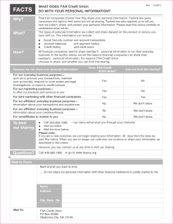


© Copyright 2026