
COVER SHEET
COVER SHEET
This is the author-version of article published as:
McManus, Iain and Clothier, Reece and Walker, Rodney (2005)
Highly Autonomous UAV Mission Planning and Piloting for Civilian
Airspace Operations. In Proceedings Eleventh Australian International
Aerospace Congress, AIAC-11, First Australasian Unmanned Air
Vehicles Conference, Melbourne, Australia.
Copyright 2005 (please consult author)
Accessed from http://eprints.qut.edu.au
AIAC-11 Eleventh Australian International Aerospace Congress
Highly Autonomous UAV Mission Planning and Piloting
for Civilian Airspace Operations
Mr Iain A. McManus, Mr Reece Clothier and Dr Rodney A Walker
Airborne Avionics Research Group, Cooperative Research Centre of Satellite Systems,
Queensland University of Technology, GPO Box 2434, Brisbane, 4001, Australia
Summary: The last decade has seen a rapid increase in the development and deployment of
Unmanned Airborne Vehicles (UAVs). Previous UAVs have been capable of useful missions
with a limited degree of on-board intelligence. However, more on-board intelligence is
required to fully exploit the potential of UAVs. The objective of this research is to increase
the on-board intelligence in two areas: mission planning; and mission piloting. Thereby
improving the integration of a UAV into civilian airspace and reducing operator workload.
This paper presents the research towards the development of the Intelligent Mission Planner
and Pilot. The IMPP enables a UAV to autonomously plan and to perform missions within
civilian airspace. The IMPP employs a novel multidisciplinary approach, exploiting robotics,
3D graphics and computer science techniques. Results are presented based upon testing using
real world data from south-east Queensland. These results demonstrate the performance
achieved by the mission planning and piloting algorithms.
Keywords: UAV mission planning, collision avoidance, high level communications, civilian
airspace, 3D graphics, robotics.
Introduction
In the last decade UAVs have increased in sophistication, advancing from deployments as
target drones for military operations to performing reconnaissance and strike missions in war
zones. UAVs are now routinely deployed for civilian purposes with applications such as
meteorological data collection and farming (eg. Yamaha’s RMAX). However, a limit exists
on how extensively current UAVs can be deployed within civilian airspace. Presently, the
intelligence on-board UAV platforms is low. The consequence of this is that UAVs must be
either deployed within a restricted area or must be continually monitored by trained
personnel. This constrains the deployment of UAV platforms and denies access to the full
capabilities of UAVs.
It is therefore desirable to increase the intelligence on-board UAVs to enable the full
exploitation of their potential. The purpose of increasing the on-board intelligence is to
increase the capabilities of the UAV and to reduce the workload placed upon its human
operators. The research presented in this paper focuses upon the mission planning and piloting
aspects of the on-board intelligence. In this context mission planning refers to the process of
determining the path which the UAV needs to fly in order to meet the mission objectives.
Similarly, mission piloting refers to the processes of collision avoidance and communications
which must be performed during flight. The objectives of the research presented here are:
Eleventh Australian International Aerospace Congress
SundayUnmanned
13 – ThursdayAir
17 March
2005
First Australasian
Vehicles
Conference
Melbourne, Victoria, Australia
1. To perform 3D on-board mission planning for civilian airspace operations.
2. To plan efficient paths in terms of distance travelled, time required or fuel
consumed.
3. To perform collision avoidance in civilian airspace in accordance with the
applicable regulations and with an emphasis on preventing loss of life.
4. To define a vocabulary suitable for communicating with a UAV operating in
civilian airspace and to identify the issues present in using this type of
communications in civilian airspace.
A novel multidisciplinary approach has been adopted to achieve these objectives. This
approach draws upon techniques from the 3D graphics, computer science and robotics fields.
3D graphics techniques have been employed to enable the UAV to construct and maintain its
situational awareness. This situational awareness is used by the UAV to perform high level
tasks such as mission planning and piloting. The mission planning algorithms have been
adapted from techniques used within the robotics field for path planning. The combination of
the 3D graphics and robotics techniques enables the UAV to plan its own missions and to do
so with greater freedom (of movement) than previous approaches. Robotics techniques have
also been used in conjunction with 3D graphics techniques to provide the collision avoidance
capabilities. Finally, computer science techniques have been employed to develop the natural
language based communications algorithms. The advantages of this novel multidisciplinary
approach will be demonstrated using scenarios based upon airspace and terrain data from
south-east Queensland, Australia.
The Autonomous Mission Planning Problem
The mission planning problem is, simply put, that the UAV is given a list of mission
objectives which it must satisfy. To satisfy the objectives (ie. Solve the problem) a plan must
be generated of how to reach the objectives given that there are obstacles which must be
avoided. This section will examine the existing solutions to the problem and identify issues
which prevent these approaches from fully exploiting a UAV’s potential. Based upon the
identified issues a solution will be developed aimed at resolving these issues.
Currently most mission plans for UAVs are prepared by a human operator. This avoids the
need to perform mission planning on-board, but at a cost. The human operator needs to be
aviation trained and the process of planning the mission can take considerable time [1].
Naturally the more complex the mission the longer the time required for mission planning.
There are three main issues with having a human operator performing the mission planning.
Firstly, the UAV is constrained to flying along the path which the operator has planned.
During a mission the UAV cannot change the mission plan, this can only be done by the
human operator. This makes it difficult for the UAV to adapt to changes within the
environment during the mission. Secondly, the workload placed upon the operator is high [1].
This is especially true if the operator is required to replan large sections of the mission during
a flight. Finally, the operator must be aviation trained in order to be capable of planning an
appropriate path. This in turn raises the training and personnel costs for operating the UAV.
The presence of these issues therefore makes the transfer of mission planning to on-board the
UAV a desirable action. By providing the UAV with an on-board planning capacity it can
adapt to changes in the environment. Some UAVs have been developed which can perform
their own mission planning. These systems have however focussed upon military operations
within a war zone. They have therefore placed their emphasis upon factors such as
minimising the size of the target presented to enemy RADARs and other similar military
oriented attributes [2]. These systems, while capable, are not suitable for civilian airspace
applications due to a number of issues.
Firstly, the previous approaches make no accounting for airspace boundaries or issues
associated with them (eg. Being active only in certain hours). Secondly, many of the previous
approaches only consider the planning problem in two dimensions (often a fixed height above
ground is assumed). A two-dimensional approach is not suitable for the civilian airspace
environment where stepped airspace boundaries (ie. A 3D shape) are commonplace. Finally,
the previous approaches typically constrain the UAV to operations along specific paths. This
limits the freedom of the UAV and potentially blocks out more efficient flight paths.
Current on-board UAV mission planning systems are therefore not suitable for operations
within civilian airspace. A mission planning solution is required which addresses these issues.
This paper describes the development of an Intelligent Mission Planner and Pilot (IMPP)
designed specifically to address these issues. In order to provide the necessary mission
planning capability the IMPP needs to:
•
•
•
•
Operate based upon a fully 3D representation of the world
Plan missions on-board the UAV in a manner suitable for civilian airspace
applications
Plan missions that optimise distance travelled, time required or fuel used
Enable the UAV to fly anywhere within civilian airspace that a human pilot
would be permitted to fly
These requirements define the framework for the mission planning research presented in this
section. Consideration is not being given at this stage, of the research, to the sensing side of
the problem. The assumption is made that the information required will be available. The
research focuses upon using and representing the sensory information to assist with mission
planning.
Consideration must also be given to the rules under which the flight will be conducted. The
flight could be conducted under Visual Flight Rules (VFR) conditions, Instrument Flight
Rules (IFR) conditions or a mix of both (ie. VFR during one part of the flight, IFR in
another). VFR conditions impose the least constraints upon the operations of the UAV, which
is one of the research objectives. Furthermore many civilian applications, such as crop
dusting, are conducted under VFR conditions. Therefore the decision was made that the IMPP
would plan missions assuming that the UAV was flying under VFR. This requires the IMPP
to avoid entry into controlled airspace (typically VFR flights are not permitted into controlled
airspace). The UAV must also fly at the appropriate hemispherical altitude based upon its
heading.
In order to satisfy these requirements the IMPP will require a mechanism to store, represent
and interact with information which describes the operating environment. The IMPP will also
require mission planning algorithms which operate based upon the current information stored
about the operating environment.
The proceeding sections will discuss, in detail, the multidisciplinary techniques which have
been implemented in order to create the IMPP. The first aspect of which is the achievement of
on-board situational awareness.
Achieving Situational Awareness
A human pilot operating an aircraft requires a high degree of situational awareness. The
Intelligent Mission Planner and Pilot will also require an awareness of the environment in
which it is operating. The situational awareness will need to contain sufficient information for
the IMPP to plan its assigned mission. The IMPP will need to construct, update and interact
with its awareness of the complex 3D operating environment.
Constructing a dynamic, complex, 3D digital world has historically been restricted to large
dedicated high performance computing systems. However, with the rapid advances in
computing technology, constructing such digital worlds is now possible on, what would be
considered by today’s standards, low-end computers. These advances have made it possible to
construct a digital representation of the civilian airspace environment which incorporates
terrain, airspace boundaries, weather and other aircraft. This digital world is the key to
constructing the situational awareness required by the IMPP to perform on-board mission
planning. As new sensor information is collected the digital world can be updated (eg. Add a
new aircraft) to provide a snapshot of the current environment. The Intelligent Mission
Planner and Pilot then interacts with the digital world. These interactions include determining
if the straight line path between two waypoints intersects with an entity in the world (eg.
Terrain). The interactions with the digital world are performed using techniques established in
the 3D graphics and robotics fields which have been optimised for speed and numerical
efficiency [3].
The first step in constructing this digital world is to identify exactly what the UAV needs to
be aware of. The critical entities which must be represented are:
•
•
•
•
•
•
•
•
Terrain
Airspace boundaries
Adverse weather (eg. storm cells)
Other aircraft
Tall buildings
Navigation aid locations and types
Runways
Radio frequency zones
Other entities could be incorporated if the operational concept requires it, however the above
list was considered to be sufficient to meet the research objectives of this project.
The above entities form an important part of the civilian airspace environment and the UAV
needs to be aware of them. The majority of the entities (terrain, airspace, adverse weather,
other aircraft and buildings) are ones which that a human VFR pilot would be aware of
(through instrumentation, maps etc) and avoid. The other entities are either informational
(navigation aids and radio frequency zones) or are mission start/end points (runways).
A number of sensing capabilities have been assumed for this research. In addition to standard
attitude and position information, the UAV must be aware of the location of other aircraft and
weather (eg. storms). A number of methods exist for obtaining this information, for example
radar-based systems or the Airborne Dependent Surveillance – Broadcast (ADS-B) can
provide the location and speed of nearby aircraft. Similarly, a weather-radar can also provide
location information for adverse weather conditions. However, the focus of this paper is on
how to represent and utilise the information that is assumed to be available. No further
consideration is given as to what sensing capabilities must be implemented in order to provide
this information.
Digital Representation of Airspace Entities
In addition to the location of the entities within the world, their dimensions must also be
known. This means that for each entity within the world there needs to be a description of its
dimensions. This description is necessary for the entities to be ‘drawn’ within the digital
world. The creation (ie. Drawing) of, and interaction with, 3D models is an area which has
been studied in detail within the 3D graphics field for both hardware and software
applications.
The industry standard for rapidly representing 3D models is to use a mesh of triangles
(triangular mesh) [4]. Triangles are a geometrically and mathematically simple shape. They
are constrained within a single plane and are fast to interact with (eg. Detecting if a line
intersects the triangle). Complex objects can be represented using triangular meshes, with the
complexity limited only by the resources available for the storage of the mesh. Fast, efficient
algorithms have been developed for interacting with triangles and by association triangular
meshes [5]. The triangular mesh representation is used by the majority of 3D graphics
hardware and software systems as the standard for rapid modelling of objects.
This approach has been used to model the entities within the digital world. It should be noted
that this is a unique application of 3D computer graphics algorithms to provide situational
awareness for a UAV operating in civilian airspace. Before lower level details of the creation
of the situational awareness are provided a brief explanation of the terminology which will be
used will be provided.
Entity refers to an object from the civilian airspace environment. For example,
terrain, airspace boundaries and other aircraft.
Model is the digital representation of an entity. A model stores both the
properties of the entity (eg. the type [airspace boundary, terrain etc]) and the
shape of the entity.
The shape of an entity is stored (digitally) using a primitive. A primitive is one
of a group of pre-defined shapes which can be used to represent an entity.
Finally, primitives are converted to a triangle mesh to facilitate fast
interactions (eg. detecting if a straight line passes through the model of an
entity) with them.
These terms are shown in the figure below.
Airspace Environment (Real World)
Entity
Type: Airspace Class C
Entity
Type: Terrain
Entities in the Airspace
Environment become Models
in the World Model.
World Model (Digital World)
Model
Type: Airspace Class C
Primitive: Cylinder
Model
Type: Terrain
Primitive: Point Grid
The size and shape of a Model
is specified by its Primitive.
Primitive
Type: Cylinder
Model: Airspace Class C
The Primitive is converted to
Triangle Mesh for collision
detection purposes.
Triangle Mesh
Primitive: Cylinder
Model: Airspace Class C
Fig. 1: World modelling terminology
Every entity is converted to a triangular mesh-based model with which the Intelligent Mission
Planner and Pilot can interact. These interactions include detecting if the straight line path
between two waypoints will collide with an entity and if a location lies within an entity.
This unique approach of using 3D graphics to provide situational awareness for mission
planning in civilian airspace has been successfully implemented into the Intelligent Mission
Planner and Pilot. A 3D digital representation of the airspace environment has been
constructed using information from digital elevation models and airspace charts. The current
digital world stores the terrain and airspace details for a section of the eastern coast of
Australia. This section covers a region measuring 270 nm (east-west) by 240 nm (north-south)
and contains over 70 airspace boundaries.
By continually updating the digital world based upon current sensor data the IMPP, and other
UAV systems, can be provided a with high-degree of situational awareness. This situational
awareness provides the foundation for the mission planning and piloting algorithms within the
IMPP.
Autonomous Mission Planning
Once the digital representation of the world (ie. The situational awareness) has been created,
high level activities such as mission planning and piloting can be performed. The autonomous
mission planning algorithms are the core component of the Intelligent Mission Planner and
Pilot (IMPP). These algorithms use both the mission objectives provided by a human operator
and the on-board situational awareness to plan the mission. The planning process involves
determining an efficient and collision free flight path which will achieve the assigned mission
objectives. The output of the planning process is a series of waypoints (ie. Flight path) which
the UAV must fly to (in sequence) in order to achieve the mission objectives.
The field of mission planning has been studied in depth by the robotics industry [6, 7].
Research to date can be divided into two categories: solutions where all information is known
a priori; and solutions where either partial or no information is known a priori. Information in
this case refers to the layout of the world and the locations and dimensions of entities within
the world. Solutions which initially have a full awareness of the operating environment (ie.
All information provided a priori) can develop a complete plan from the start to the end of the
mission. These plans are known as ‘global plans’. As global plans cover the entire mission
they can be made efficient over the entire course of the mission (ie. Globally efficient).
The disadvantage of developing global plans is that the mission planner requires a large
amount of a priori information in order to develop the plan. The alternative approach is to
plan for the near future (eg. 10 minutes). This uses only a partial awareness of the
environment and requires less information. Solutions of this type can only develop plans for
the immediate future (ie. Plan for 10 minutes into the future). These plans are known as ‘local
plans’. Local plans have the disadvantage that they may not be capable of achieving the
required goal as they can become lost or stuck due to their limited view of the world. Finally,
as local plans cannot consider the entire mission at once they are not guaranteed to produce
plans which are efficient over the entire course of the mission. Efficient local plans can only
be developed for the immediate future, known as ‘locally efficient’.
For UAV mission planning it is possible to provide sufficient information a priori to enable
the UAV to develop global plans. This information would include as a minimum the terrain
and airspace boundary information. Short-term disturbances (eg. Avoiding a collision with
another aircraft) can be accommodated through reflex-style algorithms that make local
changes to the global mission plan. This mixed approach of global planning algorithms and
reflexes will enable the IMPP to plan efficient paths within civilian airspace. The reflex-based
collision avoidance algorithms are presented later in the paper.
A range of methods, for global planning in known environments, have been developed and
proven by researchers in the robotics field. These methods range from algorithms which
partition the world into grids then move from cell to cell, to artificial intelligence based path
searches. The most common methods available are:
•
•
•
Cube space (C-Space) algorithms where the digital world is divided into cubes
[8]. These are a 3D extension of 2D grid worlds.
Octree algorithms, which are a hierarchical representation of C-Space which
enables the digital world to be viewed at multiple resolutions [7].
Voronoi diagrams, which compute a graph of the free paths within the digital
world [9].
Voronoi diagrams have previously been employed for UAV mission planning. They are
typically combined with artificial intelligence based graph search algorithms [9].
Voronoi diagrams can be used to incorporate the concept of risk into the mission planning
process by keeping further away from dangerous obstacles (eg. A military test range). The
primary disadvantage with Voronoi diagrams is that the UAV is required to fly along the lines
of the Voronoi graph (except when transiting to/from a waypoint). This prevents the UAV
from flying close to obstacles and thus eliminates potentially more efficient plans. Previous
UAV implementations [9] have only used Voronoi diagrams for two-dimensional mission
planning. However the civilian airspace environment is three-dimensional and therefore
demands a three-dimensional planning approach in order to provide a wider operating
envelope.
Cube-Space Mission Planning
Cube-Space (C-Space) algorithms have been employed frequently within the robotics field to
solve the mission planning problem [10]. To date C-Space algorithms have not been applied
for UAV mission planning. The C-Space algorithms are based upon dividing the 3D world
into cubes. The cubes are marked as either free or occupied. A cube which contains any part
of an entity within the world (eg. A region of airspace) will be marked as occupied. As can be
seen in the diagram below all cubes (in this case squares since it is a plan view) that overlap
with the region of airspace are marked as occupied (shaded).
Real World
C-Space Representation
Fig. 2: Plan view comparison of real world and C-Space representations
Additionally each free cube is assigned a value, for example the distance from the cube to the
goal (destination). The path (ie. Mission) is planned by jumping from cube to cube with the
direction of the jump based upon the values assigned to the free cubes. This process is shown
in the diagram below.
Mission planner scans all cubes adjacent to the
current (shaded) cube. Typically the planner will
need to examine all 26 adjacent cubes. However,
when the current cube is against the side of the
virtual world less cubes will need to be
considered.
Up (Z)
North (X)
4
3
5
2
4
5
3
5
4
East (Y)
6
The mission planner locates the cube with the
smallest value (shown in black) and then moves
to that cube. This represents the path of greatest
gradient. The process is repeated until the goal is
reached.
6
6
6
7
6
6
8
4
5
6
8
9
5
5
6
6
7
Fig. 3: Example of the scanning process performed by the mission planner
The critical part of C-Space based mission planning is the algorithm used to map values onto
the free cubes. One commonly used mapping is to propagate a 3D wave from the goal
(destination) marking each free cube with the distance to the goal [6, 7]. This can be viewed
as a sphere expanding from the goal where the edge of the sphere is the wavefront being
propagated. It is important to note that this is not the straight line distance from the cube to
the goal. Instead it is the distance that the UAV would need to fly to reach the goal. This
requires that the distance wave refract around obstacles so that each cube is accurately marked
with the distance required to move from that cube to the goal. The mission planner then starts
at the UAV’s current location and scans the adjacent cubes. This process is shown in plan
view in the figure below.
5
4
3
2
Start
1
Destination
5.4
1
Obstacle
6.4
Mission plan
7.4
8.4
9.4
9.8
15.2
10.8
11.8
12.8
13.8
14.8
Fig. 4: Path planning process
After scanning the adjacent cubes the mission planner then moves to the cube closest to the
goal. This approach is repeated until the goal is reached.
The distance wave mapping has been successfully employed in the past for autonomous
ground vehicles [7]. However the disadvantage of the distance wave is that it does not factor
in the time taken or energy (eg. Fuel) used to traverse the path. For example there is a
significant difference between an aircraft flying a 50nm path at a constant altitude and flying a
80 nm path that requires the aircraft to climb and descend thousands of feet to avoid airspace
boundaries. As part of the research two additional mappings have been developed to enable
the generation of mission plans which are more consistent with the practices of a human pilot.
The first mapping estimates the effort, in terms of time, to fly to the goal. The effort wave
mapping is applied by first applying the distance wave. Then, based upon the capabilities of
the aircraft, the time to fly from each free cube to the goal is estimated. This is calculated by
assuming different speeds based upon the direction in which the UAV would fly. The speeds
were determined based upon simulated testing which examined the speed of the aircraft in
different configurations (climb, descent etc). The diagram below shows the speeds used to
determine the time to fly to each cube within the world.
80
80
80
80
1
80
120
Climb
80
80
120
120
80
120
1
120
120
120
Straight and level
120
Up (Z)
North (X)
160
160
160
1
160
160
Descend
East (Y)
160
160
160
Fig. 5: Speeds (in knots) used for effort wave calculation. (Current cube is shaded)
The result of this mapping is that the decision between climbing, descending or making no
altitude change is weighted appropriately. Very high penalties are assigned to pure vertical
manoeuvres in order to prevent the path planner from choosing such a path. Ascending incurs
a penalty in terms of speed, whereas descending incurs an advantage. The consequence of this
mapping is that the UAV will fly the path of approximately shortest time. The UAV
prioritises flying straight and level over ascending. Although an advantage is given to descent
manoeuvres, the UAV will not descend to the lowest level possible and then ascend at the last
minute. This is prevented by the penalty for ascending, which makes such a mission plan too
costly. Determining the path with the effort wave mapping is identical to that for the distance
wave mapping. The new mission plan is generated by following the path of greatest gradient.
The final mapping estimates energy required to manoeuvre the aircraft in terms of the fuel
used. Unlike the effort wave, the fuel wave mapping does not build on top of the distance
wave. The fuel wave factors in both the distance and the time to move that distance when the
wave is propagated. The equation used to determine the fuel usage was based upon the engine
model provided by the AeroSim Blockset [11]. First, a basic aircraft model is used to estimate
the time the UAV would require to fly from one cube to another. This information is then
used by the engine model to estimate the fuel which would be consumed in performing the
manoeuvre. Consequently, the UAV will attempt to fly the most fuel efficient path. The
method for generating the mission plan using the fuel wave mapping is identical to that for the
distance and effort waves. Any of these mappings could be used to perform on-board mission
planning by the IMPP. The performance of the different mappings will be compared further
on in this paper.
Octree-based Mission Planning
The second type of mission planning method available is the Octree, which is an extension to
the C-Space methods. Octrees are a hierarchical structure that represent the world at multiple
resolutions [7]. The multiple resolutions make crossing large empty spaces more efficient
than for a C-Space representation. Rather than moving from cube to cube, multiple cubes can
be crossed at the same time. This is shown in the figure below.
Destination
Start
Obstacle
Mission plan
C-Space mission plan requires 19 jumps
Octree mission plan requires 12 jumps
Fig. 6: Efficiency differences between C-Space and Octree representations
While this greater efficiency is beneficial, Octrees posses two major disadvantages. Firstly,
they consume a larger amount of memory than C-Space methods. For example, consider the
situation where a cube, with a side length of 16 nautical miles, is represented at a resolution of
1 nm. The C-Space representation will require 16x16x16 = 4096 data structures to represent
it. An Octree representation would require 16x16x16 + 8x8x8 + 4x4x4 + 2x2x2 + 1x1x1 =
4681 data structures. This is a 14% increase in the storage requirement and as the dimensions
increase (or the resolution decreases) this overhead will grow.
Secondly, the path planning process is made slower due to the greater overhead in traversing
the Octree structure. This overhead results from the process of relocating to parent, child or
adjacent nodes. This is slower than for C-Space which can be represented as a multidimensional array.
In the Octree method the blocks (called nodes) are marked as either fully-free, fully-occupied
or partially-occupied. If a node is partially-occupied, by an entity, then it is possible to change
to a finer resolution version of the node and then locate the free nodes within it. The mappings
described for C-Space can also be applied for Octrees in the same manner. The path planning
algorithms are also identical. The only change is that the planner can move to a partiallyoccupied node as well as a fully-free node. The Octree algorithms can provide more efficient
planning, however the greater overheads frequently outweigh the performance gains, as will
be shown in the results.
The C-Space and Octree algorithms mentioned in this section were implemented into the
Intelligent Mission Planner and Pilot (IMPP). Both types of algorithms are capable of meeting
the research objectives. The Voronoi diagram methods have not been adopted as they greatly
restrict the freedom of the mission planner by forcing flights along pre-defined paths. The
outlined methods enable the IMPP to perform global mission planning on-board the UAV for
civilian airspace applications. Results of testing conducted on the planning algorithms will be
presented later in the paper.
Collision Avoidance in Civilian Airspace
Collision avoidance is an essential area to address for a civilian airspace integrated UAV. Any
aircraft operating in civilian airspace in the presence of other air traffic will require a collision
avoidance capability. This section discusses the development of a collision avoidance
capability for a UAV operating in civilian airspace based upon a unique fusion of 3D
computer graphics and robotics techniques.
Collision avoidance is a two step procedure comprising of both collision detection and
collision resolution. Collision detection is the process of detecting if a collision may occur.
The development of a strategy to then prevent the detected collision from occurring is known
as collision resolution. These two stages of collision avoidance will be dealt with separately.
Consideration will first be given to the collision detection stage.
Collision Detection
Collision detection involves detecting if a collision may occur. In order to perform this
detection it is necessary to be aware of the current location of the UAV and the locations of
the entities in the world which must be avoided. For the purposes of this research it will be
assumed that this information will be available through the on-board situational awareness
created through the 3D graphics algorithms This section will focus upon the algorithms which
utilise this information to determine if a collision scenario is present.
Before specific algorithms can be discussed it is necessary to identify what entities must be
avoided as well as other constraints (eg. regulations) related to collision detection. The
situational awareness, described earlier, is capable of storing details for the following types of
entities.
•
•
•
•
•
•
•
•
Terrain
Airspace boundaries
Adverse weather (storms and clouds)
Other aircraft
Navigation aids
Runways
Buildings
Radio frequency zones
Of the entities listed there is clearly no need to avoid radio frequency zones, navigation aids
or runways. The remaining entities (terrain, airspace boundaries, adverse weather, other
aircraft and buildings) must be avoided. These are all entities which an aircraft operating in
civilian airspace may encounter and which a human pilot would avoid. It is important to note
that other aircraft and buildings will be deemed inhabited by the collision avoidance
algorithms.
One of the key constraints upon the UAV is to prevent injury or loss of life to the fullest
extent possible. To this end the UAV needs the capability to differentiate between inhabited
and uninhabited entities to enable it to place greater emphasis on avoiding inhabited entities.
The collision detection algorithms must therefore possess the means to make this
differentiation. Finally, the collision detection procedure should be performed in accordance
with the Civil Aviation Regulations. These regulations state that an aircraft is not required to
perform avoidance manoeuvres when it is being overtaken. The criteria for if an aircraft is
being overtaken is shown in the figure below.
Not being overtaken
Not being overtaken
70°
Being overtaken
70°
Being overtaken
Fig. 7: Criteria for if an aircraft is being overtaken
As shown in this diagram if the other aircraft is in a region 70° either side of the tail of the
aircraft then it is considered to be overtaking. There is no requirement to consider an
overtaking aircraft for collision avoidance purposes. In this scenario the regulations permit the
pilot discretion to determine if collision avoidance manoeuvres must be performed. For a
UAV in the same situation the question is: how should the UAV decide what to do? It has
been assumed that the UAV will have a full awareness of the location of the overtaking
aircraft (intruder). Therefore the UAV will be able to calculate the distance between it and the
intruder. This distance can be used to decide if collision avoidance manoeuvres are required.
Beyond a set threshold there will be no reaction to the intruder. However, once within the
distance threshold collision avoidance procedures will be enacted. The determination of this
threshold will be discussed in the proceeding section.
Developing an Approach to Collision Detection
A significant body of research exists in the robotics field in the area of collision avoidance.
The leading approach in this field is potential field theory. Potential field theory has been used
on-board UAVs previously for collision avoidance purposes [12]. However, these
applications have not considered operations in civilian airspace and the ensuing issues (eg.
regulatory constraints) that result from operations in civilian airspace. There is therefore a
need to extend this approach to encompass the additional issues which civilian airspace
presents.
Firstly a brief overview of potential field theory will be provided. Essentially potential field
theory operates by assigning a repulsive field to the entities which are to be avoided. This
repulsive field exerts a force upon the UAV which ‘pushes’ the UAV away from the entity.
The strength of the force is determined by the potential field magnitude (ie. How hard the
field can push) and the distance from the entity. As the UAV gets closer to the entity the
strength of the force exerted upon the UAV increases. Potential fields also posses shape and a
zone of influence. Shape refers to the shape of the potential field being generated (eg.
spherical etc). The zone of influence is the distance beyond which the potential field strength
is zero (ie. Has no effect). The zone of influence is used to reduce computational complexity.
The first step in using potential field theory to perform collision detection is to establish
where the entities in the world are in relation to the UAV. The on-board situational awareness
tracks the locations of all of the entities of which the UAV is aware. In addition to the
location information the situational awareness can also identify the specific type of an entity
(eg. building, other aircraft etc). The type information can be used to define the magnitude of
the potential field which each entity generates. This is necessary in order for the UAV to
place a greater emphasis on avoiding collisions with inhabited entities over uninhabited
entities. Based upon this, priorities can be defined using the guidelines below.
•
•
•
•
At the highest level are the inhabited entities (ie. Other aircraft and buildings). As
these entities are inhabited the UAV must place the highest priority on avoiding these
entities over all others.
At the next level are the entities which are uninhabited but which will cause
substantial damage to the UAV. This category includes only terrain.
The next level includes entities which have the potential to cause damage to the UAV.
Adverse weather conditions fall under this category.
At the lowest level are entities which will not cause damage to the UAV. This includes
airspace boundaries.
These guidelines can then be used when defining the magnitude of the potential fields which
each entity will generate. By following these guidelines the constraint of emphasising
preventing loss of life or injury can be adhered to. It is important to note that the formalisation
of guidelines of this nature has not previously been performed for UAV collision avoidance
using potential field theory. In order to define the magnitudes the guidelines must be used in
conjunction with simulated flights. The simulated flights expose the collision avoidance
algorithms to a range of collision scenarios which enables the potential field magnitudes to be
tuned. The tuning is performed until the UAV maintains a minimum threshold from the other
entities for each of the testing scenarios. For the purposes of this research the safety threshold
has been set at 10 seconds for a head on, aircraft-on-aircraft collision.
In addition to the magnitude of the potential fields it is necessary to also consider both the
shape and the zone of influence. The situational awareness stores the shape information for all
entities which are detected. This information can therefore be requested from the situational
awareness and used to accurately model the potential fields of the entities.
The zone of influence determines at what distance the potential field generated by an entity
begins to effect the UAV. Increasing the potential field results in the UAV performing
avoidance manoeuvres sooner than if the zone of influence was smaller. It is desirable for the
zones of influence of large entities to extend further than for smaller entities. A larger zone of
influence enables the UAV to make a more gradual (and shorter) avoidance manoeuvre
around the entity. Entities such as other aircraft, which are small, do not require as large a
zone of influence as a large airspace boundary. As the situational awareness stores the shape
of every entity it is possible to use this information to describe how ‘large’ an entity is.
This section has, up to this point, detailed how the potential field can be defined for all of the
entities which must be avoided by the UAV. The final aspect to consider is the process of
combining this information into a usable form. This requires the determination and
combination of the potential field forces exerted upon the UAV by all of the entities in the
airspace environment. This process requires firstly that the potential field force from each
entity be determined. This force possesses both a direction (which points away from the
entity) and a magnitude (which indicates how strongly the UAV is being pushed away). The
magnitude of the potential field force is calculated using the field equations below:
F =
PFS
D
F =0
for D ≤ Z I
for D > Z I
(1)
In the equation above |F| is the magnitude of the potential field force. PFS is the strength of
the potential field (which is assigned based upon type). D is the distance between the entity
and the UAV. ZI is the zone of influence. The direction of the potential field is calculated as
the normal (pointing outward) from the surface of the entity at the point closest to the UAV.
Combined with the magnitude this gives the potential field force exerted upon the UAV by
that entity.
The final task is to combine the potential field forces of the individual entities. The
combination of the forces yields a single force vector which indicates the direction furthest
away from the entities. This vector is calculated as the summation of the individual potential
field force vectors from each entity (except those where the UAV is outside of the zone of
influence).
The combined force vector provides a distilled representation of the collision scenario which
is present. The force vector indicates how close the UAV is to a collision (by its magnitude)
and also indicates the most direct path away from the collision. Although the potential fields
have been combined into a single vector, this does still factor in specific issues such as
prioritising avoiding inhabited entities. An inhabited entity will generate a stronger field than
an uninhabited entity. Therefore the stronger potential field of the inhabited entity will be the
dominant component of the combined force vector. This will in turn lead to the UAV placing
a greater emphasis upon avoiding the inhabited entity. e combined force vector is then the
input to the collision resolution algorithms.
Collision Resolution
The combined force vector provides the basic information required to determine the
appropriate collision avoidance manoeuvre to perform. The magnitude of the force provides
an indication of how near the UAV is to a collision. The higher the magnitude the closer the
UAV is to a collision. The magnitude therefore also indicates the severity of the avoidance
manoeuvres which the UAV must perform. The direction information from the force vector
indicates the most direct path away from the collision scenario.
However, the UAV cannot necessarily fly the most direct path. The Civil Aviation
Regulations define specific procedures which must be followed when avoiding a collision
with another aircraft. The established convention is that aircraft in a head on collision
scenario turn right to avoid the collision. A right hand turn may not necessarily be the most
direct path away from the collision. However, as it is a legal requirement placed upon aircraft
operating in civilian airspace the UAV will need to adhere to this. The collision avoidance
system must therefore take this into account. It is important to note that this regulation only
applies to aircraft which are flying in opposite directions (ie. One aircraft is not overtaking the
other). For the situation of avoiding an aircraft which is closing in from the overtaking
position the UAV is not limited in which direction it will take to avoid the collision.
Therefore the UAV can take a more direct path away from the collision. The diagram below
represents how the UAV will react, in terms of heading changes, for different collision
scenarios.
Collision vector is forward
and left of the UAV.
Collision vector is forward
and right of the UAV.
Resolution: Right turn
Resolution: Hard right turn.
Collision vector is rearward
and left of the UAV.
Collision vector is rearward
and right of the UAV.
Resolution: Right turn
Resolution: Left turn
Fig. 8: Heading manoeuvres for collision resolution
Based upon the simulated testing which was conducted the following numerical values were
assigned to the different types of turns which the UAV can perform to avoid a collision.
•
•
•
Right turn – deflect current heading by 45°
Hard right turn – deflect current heading by 135°
Left turn – deflect current heading by -45°
The end result of employing this form of collision avoidance strategy is that the UAV will, in
accordance with regulations, deflect its path to the right when faced with an oncoming
aircraft. In the case of an overtaking aircraft, the UAV will manoeuvre out of the path of the
overtaking aircraft in the most direct manner possible.
This far the discussion has focussed solely upon horizontal manoeuvres in response to a
collision scenario. However, there is no reason to limit the UAV to only horizontal responses.
The combined force vector provides sufficient information to also make a vertical manoeuvre
in response to a collision scenario. The vertical (Z axis) component of the force vector
indicates the location of the collision in the vertical axis in relation to the UAV (ie. Is the
collision above or below the current UAV altitude?).
The magnitude of the force in the Z axis and the direction (up or down) therefore indicates
whether the UAV should climb or descend and by how much. The equation below was
determined empirically through simulations of various collision scenarios.
( )
∆A = 2 | F | ×sign F Z
(2)
In this equation the altitude deviation (? A) is calculated as double the combined force
magnitude (|F|). The sign of the altitude deviation is determined based upon the Z component
of the combined force (FZ). This equation will cause the UAV to climb or descend in order to
move further away from the potential collision. The amount of altitude change executed will
be proportional to the magnitude of the combined potential field force.
The combination of the altitude and heading avoidance manoeuvres affords the UAV a range
of options for the avoidance of a collision. The novel approach which has been outlined
enables the UAV to avoid a collision while also adhering to the applicable Civil Aviation
Regulations. Testing results will be presented later in the paper. The next section presents the
research conducted into the development of the on-board communications capability.
Natural Language Communications in Civilian Airspace
The final aspect to consider is the area of communications. Any aircraft operating in civilian
airspace must communicate with a wide range of entities (eg. Air Traffic Control). Currently
deployed UAVs rely upon a human operator to perform the communications required by the
UAV. The human operator communicates either directly (to ATC etc) or alternatively the
communications are relayed via the UAV. This places an additional burden upon the human
operator who must act as a ‘go-between’ between the UAV and others.
It is therefore desirable to imbue the UAV with sufficient on-board intelligence in order for it
to perform the required communications itself. This will facilitate a reduction in the operator
workload and provide an increased capability for the UAV to integrate into civilian airspace.
This section describes the development of a novel solution to the on-board communications
problem based upon computing science techniques.
Overview of the Communications Problem
There are two main types of approaches to the problem of performing these communications.
The first category of approaches use a proprietary digital transmission. Communications of
this nature can be performed on-board the UAV without the need for human operator input.
However, this type of communications mechanism can only be used to communicate with the
UAV’s operators. For ATC and others to communicate with the UAV they would require
specific hardware. The adoption of a proprietary digital communications mechanism for
civilian airspace UAV communications is therefore undesirable due to the large infrastructure
changes which it would require.
The second category of approaches use an open communications standard, that is natural
language (either spoken or written). This enables the UAV to communicate with a wide range
of entities without the need for substantial infrastructure changes. An open communications
standard is therefore preferable for a civilian airspace integrated UAV. Highly capable open
communications approaches have been developed for both spoken and written natural
language.
UAVs such as the Global Hawk perform their communications using spoken language [13].
However, the generation and interpretation of this speech is not performed by the on-board
systems of the Global Hawk. Instead the Global Hawk acts as a relay to one of its human
operators. The human operator communicates (via the Global Hawk) with Air Traffic Control
(and others) and then issues updates to the Global Hawk. This provides the Global Hawk with
the capability to communicate in the same manner as any other aircraft operating in civilian
airspace. However, it places a higher burden upon the UAV’s human operators especially
during operations in congested airspace. Furthermore if the communications between the
human operator and the UAV are blocked (intentionally or unintentionally) the UAV loses its
ability to communicate. It is therefore undesirable for a civilian airspace integrated UAV to
use a communications approach that is reliant upon a human operator.
However, written natural language based approaches have been developed which operate
without the need of a human operator. The leading example of this is the natural language
communications system developed by MIT [14, 15]. This approach by MIT enables a UAV to
perform its own communications through a text based natural language interface. MIT have
developed and applied these techniques to a UAV targeted towards defence applications.
There are however issues which the MIT approach has not considered.
Firstly, the MIT approach has not given consideration to operations in civilian airspace. A
UAV operating in civilian airspace will typically be in communication with a more diverse
range of entities than a defence oriented UAV. Secondly, MIT have focussed solely upon
using the natural language communications for issuing commands to the UAV. However, a
UAV operating in civilian airspace can also use natural language to gain a heightened
situational awareness of the operating environment.
This chapter will present a novel natural language based approach which addresses these
issues. This approach will extend the previous approaches to provide support for civilian
airspace applications. The new approach will enable a UAV to be issued both commands and
updated situational awareness information. Finally this approach will cater for the differing
communications from ATC, FIS, the UAV’s operators and other aircraft. The novel aspects of
this research are:
•
•
•
Evaluation of natural language for civilian applications
Adoption of natural language for situational awareness purposes in addition to
mission planning
Identification of a vocabulary suitable for communications with a wide range
of entities of varying skill levels.
The proceeding section will discuss the details of the development of this new approach.
An Approach to On-board Communications
Communications to and from an aircraft during flight occur for a specific purpose. Identifying
these purposes is an important first step in the development of a natural language based
communications system as they provide a framework of the functionality which must be
provided. A UAV operating in civilian airspace may be communicated with (or may
communicate) for the following reasons.
•
Communications to the UAV
o From the UAV’s operators
§ Updating mission plan
§ Updating situational awareness
o From Air Traffic Control
§ Updating mission plan (eg. ordering a hold)
§ Updating situational awareness
o From Flight Information Services
§ Updating situational awareness
o From other aircraft
•
§ Updating situational awareness
Communications from the UAV
o To the UAV’s operators
§ Advising of current status
o To Air Traffic Control
§ Advising of current status
§ Requesting access to controlled airspace
o To Flight Information Services
§ Advising of current status
o To other aircraft
§ Advising of current status
For the purposes of this research consideration will only be given to the communications to
the UAV. Communications from the UAV to others are beyond the scope of the research and
will not be considered.
As can be seen from the list above the communications, although from a wide range of
sources, fall into two basic categories. The first category encompasses all communications
which are to enact changes in the mission plan. These changes could be to provide the UAV
with a completely new mission plan or to request the UAV to perform a specific manoeuvre
(eg. hold at a given location). The second category of communications includes all those
which provide updated situational awareness to the UAV. For example the UAV could
‘listen’ to weather broadcasts and use this information to update the situational awareness
which it is maintaining. Information may also come in which describes the intended flight
path of other aircraft.
Based upon these categories the natural language communications system must provide the
following functionality.
•
•
•
Receive an updated mission plan (completely new or modified)
Receive a manoeuvre command to be executed immediately (eg. hold at
location)
Receive updated situational awareness information (eg. location of adverse
weather system)
These functional requirements provide the framework for the development of the natural
language based communications system. They define the capabilities which must be provided.
The next step in the development of the natural language based communications system is to
define the vocabulary for the communications.
Civilian Airspace Vocabulary
An important component of using natural language for communications with the UAV is the
vocabulary supported by the communications. The vocabulary in this context refers to the
way in which commands and information updates are phrased. To date there has been no
analysis of what vocabulary is appropriate for a UAV operating in civilian airspace. The
vocabulary defines what terms the UAV will be capable of understanding and what meanings
the UAV will assign to each term. When defining the vocabulary there are two main issues to
consider: who will be talking to the UAV? And what applications will the UAV be being
applied to. This section will answer these questions and in so doing define a suitable
vocabulary for civilian airspace communications.
In the case of the first question the UAV will be talked to by its operators (which may have
limited training in the case of commercially sold UAVs), Air Traffic Control, Flight
Information Services and potentially other aircraft. This presents a substantial challenge from
a communications perspective as the UAV will be receiving communications from a wide
range of sources with varying skill levels. The operator of the UAV may not be aviation
trained as the intent with this research is to reduce the need for highly trained operators.
Therefore it cannot simply be assumed that using the standard civil aviation radio calls will be
suitable. Furthermore the established radio calls are not designed for the simple commanding
of common applications performed by civilian aircraft (eg. crop dusting). The vocabulary for
the communications must therefore take this into account. A trade-off will be required
between the need for a simple communications mechanism and the adherence to established
radio procedures.
With respect to the second question the UAV will be applied to tasks common in the civilian
airspace environment. For the purposes of this research a number of common tasks were
selected as test cases. The chosen tasks were: crop dusting, skywriting and executing different
holding patterns. These tasks were chosen as they are common in the civilian airspace
environment and represent a diverse range of operational requirements. The communications
vocabulary will need to cater for these tasks and reduce workload required by the operator to
command the UAV to perform these tasks.
Based upon these considerations the vocabulary must both cater for a diverse range of skill
levels in addition to a diverse range of tasks. The next step prior to defining the specific
vocabulary for the communications is to consider the information which must be conveyed
through the communications. In order to identify this information a number of examples of
communications which the UAV may receive will be provided. The examples below have
been defined based upon the tasks to which the UAV may be applied as well as other
commands and information which may need to be communicated to the UAV.
•
•
•
General Commands
o Hold at location, altitude on heading
o Circle at location at altitude and turn direction
Task Commands
o Skywrite message at altitude and location
o Fly a grid pattern over location at resolution
Situational Awareness Updates
o Incoming aircraft currently at a location 1 travelling to location 2 at
altitude and airspeed
o Adverse weather system detected at location with severity
Considering these examples there are a number of elements common amongst the different
commands and information updates. For all communications there are three key elements: the
task to perform; the location to perform the task; and, extra parameters which define how to
perform the task. In other words the communications all indicate what (ie. The task or
information being updated), where (ie. Location to perform the task) and how (ie. Parameters
for the performance of a task). Each of these elements (what, where and how) will be
considered in turn and the vocabulary for each established.
The ‘What’ Element
Considering first the describing of what the UAV is required to do or what information is
being updated. As previously stated the vocabulary used must be readily understandable
across a range of skill levels. In order to make the communications more accessible the
decision was made to adopt a very simple and descriptive vocabulary for the commands but
one which remains comprehendible to aviation trained personnel. The list below shows
common commands and information updates which the UAV may receive and the
corresponding descriptive vocabulary. It is important to note that this is not an exhaustive list.
It is a small subset of the range of commands which could be implemented. This reduced list
provides a broad representative sample of communications which the UAV may receive.
•
•
Commands
o Takeoff from a specific location
§ Vocabulary: Takeoff
o Fly to a specific location
§ Vocabulary: Fly to
o Land at a specific location
§ Vocabulary: Land at
o Circle a given location
§ Vocabulary: Circle
o Execute a grid search (ie. Fly a grid pattern)
§ Vocabulary: Execute a grid search
o Hold at a specific location
§ Vocabulary: Hold at
o Fly a figure eight pattern
§ Vocabulary: Perform figure eight
o Skywrite a specific message
§ Vocabulary: Skywrite
Information Updates
o Aircraft movement update
§ Vocabulary: Traffic
o Adverse weather detected
§ Vocabulary: Be advised of
The vocabulary which has been identified for each of these communications is clear and
unambiguous, both of which are important attributes for an on-board communications system.
Furthermore, the clarity of the vocabulary enables it to be comprehended by persons with a
range of different skill levels.
The ‘Where’ Element
The second element of the vocabulary to consider is the ‘where’ element. This defines either
where an action is to be performed or where in the world the information update refers to.
Traditionally when working with a UAV locations would be specified as a latitude, longitude
and altitude. This approach is precise and is perfectly valid. However, it is not intuitive and it
is not how locations are typically described for civilian airspace operations. For operations in
civilian airspace it is more common to specific a location in terms of its name (eg. Brisbane
airport) or its displacement relative to a known location (eg. 50 nautical miles south west of
Caboolture). Location’s specified by Air Traffic Control will be given using one of these
manners. Therefore, the vocabulary must take this into account and must accommodate for
the varied manner in which location information (ie. The ‘where’ element) may be
communicated to the UAV.
Essentially there are two ways (excluding specifying latitude, longitude and altitude) in which
the location information can be specified: absolute or relative. Specifying an absolute location
means that the UAV is told the name of where it is to perform the task or where in the world
the information update refers to. A relative location is comprised of both an absolute location
(known as the reference) and a displacement relative to that location (known as the offset).
Absolute locations can be readily accommodated through the usage of a location database.
This database would store the names of various locations and their corresponding coordinates
(ie. Latitude, longitude and altitude).
The list of locations would need to contain all those which the UAV may need during its
mission. In order to define the contents of this list it is necessary to consider what locations a
human pilot would need to be aware of during flight. For a human pilot the locations which
they will fly with reference to will be a mix of established navigational points (eg.
navigational beacons and airports) and custom locations (eg. a specific mountain). A UAV
will therefore be required to possess a similar level of knowledge. There are freely available
databases of all of the navigation aids existing within the world. These lists define the name,
type and location of the navigation aid. These lists can in turn be used to populate the location
database which the UAV will use in determining where a specific named location is. Custom
locations such as mountains or the surveyed coordinates of a farmer’s crops can be added to
the database dependent on the specific mission. When presented with a named location the
UAV will then search the database to determine the latitude, longitude and altitude of the
given location.
This location database can be used in part to process any relative locations which the UAV is
given. The UAV will use the location database to determine the latitude, longitude and
altitude of the reference point. After this the offset information must be interpreted in order to
determine the specific location which the UAV has been given. The offsets in this case will be
given in the form of “[distance] [direction] of …”. For example, “[50 miles] [south west] of
…”. Considering the distance first, dependent upon who the communications have come from
(ATC, human operator etc) the distance may be specified in different units. It is prudent
therefore for the UAV to comprehend distances specified in the common units of nautical
miles, miles and kilometres. There is no need for smaller units as it is unrealistic that the
UAV would be asked, for example, to fly to 300 metres south of Brisbane. The final
component of the offset is the direction. These directions are commonly specified using the
terminology north, south, north east etc. The UAV will, in turn, be required to comprehend
the common direction terms. The directions which the UAV will need to understand are
shown in the figure below.
This section has defined how location information (ie. The ‘where’ element) can be
communicated to the UAV in a manner which is both simplistic and consistent with
established procedures.
The ‘How’ Element
The final element to consider is the ‘how’ element. This describes the manner in which the
UAV is to execute the given or command or provides additional details for the information
update. The list below shows the communications which are being used as the demonstrate
set. For each of the communications the ‘how’ information is identified.
•
•
Commands
o Takeoff from a specific location
§ How Information: None
o Fly to a specific location
§ How Information: Altitude
o Land at a specific location
§ How Information: None
o Circle a given location
§ How Information: Altitude, direction, circle radius and
number of circuits
o Execute a grid search (ie. Fly a grid pattern)
§ How Information: Altitude, resolution, length and width of
search area
o Hold at a specific location
§ How Information: Altitude and heading
o Fly a figure eight pattern
§ How Information: Direction (of first loop), altitude, radius
and heading
o Skywrite a specific message
§ How Information: Message, altitude and font
Information Updates
o Aircraft movement update
§ How Information: Aircraft ID, altitude and speed
o Adverse weather detected
§ How Information: Type, severity and altitude
The ‘how’ information which will be included in the majority of communications contains a
number of common elements. These common elements are:
•
•
•
•
Distance (altitude, resolution, radius and area dimensions)
Direction (eg. clockwise)
General numerical information (number of circuits and heading)
General information (message to skywrite, aircraft ID and weather details)
It is necessary therefore to consider the vocabulary which will be used to communicate these
elements to the UAV. In the case of distances the same vocabulary used for specifying
relative location can be applied for consistency. The distances will therefore be comprised of
both a numerical value and then the units for the numerical value. For example, distances can
be given as ’50 nautical miles’. However, in this case additional units will need to be
supported dependent upon the parameter. For example altitudes are typically given in feet or
flight levels (for altitudes above 11, 000 feet). The units which will need to be supported are
listed below based upon the type of parameter.
•
•
Altitude
o Units: Metres, feet and flight level
Resolution, radius and area dimensions
o Units: Kilometres, miles and nautical miles
The remaining elements (direction, general numerical and general information) require the
specification of only a single parameter (eg. a heading) rather than the two parameters (value
and units) for distance measurements. Directions will be specified using the standard
descriptions of clockwise, anti-clockwise, right and left. General numerical information
would simply be communicated as the number (eg. 10 would indicate a heading of 10° or that
10 circuits are required, dependent upon the specific communications).
Finally the general information elements encompass all of the remaining non-numerical
information such as the message to skywrite, the aircraft ID and the detected weather details.
The message to skywrite will naturally be given simply as the text for the aircraft to write. In
addition to the text the UAV will need to be provided with a font which will describe how the
UAV is to write the characters which comprise the text. Aircraft ID information will be
incorporated into the situational awareness in order for the UAV to be aware of the identity of
aircraft which have been detected. Finally the communications will need to indicate the type
and intensity of the weather system being reported. It is logical to use the common and
unambiguous terms of cloud and storm to describe the different weather types. Similarly, the
terms minor, moderate and heavy/severe can be used to describe the intensity of the weather
system.
This is the first time that specific consideration has been given to defining a vocabulary
suitable for natural language communications with a civilian airspace integrated UAV. The
vocabulary which has been defined caters for the differing needs of Air Traffic Control (ie.
The need to command holding patterns) and the UAV’s operators (ie. The need to command
the UAV to perform an assigned task). Furthermore, the vocabulary, through being clear and
concise, can accommodate a range of skill levels.
Simulation Environment
Testing the algorithms presented in this paper required the usage of the QUT developed
simulation environment known as the Aircraft Simulation And Testing Environment
(ASATE) . ASATE provides a real-time simulation environment for an aircraft. In this case a
Cessna 172 was chosen as it provides a proven stable platform.
The flight and sensor model components of ASATE are implemented in Matlab Simulink
using the AeroSim blockset [16]. The AeroSim blockset provides a full nonlinear, six degrees
of freedom simulation of an aircraft. The AeroSim blockset was chosen due to its ability to be
used in a Simulink model, its support for standard aircraft formats (FlightGear model format)
and its low cost (free for academic use). The flight and sensor models are executed in realtime on an Intel Pentium II 233 MHz processor with 64 MB RAM. The real time execution is
achieved through the xPC Target component of Matlab Simulink. xPC Target compiles a
Simulink model and executes it in real time on a second (target) computer.
The flight and sensor models (target computer) are connected via RS232 to a computer (host)
running Microsoft Windows which is used to control (eg. change wind conditions) and to
monitor the simulation. The Microsoft Windows computer publishes the flight information
(location and orientation) via the World Wide Web for remote monitoring of simulations.
The IMPP is executed on a Pentium II 233 MHz processor with 64 MB RAM under the QNX
Real Time Operating System (RTOS). QNX is a hard real-time operating system chosen for
its high reliability. A RS232 link connects the flight hardware running the IMPP to the target
computer running the flight and sensor models. This link is used to pass flight data to the
IMPP and to pass control surface deflections to the flight and sensor models. The architecture
of ASATE is shown in the figure below:
Aircraft Simulation And Testing Environment v4
ASATE Model Core
ASATE Telemetry and Control
(Target Computer)
(Host Computer)
Simulation Controls
Aircraft State
Aircraft Model
Environment Controls
Sensor Models
Failure Controls
Environment Model
Data Logging
Control
Deflections
Aircraft State
PC/104 Flight Hardware
(Intelligent Mission Planner and Pilot)
Visualisation System
Fig. 9: ASATE System Architecture
The ASATE system can simulate a range of aircraft and has built-in support (via the AeroSim
blockset) for any aircraft models designed for the open source flight simulation system,
FlightGear. ASATE can be connected to either FlightGear or X-Plane for a 3D visual display
of the aircraft’s current position and attitude. ASATE possesses the capability to simulate the
presence of other aircraft as well as various weather conditions (storm fronts, etc.).
The IMPP logs all flight (position, attitude etc) and algorithm (completion times) parameters
in order to assess both the performance of the simulated aircraft and the mission planning
algorithms. The testing regimes conducted are examined in greater detail in the proceeding
section.
Testing Regimes
Three testing regimes were designed in order to evaluate the performance of the algorithms
described within this paper. The aim of the testing regimes was to assess the ability of the
outlined algorithms to meet the research objectives. The testing regimes required the
Intelligent Mission Planner and Pilot (IMPP) to plan (for testing regimes 1 and 2 only) and
then fly a given mission. All testing regimes were performed under the QNX Real Time
Operating System (RTOS) using the ASATE simulation environment. The mission planning
itself was performed under Microsoft Windows 2000 Professional on a Pentium 4 1.6 GHz
processor computer with 256 MB of RAM. The testing was broken down into four testing
regimes as shown in the table below.
Table 1. Testing regime summary
Testing Regime
Aspects Tested
1
–
Plan Examined the time to generate a mission plan for (horizontal)
Generation Time
resolutions of 5nm, 2nm and 1nm.
2
–
In-Flight Compares the results (flight time, distance flown and fuel consumed)
Performance
from simulated flights conducted at resolutions of 5nm, 2nm and 1nm.
3 – Collision Examines the performance of the collision avoidance algorithms for a
Avoidance
number of randomly generated scenarios.
All testing was conducted using real world airspace and terrain information from South East
Queensland, Australia, centred around Brisbane Airport (YBBN). The mission plan used in
the first and second testing regimes required the aircraft to fly through a complex region of
airspace over a total distance of 370nm. A picture of this testing scenario, from the software
developed for the research, is shown in the image below.
Fig. 10: Original Invalid Mission Plan
Test Results
This section presents the results obtained from the three testing regimes. The test results have
been broken according to their regime as indicated below:
•
•
•
Testing Regime 1 – Plan Generation Time
Testing Regime 2 – In-Flight Performance
Testing Regime 3 – Collision Avoidance
Testing Regime 1 – Planning Times
Testing Regime 1 examined the planning times for each combination of mission planning (CSpace or Octree) and wave mapping (distance, effort or fuel) algorithms. The table below
shows the times (in seconds) taken to generate a mission plan for the scenario shown in Table
2.
Table 2: Plan Generation Times
Horizontal Resolution
Planning Algorithm
5 nautical miles 2 nautical miles 1 nautical mile
Distance Wave – C-Space 49.16 s
233.24 s
1013.72 s
Distance Wave – Octree
49.72 s
235.38 s
1101.16 s
Effort Wave – C-Space
49.17 s
234.14 s
1015.17 s
Effort Wave – Octree
49.80 s
236.19 s
1089.56 s
Fuel Wave – C-Space
51.00 s
243.53 s
1067.37 s
Fuel Wave – Octree
51.58 s
243.74 s
1112.39 s
The fastest algorithm for each resolution has been highlighted in bold. The slowest algorithm
has been underlined. A graphical representation of the results is provided in the figures below.
Planning Time vs Resolution
1200.00
Planning Time (seconds)
1000.00
800.00
600.00
400.00
200.00
0.00
1 Nautical Mile
2 Nautical Miles
Resolution
5 Nautical Miles
Fig. 11: Graph of planning time against resolution for the C-Space (Distance Wave)
algorithm
A number of conclusions can immediately be drawn from these results. As expected the
resolution has a significant impact upon the planning time. Reducing the horizontal resolution
from 2 nm to 1 nm increases the number of cubes by a factor of four (from horizontal
resolution of 2 nm x 2 nm to 1 nm x 1 nm, ie. Factor of four). This results in a corresponding
increase in planning time by a similar factor.
Planning Time vs Algorithm
1120.00
1100.00
Planning Time (seconds)
1080.00
1060.00
1040.00
1020.00
1000.00
980.00
960.00
Distance Wave (CSpace)
Distance Wave
(Octree)
Effort Wave (CSpace)
Effort Wave
(Octree)
Fuel Wave (CSpace)
Fuel Wave (Octree)
Planning Algorithm
Fig. 12: Graph of planning time against planning algorithm for a resolution of 1nm
As shown in the figure above, the Octree algorithms are consistently slower than their CSpace counterparts. This is expected as the C-Space must be constructed prior to the Octree
representation being constructed. The added overhead from the construction, and navigation
(ie. Locating and moving to a new Octree node), of the Octree representation overshadows
any performance gains achieved by skipping large sections of free-space. The relative speeds
of the different algorithms can also be clearly seen. The fuel wave algorithms are consistently
the slowest of the algorithms, this is due to their greater complexity. The greater complexity
of the fuel wave algorithm results from its usage of both a flight and engine model which
require multiple calculations to be performed to propagate the fuel wave.
The distance wave algorithms are consistently the fastest of the algorithms. This is expected
as they are computationally the simplest of the algorithms. The distance wave algorithms only
calculate the distance between cubes and do not use any dynamic models. The effort wave
algorithms add a small extra step on top of the distance wave algorithms. Consequently, the
planning times of the distance and effort wave algorithms are similar. Based solely upon
planning times the Distance Wave – C-Space algorithm provides the best performance.
However, there are other metrics to consider in identifying the optimal algorithm for mission
planning in civilian airspace.
Testing Regime 2 – In-Flight Performance
The second testing regime analysed the flight time and distance to fly the generated mission
plan. This provides verification of the previous efficiency results and an assessment of the
quality of the generated plan. If large deviations are observed between the generated plan and
flown plan then it indicates that the mission planner did not produce a plan within the
aircraft’s capabilities. The flight time provides a measure of the efficiency of the generated
plan. The results were obtained using the real time simulation environment, ASATE. Both the
flight time (in hours, minutes and seconds), the flown distance (in percentage overshoot from
the original path) and fuel usage are shown in the table below.
Table 3: Simulated Flight Results
Horizontal Resolution
Planning Algorithm
5 nautical
2 nautical
1 nautical
miles
miles
mile
Distance Wave – C- 3:40:09
3:36:10
3:14:32
Space
24.2 %
22.6 %
9.9 %
208.40 lb
205.38 lb
183.95 lb
Distance
Wave
– 3:41:13
3:39:6
3:16:19
Octree
25.9 %
22.4 %
9.6 %
210.67 lb
207.04 lb
185.45 lb
Effort Wave – C-Space 3:40:06
3:36:06
3:14:15
23.3 %
22.2 %
9.3 %
208.36 lb
205.25 lb
183.80 lb
Effort Wave – Octree
3:41:12
3:39:39
3:15:16
24.6 %
22.6 %
9.5 %
210.65 lb
207.37 lb
184.84 lb
Fuel Wave – C-Space
3:46:53
3:38:46
3:10:38
26.5 %
18.8%
8.9 %
214.07 lb
203.73 lb
182.65 lb
Fuel Wave – Octree
3:48:15
3:45:37
3:12:40
27.3 %
23.6 %
10.4 %
215.35 lb
211.75 lb
184.44 lb
Metric
Flight Time
Distance Overshoot
Fuel Consumed
Flight Time
Distance Overshoot
Fuel Consumed
Flight Time
Distance Overshoot
Fuel Consumed
Flight Time
Distance Overshoot
Fuel Consumed
Flight Time
Distance Overshoot
Fuel Consumed
Flight Time
Distance Overshoot
Fuel Consumed
These results demonstrate that the general trends of finer resolutions, and C-Space algorithms
providing better performance have held true as shown in Fig. 13 and Fig. 14.
Flight Time vs Resolution
13500.0
13000.0
Flight Time (seconds)
12500.0
12000.0
11500.0
11000.0
10500.0
1 Nautical Mile
2 Nautical Miles
Resolution
5 Nautical Miles
Fig. 13: Graph of flight time against resolution for C-Space (Distance Wave) algorithm
Fuel Usage vs Resolution
215.00
210.00
205.00
Fuel Used (Pounds)
200.00
195.00
190.00
185.00
180.00
175.00
170.00
1 Nautical Mile
2 Nautical Miles
Resolution
5 Nautical Miles
Fig. 14: Graph of fuel usage against resolution for C-Space (Distance Wave) algorithm
The key differences between the algorithms become clear upon an examination of the flight
time and fuel usage. When these factors are examined the distance wave does not yield the
best performance. In fact it provides the worst performance. This is because the distance wave
looks only for the shortest path, it does not consider how long it may take to fly the path.
Consequently, although the path’s found using the distance wave are shorter because they
have not factored in aircraft performance they take longer to fly.
As shown in Fig. 15 and Fig. 16 the fuel wave provides the best performance in terms of both
flight time and fuel usage for this test case. The effort wave provides improved performance
over the distance wave, however it does not perform as well as the fuel wave. The better
performance of the fuel wave algorithm occurs even in cases where the path flown is longer
than that of the other algorithms. However, although the path flown is longer it is more
efficient providing benefits to time and fuel efficiency. These results show that the fuel wave
mapping in C-Space is the most efficient of the algorithms, in terms of in flight performance.
This contradicts the previous findings where the fuel wave was typically the least efficient
algorithm. The reason for this contradiction is that the fuel wave algorithm has been designed
to generate paths which, though they may be longer than for the distance or effort wave, are
more fuel efficient.
Flight Time vs Planning Algorithm
11900.0
11800.0
Flight Time (seconds)
11700.0
11600.0
11500.0
11400.0
11300.0
11200.0
Distance Wave (CSpace)
Distance Wave
(Octree)
Effort Wave (CSpace)
Effort Wave
(Octree)
Fuel Wave (CSpace)
Fuel Wave (Octree)
Planning Algorithm
Fig. 15: Graph of flight time against planning algorithm for a resolution of 1nm
Fuel Usage vs Planning Algorithm
186.00
185.50
185.00
Fuel Used (Pounds)
184.50
184.00
183.50
183.00
182.50
182.00
181.50
181.00
Distance Wave (CSpace)
Distance Wave
(Octree)
Effort Wave (CSpace)
Effort Wave
(Octree)
Fuel Wave (CSpace)
Fuel Wave (Octree)
Planning Algorithm
Fig. 16: Graph of fuel usage against planning algorithm for a resolution of 1nm
The results also show that while the effort wave yields faster flight times than the distance
wave it is not faster than the fuel wave. This is a result of the effort wave using a very coarse
model of the speed of the aircraft. As the fuel wave algorithm uses a more accurate, but
slower, model of the aircraft’s dynamics it is able to achieve better in-flight performance.
Visual inspection of the path flown by the aircraft indicates that the aircraft is readily able to
fly the generated paths. There were no cases where the aircraft needed to loop around to reach
a waypoint. This indicates the generated path did not exceed the limits of the aircraft.
However, future research will be conducted to examine other factors such as the turn/climb
rates required by the aircraft to gain a more detailed estimate of how achievable the mission
plans are. The behaviour of the aircraft can be seen in the figures below which shows the
original invalid desired mission plan, the planned path and the flown path. Note that in these
figures the Class C and Class D airspace has been removed for clarity. The figures shown
were generated using the distance wave (C-Space) planning algorithm operating at a
resolution of 1 nm.
Fig. 17: Plan View of Mission Planning Results
This figure shows that the aircraft has found a small gap above a region of controlled
airspace. The path found by the mission planner requires minimal altitude changes except
where required. This is inline with the behaviour of a human pilot operating under the same
conditions. The figure shows that the aircraft performs the planned ascents and descents faster
than the planned path requires. This results from the design of the aircraft flight controllers.
The controllers work to capture the next required altitude as soon as possible. Consequently
the aircraft is capturing the required altitude sooner than intended. This is most obvious where
large altitude change occurs. This has the potential to cause the aircraft to enter into controlled
airspace or collide with another obstacle. This area can be addressed by modifying the flight
controllers to fly precisely along the path laid out in the mission plan rather than attempting to
capture the desired altitude immediately.
Throughout the flights the aircraft did not collide with any obstacles within the world as can
be seen from the figure. This was verified based upon the flight data collected throughout the
simulated flight. This fact combined with the proven ability of the aircraft to fly all of the
given plans demonstrates that any of the planning algorithms can meet the research
objectives.
Although the in flight performance of the algorithms was found to be good, the planning
times are excessive. The majority of the planning time is occupied by constructing the CSpace (ie. Marking which cubes are free and which are occupied) and the propagation of the
cost waves. These two process involve numerous complex calculations and as such are ideal
candidates for optimisation.
Firstly, considering the construction of the C-Space, performance gains may be achievable
through precomputation of the C-Space. The C-Space representations for airspace, terrain and
buildings will not change over the course of a mission. This makes it possible to precompute
and store the C-space representations for each entity. The precomputed representations can be
imported into the digital world when needed rather than being generated on-board.
In order to test this theory a library of precomputed C-Space was constructed at varying
resolutions. The mission planning algorithms were modified so that rather than constructing
the C-Space online the C-Space representations of the entities were retrieved from the library.
The table below shows the sizes of the C-Space libraries for a range of different resolutions.
Table 4: C-Space library sizes
Resolution (Nautical Miles) Library Size (Megabytes)
1
87.8
2
23.2
5
4.4
The precomputed C-Space libraries are sufficiently small enough to be readily stored onboard a UAV. The availability of affordable and high capacity solid state storage devices (eg.
Compact Flash cards) makes the storage of these precomputed libraries on-board a UAV
readily achievable.
In addition to modifying the C-Space construction, changes were also made to the
propagation of the different cost waves. In the previous results the cubes/nodes were marked
with their true distance from the goal (for the distance and effort waves). Propagating the
distance wave therefore requires that the equation shown below be used numerous times.
D=
(x1 − x2 )2 + ( y1 − y 2 )2 + (z1 − z 2 )2 {m}
(3)
Logically, if this equation is being called a multiple times any optimisations made to the
equation will speed the entire path planning process. It is in fact not necessary for the true
distance to be propagated, instead the square of the distance can be used. The square of the
distance still provides an indication of how far a cube is from the goal. However, it removes
the need to perform a square root operation for every calculation which has the potential to
improve the mission planning performance.
These optimisations were implemented into the Intelligent Mission Planner and Pilot and
were subjected to the same testing scenario as the previous results. As the C-Space class of
algorithms yielded the best performance previously (in terms of planning time and efficiency)
the tests focussed solely upon the C-Space algorithms. This decision was driven by the intent
to identify the best performing algorithm. The performance of the optimised mission planning
algorithms (relative to the previous algorithms) are shown in the tables below.
Table 5: Non-Optimised planning times
Horizontal Resolution
Planning Algorithm
5 nautical miles 2 nautical miles 1 nautical mile
Distance Wave – C-Space 49.16 s
233.24 s
1013.72 s
Effort Wave – C-Space
49.17 s
234.14 s
1015.17 s
Fuel Wave – C-Space
51.00 s
243.53 s
1067.37 s
Table 6: Optimised planning times
Horizontal Resolution
Planning Algorithm
5 nautical miles 2 nautical miles 1 nautical mile
Distance Wave – C-Space 8.58 s
13.25 s
144.08 s
Effort Wave – C-Space
8.63 s
13.67 s
146.89 s
Fuel Wave – C-Space
17.80 s
69.50 s
378.32 s
As can be seen from these results the implemented optimisations provide a substantial
improvement in the performance. Performance improvements between 60% to 80% were
achieved for the different combinations of algorithms and resolutions. The addition of using
the precomputed C-Space information and modification of the distance and effort wave
propagation has clearly had a dramatic impact upon the performance. Distance and effort
wave based mission plans can be performed at a 1 nautical mile resolution in under 2.5
minutes, compared to over 16 minutes previously. Fuel wave plans can be produced in under
6.5 minutes at 1 nautical mile resolution, compared to the previous time of over 17 minutes.
Testing Regime 3 – Collision Avoidance
This testing regime focussed solely upon the avoidance of other aircraft. The purpose of this
testing regime was to verify the performance of the collision avoidance algorithms for other
aircraft. For this regime the UAV flew a continuous circuit over a random location. Multiple
random flight paths were generated for the other air traffic in the environment. These flight
paths were generated such that they would intersect with the flight path of the UAV. The
generated flight paths intersect the UAV’s flight at random headings and altitudes. The flights
paths generated assume that the other aircraft will not perform any collision avoidance
manoeuvres. This represents the worst case scenario where the UAV must avoid a collision
without knowing the intent of the other aircraft.
Through the Aircraft Simulation And Testing Environment (ASATE) the UAV flew 10
campaigns. Each campaign exposed the UAV to a new randomly generated set of flight paths.
For each campaign the proximity of the UAV to the other aircraft was recorded. This is the
primary performance metric for the collision avoidance system. The table below shows the
results for the testing campaign.
Table 7: Collision Avoidance Results
Testing Campaign Closest Distance (ft)
1
5500
2
4000
3
5700
4
5500
5
4900
6
3900
7
4300
8
5800
9
3900
10
5600
Average
4900
Standard Deviation 800
Based upon these testing results the UAV maintains an average minimum separation of 4900
feet (with a standard deviation of 800 feet). This corresponds to an average of 12 seconds for
a head on collision. This is within the safety margins defined for the collision avoidance
system. It is important to note that these results have been obtained for the case of a strongly
adverse collision scenario. In this scenario the UAV is faced with multiple aircraft flying a
constantly changing trajectory. Consequently, this presents the UAV with a near worst case
scenario. Even in the presence of this challenging scenario the UAV has maintained the
minimum level of separation required.
Discussion and Conclusion
New trends are emerging in the field of uninhabited airborne vehicles. These trends are based
around increasing the on-board intelligence of UAVs in order to more fully exploit their
capabilities. This paper has focussed upon increasing the on-board intelligence in the areas of
mission planning and piloting based upon a novel multidisciplinary approach.
The unique approach presented in this paper has been proven to satisfy the research objectives
through simulated testing. These results have demonstrated that the approach outlined can be
used provide a UAV with the onboard capability to plan and to execute its own missions. The
mission plans can be optimised based upon distance travelled, time required or fuel
consumed. The optimal algorithm was identified to be the Fuel Wave (C-Space) algorithm
operating at a resolution of 1 nautical mile. This algorithm provided an acceptable planning
time and high in-flight performance. Furthermore, when planning a mission the aircraft is
given greater freedom of movement than previous approaches. This novel multidisciplinary
algorithm therefore meets the established research objectives. Once a mission has been
planned the UAV can fly the mission, avoiding collisions with other aircraft en-route. Finally,
during the flight the UAV can be communicated with directly through the use of natural
language.
The novel multidisciplinary approach uses a combination of algorithms from the 3D graphics,
robotics and computer science field. 3D graphics routines are used to construct and maintain
situational awareness of the operating environment. The situational awareness provides the
foundation on which higher level actions such as mission planning can be based. The mission
planning itself is achieved through algorithms drawn from the robotics field. These algorithms
were implemented and tested using a scenario constructed from real world data.
Optimisations were then made to the algorithms in order to enhance the performance. The
collision avoidance algorithms were inspired by techniques frequently used within the
robotics field. Finally, the computer science field provided the backbone for the natural
language based communications.
The novel multidisciplinary approach presented in this paper enables a UAV to plan and
execute its own missions. Human operators are only required to provide the UAV with its
mission objectives and then the on-board systems will takeover. This therefore provides
benefits in terms of increasing the on-board intelligence while also reducing the operator
workload. The capabilities of the UAV can be more fully exploited as the UAV can re-plan its
mission during a flight based upon a change in the environment (eg. Storm front, directive
from Air Traffic Control etc). This in turn provides us with UAVs which are more capable
and that require less ‘babysitting’ from their human operators.
The novel research presented here represents one step towards highly intelligent UAV
platforms
Acknowledgements
This work was carried out in the Cooperative Research Centre for Satellite Systems with
financial support from the Commonwealth of Australia through the CRC Program.
This research was supported in part by a grant of computer software from QNX Software
Systems Ltd.
References
[1]
[2]
[3]
[4]
[5]
[6]
[7]
[8]
C. Pocock, "It's not big brother that's watching you," in Global Defence Review, vol.
2004. London, 2002.
S. A. Bortoff, "Path Planning for UAVs," presented at American Control Conference,
Chicago, Illinois, 2000.
I. McManus and R. Walker, "Application of 3D Graphics Techniques to World
Modelling for UAV Operations Planning," Transactions on Intelligent Transportation
Systems, Under review, submitted July 2004.
T. Mitra and T.-c. Chiueh, "An FPGA Implementation of Triangle Mesh
Decompression," presented at IEEE Symposium on Field-Programmable Custom
Computing Machines, 2002.
R. J. Segura and F. R. Feito, "Algorithms to test ray-triangle intersection. Comparative
study," presented at 9th International Conference in Central Europe on Computer
Graphics, Visualization and Computer Vision, Plzen, Czech Republic, 2001.
J.-H. Horng and J. T. Li, "Vehicle path planning by using adaptive constrained
distance transformation," Pattern Recognition, vol. 35, pp. 1327-1337, 2002.
J. Vörös, "Low-cost implementation of distance maps for path planning using matrix
quadtrees and octrees," Robotics and Computer Integrated Manufacturing, vol. 17, pp.
447-459, 2001.
Y. Roth-Tabak and R. Jain, "Building an Environment Model Using Depth
Information," Computer, vol. 22, pp. 85-90, 1989.
[9]
[10]
[11]
[12]
[13]
[14]
[15]
[16]
R. W. Beard, T. W. McLain, and M. Goodrich, "Coordinated Target Assignment and
Intercept for Unmanned Air Vehicles," presented at IEEE International Conference on
Robotics and Automation, Washington, DC, 2002.
S. Bandi and D. Thalmann, "Path finding for human motion in virtual environments,"
Computational Gemoetry, vol. 15, pp. 103-127, 2000.
Unmanned Dynamics LLC, "Aerosim Blockset Version 1.1 User's Guide," Unmanned
Dynamics LLC, Hood River, OR 2003.
Y. Kitamura, T. Tanaka, F. Kishino, and M. Yachida, "3-D Path Planning in a
Dynamic Environment Using an Octree and an Artificial Potential Field," presented at
IEEE International Conference on Intelligent Robots and Systems, Pittsburgh, USA,
1995.
G. Loegering and D. Evans, "The Evolution of the Global Hawk and MALD Avionics
Systems," presented at Digital Avionics Systems Conference, St Louis, MO, 1999.
E. Craparo and E. Feron, "Natural Language Processing in the Control of Unmanned
Aerial Vehicles," presented at AIAA Guidance, Navigation, and Control Conference
and Exhibit, Providence, Rhode Island, United States, 2004.
M. Valenti, T. Schouwenaars, Y. Kuwata, E. Feron, J. How, and J. Paunicka,
"Implementation of a Manned Vehicle - UAV Mission System," presented at AIAA
Guidance, Navigation, and Control Conference and Exhibit, Providence, Rhode
Island, United States, 2004.
Unmanned Dynamics LLC, "Aerosim Blockset Version 1.01 User's Guide,"
Unmanned Dynamics LLC, Hood River, OR 2002.


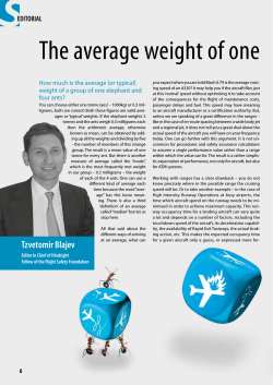


© Copyright 2026