
COVER SHEET
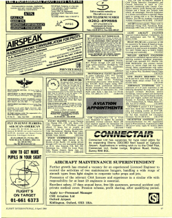
COVER SHEET
Access 5 Project Deliverable
Access 5 Project Office
NASA
P.O. Box 273
Edwards, CA 93523 USA
661-276-2440
661-276-3880 FAX
www.access5.aero
Deliverable Number: FT007
Title: Notional Airspace Operations Demonstration Plan
Filename: FT007_Notional Airspace Operations Plan_v1_FINAL
Abstract: The airspace operations demonstration (AOD) is intended to show that the Access 5 Step 1
functional requirements can be met. The demonstration will occur in two phases. The initial on-range
phase will be carried out in restricted airspace to demonstrate the cooperative collision avoidance (CCA)
functional requirements and to provide risk-reduction for the AOD by allowing the test team to rehearse
some elements of the demonstration mission. The CCA system to be used in these flights is based on
Automatic Dependent Surveillance-Broadcast (ADS-B) which is a commercially-available system by
which airplanes constantly broadcast their current position and altitude to other aircraft and ground
resources over a dedicated radio datalink. The final phase will occur in the national airspace (NAS) and
will be the formal demonstration of the remainder of the proposed functional requirements.
The general objectives of the AOD are as follows:
• Demonstrate that the UAS can aviate in the NAS
• Demonstrate that the UAS can navigate in the NAS
• Demonstrate that the UAS can communicate with the NAS
• Demonstrate that the UAS can perform selected collision avoidance functions in the NAS
• Demonstrate that the UAS can evaluate and avoid weather conflicts in the NAS
• Demonstrate that the UAS can provide adequate command and control in the NAS
In addition to the stated objectives, there are a number of goals for the flight demonstration. The demo
can be accomplished successfully without achieving these goals, but these goals are to be used as a
guideline for preparing for the mission. The goals are:
• Mission duration of at least 24 hours
• Loiter over heavy traffic to evaluate the data block issue identified during the Access 5
Airspace Operations Simulations
• Document the contingency management process and lessons learned
• Document the coordination process for Ground Control Stations (GCS) handoff
• Document lessons learned regarding the process of flying in the NAS
Preliminary planning for a notional mission to achieve the objectives and goals has been prepared. The
planning is intended to serve as a guide for detailed planning of the AOD.
Status: SEIT-Approved
Limitations on use: This document represents thoughts and ideas of the Flight IPT work package team.
It has not been reviewed or approved as an Access 5 project position on this subject. In addition to SEIT
review and comment, the information also needs substantiation through simulation/flight demonstrations.
This notional AOD plan is just that – a notional plan. The dollar amounts provided are rough order of
magnitude (ROM) numbers using FY 06 dollars based on NASA’s billing rate of $150 an hour. This
AOD and the assumptions and conclusions herein are for budgetary and planning purposes only.
i
NASA ACCESS 5
Notional Airspace Operations
Demonstration Plan
Revision 1
19 February, 2006
________________________________
NICHOLAS A. TRONGALE
Access 5 Flight IPT Lead
ii
The following document was prepared by a collaborative team through the noted work package. This
was a funded effort under the Access 5 Project.
ABSTRACT
The airspace operations demonstration (AOD) is intended to show that the Access 5 Step 1
functional requirements can be met. If flown, the demonstration would occur in two phases. The
initial on-range phase would be carried out in restricted airspace to demonstrate the cooperative
collision avoidance (CCA) functional requirements and to provide risk-reduction for the AOD by
allowing the test team to rehearse some elements of the demonstration mission. The CCA system
to be used in these flights is based on Automatic Dependent Surveillance-Broadcast (ADS-B)
which is a commercially-available system by which airplanes constantly broadcast their current
position and altitude to other aircraft and ground resources over a dedicated radio datalink. The
final phase would occur in the national airspace (NAS) and would be the formal demonstration
of the remainder of the proposed functional requirements.
The general objectives of the AOD are as follows:
•
•
•
•
•
•
Demonstrate that the UAS can aviate in the NAS
Demonstrate that the UAS can navigate in the NAS
Demonstrate that the UAS can communicate with the NAS
Demonstrate that the UAS can perform selected collision avoidance functions in the NAS
Demonstrate that the UAS can evaluate and avoid weather conflicts in the NAS
Demonstrate that the UAS can provide adequate command and control in the NAS
In addition to the above stated objectives, there are a number of goals for the flight
demonstration. The demo could be accomplished successfully without achieving these goals, but
these goals are to be used as a guideline for preparing for the mission. The goals are:
•
•
•
•
•
Mission duration of at least 24 hours
Loiter over heavy traffic to evaluate the data block issue identified during the Access 5
Airspace Operations Simulations
Document the contingency management process and lessons learned
Document the coordination process for Ground Control Stations (GCS) handoff
Document lessons learned regarding the process of flying in the NAS
Preliminary planning for a notional mission to achieve the objectives and goals has been
prepared. The planning is intended to serve as a guide for detailed planning of the AOD.
iii
The following document was prepared by a collaborative team through the noted work package. This
was a funded effort under the Access 5 Project.
TABLE OF CONTENTS
Section
Title
Page
TITLE PAGE……………………………………………………………………………………… I
ABSTRACT……………………………………………………………………………………….. II
TABLE OF CONTENTS…………………………………………………………………………. III
1.0
INTRODUCTION................................................................................................... 1
A. Executive Summary…………………………………………………………………. 1
B. Limitations of this Notional Air Space Operations Plan ………………………… 1
C. Background ………………………………………………………………………….. 3
2.0
AOD PLAN/SCOPE .............................................................................................. 3
2.1 GA-ASI DEMONSTRATION SYSTEM AND PLAN/SCOPE .......................... 3
2.1.1
Demonstration System ................................................................... 3
2.1.1.1 Aircraft System............................................................................... 3
2.1.1.2 Ground Control Station (GCS)………………..……………………… 3
2.1.1.3 Operational Base and Aircraft Control……………………………….. 3
2.1.1. 4 Mission Payloads and Flight Requirements…………………………. 4
2.1.2
Proposed Mission Plan………………………………………………… 4
2.1.2.1 Integration/Test Flights………………………………………………… 4
2.1.2.2 Airspace Operations Demonstration (AOD) Flight………………..... 4
2.2 DEMONSTRATION FLIGHT OPERATIONS................................................. 6
2.3 MEDIA AND PUBLIC RELATIONS COORDINATION .................................. 6
2.4 POST-DEMONSTRATION LESSONS LEARNED MEETING ....................... 8
2.5 THE COMMON TOOL…………………………………………………………….. 7
3.0
SCHEDULE .......................................................................................................... 7
4.0
DELIVERABLES................................................................................................... 9
4.1 GA-ASI……………………………………………………………………………… 8
4.2 LMCO………………………………………………………………………............ 9
4.3 MTSI / AEROVIRONMENT……………………………………………… ……… 9
4.4 Pb SOLUTIONS…………………………………………………………….. ……. 9
5.0
GA-ASI PAST PERFORMANCE .......................................................................... 10
5.1
SUMMARY OF PROGRAM EXPERIENCE……………………………..... 9
5.1.1 Unmanned Aircraft………………………………………………… 9
5.1.2 Ground Systems…………………………………………………… 10
5.1.3 Ground Support Equipment (GSE)……………………………….. 10
6.0
NASA DRYDEN PAST PERFORMANCE …………………………………………… 10
7.0
LMCO PAST PERFORMANCE ………………………………………………………. 14
8.0
PRICING ............................................................................................................... 15
8.1
CCA AND AOD MISSION COST PER COMPANY/ORG.…………..
17
iv
The following document was prepared by a collaborative team through the noted work package. This
was a funded effort under the Access 5 Project.
9.0
SUMMARY……………………………………………………………………………….. 16
CHARTS
8.0-1 CCA Flights and AOD Pricing by Company/Organization……………………………15
8.0-2 AOD Mission only Pricing by Company/Organization……………………………….. 16
FIGURES
1.0-1
2.1.2.2-1
2.1.2.2-2
3.0-1
5.0-1
5.0-2
5.0-3
8.0-1
ALTAIR™ Over California Coast………………………………………………. 2
AOD Route of Flight and Altitudes……………………………………………. 5
Aerial View of AOD Operations Route of Flight……………………………… 6
Notional AOD Schedule………………………………………………………… 7
GA-ASI UAV Family…………………………………………………………….. 11
GA-ASI Innovation……………………………………………………………… 12
GA-ASI Family of UA Systems………………………………………………… 13
Altair UA in banked turn………………………………………………………… 16
APPENDICES
A. LMCO Common Tool…………………………………………………………………………. 18
B. WBS……………………………………………………………………………………………. 21
C. GA-ASI, NASA, LMCO, MTSI and Aerovironment Pricing……………………………….. 23
D. Pb Solutions ROM………………………………………………………………………….. 24
E. Access 5 Glossary of Terms………………………………………………………………. 26
v
The following document was prepared by a collaborative team through the noted work package. This
was a funded effort under the Access 5 Project.
Access 5 Project Office
NASA
P.O. Box 273
Edwards, CA 93523 USA
661-276-2440
661-276-3880 FAX
www.access5.aero
INTRODUCTION
A. Executive Summary
The Access 5 Flight Integrated Product Team (IPT) was responsible for conducting flight
demonstrations to exhibit the in-flight performance of critical technologies chosen in support of
the Technology IPT and to duplicate in the flight arena the specified operations identified in each
Access 5 step. General flight requirements were identified by the Technology work packages and
Policy IPT and vetted with the Flight IPT. The Flight IPT developed flight objectives from these
requirements then developed a flight test plan designed to achieve those objectives. All assets
and support for flight activities were procured and coordinated by the Flight IPT with the
exception of some test articles specifically identified or developed by Technology work
packages. The Flight IPT was directly responsible for acquiring flight approval and overall
system integration and test conduct. Flight test activities were documented by the Flight IPT in
the form of reports and data delivered to the interested parties. These responsibilities resulted in
the completion of a Conflict Collision Avoidance (CCA) Technology Demonstration in FY05
and the initial preparation of an Airspace Operations Demonstration (AOD) that was to be
conducted in FY06.
The objective of the CCA Technology Demonstration was to collect data to be used by
the CCA work package to validate that work package’s collision avoidance simulation. Test
conditions accomplished were limited to two participating aircraft (a surrogate UAV and one
piloted intruder). Collision scenarios demonstrated covered a wide range of geometries
including overtaking, head-on, climbing and diving runs. Data was collected onboard each of
the aircraft participating in the demonstration flights, as well as in the ground control station of
the surrogate UAV. Fifty-four test conditions were accomplished during the six demonstration
flights the covered 27 flight hours. The Flight IPT developed a collision avoidance display and
modeling tool designed to assist in planning and execution of the demonstration flights. It used
the flight data generated during the demonstration to validate the generic UAV model included in
the modeling tool.
The AOD planning resulted in the identification of 72 separate flight requirements that
could potentially be demonstrated. A detailed plan was established to demonstrate 66 of the
flight requirements over the course of roughly six missions that would be conducted both within
special use airspace and within the NAS. Neither a detailed plan nor flight approval was
acquired prior to termination of the program. This plan is provided by Access 5 for the use of
potential sponsors of this program or for use by government agencies that would desire to
conduct an airspace operations demonstration.
B. Limitations of this Notional Plan
It must be understood that this notional airspace operations plan is just that – a notional
plan. It assumes that the Altair aircraft will be flown in the proposed configuration for the set
number of hours. The dollar amounts provided are rough order of magnitude (ROM) numbers
1
Access 5 Project Office
NASA
P.O. Box 273
Edwards, CA 93523 USA
661-276-2440
661-276-3880 FAX
www.access5.aero
good for FY 06. They are based on NASA’s billing of $150 per hour which gives a very accurate
time in space cost picture to execute this plan as written. If this plan were to be flown, the
sponsoring agency would have to submit a statement of work (SOW) to each of the participating
organizations who would in turn need to submit a binding proposal to support the SOW. The
purpose of this notional AOD is to show what can be accomplished in FY 06 dollars, using the
Altair aircraft with Automatic Dependent Surveillance – Broadcast (ADS-B) installed and flying
a projected 15 flight hours for CCA testing and performance gathering and a 30 hour AOD in the
NAS.
Figure 1.0-2 ALTAIR™ Over California Coast.
2
C. Background
The AOD plan was developed under the following assumptions of specific organizations
fulfilling specific roles and responsibilities. This plan was developed under NASA program
management by the Flight IPT. The ALTAIR™ (see Figure 1.0-1) UAS was chosen as the
demonstration testbed based on its operating envelope, system architecture and payload
capabilities. GA-ASI was selected to perform the needed UAS modification and conduct the
flight activities based on their ownership of the testbed and extensive history of UAS experience.
Lockheed Martin Aeronautical Systems of Fort Worth Texas was selected to aid in cooperative
collision avoidance (CCA) test article integration and test support based on their development of
the CCA system and previous support of the CCA flight demonstration. NASA’s Dryden Flight
Research Center was chosen as the responsible test organization based on their previous
safety/flight approval and test plan development on the CCA flight demonstration. NASA’s GIII Gulfstream was selected as the intruder aircraft for the CCA demonstration elements based on
its previous support of the CCA flight demonstration and all vehicle modifications already being
in place to support the CCA portions of the demonstration.
2.0
AOD PLAN/SCOPE
This plan responds to Access 5 Leadership request for the Flight IPT to produce a
notional airspace operations plan with the ALTAIR™ aircraft as the test platform.
2.1
GA-ASI DEMONSTRATION SYSTEM AND PLAN/SCOPE
2.1.1
Demonstration System
2.1.1.1 Aircraft System
GA-ASI proposed to use the Predator B derivative, ALTAIR™ to perform the AOD.
ALTAIR™ is a company-owned aircraft system, operated under a joint use agreement with
NASA. ALTAIR™ endurance is 32 hours at high altitude (above 50,000’). This performance is
in excess of that required for the AOD. ALTAIR™ characteristics and flight data are
documented in ALTAIR™ Experimenter’s Handbook 10-15-01, on file with NASA Dryden and
can be obtained from GA-ASI upon request.
2.1.1.2 Ground Control Station (GCS).
The aircraft is controlled by a GA-ASI GCS and is flown by an experienced pilot.
Payloads are programmed, monitored and controlled by an experienced payload control
technician. The GCS includes the ground data terminals required for both line-of-sight and
satellite “over the horizon” ALTAIR™ control. The GCS also includes all the equipment
required to plan the AOD missions, and if necessary, re-program ALTAIR™ while airborne to
change the operation if required. The GCS also includes all communications equipment required
for safe operation of the aircraft in controlled airspace.
2.1.1.3 Operational Base and Aircraft Control
GA-ASI planed to conduct the AOD from one of its flight operations facilities at Gray
Butte or El Mirage, California. Therefore, any deployment of the aircraft and GCS would not be
3
The following document was prepared by a collaborative team through the noted work package. This
was a funded effort under the Access 5 Project.
required. Ku-Band satellite equipment and services would be provided by a subcontractor with
experience working with unmanned aircraft. Bushtex, Inc. under contract to GA-ASI, has
successfully accomplished this task for GA-ASI in the past. Line-of-sight ALTAIR™ control is
provided by GA-ASI using ALTAIR™’s GA-ASI proprietary C-Band data link system.
2.1.1.4 Mission Payloads and Flight Requirements
The Mission Payloads integrated into ALTAIR™ and the flight requirements are as
defined by Access 5. ADS-B payload installation onboard ALTAIR™ is shown in Figures 2.1-1.
ADS-B: ADS-B is an air traffic surveillance technology. The system concept is that all,
or most, aircraft in an area automatically and continually (i.e. roughly once per second) broadcast
several digital data packets which together contain the aircraft's 24 bit address [unique airframe
identification], flight identification [call sign], GPS derived latitude and longitude, barometric [or
Mode C] altitude plus 3 dimensional velocity, i.e., rate of climb/descent, direction and speed
over a dedicated data link.
The broadcast ADS-B packets are received by aircraft equipped with an ADS-B data
receiver. The derived data provides a real time cockpit display of traffic information; similar to
the ground air traffic management systems except that the traffic is shown in relation to own
aircraft's intended track.
2.1.2 Proposed Mission Plan
2.1.2.1 Integration/Test Flights
A series of eight integration/test flights not to exceed 25 hours would be conducted from
GA-ASI’s base of operations in the High Dessert. These flights will be conducted by GA-ASI
and are independent of the 30 operational hours described in the AOD plan below. The purpose
of the integration/test flights is to ensure readiness of sensor systems and to demonstrate the
CCA functional requirements. Visual Meteorological Conditions (VMC) is required for all
flights.
2.1.2.2 AOD Flight (~30 hours)
The AOD Notional mission was designed to demonstrate a vision of routine UAS access
to the NAS by combining elements of typical UAS missions into one maximum endurance flight.
Figure 2.1.2.2-1 addresses the AOD route of flight and altitudes.
4
The following document was prepared by a collaborative team through the noted work package. This
was a funded effort under the Access 5 Project.
Leg
Route of Flight
1
Enter NAS
Grey Butte Launch
Transit to R2515
Climb in R2515
2
Altitude Climb/Descend
NAS Transit A to B
R2515 to Prescott Area
G-III Files Similar Plan
Cruise Altitude
FL0 to 430
FL0 to 100
FL100
FL100 to 430
FL430
FL430
3
Loiter in NAS
Prescott Area
FL430
Arrive & Depart at Predefined Times
G-III Remains in Vicinity
FL430
4
NAS Transit A to B to C
Prescott, New Mexico to Montana
AVCS Handoff to Ft. Huachuca & Back
Non-Standard Flight Plan (Lg. Heading Change)
Altitude Changes
FL430 to 450+
FL430 to 450+
5
Wx Reroute
Wyoming
Operator Requests Real-Time Reroute
FL450+
6
NAS Transit to Real-Time Station
In-Flight ID of Loiter Point in Western Montana
Arrive at Predefine Time Depart at Non-Defined Time
FL450+
7
NAS Transit from Real-Time Point
Montana to Oregon
FL450+
8
Loiter in NAS
SW Oregon
Arrive & Depart at Non-Predefined Times
FL450+
9
10
NAS Transit
Loiter Over Traffic Route
Yosemite Area
FL450+
FL450+
11
Transit to Range
FL450+
12
Exit NAS
Enter R2515
Descend in R2515
Transit to Grey Butte & Land
FL450+ to 0
FL450+
FL450+ to 100
FL100 to 0
Figure 2.1.2.2-1 Notional Airspace Operations Demo Route of Flight and Altitudes
5
The following document was prepared by a collaborative team through the noted work package. This
was a funded effort under the Access 5 Project.
Figure 2.1.2.2-2 Aerial View of AOD Operations Route of Flight
2.2
DEMONSTRATION FLIGHT OPERATIONS
GA-ASI would coordinate Ku coverage for all flights. The demonstration will be
conducted using Ku-Band SATCOM and C-Band Line of Sight data links and a chase plane, if
required by COA. The sponsor will be required to obtain a COA.
2.3
MEDIA AND PUBLIC RELATIONS COORDINATION
6
The following document was prepared by a collaborative team through the noted work package. This
was a funded effort under the Access 5 Project.
Media releases would be jointly coordinated through the sponsor and participating
companies. No releases are permitted without concurrence from all entities. GA-ASI would
accommodate, within reason, requests by the sponsor for site demonstrations and media events.
7
The following document was prepared by a collaborative team through the noted work package. This
was a funded effort under the Access 5 Project.
2.4
POST-DEMONSTRATION LESSONS LEARNED MEETING
The sponsor would arrange and host a meeting, as required, to discuss lessons learned
from the demonstration, providing feedback to the sponsor and receiving feedback to facilitate
future planning and operations. This meeting may be conducted in person or by conference call
and will consist of presentations from all three parties.
2.5
THE COMMON TOOL
The primary purpose of the common tool for the AOD is to communicate with the
ALTAIR™ ground station and display ADS-B information to the operator. Specific features
include reception of aircraft state information, decision logic for collision avoidance and a
display/interface for the collision avoidance systems. Another possible application of the
common tool could be to act as a virtual intruder to allow evaluation and testing of the display
without having to add the cost of flying an intruder during any in-flight integration testing. The
common tool provides the flexibility and mobility to insert display applications or provide
simulations of many different platforms into multiple test environments.
3.0
SCHEDULE
It would take approximately eight months from contract award/funds transfer to complete
the AOD.
Task Number*
1
2
3
4
5
6
7
8
9
10
11
13
14
Task
Receive Statement of Work
Receive RFP
Submit Proposal
Contract Award / Funds Transfer
Complete Engineering and SIL Work-3 months
Complete Integration of Payload- 1
month
Completion Ground Testing- 2 wks
AFSRB for flights-1 day
Completion flight testing -2
wks
Completion CCA flights on NASA range- 3 wks
AFSRB for AOD-1 day
Complete AOD Mission- 1
wk
System de-integration/pack-up
equipment
Complete Final Report
Time Line
Total
Days
D- 49
D- 35
D- 21
D+ 00
D+ 90
0
0
0
49
139
D+ 120
D+ 127
D+ 127
169
176
176
D+ 141
D+ 162
D+162
190
211
211
D+ 169
218
D+ 178
D+ 220
225
267
* Task Numbers do not necessarily correspond to the WBS numbering system
Figure 3.0-1 Notional AOD Schedule
8
The following document was prepared by a collaborative team through the noted work package. This
was a funded effort under the Access 5 Project.
4.0
DELIVERABLES
4.1
GA-ASI will integrate the ALTAIR™ UAS with ADS-B, and provide the GCS,
associated ground support equipment (GSE) and spares required to execute the SOW from GAASI facilitates for the period “on or about” of six months after contract award until the
completion of the demonstration. For the CCA portion of this plan GA-ASI will provide:
I. Integration and tests of the following payloads:
a. ADS-B -- GFE
ADS-B to be integrated with pilot-in-the-loop only –Auto-ADS-B not
part of this effort.
II. Engineering Support for Simulation Phase to include:
a. Project Oversight and Coordination
b. System and analysis engineering support to refine present aircraft
models and provide technical coordination with Access 5
simulation teams for debugging and implementation.
c. System and analysis engineering support to create AVCS model
and provide technical coordination for Access 5 simulation teams
for debugging and implementation.
III. Installation Design and SIL Checkout
a. Project Oversight and Coordination.
b. H/W & S/W engineering for incorporating protocol interface
translators between sensor suite and Gen. P/Load Port channel,
ROA & AVCS.
c. Mechanical design of sensor equipment location, installation
hardware and antenna mountings.
d. Electrical & Physical cable harness design.
e. Manufacturing harness build.
f. Write Test Plan
g. Assemble and test in GA--ASI Rancho Bernardo System
Integration Lab (SIL) facility: 2 week period.
IV. Aircraft/AVCS Ground Checkout and Flight/Test Readiness Review
a. Project Oversight and Coordination.
b. Aircraft/AVCS Ground Checkout conducted at GA-ASI El
Mirage Flight Test Center EMFTC over two weeks.
c. Provide two Mechanics and two Avionics Technicians for NTE
10 days.
d. Prepare support and attend FRR NTE 50 hrs. Includes aircraft &
payload flight test planning.
V. Configuration Management
Per GA-ASI company procedure.
VI. System Familiarization and Training Support NTE 300 hours.
VII. Flight Mission
a. Project Oversight and Coordination.
b. NTE 10 flight days for 35 flight hours
9
The following document was prepared by a collaborative team through the noted work package. This
was a funded effort under the Access 5 Project.
c. Provide two Mechanics and two Avionics Technicians support
for 5 weeks.
d. Provide two pilot/operator crews for 10 flight days.
VIII. Post Flight Analysis Support
a. Project Oversight and Coordination.
b. Equipment removal and ROA normalization.
For the AOD NAS portion of this demonstration GA-ASI will provide:
B.
C.
D.
E.
F.
G.
Total Flight Hours: NTE 30 hrs or max endurance.
Flights will be flown at completion of CCA phase as stand alone option.
Flights will be conducted from Gray Butte or El Mirage if situation requires.
Altitude and flight speed will be determined by GA-ASI.
Flight Mission shall be flown over a 5 day period.
Leased GA-ASI equipment will include GCS, GDT, and ALTAIR aircraft
including GSE and fuel.
H. Ku support will be provided under a separate contract.
I. 30 hours of chase plane time is required for flights below 18,000 feet.
4.2
LMCO will supply and support the Common Tool for the AOD. The purpose of
the Common Tool is to communicate with the ALTAIR™ ground station and display ADS-B
information to the operator. The common tool will communicate externally via UDP over
Ethernet using multiple ports. The Common Tool will also act as a virtual intruder to allow
evaluation and testing of the display without having to add the cost of flying an intruder along
with the Altair during any in-flight integration testing.
4.3
MTSI and Aerovironment will produce the test report and final report.
4.4
Pb Solutions will produce an AOD Plan brief and brief FAA Headquarters and
Regional Facilities responsible for the airspace that the ALTAIR™ will fly in.
5.0
GA-ASI PAST PERFORMANCE
General Atomics Aeronautical Systems Inc. (GA-ASI) was formed in 1992 to design,
produce, operate, and support unmanned aerial vehicles (UAVs). Figures 5.0-1 through 5.0-3
summarize the family of UAV systems we have developed over the past 15 years.
It has invested heavily in developing advanced technology UAVs that are now in service
with the U.S. Government including the U.S. Air Force, U.S. Army, U.S. Navy, NASA and other
Government agencies. It has also supplied UAVs to foreign governments.
5.1
SUMMARY OF PROGRAM EXPERIENCE
5.1.1 Unmanned Aircraft— GA-ASI has designed and built over 150 aircraft over the
last 15 years. Many of these aircraft were designed and built on company IR&D funds. All
aircraft designs except the Prowler variant are in use by their customers today. Predator and
Predator B currently comprise over 90% of its production. Predator started as an ACTD and
transitioned to production in 1996 under the US Air Force.
10
The following document was prepared by a collaborative team through the noted work package. This
was a funded effort under the Access 5 Project.
In 2000 to 2001, GA-ASI developed Predator B with internal funding (Figures 5.0-2 and
5.0-3). The U.S. Air Force purchased its company-developed Predator B aircraft system in 2001
and has since ordered 20 production versions. GA-ASI jointly developed ALTUS and Predator B
with NASA; these two UAVs were developed for NASA’s Environmental Research Aircraft
Sensor Technology (ERAST) program. In 2003, the company developed the I-GNAT ER
(extended range) for the U.S. Army (Army I-GNAT).
GA-ASI has invested heavily in production facilities and tooling to meet increasing
demand for our products on priority Government programs, and will leverage on this increased
capability to supply future orders.
5.1.2 Ground Systems—GA-ASI has developed or modified existing Ground Control
Systems (GCS) for each of its UAV customers. Using a common architecture and modular
design we have progressively reduced the size, weight, and dimensions of our GCS and
associated ground systems to make them more portable and transportable tailored to the needs of
our customers. In addition to GCS systems, we have designed, developed, produced, and fielded
mobile and portable GCSs (MGCS and PGCS), Ground Data Terminals (GDT), portable GDTs
(PGDT), and Remote Video Terminals (RVTs) that are lightweight and portable. GA-ASI
tailored these ground systems to customer specifications and desires, and continues to make our
ground systems simpler, more reliable and more mobile to reduce logistic footprint.
5.1.3 Ground Support Equipment (GSE)—As technology has advanced and
requirements for mobility and reduced logistic footprint have grown, GA-ASI progressively
reduced the need for unique GSE. For example, engines on our aircraft are started on internal
power. Its aircraft do not require external power, air, etc., to start and maintainability design
places access to aircraft components where they are accessible by personnel standing on the
ground. GA-ASI continues to ruggedize its GSE and eliminate hardware that requires GSE.
6.0
NASA/DFRC PAST PERFORMANCE
The Dryden Flight Research Center (DFRC) has been responsible for the research and
testing of atmospheric air vehicles for NASA. The over five decades of flight test activity
include many X-series aircraft, space shuttle landing tests and numerous UAS. The recent
Access 5 CCA testing was led by DFRC. The test planning, flight safety and flight approval for
CCA tech demo were all structured to directly apply to gaining flight approval for the AOD.
DFRC’s G-III Gulfstream was modified to fully support testing of the CCA system.
Modifications to the G-III included installation of the CCA system and all required
instrumentation. No additional modifications are required for the G-III to support the AOD.
11
The following document was prepared by a collaborative team through the noted work package. This
was a funded effort under the Access 5 Project.
Figure 5.0-1 GA-ASI UAV Family. GA-ASI developed a family of unmanned aircraft systems based
on planned, controlled growth and continued upgrade of a successful, open system architecture.
12
The following document was prepared by a collaborative team through the noted work package. This
was a funded effort under the Access 5 Project.
Figure 5.0-2 GA-ASI Innovation. In less than 10 years we became a recognized world leader in development and
production of UAV systems and an industry pioneer in payload and weapons integration.
13
The following document was prepared by a collaborative team through the noted work package. This
was a funded effort under the Access 5 Project.
EXTERNAL RELEASE IS SUBJECT NASA REVIEW AND APPROVAL
Figure 5.0-3 GA-ASI Family of UA Systems. GA-ASI has produced 10 different unmanned aircraft and the ground systems to support them in the past
10 years. Eight of its 10 aircraft are in operational service today with U.S. and foreign customers; all our ground systems are operational today.
14
The following document was prepared by a collaborative team through the noted work package. This was a funded effort under the Access 5 Project.
EXTERNAL RELEASE IS SUBJECT NASA REVIEW AND APPROVAL
7.0
LMCO PAST PERFORMANCE
Lockheed Martin Aeronautics Advanced Development Program flight demonstrations
group has been involved with numerous flight demonstrations providing integration insight and
support and providing flight test support during flight test execution.
One particular flight demonstration that Lockheed Martin was the prime integrator for
was the Automatic Air Collision Avoidance System (ACAS) flight demonstration. For the
ACAS flight demonstration, the integration planning identified that a ground station would be
required that would act as a virtual aircraft and communicate the necessary information over the
data link hardware to the host aircraft simulation so that the ACAS algorithm could be evaluated
on the aircraft hardware in the simulator environment. The ground station allowed the flexibility
to set up the virtual aircraft in all kinds of geometries with respect to the host aircraft and
allowed the ability to repeat identical runs during testing. In addition, the ground station was
utilized in the initial flights to validate the system and provide a safe evaluation. This was a
requirement of the safety plan before two aircraft were allowed to perform an ACAS run. The
ground station also allowed the flight test group to perform test runs at conditions that would not
be allowed for two actual aircraft. Also, the cost savings and ease of running the ground station
as opposed to having two aircraft set up for the same kind of runs was dramatic.
From the development produced in the ground station on ACAS, Lockheed Martin
Aeronautics proposed that the ground station application could be modified to provide a mobile
display for the multiple test environments and collision avoidance applications planned for the
Access 5 CCA development and demonstrations. Thus, the concept of the common tool was
conceived. The CCA display was developed and the external interface to the common tool was
defined to allow TCAS and ADS-B information to be brought in via the Proteus ground station
by way of the link to the Proteus aircraft. The CCA display was integrated into the Proteus
ground station control room and was an integral part of the collection and display of the collision
avoidance data for all of the Access5 CCA flight technology demonstration flight test runs. LM
personnel provided integration support and debugged anomalies with the common tool during
ground test and preliminary integration check out flights.
Lockheed Martin personnel have the experience to again tailor the common tool to the
requirements prescribed for the notional AOD demonstration.
15
EXTERNAL RELEASE IS SUBJECT NASA REVIEW AND APPROVAL
8.0
PRICING
The total cost to fly this CCA Demo and AOD is $2,293,000.00. A complete
breakdown of work tasks and can be found in the WBS, Appendix B. Charts 8.0-1 and 8.0-2
depict costs per company/organization for both the CCA demo and AOD flight in the NAS.
8.1
CCA Demo and AOD Mission Cost per Company/Org
GA-ASI
LMCO
NASA
MTSI /
Aerovironment
Pb Solutions
CCA Demo
AOD Mission
CCA Demo
AOD Mission
CCA Demo
AOD Mission
$ 900,000.00
$ 97,000.00
$ 310,950.00
$ 54,300.00
$ 637,800.00
$ 38,850.00
CCA Demo
AOD Mission
AOD Mission
Total
$ 195,150.00
$ 42,450.00
$ 16,600.00
$2,293,100.00
2500000
Total Cost
$2,293,100.00
2000000
1500000
$997,000.00
1000000
$676,650.00
500000
$365,250.00
$237,600.00
$16,600.00
0
1
GA-ASI
Chart 8.0-1
2
3
NASA
LMCO
4
MTSI/Aerovironment
CCA/AOD Cost Per Company/Organization
16
5
Pb Solutions
6
EXTERNAL RELEASE IS SUBJECT NASA REVIEW AND APPROVAL
Stand Alone AOD Mission Cost
$300,000.00
$249,350
$250,000.00
$200,000.00
$150,000.00
$100,000.00
$97,000.00
$54,450.00
$42,450.00
$50,000.00
$38,850.00
$16,600.00
$-
Total
GA-ASI
LMCO
MTSI /
Aerovironment
NASA
Pb Solutions
Chart 8.0-2 Stand Alone AOD Mission Cost
9.0
SUMMARY
The AOD was intended to show that the Access 5 Step 1 functional requirements can be
met. The demonstration would occur in two phases. The initial on-range phase would be carried
out in restricted airspace to demonstrate the CCA functional requirements and to provide riskreduction for the AOD by allowing the test team to rehearse some elements of the demonstration
mission. The CCA system to be used in these flights is based on ADS-B which is a
commercially-available system by which airplanes constantly broadcast their current position
and altitude to other aircraft and ground resources over a dedicated radio datalink. The final
phase will occur in the NAS and will be the formal demonstration of the remainder of the
proposed functional requirements.
The general objectives of the AOD are as follows:
•
•
•
•
•
Demonstrate that the UAS can aviate in the NAS
Demonstrate that the UAS can navigate in the NAS
Demonstrate that the UAS can communicate with the NAS
Demonstrate that the UAS can perform selected collision avoidance functions in the NAS
Demonstrate that the UAS can evaluate and avoid weather conflicts in the NAS
17
EXTERNAL RELEASE IS SUBJECT NASA REVIEW AND APPROVAL
•
Demonstrate that the UAS C2 provide adequate command and control in the NAS
The total cost to fly CCA/AOD is $2,293,000.00. However, the final phase, the NAS
demonstration can be flown on its own for a cost of $249,350.00.
Figure 8.0-1
ALTAIR™ UA in banked turn.
18
EXTERNAL RELEASE IS SUBJECT NASA REVIEW AND APPROVAL
Appendix A THE COMMON TOOL
The common tool provides the flexibility and mobility to insert display applications or
provide simulations of many different platforms into multiple test environments. The intent of
the common tool is for it to be open to all participants that would want to utilize the tool.
Platform developers could insert their own proprietary models themselves and then bring the tool
to the test environment and send the aircraft state information over the external interface. The
common tool software is developed using the software application tool known as D-Six. D-Six
is a PC based simulation environment, developed by Bihrle Applied Research, that combines the
graphical interface, analysis tools and flexibility of the simulation development environment
with the computational power needed to run complex engineering simulations at real time. The
D-Six setup is illustrated in Figure A-1.
Figure A-1. D-Six Tool Illustration
The collision avoidance display developed as part of the common tool for the CCA
Technology Demonstration had several options for the viewer/user to select from. The display
allowed the user to choose either TCAS data or ADS-B data for display. A simplified version of
the TCAS Collision Avoidance System (CAS) logic was also incorporated as an option to select
on the collision avoidance display (Ground CAS logic). The user can select either the ground
CAS logic (CAS logic incorporated in the common tool) or take the CAS logic data from the
actual TCAS hardware. The user also has the option of selecting a situational awareness display
or CAS display when ADS-B data has been requested for display. The overall collision
avoidance display processing in the common tool is shown in Figure A-2.
19
EXTERNAL RELEASE IS SUBJECT NASA REVIEW AND APPROVAL
CA Display Functions Integrated with Aircraft System
Link
Common Tool 1
Display
Processing
Gnd
CAS
ADS-B
Data
Sensor
T
Data
A
Processing
Ground
CAS
Logic
CAS Display
ADS-B Data
AND NOT
Gnd CAS
SA Display
A/C Data
ADS -B
TCAS
Network
Processing
GPS
Processing
Data
Storage
T = TCAS formatted data
A = ADS -B formatted data
Aircraft Platform
Ground Station
PC
Time
Garmin
GPS16
PC
Figure A-2 Collision Avoidance Display Processing
The intent of the common tool was to be able to reuse the collision avoidance display
software in multiple software products and lab testing environments with little or no
modification to the common tool interfacing source code.
The common tool also provides a generic UAS model that allows for selectable limits of
six aircraft performance related parameters. This model could act as a virtual intruder and
provide data relative to the host vehicle to drive the collision avoidance display. The virtual
intruder setup is defined in Figure A-3. GPS time is also supplied to the common tool to provide
for an accurate, reliable, and consistent time stamp that can be associated with the data coming in
and being processed.
The primary purpose of the common tool for the AOD is to communicate with the
ALTAIR™ ground station and display ADS-B information to the operator. The common tool
has been identified to communicate externally with the Altair® ground station via RS-422 or RS232. A secondary purpose of the common tool is to act as a virtual intruder to allow evaluation
and testing of the display without having to add the cost of flying an intruder along with the
ALTAIR™ during any in-flight integration testing.
20
EXTERNAL RELEASE IS SUBJECT NASA REVIEW AND APPROVAL
CT Virtual Intruder Option to support Aircraft Flight Test Prep
Common Tool 2
Human Pilot
(USB Joystick)
Pilot Model
Autopilot
Sensor
Models
Aircraft 6 -dof
Simulation
(Outer Loop)
Data
Packaging
Data
Storage
CA Display
Functions
Network
Processing
PC
A/C Data
Link
Aircraft Platform
Ground Station
PC
Figure A-3 Virtual Intruder Setup
21
GPS
Processing
Time
Garmin
GPS16
EXTERNAL RELEASE IS SUBJECT NASA REVIEW AND APPROVAL
Appendix B WBS
WBS
1.5.1
Name
AOD Flight Test
1.5.1.1
1.5.1.1.1
1.5.1.1.2
1.5.1.1.3
1.5.1.1.4
1.5.1.1.5
1.5.1.1.6
1.5.1.1.7
1.5.1.1.8
Develop Test Plan
Define Test Objectives
Develop Data Analysis Plan
Develop test scenarios
Perform safety/hazard analysis
Write Test Plan
FRR
Conduct Flight Approval
Approve Test Plan
1.5.1.2
1.5.1.2.1
1.5.1.2.2
1.5.1.2.3
1.5.1.2.4
Obtain Test Facilities (CCA increment)
Define Facility requirements
Obtain Maintenance Facilities
Obtain Office Space & Supplies
Obtain AVCS facilities
1.5.1.3
1.5.1.3.1
1.5.1.3.2
1.5.1.3.3
1.5.1.3.4
Coordinate Airspace
Down select test ranges
Phone Interviews with range manager
Brief Range coordinator with test plan
Get approval/authorization to conduct test
1.5.1.4
1.5.1.4.1
1.5.1.4.2
Coordinate Frequency Spectrum
Control Link(s)
Sensors
1.5.1.5
1.5.1.5.1
1.5.1.5.2
Procure Test Platform(s)
Platform & AVCS Selection
Intruder Aircraft Selection
1.5.1.6
1.5.1.6.1
1.5.1.6.2
1.5.1.6.3
1.5.1.6.4
1.5.1.6.5
1.5.1.6.6
1.5.1.6.7
1.5.1.6.8
Integrate Components
Common Test Tool Development
Platform Specific Interface Coord
Supply Simplified Non-Prop Model
Install Instrumentation
Install CCA subsystem
Install C3 subsystem
Install Communication subsystem
Configuration Control
1.5.1.7
1.5.1.7.1
1.5.1.7.2
Ground Test complete system
Develop specific ground test cases
Prepare hardware/software for ground test
22
EXTERNAL RELEASE IS SUBJECT NASA REVIEW AND APPROVAL
1.5.1.7.3
1.5.1.7.4
Execute ground testing
Document results and improvement needs
1.5.1.8
1.5.1.8.1
1.5.1.8.2
1.5.1.8.3
1.5.1.8.4
Conduct Training
Train Maintainers on the system
Train Flight crews on the system
Train Test engineers on the system
Conduct mission training
1.5.1.9
1.5.1.9.1
1.5.1.9.2
1.5.1.9.3
1.5.1.9.4
1.5.1.9.5
Execute Flight Test
Conduct Tech Review
Conduct Pre-Brief
Conduct CCA Flight Test
Conduct Prep Flight Test
Conduct AOD Flight Test
1.5.1.10
1.5.1.10.1
1.5.1.10.2
1.5.1.10.3
1.5.1.10.4
1.5.1.10.5
1.5.1.10.6
1.5.1.10.7
Conduct Analysis
Retrieve data from test platform & Intruder aircraft
Retrieve data from AVCS
Retrieve ARSR radar data from FAA ARTCC
Package sensor & TSP data
Analyze Flight Data to confirm test objectives met
Conduct CCA Analysis
Catalogue Data and Compile Tracking Matrix
1.5.1.11
1.5.1.11.1
1.5.1.11.2
1.5.1.11.3
1.5.1.11.4
1.5.1.11.5
1.5.1.11.6
1.5.1.11.7
Write Test Report
Write Quick Look Report
Write Interim Report
Write Final Report
Analysis Coordination
Document Coordination
Publication
CCA Reporting
1.5.1.12
1.5.1.12.1
1.5.1.12.2
1.5.1.12.3
Management
Coordination
Tracking
Reporting
23
EXTERNAL RELEASE IS SUBJECT NASA REVIEW AND APPROVAL
Appendix C GA-ASI, LMCO, NASA, Pb Solutions, MTSI and Aerovironment Pricing
Combined CCA Demo AOD Mission Cost per Company / Organization
GA-ASI
CCA Demo
AOD Mission
$ 900,000.00
$ 97,000.00
LMCO
CCA Demo
AOD Mission
$ 310,950.00
$ 54,300.00
NASA
CCA Demo
AOD Mission
$ 637,800.00
$ 38,850.00
MTSI / Aerovironment
CCA Demo
AOD Mission
$ 195,150.00
$ 42,450.00
Pb Solutions
AOD Mission
Total
$ 16,600.00
$2,293,100.00
Total
$
$
$
$
$
$
Stand Alone AOD Mission Cost
GA-ASI
LMCO
MTSI / Aerovironment
NASA
Pb Solutions
24
97,000.00
54,450.00
42,450.00
38,850.00
16,600.00
249,350
EXTERNAL RELEASE IS SUBJECT NASA REVIEW AND APPROVAL
Appendix D Pb Solutions ROM
February 3, 2006
Reference; Pb06-FT007
National Aeronautics and
Space Administration
Dryden Flight Research Center
P.O. Box 273 MS 2344
Edwards, CA 93523-0273
Attention:
Mr. Mike Sakahara
Subject:
Cost to Provide Briefings on Technology Flight Demonstration for CCA
and Airspace Operations Demonstration (AOD) Plan to FAA.
Reference:
Attachment:
a) SEIT Request to provide Costing for AOD Plan briefings to FAA
None
Dear Mr. Sakahara,
In response to the request to provide a cost estimate to provide briefing to the FAA on the
Technology Flight Demonstration for CCA and Airspace Operations Demonstration (AOD)
Plan, Pb Solutions is pleased to provide the following:
1. Labor
2. Travel
$14,000
$ 2,600
$16,600
In order to provide a potential customer with the tasks associated with this estimate, Pb Solutions
provides the following:
2. Breakdown of cost to provide briefings on Technology Flight Demonstration for
CCA and Airspace Operations Demonstration (AOD) Plan to FAA.
A. Total labor hours to prepare brief and handouts: 16 hours
B. Labor hours associated with providing briefs to FAA: 77 hours
Pb Solutions, 250 E. Church St. Elmhurst, IL 60126
Phone: 858-414-5167
25
EXTERNAL RELEASE IS SUBJECT NASA REVIEW AND APPROVAL
Pb Solutions will provide:
I. A Power Point brief and handouts explaining the Technology Flight
Demonstration for CCA and Airspace Operations Demonstration
(AOD) Plan:
II. An expert briefer with extensive experience in the background and
development of the AOD plan at all four briefs.
This cost estimate for the proposed AOD is for budgetary and planning purposes only and does
not constitute a formal offer. It is based on FY-06 dollars.
This proposal includes data that shall not be disclosed to any third party and shall not be
duplicated, used or disclosed, in whole or part, for any purpose other than to evaluate this
program opportunities.
The choice of Pb Solutions is the low risk, high payoff solution to the request. If you have any
questions regarding this communication, please contact me at (858) 414-5167.
Pb Solutions is a registered Disabled Veterans Business Enterprise (DBVE # 32546).
Sincerely,
Nicholas A. Trongale
President
Pb Solutions
Pb Solutions, 250 E. Church St. Elmhurst, IL 60126
Phone: 858-414-5167
26
EXTERNAL RELEASE IS SUBJECT NASA REVIEW AND APPROVAL
Appendix E Access 5 Glossary of Terms
Purpose: This Glossary was compiled to promote a common understanding of the most
ambiguous terms used by the members of the Access 5 Group during their Integration of
Unmanned Aircraft into the National Airspace system (NAS) effort.
AIRCRAFT − A device that is used, or intended to be used, for flight in the air.
AIRCRAFT CONTROL STATION (ACS) − The equipment from which the pilot of an
unmanned aircraft (UA) remotely controls and monitors the UA flight and mission activity.
AIRWORTHINESS - The condition in which the UAS conforms to its type certificate and is
in condition for safe operation.
AUTONOMOUS OPERATIONS – The method whereby the control of an unmanned aircraft
is accomplished by an onboard self-contained flight management control system using
previously inserted data.
CERTIFICATE OF AUTHORIZATION OR WAIVER (COA) - An FAA grant of approval
for a specific operation, for a specified time period.
CIVIL AIRCRAFT – An aircraft other than public aircraft.
CODE OF FEDERAL REGULATION – A codification of the general and permanent rules
published in the Federal Register by the Executive department and agencies of the Federal
Government. Pertinent to aviation are those rules issued by the department of Transportation
and the Federal Aviation Administration (see Title 14 Code of Federal Regulations parts 1499).
COLLISION AVOIDANCE (CA) - Averting physical contact between an aircraft and any
other object or terrain.
COMMAND LINK - The element of the unmanned aircraft system used to transfer a pilot’s
intent to the unmanned aircraft. The uplink portion of the control link between a pilot and the
unmanned aircraft.
COMMUNICATIONS LINK - The element of the unmanned aircraft system used for voice
and/or digital communications between a UA pilot and ATC. Includes an uplink and downlink
component. Often implemented as part of the control link.
CONTROL LINK - The element of the unmanned aircraft system used by the UA pilot to fly
the aircraft. Consists of the command link (uplink) and the status link (downlink).
27
EXTERNAL RELEASE IS SUBJECT NASA REVIEW AND APPROVAL
COOPERATIVE SENSE AND AVOID SYSTEM (CSAS) – A system capable of
communicating with systems on board other aircraft, or other airborne objects in order to
facilitate detection or coordinate resolution maneuvers, or both.
DATA LINK - A term referring to all links between an unmanned aircraft and the aircraft
control station. It includes control, communications and payload links..
EQUIVALENT LEVEL OF SAFETY (ELOS) - An evaluation, often subjective, of a system
and/or operation to determine the acceptable risk to people and property.
FLIGHT RECOVERY SYSTEM - Incorporating some feature for automatically
counteracting the effect of an anticipated possible source of failure.
HIGH ALTITUDE LONG ENDURANCE (HALE) – An unmanned aircraft capable of
performing a specific mission at a specified altitude at or above flight level 450 over a period of
24 hours or more.
HOLDING − A predetermined maneuver that keeps aircraft within a specified airspace. Also
used during ground operations to keep aircraft within a specified.
LATENCY - The time incurred between two particular interfaces. The total latency is the
delay between the true time of applicability of a measurement and the time that the
measurement is reported at a particular interface (the latter minus the former).
LINK FAILURE – The loss of command and/or status link between a pilot and an unmanned
aircraft.
LINK INTERRUPTION – An occurrence when either the unmanned aircraft or the aircraft
control station detects the loss of the command and/or status link. Link Interruption becomes
Link Failure if the loss of link lasts longer than a predefined interval.
LOITERING – (See HOLDING).
LOST COMMUNICATIONS − Loss of the ability to communicate by radio.
MODEL AIRCRAFT - A model aircraft is a non-human-carrying device capable of sustained
flight in the atmosphere and is intended to be used exclusively for recreational or competition
activity. The maximum takeoff weight of a model aircraft, including fuel, is 55 pounds, except
for those flown under the AMA Experimental Aircraft Rules.
NON-COOPERATIVE SENSE AND AVOID – A system that is capable of detecting
aircraft, or other airborne objects that do not have a cooperative sense and avoid system.
PAYLOAD LINK - The element of the unmanned aircraft system used for control of payload
equipment (e.g. cameras, sensors, deployable devices). Includes an uplink for control of
payload equipment and a downlink for data collection.
28
EXTERNAL RELEASE IS SUBJECT NASA REVIEW AND APPROVAL
PILOT IN COMMAND − The pilot responsible for the operation and safety of an aircraft
during flight.
PUBLIC USE AIRCRAFT – An aircraft used only for the U.S. Government, or owned and
operated (except for commercial purposes) , or exclusively leased for at least 90 continuous
days, by a government (except the U.S. Government) including a State, the District of
Columbia, or a territory or possession of the U.S. , or political subdivision of that government.
REMOTELY OPERATED AIRCRAFT (ROA) – (See UNMANNED AIRCRAFT).
REMOTELY PILOTED VEHICLE (RPV) - (See UNMANNED AIRCRAFT).
SEE AND AVOID− When weather conditions permit, pilots operating on instrument or visual
flight rules are required to observe and maneuver to avoid other aircraft. Right-of-way rules are
contained in 14 CFR part 91.
SENSE AND AVOID – The ability to detect conflicting object(s) and take the appropriate
action to avoid a collision with said object(s).
SPECIAL USE AIRSPACE − Regulatory (Prohibited area or Restricted) or non-regulatory
(alert area, control firing area, military operations area, warning area) Airspace of defined
dimensions identified by an area on the surface of the earth wherein activities must be confined
because of their nature and/or wherein limitations may be imposed upon aircraft operations that
are not a part of the activity on the ground or in the air so as to eliminate hazards to
nonparticipating aircraft and to ensure the safety of persons and property on the ground.
STATUS LINK – The element of the unmanned aircraft system that provides a UA pilot with
the operational status of the aircraft. The downlink portion of the control link between a pilot
and an unmanned aircraft.
TRAFFIC ALERT AND COLLISION AVOIDANCE SYSTEM (TCAS) - Airborne
collision avoidance system based on radar beacon signals which operates independent of
ground-based equipment.
TRANSPONDER − The airborne radar beacon receiver/transmitter portion of the Air Traffic
Control Radar Beacon System that automatically receives radio signals from interrogators on
the ground, and selectively replies with a specific reply pulse or pulse group only to those
interrogations being received on the mode to which it is set to respond.
UNMANNED AIRCRAFT (UA) – A powered, aerodynamic aircraft with an integral
recovery/landing system that is operated without a pilot onboard.
UNMANNED AIRCRAFT SYSTEM (UAS) – An unmanned aircraft and its associated
elements required for operation, including the various links and aircraft control station.
UNMANNED AIR VEHICLE (UAV) - (See UNMANNED AIRCRAFT).
29


© Copyright 2026