
DEVELOPMENT AND PERFORMANCE OF A HIGH FIELD TE-MODE SAMPLE HOST CAVITY
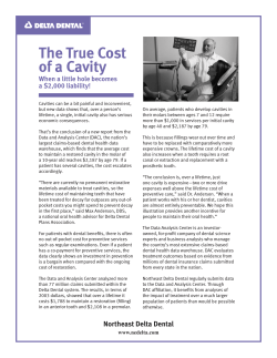
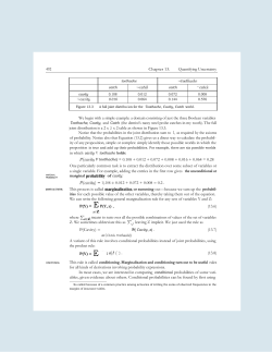
Proceedings of SRF2013, Paris, France
THP038
DEVELOPMENT AND PERFORMANCE OF A HIGH FIELD TE-MODE
SAMPLE HOST CAVITY∗
†
D.L.
Hall , M. Liepe, I. Madjarov, K. McDermott, N. Valles
Cornell Laboratory for Accelerator-based Sciences and Education, Ithaca, NY 14850, U.S.A.
Abstract
A TE-mode 4 GHz sample host cavity has been designed
and constructed at Cornell for the purpose of testing samples of niobium and other candidates for the construction
of SRF cavities. Simulations made using CLANS and
Omega3P indicate that when operating in the 4 GHz TE011
mode the peak magnetic field on the sample plate will reach
in excess 120 mT before a quench occurs on the surface of
the cavity due to thermal runaway. The cavity underwent a
first vertical performance test, achieving a peak field of the
sample plate of (40.4±4.0) mT. The cavity did not quench,
although RF drive resonances impeded operation at higher
fields. Once these are removed, the cavity will undergo further performance tests, after which it will be used in studies
of the superconductors Nb, Nb3 Sn and MgB2 .
Cornell has been developing TE-mode sample host cavities [1] for the purposes of studying the superconducting
RF properties of potential alternatives to niobium, such as
Nb3 Sn and MgB2 . To date, three cavities have been built,
shown in chronological order (left-to-right) in Fig 1. The
purpose of each cavity is to achieve the highest possible
peak magnetic field on the interchangeable sample plate
without causing a quench elsewhere in the cavity. Results
for the first generation “Pillbox” cavity and second generation “Mushroom” cavity are given in Refs. [2] and [3].
Both the Pillbox and Mushroom cavity operated at a resonant frequency of 6 GHz, with the Pillbox cavity achiev∗ Work supported by a NSF Career acount PHY-0841213 award to
Matthias Liepe
† [email protected]
Figure 2: The surface field distribution, as a ratio of the
peak surface field on the surface of the cavity, as calculated
by CLANS. Magnetic field lines are shown in black for
reference. The sample plate is located along the radial axis.
The diagram shows a 2D cross-section of half the cavity; to
obtain the 3D model, all points are rotated about the z-axis.
ing a peak sample plate field of 45 mT and the Mushroom
cavity reaching 60 mT. Both of these cavities were limited by thermal runaway quench at these fields. This was
later confirmed by thermal runaway simulations described
in Ref. [3].
This latest generation “Bulge/Onion/Bulb” (BOB) cavity was designed to operate at a lower frequency of 4 GHz
while maintaining the same sample plate size as the previous generation and a ratio of peak magnetic field on the
surface of the sample plate to that on the surface of cavity
walls of approximately unity. Simulations using CLANS
[4] and Omega3P [5] suggest that this latest generation
BOB cavity should be capable of reaching peak magnetic
fields in excess of 120 mT before a quench due to thermal
runaway on the cavity walls.
CAVITY DESIGN PROCESS
Figure 1: (A) Original pillbox cavity design (B) “Mushroom” cavity design (C) Latest “Bulge/Onion/Bulb”
(BOB) cavity design.
07 Cavity design
P. Cavity Design - Deflecting & other structures
The cavity was designed using an optimisation interface
written in MatLab that utilises CLANS for independent
field simulations. The optimisation is iterative; from an initial given set of geometrical parameters, the optimisation
software attempts of maximise the value of the expected
thermal runaway quench field (assuming a niobium sample
plate), Bquench , according to the relation
ISBN 978-3-95450-143-4
985
c 2013 by the respective authors
Copyright ○
INTRODUCTION
THP038
Proceedings of SRF2013, Paris, France
Bquench = B0
f0
f
2
R,
(1)
where f is the resonant frequency of the cavity, and R is
the ratio of the peak magnetic field on the sample plate to
the peak field on the cavity walls. The constants, B0 = 60
mT and f0 = 6 GHz, were obtained from thermal runaway
simulations conducted as part of previous TE cavity work
[3]. Simulations show that this latest model of TE sample
host cavity has R = 0.893 and Bquench = 123 mT when
operating in the TE011 mode at 3.954 GHz. The surface
field distribution and magnetic field pattern are shown in
Fig. 2.
The cavity was constructed from high-RRR niobium, using traditional fabrication methods. The cavity was diepressed in two separate parts, which were then welded together using electron beam welding. The cavity accepts
the same 5” diameter sample plates that were used for the
Mushroom cavity, as shown in Fig. 3. The circular area
of the sample plate exposed to the RF field inside the cavity has a diameter of 4”. The cavity also utilises the same
loop-style coupler developed at Cornell [6].
TEMPERATURE MAPPING SYSTEM
Cornell has previously developed a temperaturemapping (T-map) system for high resolution (≈0.2 mK)
temperature studies of superconducting niobium cavities
[7]. A new T-map system, based upon Cornell’s ILC
single-cell cavity T-map, has been constructed for use with
this latest sample plate cavity, upgrading the previous TE
cavity system from 6 sensors to 40, with the possibility of
upgrading to 56.
The temperature mapping system, shown in Fig. 4,
consists of a radial array of temperature sensors that are
mounted in direct contact with the sample plate, on the outside of the cavity. Each sensor is a resistor with a high
temperature coefficient in the <10 K region that, when
calibrated using a high-fidelity Cernox sensor, allows for
a measurement of the temperature difference between the
Figure 4: The new temperature mapping system built for
use with the BOB cavity. The design currently incorporates 40 sensors, with the possibility to upgrade to 56. The
system has a surface resistance resolution on the order of a
nΩ.
area covered by an individual resistor and the bath, ∆T .
From this, critical parameters such as surface resistance Rs
can be obtained as a function of location on the sample
plate to a spatial resolution of ≈ 1 cm and δRs ≈ 1 nΩ.
FIRST TEST RESULTS
The cavity was subjected to a vertical performance test
to measure quality factor as a function of peak field on the
sample plate surface. Prior to the test, the cavity received
a 100 µm EP, followed by a 700◦ C bake for 4 days and a
120◦ C bake for 48 hours. The TE011 mode was found at a
frequency of 3.949 GHz. The small deviation from the simulation value of 3.954 GHz is due to machining errors of up
to 0.8 mm in the upper half-cell of the cavity, as confirmed
by inspection with a coordinate measuring machine.
First test results were promising: the cavity achieved a
maximum field of (40.4 ± 4.0) mT on the sample plate
with a bath temperature of 1.5 K. No cavity quench was
observed during the test, although the maximum RF input
power was limited by drive line resonances. The cavity
quality factor as a function of the peak magnetic field on
the sample is shown in Fig. 5.
Throughout the test, drive line resonances impeded input
10
10
Q0
c 2013 by the respective authors
Copyright ○
1.5 K
9
10
20
25
30
35
40
45
50
Peak magnetic field on sample plate (mT)
Figure 3: Location of the 5” diameter sample plate on the
cavity, highlighted in red on the model.
ISBN 978-3-95450-143-4
986
Figure 5: Intrinsic cavity quality factor Q0 as a function of
the peak magnetic field on the surface of the sample plate.
07 Cavity design
P. Cavity Design - Deflecting & other structures
Proceedings of SRF2013, Paris, France
THP038
of more than 10 W into the cavity, and hindered effective
coupling. Furthermore, due to the necessity for strong coupling to the cavity imposed by these resonances, coupler
losses caused the measured quality factor to be artificially
lower than the expected Q0 ≈ 1 × 10¹⁰ .
CONCLUSION
The newly-commissioned BOB TE sample-host cavity
achieved a field of 40 mT on the sample surface during
its first test, limited only by the available input RF power.
This is a promising result for the future potential of the
cavity. Immediate efforts will focus on optimising the
RF drive system for 4 GHz higher-power operation, after
which the cavity will undergo further validation and performance tests with a niobium sample plate. The cavity will
then see use in high-field studies of MgB2 samples from
Los Alamos and Temple University, Pennsylvania.
REFERENCES
[1] Yi Xie and Matthias Liepe. “TE sample host cavities development at Cornell”. In Proc. of SRF 2011, Chicago, 2011.
[2] Yie Xie and Matthias Liepe. “First results on Cornell TE-type
sample host cavities”. In Proc. of IPAC 2012, New Orleans,
2012.
[3] Yi Xie. Development of superconducting RF sample host cavities and study of pit-induced cavity quench. PhD thesis, Cornell University, January 2013.
[4] D.G. Myakishev and V.P. Yakovlev. “The new possibilities of
SuperLANS code for evaluation of axisymmetric cavities”. In
Proc. of the Particle Accelerator Conference, 1995, volume 4,
pages 2348-2350. IEEE, 1995.
[5] Lie-Quan Lee, Zenghai Li, Cho Ng, and Kwok Ko.
“Omega3P: A parallel finite-element eigenmode analysis
code for accelerator cavities”. SLACPUB-13529, 2009.
[6] Yi Xie and Matthias Liepe. “Coupler design for a sample host
TE cavity”. In Proc. of SRF 2011, Chicago, 2011.
07 Cavity design
P. Cavity Design - Deflecting & other structures
ISBN 978-3-95450-143-4
987
c 2013 by the respective authors
Copyright ○
[7] Dan Gonnella, Sam Posen and Matthias Liepe. “Quench studies of a superconducting RF cavity”. In Proc. of IPAC 2012,
New Orleans, 2012.


© Copyright 2026