
Sampling & Sample Preparation For Quality Control
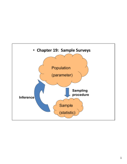
Sampling & Sample Preparation For Quality Control
Sampling:
M&W Jawo Handling provide samplers
either selected for our wide range of
standard samplers or specially designed
for client applications.
Sample preparation:
M&W Jawo Handling provide a full range of
equipment for sample preparation, this
includes several crushers and mills, sample
dividers, mixers as well as equipment for
sample transportation.
M&W JAWO Handling AS
1.
Representative Sampling Systems
2.
Samplers
3.
Dividers
4.
Dividing Plants
5.
Crushers
6.
Accessories
7.
Sampler Systems for Biomass
8.
Conveyors
9.
Questionnaire
10.
Sampling Theory
M&W
JAWO Handling AS
Oldenvej 5
3490 Kvistgaard
Tel.: +45 49139822
Fax: +45 49139162
[email protected]
www.m-w.dk
REPRESENTATIVE SAMPLING SYSTEMS
FOR
BULK MATERIALS
M&W JAWO HANDLING
T HE MARK & W EDELL SAMPLING SYSTEMS
TYPICAL SAMPLING SYSTEM
P ROCESS DIAGRAM
Knowledge of the properties of bulk material:
•
•
•
•
•
•
•
Content of prime property
Moisture content
Hardness
Content of minerals
Content of contamination
Size distribution
And many other properties
2
1
3
are essential when controlling the quality of the
material.
The properties are identified by taking statistically
representativ e samples from each batch of
material.
4
The Mark & Wedell Sampling System is an
integrated part of the control system available to the
operators.
The Sampling System provides the operator with
the means for executing the extraction and
preparation of representative samples of the
material.
5
The sample size is suitable for making laboratory
analysis.
6
The Mark & Wedell Sampling Systems operate in
accordance with approved international standards.
7
8
The results of the laboratory tests performed on the
basis of the representative samples prepared by
the sampling system are used for:
• Calculating the value or payment due for each
batch of material supplied.
• Adjusting down stream production.
• Calculating the amount of by-products from each
batch.
• Calculating the pollution from each
• Calculating the blending of various material
batches to obtain maximum end product.
9
10
DIAGRAM LEGEND:
1.Conveyor
7.Buffer container
2.Cross belt bucket sampler 8.Feeding belt
3.Feeding belt
9.Rotary tube divider
4.Chrusher
10.Sample bottles
5.Rotary tube divider
11.Reject material
6.Bias valve
conveyor
11
SAMPLING SCHEDULE:
In order to verify the material properties for a given material lot it is
necessary to take out a number u of sampling units. This number
depends on the mass of the lot and on the desired overall
sampling precision. Minimum requirements are listed in Table 1.
Each sampling unit is taken by the sampling equipment as n
increments, where n should be 10 or more.
Mass of Lot
tonnes
< 5.000
5.001 – 20.000
20.001 – 45.000
45.001 – 80.000
80.001 – 125.000
125.001 – 180.000
180.001 – 245.000
No. of sampling
units
1
2
3
4
5
6
7
The properties of the materal lot can be determined with an overall
precision PL using equation 1 where:
• VPT is variance of sample preparation and test. If no data
available: assume 0.2
• VI is the variance of primary increment. If no data available:
assume 20
The overall precision is a function of the number of sampling units
u, the variance of sample preparation and test VPT, the number of
increments n and the variance of the increments VI.
If a given precision PL is required the number of increments n and
the number of sampling units u can be found using Equation 2 and
3 respectively.
TABLE 1
PL
VI
= ±2 n
+ VPT
u
EQUATION 1
n =
4VI
− 4VPT
2
L
uP
EQUATION 2
u =
The values n and u are adjusted upwards and recalculated to a
convenient combination respecting the required minimum values.
4VI
+ 4n1VPT
n1PL2
EQUATION 3
EQUIPMENT SIZING CONSIDERATIONS:
The mass of each primary increment can be calculated using
Equation 4 where:
• C is flow rate [t/h] on conveyor belt.
• A is cutting aperture [mm].
Should be / 3 times the nominal top size of material.
• S is cutter speed [m/s].
If S is constant the incremental mass is a function of the flow rate
C, the nominal top size of the lumps and cutting aperture A.
As a guideline for lay-out of sampling systems the reference
increment mass from Table 2 should be used as minimum values.
The total mass of the sample (sampling unit) is at least n times the
increment mass where n is at least 10 as previously discussed.
SAMPLE DIVISION:
To obtain convenient sample masses, the sample is divided into a
number of statistically identical but smaller samples and a rest
which is returned to the conveyor.
From the preceeding section is seen, that reducing the mass
needs a reduction in particle size is required in order to preserve
the representative nature of the sample. For this reason a system
for extraction of representative samples of materials consists of
multistage extraction, particle reduction and division equipment.
m =
C ⋅ A
⋅ 10 −3 [kg ]
3,6 ⋅ S
EQUATION 4
Nominal top size
mm
300
200
150
125
90
63
45
31,5
22,4
16,0
11,2
8,0
Reference incr.
Mass
Kg
100
25
15
10
5
3
2
1
0,75
0,50
0,25
0,15
TABLE 2
The Company and its product line
M&W is an internationally working
engineering company specialized in the
design, manufacturing and supply of
sampling systems for all type of bulk
materials for quality control, optimising
processes and controlling by-products in
installations world-wide.
M&W ’s product line
•
•
•
•
•
•
Sampling Systems
Modular Sampling Systems
Samplers
Dividers
Crushers
Accessories
Member of the Mark & Wedell Group - Oldenvej 5, DK-3490 Kvistgaard, Denmark
Tel.: +45 49 13 98 22 Fax:+45 49 13 91 62 - Internet: www.m-w.dk E-mail: [email protected]
CROSS BELT HAMMER SAMPLER
TYPE HP
The Cross Belt Hammer Sampler suits the purpose of taking representative samples of
granular material being conveyed on a belt conveyor. Representability of the sample is
ensured by taking a complete cross section of the material on the conveyor belt.
The Hammer Sampler is suited for granulated material, and offers high flexibility in place
of installation anywhere along the conveyor belt.
The Hammer Sampler principle is compatible with all internationally applicable standards
for sampling.
Basic Functionality
The cutting device is the hollow head of the hammer. When a sample is taken the
hammer sweeps one revolution across the conveyor whereby the hammerhead cuts
through the material stream on the belt. The sample is thereby captured by the hollow
hammerhead, which in turn is emtied over the sample outlet.
The hammer is actuated by an electric motor with integrated brake designed to
accelerate and decelerate the hammer and return it to its parking position safely away
from the material stream.
To reduce the dynamic effects on the supports, the hammer is forseen with
counterweights.
The hammer samplers rotation is controlled by an electronic control unit.
M&W JAWO HANDLING
The nominal size of the hammer sampler is chosen corresponding to the width of the
conveyor belt, so the HP1200 is for use on a 1200mm wide conveyor belt.
Cross Belt Hammer Sampler:
A (mm)
B (mm)
C (mm)
HP 500
HP 650
HP 800
HP 1000
HP 1200
HP 1400
HP 1600
HP 1800
HP 2000
HP 2200
1300
1500
1750
2050
2350
2650
2950
3250
3550
3850
950
1150
1350
1600
1850
2150
2400
2650
2900
3150
1800-2450
1950-2650
2150-2800
2350-3000
2550-3250
2750-3450
2950-3650
3150-3900
3350-4100
3550-4300
The dimension in the direction along the conveyor belt, depends on the specific project
data for particle size, cut size, and motor type.
Member of the Mark & Wedell Group - Oldenvej 5, DK-3490 Kvistgaard, Denmark
Tel.: +45 49 13 98 22 Fax:+45 49 13 91 62 - Internet: www.m-w.dk E-mail: [email protected]
CROSS BELT BUCKET SAMPLER
TYPE CBBS
The Bucket Sampler Type CBBS is designed to take out a representative sample of powdered
material and lumps up to 100 mm, from a free falling flow of materials.
General Description:
The Bucket Sampler Type CBBS consists of a cutter attached to a carriage running on a double
rail system. The carriage is driven by an electric motor via two roller chains.
The cutter is individually selected based on layout conditions, size of sample and maximum
particle size. An additional supporting beam with rail can be added, depending on cutter design.
The sampling can be based on tangential or vertical vectors of the material flow and the degree
of admission is chosen so that overloading does not occur while the cutter passes through the
material flow. The cutter is available in S235 JRG2 or stainless steel depending on the material
to be sampled.
The cutter is mechanically opened/closed outside the material flow for sample discharge into a
hopper. The resting position of the cutter between two samples is outside the material flow.
M&W JAWO HANDLING
A
850
B
SAMPLER TYPE
CBBS 500
CBBS 650
CBBS 800
CBBS 1000
CBBS 1200
CBBS 1400
CBBS 1600
A:
Total length
mm
2500
2650
2800
3000
3200
3400
3600
B:
Travel distance
mm
1700
1850
2000
2200
2400
2600
2800
Weight
Kg
220
229
238
250
262
275
286
The cutter is individually designed based on layout conditions, particle size, required
sample size, etc.
Cutter Type:
Slot width: (SP)
Speed: (V)
Net. volume: (N)
ST (tangential)
3 x max particle size
Max 0.8 m/sec
SL (vertical)
3 x max particle size
Max 0.8 m/sec
N=Q*SP*X
3.6*V
N=Q*SP*X
3.6*V
where N is cutter volume in litres, Q is material flow in m3/h, SP is slot width in m
and V, is cutter speed in m/s.
Member of the Mark & Wedell Group - Oldenvej 5, DK-3490 Kvistgaard, Denmark
Tel.: +45 49 13 98 22 Fax:+45 49 13 91 62 - Internet: www.m-w.dk E-mail: [email protected]
CHUTE SAMPLER
TYPE FP
The Chute Sampler Type FP is designed to take out increments of none-sticky powdered
material and lumps up to 40 mm, in a closed pipe system, from a free falling flow of materials.
General Description:
The sampler is driven by a geared motor and toothed V-belt drive. A specially designed cutter
rotates around a vertical axis. The cutter inlet is designed so that the full cross section of the
material flow is cut through during one rotation, and further is shaped so that all particles from
any part of the cross section have the same probability of being sampled i.e.: a representative
sample is taken. The sample is extracted into a chute where a tight fitting sample bottle can be
mounted, or it falls by gravity in a chute to further sample preparation.
An inspection hatch is provided on top of the sampler body.
The sampler cutter is parked well away from the material stream, when no sample is taken.
The cutter is available in stainless steel or wear resistant material. The body is manufactured
from mild steel plate.
The control of the sampler is normally conducted from a local control system, which can be
connected to a central PLC-system.
M&W JAWO HANDLING
The sampler can be mounted in a vertical chute, either circular or rectangular.
Drive:
Type:
Voltage:
Type:
FP
FP
FP
FP
100
200
300
500
Helical geared motor and toothed V-belt drive
3 x 400 V, 50 Hz
Particle
Size
mm
Max. 10
Max. 15
Max. 25
Max. 40
A
mm
B
mm
C
mm
Do
mm
ø/? 100
ø/? 200
ø/? 300
ø/? 500
800
1050
1310
1790
600
800
900
1200
ø 470
ø 720
ø 940
ø 1420
Motor Speed
kW
m/s
0.25
0.25
0.37
0.55
0.6
0.6
0.6
0.6
Wgt
kg
55
80
120
140
Member of the Mark & Wedell Group - Oldenvej 5, DK-3490 Kvistgaard, Denmark
Tel.: +45 49 13 98 22 Fax:+45 49 13 91 62 - Internet: www.m-w.dk E-mail: [email protected]
CHUTE SAMPLER
TYPE FPMX
The Chute Sampler Type FPMX is designed to take
out increments of non-sticky powdered material and
lumps up to 40 mm, in a closed pipe system, from a
free falling flow of materials and collecting these in a
mixing tank for establishment of mean samples.
General Description:
The sampler is driven by a geared motor and toothed
V-belt drive. A specially designed spoon rotates
around a vertical axis. The spoon inlet is designed so
that the full cross section of the material flow is cut
through during one rotation, and is further shaped so
that all particles from any part of the cross section
have the same probability of being sampled i.e.: a
representative sample is taken. The samples are
collected in a mixing tank, where they are
homogenized.
Samples can be discharged manually or automatically
from the mixing tank.
By manual discharging, the mixed sample is collected
in a beaker (approximate volume 1.4 litres) and
afterwards the mixing tank is emptied through a
manually operated bottom gate.
By automatic discharging, a hydraulic operated
bottom gate empties the mixer tank into a chute
where additional equipment like dosing unit and
automatic tube post receiving/sending station can be
installed for further handling of the samples.
This system design ensures, that the material at any time present in the mixer tank will represent
a true and representative average of the material having passed the sampler, since last emptying
of the mixer tank.
An inspection hatch is provided on top of the chute sampler body.
The sampling spoon is parked well away from the material stream, when no sample is taken.
The spoon is available in stainless steel or wear resistant material. The body is manufactured
from mild steel plate.
The control of the sampler and hydraulic operated bottom gate is normally operated from a
central PLC-system.
M&W JAWO HANDLING
The sampler can be mounted in a vertical chute, either circular or rectangular.
Drive:
Sampler:
Mixer:
Outlet mixer:
Voltage:
Type:
FP 100
FP 200
FP 300
FP 500
Type: Helical geared motor and toothed V-belt drive.
Type: 0.55 kW geared motor, 4 pole, 36 rpm.
Type: Hydraulic actuator.
3 x 400 V, 50 Hz.
Particle
size mm.
Max. 10
Max. 15
Max. 25
Max. 40
A
mm
Ø/! 100
Ø/! 200
Ø/! 300
Ø/! 500
B
mm
800
1050
1310
1790
C
mm
600
800
900
1200
D0
mm
ø 470
ø 720
ø 940
ø 1420
Motor
kW
0.25
0.25
0.37
0.55
Speed
m/s
0.6
0.6
0.6
0.6
Wgt
m/s
55
80
120
140
Member of the Mark & Wedell Group - Oldenvej 5, DK-3490 Kvistgaard, Denmark
Tel.: +45 49 13 98 22 Fax:+45 49 13 91 62 - Internet: www.m-w.dk E-mail: [email protected]
Screw Sampler
Type SMX
SMX with automatic discharge
Optionally: SMX made of stainless steel
The Screw Sampler Type SMX is designed to create an average sample from continuous
extraction of dry, non-sticky powdered material from a free falling flow of materials.
General Description:
The continuously operating sampler is driven by a geared motor, coupled to a transport screw
crossing the flow of material. The screw transports the extracted material to a mixing tank, where
it is homogenized by mixer wings connected to the through going screw conveyor shaft. The
sampler can be delivered with the drive unit installed next to the mixing tank (Type SMX-A500RM) or for installation on the opposite side of the chute (Type SMX-A500R-S).
The mixed test sample is extracted manually (SMX-M500R-M) from the mixing tank into a beaker
(volume approx. 1.4 litres) and the mixing tank content is manually discharged afterwards.
This mixer design ensures, that the material at any time present in the mixer tank will represent a
true average of the material having passed the sampler, since the mixing tank was last emptied.
The mixing tank is provided with an observation window and has an overflow to safeguard
against overfilling. Excess sample material is returned to the main material stream by gravity.
The standard SMX sampler is not suited for installation in pressure systems.
As an option the screw sampler can be provided with a pneumatic cylinder for automatic
discharge (SMX-A500R-M) of the mixer tank content into the reject chute, where optional
equipment like dosing unit for automatic tube post sending/receiving station can be installed.
For special purposes the SMX sampler can be provided with variable speed drive.
M&W JAWO HANDLING
A
~1110
~690
560
132
235
max.30E
E
The SMX sampler can be mounted in a chute with max. 30º inclination, either rectangular or
circular.
Standard outside chute dimensions:
A = 250, 315, 355, 400, 450, 500, 560, 630 or 710 mm.
Main dimensions:
Total length:
A + 1245 mm
Screw diameter:
ø 50 mm
Mixing tank volume:
~ 25 l (effective)
Flange, outlet mixing tank:
280 x 280 mm
Weight:
App. 90 kg
Drive:
Type:
Helical geared motor
Voltage:
3 x 400 V, 50 Hz
Power:
0.18 kW
Speed:
10 rpm
Coupling:
Elasto rotative
Pneumatics: (for automatic discharging only).
Type:
Double acting cylinder
Pressure:
Min. 5 bar, max. 10 bar
Quality:
Dry and oil free
Consumption:
Minimal
Signal:
Type:
REED-Switch
Voltage:
AC: Max. 240 V, max. 50 VA, max. 5000 mA
DC: Max. 300 V, max. 50 W
Member of the Mark & Wedell Group - Oldenvej 5, DK-3490 Kvistgaard, Denmark
Tel.: +45 49 13 98 22 Fax:+45 49 13 91 62 - Internet: www.m-w.dk E-mail: [email protected]
SCREW SAMPLER
TYPE SCR
Screw Sampler Type SCR
The Screw Sampler Type SCR is designed for sample extraction of dry, non-sticky powdered
material from a free falling flow of materials.
General Description:
The sampler is driven by a geared motor coupled to a transport screw, crossing the flow of
material. The screw transports the extracted material to a discharge outlet chute where the
material falls by gravity to the subsequent sample preparation equipment.
The screw sampler is equipped with an inductive motion detector.
The screw sampler type designation is based on chute dimension in mm as well as chute form.
The screw sampler can be mounted in chutes (rectangular SCR-XXXR or circular SCR-XXXC)
with maximum inclination of 30º.
The control of the sampler is normally conducted from a central PLC system.
As an option, the screw sampler can be equipped with variable speed geared motor.
M&W JAWO HANDLING
The Company and its product line
M&W is an internationally working
engineering company specialized in the
design, manufacturing and supply of
sampling systems for all type of bulk
materials for quality control, optimising
processes and controlling by-products in
installations world-wide.
M&W ’s product line
•
•
•
•
•
•
Sampling Systems
Modular Sampling Systems
Samplers
Dividers
Crushers
Accessories
Member of the Mark & Wedell Group - Oldenvej 5, DK-3490 Kvistgaard, Denmark
Tel.: +45 49 13 98 22 Fax:+45 49 13 91 62 - Internet: www.m-w.dk E-mail: [email protected]
AIR SLIDE SAMPLER
TYPE AS
M&W Jawo Handling
The Air Slide Sampler Type AS is designed for continuous or intermittent sample
extraction of dry, non-sticky powdered material flowing in air slides.
The AS sampler can be installed in any existing air slide within a couple of hours.
General Description:
The AS sampler has a rotating tube provided with a 4 mm longitudinal slot. The tube is
fastened in the hollow axle gear in that way the extracted sample will fall directly into the
sample bottle.
By intermittent sample extraction the rotating tube is parked between the sampling
period, with the slot into the protective guard (opposite the material flow).
The AS sampler is provided with an inductive sensor acting as combined speed monitor
and position indicator.
The AS sampler is manufactured from stainless steel AISI 304.
The AS sampler is designed for working in a non-condensed environment.
M&W JAWO HANDLING
Principle Sketch:
Air Slide
Sample Container
Drive:
Type:
Voltage:
Power:
Speed:
Sampler Type
A (mm)
B (mm)
AS 200/400
AS 400/600
AS 600/800
200 – 315
315 – 350
350 – 450
To be informed by the client!
To be informed by the client!
To be informed by the client!
Worm geared motor with brake.
3 x 400 / 230 V, 50 Hz
0.25 kW
192 rpm
Extraction Capacity:
Approximately 1 litre/minute at 500 t/h air slide capacity and continuous operation,
however, subject to material velocity and degree of filling.
Member of the Mark & Wedell Group - Oldenvej 5, DK-3490 Kvistgaard, Denmark
Tel.: +45 49 13 98 22 Fax:+45 49 13 91 62 - Internet: www.m-w.dk E-mail: [email protected]
PSS 2200
Powder Sampling System
AUTOMATIZING QUALITY ASSURANCE FOR POWDERS
M&W JAWO HANDLING
Functionality and application fields for PSS 2200
The PSS 2200 automatizes sampling and registration of
samples for powders. As such the PSS forms part of a quality
assurance system for powders conveyed pneumatically in
closed piping. Obvious sites for installation are at silo outlets
or in the pipes for loading or unloading from powder transport
vehicles where the powder changes hands.
1. Identification
The transporter checks in to the system using a magnetic
card. The card reader is located besides the control panel.
The system also read the identity barcode of the sample
bottle to be used for the representative sample.
2. Sampling
From the probe mounted in the transport pipe a side stream
is conducted to the sample preparation section of the PSS.
Here the individual sample increments, cuts, are measured
and stored in the sample container. Cutting is done on a time
basis.
3. Registration
The combination of data for transporter ID, sample bottle ID,
sampling period and number of sample increments are sent
to the plant quality registration computer database for
combination with other relevant data.
When the next transporter checks in, the system will select
the next available sampling bottle.
Media
Dry, nonsticky non-food powder. Extraction is possible from
pneumatic transport lines or from silos/hoppers. Handles
powders of flyash, cement, limestone.
Operating conditions
Temperature: < 80°C. Dewpoint < 45°C
Pressure < 3bar/43psi (5bar/70psi in transients)
Particle size ø1mm (Nominal top size)
Sampling strings:
Number of sample strings: 5
Sample increment (cut): 100cm3 or 200 cm3
Sample bottle volume: 2500 cm3
Advantages of PSS 2200
▪ Secure link between transporter ID and sample ID
▪ Transfer of data to quality registration database
▪ Automatic sampling
▪ Require a minimum of manual attention
▪ Proven sampling technology
System unit
Stainless Steel enclosure with IP57 rating. Control panel is
protected with transparent dust and watertight cover.
Power supply: 230V/50Hz or 115V/60Hz
Connection to compressed instrument air 6bar/ 70psi.
Overall size (WxHxD): 240cmx220cmx60cm
Weight: 450 kg
Member of the Mark & Wedell Group - Oldenvej 5, DK-3490 Kvistgaard, Denmark
Tel.: +45 49 13 98 22 Fax:+45 49 13 91 62 - Internet: www.m-w.dk E-mail: [email protected]
ROTARY TUBE DIVIDER
TYPE PD
Rotary Tube Divider Type PD-12/100-1
The Rotary Tube Divider is used for dividing samples of bulk materials. The main advantage of
mechanical sample dividers is that, they extract a part of the material by a large number of
increments. If, less than about, 50 increments are taken by the sample divider, the accuracy may
be substantially reduced. A continuous automatic sample division ensures, that the divided
sample is still a representative sample.
General Description:
The dividing tube is rotated by the drive unit. The material is charged through the dividing tube,
which passes respectively extractor and discharge cone. The division ratio is step less
adjustable.
Depending upon model size, it is possible to divide materials up to a particle size of ø65 mm.
Dividing ratio = slot opening/(division circumference – slot opening)
The Rotary Tube Divider consists essentially of following units:
• Drive unit (gear motor and belt)
• Dividing Tube of stainless steel
• Top cone with inspection/cleaning opening
• Stainless steel discharge cone with reject outlet and one or more sample outlets
M&W JAWO HANDLING
C
DO
A
dR
dS
E
Drive:
Voltage:
Helical geared motor
V-belt drive
3 x 400 V, 50 Hz
Type
Max part.
size mm.
øA
mm
B
Mm
C
mm
øDo
mm
ds
mm
ødR
mm
E
mm
Motor
kW
PD 8/50
PD 8/100
PD 12/100
PD 12/200
PD 17/100
PD 17/200
PD 27/100
PD 27/200
15
25
35
40
35
50
35
65
50
100
100
200
100
200
100
200
515
535
810
810
1035
1035
1515
1515
625
625
925
925
925
925
925
925
410
410
640
640
740
740
1110
1110
60x60
60x60
60x60
150x150
60x60
150x150
100x100
150x150
100
100
200
200
200
200
200
200
170
170
260
260
330
330
600
600
0.25
0.25
0.25
0.25
0.37
0.37
0.55
0.55
Div.
Circ.
mm
825
825
1255
1255
1720
1720
2700
2700
Tube
rpm
Wgt
kg
44
44
29
29
21
21
13
13
50
55
70
80
120
130
170
175
Member of the Mark & Wedell Group - Oldenvej 5, DK-3490 Kvistgaard, Denmark
Tel.: +45 49 13 98 22 Fax:+45 49 13 91 62 - Internet: www.m-w.dk E-mail: [email protected]
DISC DIVIDER
TYPE DD
The Disc Divider is used for dividing samples of powder and bulk materials (even
suitable for wet materials). The main advantage of mechanical sample dividers is that
they extract a part of the material by a large number of increments. If less than about 50
increments are taken by the sample divider, the accuracy may be substantially reduced.
A continuous automatic sample division ensures that the divided sample is still a
representative sample.
General Description:
The sample has to be delivered on the top cone of the Disc Divider. The sample will be
scraped from the upper disc to the lower disc, where it will be scraped to the bottom
cone, where a part will go through the sample outlet(s) and the rest will fall through the
bottom cone as reject.
The division ratio is step-less adjustable between 1:9 and 1:59 – Depending on particle
size and upon model size. It is possible to divide materials up to a particle size of ø65
mm.
The Disc Divider consists essentially of the following units:
• Drive unit (gear motor).
• Upper and lower discs with scrapers.
• Upper part with inspection/cleaning openings.
• Lower part with reject outlet and one or more sample outlets.
M&W JAWO HANDLING
Principle Sketch:
Member of the Mark & Wedell Group - Oldenvej 5, DK-3490 Kvistgaard, Denmark
Tel.: +45 49 13 98 22 Fax:+45 49 13 91 62 - Internet: www.m-w.dk E-mail: [email protected]
RIFFLE DIVIDER
TYPE RF
The Riffle Divider Type RF is designed for manual representative dividing of dry, granulated and
powdered sample material.
General Description:
The Riffle Dividers, type RF are used for the easy dividing and reduction of bulk material samples
with particle sizes ranging from less than 1 mm up to a maximum of 10 mm. After a
representative sample extraction has been effected, further reduction is the major prerequisite for
exact analysis results in accordance with the characteristics of the bulk quantity. Due to its
special sampling method, the Riffle Dividers provide an accuracy which is superior to all other
manual procedures. Higher accuracy can only be obtained with mechanical dividers such as the
rotary tube divider Type PD.
The sample material cascades into the two collecting receptacles through a number of slots,
which are arranged opposite to each other. With each dividing process, the feed quantity is
halved until the required sample quantity has been reached.
Riffle dividers are particularly suitable for field use since they can be operated independent of
electrical or mechanical energy sources.
The appropriate type of Riffle Dividers is selected according to existing standards and
regulations, if available, and the maximum particle size which determines the required width of
the slots in the dividing head. Depending on material, maximum particle size and mass
percentage thereof, the slot opening shall be 1.5 to 3.5 times the diameter of the largest particle.
Features and advantages:
• Quick, simple dividing even with difficult bulk materials
• Each dividing process will halve the feed sample quantity
• Almost any sample quantity can be obtained with repeated dividing
• Wide application range in the field or in laboratory
• Operates independently of mechanical or electrical supply sources
• Easy cleaning and no maintenance required (no moving parts)
• Most accurate method of manual dividing
M&W JAWO HANDLING
Riffle Divider
Type
RF 12/10
RF 15/12
RF 20/16
RF 30/16
Number
of
cells
10
12
16
16
Particle size
In mm
<4
<5
<7
<10
Slot width
(A)
in mm
12
15
20
30
Container
volume
in dm3
2
4
8
15
Weight
in kgs
5
7.5
27
34
Member of the Mark & Wedell Group - Oldenvej 5, DK-3490 Kvistgaard, Denmark
Tel.: +45 49 13 98 22 Fax:+45 49 13 91 62 - Internet: www.m-w.dk E-mail: [email protected]
ROTARY TUBE DIVIDING PLANT
The Rotary Tube Dividing Plant is
used for representative subdivision of
material. The dividing plant can be
provided with one or more sample
outlets. The plant can be installed in
conjunction with a sampling plant or
placed completely independent of the
sampling operation.
General Description:
The material is extracted from the feed
hopper by a stepless adjustable
vibration feeder and dosed into the
rotary tube divider. The material is led
by gravity through the dividing tube,
which passes respectively extractor and
discharge cone. The division ratio is
stepless adjustable.
Division ratio = slot opening: (Division circumference – slot opening)
The sub-divided material is collected in a dust-proof sample bottle, and the rejects are collected
in a plastic container.
The components are installed in a lightweight corrotion protected steel structure.
The rotary tube dividing plant is available for bulk materials up to 65 mm dia lumps.
The Rotary Tube Divider consists essentially of following units:
•
•
•
•
•
•
•
Feed hopper
Vibration feeder
Rotary Tube Divider, Type PD
Supporting steel structure
Electrical control box with feeder – and vibration control, 230/400 V, 50 Hz
Sample bottle
Reject container
M&W JAWO HANDLING
B
C
Drive:
Helical geared motor
V-belt drive
Voltage:
3 x 400 V, 50 Hz
Plant
Type
PD8P
PD12P
PD17P
PD27P
Feed
hopper
Ltr
15
25
50
75
Vibration
Feeder
Tube
Divider
A
mm
B
mm
C
mm
Weight
kg
50 w
200 w
200 w
500 w
PD8
PD12
PD17
PD27
1500
1800
2200
2600
730
960
1060
1430
980
1200
1600
2200
125
167
245
330
Member of the Mark & Wedell Group - Oldenvej 5, DK-3490 Kvistgaard, Denmark
Tel.: +45 49 13 98 22 Fax:+45 49 13 91 62 - Internet: www.m-w.dk E-mail: [email protected]
MOBILE DIVIDING PLANT
The Dividing Plant is used for representative division of material. The Divider can be
provided with up to 20 sample outlets. The Dividing Plant can be installed in conjunction
with a sampling plant or placed completely independent of the sampling operation.
General Description:
The material is extracted from the feed-hopper by a step-less adjustable vibration feeder
and dosed into the Rotary Tube divider. The material is led by gravity through the
dividing tube, which passes the respectively sample outlets in the under cone.
The divided samples are collected in dust-proof sample containers.
The Dividing plant is available for dry powder and bulk materials with corn size up to 15
mm.
The Dividing Plant consists essentially of following units:
* Feed hopper
* Vibration feeder
* Rotary Tube Divider, type PD (with special under cone).
* Supporting steel structure (on wheels) and stair.
* Electrical control box with feeder- and vibration control, 230/400 V, 50 Hz.
* Sample containers.
The Dividing Plant is manufactured from glass blasted stainless steel (EN .1.4401 / EN
1.4301).The AS sampler can be installed in any existing air slide within a couple of
hours.
M&W JAWO HANDLING
Principle Sketch:
Plant type:
PD08 MP
PD12 MP
Drive:
Feed
Hopper
Ltr.
40 (net)
80 (net)
Rotary
Tube
Divider
PD08
PD12
Sample
Container
Ltr.
Max 2 (net)
Max 4 (net)
Sample
Container
Pc.
Max 20
Max 20
A
mm
B
mm
C
mm
1900
2050
1200
1500
800
800
Vibration Feeder:
0.2 kW magnet
Rotary Tube Divider: 0.25 kW helical geared motor / V-belt drive
Voltage: 230 / 400 V, 50 Hz
Member of the Mark & Wedell Group - Oldenvej 5, DK-3490 Kvistgaard, Denmark
Tel.: +45 49 13 98 22 Fax:+45 49 13 91 62 - Internet: www.m-w.dk E-mail: [email protected]
Spinning Riffle Divider Plant
Type SRD
The Spinning Riffle Dividing Plant is used for representative division of material. The
Divider can be provided with up to 16 sample pans. The Dividing Plant can be installed in
conjunction with a sampling plant or placed completely independent of the sampling
operation.
General Description:
The material is extracted from the feed-hopper by a step-less adjustable vibration feeder
and dosed into the Sample containers, placed on the spinning table. The material is led
by gravity into the sample containers. The spinning table with the sample containers
rotates constantly, with 12 rpm.
The feed rate is adjustable by variable amplitude 200 watt vibration feeder and by the
positioning of the exit gate in the hopper. The gate is adjustable from 0 – 150 mm.
The divided samples are collected in sample containers. Each container has an
overlapping deflector lip on one side to form cutting edges and prevent loss of fines.
The Dividing plant is available for powder and bulk materials with up to 50 mm corn size.
The Dividing Plant consists essentially of following units:
•
•
•
•
•
•
•
Feed hopper ~50 litre.
Vibration feeder.
Spinning table for sample containers.
Supporting steel structure.
Safety guard around the spinning table. With doors for emptying the
sample containers.
Electrical control box with feeder- and vibration control, 230/400 V,
50 Hz.
8 Sample containers ~7 litre each (standard).
All parts of the Dividing Plant are manufactured from stainless steel (en 1.4301 / EN
1.4401), except the steel structure, which is painted mild steel.
Options:
- The divider can be provided with a knocker on the feed hopper, used e.g. by
moist material.
- Sets of 4, 6, 12 and 16 sample containers according to customer requirements.
M&W JAWO HANDLING
Principle Sketch:
Drive:
Vibration Feeder:
Divider:
Voltage:
230 / 400 V, 50 Hz
0.2 kW electro magnet
0.25 kW helical geared motor / V-belt drive
Member of the Mark & Wedell Group - Oldenvej 5, DK-3490 Kvistgaard, Denmark
Tel.: +45 49 13 98 22 Fax:+45 49 13 91 62 - Internet: www.m-w.dk E-mail: [email protected]
!"#$"
!
"
""
#
$
%&
$$
$
$
&
&
$
&
&&
$
'
#
&
$
&
&
&
%&"''&
%()*+),-+./0#.1
%
=>
(=>
=>
73
7<
4
4
98
<8
%
%"()1
,&/!234!&/"
5633424788'563342498#5$$$$":5$;$"
CONTAINERS
(CONTAINERS,
BUCKETS, BARRELS ETC.)
M&W Jawo Handling AS
offers a wide range of highquality process containers
for the pharmaceutical, food
and chemical industries.
Containers and accessories
will be customised for
specific use.
Barrels:
Standard barrels with open top from 25 to 500 litres, complete with cover and clips in all
sizes in EN 1.4301 or EN 1.4401 stainless/acid-proof steel or other qualities when
required. Surface finish as required.
Cone Outlets and Funnels:
Symmetrical and asymmetrical cones customised for any use.
Standard slip angle of 60 degrees, other angles as required.
Internal Transport containers:
M&W Jawo Handling offers transportation for dry product processes for volumes ranging
from 1 to 2,500 litres.
Material and surface finish as required.
For instance in pallet size for transportation by means of pallet lifts or fork trucks.
Accessories:
M&W Jawo Handling offers a wide range of accessories, including:
- Valves
- Outlet Vibrators
- Flow Regulators
- Wheels mounted directly on containers or as container trolleys
- Dust-proof Couplings to/from container.
Technical Data:
Stainless/acid-proof steel: EN 1.4301, EN1.4401
Welding:
TIG
Crack and crevice free
Finish:
2B cold-rolled
Sanded according to required grit size
Electro polished
Glass-bead blasted
Member of the Mark & Wedell Group - Oldenvej 5, DK-3490 Kvistgaard, Denmark
Tel.: +45 49 13 98 22 Fax:+45 49 13 91 62 - Internet: www.m-w.dk E-mail: [email protected]
SAMPLE COLLECTOR
TYPE PK / PKT
Sample Collector, type PK-10/8
Sample Collector, type PKT-1/17
The Sample Collector is designed for automatic loading of powder and fine granulates into
sample bottles in numbers from 6 to 26 and in sizes from 250 ml to 20 l.
General Description
The Sample Collector consists of the following parts:
•
•
•
•
•
•
A turn table with positioning disc for 26 to 6 sample bottles in size from 250 ml to 20 l.
The turn table shaft is provided with an index disc with 6 to 26 pitches.
The turn table is driven via a secondary disc with a ratchet tooth which engage with the
index disc during rotation. The secondary disc is directly connected to a geared motor in
such a way that one rotation of the secondary disc corresponds to one step on the turn table
bringing the next sample bottle in position for filling.
For exact positioning of the turn table a pneumatic operated locking ratchet will engage with
the index disc and secure the position.
Before filling takes place a pneumatic operated telescopic filling tube will be extended to
engage with the sample bottle in a dust tight connection.
Removal of filled sample bottles takes place manually through an access door in the upper
part of the cabinet. The access door is provided with a safety switch which allows rotating
the turn table by hand for accessing all sample bottles on the turn table.
M&W JAWO HANDLING
As an option the Sample Collector can be provided with spring loaded tightening devices on all
sample bottles (type PKT) ensuring constantly sealed sample bottles.
Sample Collector
Type
Bottle
Volume
Bottle
Quantity
Cabinet
Width
[mm]
Cabinet
Depth
[mm]
Cabinet
Height
[mm]
Opened
Height
[mm]
PK-0,25/26
250 ml
26
904
904
667
1006
PK-0,5/22
500 ml
22
904
904
701
1040
PK-0,75/19
750 ml
19
904
904
720
1059
1l
17
904
904
752
1091
1,5 l
15
904
904
773
1112
PK-2/13
2l
13
904
904
794
1133
PK-5/9
5l
9
904
904
882
1221
PK-10/6
10 l
6
904
904
962
1301
PK-10/8
10 l
8
1166
1166
650
1000
PK-20/6
20 l
6
1166
1166
950
1300
PK-1/17
PK-1,5/15
The Company and its product line
M&W is an internationally working
engineering company specialized in the
design, manufacturing and supply of
sampling systems for all type of bulk
materials for quality control, optimising
processes and controlling by-products in
installations world-wide.
M&W ’s product line
•
•
•
•
•
•
Sampling Systems
Modular Sampling Systems
Samplers
Dividers
Crushers
Accessories
Member of the Mark & Wedell Group - Oldenvej 5, DK-3490 Kvistgaard, Denmark
Tel.: +45 49 13 98 22 Fax:+45 49 13 91 62 - Internet: www.m-w.dk E-mail: [email protected]
Dosing Unit
Type DU
Automatizing Cement Plant Sample Logistics
The Dosing Unit Type DU is designed to provide the link between the sampler and an
automatized system for sample transport. The Dosing Unit collects a sample from the
mixer outlet of a SMX-A sampler into a cartridge in a pneumatic tube system forwarding
the sample to the laboratory.
The Dosing Unit sits in a vertical or suitably
inclined duct under the mixer outlet.
While the mixer outlet is opened, a sample
drawer is inserted into the stream of material to
be filled.
When the drawer is retracted from the stream,
the powder is released to the sending station.
The Dosing Unit Type DU is compatible with a
wide range of samplers and homogenizers and
mixers and has been used with:
•
•
•
•
•
SMX type Screw Sampler
SMX-A type Automatic Screw Sampler
AS type Air Slide Sampler
M-R type Radial mixer
M-K type Cone mixer
M&W JAWO HANDLING
Dimensions:
Nom. volume
D
d
A
L
DU200
200ccm
ø131mm
ø55mm
ø80mm
550mm
DU500
500ccm
ø180mm
ø76.1mm
ø110mm
650mm
The Dosing Unit is actuated by a pneumatic cylinder and magnetic valve. Position
switches provides feed back of the position of the sample drawer.
Material:
Supply pressure:
Quality:
Consumption:
Painted steel, optionally Stainless Steel
Min. 5 bar, max. 10 bar
Dry and oil free
Minimal
Member of the Mark & Wedell Group - Oldenvej 5, DK-3490 Kvistgaard, Denmark
Tel.: +45 49 13 98 22 Fax:+45 49 13 91 62 - Internet: www.m-w.dk E-mail: [email protected]
SAMPLER SYSTEMS for BIOMASS
on conveyor belts
By use of Cross Belt Bucket
Sampler
By use of Cross Belt Hammer
Sampler
Sample
divider
Sample
Canisters
M&W JAWO HANDLING
PFS-A BIO
PULVERIZED FUEL SAMPLER for BIOMASS
in transport pipes
Member of the Mark & Wedell Group - Oldenvej 5, DK-3490 Kvistgaard, Denmark
Tel.: +45 49 13 98 22 Fax:+45 49 13 91 62 - Internet: www.m-w.dk E-mail: [email protected]
CONVEYORS FOR CONTROLLED RATE
FEEDING AND MATERIAL TRANSPORT
TYPE D/R
The M&W JAWO Handling troughed belt conveyors are specially designed for:
•
•
•
Transport of sample material from primary cutter to sample preparation
Controlled rate feed of material to crushers and dividers
Transport of reject from sample preparation back to main stream
The conveyor belt is a rugged multiply design with excellent abrasion resistance giving a very
long service life. Mechanical parts and structure of the conveyer is compact and requires minimal
maintenance.
The feeding conveyors can be forseen with a material buffer with a variable height outlet gate for
adjusting the material crossection on the conveyor and the belt speed is normally adjustable so
feedrate is fully controlable.
The M&W JAWO Handling belt conveyors are covered to preserve sample humidity and integrity
of sample and are ATEX ready.
The M&W JAWO Handling belt conveyors are available in length over 20m and can be designed
and configured to meet specific project requirements.
M&W JAWO HANDLING
Manufacturing of a conveyor belt
We deliver many different versions of conveyor belts. Flat belts,
U-shaped belts, horizontal belts and oblique belts.
Member of the Mark & Wedell Group - Oldenvej 5, DK-3490 Kvistgaard, Denmark
Tel.: +45 49 13 98 22 Fax:+45 49 13 91 62 - Internet: www.m-w.dk E-mail: [email protected]
Sampling and Sample Preparation - Questionnaire
Material
Density
t/m³
Max. corn size
mm
Content of moisture / grease
%
Temperature
ºC
Location sample extraction
If belt conveyor: Belt width
Belt speed
mm
m/s
If chute: Length x width
mm
Capacity of sampling media
t/h
Reference standard
Consignment
t
Sampling frequency
per hour
Weight per sample
kg
Final corn size
Final sample
mm
kg
Accommodation - mounting
If possible, enclose drawing
Available height
m
Available width
m
Measures for connection
m
Power supply voltage
Current
V
AC / DC
Frequency
Hz
Control voltage
V
Conditions for the sample
location, dust, dry, moisture
Standard for customer
electrical equipment
Additional information
M&W JAWO HANDLING
SAMPLING
INTRODUCTION
The basic purpose of sampling is to collect a manageable
mass of material which is representative of the total mass of
material from which it was collected. This manageable mass
of material, called a “sample”, is subject to certain
preparation procedures, which render it suitable for either
physical testing, or laboratory analysis. The types of tests or
analyses, which are performed, are dependent on what
characteristics are required to be measured to categorise the
material.
The method by which samples are collected, the frequency
of collecting samples and the accuracy of the samples
collected, that is, how closely they represent the true
characteristics of the total mass, all depend on the nature of
the material being sampled. A totally homogeneous material
will require the collection of only a single sample in order to
determine its characteristics accurately, whereas a lumpy
heterogeneous material will require the collection of many
small samples, or increments, which, when combined, will
represent the total mass, or lot, with an acceptable degree of
accuracy. These increments should be collected from all
parts of the lot, with the number required to be collected
being dependent on the variability of the material
constituting the lot.
Since it is required to collect increments from all parts of the
lot, it is necessary that the total lot is accessible. In other
words, it is of fundamental importance that all particles in
the lot have the same probability of being included in the
final sample. This is one of the “golden rules” of sampling.
To achieve this requirement, it is desirable to sample the lot
whilst it is in a dynamic state.
In the following it is assumed, that the quality of the material
varies in a random manner throughout the mass being
sampled and that the observations will follow a normal
distribution.
Establishing a Sampling Scheme.
The following shall be the general procedure for sampling:
A:
B:
C:
D:
E:
F:
G:
Define the quality parameters to be determined
and the type of sample required.
Define the lot.
Define the precision required.
Determine the variability of the quality parameters
and establish the number of sampling unit’s (m)
required attaining the desired precision and the
minimum number of increments (n).
Decide whether to use time basis or mass basis
sampling and define the sampling intervals in
minutes for time basis sampling or in tonnes for
mass basis sampling.
Ascertain the nominal top size of the material for
the purpose of determining the minimum average
increment masses.
Determine the method of combining the
increments into gross samples or partial samples
and the method of sample preparation.
Precision of Sampling
Precision and total Variance
The following equation is an estimate of the precision of the
experimental results, i.e. the closeness with which the results of
a series of experiments made on the same material agree among
themselves.
VI +
V PT
n
=
2
±
PL
m
Where
PL
VI
VPT
n
m
is precision of sampling, sample preparation and
testing for the lot at 95% confidence level expressed
as % absolute.
is the primary increment variance
is the preparation and testing variance.
is the number of increments to be taken from a
sampling unit.
is the number of sampling units in the lot.
Primary Increment Variance
The primary increment variance, VI, depends upon the type and
nominal top size of the material, the degree of pre-treatment and
mixing and the absolute value of the parameter to be determined.
The mass of increment taken may also affect the primary
increment variance.
Preparation and testing variance.
The preparation and testing variance is related to VI and to the
method of preparation but should be taken as independent of the
number of increments. In practice VPT should be less than
0,02*VI subject to a minimum value of 0,05.
Number of Sampling Units.
The number of increments taken from a lot in order to attain a
certain precision is a function of the variability of the quality of
the material in the lot irrespective of the mass of the lot. When
designing sampling schemes the measure of variability of the lot,
i.e. the primary increment variance often has to be determined
from the results of sampling relatively small sampling units.
This may be a serious underestimation of the variability of the
whole lot; for example, when segregation occurs during
transport of very large masses of material, during stockpiling or
when material is despatched or received over extended periods
during which long term changes in quality may occur. Therefore
lots should be divided into a convenient number of sampling
units. The minimum number of sampling units (m) in a lot shall
not be less than the number given in table 1:
Table 1:
Minimum number of sampling units in a lot
Mass of Lot
1000 tonne
Minimum number of
sampling units
1
2
3
4
5
<5
5 - 20
20 - 45
45 - 80
> 80
This number may be increased so that the sampling unit
coincide with a convenient mass or time.
Number of Increments per Sampling Unit.
As stated in 1.1 the precision is determined by the
variability of the material, the number of increments and
sampling units and the preparation and testing variance.
By transposing equation (1) it can be shown that the
number of increments for a desired precision in a single
lot can be estimated from the following equation (2):
n=
4V I
m P 2L - 4 V PT
If n is impracticably large then the number of sampling
units can be increased either by:
1)
2)
increasing m to a number corresponding to a
convenient mass or time, recalculate n and
continue this until n is a practicable number, or,
deciding on the maximum practicable number
of increments per sampling unit (n1) and
calculate m from equation (3)
4 + 4 n1V PT
m= VI
2
n1 P L
Mass of Primary Increment.
Table 2 gives values for the Reference Increment Mass for
a series of nominal top sizes. Values in between these
sizes may be estimated by interpolation.
Table 2: Reference increment mass
Nominal top size
in mm
Reference increment mass in kg
300
200
150
125
90
63
45
31.5
22.4
16
11.2
8.0
5.6
4.0
2.8
100
25
15
10
5
3
2
1
0.75
0.50
0.25
0.15
0.10
0.10
0.10
Minimum Mass of Gross Sample.
There is a minimum mass of gross sample, dependent on the particle
size distribution of the material, the precision required for the
parameter concerned and the relationship of that parameter to
particle size. Some such relationship applies at all stages of
preparation. The attainment of this mass will not, of itself, guarantee
the required precision. This is also dependent on the number of
increments taken to compound the sample and their variability.
Table 3: Mass of gross sample/mass of sample after division
Nominal top size
in mm
Minimum mass
in kg
300
200
150
125
90
63
45
31.5
22.4
16.0
11.2
8.0
5.6
4.0
2.8
2.0
1.0
15,000
5,400
2,600
1,700
750
300
125
55
32
20
13
6
3
1.5
0.65
0.25
0.10
Member of the Mark & Wedell Group - Oldenvej 5, DK-3490 Kvistgaard, Denmark
Tel.: +45 49 13 98 22 Fax:+45 49 13 91 62 - Internet: www.m-w.dk E-mail: [email protected]


© Copyright 2026