
Determination of Orthometric Heights with Real Time Kinematic Surveying, Konya Sample
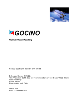
Determination of Orthometric Heights with Real Time Kinematic
Surveying, Konya Sample
Ismail SANLIOĞLU, Süleyman Sırrı MARAS and Fatih UYSAL, Turkey
Key words: GPS, Positioning, RTK, geoid determination, surface fitting
SUMMARY
GPS provides measures of heights above a reference ellipsoid, such as the WGS84 ellipsoid,
as a perpendicular distance from the ellipsoid surface. However, orthometric heights are
measured by perpendicular distance from the geoid. The ellipsoidal heights obtained by GPS
do not be used in practical geodesy. To obtain orthometric heights from ellipsoidal heights, it
is required that geoid undulations are known. In a mission area, if height differences of geoid
rather than geoid heights and orthometric height of one point are known, it is possible to
calculate orthometric heights of other points.
In this study, usage of geoid undulations at real time kinematic surveying has been
investigated. GPS network had been established according to Big Scale Map and Map
Information Production Regulations in Konya metropolitan city at 2008. There are 6 Turkish
National Fundamental GPS Network (TUTGA) points, 8 stations graded by C1, 24 stations
graded by C2 and 1218 stations graded by C3 appropriately to the Big Scale Map and Map
Information Production Regulations (BSH&MIPR) in the study area, Total area is
approximately 1800 square km. Geometric leveling had been carried out to determine
orthometric heights of unknown heights of stations using by digital levels.
Konya geoid model had been determined using second order-nine parameter multi-quadratic
surface fitting benefiting 1175 control points. Root mean square of model is ± 4.5 cm. Geoid
undulations of 30’’x30’’ spacing grid points were computed from Konya geoid parameters to
use in regional geoid model file (rgm format) for Topcon RTK GPS receivers. The
orthometric heights obtained by Topcon receivers have been compared with original heights
in the chosen test area.
TS3 – Geoid Modelling
Ismail Sanlioğlu, Süleyman Sırrı Maras and Fatih Uysal
Determination of Orthometric Heights with Real Time Kinematic Surveying, Konya Sample
FIG Working Week 2009
Surveyors Key Role in Accelerated Development
Eilat, Israel, 3-8 May 2009
1/11
Determination of Orthometric Heights with Real Time Kinematic
Surveying, Konya Sample
Ismail SANLIOĞLU, Süleyman Sırrı MARAS and Fatih UYSAL, Turkey
1. INTRODUCTION
However, today, the position and the height of a point on the ground can be precisely
determined by GPS in WGS84 datum. The spatial information about the point cannot be used
directly in the practical engineering and mapping projects. Because the coordinate systems,
which are currently in use by several groups of countries, are not referred to the same
reference datum and the heights must also be transferred to the geopotential surfaces at the
points. The calculations for the point positioning are done on the International Hayford
ellipsoid in Turkey and then the coordinates of the point are determined in Gauss-Krueger
coordinate system. The height of a point in Turkey is referred to the tide gauge station in
Antalya. Therefore, it is presently compulsory to transform the ellipsoidal heights and the
positions by GPS to the local datum in use for Turkey. Under the scope of this project, it was
studied the usage of geoid undulations at real time kinematic (RTK) surveying. Geoid
undulations at the points of interest were determined with respect to RTK and using regional
geoid model (rgm) file derived from multi-quadratic interpolation technique and known
orthometric heights and RTK results from study were then compared with each other.
2. RELATIONSHIP BETWEEN ELLIPSOIDAL AND ORTHOMETRIC HEIGHTS
For geophysical applications, gravity is distinguished from gravitation. Gravity is defined as
the resultant of gravitation and the centrifugal force caused by the Earth's rotation. The global
mean sea surface is close to one of the equipotential surfaces of the geopotential of gravity.
This equipotential surface, or surface of constant geopotential, is called the geoid.
The geoid is that level surface of the Earth's gravity field coincides with the mean ocean
surface (Torge, 1980).It is that equipotential surface (surface of fixed potential value) which
coincides on average with mean sea level
The geoid is essentially the shape of the earth abstracted from its topographic features. It is an
idealized equilibrium surface of sea water, the mean sea level surface in the absence of
currents, air pressure variations etc. and continued under the continental masses. The geoid,
unlike the ellipsoid, is too complicated to serve as the computational surface on which to
solve geometrical problems like point positioning.
The geoid surface is more irregular than the ellipsoid of revolution often used to approximate
the shape of the physical Earth, but considerably smoother than Earth's physical surface. The
geometrical separation between it and the reference ellipsoid (as GRS-80) is called the geoid
undulation. It varies globally between ±110 m. The orthometric height is the distance H along
a line of force from a given point A at the physical surface of an object to the geoid.
TS3 – Geoid Modelling
Ismail Sanlioğlu, Süleyman Sırrı Maras and Fatih Uysal
Determination of Orthometric Heights with Real Time Kinematic Surveying, Konya Sample
FIG Working Week 2009
Surveyors Key Role in Accelerated Development
Eilat, Israel, 3-8 May 2009
2/11
Figure 1. Relative heighting and relationships among height systems.
Ellipsoidal height of a point on physical earth as P is equal to the distance between the point P
and the point where ellipsoid is touched by the line that passes from the point P and is
perpendicular to the ellipsoid. The heights obtained by GPS are ellipsoidal heights and does
not be used in practical geodesy. This ellipsoid is WGS-84 ellipsoid, semi major axis
a=6378137m, flattening a=1/298.257223563 (Leick, 1995). If reference coordinate system is
defined by ITRF datum, the ellipsoidal height is determined on GRS-80 ellipsoid.
2.1 Determination of The Geoid Undulations by GPS/Leveling
The ellipsoidal heights are obtained after the process of GPS observations as the orthometric
heights after leveling. As can be seen from (Fig. 1), the geoid undulation is calculated by
Equation (1) [Liddle, 1989;Ollikainen, 1997].
where
N =h− H
(1)
h is the ellipsoidal height, and
H is the orthometric height.
To obtain orthometric heights from ellipsoidal heights determined by GPS, it is required that
geoid undulations (N) are known. In a mission area, if height differences of geoid rather than
geoid heights and orthometric height of one point are known, it is possible to calculate
orthometric heights of other points. Ellipsoidal heights hA and hB of points A and B can also
be determined by means of Equation (2), as below;
Using equation (2)
∆hBA = hA− hB = ( H A− H B ) + ( N A− N B ) = ∆H BA + ∆N BA
(2)
TS3 – Geoid Modelling
Ismail Sanlioğlu, Süleyman Sırrı Maras and Fatih Uysal
Determination of Orthometric Heights with Real Time Kinematic Surveying, Konya Sample
FIG Working Week 2009
Surveyors Key Role in Accelerated Development
Eilat, Israel, 3-8 May 2009
3/11
and
∆H BA = ∆hBA − ∆N BA
(3)
can easily be derived (Sideris, 1990). As ellipsoidal height difference is known by GPS, only
one problem is computing of dN geoid undulation difference. The basic geoid undulation
determination techniques are
1. Astro-geodetic method.
2. Geopotential models
3. Use of surface gravity in techniques such as Stokes' Integral
4. Geometric or interpolation methods: a local representation of the geoid is obtained
only at points which have both leveled (orthometric) heights and heights derived using GPS
(ellipsoidal). Geoid heights at other points are found by interpolation.
3. MULTIQUADRATIC INTERPOLATION TECHNIQUE
There are several interpolation techniques, which are developed for the transformation of
GPS ellipsoidal heights to orthometric heights. Selection of the interpolation technique
depends on GPS/Leveling and the number and the position of the points with known height.
Here is only explained the multiquadratic interpolation technique, since this technique was
chosen as the interpolation technique, which bets fits to the data obtained in this project.
The multiquadratic interpolation technique was suggested by Hardy [1971]. The purpose of
this interpolation technique is to define the best matching surface to the region of interest by a
single function using the entire control points known. It is also an analytic solution technique.
For the application of the technique, a trend surface must be drawn. As a trend surface in this
technique, it is appropriate to use first and second degree polynomials [Leberl, 1973].
N trend ( x, y) = a0 + a1 y + a2 x + a3 xy + a4 y 2 + a5 xy 2 + a6 x 2a7 x 2 y + a8 x 2 y 2
(3)
If a second degree polynomial which is not orthogonal, which is used the surface function can
be written as Equation (3). Nine control points are required for the solution of this function. If
the number of control points is more than 9, ai coefficients are calculated using the least
square adjustment technique [Inal, 1996]. Taking the advantage of trend surface, the geoid
undulation of a point with x and y plane coordinates can be calculated by Equation (4).
n
[
N ( x , y ) = N trend + ∑ C i ( x i − x ) + ( y i − y )
i =1
2
]
1/ 2
2
(4)
where
n stands for the items control points, and
ci are the coefficients calculated by means of known N(x,y) values of the control points
TS3 – Geoid Modelling
Ismail Sanlioğlu, Süleyman Sırrı Maras and Fatih Uysal
Determination of Orthometric Heights with Real Time Kinematic Surveying, Konya Sample
FIG Working Week 2009
Surveyors Key Role in Accelerated Development
Eilat, Israel, 3-8 May 2009
4/11
This interpolation technique does not show any fitting residuals the positions the control
points (Çorumluoğlu and et al, 2002).
4. REAL TIME KINEMATIC AND KONYA SINGLE REFERENCE STATION FOR
RTK
Real Time Kinematic (RTK) satellite navigation is a technique used in land survey and in
hydrographic survey based on the use of carrier phase measurements of the GPS, GLONASS
and/or Galileo signals. RTK systems use a single base station receiver and a number of
mobile units. The base station re-broadcasts the phase of the carrier that it measured, and the
mobile units compare their own phase measurements with the ones received from the base
station. This allows the units to calculate their relative position to millimeters, although their
absolute position is accurate only to the same accuracy as the position of the base station. The
typical nominal accuracy for these dual-frequency systems is 1 centimeter ± 2 parts-permillion (ppm) horizontally and 2 centimeters ± 2 ppm vertically. Also these values may
change according capabilities of GPS receiver, communication, distance between base
receiver and the rover receiver, distance-dependent biases, namely orbit bias, ionosphere bias
and troposphere bias.
In October 2008 Konya Municipality started operating single reference station for RTK
positioning, whereby users can receive the corrections throughout the Konya Municipality
boundary. Topcon NET G3 reference station receiver was employed. This reference station is
controlled by a central server. TopNET 7.12 Reference Station software is used for data
processing.
The reference station sends its GPS measurements online to the control room server by
dedicated telephone lines. One PC organizes process and archive the data. Communication
with the rover is carried out NTRIP protocol, whereby the rover sends its approximate
position, calculated in a single positioning mode, to the control station via a GSM mobile call
in a National Marine Electronics Association (NMEA) format. Then, the corrections are
calculated at the user location and are sent in Radio Technical Commission for Maritime
services (RTCM 2.3) format, and used to correct the data to reach cm-level positioning. The
coordinates of the reference station is related to the ITRF96 system (reference epoch 1998.00)
and the computed rover position can be represented either in this system or in the local one.
5. THE MEASUREMENTS IN THE WORKING AREA AND THE EVALUATION
In this study, usage of geoid undulations at real time kinematic surveying has been
investigated. GPS network for Konya Photogrammetrical Mapping Project had been
established according to Big Scale Map and Map Information Production Regulations in
Konya metropolitan city in autumn 2007. There are 6 items Turkish National Fundamental
GPS Network (TUTGA) points, 8 stations graded by C1, 24 stations graded by C2 and 1218
stations graded by C3 appropriately to the Big Scale Map and Map Information Production
Regulations (BSH&MIPR) in the study area, Total area is approximately 1800 square km.
TS3 – Geoid Modelling
Ismail Sanlioğlu, Süleyman Sırrı Maras and Fatih Uysal
Determination of Orthometric Heights with Real Time Kinematic Surveying, Konya Sample
FIG Working Week 2009
Surveyors Key Role in Accelerated Development
Eilat, Israel, 3-8 May 2009
5/11
GPS observations were collected within the epochs of 10" interval for 30 minutes observation
period at total 1369 points in the working area, with respect to the static GPS observation
technique. The coordinates of 151 points were used for fixed adjustment at different sessions.
During the collection of GPS observations, 4 items Leica System 1200 receivers and
LEIATX1230 antenna and 4 Javad GPS receivers and JPSODYSSEY_I integrated antennas
were used. The measurements were completed in 25 days in May and in June 2007. GPS data
was processed and adjusted session by session in Pinnacle 1.0 GPS commercial software
(Table 1). The antenna library of Pinnacle was used for phase center variation.
Geometric leveling had been carried out to determine orthometric heights of stations by three
measurement teams using 3 items Topcon DL-101C, Topcon DL-102C and Sokkisha SDL30
Digital Levels. The measurements completed in 5 months between April-July 2007. The
geometric leveling network has 2843 height difference (measurements) and 1885 stations.
Thus Konya vertical control network (KVC network) established .Then this network adjusted
in one go using 6 points whose coordinates were known in Turkey National Vertical Control
Network (TUDKA). The root mean square of leveling adjustment is ±7.56 mm.
Table 1: The processing parameters of Pinnacle Software used in
Konya Photogrammetrical Mapping Project
Elevation Mask (degrees)
Tropospheric model
Solution type
Ephemeris
Data used
Min Measurements (%)
Max İteration
Measurement Tolerance
Convergence (meters)
Contrast Threshold
15
Goad&Goodman
Auto (Double Difference , L1&L,
Iono Free, Wide Lane)
Broadcast
Use Code and Phase
10
6
3
0.001
0.95
The second order-nine parameter multi-quadratic surface was fitted to the topography by
using well distributed 1175 control points. Root mean square of surface is ± 4.5 cm. The
multi-quadratic surface equation is;
N = a1 + a 2 y + a 3 x + a 4 y 2 + a 5 xy 2 + a 6 xy + a 7 x 2 + a 8 x 2 y + a 9 x 2 y 2
(8)
and coefficients of equations are shown Table 2.
TS3 – Geoid Modelling
Ismail Sanlioğlu, Süleyman Sırrı Maras and Fatih Uysal
Determination of Orthometric Heights with Real Time Kinematic Surveying, Konya Sample
FIG Working Week 2009
Surveyors Key Role in Accelerated Development
Eilat, Israel, 3-8 May 2009
6/11
Table 2. Coefficients of multi-quadratic
surface equations
a1 = 35.848719452232800 m.
a2 = -0.000006229550258
a3 =
0.000005929540559
a4 = 0.000000000004456
a5 = -0.000000000000024
a6 = -0.000000000230247
a7 = -0.000000000108540
a8 = 0.000000000000025
a9 = 0.000000000000000
Figure 2: Entering geoid heights
Geoid undulations of 30’’x30’’ spacing grid points were computed from coefficients of multiquadratic surface to use in regional geoid model file (*.rgm) for Topcon RTK GPS receivers.
Regional geoid model format is shown in Table 3 and Figure 2. The *.rgm file was converted
to a Topcon geoid file (*.gff) by using Topcon link software.
Table 3. Regional Geoid Model Format
Format Fields
Example
LAT,LON, n_row, n_column, step_lat,step_lon, 37 43 30, 32 21 00, 45, 50, 00 30, 00 30,
geoid_direction, ellipsoid;
NE, GRS80;
H1 H2 H3
35.807 35.815 35.823
H4 H5 H6
35.785 35.795 35.805
H7 H8 H9
35.764 35.776 35.788
5.1 Investigating the Accuracy of the Ellipsoidal and Orthometric Height Values
To assess accuracy of orthometric height determination using rover receivers with single GPS
reference station and GPS ellipsoidal height and the interpolated orthometric height has to be
separately examined, and then jointly evaluated. This helps in showing their performance as
well as understating the contribution of each in the total error budget.
A comprehensive testing of GPS heights and horizontal coordinates’ determination using the
reference station has been carried out by two items Topcon GR3 double frequency receiver on
March 16-18 2009. The observation time for RTK is 9 second. The orthometric heights of 34
points obtained by Topcon receivers have been compared with original heights in the chosen
test area. But 29 points were used for the orthometric height testing. Because the root mean
square of height discrepancies was bigger than 3σ in 5 points. However 28 points were used
in the comparison of ellipsoidal heights because of same convention (Figure 3).
TS3 – Geoid Modelling
Ismail Sanlioğlu, Süleyman Sırrı Maras and Fatih Uysal
Determination of Orthometric Heights with Real Time Kinematic Surveying, Konya Sample
FIG Working Week 2009
Surveyors Key Role in Accelerated Development
Eilat, Israel, 3-8 May 2009
7/11
Figure 3. Topograhy of Konya City, created by GMT (Wessel and Smith, 1998).
Comparing the point coordinates of 29 points which were previously precisely determined
with their coordinates determined by RTK gave horizontal positioning accuracy l.8 cm in
easting, 2 cm in northing. These surveys also prove to be consistent in terms of the internal
precision of their final output results (i.e. statistically compatible).
The height difference between the highest and lowest points in the test area was
approximately 377.4 meters. Figure 4 shows the difference in orthometric height between
estimated leveling adjustment and obtained RTK with geoid model (the geoid model + GPS
TS3 – Geoid Modelling
Ismail Sanlioğlu, Süleyman Sırrı Maras and Fatih Uysal
Determination of Orthometric Heights with Real Time Kinematic Surveying, Konya Sample
FIG Working Week 2009
Surveyors Key Role in Accelerated Development
Eilat, Israel, 3-8 May 2009
8/11
fh (leveling -RTK geoid model)
ellipsoidal heights). The height discrepancies were in the range ± 18 cm. The statistics of these
discrepancies are given in Table 4 where the mean value was 0.031m with random
distribution of the differences, and no systematic errors were observed. The average value of
the absolute differences was ±1.9 cm with ± 2.33 cm rms of differences
0.20
0.15
0.10
0.05
0.00
-0.05
-0.10
-0.15
-0.20
0
5
10
15
Points
20
25
30
Fig. 4 Height differences between RTK using regional geoid model and
estimated leveling adjustment (m)
Table 4. Height differences between RTK using regional
geoid model and known heights (m)
Average
Orthometric
Ellipsoidal
0.031 m
0.008 m
Average of
Absolute values
0.094 m
0.039 m
Maximum
Discrepancy
0.184 m
0.101 m
Minimum
RMS
Discrepancy
σ
0.010 m
0.107 m
0.002 m
0.052 m
The results show that there are no systematic errors either in ellipsoidal height determination
by GPS. The difference in orthometric height between estimated leveling adjustment and
obtained RTK with geoid model (the geoid model + GPS ellipsoidal heights) can be attributed
to
a) random noise in the values of h, H, N in KVC network
b) datum inconsistencies and other possible systematic distortions in the three height data
sets (e.g. long-wavelength systematic errors in N, distortions in the vertical datum due
to an over constrained adjustment of the leveling network, deviation between
gravimetric geoid and reference surface of the leveling datum) (El-Mowafy et al,
2006).
6. CONCLUSIONS
The feasibility of determining real-time orthometric heights by RTK at the cm-level accuracy
level is shown in Konya. The RTK GPS survey technique may be an efficient and accurate
alternative to the leveling techniques currently being used. On average the results agree to
within 10 cm. The regional geoid model was estimated from second degree multi-quadratic
TS3 – Geoid Modelling
Ismail Sanlioğlu, Süleyman Sırrı Maras and Fatih Uysal
Determination of Orthometric Heights with Real Time Kinematic Surveying, Konya Sample
FIG Working Week 2009
Surveyors Key Role in Accelerated Development
Eilat, Israel, 3-8 May 2009
9/11
surface in this study. According to ellipsoidal heights, the deviations of orthometric heights
are double big. The estimated surface may be incompatible with topography. However,
further tests on the larger network with a greater number of stations may provide more insight
to RTK with geoid model method as an alternative to leveling.
ACKNOWLEDGEMENTS
The Map Department of Konya Municipality is acknowledged for the dedicated help and
efforts in completing this study. Survey Engineer and Chief of Map Department Celal Can,
Barbaros Ipek, and their team are gratefully acknowledged for their help in the land
surveying, and data collection. The Manager of OSTEM Mapping Corporation and Eng.
Erhan Civcik also thanked receiving data as regards GPS network for Konya
Photogrammetrical Mapping Project.
REFERENCES
Çorumluoglu, Ö., Inal C., Ceylan, A., Sanlıoğlu, I., Kalayci, I., 2002, Determination of
Geoid Undulations in the Region of Konya, International Symposium on GIS,
September 23-26, Istanbul, Turkey
El-Mowafy, A., Fashir, H., Al Habbai, A. Al Marzooqi, Y. and Babiker, T. 2006, RealTime Determination of Orthometric Heights Accurate to the Centimeter Level
using a Single GPS Receiver: Case Study, Journal of Surveying Engineering, Vol.
132, No. 1, pp. 1-6.
Hardy, R.L., 1971, Multiquadratic Equation of Topography and Other Irregular Surfaces,
Journal of Geophysical Research, Vol.76, No 8
Inal, C., 1996, Height Determination from GPS using local geoid, Journal of Engineering and
Architectural Faculty of S.U., Vol 11, No 2, pp 15-21
Leberl, F., 1973, Interpolation in a Square Grid DTM, ITC Journal, 1973-75
Leick, A., 1995, GPS Satellite Surveying, Second Edition, John Wiley&Sons, Inc.
Liddle, L. A., 1989, Orthometric Height Determination by GPS, Surveying and Mapping, Vol
49, No 1,
Ollikanen, M., 1997, Determination of Orthometric Heights using GPS leveling, Publication
of the Finnish Geodetic Institute, No 23, Kirkkonum
Sideris, M. G., 1990. The role of the geoid in one-, two-, and three-dimensional network
adjustments. CISM Journal ACSGC, 44 (1) : 9-18.
Torge, W., 1980. Geodesy, Walter de Gruyter, Berlin-New York.
Wessel, P. and Smith.,W. H. F., 1998, New, improved version of the Generic Mapping
Tools Released, EOS Trans. AGU, 79, 579.
TS3 – Geoid Modelling
Ismail Sanlioğlu, Süleyman Sırrı Maras and Fatih Uysal
Determination of Orthometric Heights with Real Time Kinematic Surveying, Konya Sample
FIG Working Week 2009
Surveyors Key Role in Accelerated Development
Eilat, Israel, 3-8 May 2009
10/11
CONTACTS
Assist. Prof. Dr. Ismail Sanlıoğlu
Selcuk University, Engineering and Arhitecture Faculty
Geodesy and Photogrammetry Department
University Lecturer, Süleyman Sırrı Maras
Selcuk University, Technical Sciences Vocational School of Higher Education
Mapping-Cadastre Programme, Konya
Research Assist. Fatih Uysal
Selcuk University, Engineering and Arhitecture Faculty
Geodesy and Photogrammetry Department
Konya
TURKEY
Tel. +90 332 2231940
Fax + 90 332 2410635
Email: [email protected], [email protected], [email protected],
TS3 – Geoid Modelling
Ismail Sanlioğlu, Süleyman Sırrı Maras and Fatih Uysal
Determination of Orthometric Heights with Real Time Kinematic Surveying, Konya Sample
FIG Working Week 2009
Surveyors Key Role in Accelerated Development
Eilat, Israel, 3-8 May 2009
11/11


© Copyright 2026