
Use of the BOs-1EP for the low-sample estimation of the... Fachhochschule Osnabrück University of Applied Sciences S. Hinck
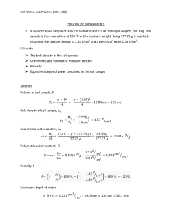
Fachhochschule Osnabrück
University of Applied Sciences
Use of the BOs-1EP for the low-sample estimation of the spatial distribution of grain sizes
*
**
**
S. Hinck , K. Mueller , N. Emeis , O. Christen
***
FARMsystem Hinck&Kielhorn, PO Box 1965, 49009 Osnabrueck, Germany, E-Mail: [email protected]
**
University of Applied Sciences Osnabrück, P.O.Box 1940, 49009 Osnabrück / Germany
***
Institute of Agronomy and Crop Science, Agricultural Faculty, Martin-Luther-University Halle-Wittenberg, 06099 Halle/Saale / Germany
*
Introduction
Information concerning field characteristics, e.g. the soil particle size distribution, is of great importance for practical farming, especially if the farmer are
using precision farming. By using geoelectrical systems to record the electrical properties of the soil the mapping expenditure for e.g. the determination
of the soil texture may be reduced. The measured electrical conductivity correlates with the soil texture. Hence different conductivity values reveal
differences in soil properties. In that way soil particle size may be determined by means of electrical conductivity measurements.
Material and Method
Comparison of the three used measurement systems
BOs-1EP
ARP03
EM38
Measurement method
Detection of the complex electrical conductance
Direct current, four-terminal electrode arrays
Electromagnetic
Electrical contact
(sensor <> soil)
Galvanic (direct contact measurement)
Galvanic (direct contact measurement)
Induction (contactless)
Electrical excitation
Electrode
Transmitting electrode
Transmitting coil
Frequency
125.000 Hz
150 Hz
14.600 Hz
Electrode depth: 25 cm
Electrode arrangement 1 (EC1)
Measured depth: 0 – 50 cm
Horizontal dipole mode: 63% of the signal response
describe a depth down to 60 cm
Measurement property
Defined measured volume in a defined depth
Measurement is the integral over the measured
depth
Measurement is the integral over the measured
depth
Date of measuring
14. March 2007
Autumn 2004
14. March 2007
Measurement depth
Test field
The measurements were carried out on an agricultural field of the University of Applied Sciences Osnabrück. This field is divided into 10m * 10m grid
cells, each of which is pedologically mapped. The total number of all grid cells is 224. The soil samples were taken over a depth of 0 – 30 cm. In the
laboratory the soil particle size (sand, silt and clay) was analysed based on a sedimentation analysis, exemplified the clay content is shown. (s. Fig. 1)
Estimation of the soil particle size by using a regression equation
The regression is based on a selection of seven grid cells and transferred to all grid cells. The calculated estimate value is computed with the analyzed
value. A negative value describes an underestimation and a positive value describes an overestimation (s. Fig. 2, 3 and 4). The total and relative hits
are listed in Tab 1.
Results
BOs-1EP
Fig. 1: Analyzed clay content
(measuring depth 0 – 30 cm)
Fig. 2: BOs-1EP: Estimated clay content (s. value at grid cell);
yellow-orange-red coloring shows the spatial distribution of the
electrical conductivity (left hand side); Difference between
analyzed (s. fig 1) and estimated clay content for each grid cell
(right hand side)
Fig. 3: ARP03: Estimated clay content (s. value at grid cell);
yellow-orange-red coloring shows the spatial distribution of
the electrical conductivity (left hand side); Difference
between analyzed (s. fig. 1) and estimated clay content for
each grid cell (right hand side)
BOs-1EP
Tab. 1: Hits of the soil particle
size estimation with an accepted
deviation (in percentage points)
to the analyzed value for each
soil sensor system (n = 224)
Sand
Difference in
percentage
hits
hits
points
(count) (%)
Fig. 4: EM38: Estimated clay content (s. value at grid cell);
yellow-orange-red coloring shows the spatial distribution of the
electrical conductivity (left hand side); Difference between
analyzed (s. fig. 1) and estimated clay content for each grid cell
(right hand side)
ARP03
Silt
Clay
Sand
EM38
Silt
Clay
Sand
Silt
Clay
hits
(count)
hits
(%)
hits
(count)
hits
(%)
hits
(count)
hits
(%)
hits
(count)
hits
(%)
hits
(count)
hits
(%)
hits
(count)
hits
(%)
hits
(count)
hits
(%)
hits
(count)
hits
(%)
0
13
6
30
13
20
9
16
7
32
14
20
9
9
4
28
13
12
5
±1
42
19
91
41
69
31
39
17
95
42
67
30
32
14
89
40
57
25
±2
82
37
147
66
114
51
69
31
134
60
106
47
57
25
144
64
98
44
±3
107
48
178
79
161
72
95
42
171
76
135
60
78
35
174
78
126
56
±4
130
58
201
90
183
82
112
50
202
90
160
71
107
48
199
89
145
65
±5
153
68
214
96
201
90
130
58
213
95
177
79
132
59
212
95
161
72
±6
174
78
219
98
211
94
148
66
219
98
194
87
152
68
222
99
178
79
Discussion
It is possible to do a acceptable estimation of the soil particle size by using the geoelectrical measuring results. The mapping expenditure can be
reduced clearly. The spatial distribution of grain sizes is an important information for the farmer to optimize the plant production.
Comparing the estimation results of the three different measuring principles the both galvanic working systems shows a higher accuracy of hits than the
inductive working system does. Furthermore the estimation results of the BOs-1EP show a higher accuracy of hits than the ARP03 does.
current (I)
voltage (U)
phase shifting (- 90°)
Interdisciplinary Research Project PIROL
Sub-project Soil Sciences / Soil Sensors Technology
current (I)
voltage (U)
magnitude of current
Funded by:
Sub-project Prof. Dr. Klaus Mueller (Soil Sciences)
manager:
Prof. Dr. Norbert Emeis (Soil Sensors Technology)
Contact:
Dr. agr. Stefan Hinck
Internet:
www.pirol.fh-osnabrueck.de
zero-crossing
time
zero-crossing
phase shifting
time


© Copyright 2026