
Manual of Standard Operating Procedures for Sample Collection and Analysis
Manual of Standard Operating Procedures for Sample Collection and Analysis Wyoming Department of Environmental Quality Water Quality Division Watershed Protection Program Wyoming Department of Environmental Quality John Corra, Director John Wagner Water Quality Division Administrator e-mail address: [email protected] David Waterstreet Program Manager Watershed Protection Program e-mail address: [email protected] Water Quality Division Contact Information Phone Cheyenne 307 777-7781 Casper 307 473-3465 Lander 307 332-3144 Sheridan 307 673-9337 Cheyenne Casper Lander Sheridan Fax 307 777-5973 307 473-3458 307 332-7726 307 672-2213 Division Internet Site deq.state.wy.us Watershed Protection Program Mail Address State of Wyoming Department of Environmental Quality Water Quality Division, Watershed Protection Program Program Manager 122 West 25th Street, 4W Cheyenne, Wyoming 82002 Persons who require additional information about or alternative means for communication of the information in this manual should contact Jeff Clark Phone: 307-777-6891 Fax: 307-777-5973 e-mail: [email protected] Updated by Karen Jackson (November 2011) The State of Wyoming, Department of Environmental Quality, Water Quality Division, Watershed Protection Program does not discriminate on the basis of race, color, national origin, gender, religion, age, disability, political beliefs and/or marital or familial status. Published by the Wyoming Department of Environmental Quality, Water Quality Division, Watershed Protection Program Cheyenne, Wyoming 82002 Originally produced in part with funding provided by the United States Environmental Protection Agency under a Clean Water Act Section 319(h) grant Printed on recycled paper Suggested Citation Information WDEQ/WQD. 2011. Manual of Standard Operating Procedures for Sample Collection and Analysis. Wyoming Department of Environmental Quality, Water Quality Division, Watershed Program, Cheyenne, WY. Manual of Standard Operating Procedures for Sample Collection and Analysis Wyoming Department of Environmental Quality, Water Quality Division, Watershed Protection Program TABLE OF CONTENTS INTRODUCTION ...................................................................................................................................................... 1 BACKGROUND ...................................................................................................................................................... 1 PURPOSE .............................................................................................................................................................. 1 DEFINITION ......................................................................................................................................................... 1 DOCUMENT ORGANIZATION .................................................................................................................................. 2 USE OF SOPs ......................................................................................................................................................... 2 SCIENTIFIC VALIDITY ............................................................................................................................................. 2 QUALITY CONTROL ............................................................................................................................................... 2 COMPARABILITY .................................................................................................................................................... 2 SAFETY ................................................................................................................................................................ 3 UPDATES .............................................................................................................................................................. 3 DISCLAIMER ......................................................................................................................................................... 3 AUDITS ................................................................................................................................................................ 3 INCORPORATED REFERENCES ................................................................................................................................. 3 OTHER REFERENCES AND SUPPLEMENTAL INFORMATION ......................................................................................... 4 PART 1 - SAMPLE PLANNING AND SITE LOCATIONS ................................................................................ 5 Above and Below Monitoring (Effective Date: March 2001) ............................................................................................ 6 Below Only Monitoring (Effective Date: March 2001) .................................................................................................. 7 Field Monitoring Equipment Checklist (Effective Date: November 2011) ............................................................................. 8 Macroinvertebrate Sampling Index Period (Effective Date: November 2011) ...................................................................... 10 Monitoring Field Data Sheet Review (Effective Date: September 2004) ............................................................................. 11 Monitoring Procedure Sequence (Standard) (Effective Date: November 2011) ..................................................................... 12 Nonpoint Source (NPS) Pollution Bioassessments (Effective Date: November 2011) .............................................................. 36 Paired Stream/Paired Watershed Monitoring (Effective Date: March 2001)....................................................................... 38 Pre-Monitoring Inventory (Lentic) (Effective Date: September 2004) ................................................................................ 39 Pre-Monitoring Inventory (Lotic) (Effective Date: November 2011) ................................................................................. 40 Sample Location Determination (Lentic) (Effective Date: September 2004) ........................................................................ 43 Sample Location Determination for Probabilistic Surveys (Lotic) (Effective Date: November 2011) ........................................... 45 PART 2 - BIOLOGICAL SAMPLING .................................................................................................................. 47 Chlorophyll (Lentic) (Effective Date: November 2011) ................................................................................................. 48 Periphyton: Sampling Methods and Subsample Processing for Chlorophyll Analysis and Taxonomic Identification (Lotic) (Effective Date: November 2011) .................................................................................................................................................... 50 Coliform Bacteria Sampling Procedure (Effective Date: November 2011) ........................................................................... 59 Escherichia coli & Total Coliform Bacteria Colilert®-Defined Enzyme Substrate Method (Effective Date: March 2004) ................. 63 Fecal Coliform Bacteria M-FC Method (Effective Date: March 2004) ............................................................................... 69 Geometric Mean, Calculating and Using (for Escherichia coli test results) (Effective Date: September 2004)..................... 75 Macroinvertebrate Sample Identification (Effective Date: September 2004) ........................................................................ 77 Macroinvertebrate Sample Packing and Shipping (Effective Date: September 2004) ............................................................. 82 Macroinvertebrate Sample Preservation (Effective Date: September 2004) .......................................................................... 83 Macroinvertebrate Sampling – Method Selection (Effective Date: November 2011) .............................................................. 84 Macroinvertebrate Sampling – Targeted Riffle Method (Effective Date: November 2011) ...................................................... 86 Macroinvertebrate Sampling – Multi-habitat Method (Effective Date: November 2011) ........................................................ 89 iv Macroinvertebrate Processing – Large Volume Benthic Samples (Effective Date: November 2011) ............................................ 91 Periphyton Sample Preservative – Lugol’s Solution (Effective Date: September 2004) ........................................................... 92 PART 3 - PHYSICAL SAMPLING ....................................................................................................................... 93 Bank Stability, Evaluating (Effective Date: September 2004) ........................................................................................ 94 Bankfull Elevation – Field Identification (Effective Date: November 2011) ....................................................................... 95 Bankfull Width, Determining (Effective Date: September 2004) ................................................................................... 103 Bar Sampling (Effective Date: November 2011) ....................................................................................................... 104 Channel Cross Section – Survey Method (Effective Date: November 2011) ....................................................................... 106 Current Velocity – Wadeable Streams and Rivers (Effective Date: November 2011) ............................................................ 108 Geology Abbreviations, Surficial (stratigraphic units in Wyoming) (Effective Date: Septemeber 2004) ..................................... 110 Global Positioning System (GPS) Data (Effective Date: Septemeber 2004) ....................................................................... 114 Habitat Type Delineation – Wadeable Streams and Rivers (Effective Date: November 2011) ................................................ 116 Longitudinal Profile – Survey Method (Effective Date: November 2011) ......................................................................... 117 Pebble Counts – Reachwide and Cross-Sections (Effective Date: November 2011).............................................................. 119 Pool Quality – Wadeable Streams and Rivers (Effective Date: September 2004) ................................................................ 121 Reachwide and Riffle Gradients – Survey Method (Effective Date: November 2011) ........................................................... 122 Riffle Embeddedness – Wadeable Streams and Rivers (Effective Date: November 2011) ....................................................... 124 Riffle Gradient – Clinometer Method (Effective Date: September 2004) .............................................................................. 129 Rosgen Channel Type Classification (Effective Date: November 2011) ............................................................................ 130 Shoreline Habitat (Lentic) (Effective Date: March 2001) ............................................................................................ 132 Strahler Stream Order (Effective Date: Septemeber 2004) ........................................................................................... 135 Stream Discharge – Wadeable Streams and Rivers (Effective Date: Septemeber 2004) ......................................................... 136 Streambank Erosion – Bank Profiles (Effective Date: November 2011) ............................................................................ 140 Soil Type Abbreviations and Definitions (Effective Date: September 2004) ...................................................................... 142 Temperature (Lentic) (Effective Date: March 2001)................................................................................................... 143 Water Transparency (Lentic) (Effective Date: March 2001) ......................................................................................... 144 Width to Depth Ratio – Non Survey Method (Effective Date: September 2004) ................................................................ 145 PART 4 - CHEMICAL SAMPLING ................................................................................................................... 146 Biochemical Oxygen Demand (BOD) 5 Day, 20C (Effective Date: September 2004) ......................................................... 147 Chemical Field Measurement Procedure – Effluent(Effective Date: January 2012) ............................................................. 148 Chemical Field Measurement Procedure - Lentic(Effective Date: January 2012)................................................................. 149 Chemical Field Measurement Procedure - Lotic(Effective Date: January 2012) .................................................................. 150 Chemical Grab Sampling Procedure - Effluent(Effective Date: January 2012) .................................................................. 151 Chemical Grab Sampling Procedure - Lentic(Effective Date: January 2012) ..................................................................... 152 Chemical Grab Sampling Procedure - Loti(Effective Date: January 2012)c ...................................................................... 153 Chemical Integrated Sampling Procedure – Lotic(Effective Date: January 2012) ............................................................... 154 Chemical Monitoring Parameters(Effective Date: January 2012) ................................................................................... 155 Chlorine, Total Residual (Effective Date: September 2004) ......................................................................................... 158 Chromium, Hexavalent (Chromium VI) (Effective Date: September 2004) ....................................................................... 159 Conductance, Specific (Conductivity) (Effective Date: September 2004) .......................................................................... 160 Dissolved Metals Filtration Procedure (Effective Date: November 2011) ......................................................................... 161 Dissolved Oxygen (DO) (Effective Date: September 2004) ........................................................................................... 162 Herbicides/Pesticides (Effective Date: September 2004) .............................................................................................. 164 Metals, Total and Dissolved (Effective Date: September 2004) ..................................................................................... 165 Nitrogen, Nitrate – Nitrite (Effective Date: September 2004) ...................................................................................... 167 Nitrogen, Total Kjeldahl (Effective Date: September 2004) ........................................................................................ 168 Orthophosphate (Effective Date: September 2004) .................................................................................................... 169 v pH (Effective Date: September 2004) .................................................................................................................... 170 Phenols (4-AAp Method) (Effective Date: September 2004) ......................................................................................... 172 Phosphorus, Total (Effective Date: September 2004).................................................................................................. 173 Sample Bottles, Polyethylene (Effective Date: September 2004) .................................................................................... 175 Temperature, Water (Effective Date: September 2004) ............................................................................................... 176 Total Suspended Solids (TSS) (Effective Date: September 2004) ................................................................................... 177 Turbidity (Effective Date: September 2004) ............................................................................................................ 178 Volatile Organic Analysis (VOA) (Effective Date: September 2004)................................................................................ 180 Volatile Organic Hydrocarbons, Aromatic or "BETX" (Effective Date: September 2004) .................................................... 181 Volatile Organics, Halogenated (Common Solvents) (Effective Date: September 2004) ........................................................ 182 Volatile Organics, Classifying (Effective Date: September 2004) ................................................................................... 183 PART 5 - QUALITY CONTROL, CUSTODY AND REPORTING ................................................................ 185 Abbreviations, Approved, for Test Parameters (Effective Date: March 2001) .................................................................... 186 Aseptic Technique (Effective Date: September 2004) .................................................................................................. 189 Bioassessment Quality Control Criteria (Effective Date: September 2004) ....................................................................... 190 Blanks (Effective Date: September 2004) ................................................................................................................ 191 Glossary of Terms (Lentic) (Effective Date: March 2001) ........................................................................................... 194 Chain of Custody (Effective Date: September 2004)................................................................................................... 196 Cleaning Previously Used Sample BOTTLES (Effective Date: September 2004) ............................................................... 203 Completeness (Effective Date: September 2004) ....................................................................................................... 204 Conversion FACTORS (Effective Date: March 2001) ................................................................................................ 205 Data Archiving (Effective Date: March 2001) ......................................................................................................... 210 Data Filing, Monitoring (Effective Date: August 2011) ............................................................................................. 213 Data Validation (Effective Date: September 2004).................................................................................................... 213 Data Validation Report (Effective Date: September 2004) .......................................................................................... 216 Data Verification (Effective Date: September 2004) .................................................................................................. 218 Data Verification Report (Effective Date: September 2004) ......................................................................................... 221 Duplicates (Effective Date: September 2004) ........................................................................................................... 222 Ecoregion Definition (Effective Date: March 2001) ................................................................................................... 224 Field Log Books (Effective Date: March 2001) ......................................................................................................... 227 Holding Time, Definition of (Effective Date: March 2001) ......................................................................................... 229 Instrument Calibration and Calibration Logs (Effective Date: March 2001) ..................................................................... 230 Macroinvertebrate Reference Collection (Effective Date: March 2001) ............................................................................ 232 Material Safety Data Sheets (MSDS) (Effective Date: March 2001)............................................................................... 233 Monitoring Electronic Data Entry (Effective Date: March 2001) .................................................................................. 234 Photographic Documentation (Effective Date: March 2001) ........................................................................................ 235 Precision (Effective Date: September 2004) ............................................................................................................. 237 Quality Control Measures, Summary of (Effective Date: November 2011)........................................................................ 239 Quality Control Report, Field (Effective Date: September 2004) ................................................................................... 243 Safety and Safety Equipment (Effective Date: March 2004) .......................................................................................2444 Sample Collection (Effective Date: March 2001) ...................................................................................................... 245 Sample Labeling (Effective Date: March 2001) ........................................................................................................ 247 Sample Preservation and Holding Time, Summary of (Effective Date: March 2001) ......................................................... 248 Sampling and Analysis Plan (SAP), Contents of (Effective Date: March 2001) .................................................................. 252 Spikes (Effective Date: September 2004) ................................................................................................................ 273 Split Samples (Effective Date: March 2001) ............................................................................................................ 274 Temperature Blank (Effective Date: September 2004) ................................................................................................ 275 Temperature Logger Calibration and Placement – Wadeable Streams and Rivers (Effective Date: November 2011) ..................... 276 vi Waste Disposal, Field Sampling (Effective Date: March 2001) ..................................................................................... 278 APPENDIX A - SUPPLEMENTAL INFORMATION SOURCES .................................................................. 279 Supplemental Information Sources ............................................................................................................................ 280 APPENDIX B - CALIBRATION FORMS ......................................................................................................... 284 vii INTRODUCTION BACKGROUND Each year federal, state, private and public groups or agencies, industry, academic researchers and interested citizen organizations spend increasing amounts of time and money on water quality monitoring, data analyses and interpretation. In order for the information gathered to be useful to other interested parties and to be used for an accurate, cost-effective and efficient assessment of water quality, all monitoring data must come from comparable project design, methods (including QA/QC), analyses and interpretation. Collaboration among water quality monitoring programs and organizations is possible if there is a technical and administrative framework to promote data comparability and to assure data of known quality. In addition, environmental issues and related data operations are becoming increasingly complex. Existing and anticipated environmental decision-making objectives drive the need to establish a systematic process and structure which assure the data consistency and quality decision makers must have if they are to have confidence in the data which supports their decisions. United States Environmental Protection Agency (USEPA) policy requires that the collection of environmental data by and on behalf of the Agency be supported by a mandatory quality system which includes Standard Operating Procedures (SOPs) to be used during sampling, analysis and related administrative and technical work. No work funded by USEPA and involving the acquisition of environmental data generated from direct measurement activities can be implemented without SOPs in place. Work performed on behalf of USEPA includes activities performed under contracts, assistance agreements (cooperative agreements, grants), interagency agreements, in response to statutory or regulatory requirements and in some cases consent orders and/or agreements negotiated as part of enforcement actions. PURPOSE The purpose of this manual is to provide a reference which documents: • standard sampling and analysis(es) methods, procedures and techniques, • data handling (electronic and paper), • field equipment, • and sampling methods references used to collect environmental data by the Watershed Protection Program and any groups or organizations which collect environmental data on behalf of Wyoming Department of Environmental Quality, Water Quality Division (WDEQ-WQD), Watershed Protection Program under contracts, assistance agreements (cooperative agreements, grants), interagency agreements, in response to statutory or regulatory requirements and in some cases consent orders and/or agreements negotiated as part of enforcement actions. Environmental data include any measurements or information that describe environmental processes, location or conditions; ecological or health effects and consequences; or the performance of environmental technology; information collected directly from measurements and/or produced from models. Environmental data quality assurance and quality control are achieved by adhering to the methods, procedures and techniques in this manual. One goal of all Watershed Protection Program monitoring is to produce comparable data of known and documented quality, and which conforms to the requirements of the state’s statute 35-11-302 (b) (i) and (ii), commonly known as the Credible Data Law. DEFINITION An SOP describes in detail the method to be used to perform routine or repetitive administrative and technical activities. SOPs provide a framework which helps to ensure the quality, consistency and defensibility of the data and to reduce the work effort, errors and training time required to deliver the product. The development and use of SOPs for both technical (measurement) and administrative work is a required part of a quality system. SOPs assure consistency for activities covered by the Watershed Protection Program’s QAPPs and Sampling and Analysis Plans (SAPs). INTRODUCTION 1 DOCUMENT ORGANIZATION The SOP Manual is divided into five Parts: Part 1: Sample Planning and Site Locations; Part 2: Biological Sampling; Part 3: Physical Sampling; Part 4: Chemical Sampling; Part 5: Quality Control, Custody and Reporting. The SOP effective date is listed under the title of each SOP. As SOPs are revised, the revision date will be shown in the Table of Contents in parentheses, for example: (rev Sep 2004). USE OF SOPS SOPs promote quality by assuring a consistency that can be independent of personnel changes. SOPs can, therefore, be used as part of a training program, to reconstruct project activities when no references are available, and to improve data comparability, credibility and defensibility. SOPs do not, however, guarantee that the information collected with them accurately portrays the overall large system (habitat, watershed) associated with the sampling sites because a sample and its resulting data are representative only of the site and field conditions at the time the sample was taken. Even with SOPs, analytical methods and instruments are never absolutely perfect. It is understood that any measurement can only estimate the true value of an environmental sample. The term measurement error refers to a combination of random and systematic errors that inevitably arise during the various steps in the measurement process: sample collection, handling, preparation and analysis; data entry, reduction and verification. In addition, the population (condition) being sampled obviously varies over time and space. Limited sampling, even if it follows SOPs, will miss some features of this natural variation. It is usually impossible or impractical to measure every point of a population. Sampling design error occurs because a sampling design cannot capture the complete extent of natural variability that occurs in the environment. SCIENTIFIC VALIDITY Collected data must be scientifically valid if it is to be useful. The data should be valid quantitatively and qualitatively, and be representative of the environment in which it was collected. Sampling and Analysis Plans (SAPs) should be written to help ensure that data collected will provide the necessary information for the project. The methodologies used should be reproducible and accepted by the scientific community. QUALITY CONTROL A description of the Quality Control is given in each SOP which does not have a Method Reporting Limit, and in summary SOPs in Part 5. Quality control is achieved and maintained when all persons collecting data on behalf of WDEQ-WQD, Watershed Protection Program follow the SOPs so that sample collection, chain of custody, data entry, sample handling and sample processing are consistent from one sampler and/or location to another. Water Quality Division or commercial laboratory analytical methods follow USEPA approved test protocols with quality control parameters listed in each method. Contract laboratory methods are determined to be either comparable to or USEPA approved before samples are submitted for analysis. Reporting limits are given in the parameter SOP. Documenting quality control allows users of the data to determine the quality of a given data set, as well as determine whether different methods produce data of comparable quality. This is referred to as a Performance-Based Method System (PBMS). Users of this manual should keep in mind that data comparability is an ongoing challenge. Not only are there many different versions of standard methods used and published by federal, state and private groups, but it is not uncommon for data collection entities to use standard methods which have been improved by the use of unique adaptations or for samplers to apply unique on-the-fly revisions which may not be documented. The result is widespread, often undocumented, differences in field and laboratory methods which can affect data comparability and quality. COMPARABILITY Watershed Protection Program strives to produce data which is comparable to previous sample collections and/or data from other entities. Comparability is a qualitative evaluation of the degree of confidence a data collection entity has in the ability of data users to compare its data with another data set. Comparability for an environmental data operation is achieved by: (1) adhering to standard methods for data collection and analysis through the use of SOPs; (2) using standard units, reporting formats, field data collection forms, data qualification codes and definitions of terms; (3) consistent quality assurance and quality control for field and laboratory activities; (4) documenting the precision and accuracy of the data set; INTRODUCTION 2 (5) performance evaluations and audits; (6) regular, structured record keeping, data archiving and report writing during the life of the project. For this manual and the QAPP, the standard definitions from ANSI/ASQC E4-1994, Specifications and Guidelines for Quality Systems for Environmental Data Collection and Environmental Technology Programs) of the terms shall, must, should and may, quoted below, are used: • shall, must - when the element is required and deviation from the specification will constitute nonconformance with the standard; conformance is measured by completion or implementation of the action specified • should - when the element is recommended • may - when the element is optional SAFETY Each Field Office has a binder of Material Safety Data Sheets (MSDS) for the chemicals and/or substances used in monitoring work. UPDATES Analytical and sampling methods change frequently. Either entire SOPs or individual pages may be revised. The date that an individual SOP was incorporated into the manual or updated will be noted at the top of the first page under the SOP title. Persons who need to know whether a revision is in progress on an SOP or a new SOP has not yet been released should contact Watershed Protection Program, using the information on the inside of the cover page. Persons, groups or organizations which collect data on behalf of WDEQ-WQD, Watershed Protection Program, under contracts, assistance agreements (cooperative agreements, grants), or interagency agreements, in response to statutory or regulatory requirements are responsible for knowing and applying the information this manual contains, and for maintaining an up to date manual. DISCLAIMER This document has been reviewed, approved and released in compliance with Wyoming Department of Environmental Quality, Water Quality Division, Watershed Protection Program policy. Reference to any specific commercial product, process or service by trade name, trademark or manufacturer does not necessarily constitute or imply its endorsement by Wyoming Department of Environmental Quality, Water Quality Division, Watershed Protection Program. Every reasonable effort is made to accurately describe the actual technical and administrative activities and to check for errors in the descriptions, methods and chemical reagents. However, users should read each SOP carefully and question any possible errors. The Wyoming Department of Environmental Quality, Water Quality Division does not claim that this document is free of errors. AUDITS USEPA Project Manager(s) and/or QA staff may request and conduct a technical audit at any time during a grant period. A technical audit can consist of site visits to evaluate sample collection and/or laboratory activities, a technical review and/or an evaluation of performance. INCORPORATED REFERENCES The references listed below are applicable to this document. Copies of USEPA documents can be requested from USEPA (800 490-9198) or downloaded/viewed from the Internet at one or more of the following sites: • earth1.epa.gov, • epa.gov/emap/html/pubs/docs/index.html , or • epa.gov. Both this manual and the revisions will be available electronically on the department’s web site (deq.state.wy.us, then link to Water Quality Division, then to Watershed Protection Program; the manual is found under the Quality Assurance and Turbidity Waivers title), and/or revised pages will be printed and distributed. Referenced documents are the most recent version. INTRODUCTION 3 1. 2. 3. 4. 5. 6. 7. 8. NPDES Compliance Inspection Manual, United States Environmental Protection Agency, Office of Enforcement and Compliance Assurance (2223A), Washington, D.C. 20460, EPA-305-X-04-001, July 2004 Handbook for Sampling and Sample Preservation of Water and Wastewater, United States Environmental Protection Agency, Environmental Monitoring and Support Laboratory, Cincinnati, Ohio 45268, EPA-600/4-82-029, September 1982 Handbook for Analytical Quality Control in Water and Wastewater Laboratories, United States Environmental Protection Agency, Environmental Monitoring and Support Laboratory, Cincinnati, Ohio 45268, EPA-600/4-79-019, March 1979 Microbiological Methods for Monitoring the Environment, Water and Wastes, United States Environmental Protection Agency, Environmental Monitoring and Support Laboratory, Cincinnati, Ohio 45268, EPA-600/8-78-017, December 1978 State of Wyoming Water Quality Rules and Regulations, Chapter 1, Wyoming Department of Environmental Quality, Water Quality Division, 2007 Guidance on Evaluation, Resolution and Documentation of Analytical Problems Associated with Compliance Monitoring, United States Environmental Protection Agency, Office of Water Engineering and Analysis Division (WH-552), Washington D.C. 20460, EPA 821-B-93-001, June 1993 Guidance on the Documentation and Evaluation of Trace Metals Data Collected for Clean Water Act Compliance Monitoring, United States Environmental Protection Agency, Office of Surface Technology, EPA 821B-96-002, April 1995 Methods for the Determination of Organic Compounds in Drinking Water, United States Environmental Protection Agency, Office of Research and Development, Washington D.C. 20460, EPA/600/4-88/039, July 1991 OTHER REFERENCES AND SUPPLEMENTAL INFORMATION Appendix A contains a list of supplemental reading suggestions for interested parties who wish to obtain additional information. References cited in the SOP Manual are also listed. This reading list is not intended to be and should not be interpreted as the only available information on a topic, nor does inclusion in this list necessarily constitute endorsement by Wyoming Department of Environmental Quality, Water Quality Division, Watershed Protection Program. INTRODUCTION 4 PART 1 - SAMPLE PLANNING AND SITE LOCATIONS 5 Wyoming Department of Environmental Quality, Water Quality Division Watershed Protection Program ABOVE AND BELOW MONITORING (EFFECTIVE DATE: MARCH 2001) Quality Control Samplers follow the SOP. Procedure One or more fixed reference or control locations are established upstream of the area being evaluated. One or more locations are then placed at or downstream of pollutant sources, impacted areas, or BMP's implementation sites. Data collected at the upstream reference location(s) is (are) compared to data from the downstream location(s) to detect water quality changes. NPS pollution and BMP Implementation: Above and below monitoring is a type of monitoring design that may be used by the Watershed Protection Program to investigate NPS pollution. This is the one of the preferred monitoring designs for locating and documenting an NPS problem and for complaint investigations. When it is used in conjunction with discharge measurements, it is fairly specific for detection of water quality improvement or load reduction due to BMP implementation. Reference Watershed Monitoring and Reporting For Sectioin 319 National Monitoring Program Projects. United States Environmental Protection Agency, August 30, 1991. Ponce, S.L. Water Quality Monitoring Programs. U. S. Department of Agriculture Technical Paper, WSDG-TP-00002. Fort Collins, CO, 1980. Above and Below Monitoring 6 Wyoming Department of Environmental Quality, Water Quality Division Watershed Protection Program BELOW ONLY MONITORING (EFFECTIVE DATE: MARCH 2001 ) Quality Control Samplers follow the SOP. Below only monitoring is generally used for watershed scale projects or for water quality reconnaissance on a limited budget. Procedure The sampling site for this monitoring design will usually be at the lower end of the watershed. For monitoring to determine cumulative water quality in a watershed, select the primary stream within the watershed and identify a location above any influences from its receiving water. Smaller tributaries to the primary stream can be monitored in the same manner to determine the origin of NPS pollutants. NPS pollution or BMP Implementation: This monitoring design consists of data collection at one site located below areas receiving BMP's or land use changes. Reference Watershed Monitoring and Reporting For Sectioin 319 National Monitoring Program Projects. United States Environmental Protection Agency, August 30, 1991. Ponce, S.L. Water Quality Monitoring Programs. U. S. Department of Agriculture Technical Paper, WSDG-TP-00002. Fort Collins, CO, 1980. Field Monitoring Equipment Checklist O T H E R R E F E R E N C E S Be l o w O n l y M o n i t o r i n g 7 Wyoming Department of Environmental Quality, Water Quality Division Watershed Protection Program FIELD MONITORING EQUIPMENT CHECKLIST (EFFECTIVE DATE: NOVEMBER 2011) Quality Control It is the responsibility of the sampler(s) to ensure the following applicable equipment is available and operable prior to monitoring lotic or lentic systems. Procedure Sampler(s) should complete the following checklist prior to entering the field. This checklist may be customized to reflect project objectives. General Items Bacteria data sheets Batteries (AA, AAA, C, D, 9V) Black pens & permanent markers Calculator Calibration log forms Chain of custody (water chem. & chlorophyll) Chem-wipes Clipboard Coolers County road maps Digital camera Field data sheets Gloves Tool set (screwdrivers, crescent wrench, wire cutters) PDA Scissors Rulers Survey Gear Laser level Laser sensor Plastic rebar caps Rangefinder Survey flags Sledge hammer Bolt cutters Scale Bar sample equip. (6 sieve set, 4 buckets) Range pins Sand card Flagging tape Macroinvertebrate Samples Dip net (500 µm mesh) Large tub Nalgene bottles (1000 & 500 mL) Random number list Shoulder length gloves Isopropanol or Ethyl Alcohol Cheesecloth Trimble Wireless GPS Unit Trimble YUMA Handheld tape recorder (if solo) Hard hat (if needed) Hip boots & chest waders Labels Latex gloves Paper towels Plastic transparent rulers Shipping tape Safety glasses (if needed) SOP manual USGS & BLM quad maps Watch 100, 200 & 300 ft tapes 300 ft Kevlar tag line Ziploc Bags Sharpshooter Shovel DI water Tripod 2ft, 3ft, or 4ft x 0.5in rebar Scour chain equipment 8ft adjustable survey rod 25ft adjustable survey rod Wooden stakes Spray paint Scour chain equip. (chain, duckbill anchors, attachments, driver) Metal detector Pocket & line level Pocket rod with 0.1’ and 0.01’ increments Soft bristle brushes Surber sampler 1ft2, 500 µm mesh) US standard #35 sieve (500 µm) Plastic bucket (2 gal) 6x6 in Plexiglas Field Monitoring Equipment Checklist 8 Periphyton Aluminum foil Envelopes (paper) Nalgene bottles (narrow mouth) Lugol’s Preservative Plastic Petri dishes (47 mm) Magnetic filtration unit Erlenmeyer flask 500 mL Serological columetric pipettes (10 mL glass) Cutting board Graduated cylinder Tape Bacteria Sampling Black light Colilert media Colilert sealer Sample containers (100mL) Incubator & AC adapter Quanti-trays (regular & 2000) WhirlPak bags (100 & 300mL) Water Quality Items pH meter Calibration cups pH standards (4,7 & 10) Disposable Cellulose acetate filters (0.45 µm) Conductivity meter Conductivity standard (100 and 1000 uS/cm) Disposable pipettes Diss. metals sampler with manual pump DI water Hydrolab MS5 w/ cable(s) Discharge Marsh-McBirney Meter Lake Sampling Barometer Buchner funnels Cable for multi-probe (100ft) Cable for multi-probe (200ft) Depth finder Engine oil (4 stroke) Erlenmeyer flasks Forceps 90 mm gf/f (0.7µm) Graduated cylinders Hand pump w/ tubing Knife/lopping shears/hand saw Plastic sample bottles (500 & 1000 mL Nalgene®) Squirt bottle Tooth brush Glass microfiber filters (47mm at 0.7µm) Hand pump, tubing, filter base and filter funnel Pipette bulb Forceps Spatula DO meter (w/ extra membranes) Glass mason jars (1 qt) Plastic sample containers (250, 500 & 1000mL) NIST Thermometer Turbidity meter Plastic bucket (2 gal) Nitric, sulfuric and/or hydrochloric standards 10% Nitric Acid Wash Peristaltic pump with tubing Digital handheld for MS5 Temp. probe housing Top-setting rod Life vests MgCO3 preservative 90mmPetri dishes Plastic sample bottles (250, 500 & 1000mL) Secchi disk Spool of rope (100 & 300ft) Van Dorn sample bottle w/ trip mechanism Water quality multi-probe w/ handheld device Field Monitoring Equipment Checklist 9 Wyoming Department of Environmental Quality, Water Quality Division Watershed Protection Program MACROINVERTEBRATE SAMPLING INDEX PERIOD (EFFECTIVE DATE: NOVEMBER 2011) Quality Control Samplers follow the SOP. Seasonal variability in perennial stream macroinvertebrate communities is reduced by sampling only late summer - fall populations. Considering the inherent flow regime, macroinvertebrate communities that reside in intermittent streams are sampled in the late spring – early summer, post spring-runoff but prior to cessation of flow. Minimal natural habitat/substrate disturbances along with maximum macroinvertebrate diversity and abundance generally occur during these time periods. Due to natural climate variability, some extremes in climatic conditions may be encountered and will be recorded on the Field Data sheets. The Watershed Protection Program recognizes that natural stressors can mask or accentuate impacts related to human activities. Procedure Index period: Selection of the sampling period is designed to minimize year to year variability resulting from natural events. The sampling period is referred to as the index period. Perennial streams: August through October: mountainous Middle Rockies, Wasatch and Uinta Mountain and Southern Rockies level III ecoregions July 15 through October: Northwestern Great Plains, Western High Plains, Snake River Basin / High Desert and Wyoming Basin level III ecoregions Intermittent streams: June 1 through August - post spring runoff but prior to cessation of flow (depending on duration of seasonal flow). All streams: Within the context of the appropriate index period, ongoing sample collection at the same site each year is performed + 2 weeks of the original sampling date in order to avoid skewing the results by incorporating seasonal variability. Bioassessments will be limited to these bracketed months because: 1. 2. 3. 4. 5. Reference low flow conditions exist; most sites and the targeted habitats may be accessed; the maximum expression of riparian, low and upland vegetation occurs; the maximum expression of macroinvertebrate richness and diversity occurs; inter-annual natural variability is minimized. Barbour, M.T., J. Gerritsen, B.D. Snyder, and J.B. Stribling. 1999. Rapid Bioassessment Protocols for use in Streams and Wadeable Rivers: Periphyton, Benthic Macroinvertebrates and Fish, Second Edition. EPA 841-B-99-002. U.S. Environmental Protection Agency; Office of Water; Washington, D.C. Macroinvertebrate Sampling Index Period 10 Wyoming Department of Environmental Quality, Water Quality Division Watershed Protection Program MONITORING FIELD DATA SHEET REVIEW (EFFECTIVE DATE: SEPTEMBER 2004) Quality Control Samplers follow the SOP. It is the sampler’s responsibility to review Field Data sheets and confirm that all required data entries and calculations have been made before data transcription into data bases begins. The crew chief, Technical Support Supervisor or other designated responsible party will initial completed Field Data sheets after an office review. Procedure Field: Entries must be in permanent pen unless sampling conditions require using pencil. If pencil is used, the reason should be noted on the data sheet. An on-site review of the data sheets will ensure that data entry is complete. If an information or data recording space is not used because the information is not relevant to the site, the initials N/A (for not applicable) or the phrase “does not apply” should be written in. Field Data sheets should not have blank entry spaces. Office: Some information is filled in before the site visit; refer to SOPs for Pre-Monitoring Sequence (Standard) and Pre-Monitoring Inventory (Lotic). In the office, the Technical Support Supervisor, crew chief or other designated person will review all field data sheets as quickly as possible after a site has been monitored and immediately contact field samplers if missing data or outliers are found. Corrections on Field Data Sheets: Corrections are made with one line through the incorrect information, drawn in such a way that the original information can still be read. The correct information is written in the next available space. If an entire page contains incorrect information, one diagonal line is drawn on the page and the correct information recorded in the next available space. All corrections must be initialed with the sampler’s official written (not printed) signature identification initials (refer to SOP for Field Log Books). References None required; internal standard Monitoring Field Data Sheet Review 11 Wyoming Department of Environmental Quality, Water Quality Division Watershed Protection Program MONITORING PROCEDURE SEQUENCE (STANDARD) (EFFECTIVE DATE: NOVEMBER 2011) Quality Control Quality control is achieved by the sampler completing all of the steps in sequence. Complete the Wadeable Streams Assessment Field Data Form found at the end of this SOP. Procedure When multiple sampling sites exist on the same stream, conduct the first assessment at the most downstream site and work upstream. This procedure has qualitative and quantitative components. The following sequence of steps should be followed for all assessments.Any step that is not applicable to the project shall be reflected as such by a N/A in the applicable field on the field data form. If an entire section or page of the field data form is not applicable, one diagonal line is drawn through the section or page and N/A is written along the diagonal line. Targeted projects may vary from these steps as the purpose of the project dictates and should be noted in a project specific SAP. 1. Secure permission for access (if applicable). Send letter to landowner describing the nature and purpose of the work along with estimated dates for sampling. Follow-up with the landowner to obtain permission to access. Ask whether the landowner would like to observe and receive results of the assessment. Also secure access across private lands to the public or private land at and directly adjacent to the site (if necessary). 2. Conduct records review and pre-monitoring evaluations (refer to SOP for Pre-Monitoring Inventory (Lotic)). 3. Navigate to the site using GPS (set to the appropriate datum and coordinate system), maps and aerial photography. 4. Walk along the stream throughout the potential extent of the reach, to view locations and character of riffles, presence of beaver dams or other impoundments, estimated Rosgen stream type(s), and bankfull indicators (refer to SOP for Bankfull Elevation – Field Identification). 5. Select for sampling and Rosgen classification a representative riffle of the stream. Representative riffles do not include artificially placed substrate such as low water crossings. Transverse, point and side bars should not be used for sampling unless features constitute the typical or only suitable riffle habitat (refer to SOP for Macroinvertebrate Sampling-Method Selection). Riffles substantially disturbed from biological sampling should not be used for classification and an alternate representative classification riffle should be selected. 6. If no riffles meet criteria found in the SOP for Macroinvertebrate Sampling-Method Selection, the multi-habitat sampling method shall be used (refer to SOP for Macroinvertebrate Sampling-Multi Habitat Method). 7. The base of the assessment reach is placed at the base of the biological sample riffle or multi-habitat sample segment and extends upstream twenty bankfull channel widths (approximately two meander cycles) and no less than 360 feet. Tributary confluences shall not be included within the reach. There should also be no change in Rosgen channel type within the reach. 8. Calibrate field chemistry and velocity meters (refer to SOPs for Instrument Calibration, Conductance, Specific (Conductivity), pH, Dissolved Oxygen (DO), and Appendix B for calibration forms). 9. Record all subsequent information on the Wadeable Streams Assessment Field Data Form found at the back of this SOP. 10. Record the GPS location of the site at the base of the representative biological sample riffle or multi-habitat sample segment. Monitoring Procedure Sequence (Standard) 12 11. Conduct the appropriate macroinvertebrate sampling procedure (refer to SOPs for Macroinvertebrate Sampling-Targeted Riffle Method or Macroinvertebrate Sampling-Multi Habitat Method). For graveland cobble-bed riffles, mean riffle embeddedness should be measured simultaneously with macroinvertebrate sampling (Refer to SOP for the Riffle Embeddedness – Wadeable Streams and Rivers). For targeted riffle macroinvertebrate sampling, velocity measurements shall be done simultaneously (preferred) or immediately after macroinvertebrate sampling according to the SOP for Current Velocity – Wadeable Streams and Rivers. Processed samples should be stored in a cool, shaded area for the remainder of monitoring. 12. Take necessary photographs of the macroinvertebrate sample riffle or multi-habitat sample segment according to the SOP for Photographic Documentation. 13. Conduct the appropriate periphyton and chlorophyll α sampling procedures (refer to SOP for Periphyton: Sampling Methods and Subsample Processing for Chlorophyll α Analysis and Taxonomic Identification). Periphyton and chlorophyll α sampling can be done simultaneously during macroinvertebrate sample collection on gravel/cobble-bed systems, or after macroinvertebrate sample collection for finer sediment bed systems. For finer sediment bed systems, care should be taken to not disturb areas allotted for periphyton collection. Processed samples should be stored in a cool, shaded area for the remainder of monitoring. 14. Measure stream discharge using the SOP for Stream Discharge – Wadeable Streams and Rivers. 15. Set up a channel cross section according to the SOP for Channel Cross Section – Survey Method. Locate bankfull depth indicators using the SOP for Bankfull Elevation - Field Identification. 16. Take necessary photographs of the channel cross section according to the SOP for Photographic Documentation. 17. Measure riffle and reach gradients using the SOP for Reachwide and Riffle Water Surface Slopes. 18. Delineate bed features along the entire reach according to the SOP for Habitat Type Delineation. 19. Conduct bank stability and cover evaluations for both banks along the entire reach (refer to SOP for Bank Stability, Evaluating). 20. Conduct a pool quality assessment for four of the best pool habitats within the reach according to the SOP for Pool Quality. 21. Using the percentages of pool and non-pool features delineated using the SOP for Habitat Type Delineation, perform a reachwide pebble count (refer to SOP for Pebble Counts – Reachwide and Cross Sections). 22. Complete all remaining components of the Wadeable Streams Assessment Field Data Form. Include as much pertinent information as possible. 23. Measure physicochemical field parameters and collect samples for analysis of water chemistry and Escherichia coli and total coliform bacteria at the top of the reach (refer to SOPs for Sample Collection, Sample Preservation, and Escherichia coli and Total Coliform Bacteria). Samples for multiple sites on a stream should be collected on the same day. 24. Process water chemistry and bacteria samples (refer to SOPs for Sample Preservation, Sample Labeling, Escherichia coli and Total Coliform Bacteria, and Sample Filtering). Reference None required; internal standard Monitoring Procedure Sequence (Standard) 13 WYOMING DEPARTMENT OF ENVIRONMENTAL QUALITY WADEABLE STREAMS ASSESSMENT FIELD DATA FORM REACH DESCRIPTION (Complete Bold and Underlined Entries in Field) DATE (mm-dd-yyyy) __ __ - __ __ - __ __ __ __ DEQ ID CODE __ __ __ __ __ __ __ STREAM NAME ___________________________________ SAMPLING PURPOSE/PROJECT: Reference Random MAJOR BASIN_____________________ REACH NAME ________________________________________ Targeted Spill/Complaint Other______________________________ DATA COLLECTORS (and initials) ____________________________________________________________________________ Note: List all observers by name in the Field Notes. HUC CODE __ __ __ __ __ __ __ __ __ __ __ __ DEQ STREAM CLASSIFICATION: 1 2 2ww 3 4 Class ECOREGION: Level III____________________________ Level IV____________________________ USGS MAP (1:24K) _____________________________________ COUNTY ____________________________ AB A B C D Subcategory ORDER: 1 2 3 4 5 6 BLM MAP (1:100K) ____________________________________ COORDINATES ____1/4____1/4 SEC___ ___ T___ ___N R___ ___ ___W GPS FILE ___________ LATITUDE __ __ . __ __ __ __ __ __ __ __ __ LONGITUDE __ __ __ . __ __ __ __ __ __ __ __ __ ELEVATION __________ ft DRAINAGE AREA __________ mi2 LAND STATUS (Circle one): LANDFORM (Circle one): Private State County Municipal Military Mountain Foothills Plains Tribal USFS BLM USFWS NPS DOE BOR CONTACT ____________________________________________________________ PHONE (_______) _______ - ____________ ADDRESS __________________________________________________________________________________________________ RESULTS REQUESTED? Y N Notes: __________________________________________________________________ DIRECTIONS TO REACH: __________________________________________________________________________________ ____________________________________________________________________________________________________________ ____________________________________________________________________________________________________________ ____________________________________________________________________________________________________________ ____________________________________________________________________________________________________________ ____________________________________________________________________________________________________________ PHOTOS (Record number and time taken) PHOTOGRAPHER _______________________________________ UPSTREAM (from base of riffle) _______________ DOWNSTREAM (from top of riffle) _______________ PANORAMA _______________ OTHER PHOTOS: 1. CAPTION __________________________________________________________________________________________ TIME___________ 2. CAPTION __________________________________________________________________________________________ TIME___________ 3. CAPTION __________________________________________________________________________________________ TIME___________ 4. CAPTION __________________________________________________________________________________________ TIME___________ 5. CAPTION __________________________________________________________________________________________ TIME___________ Continue in Field Notes, if necessary. Stream Name________________________________________ Reach Name_______________________________________ REACH DESCRIPTION (Continued) POINT SOURCE DISCHARGES: List name, permit number, discharge type (i.e., WWTF, oil treater, industrial), and estimate distance from sample site and percent (%) contribution of discharge to stream flow. List additional facilities in the Field Notes. FACILITY NAME PERMIT NO. DISTANCE (Stream Miles) TYPE % FLOW CONTRIBUTION PRIMARY LAND USE (Circle one), SECONDARY LAND USE (Circle one & label #2) and LESSER LAND USES (Underline) within immediate vicinity of stream reach. Non-irrigated Hayland Industrial Urban Irrigated Hayland Military Reserve Non-irrigated Row Crop Mining PRESENT UPSTREAM? (Circle all that apply): Connected Roads Oil & Gas Irrigated Row Crop Livestock Grazing Recreation & Wildlife Habitat Irrigation Diversion Irrigation Return Channel Alteration (i.e., dredged, artificial embankments, concrete lined) Beaver Dams FLOW AUGMENTATION? (Circle all that apply): Confined Feedlot Logging Other_________________________________ Municipal Intake Fish Migration Barriers Dam Road Crossings Fish Habitat Structures None Point Discharge(s) Trans-Basin Flow Diversion Irrigation Return Artesian/Well(s) IS THIS A SPRING-DOMINATED STREAM (Discharge derived primarily from spring source(s))? Y N IS STREAM REACH PERENNIAL (Surface water persists all year long)? (Also, refer to USGS topo map designation): Y N If “No”, photo-document and describe all applicable habitat items in the Field Notes. DESCRIBE AND PHOTO-DOCUMENT SOURCES OF POLLUTANTS VISIBLY CONTRIBUTING TO WATER QUALITY (i.e., point sources, urban runoff, connected disturbed areas and roads, road crossings): ____________________________________________________________________________________________________________ ____________________________________________________________________________________________________________ ____________________________________________________________________________________________________________ DESCRIBE NATURAL FACTORS VISIBLY CONTRIBUTING TO WATER QUALITY (i.e., highly erosive soils, geologic features, springs, thermal features): ____________________________________________________________________________________________________________ ____________________________________________________________________________________________________________ DESCRIBE BEST MANAGEMENT PRACTICES (BMPs) IN PLACE TO CONTROL NPS POLLUTANTS: ____________ ____________________________________________________________________________________________________________ ____________________________________________________________________________________________________________ BEDROCK GEOLOGY _______________________________________________________________________________________ _______________________________________________________________________________________(Love and Christiansen 1985) PREDOMINANT SOIL TYPE __________________________________________________________________________________ __________________________________________________________________________________________________(NRCS County Soil Survey) ________________________________________________________________________________________ (Munn and Arneson 1998 - 15 Revised 5/12/11 Stream Name________________________________________ Reach Name_______________________________________ REACH DESCRIPTION (Continued) SITE SKETCH Identify: North, Streamflow Direction, Geographic Features, Locations of Sample Riffle, Panorama Photos, and Cross-Sections (note distance from base of reach for each cross-section) - 16 Revised 5/12/11 Stream Name________________________________________ Reach Name_______________________________________ WATER SAMPLE COLLECTION DATE (mm-dd-yyyy) ___ ___ - ___ ___ - ___ ___ ___ ___ TIME__________ SAMPLE ID ___ ___ ___ - ___ ___ - ___ ___ ___ - ____ (Initials) - QA DUPLICATE? Y N (Year) - (J. day) - (No.) DUPL. SITE NAME __________________________________ DUPL. SAMPLE ID ___ ___ ___ - ___ ___ - ___ ___ ___ - ____ TRIP BLANK SAMPLE ID ___ ___ ___ - ___ ___ - ___ ___ ___ - ____ FIELD BLANK SAMPLE ID ___ ___ ___ - ___ ___ - ___ ___ ___ - ____ SAMPLED BY (Name and Organization) ___________________________WEATHER____________________________________________ PARAMETER CONTAINER PRESERVATIVE □ 1000 mL P □ 500 mL P □ Other _______________ □ Other _______________ [Hardness], [Dis. As], [Dis. Zn], [Dis. Cd] [Dis Fe] [Dis K], [Dis Mn], [Dis Na], [Dis Al] □ 250 mL P [T. Se] □ 250 mL P [TSS] [Alkalinity] [Chloride] [Sulfate] [Total Kjeldahl Nitrogen (TKN)] [Total Nitrogen (TN)] FIELD PARAMETERS [TDS] [Nitrate+Nitrite (NO3+NO2)] [Total Phosphorus (TP)] pH (SU) Sample Duplicate TEMP (ºC) COND. (µS/cm) Iced PRESERVED ? Y N 1+1 H2SO4; Iced Y N □ Other _______________ Filtered; 1+1 HNO3 Y N □ Other _______________ 1+1 HNO3 Y N DISSOLVED OXYGEN (mg/L) & (% sat) TURBIDITY (NTU) INSTRUMENT CALIBRATION CHECK (Check performed before field measurements) Instrument pH (SU) Sp. Cond. (µ S/cm @ 25ºC) Dissolved Oxygen (% satn.) Turbidity (NTU)- Gelex Stnd. 1 Calibration Date1 Value of Check Standard Measured Value of Check Standard Notes Refer to field sampler’s instrument calibration log book. E. coli SAMPLE: CONTAINER: IDEXX® BLANK PREPARED? WATER SHEEN □ None □ Intermittent □ Consistent □ Free Product DATE (mm-dd-yyyy) ___ ___ - ___ ___ - ___ ___ ___ ___ TIME____________ Y Whirl-Pak® N Other____________________________ TIME BLANK PREPARED______________ SLIMES 100 mL □ None □ Brown □ Green □ Gray □ Other_____________________ Y N Other__________ mL SAMPLES PRESERVED ON ICE? COLOR □ None □ Rare □ Common □ Abundant OTHER MATERIAL ON STREAMBED (iron or aluminum oxides, calcium carbonate, oil or organic sludge, other precipitate) □ None □ Slight □ Moderate □ Severe VOLUME: QA DUPLICATE? Y N ODORS □ None □ Anaerobic □ Sewage □ H2S □ Other_____________________ SALINIZATION □ None evident □ Evidence of salinity present in watershed, but none observed in or near stream □ Minor evidence of salts in or near stream □ Salt crusts common in or near stream or on stream banks If present, describe color _____________________ FIELD/LAB INSTRUMENTS USED (Include Model and Serial Numbers) pH: _____________________________________________________________ DISSOLVED OXYGEN: ____________________________________________ TEMPERATURE: _________________________________________________ TURBIDIMETER: _________________________________________________ CONDUCTIVITY: ________________________________________________ FLOW METER: ___________________________________________________ - 17 Revised 5/12/11 Stream Name________________________________________ Reach Name_______________________________________ MACROINVERTEBRATE SURBER SAMPLE COLLECTION DATE (mm-dd-yyyy) __ __ - __ __ - __ __ __ __ TIME STARTED ___________ BANK WORKING FROM (looking downstream): Left Right REACH LENGTH __________ ft RIFFLE LENGTH _____________ ft PERSONNEL __________________________________________ RANDOM NO. CONVERTED NO. QUAD ROOTED MACROPHYTES (% Cover) 2 1 3 4 5 6 7 MEAN 8 FILAMENTOUS ALGAE (% Cover) CURRENT VELOCITY (ft/s or m/s) DEPTH (ft or m) NET MESH SIZE: 500 µm Other______ µm NO. SURBER SAMPLES______ SAMPLE ID ___ ___ ___ - ___ ___ - ___ ___ ___ - ____M (Initials) - QA DUPLICATE? PRESERVED? (J. Day) - (No.) DUPL. SITE NAME ___________________________ DUPL. SAMPLE ID ___ ___ ___ - ___ ___ - ___ ___ ___ - ____M Y N Y (Year) - SAMPLED BY (Name & Organization) _________________________________________________________ N RIFFLE PEBBLE COUNT & EMBEDDEDNESS MEASUREMENTS For 100 particles (median size ≥10 mm and ≤300 mm) selected from the "wetted width" or "active bed" of the riffle, measure: De = Embedded height Dt = Total vertical height Dm = Median or intermediate axis Record all measurements in millimeters (mm). Homogenous sand, silt, clay and/or muck is 100% embedded; bedrock and hardpan are 0% embedded. Calculate mean embeddedness for the riffle using the formula shown at the bottom of the table. Plot the upper limit for each particle size class (Dm), corresponding cumulative percent values, and total number counts on a log-normal graph and include it with the h fil De Dt Dm De Dt Dm De Dt Dm De Dt Dm De Dt Dm MEAN RIFFLE EMBEDDEDNESS = 100(∑De/∑Dt) = _______________% - 18 Revised 5/12/11 De Dt Dm Stream Name________________________________________ Reach Name_______________________________________ MULTI-HABITAT MACROINVERTEBRATE SAMPLE COLLECTION DATE (mm-dd-yyyy) __ __ - __ __ - __ __ __ __ TIME STARTED ___________ BANK WORKING FROM (looking downstream): SAMPLE REACH LENGTH _____________ ft Left Right PERSONNEL ________________________________________________________________ Habitat Type (Check all that are present within the sample reach) □ Covered Bank-Undercut (CU) □ Covered Bank-No Undercut (CNU) □ Uncovered Bank-Undercut (UU) □ Uncovered Bank-No Undercut (UNU) □ Bedrock, Cobble, Gravel (C) □ Sand, Silt, Clay, Detritus (F) □ Snags or Woody Debris (W) □ Artificial Structure (A) - Describe:___________________________________ □ Macrophytes (M) □ Other - Describe:________________________________________________ Relative Percentage (%) of Habitat Type Present Number of Kicks/Jabs in Each Habitat Type (% x 20) Covered if any of the following observed: perennial vegetation ground cover, root cover, cobble size or greater rock, and/or logs 4" in diameter or greater contribute ≥ 50 % cover in the area between bankfull and the natural undercut area. KICK/JAB NUMBER DISTANCE ALONG REACH HABITAT TYPE KICK/JAB NUMBER DISTANCE ALONG REACH HABITAT TYPE KICK/JAB NUMBER DISTANCE ALONG REACH HABITAT TYPE MULTI-HABITAT MACROINVERTEBRATE SAMPLE NET MESH SIZE: 500 µm Other________ µm QA DUPLICATE? PRESERVED? Y Y N N NO. KICKS/JABS________ SAMPLE ID ___ ___ ___ - ___ ___ - ___ ___ ___ - ____K DUPL. SITE NAME ___________________________ DUPL. SAMPLE ID ___ ___ ___ - ___ ___ - ___ ___ ___ - ____K SAMPLED BY (Name & Organization) _________________________________________________________ MACROINVERTEBRATE WOODY DEBRIS SAMPLE* DATE (mm-dd-yyyy) ___ ___ - ___ ___ - ___ ___ ___ ___ NO. SCRAPES______ QA DUPLICATE? Y N SAMPLE ID ___ ___ ___ - ___ ___ - ___ ___ ___ - ____ MW DUPL. SITE NAME _________________________ DUPL. SAMPLE ID ___ ___ ___ - ___ ___ - ___ ___ ___ - ____ MW TOTAL AREA SAMPLED ____________ cm2 FOIL PLACED IN LABELED ENVELOPE? Y N PRESERVED? SAMPLED BY (Name & Organization) ______________________________________________________________ * Note: If woody debris is sampled, record number and dimensions of pieces sampled in field notes - 19 Revised 5/12/11 Y N Stream Name________________________________________ Reach Name_______________________________________ PERIPHYTON SAMPLE COLLECTION SAMPLING INFORMATION Date (mm-dd-yyyy) __ __- __ __ - __ __ __ __ Habitat sampled (check): □ Epilithic (rock) □ Epiphytic (plant) □ Episammic (sand) □ Epipelic (silt ) Sampling method (check): □ Rock Scrape □ Wood Scrape □ Petri Dish □ Emergent Vegetation □ Epidendric (wood) □ Submerged Vegetation □ Other ________ No. of discrete collections constituting sample: ______ Total periphyton sample area: ________cm2 Initial sample volume: ______mL QA DUPLICATE? Y N No. discrete collections constituting duplicate: ______ Total Dup. periphyton sample area: ______cm2 Dup. initial sample volume: ______mL Sample Sample Subsample Lugol’s Preservative Total Sample ID (Initials) - (Year) (J. day) - (No.) Type Analysis Volume (mL) Volume (mL) Volume (mL) Identification ___ ___ ___ - ___ ___ - ___ ___ ___ - ___ P Primary CHL A Not applicable Not applicable ___ ___ ___ - ___ ___ - ___ ___ ___ - ___ CHL A Identification ___ ___ ___ - ___ ___ - ___ ___ ___ - ___ P Duplicate CHL A1 Not applicable Not applicable CHL A2 Not applicable Not applicable ___ ___ ___ - ___ ___ - ___ ___ ___ - ___ CHL A1 ___ ___ ___ - ___ ___ - ___ ___ ___ - ___ CHL A2 Foil sample area delineations placed in labeled envelope (epilithic and epidendric samples only)? CHL A filter: Folded and placed in centrifuge tube, labeled and wrapped with aluminum foil? Subsample Comments: Y Y N N Ethanol added:________ml SUPPORTING INFORMATION (Use locations 1-8 for epilithic and epidendric; 1-5 for episammic or epipelic) Sample Location No. Water Depth (ft) Velocity (ft/s) RIPARIAN SHADING WOODY DEBRIS MEASUREMENTS (Check appropriate box) (Epidendric Samples Only: 10-20 cm pieces) Shaded Partial Full Sun 1 □ □ □ 2 □ □ □ 3 □ □ □ 4 □ □ □ 5 □ □ □ 6 □ □ □ 7 □ □ □ 8 □ □ □ No. Length (cm) Diameter (cm) Description of macroalgae, if present Notes ___________________________________________________________________________________________________________________ - 20 Revised 5/12/11 Stream Name________________________________________ Reach Name_______________________________________ DISCHARGE MEASUREMENT (@ Suitable Cross-Section within Stream Reach) DATE (mm-dd-yyyy) __ __ - __ __ - __ __ __ __ TIME________ PERSONNEL______________________________________ METER: □Global Flow Probe □Price AA □Pygmy □Marsh McBirney □Other __________________________ DISCHARGE MEASURED BY: DISTANCE (ft) WIDTH (ft) □DEQ On-site □USGS Station METER CALIBRATED? Y N □Staff Gauge □Ocular Estimate □Other __________________________ DEPTH (ft) AREA (ft2) VELOCITY (ft/sec) DISCHARGE (ft3/sec) EW TOTAL = COMMENTS: _____________________________________________________________________________________________________________ _________________________________________________________________________________________________________________________ - 21 Revised 5/12/11 Stream Name________________________________________ Reach Name_______________________________________ CROSS-SECTION SURVEY DATE (mm-dd-yyyy) __ __ - __ __ - __ __ __ __ PERSONNEL______________________________________________________ Collect survey data at a minimum of one representative riffle within stream reach to obtain bankfull channel morphology measurements: cross-sectional area, width, mean depth, width/depth ratio, maximum depth, width of flood-prone area and entrenchment ratio. Record all measurements in feet. Photo-document location of each cross-section and if approved by landowner, install permanent end pins (rebar). Complete calculations in the office and include results with stream reach file. Summarize results for each transect on page 17. Feature________________ Longitudinal station__________ (ft) Station FS BS HI LEP (Check one): □Rebar PHOTOS 1. 2. 3. 4. Elev □Stake □Rock Mark Distance from benchmark or other reference monument__________ (ft) Feature/Notes Station BS HI LATITUDE __ __ . __ __ __ __ __ __ __ __ __ FS Elev Feature/Notes LONGITUDE __ __ __ . __ __ __ __ __ __ __ __ __ TIME: _________ _____________________________________________________________________________________________________________________ _____________________________________________________________________________________________________________________ _____________________________________________________________________________________________________________________ _____________________________________________________________________________________________________________________ FLOOD-PRONE AREA WIDTH (Wfpa) DETERMINATION Maximum Bankfull Depth (dmbkf) = (FS reading @ Thalweg) - (FS reading @ Bankfull) = ________ - ________ = _________ Rod setting @ flood-prone elevation = (FS reading @ Bankfull) - (dmbkf) = ________ - ________ = _________ - 22 Revised 5/12/11 Wfpa = _______ (ft) Stream Name________________________________________ Reach Name_______________________________________ CROSS-SECTION SURVEY (Continued) DATE (mm-dd-yyyy) __ __ - __ __ - __ __ __ __ Feature________________ Longitudinal station__________ (ft) Station FS BS HI LEP (Check one): □Rebar PHOTOS 1. 2. 3. 4. PERSONNEL______________________________________________________ Elev □Stake □Rock Mark Distance from benchmark or other reference monument__________ (ft) Feature/Notes Station BS HI LATITUDE __ __ . __ __ __ __ __ __ __ __ __ FS Elev Feature/Notes LONGITUDE __ __ __ . __ __ __ __ __ __ __ __ __ TIME: _________ _____________________________________________________________________________________________________________________ _____________________________________________________________________________________________________________________ _____________________________________________________________________________________________________________________ _____________________________________________________________________________________________________________________ FLOOD-PRONE AREA WIDTH (Wfpa) DETERMINATION Maximum Bankfull Depth (dmbkf) = (FS reading @ Thalweg) - (FS reading @ Bankfull) = ________ - ________ = _________ Rod setting @ flood-prone elevation = (FS reading @ Bankfull) - (dmbkf) = ________ - ________ = _________ - 23 Revised 5/12/11 Wfpa = _______ (ft) Stream Name________________________________________ Reach Name_______________________________________ CROSS-SECTION SURVEY (Continued) DATE (mm-dd-yyyy) __ __ - __ __ - __ __ __ __ Feature________________ Longitudinal station__________ (ft) Station FS BS HI LEP (Check one): □Rebar PHOTOS 1. 2. 3. 4. PERSONNEL______________________________________________________ Elev □Stake □Rock Mark Distance from benchmark or other reference monument__________ (ft) Feature/Notes Station BS HI LATITUDE __ __ . __ __ __ __ __ __ __ __ __ FS Elev Feature/Notes LONGITUDE __ __ __ . __ __ __ __ __ __ __ __ __ TIME: _________ _____________________________________________________________________________________________________________________ _____________________________________________________________________________________________________________________ _____________________________________________________________________________________________________________________ _____________________________________________________________________________________________________________________ FLOOD-PRONE AREA WIDTH (Wfpa) DETERMINATION Maximum Bankfull Depth (dmbkf) = (FS reading @ Thalweg) - (FS reading @ Bankfull) = ________ - ________ = _________ Rod setting @ flood-prone elevation = (FS reading @ Bankfull) - (dmbkf) = ________ - ________ = _________ Wfpa = _______ (ft) REACH LENGTH (approximately 20-30 "channel widths" in length or for a distance equal to two meander wavelengths): Mean Bankfull Width ____________ x 20 = ____________ ft - 24 Revised 5/12/11 OR 360 ft Minimum Stream Name________________________________________ Reach Name_______________________________________ WATER SURFACE SLOPE SURVEY DATE (mm-dd-yyyy) __ __ - __ __ - __ __ __ __ PERSONNEL______________________________________________________ Collect survey data to determine the water surface slopes for the reach (20 to 30 "channel widths" in length or for a distance equal to two meander wavelengths) and for the macroinvertebrate sample riffle. For the reach, measure water surface elevations at the tops of riffles from the upper end to the lower end. Record all measurements in feet. REACH Station Back-sight (+) Height of Instrument Fore-sight (-) Elevation Rise = ____________ (ft) Notes/Comments/Features Run = ____________ (ft) Rise/Run = _______________ (ft/ft) RIFFLE Station Back-sight (+) Height of Instrument Fore-sight (-) Elevation Rise = ____________ (ft) Notes/Comments/Features Run = ____________ (ft) Rise/Run = _______________ (ft/ft) BED FEATURE DELINEATION Measure the lengths of individual pool and non-pool (glides, riffles, and runs combined) features present within the reach. BED FEATURE DISTANC E (ft) BED FEATURE BED FEATURE DISTANC E (ft) BED FEATURE DISTANC E (ft) TOTAL LINEAR LENGTH (ft) DISTANC E (ft) BED FEATURE DISTANC E (ft) PERCENT (%) OF TOTAL REACH LENGTH NON-POOL POOL - 25 Revised 5/12/11 BED FEATURE ms: Stream Name________________________________________ Reach Name_______________________________________ STREAMBANK STABILITY & COVER DATE (mm-dd-yyyy) __ __ - __ __ - __ __ __ __ PERSONNEL______________________________________________________ Unstable if any of the following observed: breakdown (obvious blocks broken away), slumping (bank slipped down, obvious slump feature), fracture (obvious crack on bank), vertical and eroding (bank mostly uncovered and steeper than 80º). Covered if any of the following observed: perennial vegetation ground cover, root cover, cobble size or greater rock, and/or logs ≥4" in diameter contribute 50% or greater cover in the area between top of bank and active channel bed. Top of bank is defined as flood plain crest or other break in slope away from the stream. S/C = Stable and Covered Us/C = Unstable and Covered S/Uc = Stable and Uncovered Us/Uc = Unstable and Uncovered LEFT BANK Distance (ft) Stability & Cover RIGHT BANK Distance (ft) Stability & Cover Distance (ft) LEFT BANK BANK CONDITION Total Distance (ft) Stability & Cover Distance (ft) Stability & Cover RIGHT BANK Percent (%) of Total Reach Length Total Distance (ft) Percent (%) of Total Reach Length STABLE COVERED COMMENTS _________________________________________________________________________________________________ - 26 Revised 5/12/11 Stream Name________________________________________ Reach Name_______________________________________ POOL QUALITY DATE (mm-dd-yyyy) __ __ - __ __ - __ __ __ __ PERSONNEL______________________________________________________ Select four pools within the reach believed to provide the most “optimal” cover for fish, and measure/rate the items below. Relate your observations to the “wetted” portion of the channel. If reach contains fewer than four pools, please note such on this sheet. POOL QUALITY PARAMETER POOL 1 POOL 2 POOL 3 POOL 4 POOL TYPE: Plunge (PP), Step (PS), Trench (PT), Backwater (PB), Impoundment (PD), Channel Confluence (PC), Lateral Scour (PL), Other (PO) APPROXIMATE DISTANCE FROM BASE OF REACH (ft) MAXIMUM DEPTH (ft) TAILOUT DEPTH (ft) RESIDUAL DEPTH (Maximum depth - Tailout depth) RESIDUAL DEPTH CATEGORY Circle the corresponding score below. RESIDUAL DEPTH <0.5 ft DEEP 0 0 0 0 RESIDUAL DEPTH 0.5 TO 1.5 ft DEEP 1 1 1 1 RESIDUAL DEPTH >1.5 ft DEEP 2 2 2 2 DOMINANT SUBSTRATE Circle the corresponding score below. 0 0 0 0 COBBLE (2.5 - 10 in) 1 1 1 1 BOULDER (>10 in) 2 2 2 2 GRAVEL OR SMALLER (<2.5 in) Record as: Coarse Gravel (CG), Fine Gravel (FG), Sand (SD), Silt (ST), or Clay (C) OVERHEAD COVER (aerial measure): terrestrial vegetation/ woody debris/rock overhangs 1 m above water surface, water turbulence, deep water (>2 ft) <10 % POOL SURFACE AREA Circle the corresponding score below. 0 0 0 0 10 - 25 % POOL SURFACE AREA 1 1 1 1 >25 % POOL SURFACE AREA 2 2 2 2 SUBSURFACE COVER (aerial measure): boulders, cobbles, woody debris, aquatic vegetation, artificial structures, etc. <10 % POOL AREA Circle the corresponding score below. 0 0 0 0 10 - 25 % POOL AREA 1 1 1 1 >25 % POOL AREA 2 2 2 2 BANK COVER ALONG LENGTH OF POOL (linear measure): bank undercuts, woody debris, tree stumps and roots, boulders, cobbles, artificial structures, etc. <25 % OF POOL MARGINS COVERED Circle the corresponding score below. 0 0 0 0 25 - 50 % OF POOL MARGINS COVERED 1 1 1 1 >50 % OF POOL MARGINS COVERED 2 2 2 2 POOL 1 POOL 2 POOL 3 POOL 4 TOTAL POOL QUALITY SCORE (SUM) ESTIMATE PERCENTAGE OF POOLS IN ENTIRE REACH AT LEAST 1.5 FEET DEEP __________________________% COMMENTS _________________________________________________________________________________________________ _____________________________________________________________________________________________________________ - 27 Revised 5/12/11 Stream Name________________________________________ Reach Name_______________________________________ REPRESENTATIVE PEBBLE COUNT DATE (mm-dd-yyyy) __ __ - __ __ - __ __ __ __ PERSONNEL______________________________________________________ Using data from the Bed Feature Delineation (page 12), determine the number of transects needed to proportionally sample a minimum of 100 particles total from pool and non-pool features in the reach. To simplify calculations, select 10 particles at 10 transects. Select particles below the bankfull elevation at evenly spaced intervals across the entire width of the channel. Do not include bank particles if the channel width is small, as finer particles typically found there will skew the frequency distribution. For wide channels, sample only one bank particle at every other transect. Specific locations of individual transects should represent riffles, runs, glides, and the head, center and tail-out sections of pools. Measure the median or intermediate axis of particles in millimeters (mm) and record a mark in the corresponding column and row of the table below. Plot the upper limit for each size class and corresponding cumulative percent values for each of the pool, non-pool and total categories on a log-normal graph. Plot the total # counts for the combined pool and non-pool features. Include the plot with the stream reach file. PARTICLE SIZE (mm) POOL BED FEATURE Particle Count Total # Rel. % NON-POOL BED FEATURE Cum. % Particle Count Total # Rel. % TOTAL Cum. % Total # Rel. % SILT/CLAY <0.062 Very Fine 0.062 - 0.125 Fine S 0.125 - 0.25 A Medium N 0.25 - 0.50 D Coarse 0.50 - 1.0 V. Coarse 1.0 - 2 Very Fine 2-4 Fine 4 - 5.7 Fine 5.7 - 8 G Medium R 8 - 11.3 A Medium V 11.3 - 16 E Coarse L 16 - 22.6 Coarse 22.6 - 32 V. Coarse 32 - 45 V. Coarse 45 - 64 Small C 64 - 90 O Small B 90 - 128 B Large L 128 - 180 E Large 180 - 256 Small B 256 - 362 O Small U 362 - 512 L Medium D 512 - 1024 E R Large-V.Large 1024 - 2048 BEDROCK TOTALS Modified from table in Applied River Morphology by D.L. Rosgen, 1996 Wildland Hydrology Press, Pagosa Springs, CO. Copyright © 2007 Wildland Hydrology. - 28 Revised 5/12/11 Cum. % Stream Name________________________________________ Reach Name_______________________________________ RIPARIAN VEGETATION STRUCTURE, HUMAN INFLUENCE & INSTREAM FISH COVER DATE (mm-dd-yyyy) __ __ - __ __ - __ __ __ __ PERSONNEL______________________________________________________ Relate your observations to within the riparian zone, a distance of 10 meters (~30 ft) shoreward from both the left and right banks for the entire reach. RIPARIAN VEGETATION COVER 0 = Absent 1 = Sparse (<10%) 2 = Moderate (10-40%) 3 = Heavy (40-75%) 4 = Very Heavy (>75%) D = Deciduous C = Conifer G = Grass/Grass-like/Willow M = Mixed N = None LEFT BANK Dominant Vegetation Type Big Trees (>0.3 meters diameter @ breast height - DBH) Small Trees (<0.3 meters DBH) Woody Shrubs & Saplings Non-Woody Herbs, Grasses & Forbs Barren, Bare Dirt or Duff HUMAN INFLUENCE Wall/Dike/Revetment/Rip-Rap/Dam Buildings Pavement/Cleared Land Road/Railroad Pipes/Diversion Structures (Inlet/Outlet) Landfill/Trash Park/Lawn Row Crops Pasture/Range/Hay Field Logging Operations Gas/Oil/Mineral Mining Activity Grazing RIGHT BANK D C G M N D C G M N 0 1 2 3 4 0 1 2 3 4 0 1 2 3 4 0 1 2 3 4 0 1 2 3 4 0 1 2 3 4 0 1 2 3 4 0 1 2 3 4 0 1 2 3 4 0 1 2 3 4 0 = Not Present P = >10 m C = Within 10 m B = On Bank 0 P C B 0 P C B 0 P C B 0 P C B 0 P C B 0 P C B 0 P C B 0 P C B 0 P C B 0 P C B 0 P C B 0 P C B 0 P C B 0 P C B 0 P C B 0 P C B 0 P C B 0 P C B 0 P C B 0 P C B 0 P C B 0 P C B 0 P C B 0 P C B Relate your observations to the “active” channel (i.e., elevation below bankfull stage) for the entire reach. Select Corresponding Amount Sparse Moderate Heavy (<10%) (10-40%) (40-75%) INSTREAM FISH COVER Absent Filamentous Algae Aquatic Macrophytes Wood Debris (>0.3 meters DBH) Brush/Woody Debris (<0.3 meters DBH) Leaf/Detritus Packs Live Trees & Roots Overhanging Vegetation (≤1 meter of surface) Undercut Banks Boulders Cobbles Artificial Structures □ □ □ □ □ □ □ □ □ □ □ □ □ □ □ □ □ □ □ □ □ □ □ □ □ □ □ □ □ □ □ □ □ □ □ □ □ □ □ □ □ □ □ □ Very Heavy (>75%) □ □ □ □ □ □ □ □ □ □ □ BIOLOGICAL COMMENTS: ____________________________________________________________________________________ _____________________________________________________________________________________________________________ - 29 Revised 5/12/11 Stream Name________________________________________ Reach Name_______________________________________ CHANNEL MORPHOLOGY Summarize results and calculate mean values for the three riffle cross-sections surveyed (pages 9-11) in the table below. CHANNEL BANKFUL L PARAMETER X-Section Area (Abkf) = Wbkf * dbkf UNITS ft2 Width (Wbkf) ft Mean Depth (dbkf) = Abkf/Wbkf ft Width/Depth Ratio (Wbkf/dbkf) ft/ft Maximum Depth (dmbkf) ft Flood-Prone Area Width (Wfpa) ft Entrenchment Ratio (ER) = Wfpa/Wbkf RIFFLE #1 RIFFLE #2 RIFFLE #3 MEAN VALUES ft/ft WATER SURFACE or CHANNEL SLOPE (S) __________ ft/ft (Calculate average water surface slope for reach from survey data recorded on page 12.) CHANNEL MATERIALS (Particle Size Index) D50 __________ mm (Obtain D50 particle size from the cumulative percent plot of pebble count data recorded on page 15. Include the plot with the stream reach file.) CHANNEL SINUOSITY (K) ___________ [Using a recent aerial photograph (not a topographic map), measure stream length (SL)and valley length (VL) for at least two meander wavelengths and calculate the ratio (SL/VL); or estimate from a ratio of valley slope to channel slope (VS/S).] ROSGEN STREAM CHANNEL CLASSIFICATION ROSGEN STREAM TYPE _______________________ (If reach is located within a transitional zone and has characteristics of more than one stream type, briefly describe and identify transitional area(s) on site sketch.) Figures reprinted from Applied River Morphology by D.L. Rosgen, 1996 Wildland Hydrology Press, Pagosa Springs, CO. Copyright © 2007 Wildland Hydrology. - 30 Revised 5/12/11 Stream Name________________________________________ Reach Name_______________________________________ STREAM AND RIPARIAN CONDITIONS The following information will provide supplemental habitat and riparian information for the stream reach assessed. All “NO” answers must have comments in the Remarks section. Some answers may fall between both “YES” and “NO.” If so, consider it a “NO” and comment in Remarks section. Provide photo documentation where necessary. 1. Is the floodplain above bankfull inundated in “relatively frequent” events? Inundation means above bankfull. Bankfull can be identified from top of the point bars, changes in vegetation, topographic break in slope, change in size of bank materials, staining lines on rocks, evidence of an inundation feature such as small benches, the presence of a floodplain at the elevation of incipient flooding, exposed root hairs below an intact soil layer indicating exposure to erosive flow, lichens, and bank undercuts. Determine if system is supposed to have a floodplain or not (i.e., Rosgen “A” does not). NA If there is no associated floodplain or it is insignificant to the functioning of the riparian system. NO Generally oversized channels, incised channels, upstream reservoirs. YES Indicators of flooding present. 2. Where present, are beaver dams active, stable and being maintained? NA NO YES System does not contain vegetation capable of maintaining beaver. Evidence of dams but they are not being maintained or are breached. Dams are being maintained and vegetation has or is beginning to capture the dam. 3. Are sinuosity, width/depth ratio, and gradient in balance with the landscape setting (i.e., landform, geology, and bioclimatic region)? Is the stream channel near the shape and size expected for the setting? Normally, rivers and streams are always in balance with their landscape and setting. NA Not a valid answer for this question. NO Any one of the three elements is out of balance with classification expectation. YES All three elements are in balance with the landscape setting. 4. Is the riparian-wetland area widening or achieved potential extent? Is riparian/wetland area recovering or has it recovered? Widening can mean encroaching on channel as well as moving toward terraces. If upland species are encroaching on terraces, it is not widening. If there is recruitment of riparian/wetland species on new land forms, it is widening. NA Stream classification does not generally support vegetation (i.e., Rosgen A). NO Increasing upland vegetation. Phreatophyte vegetation is being replaced by drought tolerant species (i.e., Kentucky bluegrass). YES Riparian/wetland species replacing upland species, rising water table, recruitment of vegetation in trapped silt. 5. Are upland watershed contributions to the riparian-wetlands and the channel minimal? Has there been a change in the water or sediment being supplied to the riparian/wetland area and is it resulting in degradation? A “YES” response means that the upland watershed is not contributing to degradation. NA Not a valid answer for this question. NO Evidence of erosion and/or sediment deposits from uplands in the form of deltas, bars, and fan deposits. YES No evidence of erosion/sediment deposits in or along stream, even though uplands may have less than desirable vegetation cover. 6. Is there a diverse age-class distribution of riparian-wetland vegetation (Recruitment for maintenance/recovery)? NO Are sufficient numbers of age classes present to provide recruitment for maintenance of an area or to allow an area to recover? Generally only 2 age classes required, provided one is young (recruitment) and the other middle-aged (replacement). NA Applies to entrenched streams and those confined in bedrock. Woody vegetation missing, either recruitment or replacement age classes; herbaceous vegetation has only individual plants scattered along reach. YES Woody vegetation contains at least recruitment and replacement classes; Herbaceous vegetation found in dense mats. 7. Is there a diverse composition of riparian-wetland vegetation (For maintenance/recovery)? Is species composition present sufficient for maintenance or recovery? For most riparian/wetland areas this means 2 or more species are present. NA Would apply to those channel types that do not require vegetation to function properly. NO Woody and/or Herbaceous species required to function but only one species present. YES Woody and/or Herbaceous species required to function and two or more species are present. 8. Do species present indicate maintenance of riparian-wetland soil moisture characteristics? Riparian/wetland species indicate that the water table is being maintained or moving toward potential extent. NA Applies to entrenched streams and those confined to bedrock. NO Absence of obligate or facultative wetland species. YES Presence of obligate or facultative wetland species. - 31 Revised 5/12/11 Stream Name________________________________________ Reach Name_______________________________________ STREAM AND RIPARIAN CONDITIONS (Continued) 9. Is the streambank vegetation comprised of those plants or plant communities that have root masses capable of withstanding high streamflow events? Are the right plants or community types present for recovery and maintenance of riparian/wetland area after a high streamflow event? NA Applies to streams whose classification does not require vegetation to maintain stability (i.e., Rosgen A). NO Dominant vegetation does not have root mass to hold banks (i.e., Kentucky blue grass). YES Dominant vegetation exhibits root mass capable of holding banks in high flows (i.e., willows, sedges, rushes). 10. Do riparian-wetland plants exhibit high vigor? Do riparian/wetland plants appear healthy and robust or weakened and stressed? NA Applies to channel types that have no potential to produce vegetation. NO willows are high-lined or mushroom shaped and yellow colored in growing season, isolated phreatophytes. YES willows well rounded and robust, phreatophytes in dense mats. 11. Is adequate riparian-wetland vegetation cover present to protect banks and dissipate energy during high flows? Is there an adequate amount of vegetation present to dissipate stream energies from high flow events? NA Applies to channel types that do not require vegetation for stability. NO If cover and root mass of riparian/wetland plants is less than 50%, generally “NO” when one or more of #6-10 is “NO.” YES If cover and root mass is around 80% depending upon plant community potential. 12. Are floodplain and channel characteristics (i.e., rocks, overflow channels, coarse and/or large woody material) adequate to dissipate energy? Is the channel type functioning to dissipate energy as expected? NA Not a valid answer for this question. NO If channel dimension, pattern, and profile are not in sync with channel type. YES If channel dimension, pattern, profile, and woody debris are in place, both channel and bank, to dissipate energy. 13. Are point bars revegetating with riparian-wetland vegetation? Is the riparian/wetland vegetation capturing recent deposition on point bars? NA Applies to channel types that do not have point bars as a characteristic. NO If point bars are not vegetated or have only upland vegetation. YES If point bars are vegetated by riparian/wetland vegetation in sufficient quantities to trap sediment. 14. Is lateral stream movement associated with natural sinuosity? Is the lateral movement of the stream in sync with natural geologic erosion? NA If landform limits the lateral movement. NO If riparian/wetland area relocates itself with every high-flow event. YES If natural progression across valley floor is in sync with channel type dimension, pattern, and profile. 15. Is the system vertically stable? Is down cutting occurring at a “natural” or accelerated rate? NA If stability is controlled by bedrock. NO If an active headcut is present, or if alluvium type requires riparian/wetland for stability and upland plants predominate. YES If down cut has occurred in past but is now stabilizing, or no evidence of vertical adjustment and expected vegetation is present. 16. Is the stream in balance with the water and sediment being supplied by the watershed (i.e., no excessive erosion or deposition)? Is the riparian/wetland area degrading because of excess sediment or low flows? NA Not a valid answer for this question. NO If indicators such as mid channel bars, braiding, and unstable banks indicate flow or sediment exceed channel capacity. YES If no evidence of characteristics given under “NO” is seen. REMARKS ON STREAM CHANNEL/RIPARIAN CONDITON AND TRENDS: _____________________________________ _____________________________________________________________________________________________________________ _____________________________________________________________________________________________________________ _____________________________________________________________________________________________________________ - 32 Revised 5/12/11 Stream Name________________________________________ Reach Name_______________________________________ REACH AND WATERSHED CHARACTERIZATION CHECKLIST The purposes of this checklist (modified from Hughes et al. 1994; Hughes 1995) is to assist the sampler in the selection of sampling locations as part of the pre-monitoring evaluation and to evaluate the stream in the field as a potential least-impacted reference site for the Ecoregion and stream type. Base the answers on information gathered during the pre-monitoring evaluation and field observations. Reach Yes No Watershed Yes No A “Yes” response indicates that the item is present in the stream reach or contributing watershed upstream of the reach. If “Yes,” please describe. Point discharges present? Hazardous waste sites, landfills? Mines or oil fields? CBM? Feedlots, poultry farms, hatcheries? Urban, industrial, commercial, or residential land uses? Channelization? Dams or impoundments (do not include beaver)? Transportation and utility corridors? Logged or burned forests? Intensively grazed or cropped lands? Yes No A “Yes” response indicates that the item is present or connected to the stream reach. If “Yes,” please describe. Agricultural or range oases? Old-growth forests, woodlots? Roadless, wilderness or wilderness study areas? Areas that contain distant or disconnected roads only? Preserves, refuges, exclosures? Yes No Accounting for natural factors related to the Ecoregion and stream type, does the stream reach have: Extensive riparian vegetation (providing buffer) and old vegetation (providing large woody debris & overhanging material)? Complex riparian structure (tree, shrub, grass/forb layers, if naturally possible, being the most complex structure)? Complex channel morphology (mixture of habitat types)? Minimal shoreline modification (rip-rap, vegetation removal, exotic plants)? Complex habitat structure (variable substrate, woody debris, undercut banks, overhanging vegetation)? Minimal chemical stressors? Minimal channel/flow manipulation (control structures, irrigation withdrawals and/or returns)? Minimal sedimentation and turbidity? No water sheen, minimal odors, scums? Evident wildlife (including fish) and benthos? Minimal evidence of humans and human activity? Minimal evidence of livestock? COMMENTS: _______________________________________________________________________________________________ ____________________________________________________________________________________________________________ - 33 Revised 5/12/11 Stream Name________________________________________ Reach Name_______________________________________ SUMMARY Based only on field water chemistry (temperature, pH, conductivity, dissolved oxygen, and turbidity), biology, the habitat assessment, and field observations, does the stream reach appear to meet its designated uses? Explain the rationale for your determination, including reference to photos taken during the assessment. ____________________________________________________________________________________________________________ ____________________________________________________________________________________________________________ ____________________________________________________________________________________________________________ ____________________________________________________________________________________________________________ ____________________________________________________________________________________________________________ ____________________________________________________________________________________________________________ ____________________________________________________________________________________________________________ ____________________________________________________________________________________________________________ ____________________________________________________________________________________________________________ ____________________________________________________________________________________________________________ ____________________________________________________________________________________________________________ ____________________________________________________________________________________________________________ ____________________________________________________________________________________________________________ RECOMMENDATIONS If designated use attainment is unclear and this site is sampled again, what type of data are needed to better characterize the reach and why? ____________________________________________________________________________________________________________ ____________________________________________________________________________________________________________ ____________________________________________________________________________________________________________ ____________________________________________________________________________________________________________ ____________________________________________________________________________________________________________ ____________________________________________________________________________________________________________ QA/QC ITEMS Field form checked for completeness by (print full name): ________________________________________ Date: ________________ Calculations performed by (print full name): ___________________________________________________ Date: ________________ Calculations checked by (print full name): _____________________________________________________ Date: ________________ - 34 Revised 5/12/11 Stream Name________________________________________ Reach Name_______________________________________ FIELD NOTES ____________________________________________________________________________________________________________ ____________________________________________________________________________________________________________ ____________________________________________________________________________________________________________ ____________________________________________________________________________________________________________ ____________________________________________________________________________________________________________ ____________________________________________________________________________________________________________ ____________________________________________________________________________________________________________ ____________________________________________________________________________________________________________ ____________________________________________________________________________________________________________ ____________________________________________________________________________________________________________ ____________________________________________________________________________________________________________ ____________________________________________________________________________________________________________ ____________________________________________________________________________________________________________ ____________________________________________________________________________________________________________ ____________________________________________________________________________________________________________ ____________________________________________________________________________________________________________ ____________________________________________________________________________________________________________ ____________________________________________________________________________________________________________ ____________________________________________________________________________________________________________ ____________________________________________________________________________________________________________ ____________________________________________________________________________________________________________ ____________________________________________________________________________________________________________ ____________________________________________________________________________________________________________ ____________________________________________________________________________________________________________ ____________________________________________________________________________________________________________ ____________________________________________________________________________________________________________ - 35 Revised 5/12/11 Wyoming Department of Environmental Quality, Water Quality Division Watershed Protection Program NONPOINT SOURCE (NPS) POLLUTION BIOASSESSMENTS (EFFECTIVE DATE: NOVEMBER 2011) Quality Control Samplers follow the SOP. Procedure The advantages of using bioassessments in NPS investigations are: 1) macroinvertebrate communities reflect overall ecological integrity; 2) macroinvertebrate communities integrate the effect of different stressors and provide a broad measure of their aggregate impact; 3) macroinvertebrate communities integrate the stresses over time and provide an ecological measure of fluctuating conditions; 4) it can be relatively inexpensive compared with toxicology assessments. Monitoring objectives: Bioassessments may be used as the primary NPS water quality monitoring method if the only objective is to show water quality change. Bioassessment cannot establish how large a change has occurred because changes in macroinvertebrate community structure have not been correlated to specific changes in individual or synergistic combinations of pollutants. If the monitoring objective is to show reductions in pollutant loading, then water quality sampling and flow measurements are required and macroinvertebrates should be monitored to supplement water quality and flow information. Bioassessments may also be used to compare with similar reference site assessments to indicate a measure of impairment through models (RIVPACS, WSII). Bioassessment times: A bioassessment conducted in March or April prior to spring runoff can provide a comparison with late summer or fall data. An NPS bioassessment should be conducted during the same sampling period as that for reference site bioassessments so that a valid comparison can be made between the applicable reference site(s) and the stream affected by NPS pollution. The target NPS bioassessment times for streams are: August through October for perennial streams in the mountainous Middle Rockies, Wasatch and Uinta Mountain and Southern Rockies ecoregions July 15 through October for perennial streams in the Northwestern Great Plains, Western High Plains, Snake River Basin / High Desert and Wyoming Basin plains ecoregions. June 1 through August (depending on duration of seasonal flow) post spring runoff but prior to cessation of flow. These periods coincide with cessation of peak flows which can dilute, transport and deposit NPS pollutants (especially sediment and silt) during the annual hydrologic cycle. Bioassessment data uses: The NPS bioassessment can be used to: 1. 2. 3. 4. locate and document sources of NPS pollution; respond to NPS water quality complaints; collect water quality baseline data for watershed, construction or facility siting projects; and document water quality changes which occur after land use changes, implementation of Best Management Practices (BMP's) or after initiation of construction or facility operational phases. NPS bioassessment monitoring designs: There are three types of monitoring designs most often used to investigate NPS pollution: 1. above and below monitoring (refer to SOP for Above and Below Monitoring); 2. paired stream or paired watershed monitoring (refer to SOP for Paired Stream/Paired Watershed Monitoring); and Nonpoint Source (NPS) Pollution Bioassessments 36 3. below only monitoring (refer to SOP for Below Only Monitoring). Number and location of bioassessment sites: The number of bioassessment locations for a project depends upon the particular NPS problem, monitoring objectives and budget considerations. The monitoring design used will influence the selection of monitoring locations. For general monitoring to determine overall water quality in a watershed, select the primary stream within the watershed and identify a location at least 1/4 mile upstream of its mouth. Smaller tributaries to the primary stream can be monitored in the same manner to determine origin of NPS pollutants. Avoid locations with stream velocities greater than approximately 3.3 feet per second (1 meter per second), because high velocity will interfere with macroinvertebrate sample collection due to Surber sampler instability and potential net backwash (refer to SOP for Macroinvertebrate Sampling – Targeted Riffle Method). Representative riffle: Locate a riffle that is representative of other riffles within the stream reach. Sampling at locations immediately up or downstream of bridges and road crossings (unless they are a study objective) or at riffles where substrate is dominated by bedrock or boulders should be avoided. Streams located in arid plains ecoregions normally have few riffles. Any identified riffle may be used when few riffles are present. Reference Barbour, M.T., J. Gerritsen, B.D. Snyder, and J.B. Stribling. 1999. Rapid Bioassessment Protocols for use in Streams and Wadeable Rivers: Periphyton, Benthic Macroinvertebrates and Fish, Second Edition. EPA 841-B-99-002. U.S. Environmental Protection Agency; Office of Water; Washington, D.C. DeBrey, L.D. and J.A. Lockwood. 1990. Effects of sediment and flow regime on the aquatic insects of a high mountain stream. Regulated Rivers: Research and Manage. 5:241-250. Luedtke, R. J. and M. A. Brusven 1976. Effects of sand sedimentation on colonization of steam insects. J. Fish. Res. Board Can. 33(9):1881-86. Prophet, C. W., and N. L. Edwards. 1973. Benthic macroinvertebrate community structure in a Great Plains stream receiving feedlot runoff. Water Resources Bulletin 9:583-589. Spooner, J., R.P. Maas, S.A. Dressing, M.D. Smolen, and F.J. Humenik. 1985. Appropriate designs for documenting water quality improvements from agricultural NPS control programs. In: Perspectives on nonpoint source pollution. U.S. Environmental Protection Agency, Office of Water, EPA 440/5-85-001. Washington, D.C. pp. 30-34. Tebo, L. B. 1955. Effects of siltation resulting from improper logging on the bottom fauna of a small trout stream in the southern Appalachians. Progressive Fish-Culturist 17:64–70. Nonpoint Source (NPS) Pollution Bioassessments 37 Wyoming Department of Environmental Quality, Water Quality Division Watershed Protection Program PAIRED STREAM/PAIRED WATERSHED MONITORING (APPLIES TO BMP IMPLEMENTATION AND LONG TERM MONITORING) (EFFECTIVE DATE: MARCH 2001) Quality Control Samplers follow the SOP. Paired stream or paired watershed monitoring compares the water quality in a control stream having minimal pollutant sources, impacted areas, or no BMP implementation sites with the water quality in a stream having pollutant sources, impacted areas, or BMP implementation sites. The watersheds should have similar physical characteristics and potential land cover. The control stream or watershed should be physically located as close as possible to the stream having pollutant sources, impacted areas, or BMP implementation sites. Procedure Paired stream or paired watershed monitoring designs are used to determine effect(s) of BMPs on water quality and for interpreting narrative water quality criteria by establishing an expected (or reference) condition against which the test stream is compared. The monitoring design assumes that variable climatic induced factors such as precipitation and flow affect streams equally. Streams should be chosen based on similarity in size, elevation, drainage area, and geology so that each reacts similarly during precipitation or snow melt runoff events, and have similar expected water quality conditions in the absence of anthropogenic influences. Reference Watershed Monitoring and Reporting For Sectioin 319 National Monitoring Program Projects. United States Environmental Protection Agency, August 30, 1991. Ponce, S.L. Water Quality Monitoring Programs. U. S. Department of Agriculture Technical Paper, WSDG-TP-00002. Fort Collins, CO, 1980. Paired Stream/Paired Watershed Monitoring 38 Wyoming Department of Environmental Quality, Water Quality Division Watershed Protection Program PRE-MONITORING INVENTORY (LENTIC) (EFFECTIVE DATE: SEPTEMBER 2004) Quality Control A pre-monitoring evaluation of each lake, reservoir, or pond is required prior to going into the field. It is the responsibility of the sampler(s) to complete all steps in the evaluation. Procedure While the final selection of exact sampling sites will occur in the field, pre-monitoring site evaluations will outline the minimum number and general sample locations for each lake, reservoir, or pond being assessed. The pre-monitoring evaluation should contain the following information in order to formulate an appropriate monitoring strategy: 1. Type of Lentic System Being Assessed. A. Pond: Natural or man-made lentic system with an open water surface area less than 1 hectare (2.47 acres) and depth greater than 1.0 meters. B. Lake: Natural or man-made lentic system with an open water surface area greater than 1 hectare (2.47 acres) and depth greater than 1.0 meters. Lakes have surface outflows, a low drainage area to surface area ratio (~10), single lacustrine zone, and minimal water level fluctuation between maximum and minimum pools. C. Reservoir: Man-made lentic/lotic system with an open water surface area greater than 1 hectare (2.47 acres) and depth greater than 1.0 meters. Reservoirs generally have hypolimnetic outflow (taken from the lowest layer of the water column of a thermally stratified waterbody), a high drainage area to surface area ratio (~500+), three major zones (riverine- where the system is dominated by river inflow and is most like a lotic system, transitional zone, and lacustrine - where the system behaves most like a lake in that there is little flow), and significant water level fluctuation between maximum and minimum pools (less stable shorelines) 2. Drainage Basin Area. This information can be obtained from existing reports, topographic maps, or geographic information system data bases. 3. Lake/Reservoir/Pond Surface Area. This information can be obtained from existing reports, topographic maps, or geographic information system data bases. If available, note whether the surface area is minimum or maximum pool area. If both minimum and maximum pool surface area values are available, report both. This distinction is especially important in reservoirs. 4. Depth Contours and Residence Time (if available). These data may be available from Wyoming Game and Fish Department, Bureau of Reclamation, etc. 5. Ecoregion. For the Ecoregion designation (Level III and Level IV) refer to the SOP for Ecoregion Definition and its references. 6. Major Inflows into the System. 7. Elevation. Note if elevation is maximum, minimum, or mean pool elevation (if available). 8. WDEQ/WQD Classification (Chapter 1 Rules and Regs.). 9. Narrative description of Shoreline Development. Including the presence and location of campgrounds, boat launches, summer or permanent residences, discharge outfalls, and swimming beaches. 10. For Man-Made Systems: Age of waterbody, type of outfall (surface, bottom, or combination), rate of dead pool storage loss due to sedimentation (if available). 11. Other Information. Report any other data that are available for use in formulating both the monitoring strategy and to assist in making the final designated use assessment. Reference Savell, S.L. 2000. Beneficial Use Reconnaissance Monitoring Protocols for Large Rivers and Lakes to Develop Total Maximum Daily Loads. Univ. of Wyo., Dept. of Renewable Resources. Laramie, WY. Omernik, J.M. 1987. Ecoregions of the Conterminous United States. Annals of the Association of American Geographers 77(1): 118-125. Pre-Monitoring Inventory (Lentic) 39 Wyoming Department of Environmental Quality, Water Quality Division Watershed Protection Program PRE-MONITORING INVENTORY (LOTIC) (EFFECTIVE DATE: NOVEMBER 2011) Quality Control It is the sampler’s responsibility to complete a thorough data review in the office relevant to the anticipated field work prior to conducting field sampling and to assemble relevant maps and other information. Complete the Pre-Monitoring Inventory form at the end of this SOP. Procedure A thorough data review can reduce the amount of field time at the site and possibly eliminate revisiting the site. It is the sampler’s responsibility to evaluate each situation and if necessary, modify the following suggested data review components: 1. 2. 3. 4. 5. 6. 7. 8. 9. 10. 11. 12. 13. 14. 15. 16. 17. The waterbody’s Wyoming surface water classification. The classification is found in WDEQ, Water Quality Division, Wyoming Surface Water Classification List. (http://deq.state.wy.us/wqd/watershed/surfacestandards/Downloads/Standards/2-36 48-doc.pdf) The waterbody’s 12-digit USGS hydrologic unit code (HUC) number. Ownership of the land surrounding the site. Drainage area upstream of the site reported in mi2. A general description of the waterbody. This should include landscapes/topographical features where the waterbody originates, flow direction, stream or river the waterbody in question flows into, and common land uses. United States Geological Survey (USGS) Quadrangle(s). List the 7.5 minute quad map(s) that cover the site. Bureau of Land Management Surface Management Status Maps. List the 1:100,000-scale map(s) that cover the site. Elevation at the site reported in feet. Geology. The dominant bedrock geology of the region at and upstream of the site. Soils. Natural Resource Conservation Service (NRCS) classification of the soil(s) where the site is located. This information can be obtained from the NRCS Soil Survey website at: (http://websoilsurvey.nrcs.usda.gov/app/WebSoilSurvey.aspx.) Ecoregions. Level III and IV ecoregions where the site is located (refer to the SOP for Ecoregion Definition and its references) Bioregions. The bioregion(s) where the site is located. Stream origin. State whether the stream is spring dominated, snow-melt dominated, glacial-melt dominated, effluent dominated, effluent dependent, mixture, etc. Prior water quality assessment information. Document whether the stream has been previously evaluated by WDEQ/WQD or other federal, state, local, university and non-profit entities. Prior evaluations by WDEQ/WQD can be obtained from Wyoming’s 305(b)/303(d) Integrated Report located at: http://deq.state.wy.us/wqd/watershed/index.asp. Include information on the year(s) monitored, extent assessed, designated use support conclusions and if impaired, the pollutant(s) and their source(s). Provide publication title, year(s) monitored, extent assessed and location of information for all non-WDEQ/WQD assessments. Location of USGS gauging stations in the Area. A list of both active and discontinued USGS gauging stations along with their respective periods of record for discharge, peak flow, water chemistry and biological sample collections. Information can be obtained from the USGS website at: http://waterdata.usgs.gov/wy/nwis/. Wyoming Pollutant Discharge Elimination System (WPDES) active permitted facilities within the watershed upstream of the site. Include permit number, facility type and estimated flow contributions for each facility. Permit information, along with discharge monitoring report data, can be obtained from the WPDES database maintained by WYDEQ-WQD, WPDES Program in Cheyenne. Wyoming State Engineers Office (WYSEO) permits in the area. Permit information can be obtained from the WYSEO search engine at Pre-Monitoring Inventory (Lotic) 40 18. 19. 20. 21. 22. Reference http://seo.state.wy.us/wrdb/PS_DRAINAGE_ADV.aspx. Types of alterations to the natural stream hydrology should be noted (impoundments, flow diversions, etc.). Percentage of the watershed upstream of the site affected by reservoirs. Estimates should be made using a 1:100,000 scale map. Alterations to natural stream hydrology. List all anthropogenic activities that influence the stream’s natural hydrology (i.e. reservoir operations, flow diversions, etc.). Relative degree of hydrologic alteration. Based on available information, provide the relative degree (i.e. high, medium, low) that the natural hydrology is influenced by anthropogenic activities. Other Sources of Information. Provide a list of additional sources of data. This list should include the names, addresses, telephone numbers and email addresses for local conservation district(s), Wyoming Game and Fish district office, Wyoming State Lands, Wyoming State Engineer’s Office, established stakeholder groups, and the offices of federal land management or regulatory agencies. Site maps. Detailed topographic and aerial photograph maps should be constructed with ArcGIS. Map resolution should allow roads and possible access points to the site to be visible. None required – internal standard. Pre-Monitoring Inventory (Lotic) 41 PRE-MONITORING INVENTORY Waterbody Name: Class: Waterbody ID: Ownership: Size: General Description: Water Quality Assessment: USGS Quadrangle(s): BLM Surface Management Map(s): Elevation: Bedrock Geology: Level III Ecoregion: Level IV Ecoregion: Bioregion: Stream origin: Soils: Surface water quality and discharge stations in the area: WYPDES Permits in the Watershed: WYSEO Surface Water Appropriations in the Watershed: Percentage of Watershed Upstream of Site Affected by Reservoirs (1:100,000 map): Alterations to Natural Stream Hydrology: Relative Degree of Hydrologic Alteration: Other Sources of Information: Pre-Monitoring Inventory (Lotic) 42 Wyoming Department of Environmental Quality, Water Quality Division Watershed Protection Program SAMPLE LOCATION DETERMINATION (LENTIC) (EFFECTIVE DATE: SEPTEMBER 2004) Quality Control The number and general location of lake / reservoir / pond sample sites are determined from the information gathered in the pre-monitoring evaluation of each lentic system. The minimum sample number and necessary sample locations presented in this SOP are always followed. Procedure Lentic Sampling Locations While the final selection of sampling sites will occur in the field, pre-monitoring site evaluations will outline the minimum number and general sample locations for each lake, reservoir, or pond being assessed. Chemical, physical, and biological lentic constituents will be collected at each sample location. Minimum lentic sample locations are as follows: 1. 2. 3. Pond: Natural or man-made lentic system with an open water surface area less than 1 hectare (2.47 acres) and a depth greater than 1 meter. A. Deepest area of Pond. Lake: Natural or man-made lentic system with surface outflows, an open water surface area greater than 1 hectare (2.47 acres), and depth greater than 1 meter. A. Deepest portion of lake. B. Littoral zone adjacent to heavily human-influenced shoreline area (such as a campground, swimming beach, or irrigation inflow). C. Littoral zone adjacent to minimally impacted area of the shoreline. D. Other. Depending upon the physical nature of the lake, the sampler (through the pre-monitoring evaluation) may also determine additional sampling is necessary in one or more of the following locations: • Pelagic and Littoral areas of lake receiving major tributary water inflow(s); and/or, • Pelagic and Littoral areas in major embayment area(s) not sampled under “B” or “C” above. Reservoir: Man-made lentic/lotic system, generally with hypolimnetic outfall, three major zones, an open water surface area greater than 1 hectare (2.47 acres), and depth greater than 1 meter. A. Deepest portion of Reservoir. B. Littoral zone adjacent to heavily human-influenced shoreline area (such as a campground, swimming beach, or irrigation inflow). C. Littoral zone adjacent to minimally impacted area of the shoreline. D. Littoral and pelagic zones of the riverine zone of the reservoir. E. Littoral and pelagic zones of the transitional zone of the reservoir. F. Littoral and pelagic zones of the lacustrine zone of the reservoir. G. Other. Depending upon the physical nature of the reservoir, the sampler (through the pre-monitoring evaluation) may also determine additional sampling is necessary in one or more of the following locations: • Pelagic and littoral areas of lake receiving major tributary water inflow(s) other than sampled in “D” above; and/or, • Pelagic and littoral areas in major embayment area(s) not sampled under “B” or “C” above. Shoreline Habitat Characterization Locations Shoreline Habitat Characterization sample locations will be established on each lentic waterbody. Refer to SOP for Shoreline Habitat Characterization. 1. 2. Ponds. A minimum of one shoreline habitat characterization is completed along a representative shoreline area of the pond. Lakes and Reservoirs. A minimum of two shoreline habitat characterizations are completed. One characterization shall be compelted in a shoreline area subject to human use and one in a Sample Location Determination (Lentic) 43 shoreline area with minimum human use. These locations should be on the shoreline adjacent to the human impacted and least impacted littoral zone sampling locations. Additional shoreline habitat characterization stations will be established on the shore adjacent to each additional lentic sampling location established. Reference Savell, S.L. 2000. Beneficial Use Reconnaissance Monitoring Protocols for Large Rivers and Lakes to Develop Total Maximum Daily Loads. Univ. of Wyo., Dept. of Renewable Resources. Laramie, WY. Sample Location Determination (Lentic) 44 Wyoming Department of Environmental Quality, Water Quality Division Watershed Protection Program SAMPLE LOCATION DETERMINATION FOR PROBABILISTIC SURVEYS (LOTIC) (EFFECTIVE DATE: NOVEMBER 2011) Quality Control Sampler follows the SOP. Procedure to be used for establishing the x-site and associated assessment reach for rotating basin probabilistic surveys. A list of the number and general location of probabilistic sites (in decimal degrees) are computer generated and provided to the sampler(s) several months prior to each field season. The exact x-site must be physically accessible. The sample riffle and/or assessment reach may be moved for reasons described below, but all options require first accessing the exact x-site. Procedure Premonitoring 1. Investigate site location with GIS, using information such as NHD, topographic maps, aerial/satellite imagery, and roads/trails data. a. Does the site appear to be physically accessible? Yes- Proceed to Step 1(B). No- Document the reason(s) why the site does not meet probabilistic survey objectives, select an oversample site in rank order that they appear on the list of probabilistic sites and repeat Step 1(A). Unsure-consult additional resources, such as USFS, WGFD, or other local knowledge and/or conduct field reconnaissance. b. Is the site located on or within any of the following? i. A beaver dam complex, other impoundment or generally lentic environment that would encompass the entire extent of an assessment reach. ii. A stream or reach of stream with an ephemeral flow regime. iii. A dry channel within a distance of twenty bankfull widths upstream or downstream of the x-site (dry reach of an otherwise perennial or intermittent stream). iv. Congressionally-designated wilderness areas, Strahler 1st order or tribal lands. v. Man-made ditches or canals (channelized natural streams ARE not included). vi. A stream or reach of stream known to be unwadeable throughout the year. Yes- Proceed to Step 2. No- Document the reason(s) why the site does not meet probabilistic survey objectives, select an oversample site in rank order that they appear on the list of probabilistic sites and repeat Step 1(A). Unsure-consult additional resources, such as USFS, WGFD, or other local knowledge and/or conduct field reconnaissance. 2. Secure permission for access (if applicable). Send letter to letter to landowner describing the nature and purpose of the work along with estimated dates for sampling. Follow-up with the landowner to obtain permission to access. Ask whether the landowner would like to observe and receive results of the assessment. Also secure access across private lands to the public or private land at and directly adjacent to the site (if necessary). When access is secured, proceed to Step 3. If the exact x-site cannot be accessed, the site is not sampled and the oversample list is used, repeat Step 1(A). 3. Conduct records review and pre-monitoring evaluation (refer to SOP for PreMonitoring Inventory (Lotic)), proceed to Monitoring. Monitoring Sample Location Determination for Probabilistic Surveys (Lotic) 45 1. 2. 3. 4. 5. Navigate to the x-site using GPS (set to the appropriate datum and coordinate system), maps and aerial photography. If the x-site does not fall directly on the stream, walk from the x-site location toward the channel, perpendicular to the approximate tangent line. Walk along the stream, both upstream and downstream of the x-site, to view locations and character of riffles, presence of beaver dams or other impoundments, estimated Rosgen stream type(s), and bankfull indicators (refer to SOP for Bankfull Elevation-Field Identification). Select for sampling and classification the riffle nearest to the x-site that is representative of the stream within a distance of twenty bankfull channel widths. If the channel at the x-site is dry, select the flowing riffle nearest the x-site within a distance of twenty bankfull channel widths. Representative riffles do not include artificially placed substrate such as low water crossings. Transverse, point, and side bars should not be used for sampling unless these features constitute the typical or only suitable riffle habitat for the reach (refer to SOP for Macroinvertebrate Sampling-Method Selection). Riffles substantially disturbed from biological sampling should not be used for classification and an alternate representative classification riffle should be selected. If no riffles can be sampled within twenty bankfull channel widths upstream or downstream of the x-site using the SOP for Macroinvertebrate Sampling-Targeted Riffle Method, the multi-habitat sampling method should be used (refer to SOP for Macroinvertebrate sampling-Multi-Habitat Method). The base of the assessment reach is placed at the base of the sample riffle or multi-habitat sample segment and extends upstream twenty bankfull channel widths (approximately two meander cycles) and no less than 360 feet, except in the following circumstances: a. A tributary enters within twenty bankfull widths upstream of the base of the sample riffle or multi-habitat sample segment. Slide the entire reach downstream so that the tributary is excluded. The sample riffle or multi-habitat sample segment and x-site do not change. b. There is an obvious change in channel type. Slide the entire reach downstream so that the reach encompasses one channel type. The sample riffle or multi-habitat segment and x-site do not change. c. The reach extends into property where access is not granted. Slide the entire reach downstream so that the reach is contained within the property where access is granted. The sample riffle or multi-habitat segment and x-site do not change. NOTE: In rare circumstances where the reach would cross multiple private parcels or stream classification changes, both upstream and downstream of the x-site, the reach may be shortened so that it fits within fewer parcels of private land or one channel type. IMPORTANT: 1. 2. References The x-site always will remain at the location identified by the coordinates provided in the list distributed to the sampler(s), or the location nearest to the coordinates that falls along the stream. The x-site is not moved for any reason. The sample and/or classification riffles and the upstream and downstream extent of the reach may be moved for specific reasons documented above as long as the reach is inclusive of the x-site and riffle(s). The riffle and assessment reach locations should never be moved due to : A. Landowner request (though the reach may be shortened or slid downstream to avoid property where access has not been granted). B. Ease of access Dense vegetation or steep banks Avoidance of having to request permission from an additional landowner None, department internal standard. Sample Location Determination for Probabilistic Surveys (Lotic) 46 PART 2 - BIOLOGICAL SAMPLING 47 Wyoming Department of Environmental Quality, Water Quality Division Watershed Protection Program CHLOROPHYLL (LENTIC) (EFFECTIVE DATE: NOVEMBER 2011) Quality Control Following the processes described under the Procedure section, at least ten percent (10%) of all collected composite samples must consist of duplicate samples (e.g., 2 duplicates for 11 to 20 samples, 3 duplicates for 21 to 30 samples, etc.). Duplicate sampling consists of two samplers each with the same equipment, collecting simultaneously. Container Pre-cleaned plastic containers. Acid washed bottles are not recommended for collection of chlorophyll α. Sample Volume 1000 ml. Preservative 99% ethyl alcohol (20 mL) Store all samples in the dark. Holding Time 28 days (stored in the dark) Procedure 1. 2. 3. 4. 5. 6. 7. 8. 9. In an area out of direct sunlight, assemble the filtration apparatus by attaching the filter base with rubber stopper to the filtration flask. Join the flask and a hand-operated vacuum pump (with pressure gauge) using a section of tubing. With clean forceps, place a 0.7 µ glass microfiber filter (for example, Whatman® GF/F) on the filter base and wet with deionized or distilled water. NOTE: Wetting the filter will help it adhere to the base in windy conditions. Attach the filter funnel to the filter base. Collect a surface sample (0.5 m.) by inverting a DI-water- rinsed, 1000 ml. sample bottle and holding it at 0.5 m. depth (arm’s length) by hand. Turn bottle up to fill and bring the bottle slowly to the surface. Bottle should be filled to 1000 ml. immediately before reaching the surface. Using a DI-water-rinsed graduated cylinder, pour 250 ml. of water into the top of the filter holder. Pump the sample through the filter with a hand pump using 7 – 10 psito avoid rupture of algal cells. Pour and pump a second 250 ml. portion of the sample through the same filter. Rinse the upper portion of the filtration apparatus thoroughly with DI water to include any remaining cells adhering to the sides and pump through filter. Monitor the volume of the lower filter chamber, which traps the filtrate, to ensure that it does not contact the filter or flow into the pump. Observe the filter for visible color. If there is visible color, proceed: if not, repeat steps 3 through 5 until color is visible on the filter or until 1000 ml. have been filtered. Using clean forceps, fold the filter into quarters with the filtered biomass inside. Remove the filter from the funnel base with forceps and place in a plastic centrifuge tube. Add 20 mL of ethyl alcohol, affix Parafilm to the tube opening and cap. Wrap the centrifuge tube in aluminum foil. i. Record the following information on the sample collection form and on the sample label. ii. Site name iii. Sample ID iv. Collection date (mm-dd-yyyy) v. Collection Time (24 hr.) vi. Sample volume (mL) vii. Ethyl alcohol volume (mL) Store sample in a dark place. Chlorophyll (Lentic) 48 Reference Hambrook Berkman, J.A., and Canova, M.G., 2007, Algal biomass indicators (ver. 1.0): U.S. Geological Survey Techniques of Water-Resources Investigations, book 9, chap. A7, section 7.4, August. U.S. Environmental Protection Agency. 1998. Lake and Reservoir Bioassessment and Biocriteria, Technical Guidance Document. EPA 841-B-98-007. Office of Water, Washington DC Chlorophyll (Lentic) 49 Wyoming Department of Environmental Quality, Water Quality Division Watershed Protection Program PERIPHYTON: SAMPLING METHODS AND SUBSAMPLE PROCESSING FOR CHLOROPHYLL ANALYSIS AND TAXONOMIC IDENTIFICATION (LOTIC) (EFFECTIVE DATE: NOVEMBER 2011) Quality Control Following the processes described under the Procedure section, at least ten percent (10%) of all collected composite samples must consist of duplicate composite samples (e.g., 2 duplicates for 11 to 20 samples, 3 duplicates for 21 to 30 samples, etc.). Duplicate composite sampling consists of two samplers each with the same equipment, collecting simultaneously alongside 1) randomly selected locations for Epilithic samples, 2) woody snag locations for Epidendric samples 3) shallow depositional locations for Episammic/Epipelic samples or 4) locations of emergent or submerged vegetation for Epiphytic samples. Following the processes described under the Subsample Processing Procedures section, the sampler that collected the duplicate composite sample, extracts two chlorophyll α subsamples from the duplicate composite sample. The remaining duplicate composite sample volume will be used for the duplicate ID subsample. Duplicate composite samples are collected to check the variability between field samplers while the two duplicate chlorophyll α subsamples provide an indication of precision and the quality of the duplicate composite sample homogenization. An illustration of the duplicate composite sample/subsample processes is provided below: Container Pre-cleaned Nalgene® bottle and plastic centrifuge tubes. recommended for collection of chlorophyll α. Sample Volume 500 mL (maximum) Acid washed containers are not Chlorophyll A Analysis and Taxonomic Identification (Lotic) 50 Preservative Prepare Lugol’s solution by dissolving 20 g potassium iodide (KI) and 10 g iodine crystals in 200 mL distilled water containing 20 mL glacial acetic acid. Store Lugol’s solution in an opaque plastic bottle. Ethyl alcohol (99%) is used for chlorophyll α preservation (20 mL). Introduction Periphyton are benthic algae that live attached or in close proximity to various substrates associated with the stream bottom. The structure, diversity and abundance of periphyton are highly dependent on the diversity and availability of substrates in the stream. Periphyton algae often form visible filaments or colonies in the form of mats or biofilms attached to substrate. Two basic types of periphyton are found in Wyoming streams: diatoms (Division Chrysophyta, Class Bacillariophyceae) and soft-bodied algae. Soft-bodied algae are represented by four major divisions: green algae (Chlorophyta), blue-green algae (Cyanophyta), gold/brown algae (Chrysophyta) and occasionally red algae (Rodophyta). Periphyton are important primary producers and chemical modulators in stream ecosystems. As such, periphyton can be more sensitive to certain stressors such as nutrients, salts, sediment and temperature compared to other aquatic organisms. Measures of periphyton structure, diversity and density are useful in the assessment of biological condition for surface waters. For more information on periphyton and their use in bioassessments, refer to Barbour et al. (1999) and Stevenson et al. (1996). Index Period The recommended sample period for periphyton follows the sample period for benthic macroinvertebrates (refer to SOP for Macroinvertebrate Sampling Index Period). It may be necessary to sample outside the recommended index period to coincide with flows in ephemeral, intermittent or dewatered streams. Procedure The field procedure(s) for collecting periphyton will vary depending on the chosen targeted habitat. The targeted habitat represents the most common and stable habitat in the stream reach. Field selection of the targeted habitat where samples are collected will be based on the following prioritization: 1) riffles with dominant coarse substrate (Epilithic habitat); 2) woody snags in streams with dominant fine-grained substrate (Epidendric habitat); organically rich 3) pea gravel/sand (Episammic habitat) or 4) silt (Epipelic habitat) depositional areas along stream margins, and 5) emergent or 6) submerged vegetation (Epiphytic habitat). Ensure that all equipment and supplies needed to conduct the periphyton sampling and subsequent subsample processing are assembled and ready for use (refer to SOP for Field Monitoring Equipment Check List). Sampling Method for Epilithic (Coarse Substrate) Habitats 1. 2. 3. Randomly select eight sampling locations within the riffle. If also sampling for macroinvertebrates using a Surber sampler, samples will be collected in close proximity to (but not within) the randomly selected Surber sample locations. See Macroinvertebrate Sampling – Method Selection SOP for description of selecting random sample locations. Carefully remove 1 or 2 rocks from each of the eight randomly selected sample locations while retaining the rock’s orientation as it occurred in the stream to avoid loss of periphyton. Rocks should be relatively flat and range in size from about 4 cm (coarse gravel) to 10 cm (small cobble) in diameter. Collect only one rock per randomly selected sample location if the diameter of the first rock selected is equal to or exceeds 7.5 cm. If the diameter of the first rock selected is less than 7.5 cm, select a second rock. If possible, select rocks that are similar with respect to size, depth and exposure to sunlight. A total of 8 to 16 rocks are collected at each sample site. Gently place the rocks (as they were oriented in the stream) in a plastic tray; do not stack rocks upon one another. Transport the tray to a convenient sample-processing area. Where possible, process the sample out of direct sunlight to minimize degradation of chlorophyll. Measure water depth and velocity at each of the eight locations using a top-setting rod and velocity meter and record on the datasheet. NOTE: Additional measurements of depth and velocity are not required if the sampler is already measuring these parameters for the macroinvertebrate sample. Assuming Chlorophyll A Analysis and Taxonomic Identification (Lotic) 51 4. 5. 6. the sun is directly overhead, determine the relative degree of riparian shading (e.g. shaded, partial, or full sun) at each randomly selected sample location and record on the datasheet. Scrub only the upper surface of each rock with a firm-bristled toothbrush using a circular motion. In circumstances where rocks are much greater than 10 cm (medium to large cobbles), firmly brush only a portion of the upper rock surface around 10 cm in diameter. Do not brush the sides or bottom of rocks. If needed, remove any filamentous algae and mosses by scraping with a knife and place on a plastic tray. Use a knife or scissor to cut algal filaments or moss into roughly 2 to 3 mm segments. Gently brush other larger plant material that may be attached to the rocks but do not collect the plants. Rinse the sampled rock surface, attached plants and toothbrush bristles with a rinse bottle containing deionized or distilled water. Use rinse water sparingly, but be thorough. Collect rinsate in the plastic tray containing any filamentous algae or mosses. Repeat for the remaining rocks. Keep the sample volume less than 500 mL. After sample processing is complete, measure and record the total rinsate volume (now considered the composite sample volume) on the datasheet and pour the rinsate through a funnel into a 500 mL Nalgene® sample bottle. For each rock processed, cover the surface with a sheet of aluminum foil. Either trim the foil with a knife or fold the foil to match the area sampled. Place the trimmed/folded foil templates into a labeled collection envelope and attach to the field data sheets. Process the composite sample following steps described in Subsample Processing Procedures to extract subsamples for chlorophyll α analysis and taxonomic identification. Sampling Method for Epidendric (Woody Snag) Habitats: Collecting quantitative microalgal periphyton samples from epidendric habitats presents a challenge because they generally have an irregular surface and are difficult to remove without loss of periphyton biomass. Use the following method to address these difficulties when sampling epidendric habitats: 1. 2. 3. 4. 5. Select a total of eight pieces of woody snag material from the same number of different locations throughout the reach. Select pieces greater than 1 cm in diameter that have likely been submerged for most of the year to allow for sufficient periphyton colonization but which are not smothered by bottom sediments. Carefully remove an approximately 10 to 20 cm long section of each woody snag with pruning shears or a hand saw and place in a plastic tray. Transport the tray to a convenient sample-processing area. Where possible, process the sample out of direct sunlight to minimize degradation of chlorophyll. Measure water depth and velocity at the point where each of the eight woody snags were removed using a top-setting rod and velocity meter and record on the datasheet. Assuming the sun is directly overhead, determine the relative degree of riparian shading (e.g. shaded, partial, or full sun) at each of the eight sample locations and record on the datasheet. Scrub the entire surface of the woody section with a firm-bristled toothbrush. If needed, remove any filamentous algae and mosses by scraping with a knife and place in a separate plastic tray. Use a knife or scissor to cut algal filaments or moss into roughly 2 to 3 mm segments. Rinse the toothbrush and the section of wood with a rinse bottle containing deionized or distilled water Use rinse water sparingly, but be thorough. Collect rinsate in the plastic tray containing any filamentous algae or mosses. Set the section of wood aside. Repeat for the remaining woody sections. Keep the sample volume less than 500 mL. After sample processing is complete, measure and record the total rinsate volume (now considered the composite sample volume) on the datasheet and pour the rinsate through a funnel into a 500 mL Nalgene® sample bottle. Measure the length and diameter (take an average of three diameter measurements) of each cleaned woody section and calculate the total sampled surface area by using the following formula (assumes a cylinder): Chlorophyll A Analysis and Taxonomic Identification (Lotic) 52 n Total Sampled Area (cm2) = ( )(di)(li) l 1 Where, 6. n = number of discrete collections = 3.1416 di = mean diameter of each woody section, in centimeters li = length of each woody section, in centimeters Alternatively, a foil template can be used (see Epilithic habitat method) for irregularly shaped woody sections. Record the sampled surface areas on the datasheet. Process the composite sample following the steps described in Subsample Processing Procedures to extract subsamples for chlorophyll α analysis and taxonomic identification. Sampling Method for Episammic (Pea gravel/Sand) and Epipelic (Silt) Habitats: Quantitative microalgal periphyton samples are collected from the upper 5 to 7 mm layer of episammic (pea gravel ≤ 5 mm/sand) and epipelic (silt) habitat in organically-rich depositional areas of the reach. Use the following method to sample episammic or epipelic habitats: 1. Select a total of five different locations, in shallow organically-rich depositional zones that consist of either pea gravel, sand or silt substrate. NOTE: All five locations must be from the same type of habitat, either pea gravel/sand or silt. 2. At each location, hold the lid of a plastic Petri dish (47 mm diameter) upside down in the water; gently stir/shake the lid to remove air bubbles without disturbing the substrate. 3. With the lid still submerged, turn the inside of the lid toward the substrate that will be sampled without disturbing the substrate. 4. Carefully and slowly press (in cookie cutter fashion) the lid into the substrate. 5. Slide the lid onto a spatula to enclose the discrete collection. Holding the Petri dish firm against the spatula, carefully wash extraneous sediment from the spatula and lift out of the water. 6. Transport the Petri Dish and spatula to a convenient sample-processing area. Where possible, process the sample out of direct sunlight to minimize degradation of chlorophyll. 7. Invert the lid and remove the spatula. Be careful not to lose any of the discrete sample still adhering to the spatula. 8. Rinse the substrate from the lid and spatula with a rinse bottle containing deionized or distilled water into a 500 mL Nalgene® sample bottle. Use rinse water sparingly, but be thorough. Combine all five discrete sample collections in the 500 mL Nalgene® sample bottle. Repeat at the remaining sample locations. Keep the sample volume less than 500 mL. After sample processing is complete, measure and record the total rinsate volume (now considered the composite sample volume) on the datasheet. 9. The total sample surface area for all five discrete samples collected with a 47 mm Petri dish is 85 cm2. Record the sampled surface area on the datasheet. 10. Measure water depth and velocity at the point where each of the five discrete collections were removed using a top-setting rod and velocity meter and record on the datasheet. Assuming the sun is directly overhead, determine the relative degree of riparian shading (e.g. shaded, partial, or full sun) at each of the five sample locations and record on the datasheet. 11. Process the composite sample following the steps described in Subsample Processing Procedures to extract subsamples for chlorophyll α analysis and taxonomic identification. Sampling Method for Epiphytic (Emergent Vegetation) Habitats: Sampling emergent macrophytes is appropriate only when it is not possible to sample other preferred targeted habitats (e.g., eplithic, epidendric, episammic, and epipelic) due to their absence or rare occurrence in the reach. Collecting quantitative microalgal periphyton samples from emergent vegetation presents a challenge because of varying sizes and shapes in vegetation and the care needed to remove the vegetation without loss of periphyton biomass. Use the following method to address these difficulties when sampling epiphytic (emergent vegetation) habitats: Chlorophyll A Analysis and Taxonomic Identification (Lotic) 53 1. 2. 3. 4. 5. 6. 7. 8. All samples should be collected from live specimens of the same emergent species or group of closely-related emergent species that are common in the reach to facilitate sampling of the same species/group in the future. This will allow for representative comparisons of periphyton data over time. Groups of closely-related emergent species such as Carex (sedges), Juncus (rushes), Polygonum (smartweed) and Typha (cattails) are all suitable. Record the species or group of closely-related species that will be sampled on the field datasheet. Select a total of five sections of emergent vegetation from the same number of different locations throughout the reach. Each section represents a stem or leaf (no roots), however, all five sections must be of the same type. NOTE: Do not cause unneeded disturbance to the emergent vegetation or excessive wave-action when wading; epiphytic periphyton are often loosely attached and easily dislodged. Prior to sampling a section, the un-submerged portion of the selected emergent vegetation should be removed with pruning shears or a scissor at water level and discarded. Select a large diameter/width section of stem or leaf from the submerged portion of the emergent vegetation just below water level. Select sections that have likely been submerged for most of the growing season to allow for sufficient periphyton colonization but which are not smothered by bottom sediments. Carefully remove an approximately 10 to 20 cm long section of each stem or leaf with pruning shears or a scissor and place in a plastic tray. Transport the tray to a convenient sample-processing area. Where possible, process the sample out of direct sunlight to minimize degradation of chlorophyll. Measure water depth and velocity at the point where each of the five sections of emergent vegetation were removed using a top-setting rod and velocity meter and record on the datasheet. Gently brush the entire surface of the stem or both sides of a leaf section with a soft-bristled toothbrush. If needed, remove any filamentous algae and mosses by brushing and place in a separate plastic tray. Use a knife or scissor to cut algal filaments or moss into roughly 2 to 3 mm segments. Rinse the toothbrush and the stem or leaf section with a rinse bottle containing deionized or distilled water. Use rinse water sparingly, but be thorough. Collect rinsate in the plastic tray containing any filamentous algae and mosses. Set the stem or leaf section aside. Repeat for the remaining stem or leaf sections. Keep the sample volume less than 500 mL. After sample processing is complete, measure and record the total rinsate volume (now considered the composite sample volume) on the datasheet and pour the rinsate through a funnel into a 500 mL Nalgene® sample bottle. For cylindrical-shaped stem or leaf samples, use a digital caliper to measure the length and diameter (take an average of three diameter measurements) of each cleaned stem/leaf section and calculate the total sampled surface area by using the following formula (assumes a cylinder): n Total Sampled Area (cm2) = ( )(di)(li) l 1 Where, 9. n = number of discrete collections = 3.1416 di = mean diameter of each cylindrical stem section, in centimeters li = length of each cylindrical stem section, in centimeters For triangular stem samples, use a digital caliper to measure the width of all three sides (measure the width of each side and take an average) and length for each cleaned stem section. Calculate the total sampled surface area by using the following formula (assumes an equilateral triangle): Chlorophyll A Analysis and Taxonomic Identification (Lotic) 54 n Total Sampled Area (cm2) = 3(wi)(li) l 1 Where, n = number of discrete collections wi = mean width of each triangular stem section, in centimeters li = length of each triangular stem section, in centimeters 10. For non-cylindrical leaf samples, place each cleaned leaf section on a sheet of aluminum foil. With a permanent marker or pen, trace the shape of the leaf section to match the area sampled. For large leaf sections, either trim the foil with a knife or fold the foil to match the area sampled. Mark “X 2” on each leaf template to note that both sides of the leaf section were sampled. Place the marked or trimmed/folded foil templates into a labeled collection envelope and attach to the field data sheets. 11. Process the composite sample following steps described in Subsample Processing Procedures to extract subsamples for chlorophyll α analysis and taxonomic identification. Sampling Method for Epiphytic (Submerged Vegetation) Habitats: Sampling submerged macrophytes is appropriate only when it is not possible to sample other preferred targeted habitats (e.g., eplithic, epidendric, episammic, epipelic or epiphytic-emergent vegetation) due to their absence or rare occurrence in the reach. Collecting quantitative periphyton samples from submerged macrophytes can be a challenge because several submerged macrophytes have small or finely dissected leaves, which present difficulties for accurately calculating the surface area of periphyton colonization. Furthermore, care is needed to remove the vegetation without the loss of periphyton biomass. Use the following method to address these difficulties when sampling epiphytic (submerged vegetation) habitats: 1. 2. 3. 4. 5. 6. 7. All samples should be collected from live specimens of the same submerged species or group of closely-related submerged species that are common in the reach to facilitate sampling of the same species/group in the future. This will allow for representative comparisons of periphyton data over time. Groups of closely-related submerged species such as Ceratophyllum (coontail), Myriophyllum (milfoil), Najas (water-nymph), and Potomogeton (pondweed) are all suitable. Record the species or group of closely-related species that will be sampled on the field datasheet. Select a total of five samples of submerged vegetation from the same number of different locations throughout the reach. Each sample should consist of a single stem plus associated branches of the plant from the lowest healthy leaves to the tip. Submerged leafless stems should not be included. Select samples that have likely been submerged for most of the growing season to allow for sufficient periphyton colonization but which are not smothered by bottom sediments. NOTE: Do not cause unneeded disturbance to the emergent vegetation or excessive wave-action when wading; epiphytic periphyton are often loosely attached and easily dislodged. Carefully remove the sample with pruning shears or a scissor and gently place in a plastic tray. Transport the tray to a convenient sample-processing area. Where possible, process the sample out of direct sunlight to minimize degradation of chlorophyll. Measure water depth and velocity at the point where each of the five samples of submerged vegetation were removed using a top-setting rod and velocity meter and record on the datasheet. Use a knife or scissor to cut the sample’s stem and branches into 10 to 20 cm segments, preferably at the plant nodes. Do not cut through the leaves. NOTE: For samples with small or finely dissected leaves, the sampler has the option of discarding the leaves and only processing the stems and branches. If leaves are discarded, sampler must note this on the datasheet. Use a knife or scissor to cut any algal filaments or moss into roughly 2 to 3 mm segments. Repeat for remaining samples. Within the plastic tray, separate the sample segments from the algal/moss segments. Fill a 1000 mL Nalgene® bottle with 300 mL of deionized or distilled water. Place sample segments in the Nalgene® bottle and cap the bottle. Shake the Nalgene® bottle vigorously for 30 seconds to dislodge attached periphyton. Open the Nalgene® bottle, remove individual Chlorophyll A Analysis and Taxonomic Identification (Lotic) 55 8. segments and rinse segments with a bottle containing deionized or distilled water. Use rinse water sparingly, but be thorough. Collect rinsate in the 1000 mL Nalgene® bottle. Repeat for remaining sample segments. Set aside rinsed sample segments. Once all sample segments have been processed, place algal/moss segments in the 1000 mL Nalgene® bottle. Any dislodged periphyton remaining in the plastic tray should be inserted through a funnel into the 1000 mL Nalgene® bottle. Keep the sample volume less than 500 mL. After sample processing is complete, measure and record the total rinsate volume (now considered the composite sample volume) on the datasheet. For cylindrical-shaped stems, branches and leaf samples, use a digital caliper to measure the 1 length and diameter of each cleaned stem, branch or leaf segment . Calculate the total sampled surface area by using the following formula (assumes a cylinder): n Total Sampled Area (cm2) = ( )(di)(li) l 1 Where, n = number of discrete collections = 3.1416 di = mean diameter of each cylindrical stem section, in centimeters li = length of each cylindrical stem section, in centimeters 1 For samples with ≥ 10 cylindrical-shaped leaves, take an average of the length and width measured from each of the randomly-selected leaf segments. Use these mean values and the above equation to obtain a surface area and then multiply by the total number of leaf segments in the sample. This alternative method may also be used to calculate the area for cylindrical-shaped branches when the sample contains ≥ 10 branches. In all cases, the stem must be measured in its entirety. 9. For non-cylindrical or broad-shaped leaf samples, place each cleaned leaf segment on a sheet 2 of aluminum foil . With a permanent marker or pen, trace the shape of the leaf segment to match the area sampled. For large leaf segments, either trim the foil with a knife or fold the foil to match the area sampled. Mark “X 2” on each leaf template to note that both sides of the leaf segment were sampled. Place the marked or trimmed/folded foil templates into a labeled collection envelope and attach to the field data sheets. 2 For samples with ≥ 10 non-cylindrical or broad-shaped leaves, randomly select three leaf segments and follow the above foil template procedure. Record the total number of leaves on the datasheet. Take the average surface area from the three measured leaf segments and multiply by the total number of leaf segments in the sample. Record the total area on the datasheet. 10. Process the composite sample following steps described in Subsample Processing Procedures to extract subsamples for chlorophyll α analysis and taxonomic identification. Subsample Processing Procedures Each composite sample processed in the field is used to extract subsamples for chlorophyll α analysis and taxonomic identification. Successful execution of subsample processing procedures described here is dependent on measuring and tracking the various volumes as the composite sample is processed. One subsample is extracted from each composite sample for the purpose of determining chlorophyll α in the laboratory. The remaining volume of the composite sample is considered the ID subsample and is preserved for taxonomic identification. Subsampling processing procedures for periphyton composite samples are as follows: 1. In an area out of direct sunlight, assemble the filtration apparatus by attaching the filter base with rubber stopper to the filtration flask. Join the flask and a hand-operated vacuum pump (with pressure gauge) using a section of tubing. Chlorophyll A Analysis and Taxonomic Identification (Lotic) 56 2. 3. 4. 5. 6. 7. Place a 47 mm 0.7 micron glass microfiber filter (for example, Whatman® GF/F) on the filter base and wet with deionized or distilled water. NOTE: Wetting the filter will help it adhere to the base in windy conditions. Attach the filter funnel to the filter base. Prior to subsample extraction, homogenize the composite sample by blending, vigorously shaking or using a battery-powered stirrer for 30 seconds. Extract one 10 mL aliquot of homogenized composite sample using a disposable serological volumetric glass pipette and dispense onto the middle of the wetted glass microfiber filter. Filter the aliquot with the vacuum pump using 7 to 10 psi. a. Examine the filter. An adequate amount of periphytic biomass for analysis is indicated by the green or brown color of material retained on the filter. If needed, extract additional 5 mL aliquots and filter until a green or brown color on the filter is apparent. NOTE: For composite samples with abundant organic material and/or fine sediment, filtration of a 10 mL aliquot may not be possible. In these circumstances, filter one 5 mL aliquot. If no difficulties were apparent when filtering the first 5 mL aliquot, proceed with filtering a second 5 mL aliquot. b. The filtered aliquot(s) represent the chlorophyll α subsample. Determine the number of aliquots filtered and record the chlorophyll α subsample volume on the datasheet. For example, 2 aliquots x 5 mL/aliquot = 10 mL subsample volume. c. Rinse the sides of the filter funnel with deionized or distilled water, allow the water to be vacuumed completely before releasing the vacuum from the filtering apparatus. d. Using forceps, fold the filter into quarters with the filtered biomass inside. Remove the filter from the funnel base with forceps and insert into a plastic centrifuge tube. Add 20 mL of ethyl alcohol, place Parafilm over the tube opening and cap. Wrap the centrifuge tube in aluminum foil. e. Label the centrifuge tube with the following required information: i.Site name ii.Sample ID iii.Collection date (mm-dd-yyyy) iv.Collection Time (24 hr.) v.Subsample volume (mL) vi.Ethyl alcohol volume (mL) f. Repeat the aliquot extraction and filtration processes if necessary for quality control duplicates. g. Place the labeled centrifuge tube upright in a cooler. h. Coolers should be shipped within a few days after the subsamples have been prepared because of 28 day holding time limit. Measure the volume of the remaining composite sample (which represents the ID subsample volume) and record on the datasheet. Preserve the ID subsample with 5 to 10 percent Lugol’s solution (see Preservative section for preparation). Five percent should be sufficient for most samples, although up to 10 percent can be used for samples rich in organic matter. Record the preservative volume on the datasheet. The quantities of Lugol’s solution required to attain 5% concentration for selected sample volumes are: 500 mL ID subsample, add 25 mL Lugol’s solution 400 mL ID subsample, add 20 mL Lugol’s solution 250 mL ID subsample, add 12 mL Lugol’s solution 8. Label the ID subsample with the following required information: a. Site name b. Sample ID c. Collection date (mm-dd-yyyy) d. Collection time (24 hr.) e. ID subsample volume (mL) [ID subsample + preservative] Chlorophyll A Analysis and Taxonomic Identification (Lotic) 57 References Barbour, M.T., J. Gerritsen, B.D. Snyder, and J.B. Stribling. 1999. Rapid Bioassessment Protocols for Use in Streams and Wadeable Rivers: Periphyton, Benthic Macroinvertebrates and Fish. 2nd Edition. U.S. Environmental Protection Agency, Office of Water, Washington D.C. Report EPA-841-B-00-002. Kelly, M.G., C. Adams, A.C. Graves, J. Jamieson, J. Krokowski, E.B. Lycett, J. Murray-Bligh, S. Pritchard and C. Wilkins. 2001. The Trophic Diatom Index: A User’s Manual – Revised Edition. U.K. Environment Agency, Research and Development Technical Report E2/TR2. Lazorchak, J.M., D.J. Klemm and D.V. Peck. 1998. Environmental Monitoring and Assessment Program-Surface Waters: Field Operations and Methods for Measuring the Ecological Condition of Wadeable Streams. U.S. Environmental Protection Agency, Washington D.C. Report EPA/620/R-94/004F. Moulton, S.R., J.G. Kennen, R.M. Goldstein, and J.A. Hambrook. 2002. Revised Protocols for Sampling Algal, Invertebrate and Fish Communities as Part of the National Water Quality Assessment Program. U.S. Geological Survey Open-File Report OFR-02-150. Stevenson, R.J., M.L. Bothwell and R.L. Lowe. 1996. Algal Ecology, Freshwater Benthic Ecosystems. Academic Press. 753 pp. Chlorophyll A Analysis and Taxonomic Identification (Lotic) 58 Wyoming Department of Environmental Quality, Water Quality Division Watershed Protection Program COLIFORM BACTERIA SAMPLING PROCEDURE (EFFECTIVE DATE: NOVEMBER 2011) Quality Control Coliform bacteria water samples are collected and processed in accordance with aseptic handling techniques (refer to SOP for Aseptic Technique). Use of pre-sterilized sampling supplies is required to provide good quality assurance and uniformity. Field blanks and duplicate samples are required. This SOP applies only to grab sampling. Compositing of bacteriological water samples is not allowed. Specific sampling situation instructions are provided below. Blanks - at least one per trip and one per cooler Duplicates - a minimum of 10% of samples and at least 1 per day Containers Sterile plastic Whirl-Pak® bags (4 oz/120 mL or 18 oz/540 mL capacities) and IDEXX® plastic bottles (100mL) are generally used for sample collection. Properly cleaned glassware (refer to SOP for Cleaning Previously Used Sample Bottles) that has been sterilized for 15 minutes at 121C is also acceptable. Sample Volume A sample volume sufficient to perform the required tests should be collected, but preferably not less than 100 mL. Ample air space should be provided in the container/bag to facilitate sample mixing by shaking before examination. Field Duplicates Required- For each sampling trip (day), at least one duplicate sample must be collected. If more than ten samples are to be collected in a day, at least ten-percent (10%) of all samples collected must consist of duplicate samples (e.g., 2 duplicates for 11 to 20 samples, 3 duplicates for 21 to 30 samples, etc.). More duplicate samples may be collected depending on water sample characteristics, sampling conditions, data requirements and assessment objectives. Field Blanks Required- One blank must be prepared, using sterile reagent water, for each cooler used to transport samples collected during a sampling trip. The blank is prepared as a field blank, at the sampling site, but prior to collecting any water samples. The blank is placed on ice in the same cooler used to transport samples (i.e., treated the same as a water sample). Dechlorination A reducing agent must be used for samples presumed to contain residual chlorine or other halogens. Sodium thiosulfate (Na2S2O3 5HOH) is a satisfactory dechlorinating agent that neutralizes any residual halogen, preventing bactericidal action during sample transit. Whirl-Pak® bags and IDEXX® containers containing sodium thiosulfate tablets are available. Preservative Samples must be iced immediately and kept at a temperature of 1-4C until initiation of processing and incubation. Sample containers cannot be immersed in water (e.g. melted ice water) during transit or storage. Holding Time Fresh water samples should be held no longer than 6 hours between the time of collection and incubation of samples. Preferably, samples should be examined as soon as possible after collection to avoid unpredictable changes in the microbial population. Microbial organisms in sewage samples and organically-rich waters are particularly susceptible to rapid increases or die-offs over time. In situations where the 6 hour holding time cannot be met, the use of field laboratory facilities may be required. Procedure Note: Compositing of water samples for bacterial examination is not permitted. Site description/conditions: Samplers are required to record all information which could possibly influence interpretation of test results or that might be necessary in a potential enforcement action. Although it has been reported that approximately 90% of individual coliforms usually die within three to five days, especially if directly exposed to temperature extremes or Coliform Bacteria Sampling Procedure 59 ultraviolet light, coliforms in intact fecal matter or pellets or in bottom sediments in streams are known to remain viable for many weeks and sometimes months. There is, therefore, a possibility of carryover from one sampling season to another even when the source has been removed. Any event which disturbs bottom sediments, resuspends them or which disturbs or breaks up fecal matter on streambanks or in the stream may result in a release of coliform from these reservoir sources and result in a temporary uncharacteristically high bacteria test result. Some bacteria can multiply in waters with sufficient nutrients. Seasonal effects: Seasonal variations in water temperature and flow are important factors in deciding when to sample and can affect data comparability. Changes in water temperatures, as a result of flow fluctuations and solar insolation, can influence bacteria survival. Bacteria concentrations can become elevated during low flow periods when the dilution effect is minimal, or during high flow periods (i.e., rainfall and spring snow melt runoff events), when fecal waste once dispersed on the uplands is concentrated and transported in overland flows and delivered to streams. Greater bacteria concentrations may be observed in “dirty” waters with high suspended solids loads, relative to clear waters. For these reasons, temperature, flow and turbidity measurements may provide useful insights for interpreting bacteria results. Sample site location: Site locations should be determined in accordance with the purpose or objective(s) that necessitate sampling. Monitoring of permitted discharge facilities (i.e., sewage treatment facilities) requires samples be collected at outfalls and at locations on receiving waters to determine compliance with effluent limits and in-stream water quality standards. Site selection may be based upon upstream/downstream or paired watershed approaches to evaluate water quality changes due to non-point source pollution loading, land use changes, and/or land management changes. Knowledge of site-specific water conditions may also influence sample site selection. Water temperature, turbidity, nutrient and metal concentrations, solar insolation and streamflow regime are a few factors that affect bacteria survival. Bacterial populations are often higher along lake shores and river/stream banks where water seepage, runoff or discharge is greater. Manure spread on agricultural land may contribute coliforms for many months to nearby streams or aquifers through leaching, direct seepage and/or runoff. Animals, wild or domesticated, defecating in streams or ponds, contribute fecal coliform (which may live for months) directly to the water. Coliform bacteria in the feces of wild birds (seagulls) and waterfowl (ducks, geese) are about five times greater than that of human origin. Number of samples: The number of samples and the sample site locations for each project should be the minimum number which adequately reflect the effluent or body of water from which they are taken. Both are determined before sampling, and are a part of each project’s objectives, Sampling and Analysis Plan (SAP) and Quality Assurance Project Plan (QAPP). Aseptic technique: Follow the SOP for Aseptic Technique to avoid sample contamination. Sampler must avoid touching the opening of the sample collection container or its cap, or having the sample contact hands or arms when filling container. General sample collection procedure using plastic Whirl-Pak® bags: 1. Label bag to ensure proper sample identification. 2. Using the aseptic technique, tear off top of plastic bag at perforation and pull tape tabs outward to open bag. Bag is held by ends of wire closure with both hands to collect sample. 3. Facing upstream, with both hands holding wire ends, quickly plunge opened bag below water surface. Sample should be collected in one swift motion to prevent loss of thiosulfate tablet (if required). Dip bag into water as far out in front of sampler as possible. Avoid contact with stream bed or bank to prevent fouling water. In streams with slow currents, sampler may have to wait for suspended sediment disturbed from channel bottom to clear from sampling location. Coliform Bacteria Sampling Procedure 60 4. If water level in bag is above fill line, dispense water from bag until appropriate sample volume is contained. An ample amount of airspace is needed to facilitate mixing by shaking once bag is closed. 5. Pull wire ends to close bag. Holding wire ends firmly with both hands, whirl or spin bag three (3) revolutions. Ensure airspace is available for mixing in lab. Bend ends of wire closure inward and opposite of bag fold. Twist wire ends together to secure. 6. Immediately pack sample carefully in iced cooler. If the sodium thiosulfate tablet is washed out or if surface debris or streambed sediment is collected, discard the sample and re-collect with a new bag. General sample collection procedure using plastic IDEXX® bottles: 1. Label bottle to ensure proper sample identification 2. Using the aseptic technique, remove the plastic protective wrap from the bottle. Remove cap from plastic bottle. Do not touch the inside of the cap or the opening of the bottle. 3. Facing upstream, quickly plunge open bottle below water surface. Sample should be collected in one swift motion to prevent loss of thiosulfate tablet (if required). Dip bottle into water as far out in front of sampler as possible. Avoid contact with stream bed or bank to prevent fouling water. In streams with slow currents, sampler may have to wait for suspended sediment disturbed from channel bottom to clear from sampling location. 4. If water level in the bottle is above fill line, dispense water from bottle until appropriate sample volume is contained. An ample amount of airspace is needed to facilitate mixing by shaking once bag is closed. 5. Immediately pack sample carefully in iced cooler. If the sodium thiosulfate tablet is washed out or if surface debris or streambed sediment is collected, discard the sample and re-collect with a new bottle. Surface waters: If extensive water sampling is conducted for stream studies to determine the source and extent of pollution, use a consistent sampling technique for the entire study which is appropriate to sampling site, method and time. Collect samples that are representative of the water being examined. In assessing wastewater dispersion in receiving waters, conduct sampling at locations where mixing is determined complete. Preliminary cross-section studies may be required to identify locations of complete mixing. Avoid collecting surface debris or organic matter with the water sample or walking in the stream channel prior to sample collection. Bacteria may concentrate on floating material and resuspended bottom sediment, which is not representative of undisturbed, subsurface water conditions. Grab samples collected from flowing waters (streams and rivers) should be collected from well-mixed sections of the channel below the water surface. When collecting surface water samples using capped containers (glass or plastic bottles), hold the bottle near its base and plunge the bottle mouth down into the water to avoid introducing surface scum. Direct the bottle mouth toward the current and tip the bottle until the neck is directed slightly upwards to allow air to escape and water to enter. In static waters with no current, push bottle forward in a horizontal direction away from sampler. Avoid contact with stream bed or bank to prevent fouling water. After filling the container, dispense enough water to provide an air space (1 to 2 inches) for mixing. Tightly cap and label the container. Potable water: If the sample is taken from a distribution system directly from a tap, choose a tap that is supplied directly from the main. Open tap fully and let it run for three minutes. Then reduce flow to prevent splashing when the sample container is filled. Samples must not be collected from spigots that leak around their stems, or that contain aeration devices or screens, unless the device(s) can be removed before the sample is collected. Wells: Pump for five minutes or three casing volumes before collecting sample. Raw water supply: If the water sample is taken directly from a river, stream, lake, reservoir, spring or shallow well, obtain samples representative of the source. Non-representative samples include Coliform Bacteria Sampling Procedure 61 those taken too near the bank, too far from the point of draw off or at a depth above or below the point of draw off. Natural bathing beaches: Collect samples of bathing beach water at locations and time(s) of greatest bather load, and in natural bathing places. In areas of greatest bather load, collect samples from a uniform depth of approximately 0.3 to 1 meter. Consider collecting sediment samples at the water-beach (soil) interface where exposure of young children occurs. Record Keeping: Record the sample site location, waterbody name, date and time sample was collected, weather conditions (sunlight/overcast conditions, precipitation events, air temperature, wind), water conditions (turbidity, color, temperature, floating and suspended solids, foam, etc.), and other relevant measurements, information and observations which could possibly influence sample results. Records should be kept in field log books and pertinent information transferred to bacteria Analysis Log Forms. Safety Precaution The analyst’s personal safety and that of any accompanying personnel must be of primary concern at all times and situations. In any marginal or questionable situation, analysts are required to assume worst case conditions. Although coliforms are not usually pathogenic themselves, their presence is an indicator of potential pathogenic bacterial contamination. Sampling in locations of known or suspected high coliform concentrations requires the use of gloves and safety glasses. Hands and lower arms must be washed thoroughly with a germicidal soap after sampling. Refer to the SOP for Waste Disposal, Field for waste material disposal instructions. Germicidal soap/detergent is available for samplers to use for decontamination purposes. Reference American Public Health Association (APHA), American Water Works Association, Water Environment Federation, 1998, Standard methods for the examination of water and wastewater, 20th ed., Eaton, A.D., L.S. Clesceri and A.E. Greenburg, eds., Washington, DC: APHA. Biskie, H. A. et. al., Fate of organisms from manure point loading into a rangeland stream, 1988, ASAE Paper No 88-2081, St. Joseph, MI 49805. Bordner R., Winter J. and Scarpino P., 1978, Microbiological methods for monitoring the environment: water and wastes, Environmental Monitoring and Support Laboratory, Office of Research and Development, U.S. Environmental Protection Agency (USEPA), Cincinnati, OH, EPA-600/8-78/017. Gerba, C.P., and McLeod, Effect of sediments on the survival of Escherichia coli in marine waters, Applied Environmental Microbiology 32, 1976, p. 114-120. Moore, J. A. et. al., Impact of water location on the bacterial quality of rangeland streams, 1990, Cooperative State research Service Report 90-38300-5311, Oregon State University, Corvallis, OR. Sherer, B. M. et. al, Indicator bacterial survival in stream sediments, Journal of Environmental Quality 21(4), 1992, p. 591-595. Coliform Bacteria Sampling Procedure 62 Wyoming Department of Environmental Quality, Water Quality Division Watershed Protection Program ESCHERICHIA COLI & TOTAL COLIFORM BACTERIA COLILERT®-DEFINED ENZYME SUBSTRATE METHOD (EFFECTIVE DATE: MARCH 2004) Quality Control The coliform group of bacteria is the principal indicator used to determine the suitability of a water body for domestic, recreational, industrial and other uses. Coliform, or total coliform, bacteria are comprised of non-fecal and fecal subgroups present in soils, vegetation, some industrial waste, and in the gut and feces of warm-blooded animals. Escherichia coli (E. coli) bacteria are one subset of the fecal coliform group, used to detect the presence of fecal material originating from warm-blooded animals. Epidemiological studies have demonstrated that E. coli is more strongly correlated with incidents of gastrointestinal illnesses than fecal coliforms. Consequently, E. coli is considered a better indicator of public health significance for monitoring fresh-water quality than fecal coliforms. Colilert®, developed by IDEXX Laboratories, Inc., is an enzyme substrate containing nutrient indicators that simultaneously detects both total coliforms and E. coli in water. IDEXX’s multi-well quantification procedures (Quanti-Tray® and Quanti-Tray®/2000) estimate bacterial density according to the same probability model of the Most Probable Number (MPN) method (sometimes called the Multiple Tube Fermentation Technique). The MPN method is well suited for testing turbid water samples that can be diluted prior to analysis. Water samples are collected in accordance with aseptic handling techniques described in a separate SOP. Use of commercial substrate media and supplies are required to provide good quality assurance and uniformity. Testing procedures specific to the Colilert® method are provided herein. Blanks: A minimum of one laboratory blank, using sterile reagent water, must be prepared for each sample test run or uninterrupted series of analyses. A test run is defined as either an individual or group of samples prepared and incubated as one lot during an uninterrupted time period. Additional laboratory blanks may be made at the discretion of the analyst (e.g., prior to sample testing or every tenth sample tested). The purpose of a laboratory blank is to establish that no contaminants are introduced into a sample during the analytical process. Field blanks are prepared for each cooler used to transport water samples (see Coliform Bacteria Sampling Procedure SOP). The purpose of a field blank is to establish that a sample is not contaminated by conditions associated with the collection or custody of a sample or by cross-contamination during sampling or shipping. Duplicates: Duplicate analyses must be performed for at least ten-percent (10%) of all sample analyses performed. At least one duplicate sample must be collected and analyzed for each sampling trip (day). If more than ten samples are to be analyzed, at least 10% of those must be analyzed in duplicate (e.g., 2 duplicates for 11 to 20 samples, 3 duplicates for 21 to 30 samples, etc.). More duplicate samples may be analyzed depending on water sample characteristics, sampling conditions, data requirements and assessment objectives. Incubation Temperature: 35C ± 0.5C. For this method, temperature is used to distinguish E. coli; therefore, checking and maintaining incubator temperature is critical. If the temperature is not maintained for the entire test time, the test results are not valid and must be reported as “not valid” with the reason described in the Remarks section of the Analysis Log Form. Incubation time 26 hours ± 2 hours (results definitive after 24 hours) Holding Times Fresh water samples should be held no longer than 6 hours between the time of collection and incubation of samples. Inoculated Colilert® samples must be placed in the incubator within 30 Escherichia colia & Total Coliform Bacteria 63 minutes after the reagent is mixed with the water sample. Sample dilutions must be processed within 30 minutes after preparation. Equipment Incubator- equipped with thermometer, graduated in increments of 0.5C, or temperature-recording instrument Ultraviolet Lamp- long-wavelength (366-nm) UV (6-watt bulb) Quanti-Tray® Sealer and Rubber Inserts- for sealing multi-well trays Colilert® Comparators- used to distinguish threshold positive and negative results Pre-packaged, sterilized supplies and reagents: Disposable/recyclable plastic containers Disposable pipettes (if performing serial dilutions) Disposable multi-well trays- Quanti-Tray® and Quanti-Tray®/2000 Culture medium- Colilert® enzyme substrate in Snap Paks for 100 mL water samples (IDEXX Catalogue Nos. WP020 and WP200) Sterile, non-buffered dilution water (if performing serial dilutions) Other supplies and materials: Glassware- graduated cylinders and containers properly cleaned (refer to SOP for Cleaning Previously Used Sample Bottles) and sterilized for 15 minutes at 121C or in ultraviolet sterilizer for at least 5 minutes (if performing serial dilutions) Non-powdered latex gloves MPN Tables- for Quanti-Tray® and Quanti-Tray®/2000 Analysis Log Forms Germicidal detergent (bactericide, fungicide, virucide and mildewstat)- dilute solution used by samplers to wash hands and arms, clean work surfaces before and after sample preparation, clean glass containers, etc. Refer to instructions in Waste Disposal, Field SOP for handling disposable items and other used materials. Analytical error Any events during the analytical process which fall outside the SOP or standard analytical procedures must be reported as “no result” with reasons given in the Remarks section of the Analysis Log Form. Reporting Limit Detects total coliform and E. coli at 1 organism/100 mL (1 colony forming unit (cfu)/100 mL). Precision/Accuracy Replicate counts of the number of positive wells identified from a Quanti-Tray® sample for the same analyst should agree within 5% and those between analysts within 10%. Analysis Log Form Required- A sample form is included with this SOP. Forms are permanently filed with the site information in each field office. Any events during the analytical process which fall outside the SOP or standard analytical procedures presented herein below must be reported as “no result,” with a reason given in the Remarks section of the form. Containers Sterile, sample/reagent mixture containers (glass or disposable plastic) and disposable, multi-well trays. Quanti-Tray® has 51 wells that provide counts from 1 to 200 cfu/100 mL. Quanti-Tray®/2000 has 97 wells, providing a higher counting range up to 2,419 cfu/100 mL. Sample Volume 100 mL. Compositing of samples is not allowed. For dilutions, use only sterile, non-buffered, oxidant-free water. Escherichia colia & Total Coliform Bacteria 64 Safety Precaution The analyst’s personal safety and that of any accompanying personnel must be of primary concern at all times and situations. In any marginal or questionable situation, analysts are required to assume worst case conditions. Although coliforms are not usually pathogenic themselves, their presence is an indicator of potential pathogenic bacterial contamination. Testing samples from locations of known or suspected high coliform concentrations requires the use of gloves and safety glasses. Hands and lower arms should be washed thoroughly with a germicidal detergent after preparing and handling samples. Viable cultures should not be washed into the sink or placed in trash receptacles. Refer to the SOP for Waste Disposal, Field Sampling. Procedure reagent contains two nutrient-indicators, Principle: Colilert® ortho-nitrophenol-ß-D-galactopyranoside (ONPG) and 4-methyl-umbelliferyl-ß-D-glucuronide (MUG), used to simultaneously detect total coliforms and E. coli in water. Carbon in the nutrient substrate is metabolized by the coliform enzyme ß-galactosidase and the E. coli enzyme ß-glucuronidase, respectively. When coliforms use ß-galactosidase to metabolize ONPG, the sample solution changes from colorless to yellow. E. coli use ß-glucuronidase to metabolize MUG, causing the sample to fluoresce. Since most non-coliforms lack these enzymes, they are unable to grow and interfere with target organism growth. The reagent is also formulated to suppress the growth of the few non-coliforms that do have these enzymes. Consequently, occurrences of false positives (i.e., non-targets that mimic target organisms) and false negatives (i.e., suppression of target organisms by non-targets) are controlled and minimized. Colilert® can be used in either a presence/absence format (sample container or any multiple tube format) or multi-well format using the Quanti-Tray® enumeration procedure. Presence-Absence Procedure: 1. Aseptically add contents of Colilert® reagent to 100 mL of sample, or sample aliquot diluted to 100 mL, in a sterile, transparent, non-fluorescing container. 2. Cap container and shake. 3. Incubate at 35C ± 0.5C for 26 ± 2 hours. 4. Read results according to Result Interpretation Table below. Quanti-Tray® Enumeration Procedure: 1. Aseptically add contents of Colilert® reagent to 100 mL of sample, or sample aliquot diluted to 100 mL, in a sterile, transparent, non-fluorescing container. 2. Cap and shake container until dissolved. 3. Pour sample/reagent mixture into Quanti-Tray® or Quanti-Tray®/2000 and seal in Quanti-Tray® Sealer using appropriate rubber insert. Note: Ensure reagent is completely dissolved in sample before pouring into tray. 4. Incubate sealed tray at 35C ± 0.5C for 26 ± 2 hours. 5. Read results according to Result Interpretation Table below. Count the number of positive wells and refer to the appropriate MPN table to obtain a Most Probable Number (cfu/100 mL). Result Interpretation: Appearance Less yellow than the comparator Yellow equal to or greater than comparator Yellow and fluorescence equal to or greater than comparator · Result Negative for total coliforms and E. coli Positive for total coliforms Positive for E. coli To check fluorescence, illuminate sample container or tray with 6-watt, 366 nm, UV light within 5 inches of sample, in a dark environment. Face light towards sample and away from eyes. Escherichia colia & Total Coliform Bacteria 65 Procedural Notes: · The number of positive wells counted from a Quanti-Tray® sample is converted to a Most Probable Number (MPN) using MPN tables. The MPN tables are based on the assumption of a Poisson distribution (random dispersion). Therefore, water samples must be adequately shaken before removing portions for testing, otherwise clumping of bacterial cells may occur, resulting in an MPN value that underestimates the actual bacterial density. · If a water sample has some background color, compare an inoculated Colilert® sample to a control blank of the same water sample. · If sample dilutions are prepared, multiply the MPN value by the dilution factor to obtain the proper quantitative result. · A blue flash may be seen when adding Colilert® to samples with excessive chlorine. If this occurs, consider the sample invalid and discontinue testing. · Aseptic techniques are followed by analysts and facilitated through the use of non-powdered disposable gloves and pre-packaged, sterile laboratory supplies and reagents. Face masks and safety glasses are optional. Work surfaces should be disinfected prior to and after processing samples. Sample Dilution The ideal sample volume, or aliquot, of non-potable water or wastewater required to obtain accurate coliform bacteria estimates is primarily governed by bacterial density in the source water. Where coliform densities are suspected to be high, sample dilutions may be cultured to obtain more accurate estimates. Serial dilutions of the sample may be required for highly contaminated waters. When testing sample volumes of 1 mL or less, the samples should be prepared from a serial dilution process. The dilution factor needed to obtain accurate estimates depends on the sampler’s best professional judgment and knowledge of the source water and sample location. General Dilution Technique: 1. Shake sample collection container vigorously to mix sample. 2. Using a pre-sterilized pipette, transfer the required amount of sample into a bottle containing the desired volume of sterile dilution water needed to obtain the dilution factor. 3. Recap the dilution water bottle and shake vigorously to mix. Dilution Series Preparation for Colilert® Samples: A. If a 1:10 sample dilution is required: Transfer 11 mL aliquot of sample into 99 mL of sterile dilution water. Mix 100 mL of this dilution with Colilert® reagent. The resulting MPN value for the sample is multiplied by 10 to obtain the final bacteria density estimate. B. If a 1:100 sample dilution is required: Transfer 11 mL of the diluted sample prepared in step A into 99 mL of sterile dilution water. Mix 100 mL of this dilution with Colilert® reagent. The resulting MPN value for the sample is multiplied by 100 to obtain the final bacteria density estimate. C. If a 1:1,000 sample dilution is required: Transfer 11 mL of the diluted sample prepared in step B into 99 mL of sterile dilution water. Mix 100 mL of this dilution with Colilert® reagent. The resulting MPN value for the sample is multiplied by 1,000 to obtain the final bacteria density estimate. D. If a 1:10,000 sample dilution is required: Transfer 11 mL of the diluted sample prepared in step C into 99 mL of sterile dilution water. Mix 100 mL of this dilution with Colilert® reagent. The resulting MPN value for the sample is multiplied by 10,000 to obtain the final bacteria density estimate. E. If a 1:100,000 sample dilution is required: Transfer 11 mL of the diluted sample prepared in step D into 99 mL of sterile dilution water. Mix 100 mL of this dilution with Colilert® reagent. The resulting MPN value for the sample is multiplied by 100,000 to obtain the final bacteria density estimate. Reporting Results are documented as MPN values per 100 mL (equivalent to cfu/100 mL) of sample on the Analysis Log Form. The MPN value is not an absolute number, but an estimate, based on certain probability formulas, of the mean density of coliforms in the sample. Escherichia colia & Total Coliform Bacteria 66 Frequency distributions of bacterial counts are often characterized as having asymmetric or positively-skewed population distributions because of many low and a few extremely high counts. Such distributions are considered non-normal, in which the familiar measures of central tendency (mean, median, mode, standard deviation, and variance) do not accurately characterize the population. Arithmetic means calculated from asymmetric distributions tend to overestimate population size. For this reason, the geometric mean is used to provide a more accurate measure of mean bacterial density from a set of sample results. The SOP entitled Geometric Mean, Calculating and Using provides an explanation for deriving mean estimates for bacteria counts. Validation Procedure Quanti-Cult® is a quality control method recommended by IDEXX Laboratories, Inc. for use in validating the performance of Colilert® and other coliform/E. coli methods. The procedure is recommended for each lot of Colilert®. The product consists of three sets of bacterial culture vials of E. coli, Klebsiella pneunmoniae (coliform) and Psuedemonas aeruginosa (noncoliform) for complete positive/negative control testing. Comments Colilert® is a primary water test, thus, performance characteristics do not apply to samples altered by any pre-enrichment or concentration (e.g., sewage and treated sewage waters). For this reason, phosphate or peptone buffer solutions should not be used to prepare sample dilutions. The Colilert® reagent is supplied with its own buffering compounds. While the reagent is formulated to control and minimize occurrences of false positive and false negative results in water samples, coliform estimates may still be influenced by high densities of target and non-target organisms and toxic substances (metals, volatile organics, or halogen compounds). Reference American Public Health Association (APHA), American Water Works Association, Water Environment Federation, 1998, Standard methods for the examination of water and wastewater, 20th ed., Eaton, A.D., L.S. Clesceri and A.E. Greenburg, eds., Washington, DC: APHA. IDEXX Laboratories, Inc., Colilert Test Kit, 2002, One IDEXX Drive, Westbrook, Maine 04092, www.idex.com. Enzyme Substrate Coliform Test (MPN procedure); Colilert® Test, IDEXX Laboratories, Inc. Bordner R., Winter J. and Scarpino P., 1978, Microbiological methods for monitoring the environment: water and wastes, Environmental Monitoring and Support Laboratory, Office of Research and Development, U.S. Environmental Protection Agency (USEPA), Cincinnati, OH, EPA-600/8-78/017. Escherichia colia & Total Coliform Bacteria 67 State of Wyoming Department of Environmental Quality Water Quality Division Total Coliform and Escherichia coli Analysis Log (Colilert Media) Incubator Temperature (°C): Incubator Brand, Model, and Serial No.: Analysis Date [m/d/y]: Sample Collection Date [m/d/y] [24 Hour] Lab Sample ID # Field Sampler: In Incubator Sample Volume [mL] Date [m/d/y] Out Incubator Time [24 Hour] Date [m/d/y] Time [24 Hour] 26 ± 2 Hr Incubation [Y/N] Analysis Information [blanks, duplicates, splits] Sample Collection Time Quanti-Tray Station or Sample Site Location [GPS, Narrative] Quanti-Tray/2000 Analyzed By: MPN/100 ml # Positive Wells Total Coliform [yellow] E. coli [Refer to MPN Table] (fluorescence) # Large Wells # Large Wells # Small Wells # Small Wells Total Coliform E. coli Remarks and Analytical Notes: ® Escherichia coli & Total Coliform Bacteria Colilert -Enzyme Substrate Method- 68 Wyoming Department of Environmental Quality, Water Quality Division Watershed Protection Program FECAL COLIFORM BACTERIA M-FC METHOD (EFFECTIVE DATE: MARCH 2004) Quality Control Blanks: Plate blanks are required. Fewer than 10 plates being tested require one blank made either first or last; for more than ten plates, one blank is required at the beginning and end of each group of ten. For more than ten samples, one blank at the beginning and one at the end of each group of ten plates is required; more can be used at the discretion of the analyst. Temperature: 44.5 C ± 0.2 C In this method, the temperature range is selective for fecal coliforms; therefore, checking and maintaining incubator temperature is critical. If the temperature is not maintained for the entire test time, the test results are not valid and must be reported as “not valid” on the test results log sheet, and with the reason described in the Remarks section of the analysis form. Incubation time 24 hours± 2 hours Holding Times 6 hours from collection to start of the processing. Sample dilutions must be plated within 30 minutes after being created. MF culture plates must be placed in the incubator within 30 minutes of filtration. The entire sample processing time must not exceed 2 hours. Equipment Equipment decontamination: Filtration Equipment: Rinse with tap water and put in portable UV sterilizing unit before use; between samples, rinse and put in sterilizing unit. Filters: Prepackaged, sterile Millipore 0.45µm, gridded, supplied by the Water Quality Division Laboratory; no decontamination required before use. Non-powdered gloves and sterile pipettes are supplied to the samplers by the Water Quality Division Laboratory. Refer to the SOP for Waste Disposal, Field for disposal instructions. No decontamination required before use. Plates: pre-prepared M-FC medium (enriched lactose); no decontamination required before use. Prepackaged, Presterilized Dilution Water: supplied by the Water Quality Division or commercial laboratory in screw cap bottles with 99 ml ±2 ml in each bottle; observe aseptic technique when opening or handling open bottles. No decontamination required before use. A detergent, bactericide, fungicide, virucide and mildewstat should be used to clean all work surfaces before and after filtering and plating samples. Pipettes and the plated samples and/or incubated plates must be rinsed or soaked in a solution of 10% chlorine bleach before they are properly disposed of. Alternately, cultures may be frozen for at least 24 hours before disposal. Refer to the SOP for Waste Disposal, Field. Analytical error Any events during the analytical process which fall outside the SOP or standard analytical procedures must be reported as “no result” with a reason given in the Remarks section of the analysis form. Reporting Limit 10 colonies/100 ml Precision/Accuracy 93% of the blue colonies that develop on M-FC medium incubated at 44.5 C + 0.2 C for 24 ± 2 hours have been consistently reported to be fecal coliform; therefore, the MF procedure has a 93% accuracy in differentiating between coliforms found in the feces of warm-blooded animals and those from other environmental sources. Colony counts are actually counts of colony forming units (CFUs). The acceptable range of countable colonies per filter depends on the bacteria being tested: Fecal Coliform Bacteria 69 Fecal coliform: minimum 20, maximum 60 Total coliform: minimum 20, maximum 80 Fecal streptococci: minimum 20, maximum 100 Laboratory personnel should be able to duplicate their own colony counts on the same plate to within 5% and the counts of separate analysts on the same plate should be within 10% of each other. Duplicate samples should be within 40% RPD. All blanks must not contain any CFUs. Geometric Mean: Refer to the SOP for Geometric Mean, Calculating and Using Test Results Log Sheet: Required; a sample form is included with this SOP. Forms are filed permanently with the site information in each field office. Any events during the analytical process which fall outside the SOP or standard analytical procedures in the method reference listed below must be reported as “no result”, with a reason given in the Remarks section of the test results log sheet. Container Plates with MF agar (enriched lactose medium) at room temperature; incubator Sample Volume Required A minimum of three aliquots is required; see below. Compositing of samples is not allowed. Safety Precautions The sampler’s personal safety and that of any persons who accompany the sampler must be the primary concern at all times and in all sampling situations. In any marginal or questionable situation, samplers are required to assume worst case conditions. Although fecal coliforms are not usually pathogenic themselves, their presence is an indicator of potential pathogenic bacterial contamination. Testing samples from locations of known or suspected high fecal coliforms requires the use of gloves and safety glasses. Hands and lower arms should be washed thoroughly with a germicidal soap after preparing the plates and after performing colony counts. Never pour viable cultures into the sink or put them directly in the trash. Refer to the SOP for Waste Disposal, Field and decontamination procedure above. Dilutions Three required, four preferred. Dilution factor or volume of aliquot depends on sampler’s best professional judgment and knowledge of the sample site. See Procedure section below. For sample volumes of 1-10 ml, add 20 ml dilution water to the filter before adding the sample to evenly disperse the cells in the sample. To prepare: Dilutions: Same basic procedure as for aliquots, except that the aliquot for each dilution is brought to the same volume and an aliquot of the dilution is filtered and plated. Dilution Series Preparation for Fecal Samples: A. If a 1:10 sample dilution is required: Transfer 11 mL aliquot of sample into 99 mL of sterile dilution water. Filter 100 mL of this dilution. The resulting coliform count for the sample is multiplied by 10 to obtain the final bacteria density estimate. B. If a 1:100 sample dilution is required: Transfer 11 mL of the diluted sample prepared in step A into 99 mL of sterile dilution water. Filter 100 mL of this dilution. The resulting coliform count for the sample is multiplied by 100 to obtain the final bacteria density estimate. C. If a 1:1,000 sample dilution is required: Fecal Coliform Bacteria 70 Transfer 11 mL of the diluted sample prepared in step B into 99 mL of sterile dilution water. Filter 100 mL of this dilution. The resulting coliform count for the sample is multiplied by 1,000 to obtain the final bacteria density estimate. D. If a 1:10,000 sample dilution is required: Transfer 11 mL of the diluted sample prepared in step C into 99 mL of sterile dilution water. Filter 100 mL of this dilution. The resulting coliform count for the sample is multiplied by 10,000 to obtain the final bacteria density estimate. E. If a 1:100,000 sample dilution is required: Transfer 11 mL of the diluted sample prepared in step D into 99 mL of sterile dilution water. Filter 100 mL of this dilution. The resulting coliform count for the sample is multiplied by 100,000 to obtain the final bacteria density estimate. Aliquots: Shake the sample bag approximately 25 times in 7 seconds. All steps require the use of aseptic technique. Using sterile disposable pipettes, remove the aliquot, filter, wash funnel and filter with aliquots of prepackaged, presterilized dilution water. Remove and plate the filter paper, using sterile forceps. Refer to the table below for suggested sample volumes to be filtered for different sample water sources. Suggested Volume (X) in ml of Water Sample to be Filtered Water Source 100 50 10 Farm ponds 1 0.1 0.01 X X X X X X X X X X X X X X X X Feedlot runoff Lakes, reservoirs X Natural bathing waters X X X X Raw municipal sewage Rivers Sewage treatment plant, secondary effluent Springs X X X Storm water runoff Water supply intake Procedure 0.001 X X X X Analysis Description: All types of coliforms may occur in feces. The M-FC (membrane filter for coliforms) method provides direct enumeration of the fecal coliform group without enrichment or subsequent testing. Over 93% of the blue colonies that develop in this test have been reported to be fecal coliforms. Fecal coliform levels are generally lower than total coliform levels in the same sample; therefore, larger amounts of sample are filtered for the fecal coliform test. Non-powdered disposable gloves and wrapped, sterile pipettes are supplied to the samplers by the Water Quality Division Laboratory. Face masks and safety glasses are optional. Work surfaces should be disinfected before and after the samples are plated. Fecal Coliform Bacteria 71 Using aseptic technique, a collected 100ml sample or an aliquot diluted to 100 ml is passed through a 0.45 micron filter, which retains the bacteria. Still with aseptic technique and sterile forceps, the filter is placed on culture medium. Forceps should be smooth tipped and without corrugations on the inner sides of the tips. Forceps are sterilized by being dipped in alcohol and flamed. The plate is inverted when it is placed in the incubator. Incubation Temp and Time Counting the Coliforms 44.5 C ± 0.2 C for 24 hours± 2 hours Important Note: the specificity of the fecal coliform test is directly related to the incubation temperature. Temperature must be maintained or test results are not valid. The resulting blue and /or greenish blue colonies are counted under 10-15X magnification and a fluorescent lamp. A result of 20-60 colonies per filter is optimal for an accurate fecal coliform count. Pin point blue colonies should be counted and confirmed. Inspect the plates and select and count only those filters which have colonies within countable limits. Plates with more colonies are reported as TNTC (too numerous to count). If all plates result in TNTC colonies, one or more dilutions may be created and plated to get an accurate and defensible count. Non-potable waters only: If no filtered sample volume produces counts within the acceptable lower range (20), count the one closest, calculate the colonies per 100ml, and report as an estimated count with the reason as “below limit”. If ALL filtered sample volumes produce counts above the recommended maximum, use the count from the smallest sample volume filtered, calculate the colonies per 100ml, and report that as an estimated count with the reason as “TNTC”. Filters with 20-60 countable blue colonies: Number of colonies counted divided by volume (in ml) of sample filtered, times 100 is the CFU count per 100 ml. Filters with fewer than 20 countable colonies: report as estimated count per 100 ml and specify the reason. Filters with no colonies: report the count as < (calculated value) per 100 ml , using the largest single volume filtered. For example, if 10, 3 and 1 ml are filtered and all plates show 0 counts, select the largest volume filtered (10 ml). The calculated value is 1 divided by 10, times 100 equals 10. The count is reported as <10 fecal coliforms per 100 ml. Countable filters with more than 60 blue colonies: calculate the count from the highest dilution and report as a >value. Uncountable filters with more than 60 blue colonies: use 60 colonies as the basis of the calculation with the smallest filtration volume and report as a > value for fecal coliforms per 100 ml. Calculating Coliforms per 100 ml Multiply the coliform colony count from the filter by the proper dilution factor as shown above in the dilutions section to obtain the colonies/100 mL. Reporting results Results are reported as density per 100 ml on the Watershed Protection Program reporting form; a sample of the form is included with this SOP. Verification Test Verification testing is not routinely performed by the Watershed Protection Program Comments Turbidity caused by the presence of algae or other interfering material may not permit testing of a sample volume sufficient to yield significant results. Low coliform estimates may be caused by the presence of high numbers of noncoliforms or of toxic substances. The membrane filter technique is applicable for examination of saline waters but not wastewaters that have received only primary Fecal Coliform Bacteria 72 treatment followed by chlorination because of turbidity in high volume samples, or of wastewaters containing toxic metals or toxic organics such as phenols. Reference American Public Health Association (APHA), American Water Works Association, Water Environment Federation, 1998, Standard methods for the examination of water and wastewater, 20th ed., Eaton, A.D., L.S. Clesceri and A.E. Greenburg, eds., Washington, DC: APHA. United States Environmental Protection Agency, Microbiological Methods for Monitoring the Environment, Water and Wastes, Environmental Monitoring and Support Laboratory, Cincinnati, Ohio 45268, EPA-600/8-78-017, December 1978, incorporated by reference in this document, p. 124-130 and p. 59-90; Wyoming Water Quality Rules and Regulations, Chapter 1, 2001. Fecal Coliform Bacteria 73 State of Wyoming Department of Environmental Quality Water Quality Division Bacterial Sample Analysis Log Incubator Brand & Model: Serial #: Temperature EC: Field Sampler: Analyzed By: Analysis Date: [m/d/y] Type of Analysis [one type per page]: Lab Sample ID # Plated Volume [ml] Date In Incubator [m/d/y] Time In Incubator [24 hr clock] Date Out Incubator [m/d/y] Fecal Coliform Time Out Incubator [24 hr clock] Total Coliform 24 Hour "2 hour Incubation [Y/N] Plate Colony Count [CFU] Fecal Streptococci Calculated # CFU/100 ml Turbidity Test Results [if tested] Sample Collection Date [m/d/y] Sample Collection Time [24 hr clock] Station or Sample Site Locational Data [GPS, Narrative] Analysis Information [blank, duplicate, split] Remarks and Analytical Notes: Fecal Coliform Testing - 74 Wyoming Department of Environmental Quality, Water Quality Division Watershed Protection Program GEOMETRIC MEAN, CALCULATING AND USING (FOR ESCHERICHIA COLI TEST RESULTS) (EFFECTIVE DATE: SEPTEMBER 2004) Quality Control Samplers follow the SOP. According to Wyoming Water Quality Rules and Regulations, 2007, Chapter 1, a geometric mean must be based on a minimum of not less than five samples collected during separate 24 hour periods for any 30 day period. If the geometric mean and/or geometric standard deviation is used to report test results, that must be stated to avoid misinterpretation by the users of the data, as explained in the Procedure section below. Procedure Because monitoring programs have less than an infinite number of population samples with which to make decisions, statistics are used to estimate population information from the limited/finite number of test results available. Means, medians, confidence limits, the coefficient of variation and similar statistical calculations are all estimates (a minimum of three numbers is needed for a meaningful result for either an arithmetic or geometric mean). An arithmetic mean ( ) is calculated by summing the individual measurements, then dividing that total by the number of measurements. A mean is an estimate of the middle of a distribution which has been/is assumed to be normal, and if the distribution is normal the arithmetic mean, median and mode will all be equal or nearly equal. However, if any of the data values are outliers — that is, vary substantially from the others — the arithmetic mean will be strongly biased toward those values. It is very common for bacterial counts to have a skewed distribution. The arithmetic mean of such data is greater than or less than the median or the geometric mean, and biased toward the result(s) which vary the most from the others (usually higher counts). A geometric mean is a logarithmic transformation of this type of skewed data which allows the use of common statistical methods to develop information about the population and which reduces the effect of a few very high values. The example below does not have enough data to construct an example frequency distribution plot or to determine the mode. If it did, the mode would correspond to the peak of the frequency distribution curve. To calculate the estimated geometric mean ( g): 1. convert each CFU count/100ml to its log 2. add the logs 3. divide the total of the logs by the number of samples to get the mean 4. take the antilog of (3); that number is the geometric mean Example: test results are 760, 3100, 300, 632 and 805 Arithmetic mean = 760 + 3100 + 300 + 632 + 805 = 5597 / 5 = 1119.4 Geometric mean = 815 760 = 2.88081 log10 3100 = 3.49136 300 = 2.47712 632 = 2.80072 805 = 2.90580 sum of the logs = 14.55581 mean of the logs = 14.55581/5 = 2.91116 antilog 2.91116 = 815 Geometric Mean, Calculating and Using 75 Geometric mean = 815 760 = 6.63331 logn 3100 = 8.03916 300 = 5.70378 632 = 6.44889 805 = 6.69084 sum of the logs = 33.51598 mean of the logs = 33.51598/5 = 6.70320 antilog 6.70320 = 815 th An alternative method is to multiply the CFU counts/100ml together and take the n root, where n = number of samples (5 in this example) Using the test results above: 14 760 x 3100 x 300 x 632 x 805 = 3.59592 x 10 (3.59592 x 10¹⁴)1/5 or (3.59592 x 10¹⁴)0.2 = 815 Reference Water Quality Rules and Regulations, Chapter 1, Wyoming Surface Water Quality Standards. 2007. Wyoming Department of Environmental Quality. Water Quality Division. Cheyenne, Wyoming. United States Environmental Protection Agency, Microbiological Methods for Monitoring the Environment, Water and Wastes, EPA-600/8-78-017, pp 225-230, incorporated by reference in this document. Geometric Mean, Calculating and Using 76 Wyoming Department of Environmental Quality, Water Quality Division Watershed Protection Program MACROINVERTEBRATE SAMPLE IDENTIFICATION (EFFECTIVE DATE: SEPTEMBER 2004) Quality Control Chain of Custody: If the samples are sent to a contract lab for identification, the macroinvertebrate Chain of Custody form and Laboratory Subsampling Form are placed in a plastic bag in the shipping container (refer to SOP for Chain of Custody). Macroinvertebrate samples do not require cooling once the preservative has been added. The contract laboratory checks for proper sample preservation, and verifies the samples in the shipping container, noting any damage or missing samples. The Chain of Custody form is returned to the WYDEQ-WQD Watershed Protection Program Sheridan Office and filed (refer to SOP for Data Archiving). Contract Laboratory QA: Watershed Protection Program will obtain and file a copy of the contract laboratory’s Quality Assurance Plan and/or QA/QC guidelines. The Watershed Protection Program Reference Collection will be used for an annual primary contractor identification validation (refer to SOP for Macroinvertebrate Reference Collection). Identification: The standard minimum level for identifications requires that the majority of organisms be identified to genus or species. A beginning to mid-level in-house taxonomist should send numerous organisms to a macroinvertebrate taxonomy specialist for verification of identifications. At this time, Watershed Protection Program uses a contract analytical laboratory specializing in benthic aquatic organisms. The analytical laboratory must have access to recognized experts to identify rare, unusual or previously undescribed organisms. A copy of previous data sets for long term projects will be provided to all taxonomists involved in sample analyses to ensure a consistent level of identification. The standardized method and level of identification in this SOP will allow valid comparison of macroinvertebrate data sets between samplers, sampling locations and years. Unsorted sample fractions are represerved by the contract laboratory and stored until all analyses for the sampling season are complete at which time they are returned to WYDEQ-WQD, Watershed Protection Program, Sheridan Office, or discarded upon approval by the Technical Support Supervisor. Sorting Efficiency: Sample sorting efficiency for technicians will be checked and documented such that 90 per cent of organisms are removed during the sample sorting process. For the first five samples processed by a new sorter, sorted sample fractions will be retained and then re-sorted by a recognized expert. Should more than 10 per cent of total organisms in the sample be missed by the initial sorting technician, the sorting technician will undergo further training until sorting QC objectives are met. Laboratory Subsampling Form: This form (example at end of SOP) is furnished to the contractor by WYDEQ-WQD Watershed Protection Program, and is returned to the WYDEQ-WQD Sheridan office to be filed with the site information. If Watershed Protection Program personnel do the preliminary sorting, they fill out the form and send it with the sorted samples to the contract laboratory. Procedure Work covered by this SOP includes subsampling, sorting and identification. Samples which are properly preserved at time of collection are assumed to have been biologically inert from that time on (refer to SOP for Macroinvertebrate Sampling – Targeted Riffle Method and Macroinvertebrate Sampling –Multi-habitat Method). Suggested basic list of equipment needed to process and analyze benthic macroinvertebrate samples: Lab subsampling form Current taxonomic keys and references Mounted illuminated 2X or 3X magnifier (optional) Dissecting microscope with 10X - 63X zoom Compound microscope with objectives from 5X or 10X to 100X (oil immersion) Tray or pan divided into 12 or 24 equal sized grids Slides (1 inch X 3 inch) Slide drying trays (optional) Cover slips (12mm or 18mm circular No.2 work well) Ethanol Deionized or distilled water Macroinvertebrate Sample Identification 77 Forceps Vials with caps, 20 to 50 ml volume Probe Dissecting needles (small needles glued to toothpicks work well) Clearing solution for larval Chironomidae (from a lab supply company) A single macroinvertebrate sample processed by experienced sorters and taxonomists using this SOP will generally take from 5 hours (for mountain streams) to 10 hours (for plains streams) to complete. At this time, Watershed Protection Program is using a qualified contract laboratory for sample processing. Watershed Protection Program has specified the expected sample turnaround time, subsampling methods, level of identification, chain of custody, type and format of data reports, statistical analyses, required QA/QC documentation, data handling and other analytic procedures. Sample Processing and Subsampling: Samples are preserved in the field (refer to SOPs for Macroinvertebrate Sample Preservation, Macroinvertebrate Sampling – Targeted Riffle Method, and Macroinvertebrate Sampling – Multi-habitat Method). When samples arrive at the laboratory facility, they will be checked for proper preservation, the chain of custody form signed, and the samples cataloged. If subsampling is required, it will follow the numbered grid system described by Plafkin et al. (1989) as modified by Caton (1994). Subsampling will be recorded on the Subsampling Form. Transfer the sample to a rectangular gridded 500 um sieve (each grid square is 6 x 6 cm), and set the sieve in a slightly larger pan. The sample will be immersed in shallow water and large organic and inorganic debris will be rinsed, examined, and removed. Place the pan on a table or platform tripod and level it. The sample will then be thoroughly mixed and equally distributed within the sieve. Once the sample is distributed on the grid, quickly lift the sieve out of the water and drain briefly. Select one or more squares using a random number table. Place a cookie cutter like 6 x 6 cm metal frame on each selected square (to define the subsampling area and cut through debris), and transfer the entire contents of the square to a petri dish or sorting container using a flat 6 cm scoop and a soft 2 inch paint brush. Organisms are handpicked with aid of an illuminated 2X or 3X magnifier or binocular dissecting microscope. Do not count worm fragments unless the head is visible. Sorting will continue until at least 500 organisms have been removed or until the entire sample has been processed. Remove all organisms within a square even though the total number of organisms may exceed 500 EXCEPT when organism densities are extremely high. When organism density is high (greater than 300 organisms in the first square or subsample), the next square or subsample will be subdivided into quarters by placing an X-shaped frame over the petri dish or sorting container. Randomly select a number from 1 to 4 and remove organisms from the corresponding quarter. Continue sorting quartered squares until 500 to 550 total organisms have been removed. Record the total and fractional number of squares sorted. A minimum of 500 organisms will be analyzed from each sample instead of the usual recommended 100 to 300 organisms per sample (Plafkin et al. 1989). The increase in number of organisms identified will produce greater sensitivity to detect changes in populations, especially for impacted stream sites. Final organism counts will then be extrapolated to account for the entire sample. Large-rare organisms: After subsampling is completed and 500 to 550 total organisms have been removed, the sorting technician re-distributes the remaining sample in the rectangular gridded sieve. The sorting technician then spends about 5 minutes looking for large-rare organisms (Vinson and Hawkins, 1996). Organisms removed during the large-rare search are placed in a separate vial from those organisms removed during previous subsampling. Taxa removed during the large-rare search are assigned an occurrence of 1 (N=1) for purposes of correction factor application and metric calculations. On average, about 2-4 additional taxa are found during the large-rare search. Example of how to use large-rare results: 50% of the sample is sorted during subsampling. No specimens of Pteronarcys californica were found. After subsampling, the large-rare search yields two specimens of Pteronarcys californica. Even though two specimens are identified, only one specimen is recognized for purposes of metric calculation and use of conversion factor. The correction factor for the entire sample based on 8 Surber samples is 1.345. Thus, the density of Pteronarcys californica calculated by N=1 x 1.345 x 2 (50% of total sample analyzed) = 2.69 and rounded to 3 organisms per square meter. All large-rare specimens encountered in the sample are treated in this manner. Macroinvertebrate Sample Identification 78 Identification: The following are required minimum levels of identification, although the taxonomist may be more specific for any taxonomic group as long as a consistent level of identification is applied to all samples. Designating the adults, larvae and pupae of the same organism as separate distinct taxa results in a false high number of taxa in the macroinvertebrate community being analyzed, and is not to be done because it will skew the evaluation of the final data set. Adult insects will not be sorted and included in the data set except for riffle beetles (Coleoptera: Elmidae), and other Coleoptera and certain Hemiptera which are aquatic as adults. Adult beetles will be combined with larval beetles into one taxon when they belong to the same genus or species. All Chironomidae pupae will be counted, combined into one taxon and listed as Chironomidae pupae. Organisms known to be exclusively terrestrial will not be included in the data set. Ephemeroptera: Genus for all families, except 1) Baetidae (species for mature nymphs of the genus Baetis) 2) Ephemerellidae (species for Drunella and Timpanoga) Plecoptera: Genus for all families, except 1) Nemouridae (species or species group for Zapada) 2) Perlidae (species, except genus for Doroneuria) 3) Capniidae, Leuctridae, and Chloroperlidae (family, except genus for Kathroperla and Sweltsa) Trichoptera: Genus for all families, except 1) Rhyacophilidae (species or species group) Coleoptera: Family or genus (be consistent), except 1) genus for Elmidae *combine larvae and adults as single taxon Megaloptera, Neuroptera, Lepidoptera, and Hemiptera: Genus for all families, except 1) Corixidae (family) Chironomidae: Genus, except 1) Cricotopus, Cricotopus nostococladius, and Orthocladius (subgenus or species group) *identify pupae collectively as “Chironomidae pupae” Other Diptera: Family, except 1) Simuliidae, Empididae, Tipulidae, Athericidae, Psychodidae, and Dixidae (genus) * identify pupae collectively as “Diptera pupae” Odonata, Decapoda, Mollusca: Family Oligochaeta: Genus or species; Immatures grouped to family; Identify immature naidids (formerly known as tubificids) as being with or without dorsal capilliform (hair) setae. Isopoda, Amphipoda, Coelenterata: Genus Porifera, Turbellaria, Nematoda, Hirudinea, Acari: Phyla or Class Zooplankton (Cladocera, Copepoda, bdelloid and other rotifers), Ostracoda, terrestrial invertebrates, fish (larval, juvenile, adult), and amphibians should be noted but not included in metric calculations. Data Sets: If a contract laboratory is used for identification, both paper and electronic data sets will be provided to Watershed Protection Program, together with the metrics calculations. Reference Allen, R.K. and G.F. Edmunds, Jr. 1959. (Ephemeroptera:Ephemerellidae), I. The subgenus A revision of the Genus Ephemerella Macroinvertebrate Sample Identification 79 Allen, R.K. and G.F. Edmunds, Jr. 1962. A revision of the Genus Ephemerella (Ephemeroptera:Ephemerellidae), V. The subgenus Drunella in North America. Miscellaneous Publications of the Entomological Society of America (3):146-179. Baumann, R.W., A.R. Gaufin, and R.F. Surdick. 1977. The Stoneflies (Plecoptera) of the Rocky Mountains. Memoirs of the American Entomological Society. No.31. Academy of Natural Sciences, Philadelphia, PA. Brinkhurst, R.O. 1986. Guide to the freshwater aquatic microdrile oligochaetes of North America. Canadian special publication of Fisheries and Aquatic Sciences 84, Fisheries and Oceans, Ottawa, Canada. Caton, L.W. 1991. Improved subsampling methods for the EPA “Rapid Bioassessment” benthic protocols. Bulletin of the North American Benthological Society. 8(3): 317-319. Edmunds, G.F. Jr., S.L. Jensen, and L. Berner. 1976. Mayflies of North and Central America. University of Minnesota Press, Minneapolis, MN. Klemm, D.J. 1985. A guide to the Annelida (Polychaeta, Naidid and Tubificid Oligochaeta, and Hirudinea) of North America. Kendall/Hunt Publishing Company, Dubuque, IA. Merritt, R.W. and K.W. Cummins. (Editors) 1984. An introduction to the aquatic insects of North America. 2nd Edition. Kendall/Hunt Publishing Company, Dubuque, IA. Morihara, D.K. and W.P. McCafferty. 1979. The Baetis larvae of North (Ephemeroptera:Baetidae). Transactions of the American Entomological Society, 105:139-221. America Peckarsky, B.L., S.I. Dodson and D.J. Conklin, Jr. 1985. A key to the aquatic insects of streams in the vicinity of the Rocky Mountain Biological Lab, including chironomid larvae from streams and ponds. Colorado Division of Wildlife, Rocky Mountain Biological Laboratory, Crested Butte, CO. Stewart, K.W. and B.P. Stark. 1988. Nymphs of North American stonefly genera (Plecoptera). The Thomas Say Foundation, Volume XII, Entomological Society of America. Pennak, R.W. 1989. Freshwater invertebrates of the United States, Protozoa to Mollusca. 3rd Edition. John Wiley and Sons. New York, NY. Ruiter, D.E. and R.J. Lavigne. 1985. Distribution of Wyoming Trichoptera. Number SM47. University of Wyoming Agricultural Experiment Station, Laramie, WY. Stimpson, K.S., D.J. Klemm and J.K. Hiltunen. 1982. A guide to the freshwater Tubificidae (Annelida: Clitellata: Oligochaeta) of North America. U.S. Environmental Protection Agency, EPA 600/3-82-033. Environmental Monitoring and Support Laboratory, Cincinnati, OH. Ward, J.V. and B.C. Kondratieff. 1992. An illustrated guide to the mountain stream insects of Colorado. University Press of Colorado, Niwot, CO. Wiederholm, T. (editor). 1983. Chironomidae of the Holarctic region. Keys and diagnoses. Part 1. Larvae. Scandinavian Entomology Supplement. 19: 1-457. Wiggins, G.B. 1977. Larvae of the North American caddisfly genera (Trichoptera). University of Toronto Press, Toronto, Canada. United States Environmental Protection Agency. May 1999. Revision to Rapid Bioassessment Protocols for Use in streams and rivers: periphyton, benthic macroinvertebrates and fish. Vinson, M.R. and C.P. Hawkins. 1996. Effects of sampling area and subsampling procedure on comparisons of taxa richness among streams. Journal of the North American Benthological Society 15(3): 392-399. Macroinvertebrate Sample Identification 80 WYOMING DEPARTMENT OF ENVIRONMENTAL QUALITY MACROINVERTEBRATE LAB ANALYSIS SUBSAMPLING SHEET STREAM ID NUMBER: STREAM: DATE: __________ SAMPLE ID NUMBER: ________________________ (Sample is contained in one (1) bottle.) ______________ ___________ SAMPLER USED: SUBSAMPLE # TIME: LOCATION: _________________________________ ____________ SAMPLED BY: N0. SAMPLES (FT2): _____________ QUADRANT # _____________________________ TOTAL SUBSAMPLE # 1 19 2 20 3 21 4 22 5 23 6 24 7 25 8 26 9 27 10 28 11 29 12 30 13 31 14 32 15 33 16 34 17 35 18 36 TOTAL SUBSAMPLES: QUADRANT # _____ TOTAL TOTAL NO. ORGANISMS: __________________ CONVERSION FACTOR (TO M2): ____________________ STANDARD DEVIATION: COEFFICIENT OF VARIATION: _____________ COMMENTS: Macroinvertebrate Sample Identification - 81 Wyoming Department of Environmental Quality, Water Quality Division Watershed Protection Program MACROINVERTEBRATE SAMPLE PACKING AND SHIPPING (EFFECTIVE DATE: SEPTEMBER 2004) Quality Control Samplers follow the SOP. Procedure Packing and shipping materials needed: plastic bags, sturdy cardboard boxes, tape. The preferred method is to pack the sample bottles 6 to a cardboard box – otherwise plastic coolers with handles can be used. Packing method: The container may be lined with a single or preferably double plastic bag(s) to contain any spilled or leaked material from the bottles. The plastic bag(s) is (are) folded over the bottles and sealed with tape. Otherwise, sample bottles should be tightly sealed and secured within the cooler to avoid any dislodgement/spilling during transport. Shipping method: Ground transportation is the only recommended method. instructions for labeling. Reference Follow all United States Environmental Protection Agency; OSHA; United Parcel Service; Aquatic Biology Associates, Corvallis, Oregon Macroinvertebrate Sample Packing and Shipping 82 Wyoming Department of Environmental Quality, Water Quality Division Watershed Protection Program MACROINVERTEBRATE SAMPLE PRESERVATION (EFFECTIVE DATE: SEPTEMBER 2004) Quality Control Samplers follow the SOP. Procedure Macroinvertebrate samples are preserved in the field at the sampling site in either 99% ethyl alcohol or 99% isopropanol and transported back to the field office in a closed container which is lined with a plastic bag. Initial preservation period and method: The samples are kept in the office out of direct sunlight and in a cool location away from any heat sources. However, tissue decomposition can occur during this time, and may prevent an accurate and complete identification of macroinvertebrates in the sample. If the sample contains a large amount of detritus/organic matter (leaves, pine needles, aquatic plants, sediment) the water on and in the detritus will further dilute the preservative over time. After 1-2 days, about 3/4 of the original preservative should be decanted into an appropriate hazardous waste container and replaced with fresh solution. As a precaution, all sample bottles should be opened periodically and checked for a strong alcohol smell, which would indicate that the initial solution is still effective. To check the smell of this solution, with gloves on uncap the bottle under a chemical fume hood and fan the vapors with one hand. Some samples may need to be decanted multiple times within the first few weeks after collection. Decanting: The liquid in each bottle is decanted into an appropriate hazardous waste container. Protective gloves and eye protection must be worn, an impervious apron is strongly recommended, and the decanting done: 1) under a chemical fume hood; or 2) outdoors, or in a very well-ventilated indoor area, away from all general work areas and any source of heat, sparks, flame or ignition. If decanting is performed in the laboratory, the liquid in each sample bottle is poured off into a bucket or bottle over a 500 µm screen or sieve (the same mesh size used in Surber samplers in the field). To prevent the loss of organisms the sieve is rinsed over the sample bottle with a squirt bottle containing ethyl alcohol or isopropanol. To prevent cross-contamination, the sieve is inspected for leftover organisms before being used on the next sample. If decanting is performed in the field, the liquid in each sample bottle is poured into a bucket through a minimum of three layers of cheesecloth placed over the sample bottle opening. To prevent the loss of organisms, the used cheesecloth is placed in the sample bottle. Sample shipping preparation: There are two shipping preparation methods which are broadly based on the amount of detrital material in the sample. Method A: Sample contains a large amount of detrital material. The more detritus there is in a sample, the less critical it is to have the bottle completely filled. After decanting, the bottle needs to contain only enough liquid to prevent the sample from sloshing in the bottle, which can grind up and destroy organisms. The bottle can be filled to a sufficient level with the sample shipping solution described above. This method can save money on sample shipping costs if most of the weight of the liquid can be eliminated without causing damage to the sample during shipping. Method B: Sample contains a small amount of detrital material. After decanting, the bottle is filled nearly full and shipped with the sample shipping solution described above. The sample will be suspended by the amount of liquid. Packing and shipping: refer to the SOP for Macroinvertebrate Sample Packing and Shipping. Reference United States Environmental Protection Agency. OSHA . Macroinvertebrate Sample Preservation 83 Wyoming Department of Environmental Quality, Water Quality Division Watershed Protection Program MACROINVERTEBRATE SAMPLING – METHOD SELECTION (EFFECTIVE DATE: NOVEMBER 2011) Introduction This standard operating procedure describes the criteria used to select the appropriate method (e.g. SOPs for Macroinvertebrate Sampling -Targeted Riffle Method or Macroinvertebrate Sampling - Multi-habitat Method) for sampling of benthic macroinvertebrates in wadeable streams and rivers of Wyoming. Implementation of the Targeted Riffle Method and Multi-habitat Method are described elsewhere in their associated standard operating procedures. Methods for collecting benthic macroinvertebrate samples on unwadeable streams and rivers are beyond the scope of this procedure. Procedure Site Selection: Establish a representative (study) reach of wadeable stream at or near baseflow, generally at least two meander cycles or 20 bankfull widths in length. All reaches shall begin and end at the top of a riffle. The representative reach should be of sufficient length to encompass multiple riffles/runs (for the Targeted Riffle Method) or all microhabitats such as channel substrate, banks, vegetation and woody debris (for Multi-habitat Method) from which to produce a single representative benthic macroinvertebrate sample. The location of the benthic macroinvertebrate collection within the study reach should be representative of the typical habitat conditions that are within the representative reach. Method Selection: The Targeted Riffle Method is the preferred method of sampling benthic macroinvertebrates in wadeable stream and rivers of Wyoming because 1) riffle/run habitat generally offers the most diverse and abundant assemblage of benthic macroinvertebrates; 2) it is a quantitative procedure whereby accurate estimates of richness, relative abundance and density can be derived from the results; 3) it has greater reproducibility in that generally the same riffle habitat can be sampled repeatedly over time and 4) Wyoming’s two primary biological indicators for determining aquatic life use support - Wyoming Stream Integrity Index (WSII) and the Wyoming River InVertebrate Prediction And Classification System (WY RIVPACS) – were developed exclusively for analysis of benthic macroinvertebrate data collected with the Targeted Riffle Method. However, in the absence of suitable riffle/run habitat, the Multi-habitat Method is an acceptable alternative for the collection of a representative benthic macroinvertebrate sample. The major drawbacks to the Multi-habitat Method is 1) the procedure is semi-qualitative whereby accurate estimates of relative abundance and density cannot be derived from the data and 2) the narrative ratings derived from the WSII and WY RIVPACS cannot be used to directly evaluate aquatic life use support from benthic macroinvertebrate data collected with the Multi-habitat Method. In all cases, the appropriate sampling method should be selected based on habitat availability which meets the selection criteria and not whether the stream is influenced by human perturbations. Lastly, consistency in benthic macroinvertebrate collection method is imperative when conducting targeted assessments to reduce sampling variability between monitoring sites. There will however be situations where macroinvertebrate sampling is being conducted at multiple sites on the same stream as part of a targeted assessment, though one or more of the following Targeted Riffle Method selection criteria are not met at one or more of the sites. Under these circumstances, the default is to implement both the Targeted Riffle and Multi-habitat Methods at all sites as part of the targeted assessment. This approach provides additional biological information for a targeted assessment that could be used to discriminate between stable versus unstable habitats, determine whether chemical toxicity or physical degradation is influencing the benthic biota, evaluate similarities between targeted versus multi-habitat assemblages and determine the types of taxa expected to occur, all of which can be used as additional lines of evidence in the determination of designated aquatic life use support for that stream. Macroinvertebrate Sampling – Method Selection 84 Targeted Riffle Method Selection Criteria: The Targeted Riffle Method can be used to obtain a representative benthic macroinvertebrate sample when all of the following criteria are met: Riffles or riffle/run segments are typical within the reach. This does not mean riffles and runs need to be the dominant habitat feature within the reach, only that they are expected for the stream type considering its natural watershed characteristics. Riffles comprised of artificially placed substrate are unacceptable. A defined riffle exists with sufficient length where eight individual Surbers can be sampled (see Targeted Riffle Method). If riffles in the reach are of insufficient length, then a suitable length of riffle/run can be used as an alternative, such as in Rosgen E channels. In low-elevation pool-dominated streams where riffles are short features between long pools, then a combination of two or more of these riffles can be used to collect the required number of eight individual Surbers. There is perceptible and adequate flow over the riffle or riffle/run segment to ensure that organisms disturbed from the substrate will be carried into the Surber net There are no barriers to Surber collections in the channel such as abundant emergent or floating aquatic macrophytes, debris jams, or artificial obstructions. The channel substrate is dominated by, or contains a mixture of, boulder, cobble, gravel, sand and/or silt. Channel substrate dominated by bedrock or hard-pan clay is unacceptable. Mean depth within the riffle or riffle/run segment is generally ≤ 1 foot. Flows at depths deeper than 1 foot could result in backwash within the Surber net and/or inefficient capture of organisms disturbed from the substrate. Riffle or riffle/run segment width is generally ≥ 1 foot. Multi-habitat Method Selection Criteria: The Multi-habitat Method can be used as an alternative to obtain a representative benthic macroinvertebrate sample when one or more of the above Targeted Riffle Method selection criteria are not met. References Barbour, M.T., J. Gerritsen, B.D. Snyder and J.B. Stribling. 1999. Rapid Bioassessment Protocols for Use in Streams and Wadeable Rivers: Periphyton, Benthic Macroinvertebrates and Fish, 2nd Edition. EPA 841-B-99-002. U.S. Environmental Protection Agency, Office of Water, Washington, D.C. Rosgen, D.L. 1996. Applied River Morphology. Wildland Hydrology. Fort Collins, CO. Macroinvertebrate Sampling – Method Selection 85 Wyoming Department of Environmental Quality, Water Quality Division Watershed Protection Program MACROINVERTEBRATE SAMPLING – TARGETED RIFFLE METHOD (EFFECTIVE DATE: NOVEMBER 2011) Quality Control A minimum of 10% of all macroinvertebrate samples must be collected in duplicate. Duplicate sampling consists of two samplers, each equipped with the same sampling equipment with the same net mesh size, collecting simultaneously next to one another at randomly selected locations. The duplicate samples are identified with different location names, either real or invented, are not identified as duplicates, and serve as a blind QC check for the analytical laboratory. Duplicate samples are also used to check variability between the field samplers. After sampling at each site is complete, all brushes, nets and equipment will be rinsed thoroughly, examined carefully, and picked free of any debris. The equipment must be re-examined before being used at the next sampling site and re-cleaned if necessary. Procedure The complete macroinvertebrate sampling process takes about two hours at each selected site. Refer to the SOP for Sampling Location Determination (Lentic). Required Equipment: (see SOP for Field Monitoring Equipment Check List) Composite Samples: Eight macroinvertebrate samples will be composited for each riffle location using a 1-ft x 1-ft frame Surber sampler with extended 3-ft length net with 500 micron (µm) mesh. A mesh size other than 500 micron (µm) must not be used except if required for direct comparison to historical macroinvertebrate collections. If the required eight samples are not collected and composited, that information must be noted on the Field Data sheet and in the field log book. Random Sampling Locations: Select eight random numbers in sequence from a preassembled list. The random numbers should be four digits, organized in sets of eight, and ranked from low to high. The first two digits represent the distance in feet on the tape used to measure the riffle looking upstream. The second two digits represent the percentage of the stream width where the sample will be collected. For example, the number 5675 represents a sample location 56 feet up the tape and 75 percent of the distance across the stream width. If the riffle is less than 100 feet in length, convert the previously selected random numbers to accommodate the length of riffle encountered. For example, if the riffle is 76 feet in length, the random number 9670 would be converted to 7370. This is accomplished by multiplying 0.76 X 96 (length of riffle/100 X the first pair of numbers representing the length along the tape). Adjust each of the eight random numbers in this manner so that they fall within the length of the riffle. If the sample cannot be collected at the randomly selected location due to boulders, depth, high velocity (>3.3 feet per second), debris jams, or other obstructions, look both ways across the stream and select the site nearest the intended sampling location. Record this procedure variance on the Field Data sheet. Sample from downstream to upstream, following the ranked random numbers, until eight samples have been collected. It may not be possible to collect eight samples from streams with very short riffles. In these cases, the eight samples may be collected from more than one riffle, provided that each riffle sampled possesses similar physical (bed and bank) and riparian shading characteristics. It is also possible to sample a riffle/run segment of sufficient length to collect the eight Surber samples. Record the reasons for collection of the eight samples from multiple riffles or a riffle/run segment. Collect as many samples as possible and record the reasons for the discrepancy on the Field Data sheet. Riffle Margins Macroinvertebrate Sampling – Targeted Riffle Method 86 In any stream, avoid collecting samples from silty/sandy stream margins, backwater or slough habitats and pocket pools by collecting the eight (or fewer, if necessary) Surber samples within the actively flowing portion of the riffle. Biosurvey Observations: Determine the relative abundance for each of the following biological groups while performing initial location reconnaissance and macroinvertebrate sampling. Filamentous algae: green strands or clumps of algae often slick to the touch. Floating macrophytes: examples: duckweed or plant material (leaves, etc.) detached from upstream areas Rooted macrophytes: examples: cattails, reeds, coontail, sedges, rushes Periphyton: visible algae and other organisms attached to stream substrate and other submerged objects; extensive periphyton growth will be visible to the naked eye and should be observed while performing substrate and embeddedness measurements. Slimes: may be observed near areas receiving animal wastes, organic and nutrient enrichment Fish: Observations of fish (and species, if known) should be recorded Sampling Procedure: Cobble and coarse gravels (greater than 2.5 inches in diameter) lying, all or in part, within one inch of the surface of the bed and within the sample frame will be gently rubbed by hand (to remove loosely attached or clinging invertebrates), then with a soft-bristled brush. Particles that are completely visible and are greater than 50% within the frame will be sampled in their entirety, whereas particles that are completely visible with less than 50% within the frame will be discarded downstream of the Surber sampler. The exposed portions of large, partially buried particles that lie within the Surber frame shall be sampled. In some cases it may be necessary to hand scrub smaller gravels if encrusted with precipitate providing crevice habitat for invertebrates. Each particle should be visually examined to ensure removal of all organisms. It may be necessary to use a forceps or other pointed object to remove organisms that are firmly attached or that reside in crevices of rocks. Remove as much algae and periphyton attached to substrate as possible since macroinvertebrates reside on these materials. When free of organisms and algae, rocks are discarded outside and behind the sampler. Remaining substrate within the sampler will be thoroughly agitated, if possible, to a depth of at least two though no more than three inches for a period 30 seconds. The substrate should not be agitated in a way that “scoops” material into the net, but rather stirred or kneaded in a way that dislodged organisms will be swept into the net by flowing water and collection of sediment is minimized. Repeat the procedure at the remaining randomly selected locations until eight samples have been collected. If eight locations cannot be sampled due to limited riffle length or width, record the reason for the discrepancy on the Field Data Sheet. Excess sediment and detritus (algae, leaves, plant material, etc.) retained in the sampler serve as a visual warning of the potential for net clogging. Empty the Surber sampler into a tub between sample locations if indications of net clogging (backwash out the front of the sampler) are visible. The eight Surber samples may be collected and composited in the net without emptying the sampler if net clogging is not observed. Hold the net upright, splash water on the outside of the Surber sampler netting to wash organisms and detritus to the bottom of the net. Holding the net over a tub, invert the net and gently pull the net inside out. Using stream water previously filtered through a U.S. Standard No. 35 (500µm) sieve, rinse, and then examine the net to ensure that all organisms are removed. Unfiltered stream water may be poured through the inverted net to remove organisms and debris. Cobbles and large gravels are removed from the tub after close examination. Remove all fish and other vertebrates from the tub. Pour tub contents into a U.S. Standard No. 35 sieve. If the volume of inorganic material in the tub exceeds the capacity of the sieve, the inorganic fraction (primarily sand) may be reduced by use of the SOP for Macroinvertebrate Processing – Large Volume Benthic Samples. Inorganic material should comprise no more than 10% of the total sample volume. Macroinvertebrate Sampling – Targeted Riffle Method 87 Important Note: Do not leave the samples in direct sun or subject them to elevated temperatures. Macroinvertebrates decompose very quickly when exposed to direct sunlight. If the sample cannot be preserved quickly (less than 10 minutes) they must be put in a shaded area. Transfer the sample from the sieve to the sample container. The bulk of the material may be transferred by hand if held over the tub. Rinse remaining material from the sieve through a funnel and into the sample container using ethyl alcohol. Fill each sample container not more than 2/3 full to allow room for the preservative. Add preservative as prescribed in the SOPMacroinvertebrate Sample Preservation. Use more than one bottle if the entire sample volume exceeds that of one container. Wipe the bottle threads (and the cap if necessary) to remove any sand or dirt so that the cap will tighten properly, tighten the screw cap, then gently invert the container 3 to 4 times so the preservative will penetrate into all of the organisms. Any liquid leaking from the bottle cap with the bottle inverted indicates an incomplete seal, most likely due to dirt or debris in the bottle or cap threads. Label the bottles and place them in a box or cooler for transport to the laboratory. Samples with a large amount of organic material will have to be decanted and re-preserved 2-4 times. Decant and re-preserve within two days of collection, and again within 1 week of collection. All samples (regardless of organic content) should be checked periodically to ensure decomposition is not occurring. Sample Identification: The sampler’s initials, year, Julian date and sample number will be written in water and alcohol resistant permanent ink or marker on a label affixed to the bottle. A second label in pencil with the same information is placed inside the sample container. The sample number must include: the sampler’s initials as shown on the inside front cover of the field log book (refer to SOP for Field Log Book); the year as 2 digits; the Julian day of the year as 3 digits (example: April 27 is day 117 of 2004); the day’s sample number (1, 2, 3, etc. for the first, second, third sample collected that day and the letter M for macroinvertebrate). An example of complete and correct label information is: JAC-04-117-1M. Chain of Custody Form: The form is required and must accompany the samples (refer to SOP for Chain of Custody). Sample identification information is also entered on this form. There are separate forms for macroinvertebrates and periphyton. Macroinvertebrate Sample Collection Data Form: Macroinvertebrate Collection Observations: Enter the number of Surber samples collected and record whether duplicate samples were collected. Record the Surber sampler net mesh size. Circle type of preservative used as a reminder to preserve the sample. Record the official initials or name of the sampler. Reference Barbour, M.T., J. Gerritsen, B.D. Snyder and J.B. Stribling. 1999. Rapid Bioassessment Protocols for Use in Streams and Wadeable Rivers: Periphyton, Benthic Macroinvertebrates and Fish, 2nd Edition. EPA 841-B-99-002. U.S. Environmental Protection Agency, Office of Water, Washington, D.C. Gerritsen, J., J. White, M. T. Barbour. 1996. Variability of Wyoming stream habitat assessment and biological sampling. Tetra Tech, Inc., Owings Mills, Maryland. Gerritsen, J. and J. Kwon. 1998. Performance-based evaluation of alternative analysis methods for stream biological assessment. Report prepared by Tetra Tech, Inc. for United States Environmental Protection Agency, Office of Science and Technology, Washington, D. C. Gerritsen, J., M. T. Barbour, K. King. 1999. Apples, oranges, and ecoregions: use and overuse of quantitative methods for determining patterns in aquatic assemblages. Submitted May 1999 to the Journal of the North American Benthological Society. Macroinvertebrate Sampling – Targeted Riffle Method 88 Wyoming Department of Environmental Quality, Water Quality Division Watershed Protection Program MACROINVERTEBRATE SAMPLING – MULTI-HABITAT METHOD (EFFECTIVE DATE: NOVEMBER 2011) Quality Control A minimum of 10% of all macroinvertebrate samples shall be collected in duplicate. Duplicate sampling consists of a second sampler collecting 20 “jabs” or “kicks” in the same habitat locations as the primary sample. Duplicate samples will be identified with a different location name, either real or fabricated, and not identified as a duplicate. These will serve as a blind QC check for the analytical laboratory. After sampling at each site is complete, all brushes, nets, and equipment will be rinsed thoroughly, examined carefully, picked free of debris, and allowed to dry. The equipment must be re-examined before being used at the next sampling site and re-cleaned if necessary. Introduction Low gradient (slope <1%) streams and rivers are a common feature throughout many Wyoming landscapes, particularly in the interior basin and plains regions of the State and are often characterized by dominant fine sediment (i.e., sand, silt, clay) substrates. To effectively sample benthic macroinvertebrates from these systems requires the use of a proportion-based multi-habitat sampling method. This method focuses on a multi-habitat scheme designed to sample the major habitats in proportional representation within a representative sampling reach. The following multi-habitat sample method is modified from that described in Barbour et al. (1999). Samplers should utilize this multi-habitat method when the existing characteristics of the stream preclude the use of the Surber sampler described in the SOP for Macroinvertebrate Sampling – Targeted Riffle Method. Procedure 1. 2. 3. 4. 5. Select a contiguous 300 ft representative reach of the stream. The reach should be at least 100 ft upstream of any road or bridge crossing and there should be no major tributaries discharging to the stream within the reach. Before sampling, the sampler should investigate the reach from the bank and will record the presence and relative percentage of the major habitat types on the field data sheet from the list below: Covered Bank-Undercut (CU) Covered Bank-No Undercut (CNU) Uncovered Bank-Undercut (UU) Uncovered Bank-No Undercut (UNU) Bedrock, Cobble, Gravel (C) Sand, Silt, Clay, Detritus (F) Snags or Woody Debris (W) Artificial Structure (A) Macrophytes (M) Other- Describe Multiply the relative percentage of each habitat type and multiply by 20 – this equates to the number of individual “kicks” or “jabs” that must be performed for each habitat type. Record the required number of “kicks” or “jabs” for each habitat type on the field data sheet. A total of 20 “kicks” or “jabs” will be conducted over the 300 ft length of representative reach. Begin sampling at the downstream end of the reach and proceed upstream. Sample locations located along the banks will alternate between left and right banks, where possible. Sample locations within the channel shall be collected within or near the thalweg, where possible. Make sure that, within reason, sampling of each habitat type should be distributed throughout the 300 ft representative reach. In other words, if 5 individual samples are to be collected from a covered bank-undercut (CU) habitat type, do not collect all 5 samples within the first 50 ft of the reach when this habitat type is distributed throughout the 300 ft reach. A sample will be taken approximately every 15 ft. If the 15 ft linear length lands in a habitat transition, the sampler should select the appropriate habitat to arrive at the representative Macroinvertebrate Sampling – Multi-Habitat Method 89 proportions of total habitats that will be sampled in the reach. Record the distance along the 300 ft representative reach where the “kick” or “jab” was collected for each the 20 samples. 6. A “kick” is a stationary sampling in channel bed habitats where the dip net is placed on the substrate and the sampler thoroughly disturbs (vigorous kicking for 30 seconds) the substrate for an area approximately equal to the area of the dip net sampler (0.15 m2) upstream of the net. The dip net is then removed from the water with a quick upstream motion to wash organisms to the bottom of the net. 7. A “jab” is normally collected in bank or woody debris habitats where the “jab” consists of thrusting the dip net once into an approximate 0.15 m2 area (0.5 m X 0.3 m) of the substrate or brushing the surface of submerged large woody debris that would approximate 0.15 m2. It is important to only thrust the dip net once to minimize the amount of collected material. The initial “jab” is followed by 2-3 sweeps through the water containing the disturbance drift. The net is then removed with a quick up-stream motion to wash organisms to the bottom of the net. 8. Macrophyte beds are sampled with a variation of the “jab”. Macrophyte beds are sampled by drawing the dip net in an upstream direction once through the vegetation. The initial “jab” is followed by 2-3 sweeps through the water containing the disturbance drift, directly downstream of the macrophyte bed. 9. The dip net will be emptied into a rinsed large tub, and the net rinsed (500µ screened water) into the large tub generally every 5 “kicks” and/or “jabs.” The sampler should empty and rinse the net sooner if it is felt that contents of a previous sample will be lost in the subsequent “kick” or “jab.” 10. Examine, wash and discard large pieces of vegetation, woody debris, pebbles, etc. making sure to remove and retain all aquatic invertebrates observed. Wash and discard all vertebrates. Retain all finer plant material and detritus. 11. Sieve the composited 20 samples and transfer contents to sample container(s). 12. Duplicates will be collected at the same time as the sample, but at a different stream width location (i.e. when the sample is collected along the right bank, the duplicate will collected along the left bank, where possible). Two large tubs will be necessary when duplicates are collected. Sample Identification: The sampler’s initials, year, Julian date and sample number will be written in water and alcohol resistant permanent ink or marker on a label affixed to the bottle. A second label in pencil with the same information is placed inside the sample container. The sample number must include: the sampler’s initials as shown on the inside front cover of the field log book (refer to SOP for Field Log Book); the year as 2 digits; the Julian day of the year as 3 digits (example: April 27 is day 117 of 2004); the day’s sample number (1, 2, 3, etc. for the first, second, third sample collected that day and the letter K for multi-habitat method). An example of complete and correct label information is: JAC-04-117-1K. Chain of Custody Form: The form is required and must accompany the samples (refer to SOP for Chain of Custody). Sample identification information is also entered on this form. There are separate forms for macroinvertebrates and periphyton. Macroinvertebrate Sample Collection Data Form: Macroinvertebrate Collection Observations: Enter the number of Surber samples collected and record whether duplicate samples were collected. Record the Surber sampler net mesh size. Circle type of preservative used as a reminder to preserve the sample. Record the official initials or name of the sampler. References Barbour, M.T., J. Gerritsen, B.D. Snyder and J.B. Stribling. 1999. Rapid Bioassessment Protocols for Use in Streams and Wadeable Rivers: Periphyton, Benthic Macroinvertebrates and Fish, 2nd Edition. EPA 841-B-99-002. U.S. Environmental Protection Agency, Office of Water, Washington, D.C. Macroinvertebrate Sampling – Multi-Habitat Method 90 Wyoming Department of Environmental Quality, Water Quality Division Watershed Protection Program MACROINVERTEBRATE PROCESSING – LARGE VOLUME BENTHIC SAMPLES (EFFECTIVE DATE: NOVEMBER 2011) Introduction The combining of 8 Surber or 20 dip-net/kick samples into a single composite sample may result in an unacceptably large volume of material, particularly in sand-dominated streams. Large sample volumes can result in poor preservation and damaged specimens, as well as inefficient subsampling by the contract laboratory. Consequently, samples can be field processed in a manner that results in a sample component that fits into one or two 1-L sample containers. Sample volume reductions are accomplished by removing large debris and elutriating to remove gravel, sand and inorganic sediments. Field processing can be applied to individual Surber samples or to the entire composite sample. Procedure 1. 2. 3. 4. 5. 6. Reference Field processing begins with the removal of large rocks and organic debris, such as leaves and twigs from the sample. These materials are discarded after visual inspection to ensure that all organisms are removed. Material such as filamentous algae, mosses, and macrophytes should not be removed from the sample. The remaining sample is elutriated onto a 500 um sieve to separate the lighter organic material from the heavier sand and gravel. Elutriation is accomplished by placing the sample in a deep bucket or tub filled one-fourth to one-half with water. The contents are stirred by hand to suspend as much material as possible. The bucket is picked up, swirled, and gently decanted into the sieve while closely watching the advancing sediment front. Sieving effectiveness is increased and clogging is decreased if the sieve is kept in constant motion while the sample material is being decanted. Decanting is stopped when the sediment front reaches the lip of the bucket and a small amount of the heavier sand and gravel falls into the sieve. A backup container should be placed under the sieve to catch any sample material that may spill over the edge of the sieve during elutriation. After each elutriation the water (and spilled sample, if applicable) in the backup container can be poured back into the bucket containing the sample to repeat the elutriation process. If more water is needed to complete the elutriation process, stream water is filtered through the Surber net into the sample bucket. The elutriation process should be repeated a minimum of four times. After the fourth elutriation, a small amount of the elutriate material should be placed in a shallow white tray and visually examined for invertebrates, particularly case-building caddisflies and small mollusks. If one or more invertebrates are found in the elutriate, the process should be repeated until no invertebrates are observed in the elutriate material. When the elutriate is considered “clean” the material in the white tray may be placed in a small Nalgene bottle, labeled “elutriate” along with the sample number and site name. Elutriate samples may be sent to the contract laboratory to determine effectiveness of elutriation. Cuffney, T.F., M.E. Gurtz, and M.R. Meador. 1993. Methods for collecting benthic invertebrate samples as part of the National Water-Quality Assessment Program. U.S. Geological Survey Open-File Report 93-406. 66 pages. Macroinvertebrate Processing – Large Volume Benthic Samples 91 Wyoming Department of Environmental Quality, Water Quality Division Watershed Protection Program PERIPHYTON SAMPLE PRESERVATIVE – LUGOL’S SOLUTION (EFFECTIVE DATE: SEPTEMBER 2004) Quality Control Samplers follow the SOP. Procedure Preparation: All preparation must be done in the field office laboratory and under a chemical fume hood. Prepare Lugol’s solution by dissolving 20 g potassium iodide (KI) and 10 g iodine crystals in 200 mL distilled water containing 20 mL glacial acetic acid. Store Lugol’s solution in an opaque plastic bottle. To preserve samples with Lugol’s Solution add 5% to 10% of the total sample volume and store in the dark. Higher percentages of Lugol’s Solution are used for samples that contain large volumes of biological material (diatoms, soft-celled filamentous algae, bryophytes, detritus, etc.). For example, 13 mL or 25 mg/L for a 250 mL sample. Shelf Life: This mixture will keep indefinitely. Storage: The gallon bottles of this mixture must be stored in the Flammable liquids cabinet until they are needed for field work. Reference U.S. Geologic Survey, Methods for Collecting Algal Samples as Part of the National Water Quality Assessment Program, Open File Report 93-409, 1993 Standards Methods for the Examination of Water and Wastewater, 21st Edition Periphyton Sample Preservative – Lugol’s Solution 92 PART 3 - PHYSICAL SAMPLING 93 Wyoming Department of Environmental Quality, Water Quality Division Watershed Protection Program BANK STABILITY, EVALUATING (EFFECTIVE DATE: SEPTEMBER 2004) Quality Control Sampler follows the SOP. Samplers should take sufficient photographs to document the stream bank condition (refer to SOP for Photographic Documentation). Procedure This is a semi-quantitative determination which includes a distance measurement. Beginning at the lower limit of the sampling reach, evaluate the bank at bankfull elevation (refer to SOP for Bankfull Elevation-Field Identification)for cover and stability, recording the linear distance observed for each of the 4 types listed below and record the information on the Field Data sheet. Banks are covered if they show any of the following features: perennial vegetation ground cover is greater than 50 per cent; roots of vegetation cover more than 50 per cent of the bank (deeply rooted plants such as willows and sedges provide such root cover); at least 50 per cent of the bank surfaces are protected by rocks of cobble size or larger; at least 50 per cent of the bank surfaces are protected by logs of four inch diameter or larger. Banks are considered unstable if they show indications of any of the following features: breakdown: obvious blocks of bank broken away and lying adjacent to the bank breakage; slumping or false banks - the bank has obviously slipped down, cracks may or may not be obvious, but the slump feature is obvious; fracture - a crack is visibly obvious on the bank, indicating that the block of bank is about to slump or move into the stream; vertical and eroding banks - the bank is mostly uncovered as defined above and the bank angle is steeper than 80 degrees from the horizontal. Partition cover and stability into the following four classes: Covered and Stable. Streambanks are over 50 per cent covered as defined above. Stream banks are stable as defined above. Banks associated with gravel bars have perennial vegetation above the natural undercutting bank scour line are in this category. Covered and Unstable. Stream banks are over 50 per cent covered as defined above. Stream banks are unstable as defined above. Such banks are typical of “false banks” observed in meadows where breakdown, slumping, and/or fracture show instability, yet vegetative cover is abundant. Uncovered and Stable. Stream banks are less than 50 per cent covered as defined above. Stream banks are stable as defined above. Uncovered, stable banks are typical of stream sides trampled by concentrations of cattle. Such trampling flattens the bank so that slumping and breakdown do not occur even though vegetative cover is significantly reduced or eliminated. Uncovered and Unstable. Stream banks are less than 50 per cent covered as defined above. They are also unstable as defined above. These are bare eroding stream banks and include all banks mostly uncovered which are at a steep angle to the water surface. References Bauer, S.B. and T.A. Burton. 1993. Monitoring protocols to evaluate water quality effects of grazing management on western rangeland streams. Idaho Water Resources Research Institute, University of Idaho. U.S. Environmental Protection Agency, Washington, D.C. Bank stability is related to cover that resists erosion, such as deeply rooted bank vegetation, rocks, and woody debris. Bank instability and erosion can be a major contributor of sediment to the stream system. Monitoring obtains a qualitative (subjective) estimate of per cent stable stream bank at bankfull stage that is covered by vegetation, boulders, or cobble and arrives at a qualitative description of the number, size, and condition of erosional features at bankfull stage. Bank Stability, Evaluating 94 Wyoming Department of Environmental Quality, Water Quality Division Watershed Protection Program BANKFULL ELEVATION – FIELD IDENTIFICATION (EFFECTIVE DATE: NOVEMBER 2011) Quality Control Appropriate use of bankfull elevation indicators requires adherence to the following principles which can also serve as quality control for this method: 1. 2. Seek indicators appropriate for specific Rosgen stream types. Know the recent flood and drought history of the area to avoid being misled by spurious indicators. This includes conducting site reconnaissance during bankfull discharge events. 3. Use multiple indicators wherever possible as reinforcement of a common stage or elevation. 4. Never identify bankfull elevation in reaches of the stream that are subject to frequent inundation caused by beaver dams, diversion structures, etc. 5. Bankfull elevation above and below hydrologic anomalies that influence the entire active channel such as natural controls (boulders, bedrock), headcuts, dams and similar features will likely be different. These breaks in bankfull elevation should be accounted for at all site visits. 6. Except in cases noted above, bankfull indicators should be at a consistent elevation relative to the water surface along an individual stream reach. 7. Reachwide bankfull slope should be similar to the reachwide water surface slope, assuming both variables were measured on the same day and rapid aggradation or degradation is not occurring. 8. Bankfull indicators along pools, particularly along the outside of meander bends, may be at a higher elevation than indicators at riffles. However, there should still be consistency in elevation of bankfull indicators along the entire reach. 9. Where possible, calibrate field-determined bankfull stage elevation and corresponding bankfull channel dimensions to known recurrence interval discharges at gauge stations and/or applicable regional curves. 10. Persistent long-term drought conditions may create a false “bankfull” elevation that does not correspond to the actual bankfull elevation under the current climatic regime. See step 9. Introduction Bankfull discharge is a frequently occurring peak flow whose corresponding stage or elevation often represents the incipient point of flooding associated with a return period of 1-2 years. Bankfull elevation (and its associated discharge) serves as a consistent reference point which can be related to the formation, maintenance and dimensions of the channel as it exists under the current climatic regime. Bankfull elevation often represents the breakpoint between processes of channel and floodplain formation. Correctly identifying bankfull elevation is crucial and serves as the foundation for all subsequent geomorphic methods used in the determination of channel classification, dimension, pattern and profile. Bankfull discharge in Wyoming generally occurs in the late spring or early summer which coincides with snow-melt or the period of frequent and/or intense precipitation events. However, bankfull discharge can conceptually occur at any time during the year. Because site visits are often not conducted during a bankfull event, bankfull indicators must be relied on to correctly identify bankfull elevation. There are several bankfull indicators though no one indicator is suitable in all circumstances. Bankfull Indicators Use the following common bankfull indicators to identify bankfull elevation, many of which have been adapted from Rosgen (2008). In all cases, multiple bankfull indicators should be used to identify bankfull elevation. Primary indicators should always be sought out at the site; secondary indicators should be used only as supplemental information to support primary Bankfull Elevation – Field Identification 95 indicators. Illustrated examples of bankfull elevation and associated bankfull indicators from Wyoming streams are shown below. Primary Indicators 1. Floodplains – Bankfull elevation is often associated with the point at which water begins to spread out onto the floodplain. This may or may not be the top of the bank. This is one of the best indicators of bankfull elevation for use on Rosgen C, D, DA and E stream types which often have well-developed floodplains. Floodplain indicators do not apply to entrenched Rosgen A, B, F and G stream types which generally do not have floodplains. Most streams in alluvial/colluvial valleys have three distinct terraces. Do not confuse the low terrace with the floodplain, which may be close in elevation. The low terrace is an abandoned floodplain often characterized by upland or a mixture of upland and facultative riparian vegetation. 2. Breaks in Slope – A change in slope from a near vertical bank to a more horizontal bank is often the best indicator of the incipient point of flooding, or the transition from the bankfull channel to a floodplain. Such changes in slope often correspond to the “bankfull bench”. However, streams that have undergone physical alterations in the past or are actively degrading or aggrading can have multiple slope breaks that represent abandoned floodplains or terraces, rather than the bankfull elevation. For incised channels with near vertical banks, the first substantial break in slope (example: transitioning from 90° to 45°) at the bottom of the near vertical bank can be the bankfull elevation. 3. Scour Lines – A scour line at a consistent elevation along a reach that lies below an intact soil layer can represent bankfull elevation. Scour lines may or may not have exposed root hairs. 4. Undercuts – On bank sections where the perennial vegetation forms a dense root mat, the upper extent or top of the undercut is normally slightly below bankfull elevation. Undercuts are best used as indicators in channels lacking obvious floodplains. 5. Depositional Features – The elevation on top of the highest depositional feature (point bar or mid-channel bar) within the active channel is often associated with the bankfull elevation. However, in streams that have experienced recent record flood events, the tops of the highest depositional features may be above bankfull elevation. In streams that are rapidly degrading (downcutting), the tops of the highest depositional features may also be above the bankfull elevation. 6. Particle Size Demarcation – The point at which there is a distinct change in particle size of the active channel bed at a consistent elevation along a reach is often associated with bankfull elevation. Changes in particle size can be from coarse to fine or from fine to coarse and may also correspond to a break in slope or the top of a depositional feature. Secondary Indicators 1. Vegetation - Using vegetation to identify bankfull elevation must be done cautiously. When vegetation is used as a sole indicator, bankfull is frequently underestimated. Common riparian species such as alder (Alnus sp.), dogwood (Cornus sp.) and redtop (Deschampsia sp.) can be used as supplemental indicators of bankfull elevation in Wyoming streams. Generally, bankfull elevation is located at or just under the base of riparian vegetation often associated with a scour line. Willow (Salix sp.) and cottonwood (Populus sp.) should not be used as indicators as they can colonize within the bankfull channel. Mature woody species are generally found above the bankfull elevation and should not be used. Vegetation generally is not an appropriate indicator in streams where active degradation such as bank sloughing is occurring. 2. Lichens or Mosses – A noticeable change in color, pattern and/or species of lichens or mosses on boulders or bedrock at a consistent elevation along a reach may represent bankfull elevation. 3. Debris Lines - The top of a debris line consisting of leaf and woody litter, dead algae, fecal material, trash or other floating debris at a consistent elevation along a reach may represent bankfull elevation. However, do not confuse debris deposited by flow events larger than bankfull to represent bankfull elevation. Bankfull Elevation – Field Identification 96 4. Stain Lines – The top of a noticeable stain line on boulders or bedrock at a consistent elevation along a reach may represent bankfull elevation. Generally, staining will be of a lighter color than the substrate on which it occurs. Procedure 1. Select a representative reach of a wadeable stream, generally at least two meander cycles or 20 bankfull widths in length, to identify bankfull indicators. 2. Determine whether hydrologic anomalies such as natural controls (boulders, bedrock), 3. 4. 5. 6. 7. headcuts, dams and similar features exist in the reach and account for their influence on bankfull elevation accordingly. Using the bankfull indicators described above, walk the entire length of the reach, multiple times if needed, and identify primary and secondary bankfull indicators where applicable. Care should be taken to use only the best bankfull indicators that provide the strongest evidence of bankfull elevation. Mark the locations of both primary and secondary bankfull indicators with pin flags. Use a pocket rod or survey rod to measure the distance from the current water surface to the estimated bankfull elevation at each of the best bankfull indicators. Bankfull indicators should follow a generally consistent elevation relative to the water surface throughout the reach. Distances from the current water surface to the estimated bankfull elevation should be similar among all measurements. Outlying distances will be evident and should be removed or revisited and verified. Use a weighted (primary indicators have greater weight than secondary indicators) average distance between water surface and bankfull elevation as a reference point when conducting subsequent geomorphic survey procedures such as cross-sections and longitudinal profiles on the same day the average value was measured. If desired for future reference, photo document the location of the bankfull elevation using the pin flags as reference points, making sure the entire bankfull channel is visible in the photograph. If a measurement tape has been stretched longitudinally along the entire reach, record the distance along the tape where the bankfull indicator in the photograph is located. Bankfull Elevation – Field Identification 97 Examples of bankfull elevation and associated bankfull indicators. Figure 1 – Bankfull elevation associated with a defined floodplain and a break in slope or bankfull bench. Figure 2 – Bankfull elevation associated with a defined floodplain and a break in slope or bankfull bench. Bankfull Elevation – Field Identification 98 Figure 3 – Bankfull elevation associated with a break in slope, top of a point bar, intermittent scour lines and the base of redtop (Deschampsia sp.). F Figure 4 – Bankfull elevation associated with a break in slope, top of a point bar, a subtle floodplain, intermittent scour lines and the base of redtop (Deschampsia sp.) Bankfull Elevation – Field Identification 99 Figure 5 – Bankfull elevation associated with the top of a point bar and a break in slope at the bottom of a vertical bank with a scour line. F Figure 6 – Bankfull elevation associated with the top of a stain line on bedrock. Bankfull Elevation – Field Identification 100 F Figure 7 – Bankfull elevation associated with a break in slope or bankfull bench and the base of alder (Alnus sp.). F Figure 8 – Bankfull elevation associated with a break in slope or bankfull bench, intermittent scour lines and the base of alder (Alnus sp.). Bankfull Elevation – Field Identification 101 Figure 9 – Bankfull elevation associated with the top of a depositional feature, a break in slope and a bankfull bench. Figure 10 – Bankfull elevation associated with the top of a point bar, a break in slope at the base of the vertical portion of the opposite bank, and complimentary scour lines. References: Harrelson, C.C., C.L. Rawlins and J.P. Potyondy. 1994. Stream channel reference sites: an illustrated guide to field technique. General Technical Report RM-245. U.S. Department of Agriculture, Forest Service, Rocky Mountain Forest and Range Experiment Station. Fort Collins, CO. Rosgen, D.L. 1996. Applied River Morphology. Wildland Hydrology. Fort Collins, CO. Rosgen, D.L. 2006. Watershed Assessment of River Stability and Sediment Supply (WARSSS). Wildland Hydrology. Fort Collins, CO. Rosgen, D.L. 2008. River Stability Field Guide. Wildland Hydrology. Fort Collins, CO. Bankfull Elevation – Field Identification 102 Wyoming Department of Environmental Quality, Water Quality Division Watershed Protection Program BANKFULL WIDTH, DETERMINING (EFFECTIVE DATE: SEPTEMBER 2004) Quality Control The minimum datum is one determination per site at a location which corresponds to the sampling site. Procedure This is a quantitative evaluation and a distance/elevation measurement, followed by a calculation of the entrenchment ratio. Instructions: Stretch a tape across the stream, perpendicular to the flow at the bankfull stage elevation (refer to SOP for Bankfull Elevation - Field Identification). The tape should be level. If the tape is sloped, the bankfull indicators need to be reevaluated. Determine and record bankfull width by measuring the distance from bank to bank. Keeping the survey rod at the maximum bankfull depth location, calculate the flood prone elevation (2X the maximum bankfull depth). Using a clinometer or similar device set at the flood prone elevation, sight and flag that elevation on both banks. Measure the flood prone width between the marks on the two banks. Calculate the entrenchment ratio: flood prone width / bankfull width. For monitoring, record on the Field Data sheet. Reference Harrelson, C. C. and C. L. Rawlins, J. P. Potyondy. 1994. Stream channel reference sites: an illustrated guide to field technique. General Technical Report RM-245. United States Department of Agriculture, Forest Service, Rocky Mountain Forest and Range Experiment Station. Ft. Collins, CO. Bankfull Width, Determining 103 Wyoming Department of Environmental Quality, Water Quality Division Watershed Protection Program BAR SAMPLING (EFFECTIVE DATE: NOVEMBER 2011) Quality Control Samplers follow the SOP. Introduction The bar sample represents the size of bedload in transport at the bankfull stage and is used in calculations of sediment competence (Rosgen 2008). Procedure Field Procedure is taken directly from Rosgen (2008 and 2006) with modifications. See Figure 1 for reference. 1. Collect bar samples from point bars along reach. At least one sample should be collected from each reach associated with a unique Rosgen channel type 2. Locate a sampling point on the downstream 1/3 of a point bar along a meander bend. The sample location on the point bar is halfway between the thalweg elevation (point of maximum depth) and the bankfull elevation. Scan the point bar in the area to determine the sampling location by observing the maximum sized particles on the surface of the bar. Care should be taken to identify the maximum sized particles that are commonly represented within the downstream 1/3 of the point bar. 3. Place a 5-gallon bottomless bucket at the sampling location over one of the representative larger particles observed on the lower 1/3 of the point bar. Remove the two largest particles from the surface covered by the bottomless bucket. Measure the intermediate axis for each particle and individually weigh the particles. Record these values. The largest particle from the bar sample is Dmax. 4. Record the tare weights of the ‘catch’ and ‘sieve’ buckets on datasheet (see Figure 2). 5. Push the bottomless bucket into the bar material. Excavate the materials from the bottomless bucket to a depth that is equal to twice the intermediate axis of the largest surface particle. For fine bar materials, excavate material from the bottomless bucket to 4-6 inches in depth. Place excavated bar material in the ‘catch’ bucket. 6. Record the weight (less tare weight) of the ‘catch’ bucket that contains the excavated material. 7. Wet-sieve all collected bar materials from the ‘catch’ bucket using water and a standard sieve set (256, 128, 64, 32, 16, 8, 4 and 2 mm screen sizes). Record the tare weights of all screen sizes prior to sieving. Collect the wash load (particles < 2 mm) in the ‘sieve’ bucket. (see Figure 1). 8. Weigh sieved material and record weights (less tare weight) by size class. Be sure to include the intermediate axis measurements and individual weights of the two largest particles that were collected. 9. Once all ‘catch’ bucket material has been sieved, record the ‘sieve’ bucket weight (less tare weight) with the wash load after draining off as much water as possible. 10. Photo document and site sketch the bar sample location within the reach. 11. Determine a material size-class distribution for all collected material using RIVERMorph® or similar software. The data represents the range of channel materials subject to movement or transport as bedload sediment materials at bankfull discharge. 12. Plot data in RIVERMorph® or similar software to determine size class indices (D16, D35, D50, D84, D95). The D100 (Dmax) should represent the actual intermediate axis width and weight (not the sieve size) when plotted. The largest size measured will be plotted at the D100 plot. The intermediate axis measurement of the second largest particle will be the top end of the catch range for the last sieve that retains material. References Rosgen, D.L. 2008. River Stability Field Guide. Wildland Hydrology Books, Pagosa Springs, CO. Rosgen Rosgen, D.L. 2006. Watershed Assessment of River Stability and Sediment Supply (WARSSS). Fort Collins, CO: Wildland Hydrology Books. Bar Sampling 104 Figure 1 – Diagram of field methods for bar sampling (image from Rosgen (2008)). Figure 2 – Worksheet for bar sample data collection and sieve analysis from (image from Rosgen (2008)). Bar Sampling 105 Wyoming Department of Environmental Quality, Water Quality Division Watershed Protection Program CHANNEL CROSS SECTION – SURVEY METHOD (EFFECTIVE DATE: NOVEMBER 2011) Quality Control Following the process described in Harrelson et al. (1994), no cross-section survey is complete without checking the accuracy of the survey with a survey closure. To close the survey, take a foresight reading at the benchmark, compute the elevation, and compare the difference to the original benchmark elevation at the start of the survey. Typically a closure of no more than 0.05 feet is acceptable when conducting stream surveys. The survey closure error shall be documented on the cross-section datasheet. Introduction Data obtained from cross-sections provide the main channel dimension parameters used in Rosgen stream classification and geomorphic assessments of streambed stability and sediment supply. Dimensional parameters include bankfull cross-sectional area, bankfull width, mean bankfull depth, maximum bankfull depth, width/depth ratio, floodprone width and entrenchment ratio. All dimensional parameters are referenced to the bankfull elevation. Cross-section locations can be used to measure stream discharge, particle size distributions, channel aggradation/degradation and other morphological variables. Cross-sections require basic surveying skills and equipment. Survey basics such as establishing benchmarks, foresights, positioning the level, and turning points are not covered here. For more information on survey basics consult Harrelson et al. (1994). Procedure 1. 2. 3. 4. 5. 6. 7. Cross-sections can be located at any of the four main features (riffle, run, pool or glide) of a stream, depending on the objective of the site visit. If the objective is only for Rosgen stream classification, the cross-section should be placed at a riffle. For all other objectives, cross-sections can be placed at any of the four features. Cross-sections can also be placed at multiple locations of the same feature within a reach, depending on objectives. Following the process described under the Bankfull Elevation–Field Identification SOP, identify bankfull elevation in the reach. Establish a benchmark and height-of-instrument as described by Harrelson et al. (1994). Determine the location of the cross-section and its corresponding endpoints. Cross-sections should not be placed over riffles or other features that have been substantially disturbed by biological sampling, animal or human activity or similar causes. Avoid placement of the cross-section at the top or bottom of a feature except in the case of glides. In streams with active physical degradation and/or aggradation, features may migrate longitudinally within the reach from one year to another. Place the cross-section across the mid-point of the feature to increase the likelihood that the facet type you measure will be the same type you measure in subsequent years. Glide cross-sections should be placed at the bottom of the glide to ensure accurate representation of the associated cross-sectional area. Make sure that the cross-section is perpendicular to the direction of flow at bankfull. Where possible, cross-section endpoints should be located above the bankfull elevation and preferably above the floodprone elevation (twice the maximum bankfull depth). Establish permanent markers at the cross-section endpoint locations by driving rebar vertically in the ground, leaving one-half inch above the ground if acceptable to the landowner. Attach either plastic or metal end caps on the tops of rebar for identification. Stretch the measurement tape or tag line (tape) across the channel with zero always beginning on the left bank as you are facing downstream. The zero mark on the tape should be placed over the left cross-section endpoint. The tape can be secured to the ground with range pins. Make sure to stretch and secure the tape tight between both endpoints; sagging tapes are unacceptable. During windy conditions, flagging ribbon can be secured at regular intervals on the cross-section tape to minimize tape “waving”. Record the location of the cross-section along the longitudinal profile tape (if present, see SOP for Longitudinal Profile – Survey Method) and sketch the cross-section location as part of the site map with associated landmarks on the datasheet. Photograph the cross-section with at least one photo looking upstream, documenting the entire cross-section and one photo from Channel Cross Section – Survey Method 106 8. 9. References each endpoint to the opposite endpoint. If desired, triangulate the location of the cross-section between the benchmark, the nearest cross-section endpoint to the benchmark and another permanent feature and record on the datasheet. GPS locations of each endpoint can be used in place of triangulation. Document as much information as possible to the cross-section location on the datasheet so it can be relocated for future surveys. Starting with the top of the left endpoint at 0, begin the cross-section survey. Record the rod reading at the top and base of the left endpoint as foresights on the datasheet. Proceed with rod readings at breaks in slope; record important features such as terraces, top of bank, low bank, bankfull, edge of water, inner berm, thalweg, and top and bottom of toe pins (if present). If undercuts are present, use a combination of the survey rod and pocket rod to accurately characterize the undercut. Otherwise, take survey readings at regular intervals of generally one foot. Record any features along the cross-section tape in the notes section of the datasheet. Complete the survey by taking rod readings at the base and top of the right endpoint. Record all features on the datasheet next to their corresponding rod readings. Close the survey according to the process described in the Quality Control section of this document. Harrelson, C.C., C.L. Rawlins and J.P. Potyondy. 1994. Stream channel reference sites: an illustrated guide to field technique. General Technical Report RM-245. U.S. Department of Agriculture, Forest Service, Rocky Mountain Forest and Range Experiment Station. Fort Collins, CO. Rosgen, D.L. 1996. Applied River Morphology. Wildland Hydrology. Fort Collins, CO. Rosgen, D.L. 2006. Watershed Assessment of River Stability and Sediment Supply (WARSSS). Wildland Hydrology. Fort Collins, CO. Rosgen, D.L. 2008. River Stability Field Guide. Wildland Hydrology. Fort Collins, CO. Channel Cross Section – Survey Method 107 Wyoming Department of Environmental Quality, Water Quality Division Watershed Protection Program CURRENT VELOCITY – WADEABLE STREAMS AND RIVERS (EFFECTIVE DATE: NOVEMBER 2011) Quality Control Samplers follow the SOP. Accuracy of velocity measurements is dependent upon the accuracy of the measuring device and/or the measurement method. Flow meters may be calibrated before the start of each field season, if necessary, and the brand and model of meter used at each site and its identification number are recorded on the Field Data sheet and/or field sampler’s log book. Flow/current meters will be calibrated (rated) as necessary during their useful life. Meters will be inspected, cleaned and/or oiled as necessary during the field season. The “spin test” must be done on Price Pygmy, Type A and AA meters before daily use. The “bucket test” for the Marsh-McBirney should be done at least once per month. The “spin test” involves holding the propeller cups horizontal in an area least affected by wind and giving them a hard spin. The time it takes for the cups to stop rotating completely is written on the Field Data sheet. For the Pygmy meter, the time should be approximately 90 seconds with a minimum of 30 seconds being required for field work. For the Type A or AA meters, the spin time should be 4 minutes with a minimum of 1.5 minutes required for use. The rotor assembly must be inspected before and after each use, all debris removed, and checked for free spin. The rotor assembly can be removed and cleaned in the field. Marsh-McBirney current meters are electronically calibrated and must be re-calibrated each time batteries are changed. The “bucket test” involves filling one-half of a one gallon bucket with water, setting the bucket on a level surface, and allowing the water in the bucket to stabilize for at least 15 minutes. Attach the Marsh-McBirney to a top-setting rod. Once the water in the bucket has stabilized, insert the bottom of the top-setting rod into the bucket with the Marsh-McBirney current velocity probe completely submerged. Following the user guide, calibrate the Marsh-McBirney to a velocity of 0.00 ft/sec. or 0.00 m/sec. The current meter must be inspected before and after each use with all debris and any precipitate removed. Global Water Flow Probe FP101 / FP201 continuous averaging propeller meters have built in calibration functions which must be reset each time the batteries are changed. Samplers have been provided with copies of and must follow the instructions in the Flow Probe Manual, incorporated by reference in this document. The rotor must be inspected before and after each use, all debris removed, and checked for free spin. The rotor assembly can be removed and cleaned in the field. Procedure Watershed Protection Program safety precautions define any stream depth greater than 2.5 feet AND with a current velocity greater than 3.3 feet per second as NOT wadeable. Pools, if the current velocity is less than or equal to 0.6 feet per second, are defined as wadeable to chest height. In any other circumstances, wadeable conditions are at the discretion of the individual sampler, but in no case are samplers to enter any waters which in their best professional judgment may present a hazard to human health and/or safety. Samplers are required to observe all safety precautions. Current velocity is given as the flow rate in feet per second (f/sec) or meters per second (m/sec). A Price Type AA meter should not be used in water depths less than 1.25 feet (0.38m) because a depth less than 1.25 feet will position the meter less than 0.5 feet from the stream bed and the meter will under register stream velocity. Neither the Price Type AA nor the Price Pygmy meter is designed to be used where flow is less than 0.2 feet per second. Remove the Surber sampler from the stream and place a current meter at 0.6 times the water depth where the front of the sampler was located. Measure the current velocity and record the value on the Field Data sheet. Current Velocity – Wadeable Streams and Rivers 108 If a current meter is not available: visually estimate, or measure, the time that a stick or floating object takes to traverse a distance of 10 feet (refer to tape distance along the stream bank), starting at the sample location and measuring downstream. If current velocity is determined by this method, that information must be recorded on the Field Data sheets and in the sampler’s Field Log book because this method may (depending upon stream conditions) be less accurate than a meter. At this time, Watershed Protection Program does not use dye tracers to measure current velocity. Measurement biases: It is well known and documented that turbulent or low flow can bias meter measurements, and under those circumstances it is a generally accepted practice to increase the amount of observation time during which meter revolutions are counted to about a minute. Because of these known velocity measurement biases, samplers must accurately describe and record site conditions, which may influence future evaluation of the collected data. Samplers are required to record the make, model and serial number of the meter used for their measurements. References None required Current Velocity – Wadeable Streams and Rivers 109 Wyoming Department of Environmental Quality, Water Quality Division Watershed Protection Program GEOLOGY ABBREVIATIONS, SURFICIAL (STRATIGRAPHIC UNITS IN WYOMING) (EFFECTIVE DATE: SEPTEMEBER 2004) Quality Control Samplers follow the SOP and use these codes on all field data sheets and database entries. Procedure Surficial geology codes are: Cr= Gallatin limestone or group: blue-gray and yellow mottled hard dense limestone; soft, green micaceous shale, dull red quartzitic sandstone Jsg = Sundance Formation: greenish gray glauconitic sandstone and shale, underlain by red and gray nonglauconitic sandstone and shale Jst = Twin Creek Limestone: greenish-gray shaley limestone and limey siltstone Ka = Aspen Shale: light-to dark-gray siliceous tuffaceous shale and siltstone, thin bentonite beds, and quartzitic sandstone Kba = Mesaverde Group (South Wyoming) - Baxter Shale - gray to black soft sandy shale and shaley sandstone Kbb = Blind Bull Formation: gray to tan conglomeratic sandstone, siltstone, claystone, coal and bentonite Kbr = Bear River Formation - black shale, fine-grained brown sandstone, thin limestone, and bentonite beds Kc = Cody Shale: north and south Wyoming - dull-gray shale, gray siltstone, and fine-grained gray sandstone Kf = Frontier Formation - gray sandstone and sandy shale Kfb = Bearpaw Shale - dark-greenish-gray shale containing thin gray sandstone partings Kg = Gannett Group: red sandy mudstone, sandstone and chert-pebble conglomerate; thin limestone and dark-gray shale in upper part, more conglomeratic in lower part, includes Smoot formation (red mudstone and siltstone), Draney limestone, Bechler conglomerate, Peterson limestone and Ephraim conglomerate Kha =Harebell Formation: gold bearing quartzite conglomerate, olive-drab sandstone and green claystone Kl = Lance Formation: interbedded light-gray fine to medium-grained sandstone and darker gray shale; contains some thin beds of carbonaceous shale Kmv= Mesaverde Group: gray sandstone, shale and thin coal beds Kp = Pierre Shale - dark-gray concretionary marine shale: contains several bentonite beds Kr = sedimentary rocks: a thick sequence of predominately dark-gray to black shale containing thin to thick beds of light-gray fine grained sandstone and siltstone Ks = Steele Shale - gray soft marine shale containing numerous bentonite beds and thin lenticular sandstone Geology Abbreviations, Surficial 110 Md = Madison limestone: blue-gray, massive limestone and dolomite underlain by gray cherty limestone and dolomite Md = Northern Yellowstone area: pink, yellow, and green dolomitic siltstone and shale; some massive siliceous dolomite Oe = Bighorn Dolomite: gray massive, cliff forming siliceous dolomite and locally dolomitic limestone Pm = Tensleep sandstone and Amsden Formation: white to gray sandstone containing thin limestone and dolomite beds; red and green shale and dolomite with brown sandstone at base Pmo = Minnekahta limestone: gray slabby hard limestone Ppm = Casper Formation: gray, tan, and red thick-bedded sandstone underlain by interbedded sandstone and pink and gray limestone Ppm = Minnelusa Formation - buff and red limey sandstone: some thin limestone beds, solution breccias, and gypsum Pzr = Qa = Qg = Minnekahta limestone - gray slabby hard limestone. Locally is a member of the Goose Egg formation alluvium and colluvium: clay, silt, sand, and gravel in flood plains, fans, terraces, and slopes glacial deposits: till and outwash of sand, gravel, and boulders Qls = landslide deposits: locally includes intermixed landslide and glacial deposits Qr = rhyolite flows, tuff, and intrusive igneous rocks: includes plateau, Mount Jackson, Lewis Canyon rhyolites and Lava Creek tuff of Yellowstone group Qs = dune sand and loess - includes active and dormant sand dunes Qt = gravel, piedmont, and fan deposits - mostly locally derived clasts. Includes some glacial deposits along east flank of Wind River Range. Locally includes some tertiary gravels. Qtc = conglomerate: Paleozoic clasts, chiefly of Madison limestone, in a lithified carbonate matrix Qu = undivided surficial deposits: mostly alluvium, colluvium, and glacial landslide deposits Rpcg = Goose Egg Formation: red sandstone and siltstone; white gypsum, halite, and purple to white dolomite and limestone Ta = Aycross Formation (age 49 ma) - brightly variegated bentonitic claystone and tuffaceous sandstone, grading laterally into greenish-gray sandstone and claystone. In and east of Jackson Hole contains gold-bearing lenticular quartzite conglomerate. Tb = Bridger Formation - greenish-gray, olive drab, and white tuffaceous sandstone and claystone; lenticular marlstone and conglomerate Tft = Fort Union Formation, Tullock Member: soft gray sandstone, gray and brown carbonaceous shale and thin coal beds Geology Abbreviations, Surficial 111 Tftl = Fort Union Formation, Lebo Member: dark-gray clay shale and concretionary sandstone Tftl = Fort Union Formation, Tongue River Member: thick beds of yellow sandstone interbedded with gray and black shale and many coal beds Tfl = Tfu = Fort Union Formation - Lebo Member: dark-gray clay shale and concretionary sandstone Fort Union Formation: interbedded light-gray and light brown fine grained sandstone and darker gray shale; contains beds of carbonaceous shale and some thin beds of coal Tgl = Green River Formation - Southwest Wyoming - Laney Member (age probably about 45 ma), oil shale and marlstone Tgrw =thrust belt: buff laminated marlstone and limestone, brown oil shale, and siltstone Tgw = Green River Formation: Wilkens Peak Member - green, brown, and gray tuffaceous sandstone, shale, and marlstone; contains evaporites in subsurface sections Tm = Miocene rocks: white massive soft tuffaceous sandstone and lesser amounts of white marl; lower part conglomerate Tmu = Upper Miocene rocks: light-colored tuffaceous claystone, sandstone and conglomerate. Ogallala Formation in Denver Basin. Trad = Dinwoody Formation: thrust belt - gray to olive-drab dolomitic siltstone Trcd = Chugwater Formation: red siltstone and shale. Alcova limestone member in upper middle part in north Wyoming Trcd = Chugwater and Dinwoody Formations - red siltstone and shale. Containing thin gypsum partings near base. Includes Popo Agie Formation (red shale, and red, yellow, and purple siltstone; lenses of lime-pellet conglomerate). Trpg = Goose Egg Formation - red sandstone and siltstone, white gypsum, halite, and purple to white dolomite and limestone Trps = Spearfish Formation - red shale, red siltstone, and white gypsum beds; gypsum beds especially abundant near base Ttp = intrusive igneous rocks; Trout Peak trachyandesite Tw = East Wyoming; drab sandstone and drab to variegated claystone, numerous coal beds in lower part Tw = Southwest Wyoming; drab to variegated claystone and siltstone, carbonaceous shale and coal, buff sandstone, arkose and conglomerate Twd = Wasatch Formation: thrust belt - diamictite and sandstone - diamictite grades laterally into other members of the formation Twdr =Wind River Formation - Central Wyoming - variegated claystone and sandstone; lenticular conglomerate. Age of tuff at top 49 ma. Twg = Green River Formation: Fontenelle tongue or member - oil shale, maristone, limestone, and siltstone; occurs along Green and New Fork Rivers and on west side of Green River basin from t.33n. South to and lensing out in t.17n. Geology Abbreviations, Surficial 112 Twi = Absaroka volcanic supergroup: Wiggins formation - light-gray volcanic conglomerate and white tuff, containing clasts of igneous rocks Twp = intrusive igneous rocks: Wapiti Formation - andesitic volcaniclastic rocks Twr = White River Formation: white to pink-pale blocky tuffaceous claystone and lenticular arkosic conglomerate Ugn = oldest gneiss complex: chiefly layered granitic gneiss, locally migmatitic. Local masses of quartzite, metagraywacke, iron-formation and other metasedimentary rocks, amphibolite, and felsic gneiss. Wg = granitic rocks of 2,600 ma age group Wgn = granite gneiss - layered to massive, locally migmatitic; metasedimentary and metavolcanic rocks locally common Wvg = plutonic rocks: quartz diorite to quartz monzonite Wvsv =metasedimentary and metavolcanic rocks - amphibolite, hornblende gneiss, biotite gneiss, quartzite, iron formation, metaconglomerate, marble, and pelitic schist; locally preserved textures and structures suggest origin to be sedimentary or volcanic; older than 2,600 ma in Medicine Bow Mountains and Sierra Madre, where it is the late archean Phantom Lake metamorphic suite Xdl = metasedimentary rocks - in Medicine Bow Mountains and Sierra Madre: Deep Lake Group - quartzite, diamictite, pelitic schist, and quartz - pebble conglomerate Xgy = granite rocks of 1,700-ma age group Xlc = metasedimentary rocks - in Medicine Bow Mountains and Sierra Madre. Libby Creek group - pelitic schist, amphibole schist, quartzite, diamictite, quartz-pebble conglomerate, and marble. Xqd = quartz diorite - Medicine Bow Mountains - keystone quartz diorite. Xsv = Reference metasedimentary and metavolcanic rocks - Medicine Bow Mountains - granite gneiss, felsic gneiss, amphibolite, hornblende gneiss, and amphibolite. United States Department of the Interior, United States Geological Survey. 1985. Geologic Map of Wyoming. Sheets 1, 2 and 3. Reston, Va., G85136. Geology Abbreviations, Surficial 113 Wyoming Department of Environmental Quality, Water Quality Division Watershed Protection Program GLOBAL POSITIONING SYSTEM (GPS) DATA (EFFECTIVE DATE: SEPTEMEBER 2004) Quality Control Samplers follow the SOP and fill out the GPS Field Data sheet. Procedure GPS locational data are collected by Watershed Protection Program field samplers for each monitoring station, WYPDES outfalls and spill sites as well as any other sites deemed necessary. Samplers record the GPS field file, GPS start time and stop time, and real-time corrected GPS latitude/longitude coordinates (in decimal degrees) on the Wadeable Streams Assessment Field Data Form and the GPS Field Data sheet that follows this SOP. GPS equipment: Portable hand-held GPS receivers with multiple channels that will collect and store a minimum of 9,000 GPS positions, track a minimum of eight GPS satellites, update at a rate of at least once every second, have an accuracy of at least 2-5 meters, and with a time to first fix of typically less than 2 minutes. Influence of local conditions: GPS units achieve optimum accuracy if location data are collected where there are no large reflective surfaces and there is a clear view of the sky. Heavy tree canopy, ionospheric conditions, multipath signals or buildings may degrade accuracy by interfering with signal reception. Equipment settings for monitoring: manufacturer’s default settings are generally used with the exception of: Coordinate System: WGS84 Signal to Noise Ratio Setting: 5 Elevation Mask: 15 degrees (due to the physical setting of the Casper Base Station) PDOP (Position Dilution of Precision) Setting: 6 3-D Setting Use: yes Differential correction, post processing and position accuracy: Most GPS receivers can collect differentially corrected data in real time. However, if field data need differential correction, that operation is performed in the respective WQD district offices using the Bureau of Land Management (BLM) base station in Casper, Wyoming, latitude 4251'23.43144" longitude 10618'11.02347". Other base stations may be used if needed or when the Casper location is not operational. Correction files are downloaded via the internet using the appropriate GPS receiver software. Most GPS receivers provide at least 2-5 m accuracy after differential correction. System accuracy is a function of local environmental conditions, operational techniques and settings. Location of original data and processed data: All GPS data files will be sent electronically to the Cheyenne Watershed Protection Program to be archived. Field sampler training: Watershed Protection Program provides initial and refresher training as necessary. Reference Instrument and software instruction manuals for the GPS receiver of interest. Global Positioning System (GPS) Data 114 GPS Field Data Sheet (m odified 10/26/2009) ROVER FILE ID WYPDES OWNER/OPERATOR or REACH 5 PROJECT1 NUMBER 2 POINT # 3 TYPE4 Name:___________________________________ WATERBODY NAME SAMPLER Page __ of __ MONITORING TYPE6 DATE 1 Enter one of the follow ing: "WYPDES"; "WYPDES Ambient"; "WYPDES WET"; "Reference Stream"; "319 Project"; "Stormw ater"; "M&A (Monitoring&Assessment Program)";"Spill"; or "Complaint" (This field to be filled out for all sites ) 2 Enter one of the follow ing: WYPDES Permit Number ("WY0000001"); Stormw ater Permit Number ("WYR000001"); Stream ID ("MRW56") 3 Discharge outfall number ("001", "POC"; etc.) (WYPDES sites only) 4 WYPDES or Stormw ater Category: "Oil"; "Coal"; "Mining Non-Coal"; "Municipal"; "Industrial"; "Coal Bed Methane (CBM)";"Stormw ater Construction"; "Stormw ater Industrial"; etc. (WYPDES sites only) 5 Enter one of the follow ing: Ow ner or Operator Name (Non-Coal Mine WYPDES, WYPDES WET, & Stormw ater); Mine Name (Coal Mine WYPDES, WYPDES WET, & Stormw ater); or Reach Name (All Non WYPDES, WYPDES WET, or Stormw ater) (This field to be filled out for all sites) 6Enter the type of ambient monitoring: "targeted"; "reference"; "random"; "w ater quality only"; "survey only"; "point-source" (This field to be filled out for all sites) Revised March 2001 Global Positioning Systems (GPS) Data - 115 Wyoming Department of Environmental Quality, Water Quality Division Watershed Protection Program HABITAT TYPE DELINEATION – WADEABLE STREAMS AND RIVERS (EFFECTIVE DATE: NOVEMBER 2011) Quality Control Sampler follows the SOP. Measurements are made along the longitudinal stream axis of the entire sample reach (20 x Bankfull Width or 360 feet whichever is greater). Introduction Diversity of stream habitat types (pools, riffles, runs, and glides) serve as important feeding, resting, spawning, rearing, and hiding areas for fish and aquatic life. This method also provides the necessary percentages of pools and non-pools for use in the SOP for Pebble Counts-Reachwide and Cross-Sections. Procedure Semi-quantitative determination Determine the type of habitat units present along the longitudinal stream axis for the entire sample reach. Wetted portions of the main channel are assigned to one of four habitat types: pool, riffle, run or glide. A simplified version may also be used where wetted portions of the main channel are assigned to either pool or non-pool habitat types. Complexes of multiple habitat units may be encountered. Individual habitat types should be recorded if the unit occupies more than 50% of the wetted channel width. Minor habitat units should be combined with the adjacent unit. Pools: Those areas of the water column that have slow water velocity and are usually deeper than that found in the surrounding area. The streambed gradient of the pool itself is often near zero and often concave in shape. The water surface gradient of pools at low flow is close to zero. Pools often contain large eddies with widely varying directions of flow compared to riffles and runs where flow is nearly exclusively downstream. Pools usually are formed around bends (lateral scour) or around large-scale obstructions (plunge pool) that laterally constrict the channel or cause a sharp drop in the water surface profile. Pools end at the pool tailout point. Non-Pools: Riffles. Those portions of the water column where water velocity is fast, stream depths are relatively shallow, and the water surface gradient is relatively steep. Channel profile is usually straight to convex. Cascades are one class of riffle characterized by swift current, exposed rocks or boulders, and stepped drops. Rapids are relatively deep riffles with considerable turbulence sometimes represented by standing waves. Runs. That area of the water column that does not form distinguishable pools, riffles, or glides, but has a rapid nonturbulent flow. A run is usually too deep to be a riffle and too fast to be a pool. Runs flow at a uniform pace that is usually not fast enough to cause much surface rippling. Runs are difficult to classify because they tend to fall into both the pool or riffle classifications. Slower moving runs can be considered pools and faster moving runs can be classified as riffles. Glides. Those areas of the water column that do not form distinguishable pools, riffles, or runs because they are usually too shallow to be a pool and too slow to be a run. Glides tend to be located at the downstream end of a pool. The water surface gradient is nearly zero. Glides are also difficult to classify and are frequently recorded as pools. Reference Platts, W.S., W.F. Megahan, and G.W. Minshall. 1983. Methods for evaluating stream, riparian, and biotic conditions. General Technical Report INT-138. U. S. Department of Agriculture, Forest Service. Ogden, UT. Habitat Type Delineation – Wadeable Streams and Rivers 116 Wyoming Department of Environmental Quality, Water Quality Division Watershed Protection Program LONGITUDINAL PROFILE – SURVEY METHOD (EFFECTIVE DATE: NOVEMBER 2011) Quality Control Following the process described in Harrelson et al. (1994), no longitudinal profile is complete without checking the accuracy of the survey with a survey closure. To close the survey, take a foresight reading at the benchmark, compute the elevation, and compare the difference to the original benchmark elevation at the start of the survey. Typically a closure of no more than 0.05 feet is acceptable when conducting stream surveys. The survey closure error shall be documented on the longitudinal profile datasheet. Introduction The longitudinal profile documents the existing water surface, bankfull, low bank, terraces and thalweg elevations of a stream reach. Longitudinal profile data is used to calculate average bankfull and water surface slopes of a reach, along with maximum, minimum and average slopes of features such as riffles, runs, pools and glides. Water surface slopes of individual features such as riffles, runs, pools and glides are also referred to as facet slopes. Maximum, minimum and average bankfull depths among features and spacing are obtained from longitudinal profile data. These data are useful in geomorphic assessments of streambed stability and sediment supply and may be useful for design objectives. Longitudinal profiles require basic surveying skills and equipment. Survey basics such as establishing benchmarks, foresights, positioning the level, turning points and others are not covered here. For more information on survey basics consult Harrelson et al. (1994). Procedure 1. 2. 3. 4. 5. 6. 7. 8. Establish a representative reach of a wadeable stream, generally at least two meander cycles or 20 bankfull widths in length. Begin and end all reaches at the top of a riffle. Beginning at the upstream end of the reach, stretch the tapes along either the left or right bank as close to the edge of the channel as possible. Where possible, the tape should be threaded through riparian vegetation or other obstructions to get as close to the channel edge as possible. Tape(s) can be secured to the ground with range pins, vegetation, or rocks. Stationing of features will be obtained from the longitudinal profile tape. If desired, establish permanent markers at the beginning and end of the longitudinal profile tape by driving rebar vertically in the ground, leaving one-half inch above the ground if acceptable to the landowner. Attach either plastic or metal end caps on top of the rebar for identification. The position of the longitudinal profile tape should be included on the site map along with associated landmarks, stream channel cross-sections, and other relevant features. Photo document the longitudinal profile where applicable. If desired, triangulate the top and bottom of the longitudinal profile between the benchmark and another permanent feature and record on the datasheet. GPS locations of the top and bottom of the longitudinal profile can be used in place of triangulation. Document as much information as possible to the longitudinal profile tape location on the datasheet so it can be relocated for future surveys. Follow the process described under Bankfull Elevation – Field Identification SOP to identify bankfull elevation in the reach. Follow the process described by Harrelson et al. (1994) to establish a benchmark and height-of-instrument. Begin the longitudinal profile survey with a thalweg measurement at station 0 on the longitudinal profile tape. Obtain the rod reading and record the value as a foresight on the datasheet. Record (at a minimum) rod readings of water surface, bankfull and low bank (if greater than bankfull) perpendicular to the longitudinal profile tape at station 0. Only take rod readings of bankfull and low bank where indicators are present. Record the quality of the bankfull indicator(s) (good, fair, etc.) and the type of feature in the notes column of the datasheet. Continue the same sequence as in step 7, working downstream, collecting readings at the top, mid-point and bottom of each feature (riffle, run, pool and glide), along with any other major Longitudinal Profile – Survey Method 117 bed features (dams, weirs, etc). For streams with long features or a homogeneous bed take rod readings at regular intervals, generally spaced no more than one bankfull width. 9. Note the stationing of all cross-section locations (if present) on the longitudinal profile tape and record on the datasheet. Take rod readings at the tops of all cross-section endpoints located along the bank with the longitudinal profile tape and record on the datasheet. 10. Close the survey according to the process described in the Quality Control section of this document. References Harrelson, C.C., C.L. Rawlins and J.P. Potyondy. 1994. Stream channel reference sites: an illustrated guide to field technique. General Technical Report RM-245. U.S. Department of Agriculture, Forest Service, Rocky Mountain Forest and Range Experiment Station. Fort Collins, CO. Rosgen, D.L. 1996. Applied River Morphology. Wildland Hydrology. Fort Collins, CO. Rosgen, D.L. 2006. Watershed Assessment of River Stability and Sediment Supply (WARSSS). Wildland Hydrology. Fort Collins, CO. Rosgen, D.L. 2008. River Stability Field Guide. Wildland Hydrology. Fort Collins, CO. Longitudinal Profile – Survey Method 118 Wyoming Department of Environmental Quality, Water Quality Division Watershed Protection Program PEBBLE COUNTS – REACHWIDE AND CROSS-SECTIONS (EFFECTIVE DATE: NOVEMBER 2011) Quality Control Samplers follow the SOP. Introduction Channel substrate composition of a reach influences Rosgen stream type, channel form and hydraulics, erosion rates and sediment supply and also influences the survival, growth and reproduction of aquatic life. Channel substrate composition to be used in geomorphic analyses is collected using two different methods of pebble counts. To determine Rosgen stream type, Rosgen’s (1996) modification of Wolman’s (1954) reachwide pebble count is used. A reachwide pebble count entails measurement of a total of 100 random particles, proportionally sampled from the channel bed across pool and non-pool features within the bankfull width. For hydraulic and sediment competency calculations, 100 particles are randomly sampled within the active width of the channel bed at a particular feature (riffle, run, pool, glide) (Rosgen 1996). Procedure Reachwide Pebble Count: 1. Establish a representative reach of a wadeable stream, generally at least two meander cycles or 20 bankfull widths in length. 2. Following the process described under the SOP for Bankfull Elevation–Field Identification, identify bankfull elevation in the reach. 3. Where applicable, conduct the reachwide pebble count after all cross-section and/or longitudinal surveys have been completed. 4. Walk the entire length of the reach and record pool and non-pool lengths on the datasheet (refer to SOP for Habitat Type Delineation). Pool and non-pool lengths may also be obtained from a longitudinal profile if available. 5. Compute the percentage of the total length of the reach that is pool and non-pool and record on the datasheet. 6. Use the percentage of pool and non-pool features to proportionally sample the pool and non-pool features within the reach. For example, if 60% of the reach is pool, then 60 of the 100 total particles will be sampled from pool features. Likewise, if 40% of the reach is non-pool, then 40 of the 100 total particles will be sampled from non-pool features. 7. Distribute the particles proportionally among an appropriate number of features within the reach. Generally, no more than 10 particles should be collected from any one feature. Using the same example, if 60 particles are to be collected from pool features, then six individual pool features will be used with a total of 10 particles collected per feature. 8. Begin the pebble count at either the top or bottom of the reach. 9. Particles are randomly collected at evenly spaced intervals across the entire bankfull channel at each pool and non-pool feature. Particles can be collected either perpendicular or diagonally across the feature. Maintain consistency in how particles are collected throughout the reach. 10. At each interval, a particle is “blindly” selected by looking away from the selection site and extending an index finger to the first particle touched on the channel bed at either the tip of the boot or the mid-point between the legs. Maintain consistency with the particle selection method used. 11. Measure the intermediate or median diameter of the particle (Dm) (see SOP for Riffle Embeddedness) with a ruler and record on the datasheet in millimeters. If a sand card is used, then record the narrative description (i.e., coarse sand, fine sand, etc.) on the datasheet. If a particle is too large to be moved, conduct an estimate and record ‘est.’ next to that data point on the datasheet. If the particle size falls at the division point between two size classes, always record the particle size in the smallest size class. For example, if the Dm is 4 mm, then record that value under the very fine gravel class (2-4 mm) rather than the fine gravel class (4-5.7 mm). 12. To prevent over-sampling of bank material, generally take only one bank sample at every other feature. This provides a 5% representative sample of the bank material within the bankfull width. Pebble Counts – Reachwide and Cross Sections 119 13. Continue throughout the reach with the pebble count, alternating between pool and non-pool features until 100 particles are measured. Cross-Section Pebble Count: 1. Conduct the cross-section pebble count after the cross-section has been surveyed. 2. One hundred particles are randomly collected at evenly spaced intervals along a transect, across the entire active width of the channel, immediately below the surveyed cross-section. The active channel is the portion of channel, which may or may not incorporate bankfull, that receives periodic scour and/or fill during bankfull events. If the active width is small, then more than one transect may be sampled to obtain 100 particles, provided the particles are within the bed of the surveyed cross-section. 3. At each interval, the first particle touched with a finger, at either the tip of the boot or the mid-point between the legs, is selected. Maintain consistency with the particle selection method used. 4. Measure the intermediate or median diameter of the particle (Dm) (see SOP for Riffle Embeddedness) with a ruler and record on the datasheet in millimeters. If a sand card is used, then record the narrative description (i.e., coarse sand, fine sand, etc.) on the datasheet. Measure particles too large to be moved in place. 5. Continue along the transect(s) until 100 particles are measured. References Harrelson, C.C., C.L. Rawlins and J.P. Potyondy. 1994. Stream channel reference sites: an illustrated guide to field technique. General Technical Report RM-245. U.S. Department of Agriculture, Forest Service, Rocky Mountain Forest and Range Experiment Station. Fort Collins, CO. Rosgen, D.L. 1996. Applied River Morphology. Wildland Hydrology. Fort Collins, CO. Rosgen, D.L. 2006. Watershed Assessment of River Stability and Sediment Supply (WARSSS). Wildland Hydrology. Fort Collins, CO. Rosgen, D.L. 2008. River Stability Field Guide. Wildland Hydrology. Fort Collins, CO. Wolman, M.G. 1954. A method of sampling coarse river-bed material. Transactions of American Geophysical Union 35:951-956. Pebble Counts – Reachwide and Cross Sections 120 Wyoming Department of Environmental Quality, Water Quality Division Watershed Protection Program POOL QUALITY – WADEABLE STREAMS AND RIVERS (EFFECTIVE DATE: SEPTEMBER 2004) Quality Control Sampler follows the SOP. Pool quality will be measured at all wadeable sampling sites, using a minimum of four pools in the monitoring reach. Introduction Pool quality is a measurement of the amount of cover available for fish in deep, slow velocity waters. Fish depend upon this cover for resting areas and security. Increased sediment transport and deposition can impact pool quality. A variety of gravels, sand and aquatic plants will provide better habitat than a uniform substrate and no plants. Pool quality is an important element in fish survival in streams with large flow fluctuations. Procedure Quantitative (objective) determination and qualitative (subjective) evaluation. If the current velocity is less than or equal to 0.6 feet per second, pools are defined as wadeable to chest height. Watershed Protection Program safety precautions define any stream depth greater than 2.5 feet AND with a current velocity greater than 3.3 feet per second as NOT wadeable. In any other circumstances, wadeable conditions are at the discretion of the individual sampler, but in no case are samplers to enter any waters which in their best professional judgment may present a hazard to human health and/or safety. Samplers are required to observe all safety precautions. 1. 2. 3. 4. 5. Reference Locate the 4 best quality pools within the monitoring reach. At the first of these 4 pool habitats, above the riffle sample location, perform the following measurements: A. Residual Pool Depth: residual pool depth is calculated by subtracting the pool tailout depth from the pool maximum depth. The tailout depth is measured downstream from the pool at the tailout point which is the first point in the thalweg that would be exposed if the water level in the stream were to drop. Measure and record pool tailout depth and pool maximum depth. A numerical rating of 0 - 2 is assigned, with the higher numeral indicating a deeper pool. B. Dominant Substrate: the substrate is evaluated as being gravel or smaller, cobble or boulder. A numerical rating of 0 - 2 is assigned, with the higher numeral indicating boulders. C. Overhead Cover: the overhead cover is evaluated as a percentage of the pool surface. A numerical rating of 0 - 2 is assigned, with the higher numeral indicating that >25% of the pool surface has overhead cover <1 meter above the pool surface (wetted area). D. Subsurface Cover: the subsurface cover is evaluated as a percentage of the pool area. A numerical rating of 0 - 2 is assigned, with the higher numeral indicating that >25% of the pool area has subsurface cover. E. Bank Cover Along Length of Pool: the bank cover created by undercuts in the bank, stumps, large roots or other items along the length of the pool is evaluated. A numerical rating of 0 - 2 is assigned, with the higher numeral indicating > 50% cover. Repeat the sampling process for the remaining three best pool habitats in the monitoring reach, for a total of four pool quality ratings. Determine the quality of each pool: sum the numerical rating for all five factors. Pool quality ratings range from 0 to 10 with high values indicating high pool quality. Estimate the percentage of pools in the entire reach that are at least 1.5 feet deep and record on Field Data sheet. United States Environmental Protection Agency, Revision to Rapid Bioassessment Protocols for use in streams and rivers: periphyton, benthic macroinvertebrates and fish, EPA 841-D-97-002, May 1999 Pool Quality – Wadeable Streams and Rivers 121 Wyoming Department of Environmental Quality, Water Quality Division Watershed Protection Program REACHWIDE AND RIFFLE GRADIENTS – SURVEY METHOD (EFFECTIVE DATE: NOVEMBER 2011) Quality Control Following the process described in Harrelson et al. (1994), no measurement of reachwide or riffle water surface slope is complete without checking the accuracy of the survey with a survey closure. To close the survey, take a foresight reading at the benchmark, compute the elevation, and compare the difference to the original benchmark elevation at the start of the survey. Typically a closure of no more than 0.05 feet is acceptable when conducting stream surveys. The survey closure error shall be documented on the datasheet. Introduction The reachwide water surface slope is the average slope of the water surface over the length of the entire sample reach (approximately two meander cycles of 20 bankfull widths). Reachwide water surface slope is calculated as the elevation difference from the top of a riffle at the upstream end of the reach to the top of a riffle at the downstream end of the reach, divided by the channel length between the measured tops of riffles. The riffle water surface slope is the water surface slope of an individual riffle feature and is calculated as the elevation difference from the top of the riffle to the bottom of the same riffle, divided by the length of the riffle. Measuring water surface slopes require basic surveying skills and equipment. Survey basics such as establishing benchmarks, foresights, positioning the level, turning points and others are not covered here. For more information on survey basics consult Harrelson et al. (1994). Procedure Reachwide Water Surface Slope 1. Establish a representative reach of a wadeable stream, generally at least two meander cycles of 20 bankfull widths in length. All reaches shall begin and end at the top of a riffle. 2. Beginning at the upstream end of the reach, stretch the tapes along either the left or right bank as close to the edge of the channel as possible. Where possible, the tape should be threaded through riparian vegetation or other obstructions to get as close to the channel edge as possible. Tape(s) can be secured to the ground with range pins, vegetation, or rocks. Stationing of features will be obtained from the longitudinal profile tape. 3. Following the process described by Harrelson et al. (1994), establish a benchmark and height-of-instrument. 4. Starting at the upstream end of the reach at the top of a riffle (which should be station 0), take a rod reading at the edge of water near either the left or right bank (as you are facing downstream) and record on the datasheet. 5. Proceed to the downstream end of the reach at the top of a riffle and take a rod reading at the edge of water near the same bank as the previous rod reading and record on the datasheet. 6. Determine the distance from the longitudinal tape between the upstream top of riffle and the downstream top of riffle and record on the datasheet. 7. The reachwide water surface slope is calculated by dividing the difference in elevation between the water surface at the most upstream top of riffle and most downstream top of riffle by the length of stream between the two riffles. Record on the datasheet. 8. Close the survey according to the process described in the Quality Control section of this document. 9. Reachwide water surface slope can be calculated from data gathered as part of a longitudinal profile survey. Again, use the water surface rod readings at the top of the most upstream and downstream riffles divided by the length of stream between the two riffles. Riffle Water Surface Slope 1. Beginning at the upstream end of the reach, stretch the tapes along either the left or right bank as close to the edge of the channel as possible. Where possible, the tape should be threaded through riparian vegetation or other obstructions to get as close to the channel edge as possible. Tape(s) can be secured to the ground with range pins, vegetation, or rocks. Stationing of features will be obtained from the longitudinal profile tape. If a longitudinal tape Reachwide and Riffle Gradients – Survey Method 122 2. 3. 4. 5. 6. 7. 8. References has already been placed in the reach, use this tape to obtain stations for the top and bottom of a riffle. Following the process described by Harrelson et al. (1994), establish a benchmark and height-of-instrument. Starting at the top of the riffle, take a rod reading at the edge of water near either the left or right bank (as you are facing downstream) and record on the datasheet. Proceed to the bottom of the riffle and take a rod reading at the edge of water near the same bank as the previous rod reading and record on the datasheet. Determine the distance from the tape between the top and bottom of the riffle and record on the datasheet. The riffle water surface slope is calculated by dividing the difference in elevation between the water surface at the top and bottom of the riffle by the length of riffle. Record on the datasheet. Close the survey according to the process described in the Quality Control section of this document. Riffle water surface slope can be calculated from data gathered as part of a longitudinal profile survey. Again, use the water surface rod readings at the top and bottom of the selected riffle divided by the length of riffle. Harrelson, C.C., C.L. Rawlins and J.P. Potyondy. 1994. Stream channel reference sites: an illustrated guide to field technique. General Technical Report RM-245. U.S. Department of Agriculture, Forest Service, Rocky Mountain Forest and Range Experiment Station. Fort Collins, CO. Rosgen, D.L. 1996. Applied River Morphology. Wildland Hydrology. Fort Collins, CO. Rosgen, D.L. 2006. Watershed Assessment of River Stability and Sediment Supply (WARSSS). Wildland Hydrology. Fort Collins, CO. Rosgen, D.L. 2008. River Stability Field Guide. Wildland Hydrology. Fort Collins, CO. Reachwide and Riffle Gradients – Survey Method 123 Wyoming Department of Environmental Quality, Water Quality Division Watershed Protection Program RIFFLE EMBEDDEDNESS – WADEABLE STREAMS AND RIVERS (EFFECTIVE DATE: NOVEMBER 2011) Quality Control Duplicate measurements are collected at 10% of wadeable stream monitoring sites to check variability between field samplers. Each replicate consists of a minimum of 100 streambed particle measurements obtained from the same riffle where macroinvertebrate samples are collected. If the available riffle area is insufficient to collect the required number of measurements, the remainder may be collected from representative riffles upstream. Reason(s) for doing so are noted in the Field Data Sheet and measurements not obtained from the sample riffle are identified. All embeddedness measurements must be made in un-disturbed portions of the channel bed to avoid sampling bias. Introduction Embeddedness is a measure that quantifies the degree to which larger streambed particles (gravels, cobbles and small boulders) are embedded, buried or surrounded by fine sediment (sand, silt and clay particles <2 mm in diameter). Consequently, riffle embeddedness can only be measured in gravel and cobble dominated streams and rivers. The measure was initially used to quantify stream sedimentation (Klamt, 1976; Kelly and Dettman, 1980) and to evaluate the quality of over-wintering juvenile salmonid habitat (Munther and Frank, 1986; Burns and Edwards, 1987; Torquemada and Platts, 1988; Potyondy, 1988). It has since undergone modification by others to assess both physical and biological functions in gravel- and cobble-bed streams. Several embeddedness measurement techniques and guidelines are summarized by MacDonald, Smart, and Wissmar (1991), Bunte and Abt (2001) and Sylte and Fischenich (2002). Embeddedness reduces bed roughness, which correspondingly, alters stream channel morphology and hydraulics. Sediment loads that exceed a stream’s sediment transport capacity can cause localized aggradation and initiate predictable channel adjustments (Leopold, Wolman and Miller, 1964). Typically, an increase in sediment load alone accelerates streambank erosion with concomitant increases in channel width, width-depth ratio, gradient and meander wavelength, and decreases in mean channel depth and sinuosity (Lane, 1955; Schumm, 1969). These physical changes can disrupt or destroy habitat used by aquatic life and place additional stresses on other designated water uses. Fine sediment deposits that are not periodically mobilized from coarser bed material eventually fill interstitial voids and reduce living space for fish and macroinvertebrates and limit the attachment area for periphyton (Barbour et al., 1999). Shifts in streambed particle size distributions from coarse-to-fine sediment can reduce the diversity and density of aquatic life (Lenat, Penrose and Eagleson, 1981; Chapman and McLeod, 1987). Embedded streambeds reduce gravel permeability and inter-gravel dissolved oxygen levels (Moring, 1982; Chapman, 1988; Platts et al., 1989; Rinne, 1990), ultimately affecting fish embryo survival, fry emergence and fry size (Tappel and Bjornn, 1983; Young, Hubert and Wesche, 1990). The percolation of water through cobbles and gravels is also needed to flush metabolic waste products of fish embryos from redds, and for thermal attenuation, nutrient transport and decomposition processes (Young, Hubert and Wesche, 1990; Bjornn and Reiser, 1991). Long term sediment deposition may limit streambed substrate surface area utilized by juvenile fish for cover and macroinvertebrates for shelter and egg incubation (Merritt and Cummins, 1996). Procedure The purpose of this SOP is to evaluate the extent to which gravel, cobble or boulders are covered or surrounded by fine sediment (defined herein as clay, silt and sand particles <2 mm in diameter) in gravel- or cobble-bed channels. A percent embeddedness value is calculated from at least 100 individual particle measurements collected from riffle or run habitat. MacDonald, Smart, and Wissmar (1991) state that using individual particles as the sample unit may be more suitable for characterizing a single habitat type where the variability is likely lower than what is expected for characterizing an entire stream reach. The intent of the evaluation is to provide information on sediment movement and/or deposition, and relate the measure to biological data collected from Riffle Embeddedness – Wadeable Streams and Rivers 124 riffle/run habitat. The measure is used as one means to assess the effects of natural and human-induced stressors on streams. The embeddedness measurement procedure presented herein is a modified version of the procedure described by MacDonald, Smart, and Wissmar (1991). It is most applicable to channels with gravel- or cobble-dominated beds. It may have limited, if any, use in high-energy, steep gradient channels where fine sediment deposition is unlikely. It may not be as appropriate in basins where the sediment load is mostly comprised of silts and clays, and in low gradient reaches that lack the coarse particles needed to measure embeddedness. Embeddedness is evaluated at the same time when, and in the same riffle/run habitat where, the macroinvertebrate surber samples are collected (see Macroinvertebrate Sampling – Targeted Riffle Method SOP). Measurements are normally made prior to scrubbing rocks in the surber frame. The channel bed upstream and within the riffle/run habitat should not be disturbed prior to making measurements. 1. 2. 3. 4. Data are collected for a minimum of 100 particles in the size range of ≥10 mm to ≤300 mm median diameter. Areas, regions or “pockets” of homogenous fine sediment that cover gravels and cobbles are defined as 100% embedded. Hardpan and bedrock are by definition 0% embedded (consider the applicability of embeddedness measures for these bed materials). Individual particles are selected from the streambed near the predetermined random locations where surber samples are collected. Particles are selected from the “wetted” or “active” bed of the channel. The field sampler first places the surber frame on the streambed, and then selects particles either downstream or to the sides of the surber frame to prevent benthic organisms from drifting into the surber net when the particle is removed. The particles are “blindly” selected by looking away from the selection site and extending an index finger to the first particle touched on the streambed. Before the particle is removed from the bed, its top and sides are closely examined to determine if it is covered or embedded by fine sediment. A piece of Plexiglas may be used to break the water surface and provide a clearer view of the particle. This is done to verify that stain lines on the particle are not the result of past sedimentation or periphyton growth on the upper surface. Remove the particle from the stream bed while retaining its spatial orientation to measure and record both its total vertical height (Dt) and embedded height (De) perpendicular to the bed surface. A stain line may be noticeable to differentiate the embedded portion from the portion that is above the plane of embeddedness. The particle’s median or intermediate diameter (Dm) is measured and recorded after Dt and De are measured. The number of particles to be collected near each surber location may require some pre-planning, depending on the size of the riffle and the relative proximity of each randomly determined surber location. If less than 100 particles are available for embeddedness Riffle Embeddedness – Wadeable Streams and Rivers 125 5. measurements in the riffle (i.e., short/narrow riffle), the remainder can be collected in the next upstream, representative riffle. The individual Dt and De values for all 100 particles are summed, and a percent embeddedness value is calculated for the riffle/run habitat from the formula: Percent Mean Embeddedness = 100 (∑ De / ∑ Dt) Method Considerations and Limitations (taken directly from Sylte and Fischenich, 2002) Cobble embeddedness exhibits high spatial and temporal variability in both natural and disturbed streams. Sampling must be intensive within streams or stream reaches to detect changes (Potyondy, 1988). Embeddedness measurements are most applicable in granitic watersheds or other geologies where sand is an important component of the annual sediment load and substrate. In basalts and other geologies where fines are predominantly silts and clays, low embeddedness values have high impact on fish (Chapman and McLeod, 1987). Cobble embeddedness is best applied to streams where embeddedness levels are suspected or known to be limiting to salmonid rearing. Repeat monitoring must be conducted at the same site because of high instream variability (Munther and Frank, 1986; Potyondy, 1988). Application of the method in streams < 6.1 m (20 ft) wide may destroy sites for future monitoring (Potyondy, 1988). Cobble embeddedness is most appropriate for stream-to-stream comparisons of similar reaches or for measuring temporal changes in the same reach. Cobble embeddedness is usually expressed as a percentage. However, this value does not reflect the amount of exposed rock, which is the critical component of the habitat for aquatic organisms. Cobble embeddedness expressed as a percent is not as sensitive to changes in sediment over time. Rocks that become completely buried in sediment are no longer part of the measurable population. Consequently, the lost “living space” is not reflected in the percent embeddedness figure. When the objective is to monitor changes in stream sediment over time, it is better to calculate the amount of vertically exposed rock (∑ (Dt-De)). This “living space” and embeddedness can be calculated from the same field measurements. The choice may depend on the study objectives (e.g., evaluating fish or insect habitat) and whether changes over time or differences between streams are being determined. Preliminary evaluation of the vertically exposed rock parameter indicates that it also has a good correlation with the percentage and number of free matrix particles. Burns (1984) suggested that free matrix particles might offer a measure more sensitive than embeddedness percentages in conditions from 0 to 50 percent embeddedness. Munther and Lilburn (1988), Potyondy (1988), and Torquemada (1993) found significant correlation between percent cobble embeddedness and percent free matrix. Potyondy (1988) suggested simplifying the sampling technique to a system by tallying free matrix particles, assuming that errors on the order of ±7 percent are acceptable. (Some studies correlate number of free matrix rocks, while others used a percentage of the embedded measured rocks. Strictly interpreting the original definition, percent free matrix is a proportion of the total measured rocks.) Results from the Boise National Forest annual summary, Potyondy (1988), and computer simulations by Kramer (1989) found that increased sedimentation can result in decreased embeddedness. Kramer (1989) found no use for the methodology because of this “flaw.” References Barbour, M.T., J. Gerritsen, B.D. Snyder, and J.B. Stribling. 1999. Rapid bioassessment protocols for use in streams and wadeable rivers: periphyton, benthic macroinvertebrates and fish. Second Ed. EPA 841-B-99-002. U.S. Environmental Protection Agency, Office of Water, Washington, D.C. Bjornn, T.C. and D.W. Reiser. 1991. Habitat requirements of salmonids in Streams. American Fisheries Society Special Publication 19: 83-138. Riffle Embeddedness – Wadeable Streams and Rivers 126 Bunte, K. and S.R. Abt. 2001. Sampling surface and subsurface particle-size distributions in wadeable gravel- and cobble-bed streams for analyses in sediment transport, hydraulics, and streambed monitoring. General Technical Report RMRS-GTR-74, USDA Forest Service, Rocky Mountain Research Station, Fort Collins, CO. 428 pp. Burns, D.C. and R.E. Edwards. 1987. Embeddedness of salmonid habitat of selected streams on the Payette National Forest, 1985-1986. USDA Forest Service, Payette National Forest, McCall, ID. 20 pp. Burton, T.A. 1991. Protocols for evaluation and monitoring of stream/riparian habitats associated with aquatic communities in rangeland streams. Water Quality Monitoring Protocols - Report No. 4, Idaho Department of Health and Welfare, Water Quality Bureau, Boise, ID. Chapman, D.W. 1988. Critical review of variables used to define effects of fines in redds of large salmonids. Transactions of the American Fisheries Society 117: 1-21. Chapman, D.W. and K.P. McLeod. 1987. Development of criteria for fine sediment in the Northern Rockies Ecoregion. U.S. Environmental Protection Agency, Water Division, 910/9, Seattle, WA, 87-162. 279 pp. Kelly, D.W. and D.H. Dettman. 1980. Relationships between streamflow, rearing habitat, substrate conditions, and juvenile steelhead populations in Lagunitas Creek, Marine County, 1979. Unpublished Report, Marine County Water District, CA. 23 pp. Klamt, R.R. 1976. The effects of coarse granitic sand on the distribution and abundance of salmonids in the central Idaho batholith. M.S. thesis, University of Idaho, Moscow, ID. 85 pp. Kramer, R. 1989. Evaluation and revision of the hoop method for monitoring embeddedness. Unpublished Report, Lolo National Forest, Missoula, MT. 13 pp. Lane, E.W. 1955. The importance of fluvial geomorphology in hydraulic engineering. Proceedings of American Society of Civil Engineers, 81, Paper 745: 1-17. Lenat, D.R., D.L. Penrose, and K.W. Eagleson. 1981. Variable effects of sediment addition on stream benthos. Hydrobiologia 79: 187-194. Leopold, L.B., M.G. Wolman and J.P. Miller. 1964. Fluvial processes in geomorphology. W.H. Freeman, San Francisco, CA. 522 pp. MacDonald, L.H., A.S. Smart, and R.C. Wissmar. 1991. Monitoring guidelines to evaluate effects of forestry activities on streams in the Pacific Northwest and Alaska. EPA/910/9-91-001, United States Environmental Protection Agency, Water Division, Seattle, WA. 166 pp. Merrit, R.W. and K.W. Cummins. 1996. An introduction to the aquatic insects of North America, Third Ed. Kendall/Hunt Publishing Company, Dubuque, IA. Moring, J. R. 1982. Decrease in stream gravel permeability after clear-cut logging: An indication of intragravel conditions for developing salmonid eggs and alevins. Hydrobiologia 88: 295-298. Munther, G. and G. Frank. 1986. 1985 fisheries habitat and aquatic environment monitoring reports. USDA Forest Service, Deerlodge, Lolo, and Bitterroot National Forests, Missoula, MT. Plafkin, J.L., M.T. Barbour, K.D. Porter, S.K. Gross, and R.M. Hughes. 1989. Rapid bioassessment protocols for use in streams and rivers. Office of Water, EPA/444/4-89-001. Washington, D.C. Riffle Embeddedness – Wadeable Streams and Rivers 127 Platts, W. S., R.J. Torquemada, M.L. McHenry, and C.K. Grahm. 1989. Changes in salmon spawning and rearing habitat from increased delivery of fine sediment to the South Fork Salmon River, Idaho. Transactions of the American Fisheries Society 118: 274-283. Potyondy, J.P. 1988. Boise National Forest cobble embeddedness baseline inventory: Results and relationship to management activities. Boise National Forest, Boise, ID. 37 pp. Rinne, J. N. 1990. The utility of stream habitat and biota for identifying potential conflicting forestland uses: Montane riparian areas. Forest Ecology and Management 33/34, 363-383. Schumm, S.A. 1969. River metamorphosis. Journal of the Hydraulics Division American Society of Civil Engineers 95, HY1, 255-273. Skille, J. and J. King. 1989. Proposed cobble embeddedness sampling procedure. Unpublished draft, Idaho Department of Health and Welfare, Division of Environmental Quality, and USDA Forest Service, Intermountain Research Station, Boise, ID. Sylte, T. and C. Fischenich. 2002. Techniques for Measuring Substrate Embeddedness. Technical Note ERDC TN-EMRRP-SR-36, U.S. Army Engineer Research and Development Center, Vicksburg, MS. 25 pp. Tappel, P.D. and T.C. Bjornn. 1983. A new method of relating size of spawning gravel to salmonid embryo survival. North American Journal of Fisheries Management 3: 123-135. Torquemada, R.J. and W.S. Platts. 1988. A comparison of sediment monitoring techniques of potential use in sediment/fish population relationships. Progress Report I to Idaho Fish and Game Department, USDA Forest Service Intermountain Station, Boise, ID. 55 pp. Young, M.K., W.A. Hubert, and T.A. Wesche. 1990. Effect of substrate composition and stock origin on the survival to emergence of brown trout: A laboratory study. Northwest Science 64: 224-231. Riffle Embeddedness – Wadeable Streams and Rivers 128 Wyoming Department of Environmental Quality, Water Quality Division Watershed Protection Program RIFFLE GRADIENT – CLINOMETER METHOD (EFFECTIVE DATE: SEPTEMBER 2004) Quality Control Samplers follow SOP. The actual length of riffles less than 100 feet must be noted on the Monitoring Field Data sheets. Procedure This is a quantitative measurement of the change in elevation over a measured distance. Riffle gradient, for Watershed Protection Program monitoring, refers to the per cent slope of the monitoring site riffle over a distance of 100 feet OR the entire length of the riffle if it is less than 100 feet. To measure gradient, place a staff or rod in a vertical position at the stream’s "wetted edge" (edge of water) at the most downstream portion of the riffle. Stand next to the staff at the same elevation as the wetted edge, hold a clinometer to one eye, align the cross hairs with the zero and record the reference point on the staff. Measure 100 feet OR the entire length of the riffle if it is less than 100 feet upstream from the staff and leave the tape in place. Record the actual distance if it is less than 100 feet. Do not enter the stream. Stand at the wetted edge, hold the clinometer to one eye and align the cross hairs with the reference point on the staff. Record per cent slope per 100 feet or for the length of the riffle. Reference None required; internal standard Riffle Gradient – Clinometer Method 129 Wyoming Department of Environmental Quality, Water Quality Division Watershed Protection Program ROSGEN CHANNEL TYPE CLASSIFICATION (EFFECTIVE DATE: NOVEMBER 2011) Quality Control Samplers follow the SOP. Samplers will utilize Figure 5-3 of Applied River Morphology (Rosgen 1996) and/or enter channel dimension parameters into RIVERMorph® to obtain a Rosgen channel type. A copy of Applied River Morphology is contained in each field office for reference. Introduction The Rosgen channel classification system categorizes stream channels based on channel morphology so that consistent, reproducible and quantitative descriptions can be made. Through field measurements, variations in stream processes are grouped into distinct channel types. As described by Rosgen (1996), the objectives of channel classification are to: 1) predict a river’s behavior from its appearance, 2) develop specific hydraulic and sediment relationships for a given stream type, 3) provide a mechanism to extrapolate site-specific data to stream reaches having similar characteristics and 4) provide a consistent frame of reference for communicating channel morphology and condition among a variety of disciplines and interested parties. Procedure Rosgen channel type will be calculated for all wadeable streams using a combination of field measurements and review of aerial photographs. Rosgen channel type can be calculated using RIVERMorph® or similar software. Necessary Field Measurements: 1. Bankfull Width (Wbkf): measure of the stream channel width at the bankfull elevation of a representative riffle. Refer to Channel Cross Section – Survey Method SOP. Measure in feet. 2. Bankfull Depth (dbkf): measure of the mean depth of the stream channel from the bankfull elevation at a riffle (Abkf/Wbkf). Follow Channel Cross Section – Survey Method SOP. Measure in feet. 3. Bankfull Cross Section Area (Abkf): measure of the area of the stream channel from the bankfull elevation at a riffle. Follow Channel Cross Section – Survey Method SOP. Measure in square feet. 4. Width to Depth Ratio (Wbkf / dbkf): measure of bankfull width (Wbkf) divided by bankfull depth (dbkf). Parameter is unitless. 5. Maximum Depth (dmax): measure of the maximum depth of the stream channel from the bankfull elevation at a riffle. Follow Channel Cross Section – Survey Method. Measure in feet. 6. Flood-Prone Area Width (Wfpa): measure at the elevation of twice the maximum depth (dmax). Follow Channel Cross Section – Survey Method SOP. Measure in feet. 7. Entrenchment Ratio (ER): measure of channel incision by the ratio of flood-prone area width (Wfpa) to bankfull width (Wbkf). Parameter is unitless. 8. Channel Materials (Particle Size Index) (D50): measure of the mean diameter of channel materials (D50) sampled within a reach at least twenty bankfull widths in length between the bankfull and thalweg elevations. See Pebble Counts – Reachwide and Cross-Sections SOP. Measure in millimeters. 9. Water Surface Slope (S): measure of water surface slope from the top of a riffle to the top of another riffle at least twenty bankfull widths in length. This measurement is a surrogate Rosgen Stream Channel Reach Type Classification 130 for the water surface slope at bankfull stage. See Reachwide and Riffle Gradients – Survey Method SOP. Measure in ft/ft. 10. Channel Sinuosity (k): a ratio (SL/VL) of the stream length (SL) divided by a straight line valley length (VL). Can be directly measured in the field or determined using aerial photographs. Parameter is unitless. References Rosgen, D.L. 2008. River Stability Field Guide. Wildland Hydrology Books, Pagosa Springs, CO. Rosgen, D.L. 1996. Applied River Morphology. Wildland Hydrology Books, Pagosa Springs, CO. Rosgen, D.L. 1994. A classification of natural rivers. Catena. 22:169-199. Rosgen Stream Channel Reach Type Classification 131 Wyoming Department of Environmental Quality, Water Quality Division Watershed Protection Program SHORELINE HABITAT (LENTIC) (EFFECTIVE DATE: MARCH 2001) Quality Control The sampler will utilize this SOP in collecting Shoreline Habitat physical data at Lakes / Reservoir / Pond sampling locations. Index Period Physical Monitoring of Lakes / Reservoirs / Ponds will be conducted during mid- to late summer (July 1 through September 30). This index period will allow for spring thaw to deliver nutrients and sediment inputs from the surrounding watershed and tributary streams, and allow the waterbody to reach high levels of primary productivity. This initial sampling may identify the need to expand to monthly sampling from March through October on select waterbodies for certain physical constituents. Procedure Shoreline Habitat Size. A Shoreline Habitat station will be established on the shore adjacent to each littoral sampling location established. The station should be representative of the shoreline along that specific littoral area. The dimensions of each Shoreline Habitat plot are: Riparian (upland) Portion- 15 meters along shoreline and 15 linear meters back onto the land; Lentic (in lake) Portion - 15 meters along shoreline and 10 linear meters out into lake from the water line (or to the maximum distance for safe wading - 1.25 meters depth if less than 10 linear meters). Photographic Documentation. Photographs will be taken at each shoreline habitat station to adequately photo-document the characteristics at that station. Photographs should include: General Shoreline Land Use (swimming beach, residential, recreational, agricultural, etc.) Riparian Vegetation; Littoral Vegetation (if possible); Waterline Substrate Composition; Bank Condition and Stability; Bank Indicators of high water line; Other applicable conditions. Shoreline Habitat Characterization. The following qualitative data will be collected at each shoreline habitat station: 1. Land Use. A description of the land uses occurring along the shoreline. 2. Riparian Vegetation. Each of the following shoreline vegetation and ground cover components: Trees; Shrubs; Herbs, Forbs, Grasses, Grass-like Plants; Standing Water Vegetation (cattails, bull rushes); Bare Ground / Human Development (pavement, roads, buildings). Each component will be evaluated and reported with the following aerial coverage categories: 0= Absent; 1= Sparse (< 10%); 2= Moderate (10 - 40%); 3= Heavy (40 - 75%); 4= Very Heavy (>75%). 3. Littoral Vegetation. The following littoral vegetation components will be evaluated: Shoreline Habitat (Lentic) 132 Floating Macrophytes; Rooted Macrophytes (emergent); Rooted Macrophytes (submergent); Total Littoral Vegetation. Each component will be evaluated within the littoral zone (10 linear meters or to a safe wading depth of 1.25 meters) and reported with the following coverage categories: 0= Absent; 1= Sparse (< 10%); 2= Moderate (10 - 40%); 3= Heavy (40 - 75%); 4= Very Heavy (>75%). 4. Shoreline Substrate Composition. Shoreline substrate, within 1.0 meter of the waterline, will be characterized into the following substrate fractions: Bedrock (> 4096 mm); Boulder (256 - 4096 mm); Cobble (65 - 255 mm); Gravel (2 - 64 mm); Sand (0.062 - 1.9 mm); Silt / Clay (< 0.062 mm). Each fraction is reported with the following coverage categories: 0 = Absent; 1 = Sparse (< 10%); 2 = Moderate (10 - 40%); 3 = High (40 - 75%); 4 = Dominant (>75%). 5. Littoral Substrate Composition. Littoral substrate from the water line into the lake 10 linear meters, or to a safe wading depth of 1.25 meters, will characterized into the following substrate fractions: Bedrock (> 4096 mm); Boulder (256 - 4096 mm); Cobble (65 - 255 mm); Gravel (2 - 64 mm); Sand (0.062 - 1.9 mm); Silt / Clay (< 0.062 mm); Submerged Woody Debris. Each fraction is reported with the following coverage categories: 0 = Absent 1 = Sparse (< 10%); 2 = Moderate (10 - 40%); 3 = High (40 - 75%); 4 = Dominant (>75%) 6. Fish Cover, Littoral Zone. The following fish cover features: Aquatic Vegetation Floating or submerged Snags (> 0.3 m. dia.); Brush or Woody Debris (<0.3 m. dia.); Inundated Standing Trees (> 0.3 m. dia.); Overhanging Vegetation (< 1 m. above surface); Rock Ledges or Sharp Drop offs Boulders; Human Structures (docks, pilings, riprap). Shoreline Habitat (Lentic) 133 Each feature will be characterized into the following categories: 0 = Absent; 1 = Present but Sparse; 2 = Present in Moderate to Heavy Density. 7. Shoreline Bank Angle. The angle of the shoreline bank, 1.0 meter back from the edge of water, will be described as: V = Near vertical / undercut, greater than 75; S = Steep, 30 - 75; G = Gradual, 0 - 30. 8. High Water Line. Estimate the vertical and horizontal distances between the present lake level and the high water line. Reference Savell, S.L. 2000. Beneficial Use Reconnaissance Monitoring Protocols for Large Rivers and Lakes to Develop Total Maximum Daily Loads. Univ. of Wyo., Dept. of Renewable Resources. Laramie, WY. U.S. Environmental Protection Agency. 1997. Surface Waters, Field Operations Manual for Lakes, Environmental Monitoring and Assessment Program. EPA/620/R-97/001. Office of Research and Development, Washington DC. Shoreline Habitat (Lentic) 134 Wyoming Department of Environmental Quality, Water Quality Division Watershed Protection Program STRAHLER STREAM ORDER (EFFECTIVE DATE: SEPTEMEBER 2004) Quality Control Samplers follow the SOP. Introduction Stream network characteristics are generally believed to relate to the catchment lithology, use history, spatial and temporal precipitation distribution, geologic structure, precipitation infiltration and type and extent of vegetative cover. In Strahler theory, geometrically similar drainage basins which are different sizes will have lengths (basin length, perimeter, stream length, basin width) in a fixed ratio; stream junction angles and ground slope angles will be equal. The assumptions underlying the use of the Strahler method are: 1. A large quantity of stream segments exist in the catchment; 2. The Strahler order number is directly proportional to the size of the contributing catchment, channel dimensions and stream discharge at a given point in the system. Strahler order number is dimensionless. A Strahler drainage basin analysis is part of the systematic description of the geometry of a drainage basin and may be used in drainage basin mathematical analysis. The first order stream channel and its contributing first order drainage basin surface area are used as a unit building block in the analysis, including estimating current velocity. In the Strahler method, all dimensionless properties derived from Strahler stream order number (bifurcation ratio, stream length, junction angles, maximum valley side slopes, mean slope of the watershed surface, channel gradient) can be correlated with sediment yield and hydrologic data in rate per unit area, independent of the watershed total area. Procedure Samplers shall only use United States Geological Survey 1:24,000 topographic maps or Digital Raster Graphics in a GIS to determine Strahler stream order, in conformance to Strahler’s description of his method. For Watershed Protection Program work, anything identified on the USGS topographic map as a watercourse, even if intermittent, is used for stream order determination. The area to be used for Strahler stream order identification is the entire catchment up to the uppermost crenulated contour upstream of the sampling site. In the Strahler system, the smallest, unbranched fingertip tributaries are assigned order 1. Two order 1 channels become order 2 below their confluence; two order 2 channels become order 3 below their confluence. A lower order flowing into a higher order does not change the higher order classification. Example: an order 3 flowing into an order 4 does not change the order 4 stream to an order 5; an order 1 flowing into an order 2 does not change the order 2 to an order 3. The trunk stream in this network is the segment with the highest Strahler order. References Strahler, A. N. 1952. Dynamic basis of geomorphology. Geological Society of America Bulletin. 63:923-938 Strahler, A. N. 1957. Quantitative analysis of watershed geomorphology. Transactions of the American Geophysical Union (38):913-920. Strahler Stream Order 135 Wyoming Department of Environmental Quality, Water Quality Division Watershed Protection Program STREAM DISCHARGE – WADEABLE STREAMS AND RIVERS (EFFECTIVE DATE: SEPTEMEBER 2004) Discharge is defined as the volume of water plus suspended sediment that passes a given point in a given period of time. Instantaneous discharge is the discharge at a particular instant of time. Mean discharge is the arithmetic mean of individual daily mean discharges during a defined period. Quality Control The meter’s make, model and identification number are recorded on the Field Data sheet. Flow/current meters will be calibrated (rated) as necessary during their useful life (refer to SOP for Current Velocity-Wadeable Streams and Rivers). Meters will be inspected, cleaned and/or oiled as necessary during the field season. Procedure Watershed Protection Program safety precautions define any stream depth greater than 2.5 feet AND with a current velocity greater than 3.3 feet per second as NOT wadeable. Pools, if the current velocity is less than or equal to 0.6 feet per second, are defined as wadeable to chest height. In any other circumstances, wadeable conditions are at the discretion of the individual sampler, but in no case are samplers to enter any waters which in their best professional judgment may present a hazard to human health and/or safety. Samplers are required to observe all safety precautions. A Price Type AA meter should not be used in water depths less than 1.25 feet (0.38m) with the 0.6 depth method because a depth less than 1.25 feet will position the meter less than 0.5 feet from the stream bed and the meter will under register stream velocity. Neither the Price Type AA nor the Price Pygmy meter is designed to be used where flow is less than 0.2 feet per second. In place gauge use: Discharge may be determined with a calibrated staff gauge or recording gauge if one is present near the sampling station. Do not use the gauge discharge reading when tributaries, irrigation withdrawals or returns are located between the gauge station and the sampling location. Calculated discharge: A calculated discharge measurement depends upon accurate current velocity measurement in subsections of the stream cross section. Discharge is calculated as Q = (q), where Q is total discharge and q is an individual subsection discharge. The individual subsection discharge is calculated as cross-sectional area times the mean flow velocity measured Stream Discharge – Wadeable Streams and Rivers 136 within that area perpendicular to the flow direction. This diagram and the following table will be used to show a calculation of the total discharge for a small stream. Ideally no single subsection discharge measurement should contain more than 10% of the total discharge. However, with a small streamfewer subsections may be used, therefore some subsections will have more than 10% of the total discharge. Watershed Protection Program standard practice is to have a minimum of ten subsection measurements and a typical number of 20, although Load and Waste Load Allocation discharge determinations may require the more rigorous accuracy of an increased number of measurements. Boulders or snags which are detected may be reason to choose another measurement point; these conditions should be recorded in the Field Log book. This calculation is only a simple example. Midsection method: Discharge calculations from what is commonly referred to as the midsection method assume: 1) that the velocity measured at each subsection midsection vertical is the mean velocity for that subsection; and 2) each subsection is rectangular; A general description of the method is that the stream width is measured, and then divided into subsections. Velocity is measured with a current meter at the mid-point of each subsection. Stream depth is also measured. Subsection area is calculated by assuming that the stream bottom of any subsection is flat, and the area is a rectangle. The characteristics of a stream cross section profile may result in the depth at an edge subsection being zero. Summing the individual subsection discharges gives the total discharge for the stream. Refer to the figure above and example below. Stream Discharge – Wadeable Streams and Rivers 137 Distance (ft) Width (ft) Depth (ft) Area (ft2) Velocity (ft/sec) Discharge (ft3/sec) 0.00 LEW (0.50– 0.00)/2 = 0.25 0 0.0 0 0 0.50 (1.00-0.00)/2 = 0.50 0.40 0.50* 0.40 = 0.20 0.14 0.20 * 0.14 = 0.03 1.00 (1.50-0.50)/2 = 0.50 0.60 0.50* 0.60 = 0.30 0.22 0.30*0.22 = 0.07 1.50 (2.00-1.00)/2 = 0.50 0.45 0.50*0.45 = 0.23 0.56 0.75*0.86 = 0.13 2.00 (2.50-1.50)/2 = 0.50 0.50 0.50*0.50 = 0.25 0.65 0.25*0.65 = 0.16 2.50 3.00 (3.00-2.00)/2 = 0.50 (3.50-2.50/2)= 0.50 0.50 0.35 0.50*0.50 = 0.25 0.50*0.35 = 0.18 0.78 0.55 0.25*0.78 = 0.19 0.18*0.55 = 0.10 3.50 (4.00-3.00)/2= 0.50 0.30 0.50*0.30 = 0.15 0.45 0.15*0.45 = 0.07 4.00 (4.50-3.50)/2= 0.50 0.26 0.50*0.26 = 0.13 0.32 0.13*0.32 = 0.04 4.50 (5.00-4.00)/2= 0.50 0.20 0.50*0.20 = 0.10 0.24 0.10*0.24 = 0.02 5.00 REW (5.00-4.50)/2 = 0.25 0 0.25*0.00 = 0 0 0 Total 1.2 cfs Current Meters: The general principle behind current meter operation is that a meter is designed to have a proportional relationship between the number of revolutions of a vane or rotor and the velocity of the water being measured. Each meter must be calibrated (rated) annually to determine the correction factors, if any, to be applied to measurements because of the changes caused by slight misalignment, bearing wear, and cup or vane profile changes. Current meters can have either horizontal or vertical rotors, and each has their drawbacks and advantages. The Price AA meter has a vertical rotor and is made in both standard and low velocity models. The Price pygmy meter is 2/5 as large as the standard meter, is commonly used in shallow water, and is scaled to make one meter contact with each rotor revolution. It has no tailpiece to keep the rotor pointing into the current. It is used only with a rod. The Marsh-McBirneyTM velocity meter is a fast alternative to the Price AA and Pygmy meters. The Marsh-McBirneyTM should be calibrated in a still bucket of water at the beginning of each field season. The meter can be used in all wadeable streams and rivers, but is most accurate when it can be completely submerged in water in streams with velocities faster than 0.10 ft/s. Measurement biases: It is well known and documented that turbulent or low flow can bias meter measurements, and under those circumstances it is a generally accepted practice to increase the amount of observation time during which meter revolutions are counted to about a minute. Price meters tend to underestimate velocity in a shallow stream, where they end up either close to the stream bottom or to the water surface and are not measuring mean velocity or measuring at the depth from surface used for other measurements. In general, vertical axis meters with cups tend to under indicate velocity measurements when they are placed near a right bank vertical surface because the slower water velocity near the vertical surface hits the cups, and to over indicate velocity on left bank vertical surfaces (right and left are directions when the sampler is facing downstream). Stream Discharge – Wadeable Streams and Rivers 138 Marsh-McBirneyTM velocity meter readings can fluctuate. Because the meter is measuring velocity continuously the sampler must wait until the meter has ‘cleared’ before recording velocity. After the meter has finished clearing the sampler must record the most representative velocity observed. Because of these known velocity measurement biases, samplers must accurately describe and record site conditions, which may influence future evaluation of the collected data. Samplers are required to record the make, model and serial number of the meter used for their measurements. Procedure: The best discharge measurement site is: a straight, unbraided channel that has parallel flow lines, flow well distributed across the channel, a flat stream bed profile, stable stream banks, no flow under banks, void of thick stands of aquatic vegetation and debris, and has no tributaries or withdrawals. Stretch a tape across the stream, perpendicular to the flow. Divide the width measurement into 10-20 equal sizedsubsections. Some subsection widths may need to be adjusted so that any given subsection does not contain a disproportionate amount of discharge. Starting at either the right or left edge of water, record the distance, then the midsection depth, then the midsection velocity. Stand downstream from the current meter in a position that least affects the velocity of the water passing the meter. Hold the rod in a vertical position. Velocity should be measured at 0.6 water depth from the water surface; or the equivalent to measuring up 0.4 the depth from the bottom. The meter may be adjusted slightly up or downstream to avoid boulders, snags, and other obstructions. For channels with depths greater than 2.5 feet, two velocity measurements are taken at each cross section: one at 20 per cent of total depth, and a second at 80 per cent of total depth. The average of the two readings is the velocity for the partial subsection. Multiply the mean velocity for each subsection by the area of the subsection to compute the discharge (Qn) for the subsection. Sum all subsection discharges to get the total discharge (Q) for the cross-section. References Harrelson, C. C. and C. L. Rawlins and J. P. Patyondy. 1994. Stream channel reference sites: an illustrated guide to field technique. General Technical Report RM-245. United States Department of Agriculture, Forest Service, Rocky Mountain Forest and Range Experiment Station. Ft. Collins, CO. Rantz, S. E. et.al. 1980. Measurement and Computation of Streamflow: Volume 1. Measurement of Stage and Discharge. Water-Supply Paper 2175. United States Department of the Interior, Geological Survey. Washington, D. C. Platts, W. S. and W. F. Megahan, G. W. Minshall. 1983. Methods for evaluating stream, riparian and biotic conditions. General Technical Report INT-138. United States Department of Agriculture, Forest Service, Rocky Mountain Forest and Range Experiment Station. Ft. Collins, CO. Flow Probe FP101/201 Manual, Global Water, Gold River, California. Stream Discharge – Wadeable Streams and Rivers 139 Wyoming Department of Environmental Quality, Water Quality Division Watershed Protection Program STREAMBANK EROSION – BANK PROFILES (EFFECTIVE DATE: NOVEMBER 2011) Quality Control Samplers follow the SOP. Profiles should be surveyed at least once a year to obtain an annual erosion and sediment supply estimate from stream bank erosion (Rosgen 2008). Each profile evaluation is done in conjunction with a permanent cross-section survey (see Channel Cross-Section – Survey Method SOP). Procedure Procedure is taken directly from Rosgen (2008 and 2006) with modifications. See Figure 1 for reference. Toe Pin Placement: A suitable length of rebar with a plastic or metal cap is used as the toe pin and hammered into the channel bed so that only the top 2-3 inches are exposed. The toe pin is placed off-set from the bank in line with the cross-section. In situations where the bank is susceptible to sloughing or slumping, place the toe pin at a reasonable distance from the bank to minimize the possibility of burial. If no permanent cross-section is in place then a pin should be placed on the bank, parallel with the toe-pin and perpendicular to stream flow. 1. 2. 3. 4. 5. 6. 7. 8. Place the survey rod on the toe pin (with a vertical rod level in place as seen in Figure 1) with number markings facing upstream or downstream. Position rod so that the bank-side edge or side of the rod is aligned with bank-side edge of the toe pin cap. Using an extended pocket or survey rod (with a line level in place as seen in Figure 1), position the rod edge at a selected or noted vertical distance station. Record the vertical station in hundredths of feet (0.01’) on a datasheet. Note that the top of the toe pin cap is always 0.00 ft. Measure the horizontal distance from the bank surface to bank-side edge of the survey rod in hundredths of feet and record on datasheet. Repeat step 3 for incremental vertical distances along the survey rod until the top of the bank is reached. Measure several horizontal distances from the top of bank vertical elevation (away from the vertical rod). Adjunct data: Measure distance from top of toe pin to channel bottom. Locate bankfull elevation on the profile. If bank profile is part of a cross-section survey, record the elevations of the top and bottom on the toe pin in addition to station of the toe pin along the cross-section. Repeat steps 1-8 annually, seasonally, or after an erosive event (ice-off, snowmelt, storm flow, etc.) to help explain the nature of the erosion rate by process or season. References Rosgen, D.L. 2008. River Stability Field Guide. Wildland Hydrology Books, Pagosa Springs, CO. Rosgen, D.L. 2006. Watershed Assessment of River Stability and Sediment Supply (WARSSS). Fort Collins, CO: Wildland Hydrology Books. Streambank Erosion – Bank Profiles 140 Figure 1 – Illustration of the bank profile setup and measurement method (image obtained from Rosgen (2008)). Streambank Erosion – Bank Profiles 141 Wyoming Department of Environmental Quality, Water Quality Division Watershed Protection Program SOIL TYPE ABBREVIATIONS AND DEFINITIONS (EFFECTIVE DATE: SEPTEMBER 2004) Quality Control Samplers follow SOP indicating soil type, source and scale on all field data sheets and database entries. Procedure Soil descriptions are based on the scale of the study and are typically reported at the 1:100,000 scale. County wide studies are the most common form of reporting the data. More recent studies are aimed at improving the scale and therefore detail in the soil description, but these are not yet available everywhere in Wyoming. The sampler should indicate scale and source of data for all entries of soil type on the worksheets. Soil descriptions and abbreviations can be obtained from Natural Resource Conservation Service (NRCS) publications for each county or online at one of several websites. Some of these websites include: http://www.wy.nrcs.usda.gov/ http://www.uwyo.edu/wygisc/ http://websoilsurvey.nrcs.usda.gov/app/HomePage.htm References See metadata associated with website(s) Soil Type Abbreviations and Defintions 142 Wyoming Department of Environmental Quality, Water Quality Division Watershed Protection Program TEMPERATURE (LENTIC) (EFFECTIVE DATE: MARCH 2001) Quality Control The sampler will utilize this SOP in collecting temperature data at Lake / Reservoir / Pond sampling locations. Duplicate temperature readings will be taken at 10% of sampled sites. The sampler will check the factory calibration of temperature meters with NIST certified thermometer or other meters with equivalent temperature reading capabilities at least once per sample trip. Index Period Physical Monitoring of Lakes / Reservoirs / Ponds will be conducted during mid- to late summer (July 1 through September 30). This index period will allow for spring thaw to deliver nutrients and sediment inputs from the surrounding watershed and tributary streams, and allow the waterbody to reach high levels of primary productivity. This initial sampling may identify the need to expand to monthly sampling from March through October on select waterbodies for certain physical constituents. Procedure Temperature measurements will be collected at every lentic sampling location. This parameter will be measured using a factory calibrated meter. Temperature readings are usually taken with a multi-probe in conjunction with chemical parameters such as dissolved oxygen, pH, and specific conductance. 1. 2. 3. 4. Reference Determine the depth of the water at the sample location using a sonar depth finder or secchi disk. Record the total depth. For Lakes / Reservoirs / Ponds greater than 3.0 meters deep, temperature readings will be taken at: Surface (0.5m); 1.0 m intervals up to 15 meters in depth; 5.0 m intervals from 15 to 30 meters in depth; and 10.0 m intervals at depths greater than 30 meters; The deepest measurement shoud be at 1.0 meters above the bottom of the lake / reservoir. Do not lower the probe closer than 1.0 meter from the bottom to avoid permanent damage to the probe. For Lakes / Reservoirs / Ponds less than 3.0 meters deep, temperature readings will be taken at: Surface (0.5m); and 0.5 m intervals until 1.0 meters above the bottom. Temperature data will be used to construct a temperature profile of the waterbody. Savell, S.L. 2000. Beneficial Use Reconnaissance Monitoring Protocols for Large Rivers and Lakes to Develop Total Maximum Daily Loads. Univ. of Wyo., Dept. of Renewable Resources. Laramie, WY. U.S. Environmental Protection Agency. 1997. Surface Waters, Field Operations Manual for Lakes, Environmental Monitoring and Assessment Program. EPA/620/R-97/001. Office of Research and Development, Washington DC. Temperature (Lentic) 143 Wyoming Department of Environmental Quality, Water Quality Division Watershed Protection Program WATER TRANSPARENCY (LENTIC) (EFFECTIVE DATE: MARCH 2001) Quality Control The sampler will utilize this SOP in collecting transparency data at Lake / Reservoir / Pond sampling locations. Index Period Physical Monitoring of Lakes / Reservoirs / Ponds will be conducted during mid- to late summer (July 1 through September 30). This index period will allow for spring thaw to deliver nutrients and sediment inputs from the surrounding watershed and tributary streams, and allow the waterbody to reach high levels of primary productivity. This initial sampling may identify the need to expand to monthly sampling from March through October on select waterbodies for certain physical constituents. Procedure Transparency measurements will be collected at every lentic sampling location. This parameter will be collected with a 20 cm. diameter, black and white quadrant secchi disk. 1. Secchi disk transparency is recorded as the depth at which a secchi disk just ceases to be visible. • The disk is lowered into the water until it disappears from view. This depth, to the nearest centimeter is recorded. • The disk is then raised slowly to the point where it reappears. This depth is recorded. • Secchi depth is the average of the two depths. 2. Secchi depth measurements will be made at least twice at each station. 3. Secchi depth is best taken between the hours of 09:00 and 14:00 from the lee side of the boat with the sun at the observer’s back; 4. The observer will get as close to the water as possible to reduce surface glare. Sunglasses will not be used during the observations; 5. The observer will record estimated percent cloud cover and surface water conditions at the time of secchi depth measurements. Reference Savell, S.L. 2000. Beneficial Use Reconnaissance Monitoring Protocols for Large Rivers and Lakes to Develop Total Maximum Daily Loads. Univ. of Wyo., Dept. of Renewable Resources. Laramie, WY. U.S. Environmental Protection Agency. 1998. Lake and Reservoir Bioassessment and Biocriteria, Technical Guidance Document. EPA 841-B-98-007. Office of Water, Washington DC. Water Transparency (Lentic) 144 Wyoming Department of Environmental Quality, Water Quality Division Watershed Protection Program WIDTH TO DEPTH RATIO – NON SURVEY METHOD (EFFECTIVE DATE: SEPTEMBER 2004) Quality Control Sampler follows the SOP. Monitoring: A single width / depth ratio measurement site will be established at each monitoring location. Ratios for both base flow (wetted) and bankfull conditions will be determined at this site. Procedure 1. 2. 3. 4. 5. 6. 7. 8. References Determine total reach length by multiplying bankfull width times 20 or use 360 feet, whichever is greater. Divide total reach length by 10 to calculate the distance between transects. Starting at the first transect established for determining bankfull width and discharge, record the total wetted and bankfull widths. To identify bankfull elevation, refer to SOP for Bankfull Elevation-Field Identification. Determine and record wetted depths at 1/4, ½, and 3/4 of the total wetted stream width. Determine and record bankfull depths at 1/4, ½, and 3/4 of the total bankfull stream width (note: wetted and bankfull width fractions do not correspond to the same locations in the channel.) Record the predominant habitat type (riffle, run, pool, and glide) at each transect. Locate the next transect upstream using the mean distance calculated in Step 2. Stretch the tape perpendicular to flow across the wetted elevation of the stream. Repeat steps 3 and 4 for the wetted channel only. Repeat for remaining transects. Calculate an estimate of the width / depth ratios. w / [(d1/4 + d1/2 + d3/4)/4] Modifications are necessary if the transect is measured in a split channel. In streams where the area between channels is above bankfull stage, the width / depth measurements should be taken in the channel with the most discharge. In streams where the area between channels is below bankfull stage, measurements should be taken across both channels. Modification is required if the transect includes an undercut bank. Measure the horizontal distance of the undercut bank. Include this distance when determining total wetted width. Platts et al., 1983; modified according to Bauer and Burton, 1993; Idaho Department of Environmental Quality, 1997. Width to Depth Ratio – Non-Survey Method 145 PART 4 - CHEMICAL SAMPLING 146 Wyoming Department of Environmental Quality, Water Quality Division Watershed Protection Program BIOCHEMICAL OXYGEN DEMAND (BOD) 5 DAY, 20C (EFFECTIVE DATE: SEPTEMBER 2004) Container Pre-cleaned, disposable, recyclable polyethylene with locking screw caps, lot checked by the Water Quality Division or commercial laboratory.. Volume Required 1000 ml Preservative Cool to 4 C Holding Time 48 hours Special Instructions Samplers measure chlorine in the field with a colorimeter, using materials supplied by the Water Quality Division (see SOP for Chlorine, Total Residual). Samplers record the residual chlorine value in the Field Log Book and on the Chain of Custody form (See SOP for Chain of Custody). Analytical Method SM5210 B Reporting Limit 1 mg/l Reference American Public Health Association, 2005. Standard Methods for the Examination of Water and Wastewater, 21st Edition. Washington, D.C., The sample or an appropriate dilution is incubated in the dark for 5 days at 20 C. The reduction in oxygen dissolved in the sample yields a measure of BOD. Biochemical Oxygen Demand (BOD) 147 Wyoming Department of Environmental Quality, Water Quality Division Watershed Protection Program CHEMICAL FIELD MEASUREMENT PROCEDURE - EFFLUENT (EFFECTIVE DATE: JANUARY 2012) The chemical field measurements that are required are dictated by the needs of the sampling design and available equipment. Chemical and physical parameters that are typically acquired include pH, DO, specific conductance, temperature and turbidity. Measurements should be made with an instrument that is calibrated and operated according to the manufacturer’s recommendations. Measurements with instrument probes may be taken either in situ or from a secondary collection vessel that has been cleaned and rinsed with effluent water three times. If a secondary vessel is used, take the measurements as quickly as possible. Individual SOPs can be referenced for each parameter. Procedure 1. 2. 3. 4. 5. 6. 7. Record the model and serial number of instruments used on the field data sheets or log book. Record the date the instrument was last calibrated on the field data sheets or log book. Measure the check standard and record the measured value along with the actual value of the check standard on the field data sheets or log book. Place the probe in the water to be tested and allow it to equilibrate. Record the value obtained on the field data sheets. Duplicate measurements should be obtained at a minimum of 10% of sample sites and should be measured within 5 minutes of the original value. Clean and store probe and meter as recommended by the manufacturer. Chemical Field Measurement Procedure - EFFLUENT 148 Wyoming Department of Environmental Quality, Water Quality Division Watershed Protection Program CHEMICAL FIELD MEASUREMENT PROCEDURE - LENTIC (EFFECTIVE DATE: JANUARY 2012) The chemical field measurements that are required are dictated by the needs of the sampling design and available equipment. Chemical and physical parameters that are typically acquired include pH, DO, specific conductance, temperature and turbidity. Measurements should be made with an instrument that is calibrated and operated according to the manufacturer’s recommendations. Measurements with instrument probes may be taken either in situ or from a secondary collection vessel that has been cleaned and rinsed with water three times. If a secondary vessel is used, take the measurements as quickly as possible. Individual SOPs can be referenced for each parameter. Procedure 1. 2. 3. 4. 5. 6. 7. Record the model and serial number of instruments used on the field data sheets or log book. Record the date the instrument was last calibrated on the field data sheets or log book. Measure the check standard and record the measured value along with the actual value of the check standard on the field data sheets or log book. Place the probe in the water to be tested and allow it to equilibrate. Record the value obtained on the field data sheets. Sample depth and location are recorded. Duplicate measurements should be obtained at a minimum of 10% of sample sites and should be measured within 5 minutes of the original value. Clean and store probe and meter as recommended by the manufacturer. Chemical Field Measurement Procedure - LENTIC 149 Wyoming Department of Environmental Quality, Water Quality Division Watershed Protection Program CHEMICAL FIELD MEASUREMENT PROCEDURE - LOTIC (EFFECTIVE DATE: JANUARY 2012) The chemical field measurements that are required are dictated by the needs of the sampling design and available equipment. Chemical and physical parameters that are typically acquired include pH, DO, specific conductance, temperature and turbidity. Measurements should be made with an instrument that is calibrated and operated according to the manufacturer’s recommendations. Measurements with instrument probes may be taken either in situ or from a secondary collection vessel that has been cleaned and rinsed with stream water three times. If a secondary vessel is used, take the measurements as quickly as possible. Probes should not be allowed to contact the channel bed or deposited sediment. Individual SOPs can be referenced for each parameter. Procedure 1. 2. 3. 4. 5. 6. 7. Record the model and serial number of instruments used on the field data sheets or log book. Record the date the instrument was last calibrated on the field data sheets or log book. Measure the check standard and record the measured value along with the actual value of the check standard on the field data sheets or log book. Place the probe in the water to be tested and allow it to equilibrate. Sample in a well mixed area of flowing water near the middle of the stream upstream of any disturbances. Record the value obtained on the field data sheets. Duplicate measurements should be obtained at a minimum of 10% of site visits and should be measured within 5 minutes of the original value. Clean and store probe and meter as recommended by the manufacturer. Chemical Field Measurement Procedure - LOTIC 150 Wyoming Department of Environmental Quality, Water Quality Division Watershed Protection Program CHEMICAL GRAB SAMPLING PROCEDURE - EFFLUENT (EFFECTIVE DATE: JANUARY 2012) This procedure is used for collection of instantaneous samples from outfall pipes, waste streams or other industrial effluents. Procedure Pre-cleaned bottles of the appropriate material for the constituent to be collected will be used to collect chemical grab samples (not including pathogens) from effluent waste streams. Except where oil and grease are a contaminant, a secondary collection vessel, such as a pail, may be used to provide a sufficient reservoir from which to obtain a sample. The location of the sampling point must provide a representative sample of the final effluent discharged to receiving waters, must be downstream of all processes, must be such that the flow rate of the effluent can be measured or estimated and must be accessible. The sampling procedure includes: 1. 2. 3. 4. 5. 6. Put on protective gloves. Uncap labeled sample bottle suitable for constituent to be sampled and rinse 3 times with effluent. NOTE: Glass bottles used for oil and grease samples are not rinsed prior to collection of the sample. Fill sample bottle by placing it with the mouth facing upstream making sure that hands are kept out of the flow towards the bottle and do not touch the inside of the bottle or cap. Add required preservative, close cap bottle. Rinse the outside of the container with clean water to avoid contamination. Place sample bottle in cooler with ice. For sampling where a pump is required, pump the amount of effluent required to fill the pumping system 3 times. Then pump effluent into either the sampling bottle or a bucket, rinsing either 3 times before filling. If a dip/pond sampler, bucket or other vessel is used to collect water from the bulk effluent, the sampling vessel must be rinsed and clean on both the inside and outside before collection. If the container is to be used for chemical measurements, the sample must be taken out before any measurement probes are introduced. Chemical Grab Sampling Procedure - EFFLUENT 151 Wyoming Department of Environmental Quality, Water Quality Division Watershed Protection Program CHEMICAL GRAB SAMPLING PROCEDURE - LENTIC Quality Control Procedure (EFFECTIVE DATE: JANUARY 2012) The sampler will utilize this SOP to collect chemical water quality samples in Lakes / Reservoirs / This sampling system allows for the collection of water samples at various depths. An Alpha Bottle (Van Dorn) sampler is used to collect chemical grab samples (not including pathogens) from Lakes, Ponds and Reservoirs. Sampling procedure includes: 1. Open the Alpha Bottle sampler by pulling the elastic bands and cups back and securing the latches. Make sure that the mechanism is cocked so that it will be tripped by the messenger weight. Make sure that all valves are closed. Do not place hands inside or on the lip of the container to prevent possible contamination of samples. 2. Attach the free end of the messenger line to the boat. Attach the messenger to the line. 3. Rinse the open Alpha Bottle sampler by immersing it in the water column. 4. Lower the Alpha Bottle sampler to the desired sampling depth. Record the depth on a field data sheet or log book. Note: it is good technique to collect the lowest concentration samples first; e.g. surface samples typically are collected before bottom samples. 5. Trip the Alpha Bottle sampler by releasing the messenger weight so that it slides down the line. 6. Raise the full Alpha Bottle sampler out of the lake. Set it on a clean, flat surface in an upright position. To avoid contamination, do not set the sampler in the bottom of the boat. Apply some body weight to the top of the sampler to seal minor air leaks and preserve the sample integrity. 7. Unscrew the top valve of the Alpha Bottle sampler. 8. Open the bottom valve of the Alpha Bottle sampler and partially fill the sample container with water (approximately 50 ml.). 9. Place a lid on the container and shake so that the water inside contacts all sides. Discard the water. Repeat this rinse process twice more. 10. Open the Alpha Bottle valve taking care not to pull the cable and completely fill the sample container. Preserve and handle samples as specified in individual constituent SOPs. Reference U.S. Environmental Protection Agency. 1990. Monitoring Lake and Reservoir Restoration. EPA 440/4-90-007. Office of Water, Washington, DC. U.S. Environmental Protection Agency. 1997. Surface Waters Field Operations Manual for Lakes, Environmental Monitoring and Assessment Program. EPA/620/R-97/001. Office of Research and Development, Washington, DC. Chemical Grab Sampling Procedure - LENTIC 152 Wyoming Department of Environmental Quality, Water Quality Division Watershed Protection Program CHEMICAL GRAB SAMPLING PROCEDURE - LOTIC (EFFECTIVE DATE: JANUARY 2012) Used for sampling wadeable streams, rivers or other flowing surface water to measure constituents at an instantaneous time and at a specific depth. Procedure Pre-cleaned bottles of the appropriate material for the constituent to be measured will be used to collect chemical grab samples (not including pathogens) from streams, rivers, canals or other flowing surface waters. Appropriate bottle type and preservatives can be found in the individual constituent SOP or the Chemical Monitoring Parameters SOP. Sample in a well mixed area of flowing water near the middle of the stream upstream of any disturbances. Sampling procedure includes: 1. 2. 3. 4. 5. 6. 7. Uncap a clean, labeled sample bottle making sure not to touch inside surfaces of the bottle or cap to prevent possible contamination. Rinse the sample bottle three times by placing it into the water column facing upstream taking care not to disturb any sediment. Replace the cap and shake the bottle vigorously so that water contacts all of the inner surfaces. Open the bottle and discard the water downstream. Lower the bottle with the mouth down to approximately 0.6 times the total depth and orient the mouth of the bottle upstream so that water flows into it taking care not to disturb sediment. Completely fill the sample container, leaving only enough headspace for the preservative. Make sure no large particles or detritus are contained in the sampling bottle. If large particles have been captured, repeat sampling procedure. Preserve sample as specified for the measured constituent and cap the bottle. Place sample bottle in ice chest to keep it out of the sun and begin cooling. Chemical Grab Sampling Procedure - LOTIC 153 Wyoming Department of Environmental Quality, Water Quality Division Watershed Protection Program CHEMICAL INTEGRATED SAMPLING PROCEDURE - LOTIC (EFFECTIVE DATE: JANUARY 2012) Used for sampling wadeable streams, rivers or other flowing surface water to measure constituents over the entire vertical water column at one or more intervals across a channel cross-section using an isokinetic sampling device. An isokinetic device provides a discharge weighted sample by continuously collecting sample as it is lowered and raised through the water column. Flow must be greater than 1.5 fps for proper functioning of the sampler (see manufacturer’s specifications for required flows). Procedure Study design should indicate whether a single or multiple point depth integrated sample should be collected. If a multiple point approach is used, sampling locations should be equidistant across the channel cross-section. 1. 2. 3. 4. 5. Reference Partially fill and rinse the sampler 3 times with stream water taking care not to allow bed sediment into the device. Move to initial location for sampling and lower the sampling device at a constant rate to just above the streambed making sure not to disturb sediment on the streambed. The rate at which the device is lowered, the transit rate, must be slow enough that the isokinetic flow into the sampler is maintained but fast enough that the required amount of sample is collected (i.e. if 4 vertical samples are to be taken across the stream, approximately ¼ of the bottle could be filled at each location. However, the actual volume at each location is dependent upon depth and flow rate at that location). The transit rate may be determined by trial and error with disposal of collected water until the proper transit rate has been determined. Without hesitating on the streambed, raise the sampling device back to the surface at the same rate as used for the decent. If adequate sample volume has been collected, or only one location is being sampled, place the collected sample into a labeled sample bottle, preserve as dictated by the individual constituent SOP, cap and place in cooler with ice. If further locations are to be sampled across the stream repeat steps 2 and 3 at each location making sure that the same transit rate is use at each location and then process sample as in step 4. U.S. Geological Survey, 2006, Collection of water samples (ver. 2.0): U.S. Geological Survey Techniques of Water-Resources Investigations, book 9, chap. A4, September 2006, accessed May 29, 2012, at http://pubs.water.usgs.gov/twri9A4/. Chemical Integrated Sampling Procedure - LOTIC 154 Wyoming Department of Environmental Quality, Water Quality Division Watershed Protection Program CHEMICAL MONITORING PARAMETERS (EFFECTIVE DATE: JANUARY 2012) Quality Control Samplers use the containers, volumes and preservatives listed below when collecting samples for that parameter and method. Additional comments or notes may be included in an SOP for the specific parameter. Containers Pre-cleaned containers of the type and volume listed for the parameter below and lot checked by the Water Quality Division or commercial laboratory should be used. Procedure Refer to the proper chemical samplilng procedure for the type of sample to be collected. For metals refer to the SOP for Metals, Total and Dissolved for filtering requirements Refer to the SOP for Sample Preservation and Holding Time, Summary of, for an Acidification Guideline Table Parameter Container/Volume Preservative Holding Time Method Method Reporting Limit Alkalinity Polyethylene/200ml Cool to 4oC 14 days 1000 g/L E310.2 Aluminum HPE plastic/200ml 6 months 50 g/L E200.8 Arsenic Polyethylene/200ml 6 months 1 g/L E200.8 Barium Polyethylene/200ml Nitric Acid to pH 2 Cool to 4oC Nitric Acid to pH 2 Cool to 4oC Nitric Acid to pH 2 Cool to 4oC 6 months 100 g/L 10 g/L E200.7 E200.8 Beryllium Polyethylene/200ml 6 months 10 g/L E200.8 BOD Polyethylene/1000ml Nitric Acid to pH 2 Cool to 4oC Cool to 4oC 48 hours 1000 g/L SM5210B Boron Polyethylene/200ml 6 months 100 g/L E200.8 Cadmium Polyethylene/200ml 6 months 0.1 g/L E200.8 Calcium Polyethylene/200ml 6 months 1000 g/L E200.7 Chemical Oxygen Demand ‐ COD Chloride Polyethylene/100ml Nitric Acid to pH 2 Cool to 4oC Nitric Acid to pH 2 Cool to 4oC Nitric Acid to pH 2 Cool to 4oC Sulfuric Acid to pH 2 Cool to 4oC None 28 days 5000 g/L E410.4 28 days 1000 g/L E300.0 Chromium Polyethylene/200ml 6 months 1 g/L E200.8 Cobalt Polyethylene/200ml 6 months 10 g/L E200.8 Copper Polyethylene/200ml Nitric Acid to pH 2 Cool to 4oC Nitric Acid to pH 2 Cool to 4oC Nitric Acid to pH 2 Cool to 4oC 6 months 1 g/L 10 g/L E200.8 E200.7 Polyethylene/50ml Chemical Monitoring Paramaters 155 Cyanide Polyethylene/500ml NaOH to pH 12 Cool to 4oC 24 hours 5 g/L E335.4 Fluoride Polyethylene/300ml Cool to 4oC 28 days SM4500F D Hardness, Total as Calcium Carbonate Iron HPE plastic/500ml Nitric Acid to pH 2 Cool to 4oC Nitric Acid to pH 2 Cool to 4oC 6 months 100 g/L 10 mg/L 1 mg/L 6 months 50 g/L E130.1 SM2340B E200.8 Lead Polyethylene/200ml Nitric Acid to pH 2 Cool to 4oC 6 months 5 g/L E200.7 Magnesium Polyethylene/200ml Nitric Acid to pH 2 Cool to 4oC 6 months 1000 g/L E200.7 Manganese Polyethylene/200ml Nitric Acid to pH 2 Cool to 4oC 6 months 1 g/L E200.7 Mercury Molybdenum HPE plastic/500ml 1000ml preferred Polyethylene/200ml Nitric Acid to pH 2 Cool to 4oC Nitric Acid to pH 2 Cool to 4oC 28 days 0.1 g/L 6 months 1 g/L E245.1/ E245.2 E200.8 Nickel Polyethylene/200ml Nitric Acid to pH 2 Cool to 4oC 6 months 10 g/L E200.7 Nitrogen, Ammonia As N Polyethylene/250ml Sulfuric Acid pH 2 Cool to 4oC 50 g/L SM4500 Nitrogen, Nitrate‐ Nitrite As N Polyethylene/250ml Sulfuric Acid pH 2 Cool to 4oC 28 days 24 hrs no acid 28 days 10 g/L E353.2 Nitrogen, Nitrite As N Polyethylene/250ml Cool to 4oC 48 hours 10 g/L E353.2 Nitrogen, Total Kjeldahl (TKN) As N HPE plastic/500ml Sulfuric Acid pH 2 Cool to 4oC 28 days 500 g/L Oil and Grease Glass/1000ml Hydrochloric Acid to pH 2 28 days E1664A Organic, Semi‐volatile, (SVOA, BNA) Organic, Volatile (VOA) Organic, Volatile, Benzene, Toluene, Ethyl Benzene, Xylenes (BTEX) Orthophosphate Amber Glass/1000ml Teflon lined caps 0.008% Sodium Thiosulfate Cool to 4oC Cool to 4oC 40 days 1000 g/L Variable 14 days Variable E624 Hydrochloric Acid to pH 2 Cool to 4oC 14 days 0.5 g/L E602 Polyethylene/100ml Cool to 4oC 48 hours 100 g/L E365.2 Petroleum Hydrocarbons, Total Glass/1000ml Hydrochloric Acid to pH 2 28 days 1000 g/L E1664A Polyethylene/200ml Amber Glass/40ml Teflon septum,2 vials Amber Glass/40ml Teflon septum,2 vials Chemical Monitoring Paramaters E625 156 Recoverable Phenols Amber Glass/1000ml Phosphorus, Total Polyethylene/100ml Potassium Sulfuric Acid pH 2 Cool to 4oC Sulfuric Acid pH 2 Cool to 4oC 24 hours 50 g/L E420.1 28 days 10 g/L E365.2 Polyethylene/200ml Nitric Acid to pH 2 Cool to 4oC 6 months E200.7 Radium 226 Polyethylene/1000ml 6 months Selenium Polyethylene/200ml Nitric Acid to pH 2 Cool to 4oC Nitric Acid to pH 2 Cool to 4oC 1000 g/L 1 pCi/L 6 months 1 g/L E903.1 E200.8 Silver Polyethylene/200ml Nitric Acid to pH 2 Cool to 4oC 6 months 0.5 g/L E200.8 Sodium Polyethylene/200ml Nitric Acid to pH 2 Cool to 4oC 6 months 1000 g/L E200.7 Sulfates, Total Polyethylene/50ml Cool to 4oC 28 days 2000 g/L E300.0 Sulfide Polyethylene/1000ml Two containers 7 days 10 g/L SM4500‐S2‐D Temperature Total Dissolved Solids (TDS) None Polyethylene/200ml 4ml 2N zinc acetate sodium hydroxide to pH > 9 None Cool to 4oC Immediate 7days E170.1 SM2540C Total Settleable Solids Total Suspended Solids (TSS) Polyethylene/1000ml Cool to 4oC 48 hours Polyethylene/200ml Cool to 4oC 7days Turbidity Polyethylene/100ml None Uranium Polyethylene/200ml Nitric Acid to pH 2 Cool to 4oC Immediate, field Lab 48 hr 6 months Vanadium Polyethylene/200ml Nitric Acid to pH 2 Cool to 4oC Zinc Polyethylene/200ml Nitric Acid to pH 2 Cool to 4oC 5000 g/L 0.2 ml/l/hr 2000 g/L 1 NTU E160.5 SM2540D E180.1 0.5 g/L E200.8 6 months 100 g/L 10 g/L E200.7 E200.8 6 months 10 g/L 1 g/L E200.7 E200.8 Chemical Monitoring Paramaters 157 Wyoming Department of Environmental Quality, Water Quality Division Watershed Protection Program CHLORINE, TOTAL RESIDUAL (EFFECTIVE DATE: SEPTEMBER 2004) Quality Control This is a colorimetric test. There are limitations on an individual’s ability to use visual comparators. Color blindness is a definite problem with visual color comparison methods. Most manufacturers formulate their color standards using natural daylight. Incandescent, fluorescent and direct sunlight are unacceptable and may produce errors. Certain shades of yellow and blue are extremely difficult to discern. With the aid of electronic meters which pass light through a photodiode, the results can be displayed on a meter which eliminates the need for visual interpretation, concerns about lighting and results in more accurate and precise test results. Container Pre-cleaned, disposable, recyclable polyethylene with locking screw caps, lot checked by the Water Quality Division or commercial laboratory. Sample Volume 200 ml Preservative None. Must be analyzed on site. Holding Time None Notes The presence of oxidizing agents, turbidity or color will interfere with this test. Use Hach 100 spectrophotometer (colorimeter) and DPD pellet supplied by the Water Quality Division Laboratory. Follow instructions supplied with meter. Analytical Method SM4500 Cl DPD Colorimetric method Reporting Limit 0.02 mg/l Reference American Public Health Association, 2005. Standard Methods for the Examination of Water and Wastewater, 21st Edition. Washington, D.C., Chlorine, Total Residual 158 Wyoming Department of Environmental Quality, Water Quality Division Watershed Protection Program CHROMIUM, HEXAVALENT (CHROMIUM VI) (EFFECTIVE DATE: SEPTEMBER 2004) Quality Control This is a colorimetric test. There are limitations on an individual’s ability to use visual comparators. Color blindness is a definite problem with visual color comparison methods. Most manufacturers formulate their color standards using natural daylight. Incandescent, fluorescent and direct sunlight are unacceptable and may produce errors. Certain shades of yellow and blue are extremely difficult to discern. With the aid of electronic meters which pass light through a photodiode, the results can be displayed on a meter which eliminates the need for visual interpretation, concerns about lighting and results in more accurate and precise test results. Container Sealed, pre-cleaned, disposable HPE plastic with locking caps, lot checked by the Water Quality Division or commercial laboratory. Sample Volume 200 ml Preservative The sample should be cooled to 4 C immediately after it is collected. Holding Time 24 hours Procedure Analytical Method SM3500 Cr B Reporting Limit 0.05 mg/l Reference American Public Health Association, 2005. Standard Methods for the Examination of Water and Wastewater, 21st Edition. Washington, D.C . Chromium, Hexavalent (Chromium VI) 159 Wyoming Department of Environmental Quality, Water Quality Division Watershed Protection Program CONDUCTANCE, SPECIFIC (CONDUCTIVITY) (EFFECTIVE DATE: SEPTEMBER 2004) Quality Control The Water Quality Division issues a known working, calibrated meter in a hard case with the manual and fresh batteries to each sampler at the beginning of each field season. Each meter has a low battery indicator. Samplers are responsible for following the calibration, decontamination and meter use instructions in the manual. The Technical Support Supervisor maintains a log which shows the state ID tag number on the meter and the name of the sampler who has the meter. The sampler will adhere to SOPs for Duplicates. Calibration: Meters are calibrated daily by samplers. . An instrument calibration check is required a minimum of once per week with either an approximately 100 µmhos/cm or 1,000 µmhos/cm standard. An acceptable field check is a reading that is ± 5% of the standard. A calibration log is required (refer to the SOP for Instrument Calibration and Calibration Logs). Calibration standard: Accuracy is specific to each manufacturer and is stated in the product literature or on the bottle. A potassium chloride (KCl) standard which has an expiration date on the label and a conductivity of 1,000 µmhos/cm at 25C (the exact conductivity for the solution is stated on the label) is supplied to the samplers by the Water Quality Division the beginning of each field season and as needed during the season. Meter accuracy and sensitivity: Accuracy and sensitivity are instrument-specific and stated in the instrument instruction manual. Meter age, time in use and maintenance may all affect accuracy. Temperature compensation: Meters used for monitoring have temperature compensation built into the probe. Temperature is read directly from the sample. Specific conductance varies with temperature; therefore, values are corrected to 25C. In a dilute solution, a 1 temperature increase will increase the specific conductance about 2 per cent. Correlating data to the instrument: Samplers record the make, model, serial number and state ID tag number of the meter in their field log books and calibration logs (refer to SOPs for Field Log Books and Instrument Calibration and Calibration Logs) so data can be traced back to a specific instrument, calibration log and maintenance history. Field log books and a calibration and maintenance log are required. Instrument decontamination: The electrode is rinsed three times with distilled deionized water (dilution water) after each measurement is taken. Additional field cleaning may be done with a 10% hydrochloric acid (HCl) solution according to the instructions supplied with the probe. Container None. Measured in field. Sample Volume N/A Preservative None. Holding Time None. Measured in the field. Analytical Method E120.1 Conductance (Specific Conductance, umhos at 25°C) Reporting Limit 1umhos/cm Reference http://water.epa.gov/scitech/methods/cwa/methods_index.cfm Conductance, Specific (Conductivity) 160 Wyoming Department of Environmental Quality, Water Quality Division Watershed Protection Program DISSOLVED METALS FILTRATION PROCEDURE (EFFECTIVE DATE: NOVEMBER 2011) Quality Control Samplers follow the SOP. Use aseptic technique while filtering (refer to SOP for Aseptic Technique). This is a field-based method for filtration of water samples for analysis of dissolved metals and hardness. Any possible contamination of samples or equipment should be noted so that results can be qualified if necessary. Procedure Set-up 1. Clean area surrounding the filtration work-station. 2. Set up Geotech GeopumpTM peristaltic pump or similar device on a level surface and plug into power source. 3. Insert 2-3 ft silicone tube into Easy-Load® pump head. Make sure the filter direction is set to ‘Forward’. The plastic dispos-a-filter™ Universal Sample Tubing Adapter screw attachment should be at the output end of the tube (right end). 4. Set up three containers labeled ‘bath’, ‘rinse’ and ‘water’. The ‘bath’ and ‘rinse’ containers each contain 10% Nitric Acid whereas deionized water is stored in the ‘water’ container. 5. Place a bucket beneath the output end of the silicone tube to capture filtrate for proper disposal later.. 6. Wear latex or nitrile gloves for the remainder of the procedure to minimize contamination. Sterilization 1. Insert the input end of the silicone tube into the ‘bath’ that contains 10% Nitric Acid. Rotate and agitate the bottle to ensure that the entire outside surface of the silicone tube input end has made contact with the 10% Nitric Acid. 2. Insert the input end of the silicone tube into the ‘rinse’ that contains 10% Nitric Acid. Turn on the pump and run the ‘rinse’ through the tube for approximately two seconds. Prior to turning off the pump, remove the input end of the silicone tube from the ‘rinse’ allowing the pump to extract the remaining 10% Nitric Acid from the tube. 3. Rinse the outside of the input end of the silicone tube with deionized water from the ‘water’ container. Insert the input end of the tube into the ‘water’ container. Turn on pump and run the deionized water through the tube for approximately two seconds. Prior to turning off the pump, remove the input end of the silicone tube from the ‘water’ allowing the pump to extract the remaining deionized water from the tube. Filter 1. Attach a 0.45 µm Geotech dispos-a-filter™ to the end of the silicone tube. Use a 0.45 Micron Medium-Capacity dispos-a-filter™ for turbid samples if available. 2. Turn on the pump and run a small volume of sample through to saturate the tube and filter. 3. Run a small amount of the sample through the filter into an appropriate sized polyethylene container (refer to SOP for Sample Bottles, Polyethylene). Stop filtering, cap the container, and rinse thoroughly. Discard rinse into the bucket. 4. Repeat Step 3 two more times. 5. Fill the polyethylene container and add appropriate volume of 1 + 1 HNO3 preservative (refer to SOPs for Metals, Total and Dissolved and specific parameter(s) to be analyzed). Attach appropriate label and store on ice (refer to SOPs for Sample Labeling and Sample Preservation and Holding Time, Summary of). 6. Remove disposable filter and discard appropriately (disposable filters can only be used once). 7. Repeat Sterilization process for the next sample and prior to storage of equipment. Reference None – department internal standard. Dissolved Metals Filtration Procedure 161 Wyoming Department of Environmental Quality, Water Quality Division Watershed Protection Program DISSOLVED OXYGEN (DO) (EFFECTIVE DATE: SEPTEMBER 2004) Quality Control If a DO probe is used, the calibration method is critical especially if the samples vary in TDS, salts, organic matter and oxidizing/reducing compounds. Probes must be carefully cleaned and maintained. Even with DO probe calibration, there is no known, documented correlation between a modified Winkler method and DO probe results. Samplers must know and document the altitude at which the meter is being used. The meter measures the temperature and calibrates automatically based on the altitude. The field check is required before each use. Readings are generally ±10%, but are instrument specific. Container Probe: None. Must be measured on site. Modified Winkler method: BOD bottle supplied by the Water Quality Division Laboratory Sample Volume N/A Preservative Probe: None. Must be measured on site. Modified Winkler method: store the fixed sample in a cool (4 C), dark place until it is analyzed. Holding Time Probe: None. Modified Winkler method: 8 hours maximum Procedure Temperature and dissolved oxygen are inversely related. As temperature rises, the dissolved oxygen concentration decreases. Temperature compensation is required if analysis is not immediate. Temperature compensation instructions are specific to the instrument and type of membrane and are provided with the meter. In general, membrane probes have a temperature coefficient of 4 to 6 per cent per degree C. There are a number of possible interferences to the dissolved oxygen test, including organic matter, nitrate ion, ferrous iron, salts, chlorine and other oxidizing and reducing agents. The DO probe method (USEPA Method 360.1): Recommended for monitoring streams, lakes, outfalls, etc. where a continuous dissolved oxygen content record is needed. For precision performance of a DO meter, water turbulence should be constant. DO probes measure the partial pressure of oxygen dissolved in the water as a function of its per cent saturation. Temperature and dissolved solids affect the saturation concentration. Some probes are temperature compensated, and some have a compensation adjustment for salinity (a form of TDS). Dissolved organic matter is not known to interfere in measurements with DO probes; however, dissolved inorganic salts will affect performance and reactive compounds can also interfere. Conversion factors for specific inorganic salts may be developed experimentally. The probe method may be used in any circumstance as a substitute for the modified Winkler procedure provided that the probe itself is standardized against the Winkler method on samples free of interfering materials. Modified Winkler method (USEPA Method 360.2): If the sample is not tested immediately, collect the dissolved oxygen sample in a BOD bottle by carefully skimming surface water to avoid producing or entraining air bubbles. The modified Winkler method is a multi-step chemical method which involves adding a chemical which reacts with the oxygen. This reaction is referred to as “fixing” the sample. Use chemicals supplied by the Water Quality Division Laboratory, store the fixed sample in a cool dark location, and analyze as soon as possible. There are a number of modifications to the original Winkler method that have been developed to compensate for or eliminate interferences. The modified Winkler method is suitable for streams and wastewaters that Dissolved Oxygen (DO) 162 contain nitrate nitrogen, not more than 1 mg/l ferrous iron, and no other reducing or oxidizing agents. Analytical Method ASTM D 885-05 (optical); A4500-O(G) and EPA 360.1(membrane) Reporting Limit Depends on method and DO probe/instrument used. Usually 0.1 mg/l Reference American Public Health Association, 2005. Standard Methods for the Examination of Water and Wastewater, 21st Edition. Washington, D.C Dissolved Oxygen (DO) 163 Wyoming Department of Environmental Quality, Water Quality Division Watershed Protection Program HERBICIDES/PESTICIDES (EFFECTIVE DATE: SEPTEMBER 2004) Container Amber glass with Teflon lined caps; no plastic As with most organic sampling, the sampler must prevent the sample from contacting any plastics. The phthalate esters in plastics may contaminate the sample. In situations where a Teflon lined cap is not available, methanol or isopropanol rinsed aluminum foil may be used as a liner. However, highly acidic or basic samples may react with aluminum causing eventual contamination of the sample. Blanks - minimum of 10% of samples Duplicates - minimum of 10% of samples Sample Volume 1000 ml sample for each individual herbicide or pesticide Preservative Cool to 4 C immediately and maintain at that temperature Holding Time For most pesticides and herbicides, 7 days; contact the Water Quality Division or commercial laboratory supervisor for specific information Notes Sample containers should be filled with care so as to prevent any portion of the collected sample coming in contact with the sampler's gloves, because the gloves will cause contamination. Samples should not be collected or stored in the presence of exhaust fumes. If the sample comes in contact with a sampling device (e.g. if an automatic sampler is used), run dilution water through the device and use the water as a field blank (Refer to SOP for Blanks). Analytical Method The Water Quality Division has not finalized the methodology for this class of compounds. In the interim, samples will be sent to outside laboratories for analysis. Herbicides/Pesticides 164 Wyoming Department of Environmental Quality, Water Quality Division Watershed Protection Program METALS, TOTAL AND DISSOLVED (GENERAL INSTRUCTIONS; INSTRUCTIONS DO NOT APPLY TO MERCURY, CHROMIUM VI OR BORON) (EFFECTIVE DATE: SEPTEMBER 2004) Quality Control Samplers follow the SOPs Container Sealed, pre-cleaned, disposable HPE plastic with locking caps, lot checked by the Water Quality Division or commercial laboratory.. Sample Volume Generally, 500 ml Except: 1. if a large number of different metal analyses are needed, 1 L 2. if the sample is particularly contaminated, 1 L Preservative 1:1 nitric acid (HNO3) supplied by the Water Quality Division Laboratory; cool to 4C. Holding Time 6 months Procedure 1. Determine and record the pH of the sample. Note: For dissolved metals analysis, the samples must be filtered as soon as practical after being collected and pH tested. 2. Acidify the sample. For dissolved metals analysis, acid is added after the sample is filtered (see SOP for Dissolved Metals Filtration Procedure). Acid is used as a preservative to prevent bacterial transformation of sample constituents, including metals. For total metals analysis, acid is added to dissolve the metals out of whatever matrix materials are present, as well as to prevent bacterial transformation. The sample is sent to the Water Quality Division or commercial laboratory without being filtered. NOTE: adding too much acid may cause the laboratory to have to discard the sample and result in no analytical data. Refer to the table below. Acidification Guideline Table for sample pH 2 (provided by the Water Quality Division Laboratory) Acid Name 250ml sample (8 oz plastic container) add ml acid 500 ml sample (16 oz plastic container) add ml acid 1000 ml sample (1L) (32 oz plastic container) add ml acid 2000 ml sample (2L) 64 oz plastic container) add ml acid 1:1 Nitric 0.7 1.3 1.7 3.0 For total metals analysis, acidify the sample without filtering. 1. Thoroughly rinse the sample container 3 times with sample, pour out and refill with sample. Metals, Total and Dissolved 165 2. Acid may be added to the empty bottle or when the bottle is approximately 3/4 full. Adding acid first ensures that all sample constituents are preserved as soon as they are collected. Using a graduated disposable plastic pipette supplied by the Water Quality Division Laboratory, add 1:1 nitric acid (HNO3) to the sample. The commonly used guideline is that if the previously measured sample pH was approximately 6 - 8, 3ml of acid for each 1L of sample will lower the pH to 2. Refer to the table above. 3. Test the pH of the acidified sample, using either the pH paper supplied by the Water Quality Division or commercial laboratory or a pH meter. This step is required. Shake the bottle three to four times before the test. The pH must be between 1.5 and 2. If it is above 2, add nitric acid dropwise to the sample, shaking the sample after each addition, and re-test until the pH is within the required range. If pH is below 1.5, retake the sample. 4. Cool the sample to 4 C immediately. Reference United States Environmental Protection Agency, Methods for Chemical Analysis of Water and Wastes, EPA-600/4-79-020, with revisions and amendments; internal acidification guideline from the Water Quality Division Laboratory Metals, Total and Dissolved 166 Wyoming Department of Environmental Quality, Water Quality Division Watershed Protection Program NITROGEN, NITRATE – NITRITE (EFFECTIVE DATE: SEPTEMBER 2004) Quality Control This is a colorimetric test. There are limitations on an individual’s ability to use visual comparators. Color blindness is a definite problem with visual color comparison methods. Most manufacturers formulate their color standards using natural daylight. Incandescent, fluorescent and direct sunlight are unacceptable and may produce errors. Certain shades of yellow and blue are extremely difficult to discern. With the aid of electronic meters which pass light through a photodiode, the results can be displayed on a meter which eliminates the need for visual interpretation, concerns about lighting and results in more accurate and precise test results. Container Pre-cleaned, disposable, recyclable polyethylene with locking screw caps, lot checked by the Water Quality Division or commercial laboratory. Sample Volume 250 ml Preservative Sulfuric acid (H2S04) to pH2 Refer to the SOP for Sample Preservation and Holding Time, Summary of, for an Acidification Guideline Table Holding Time 28 days Special Instructions Samples containing large amounts of oil and grease will coat the surface of the cadmium. Field samplers should note such an observance of oil and grease in the sample so that a pre-extraction of the sample can be performed before it is aspirated into the system. Analytical Method E353.2: Determination of nitrite-nitrate nitrogen by automated colorimetry, Revision 2.0 Reporting Limit 0.01 mg/l Reference http://water.epa.gov/scitech/methods/cwa/methods_index.cfm Nitrogen, Nitrate - Nitrite 167 Wyoming Department of Environmental Quality, Water Quality Division Watershed Protection Program NITROGEN, TOTAL KJELDAHL (EFFECTIVE DATE: SEPTEMBER 2004) Container Sealed, pre-cleaned, disposable HPE plastic with locking caps, lot checked by the Water Quality Division or commercial laboratory. Sample Volume 500 ml Preservative Sulfuric acid (H2S04) to pH2; cool to 4 C Refer to the SOP for Sample Preservation and Holding Time, Summary of, for an Acidification Guideline Table Holding Time 28 days Analytical Method E351.2: Determination of Total Kjeldahl Nitrogen by Semi-Automated Colorimetry Revision 2.0 Reporting Limit 0.5 mg/l Reference United States Environmental Protection Agency, Methods for Chemical Analysis of Water and Wastes, EPA-600/4-79-020, Method 351.2 Sample is heated in the presence of sulfuric acid, K2S04 and HgS04 and evaporated. The residue is cooled and made alkaline with hydroxide-thiosulfate solution. The ammonia is distilled and determined by potentiometry Technical notes and additional information: High concentrations of nitrates result in low TKN values. Organic nitrogen is defined functionally as organically bound nitrogen in the tri-negative state. It does not include all organic nitrogen compounds. Analytically, organic nitrogen and ammonia can be determined together and have been referred to as Kjeldahl nitrogen, a term that reflects the technique used in their determination. Nitrogen, Total Kjeldahl 168 Wyoming Department of Environmental Quality, Water Quality Division Watershed Protection Program ORTHOPHOSPHATE (EFFECTIVE DATE: SEPTEMBER 2004) Quality Control This is a colorimetric test. There are limitations on an individual’s ability to use visual comparators. Color blindness is a definite problem with visual color comparison methods. Most manufacturers formulate their color standards using natural daylight. Incandescent, fluorescent and direct sunlight are unacceptable and may produce errors. Certain shades of yellow and blue are extremely difficult to discern. With the aid of electronic meters which pass light through a photodiode, the results can be displayed on a meter which eliminates the need for visual interpretation, concerns about lighting and results in more accurate and precise test results. Container Pre-cleaned, disposable, recyclable polyethylene with locking screw caps, lot checked by the Water Quality Division or commercial laboratory. Volume Required 100 ml Preservative Cool to 4 C Holding Time 48 hours Procedure Filter the sample, using apparatus and filters supplied by Water Quality Division Laboratory. Phosphorus occurs in natural waters and in wastewaters almost solely as phosphates. These are classified as orthophosphates, condensed phosphates and organically bound phosphates. The method for total phosphorus includes a persulfate and sulfuric acid digestion which converts phosphorus forms to orthophosphate. Field samplers should note possible high concentrations of iron and arsenates which could yield low results. These interferences can be dealt with in the lab if detected before analysis. Analytical Method E365.2 Reporting Limit 0.1 mg/l Reference United States Environmental Protection Agency, Methods for Chemical Analysis of Water and Wastes, EPA-600/4-79-020, Method 365.2, colorimetric The sample is measured directly as orthophosphate, which will react chemically to form an intensely blue colored complex after undergoing a series of oxidation reduction reactions. Technical notes and additional information: Phosphates are less problematic for streams than for lakes and reservoirs since phosphorus is accumulated in sediment. Significant phosphate accumulation rarely occurs in flowing streams because periodic high flows flush stream sediment Orthophosphate 169 Wyoming Department of Environmental Quality, Water Quality Division Watershed Protection Program PH (EFFECTIVE DATE: SEPTEMBER 2004) Quality Control The Water Quality Division or commercial laboratory supervisor issues a known working, calibrated meter in a hard case with the manual and fresh batteries to each sampler at the beginning of each field season. Each meter has a low battery indicator. Samplers are responsible for following the calibration, decontamination and meter use instructions in the manual. The Technical Support Supervisor maintains a log which shows the state ID tag number on the meter and the name of the sampler who has the meter. Calibration: Meters are calibrated and tested by the Water Quality Division or commercial laboratory supervisor before each field season. A two point meter check, as described in the instruction manual for the meter, is required a minimum of once a day (or more often if the sampler has reason to believe that the meter may be malfunctioning) with pH7 and 10 buffer standards (calibration standards). An additional calibration with pH7 and 4 buffer standards may be necessary when the sample pH measurement is at or near pH7 or the sampler has reason to believe that the pH may be below 7. Standards are supplied by the Water Quality Division Laboratory. A calibration log is required (refer to the SOP for Instrument Calibration and Calibration Logs). Calibration standards (buffer solutions): Accuracy is specific to each manufacturer and is stated in the product literature or on the bottle. Typical accuracy is ±0.01 at 25 C (77 F). Calibration standards are supplied to the samplers by the Water Quality Division or commercial laboratory at the beginning of each field season and as needed during the season. Meter accuracy: Accuracy and sensitivity are instrument-specific and stated in the instrument instruction manual. In general, modern (manufactured within the past 10 years) pH meters were designed to read pH ±0.01 - 0.02 units at 25 C (77 F). Meter age, time in use and maintenance may all affect accuracy. Temperature compensation: Buffer pH is affected by temperature. Because the buffer is used by the meter as an internal reference, any variation in buffer pH will affect the meter reading of the sample pH if the measuring system does not have automatic temperature compensation or the readings are taken so quickly that thermal equilibrium is not reached. Since approximately 1990, meters supplied by the Water Quality Division or commercial laboratory to field samplers have automatic temperature compensation. Correlating data to an instrument: Samplers record the make, model, serial number and state ID tag number of the meter in their field log books and calibration logs (refer to SOPs for Field Log Books and Instrument Calibration and Calibration Logs) so data can be traced back to a specific instrument, calibration log and maintenance history. Field log books and a calibration and maintenance log are required. . Instrument decontamination: Meters used by monitoring field samplers require a specific probe. Probe cleaning procedures are specific to the probe; therefore the sampler is required to use the decontamination instructions for the meter probe. Field electrode cleaning - oily samples: Oily samples will leave a deposit on the membrane of the electrode. The electrode must be cleaned off as quickly as possible after the pH reading is taken. The electrode should be immediately wiped off, and then washed with detergent (any commercial detergent, or RBS-35 if available) and warm water, followed by a thorough deionized water (dilution water) rinse. pH 170 Natural pH fluctuation: Daily (diurnal) changes in stream pH are common. Any evaluation of pH data must take into account the amount and kind of vegetation and aquatic organisms recorded for the site, and the time of day, temperature, cloud cover, flow conditions and stream bed conditions when the pH measurement was taken. This information is included on the monitoring Field Data Sheets or in the sampler’s Field Log Book and is used to evaluate the test results. Container None. Must be measured on site. Sample Volume 100 ml Preservative None. Must be measured on site. Holding Time None. Analyze immediately; pH must be measured with the sample at the actual temperature of the water from which it was taken. If circumstances prevent this, the source water temperature and the sample temperature must be measured and recorded. Procedure Useful electrode life: Electrode life is specific to the manufacturer and type of use, but a typical life is 6-24 months. Symptoms when an electrode is near the end of its useful life are drifting, unrepeatable readings (which can also be caused by a dirty electrode), slow readings. Refer to the instrument manual for more detailed information. Automatic temperature compensation: Temperature can be the most common cause of error in pH measurements, due either to the temperature of the reference solution or sample temperature. pH meters and calibration solutions are designed to be used at 25C (77 F). At a pH of 7 and 25 C (77 F), there is no temperature error in a pH measurement. A pH electrode measures hydrogen ion activity; ions become more active as temperature increases. Since approximately 1990, meters supplied to field samplers by Water Quality Division or commercial laboratory have had built-in automatic temperature compensation for buffer solutions and samples which are not at 25 C (77 F). Equilibration instructions are in each meter manual. Maintenance and repair: electrode replacement, extensive electrode cleaning, instrument repair and pre-season calibration checks are performed by the Water Quality Division Laboratory. Samplers return pH meters to the laboratory as required during the season, and at the end of each field season for routine annual maintenance and repair. Analytical Method E150.2: pH, continuous monitoring (electrometric) Reference http://water.epa.gov/scitech/methods/cwa/methods_index.cfm pH 171 Wyoming Department of Environmental Quality, Water Quality Division Watershed Protection Program PHENOLS (4-AAP METHOD) (EFFECTIVE DATE: SEPTEMBER 2004) Quality Control This is a colorimetric test. There are limitations on an individual’s ability to use visual comparators. Color blindness is a definite problem with visual color comparison methods. Most manufacturers formulate their color standards using natural daylight. Incandescent, fluorescent and direct sunlight are unacceptable and may produce errors. Certain shades of yellow and blue are extremely difficult to discern. With the aid of electronic meters which pass light through a photodiode, the results can be displayed on a meter which eliminates the need for visual interpretation, concerns about lighting and results in more accurate and precise test results. Container Amber glass is preferred; container must be glass; contact Water Quality Division or commercial laboratory for instructions Sample Volume 1000 ml Preservative Sulfuric acid (H2SO4) to pH 2 Refer to the SOP for Sample Preservation and Holding Time, Summary of, for an Acidification Guideline Table Holding Time 24 hours Procedure Notes Phenolics are oxidized, or their analysis is interfered with in the presence of sulfur compounds and chlorine. Procedures for dealing with possible interferences of this nature are outlined in USEPA method 420.1. The field sampler will have to deal with these interferences at the time of sampling. Analytical Method E420.1: Determination of total recoverable phenolics by semi-automated colorimetry Reporting Limit 0.05 mg/l Reference http://water.epa.gov/scitech/methods/cwa/methods_index.cfm Phenols (4-AAP Method) 172 Wyoming Department of Environmental Quality, Water Quality Division Watershed Protection Program PHOSPHORUS, TOTAL (EFFECTIVE DATE: SEPTEMBER 2004) Quality Control This is a colorimetric test. There are limitations on an individual’s ability to use visual comparators. Color blindness is a definite problem with visual color comparison methods. Most manufacturers formulate their color standards using natural daylight. Incandescent, fluorescent and direct sunlight are unacceptable and may produce errors. Certain shades of yellow and blue are extremely difficult to discern. With the aid of electronic meters which pass light through a photodiode, the results can be displayed on a meter which eliminates the need for visual interpretation, concerns about lighting and results in more accurate and precise test results. Container Pre-cleaned, disposable, recyclable polyethylene with locking screw caps, lot checked by the Water Quality Division or commercial laboratory. Sample Volume 100 ml Preservative Sulfuric acid (H2SO4) to pH 2; cool to 4 C Refer to the SOP for Sample Preservation and Holding Time, Summary of, for an Acidification Guideline Table Holding Time 28 days Procedure Notes Field samplers should note possible high concentrations of iron and arsenates which could yield low results. The Water Quality Division or commercial laboratory can deal with these interferences, but must know about them before the analysis. Analytical Method E365.2 Reporting Limit 0.01 mg/l Reference United States Environmental Protection Agency, Methods for Chemical Analysis of Water and Wastes, EPA-600/4-79-020, Method 365.3, colorimetric The sample is digested in sulfuric acid and ammonium persulfate to convert all forms of phosphate to orthophosphate. Orthophosphate reacts chemically to form an intensely blue colored complex after undergoing a series of oxidation-reduction reactions. Technical notes and additional information: Phosphorus occurs in natural waters and in wastewaters almost solely as phosphates. These are classified as orthophosphates, condensed phosphates and organically bound phosphates. The method for total phosphorus includes a persulfate and sulfuric acid digestion which converts phosphorus forms to orthophosphate. Naturally occurring phosphorus enters streams primarily by soil erosion and sediment transport. Additional phosphorus may be introduced through municipal and industrial point discharge effluents, runoff containing animal wastes and phosphate fertilizers. Phosphorus is difficult to eliminate once in a lake or reservoir because these water bodies serve as sediment traps and generally cannot be flushed of bottom sediments. Phosphorus is an essential element for plant growth. It is one of the bioassessment water quality test parameters and is considered to be one of the primary nutrients (along with nitrate) associated with NPS pollution. Generally low levels of phosphorus (>0.2 mg/l) can stimulate primary Phosphorus, Total 173 production (bacteria, periphyton, algae) and instream macrophyte growth when in the presence of adequate sunlight. Strict control of phosphorus concentrations in streams draining to lakes and reservoirs is important because aquatic organisms and plants rapidly assimilate phosphorus resulting in potential nuisance algae and plant populations. Phosphorus, Total 174 Wyoming Department of Environmental Quality, Water Quality Division Watershed Protection Program SAMPLE BOTTLES, POLYETHYLENE (EFFECTIVE DATE: SEPTEMBER 2004) Quality Control Watershed Protection Program water quality samples are collected in bottles supplied to the samplers by the Water Quality Division Laboratory or a commercial laboratory. Bottles and caps are stored sealed and unopened in field offices until needed for sampling. Container Pre-cleaned, disposable, recyclable polyethylene with locking tab screw caps, lot checked by the Water Quality Division Laboratory or commercial laboratory.. Plastic type may be #1 (polyethylene terephthalate or PET) or #2 (high density polyethylene, or HDPE). The physical properties (permeability, brittleness, maximum temperature use) of polyethylene can be found at the following web site: http://nalgenelab.nalgenunc.com/ Sample Volume Standard bottle volumes supplied to samplers are: 250 ml, 500 ml and 1000 ml (1 L), 2000 ml (2L) and 4000 ml (4L); see specific parameter SOP for required sample size Reference In-house Standard Sampling Bottles, Polyethylene 175 Wyoming Department of Environmental Quality, Water Quality Division Watershed Protection Program TEMPERATURE, WATER (EFFECTIVE DATE: SEPTEMBER 2004) Quality Control The thermometer will be calibrated and recorded annually by the Water Quality Division or commercial laboratory against a thermometer traceable to a National Bureau of Standards (NBS) thermometer. Temperature readings for incubators must be on the calibration mark. Procedure Temperature measurement may be made with any good mercury-filled thermometer having a scale marked for at least every 0.1oC or a digital electronic device capable of at least 0.1oC precision. The thermometer should be immersed in the water insitu or a bucket, immediately after it has been filled, to a depth above the minimum at which the thermometer is operational. The thermometer must be allowed to come to an equilibrium before the temperature is read and recorded to the nearest 0.1oC. Analytical Method E170.1 Reference United States Environmental Protection Agency, Methods for Chemical Analysis of Water and Wastes, EPA-600/4-79-020 Standard Methods for the Examination of Water and Wastewater, 20th Edition, Method 2550, pg 2-60 (1998) Temperature, Water 176 Wyoming Department of Environmental Quality, Water Quality Division Watershed Protection Program TOTAL SUSPENDED SOLIDS (TSS) (EFFECTIVE DATE: SEPTEMBER 2004) Container Pre-cleaned, disposable, recyclable polyethylene with locking screw caps, lot checked by the Water Quality Division or commercial laboratory. Sample Volume 200 ml Preservative Cool to 4 C Holding Time 7 days Procedure Notes TSS levels are seasonally variable. The highest concentrations generally occur during spring runoff and after precipitation events. Maximum TSS concentration may occur just before peak current velocity and decline with the falling hydrograph. Maximum TSS and suspended sediment transport during these periods is a normal stream function and in the absence of significant upland and riparian habitat disturbance, serve to promote creation and maintenance of stable stream channels and riparian areas. However, high TSS concentrations introduced during low current velocity regimes results in sediment deposition to the stream bed. Samples should exclude large floating particles or submerged agglomerates of nonhomogeneous materials. Analytical Method SM2540D: Total suspended solids dried at 103-105oC Reporting Limit 2 mg/l Reference American Public Health Association, 2005. Standard Methods for the Examination of Water and Wastewater, 21st Edition. Washington, D.C. Total Suspended Solids (TSS) 177 Wyoming Department of Environmental Quality, Water Quality Division Watershed Protection Program TURBIDITY (EFFECTIVE DATE: SEPTEMBER 2004) Quality Control The Water Quality Division or commercial laboratory supervisor issues a known working, calibrated meter in a hard case with the manual and fresh batteries to each sampler at the beginning of the field season. The meter has a low battery indicator. Samplers are responsible for following the calibration, decontamination and meter use instructions in the manual. The Technical Support Supervisor maintains a log which shows the state ID tag number on the meter and the name of the sampler who has the meter. Calibration: Meters are calibrated and tested by the Water Quality Division or commercial laboratory supervisor before each field season. An instrument field check is required before a sample reading. A calibration log is required (refer to the SOP for Instrument Calibration and Calibration Logs). Reporting Limits are instrument and range specific and are stated in the manual. Calibration standard: 1, 10 and 100 NTU temperature stable latex check standards are supplied to the samplers by the Water Quality Division Laboratory. Each bottle has a precision limit and expiration date printed on the label. If the latex check standards show any drift, the samplers must recalibrate in the field office with formazine standards made up at the time the instrument calibration is verified. Meter accuracy and sensitivity: Accuracy and sensitivity are instrument-specific and stated in the instrument instruction manual. Meter age, time in use and maintenance may all affect accuracy. Temperature compensation: none required Correlating data to an instrument: Samplers record the make, model, serial number and state ID tag number of the meter in their Field Log Books and Calibration Logs (refer to SOPs for Field Log Books and Instrument Calibration and Calibration Logs) so data can be traced back to a specific instrument, calibration log and maintenance history. Field log books and a calibration and maintenance log are required. Instrument decontamination: Sample tubes are clear, colorless glass and must be kept scrupulously clean, both inside and out, and discarded when they become scratched. To clean the vials, rinse three times with distilled deionized water (dilution water). Visually inspect the vial to be sure it is clean. If the vial appears to be extremely contaminated, rinse it with methanol and inspect it again. Container If bottles are required, use pre-cleaned, disposable, recyclable polyethylene plastic with locking tab caps, lot checked by the Water Quality Division or commercial laboratory. Sample Volume 100 ml Preservative None Holding Time None; turbidity must be measured immediately if done in the field. Laboratory analysis holding time is 48 hours. Procedure Sample tubes must not be held, touched or handled in the area when the light beam strikes them. Both samples and standards should be thoroughly agitated and then allowed to sit until all bubbles have escaped. Turbidity 178 The sampler evaluates the sample turbidity, then initially chooses one of the three standards to use with the sample, based on the appearance of the sample (1 NTU for clear water, 100 NTU for very opaque water). Refer to the information under the topic Field log book notes (below). Field log book notes: Turbidity does not measure color, but the color of dissolved substances can absorb light (reduce the intensity of the turbidimeter light beam). Therefore, the presence of natural water colors due to high mineral content (i.e. iron, sulfates, and chlorides) which may affect turbidity measurements should be noted in field logs and on field data sheets as an aid to interpreting the data. Analytical Method E180.1: Determination of turbidity by nephelometry Reference http://water.epa.gov/scitech/methods/cwa/methods_index.cfm Turbidity 179 Wyoming Department of Environmental Quality, Water Quality Division Watershed Protection Program VOLATILE ORGANIC ANALYSIS (VOA) (EFFECTIVE DATE: SEPTEMBER 2004) Container 40 ml VOA amber glass vial with screw top Teflon septum (required to prevent contamination of the sample by the cap) Sample Volume Two 40 ml VOA vials per sample location, plus a trip blank prepared from distilled deionized water Preservative None. Holding Time 14 Days Procedure Notes To monitor possible contamination, a trip blank prepared in a VOA glass vial from distilled deionized water must be carried throughout the sampling, storage, and shipping process. Refer to the SOP for Blanks. Sample liquids should be introduced into the vials gently to reduce agitation, which might drive off volatile compounds. Samples must be poured into the vial without introducing any air bubbles within the vial as it is being filled. If air bubbles occur as a result of violent pouring, the sample must be poured out and the vial refilled. Each VOA vial should be filled until there is a meniscus over the lip of the vial. Label immediately, at the point at which the sample is collected. The screw-top lid with the septum (Teflon side toward the sample) is tightened onto the vial, then the vial is inverted and tapped to check for air bubbles. If there are any air bubbles present, the sample must be retaken. Vials should NOT be filled near a running engine, any type of exhaust system, airport runway or high traffic area because discharged fumes and vapors may contaminate the samples. VOA samples may also be contaminated by diffusion of volatile organics through the septum during shipment and storage. The two vials from each sampling location should be sealed in separate plastic bags to prevent cross-contamination between samples, particularly if the sampled waste is suspected of containing high levels of volatile organics (activated carbon may also be included in the bags to prevent cross-contamination from highly contaminated samples). Glass containers should be wrapped in bubble wrap during storage and shipment. Analytical Method EPA 524.2 Reference Methods for the Determination of Organic Compounds in Drinking Water, United States Environmental Protection Agency, Office of Research and Development, Washington D.C. 20460, EPA/600/4-88/039, July 1991 Volatile Organic Analysis (VOA) 180 Wyoming Department of Environmental Quality, Water Quality Division Watershed Protection Program VOLATILE ORGANIC HYDROCARBONS, AROMATIC (BENZENE, TOLUENE, MP-XYLENE, O-XYLENE, ETHYLBENZENE)* OR "BETX" (EFFECTIVE DATE: SEPTEMBER 2004) Container 40 ml glass vials with Teflon lined caps Sample Volume Two 40 ml vials per sample location Preservative Hydrochloric acid (HCl) to pH 2; cool to 4 C Refer to the SOP for Sample Preservation and Holding Time, Summary of, for an Acidification Guideline Table. Holding Time 14 days Procedure Notes Fill vials completely. There must not be any air space in the vial when it is capped. Glass containers should be wrapped in bubble wrap during storage and shipment. Vials must be placed in a plastic bag and sealed. Analytical Method EPA 602 (GC), EPA 624 (GC/MS) Reporting Limit 0.5 µg/l Reference United States Environmental Protection Agency, Methods for the Determination of Organic Compounds in Finished Drinking Water and Raw Source Water, Volatile Organic Compounds in Water by Purge and Trap Capillary Column Gas Chromatography with Photoionization and Electrolytic Conductivity Detectors in Series, Method 502.2 Samples are run through a purge and trap concentrator before being analyzed by GC chromatography using a capillary column and a PID detector. Purge and Trap Hydrocarbons Method - Helium is forced through the sample which drives off the organic compounds. The organics are captured and then measured using gas chromatography. The total of all the various compounds measured by the GC is the purge and trap hydrocarbon value. Comments - Equipment maintenance and cleaning problems as well as low volatility make this method unsuitable for heavy oil and grease measurements, however, it is an excellent method for determining overall gross contamination from light hydrocarbons including gasoline and/or solvents. BETX (Benzene, Ethylbenzene, Toluene, Xylene) Method - The method is the same as for Purge and Trap Hydrocarbons except that the GC peaks for the specific compounds benzene, ethylbenzene, toluene, and xylene are read and quantified. Comments - BETX are present in gasoline and most diesel fuels. The BETX analysis is therefore most useful in the investigation of LUST sites and spills of diesel and gasoline when the material is not weathered. Benzene is by far the most significant contaminant from a public health standpoint. Volatile Organic Hydrocarbons, Aromatic 181 Wyoming Department of Environmental Quality, Water Quality Division Watershed Protection Program VOLATILE ORGANICS, HALOGENATED (COMMON SOLVENTS) (CARBON TETRACHLORIDE; METHYLENE CHLORIDE; 1,2-DICHCHLOROMETHANE; BROMOFORM; TRICHLOROETHYLENE; TETRACHLOROETHYLENE; 1,1,2,2-TETRACHLOROETHANE;1,1,1- TRICHLOROETHANE; 1,2-DICHLOROETHYLENE; CHLOROFORM) (EFFECTIVE DATE: SEPTEMBER 2004) Container 40 ml VOA amber glass vials with Teflon lined caps (required to prevent contamination of the sample by the cap) Sample Volume Two 40 ml vials for each sampling location, plus a trip blank prepared from distilled, deionized water Preservative 0.008% sodium thiosulfate (Na2S203 5HOH); cool to 4 C Holding Time 14 days Procedure Notes Sample liquids should be introduced into the vials gently to reduce agitation, which might drive off volatile compounds. Samples must be poured into the vial without introducing any air bubbles within the vial as it is being filled. If air bubbles occur as a result of violent pouring, the sample must be poured out and the vial refilled. The screw-top lid with the septum (Teflon side toward the sample) is tightened onto the vial, then the vial is inverted and tapped to check for air bubbles. If there are any air bubbles present, the sample must be retaken. Fill vials completely. There must not be any air space in the vial when it is capped. Each VOA vial should be filled until there is a meniscus over the lip of the vial. Label immediately, at the point at which the sample is collected. Vials should NOT be filled near a running engine, any type of exhaust system, airport runway or high traffic area because discharged fumes and vapors may contaminate the samples. VOA samples may also be contaminated by diffusion of volatile organics through the septum during shipment and storage. The two vials from each sampling location should be sealed in separate plastic bags to prevent cross-contamination between samples, particularly if the sampled waste is suspected of containing high levels of volatile organics (activated carbon may also be included in the bags to prevent cross-contamination from highly contaminated samples). Glass containers should be wrapped in bubble wrap during storage and shipment. Vials must be placed in a plastic bag and sealed. Analytical Method EPA 524.2 Reporting Limit 1.0 µg/l Reference United States Environmental Protection Agency, Methods for Determination of Organic Compounds in Finished Drinking Water and Raw Source Water, Determination of Halogenated Chemicals in Water by Purge and Trap Method, Method 502.1 Samples are run through a purge and trap concentrator before being analyzed by GC chromatography using a capillary column and an ECLD detector. Volatile Organics, Halogenated 182 Wyoming Department of Environmental Quality, Water Quality Division Watershed Protection Program VOLATILE ORGANICS, CLASSIFYING (EFFECTIVE DATE: SEPTEMBER 2004) Quality Control Sampler follows SOP. Procedure For the purpose of deciding on an SOP, volatile organics are listed below and broken down into three categories: halogenated, non-halogenated and aromatic. Volatile Organics Halogenated Volatile Organics Non-halogenated Volatile Organics Aromatic Volatile Organics Benzyl chloride Acrylamide Benzene Bis(2-Chloroethoxy)methane Diethyl ether Chlorobenzene Bis(2-Chloroisopropy)ether Methyl ethyl ketone Ethylbenzene Bromobenzene Methyl isobutyl ketone Toluene Bromodichloromethane Bromoform Paraldenhyde or 2,4,6-Trimethyl-1,3,5-trioxane Xylenes Bromomethane Carbon tetrachloride Chloroacetaldehyde Chlorobenzene Chloroethane Chloroform 1-Chlorohexane 2-Chloroethyl vinyl ether Chloromethane Chloromethyl ether Chlorotoluene Dibromomethane Dibromochloromethane 1,2-Dichlorobenzene 1,3-Dichlorobenzene 1,4-Dichlorobenzene Dichlorodifluoromethane 1,1-Dichloroethane Volatile Organics, Classifying 183 Volatile Organics Halogenated Volatile Organics Non-halogenated Volatile Organics Aromatic Volatile Organics 1,2-Dichloroethane 1,1-Dichloroethylene Trans-1,2-Dichloroethylene Dichloropropane Trans-1,3-Dichloroethylene 1,1,2,2-Tetrachloroethane 1,1,1,2-Tetrachloroethane Tetrachloroethylene 1,1,1-Trichloroethane 1,1,2-Trichloroethane Trichlorofluoromethane Trichloropropane Vinyl chloride Volatile Organics, Classifying 184 PART 5 - QUALITY CONTROL, CUSTODY AND REPORTING 185 Wyoming Department of Environmental Quality, Water Quality Division Watershed Protection Program ABBREVIATIONS, APPROVED, FOR TEST PARAMETERS (EFFECTIVE DATE: MARCH 2001) Quality Control Samplers follow the SOP. Procedure This is the list of approved abbreviations to be written on sample containers and Chain of Custody forms submitted to the Water Quality Division Laboratory. List of Approved Abbreviations - Water Quality Division Laboratory ACM Acrylamide AG Silver AL Aluminum ALK Alkalinity AN or NH3-N Ammonia-Nitrogen AS Arsenic B Boron BA Barium BE Beryllium BEN Benzene BNA Base/Neutral/Acid Extractable Organics BOD Biochemical Oxygen Demand BTEX Benzene, Ethylbenzene, Toluene, Xylene CA Calcium CD Cadmium CL Chloride CLH Chlorinated Hydrocarbons CN Cyanide CO Cobalt CO3 Carbonate COD Chemical Oxygen Demand CR CR(VI) Chromium Hexavalent Chromium CU Copper DO Dissolved Oxygen ECL Specific or Electrical Conductivity ETB Ethylbenzene F FCB Fluoride Fecal Coliform Bacteria Abbreviations, Approved, For Test Parameters 186 List of Approved Abbreviations - Water Quality Division Laboratory FE Iron H2 S Sulfides or Hydrogen Sulfides HARD Total Hardness HCO3 Bicarbonate HG Mercury IR Infrared Spectrometry K Potassium MG Magnesium MN Manganese MO Molybdenum NA Sodium NI Nickel NN or N03-N Nitrate-Nitrite NTU Turbidity O&G Oil and Grease OPHOS PB Orthophosphates Lead PCB Polychlorinated Biphenyls pH pH PHE Phenols (4-AAP) PHO Purgeable Halogenated Organics PNA Polynuclear Aromatic Hydrocarbons RA226 Radium 226 SE Selenium SO4 Sulfate TDS Total Dissolved Solids TKN Total Kjeldahl Nitrogen TOC Total Organic Carbon TOL Toluene TPH Total Petroleum Hydrocarbons TPHOS or PP Total Phosphorus TRC or TRCL Total Residual Chlorine TSET Total Settleable Solids TSS Total Suspended Solids U OR TU V Uranium/Total Uranium Vanadium Abbreviations, Approved, For Test Parameters 187 List of Approved Abbreviations - Water Quality Division Laboratory VOA Volatile Organic Analysis XYL Xylene ZN Zinc Abbreviations, Approved, For Test Parameters 188 Wyoming Department of Environmental Quality, Water Quality Division Watershed Protection Program ASEPTIC TECHNIQUE (EFFECTIVE DATE: SEPTEMBER 2004) Quality Control Samplers follow the SOP, make required entries in field log books and fill out all fields on the field data sheets, collection and analytical test forms. Any possible contamination of samples or equipment should be noted so that results can be qualified if necessary. Procedure Aseptic means to be free of or using methods to keep free of pathological microorganisms. The procedures applied to aseptic technique are described in the USEPA method referenced in this SOP. The Water Quality Division or a commercial laboratory furnishes samplers with pre-sterilized, disposable items for this work. Samplers must make every effort to ensure only the outside of bags, glassware, instruments and any other necessary materials are handled and that no contamination of samples occurs. If the sample comes in contact with any surface that is not sterile, including hands, other samples or used glassware, the sample must be discarded and the reason documented. All glassware must be sterilized before use. At no time should the same glassware be used for different samples without sterilization between uses. Whirl-Pak plastic bags, IDEXX plastic containers, disposable pipettes and other disposable items should never be used more than once and should be properly disposed of after use. All surfaces where processing of samples occur must be washed with a disinfecting soap or solution prior to use and when the analysis is finished. Clean areas should be kept clean and any spills, drips or other contamination of an area or glassware must be disinfected prior to working with another sample. Reference United States Environmental Protection Agency, Microbiological Methods for Monitoring the Environment, Water and Wastes, EPA-600/8-78-017 Aseptic Technique 189 Wyoming Department of Environmental Quality, Water Quality Division Watershed Protection Program BIOASSESSMENT QUALITY CONTROL CRITERIA (EFFECTIVE DATE: SEPTEMBER 2004) Quality Control Field samplers understand the concepts of the SOP and the uses of bioassessment quality control criteria and collect QC samples as shown. The Technical Support Supervisor prepares an annual report after the field sampling season to confirm that the required routine quality control samples are being collected. The QA/QC officer prepares an annual report detailing any quality control deficiencies in the data or analysis procedures. Procedure The following table presents a comparison of laboratory and biological performance criteria to show the equivalent biological criteria for familiar laboratory requirements. Precision is defined as the degree of agreement among replicate analyses. Precision is generally expressed as the standard deviation of three or more test results or the relative percent difference of duplicate test results. Accuracy is defined as the deviation of a measurement from its true value. Bias is defined as systematic errors in a procedure (field or laboratory) which cause a deviation of the test result value from the true value. Performance Criteria Analytical Chemical Method QA/QC Biological Methods QA/QC Accuracy Blanks, performance standards Confirmation of identification; percentage of missed specimens Reporting Limit Standards, instrument calibration Standard and consistent level of identification Precision Reference Replicate samples Duplicate samples at one site taken by samplers not communicating with each other; subsamples in adjacent reaches at a site having similar habitat and stressors; for visual based qualitative habitat assessments, two or more samplers doing independent site evaluations United States Environmental Protection Agency, Revision to Rapid Bioassessment Protocols for use in streams and rivers: periphyton, benthic macroinvertebrates and fish, May 1999 United States Environmental Protection Agency, Generic Quality Assurance Project Plan guidance for programs using community level biological assessment in wadeable streams and rivers, EPA 841-B-95-004, July 1995 Bioassessment Quality Control Criteria 190 Wyoming Department of Environmental Quality, Water Quality Division Watershed Protection Program BLANKS (EFFECTIVE DATE: SEPTEMBER 2004) Quality Control Samplers follow the SOP. Blanks are a part of quality control (QC) and are required for all sampling activities. Their creation should be noted in the field log book or data sheet. Blanks document that there is no sample contamination from the containers during custody, transportation and or pre-analysis preparation either in the field or in the laboratory. The laboratory supplies the samplers with pre-cleaned, lot checked sampling bottles as described in each applicable SOP. The laboratory and samplers use de-ionized water and certified acids as preservatives. There should be no contamination from the acids used to preserve a sample. The field offices may provide their own de-ionized water. Samples of field office de-ionized water are sent to a laboratory annually for testing. Sample containers: The laboratory supplies the samplers with pre-cleaned, lot checked polyethylene sampling bottles with locking tabs, or with pre-cleaned glass bottles (brown or clear) when the parameter SOP calls for glass. If samplers have any reason to suspect that sampling bottles may contribute contamination, a bottle blank is used at each sampling site. Acceptance criteria: Acceptance criteria for blanks are specified in the Water Quality Division or commercial laboratory QA/QC plan. In general, a blank must show that for the parameter or preservative of interest, the constituent tested below the reporting limit for the method and analytical equipment used. Procedure Purpose: Blanks document the concentration of constituents, if any, introduced into a sample by the sampling method, equipment, site conditions, atmospheric conditions, preservatives and/or containers. The number and type of blanks are determined in the project-specific sampling and analysis plan and are consistent with the Watershed Protection Program quality assurance project plan. Additional field blanks are required any time a field sampler suspects or has reason to know that sampling equipment, containers and/or preservatives may have been contaminated. Blanks fall into two general categories: laboratory and field blanks. Laboratory Blanks Laboratory blanks are covered by the Water Quality Division or commercial laboratory QA/QC plan and USEPA laboratory test methods documents. Laboratory blanks establish that no constituents were introduced into a sample above laboratory reporting limits during the testing process. Every tenth sample to be tested is used as a laboratory duplicate and a laboratory spiked sample to verify recovery and test matrix interference. Equipment blanks are run after every tenth sample, or once if fewer than ten samples are analyzed. Blanks are analyzed in the laboratory for the same parameters as the monitoring sample(s) to which they apply. The analytical result for a blank must be less than the reporting limit for the laboratory equipment being used. Blanks, percent recovery for spikes and relative error (relative percent difference) are shown on the laboratory analysis report which is supplied to the field sampler who submitted the samples. Copies of these reports are a permanent part of the site file. The originals are retained for five years in the Water Quality Division laboratory files. The Water Quality Division laboratory supervisor takes immediate corrective action on any laboratory test results issues. Contract laboratories: Each contract laboratory used for Watershed Protection Program work must have a QA/QC Plan which describes the number, kind and frequency of laboratory duplicates, blanks and spikes, and describes the summary statistics and corrective actions to be taken. The Blanks 191 laboratory analytical report must show test results for the duplicates, blanks and spikes, the method and the results for summary quality control statistics calculations. Field Blanks Fecal coliform plate blanks: Blank plates are required (refer to SOP for Fecal Coliform Testing) to verify that the sample plates are not being contaminated and are providing an accurate sample colony count, whether the testing is performed in a contract laboratory or by Watershed Protection Program field samplers. Watershed Protection Program normally does fecal coliform testing in the field, but may have some samples tested by a contract laboratory. Field blanks: Field blanks are created at the sampling site. The purpose of a field blank is to establish that a sample is not being contaminated by conditions associated with the collection or custody of a sample or by cross-contamination during sampling or shipping. Examples of potential field contamination sources are: ambient air pollution, sample collection equipment, sample collection procedures, storage and transport conditions, and the filter and/or filtering equipment. Field filter blank: If a sample is filtered in the field, a blank also should be filtered at the site so that the blank shows the conditions under which the actual sample was filtered. Field sampling conditions blank: These are also called ambient blanks. If a sampler has any reason to suspect that ambient air pollution (from metals, nitrates/nitrites, carbonates for example) has the potential to contaminate water quality samples, a field sampling conditions blank should be prepared. A sample bottle containing only de-ionized water is left open near the sample collection site, downwind from the suspected source, during the time that the water chemistry samples are being collected and put into sample bottles. This type of blank is used to attempt to detect the influence of ambient air conditions on test results. Sampling conditions blanks are not used if the sample is being tested only for organics. See also the topics Trip Blank and VOC Blank below. VOC blank: VOC blanks are used to assess the amount of contamination introduced into the sample from ambient VOC sources such as motors, heavy vehicle traffic areas, runways, and fumes from stored volatile organic compounds. VOC blanks may be prepared in the field office before a trip, if the purpose is to assess the potential for contamination during the sampling trip. If the purpose of the blank is to assess the effect of ambient air conditions at the site, the blank is prepared there by pouring organic-free reagent water into a 40 ml VOC glass sampling vial/bottle, which is handled and transported under the same conditions as the samples. These blanks are prepared downwind from the suspected contamination source. VOC blanks are analyzed only for VOC type parameters. Field equipment decontamination blank: A decontamination blank is used to verify that field equipment cleaning procedures work, that there is no cross-contamination among samples, and that there is no contamination from the sample collection method. After the equipment is cleaned, it is rinsed with deionized water which is collected in a sample bottle and submitted for analysis. This blank is especially useful for evaluating field cleaning procedures if it is prepared after sampling at a site known to be highly contaminated. Field equipment decontamination blanks are not used if the sample is being tested only for organics. Trip blank: Trip blanks are created in the sampler’s field office or field office laboratory, as part of the preparation for a sampling trip. The purpose of a trip blank is to establish that a sample is not being contaminated by the sample container, preservative(s) and/or storage and transport conditions. To create a trip blank, the sampler fills one container for each type of preservative used with deionized water and then adds the appropriate preservative. This is done before the trip. The trip blank stays with the collected samples, is unopened, and is sent to the laboratory with the samples. See also the topic VOC blank, above. Preservative blank: A preservative blank is used any time a field sampler suspects or has reason to know that a preservative may be contributing to sample contamination or may be contributing to Blanks 192 matrix effects. The preservative, in the usual amount for the parameter, is included in a pre-cleaned sample bottle filled with de-ionized water of known quality.. A preservative blank differs from a trip blank in that it is not subjected to field storage and transport conditions. Bottle blank: Any time sample collection bottles of uncertain quality or from a new source are used for collecting samples, a bottle blank must be prepared. A bottle is filled with deionized water (dilution water) only, and submitted to the laboratory for analysis. 319(h) / 205(j)(5) project-specific Sampling and Analysis Plans: Under the topic of field quality control, the SAP must list the number and type of blanks to be collected and submitted for testing and the purpose of the blank (What is the blank intended to show? How does the blank contribute to credible data of known quality?). Deionized water used to prepare blanks must be from a known and documented source and of known and documented quality. The SAP may reference this SOP, or the project manager/coordinator may use the advice of the contract laboratory which is hired to perform the analytical tests. Reference United States Environmental Protection Agency Handbook for Analytical Quality Control in Water and Wastewater Laboratories, EPA-600/4-79-019, March 1979. WDEQ/WQD, 2000. QAPP United States Environmental Protection Agency Region IV, Environmental Investigations Standard Operating Procedures and Quality Assurance Manual, May 1996 Blanks 193 Wyoming Department of Environmental Quality, Water Quality Division Watershed Protection Program GLOSSARY OF TERMS (LENTIC) (EFFECTIVE DATE: MARCH 2001) Quality Control These standardized limnological terms are utilized in all Lakes / Reservoirs / Ponds SOPs. Definitions 1. 2. 3. 4. 5. 6. 7. 8. 9. 10. 11. 12. 13. 14. 15. 16. 17. Aphotic Zone. Area of the water column where light intensity is less than 1% of that at the water surface. Chemocline. Depth at which rapid change in concentration of a given chemical occurs. Clinograde. Dissolved oxygen concentration curve in water column, where less oxygen occurs in the hypolimnion than at the surface where photosynthesis and mixing with the atmosphere replenishes the oxygen supply. Dimictic. Complete circulation twice each year, in the spring and fall. Thermally stratified in summer and inversely stratified in winter. Epilimnion. Warm, less dense layer of thermal uniformity that is the highest (T) in the water column of a thermally stratified lake. Usually includes the surface. Euphotic Zone. Area of the water column that extends from the surface down to the depth where light intensity is 1% of that at the surface. Eutrophic. Aquatic systems that are high in nutrients and organic production. Generally, total phosphorus is 30-100 µg/l, N organic 700 - 1200 µg/l, and Chlorophyll α > 10 µg/l. Heterograde. Dissolved oxygen concentration curve in water column, where an irregular slope occurs from surface to lake bottom. In positive heterograde curves, photosynthetic organisms are concentrated at some depth below the surface, causing a subsurface increase of dissolved oxygen and subsequent decline with depth. Negative heterograde curves occur when respiration dominates at some depth below the surface, causing a subsurface decrease in dissolved oxygen and subsequent hypolimnetic increase. Hypereutrophic. Aquatic systems that are exceptionally high in nutrients and organic production. Generally, total phosphorus is >100 µg/l, N organic > 1200 µg/l, and Chlorophyll α > 10 µg/l. Hypolimnion. Cool, dense, thermally uniform layer that is the lowest (T) layer in the water column of a thermally stratified lake/reservoir. Lake. Lentic waterbody, natural or man-made, that has a surface area greater than 1 hectare (2.47 acres), a depth greater than 1 meter, surface outflows, a drainage area to surface area ratio of approximately 10, single lacustrine zone, and minimal water level fluctuation between maximum and minimum pools (more stable shorelines). Lacustrine Zone. Lake-like area of a reservoir closest to the impoundment. Characterized by deep lake-like basin, little flow, relatively clear, more light available at depth, relatively low nutrients (supplied primarily by internal recycling). Lentic. Standing waters (i.e. lakes, ponds). Littoral Zone. Area of a lake or reservoir that extends from the shore high water mark to a depth where well-mixed warm surface waters intersect the bed in the summer. Mesotrophic. Aquatic systems that have moderate nutrient content and moderate organic production. Generally, total phosphorus is 10 -30 µg/l, N organic 300 -700 µg/l, and Chlorophyll α 3 - 10 µg/l. Metalimnion. Area of thermal discontinuity that lies between the epilimnion and hypolinmion of a stratified lake. Temperature markedly decreases with increasing depth in the metalimnion of thermally stratified lakes/reservoirs during summer, and increase substantially during winter. The “top” of the metalimnion is the top of the depth interval where the change in temperature is greater than or equal to 1.0C/m. The “bottom” of the metalimnion is the top of the depth interval where the change in temperature is less than 1.0C/m. Monomictic. Complete circulation only once each year, in summer for “cold monomictic” lakes which exist at high latitudes or in mountainous area. Thermal stratification occurs under winter ice. In Wyoming, cold monomictic lakes would most likely occur at high elevations, especially when in contact with glaciers. Glossary of Terms (Lentic) 194 18. Oligotrophic. Aquatic systems that are low in nutrients and organic production. Generally, total phosphorus is < 10 µg/l, N organic < 300 µg/l, and Chlorophyll α < 3 µg/l. 19. Pelagic. Open water area of a lentic system that is not in contact with sediments. 20. Phytoplankton. Free-floating microflora. 21. Pond. A natural or man-made lentic waterbody with an open water surface area < 1 hectare (2.47 acres) and greater than 1 meter deep. 22. Profundal Zone. Area of the lake / reservoir bottom below the littoral zone, where the sediment is free of rooted macrophytes. 23. Reservoir. Man-made waterbody with an open water surface area > 1 hectare (2.47 acres), greater than 1 meter deep, commonly have hypolimnetic outflow, drainage area to surface area ratio of approximately 500 +, three major zones (riverine, transitional, and lacustrine), and significant water level fluctuation between maximum and minimum pools (less stable shorelines). 24. Riverine Zone. Area of a reservoir where a major tributary enters the waterbody. Characterized by a narrow, channelized basin, relatively high water flow, high suspended solids, high turbidity, low light availability, and relatively high nutrient levels (supplied by advection). 25. Sublittoral. Area of a lake / reservoir associated with the sediments and represents the transitional zone between littoral and profundal zones. May be occupied by periphyton, but the sublittoral zone is deeper than the area occupied by rooted macrophytes. 26. Thermal Stratification. Establishment of distinct layers throughout the water column as a result of temperature-induced density gradients. 27. Transitional Zone. Area of a reservoir, between the riverine and lacustrine zones. Differentiated from the riverine zone by having a broader, deeper basin, reduced flow, reduced suspended solids, less turbidity, more light availability, and a reduction in advective nutrient supply. 28. Trophic Status. Refers to the nutrient content and productivity of an aquatic system. (See hypereutrophic, eutrophic, mesotrophic, and oligotrophic). Reference Savell, S.L. 2000. Beneficial Use Reconnaissance Monitoring Protocols for Large Rivers and Lakes to Develop Total Maximum Daily Loads. Univ. of Wyo., Dept. of Renewable Resources. Laramie, WY. Horne, A.J. and C.R. Goldman. 1994, Limnology, 2nd Edition. McGraw-Hill, Inc, New York, NY. Glossary of Terms (Lentic) 195 Wyoming Department of Environmental Quality, Water Quality Division Watershed Protection Program CHAIN OF CUSTODY (EFFECTIVE DATE: SEPTEMBER 2004) Quality Control Samplers follow the SOP, complete all entries and signatures on the appropriate chain of custody form (water quality lab, commercial water quality lab, periphyton chlorophyll, phytoplankton chlorophyll, macro-invertebrate or periphyton), and submit it with the samples. Copies of chain of custody forms are filed with the monitoring site records. Original chain of custody forms for parameters tested by the Water Quality Division or commercial laboratory are filed in the laboratory. A complete, signed Chain of Custody form must be provided will all samples. Procedure Watershed Protection Program collects and tests samples based on the assumption that the test results may be subject to litigation. The purpose of this SOP is to assure that an accurate written record is created by the field samplers which will be accepted as valid evidence to trace samples from the moment of collection through laboratory testing and reporting of test results. Definition of Chain of Custody: A chain of custody includes not only the form, but all references to a sample or samples in any form, document or log book which allow tracing the sample back to its collection, and will document possession of the samples from the time they were collected until the sample analytical results are received. Definition of Custody: A sample is considered to be in custody if it is in the actual physical possession of WYDEQ-WQD, Watershed Protection Program or any person(s) sampling on its behalf, is in view after being in physical possession. Chain of Custody forms (five types, examples follow this SOP): The form must be complete, and placed in a water-tight plastic bag inside the sample container. The bag can be taped to the inside of the lid. The six types of chain of custody forms are: 1) macroinvertebrate; 2) periphyton, 3) periphyton chlorophyll α, 4) phytoplankton chlorophyll α, 5) water quality lab, or 6) commercial water quality lab. Samplers are responsible for having and using the proper form. Custody Seal: The sampler seals the shipping container with plastic tape or strapping tape. A minimum of one Water Quality Division (or other laboratory) custody seal is placed under the tape, on the front of the cooler from the lid to the main body of the cooler, in such a way that the container cannot be opened without damaging the seal. Clear tape should be placed over the seal. This seal serves as an indication to Water Quality Division or commercial laboratory personnel that the sample container has not been altered after leaving the sampler’s custody. Waiver of Custody Seal use: The use of a custody seal may be waived if the samples are at all times in the custody of the sampler (see Definition of Custody above), from sample collection until the samples are delivered to the laboratory. The Field Log Book or data sheet must document that this was the case. Transport: The sampler may deliver the container to the lab or may send it to the lab by way of a common carrier. If a common carrier is used, the sampler retains the shipping receipt as proof of transfer of custody. Water Quality Division Laboratory or Other Laboratory: Laboratory personnel determine that the seal and tag are intact, then open the container, remove the chain of custody form and make the required entries as to temperature, condition of sample containers and holding time. Laboratory personnel indicate date and time received, and sign the form. If the seal appears to have been tampered with, laboratory personnel enter that information on the chain of custody form and notify the Laboratory Supervisor and/or the sampler, who jointly decide whether to test the samples. Chain of Custody 196 Disposition of Form: A copy of the original form is returned to the samplers with the results and is placed in each assessment file and retained indefinitely. The original chain of custody is typically retained by the laboratory. Reference United States Environmental Protection Agency, Handbook for Analytical Quality Control in Water and Wastewater Laboratories, EPA-600/4-79-019, March 1979 United States Environmental Protection Agency, Revision to Rapid Bioassessment Protocols for use in streams and rivers: periphyton, benthic macroinvertebrates and fish, May 1999 Chain of Custody 197 State of Wyoming Department of Environmental Quality, Water Quality Division Watershed Program Phytoplankton Chlorophyll a Chain of Custody Sample Number [Initials-Year-Julian Day-No.] Sample Locational Data (Station Number, Sample ID, GPS Coordinates, Waterbody Name) Date Sampled (mm/dd/yy) Military Time Filter Pore Size m Relinquished by: Date: MilitaryTime: Recieved by: Date: MilitaryTime: Relinquished by: Date: MilitaryTime: Recieved by: Date: MilitaryTime: Volume Filtered (mL) Preservative Date Frozen (mm/dd/yy) Disposition of Completed Form: Comments: Page 1 of 1 Chain of Custody - 198 State of Wyoming Department of Environmental Quality, Water Quality Division Watershed Program Periphyton Chlorophyll α Chain of Custody Sample Number Sample Locational Data Date Sampled Military Filter Pore Size Volume Filtered Ethanol Added [Initials-Year-Julian Day-No.] (Station Number, Sample ID, GPS Coordinates, Waterbody Name) (mm/dd/yy) Time m (mL) (mL) Relinquished by: Date: MilitaryTime: Received by: Date: MilitaryTime: Relinquished by: Date: MilitaryTime: Received by: Date: Military Time: Preservative Disposition of Completed Form: Comments: Page 1 of 1 Chain of Custody - 199 State of Wyoming Department of Environmental Quality, Water Quality Division Watershed Group Periphyton Chain of Custody Sample Number [Initials-Year-Julian Day-No.] Number of Bottles Sample Locational Data (Waterbody, Location) Station ID Date Sampled (mm/dd/yy) Military Time Relinquished by: Date: Military Time: Received by: Date: Military Time: Relinquished by: Date: Military Time: Received by: Date: Military Time: Habitat Number of Scrapes or Collections Total Surface Area (cm 2) Volume (mL) Preservative Date Sorted (mm/dd/yy) Analyzed By Disposition of Completed Form: Comments: Chain of Custody - 200 State of Wyoming Department of Environmental Quality, Water Quality Division Watershed Group Macroinvertebrate Chain of Custody Sample Number [Initials-Year-Julian Day-No.] Number of Sample Locational Data (Station Number, GPS Coordinates, Waterbody) Bottles Station ID Date Sampled (mm/dd/yy) Military Time Number of Surber Samples Relinquished by: Date: Military Time: Received by: Date: Military Time: Relinquished by: Date: Military Time: Received by: Date: Military Time: Number of Dip Net Jabs/Kicks Preservative Date Sorted (mm/dd/yy) Analyzed By Disposition of Completed Form: Comments: Chain of Custody - 201 Watershed Section Chain of Custody and Analytical Request Record (revision date: 4‐4‐2012) Program Name/Project Name: Contact Name: Contact Address: Contact Phone/Email: Page of Custody Seal Y / N Analysis Requested Comments: Sample Name Sample ID Date Time # Containers Cooler Temperature: On Ice: Y / N For Laboratory Use Only 1 2 3 4 5 6 7 8 9 10 11 12 13 Preservation: 1=ice, 2=H2SO4, 3=HCL, 4=HNO3, 5=NaOH, 6=other , 7=other_____ Custody Record MUST Be Signed Relinquished by (name/date/time): Received by (name/date/time): Relinquished by (name/date/time): Received by Laboratory (name/date/time): Chain of Custody - 202 Wyoming Department of Environmental Quality, Water Quality Division Watershed Protection Program CLEANING PREVIOUSLY USED SAMPLE BOTTLES (EFFECTIVE DATE: SEPTEMBER 2004) Quality Control Sampler follows the SOP. Procedure Macroinvertebrate and Periphyton Samples The container must be made from high or low density polyethylene, either 500 or 1000 ml size, with a screw on cap. The cleaned containers are returned from the contract laboratory in a cooler. Labels, if attached, should be removed and the bottles should be rinsed with tap water and air dried. Total and dissolved metals samples: 1. 2. 3. 4. 5. 6. Reference Thoroughly wash the sample container in detergent and tap water. Use RBS 35, (an antibacterial detergent supplied to samplers by the Water Quality Division Laboratory) if organic contamination may be present. Leave overnight filled with 1:1 nitric acid (HNO3) supplied by the Water Quality Division Laboratory. Rinse with tap water. Rinse with 1:1 hydrochloric acid (HCl) supplied by the Water Quality Division Laboratory. Rinse 3 times with tap water. Rinse 3 times with deionized distilled water United States Environmental Protection Agency, Methods for Chemical Analysis of Water and Wastes, EPA-600/4-79-020. United States Environmental Protection Agency, Revision to Rapid Bioassessment Protocols for use in streams and rivers: periphyton, benthic macroinvertebrates and fish, EPA 841-D-97-002 Cleaning Previously Used Sample Bottles 203 Wyoming Department of Environmental Quality, Water Quality Division Watershed Protection Program COMPLETENESS (EFFECTIVE DATE: SEPTEMBER 2004) Quality Control Completeness calculations for all Watershed Protection Program samples follow the SOP. Procedure Definition of Completeness: Completeness is the percent of valid data for the project, field sampling season, parameter, method and/or laboratory. For field samples and the laboratory, completeness is usually estimated and reported for each parameter. If different methods are used to analyze a parameter, completeness is calculated for each method. Qualified data affect completeness for the data set. Calculating Completeness: The general calculation (ratio) for percent completeness is: number of valid (non-qualified) data points ______________________________________________________ number of possible data points X 100 Watershed Protection Program calculates completeness for a number of situations. Examples are: 1. 2. 3. Reference Water Quality Division or commercial laboratory sample completeness (based on laboratory records) is reported in the annual Data Validation Report. Completeness for the year for total samples submitted to the Water Quality Division Laboratory, non-qualified data points and at the Supervisor’s request, reported by parameter. The Technical Support Supervisor may choose to report field season completeness as gross number of samples collected / number of samples scheduled to be collected. Natural Resources Conservation Service, National Handbook of Water Quality Monitoring, May 1998 Completeness 204 Wyoming Department of Environmental Quality, Water Quality Division Watershed Protection Program CONVERSION FACTORS (EFFECTIVE DATE: MARCH 2001) Quality Control Samplers use conversion factors supplied in SOP. Procedure Common conversion factors are listed below. Units of Length If you have multiply by to convert to centimeters 0.01 meters centimeters 10 millimeters centimeters 0.0328 feet centimeters 0.3937 inches feet 0.0001894 miles feet 0.3333 yards feet 30.48 centimeters feet 0.3048 meters inches 0.0833 feet inches 25.4 millimeters inches 2.54 centimeters inches 0.0254 meters inches 0.0278 yards kilometers 0.621 miles kilometers 3281 feet kilometers 1000 meters meters 3.281 feet meters 1,000 millimeters meters 100 centimeters meters 0.001 kilometers miles 1.609 kilometers miles 1,609 meters yards 0.9144 meters Conversion Factors 205 Units of Volume If you have multiply by to convert to acre-foot 7.53x10⁷ cubic inch acre-foot 1230 cubic meter cubic feet 2.832x10 2 cubic meters cubic feet 7.481 gallons cubic feet 28.32 liters cubic meters 264 gallons cubic meters 1.308 cubic yards cubic meters 1,000 liters cubic inches 16.39 cubic centimeters cubic inches 16.39 milliliters cubic inches 0.016387 liters cubic yards 0.7646 cubic meters cubic centimeters 6.102x10 2 cubic inches cubic meters 35.31 cubic feet cubic yards 0.7645549 cubic meters gallons 3.785x10 3 cubic meters gallons 3.785 liters gallons 1.337x10 1 cubic feet gallons 0.00378 cubic meters liters 3.531x10 2 cubic feet liters 0.001 cubic meters liters 4.226 cups liters 2.113 pints liters 1000 milliliters liters 1.057 quarts liters 0.2642 gallons pints, liquid 473.176 milliliters quarts, liquid 0.946353 liters Conversion Factors 206 Units for Flow and Discharge If you have multiply by to convert to acre-foot / day 226 gallons / minute acre-foot / day 3.26x10⁵ gallons / day acre-foot/day 0.504 cubic feet / second centimeters / second 2.128x10⁴ gallons / day / square foot cubic meters / day 0.1834 gallons / minute cubic feet / day 7.48 Gallons / day cubic feet / day 1.16x10 5 cubic feet / second cubic feet / day 3.28x10 7 cubic meters / second cubic feet / second (cfs) 2.832x10 1 liters / second cubic feet / second (cfs) 6.46x10⁵ gallons / day cubic feet / second (cfs) 86,400 cubic feet / day cubic feet / second (cfs) 449 gallons / minute cubic feet / second (cfs) 1.98 acre feet / day cubic feet / second (cfs) 0.0283 cubic meters / second feet / day 7.479 gallons / day / square foot gallons / day / square foot 4.716x10 5 centimeters / second gallons / day / square foot 4.075x10 2 meters / day gallons / minute (gpm) 6.309x10 2 liters / second gallons / minute (gpm) 193 cubic feet / day gallons / day / square foot 0.1337 feet / day gallons / minute (gpm) 2.23x10 3 cubic feet / second gallons / minute (gpm) 6.31x10 5 cubic meters / second liters / second 3.531x10 2 cubic feet / second (cfs) liters / second 15.85 gallons / minute meters / day 24.54 gallons / day / square foot Units of Temperature If you have multiply by to convert to degrees C 9/5 (degrees C) + 32 degrees F degrees F 5/9 (degrees F - 32) degrees C Units of Area Conversion Factors 207 If you have multiply by to convert to acres 0.4047 hectares acres 0.004046 square kilometers acres 4,406.856 square meters hectares 3.861x10 3 square miles hectares 2.471 acres hectares 0.01 square kilometers hectares 10,000 square meters square centimeters 0.0001 square meters square inches 6.4516 square centimeters square inches 0.000645 square meters square feet 929.0304 square centimeters square meters 10.77 square feet square miles 259 hectares square miles 2.59 square kilometers square kilometers 100 hectares square feet 9.29x10 2 square meters square kilometers 0.3861 square miles square yards 0.836127 square meters Units of Mass If you have multiply by to convert to grams 0.035 ounces grams 0.002 pounds grams 0.001 kilograms kilograms 1000 grams kilograms 35.274 ounces kilograms 2.205 pounds ounces 28.35 grams ounces 0.028349 kilograms pounds 453.59 grams pounds .454 kilograms pounds 0.00045359 metric tons Miscellaneous conversions Conversion Factors 208 1 inch of runoff per square mile = 53.3 acre-feet 2,323,200 cubic feet 1 cubic foot per second = 0.9917 acre-inch per hour 1 foot per second = 0.6818 miles per hour 1:24,000 map scale = 2.64 inches per mile 0.3788 miles per inch 0.1435 square miles per square inch 1:125,000 map scale = Reference 0.5069 inches per mile 1.9728 miles per inch 3.892 square miles per square inch None required; internal information Conversion Factors 209 Wyoming Department of Environmental Quality, Water Quality Division Watershed Protection Program DATA ARCHIVING (EFFECTIVE DATE: MARCH 2001) Quality Control Records are archived in accordance with the SOP. Procedure Watershed Protection Program sampling data and associated records are archived according to the procedures in the State of Wyoming Records Management Manual, published by the State Archives, Records Management and Micrographics Services. The records center is used for storage of state agency records which are no longer needed in offices for conducting current business but which must be kept for legal, administrative or informational purposes. All public records are the property of the state, but for the purposes of records management, records remain the property of the agency of record (WYDEQ) during the time they are stored in the records center. Title does not change until the records are transferred to the archives. Boxing records: Watershed Protection Program materials will be boxed in records center boxes. One letter size or legal size file drawer generally requires two boxes. The Transfer of Records form (AR-9) and the standard Records Center label are required, and all information must be filled out. A copy of form AR-9 and the Records Center label follow this SOP. The Records Center label is attached to one of the short sides of the box. Boxes must be numbered consecutively to match the order of the file drawer contents. Retrieving records: Records can be retrieved within 24 hours by calling the Records Center and giving them the title of the records or record series and the date of the records. Retention Time: Records Management services publish a schedule of retention times in the Records Management Manual. Retention times have an AR number, and differ according to the type of record. Examples of AR numbers and retention times are in the table on the following page. Retention times are subject to reevaluation and change. State of Wyoming Records Retention AR Number Type of Record 8044 Water quality enforcement files Permanent or transfer to State Archives 8047 Water quality monitoring reports Permanent or transfer to State Archives 8048 Water sample records Permanent or transfer to State Archives 8049 305(b) report Permanent; transfer 2 copies of annual report to State Archives Chronological files Retain 20 years, then destroy 91-274 Reference Retention Schedule Records Management Manual, State of Wyoming, State Archives, Records Management and Micrographics Services, Division of Parks and Cultural Resources, Wyoming Department of Commerce, March, 2010. Data Archiving 210 Wyoming Department of Environmental Quality, Water Quality Division Watershed Protection Program DATA FILING, MONITORING (EFFECTIVE DATE: AUGUST 2012) Quality Control Once the original copy of the data file is received in the Cheyenne office, the file is reviewed for completeness before it is placed in the filing cabinets. All required original information and completed data sheets will be placed in file folders before being sent to the Cheyenne office. Procedure Original copies of all pertinent information pertaining to a monitoring site will be placed in file folders in the following order (Some files may not contain all data.): Section 1 1. Completed WDEQ/WQD Wadeable Streams Assessment Field Data Form 2. Topographic and aerial maps Section 2 3. Photographs (See SOP Photographic Documentation) Section 3 4. Chemical Laboratory Reports 5. Total Coliform and E. coli Analysis Log 6. E. coli and Total Coliform Sample QA/QC sheets Section 4 7. Macroinvertebrate sample laboratory bench sheet 8. Macroinvertebrate subsample sheet 9. Macroinvertebrate Taxa List report (database generated) 10.Macroinvertebrate Metrics report (laboratory provided) 11.Periphyton sample laboratory bench sheet 12.Periphyton Taxa List report (database generated) 13.Palmer-Maloney Algal Cell Count bench sheet 14.Chlorophyll-a laboratory analytical report Section 5 15.Survey, pebble count, and bar sample data sheets 16.Level II Rosgen stream classification form 17.Rivermorph cross-section summaries 18.Rivermorph cross-section plots 19.Rivermorph longitudinal survey summaries 20.Rivermorph river reach summary data 21.Riffle, pool, glide, run, reachwide and/or bar sample particle summaries 22.Pfankuch survey 23.Annual bank erosion estimate sheets 24.Level III stability prediction forms and worksheets 25.Bank erosion hazard index (BEHI) variables and overall BEHI ratings 26.Bank profile worksheets 27.Discharge/stream flow sheets 28.Scour chain worksheets 29.Any other physical/survery data items Section 6 30.Letters 31.Chain-of-Custody forms 32.Pre-monitoring inventory 33.Memorandums Data Filing, Monitoring 211 34.Emails 35.QA analytical summary reports 36.Any other miscellaneous information Folders should be labeled with the HUC12 Code, DEQ ID Code and Stream Name-Reach Name. Copies of the information should be kept in the field office of origin and the original file folders must be sent to the Cheyenne office at the end of each field season for permanent filing. Filing of data file folders is heirachical by: HUC6 Name (alphabetically) HUC8 Code HUC12 Code Stream Name (alphabetically) DEQ ID Code Data Filing, Monitoring 212 Wyoming Department of Environmental Quality, Water Quality Division Watershed Protection Program DATA VALIDATION (EFFECTIVE DATE: SEPTEMBER 2004) Quality Control Data validation is performed by the QA Officer, other qualified responsible party, or persons under their supervision after data verification is complete, and results in data of a known, identified and defensible analytical and sampling quality. Data cannot not be used for Watershed Protection Program decision making until after the data validation process is complete and documented in a Data Validation Report (see SOP for Data Validation Report). Data validation does not make determinations about the overall usability of the data for a specific project. Only the end user (internal or external) can make that decision, based on the documented measurement error and sampling variability of the data set of interest. The purpose of data validation is to demonstrate, by using a documented systematic set of assessment criteria, that a data set meets project monitoring requirements, and that data comply with the Monitoring QAPP and State of Wyoming Statute 35-11-302 (b) (i) and (ii), commonly known as the Credible Data Legislation. Procedure The data validation assessment addresses: data accuracy, precision, completeness and usability. The data validation process described in this SOP is applicable to any data, chemical, biological or physical, which is to be incorporated in Watershed Protection Program databases and/or considered in Watershed Protection Program decision making. Monitoring: Refer to the Monitoring QAPP for a list of program decisions. If the data set is from monitoring or 319(h)/205(j) (5) projects, the project data objectives are described in the QAPP. Other Watershed Protection Program projects (such as NPDES monitoring) will have their own QAPP. Turnaround Time: Laboratory data validation must be completed within one week from receipt of analytical results from the laboratory. All data validation steps (see below) for a data set must be completed and reported out within an additional four working days. Data qualification: Data validation is the process which determines whether data collection quality control (QC) objectives were met. The end result of the data validation process for each data set is a decision to accept the data unconditionally, to qualify the data set, or to reject it. Data which are rejected cannot be used at all. Data which may or may not be useable are qualified, and the reasons for the qualification are given so that data set users can evaluate its suitability. The qualification codes are a part of the metadata file which accompanies each data set. Data Validation also includes a decision about the usability of data which does not meet project-specific data criteria. Data Validation Process: Watershed Protection Program data validation steps are: 1. 2. Review the data and all information associated with its collection to be sure that all required documents and forms (including laboratory forms) were filled out correctly and completely, including Field Log Books, Monitoring or other field data forms and supporting documentation, equipment calibration logs and Chain of Custody forms. Verify that chain of custody was maintained as described in the SOP for Chain of Custody. This step ensures that the data are legally defensible. Any data set has the potential of being used in court. Verify that all field quality control samples were taken at the frequency specified by the project DQOs and submitted, that laboratory quality control objectives were met and that both results are included in the data package. Items to be verified include holding times, sample preservation and storage, sampling techniques, QC sample results (duplicates, spikes, blanks). Any QC issues and/or findings (laboratory or field) must be discussed in the Data Validation Report (see SOP for Data Validation Report). Data Validation 213 3. 4. Examine the raw data and verify calculations and the transfer accuracy of about 10% of all raw data unless errors are found. If errors are identified, another 10% of the raw data must be examined. Examine the raw data for very high or very low values, or unexpected values, which may result from misplaced decimal points, transcription errors, rounding errors, operator error or instrument malfunction. Discrepancies must be resolved, and the discrepancy and the resolution process must be described in the Validation Report (see SOP for Data Validation Report) and included in the data set metadata document. Non-compliant laboratory data: For contract sample analysis(es), any non-compliant (based on laboratory analytical technical specifications in the contract) data that are unusable (based on project data objectives) are rejected and returned to the contract laboratory. The analytical results are listed as “rejected” in the Data Validation Report and qualified in the database. The contract laboratory may be able to demonstrate resolution of the non-compliant data by means of a written response, which must be provided within 30 days of the data rejection notification. If the issues are resolved, the data are reclassified. Sampling error, measurement error and total uncertainty: Data validation identifies all possible analytical error and sampling error associated with the data. Examples of sampling error are: contaminated blanks, incorrect storage and/or preservation, improper sampling techniques, improper containers, missing or incomplete chain of custody forms, missing or incomplete field QC samples, and incorrect sample labeling and operator error. The sum of the analytical error and sampling error is called the measurement error. Total error or total uncertainty of the data is the sum of the measurement error and the sampling (spatial) variability. Total error/total uncertainty is used to determine whether the data meet project objectives. Analytical data validation: Watershed Protection Program analytical data validation is carried out by the Water Quality Division or commercial laboratory and by any contract laboratory used by the Program for sample analysis. Validation results are sent to the Technical Support Supervisor. Sampling data validation: Watershed Protection Program sampling data validation is performed by the field sampler who collected the data EXCEPT for fecal coliform samples, which must be validated by another sampler (refer to SOP for Fecal Coliform Testing). Independent review: An independent third party in the Watershed Protection Program reviews results from both the analytical and sampling data validations. Field data Quality Control (QC): The number and type of field QC samples should comply with project objectives. Field QC samples provide information to the data validator about sampling conditions, sampling techniques, field precision and sample homogeneity. The data validator confirms that field QC samples were sent to the laboratory at the required frequency. If they were not, the data validator must note this deviation in the Data Validation Report (see SOP for Data Validation Report) and summary memo. Properly completed and submitted Chain of Custody forms are a required part of field data QC. The data validator may not be responsible for evaluating field sampling notes, but they are required as part of data validation and copies may be included in the Data Validation Report. All field notes and Monitoring Field Data Sheets must be legible and conform to the requirements in their SOPs, in order to support potential litigation. Data Validation Report: refer to the SOP for a Data Validation Report for the content, format and report frequency. Corrective actions: Corrective actions may eliminate the need to qualify or reject data. All corrective actions and their results must be documented in the data validation report, the QA/QC files, the database and the QAPP annual review. Monitoring: The data validator or Water Quality Division or commercial laboratory supervisor immediately notifies the Technical Support Supervisor and/or field sampler when blanks and/or Data Validation 214 duplicates are not identified correctly on the Chain of Custody form, samples are not identified correctly (refer to the SOP for Sample Labeling), sample temperature is not maintained (refer to the SOP for Temperature Blank) Chain of Custody is not maintained (refer to the SOP for Chain of Custody), and/or contamination is found (refer to the SOP for Blanks). These deviations from required field QC are a part of the Data Validation Report. The Technical Support Supervisor and/or Water Quality Division or commercial laboratory supervisor and contract laboratory supervisors are responsible for determining, implementing, monitoring and reporting on the continued effectiveness of all corrective actions. The Technical Support Supervisor is responsible for obtaining re-testing samples for all non-compliant data, if possible, and determining whether the degree of measurement error compromises data usability as defined in the project QAPP. All corrective actions decisions and their effectiveness are documented in the Data Validation Report and QAPP annual review. Reference United States Environmental Protection Agency, EPA Requirements for Quality Assurance Project Plans for Environmental Data Operations, QA/R-5, October 1998. United States Environmental Protection Agency, The Volunteer Monitor’s Guide to Quality Assurance Project Plans, EPA 841-B-96-003, September 1996. United States Environmental Protection Agency, Region 1 Data Validation Guidance, November 1998. United States Environmental Protection Agency, Region 4 Environmental Investigations Standard Operating Procedures and Quality Assurance Manual, May 1996. United States Environmental Protection Agency, Guidance on Environmental Data Verification and Validation, QA/G-8, Draft August 1999 Data Validation 215 Wyoming Department of Environmental Quality, Water Quality Division Watershed Protection Program DATA VALIDATION REPORT (EFFECTIVE DATE: SEPTEMBER 2004) Quality Control The Data Validation Report addresses analytical deficiencies and field Quality Control non-compliance. A report is prepared annually by the QA Officer. A Data Validation Report helps ensure that data comply with State of Wyoming Statute 35-11-302 (b) (i) and (ii), commonly known as the Credible Data Legislation. Monitoring: Based on the data uses defined in the Monitoring QAPP, the Data Validation Report documents the degree to which the amount of sampling error and measurement error associated with the data has the potential to compromise data usability. The Monitoring Data Validation Report is based on laboratory analytical results and field sampling information from field logs and Chain of Custody forms. The Data Validation Report is submitted to the Technical Support Supervisor and Planning Supervisor, who use it to initiate the corrective action(s) described in the Monitoring QAPP, track their effect and report on their implementation. Procedure A partially complete Data Validation Report may be produced to meet project needs, and later amended to include the missing information. Report Contents: Cover Page: project title, organization responsible for the generation of the data, report date, name of person preparing the report Assessment of Data Usability: assignment of data qualification codes, narrative statement of usability of data results based on QAPP Summary of Sample Results (optional) Summary of QA/QC Results: precision (field and laboratory), analytical accuracy, decontamination and cross-contamination issues (if any), method conformance, a narrative that discusses any deviations from the QAPP, including quality control failures, and the impact of those failures on the data Sampling Error and Analytical Error: The data validation report should differentiate between sampling error (field) and analytical error (laboratory). Examples of sampling error are: contaminated blanks, incorrect preservation, incorrect sampling procedure, headspace in volatile organics sample containers, exceeding holding time. Non-Compliance: All non-compliance (laboratory and field) must be documented and a determination made by the validator of data usability for project monitoring objectives. If, for example, holding times were exceeded, the data validator assesses and reports on the reduced worth of the data. Any sample results other than “unconditionally accepted” must be identified and qualified. The report must document all factors contributing to analytical error and sampling error. Non-compliant data that do not meet project requirements together with potential method and/or QC problems are identified. Each qualified sample number must be listed individually, and the data evaluation grouped by sampler. Summary: Summary information is provided in tables wherever possible. Issues addressed in the report include: the data validation criteria (refer to SOP for Data Validation); field QC samples (refer to SOPs for Duplicates, Blanks and Spikes); completeness, laboratory and field (refer to the SOP for Completeness); sampling error, determined from duplicate samples (refer to the SOP for Precision); maintenance of Chain of Custody (refer to SOP for Chain of Custody); preservation errors (refer to SOP for Sample Preservation); calibration records (refer to the SOP for Instrument Calibration and Calibration Logs); legibility of forms, labels and log book entries; correct and complete identification of all samples (refer to SOP for Sample Labels); existence of Data Validation Report 216 applicable Field Log Books and notes (refer to SOP for Field Log Books); recommended corrective actions. This does not include evaluation of the log books for completeness, correctness and proper archiving, which is under the oversight of the Technical Support Supervisor. Disposition of Report: Copies are sent to the Technical Support Supervisor, the Planning Supervisor and the Water Quality Division Laboratory Supervisor. The report is a permanent part of the project file. Reference United States Environmental Protection Agency, Region 1 Revised Data Validation Guidance, November 1998. United States Environmental Protection Agency, Region 4 Environmental Investigations Standard Operating Procedures and Quality Assurance Manual, May 1996. United States Environmental Protection Agency, EPA Requirements for Quality Assurance Project Plans for Environmental Data Operations, EPA QA/R-5, October 1998. United States Environmental Protection Agency, Guidance on Environmental Data Verification and Validation, QA/G-8, Draft August 1999. Data Validation Report 217 Wyoming Department of Environmental Quality, Water Quality Division Watershed Protection Program DATA VERIFICATION (EFFECTIVE DATE: SEPTEMBER 2004) Quality Control Data verification is required, and must be done before Data Validation and before any monitoring or 319(h)/205(j)(5) data are used for project/program decision making. To reduce the possibility of repetitive errors, data verification must be completed within seven working days after receipt of the laboratory results report for a set of samples. A random 10% of all computer entries for a data set will be spot checked for errors. If no errors are found, the computer entries are accepted. If errors are found, another 10% will be checked, until the sub-set is error free. All error corrections must be documented. The Technical Support Supervisor is responsible for final review and sign off of monitoring Field Data Sheets. Procedure Purpose: Data verification demonstrates that a data set meets a specified set of criteria which is described in the project QAPP/SAP, and that data comply with State of Wyoming Statute 35-11-302(b) (i) and (ii), commonly known as the Credible Data Legislation. Data verification is performed before data validation (refer to SOP for Data Validation) initially by the personnel who collected the data and is spot checked by their supervisor(s). This systematic process evaluates data collection performance and compliance against a set of project standards for completeness, correctness and consistency. Examples of data verification activities: Procedure or Step Responsible Party Watershed Protection Program Monitoring Purpose Sampler training Verifies that project staff are qualified to perform the work to be done Technical Support Supervisor Field data collection audit Verifies that applicable SOPs are followed for Technical Support Supervisor sample collection Field blank and duplicate sample Verifies that the required number of blanks and duplicates are collected Field Sampler Technical Support Supervisor Calibration and calibration log (field equipment) Verifies that field instruments have been calibrated according to the manufacturer’s instructions and that the calibration is documented in the log Field Sampler Calibration corrective action Verifies that the appropriate action is taken if Technical Support Supervisor the calibration/calibration log fail to meet acceptance criteria Sample preservation Verifies sample integrity (temperature, Field Sampler Data Verification 218 and handling macroinvertebrate preservation, chain of custody form entries, custody seal) Responsible Party Watershed Protection Program Monitoring WQD Laboratory contract laboratory Instrument inspection and maintenance Verifies that all sampling equipment is in proper operating condition and that logs are correctly filled out WQD Laboratory Supervisor Field Sampler Technical Support Supervisor Data entry Verifies that the internal checks used to ensure Technical Support Supervisor correct data entry, consistent data elements and the procedures for documenting and correcting data entry errors are followed Calculations Verifies correctness of calculation method and Field Sampler Technical Support result Supervisor Raw data Examine raw data (including Field Data Sheets) for anomalies (transcription errors, calculation errors, outliers) and missing information Chain of Custody documentation Verifies that a complete chain of custody exists Technical Support Supervisor for the sample from time of collection until QA Officer disposal, and that all documentation is complete and properly filed Sample records documentation Verifies that an accurate record (field data sheets and field log) was maintained and is properly filed for sample collection and treatment (preservation and shipping) from time of collection until disposal Field Sampler Technical Support Supervisor WQD Laboratory Supervisor Documentation of QC results Documents effectiveness of QC measures (instrument calibration verification, field data sheets and log books, QC samples, laboratory QC) in corrective action reports QA Officer Technical Support Supervisor or other responsible party Procedure or Step Purpose Field Sampler WQD Laboratory Supervisor Technical Support Supervisor Documentation of field Reports the actions taken and their corrective action effectiveness when SOPs or other standard field practices are not followed Technical Support Supervisor Field sampler self-assessments Field Sampler Deficiencies and problems recorded during monitoring activities are reported to the Technical Support Supervisor or other responsible party Data Verification 219 Procedure or Step Purpose Document location and Verifies that the location, format, media and format of computer platform of original computer files and backup files copies are a part of project records Responsible Party Watershed Protection Program Monitoring Technical Support Supervisor These activities are performed in a logical sequence best suited to maintain work flow. For NPDES monitoring, that sequence is determined on a case by case basis by the Technical Support Supervisor. Error Correction Procedures: Monitoring: All error correction is performed under the supervision of the Technical Support Supervisor, who determines initiates and documents the applicable corrective action and reviews the corrective action(s) for adequacy. Decisions to discard or qualify data are made by the Technical Support Supervisor. Examples of error correction procedures are: report any readings or test results that do not make sense and take a second sample as quickly as possible correct data entry errors either flag outliers and inconsistent values for further review, or discard them investigate and if possible repair any missing data personnel performance evaluations by the Technical Support Supervisor document all error corrections Reference United States Environmental Protection Agency, EPA Requirements for Quality Assurance Project Plans for Environmental Data Operations, QA/R-5, October 1998. United States Environmental Protection Agency, The Volunteer Monitor’s Guide to Quality Assurance Project Plans, EPA 841-B-96-003, September 1996. United States Environmental Protection Agency, Region 1 Data Validation Guidance, November 1998. United States Environmental Protection Agency, Region 4 Environmental Investigations Standard Operating Procedures and Quality Assurance Manual, May 1996. United States Environmental Protection Agency, Guidance on Environmental Data Verification and Validation, QA/G-8, (Draft) August 1999. Data Verification 220 Wyoming Department of Environmental Quality, Water Quality Division Watershed Protection Program DATA VERIFICATION REPORT (EFFECTIVE DATE: SEPTEMBER 2004) Quality Control The Data Verification Report addresses quality control: deviations from the QAPP, analytical methods or SOPs. A report is prepared during the sampling season by the QA Officer, Technical Support Supervisor or other responsible party, based in part on information in the monthly Water Quality Division Laboratory Quality Assurance Compliance Report and contract laboratory reports. A Data Verification Report helps ensure that data comply with the QAPP and with State of Wyoming Statute 35-11-302 (b) (i) and (ii), commonly known as the Credible Data Legislation. Monitoring: Data verification activities to be reported on are described in Table 4.2.1, Part IV, Section II, of the QAPP and the SOP for Data Verification. The Data Verification Report is either prepared by or submitted to the Technical Support Supervisor and Planning Supervisor, who use it to initiate the corrective action(s) described in the QAPP, track their effect and report on their implementation. These actions are documented in the annual QAPP review. Procedure A partially complete Data Validation Report may be produced to meet project needs, and later amended to include the missing information. Report Contents: Cover Page: project title, organization responsible for the generation of the data, report date, name of person preparing the report Data Verification: headings for issues to be addressed are Sample Collection Field Measurements Sample Custody, Preservation, Holding Times and Tracking Instrument Calibration and Maintenance Data Reduction and Reporting Quality Control Results: assess the compliance with the analytical methods, SOPs and general quality systems Corrective Actions: for each finding of non-compliance in the Data Verification section, the responsible party must be identified and the corrective action documented; this information can be presented in a table The data verifier or other responsible party and Technical Support Supervisor will make all possible efforts to recover missing data and/or information, and to correct existing incomplete or inaccurate information which is identified in this report. Report Format: Summary information is provided in tables wherever possible. Disposition of Report: Copies are sent to the Technical Support Supervisor, the Planning Supervisor and the Water Quality Division Laboratory Supervisor. The report is a permanent part of the project file. Reference United States Environmental Protection Agency, Region 1 Revised Data Validation Guidance, November 1998. United States Environmental Protection Agency, Region 4 Environmental Investigations Standard Operating Procedures and Quality Assurance Manual, May 1996. United States Environmental Protection Agency, EPA Requirements for Quality Assurance Project Plans for Environmental Data Operations, EPA QA/R-5, October 1998. United States Environmental Protection Agency, Guidance on Environmental Data Verification and Validation, QA/G-8, Draft August 1999. Data Verification Report 221 Wyoming Department of Environmental Quality, Water Quality Division Watershed Protection Program DUPLICATES (EFFECTIVE DATE: SEPTEMBER 2004) Quality Control Duplicate samples are used for Quality Control (QC) in the laboratory and field to verify the precision of laboratory or field equipment, sampling methods and the representativeness of the sample. Duplicate samples should be collected at random times during the day, week, and sampling season to provide a meaningful evaluation of sampling precision. Quality control samples are required and must be collected. Procedure Definition of field duplicate samples: Duplicate water quality samples are usually defined as: two or more samples taken consecutively at the same site, or two or more samples from one sample collection pail, or two or more measurements made consecutively with a field instrument. The sample collection procedure for each field sample identified as a duplicate must be documented in the sampler’s Field Log Book as an aid to interpreting analytical results. Purpose of duplicate samples: The purpose of a duplicate sample is to estimate the inherent variability of a procedure, technique, characteristic or contaminant. When to do duplicate field samples/analyses: Duplicate samples are collected and duplicate analyses may be made in the field: 1) as a form of field quality control; 2) to measure or quantify the homogeneity of the sample, the stability and representativeness of a sample site, the sample collection method(s) and/or the sampler’s technique. If a site is being repetitively sampled at close intervals by the same person, or if a site is being repetitively sampled by multiple persons who are randomly chosen from among a group, collecting duplicate samples has QC value. The decision whether, when and how to collect duplicate samples is project-specific. Monitoring duplicate sampling protocol is described below. Water Quality Division or commercial laboratory QC duplicate analyses: Water Quality Division or commercial laboratory does a duplicate analytical test or suite of tests on every tenth sample, as documented in the laboratory QA/QC plan. Duplicates are analyzed in the laboratory for the same parameters as the monitoring sample to which they apply. Laboratory duplicates which exceed QA/QC standards for the parameter are retested. If they still exceed laboratory QC limits, the analytical results are not reported out. All data which are reported out, therefore, have met laboratory QC, and field duplicate samples which exceed project precision criteria for duplicates, as described above, must be evaluated as field sampling errors. Field duplicate sample analytical results are shown on the laboratory analysis report which is supplied to the field sampler who submitted the samples. The laboratory analytical report must show test results for the duplicates, blanks and spikes, the method and the results for summary quality control statistics calculations. Copies of these reports are a permanent part of the site file. The originals are retained in the Water Quality Division or commercial laboratory files for five years. Blind duplicates are not required in the Water Quality Division or commercial laboratory because the laboratory assigns its own sample numbers for testing. The Laboratory Supervisor takes immediate corrective action on any laboratory test results issues. Contract Laboratory duplicate analyses: Each contract laboratory used for Watershed Protection Program work must have an approved QA/QC Plan which describes the number, kind and frequency of laboratory duplicates, blanks and spikes, the precision for duplicates for each parameter, and describes the summary statistics and corrective actions to be taken. The laboratory analysis report must show test results for the duplicates, blanks and spikes, the method and the results for summary quality control statistics calculations. The laboratory must define whether blind duplicates are required. Duplicates 222 Monitoring duplicate field water chemistry samples: For the purposes of water chemistry, a duplicate sample means two sample collection bottles filled sequentially from one sample collection pail at the same site by the same person, preserved and transported the same way and submitted to the Water Quality Division or commercial laboratory for the same analysis(es). Duplicate field samples must be collected every tenth sample and have 10 per cent RPD (refer to the SOP for Precision). For monitoring water chemistry, every tenth sample collected means: a) for a field sampler working alone, every tenth site visited must be sampled in duplicate unless the sampler is scheduled to sample at 10 or fewer sites, in which case one of them must be sampled in duplicate; b) for a field sampler working as part of a crew, every tenth site visited by the crew must be sampled in duplicate unless the crew is scheduled to sample at 10 or fewer sites, in which case one of them must be sampled in duplicate; c) unless for either a) or b), a site is scheduled for multiple sampling, in which case one sample must be duplicated if ten or fewer sampling events are scheduled, or every tenth sample must be duplicated if more than ten sampling events are scheduled. Monitoring duplicate field habitat assessments: At least ten per cent of field habitat assessments will be conducted in duplicate by two or more field samplers performing independent assessments, if the resources are available. These assessments are technically replicates at the field level, rather than duplicate assessments. Macroinvertebrate duplicate field samples: Duplicate macroinvertebrate samples are technically referred to as co-located samples or as replicates at the field level because they are performed by two or more field samplers working independently and not exchanging information. At least ten per cent of macroinvertebrate sampling sites will be sampled in duplicate, if the resources are available. Field equipment duplicate field samples: parameter measurements made in the field can be duplicated to estimate the precision of the equipment. Every tenth measurement may be duplicated, and the results of both measurements recorded and evaluated as a RPD or RSD (refer to the SOP for Precision). The result can be compared with the stated precision of the instrument. 319(h) / 205(j)(5) project-specific sampling and analysis plans: Under the topic of quality control, the SAP must list the number and type of duplicate samples to be collected, the collection method, and the purpose of the duplicate. Using duplicate sample analytical results: Results from duplicate field samples or field tests can be used to estimate sampling precision (analytical precision is determined by the laboratory). Precision is defined as how closely repeated measurements agree with each other. Interpreting the precision of some parameter results may depend upon knowing how the duplicate sample was collected (refer to the topic Definition of Field Duplicate Samples, above). However, if the sample is representative and the sampling methods are consistent, two samples taken consecutively at the same site, or two samples from one sample collection pail, or two measurements made consecutively with a field instrument usually agree very closely (less than 10 per cent difference). Refer to the SOP for Precision for calculation methods. Reference Handbook for Analytical Quality Control in Water and Wastewater Laboratories, United States Environmental Protection Agency, EPA-600/4-79-019, March 1979. Revision to Rapid Bioassessment Protocols for use in Streams and rivers: Periphyton, Benthic Macroinvertebrates and Fish, United States Environmental Protection Agency, EPA 841-D-97-002, May 1999. Natural Resources Conservation Service, National Handbook of Water Quality Monitoring, May 1998. Duplicates 223 Wyoming Department of Environmental Quality, Water Quality Division Watershed Protection Program ECOREGION DEFINITION (EFFECTIVE DATE: MARCH 2001) Quality Control Samplers follow the SOP. The spatial framework used to collect and organize monitoring data can influence the effectiveness of the research, assessment and management of aquatic monitoring results interpretation, especially for non point source pollution issues. A recognized, standardized ecoregion definition framework allows data collected by or on behalf of Watershed Protection Program to be integrated with data from other regions of the country. In addition, using ecoregions for site classification allows stream monitoring sites to be grouped according to natural variability and to ensure that sites (especially reference sites) are comparable with respect to physical, chemical and biological attributes. Procedure Ecoregion definition: (based on Omernik (1995) and modified by Chapman et al. (2003)) Ecoregions are a landscape classification system which attempts to integrate the effects of “...spatial differences in a combination of landscape characteristics.” Each ecoregion is a mappable, discrete area and system. The two primary factors on which ecoregions are based are climate and physical geography (topography, landform). Other landscape characteristics/factors which mutually interact to produce an ecosystem are: soils, geology, vegetation, wildlife, human factors/settlement patterns, hydrology and land use. One or a combination of these characteristics may have interacted to produce an ecoregion, and the relative importance of each factor may vary from one region to another. Individual descriptive information will not apply uniformly to each sampling site in an ecoregion, nor will all conditions listed for that ecoregion be present at all streams. Ecoregion hierarchical levels: Ecoregion mapping levels vary from Level I (the most coarse, or broadest grouping, divides North America into nine ecological regions) to Level IV (the finest, or most detailed). Watershed Protection Program work uses Chapman et al. (2003) Level III and IV map of Wyoming. Watershed Protection Program Ecoregion reference: Samplers use Chapman et al. (2003) as the reference for ecoregion definitions and delineations. The map can be obtained from WYDEQ. Ecoregion Definition 224 The seven Wyoming ecoregions and their current Watershed Protection Program abbreviations are shown in the table below. Level III Ecoregion Ecoregion Numeric Designation Watershed Protection Program Abbreviation Used on all Monitoring Documents and Databases Major Wyoming Rivers 17 MRE (East), MRC (Central), MRW (West) Northwestern Great Plains 43 NGP Snake River Basin/High Desert 12 Southern Rockies 21 SR South Platte, North Platte, Little Snake Wasatch and Uinta Mountains 19 WU Green, Bear Western High Plains 25 WHP Middle Rockies Wyoming Basin Reference Belle Fourche, Cheyenne, Powder, Tongue, Big Horn, Madison, Yellowstone, Bear, Snake Powder, Cheyenne, Platte, Little Missouri, Belle Fourche, Tongue SRB 18 Snake River WB Niobrara, South Platte, North Platte North Platte, South Platte, Little Snake, Powder, Big Horn, Yellowstone, Green, Bear Chapman, S.S, S.A. Bryce, J.M. Omernik, D.G. Despain, J. ZumBerge and M. Conrad. 2003. Ecoregions of Wyoming (color poster with map, descriptive text, summary tables, and photographs) (map scale 1:1,400,000). U.S. Geological Survey, Reston, Virginia, United States of America. Omernik, J.M. 1995. Ecoregions-a framework for environmental management in Davis, W.A. and T.P. Simon, eds., Biological assessment and criteria tools for water resource planning and decision making. Lewis Publishers, Boca Raton, Florida. P 49-62. Ecoregion definitions/descriptions (from USEPA, Characteristics of Level III Ecoregions, DRAFT February 18, 1999): MIDDLE ROCKIES (17) Like the Northern Rockies, this region is composed of steep-crested high mountains that are largely covered by coniferous forests. However, the mix of tree species is somewhat different in the two regions. Lodgepole pine is more common in the Middle Rockies, and white pine, grand fir, and cedar, which are prevalent in the Northern Rockies, are not in this region. Soils in the region are mainly Alfisols, whereas Inceptisols are the major soil order in the Northern Rockies. Also, a greater portion of the Middle Rockies is used for summer grazing of livestock. Recreation and lumbering are major land use activities. NORTHWESTERN GREAT PLAINS (43) The Northwestern Great Plains ecoregion encompasses the Missouri Plateau section of the Great Plains. It is a semiarid rolling plain of shale and sandstone punctuated by occasional buttes. Native grasslands, largely replaced on level ground by spring wheat and alfalfa, persist in rangeland areas on broken topography. Agriculture is restricted by the erratic precipitation and limited opportunities for irrigation. SNAKE RIVER BASIN (12) Ecoregion Definition 225 This portion of the xeric intermontane basin and range area of the western United States is considerably lower and more gently sloping than the surrounding ecoregions. Mostly because of the available water for irrigation, a large percent of the alluvial valleys bordering the Snake River are in agriculture, with sugar beets, potatoes, and vegetables being the principal crops. Cattle feedlots and dairy operations are also common in the river plain. Except for the scattered barren lava fields, the remainder of the plains and low hills in the ecoregion has a sagebrush steppe potential natural vegetation and are now used for cattle grazing. SOUTHERN ROCKIES (21) The Southern Rockies are composed of high elevation, steep rugged mountains. Although coniferous forests cover much of the region, as in most of the mountainous regions in the western United States, vegetation, as well as soil and land use, follows a pattern of elevational banding. The lowest elevations are generally grass or shrub covered and heavily grazed. Low to middle elevations are also grazed and covered by a variety of vegetation types including Douglas fir, ponderosa pine, aspen, and juniper oak woodlands. Middle to high elevations are largely covered by coniferous forests and have little grazing activity. The highest elevations have alpine characteristics. WASATCH AND UINTA MOUNTAINS (19) This ecoregion is composed of a core area of high, precipitous mountains with narrow crests and valleys flanked in some areas by dissected plateaus and open high mountains. The elevational banding pattern of vegetation is similar to that of the Southern Rockies except that aspen, chaparral, and juniper-pinyon and oak are more common at middle elevations. This characteristic, along with a far lesser extent of lodgepole pine and greater use of the region for grazing livestock in the summer months, distinguish the Wasatch and Uinta Mountains ecoregion from the more northerly Middle Rockies. WESTERN HIGH PLAINS (25) Higher and drier than the Central Great Plains to the east, and in contrast to the irregular, mostly grassland or grazing land of the Northwestern Great Plains to the north, much of the Western High Plains comprises smooth to slightly irregular plains having a high percentage of cropland. Grama-buffalo grass is the potential natural vegetation in this region as compared to mostly wheatgrass-needlegrass to the north, Trans-Pecos shrub savanna to the south, and taller grasses to the east. The northern boundary of this ecological region is also the approximate northern limit of winter wheat and sorghum and the southern limit of spring wheat. WYOMING BASIN (18) This ecoregion is a broad intermontane basin dominated by arid grasslands and shrublands and interrupted by high hills and low mountains. Nearly surrounded by forest covered mountains, the region is somewhat drier than the Northwestern Great Plains to the northeast and does not have the extensive cover of pinyon-juniper woodland found in the Colorado Plateaus to the south. Much of the region is used for livestock grazing, although many areas lack sufficient vegetation to support this activity. The region contains major producing natural gas and petroleum fields. Ecoregion Definition 226 Wyoming Department of Environmental Quality, Water Quality Division Watershed Protection Program FIELD LOG BOOKS (EFFECTIVE DATE: MARCH 2001) Work funded by or performed on behalf of USEPA which involves the acquisition of environmental data generated from direct measurement activities is subject to USEPA quality control/quality assurance procedures and audit. Work performed on behalf of USEPA includes activities performed under contracts, assistance agreements (cooperative agreements, grants), interagency agreements, in response to statutory or regulatory requirements and in some cases consent orders and/or agreements negotiated as part of enforcement actions. Each person who conducts or participates in environmental data collection by and /or on behalf of the USEPA must initiate and maintain a chronological, permanently bound field log book record. Quality Control The outside front cover of the log book must contain the following information: the sampler’s printed name, the from-to date periods covered by the log book (mm/dd/yy) and the sequential log book number. If field log books have a permanent, pre-dated year printed on the front cover, the log book is to be used for that year only, and the from-to month and day must be shown. The inside front cover is used for signature identification of the sampler and all other persons who make entries in the log book. The sampler’s signature and a chosen set of written (not printed) identifying initials must be shown. The sampler’s identifying initials, written as shown on the inside front cover, must be used for sample labeling (see SOP for Sample Labeling) as well as any activity which requires sign-off. Any person who makes an entry in the log book must sign the inside front cover with full name and identifying initials, and use those initials as shown for all entries in the log book. Numbering log books and book pages: All field log books for one sampler are numbered sequentially. Log book pages must be sequentially numbered, and no pages may be removed. Pen: Entries must be in permanent pen unless sampling conditions require using pencil. If pencil is used, the reason should be noted in the entry. Corrections: Corrections are made with one line through the incorrect information, drawn in such a way that the original information can still be read. The correct information is written in the next available space. Example: 3.5 5.5 ft All corrections must be initialed and dated. All persons who make entries in the log book must sign and date the entry in the field provided. If an entire page contains incorrect information, one diagonal line is drawn on the page and the correct information recorded in the next available space. All corrections must be initialed as described above and dated. Example: Archiving log books: Samplers who resign or transfer to another position must leave all field log books in chronological order in their home office in a designated filing area. Before the employee leaves, the Technical Support Supervisor must verify that all log books are complete, numbered, accounted for and filed. Log book audit: All field log books are subject to audit and inspection for accuracy and completeness. Field Log Books 227 Procedure Samplers exercise best professional judgment about the information and the level of detail recorded in a log book. Information may include photographs, drawings, measurements, calculations, locational data, local conditions, incidental equipment used, difficulties encountered and/or protective equipment worn. Sampler’s initials: All persons other than the sampler who make entries in the sampler’s log book must initial and date the entry. If a field crew appoints one member as data recorder, all participants involved in the collection of that data must sign the inside front cover, show their chosen initials beneath their signature, and initial and date the field log book entries. Tape recorded sampling records and data: Due to sampling or weather conditions or work load, it may be necessary for a sampler to conduct some data collection under conditions which make it impossible to write entries in a field log book. Under those conditions, a tape recorder is used by the sampler and the information is entered in the field log book after the data are collected. These log book entries must include information to indicate that the initial data collection was taped and later transcribed, and the reason why. Field data may subsequently be transferred to data sheets or forms or to databases. Samplers should anticipate and plan for future uses of the information they record and use best professional judgment about the information they include. Reference United States Environmental Protection Agency Handbook for Analytical Quality Control in Water and Wastewater Laboratories, EPA-600/4-79-019, March 1979 Intergovernmental Task Force on Monitoring Water Quality (ITFM) Final Report: Strategy for Improving Water Quality Monitoring in the United States, OFR-95-742, 1995, Office of Water Data Coordination, United States Geologic Survey, Reston, Virginia Field Log Books 228 Wyoming Department of Environmental Quality, Water Quality Division Watershed Protection Program HOLDING TIME, DEFINITION OF (EFFECTIVE DATE: MARCH 2001) Quality Control Field personnel are responsible for submitting samples in time for the laboratory to meet analysis method holding time requirements. Samples that exceed holding time are noted in the Remarks section of the Chain of Custody Form, and in the Remarks section of the Water Quality Division or commercial laboratory report sheet or are coded when test results are reported by an outside lab. The Program Manager for whom the data were collected decides whether to use the data, based on program/project Data Quality Objectives. Procedure Holding time begins when a sample is collected. Holding time is the time (days, hours, etc.) that a preserved sample can be kept before analysis must be performed if the results are to not be qualified. Refer to the SOP for Sample Preservation for the holding time for each parameter. Reference United States Environmental Protection Agency Handbook for Analytical Quality Control in Water and Wastewater Laboratories, EPA-600/4-79-019, March 1979 Holding Time, Definition Of 229 Wyoming Department of Environmental Quality, Water Quality Division Watershed Protection Program INSTRUMENT CALIBRATION AND CALIBRATION LOGS (EFFECTIVE DATE: MARCH 2001) Quality Control Each instrument must have a log in the form of a permanently bound log book or a standard calibration log form. Standard calibration log forms can be found in Appendix B of this manual. The cover of this book must contain the following information: the instrument make, model and serial number; the State of Wyoming Property Tag number; the date the instrument was placed in service and the date it is taken out of service; and the name of the sampler to whom it is assigned. All standard calibration log forms for each instrument must be completed and stored within a 3-ring binder or other suitable storage unit. If information related to the instrument occupies more than one log book, the books must be numbered sequentially. Each log book page must be sequentially numbered, and no pages may be removed. The inside front cover is used for signature identification of the sampler and all other persons who make entries in the log book. The sampler’s signature and a chosen set of written (not printed) identifying initials must be shown. The sampler’s identifying initials, written as shown on the inside front cover, must be used for any activity which requires sign-off. Any person who makes an entry in the log book must sign the inside front cover with full name and identifying initials, and use those initials as shown for all entries in the log book. Calibration log books or standard calibration logs are hereafter referenced as ‘log’ within this SOP. Corrections: Corrections to instrument calibration logs are by making one line through the incorrect information in such a way that the incorrect information can still be read, and writing the correct information in the next available space. Example: elevation 3,476 ft elevation 5,470 ft If an entire page contains incorrect information, one diagonal line is drawn on the page and the correct information recorded in the next available space. All corrections must be initialed and dated. All persons who make entries in the log must sign and date the entry in the field provided. Calibration and maintenance: The log must accompany an instrument that is returned to the Water Quality Division or commercial laboratory for repair. All repairs will be recorded in sequence with calibration information, rather than in a separate section or on a separate page. Log archiving: When the instrument is taken out of service, the log must be retained in the Water Quality Division or commercial laboratory for seven years and be available on demand for audit or inspection. Logs will be filed in chronological order by date of use. Procedure Calibration, field check and repair information is recorded in sequence in the log . Calibration and Maintenance: All instrument calibration procedures and scheduled maintenance are conducted in accordance with the manufacturer’s recommendations and/or approved analytical method(s) listed in individual SOPs in this manual. At a minimum, all field instruments are returned Instrument Calibration and Calibration Logs 230 to the Water Quality Division or commercial laboratory supervisor at the end of each field season to be inspected, cleaned, repaired if necessary and calibrated. They are returned to the field prior to the next field sampling season. If specific instruments require more frequent calibrations and/or field checks due to intense use or to environmental conditions which exceed normal operating conditions, or due to suspected stability problems, both calibration and maintenance may exceed manufacturer’s recommendations. Malfunctioning instruments and their logs are returned to the Water Quality Division or commercial laboratory for repair or replacement. Field Checks: Refer to the SOP for Quality Control Measures, Summary of an individual instrument SOPs. Reference United States Environmental Protection Agency Handbook for Analytical Quality Control in Water and Wastewater Laboratories, EPA-600/4-79-019, March 1979 Intergovernmental Task Force on Monitoring Water Quality (ITFM) Final Report: Strategy for Improving Water Quality Monitoring in the United States, OFR-95-742, 1995, Office of Water Data Coordination, United States Geologic Survey, Reston, Virginia Instrument Calibration and Calibration Logs 231 Wyoming Department of Environmental Quality, Water Quality Division Watershed Protection Program MACROINVERTEBRATE REFERENCE COLLECTION (EFFECTIVE DATE: MARCH 2001) Quality Control Samplers and reference collection custodians follow the SOP. The Reference Collection is also used for a QC check on the contract laboratory’s identifications. Procedure Reference Collections are used for verifying identifications of subsequent samples IF each taxon has had expert confirmation by one or more taxonomists to verify that reference specimens are not misidentified. Reference Collections are intended to be permanent and ongoing. At least one but often several individual organisms from a taxon are included in order to document geographic distribution or natural variability. A Reference Collection is usually arranged based on taxonomic information and the samples are not usually grouped by particular projects or specific waterbodies. However, the Watershed Protection Program reference collection consists of a vial or slide sample of taxa identified at a sampling site during one field season. Watershed Protection Program reference collection specimens are in sealed 5ml glass vials. Each vial contains several specimens of one identified taxa. This sampling season (calendar year) based reference collection may be partial or complete for a given year. All existing reference collections are currently stored at the Watershed Protection Program offices in Sheridan and Cheyenne, Wyoming and are maintained by a designated field sampler in each office. Reference United States Environmental Protection Agency, EPA-841-B-95-004, Generic Quality Assurance Project Plan Guidance for Programs Using Community Level Biological Assessment in Wadable Streams and Rivers, July 1995 Macroinvertebrate Reference Collection 232 Wyoming Department of Environmental Quality, Water Quality Division Watershed Protection Program MATERIAL SAFETY DATA SHEETS (MSDS) (EFFECTIVE DATE: MARCH 2001) Quality Control Samplers know where to obtain Material Safety Data Sheets for all substances used in their field sampling and observe the safety precautions and safe handling for all chemicals. Procedure Material Safety Data Sheets (MSDS) have been required by OSHA for manufacturing operations since 1983 and for all employers since 1987 in compliance with Public Law 85-742 and its amendments. An MSDS is designed to provide employees and emergency personnel with information about proper handling procedures, toxicity, health effects, first aid, reactivity, storage, disposal and protective equipment information about a substance. A MSDS is prepared by the manufacturer of a substance. Each MSDS contains these sections: I: the manufacturer’s name and address; II: ingredients in the product; III: physical properties of the substance (boiling point, vapor pressure, solubility, etc.); IV: fire and explosion hazard data; V: known health hazards; VI: reactivity data; VII: accidental spill or release instructions and waste disposal; VIII: protective equipment; IX: handling and storage procedures; X: special precautions. Copies of Material Safety Data Sheets can be obtained from the following sources: Water Quality Division Laboratory the MSDS binder in each field office local Health Department Internet Resources (many have links to additional sites): ilpi.com/msds/index.chtml MSDS.PDC.CORNELL.EDU/issearch/msdssrch.htm hazard.com/msds/index.html Location of Watershed Protection Program MSDS sheets: Each field office and the Cheyenne office, as well as the Water Quality Division Laboratory, have a designated location for MSDS information. In the field offices, the information is stored in a binder and labeled. One person in each office is designated to know the location of the binder, update it and advise anyone handling chemicals as part of Watershed Protection Program monitoring where the binder is and that they may read it at any time. Reference OSHA; standard safety and laboratory practices Material Safety Data Sheets (MSDS) 233 Wyoming Department of Environmental Quality, Water Quality Division Watershed Protection Program MONITORING ELECTRONIC DATA ENTRY (EFFECTIVE DATE: MARCH 2001) Quality Control Samplers follow the SOP. Procedure Prior to data entry, the designated person will review all data sheets for missing or obviously incorrect entries and add the information or revise the entry. Corrections or additions must be initialed individually. Corrections are made with one line through the incorrect information done in such a way that the original information can still be read. The upper right hand corner of each field data sheet must be initialed and dated by the person doing the data entry. Approximately ten per cent of the Watershed Protection Program electronic data entries should be spot checked on a random basis for errors. If errors are found, another ten per cent are spot checked. Water Quality Division or commercial laboratory and macroinvertebrate laboratory data are subject to QA/QC procedures, but those database entries are done manually by the respective laboratories and must be spot checked for errors. If errors are suspected, contact the Water Quality Division or commercial laboratory supervisor or macroinvertebrate laboratory taxonomist for clarification. If errors are confirmed, request and document the explanation in writing and request resubmittal of a revised lab analysis report form incorporating data changes. Reference none Monitoring Electronic Data Entry 234 Wyoming Department of Environmental Quality, Water Quality Division Watershed Protection Program PHOTOGRAPHIC DOCUMENTATION (EFFECTIVE DATE: MARCH 2001) Quality Control Samplers follow the SOP. Photographs are recorded in the Field Log Book and/or Wadeable Streams Assessment Field Data Form. Procedure In general, photographs should be identified with: the photograph number, date and time, even if the photographs are automatically date stamped by the camera; the subject; the location in narrative format and lat/long coordinates; the photographer; witnesses; the location from which the photograph was taken; a short narrative related to the photograph. Monitoring: Photo documentation has been done at all Watershed Protection Program and/or bioassessment sites since 1992. Each sampling site must be documented with a series of photographs to establish site conditions. These photographs will be used to accurately re-locate monitoring sites and to document habitat conditions at the time the sample was collected. Individual photographs are taken looking upstream and downstream from the base of the sampling reach. Individual photographs should also be taken of cross sectional surveys. Photos should be taken looking upstream at the cross section, and laterally from one end pin to the opposite end pin. In addition, a multi-photo panoramic set of photographs is taken for the reach. Additional photographs of landmarks, potential or actual pollution sources or other items should also be included in the photographic documentation. References None required; internal standard Photographic Documentation 235 Wyoming Department of Environmental Quality Water Quality Division Watershed Group Official Photograph Photograph Number: Photograph Date and Time: Photographer: Subject and/or Site ID Number: Photograph Locational Information (Range, Township, Section, Quarter Section or Latitude/Longitude coordinates): Photograph Narrative Description: Position of Photographer: Witnesses (if any): Photographic Documentation 236 Wyoming Department of Environmental Quality, Water Quality Division Watershed Protection Program PRECISION (EFFECTIVE DATE: SEPTEMBER 2004) Quality Control Precision is calculated using two or more duplicate samples collected from one sampling event as described in the Procedure section. Duplicates are used to evaluate Quality Control (QC) in the laboratory (analytical precision) and field, to verify the precision of laboratory or field equipment, sampling methods and the representativeness of the sample site. Laboratory duplicate analyses and precision limits are defined in the laboratory QA/QC Plan and are provided as a reference in Appendix I of the QAPP. This SOP describes how to evaluate precision for field duplicate samples. For field duplicates, sampling precision (sampling error) must be at or below 10% if the data are unqualified. All Watershed Protection Program field duplicate precision calculations follow this SOP. Procedure Definition of Precision: Precision is defined as how closely repeated measurements agree with each other (refer to the SOP for Duplicates). If the sample is representative and the sampling methods are consistent, two macroinvertebrate samples collected simultaneously at the same site by different personnel, two or more water samples taken consecutively at the same site, two or more water samples from one sample collection vessel, or two or more measurements made consecutively with a field instrument usually agree very closely (less than 10 per cent difference). Estimates of precision are also known as sampling error. Purpose of Duplicate Samples: The reason duplicate samples are collected is to estimate the inherent variability of a procedure, technique, characteristic or contaminant (refer to SOP for Duplicates). Relative Standard Deviation (RSD): Used to calculate precision from 3 or more replicate samples. This estimate of precision uses the standard deviation (an estimate of how spread out the data are) and how much the individual results vary from the test results mean. standard deviation RSD = ________________________ X 100 arithmetic mean The sample size necessary for a statistically valid precision calculated using RSD depends upon the nature of the data (variability) and the desired level of confidence. Relative Percent Difference (RPD): Used to calculate precision for a set of two replicate samples. This estimate of precision uses the difference of two values divided by the mean of the values to give a percentage difference relative to the mean. X1 – X2 RPD = ____________ X 100 (X1 + X2) / 2 Interpreting precision: Interpreting precision estimates may require knowing how the duplicate samples were collected. Refer to the SOP for Duplicates. Macroinvertebrate sampling results: Refer to Wyoming Department of Environmental Quality, Water Quality Division, Watershed Protection Program. September 2000. Quality Assurance Project Plan (QAPP) for Beneficial Use Reconnaissance Project (BURP) Water Quality Monitoring. Cheyenne, Wyoming. Precision 237 Reference Handbook for Analytical Quality Control in Water and Wastewater Laboratories, United States Environmental Protection Agency, EPA-600/4-79-019, March 1979 United States Environmental Protection Agency Region 4, Environmental Investigations Standard Operating Procedures and Quality Assurance Manual, May 1996 Natural Resources Conservation Service, National Handbook of Water Quality Monitoring, May 1998 Precision 238 Wyoming Department of Environmental Quality, Water Quality Division Watershed Protection Program QUALITY CONTROL MEASURES, SUMMARY OF (EFFECTIVE DATE: NOVEMBER 2011) Quality Control Samplers follow the SOP. The Technical Support Supervisor furnishes an ongoing periodic report during the field sampling season to the QA Officer to confirm that the required routine quality control criteria are being met. Procedure Certain regulatory programs may require additional mandatory quality control measures. The following table is a summary of the Quality Control checks and corrective actions for individual parameters covered by SOPs. Refer to the parameter SOP for detailed information. All field instruments are returned to the Water Quality Division or commercial laboratory supervisor at the end of the field season for maintenance, repair and calibration. Refer to the SOP for Instrument Calibration and Calibration Logs. Precision is defined as the degree of agreement among replicate analyses of a single sample. Precision is generally expressed as the standard deviation. If an overall standard deviation has been established, the number of samples required based on the tolerable level of uncertainty can be calculated. A replicate is two or more analyses for the same parameter from a single sample. For macroinvertebrates, precision is determined by having duplicate samples collected at a randomly selected per cent of the sampling sites. For qualitative habitat evaluations, precision is determined by having two or more samplers complete habitat evaluations at a per cent of the sampling sites. Bias is defined as a deviation of test result value from the true value, which is caused by systematic errors in a procedure (field or laboratory). For example, recovery of the substance in a spiked sample establishes bias. Quality Control Measures, Summary Of 239 QC Check Blanks, field and trip (bottle, preservative, filter) contamination which might affect analytical results 1 per trip for bacteria, 10% for all other samples collected pass/fail notify sampler and appropriate management; repeat blank with another bottle from same sampler and retest; find contamination source; management decides whether data associated with blank is useable for project Chain of Custody form Laboratory Supervisor notes errors and omissions on sheet and in laboratory database each group of samples shipped to the lab no errors or omissions notify sampler and appropriate management; audit and train the field sampler; test results from samples which are sent to the laboratory without a Chain of Custody form are not suitable for use in legal actions Chain of Custody Seal Laboratory Supervisor records on Chain of Custody Form and in Laboratory database each container of samples shipped to the lab no errors or omissions notify sampler and appropriate management; audit and train the field sampler; test results from samples which do not have a seal are not suitable for use in legal actions Color spectrophotometer null the instrument against the sample once a day pass/fail repeat field check; if still not correct return meter and calibration log book to Water Quality Division or commercial laboratory supervisor for repair or replacement Conductivity KCl standard supplied by Water Quality Division Laboratory once a week ±5% repeat field check; if still not correct return meter and calibration log book to Water Quality Division or commercial laboratory supervisor for repair or replacement written record of altitude; meter measures temperature and auto-calibrates site specific; before each use instrument specific; generally ±0.1 mg/l verify altitude; if still not correct return meter and calibration log book to Water Quality Division or commercial laboratory supervisor for repair or replacement required 1 per trip for bacteria, 10% of all samples per parameter required notify sampler and appropriate management if missing; audit and train field sampler; managers decide whether data can be used without this Quality Check, based on DQOs Dissolved oxygen Duplicates Frequency Acceptable Range Parameter Corrective Action Quality Control Measures, Summary Of 240 Parameter QC Check Frequency Acceptable Range Corrective Action Incubators verify correct temperature with calibrated thermometer before each use + 0.2 C repeat temperature check with different thermometer; if still not correct return incubator and calibration log book to Water Quality Division or commercial laboratory supervisor for repair or replacement Macro-invertebrate Identification Randomly chosen Reference Collection samples sent to different lab for Identification Duplicate samples submitted as a blind test to contract laboratory Perform count at three riffles OR on a minimum of 100 particles 2 point meter check with pH 7 and 10 buffer standards supplied by Water Quality Division Laboratory Perform at four pools in sampling reach 3 randomly selected sampling sites per season 90% recovery Audit and train sample processing and identification personnel 10% of all samples 90% Audit and train field sampler and/or sample processing technician Each monitoring site Direct count Audit and train the field sampler Once a day ± 0.5 Repeat field check; if still not correct, return meter and calibration log book to Water Quality Division or commercial laboratory supervisor for repair or replacement Macroinvertebrate sampling Per cent fines pH Pool quality Each monitoring site Audit and train the field sampler Sample preservation Sample label and Chain of Custody agrees with parameter SOP; Laboratory Supervisor notes errors or omissions on Chain of Custody All samples No errors or omissions Notify sampler and management; audit and train sampler; resample; data is flagged to indicate that it should not be entered in a database or used for decision making Sample labeling Labels contain required information All labels No errors or omissions Audit and train sampler Spikes (field) Materials and equipment provided by Water Quality Divisions As needed Spike recovery ±20% Repeat spike test; check sample preservatives and sample bottles for contamination; verify sample collection method; check lab Quality Control Measures, Summary Of 241 Parameter QC Check Frequency Acceptable Range Laboratory Supervisor; sample is not identified as a spike Splits Analysis(es) by two or more different laboratories or two different samplers As required or requested for permits ±20% between labs; ±10% within a lab Survey Closure Benchmark check before and after surveying Inspect meter before each use for damaged metal parts; perform spin test Annual calibration against a thermometer traceable to an NIST thermometer Ice bath After each survey ±0.05 ft Before each use Pass/fail Annually On the calibration mark Prior to deployment ±1.0°C of the average NIST thermometer value Specific to instrument; generally ±20% Current velocity Temperature Temperature Loggers Turbidity Reference 1 and 10 NTU standards Once a week Corrective Action equipment and spike materials; audit and train field sampler Repeat test; check sample preservatives and sample collection bottles for contamination; calibrate laboratory equipment; audit and train field sampler; managers decide what to do with the data based on DQOs Repeat survey, check to make sure benchmark and transom are stable. Repeat spin test; if still not correct, do not use; return meter to certified laboratory or to manufacturer for repair or replacement Repeat measurement with different thermometer; if not correct, contact Water Quality Division or commercial laboratory supervisor Discontinue use, send back to manufacturer Repeat field check; if still not correct, return meter to Water Quality Division or commercial laboratory supervisor for repair or replacement Refer to individual SOPs Quality Control Measures, Summary Of 242 Wyoming Department of Environmental Quality, Water Quality Division Watershed Protection Program QUALITY CONTROL REPORT, FIELD (EFFECTIVE DATE: SEPTEMBER 2004) Quality Control This report provides a project record of the routine field QC work that is being performed and discusses any corrective actions that were or need to be taken to achieve project DQOs. Procedure This report is prepared by the Technical Support Supervisor. The original is sent to the QA/QC Officer/Manager/ coordinator; a copy is a permanent part of the project files. Report Contents: 1. Time Period: the time period covered by the report 2. QC Samples: for each sampling crew, use a table to document the QC samples (sample site, ecoregion, date, type of QC sample) that were taken during the reporting period Quality Control Samples Taken [mmddyy] to [mmddyy] Sample Site Ecoregion Date Type of QC Sample (spike, duplicate, blank, split) 3. Corrective Action(s): describe the corrective action(s) taken if the required number and kind of QC samples were not submitted 4. Deviations from SOPs: describe any deviation(s) from the SOPs, the reason for the deviation, and the corrective action(s) that were or need to be taken 5. Technical or Performance Audits: describe any technical or performance audits that were completed, the result(s) of the audits, and any corrective action(s) that were or need to be taken 6. Changes to SOPs, DQOs and/or QAPP: discuss changes that need to be made in the SOPs, the DQOs, and/or the QAPP 7. Training Provided: describe any training provided to the field samplers 8. Training Needed: describe any training needs that became apparent during the reporting period Reference None Quality Control Report 243 Wyoming Department of Environmental Quality, Water Quality Division Watershed Protection Program SAFETY AND SAFETY EQUIPMENT (EFFECTIVE DATE: MARCH 2004) Quality Control It is the sampler’s responsibility to obtain, maintain and use all appropriate safety equipment. Safety training will be provided periodically to all samplers, or they may request such training from the Technical Support Supervisor or the Program Supervisor for NPDES or other appropriate management person. Procedure The sampler’s personal safety and that of any persons who accompany the sampler must be the primary concern at all times and in all sampling situations. In any marginal or questionable situation, samplers are required to assume worst case conditions and use safety precautions and equipment appropriate to that situation. Samplers who encounter conditions which, in their best professional judgment, may exceed the protection of their safety equipment or may in any way represent a potential hazard to human health and safety should immediately leave the area and contact their manager or supervisor and/or their crew chief. Toxic substances can be absorbed through the skin or inhaled into the lungs. Vapors can be adsorbed on to foods. Never have food near samples or sample containers, and always wash hands and arms thoroughly before handling food. Pathogenic microorganisms may be accidentally ingested or inhaled. The primary dangers associated with microbiological hazards are from hand to mouth contact, skin or eye contact. Frequent hand washing, gloves, and not touching nearby surfaces with sample on gloves will control the possibility of contact exposure. Food and/or drinking water should not be consumed or stored near microbiological samples. Refer to the SOP for Fecal Coliform Testing. Some property owners may require the use of certain items of safety equipment, and the sampler must comply with all such requests. However, the sampler must use best professional judgment and add additional safety equipment as the situation requires. In no case is an oil production or processing unit to be sampled unless the sampler is carrying a hydrogen sulfide monitor. Calibration of the hydrogen sulfide monitor is the sampler’s responsibility. Safety equipment may include but is not limited to: safety glasses, laboratory fume hood, hard hat, safety boots, gloves, chemical spill kit, fire extinguisher, cell phone, first aid kit, monitoring equipment and/or protective clothing. Reference Refer to Policy #15 dated March 31, 1999 for the full Departmental policy on Safety Equipment. Safety and Safety Equipment 244 Wyoming Department of Environmental Quality, Water Quality Division Watershed Protection Program SAMPLE COLLECTION (EFFECTIVE DATE: MARCH 2001) Quality Control Samplers follow the SOP. Test results may be skewed if the collected sample is not a representative or integrated sample. A representative sample takes into account the tests or analyses to be made and the purpose for which the results will be used. The sample collection method must be documented in the sampler’s Field Log Book. Any deviations from the SOPs must be documented, with the reason for the deviation and any possible effects the deviation might have on the resulting data. Procedure If protective gloves are worn, they must be clean, new to each sampling site, disposable and disposed of according to the instructions in the SOP for Waste Disposal, Field. Highly contaminated samples: Samples which are known or suspected to be highly contaminated are not shipped with other samples. The shipping container should be lined with a clean plastic bag, and the highly contaminated samples should be placed in plastic bags before being put in the container. Representative samples: The goal is to collect samples that are representative of the site conditions at the time the sample was collected, and to collect samples in such a way that field errors do not mask natural variation. Temporal variation may be a strong influence on the representativeness of a sample, therefore, every effort should be made to collect samples at the same time(s) of year for the same site, and at roughly the same time of day. Samples should not be collected from or contain the surface water film because it may contain dust, metals, debris or runoff constituents, unless the object of the sampling is to define those inputs. Bottles or pails should be submersed in the water column and contain a subsurface sample. The most common sample collection technique is to hold the container by the base and plunge it mouth down into the water. Filling the sampling container: Large sample containers such as pails or buckets should be rinsed three times in the source water before the sample is collected. For inorganic sampling, the sample bottle should also be rinsed three times with the source water to eliminate the possibility of including bottle contaminants in the sample. The exception to this is any sampling bottle supplied with preservative in it. Samples are collected first at the most downstream sampling site, and the sampler should be downstream of the point to be sampled. The mouth of the sample collection container should face the current. River or stream: Conditions, and therefore test results, vary with distance from stream bank, distance between stream banks, current velocity, water turbulence, water depth, time from last heavy rainfall or beginning or end of runoff and/or amount of irrigation return. Flow integrated sample: (see definition of an integrated sample, below) A flow integrated sample is taken either by collecting a sample from top to bottom in the middle of the stream or side to side at the median stream depth. Grab sample: (see definition below) A grab/ instantaneous / catch sample is taken in the middle of the stream at median stream depth. A sample record representative of annual inputs or conditions or seasonal variations requires sampling at the same location and with the same method a minimum of once a quarter, with preceding precipitation distribution and amount taken into consideration. Sample Collection 245 Lake or reservoir: Waters are subject to: seasonal stratification; wind; rainfall and runoff inputs; and surface layers of organic or inorganic materials. Sampling depth, frequency and surface location or depth on or in the reservoir can all impact test results. A vertical sampling profile may be necessary in deeper lakes and reservoirs. However, lake and reservoir sample collection must take into consideration the end use or purpose of the analyses. The end use may require documenting local variations rather than average conditions. Composite sample: refers to a mixture of grab samples; the number of grab samples to be composited may be specified by a permit or a project design. Composite samples can be: volume constant, equal time interval volume constant, variable time interval volume variable, equal time interval Composite sampling can be used if there is no need to detect a peak concentration of a test parameter, because the test results from the subsample will be an average of the concentrations collected over time. Composite samples must be collected in such a manner that the composite is flow proportional in order to avoid skewing the analytical test results. If test parameters include dissolved oxygen or volatile compounds, the test results will be skewed if the samples are composited by pouring or dumping rather than siphoning. One or more subsamples of the composite can be used for analysis(es). Grab sample: is an individual sample collected over a period not exceeding 15 minutes at a randomly selected time. Grab sample test results can represent the conditions only at the time and place and conditions the sample was collected. A grab sample can be used as representative of a location only if it has been previously established that the location conditions are stable both spatially and temporally over long time periods. Integrated sample: refers to grab samples collected simultaneously or nearly so from different points in the sampling location cross section which are representative of width, depth and flow. These grab samples are mixed together, and the test results are assumed to be representative of average conditions or average water composition. Reference United States Environmental Protection Agency, Methods for Chemical Analysis of Water and Wastes, EPA-600/4-79-020. United States Environmental Protection Agency Handbook for Analytical Quality Control in Water and Wastewater Laboratories, EPA-600/4-79-019. United States Environmental Protection Agency, Microbiological Methods for Monitoring the Environment, Water and Wastes, EPA-600/8-78-017. Sample Collection 246 Wyoming Department of Environmental Quality, Water Quality Division Watershed Protection Program SAMPLE LABELING (EFFECTIVE DATE: MARCH 2001) Quality Control Samplers follow the SOP. Each sample or blank sent to the laboratory must be labeled on the container in permanent, waterproof marking pen (such as a Sharpie) which is able to withstand long term exposure to water. This identification must cross reference to the Chain of Custody form and the sampler’s Field Log Book. Procedure Label information is written on the sample container in permanent, waterproof marking pen, such as a Sharpie. The sample label must identify the following elements: Sample number – In general, the sample number includes: the sampler’s initials as shown on the inside front cover of the field log book (refer to SOP for Field Log Book); the year as 2 digits; the Julian day of the year as 3 digits (example: April 27 is day 117 of 2004); and the day’s sample number (1, 2, 3, etc. for the first, second, third sample collected that day) and any other unique sample identifier. An example of a complete and correct sample number is: JAC-04-117-1; Collection Time – using a 24 hour clock; Collection Date – standard calendar date in mm/dd/yy; Waterbody and reach name – An example would be Brush Creek – Hayden; Name or chemical formula of preservative used (samples without a documented preservative are assumed to be unpreserved); Parameters sampled or to be tested (refer to SOP for Approved Abbreviations); Sample filtration – Note whether the sample has been filtered in the field (for water samples only). Monitoring: all samples from the same site have sequential sample numbers. Any duplicate samples, blanks or spikes from that site will have different sequential sample numbers. Reference United States Environmental Protection Agency, Methods for Chemical Analysis of Water and Wastes, EPA-600/4-79-020; United States Environmental Protection Agency Handbook for Analytical Quality Control in Water and Wastewater Laboratories, EPA-600/4-79-019 Sample Labeling 247 Wyoming Department of Environmental Quality, Water Quality Division Watershed Protection Program SAMPLE PRESERVATION AND HOLDING TIME, SUMMARY OF (EXCLUDING MACROINVERTEBRATES AND PERIPHYTON) (EFFECTIVE DATE: MARCH 2001) Sample preservation methods maintain sample integrity. Proper preservation will act to: retard biological activity; retard hydrolysis of chemical compounds and complexes; reduce volatility of constituents, and/or reduce absorption effects, and are limited to adding chemicals, pH control, refrigeration and/or freezing. The two most convenient and widely used preservatives are a chemical and/or ice (refrigeration). Quality Control Field personnel responsibilities: Field personnel are responsible for adding the appropriate preservative, performing subsequent required pH testing as described in the parameter SOP, immediately placing samples which require cooling in an insulated container with ice, creating a temperature check bottle of dilution water, periodically monitoring and recording the temperature of this water, and ensuring that the samples are at the required temperature when the sampler gives up custody. Refer to the summary table on the following pages for an alphabetical list of parameters, preservatives and holding times. Temperature check: Each cooler may include one sample bottle containing a minimum of 200 mL dilution water. This bottle is labeled “Temperature Check”. In absence of a temperature check, a regular sample may be used. The temperature of this water will be measured and recorded when the samples arrive at the Water Quality Division or commercial laboratory before the samples are tested. This temperature will be used as an audit to verify that the samples arrived at the laboratory at the required temperature and will serve as an indicator that the samples were maintained at that temperature after being collected. Macroinvertebrate and periphyton samples: Refer to the SOPs for Macroinvertebrate Sample Fixative/Preservative, Preparation of; Macroinvertebrate Sample Preservation and Macroinvertebrate Sample Packing and Shipping; Periphyton Sample Preservative; and to the SOPs for Macroinvertebrate Sampling and Periphyton Sampling. NOTE: The Water Quality Division or commercial laboratory presumes that samples which have no preservative recorded on the sample label and Chain of Custody form are unpreserved. Procedure Proper sample preservation is effective against these possible changes in samples: 1. 2. 3. 4. 5. 6. Acidifying with nitric acid to a pH 2.0 minimizes the precipitation and adsorption of aluminum, cadmium, chromium, copper, iron, lead, manganese, silver and zinc and prevents bacterial transformation of metals in the sample; refer to the Acidification Guidelines table below. Temperature changes: pH may change significantly in minutes; dissolved oxygen may be lost. Changes in the combination of pH-alkalinity-carbon dioxide, calcium carbonate may precipitate and cause a decrease in the test results for calcium and total hardness. Microbiological activity may change the nitrate-nitrite-ammonia content, decrease BOD, or reduce sulfate to sulfide. These changes can be slowed by keeping the sample in the dark and at a low temperature. Oxidation may cause a decrease in the following: sulfide, sulfite, ferrous iron and cyanide. Zero head space in the sampling bottle is mandatory to prevent the loss of volatile organics. Sample Preservation and Holding Time, Summary Of 248 Ice means crushed or cubed ice or ice substitutes. Dry ice should not be used because it may freeze samples, cause any glass containers to break and/or cause pH changes. Use reagent grade chemical preservatives supplied by the Water Quality Division Laboratory. Preservative is either added to the sampling bottle before the sample is collected, or the sample bottle is filled almost full, preservative added, and the remaining sample collected. Adding preservative first ensures that all sample constituents are preserved as soon as they are collected. Refer to the Acidification Guidelines table below. Shake the sample bottle to mix the contents thoroughly, remove the cap and touch pH paper to the CAP (not the sample) to see if the required pH has been attained. Repeat until the required pH is achieved. Cooling the sample and maintaining the required temperature is required proper sample preservation. If the test parameter requires cooling the sample, ice it immediately after it is collected and maintain it at the required temperature. Collected samples should not be placed in the sun or in a hot vehicle for an amount of time that could increase the temperature of the sample. Measure and record on the Chain of Custody form the temperature of the temperature check water bottle as a last step before sealing the cooler and giving up custody of the samples. Summary table: Physical and Chemical Sample Preservatives Test Parameters in Alphabetical Order Preservative Maximum Holding Time Alkalinity ice 14 days Ammonia, Ammonia Nitrogen ice, sulfuric acid (H2SO4) to pH<2 28 days Arsenic ice, nitric acid (HNO3) to pH 2 6 months BOD (biochemical oxygen demand) ice 48 hours Boron ice 28 days Bromide none required 28 days Calcium ice, nitric acid (HNO3) to pH 2 6 months Chloride none required 28 days Chlorine, Total Residual none required analyze immediately Chromium, Hexavalent (VI) ice 24 hours COD (chemical oxygen demand) ice, sulfuric acid (H2SO4) to pH2 28 days Coliform, fecal ice, 0.008% sodium thiosulfate (Na2S2O3 5HOH) if residual chlorine is present 6 hours Color ice 48 hours Cyanide, Total ice, sodium hydroxide (NaOH) to pH >12 14 days BUT maximum holding time is 24 hours Sample Preservation and Holding Time, Summary Of 249 Test Parameters in Alphabetical Order Preservative Maximum Holding Time if sulfide is present DO (dissolved oxygen) none analyze immediately Fluoride ice 28 days Hardness ice, nitric acid (HNO3) to pH 2 6 months Hydrocarbons, Aromatic Volatile Organic ice, hydrochloric acid (HCl) to pH <2 14 days Mercury ice, nitric acid (HNO3) to pH 2 28 days Metals, except those specifically listed ice, nitric acid (HNO3) to pH 2 6 months Nitrate ice 48 hours Nitrate-Nitrite ice, sulfuric acid (H2SO4) to pH2 28 days Nitrite ice 48 hours Nitrogen, organic ice, sulfuric acid (H2SO4) to pH2 28 days Nitrogen, total Kjeldahl ice, sulfuric acid (H2SO4) to pH2 28 days Oil and Grease ice, hydrochloric acid (HCl) to pH<2 28 days Organics, Other ice, 0.008% sodium thiosulfate (Na2S2O3 5HOH) 7 days until extraction; 40 days following extraction Orthophosphate filter immediately, ice 48 hours Pesticides ice immediately 7 days until extraction, 40 days after extraction Petroleum hydrocarbons, total recoverable ice, hydrychloric acid (HCl) to pH 2 28 days pH none required analyze immediately Phenols ice, sulfuric acid (H2SO4) to pH2 24 hours Phosphorus, total ice, sulfuric acid (H2SO4) to pH2 48 hours Sodium ice, nitric acid (HNO3) to pH 2 6 months Specific Conductance none required analyze immediately Sulfate ice 28 days Sulfide ice, zinc acetate plus sodium hydroxide (NaOH) to pH>9 7 days Sulfite ice analyze immediately Temperature none required analyze immediately Sample Preservation and Holding Time, Summary Of 250 Test Parameters in Alphabetical Order Maximum Holding Time Preservative Total Dissolved Solids ice 7 days Total Settleable Solids ice 48 hours Total Suspended Solids ice 7 days Turbidity none required analyze immediately Volatile Organic Aromatics (VOA) none required Volatile Organics, Halogenated ice, 0.008% sodium thiosulfate (Na2S2O3 5HOH) Volatile Organics, Non-halogenated ice, 0.008% sodium thiosulfate (Na2S2O3 5HOH) 14 days Acidification Guidelines Table for sample pH 2 (provided by the Water Quality Division Laboratory) Acid Name 250ml sample (8 oz plastic container) add ml acid 500 ml sample (16 oz plastic container) add ml acid 1000 ml sample (1L) (32 oz plastic container) add ml acid 2000 ml sample (2L) 64 oz plastic container) add ml acid 1:1 Nitric 0.7 1.3 1.7 3.0 Hydrochloric 0.9 1.3 2.4 4.5 Sulfuric 0.3 0.5 1.1 1.9 Reference United States Environmental Protection Agency Methods for Chemical Analysis of Water and Wastes, EPA-600/4-79-020 Standard Method for the Examination of Water and Wastewater, 18th edition, 1992; Water Quality Division Laboratory Sample Preservation and Holding Time, Summary Of 251 Wyoming Department of Environmental Quality, Water Quality Division Watershed Protection Program SAMPLING AND ANALYSIS PLAN (SAP), CONTENTS OF (EFFECTIVE DATE: MARCH 2001) Quality Control State of Wyoming Requirements: Wyoming State Statutes 35-11-103, and 35-11-302 (b) (i) and (ii), commonly known as the Credible Data Legislation, requires Wyoming DEQ to use “...scientifically valid chemical, physical and biological monitoring data collected under an accepted sampling and analysis plan (emphasis added), including quality control, quality assurance procedures and available historical data.” As a result of the legislation, conservation districts, local governments, local interest groups, volunteer monitors, individuals and land management organizations which want their water quality monitoring data accepted and used by the Water Quality Division, Watershed Protection Program, must collect that data under an approved Sampling and Analysis Plan (SAP). A copy of the pertinent parts of this legislation is included here. §35-11-103. "’Credible Data’ means scientifically valid chemical, physical, and biological monitoring data collected under an acceptable sampling and analysis plan, including quality control, quality assurance procedures and available historical data." §35-11-302. "The rules, regulations and standards shall prescribe: The use of credible data in determining water body's attainment of designated uses. The exception to the use of credible data may be in instances where numeric standards are exceeded, or in ephemeral or intermittent water bodies where chemical or biological sampling is not practical or feasible." United States Environmental Protection Agency Requirements: Since 1979, non-United States Environmental Protection Agency (USEPA) organizations performing work in behalf of USEPA have been required to participate in the agency quality system. The current USEPA quality system is based on American National Standard ANSI/ASQC E4-1994, Specifications and Guidelines for Quality Systems for Environmental Data Collection and Environmental Technology Programs. A Sampling and Analysis Plan (SAP) is part of a quality system, and is required where environmental data are collected in support of USEPA and/or state programs, or where the results of a program or one of its projects will be used to make and support a specific decision. Work performed on behalf of USEPA includes activities performed under contracts, assistance agreements (cooperative agreements, grants), interagency agreements, in response to statutory or regulatory requirements and in some cases consent orders and/or agreements negotiated as part of enforcement actions. Procedure Definition of Environmental Data: USEPA defines environmental data as any measurements or information that describe environmental processes, location or conditions; ecological or health effects and consequences; or the performance of environmental technology; information collected directly from measurements, produced from models and compiled from other sources such as databases or the literature. An “environmental data operation” refers to activities or work performed to obtain, use or report information pertaining to environmental processes and conditions, and to the analysis and evaluation of data. Definition of an SAP: A Sampling and Analysis Plan (SAP) is a project-specific brief guide and reference for field personnel who are collecting samples, and for data QA/QC, validation, statistical analysis(es) and archiving. The approved SAP is good for the life of a project, and does not have to be re-written annually or at the end of a sampling season. However, there may be a need for modifications, especially for large scale long term projects, and the change/modification process for each project is described in the Corrective Actions section (required) of the SAP. Refer to the Corrective Actions topic below. Comparison of SAP and Quality Assurance Project Plan (QAPP): A QAPP includes the material in an SAP (which is written as a field sampler’s guide), and in addition describes requirements for Quality Control measures for field and laboratory work (performance audits; laboratory equipment testing, inspection and maintenance; sample splits; representativeness; accuracy; sensitivity; Reporting Sampling And Analysis Plan (SAP), Contents Of 252 Limits and completeness). The Wyoming DEQ-WQD Draft Monitoring QAPP (April 1999) covers 319(h) and 205(j)(5) project work funded by USEPA. Contract Laboratory QA/QC Plan: Project managers should verify in writing that the laboratory does have a QA/QC plan, and it is strongly suggested that a copy be requested, read and kept on file. The plan does not have to be included in the project SAP, but the SAP should state in the Contract Laboratory topic that the laboratory does have a plan and whether it is available in the project office and has been reviewed by the sponsor’s project manager(s) and data verifiers/validators. SAP Approval Signature Page: An SAP, whether or not federal funds are involved, must have a signature approval page (refer to the State of Wyoming Credible Data Legislation). Required signatures are: For Conservation Districts: District Chairman and Project Coordinator/ Manager For Laboratory(ies): a signature from each laboratory manager; if the laboratory work is completed by different sections (for example, organic, inorganic) which each have a manager, each manager should sign Samplers: a signature from each field sampler For Wyoming DEQ-WQD Watershed Protection Program: SAP reviewer Approval when federal funds are involved: SAPs for monitoring projects which use federal funds (319(h) and 205(j)(5) are examples) must be sent by Watershed Protection Program to USEPA for review and approval. The approval process is not considered to be complete without USEPA sign-off, nor may reimbursement be made for monitoring work done before the SAP is approved. Corrective Actions: Project evaluation routinely occurs on a regular schedule during the time period of the project. An SAP includes oversight and correction measures statements so that variations from the SAP which are identified during routine evaluations can be standardized. This section should describe what will be done when changes to the sampling schedule, sampling forms, locations, choice of laboratory(ies), parameters, SOPs, methods, etc. must be made, the corrective action to be taken if the number of QC samples (duplicates, blanks) are not being collected and/or the samples are not meeting project acceptance criteria, and how the samplers will be notified of the changes. This section should also state who is responsible for implementing the corrective actions, and how the effect of those measures will be evaluated and documented. A Corrective Actions statement is required in the SAP. Assessment and Response Actions: This information may be included in the Corrective Actions statement. Assessments may be technical or QA/QC, self or outside. This section also describes the activity affected by the assessment, how often the assessment will be done, who will determine what the response action is and as much as possible, what the response action will be. SAP Document Format: Most samplers find that information presented in easily read tables is more useful than narrative statements, and for that reason, tables are suggested as an information delivery format. A section/topic heading (and sub-headings) for each activity related to the sampling and data management, grouped according to the order in which the work is performed or grouped by the NRCS/USDA water quality monitoring system design 12 step system, is suggested as a possible document format. Refer to the suggested contents and example pages in this SOP. Sampling Methods Reference: The SAP must include method references. An example reference statement is shown on the sample page in this SOP titled Introduction. The phrase “incorporated by reference” means that the SAP follows ALL of the applicable methods and procedures in the referenced document(s). If the “incorporated by reference” phrase is used, the document pages do not have to be reproduced and included in the SAP (but, see SOPs/Methods topic below). SOPs/Methods: A method is not an SOP. If methods are used which are not covered by the Wyoming DEQ-WQD Watershed Protection Program Manual of Standard Operating Procedures for Sample Collection and Analysis, August 1999 and revisions, a new SOP must be written and approved Sampling And Analysis Plan (SAP), Contents Of 253 by Watershed Protection Program (and if federal funding is involved, by USEPA). If Watershed Protection Program SOPs are used, copies must be given to or available to samplers, and the SAP must have a statement about distribution methods for the original and new/changed SOP. Because the SAP is a field reference document for the samplers, it must have an Appendix for a copy of each relevant SOP from the Manual, as well as copies of all other method document pages and SOPs written specifically for the project. Including copies of the methods and/or SOPs supports the work of the samplers and also clarifies for the SAP reviewers that the samplers have the information. Examples of SAP Pages: Examples of a Title Page, Signature Approval Sheet, Introduction/Abstract, Table of Contents and some of the possible table formats are included with this SOP. Square brackets [ ] indicate information that is unique to each SAP. These pages are intended as formatting examples. The formats shown are not required. Each page should include a footer identifying the organization which prepared the SAP, the project name or sampling purpose, and the year the SAP was prepared. In the examples on the following pages, the organization is the Really Good Conservation District; the project name is Troubled Waters 319(h) Grant Project, and the date is in the lower left corner. Content: Title Page: required; Title (SAP), Project Name or Sampling Purpose, Section 319(h) or 205(j)(5) Grant (if applicable), FY; at bottom, Project Officer, organization, phone, fax, e-mail, mailing address Signature Approval Sheet: required; a line or box for each required signature (see example pages for the types of signatures required); contact DEQ-WQD Watershed Protection Program Nonpoint Source Coordinator and/or 319/205(j) project officer to define the signatures that are required for the project Introduction/Abstract: suggested; one short paragraph (see example page) Table of Contents (required) Background/Site History: required; if the SAP is for a 319(h) project, may be able to copy the PIP statement Specific Water Quality Concerns/Purpose Statement: required; if the SAP is for a 319(h) project, may be able to use statement in PIP; refer to the Natural Resources Conservation Service, National Handbook of Water Quality Monitoring for guidance on how to write a purpose statement. NOTE: the purpose statement section MUST include the following sentence: “This Sampling and Analysis Plan is covered by the Wyoming Department of Environmental Quality, Water Quality Division, Watershed Protection Program Monitoring Quality Assurance Project Plan (QAPP), 2001.” Credible Data Legislation Statement: This statement is required, and the Purpose Statement is suggested as its placement. The SAP must include an acknowledgment sentence that the monitoring complies with state law, Wyoming Statute (W.S.) 35-11-103(b) and (c) and W.S. 35-11-302. A copy of the legislation is included with this SOP. §35-11-103. ""Credible Data" means scientifically valid chemical, physical, and biological monitoring data collected under an acceptable sampling and analysis plan, including quality control, quality assurance procedures and available historical data." §35-11-302. "The rules, regulations and standards shall prescribe: The use of credible data in determining water body's attainment of designated uses. The exception to the use of credible data may be in instances where numeric standards are exceeded, or in ephemeral or intermittent water bodies where chemical or biological sampling is not practical or feasible." Corrective Actions: required; refer to SOP topic heading (above) and the table below for a description of contents of this section. The information may be in table rather than narrative format and may include the Assessment and Response information. Sampling And Analysis Plan (SAP), Contents Of 254 NOTE: the following section heading wordings are examples; the SAP writer(s) must determine the topics and wording appropriate for the project Example SAP Section Headings and Content Section Heading/ Topic Wording Examples Use Table? Required Content Analytical Methods and Holding Times yes refer to Parameters and Sample Collection Methods topics in this table Assessments and Response Actions yes this can be included in the Corrective Actions topic, described below in this table; state whether the assessment is self, inside/outside technical, DEQ-WQD Watershed Protection Program; what activity it affects; how often it will be done; who will determine what the response action is; if known, what the response action will be Comments and Other Possible Content if project monitoring is identical to monitoring and the see also Field Data Forms topic sheets are used, they should be included in an Appendix and in this table referenced; an electronic copy is available from Watershed Protection Program Field Data Sheets Chain of Custody maybe describe the project Chain of Custody (refer to SOP for Chain of Custody) and include examples of all Chain of Custody forms; state where, by whom and for how long the completed forms will be archived and whether a copy will be turned over to DEQ-WQD Watershed Protection Program some laboratories furnish a Chain of Custody form; a copy of the completed form should be returned to the Project Manager/ Coordinator and be made a permanent part of the project file Corrective Actions maybe this topic is required; compile a list of items which may need items which may need corrective action during the life of the modification during the life of the project, then state the action(s)/process for modifying each one, how the samplers project: site location, number of samples per site, number or type will be notified/SAP modified if necessary, who will implement the action, how the effect of the change will be of QC samples, sampling method/SOP, number of sites, assessed, how it will be documented database application program Cost Reimbursement and Budget Limitations if applicable; use table or narrative to explain how the sampler is to be reimbursed for expenses; budget restraints; how to request authorization to exceed them yes Data Review and Validation yes state who does the review/validation; method used; correction procedure (refer to the USDA-NRCS National Handbook of Water Quality Monitoring for methods) Data Archiving show how, where and by whom the data and all paperwork format of materials (paper or (maps, charts, equipment logs, field logs, Monitoring forms, electronic); if electronic, state Chain of Custody forms, trespass permission letters, etc.) platform, application program associated with the sampling will be archived and for how long; if and version, backup and storage yes Sampling And Analysis Plan (SAP), Contents Of 255 Example SAP Section Headings and Content Section Heading/ Topic Wording Examples Use Table? Required Content the project sponsor anticipates that the data might ever be submitted in any kind of regulatory or enforcement action, all project materials should be permanently archived Comments and Other Possible Content format (hard drive, tape, disk, CD) Distilled, deionized water if used, state how it will be obtained and from whom, how it this can be a sub-topic under the will be maintained contamination free topic Supplies Equipment Maintenance and yes Calibration required information is the make, model and serial number of operating/calibration the piece of equipment; who will supply standards and how instructions from the owner’s often they will be replaced (see Standards topic below); how manual, in an Appendix; approximate age of equipment; often calibration will be done; who is responsible for who maintains it and how the maintenance and how often it will be done; where the completed log sheets/log books will be archived and for how sampler gets broken equipment long; include a sample of the maintenance and calibration log fixed sheet/book page Experiment Design see Sampling Design topic in this table Field Log Books describe log book format (refer to SOP for Field Log Books for required content); if electronic, state platform, application program and version, storage and backup format (disk, tape, hard drive, CD); the Field Log Book and/or Field Data Forms must show the sampler’s official initials (refer to SOP for Field Log Books for an explanation of official initials) Field Data Forms provide example; see Field Log Books, above; if electronic, see also Field Data Sheets topic state platform, application program and version, storage and in this table backup format (disk, tape, CD, hard drive) Health and Safety maybe show all safety measures and precautions; refer to SOP for this should be as detailed as Safety and Safety Equipment; if the project sponsor will be necessary to ensure the safety of buying and storing chemicals, a statement about MSDS sheets all field personnel; may include name, address and telephone being available in the office, where they are and that the samplers will be given that information should be included in number of nearest hospital; how samplers may get basic first aid this topic training if they want it; if the samplers are required to carry a cell phone as a safety measure, that should be mentioned Laboratory Results maybe show format (electronic, paper); platform, application program and version, backup and storage format (disk, tape, hard drive, CD) if electronic; if paper, who will put the paper report into an electronic format for statistical analysis and/or transfer to DEQ-WQD; how the results are used by the Project Manager/ Coordinator/ Conservation District toward the project goals Sampling And Analysis Plan (SAP), Contents Of 256 Example SAP Section Headings and Content Section Heading/ Topic Wording Examples Use Table? Required Content Comments and Other Possible Content Laboratory(ies) yes refer to Sample Testing topic in this table Parameters yes narrative portion: why was each parameter chosen, how will the information be used toward the project’s goals/objectives; table must show parameter, units, preservative Photographic Documentation yes photographic documentation is refer to the SOP for Photographic Documentation for the required information and format for optional but recommended official photographs; if the photographs are being loaded on to a computer, the platform, application and version should be described Preservatives yes list the preservatives, the source (does the laboratory supply if the modified macro bottles with preservatives, are they purchased by the project preservation method is used, sponsor, if so, how often are they replaced), where they will state either here or in the Waste be stored, how they will be shown on the sample label if that Disposal topic how the is not covered in the Sample Labeling; this may be combined preservative will be disposed of; with the Parameters topic or the Supplies topic if purchased by the project sponsor, preservative bottles should be dated in indelible pen when opened; Preservatives can be a sub-topic under a topic Supplies Quality Control (QC) Samples yes show number/per cent of duplicates/ blanks/ spikes to be collected; how the collection frequency was chosen; how the locations are chosen; how the labeling will assure that these are blind samples; QC information is required by the state’s Credible Data Legislation Quality Assurance (QA) this information may be combined with the methods/holding times table in which case the section would be a short narrative statement and a reference to the table describe project QA; QA information is required by the state’s Credible Data Legislation Sampling And Analysis Plan (SAP), Contents Of 257 Example SAP Section Headings and Content Section Heading/ Topic Wording Examples Use Table? Required Content Comments and Other Possible Content References and/or Information Collected yes if not included in other sections, list any references the samplers may need; show what historical/technical information was collected as background one reference table might include: telephone number, for the project (book or paper, author, date; maps; land contact person and address for ownership history; personal communication or anecdotal information); list other entities currently monitoring in the contract labs; telephone number, project area (this may be included in the Background/Site name and address for private History or the Purpose statement instead); use of available land owners; telephone number historical data is required by the state’s Credible Data and location of hospital nearest to each sampling site; this type of Legislation information can be in one or more Appendix Report Generation yes show the report format (paper or electronic; if electronic, the this can be a calendar or date format, whatever works best for platform, application program and version, storage and the people involved in the backup format (disk, tape, CD, hard drive); frequency; by project whom and to whom submitted; report purpose; delivery method (e-mail, disk, paper, FTP) include Laboratory Reports and any Assessment or Corrective Action reports Safety and Safety Equipment refer to Health and Safety topic above in this table Sample Collection Bottles see Sampling Bottles topic below in this table Sample Collection Methods Sample Labeling yes See Parameters topic in this table; this information can be combined into one table which has headings for the parameter, units, method number or name, holding time and preservative; can also include SOP name (see SOPs topic below in this table) contact the contract lab to find out what the lab requires on a sampler’s official initials (refer to sample label, then document that in the SAP; if site ID and SOP for Sample Labeling and sampler ID are not part of the lab’s label requirement, state SOP for Field Log Books); draw or paste or tape an actual label on how the sample will be traced back to the site and the sampler, and how the sample can be related back to the Field the SAP page so the sampler(s) can Data Log or Field Data Forms in order to establish that Chain see what is required; if sample of Custody is maintained; if the contract lab has no labeling numbers are written on a Field format, minimum suggested elements would be site ID, date, Data Sheet or Field Log book page, the label contents should time, parameter(s) to be tested for, sample number (if allow tracing the sample back to multiple samples are taken at one site), sampler ID the field information Sampling And Analysis Plan (SAP), Contents Of 258 Example SAP Section Headings and Content Section Heading/ Topic Wording Examples Use Table? Required Content Comments and Other Possible Content describe the shipping method (sampler delivers to laboratory, name, address and phone UPS, FedEx, Greyhound, etc.); who will take the samples to number of shipper(s); how the shipper; where the shipping receipt will be kept; shipping shipping is paid for schedule/arrival date to meet laboratory requirements for testing or holding time Sample Shipping Sample Testing yes name, address, phone, contact person and what test(s) will be performed for each contract lab used for the project; state whether the laboratory QA/QC plan has been reviewed by the Project Manager/Coordinator and whether a copy is in the project office Sampling Bottles maybe source for bottles if purchased, or identify who will furnish them; how they are known to be free from contamination; how they will be maintained contamination-free; where the bottles will be stored and who is responsible for them a statement that the bottles will be stored and taken to the field unopened is helpful guidance; Sampling Bottles can be a sub-topic under the topic Supplies refer to the USDA-NRCS National Handbook of Water Quality Monitoring for examples and applications; a short narrative statement that includes a statement why the parameter was chosen to be monitored for the project (if the reason is to monitor the same parameters that are used for monitoring, state that include whatever information the samplers need in order to understand why and how they do their work; sub-topics may be helpful Sampling Design or Experiment Design Sampling Personnel/ Training and Experience yes if the sampler is an employee, show the person’s name and sampler’s official initials; indicate organization; list training type and date; previous experience; if person is a crew leader if samplers are not identified by name, show number of persons for each organization; discuss plans for ongoing, additional or upgrade training Sampling Frequency or Sampling Schedule yes how the table is organized/table format is project specific; table should be as specific as needed by the persons using it format should be whatever is most useful to the samplers and/or Project Manager; this heading should include a short narrative statement which explains whether the sampling is event driven or periodic, and the reason why the type, frequency and dates were chosen Sampling And Analysis Plan (SAP), Contents Of 259 Example SAP Section Headings and Content Section Heading/ Topic Wording Examples Use Table? Required Content Comments and Other Possible Content Sampling Station/Site Location yes table must include: the lat/long coordinates and state how narrative should be specific they were determined (GPS or map); land ownership; short enough so that a person narrative location description; HUC code; station ID code unfamiliar with the area could find the site or so that someone ten years from now could find it; see USGS location descriptions in annual Water Resource Yearbooks for an example SOPs maybe if parts of an existing Watershed specific SOP names should be used in the SAP Protection Program SOP are narratives/tables; the SOP name can be included in the Sample Collection Methods table (see topic, above); relevant used or modified, it will save SOPs and/or copies of methods must be in an Appendix; all time to download an electronic copy and modify that rather than methods require an SOP re-typing the entire SOP Standards yes a statement that the standards list each standard to be used during the monitoring, the source the standards will be obtained from, how often they will be dated in indelible marker when they are opened is helpful; will be replaced and by whom Standards can be a sub-topic under the topic Supplies Statistical Analysis(es) maybe may be narrative or table; describe the method(s) to be used and why they were chosen; refer to the USDA-NRCS National Handbook of Water Quality Monitoring for examples and applications; if electronic method, show platform, application program, storage and backup format (disk, tape, CD, hard drive) to be used; describe how test result values of zero or below Reporting Limit will be handled in the analysis(es) Waste Disposal maybe may be narrative or table; describe how any wastes (solid or liquid) generated by the monitoring program will be disposed of, including the macroinvertebrate sample preservative (refer to the SOPs for Fecal Coliform Sampling; Fecal Coliform Testing; Macroinvertebrate Sample Preservative; Waste Disposal, Field; Safety and Safety Equipment) List of Tables: if the tables are all in Appendices, there will not be a list Appendix (or Appendices): there should be an example of any form used for the sampling in the Appendix; copies of methods and SOPs are strongly suggested; see example of Table of Contents page for other items that might be in an Appendix Sampling And Analysis Plan (SAP), Contents Of 260 Reference Natural Resources Conservation Service, National Handbook of Water Quality Monitoring (incorporated by reference in this document), May 1998. United States Environmental Protection Agency, The Volunteer Monitor’s Guide to Quality Assurance Project Plans, EPA 841-B-96-003, September 1996. Wyoming Department of Environmental Quality, Water Quality Division, Watershed Protection Program Manual of Standard Operating Procedures for Sample Collection and Analysis (incorporated by reference in this document), August 1999. American National Standard ANSI/ASQC E4-1994 Specifications and Guidelines for Quality Systems for Environmental Data Collection and Environmental Technology Programs. Sampling And Analysis Plan (SAP), Contents Of 261 Sample Title Page for Sampling and Analysis Plan SAMPLING AND ANALYSIS PLAN [Project Name for 319(h) Grant Project] or [Sampling Location/Watershed/Project Name for Conservation District or Volunteer Monitoring] [Fiscal Year XXXX] [319(h) or 205(j)(5) Grant Project, whichever applies, or omit if project is neither one] [Grantee’s Project Officer/District Manager/Project Coordinator Name and Title] Phone Fax e-mail [Project Sponsor’s Name] [street address or PO Box] [City, State, Zip] Sampling and Analysis Plan (SAP), Contents of - 262 Sample Signature Approval Sheet (this example assumes that the monitoring is being done by a Conservation District) [project name] Name [type in name of person] Signature Title Conservation District Chairperson Organization [Conservation District name] Name [type in name of person] Signature Title [Conservation District Project Manager/Coordinator] Organization [Conservation District name] Name [type in name of person] Signature Title [Laboratory Manager/Supervisor, one signature block for each laboratory used for project] Organization [laboratory name] Name [type in name of person] Signature Title Field Sampler Organization [Conservation District or organization sampler works for; if person is a volunteer, indicate that; one signature block for each sampler] Sampling and Analysis Plan (SAP), Contents of - 263 Name Signature Title SAP Reviewer Organization Wyoming Department of Environmental Quality, Water Quality Division, Watershed Protection Program Sampling and Analysis Plan (SAP), Contents of - 264 Sample Introduction/Abstract for Sampling and Analysis Plan [INTRODUCTION or ABSTRACT] This Sampling and Analysis Plan (SAP) is written to meet the Quality Assurance/Quality Control requirements of the Wyoming Department of Environmental Quality, Water Quality Division, Watershed Protection Program and/or the United States Environmental Protection Agency (USEPA) for water samples collected under projects funded with [Clean Water Act Section 319(h) grants] [state of Wyoming grants to conservation districts for water quality monitoring which meets the requirements of Wyoming Statute (W.S.) 35-11-103(b) and (c) and W.S. 35-11-302, known as the Credible Data Law] [volunteer water quality monitoring which meets the requirements of Wyoming Statute (W.S.) 35-11-103(b) and (c) and W.S. 35-11-302, known as the Credible Data Law]. The SAP is intended as a field guide for personnel who will be conducting the water quality monitoring activities for this project, as a QA/QC plan, and as a data management plan. Samples are collected using the methods, procedures and/or protocols in the Natural Resources Conservation Service National Handbook of Water Quality Monitoring, May 1998, and the Wyoming Department of Environmental Quality, Water Quality Division, Watershed Protection Program Manual of Standard Operating Procedures for Sample Collection and Analysis, August 1999, [list all other method references] incorporated by reference in this Sampling and Analysis Plan. [If individual SOPs are included in this SAP, for example in the Appendix, mention that here.] Sampling and Analysis Plan (SAP), Contents of - 265 Example Table of Contents for Sampling and Analysis Plan (Not all topics will apply to every project; some projects may need topics not listed here or have topics in a different order) (example) TABLE OF CONTENTS Background [Site History] ................................................................................................................................................. 1 Purpose Statement….. ....................................................................................................................................................... 1 Credible Data Legislation .................................................................................................................................................. 2 Corrective Actions….. ....................................................................................................................................................... 2 SAMPLING Sample Design [Experiment Design]............................................................................................................................... 3 Sampling Personnel and Training .................................................................................................................................... 4 Sampling Locations and ID Codes .................................................................................................................................. 4 Parameters, Units, Analytical Methods, SOPs, Preservatives, Holding Times ......................................................... 6 Sampling Schedule… ........................................................................................................................................................ 6 Safety…………..…… ....................................................................................................................................................... 7 Sample Labeling…..… ....................................................................................................................................................... 8 Sample Shipping……......................................................................................................................................................... 8 Waste Disposal……… ...................................................................................................................................................... 9 References and/or Information Collected...................................................................................................................... 9 QUALITY ASSURANCE/QUALITY CONTROL (QA/QC) Field Log Books/Data Sheets......................................................................................................................................... 10 Calibration Standards… ................................................................................................................................................... 10 Chain of Custody……. .................................................................................................................................................... 11 Equipment/Equipment Maintenance and Calibration and Logs ............................................................................. 12 Data Verification and Validation .................................................................................................................................... 12 Field Quality Control (QC) Samples.............................................................................................................................. 13 Sampling Methods…... ..................................................................................................................................................... 14 Assessment and Response Actions ................................................................................................................................ 14 LABORATORIES Laboratory QA/QC Plans ............................................................................................................................................... 14 Contract Laboratories.. .................................................................................................................................................... 14 Chemical….... ..................................................................................................................................................... 14 Macroinvertebrate .............................................................................................................................................. 14 Fecal Coliform .................................................................................................................................................... 14 Laboratory Results……………………………………………………………………………………………..15 DATA Data Entry………………. ............................................................................................................................................. 16 Data Archiving…………. ............................................................................................................................................... 15 Statistical Analysis........ ..................................................................................................................................................... 16 REPORTS Sampling and Analysis Plan (SAP), Contents of - 266 Data Verification Report ................................................................................................................................................. 16 Data Validation Report Quarterly Report……. ..................................................................................................................................................... 16 Corrective Actions Report............................................................................................................................................... 16 Laboratory Report…… ................................................................................................................................................... 16 Assessment Report….. ..................................................................................................................................................... 17 Final Report………… ..................................................................................................................................................... 17 LIST OF TABLES List whatever tables are in the document and the page number; do not list tables here if they are in the Appendix APPENDIX ( or APPENDICES) APPENDIX A - FORMS Field Data Report [or Monitoring Field Data Sheets, if used] ..................................................................... 1 Chain of Custody Form(s) .................................................................................................................................. 2 Equipment Calibration and Maintenance Log ................................................................................................ 2 Photographic Documentation Form [if used] ................................................................................................. 4 APPENDIX B Sample Labeling (example) ................................................................................................................................. 1 APPENDIX C Sampling Site Location Maps ............................................................................................................................. 1 APPENDIX D References and Information Resources ........................................................................................................... 1 APPENDIX E Equipment Manuals/Instructions ..................................................................................................................... 1 APPENDIX E - SOPs and Methods [list the SOPs/methods included, alphabetical order may be helpful to the samplers] Example of table headings for a table to identify the samplers (if the samplers are employees, their names, employers and titles should be listed; if the samplers are volunteers, they may not wish to be identified by name): Sampling Personnel Sampling and Analysis Plan (SAP), Contents of - 267 Organization, Stakeholder, or Group Name Number of Personnel Really Good Conservation District 3 Date of Last Training Amount of Previous Sampling Experience NRCS Water Quality Monitoring Training 1998 1 field season 1 project Type of Training Private land owners 2 NRCS Water Quality Monitoring Training 1999 none Local branch of Concerned Land Management Group 1 NRCS Water Quality Monitoring Training 1999 1 project Sampling and Analysis Plan (SAP), Contents of - 268 Example of table headings for sampling locations (this information MUST be included; other information is optional): Sampling Locations Sample Latitude/Longitud HUC Code Site e Coordinates for ID Code from GPS Sample Site Type of Land Ownership SCR 13 lat 43 13 45 long 108 53 40 10080003 Private on left bank 200 ft upstream from point of diversion to Overland Canal YP 57 lat 41 26 21 long 106 58 16 10080002 Public Yellowstone Park, 3 miles east of Hwy 7 on unmarked dirt road .5 mi from turnoff; on right bank 15 ft downstream from mouth of Alkali Creek; site is marked with a wooden stake and yellow plastic tape XYR 1 lat 41 59 19 long 104 03 10 10070002 Private on right bank at old diversion structure 0.2 mile upstream from pond inlet; site is marked with rock pile Sample Site Location Narrative Example of table headings for equipment list and calibration and maintenance of equipment (the actual calibration log sheet will show the dates and the standards used and all maintenance for the piece of equipment.) Calibration and maintenance logs are required: Equipment Calibration and Maintenance Item Calibration Maintenance pH meter once a day; pH 7 and 10 buffer standards are supplied by the conservation district no field maintenance except electrode replacement; meters are returned to the conservation district for repair Surber sampler none required check net before each use for tears or holes in the netting; remove any leftover debris turbidity meter once a week, with 1 and 10 NTU standards supplied by the conservation district no field maintenance; meters are returned to the conservation district for repair SOP or Method Sampling and Analysis Plan (SAP), Contents of - 269 Example of table headings for sampling schedule. A sampling schedule is required (this table can also include the actual dates): Proposed Sampling Schedule (indicate whether it is periodic sampling or event driven sampling) Sample Site ID Code XYR 1 Proposed Sampling Dates for Periodic Sampling Event(s) for Event Driven Sampling calendar quarterly sampling, beginning with the second quarter of 2001 and ending with the last quarter of 2002; no sampling first quarter of 2002 due to weather conditions (a detailed day by day monitoring schedule table format may be more appropriate here) Parameter(s) to be Sampled pH, turbidity, chloride, hardness, nitrate, phosphate YP 57 during high flow from a precipitation event which delivers 0.5 inches of precipitation to the watershed turbidity, phosphate SCR 13 at the beginning, high flow and end of spring runoff as determined by stream flow data from the upstream USGS gauging station turbidity, hardness, phosphate, pH, flow Example of table headings for parameters combined with sample collection methods (this information must be included): Parameters and Sample Collection Methods Parameter Reporting Units Test Method Number or Name Preservative Holding Time Nitrates with result reported as NO3- mg/l Standard Methods 4500-NO3F, cadmium reduction; spectro-photometer EPA Method 353.2 Ice 28 days Ammonia with result reported as NH3N mg/l Standard Methods 4500-NH3D, electrode method ice; sulfuric acid (H2SO4) to pH <2 28 days Sampling and Analysis Plan (SAP), Contents of - 270 Parameters and Sample Collection Methods Reporting Units Test Method Number or Name Fecal coliform bacteria with result reported as CFUs (colony forming units) per 100 ml number of colonies per 100ml Standard Methods 9222D, membrane filter or multiple tube filtration, depending on amount of sediment in sample ice; 0.008% sodium thiosulfate if residual chlorine is present 6 hours macroinvertebrates N/A SOP for Macroinvertebrate Sampling and for Macroinvertebrate Sample Preservative, DEQ-WQD SOP Manual, August 1999 formalin; SOP once sample is preserved, months; keep preserved sample out of direct sun and away from direct exposure to heat Parameter Preservative see Holding Time Example of table headings for data archiving. Data archiving information is required. These topics are the minimum that should be listed: Data Archiving Data Item Data Format Backup Copy and Format Location Retention Time Chain of Custody forms paper None Conservation District office; DEQ-WQD, Cheyenne Permanent Equipment calibration logs paper none Really Good Conservation District office; DEQ-WQD Cheyenne permanent Field data sheets paper None Conservation District Office Permanent Field Log Books paper None Conservation District Office permanent Laboratory test results (original raw data) paper electronic none [list format and program] Conservation District office 3 years Database/spreadsheet paper electronic electronic [list format and Conservation District office; DEQ-WQD 3 years Sampling and Analysis Plan (SAP), Contents of - 271 Data Archiving Data Format Backup Copy and Format program] Statistical analyses paper electronic Electronic [list format and program] Conservation District office 3 years Final report electronic [list format and program] Conservation District office; DEQ-WQD Cheyenne; USEPA 3 years Photographs paper electronic electronic [list format and program] Conservation District office permanent Data Item Location Cheyenne Retention Time Example of table headings for Quality Control (QC) samples (QC information must be included, but the table format and column headings may be different from those in the table below): Quality Control Samples Sample Site ID Code Type of QC Sample (duplicate, trip blank, preservation blank, field blank, bottle blank, equipment blank, spike, etc.) Number or % of QC Sample (minimum of 10%) QC Sample Schedule XYR 1 duplicate; field blank 1 duplicate each field season; 1 field blank for each sampling event duplicate sample date is randomly chosen by project manager, who notifies field sampler YP 57 duplicate; field blank duplicate: 10% of samples collected at this site; 1 field blank for each sampling event duplicate samples will be evenly spaced throughout the monitoring season SCR 13 duplicate; field blank 1 duplicate each field season; 1 field blank for each sampling event duplicate sample date is randomly chosen by project manager, who notifies field sampler Sampling and Analysis Plan (SAP), Contents of - 272 Wyoming Department of Environmental Quality, Water Quality Division Watershed Protection Program SPIKES (EFFECTIVE DATE: SEPTEMBER 2004) Quality Control Spiked field samples are used to verify that: equipment (including sample bottles) and preservatives are not contaminated; laboratory and field equipment is functioning correctly; samples are not being contaminated during shipping; laboratory recovery is complete; and that sampling procedures are being followed. Quality control samples are required. Procedure Samplers select the site to be used for spiked samples. The site should be representative of the parameter(s) being spiked, with the parameter to be tested known to be represented at a median level in the normal sample. Spiked field samples are collected as needed to verify laboratory performance. The Water Quality Division or commercial laboratory supervisor will provide all necessary materials and equipment (bottles, glassware, filters, syringes), including sealed vials of the reagent(s) to be used for spiking, and specific directions for preparing each spiked sample. The general procedure is that the sampler takes independent simultaneous samples (side-by-side grab samples). One sample is split into two equal volume samples. The other sample is also split into two equal volume samples, and the spike is added to one of these. Preservative(s) for the test parameter are added to all samples as described in the relevant SOP. Sample bottle labeling, the Chain of Custody form and the Ambient Monitoring Report form should not indicate that the sample includes a spike. This provides a blind test of laboratory recovery. Samplers must record the spiked sample number in their Field Log Books and be prepared to notify the laboratory after the samples are tested which one(s) contained the spiking reagent(s). Reference United States Environmental Protection Agency, Handbook for Analytical Quality Control in Water and Wastewater Laboratories, EPA-600/4-79-019 Spikes 273 Wyoming Department of Environmental Quality, Water Quality Division Watershed Protection Program SPLIT SAMPLES (EFFECTIVE DATE: MARCH 2001) Quality Control Sample splits are analyzed by two or more different laboratories or two different samplers. Results are compared to determine precision, recognizing that split samples are never really identical. Split Sample analyses are performed as required or requested by USEPA or permit holders. The correlation should be ±20% between laboratories and ±10% within a laboratory. Procedure The term split sample refers to one original sample which, for test purposes, is divided into two or more individual samples. The divided samples are sometimes referred to as aliquots or replicates of the original sample. Some permits or USEPA funded programs require split sample analyses, and splits are also used to allow permit holders to analyze the same sample WYDEQ and USEPA are analyzing. Split samples (also sometimes called replicates) are a form of subsampling or repeated subsampling whose results are sometimes used as a measure of variance. Analytical results are often used to compute the standard error of the full sample and/or to provide information about variability in the analytical process. The crucial issue for split samples is that the original sample must be homogeneous, and very few samples are. All split sample analytical results must be used and evaluated keeping in mind how homogeneous the original sample was. Watershed Protection Program sampling may require either field splits or laboratory analysis splits. A laboratory split is sometimes referred to as a replicate. Reference United States Environmental Protection Agency, Handbook for Analytical Quality Control in Water and Wastewater Laboratories, EPA-600/4-79-019 Split Samples 274 Wyoming Department of Environmental Quality, Water Quality Division Watershed Protection Program TEMPERATURE BLANK (EFFECTIVE DATE: SEPTEMBER 2004) Quality Control A temperature blank is used to determine the internal temperature of the samples upon receipt of the cooler at the Water Quality Division Laboratory in Cheyenne, Wyoming or other laboratory. Temperature blanks are required, however if wet ice is used in the cooler, it is sufficient to note that ice is present in the cooler at the time of opening it. Ice must be packed around and above samples in order for efficient cooling to take place. Procedure One sample collection bottle for each cooler is filled with tap water, labeled as a temperature blank, and placed in the cooler. The field sampler must verify that the temperature of the water is at or below 4 C and note that in the space provided on the Chain of Custody form before placing the form in and sealing the cooler. When the cooler arrives at the laboratory, laboratory personnel will verify that the temperature blank water is still at or below 4 C and note that in the space provided on the Chain of Custody form. If the sample temperature exceeds preservative requirements for the parameter, the laboratory must flag the data in its analytical results report and the project supervisor must either qualify the results in the project database (refer to the SOP for Qualified Monitoring Data Codes) or reject the data. Alternately, the laboratory personnel will verify that solid ice remains in the cooler and note the condition on the Chain of Custody form. Monitoring: If the sample temperature exceeds preservative requirements for the parameter, the Water Quality Division or commercial laboratory will still run the samples but will qualify/flag the test result in its data base. The Watershed Protection Program Technical Support Supervisor will be notified of the incorrect sample preservation. The data will be qualified (refer to the SOP for Qualified Monitoring Data Codes) in all Watershed Protection Program databases. The Technical Support Supervisor will make the final decision as to the appropriate use(s) of the qualified data, including rejecting it. Reference none required; standard environmental sample QC practice Temperature Blanks 275 Wyoming Department of Environmental Quality, Water Quality Division Watershed Protection Program TEMPERATURE LOGGER CALIBRATION AND PLACEMENT – WADEABLE STREAMS AND RIVERS (EFFECTIVE DATE: NOVEMBER 2011) Quality Control The sampler will follow this SOP for calibration and placement of in-situ Onset HOBO® or similar brand temperature loggers. Onset HOBO® loggers are capable of recording continuous water temperature data at intervals from 1 second to 18 hours with an accuracy of ±0.2-0.54°C within the range 0° to 50° C. The accuracy of temperature loggers are tested prior to, as well as after, deployment with a single point (0.0°C) calibration check. These calibration checks verify that loggers precisely measure and record temperatures during placement. Procedure Temperature Logger Calibration – performed before and after deployment 1. 2. 3. 4. 5. 6. 7. Prepare an ice water bath in a large container. Fill half of the container with water and half with ice. Place a suitable sized power head (found at aquarium supply retailers) in the ice bath to ensure mixing of water. Allow temperature in the ice bath to stabilize for 10 minutes. Calibrate the time (24 hour clock) for the temperature logger(s) and a watch. Set the temperature logger(s) to record at 15 second intervals. Submerge the logger(s) within the upper ¼ of the ice bath. Submerge an NIST (National Institute of Standards and Technology) certified thermometer within the upper ¼ of the ice bath. Allow the temperature logger(s) and NIST thermometer to acclimate to the ice bath temperature for 5 minutes. Measure and record ice bath water temperature using NIST thermometer and the time the measurement was collected every minute for 10 minutes. Download and plot temperature data. Consider only the times when temperatures from both a temperature logger and an NIST thermometer are available. a. b. 8. If the average logger temperature is within ±1.0°C of the average NIST thermometer value, the logger is acceptable for in-situ monitoring. The average temperature logger error should be documented and applied to in-situ monitoring data collected during the logger’s next deployment. If the average logger temperature is ±>1.0°C of the average NIST thermometer value, the logger is unusable for in-situ monitoring. Further field checks of temperature logger accuracy should be conducted to document any indicators of drift in accuracy. a. b. c. At deployment: Immediately after the logger has been deployed using the temperature logger set-up (see below), place an NIST certified thermometer in the stream at the location of the temperature logger set-up. Allow the NIST thermometer to acclimate to the stream temperature for 5 minutes and then record time and temperature. At retrieval: Prior to retrieving the logger, place an NIST certified thermometer in the stream at the location of the temperature logger set-up. Allow the NIST thermometer to acclimate to the stream temperature for 5 minutes and then record time and temperature. Document any drift in temperature readings beyond the logger error identified during calibration. Temperature Logger Calibration And Placement 276 Temperature Logger Set-up Construction 1. 2. 3. 4. 5. Drill a hole (perpendicular) through both sides of a ~6 inch section of PVC pipe. Attach a wire loop ~1 inch in diameter to an Onset HOBO® temperature logger. With the logger inside the PVC pipe, thread an eyebolt through one side of the PVC pipe, the temperature logger wire loop, and out the opposite side of the PVC pipe. Secure the eyebolt with locking nuts. Wrap wire mesh around both openings of the PVC pipe and secure each with hose clamps. A~2 foot rebar is inserted through the eyebolt and two hose clamps are used to secure the eyebolt mid-length along the rebar. Temperature Logger Placement 1. 2. 3. 4. References Place one temperature logger set-up within a representative riffle approximately mid-way along its length. If desired, a second logger can be placed within the deepest portion of a representative pool. Placement should be within or next to the stream thalweg preferably in a shaded section to reduce temperature fluctuations caused by sunlight. The placement locations should remain submerged throughout the monitoring season. Hammer the rebar perpendicularly into the streambed until the bottom of the PVC pipe is resting securely on the streambed. The PVC pipe should be parallel with flow and should not move when touched. Record the GPS coordinates and photo document each temperature logger set-up (refer to SOPs for Global Positioning System (GIS) Data and Photographic Documentation). Standard Operation Procedure Calibration of Field Instruments. United States Environmental Protection Agency. Quality Assurance Unit. 11 Technology Drive, North Chelmsford, MA 01863. January 2010. Quality Assurance Document for Temperature Monitoring (Draft Version 1.2). Maryland Department of Natural Resources. September 2010. Temperature Logger Calibration And Placement 277 Wyoming Department of Environmental Quality, Water Quality Division Watershed Protection Program WASTE DISPOSAL, FIELD SAMPLING (EFFECTIVE DATE: MARCH 2001) Quality Control Solid and liquid wastes generated by Watershed Protection Program field sampling activities are properly disposed of. Procedure Unless waste liquid is known and documented to be non-hazardous, it may not be disposed of at the sampling site or poured down any private or municipal drain. Solid waste products (such as disposable gloves, sample containers) from sampling activities must not be disposed of in private or municipal waste collection facilities unless approved of by the Water Quality Division Laboratory Supervisor, the Technical Support Supervisor, the site owner or other responsible party. Samplers are required to have a sufficient quantity of appropriate waste disposal and storage containers on each trip and to use them. Formaldehyde: Formalin (formaldehyde and water) and formol (formaldehyde and alcohol or methanol) solutions are not a down-the-drain waste, nor should they be poured on the ground or in the water at a sampling site. Formaldehyde is listed as a hazardous substance under the Clean Water Act. Empty formaldehyde containers may contain liquid and/or vapor residue, and should not be disposed of in municipal or private trash. Refer to the Material Safety Data Sheet in the MSDS binder in each field office for Accidental Release Measures. Fecal Coliform Plates and Waste Materials: Fecal coliform contaminated wastes must be decontaminated before disposal. Bathing the materials in a 10% solution of bleach for a brief period will disinfect them. Alternately, the materials may be placed in the sun or under a strong UV source for 4 hours or more before disposal. Monitoring: The Monitoring Technical Support Supervisor plans for appropriate liquid and solid waste disposal and provides written waste disposal instructions and containers to samplers. Sampling and Analysis Plans (SAPs): SAPs must contain a section which describes how all wastes (liquid and solid) generated in the field by the project will be properly disposed of and who will supply the appropriate containers. Reference United States Environmental Protection Agency; OSHA Waste Disposal, Field Sampling 278 APPENDIX A SUPPLEMENTAL INFORMATION SOURCES 279 SUPPLEMENTAL INFORMATION SOURCES Books, Journal Articles, Monographs, Reports Topic: Standards/Methods/Procedures/Protocols American National Standards Institute. 1995. Specifications and guidelines for quality systems for environmental data collection and environmental technology programs. ANSI/ASQC E4-1994. American Public Health Association. 1992. Standard methods for the examination of water and wastewater. 20th edition. Arnold E. Greenberg, L. S. Clesceri, and A. D. Eaton, editors. Washington, D.C. Burton, T.A. 1991. Protocols for evaluation and monitoring of stream/riparian habitats associated with aquatic communities in rangeland streams. Water Quality Monitoring Protocols - Report No. 4, Idaho Department of Health and Welfare, Water Quality Bureau, Boise, ID. Gibson, G. R. 1992. Procedures for initiating narrative biological criteria. Office of Science and Technology, United States Environmental Protection Agency, Washington, D. C. EPA-822-B-92-002. Gibson, G. R., M. T. Barbour, J. B. Stribling, J. Gerritsen, and J. R. Karr. 1996. Biological criteria: technical guidance for streams and small rivers (revised edition). United States Environmental Protection Agency, Office of Water, Washington, D. C. EPA 822-B-96-001. Hughes, R. M. and D. P. Larsen, J. M. Omernik. 1986. Regional reference sites: a method for assessing stream potentials. Environmental Management. 10: 629-635 Plafkin, J.L., M.T. Barbour, K.D. Porter, S.K. Gross, and R.M. Hughes. 1989. Rapid bioassessment protocols for use in streams and rivers. Office of Water, EPA/444/4-89-001. Washington, D.C. Platts, W.S., W.F. Megahan, and G.W. Minshall. 1983. Methods for evaluating stream, riparian, and biotic conditions. General Technical Report INT-138. U. S. Department of Agriculture, Forest Service. Ogden, UT. Platts, W.S., et. al. 1987. Methods for evaluating riparian habitats with applications to management. General Technical Report INT-221. U.S. Department of Agriculture, Forest Service, Intermountain Research Station, Ogden, UT. Rosgen, D.L., 1996. Applied river morphology. Wildland Hydrology Books. Pagosa Springs, CO. United States Department of Agriculture, Natural Resources Conservation Service. 2003. National Handbook of Water Quality Monitoring. Washington, D.C. United States Department of the Interior, Geological Survey. 1982. Measurement and computation of streamflow: Volume 1. Measurement of stage and discharge. Rantz, S. E. et. al. Water Supply Paper 2175. U. S. Department of the Interior, Geological Survey. Washington, D. C. ___. 1985. Study and Interpretation of the Chemical Characteristics of Natural Water. 3rd ed. John D. Hem. Water Supply Paper 2254. U. S. Department of the Interior, Geological Survey. Washington, D. C. ___. 1987. Hydrologic Unit Maps. P. R. Seaber, F. P. Kapinos and G. L. Knapp. Water Supply Paper 2294. U. S. Department of the Interior, Geological Survey, Denver, CO. ___. 1987. Methods for collection and analysis of aquatic biological and microbiological samples. In Techniques of Water-Resources Investigations of the United States Geological Survey. Britton, L.J. and P.E. Greeson, eds. U. S. Department of the Interior, Geological Survey. Denver, CO. ___. 1993. Methods for sampling fish communities as a part of the National Water Quality Assessment Program. U. S. Department of the Interior, Geological Survey. Report 93-104. 280 United States Environmental Protection Agency. 1990. Macroinvertebrate field and laboratory methods for evaluating the biological integrity of surface waters. EPA/600/4-90/030. Office of Research and Development, Environmental Monitoring System Laboratory. Cincinnati, OH. ___. 1991. Methods for the determination of metals in environmental samples. EPA-600-4-91-010. Environmental Monitoring System Laboratory, Office of Research and Development, Cincinnati, OH. ___. 1993. Methods for the determination of inorganic substances in environmental samples. EPA/600/R-93/100. Office of Research and Development, Environmental Monitoring Systems Laboratory, Cincinnati, OH. ___. 1999. National Recommended Water Quality Criteria–Correction. Washington, D.C. EPA 822-Z-99-001. Office of Water, ___. 1999. Rapid bioassessment protocols for use in streams and wadeable rivers: periphyton, benthic macroinvertebrates and fish. 2nd edition. Barbour, Michael T., J. Gerritsen, B. Snyder, and J. B. Stribling. USEPA 841-B-99-002. Office of Water and Wetlands. Washington, D. C. ___. http://water.epa.gov/scitech/swguidance/ Topic: Monitoring Ponce, S.L. Water quality monitoring programs. U. S. Department of Agriculture Technical Paper, WSDG-TP-00002. Fort Collins, CO. Spooner, J., R.P. Maas, S.A. Dressing, M.D. Smolen, and F.J. Humenik. 1985. Appropriate designs for documenting water quality improvements from agricultural NPS control programs. In: Perspectives on nonpoint source pollution. U.S. Environmental Protection Agency, Office of Water, EPA 440/5-85-001. Washington, D.C. pp. 30-34. Strahler, A. N. 1952. Dynamic basis of geomorphology. Geological Society of America Bulletin. 63:923-938 United States Environmental Protection Agency. 1990. Biological criteria: national program guidance for surface waters. EPA/440/5-90-004. Office of Water. Washington, D.C. _. 1990. Rural clean water program. 440/4-90-012. Office of Water (WH- 553). Washington, D.C. _. 1990. Nonpoint source monitoring and reporting requirements for watershed implementation grants. Office of Water. Washington, D.C. ___. 1990. Volunteer water monitoring: a guide for state managers. EPA 440/4-90-010. Office of Water. Washington, D.C. ___. 1997. Volunteer stram monitoring: a methods manual. EPA 841-B-97-003. Office of Water. Washington, D.C. ___. 1995. Final Report of the Intergovernmental Task Force on Monitoring Water Quality (ITFM): Strategy for improving water quality monitoring in the United States. OFR 95-742. U. S. Department of the Interior, Geological Survey. Reston, VA. Topic: Data Evaluation/Use Beyers, Daniel W. 1998. Causal inference in environmental impact studies. Journal of the North American Benthological Society. 17(3):367-373. Black, P. E. 1997. Watershed functions. Journal of the American Water Resources Association. 33(1):1-11 Gerritsen, J. 1996. Biological criteria: technical guidance for survey design and statistical evaluation of survey data. Volume 2. Development of biological indices. Prepared for Office of Science and Technology, United States Environmental Protection Agency, Washington, D. C. 281 Larsen, D.P. and D. R. Dudley, R. M. Hughes. 1988. A regional approach to assess attainable water quality: an Ohio case study. Journal of Soil and Water Conservation. 43:171-176 Omernik, J.M. and G. E. Griffith. 1991. Ecological regions versus hydrologic units - frameworks for managing water quality. Journal of Soil and Water Conservation. (46) 5:334-340. Omernik, James M. 1995. Chapter 5: Ecoregions: A spatial framework for environmental management. In: Biological assessment and criteria: tools for water resource planning and decision making. Wayne S. Davis and Thomas P. Simon, eds. Lewis Publishers, Boca Raton, FL. Omernik, James M. and Robert G. Bailey. 1997. Distinguishing between watersheds and ecoregions. Journal of the American Water Resources Association. (33)5:935-949 Shreve, R. L. 1966. Statistical law of stream numbers. Journal of Geology. 74:17-37. Skokol, R. R. and F. J. Rohlf. 1981. Biometry, the principles and practice of statistics in biological research. 2nd edition. W. H. Freeman and Company. New York. 859 pp. ___. 1957. Quantitative analysis of watershed geomorphology. American Geophysical Union Transactions. 38:913-920. United States Environmental Protection Agency. 1989. Short-term methods for estimating the chronic toxicity of effluents and receiving waters to freshwater organisms (2nd ed.). EPA-600-4-89-001. Office of Research and Development, Cincinnati, OH. __. 1990. Methods for measuring the acute toxicity of effluents and receiving waters to aquatic organisms (4th ed.). EPA-600-4-90-027. Office of Research and Development, Cincinnati, OH. Topic: Ecology Allan, J. D. 2007. Stream ecology - structure and function of running waters. Springer. Netherlands. Hutchinson, G. E. 1993. A treatise on limnology. Vol IV, The zoobenthos. Y. H. Edmondson, ed. John Wiley & Sons. New York City. Topic: Macroinvertebrate Identification Clark, W.H. 1991. Literature pertaining to the identification and distribution of aquatic macroinvertebrates of the Western U.S. with emphasis on Idaho. Idaho Department of Health and Welfare, Division of Environmental Quality, Boise, ID. Merritt, R.W., and K.W. Cummins, eds. 1996. An introduction to the aquatic insects of North America, Third Edition. Kendall-Hunt Publishing Company, Dubuque, IA. Topic: Benthic Metrics Hargett, E.G. 2012. Assessment of Aquatic Biological Condition Using WY RIVPACS With Comparisons to the Wyoming Stream Integrity Index (WSII). Wyoming Department of Water Quality, Cheyenne, WY. Hargett, E.G. 2011. The Wyoming Stream Integrity Index (WSII) - Multimetric Indices for Assessment of Wadeable Streams and Large Rivers in Wyoming. Wyoming Department of Water Quality, Cheyenne, WY. Topic: Sediment DeBrey, L.D. and J.A. Lockwood. 1990. Effects of sediment and flow regime on the aquatic insects of a high mountain stream. Regulated Rivers: Research and Manage. 5:241-250. Lemly, A.D. 1982. Modification of benthic insect communities in polluted streams: combined effects of sedimentation and nutrient enrichment. Hydrobiologia. 87:229-245. , D.L. Penrose and K.W. Eagleson. 1981. Variable effects of sediment addition on stream benthos. Hydrobiologia 79:187-194. 282 Rosgen, D. 2006. Watershed Assessment of River Stability and Sediment Supply (WARSSS) 2nd Edition. Wildland Hydrology. Ft. Collins, CO. Waters, Thomas F. 1995. Sediment in streams. Sources, biological effects, and control. American Fisheries Society Monograph 7. Bethesda, MD. Topic: Maps Omernik, J. M. and C. F. Powers. 1983. Total alkalinity of surface waters - a national map. Annals of the Association of American Geographers. 73:133-136 Omernik, J.M. and A.L. Gallant. 1987. Ecoregions of the west central United States. USEPA, Environmental Research Laboratory. Corvallis, OR. United States Department of the Interior, Geological Survey. 1974. Hydrologic Unit Map, State of Wyoming. U.S. Government Printing Office, Washington, D.C. ___. 1982. Hydrologic Unit Map of the United States. U.S. Government Printing Office, Washington, D.C. 283 APPENDIX B CALIBRATION FORMS 284 WYOMING DEPARTMENT OF ENVIRONMENTAL QUALITY WATER QUALITY DIVISION HACH 2100P Turbidimeter, Serial Number 000400024844 DATE TIME MAINTENANCE CALIBRATION CHECK STANDARD [Lot# and Expiration Date] COMMENT STAFF CALIBRATION CHECK November 2011 Supplemental Information Sources - 285 WYOMING DEPARTMENT OF ENVIRONMENTAL QUALITY WATER QUALITY DIVISION Hydrolab MS5, Serial Number _________________________ DATE November 2011 TIME CONDUCTIVITY CAL (LOT#/EXP) COMMENT/ ADJUSTMENT LDO CAL (Lot #/EXP) COMMENT/ ADJUSTMENT pH CAL (LOT#/EXP) COMMENT/ ADJUSTMENT CALIBRATION CHECK CALIBRATION CHECK CALIBRATION CHECK CALIBRATION CHECK CALIBRATION CHECK CALIBRATION CHECK STAFF Supplemental Information Sources - 286 WYOMING DEPARTMENT OF ENVIRONMENTAL QUALITY WATER QUALITY DIVISION ________ pH ___________, Serial Number _________________ [model] DATE TIME MAINTENANCE [model #] STD Lot # STD Expiration [mm/dd/yr] COMMENT STAFF pH CHECK pH CHECK pH CHECK pH CHECK pH CHECK November 2011 Supplemental Information Sources - 287 WYOMING DEPARTMENT OF ENVIRONMENTAL QUALITY WATER QUALITY DIVISION _____________ Conductivity ___________, Serial Number __________________ [model] DATE TIME MAINTENANCE [model #] STD Lot # STD Expiration [mm/dd/yr] COMMENT STAFF CALIBRATION CHECK CALIBRATION CHECK CALIBRATION CHECK CALIBRATION CHECK CALIBRATION CHECK November 2011 Supplemental Information Sources - 288 WYOMING DEPARTMENT OF ENVIRONMENTAL QUALITY WATER QUALITY DIVISION ______________ Dissolved Oxygen, Serial Number ___________________ DATE November 2011 TIME MAINTENANCE ELEVATION (ft) TEMP/%SAT COMMENT/ADJUSTMENT STAFF Supplemental Information Sources - 289 WYOMING DEPARTMENT OF ENVIRONMENTAL QUALITY WATER QUALITY DIVISION Marsh-McBirney Meter, Serial Number ___________________ DATE TIME VELOCITY (FT/S) - 290 End of Document JAC/bb/12-0698 - 291


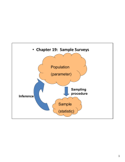
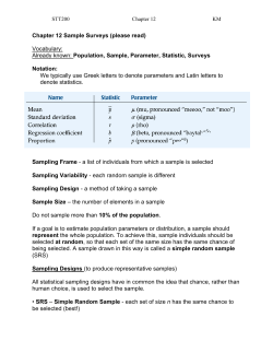


© Copyright 2026