
Texas Thermowell Thermowells, Protection Tubes, Sample Probes Catalog 4240 June 2008
Texas Thermowell
Thermowells, Protection Tubes, Sample Probes
Catalog 4240
June 2008
Catalog 4240
Introduction
Thermowells are recommended for temperature
instruments in process systems where pressure,
velocity, or viscous, abrasive, and corrosive
materials are present individually or in combination. A properly selected thermowell will protect
the temperature instrument from damage resulting from these process variables. Additionally, a
thermowell enables removal of the temperature
instrument for replacement, repair, or testing
without affecting the process system.
Table of Contents
2100 Series – Thermowells..................................1
2200 Series – Protection Tubes..........................11
2300 Series – Sample Probes............................15
Offer of Sale.......................................................20
Parker Texas Thermowell specializes in the design
and manufacture of all types of thermowells.
The 2100 Series thermowell designs shown in
this guide are styles that are popular throughout
industry. Special designs, as well as modifications
of our standard offerings, are also available.
Parker Texas Thermowell is dedicated to unsurpassed quality, on-time delivery, and competitive
pricing. This commitment has been recognized by
the International Standards Organization (ISO) –
our ISO 9001:2000 certification is additional
assurance to our customers that their buying
decisions can be made every day with a higher
level of supplier confidence, and affirms our
ongoing commitment to our quality policy –
“Parker Texas Thermowell will deliver
products, services and information that
meet or exceed customer requirements
and expectations every time.”
This product guide is intended to provide technical
data to deal with most applications. For severe
applications not adequately covered here, please
contact the factory for assistance.
WARNING
WARNING
Failure, improper selection or improper use of the products and/or systems described herein or related items can cause death, personal
injury and property damage.
This document and other information from Parker Hannifin Corporation, its subsidiaries and authorized distributors provide product and/or system options for further investigation by users
having technical expertise. It is important that you analyze all aspects of your application and review the information concerning the product or system in the current product catalog. Due
to the variety of operating conditions and applications for these products or systems, the user, through its own analysis and testing, is solely responsible for making the final selection of
the products and systems and assuring that all performance, safety and warning requirements of the application are met.
The products described herein, including without limitation, product features, specifications, designs, availability and pricing, are subject to change by Parker Hannifin Corporation and
its subsidiaries at any time without notice.
Offer of Sale
The items described in this document are hereby offered for sale by Parker Hannifin Corporation, its subsidiaries or its authorized distributors. This offer and its acceptance are governed
by the provisions stated in the “Offer of Sale”.
© Copyright 2008 Parker Hannifin Corporation. All Rights Reserved.
Parker Hannifin Corporation
Instrumentation Products Division
Beaumont, TX USA
http://www.parker.com/ipdus
Catalog 4240
2100 Series – Thermowells
2100 Series – Thermowells
Specifications
Manufacturing Standards
Materials
Bar Stock
Parker Texas Thermowell thermowells are
available in virtually any material to fit your
application. Contact the factory regarding
availability of materials not listed in the
“Ordering Information” guide on pages 4 and 5.
Mill Standard +0.000" to -1/32"
Shank O.D.
±0.010"
“U” Dimension
Strength
±0.050"
The strength of a thermowell depends on several
parameters that relate thermowell construction
to the installation environment. For most industrial
applications, standard Parker Texas Thermowell
thermowells provide the necessary strength if the
material, style, and length are correctly specified
for the application parameters: fluid type, temperature, pressure, and fluid velocity. It is important
to note that most thermowell failures are caused
by vibration that is induced by fluid flow.
Overall Length
±0.050"
Tip Thickness
1/4" ±0.050" (unless otherwise specified)
Shank Surface Finish
Polished to 16 RMS
In addition to providing this selection guide,
Parker Texas Thermowell offers assistance in
correctly selecting thermowells, given the
application parameters. This service is available
for a nominal charge. Contact the factory for more
information.
Bore
±0.003"
Construction
All 2100 Series thermowell bodies are machined
from solid bar stock. Flange mounts are welded
to the thermowell body. The serial number and
material are etched on each thermowell. Additional tagging for specific customer requirements
is available.
1
Parker Hannifin Corporation
Instrumentation Products Division
Beaumont, TX USA
http://www.parker.com/ipdus
Catalog 4240
2100 Series – Thermowells
Thermowell Terminology
Selection Considerations
Process Connection: External means to
connect thermowell to process system. Wells
can be threaded, bolted (to matching flange),
clamped, or welded in place.
Immersion Length (“U” Dimension)
For best temperature measurement accuracy, the
“U” dimension should be long enough to permit the
entire temperature-sensitive part of the measuring instrument to project into the medium being
measured.
Instrument Connection: Internal threads to connect temperature instrument to thermowell.
“U” Dimension: Length of thermowell immersed
into process system. Measured from the base
of the process connection to the end tip of the
well.
Liquid temperature measurement: A properly
designed thermowell will extend into the fluid an
amount equal to the length of the temperaturesensitive zone plus one inch or greater.
“T” Dimension: Also called “lag length” or “lagging extension.” Extends length between the
instrument and process connections to
accommodate vessel or piping insulation.
Gas temperature measurement: A properly
designed thermowell will extend into the fluid an
amount equal to the length of the temperaturesensitive zone plus three inches or greater.
“A” Dimension: Instrument insertion length into
thermowell. Equal to bore length.
The temperature-sensitive zone for thermocouples and thermistors is short (right at the tip
of the device), enabling measurement accuracy
with limited immersion into the process fluid.
“D” Dimension: Also called “tip diameter.”
Diameter of thermowell shank at the end tip
of the thermowell. This dimension may vary
with process connection and/or shank design.
Bi-metal thermometers, resistance temperature
detectors (RTDs), and liquid-in-glass thermometers have bulbs with temperature-sensitive zones
between one and two inches long.
“Q” Dimension: Also called “root diameter.”
Diameter of thermowell shank below the
process connection. This dimension may vary
with process connection and/or shank design.
Filled-system thermometer bulbs may have
temperature-sensitive zones from one to several
inches in length.
Bore Diameter: Dimension of internal bore to
match the diameter of the instrument inserted
into the thermowell.
Stepped Shank: Also called “reduced tip.” The
shank O.D. is reduced over the last 2-1/2"
of the “U” dimension from the standard root
diameter to 1/2" O.D. The stepped shank is
available with a 0.260" bore diameter only.
Bore Diameter
Straight Shank: Shank O.D. is the same from
the root diameter (“Q” dimension) to the tip
diameter (“D” dimension). The straight shank
is generally used with a 0.385" or larger bore
diameter, but is also available with a 0.260"
bore.
0.260" bore:
Bi-metal Thermometers (1/4" stem)
Thermocouples (1/4" sheath)
RTDs (1/4" sheath)
Liquid-in-glass Test Thermometers (unarmored)
Other elements having 0.252" maximum diameter
Tapered Shank: Shank O.D. is gradually reduced
from the root diameter (“Q” dimension)
to the tip diameter (“D” dimension). The
tapered shank is recommended for heavy
duty applications characterized by high
vibration, pressure, temperature, and/or
velocity.
0.385" bore:
Bi-metal Thermometers (3/8" stem)
Thermocouples (8 and 14 gage)
Liquid-in-glass Test Thermometers (armored)
Other elements having 0.377" maximum diameter
While Parker Texas Thermowell offers thermowells with bore diameters up to 0.718", the most
common are as follows:
2
Parker Hannifin Corporation
Instrumentation Products Division
Beaumont, TX USA
http://www.parker.com/ipdus
Catalog 4240
2100 Series – Thermowells
natural frequency of the well were to coincide
with the wake frequency, the well would vibrate to
destruction and break off.
Shank Style
Tapered shank wells provide greater stiffness for
the same sensitivity. The higher strength to weight
ratio gives these wells higher natural frequency
than for equivalent straight shank wells, thus permitting operation at higher fluid velocities.
Table 1 provides recommended maximum velocity
ratings for common well length and material combinations. To reduce the complexity of presenting this information, the ratings given are based
on operating temperatures of 1000°F for carbon
steel, 304 SST, and 316 SST wells. Ratings for
brass wells are based on 350°F service. Ratings
for Monel wells are based on 900°F service.
Slightly higher velocity is possible at lower
temperatures.
Velocity Ratings
In most cases, thermowell failures are not due
to the effects of pressure and temperature. The
calculations necessary to provide adequate
strength under given conditions are familiar
enough to permit proper choice of wall thickness
and material.
The velocity ratings provided are extremely
conservative and intended primarily as a guide.
Wells are safe from vibrational destruction if the
resonant frequency is well below the wake
frequency, or if the fluid velocity is constantly
fluctuating through the critical velocity point.
Nevertheless, if the installation is not hampered
by a sufficiently stiff well, it is recommended that
the values given not be exceeded.
Less familiar are the vibrational effects to which
thermowells are subjected. Fluid flowing past
the well forms a turbulent wake (the Von Karman
Trail), which has a definite frequency based on
the diameter of the well and the velocity of the
fluid. The thermowell must have sufficient stiffness
so that the wake frequency will never equal the
natural frequency of the thermowell itself. If the
Table 1. Maximum Fluid Velocity Ratings (ft/sec)
Shank
Style
Root Dia.
“Q” Dim.
Material
Brass
Carbon Steel
3/4"
304, 316 SST
Monel
Stepped
Brass
Carbon Steel
7/8"
304, 316 SST
Monel
Brass
Carbon Steel
Straight
Any
304, 316 SST
Monel
Carbon Steel
Tapered
Any
304, 316 SST
Monel
Process
Fluid
Liquid
Gas
Liquid
Gas
Liquid
Gas
Liquid
Gas
Liquid
Gas
Liquid
Gas
Liquid
Gas
Liquid
Gas
Liquid
Gas
Liquid
Gas
Liquid
Gas
Liquid
Gas
Liquid
Gas
Liquid
Gas
Liquid
Gas
2-1/2"
59.3
207
106
290
148
300
118
261
59.3
207
106
290
148
300
118
261
145
290
260
326
360
349
316
320
270
410
350
483
300
396
4-1/2"
39.8
89.1
71.2
123
99.3
128
79.8
112
47.6
102
84.3
143
117
148
93.3
128
80
150
144
192
199
178
189
150
249
208
272
167
214
3
Immersion Length – “U” Dimension
7-1/2"
10-1/2"
13-1/2"
16-1/2"
23.9
16.4
9.9
6.6
32.3
42.7
22.8
13.8
9.3
44.9
19-1/2"
22-1/2"
4.8
3.6
6.7
4.9
46.4
23.6
14.3
9.6
6.9
5.1
40.6
20.7
12.4
8.3
6.1
4.5
18.8
11.4
7.6
5.5
4.1
26.2
15.9
10.6
7.6
5.7
53.5
27.2
16.5
11.0
7.9
5.9
46.7
23.7
14.4
9.5
6.9
5.1
48.0
54.1
27.6
16.7
11.1
8.0
6.0
69.5
35.4
20.5
14.3
10.3
7.7
71.9
36.6
21.2
14.8
10.7
8.0
68.1
34.8
20.8
14.0
10.0
7.5
90.3
45.6
27.8
18.5
13.2
9.8
97.3
49.7
30.4
20.3
14.5
10.7
77.5
39.2
23.8
16.0
10.3
7.7
37.0
28.0
51.6
50.6
Parker Hannifin Corporation
Instrumentation Products Division
Beaumont, TX USA
http://www.parker.com/ipdus
Catalog 4240
2100 Series – Thermowells
Ordering Information
Example Model Number: 2100A105F43A030ARE-04-07-11
Series
Material
Immersion
Length
(“U” Dim.)
Mounting
Style
2100
A
105
F43
Material
304 SST
310 SST
316 SST
321 SST
Alloy 20
Carbon Steel
Hastelloy C
Hastelloy B
Inconel 600
Monel
Nickel 200
Titanium
Brass
Other
(please specify)
Mounting
Style
Code
A
C
D
F
G
H
J
K
M
P
T
W
Y
Shank
Style
Stepped
Threaded
Straight
Tapered
Stepped
Flanged
Straight
X
Length (“U”)
(in inches)
1.625
2.0
2.5
3.0
3.5
4.0
4.5
5.0
5.5
6.0
6.5
7.0
7.5
8.0
8.5
9.0
9.5
10.0
Process
Connection
1/2" NPT
3/4" NPT
1" NPT
1-1/2" NPT
1/2" NPT
3/4" NPT
1" NPT
1-1/2" NPT
1/2" NPT
3/4" NPT
1" NPT
1-1/2" NPT
1", Class 150
1-1/2", Class 150
2", Class 150
1", Class 300
1-1/2", Class 300
2", Class 300
1", Class 600
1-1/2", Class 600
2", Class 600
1", Class 150
1-1/2", Class 150
2", Class 150
1", Class 300
1-1/2", Class 300
2", Class 300
1", Class 600
1-1/2", Class 600
2", Class 600
Code
T21
T22
T23
T24
T31
T32
T33
T34
T41
T42
T43
T44
F21
F22
F23
F24
F25
F26
F27
F28
F29
F31
F32
F33
F34
F35
F36
F37
F38
F39
Code
016
020
025
030
035
040
045
050
055
060
065
070
075
080
085
090
095
100
Length (“U”)
(in inches)
10.5
11.0
11.5
12.0
12.5
13.0
13.5
14.0
14.5
15.0
15.5
16.0
16.5
17.0
17.5
18.0
18.5
Mounting
Style
Flanged
Shank
Style
Tapered
Stepped
Van
Stone
Straight
Tapered
Code
105
110
115
120
125
130
135
140
145
150
155
160
165
170
175
180
185
Length (“U”)
(in inches)
19.0
19.5
20.0
20.5
21.0
21.5
22.0
22.5
23.0
24.0
25.0
26.0
27.0
28.0
29.0
30.0
31.0
Process
Connection
1", Class 150
1-1/2", Class 150
2", Class 150
1", Class 300
1-1/2", Class 300
2", Class 300
1", Class 600
1-1/2", Class 600
2", Class 600
1",
Class 900/1500
1-1/2",
Class 900/1500
2",
Class 900/1500
1", Class 2500
1-1/2", Class 2500
2", Class 2500
1"
1-1/2"
2"
1"
1-1/2"
2"
1"
1-1/2"
2"
4
Code
F41
F42
F43
F44
F45
F46
F47
F48
F49
F51
Code
190
195
200
205
210
215
220
225
230
240
250
260
270
280
290
300
310
Length (“U”)
(in inches)
32.0
33.0
34.0
35.0
36.0
37.0
38.0
39.0
40.0
41.0
42.0
43.0
44.0
45.0
46.0
47.0
48.0
Mounting
Style
Shank
Style
Stepped
Socket
Weld
Straight
Tapered
Weld-In
Tapered
F52
F53
F54
F55
F56
V21
V22
V23
V31
V32
V33
V41
V42
V43
Stepped
Sanitary
Straight
Tapered
Other
(please
specify)
(Continued on the
following page)
Code
320
330
340
350
360
370
380
390
400
410
420
430
440
450
460
470
480
Process
Connection
3/4" pipe
1" pipe
3/4" pipe
1" pipe
3/4" pipe
1" pipe
1-1/2" pipe
3/4" pipe
(1.05" O.D.)
1" pipe
(1.32" O.D.)
1-1/2" pipe
(1.9" O.D.)
1-1/2" Tri-Clamp
2" Tri-Clamp
2-1/2" Tri-Clamp
3" Tri-Clamp
1-1/2" Tri-Clamp
2" Tri-Clamp
2-1/2" Tri-Clamp
3" Tri-Clamp
1-1/2" Tri-Clamp
2" Tri-Clamp
2-1/2" Tri-Clamp
3" Tri-Clamp
(please
specify)
Code
K21
K22
K31
K32
K41
K42
K43
W41
W42
W43
S21
S22
S23
S24
S31
S32
S33
S34
S41
S42
S43
S44
XXX
Parker Hannifin Corporation
Instrumentation Products Division
Beaumont, TX USA
http://www.parker.com/ipdus
Catalog 4240
2100 Series – Thermowells
(Continued from the
previous page)
Bore
Diameter
0.260"
0.385"
0.437"
0.515"
0.656"
0.718"
Other
(please specify)
Code
A
B
C
D
E
F
X
Bore
Diameter
Lag Length
(“T” Dim.)
Instrument
Connection
Root
Diameter
(“Q” Dim.)
Tip
Diameter
(“D” Dim.)
A
030
A
R
E
Length (“T”)
(in inches)
Code
0.0
000
0.5
005
1.0
010
1.5
015
2.0
020
2.5
025
3.0
030
3.5
035
4.0
040
4.5
045
5.0
050
5.5
055
6.0
060
6.5
065
7.0
070
7.5
075
8.0
080
8.5
085
9.0
090
9.5
095
Other
XXX
(please specify)
Instrument
Connection
Thread
1/2" NPT
1/2" NPSM
1/4" NPT
3/4" NPT
3/4" NPSM
1" NPT
1" NPSM
Other
(please specify)
Code
A
B
C
D
E
F
G
X
Option
Thermowell material certificate
Diameter
(“Q”)
(in inches)
0.375
0.400
0.500
0.562
0.625
0.680
0.735
0.750
0.766
0.781
0.860
0.875
0.900
1.000
1.050
1.063
1.125
1.250
1.315
1.375
1.500
1.625
1.900
Other
Diameter
(“D”)
(in inches)
0.375
0.400
0.500
0.562
0.625
0.680
0.735
0.750
0.766
0.781
0.860
0.875
0.900
1.000
1.050
1.063
1.125
1.250
1.315
1.375
1.500
1.625
1.900
Other
Code
A
B
C
D
E
F
G
H
J
K
L
M
N
P
Q
R
S
T
U
V
W
Y
Z
X
Options
-04
-07
-11
Code
A
B
C
D
E
F
G
H
J
K
L
M
N
P
Q
R
S
T
U
V
W
Y
Z
X
Code
Option
Code
-01
Concentric serrations of thermowell flange face
-12*
Flat face flange
-13*
Ring Joint flange
-14*
Thermowell special surface finish (12Ra Max)
-15
Special stamping
-17
Thermowell Wake Frequency Calculation
(Configuration Data Sheet Required)
-02
Thermowell special internal pressure testing
-03
Thermowell special external pressure testing
-04(1)
Thermowell dye penetration testing
-05
Plug and chain – stainless steel
-18
Special cleaning for oxygen service
-06
Plug and chain – brass
-19
NACE MR-01-75 approval
-07
Teflon coating
-20
Electropolishing
-08
Weldment X-Ray
-21
Stellite overlay
-09
Tantalum sheath
-22*
Chrome plating
-10
Titantium sheath
-23*
Full penetration weld
-11*
Positive Material Identification (PMI) test
-24
* Available on flanged thermowells only. Only one flange face option allowed.
5
Parker Hannifin Corporation
Instrumentation Products Division
Beaumont, TX USA
http://www.parker.com/ipdus
Catalog 4240
2100 Series – Thermowells
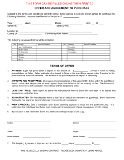
Figure 1. Threaded Thermowells
Stepped
Straight
Tapered
Limited Space Thermowell
6
Parker Hannifin Corporation
Instrumentation Products Division
Beaumont, TX USA
http://www.parker.com/ipdus
Catalog 4240
2100 Series – Thermowells
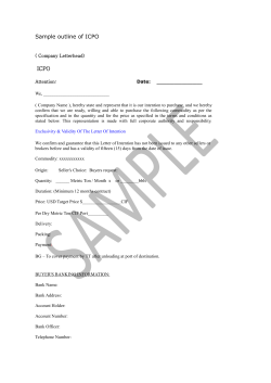
Figure 2. Flanged Thermowells
Stepped
Straight
Tapered
7
Parker Hannifin Corporation
Instrumentation Products Division
Beaumont, TX USA
http://www.parker.com/ipdus
Catalog 4240
2100 Series – Thermowells
Figure 3. Van Stone Thermowells
Stepped
Size
Head Diameter
(in inches) “C” (in inches)
1
1.315
1-1/2
1.900
2
2.375
Straight
Size
Head Diameter
(in inches) “C” (in inches)
1
1.315
1-1/2
1.900
2
2.375
Tapered
Size
Head Diameter
(in inches) “C” (in inches)
1
1.315
1-1/2
1.900
2
2.375
8
Parker Hannifin Corporation
Instrumentation Products Division
Beaumont, TX USA
http://www.parker.com/ipdus
Catalog 4240
2100 Series – Thermowells
Figure 4. Socket Weld Thermowells
Stepped
Size
Head Diameter
(in inches) “C” (in inches)
3/4
1.050
1
1.315
1-1/2
1.900
Straight
Size
Head Diameter
(in inches) “C” (in inches)
3/4
1.050
1
1.315
1-1/2
1.900
Tapered
Size
Head Diameter
(in inches) “C” (in inches)
3/4
1.050
1
1.315
1-1/2
1.900
9
Parker Hannifin Corporation
Instrumentation Products Division
Beaumont, TX USA
http://www.parker.com/ipdus
Catalog 4240
2100 Series – Thermowells
Figure 5. Sanitary Thermowells
Stepped
Straight
Tapered
Figure 6. Weld-InThermowells
Tapered
Size
Head Diameter
(in inches) “C” (in inches)
3/4
1.050
1
1.315
1-1/2
1.900
10
Parker Hannifin Corporation
Instrumentation Products Division
Beaumont, TX USA
http://www.parker.com/ipdus
Catalog 4240
2200 Series – Protection Tubes
2200 Series – Protection Tubes
Manufacturing Standards
Terminology
Material
Process Connection: External means to
connect protection tube to process system.
Tubes can be threaded, bolted (to matching
flange), or welded in place.
In compliance with ASTM specifications or other
applicable national standard (i.e., ASME, AWS,
etc.)
Instrument Connection: Means to connect
temperature instrument to protection tube.
Typically male pipe threaded.
Process Connection
Flange:
In compliance with ANSI B16.5 prior to
fabrication
“U” Dimension: Length of protection tube
immersed into process system. Measured
from the base of the process connection to
the end tip of the tube.
Bushing: Welded in place
Welded: Bare tube
“H” Dimension: Also called “head length.”
Measured from the base of the process
connection to the face of the instrument
connection.
Instrument Connection
Male pipe thread in compliance with ANSI
B1.20.1-92
“A” Dimension: Instrument insertion length into
protection tube.
“U” Dimension
±0.50" for immersion lengths <60"
±0.75" for immersion lengths 60" to 96"
±1.00" for immersion lengths >96"
Tip Thickness
1/4" ±0.050 (unless otherwise specified)
Welding
Flange to Base Metal:
per Parker Texas Thermowell Dwg. TX-A1
Bushing to Base Metal:
Fillet weld
Barstock for Closed-end:
per Parker Texas Thermowell dwg no.
TX-FP-TIP(1)
Pipe Cap for Closed-end:
per Parker Texas Thermowell dwg no. TX-B(1)
(1) Full penetration weld locations are subject to minor
distortion and internal filler metal slag.
11
Parker Hannifin Corporation
Instrumentation Products Division
Beaumont, TX USA
http://www.parker.com/ipdus
Catalog 4240
2200 Series – Protection Tubes
Ordering Information
Example Model Number: 2200A240E09A030A-01-07-11
Series
Material
Immersion
Length
(“U” Dim.)
Tube
Style
2200
A
240
E
Material
304 SST
310 SST
316 SST
321 SST
Alloy 20
Carbon Steel
Hastelloy C
Hastelloy B
Inconel 600
Monel
Nickel 200
Titanium
Brass
Other
(please specify)
Code
A
C
D
F
G
H
J
K
M
P
T
W
Y
X
Length (“U”)
(in inches)
12
15
18
21
24
27
30
32
34
36
38
40
42
44
46
48
50
52
54
56
58
60
62
64
66
68
70
72
74
76
78
80
82
84
86
88
90
92
94
96
98
Other (please
specify)
12
Code
120
150
180
210
240
270
300
320
340
360
380
400
420
440
460
480
500
520
540
560
580
600
620
640
660
680
700
720
740
760
780
800
820
840
860
880
900
920
940
960
980
Tube
Style
Size
1/2" O.D.
5/8" O.D.
3/4" O.D.
7/8" O.D.
1" O.D.
1-1/8" O.D.
1-1/4" O.D.
Drilled
Barstock
Tube
Style
(Continued on the
following page)
Size
1/4"
1/2"
Pipe
3/4"
1"
Schedule
40
80
160
XX Heavy
40
80
160
XX Heavy
40
80
160
XX Heavy
40
80
160
XX Heavy
Code
A
B
C
D
E
F
G
Code
H
J
K
L
M
N
P
Q
R
T
U
V
W
X
Y
Z
XXX
Parker Hannifin Corporation
Instrumentation Products Division
Beaumont, TX USA
http://www.parker.com/ipdus
Catalog 4240
2200 Series – Protection Tubes
(Continued from the
previous page)
Process
Connection
3/4" NPT
1" NPT
1-1/2" NPT
2" NPT
Welded
1", Class 150
1-1/2", Class 150
2", Class 150
3", Class 150
4", Class 150
1", Class 300
1-1/2", Class 300
2", Class 300
3", Class 300
4", Class 300
1", Class 600
1-1/2", Class 600
2", Class 600
3", Class 600
4", Class 600
Other
(please specify)
Process
Connection
Bore
Diameter
Head Length
“H” Dim.
Instrument
Connection
09
A
030
A
Code
01
02
03
04
05
06
07
08
09
10
11
12
13
14
15
16
17
18
19
20
Bore
Diameter
Length (“H”)
in inches*
2.0
2.5
3.0
3.5
4.0
4.5
5.0
5.5
6.0
6.5
7.0
7.5
8.0
8.5
9.0
9.5
Other
(please specify)
Code
0.260"
0.385"
N/A
(Pipe Construction)
Other
(please specify)
A
B
P
X
Code
020
025
030
035
040
045
050
055
060
065
070
075
080
085
090
095
Instrument
Connection
Thread
1/2-14 NPT
1/2-14 NPSM
Other
(please specify)
Options
-01
-07
-11
Code
A
B
X
XXX
XX
Option
Thermowell material certificate
Code
Option
Code
-01
Concentric serrations of thermowell flange face
-12*
Flat face flange
-13*
Ring Joint flange
-14*
Thermowell Wake Frequency Calculation
(Configuration Data Sheet Required)
-02
Thermowell special internal pressure testing
-03
Thermowell special surface finish (12Ra Max)
-15
Thermowell special external pressure testing
-04*
Special stamping
-17
Thermowell dye penetration testing
-05
Plug and chain – stainless steel
-18
Special cleaning for oxygen service
-06
Plug and chain – brass
-19
NACE MR-01-75 approval
-07
Teflon coating
-20
Electropolishing
-08
Weldment X-Ray
-21
Stellite overlay
-09
Tantalum sheath
-22*
Chrome plating
-10
Titantium sheath
-23*
Full penetration weld
-11*
Positive Material Identification (PMI) test
-24
* Available on flanged thermowells only. Only one flange face option allowed.
13
Parker Hannifin Corporation
Instrumentation Products Division
Beaumont, TX USA
http://www.parker.com/ipdus
2200 Series – Protection Tubes
Catalog 4240
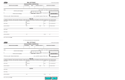
Figure 7. Drilled Barstock Protection Tubes
Threaded (Bushing)
Flanged
Weld-In
14
Parker Hannifin Corporation
Instrumentation Products Division
Beaumont, TX USA
http://www.parker.com/ipdus
Catalog 4240
2300 Series – Sample Probes
2300 Series – Sample Probes
Manufacturing Standards
Bar Stock
Overall Length
Mill Standard +0.000" / -1/32"
±0.050"
Shank O.D.
Shank Surface Finish
±0.010"
Polished to 16 RMS
“U” Dimension
Bore
±0.050"
±0.003"
Figure 8. Sample Probes
Threaded
Flanged
15
Parker Hannifin Corporation
Instrumentation Products Division
Beaumont, TX USA
http://www.parker.com/ipdus
Catalog 4240
2300 Series – Sample Probes
Ordering Information
Example Model Number: 2300A070T21A000AH-01-08
Series
Material
Immersion
Length
“U” Dim.
Process
Connection
2300
A
070
T21
Material
304 SST
310 SST
316 SST
321 SST
Alloy 20
Carbon Steel
Hastelloy C
Hastelloy B
Inconel 600
Monel
Nickel 200
Titanium
Brass
Other
(please specify)
Mounting
Style
Code
A
C
D
F
G
H
J
K
M
P
T
W
Y
Threaded
Flanged
Other
Process
Connection
1/2" NPT
3/4" NPT
1" NPT
1", Class 150
1-1/2", Class 150
2", Class 150
1", Class 300
1-1/2", Class 300
2", Class 300
1", Class 600
1-1/2", Class 600
2", Class 600
(please specify)
(Continued on the
following page)
Code
T31
T32
T33
F31
F32
F33
F34
F35
F36
F37
F38
F39
XXX
X
Length (“U”)
(in inches)
1.5
2.0
2.5
3.0
3.5
4.0
4.5
5.0
5.5
6.0
6.5
7.0
7.5
8.0
8.5
9.0
9.5
10.0
10.5
11.0
11.5
12.0
12.5
Code
015
020
025
030
035
040
045
050
055
060
065
070
075
080
085
090
095
100
105
110
115
120
125
Length (“U”)
(in inches)
13.0
13.5
14.0
14.5
15.0
15.5
16.0
16.5
17.0
17.5
18.0
18.5
19.0
19.5
20.0
20.5
21.0
21.5
22.0
22.5
23.0
24.0
25.0
16
Code
130
135
140
145
150
155
160
165
170
175
180
185
190
195
200
205
210
215
220
225
230
240
250
Length (“U”)
(in inches)
26.0
27.0
28.0
29.0
30.0
31.0
32.0
33.0
34.0
35.0
36.0
37.0
38.0
39.0
40.0
41.0
42.0
43.0
44.0
45.0
46.0
47.0
48.0
Code
260
270
280
290
300
310
320
330
340
350
360
370
380
390
400
410
420
430
440
450
460
470
480
Parker Hannifin Corporation
Instrumentation Products Division
Beaumont, TX USA
http://www.parker.com/ipdus
Catalog 4240
(Continued from the
previous page)
Bore
Diameter
0.260"
0.385"
Other
(please specify)
2300 Series – Sample Probes
Bore
Diameter
Lag Length
(“T” Dim.)
Sampler
Connection
Shank
Length
(“D” Dim.)
A
030
A
H
Code
A
B
X
Length (“T”)
(in inches)
0.0
0.5
1.0
1.5
2.0
2.5
3.0
3.5
4.0
4.5
5.0
5.5
6.0
6.5
7.0
7.5
8.0
8.5
9.0
9.5
Other
(please specify)
Instrument
Connection
Thread
1/2-14 ANPT
1/2-14 NPSM
Other
(please specify)
Code
000
005
010
015
020
025
030
035
040
045
050
055
060
065
070
075
080
085
090
095
Code
A
B
X
XXX
Diameter (“D”)
(in inches)
0.375
0.400
0.500
0.562
0.625
0.680
0.735
0.750
0.766
0.781
0.860
0.875
0.900
1.000
1.050
1.063
1.125
1.250
1.315
1.375
1.500
1.625
1.900
Other
(please specify)
Options
-01
-08
Code
A
B
C
D
E
F
G
H
J
K
L
M
N
P
Q
R
S
T
U
V
W
Y
Z
X
Option
Code
Thermowell material certificate
-01
Thermowell Wake Frequency Calculation
(Configuration Data Sheet Required)
-02
NACE MR-01-75 approval
-07
Electropolishing
-08
Full penetration weld
-11*
Concentric serrations of thermowell flange face
-12*
Flat face flange
-13*
Ring Joint flange
-14*
Thermowell special surface finish (12Ra Max)
-15
Special stamping
-17
Weldment X-Ray
-21
Positive Material Identification (PMI) test
-24
* Available on flanged thermowells only. Only one flange face
option allowed.
17
Parker Hannifin Corporation
Instrumentation Products Division
Beaumont, TX USA
http://www.parker.com/ipdus
Catalog 4240
Notes
18
Parker Hannifin Corporation
Instrumentation Products Division
Beaumont, TX USA
http://www.parker.com/ipdus
Catalog 4240
Notes
19
Parker Hannifin Corporation
Instrumentation Products Division
Beaumont, TX USA
http://www.parker.com/ipdus
Catalog 4240
Offer of Sale
The items described in this document and other documents or descriptions provided by Parker Hannifin Corporation, its subsidiaries and its authorized distributors are hereby offered for sale at prices to be established by Parker Hannifin Corporation, its subsidiaries and its authorized distributors.
This offer and its acceptance by any customer ("Buyer") shall be governed by all of the following Terms and Conditions. Buyer’s order for any such
items, when communicated to Parker Hannifin Corporation, its subsidiary or an authorized distributor ("Seller") verbally or in writing, shall constitute
acceptance of this offer.
1. Terms and Conditions of Sale: All descriptions, quotations, proposals,
offers, acknowledgments, acceptances and sales of Seller’s products are
subject to and shall be governed exclusively by the terms and conditions
stated herein. Buyer’s acceptance of any offer to sell is limited to these terms
and conditions. Any terms or conditions in addition to, or inconsistent with
those stated herein, proposed by Buyer in any acceptance of an offer by
Seller, are hereby objected to. No such additional, different or inconsistent
terms and conditions shall become part of the contract between Buyer and
Seller unless expressly accepted in writing by Seller. Seller’s acceptance
of any offer to purchase by Buyer is expressly conditional upon Buyer’s
assent to all the terms and conditions stated herein, including any terms in
addition to, or inconsistent with those contained in Buyer’s offer, Acceptance
of Seller’s products shall in all events constitute such assent.
2. Payment: Payment shall be made by Buyer net 30 days from the date
of delivery of the items purchased hereunder. Amounts not timely paid
shall bear interest at the maximum rate permitted by law for each month
or portion thereof that the Buyer is late in making payment. Any claims
by Buyer for omissions or shortages in a shipment shall be waived unless
Seller receives notice thereof within 30 days after Buyer’s receipt of the
shipment.
3. Delivery: Unless otherwise provided on the face hereof, delivery shall
be made F.O.B. Seller’s plant. Regardless of the method of delivery, however, risk of loss shall pass to Buyer upon Seller’s delivery to a carrier. Any
delivery dates shown are approximate only and Seller shall have no liability
for any delays in delivery.
4. Warranty: Seller warrants that items sold hereunder shall be free
from defects in material or workmanship. THIS WARRANTY COMPRISES
THE SOLE AND ENTIRE WARRANTY PERTAINING TO ITEMS
PROVIDED HEREUNDER. SELLER MAKES NO OTHER WARRANTY,
GUARANTEE, OR REPRESENTATION OF ANY KIND WHATSOEVER.
ALL OTHER WARRANTIES, INCLUDING BUT NOT LIMITED TO,
MERCHANTABILITY AND FITNESS FOR PURPOSE, WHETHER
EXPRESS, IMPLIED, OR ARISING BY OPERATION OF LAW, TRADE
USAGE, OR COURSE OF DEALING ARE HEREBY DISCLAIMED.
NOTWITHSTANDING THE FOREGOING, THERE ARE NO WARRAN
TIES WHATSOEVER ON ITEMS BUILT OR ACQUIRED WHOLLY OR
PARTIALLY, TO BUYER’S DESIGNS OR SPECIFICATIONS.
5. Limitation Of Remedy: SELLER’S LIABILITY ARISING FROM OR IN
ANY WAY CONNECTED WITH THE ITEMS SOLD OR THIS CONTRACT
SHALL BE LIMITED EXCLUSIVELY TO REPAIR OR REPLACEMENT
OF THE ITEMS SOLD, AT SELLER’S SOLE OPTION. IN NO EVENT
SHALL SELLER BE LIABLE FOR ANY INCIDENTAL, CONSEQUENTIAL
OR SPECIAL DAMAGES OF ANY KIND OR NATURE WHATSOEVER,
INCLUDING BUT NOT LIMITED TO LOST PROFITS ARISING FROM
OR IN ANY WAY CONNECTED WITH THIS AGREEMENT OR ITEMS
SOLD HEREUNDER, WHETHER ALLEGED TO ARISE FROM BREACH
OF CONTRACT, EXPRESS OR IMPLIED WARRANTY, OR IN TORT,
INCLUDING WITHOUT LIMITATION, NEGLIGENCE, FAILURE TO
WARN OR STRICT LIABILITY.
6. Changes, Reschedules and Cancellations: Buyer may request to
modify the designs or specifications for the items sold hereunder as well
as the quantities and delivery dates thereof, or may request to cancel all
or part of this order, however, no such requested modification or cancellation
shall become part of the contract between Buyer and Seller unless accepted
by Seller in a written amendment to this Agreement. Acceptance of any
such requested modification or cancellation shall be at Seller’s discretion,
and shall be upon such terms and conditions as Seller may require.
7. Special Tooling: A tooling charge may be imposed for any special
tooling, including without limitation, dies, fixtures, molds and patterns,
acquired to manufacture items sold pursuant to this contract. Such special
tooling shall be and remain Seller’s property notwithstanding payment of
any charges by Buyer. In no event will Buyer acquire any interest in apparatus belonging to Seller which is utilized in the manufacture of the items
sold hereunder, even if such apparatus has been specially converted or
adapted for such manufacture and not withstanding any charges paid by
Buyer. Unless otherwise agreed, Seller shall have the right to alter, discard
or otherwise dispose of any special tooling or other property in its sole
discretion at any time.
8. Buyer’s Property: Any designs, tools, patterns, materials, drawings,
confidential information or equipment furnished by Buyer or any other
items which become Buyer’s property, may be considered obsolete and
may be destroyed by Seller after two (2) consecutive years have elapsed
without Buyer placing an order for the items which are manufactured using
such property, Seller shall not be responsible for any loss or damage to
such property while it is in Seller’s possession or control.
9. Taxes: Unless otherwise indicated on the face hereof, all prices and
charges are exclusive of excise, sales, use, property, occupational or like
taxes which may be imposed by any taxing authority upon the manufacture, sale or delivery of the items sold hereunder. If any such taxes must be
paid by Seller or if Seller is liable for the collection of such tax, the amount
thereof shall be in addition to the amounts for the items sold. Buyer
agrees to pay all such taxes or to reimburse Seller therefore upon receipt
of its invoice. If Buyer claims exemption from any sales, use or other tax
imposed by any taxing authority, Buyer shall save Seller harmless from
and against any such tax, together with any interest or penalties thereon
which may be assessed if the items are held to be taxable.
10. Indemnity For Infringement of Intellectual Property Rights: Seller
shall have no liability for infringement of any patents, trademarks, copyrights, trade dress, trade secrets or similar rights except as provided in
this Part 10. Seller will defend and indemnify Buyer against allegations of
infringement of U.S. Patents, U.S. Trademarks, copyrights, trade dress and
trade secrets (hereinafter ‘Intellectual Property Rights’). Seller will defend
at its expense and will pay the cost of any settlement or damages awarded
in an action brought against Buyer based on an allegation that an item
sold pursuant to this contract infringes the Intellectual Property Rights of a
third party. Seller’s obligation to defend and indemnify Buyer is contingent
on Buyer notifying Seller within ten (10) days after Buyer becomes aware
of such allegations of infringement, and Seller having sole control over the
defense of any allegations or actions including all negotiations for settlement or compromise. If an item sold hereunder is subject to a claim that it
infringes the Intellectual Property Rights of a third party, Seller may, at its
sole expense and option, procure for Buyer the right to continue using said
item, replace or modify said item so as to make it noninfringing, or offer
to accept return of said item and return the purchase price less a reasonable allowance for depreciation. Notwithstanding the foregoing, Seller shall
have no liability for claims of infringement based on information provided
by Buyer, or directed to items delivered hereunder for which the designs
are specified in whole or part by Buyer, or infringements resulting from the
modification, combination or use in a system of any item sold hereunder.
The foregoing provisions of this Part 10 shall constitute Seller’s sole and
exclusive liability and Buyer’s sole and exclusive remedy for infringement
of Intellectual Property Rights.
If a claim is based on information provided by Buyer or if the design for an
item delivered hereunder is specified in whole or in part by Buyer, Buyer
shall defend and indemnify Seller for all costs, expenses or judgments
resulting from any claim that such item infringes any patent, trademark,
copyright, trade dress, trade secret or any similar right.
11. Force Majeure: Seller does not assume the risk of and shall not be
liable for delay or failure to perform any of Seller’s obligations by reason
of circumstances beyond the reasonable control of Seller (hereinafter
‘Events of Force Majeure’). Events of Force Majeure shall include without
limitation, accidents, acts of God, strikes or labor disputes, acts, laws, rules
or regulations of any government or government agency, fires, floods,
delays or failures in delivery of carriers or suppliers, shortages of materials
and any other cause beyond Seller’s control.
12. Entire Agreement/Governing Law: The terms and conditions set
forth herein, together with any amendments, modifications and any different terms or conditions expressly accepted by Seller in writing, shall
constitute the entire Agreement concerning the items sold, and there are
no oral or other representations or agreements which pertain thereto. This
Agreement shall be governed in all respects by the law of the State of
Ohio. No actions arising out of the sale of the items sold hereunder or this
Agreement may be brought by either party more than two (2) years after
the cause of action accrues.
20
11/98-P
Parker Hannifin Corporation
Instrumentation Products Division
Beaumont, TX USA
http://www.parker.com/ipdus
Parker’s Motion & Control Technologies
At Parker, we’re guided by
a relentless drive to help
our customers become more
productive and achieve
higher levels of profitability by engineering the best
systems for their requirements. It means looking at
customer applications from
many angles to find new
ways to create value. Whatever the motion and control
technology need, Parker has
the experience, breadth of
product and global reach
to consistently deliver. No
company knows more about
motion and control technology than Parker. For further
info call 1-800-C-Parker.
AEROSPACE
Key Markets
• Aircraft engines
• Business & general aviation
• Commercial transports
• Land-based weapons systems
• Military aircraft
• Missiles & launch vehicles
• Regional transports
• Unmanned aerial vehicles
Key Products
• Flight control systems
& components
• Fluid conveyance systems
• Fluid metering delivery
& atomization devices
• Fuel systems & components
• Hydraulic systems & components
• Inert nitrogen generating systems
• Pneumatic systems & components
• Wheels & brakes
FLUID & GAS HANDLING
Key Markets
• Aerospace
• Agriculture
• Bulk chemical handling
• Construction machinery
• Food & beverage
• Fuel & gas delivery
• Industrial machinery
• Mobile
• Oil & gas
• Transportation
• Welding
HYDRAULICS
Key Markets
• Aerospace
• Aerial lift
• Agriculture
• Construction machinery
• Forestry
• Industrial machinery
• Mining
• Oil & gas
• Power generation & energy
• Truck hydraulics
Key Products
• Brass fittings & valves
• Diagnostic equipment
• Fluid conveyance systems
• Industrial hose
• PTFE & PFA hose, tubing &
plastic fittings
• Rubber & thermoplastic hose
& couplings
• Tube fittings & adapters
• Quick disconnects
Key Products
• Diagnostic equipment
• Hydraulic cylinders
& accumulators
• Hydraulic motors & pumps
• Hydraulic systems
• Hydraulic valves & controls
• Power take-offs
• Rubber & thermoplastic hose
& couplings
• Tube fittings & adapters
• Quick disconnects
CLIMATE CONTROL
Key Markets
• Agriculture
• Air conditioning
• Food, beverage & dairy
• Life sciences & medical
• Precision cooling
• Processing
• Transportation
Key Products
• CO2 controls
• Electronic controllers
• Filter driers
• Hand shut-off valves
• Hose & fittings
• Pressure regulating valves
• Refrigerant distributors
• Safety relief valves
• Solenoid valves
• Thermostatic expansion valves
PNEUMATICS
Key Markets
• Aerospace
• Conveyor & material handling
• Factory automation
• Life science & medical
• Machine tools
• Packaging machinery
• Transportation & automotive
Key Products
• Air preparation
• Brass fittings & valves
• Manifolds
• Pneumatic accessories
• Pneumatic actuators & grippers
• Pneumatic valves & controls
• Quick disconnects
• Rotary actuators
• Rubber & thermoplastic hose
& couplings
• Structural extrusions
• Thermoplastic tubing & fittings
• Vacuum generators, cups & sensors
ELECTROMECHANICAL
Key Markets
• Aerospace
• Factory automation
• Life science & medical
• Machine tools
• Packaging machinery
• Paper machinery
• Plastics machinery & converting
• Primary metals
• Semiconductor & electronics
• Textile
• Wire & cable
Key Products
• AC/DC drives & systems
• Electric actuators, gantry robots
& slides
• Electrohydrostatic actuation systems
• Electromechanical actuation systems
• Human machine interface
• Linear motors
• Stepper motors, servo motors,
drives & controls
• Structural extrusions
PROCESS CONTROL
Key Markets
• Chemical & refining
• Food, beverage & dairy
• Medical & dental
• Microelectronics
• Oil & gas
• Power generation
Key Products
• Analytical sample
conditioning products
& systems
• Fluoropolymer chemical
delivery fittings, valves
& pumps
• High purity gas delivery
fittings, valves & regulators
• Instrumentation fittings,
valves & regulators
• Medium pressure fittings
& valves
• Process control manifolds
FILTRATION
Key Markets
• Food & beverage
• Industrial machinery
• Life sciences
• Marine
• Mobile equipment
• Oil & gas
• Power generation
• Process
• Transportation
Key Products
• Analytical gas generators
• Compressed air & gas filters
• Condition monitoring
• Engine air, fuel & oil filtration
& systems
• Hydraulic, lubrication &
coolant filters
• Process, chemical, water
& microfiltration filters
• Nitrogen, hydrogen & zero
air generators
SEALING & SHIELDING
Key Markets
• Aerospace
• Chemical processing
• Consumer
• Energy, oil & gas
• Fluid power
• General industrial
• Information technology
• Life sciences
• Military
• Semiconductor
• Telecommunications
• Transportation
Key Products
• Dynamic seals
• Elastomeric o-rings
• EMI shielding
• Extruded & precision-cut,
fabricated elastomeric seals
• Homogeneous & inserted elastomeric
shapes
• High temperature metal seals
• Metal & plastic retained composite
seals
• Thermal management
Sales Offices Worldwide
Parker Hannifin Corporation
Instrumentation Products Division
1005 A Cleaner Way
Huntsville, AL 35805
USA
phone 256 881 2040
fax 256 8815072
www.parker.com/ipdus
Parker Hannifin plc
Instrumentation Products Division
2651 Alabama Highway 21 North
Jacksonville, AL 36265-681
USA
phone 256 435 2130
fax 256 435 7718
www.parker.com/ipd
Parker Hannifin plc
Instrumentation Products Division
Riverside Road
Pottington Business Park
Barnstaple, Devon EX31 1NP
England
phone +44 0 1271 313131
Fax: +44 0 1271 373636
Email: [email protected]
www.parker.com/ipd
Catalog 4240 June 2008
Parker Hannifin Corporation
Instrumentation Products Division
6575 Tram Road
Beaumont, Texas 77713
phone 409 924 0300
fax 409 924 0301
www.parker.com/ipdus
Your Local Authorized Parker Distributor


© Copyright 2026