
Document 284107
Application Note 313-4
Extending Frequency Range and
Increasing Effective Sample Rate on
the 5180A Waveform Recorder
r
HEWLETT
PACKARD
Introduction
This note describes a 5180A based system that can be used with repetitive inputs to extend the
unaliased frequency measurement range beyond 10 MHz (10 MHz is the 5180A's stand-alone
unaliased range limit) and provide effective sample rates in excess of 20 MegaSamples/Second
(20 MS/S is the maximum sample rate possible on the 5180A). This system enhances 5180A capability
in the same way that a sampling oscilloscope enhances oscilloscope capability. Like the sampling
scope, the "sampling 5180A" is useful for extending the frequency measurement range and for
providing more complete sampling of any repetitive input.
A feature of the 5180A Sampling System is that fast effective digitizing rates are acheived without
sacrificing amplitude resolution. Traditionally, to adequately sample higher frequency input signals,
waveform recorders with faster maximum digitizing rates have provided the only solution. A drawback
of these faster waveform recorders is that they sometimes don't provide sufficient amplitude resolution
to obtain useful measurement results. The 5180A Sampling System can, when the input is repetitive,
make these measurements with very good resolution in both amplitude and time. An example of the
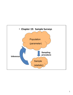
enhancement that this system can provide appears in Figure 1.
Figure I. Top display shows pulse train data captured by waveform recorder alone (20 MHz conversion
rate). Lower display shows same input captured using system described in this note.
Performance characteristics for the 5180A Sampling System are summarized in the table below:
5180A Input
Channel
Maximum Recommended
Input Frequency
(3 dB Bandwidth)
A or B
40 MHz
Auxiliary
70 MHz
Maximum Effective
Sample Rate
20 GHz
An indication of the quality of the data as a function of the input frequency (dynamic performance)
for the system is shown in Figure 9, which summarizes the results of extensive sine wave curvefit
testing.*
Highlights of System Operation
In addition to the 5180A Waveform Recorder, the 5180A Sampling System requires a programmable
timing generator and an instrument controller. The system implementation described in this note uses
a 5359A Time Synthesizer and a 9826 Controller. Figure 2 shows the set-up.
XYZ DISPLAY
9826
CONTROLLER
5359 TIME
SYNTHESIZER
s£
5180 WAVEFORM
Ext Trig I
I Output
(Any
Channel)
HP-GL
PLOTTER
(Optional)
POWER
SPLITTER
Input -
Figure 2. 5180A sampling system.
The measurement technique is similar to that used in a sampling scope - the sample point is walked
through the input by successively increasing the delay between the occurrence of an input trigger and the
time the input is sampled. As can be seen from Figure 2, the 5359A is externally triggered by the input
signal. * * The time between occurrence of this trigger and the output of a pulse from the 5359A is precisely
controllable (increments as small as 50 picoseconds), so the 5359A provides the variable delay capability.
The output pulse from the 5359A is the input that tells the 5180A when to sample the input signal. A
detailed description of the system operation appears in the next section.
*The sine wave curvefit test is an ADC (Analog-to-Digital Converter) performance measure used by Hewlett-Packard and other
waveform recorder producers to evaluate the overall quality of the analog-to-digital conversion process. This test is particularly
meaningful because it incorporates many of the error factors that can degrade ADC performance.
* *For repetitive inputs that don11 have a uniquely definable trigger within one period of the input waveform, such as phase coherent
pulsed RF (no unique trigger is definable because the signal passes through the same level with the same slope many times within
one period), another trigger signal must be generated. For example, with phase coherent pulsed RF, the modulating signal could be
used as the trigger.
Here's How it Works
When the 5180A Sampling system is collecting data it iterates through a simple procedure that
can be described in chronological steps:
STEP A:
The input passes through the exernal trigger level set on the 5359A Time Synthesizer,
thus triggering it.
STEP B:
The amount of delay time that has been programmed into the 5359A elapses.
STEP C:
At the end of the delay time the 5359A generates a pulse.
STEP D:
The output pulse, being the timebase for the 5180A, causes the 5180A to sample the
input once.
STEP E:
After the 5359A output pulse has occurred, the 5359A is automatically re-armed
and again becomes ready to accept an external trigger.
Steps A-E are repeated as many times as there are data points in the 5180A record (determined
by 5180A RECORD LENGTH value).
STEP F:
Once the record has filled, the data is output to the 9826 Controller and the 5359A
delay time is increased. Steps A-E are then repeated again.
The process continues until the desired number of measurements have been taken.
STEP G:
The measurement data is processed and the results are written to the 5180A, or may
be plotted on the 9826 display.
The 9826 Controller oversees the entire measurement process. This sequence of steps is depicted
in Figure 3. Figures 4 and 5 show the signal timing relationships.
Figure 3. Flow diagram for measurement process.
INPUT
WAVEFORM
S3S9A
Exwrnal
Trigger
L««l
(+ Slope)
5359A OUTPUT
Figure 4. Timing relationships for 5180A sampling system. To is 5359A delay time. • indicates the value of
the input when the sample occurs.
INPUT
SIGNAL
5359A
External
Ttiwer
Level
H Slope)
One Record Of Samplei
Taken Here
Figure 5. Successive data records are collected at successive time delays for complete sampling of input.
Processing the Data
As each data record is output to the 9826 Controller, the data may be averaged and the average
saved or a single data point can be saved. Averaging the data is useful for removing noise (random)
components from the input signal. The "smoothing" effect of averaging is illustrated in Figure 6.
Whether the data is averaged or not, the input signal is reconstructed by plotting or displaying the
saved data point from each record versus the value of the time delay associated with that record.
6A. No averaging.
6B. Each sample is average of 100 samples.
Figure 6. Averaging reduces the effect of random noise.
Putting the System Together
The equipment set-up and required interconnections are shown in Figure 2. A step-by-step
procedure for making the 5180A Sampling System operational is provided below:
1. Complete the system interconnections according to Figure 2. HP-IB device addresses are: 04 for
the 5180A, and 10 for the 5359A.
2. A rotary switch near the 5180A's timebase-in input can be set to sample at various input levels:
-1, -.3, 0, or 1.8 volts into 50 ohms. Since the 5359A has flexible output level capability, any of
the 5180A's timebase-in threshold levels could be used. The simplest choice is to set the rotary
switch for a zero volt threshold (position 3).
3. Preset the 5180A by pressing the SHIFT key followed by the key marked PRESET. Position
the rear-panel INT/EXT timebase switch to EXT, and select the AUTO sweep arming mode.
4. Set the 5359A front panel to:
Sync Delay
Preset
Polarity
Norm and Pos
Offset
On
5. On power-up the 5359A outputs a 1 MHz repetitive pulse train. This signal is convenient for
establishing that the 5359A output is actually causing the 5180A to sample. Set the output level on
the 5359A by pressing DISPLAY LEVELS to bring up the amplitude and offset values on the
5359A display. Adjust the amplitude to about 2 volts with a -1 volt offset. This should cause the
output pulse to change from -1 to 1 volt, thus assurring that the 5180A timebase-in threshold
level is crossed. If sampling is occurring the input signal will be changing on the XYZ display and
the ARM and TRIG annunciators on the 5180A will be flashing. If the 5180A isn't sampling, check
and adjust the 5359A output levels.
6. Having verified that the 5359A output is causing the 5180A to sample, the final hardware step
is to set the external trigger level on the 5359A. With input signal applied press the DELAY key
on the 5359A. The 5359A display will blank, indicating that it's waiting for you to input a delay
value. Press 10 (data entry section) followed by ns (units section). This entry specifies that the
5359A will output a pulse 10 nanoseconds after the occurrence of an external trigger (there is
some additional fixed delay, but this isn't important). Use the external trigger level adjustment
to set an appropriate external trigger level. To verify that an unambiguous trigger level has been
chosen, view the captured waveform on the XYZ display. The waveform should be live and
essentially a horizontal line. The display represents the data for one sample point of the repetitive
input. Since all the data is being taken at the same delay time after the 5359A is externally
triggered, you would expect the displayed waveform to be a horizontal line (see Figure 4). If it isn't
horizontal, or if the 5180A isn't sampling, adjust the external trigger level on the 5359A.
Once the previous six steps have been successfully completed the system hardware is operational.
The system software remains to be loaded into the 9826 Controller. The system software, with
documentation and a variable list, is presented in the appendix.
Some of the key features of the 5180A Sampling System software are:
•
Softkeys are used to control all system functions.
•
Using the softkeys the following parameters can be controlled by the user:
1)
2)
3)
4)
5)
Effective sample rate
Number of samples per measurement
Extent of averaging per sample point
5180A record location for storing measurement results
High-speed or Normal acquisition mode. The normal acquisition mode uses the measurement procedure of Figure 3. The high-speed mode employs a slightly different procedure,
using the 5180A's AUTO ADVANCE feature to sample up to 32 points before any data is
output from the 5180A.
Once the data is collected and processed in the 9826 it is automatically written back into the
5180A. The 5180A display controls can then be used to examine the captured waveform. The
amplitude levels are accurate but no time per sample information is available from this display.
The PLOT softkey displays the measurement result on the 9826 display. An advantage of this
display over the data as stored and displayed by the 5180A is that the scaling is optimized on
the 9826 display for the actual amplitude and time range of the measurement. A dot/line mode
similar to this feature on the 5180A is provided on the 9826 display. Also, a cursor may be enabled
for simultaneous time and voltage readout of the data on the 9826 display. These readouts appear
in the softkey menu area. Positioning of the cursor is controlled via the 9826 control knob.
Illustrations of the 9826 display plot appear below.
+ . £3
t.55
\
•-. 39
i±
I-
+.3L
O
-.13
-.£6
-.40
\
A
A
M
,•
/ \
\ / \ M /
\
\
\
\
\\ i \
\1 \
\
-l.E-B
B.E-B
J.2C-7
1 5E-7
2E-r
TIME ' SEC'IfJDS .'
EXIT
TIME
VOLTAGE
PLOT
1.36E-7
.49
7A. 9826 plot using LINE mode.
+ . ba
+ .55
•
+ .41
+ . 38
.
•
CE
I—
+.QI
0
-.13
-.40
.
.
4.E-B
9 . E-B
TIME
1 .2E-7
I 6E-7
2 . E-7
' SEC Of. JDS )
EXIT
TIME
PLOT
1.48E-7
VOLTAGE
.406
7B. 9826 plot using DOT mode.
8
Figure 7. The cursor voltage and time values appear in the softkey menu.
XYZ DISPLAY
PLOT GENERATED BY 9826 CONTROLLER
8A. Square wave output captured using sampling technique. Effective sample rate is 667 MHz. (1.5
nanoseconds/sample).
uw«; :--«:«
i
hp
5180A WAVEFORM RECORDER
Me.
XYZ DISPLAY
to.
Bl»t.
5180A GENERATED PLOT
SB. 53.64 MHz sine wave captured using sampling technique. Effective sample rate is 4 GHz. (250
picoseconds/sample).
hp
XYZ DISPLAY
5180A WAVEFORM RECORDER
5180A GENERATED PLOT
8C. Output captured using sampling technique. Effective sample rate is 1 GHz. (1 nanosecond/sample).
Figure 8. Examples of system output.
Measurement Considerations
An indication of typical dynamic performance for the 5180A Sampling System is shown in Figure 9,
which plots input frequency versus effective bits (an excellent description of "effective bits" and the
test that determines this result appears in 5180A Product Note 5180-2).
Effective Bit Performance of
5180A Sampting System
100 Averages
— • — • 10 Averages
Single Shot
3
4
5
6
7 8 9 10
20
30
40
50 60 70 80 100
Input Frequency (MHz)
Figure 9. Dynamic Performance data for 5180A Sampling System. Effective sample rate was 500 MHz.
Other important considerations regarding the performance of the 5180A Sampling System are
described below.
1. 5180A INPUT BANDWIDTH
The input bandwidths of the 5180A (see table, page 2) impose an upper limit on the frequency
extension range of the system. Since the 5180A front-end can be modeled as a single-pole low pass
filter (for any of the input channels), data can be collected beyond the 3 dB point, but attenuation and
phase-shifting will affect the data according to Figures 10 and 11.
2. 5359A EXTERNAL TRIGGER BANDWIDTH
Since the 5359A Time Synthesizer is externally triggered by the input signal in most implementations of
the system (for an exception see the footnote on page 4}, the external trigger bandwidth can impose
limitations. Measurements taken to evaluate this limitation indicate that the 5359A will trigger reliably for
inputs up to 100 MHz.
3.
5359A MINIMUM DELAY STEP SIZE
The 5359A delay step is the effective time per sample of the 5180A Sampling System. Since the
minimum delay step size on the 5359A is 50 picoseconds, the maximum effective sample rate is
1/50 picoseconds = 20 GHz. NOTE: This doesn't mean, of course, that inputs in the GHz range can be
captured using the 5180A Sampling System (see the previous two points for the reasons). It does mean
that lower frequency, repetitive inputs can be sampled at a 20 GHz rate.
10
-20
"OUT
dB -30
40
10
40
50
60
70 80 90 100
200
300
400
500
Input Frequency (MHz)
Figure 10. AOUT: Output magnitude (value measured in 5180A)
A1N: Input magnitude
Auxilary Channel
— A or B Channel
Phase Error
vs.
Input Frequency
for 5180A
Input Channels
10
100
Input Frequency (MHz)
Figure 11.
11
4. 5359A OUTPUT STABILITY
Since the 5359A controls the sampling of the 5180A Waveform Recorder, the output jitter of the
5359A is actually the aperture uncertainty of the 5180A Sampling System. The effect of aperture
uncertainty is a factor in the effective bit measurement. 5359A output jitter (specified at 100 picoseconds TYPICAL) is probably the main cause of performance degradation with increasing
input frequency.
5. SYSTEM ACQUISITION TIME
Since the measurement technique requires multiple passes through the input signal before the data
can be processed, the time to acquire the signal is an important measurement consideration. The
acquisition time is the time between collecting the first data point in the first data record and the
last data point in the last record. Acquisition times for the 5180A Sampling System are shown in
Figure 12.
ACQUISITION TIMES FOR
FREQUENCY EXTENSION SYSTEM
~ Single shot
10 Averages
10OAverages
1000 Averages
Number
of
Sample
Points
20
10
15
Time (Seconds)
"Amount of averaging has no effect on acquisition time
12
Figure 12.
20
Appendix : 5180A Sampling System Software
The 5180A Sampling System is controlled by the system software listed in this appendix. The
program is written for BASIC as implemented in the 9826A controller. The structure of the software
should be evident from the variable list and documentation included alongside the program listing.
To operate the system software is simple: after pressing RUN all of the user options appear in the
softkey menu. To modify a parameter, press the appropriate softkey, respond to the prompt, and
press CONTINUE on the 9826.
The DISPLAY, PLOT, and CURSOR subroutines are useful as general purpose subroutines and
could be used with the 5180A in any application to bring the data up on the 9826 display. Although
not implemented in this listing, it should be possible to modify the HISPEED subroutine to sample
more than 32 points. This could be accomplished using a DMA data transfer from the 5180A to the
9826 following each filling of the 5180A memory. The transferred data could be held in the controller
while another series of 32 measurements is taken. This process could be repeated many times (the
9826 has plenty of memory to hold the unprocessed data) and then finally, all the data in the 9826
could be processed to obtain the measurement result.
Variable List and Definitions : in Order of Appearance in the Program
C$[*]
: used to store 5180A teach strings
Code(*)
: Data array (if memory limitations become important, Code(*) could be
ALLOCATED (see 9826 manual) a size of the variable "Length", instead of
being dimensioned).
Location
5180A record location where processed data will be stored
Average
Number of averages per sample point
R
Effective sample rate
Samples
Number of samples per measurement
Length
5180A record length
Flag
Indicates high-speed or normal measurement mode
C
Temporary data storage
Stay
Flag to allow new display plot on 9826
Channel
5180A input channel (1=A, 2=B, 4=auxiliary)
Range
5180A input range
Offset
5180A offset
Minimum
Minimum Code(*)
Maximum
Maximum Code(*)
Vmax
Maximum voltage of data
Vmin
Minimum voltage of data
Connect
Flag identifying dot or line mode for 9826 display plot
Mov
Variable indicating cursor position for 9826 display plot
Old
Previous value of Mov
Left
Indicates Sample range over which data must be re-plotted on 9826 display
following a cursor erase
13
i
10
20
I5180A S A M P L I N G SYSTEM
!
30
!
40 •lain:
50
DIM ,C$[ 300] , Code (16 38 4)
60
A$="MORMAL"
70
Length-512
30
Location=l
90
Average=l
G R A P H I C S OFF
100
ASSIGN @Hp5l80 TO 70 41
110
ASSIGN @Hp5359 TO 710J
120
130
Orf KS£ 0 LABEL "TIME/PT" GOSU3 Sample
140
01S KEY 2 LABEL "SAMP = " & V A L $ ( Samples) GOSUB N u m b e r
OLN! K3¥ 3 LABEL A$ GOSU3 Mode
150
ON KEY 4 LABEL " M E A S U R E " GOSUB M e a s u r
160
170
ON KEY 5 LABEL V A L $ ( R ) GOSUB Sample
180
ON KE* 7 LABEL " R E C = " & V A L $ ( L o c a t i o n ) GOSU3 Racori
ON K E Y 8 LABEL "Av r E = "&\/AL$( W e r a g e ) G 03 J3 A v e r a g e
190
Otf KEY 9 LABEL "PLOT " GOTO 1110
200
D I 3 P "SELECT D E S I R E D F U N C T I O N "
210
OFF KM 03
220
30TO 130
230
i
240
!
250 S a m p l e :
260
I N P U T " E t f T E R SAMPLE RATE" ,R~
270
O J T P U T @ U p 5 3 5 9 ; " D3S"
230
RQTURN
i
290
!
300 d u m b e r :
310
I N P U T " E N T E R N U M B E R 3 ? S A -'-IP LES" r 3 a mp le si
320
RETURN
i
330
340 A v e r a g e : 1
350
I N P U T " C N T E R A V E R A G E S P E R SAMPLE" ,Ave rage
F O R 1=9 T O 14
360
I F A v e r a g e < 2 " l f H E N 3DTO 3 9 )
370
380
NEXT I
Length=2~I
390
R£ T U R N
_
400
i
410
i
420 Mode:
I F Flag=0 T d E . 4
430
<\$ = ";il- SPEED"
440
Flag=l
450
ELSE
460
\ $ = " N O R MAL"
470
480
Flag=0
s ;-4 o IF
490
.
RETURN
500
i
510
520 M e a s u r e : !
O I S P " M E A S U R E M E N T 1^ P R O G R E S S "
530
O U T P U T :3ilp5359; " D O G - y , ft 2 u h ^
540
550
O U T P U T (33^5180; "TE1, 3 A 3 , S E l r i ? P 5 , L 3 ," , C U M U L I 560
FOR 1=1 ro Samples
570
C o d e ( I ) =0
530
NEXT I
Initialize
A«~
^^ name
Assign
l/U rath
for 5180A and 5359A
fin n
H r f i n c oon
^ift ^eys
Ifmueiue
Prnnram
Fffpftii/p
r i u y i a i n tricnivc
Sample Rate
^ — -.
^.
of samples
UCVCI I N N 1C I I U I I IUCI
ueier
n_t
;
„ ^
t nt
averaging and
compute appropriate
5180A record length
Hi-speed or
n r n i l l lUlnnn. .
- n»
~~ M
IMUlllldl
IvlcdaUlclIlcill
rnn
n
Mode
"ct up 5359A
Scl-Up DloUft
590
IF Flag=l T H E N GOTO Hispeed
600
OUTPUT @ H p 5 1 8 0 ; " L O , " , L o c a t i o n
610
FOR 1=1 TO Samples
620
630
640
650
OUTPUT @tfp5180;"MT"
IF B I T ( S P O L L { 7 0 4 ) , 3 ) = 0 T H E N GOTO 630OUTPUT @Hp5180? " O S P " , Location"
OUTPUT @ H p 5 1 8 0 ; 0 , A v e r a g e
660
- set-up 5180A for selective
ASCII output
FOR J=l TO Average
670
680
690
700
710
ENTER @Hp5130;C
Code(I)=Code(I)+C
NEXT J
Code(I)=Code(I}/Average
OUTPUT @ H p 5 3 5 9 ; " D S U "
720
NfiXT
730
GOSUB Display
740
750
LOCAL @Hp5180
RSTURN
760
!
Averaging
Loop
Main
Measurement
Loop
increase the delay time
I
770 d i s p e e d :
!
780
OUTPUT <afrlp5180; "ADO,L01,\A1" ~|_
790
OUTPUT (3Hp5130; "SA3"
_T
800
Samples = (16384/1 N T ( L e n g t h ) )
310
320
330
340
850
360
370
380
890
900
DI3P " M E A S U R E M E N T IN PROGRESS"
FOR 1=1 fO Samples
0U TPUT &Ip513 0; " MT "
IF 3 I T ( S P O L L ( 7 0 4 ) ,3) =0 TH2N
OUTPUT iatip5359?"DSU"
NEXT I
FOR 1=1 TO Samoles
DI3P "ACQUISITION COMPLETE"
OUTPUT PHp513Q;"OS, ",i
OUTPUT @dp5130;0,Average
910
FOR J=I TO A v e r a g e
920
930
940
950
960
970
ENTER @Hp5180;C
Code(I)=Code(I)+C
NEXT J
Code(I)=Code(I)/Average
NEXT I
G3TO 730
980
1
set-up 5180, use
• Auto-Advance mode
-determine number of available 5180A records
;OTO 840
990 D i s p l a y : !
1000
F J R I = S a m p l e s + l TO L e n g t h
1010
IF 3 a m p l e s = L e n g t h THEN GOTO 1040
1020
Code(I)=512
1030
NEXT I
1040
OUTPUT £Hp5180;"JB,",Location
1050
FOR 1=1 TO L e n g t h
1060
OUTPUT taao5180;Code(I)
1070
NEXT I
1080 O U T P U T O H p 5 1 3 0 ; " T L , " r L o c a t i o n
1090 R3TURN
1100
- Trigger 5180A
- wait for 5180A record to fill
High Speed
•Measurement Loop
• Data Processing Loop
Fill all extra points in
• 5180A record with a baseline
- set-up 5180A to accept processed data
write data into 5180
!
1110 Plot: !
1120
3tay=0
1130
O I 3 P ""
1140
JFF K^Y
115J 0,^F K N O B
1160 ON K?* 0 L A 3 E L " C X I T " GOTO 100
1170
ON rCS* 2 L A 3 E L "CURSOR" JOTO 1890
Redefine Soft Keys
1130
1190
1200
1210
1220
1230
1240
1250
1260
1270
1280
1290
1300
1310
1320
1330
1340
1350
1360
1370
1380
1390
1400
1410
1420
1430
1440
1450
1460
1470
1430
1490
1500
1510
1520
1530
1540
1550
1560
1570
1590
1600
1610
1620
1630
1640
1650
1660
1670
1630
1690
1700
1710
1720
1730
174u
ON
ON
ON
IF
KSY 4 LABEL
KfiiT 5 LABEL
KSY 9 LABEL
3tay=l THEN
"DOT" GOTO 1810
"PLOT" GOTO 100
" L I N E " GOTO 1850J
30TO 1210
• Redefine Soft Keys
3CLSAR
3RAPHICS ON
VIEWPORT 20,125,20,90
W I N D O W 0 ,100,0,100
CLIP ON
AXSS
20,10,0,0
CLIP OFF
C3IZE 5
.40 VE 50 ,-15
LABEL " T I M E (SECONDS) 1 1
DE3
L O I R 90
-10VE -17,50
LABEL "VOLTAGE"
ODIR 0
23IZE 3.4
LOR3 5
OUTPUT @ap5180;"01,",Location
E N T E R <3Hp5180;C$
FOR 1=1 TO L E N ( C $ )
IF C $ [ I , I ] = " " T H E N C $ [ 1 , 1 ] = " + "
NEXT I
C n a n n e l = V A L ( C $ [ P O S ( C $ , " c ^ " ) 2| 0
IF Channel=l THEN 3$="a"
IF Channel=2 THEN B $ = " o "
R a n g e = V A L ( C $ [ i ? 0 3 ( C $ , B $ & " r " ) -2| )
Of f s e t = V A L . ( C $ [ P O S ( C S , 3 $ & " o " + 2|.)
IF C h a n n e l = 4 THE.^ Range = l
IF ChannelM THEN Offset=0
Minimum=1023
FOR 1=1 TO Samples
I F Code ( I ) X l a x i m u m THEN '4aximum=Code ( I )
IF Code (I) <MininiUTi THEN .4ininum=Code ( I )
NEXT I
V m a x = R a n g e * ( ^axiTiam- :>
v.nin- - U K J O * ( Minimum -51 2) *. 002-Of f s e t ,
W I N D O W 0 , R * 3 a m p l e s , Vmin, Vniax
get axes and
title on
9826 display
- output and read input amplifier
teach string from 5180A
Determine 5180A
input channel,
range, and offset
Find data
minimum and
maximum
convert 5180A offset binary code
to true voltage value
FOR 1=1 PO 10
M O V E -. l*R*3amples , V^nin+( (V,Tiax-Vmin) *I/10)
LABEL U S I N G " SDD .00" ; V m i n+( ( VTiax-Vm in) *I /10)
NEXT I
FOR I =1 TO 5
.-10VE R * S a m p l e s * I / 5 , V m i n - . 07* ( V m a x - V m i n )
LA3EL R*3amples*I/5
NEXT I
FOR I =1 TO Samples
IF Connact = i AND I>1 THEN GOTO 1710
I*R,Range*(Code(I)-512)*.002-Offset
DRAW I * R , R a n g e * ( C o d e ( I ) - 5 1 2 ) * . 0 0 2 - O f f s e t
NExr I
GOTO 1130
label voltage
axis values
label time
• axis values
plot the data
1750
1760
1770
1780
1790
1800
1810
1320
1830
1840
1850
1860
1870
1830
1890
1->00
1910
1920
1930
1940
1950
1960
1970
1930
1990
2000
2010
2020
2030
2040
2050
2050
2070
2030
2090
2100
2110
2120
2130
2140
2150
2160
2170
2180
2190
2200
2210
2220
2230
2240
2250
i
Record: !
I N P U T " E N T E R RECORD LOCATION" , Location
RETURN
i
Dot:
!
C o n n e c t = 0 ~|
GOTO 1220J
I
C o n n e c t : 1~
^ onnect— 1
GOTO 1220_
i
Cursor:
i
1
flov=I NT ( Samples /2)
01d=Mov
CLIP OFF
CSIZE 6
iOTO 2040
ON KN03 .04,15 JOTO 19601
GOTO 1950
OFF KN03
;4ov=(KNOBX+Mov)
I F Mov>Samoles THEN Mov=Samples
_r
IF
01d=Mov T H E N GOTO
Determine 5180A record
location for data storage
Don't connect ths dat9 points
Lonnect trie oata points
Initialize
Cursor
Parameters
0
wilt fnr
1fl fi Lrnntrnl
— Wall
IUI 3OiO
iUllllUI
knob to turn
oetermine new
cursor position
1940
v— j o
c ^/ Joi
- L /^
u J\
.10VE 0 1 d * R , R a n g e * K ,Ou
L A B E L "*"
R II Z
O J\ ^* . UnUn o
D
Z "w 't t s e t
erase old cursor
PEN 1
L e f t = I N T ( S a m o l e s / 5 2 . 5)
IF Left=0 THEN Left=l
FOR I =-Lef t TO L e f t
IF Old+I <1 THEN GOTO 2130
IF Old+I >Samples THEN GOTO 2130
IF Connect = l A N D ( I > - L e f t AND O l d + l O l ) T H E N GOTO 2120 - Re-plot data
:40VE ( I - f 0 1 d ) * R , R - m g e * ( C o d e ( I + 0 1 d ) - 5 1 2 ) * . 002-Of f s e t
Krsor
DRAW ( l + O l d ) * R , R a n g e * ( C o d e ( I + 0 1 d ) -512) * . 0 0 2 - O f f s e t
erase
NEXT I
'40 VE 01d*R, R a n g e * (Code ( O l d ) -512) *. 002-Of f s e t
DRAW 01d*R, R a n g e * (Code ( O l d ) -512)*. 002-Of f s e t
>10VE Mov*R, R a n g e * (Code (Mov)-512) *. 002-Of f s e t
ON K S ¥ 2 L A J E L " T I M E " GOTO 2170
Put cursor information
ON KEY 3 LABEL "VOLTAGE" GOTO 2180
in Soft Key label area
ON KEY 7 LABEL V A L $ ( M o v * R ) G03U8 R e t u r r i1
ON KEif M o LABEL V A L $ ( Range* ( Code ( M o v ) -5].2) *. 0 0 2 - O f f s e t ) 303 JB R e t u r n
r A T"Ic5 r?EjLi
r
Ltr\
* '
Old- Mov
GOTO 1940
Return:
RETURN
END
draw the cursor
save cursor position
HEWLETT
PACKARD
For more information, call your local HP Sales Office or nearest Regional Office: Eastern (201) 265-5000; Midwestern (312) 255-9800; Southern (404) 955-1500; Western (213)
970-7500; Canadian (416) 678-9430. Ask the operator for instrument sales. Or write Hewlett-Packard. 1501 Page Mill Road, Palo Alto, CA 94304. In Europe: Hewlett-Packard
S.A., 7, rue du Bois-du-Lan, P.O. Box, CH 1217 Meyrin 2, Geneva, Switzerland. In Japan: Yokogawa-Hewlett-Packard Ltd., 29-21, Takaido-Higashi 3-chome, Suginami-ku, Tokyo 168.
02-5952-7637
PRINTED IN U.S.A.


© Copyright 2026