
PHYSICS CLASS - XII SAMPLE PAPER BLUE PRINT
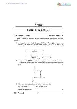
PHYSICS
CLASS - XII
SAMPLE PAPER
BLUE PRINT
S. No.
Unit
(1 mark)
SA I
(2 marks)
SA II/VBQ*
(3 marks)
VSA
LA
TOTAL
(5 marks)
1.
Electrostatics
1 (1)
4 (2)
3 (1)
8 (4)
2.
Current
Electricity
2 (2)
2 (1)
3 (1)
7 (4)
3.
Magnetic effect
of current &
Magnetism
4(2)
3 (1)
8 (4)
4.
Electromagnetic
Induction and
Alternating
Current
5.
Electromagnetic
Waves
6.
Optics
7.
Dual nature of
Radiation and
matter
8.
Atoms and
Nuclei
9.
Electronic
Devices
10.
Communication
Systems
2 (2)
Total
8 (8)
1 (1)
2 (1)
5 (1)
8 (3)
3 (1)
1 (1)
2 (1)
6 (2)
5 (1)
4 (2)
4 (2)
3 (1)
3 (1)*
2 (1)
6 (2)
5 (1)
3 (1)
20 (10)
14 (5)
27 (9)
7 (2)
5 (3)
15 (3)
70 (30)
The question paper will include value based question(s) to the extent of 3–5 marks.
13
PHYSICS CLASS-XII
SAMPLE PAPER-1
Q1.
A magnet is being moved towards a coil with a uniform speed as shown in the
figure. State the direction of the induced current in the resistor R.
1
Q2.
A square coil, OPQR, of side a, carrying a current I, is placed in the Y-Z plane as
shown here. Find the magnetic moment associated with this coil.
1
Q3.
Give one example each of a ‘system’ that uses the
(i)
Sky wave
(ii)
Space wave
mode of propagation
1
Q4.
A concave mirror, of aperture 4cm, has a point object placed on its principal axis
at a distance of 10cm from the mirror. The image, formed by the mirror, is not
likely to be a sharp image. State the likely reason for the same.
1
Q5.
Two dipoles, made from charges q and Q, respectively, have equal dipole
moments. Give the (i) ratio between the ‘separations’ of the these two pairs of
charges (ii) angle between the dipole axis of these two dipoles.
1
14
Q6.
The graph, shown here, represents the V-I characteristics of a device. Identify the
region, if any, over which this device has a negative resistance.
1
Q7.
Define the term ‘Transducer’ for a communication system.
Q8.
State the steady value of the reading of the ammeter in the circuit shown below.
1
1
Q9. The following table gives data about the single slit diffraction experiment:
Wave length of Light
Half Angular width of
the principal maxima
p
q
Find the ratio of the widths of the slits used in the two cases. Would the ratio of
the half angular widths of the first secondary maxima, in the two cases, be also
equal to q?
2
Q10. N spherical droplets, each of radius r, have been charged to have a potential V
each. If all these droplets were to coalesce to form a single large drop, what
would be the potential of this large drop?
(It is given that the capacitance of a sphere of radius r equals 4
15
kr.)
OR
Two point charges, q1 and q2, are located at points (a, o, o) and (o, b, o)
respectively. Find the electric field, due to both these charges, at the point,
(o, o, c).
2
Q11. When a given photosensitive material is irradiated with light of frequency , the
maximum speed of the emitted photoelectrons equals max. The square of max,
i.e., max2, is observed to vary with , as per the graph shown here.
Obtain expressions for
(i)
Planck’s constant, and
(ii)
The work function of the given photosensitive material,
in terms of the parameters
n and the mass, m, of the electron.
Q12. For the circuit shown here, would the balancing length increase,
decrease or remain the same, if
(i)
(ii)
2
R1 is decreased
R2 is increased
without any other change, (in each case) in the rest of the circuit. Justify your
answers in each case.
16
Q13.
Find the P.E. associated with a charge ‘q’ if it were present at the point P with
respect to the ‘set-up’ of two charged spheres, arranged as shown. Here O is the
mid-point of the line O1 O2.
2
Q14.
An athlete peddles a stationary tricycle whose pedals are attached to a coil
having 100 turns each of area 0.1m2. The coil, lying in the X-Y plane, is rotated,
in this plane, at the rate of 50 rpm, about the Y-axis, in a region where a
uniform magnetic field,
(i) maximum emf
= (0.01)
tesla, is present. Find the
(ii) average e.m.f
generated in the coil over one complete revolution.
2
Q15.
A monochromatic source, emitting light of wave length, 600 nm, has a power
output of 66W. Calculate the number of photons emitted by this source in
2 minutes.
2
Q16.
For the circuit shown here, find the
current flowing through the 1 resistor.
Assume
that the two diodes, D1 and D2, are ideal
diodes.
Q17.
The following table shows the range of values of susceptibility and relative
magnetic permeability of two different type of magnetic substances
2
Substance
Susceptibility
Magnetic Permeability
X
-1 to 0
0 to 1
Y
>> 1
>> 1
17
(a)
Identify the type of magnetic materials X and Y.
(b)
How does the susceptibility and permeability of X and Y vary with rise in
temperature?
2
Q18.
Two wires are aligned parallel to each other. One is carrying an electric current
and the other is not. Will there be any kind of electromagnetic force between
the two? Give reason for your answer.
2
Q19.
The galvanometer, in each of the two given circuits, does not show any
deflection. Find the ratio of the resistors R1 and R2, used in these two
circuits.
3
Q20.
The electron, in a hydrogen atom, initially in a state of quantum number n1
makes a transition to a state whose excitation energy, with respect to the
ground state, is 10.2 eV. If the wavelength, associated with the photon emitted
in this transition, is 487.5 mm, find the
(i)
energy in ev, and (ii) value of the quantum number, n1 of the electron in
its initial state.
3
OR
The spectrum of a star in the visible and the ultraviolet region was observed
and the wavelength of some of the lines that could be identified were found to
be
824 Å, 970 Å, 1120 Å, 2504 Å, 5173 Å, 6100 Å.
Which of these lines cannot belong to hydrogen atom spectrum? Support your
answer with suitable calculations.
Take Rydberg constant R = 1.03 X 10⁷ m-1 and = 970 Å.
18
Q21.
Three identical polaroid sheets P1, P2, and P3 are oriented so that the (pass) axis
of P2 and P3 are inclined at angles of 600
and 900, respectively, with respect to
the (pass) axis of P1. A monochromatic
source, S, of intensity I0, is kept in front
of the polaroid sheet P1. Find the
intensity of this light, as observed by
observers O1, O2, and O3, positioned as
shown below.
Q22.
A fine pencil of -particles, moving with a speed , enters a region (region I),
where a uniform electric and a uniform magnetic field are both present. These
-particles then move into region II where only the magnetic field, (out of the
two fields present in region I), exists. The path of the -particles, in the two
regions, is as shown in the figure.
(i)
State the direction of the magnetic field.
(ii)
State the relation between ‘E’ and ‘B’ in region I.
(iii)
Drive the expression for the radius of the circular path of the -particle in
region II.
If the magnitude of magnetic
field, in region II, is changed
to n times its earlier value,
(without
changing
the
magnetic field in region I)
find the factor by which the radius of this circular path would change. 3
Q23.
Draw an appropriate ray diagram to show the passage of a ‘white ray’, incident
on one of the two refracting faces of a prism. State the relation for the angle of
deviation, for a prism of small refracting angle.
It is known that the refractive index, , of the material of a prism, depends on
the wavelength , , of the incident radiation as per the relation
=A+
19
where A and B are constants. Plot a graph showing the dependence of on
and identify the pair of variables, that can be used here, to get a straight line
graph.
3
Q24.
Excessively large amount of energy is released in an uncontrolled way in a
nuclear bomb explosion. Some scientists have expressed fear that a future
nuclear war on Earth would be followed by a severe ‘nuclear winter’ with a
devasting effect on life on Earth.
3
Answer the following questions based on above possible scenario:
Q25.
a)
Name the basic principle responsible for release of large amount of energy
in a nuclear bomb explosion. How will the nuclear bomb explosion result
in ‘nuclear winter’?
b)
Which two human values need to be promoted in individuals so that such
a situation of nuclear winter does not arise?
c)
Suggest any one method to promote these values in school students.
The modulation index of an amplitude modulated wave is 0.5. What does it
mean?
Calculate the modulation index for an AM wave for which the maximum
amplitude is ‘a’ while the minimum amplitude is ‘b’.
3
Q26.
The capacitors C1, and C2, having plates of area A each, are connected in series,
as shown. Campare the capacitance of this combination with the capacitor C 3,
again having plates of area A each, but ‘made up’ as shown in the figure.
3
3
Q27.
(a)
Write the formula for the velocity of light in a material medium of relative
permittivity r and relative magnetic permeability r.
1
20
(b)
The following table gives the wavelength range of some constituents of
the electromagnetic spectrum.
S.No.
Wavelength Range
1.
1mm to 700nm
2.
0.1m to 1mm
3.
400 nm to 1nm
4.
< 10 3 nm
Select the wavelength range, and name the (associated) electromagnetic waves,
that are used in
(i) Radar systems for Aircraft navigation
(ii) Earth satellites to observe growth of crops.
Q28.
2
A conducting rod XY slides freely on two parallel rails, A and B, with a
uniform velocity ‘V’. A galvanometer ‘G’
is connected, as shown in the figure and
the closed circuit has a total resistance ‘R’.
A uniform magnetic field, perpendicular
to the plane defined by the rails A and B
and the rod XY (which are mutually
perpendicular), is present over the region,
as shown.
(a)
With key k open:
(i)
Find the nature of charges developed at the ends of the rod XY.
(ii)
Why do the electrons, in the rod XY, (finally) experience no net force
even through the magnetic force is acting on them due to the motion
of the rod?
(b)
How much power needs to be delivered, (by an external agency), to keep
the rod moving at its uniform speed when key k is (i) closed (ii) open?
(c)
With key k closed, how much power gets dissipated as heat in the circuit?
State the source of this power.
21
OR
‘Box’ A, in the set up shown below, represents an electric device often
used/needed to supply, electric power from the (ac) mains, to a load.
It is known that Vo < Vi.
Q29.
(a)
Identify the device A and draw its symbol.
(b)
Draw a schematic diagram of this electric device. Explain its principle and
working. Obtain an expression for the ratio between its output and input
voltages.
(c)
Find the relation between the input and output currents of this device
assuming it to be ideal.
5
Define the terms ‘depletion layer’ and ‘barrier potential’ for a P-N junction
diode. How does an increase in the doping concentration affect the width of the
depletion region?
Draw the circuit of a full wave rectifier. Explain its working.
OR
Why is the base region of a transistor kept thin and lightly doped?
Draw the circuit diagram of the ‘set-up’ used to study the characteristics of a
npn transistor in its common emitter configuration. Sketch the typical (i) Input
characteristics and (ii) Output characteristics for this transistor configuration.
How can the out put characteristics be used to calculate the ‘current gain’ of the
transistor?
Q30.
(i)
A thin lens, having two surfaces of radii of curvature r1 and r2, made
from a material of refractive index , is kept in a medium of refractive
index . Derive the Lens Maker’s formula for this ‘set-up’
22
(ii)
A convex lens is placed over a plane mirror. A pin is now positioned so
that there is no parallax between the pin and its image formed by this
lens-mirror combination. How can this observation be used to find the
focal length of the convex lens? Give appropriate reasons in support of
your answer.
OR
The figure, drawn here, shows a modified Young’s double slit experimental set
up. If SS2 SS1, = /4,
(i)
state the condition for constructive and destructive interference
(ii)
obtain an expression for the fringe width.
(iii) locate the position of the central fringe.
23
5
MARKING SCHEME
Q.No.
Value point/ expected points
Marks
Total
1.
From X to Y
1
1
2.
The magnetic moment, associated with the
coil, is
1
1
m
3.
(i)
= Ia2
Short wave broadcast services
½
(ii) Television broadcast (or microwave
links or Satellite communication)
½
1
4.
The incident rays are not likely to be
paraxial.
1
1
5.
As qa = Qa’, we have
½
=
and
1
½
= 0o
6.
Region BC
1
1
7.
A ‘transducer’ is any device that converts
one form of energy into another
1
1
8.
Zero
1
1
9.
Let d and d’ be the width of the slits in the
two cases.
½+½
and q =
½
=
½
Yes, this ratio would also equal q
10.
Total (initial) charge on all the droplets
24
2
= N x (4
0k
Also N x
½
r V)
r3 =
R=
R3
½
r
2
If V’ is the potential of the large drop, we
have
4
R x V’ = N x 4
V’ =
V=
½
kr x V
½
V
OR
We have
net
=
1
where
11.
and
2
net
=
1=
=
1+
2
½
+
2
2
-a + c
½
= -b + c
1
According
to
Kmax = m
max
Einestein’s
=
Equation:
–
½
This is the equation of a straight line having
a slope 2h/m and an intercept (on the max
axis) of
Comparing these, with the
given graph, we get
= or h =
12.
(i)
½
and
½+½
=
or
=
decreases
(The
potential
increase)
gradient
would
25
½+½
2
(ii) increases
(The terminal p.d across the cell would
increase)
13.
½+½
r1 = O,P =
½
r2 = O2 P =
½
½
V=
2
P.E of charge , q, at P = qV
=
14.
½
(i)
The maximum emf ‘ ’ generated in the
coil is,
½
=NBA
=NBA2 f
= [100 x 0.01 x 0.1 x 2
=
V
2
]V
1
0.52 V
(ii) The average emf generated in the coil
over one complete revolution = 0
15.
½
Energy of one photon = E =
½
E=
½
3.3 x 10⁻¹⁹ J
2
E1 = energy emitted by the source in one
second = 66J
number of photons emitted by the source
in 1s = n =
= 2 x 10²⁰
½
Total number of photons emitted by
26
source in 2 minutes
= N = n x 2 x 60
16.
= 2 x 1020 x 120 = 2.4 x 10²² photons
½
Diode D1 is forward biased while Diode D2
is reverse biased
½
Hence the resistances, of (ideal) diodes, D1
and D2, can be taken as zero and infinity,
respectively.
½
The given circuit can, therefore, be redrawn
as shown in the figure.
2
½
Using ohm’s law,
I=
½
A = 2A
current flowing in the 1 resistor, is 2A.
17.
(a)
X-Diamagnetic,
Y-Ferromagnetic
(b) X- No change
(c) Y- Decreases with temperature
18.
No
-
19.
Since there is only one magnetic field,
there is no interaction and hence no
force between the two wires.
For circuit 1, we have, (from the Wheatstone
bridge balance condition),
27
½
½
R1 = 6
In circuit 2, the interchange of the positions
of the battery and the galvanometer, does
not change the (wheatstone Bridge) balance
condition.
3
½
=
20.
½
or R2 = 4
½
= =
½
In a hydrogen atom, the energy (En) of
electron, in a state, having principal
quantum number ‘n’, is given by
½
En =
eV
½
E1 = -13.6eV and E2 = -3.4 eV
It follows that the state n=2 has an
excitation energy of 10.2 eV. Hence the
electron is making a transition from n=n1 to
n=2 where (n1>2).
3
Now En1 – E2 =
½
But
½
En1= (-3.4 + 2.55) eV
≃ - 0.85 eV
But we also have En1 =
½
eV
we get n1 = 4
½
28
OR
=
½
=
½
If we take n2 = 1 (Lyman series of Hydrogen
Spectrum)
can take values
,
½
Corresponding to n1 = 2, 3, 4, ……….
Thus, permitted values of
Å, 1034 Å, ……., 970 Å.
3
are 1293 Å, 1091
Similarly if we take n2 = 2 (Balmer Series of
Hydrogen Spectrum), corresponding to n1
= 3, 4, 5, ……
½
can have values
½
,
i.e. 6984 Å, 5173 Å, 4619 Å, ………., 3880 Å.
½
Hence out of the given values
= 824 Å, 1120 Å, 2504 Å, 6100 Å cannot
belong to the hydrogen atom spectrum.
21.
Intensity observed by
(i)
Observer O1 =
(ii)
Observer O2 =
½
½
cos2 60o
3
29
½
=
(iii) Observer O3 =
cos2 (90o-60o)
x =
½
The magnetic field is perpendicular to
the plane of page and is directed
inwards
½
=
22.
(i)
1
(ii) In region I
=
½
qE = q B
E= B
(iii) In region II
½
=q B
r=
3
Substituting the value of , we get
½
r=
Let B’ (=nB) denote the new magnetic
field in region II. If r’ is the radius of
the circular path now, we have
r1 =
½
=
Hence radius of the circular path,
would decrease by a factor n.
23.
See (fig 9.25, Page 332 Part II NCERT)
½
1
For a small angled prism, of refracting angle
:
Angle of deviation
=
where
30
is
½
the refractive index of the material of the
prism.
3
1
To get a straight line graph, we need to use
and
24.
a)
b)
c)
25.
½
as the pair of variables.
-
Uncontrolled
reaction.
nuclear
chain
½
-
The thick smoke produced due to
nuclear explosion would perhaps
cover substantial parts of the sky
preventing solar light from
reaching many parts of the Earth
resulting
in
lowering
of
atmospheric temperature.
½
-
International understanding and
Brotherhood.
½
-
Love for humanity/non violence
-
Group discussion
clarification
value
½
-
Vigorous campaign for spreading
awareness using mass media.
½
It means that the ratio of peak value of
the modulating signal to the peak
2
for
31
3
value of carrier wave is 0.5.
If Am is the peak value of modulating
signal and Ac is the peak value of
carrier wave.
1
3
We have a = Ac + Am
and b = Ac – Am
Thus, Ac =
and Am =
Therefore modulation index
=
26.
We have C1 =
½
and C2 =
Ceq =
½
=
Now, capacitor C3 can be considered as
made up of two capacitors C1 and C2, each
of plate area A and separation d, connected
in series.
½
We have : C1’ =
½
and C2’ =
C3 =
=
=1
½
Hence net capacitance of the combination is
equal to that of C3.
32
½
3
27.
28.
(a)
We have
½+½
=
(b) (i)
Wavelength range: [0.1m to 1mm]
(Microwaves)
(ii)
Wavelength range: [1mm to 700
nm] (Infrared waves)
(i)
X : negative , Y: positive
½+½
3
½+½
(a)
½
(ii) Magnetic force, Fm, experienced
by the moving electrons, gets
balanced by the electric force due
to the electric field, caused by the
charges developed at the ends of
the rod. Hence net force on the
electrons, inside the rod, (finally)
become zero.
1+½
(b) The power, that needs to be delivered
by the external agency, when key k is
closed, is
P=FmV = (I l B)V =
½+½
.lBV
= B2l2V2/R
½
When k is open, there is an induced
emf, but no induced current. Hence
power that needs to be delivered is
zero.
(c)
Power, dissipated as heat
½+½
= i2 R =
½
The source of this power is the
mechanical work done by the external
agency.
33
5
OR
½
(a) Step down transformer.
½
5
(b) Diagram
½
Principle
(c)
½
Working
½
Obtaining the expression
2
Input power = output power
Vp iP = Vs is
=
29.
½
=
The space charge region, on either side of
the junction (taken together), is known as
the depletion layer.
½
The p.d across the depletion layer is known
as the barrier potential
½
The width of the depletion region decreases
with an increase in the doping
concentraction.
½
The circuit of a full-wave rectifier is shown
below.
34
1½
5
2
Working details
OR
The base region of a transistor is thin and
lightly doped so that the base current (IB) is
very small compared to emitter current (IE).
1
1
1
5
1
35
The current gain
of a transistor in
common emitter configuration is
=
1
IC and IB can be obtained, from the two
curves, in the output characteristics.
30.
(i)
Diagram
1
Derivation
(ii)
The rays must fall normally on the
plane mirror so that the image of the
pin coincides with itself
2½
Hence rays, like CA and DB, form a
parallel beam incident on the lens.
½
P is the position of the focus of the
lens
½
Distance OP equals the focal length
of the lens
½
5
OR
1
36
= initial path different between S1 and S2
= SS2 – SS1 =
= S2P–S1P = path difference between
disturbance from S1 and S2, at point P
½
½
=
= Total path difference between the two
disturbances at P
=
1
+ = +
1
For constructive interference:
=
= n ; n = 0, 1, 2,….
= (n- )
5
…(i)
For destructive interference
1
= (2n-1) . . . (ii)
–
= fringe width = yn+1 –yn =
The position Yo of central fringe is obtained
by putting n=o in Eqn (i). Therefore,
yo = [Negative sign shows that the central fringe
is obtained at a point below the (central)
point O.]
37


© Copyright 2026