
AIAA 2011-6962
11th AIAA Aviation Technology, Integration, and Operations (ATIO) Conference, including the AIA
20 - 22 September 2011, Virginia Beach, VA
AIAA 2011-6962
Statistical Sample Size Determination for Uncertainty
Quantification and Error Control in Validation of
Simulation Experiments
John H. Doty*
Engineering Management & Systems
The University of Dayton
Dayton, OH, 45469
ABSTRACT
A statistically-designed error control procedure is presented for determining proper sample
size of computational simulations for use in validation experiments. This procedure
simultaneously invokes probabilistic knowledge of Type I error and Type II error estimates
for Uncertainty Quantification in an a priori fashion. In this manner, the individual
performing the simulations has estimations of how well the simulation data is likely to match
the validation data before the experiments are performed. Visualizations of the procedure
are detailed based upon standard Operating Characteristic (OC) curves as well as standard
graphical technique using nomographs. A new multidimensional graphical procedure is
presented for enhanced visualization of the error response surface. This surface
dramatically enhances the users ability to determine sample sizes and potential outlier
regions with minimal statistical skills required. A probabilistic numerical algorithm is
developed for numerical simulation in MATLAB. The algorithm provides robust solution to
the difficult mixed integer and real-valued optimization problem with simultaneous
development of the graphical visualizations of the response surfaces. The standard
graphical procedure, the newly-developed multidimensional visualization, and numerical
scheme all produce the same results for sample size for simultaneous control of Type I and
Type II errors.
I.
Symbol
AQL
c
d
LTPD
N
n
OC
p
*
Nomenclature
Description
Acceptance Quality Level
Acceptance number
Number of defectives
Statistical null hypothesis
Statistical alternative hypothesis
Lot Tolerance Percent Defective
Lot size
Sample size
Operating Characteristic
Generic parameter
Generic parameter associated with Type I error rate
Generic parameter associated with Type II error rate
Probability of acceptance
Reliability
Reliability associated with Type I error rate
University of Dayton, Department of Engineering Management & Systems, AIAA Senior Member.
1
This material is declared a work of the U.S. Government and is not subject to copyright protection in the United States.
SQC
Greek Symbols
Reliability associated with Type II error rate
Statistic Quality Control
Description
Significance level, Type I Error Rate
Type II Error Rate
Expectation of mean of ―heads‖ from a large number of coin tosses
Expectation of mean of ―tails‖ from a large number of coin tosses
II.
Introduction
V
erification and validation tests are standard procedures for engineering experimental acceptance plans 1,2.
Verification tests are usually performed internally and ask the question, ―Did we produce the product
correctly?‖ The error of incorrectly rejecting the product at the producer level, when it was indeed good, is often
referred to as a producer risk and is statistically associated with Type I or alpha ( ) errors. Type I errors are
commonly referred to as ―false positives‖ 3. On the other hand, we may also ask the question, ―Did we produce the
correct product for the user?‖ The error of incorrectly releasing the product to the consumer is referred to as a
consumer risk and is statistically associated with Type II or beta ( ) errors. Each of these error types are statistically
different in their formulations and interpretations and is the subject of this investigation. We seek to simultaneously
control Type I and Type II errors in the design of our simulation testing plans to a prescribed level of goodness
consistent with the intended use of the results. As a statement of objective, we demonstrate the methodology for
determining the simulation sample size that prescribes the level of confidence to not make Type I and Type II errors
while simultaneously indicating the a priori likelihood of a certain number of outliers (defectives) in the simulation
results.
Of the two error types, Type I and Type II, the Type I or alpha ( ) errors are the least egregious. In making
Type I (producer) errors, we risk the loss of resources required to make the product as well as potential re-work
costs to make the product correctly. We have incurred costs of development that may be substantial but have not put
the consumer at risk for using a faulty product. While these producer risks (Type I or ) are costly, they are
nowhere near the magnitude of the risk to the consumer if a faulty product is unknowingly released. It is important
to design a testing plan that identifies and controls internal producer errors in order to effectively and efficiently
manage resources.
Type II or beta ( ) errors are quite different from Type I errors4. Type II errors are commonly referred to as
consumer risk because the customers and/or users are told that the product that they are using is good when it is
actually faulty to some level. Use of a faulty product can often be quite damaging to the unaware user since they
were informed that the product had ―passed‖ acceptance tests. It is also quite important to design a testing plan that
identifies and controls external consumer risk in order to minimize recalls, legal issues, etc. as well as to manage the
uncertainty in a design process.
Simulation experiments are often used as precursors to physical experiments to gain important insights into
physical trends and behaviors5. Unfortunately, computations are often viewed as deterministic in that the variability
in the results is assumed to tend towards zero. This is, in fact, not the case, as simulation errors may arise from
many sources. Without verification and validation of the simulations, there is no a priori knowledge of the
goodness of the simulation validity. A reasonable use for simulations is to be able to indicate to what level of
acceptance and variability must be specified for physical experiments to provide viable verification and validation 6.
Conversely, if the physical experiments are performed first, then it would be prudent to specify the error and
uncertainty to which the experiments provide validity7. Both simulation and test communities must ascribe to a
level of error and uncertainty quantification that is acceptable based upon the intended use of the experiments and/or
simulations.
The methodology presented in this investigation assumes that a test plan is to be designed to sample results from
a validated source. The following assumptions apply:
1) The validation source is the ―truth‖ with known and/or prescribed accuracy and precision,
2
a.
Herein we adopt the convention that quantification of accuracy will be measured by the error as
defined to be the difference between the simulated value of the statistical model and the true value
from the validated source for the same input conditions,
b.
We further adopt the convention that precision is the quantification of how consistently the same
results are achieved, for the same input conditions, from a given experiment 8,
2) The validation source can provide results for any set of desired input responses,
3) The experiment is unknown to the simulator and therefore no interaction is possible. The experimenter
provides inputs as test cases and receives results without any knowledge of the actual or physical test or
process.
a.
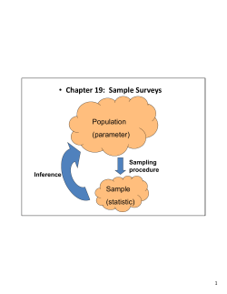
This is the ―black box‖ testing approach as illustrated in Figure 1. For our purposes, the test matrix
is pre-designed as the inputs, the physical experiment is performed inside the ―black box‖, and then
the output results are used to develop a statistical model of the ―black box‖ that replicates the
responses for a known set of inputs. This approach was first outlined by Breisig 9,10 and W. Cauer11
and later promulgated by E. Cauer 12 and Belevitch 13. A more modern treatment is presented by
Beizer14,15.
Figure 1: Conceptual sketch of the ―black box‖ model.
As illustrated in Figure 1, the inspector or researcher has no knowledge of the process inside the ―black box’, but
can control the inputs and analyze the outputs. The goal of the analysis is to represent the system inside the black
box with a surrogate model that represents the process in terms of characterizing its outputs. We now proceed to
present the statistical theory of the proposed theory and methodology.
Standard uses of OC curves in Statistical Quality Control (SQC) are used to establish sample sizes for specified
levels of quality parameters. Most of these techniques are graphical in nature and are cumbersome to use.
Additionally, the methods do not pose the question properly in terms of the requirements for the validation and
verification process for the simulation.
A technique based upon the Operating Characteristic 16,17 is employed to determine the sample size that
determines, a priori, the error tolerance based upon simultaneous specification of statistical Type I and Type II
errors. In so doing, the precision of the errors can be specified to a known tolerance in the design. Design of
Experiments18 (DoX) is employed to develop the statistical test matrices for the comparisons. Statistically-based
Analysis Of Variance19 (AVOVA) is used to analyze and interpret the results and to develop surrogate regression
equations. These surrogates are then used to develop response surfaces in order to assess and visualize the results.
III.
Theory
Type I and Type II Errors
Design of sampling plans for acceptance involves both Type I and Type II errors as well as a tolerance for
accepting a certain number of outliers in the batch. These sampling plans often use a statistical hypothesis that
assumes some characteristic about a parameter for a certain statistical population. The purpose of the testing is to
determine, to some level of probability of occurring or confidence, whether or not this assumption is true. The two
types of statistical hypotheses are
1) Null hypothesis. The null hypothesis, denoted by H0, is generally stated that there is likely to be no
association between an input variable(s) and its response. The null hypothesis is then interpreted that the
sample observations are likely to result purely from chance.
3
2) Alternative hypothesis. The alternative hypothesis, denoted by H1 or Ha, is the complement of the null
hypothesis and generally states there is likely to be an association between an input variable(s) and its
response. The alternative hypothesis is then interpreted that the sample observations are likely to be
influenced by some non-random cause.
Type I and Type II errors involve an incorrect interpretation of the null hypotheses.
To demonstrate how a Type I or Type II error may arise in hypothesis testing, consider that we wish to determine
if a coin is fairly balanced and tossed. The coin may be imbalanced or it may be tossed in a biased manner that may
favor the outcome of Heads or Tails. If neither the coin nor the tossing procedure is biased, we would expect an
equal number of Heads and Tails to be realized over a large enough number of trials. In hypothesis testing we
follow a procedure of four steps:
1) State the mutually exclusive null and alternative hypotheses in such a manner that they may be proven true
or false to a prescribed level of confidence.
2) Develop an analysis plan to describe how to use the acquired data to evaluate the null hypothesis. For
example, what statistical test and criterion level of null hypothesis rejection to use.
3) Perform the analysis of the sample data to determine the value of the test statistic detailed in the analysis
plan.
4) Assess and interpret the results by applying the decision rule described in the analysis plan. If the value of
the test statistic is not likely to have occurred by chance with respect to the null hypothesis, we reject the
null hypothesis in favor of the alternative hypothesis with a certain level of error tolerance.
In this situation, a null hypothesis might be that half the flips would result in Heads and half would result in Tails—
the ―50/50‖ outcome. The alternative hypothesis is simply stated ―otherwise‖ (i.e. it may be that the number of
Heads and Tails would be very different from 50/50). We state these hypotheses as
, and
1
Assume that the coin flipper then proceeds to flip the coin a large number of times, resulting in 15% Heads and
85% tails. Based upon that outcome it is very likely that either the coin or the tossing of the coin is biased. In
statistical parlance, we would say the null hypothesis ( ) of a fair coin toss is to be rejected in favor of the
alternative hypothesis (to a certain probability of being wrong). But what if the researcher misinterpreted the results
and made the wrong conclusion? These erroneous conclusions are referred to as decision errors, as opposed to
analysis or modeling errors, and are characterized as:
a)
Type I error. A researcher commits a Type I error if they reject a null hypothesis when it is likely to be
true. The probability of committing a Type I error is referred to as the significance level (α).
b) Type II error. A researcher commits a Type II error if they fail to reject a null hypothesis when it is likely
to be false. The probability of committing a Type II error is called Beta (β). The probability of not
committing a Type II error is called the Power of the test.
In our coin-tossing experiment, the researcher can make a decision to reject or fail to reject the null hypothesis when
the truth of the null hypothesisis known as presented in Table 1. For instance, if the researcher had failed to reject
the null hypothesis when it was true, they would have made a correct decision, as indicated in block ―A‖ of the
table. Likewise, if the researcher had failed to reject the null hypothesis when it was false, they would have
committed a Type II error, as indicated in block ―B‖ of the table, and likely passed a faulty product to the consumer.
On the other hand, if the researcher rejected the null hypothesis when it was true, they would have made an incorrect
decision and would have committed a Type I error, as indicated in block ―C‖ of the table and likely would have
discarded a good product. Finally, if the researcher had rejected the null hypothesis when it was false, as indicated
in block ―D‖ of the table, they would have made a correct decision.
Table 1. Description of error types in the interpretation of statistical
hypotheses. The green-highlighted boxes (labeled A and D) are correct
4
interpretations. The red-highlighted boxes (labeled B and C) are incorrect
interpretations.
Truth
H 0 is True
Fail to Reject H 0
(Accept)
A
Correct Decision with
probability (1- );
Related to AQL
Decision
Reject H 0
(Don't Accept)
H 0 is False
B
Wrong Decision:
Type II error
(consumer risk) with
probability ;
Related to LTPD
C
Wrong Decision:
D
Type I error (producer Correct Decision with
risk) with probability
probability (1- )
Producer Focus
Consumer Focus
In statistically-designed sampling plans, we attempt to simultaneously control Type I and Type II errors. The
Operating Characteristic (OC) curve offers the means by which the sample size may be determined with a priori
knowledge of Type I and Type II errors. Additionally, the OC curve approach allows the researcher to specify the
number of outliers or tolerable defects that he/she is willing to accept in the sampling plan.
Acceptance Sampling Plans
An acceptance sampling plan is part of Statistical Quality Control (SQC). In the acceptance process, a random
sample is taken from a population or lot and analyzed relative to some metric. The results of the analysis are used to
assess whether the lot will either be rejected or accepted. It is essentially a procedure for determining the fate of
sample lots without performing exhaustive inspection (e.g. 100%). The most widely used sampling plans are given
by Military Standard (MIL-STD-105E, replaced by MIL-STD-191620). Acceptance sampling plans are also useful
to determine the quality level of an incoming shipment or at the end of production and to determine whether quality
level is within the metric that has been predetermined. This technique is used when a single lot or a series of lots is
submitted for lot acceptance and a single sampling plan which limits Type I (producer rejecting good product) and
Type II (consumer accepting bad product) errors is desired. The procedure is frequently used by the producer of a
product before releasing the product to the customer and by a customer before said received product is accepted for
use.
There are several important characteristics of an acceptance sampling plan that help to predefine the likely
outcomes that are acceptable to the producer and the customer. The lot size (N) is used to characterize the
population that we wish to sample from. Typical values for N of 500 to 1000 are sufficiently large to establish a
population count. A pseudo-random sample of size (n) is drawn from the population (N) in order to characterize the
behavior of the population without the necessity of full testing. The acceptance number (c) establishes the number
of tolerable defects (outliers) per sample that is tolerable to the customer. The Acceptance Quality Level (AQL) is
the smallest percentage of defectives that will make the lot definitely acceptable (set by the customer). Lot
Tolerance Percent Defective (LTPD) is the quality level that is unacceptable to the customer. The number of
defectives actually found in a sample (d) is used to establish the quality of the sample relative to the acceptance
number (c). A typical flow of a Lot-by-Lot sampling plan is illustrated in Figure 2. The lot size (N) is established
from which a sample is drawn of size n and the number of defectives (d) are counted and compared against the
metric for acceptance (c)21. The decision is then made as to accept or reject the lot. It is the decision point where
Type I and/or Type II errors are committed.
5
Figure 2: Lot-by-lot sampling plan.
A distribution function is used to characterize the two outcomes of the decision (accept or reject) for many
sampling plans. Type ―A‖ OC curves give the probability of acceptance for an individual lot coming from finite
production22 in which the probability is influenced by the lot size and are mathematically characterized by the
hypergeometric probability distribution. Type ―B‖ Give the probability of acceptance for lots coming from a
continuous process in which the probability is not influenced by the lot size and are mathematically characterized by
the binomial probability distribution. The binomial distribution assumes that there are two possible outcomes to
each event, the outcomes are mutually exclusive, the events are independent, and the probability of the occurrence is
constant across events.
We will discuss only type ―B‖ OC curves in this investigation as we assume that there are a large enough
number of samples to be drawn in computational studies that we are effectively drawing samples with replacement.
We first note that there are a large number of ways that the defective item (d) may arise in a sample of size n
represented by
2
The binomial distribution then is good approximation for the smapling process outcome and is used to determine the
probability of finding d defectives in a sample of size n for a given parameter ―p‖, such as acceptable quality level
(AQL), is given as
3
Mathematically, the probability of acceptance ( ) is
{
}
∑ {[
]
}⇒
∑( )
4
The probability of finding the defect using a given sampling plan is related to the error type as well as the criterion
and sample size for a given number of defects. For example, relative to Figure 2 decision of accept/reject (d > c),
the binomial distribution for sample size n, acceptance level c, still requires additional information according to
Equation 4—namely the parameter p for quality and the number of defectives d determined from the sample. If we
sum over the possible number of defects from zero to c and specify the parameter p as well as the error tolerance
that we are willing to accept (Type I or Type II), we can then iteratively calculate the sample size n from Equation 4
to simultaneously conform to these specifications. This process can be performed graphically or numerically.
In order to demonstrate the process of sample plan determination, we first begin with the development of the
ideal operating characteristic curve. In the ideal lot acceptance plan, we have perfect knowledge and are therefore
6
never wrong. For example, suppose the Acceptable Quality Level (AQL) is set to a prescribed value percent defect
of
. This means that with 100% probability we always accept a sample lot with less than AQL
.
Conversely, with 0% probability we accept (we never accept) a sample lot with AQL
. For illustration
purposes, an ideal OC is developed with the following characteristics:
1) the probability density function from which to draw samples,
a.
We select the binomial distribution function as the relevant probability density function (PDF).
2) the Type I error level ( ),
a.
We select the typical value of 0.05.
3) the number of samples n to be drawn,
a.
We select an arbitrary number of 100, for demonstration purposes.
4) the acceptance level c,
a.
We select an arbitrary number of 5, for demonstration purposes.
The above-listed parameters are used to determine an Acceptable Quality Level (AQL) of 2.65%. This AQL will
also be used for the corresponding actual OC curve presented shortly.
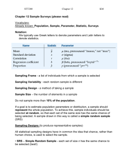
An ideal OC curve assumes perfect knowledge as well as perfect interpretation of the results of the inspection.
An ideal OC is illustrated in Figure 3. For the ideal OC, we are always correct in either accepting or rejecting the
sample. This is tantamount to saying that we are always correct, with no probability of being wrong. As illustrated
in the figure, we perfectly accept, with 100% probability, all samples with AQL 0.0265. Conversely, we perfectly
reject all samples with AQL
0.0265. In order to achieve this level of perfection, we must both have perfect
knowledge via total inspection (100% inspection) and interpret the results correctly (make no Type I or Type II
errors). The actual OC differs from the ideal OC by allowing for partial inspection as well as allowing for the
possibility of errors in the interpretation.
We accept with 100% probability
all samples with AQL 0.027.
“Good”
lots
―Indifference‖ region is zero. We
are always certain of decision
We accept with 0% probability (reject)
all samples with AQL 0.027.
AQL=0.027
“Bad” lots
Figure 3: Ideal Operating Characteristic (OC) curve. Parameters: =0, =0, nall, call, AQL=0.0265.
In reality, we are never likely to have total inspection and perfect interpretation of the results of the inspection.
The actual OC curve accounts for less-than-total inspection as well as allows for the possibility of incorrect
interpretation of the inspection results. A finite sample size n is selected to inspect and inspection standards for
error allowance are established via Type I and Type II error levels. The actual OC curve illustrated in Figure 4 was
developed for Type I error level ( ) of 0.05, Type II error level () of 0.05, and a binomial probability density
7
function with parameters n=100, and c=5. Label ―A‖ in the figure is the intersection of the (1-) line with the OC
curve and determines the Acceptable Quality Level (AQL) via the vertical intersection with the abscissa (Fraction
Defective). For the given parameters, the AQL is determined to be 2.7%. For the actual OC curve, we always have
a probability of incorrectly accepting or rejecting the sample. The actual OC differs from the ideal OC curve by
allowing for partial inspection as well as allowing for the possibility of errors in the interpretation.
A
B
We accept with (1-)
probability all samples with
AQL 0.027, with
significance. Correct decision.
(1-)
We reject with probability
all samples with AQL
0.027. Incorrect decision
(Type I error).
AQL = 0.027
Figure 4: Visual interpretation of correct and incorrect producer (Type I error) decisions. Operating Characteristic
(OC) curve for =0.05, =0.10, n=100, c=5, AQL=0.027.
Figure 4 presents important information and should be well interpreted. Label ―B‖ in the figure represents the
region of decision for the producer: to either accept or reject the lot. In this situation, the lot is not likely to be
defective. Label ―B‖ indicates the region of acceptance with Acceptable Quality Level (AQL) 2.7%. We accept
with (1-) = 0.95 probability all samples with AQL
0.027 at a significance of = 0.05. In other words, as
indicated by label ―B‖ in the figure, the producer is willing to accept an =5% probability of wrongly rejecting a
good sample and committing a Type I error (reference Table 1). This incorrect decision results in re-working the
product, scrapping the product, or similar follow up for a product that is, in fact, of acceptable quality. The result of
this incorrect decision is a waste of resources for the producer, both from the fact that they used resources to develop
and/or manufacture the product and will also incur further costs to dispose of or re-work the product. We now
discuss the OC curve in terms of the more egregious Type II or consumer error ().
In committing a Type II error, the producer has errantly released a product to the consumer while informing
them that the product meets quality standards. This is in contrast to the Type I error, where the product was not
released to the customer because it failed inspection. The OC curve illustrated in Figure 4 focused on Type I error
(producer). That figure is re-displayed in Figure 5, but now the focus is Type II error (consumer). Label ―C‖ in the
figure is the intersection of the line with the OC curve and determines the Lot Tolerable Percent Defective (LTPD)
via the vertical intersection with the abscissa (Fraction Defective). For the given parameters, the LTPD is
determined to be 9.1%.
8
We reject with (1-) probability all
samples with LTPD 0.091.
Correct decision.
We accept with % probability
all samples with LTPD 0.091.
Type II error.
E
D
Indifference
C
LTPD = 0.091
AQL
Figure 5: Visual interpretation of Type II error. Actual Operating Characteristic (OC) curve for =0.05, =0.10,
n=100, c=5, AQL=0.027, LTPD=0.091.
Figure 5 presents important information and should be well interpreted. Label ―D‖ in the figure represents the
region of decision for the customer or user: to either accept or reject the lot. In this region the lot has a high
probability of being defective. If the customer errantly accepts a bad lot- they have committed a Type II and are
now at risk by unknowingly using a potentially defective product. They commit this error with % probability. On
the other hand, if the customer rejects the lot, they have made the correct decision with (1-)% probability. In the
region of indifference, labeled ―E‖ in the figure, we have an insufficient level of confidence to assess the decision
from either the producer or consumer perspective. We now turn to typical interpretations and uses for the OC
curves.
In order to establish Type I error control, with reference to point ―A‖ in Figure 4, , we let the acceptance number
(c) and sample size (n) be unknown and set:
1) the probability of acceptance ( ) to (1- ) (point ―A‖ in Figure 4),
2) the quality parameter ( ), related to the fraction defective, to some value ( )
a.
The Acceptable Quality Level (AQL) is often used for
3) the number defective to vary over an integer range (typically 0 to 10 is reasonable, and always less than
or equal to acceptance number c).
In terms of the binomial distribution, the above criteria are represented via Equation 4 as 23
{
}
∑ {[
]
}
5
Equation 5 is often rewritten for graphical solution as
∑ {[
]
}
6
In order to establish Type II error control, with reference to point ―C‖ in Figure 5, we let the acceptance number
c and sample size n be unknown and set:
1) the probability of acceptance ( ) to
9
(point ―C‖ in Figure 5),
2) the quality parameter ( ), related to the fraction defective, to some value (
a.
the Lot Tolerable Percent Defective (LTPD) is often used for
)
,
3) the number defective to vary over an integer range (typically 0 to 10 is reasonable, and always less than
or equal to acceptance number c).
Similarly to Equation 5, in terms of the binomial distribution, the above criteria are represented via Equation 4 as
{
}
∑ {[
]
}
7
}
8
Equation 7 is often rewritten for graphical solution as
∑ {[
]
Note that Equations 5 and 7 represent different points on the same OC curve as specified by sample size n and
acceptance number c. They are related but independent. As such, they represent a system of equations for solving
for n and c. We will demonstrate this solution via two methodologies: graphically and then numerically.
Traditional Graphical Solution of Sampling Plan
The solution of the highly nonlinear, coupled Equations 6 and 8 is often performed graphically. The traditional
approach requires a nomograph that can simultaneously display the required information visually and clearly.
Figure 6 illustrates such a nomograph prepared for test and evaluation by Defense Acquisition University (DAU)24.
The figure is fairly complicated and requires some edification. The right axis of Figure 6 displays one of two
relations:
1) For Type I errors, it displays , or the right-hand-side of Equation 9, obtained from Equation 6 with
as
∑ {[
2) For Type II errors, it displays
as
]
}
9
or the right hand side of Equation 10, obtained from Equation 8 with
∑ {[
]
}
10
The left axis of Figure 6 displays the reliability of the sample or fraction that are not defective follows:
1) For Type I errors, it displays the parameter p associated with , called .
a. Often,
.
2) For Type II errors, it displays the parameter p associated with , called .
a. Often,
.
We now demonstrate the use of the nomograph by way of a numerical example solved graphically. Suppose we
are given the following parameter set: [
] and [ =LTPD=0.091;
]. With
reference to Figure 6, we outline the following procedure to identify the sampling plan, that is to say, the sample size
n and acceptance number c consistent with the given criteria. Note that the sampling plan (n, c) is an integer set.
10
1-p1= 0.973
𝛽 = 0.9
77
5
6
Solution
for (n,c)
= (100,5)
31
1-p2
= 0.909
4
21
Confidence (C) =1-[probability of up to c occurrences in n trials]
C = 1- == [Right-hand side of Equation 6 or 8]
Reliability (R) = 1-[fraction defective]
R = (1- p)
11
𝛼 = 0.05
Figure 6: Test and Evaluation binomial nomograph. Example: given (
; indicated
in red boxes and red line) and ( =LTPD=0.091;
indicated in dashed blue boxes and dashed blue line);
solution at intersection of two lines (indicated by black circle) gives n = 20 trials with c =5 failures. (Reference:
Defense Acquisition University (DAU) Program Managers Tool Kit, Fifteenth Edition, Ver 1.0.)
Step 1: Calculate the reliability
for the Type I error as
11
Step 2: Locate
on the left axis of the nomograph (labeled as item ―1‖ in Figure 6).
Step 3: Locate the confidence
on the right axis on the nomograph (labeled as item ―2‖ in Figure 6).
Step 4: Draw a straight line from
on the left axis to
red line and labeled as item ―3‖ in Figure 6).
Step 5: Calculate the reliability
on the right axis on the nomograph (represented by the
for the Type II error as
12
Step 6: Locate
on the left axis of the nomograph (labeled as item ―4‖ in Figure 6).
Step 7: Locate the confidence
11
on the right axis on the nomograph (labeled as item ―5‖ in Figure 6).
Step 8: Draw a straight line from
on the left axis to
blue dashed line labeled as item ―6‖ in Figure 6).
on the right axis on the nomograph (represented by the
Step 9: The intersection of the two straight lines in step 4 and step 8 is the sample plan (i.e. solution) for the
given parameters (labeled as item ―7‖ in Figure 6 and indicated marked by the black circle).
The graphical approach to determine the sample plan is approximate. Additionally, as n and c must be integers, the
solution is considered to be one in the ―nearest family‖ of intersections. For example (n,c) = (101,5) is just as likely
to be an approximate solution. It is usually recommended to increase the acceptance number slightly rather than to
increase the sample size, as samples are typically more expensive to obtain. We now present an alternative
graphical approach to the nomograph that illustrates the feasible sample plans more dramatically than the
nomograph approach.
Modified Graphical Solution of Sampling Plan
We now represent a more visually powerful graphical approach to the determination of the sampling plan for the
simultaneous solution of Equations 5 and 7. A numerical algorithm was developed in MATLAB for this solution
and visualization. First, Equations 5 and 7 were rewritten in the method of root solving by placing all terms on the
left side of the equation and setting the resulting equations to zero. Respectively, modified Equations 5 and 7 for
and
become
∑ {[
∑ {[
]
]
}
}
13
14
Equations 13 and 14 are now parameterized for relevant values of possible sampling plan solutions (n,c). For
example, suppose n varied from 1 to 200 and c varied from 0 to 20. Recall that (n,c) must be constrained to an
integer-only solution set and that n > c. Note also that the summations in Equations 13 and 14 represent the
binomial cumulative probability density function. We present the graphical technique in three parts. First, the
visualization of Equation 13 is presented for Type I error characterization, then the visualization of Equation 14 is
presented for Type II error characterization, then the combined solution set is visualized simultaneously.
The first step in the modified graphical solution to the sampling plan (n,c) is to solve Equation 13 for a given
( , ). The sample size n and acceptance number c are allowed to vary over relevant ranges and the summation in
Equation 13 is calculated and the function value
is determined. The resulting data set is plotted in
three dimensional space with the sampling plan inputs (n,c) as the independent variables and the value of the output
of Equation 13 as the response. Valid solutions will satisfy Equation 13 with a value of 0. Infeasible solutions will
be not equal to zero. In this manner, it is easy to visualize the behavior of the Type I error behavior. The results of
this procedure are presented in Figure 7. The visual results illustrated in Figure 7 are quite powerful. Presented
implicitly is the risk of incorrectly setting up the sampling plan. The presentation of risk in Table 1 is re-represented
in Table 2 with the focus on Type I error only.
12
𝑓 𝛼 𝑝 𝑛 𝑐 , [value of Equation 13]
Invalid Valid Type I solution
region: 𝑓 𝛼 𝑝 𝑛 𝑐
C
Valid Type I solution
region: 𝑓 𝛼 𝑝 𝑛 𝑐
𝑛𝑐
A
Figure 7: Visualization of Type I error behavior. Given (
for various sampling
plans (n,c). Valid sampling plan regions clearly visible as plateau where solution of
.
Similarly, invalid sampling plan regions clearly visible as rising ridge where solution of
. Red
line represents sample plans (n,c) consistent with only Type I error control (red line from Figure 6, step 3).
Table 2. Type I risk associated with sampling plan (n,c) in the interpretation of
statistical hypothesis. The green-highlighted box (labeled A) is correct
interpretation and likewise labeled in Figure 7. The red-highlighted box (labeled
C) is incorrect interpretation and likewise labeled in Figure 7.
Truth
Fail to Reject H 0
(Accept)
Decision
Reject H 0
(Don't Accept)
H 0 is True
A
Correct Decision with
probability (1- );
Related to AQL
C
Wrong Decision:
Type I error (producer
risk) with probability
Producer Focus
With combined reference to Table 2 and Figure 7, we note that the valid region in Figure 7 is the correct decision
from Table 2. This means that we can, to at least (
) probability, state that the valid sampling plans will allow
the correct conclusions to be drawn from the results obtained with the valid sampling plans. The nomographobtained sampling plan (n,c) =(100,5) from Figure 6 is presented in Figure 7 for comparison and is labeled with the
black circle. Also, for comparison purposes, the red line represents sample plans (n,c) consistent with only Type I
error control (red line from Figure 6, step 3). Conversely, invalid sampling plans, while still possible to implement,
will likely lead you to the wrong producer-related conclusion from your results. This is, therefore, extremely
important guidance for establishing design of sampling plans. It is, however, incomplete as it only relates Type I
error reduction. For the more complete picture of risk-reduction, we need to include Type II error behavior.
We next study Type II error behavior independently of Type I error behavior in a similar manner to the
development of Type I error behavior illustrated in Figure 7 and presented in Table 2. The first step in the modified
13
𝑔 𝛽 𝑝 𝑛 𝑐 , value of Equation 14
graphical solution to the sampling plan (n,c) is to solve Equation 14 for a given
. The sample size n and
acceptance number c are allowed to vary over relevant ranges and the summation in Equation 14 is calculated and
the function value
is determined. The resulting data set is plotted in three dimensional space with the
sampling plan inputs (n,c) as the independent variables and the value of the output of Equation 14 as the response.
Valid solutions will satisfy Equation 14 with a value of 0. Infeasible solutions will be not equal to zero. In this
manner, it is easy to visualize the behavior of the Type II error behavior. The results of this procedure are presented
in Figure 8.
Invalid Type II error
solution region:
𝑔 𝛽 𝑝 𝑛𝑐
B
Valid Type II
error solution
region:
𝑔 𝛽 𝑝 𝑛𝑐
𝑛𝑐
D
Figure 8: Visualization of Type II error behavior. Example: given ( =LTPD=0.091;
) for various
sampling plans (n,c). Valid sampling plan regions clearly visible as plateau where solution of
.
Similarly, invalid sampling plan regions clearly visible as rising ridge where solution of
. Red
line represents sample plans (n,c) consistent with only Type II error control (blue dashed line from Figure 6, step
6).
With combined reference to Table 3 and Figure 8, we note that the valid region in Figure 8 is the correct decision
from Table 3. This means that we can state, to at least (
) probability, that the valid sampling plans will allow
the correct conclusions to be drawn from the results obtained with the valid sampling plans. The nomographobtained sampling plan (n,c) =(100,5) from Figure 6 is presented in Figure 7 for comparison and is labeled with the
black circle. Also, for comparison purposes, the red line represents sample plans (n,c) consistent with only Type II
error control (blue dashed line from Figure 6, step 6). Conversely, invalid sampling plans, while still possible to
implement, will likely lead you to the wrong consumer-related conclusion from your results. This is, therefore,
extremely important guidance for establishing design of sampling plans. It is, however, incomplete as it only relates
Type II error reduction. For the most complete picture of risk-identification, we need to combine Type I and Type II
error behaviors. This combined approach is analogous to the tradition nomograph approach but is much more
visually intuitive in that allows one to see the relative risk regions concomitantly.
14
Table 3. Type II risk associated with sampling plan (n,c) in the interpretation of
statistical hypothesis. The green-highlighted box (labeled D) is correct
interpretation and likewise labeled in Figure 8. The red-highlighted box (labeled
B) is incorrect interpretation and likewise labeled in Figure 8.
Truth
Fail to Reject H 0
(Accept)
Decision
Reject H 0
(Don't Accept)
H 0 is False
B
Wrong Decision:
Type II error
(consumer risk) with
probability ;
Related to LTPD
D
Correct Decision with
probability (1- )
Consumer Focus
We now present the combined Type I and Type II error behaviors. A numerical algorithm was developed in
MATLAB for this solution and visualization. Since Equations 13 and 14 are independent formulations for zero,
they are linearly superposed with no modification to the solution. Performing this operation gives
15
Substituting the functions for
into Equation 15 yields
and
[
from Equations 13 and 14, respectively,
∑ {[
]
}]
16
[
∑ {[
]
}]
The combined parameter set
is now used to develop the response
and visualized in a manner similar to the individual Type I and Type II error visual representations in Figures 7 and
8, respectively.
With combined reference to Table 1 and Figure 9, we note that the invalid Type I region, to at least
probability, is similar, but not identical, to the equivalent region from Figure 7. Likewise, the invalid Type II region,
to at least probability, is similar, but not identical, to the equivalent region from Figure 8. These regions are very
evident in Figure 9 by the dominant ridges, again labeled as ―C‖ for Type I invalid region and ―B‖ for Type II
invalid region. The combined Type I and Type II correct decision region, in which
, is
identified in Figure 9 by the black-dashed trapezoidal region and labeled ―A+D‖. From Table 1, the interpretation is
that, to a combined (
) probability of not making a Type I error and (
) probability of not making a Type II
error, the proposed sampling plan will allow the correct conclusions to be drawn from the results. We now turn to
the numerical solution of the determination of the sampling plan.
Invalid Type II error
solution region:
𝑔 𝛽 𝑝 𝑛𝑐
15
Invalid Type I error
solution region:
𝑓 𝛼 𝑝 𝑛 𝑐
B
C
𝑛𝑐
Valid Type I & Type II
error solution region:
𝛼 𝑝 𝛽 𝑝 𝑛𝑐
A+D
Figure 9: Visualization of simultaneous Type I and Type II error behavior. Given (
=LTPD=0.091;
for various sampling plans (n,c). Valid sampling plan region clearly visible as
depressed ―valley‖, outlined by black-dashed trapezoid and labeled ―A+D‖, where solution of
. Similarly, invalid sampling plan regions are everywhere else where
. The red circle represents sample plan (n,c) consistent with both Type I and Type II
error control (black circle from Figure 6, step 7).
Numerical Solution for Sampling Plan
The graphical approaches presented earlier are only approximate, and have further drawbacks of requiring the
charts and/or figures in order to determine the sampling plans for a known Type I and Type II error probability. We
therefore seek a more portable and accurate procedure for determining the sampling plan for a desired set of
parameters. The process is similar to that which produced Equation 16. We begin with the building blocks for Type
I and Type II errors from Equations 13 and 14, respectively. The objective function is developed using the method
least squares minimization as
[
]
[
]
17
Subject to the constraints:
18
19
20
21
22
23
24
16
For completeness, the Type I and Type II error functions are substituted from Equations 13 and 14, respectively, into
Equation 17. Additionally, an error tolerance ( ) for numerical convergence is used to obtain
[
∑ {[
]
}]
25
[
∑ {[
]
}]
Theoretically, the solution to Equation 25 should yield as close to zero if a feasible sample plan (n,c) can be found
consistent with specified values of the input parameters
. This is analogous to finding the graphical
solution via Equation 16 and Figure 9 or the nomograph from Figure 6. Equation 25 along with the constraints
given by Equations 18 to 24 was programmed in MATLAB and solved consistent with the sample plan bounds n = 0
to 200 and c = 0 to 20. The numerical value of the objective function obtained is 1.68e-7 with parameters
and the resulting sampling plan is (n,c)=(100,5). This numerical solution
is exactly the same as that obtained via the graphical nomograph and newly-introduced multidimensional graphical
approach.
The sampling plan is now shown to be related to the Type I error ( ) and Type II ( ) error along with an
acceptance number c compared to the actual number of defectives d in a sample lot and required sample size n by
means of the operating characteristic (OC) curve and its graphical and numerical variants. It is important to
recognize that just because there are several methodologies available for determination of sampling plans, none of
them guarantee that a sampling plan actually exists for a given set of parameters
. Indeed, that is
actually the aim of the process—that is to say, if a sampling plan does not exist for the given set of parameters, then
we may not specify the answer to the problem with the desired simultaneous Type I and Type II confidence and
must seek an alternative sampling plan and/or relax our parameter set.
IV.
Conclusions
The statistically-based process for the number of simulation runs to perform, given by sample size (n), and
acceptance number (c) supports error control and Uncertainty Quantification (UQ) analyses. By establish
confidence intervals on the parameters to be validated, experimental procedures may be aligned to the modeling &
simulation (M&S) process. Conversely, with knowledge of the uncertainty in the experimental data and/or
processes, the experimental results will be a better guide for proper M&S data reporting and validation of results.
The sampling plan was shown to be related to the Type I error ( ) and Type II ( ) error along with an
acceptance number (c) compared to the actual number of defectives (d) in a sample lot and required sample size (n)
by means of the operating characteristic (OC) curve and its graphical and numerical variants. The uncertainty
associated with the results is bounded and probabilistically controlled by the specification of the confidence
parameters
as well as the Acceptable Quality Level (AQL) and Lot Percent Tolerable Defective (LPTD). In
so doing, the producer or developer as well as the purchaser or user has a known probability of releasing and/or
obtaining a defective product. In computational analyses, these defectives are outliers for which there is no apparent
cause. We can control the rejection of these outliers by specifying the acceptance number (c) to a number that we
can tolerate for our level of risk.
It is important to recognize that just because there are several methodologies available for determination of
sampling plans, none of them guarantee that a sampling plan actually exists for a given set of parameters
. Indeed, the process of establishing if a sampling plan exists for a given set of parameters allows us to
specify the answer to the problem with the desired simultaneous Type I and Type II confidence. The problem that
many inexperienced practitioners have in implementing this process is that they only deal with one error type or the
other (typically using only Type I) and therefore miss the bigger picture and expose the results to a greater amount
of uncertainty and/or lack-of-confidence in the results. This almost always leads to a greater level of acceptance of
results that are actually not validated and therefore almost always requires additional testing than actually required.
Properly specifying sampling plans and risk levels before testing will result in the lowest number of samples
required and therefore lowest cost for an experimental test program.
17
V.
Future Work
The methodology presented herein will be incorporated into a statistically-based modeling & simulation (M&S)
validation plan that incorporates experimental results as well as analytical solutions for comparison. Uncertainty
Quantification (UQ), Sensitivity Analysis (SA), Design of Experiments (DoX), and advanced statistical analysis are
part of the new validation process. Comparisons of results from the new process will be performed against the more
traditional validation process.
VI.
Acknowledgements
The author gratefully acknowledges the financial and technical support of the US Air Force for sponsoring this
research. Specifically, from the Air Vehicles Directorate: Dr. José Camberos, Multidisciplinary Science and
Technologies Center (AFRL/RBSD); from the Office of Scientific Research (AFOSR), Dr. Fariba Fahroo, Program
Manager/Computational Mathematics under LRIR # 11RB05COR; and from the Propulsion Directorate, Energy and
Power Systems Branch (AFRL/RZP): Dr. Kirk Yerkes; Dr. Mitch Wolff, and Mr. Peter Lamm.
VII.
1
References
Mandel, J., (1964), The Statistical Analysis of Experimental Data, New York, Dover Publications.
The National Institute of Standards and Technology (NIST), NIST/SEMATECH Engineering Statistics Handbook,
available for download: http://www.nist.gov/itl/sed/gsg/handbook_project.cfm
3
Allchin, D. (Spring 2001). "Error Types". Perspectives on Science 9 (1): 38–58.
4
Doty, Leonard A. (1996) Statistical Process Control. New York, NY: Industrial Press INC.
5
DeLoach, R., ―Propagation of Computational Uncertainty Using the Modern Design of Experiments,‖ North
Atlantic Treaty Organization Research (NATO) and Technology Organization (RTO) Applied Vehicle Technology
(AVT) Specialists’ Meeting on Computational Uncertainty in Military Vehicle Design – RTO-MP-AVT-147, Paper
No. 64.
6
DeLoach, R. (2000). Improved Quality in Aerospace Testing Through the Modern Design of Experiments (Invited)
AIAA 2000-0825. 38th AIAA Aerospace Sciences Meeting and Exhibit, Reno, NV, USA.
7
DeLoach, R. (1998). Applications of Modern Experiment Design to Wind Tunnel Testing at NASA Langley
Research Center. AIAA 98-0713. 36th Aerospace Sciences Meeting and Exhibit, Reno, NV, USA.
8
JCGM 200:2008: International Vocabulary of Metrology — Basic and general concepts and associated terms
(VIM), document produced by Working Group 2 of the Joint Committee for Guides in Metrology (JCGM/WG 2).
Available electronically: http://www.bipm.org/utils/common/documents/jcgm/JCGM_200_2008.pdf.
9
Breisig, F., Theoretische Telegraphie, Braunschweig, F. Vieweg und Sohn, 1910.
10
Breisig, F, Method and Arrangement for Determining Crosstalk in Multicircuit Systems, US patent 492 034, filed
13 Aug 1921, issued 30 Jun 1925.
11
Cauer, W., Theorie der linearen Wechselstromschaltungen, Vol.I. Akad. Verlags-Gesellschaft Becker und Erler,
Leipzig, 1941.
12
Cauer ,E., Mathis, W., and Pauli, R., "Life and Work of Wilhelm Cauer (1900 – 1945)", Proceedings of the
Fourteenth International Symposium of Mathematical Theory of Networks and Systems (MTNS2000), p4,
Perpignan, June, 2000.
13
Belevitch, V, "Summary of the history of circuit theory", Proceedings of the Institute of Radio Engineers (IRE),
vol 50, Iss 5, pp.848-855, May 1962.
14
Beizer, B., (199) Black-Box Testing: Techniques for Functional Testing of Software and Systems. ISBN
0471120944
15
Beizer, B., (1995) Black Box Testing. New York: John Wiley & Sons, Inc.
16
Ferris, C.L., Grubbs, F.E., Weaver, C.L., ―operating Characteristic Curves for the Common Statistical Test of
Significance,‖, Annals of Mathematical Statistics, June 1946.
17
Six Sigma Glossary, online statistical dictionary, http://www.micquality.com/six_sigma_glossary/oc_curve.htm.
18
Montgomery, D.C., (2009), Design and Analysis of Experiments, 7th Edition, New York, John Wiley & Sons.
19
Deep, R., (2006), Probability and Statistics, Boston, Elsevier Inc.
20
MIL-STD-1916, "DoD Preferred Methods for Acceptance of Product" (referenced 19 May, 2011, available online
at http://www.variation.com/techlib/standard.html).
21
Squeglia , N L, Zero Acceptance Number Sampling Plans, Fifth Edition, ASQ Press, ISBN 978-0-87389-739-6.
2
18
22
Human, S. W. and Graham, M. A. (2008). Average Run Lengths and Operating Characteristic Curves.
Encyclopedia of Statistics in Quality and Reliability.
23
Montgomery, D. C. (1996, p.620), Introduction to Statistical Quality Control (3rd ed.), New York: Wiley.
24
Schied, Charles F., Program Managers Tool Kit, Fifteenth Edition (Ver 1.0), Defense Acquisition University
(DAU), April 1, 2009. Available via DAU Web site: http://www.dau.mil/pubs/misc/toolkit.asp .
19


© Copyright 2026