
MANUAL OWNER’S 2014
2014
OWNER’S
MANUAL
1000cc Kohler Diesel
750 EFI Kohler Gas
UTVRevised 12-16-2013
Owner Memo
Name:_____________________________________
Purchasing Date:_____________________________
Type:______________________________________
Pin Number: ________________________________
Special Notice: ______________________________
Key Number: ________________________________
PAGE 2
OWNER’S MANUAL
Table of Contents:
Title............................ Page Number
Introduction.......................................................Page 4
Definitions.........................................................Page 4
Safety Labels................................................Pages 4-8
ROPS and FOPS Inspection Guide.............. Pages 9-10
General Safety...........................................Pages 11-14
Safe Riding Gear.............................................. Page 15
Features, Controls and Operation.............Pages 16-32
New Vehicle Break-in.......................................Page 33
Service and Maintenance......................... Pages 34-61
Storing and Maintaining Appearance....... Pages 62-63
Transporting your Intimidator..........................Page 64
Accessories.....................................................Page 64
Specifications...........................................Pages 65-70
Troubleshooting........................................Pages 72-77
Warranties................................................Pages 78-81
Service Record.........................................Pages 82-83
Training Certificate...........................................Page 84
Safety Checklist...............................................Page 85
PAGE 3
INTRODUCTION
READ THIS OWNER’S MANUAL. The Intimidator is and offroad vehicle and is not a toy. The Intimidator is an adult
vehicle only and can be hazardous to operate. Failure to
follow the warnings and instructions in this manual can
result in severe injury or death.
PIN NUMBER:
Product Identification Number is located
between the seat back and cargo bed.
DEFINITIONS
DANGER:
A Danger indicates a hazardous situation that, if not
avoided, may result in serious injury or death.
WARNING:
A Warning indicates a situation that, if not avoided, may
result in property damage.
Notice
A Notice indicates a situation that could result in property damage.
SAFETY
LABELS
For your protection, warning labels have been placed
on the vehicle. Read and follow the instructions of the
labels on the vehicle carefully. If any label becomes
illegible or comes off, contact your authorized dealer
to purchase a replacement.
Discretionary and Age Warning – Located on vehicle dash.
PAGE 4
OWNER’S MANUAL
DANGER:
Improper Use of Off-Highway Vehicles Can Cause
Severe Injury or Death
Drive Responsibly
Avoid loss of control and rollovers:
• Avoid abrupt maneuvers, sideways sliding, skidding, or
fishtailing, and never do donuts.
• Slow down before entering a turn.
• Avoid hard acceleration when turning, even from a stop.
• Plan for hills, rough terrain, ruts, and other changes in
traction and terrain. Avoid paved surfaces.
• Avoid side hilling (riding across slopes).
Require Proper Use of Your Vehicle
Do your part to prevent Injuries:
• Do not allow careless or reckless driving.
• Make sure operators are 16 or older with a valid drivers
license.
• Do not let people drive or ride after using alcohol or
drugs.
• Do not allow operation on public roads (unless
designated for off-highway vehicle access) – collisions
with cars and trucks can occur.
• Do not exceed seating load capacity.
Seat belt and Safety Warning – Located on vehicle firewall.
DANGER:
Operator and passengers must fasten seatbelt and both safety cab
nets while the vehicle is in use. Safety cab net must remain tight at
all times and not be damaged. If safety cab net is damaged or shows
significant wear, do not use vehicle until a new safety net is installed.
PAGE 5
Improper Use of Off-Highway Vehicles Can
Cause Severe Injury or Death.
Be Prepared:
•
•
•
•
Fasten seat belts.
Wear an approved helmet and protective gear.
Fasten side safety nets.
Each rider must be able to sit with back against seat,
feet flat on floor (and foot rests), and have hands on
steering wheel or handhold(s), where equipped. Stay
completely inside the vehicle.
Be Sure Riders Pay Attention and Plan Ahead
If you think or feel the vehicle may tip or roll, reduce your
risk of injury:
•
•
•
Keep a firm grip on the steering wheel or hand-holds
and brace yourself.
Do not put any part of your body outside of the vehicle
for any reason.
ROHVA and ISO certification sticker – Located on the
ROPS.
PAGE 6
OWNER’S MANUAL
Cargo Bed Safety Warning– Located in the cargo bed.
Improper use of cargo bed or cage/frame can result in
severe injury or death from loss of control, overturn or
other accidents.
• Never carry passengers in the cargo bed.
• Classic and Truck-Series maximum cargo bed capacity
is 1200 lb.
• Crew-Series maximum cargo bed capacity is 1000 lb.
• Do not exceed 10mph when cargo bed is loaded over
200 lb.
• Inflate tire pressure to pressures stated on tire pressure
label (Page 8).
• Secure cargo so that it will not shift, affecting handling
or cause the cargo to strike occupants.
• Keep cargo weight centered in the bed and low as
possible to reduce the chance of rollover.
• Do not tow or pull objects from any other point on the
vehicle other than the trailer hitch to winch if installed.
• Reduce speed when making turns.
• Avoid steel inclines and tough terrain.
• Read your Owner’s Manual before loading, towing or
pulling objects.
Tilt Cargo Bed Warning – Located near the handle on the
driver’s side of the cargo bed.
PAGE 7
WARNING
Keep hands, body, and other people away from
pinch points when lowering bed.
Do not hold the cage/frame while closing bed.
Tire Pressure Chart
TIRE PRESSURE AND SIZE CHART
Vehicle
Size
Position
Load
Air
Top Speed Rating
Rating (lb) Pressure (psi) (mph) @ Max Load
Front27x10R14 750
18
10
Rear
27x12R141275
22
10
Front27x10R14 680
12
35
Rear
12
35
27x12R141000
Max
Payload
Loaded
Unloaded
Clutch Cover Warning (some 750EFI models only) –
Located on the CVT clutch cover.
WARNING
Cover can become hot during and after operation.
PAGE 8
OWNER’S MANUAL
Rollover Protective
Structures (ROPS)
Inspection Guide
Falling Object
Protective Structures
(FOPS) Inspection
ROPS and FOPS, like any other safety device, need to
be periodically inspected to verify that the integrity of
the device has not been compromised through normal
machine use, misuse, age degradation, modifications,
or roll-overs.
Some mechanical discretion is essential, therefore
personnel who inspect ROPS and FOPS need to
comprehend and understand the significance of issues
like structural corrosion, cracks, and deformation.
Conservatism is the essential rule – if in doubt,
remove the machine from service and contact the
ROPS/FOPS manufacturer for assistance. Certain
conditions will absolutely render the ROPS/FOPS
unusable, examples are:
• Permanent deformation or twisting.
• Missing, damaged, or loose mounting hardware.
• Mounting hardware that is of a grade lesser than
specified.
• Any cracks in the structure (structural members
and/or welds).
• Significant corrosion.
• Modifications, i.e. unauthorized welds and holes.
• Missing or unreadable ROPS/FOPS label.
• Applicable ROPS/FOPS/machine model not
specified on the ROPS/FOPS label.
• Vehicles GVW (including attachments, restrained
payload, fuel and operator) in excess of the
maximum weight specified on the ROPS label.
• Missing seatbelts.
• Any unauthorized repair.
• Incomplete/improper installation.
PAGE 9
Other conditions may require imminent service
but may not render the unit immediately unusable,
examples are:
• Faded paint.
• Faded, hard to read ROPS/FOPS label.
• Slightly corroded mounting hardware.
ROPS/FOPS must be inspected immediately after any
type of collision, rollover or impact. If any damage
is evident, the ROPS/FOPS must be removed from
service, repaired and/or replaced.
When a ROPS/FOPS is removed or reinstalled,
mounting hardware must be examined for signs of
over stressing. Damaged mounting hardware must be
replaced with proper specification hardware before
placing the ROPS/FOPS back in service.
Properly maintained seatbelts are essential to
compliment the operator crush protection designed
into the ROPS. All seatbelt and/or seatbelt anchorage
systems that show evidence of cuts, fraying or wear,
significant discolorations due to exposure to the
elements, heavily soiled especially with oil, grease,
or fuel, or any type of damage must be immediately
replaced, regardless of age.
Operators are to be instructed to properly adjust and
use seatbelts at all times.
Make sure all latches are secure and safety cab net is
tight before operating the vehicle.
PAGE 10
OWNER’S MANUAL
GENERAL SAFETY
Never Operate:
• If you are under age 16 or without a valid driver’s
•
•
•
•
•
•
•
license.
At speeds too fast for your skills or conditions.
After or while using Alcohol or Drugs.
On hills steeper than 15 degrees.
On public roads or paved surfaces.
With more than two passengers (five for crew models),
or passengers who are under age 12, or may be too
young to reach grab handles.
With passengers in cargo box.
With non-approved accessories or modifications-they
may seriously affect stability.
ALWAYS:
• Wear your seatbelt. Vehicle rollover could cause death
or serious injury.
• Make sure all latches are secure and safety cab net is
tight before operating the vehicle.
• Wear a helmet and eye protection.
• Reduce speed and use extra caution while carrying
passengers.
• Avoid sharp turns or turns while applying heavy
throttle.
• Operate slowly in reverse – avoid sharp turns or
sudden braking.
• Make sure passengers read and understand all safety
labels.
Operator Safety
• Operator and passengers must fasten seatbelt and
•
•
both safety cab nets while the vehicle is in use.
Safety cab net must remain tight at all times and not
be damaged. If safety cab net is damaged or shows
significant wear, do not use vehicle until a new safety
net is installed.
Never operate your vehicle in fast-flowing water or
in water deeper than the floorboard. It may void the
warranty. Wet brakes may have reduced stopping
ability. Test your brakes after leaving water. If
necessary, apply them lightly several times to let
friction dry out the pads.
Check terrain before attempting to climb a hill. Never
PAGE 11
•
•
•
•
•
•
•
•
•
•
climb hills with excessively slippery or loose surfaces.
Never open the throttle suddenly or make sudden gear
changes. Never go over the top of a hill at high speeds.
Always use the proper size and type of tires specified
in this manual. Always maintain proper tire pressure as
specified on safety labels
Never modify this vehicle through improper installation
or use of accessories
Never exceed the stated load capacity for this vehicle.
Cargo should be properly distributed and securely
attached. Reduce speed and follow the instructions in
this manual for hauling cargo or pulling a trailer. Allow
greater distance for braking.
Always put the vehicle in Park before getting out of the
vehicle.
Always stop the engine before refueling. Remove
flammable material containers from the cargo box
before filling them with fuel. Make sure the refueling
area is well ventilated and free of any source of flames
or sparks. Gasoline is very flammable.
Always remove the ignition key when the vehicle is
not in use to prevent unauthorized use or accidental
starting.
Exhaust system components are very hot during and
after use of the vehicle. Hot components can cause
burns and fire. Do not touch hot exhaust system
components. Always keep combustible materials away
from the exhaust system. Use caution when traveling
through tall grass, especially dry grass. Never start the
engine or let it run in an enclosed area.
Do not carry a passenger until you have at least two
hours of driving experience with the Intimidator.
Always keep hands and feet inside the vehicle at all
times.
Always inspect the vehicle before each use to make
sure it’s in safe operating condition. Follow inspection
procedures described in this manual.
Operating a Damaged Vehicle
Operating a damaged vehicle can result in an accident.
In case of an overturn or other accident, have a qualified
service dealer inspect the entire machine for possible
damage, including (but not limited to) brakes, throttle and
steering systems.
PAGE 12
OWNER’S MANUAL
Operating at Excessive Speeds
Operating this vehicle at excessive speeds increases the
operator’s risk of losing control.
Operating on Pavement
This vehicle’s tires are designed for off-road use only,
not for use on pavement. Operating this vehicle on paved
surfaces may cause quick tire wear and may adversely
affect the handling of the vehicle and could result in loss of
control, accident or overturn. Avoid operating the vehicle
on pavement. If it’s unavoidable, travel slowly and avoid
sudden turns or stops.
Turning Improperly
Turning improperly could cause loss of traction, loss
of control, accident or overturn. Always follow turning
procedures for turning. Never turn abruptly or at sharp
angles. Never turn at high speeds. Never abruptly accelerate
while turning.
Jumps and Stunts
Attempting wheelies, jumps and other stunts increase the
risk of an accident or overturn. Never attempt wheelies,
jumps or other stunts. Avoid exhibition driving.
Improper Hill Climbing
Climbing hills improperly can cause loss of control or
vehicle overturn. Do not climb a hill or drive down a hill over
15 degrees.
Stalling While Climbing a Hill
Stalling or rolling backwards while climbing a hill could
cause an overturn. Always maintain a steady speed when
climbing a hill.
If all forward speed is lost:
• Apply the brakes. Place the transmission in reverse and
slowly allow the vehicle to roll straight downhill while
applying light brake pressure to control speed.
PAGE 13
If you begin rolling downhill:
• Never apply engine power. Apply the brakes gradually
until the vehicle is fully stopped. Place the transmission
in reverse and slowly allow the vehicle to roll straight
downhill while applying light break pressure to control
speed.
Improper Tire Maintenance,
Type or Size
Operating this vehicle with improper tire size or type may
void the warranty. See your dealer for details. Operating
this vehicle with uneven or low tire pressure could cause
loss of control or accident. Always use the size and type of
tires specified for your vehicle. Always maintain proper tire
pressure as described in the owner’s manual and on the
safety labels.
Equipment Modifications
We strongly recommend that consumers do not install any
after-market equipment that may increase the speed or
power of the vehicle, or to make any other modifications
to the vehicle for these purposes. Any modifications to the
original equipment of the vehicle create a substantial safety
hazard and increase the risk of bodily injury.
The warranty of the Intimidator will be terminated if any
unauthorized equipment has been added to the vehicle, or
if any modifications have been made to the vehicle, that
increase the speed or power.
The addition of certain accessories, including (but not
limited to) mowers, blades, large tires, sprayers, or large
racks, may change the handling characteristics of the
vehicle. Use only factory approved accessories, and
familiarize yourself with their function and effects on the
vehicle.
PAGE 14
OWNER’S MANUAL
SAFE RIDING GEAR
Always wear appropriate clothing when riding the
Intimidator. Wear protective clothing for comfort and
to reduce the chance of injury.
Helmet
Wearing a helmet can prevent a severe head injury.
Whenever riding the Intimidator or any Utility Vehicle,
always wear a helmet that meets or exceeds established
DOT (U.S. Department of Transportation) safety standards.
Eye Protection
Do not depend on eyeglasses or sunglasses for eye
protection. Always wear shatterproof goggles or use a
shatterproof helmet face shield.
Gloves
Wear gloves for comfort and for protection from sun, cold
weather and other elements.
Boots
Wear sturdy footwear. Do not drive or ride vehicle with bare
feet.
Clothing
Wear long sleeves and long pants to protect arms and legs.
PAGE 15
FEATURES, CONTROLS
and OPERATION
Ignition Key
Your key is a series type key, of which there are a high
range of numbers. It is highly recommended that you
obtain additional copies of your key. If all keys are lost, a
replacement ignition switch must be installed.
Starting the Kohler 1000 Diesel
Diesel vehicles have glow plugs that have to warm up. To
start the diesel engine, turn the ignition on and wait three
seconds before cranking the engine.
Starting the Kohler 750 EFI
For the best throttle response and performance, allow
the gas engine to idle for one minute after each cold start
before giving the vehicle acceleration.
Instrument Cluster
Your Intimidator is equipped with an analog speedometer
and a digital LCD screen. High pressure water or soap
may damage components. The LCD screen will display the
following:
• Seat Belt Reminder
• Gear Indicator – Displays the gear shifter position.
P – Park
R – Reverse
N – Neutral
L – Low Gear
H – High Gear
PAGE 16
OWNER’S MANUAL
• Battery Voltage Meter – Measures the amount of
•
•
•
•
•
power in the battery. Normal operating range is
between 12.8 and 14 volts.
Fuel Gauge – Shows the level of fuel in the fuel tank.
When the tank is full, all bars will be shown black.
RPM - Engine Revolutions Per Minute.
Odometer – Displays the overall distance traveled by
the vehicle.
Engine Hours – Displays the overall hours the engine
has operated.
Menu – Adjust LCD screen brightness.
To adjust the LCD backlight brightness:
• Press the down arrow button until Menu appears.
• Once menu is highlighted, press and hold MODE to
select.
• Scroll down to LCD Display, press and hold MODE to
select.
• Use up or down arrow button to adjust.
• Press and release MODE button to go back and exit.
PAGE 17
Switches
A - Light Switch
B - 2wd/4wd Switch
C - Locking Rear Differential
D - Electric Dump Bed (If equipped)
Lights
XD4 models are equipped with high beam and low beam
headlights, controlled by a rocker switch on the dash or
on the steering column. On the rocker switch, the middle
position of the switch is off. Press the left side of the
rocker switch to turn on the low beam lights. Press the
right side of the rocker switch to turn on the low and high
beam lights.
Standard Intimidator models are equipped with low beam
headlights. Press the left side of the rocker switch to turn
on the low beam lights. The right side of the rocker switch
position is off.
Dash Lights
A - Oil Pressure light on
Kohler 1000 Diesel.
Check engine and overheat light
on Kohler 750efi
B - Clean or replace air filter
C - Overheat light on Kohler
1000 Diesel
PAGE 18
OWNER’S MANUAL
Engaging and Disengaging 4WD
•
•
•
WARNING:
Do not drive in 4wd on a paved surface.
Do not engage 4wd while the rear wheels
are spinning without traction. This may
cause severe drive-shaft and clutch
damage. Always engage 4wd while the
rear wheels have traction or are at rest.
Engage 4wd before getting into conditions
where front wheel drive may be needed. If
the rear wheels are spinning, release the
throttle before switching to 4wd.
To engage 4wd, press the 4wd dash switch so that the
switch light is illuminated. You may engage 4wd while the
vehicle is moving while taking the precautions mentioned
above.
To disengage 4wd, press the 4wd dash switch so that the
switch light is off. In some situations, the front differential
may remain locked after turning the 4wd switch off. If this
occurs, you may continue to notice increased steering
effort and some vehicle speed restrictions. Perform the
following procedure to unlock the front differential.
1.Stop the vehicle.
2.Operate in reverse for at least 10 feet.
3.Shift into a forward gear and drive.
Locking Rear Differential
The rear differential lock switch is located on the driver’s
side of the dash to the immediate right of the steering
wheel. To engage the differential lock, press the left side
of the switch and the switch light will turn on, meaning the
differential lock is engaged. If one of the rear wheels should
slip, press the switch to turn on the differential lock. Both
wheels will then turn together, reducing slippage.
When the ignition is turned off, the rear differential locker is
automatically engaged.
PAGE 19
DANGER:
• Steering and vehicle performance will be altered with
the rear differential lock engaged.
• Do not operate faster than 10 mph.
• Do not attempt to turn with the differential lock
engaged.
Electric Dump Bed (if equipped)
Press and hold the left side of the rocker switch to dump
the cargo bed. Quickly release the switch when the tilt
height has maxed out or the actuator starts to make a
clicking sound. To lower the bed, press and hold the right
side of the rocker switch. Quickly release the switch when
the bed is down or the actuator starts to make the same
clicking sound.
ELECTRICAL
Accessory, 12V Electrical Outlet
The 12 volt receptacle is located on the passenger side of
the dash, left of the glove box.
• This outlet is activated when the key is switch is on the
“ON” position.
• Do not connect any device that draws more than 120
•
•
•
watts to this connector, of the battery may discharge
very rapidly or the outlet may fail.
Do not use as a cigarette lighter.
Do not use when wet.
Unplug accessory when the vehicle key is switched to
the “OFF” position.
PAGE 20
OWNER’S MANUAL
Adding switches and
in-dash accessories
Your Intimidator is designed to allow the dealer add
more switches for accessories and “built-in” accessories
like a GPS or radio in the center of the dash above the
cup holders. The dash has to be modified to fit most
accessories. To minimize the risk of damage to the vehicle,
contact your authorized dealer.
Parking Brake
WARNING: The vehicles gear shift lever comes properly
adjusted from the factory so that the Park gear is fully
engaged and will not slip out of Park. During every pre-ride
inspection, inspect that the gear shift lever is fully engaged
into Park and will not slip out of Park. Have your authorized
dealer annually inspect, lubricate, adjust or replace the
shifter cable.
Your Intimidator is equipped with a Park gear in the
gearbox. While your vehicle is in Park, both rear
wheels will lock, serving as your Parking Brake.
Your vehicles transmission should be engaged in
“P” (Park) at all times when not in use. It is okay to
engage and disengage your vehicle in “P” (Park) on
an incline. If you are hauling or towing heavy loads,
always Park on level ground.
WARNING:
While on an incline, never leave your vehicle at
any time when loaded or hooked to a trailer.
When your vehicle is not in use or key is
switched to the off position, always place the
transmission in “P” (Park).
Always tie down your vehicle with chains or
straps when being transported on a truck or
trailer. Never rely only on the Parking Brake. See
“Transporting your Intimidator” on page 42.
To Engage the Parking Brake
Use the shifter on the right side of steering wheel to
place the vehicles gearbox into Park.
PAGE 21
Rollover Protection
Structure (ROPS)
The Rollover Protection Structure (ROPS) on this vehicle
meets American National Standard Institute (ANSI)
Standards and OSHA standards for rollover performance
requirements. Always have authorize Intimidator, Inc.,
dealer thoroughly inspect the ROPS if it ever becomes
damaged in any way.
No devise can assure occupant protection in the event of a
rollover. Always follow safe operating practices outlined in
this manual to avoid a vehicle rollover.
•
•
•
•
DANGER:
Vehicle rollover could cause
serious injury or death. Always
avoid operating in a manner that
could result in vehicle rollover.
Do not grab or hold ROPS while
vehicle is moving. If a rollover
occurs, holding to the roll cage
could crush your hand.
Modifying or cutting the ROPS
can cause serious injury or
death.
Do not add any unauthorized
accessory that bolts into the
ROPS mounting points.
Seat Removal
Pull up on the front of the seat and slide it towards the front
of the vehicle. To install the seat, slide the seat into the rear
of the seat base until the two metal stud attached to the
front of the seat is aligned with the two rubber grommets
attached to the front of the seat base. Push down firmly on
the front of the seat until the studs are fully seated into the
grommets.
PAGE 22
OWNER’S MANUAL
Seat Belts & Safety Cab Nets
DANGER: Falling from a moving vehicle
could result in serious injury or death.
Always fasten your seatbelt and secure the
safety cab net.
DANGER: Riding in this vehicle without using
the factory installed cab nets increases the
risk of serious injury or death in the event of
an accident or overturn. They must be used
by both operator and passengers at all times.
Make sure all latches are secure before
operating the vehicle. Always inspect cab
nets for tightness, wear and damage before
each use.
This vehicle is equipped with 3-point seat
belts for occupants. Always make sure the
seat belts are secured for all riders before
operating.
PAGE 23
Tilt Steering
Your Intimidator is equipped with tilt steering that can be
adjusted by pulling the tilt-steering lever towards you, then
lifting the steering wheel up or down. The tilt steering lever
is located on the steering column, just behind the steering
wheel.
Shifting Gears
The Intimidator is equipped with a gear selection icon,
shown on the instrument clusters digital display. The brake
pedal must be applied in order to start the vehicle and
should be applied while shifting. You must to come to a
complete stop before shifting.
WARNING: The vehicles gear shifter comes properly
adjusted from the factory so that the Park gear is fully
engaged and does not slip out of Park. Have your
authorized dealer annually inspect, lubricate, adjust or
replace the shifter cable.
PAGE 24
OWNER’S MANUAL
Hauling Cargo
DANGER:
Always follow these precautions when
hauling cargo:
• Driving with passengers in the cargo
box can result in severe injury or death.
Never allow passengers to ride in the
cargo box. Passengers must always
ride in the cab with seat belts fastened
securely.
• Hauling cargo improperly can alter
vehicle handling and may cause loss of
control or brake instability, which can
result in serious injury or death.
• Never exceed the maximum weight
capacity of the vehicle. When
determining the weight you are adding
to the vehicle, include the weight of the
operator, passenger, accessories, cargo
loads and the load on the trailer tongue.
The combined weight of these items
must not exceed the maximum weight
capacity.
• Reduce speed and allow greater
distances for braking when hauling
cargo.
• Always load the cargo box with the load
as far forward and as low as possible.
• When operating over rough or hilly
terrain, reduce speed and cargo to
maintain stable driving conditions
• Always operate the vehicle with extreme
care when hauling or towing loads.
• Slow down and drive in low range if
possible.
• Secure all loads before operating.
• Vehicle should never exceed 10 mph
(16kph) while towing a heavy load on
a level grass surface. Vehicle speed
should never exceed 5 mph (8 kph)
when towing heavy loads in rough
terrain, while cornering, or while
ascending or descending a hill.
PAGE 25
•
HEAVY LOADS CAN CAUSE BRAKING
AND CONTROL PROBLEMS. Use
extreme caution when applying brakes
with a loaded vehicle. Avoid terrain or
situations that may require braking
downhill. Allow yourself extra distance
for braking.
Front cargo tie-down point
(If equipped)
Rear cargo tie-down point
Dumping the Cargo Box
WARNING:
If the cargo box is loaded to full weight capacity,
it may be difficult to dump.
Use extreme caution.
To use the cargo dump box:
1. Select a level site to dump the cargo box. Do
not attempt to dump or unload the vehicle while
parked on an incline.
2. Apply the brakes. Place the gearbox in Park.
3. Dismount the vehicle.
4. Ensure that the cargo is positioned evenly.
DANGER: If the weight distribution on the box
is located towards the rear of the box when
the release lever is lifted, the box may dump
unexpectedly and cause serious injury.
5. Stand clear and pull the up on the cargo box
release lever, located on the divers-side cargo
box control handle. Lift the front of the cargo
box to dump the cargo.
6. Lower the cargo box and push down securely
to latch.
PAGE 26
OWNER’S MANUAL
Bed handle and lever to release
bed latch
Standard lift assist on dump box
Electric actuator on dump box
Cargo Bed Tailgate
To open the tailgate, twist the latch on the middle of the
tailgate then pull. The tailgate is supported by a lever on
each side of the cargo bed. Do not remove the levers.
DANGER:
To avoid personal injury, do not sit
or stand on the tailgate. Do not place
fingers or hands between the tailgate
and the arm (latch) when closing, or
fingers or hands may be pinched.
PAGE 27
Towing Loads
2˝ rear receiver hitch
Towing improperly can alter vehicle handling and may
cause loss of control or brake instability.
Always follow these precautions when towing:
1.
2.
3.
4.
5.
6.
7.
8.
PAGE 28
Never load more than 200 lbs. tongue weight
on the rear towing bracket.
Never load more than 300 lbs. tongue weight
on the front towing bracket.
Do not operate the vehicle faster than 10
MPH when hauling or towing loads on a level
surface.
Vehicle speed should never exceed 5 MPH
when hauling or towing loads on uneven
surfaces, rough terrain, cornering, or while
ascending or descending a hill.
Do not tow more than the recommended
weight for the vehicle.
Attach a trailer to the rear trailer hitch bracket
only. Do not attach a trailer to any other
location or you may lose control of the vehicle.
Never tow a trailer on a grade steeper than 15
degrees.
Always operate in low range when hauling or
towing in excess of 200lbs.
OWNER’S MANUAL
Truck-Series 750 EFI
Crew-Series 750 EFI
Classic-Series 750 EFI
2,100 lbs.
2,100 lbs.
2,100 lbs.
2,100 lbs.
1,250 lbs.
1,250 lbs.
1,000 lbs.
1,000 lbs.
1,000 lbs.
200 lbs.
200 lbs.
200 lbs.
200 lbs.
200 lbs.
200 lbs.
300 lbs.
300 lbs.
300 lbs.
300 lbs.
300 lbs.
300 lbs.
10 mph (16 kph)
10 mph (16 kph)
10 mph (16 kph)
10 mph (16 kph)
10 mph (16 kph)
10 mph (16 kph)
Maximum Towing
Speed on level
ground*
5 mph (8 kph)
5 mph (8 kph)
5 mph (8 kph)
5 mph (8 kph)
5 mph (8 kph)
5 mph (8 kph)
Maximum Towing
Speed on
15 degree grade*
Intimidator Tow Capacity Chart
Classic-Series 1000 Diesel
2,100 lbs.
1,250 lbs.
Max. Towed Load
Max. Towed
Max. Rear Hitch Max. Front Hitch
Weight on Load Weight
Tongue Weight Tongue Weight
level ground*
on 15 degree grade*
Crew-Series 1000 Diesel
2,100 lbs.
Model
Truck-Series 1000 Diesel *In low range
PAGE 29
Adjusting Rear Spring Position
All four shock absorbers have four (4) spring position
adjustments on the top, which will tighten or loosen the
spring travel rate to adjust the suspension for different
terrain and payload conditions. If you plan to haul heavy
cargo or have a heavy accessory, like a snow plow, you can
tighten the spring rate by moving the silver ring up. In doing
so, the vehicle will not squat as much, giving you more
ground clearance and better steering control.
In addition to the four spring position adjustments, the
rear shock absorbers have multiple mounting positions to
further adjust the stiffness of the ride by changing the angle
in which the shocks are mounted. With heavy loads, the
shocks can be mounted in a near-vertical position. If you
haul light-to-medium size loads and want a smoother ride,
the shocks can be mounted in more of an angle, which also
will increase wheel travel.
DANGER:
To avoid personal injury, be sure to work on a firm, flat
and level surface with the engine shut off, transmission
in “P” (Park). Keep the position of the left and right
shock absorbers equal. Uneven adjustments can cause
poor handling and loss of control, which could lead to
an accident.
NOTICE: You will need a special tool to adjust the shock
spring rate or take your vehicle to an authorized dealer.
PAGE 30
OWNER’S MANUAL
Fuel
DANGER:
Handle fuel carefully. If the engine is running,
do not fill the fuel tank. Do not smoke while
filling the fuel tank or servicing the fuel system.
Fill fuel tank only to bottom of filler neck.
Kohler 750 EFI
NOTICE:
Effects of old, stale or contaminated fuel are not
warrant-able. Use only unleaded gasoline with an
rating index of 90 or higher
The higher the rating, the better the engine will
run.
• Use fuel within approximately 30 days
after purchase to avoid deterioration in
gasoline quality, or add fuel stabilizer to
keep fuel fresh and stabilized.
• Gasoline blend differs from season to
season for the best seasonal engine
performance. To prevent engine
performance troubles such as vapor lock
or hard starting, use gasoline within the
season in which the fuel is purchased.
• Never remove the fuel tank cap or add fuel
with the engine running. Allow the engine
to cool before refueling.
• Never overfill fuel tank. Replace the fuel
tank cap and tighten securely.
• Clean up spilled fuel immediately. If fuel
is spilled near vehicle, do not attempt
to start the engine but move the vehicle
away from the area of spillage.
PAGE 31
Kohler 750 EFI fuel must meet these
requirements:
• Clean, fresh, unleaded gasoline.
• Octane rating of 87 (R+M)/2 or higher. DO
NOT use E15, E20 and E85 fuels.
• Research Octane Number (RON) 90
octane minimum.
• Gasoline up to 10% alcohol, 90%
unleaded is acceptable.
• Methyl Tertiary Butyl Ether (MTBE) and
unleaded gasoline blend (max 15% MTBE
by volume) are approved.
• Do not add oil to gasoline.
Kohler 1000 Diesel
DANGER:
Handle fuel carefully. If the engine is running, do not
fill the fuel tank. Do not smoke while filling the fuel
tank or servicing the fuel system. Fill fuel tank only to
bottom of filler neck. Leave room for the fuel to expand.
Immediately clean up spillage during refueling.
NOTICE:
High sulfur content in fuel may cause engine wear.
Kohler 1000 Diesel Fuel Type
For best results, use only clean, fresh, commercialgrade diesel fuel. Diesel fuels that satisfy the following
specifications are suitable for use in this engine: ASTM
D-975 – 1D or 2D, EN590, or equivalent.
Fuels for Low Temperatures
It is possible to run the engine at temperatures below 0
degrees Celsius using special winter fuels.
Biodiesel Fuel
Fuels containing less than 20% methyl ester or B20 are
suitable for use in this engine. Biodiesel fuels meeting the
specifications of BQ-9000, EN 14214 or equivalent are
recommended. DO NOT use vegetable oil as a biodiesel
for this engine. Any failures resulting from the use of fuels
other than recommended will not be warranted.
PAGE 32
OWNER’S MANUAL
Bleeding the Kohler 1000 Diesel
Fuel System
1. Unscrew the union bolt connected to the pipe coming
from the injection pump overflow.
2. Replace two copper seals of union bolts. Re-tighten
3.
4.
5.
6.
union bolt, paying attention not to make contact with
gasket surfaces.
Turn the ignition key to first position to power the
solenoid valve or the power supply pump.
Operate fuel pump with lever on mechanical feeding
pump.
Do NOT manually operate the fuel pump with the
engine running.
After bleeding the system, tighten the union bolt on
the fuel filter securely.
NEW VEHICLE BREAK-IN
The break-in period for your new Intimidator is the first
25 hours. No single action on your part is more important
than ensuring your vehicle has a proper “break-in.” Careful
treatment of any new engine will result in more efficient
performance and longer life for the engine.
NOTICE: The first three hours of operation are the most
sensitive. Do not operate at full throttle or high speeds for
extended periods during this time.
PAGE 33
SERVICE AND
MAINTENANCE
Periodic Maintenance Chart
(following pages 36-37)
Careful periodic maintenance will keep your vehicle in the
safest, most reliable condition. Inspection, adjustment and
lubrication of important components are explained in the
periodic maintenance chart.
Inspect, clean, lubricate, adjust and replace parts
as necessary. When inspection reveals the need for
replacement parts, use genuine Intimidator, Inc. parts
available from your certified Intimidator dealer.
Maintenance intervals in the following chart (pages 36-37),
are based upon average riding conditions and an average
vehicle speed of approximately ten miles per hour. Vehicles
subject to severe use must be inspected and serviced more
frequently.
Severe Use Definition
•
•
•
•
Extended idle
Short trip cold weather operation
Prolonged low speed, heavy load operation
Frequent or prolonged operation in dusty
environments
•
•
Frequent immersion in mud, water or sand
Racing or race-style high RPM use
If your vehicle falls under the Severe Use definition,
perform all maintenance at intervals more frequent than
stated on the chart.
PAGE 34
OWNER’S MANUAL
Kohler 750 EFI Engine
Specifications
Bore..............................................83 mm (3.27 in.)
Stroke...........................................69 mm (2.72 in.)
Displacement................................747 cc (45.6 cu. In.)
Oil Capacity (refill)*......................1.9 L (2.0 quarts)
Oil Type.........................................10w-30
Spark Plug Gap.............................0.76 mm (0.3 in.)
Maximum Angle of Operation
(@ full oil level).............................25 degrees
* Filter capacity not included. Always check the dipstick
before operation.
Kohler 1000 Diesel Engine
Specifications
Cylinders....................................... 3
Bore.............................................. 75 mm (2.95 in.)
Stroke........................................... 77.6 mm (3.1 in.)
Displacement................................ 1028 cc (62.7 cu. In.)
Oil Capacity (refill)*...................... 2.5 Quarts
Oil Type......................................... 15w-40
Maximum Angle of Operation
(Continuous @ full oil level).......... 25 degrees
* Filter capacity not included. Always check the dipstick
before operation.
PAGE 35
PERIODIC MAINTENANCE
ITEM
MAINTENANCE INTERVAL
(whichever comes first)
HoursCalendar
Clean engine area from debris
Pre-Ride
Cab Safety Nets Pre-Ride
Seat belts
Pre-Ride
Shift Linkage
Pre-Ride
Coolant hoses (Diesel model only)
Pre-Ride
Coolant level (Diesel model only)
Pre-Ride
Brake fluid level
Pre-Ride
Brake system/Throttle pedal travel
Pre-Ride
Fuel and oil level
Pre-Ride
Steering
Pre-Ride
Front suspension
Pre-Ride
Rear suspension
Pre-Ride
Tires
Pre-Ride
Wheels/fasteners
Pre-Ride
Frame fasteners
Pre-Ride
Headlamp & tail lights
Pre-Ride
Axle and steering joint boots
Pre-Ride
Brake pad wear
25 hr
3 Months
Service or replace air filter
25 hr
3 Months
Battery
50 hr
3 Months
Transmission/gearbox oil
50 hr
3 Months
Rear differential oil
50 hr
3 Months
Front differential oil
50 hr
3 Months
Engine oil (after initial 50-hour break-in) GAS
100 hr
12 Months
Lubricate front suspension
100 hr
12 Months
Lubricate rear suspension
100 hr
12 Months
Shift linkage
100 hr
12 Months
Steering
150 hr
12 Months
Throttle cable
150 hr
12 Months
CVT belt
150 hr
12 months
Engine oil (after initial 50 hr/75% break-in) DIESEL
150 hr
12 months
Check oil cooler fins (750 EFI only)
150 hr
12 Months
Fuel system
250 hr
24 months
Air filter
30-250 hr
24 months
Engine mounts
250 hr
24 Months
Wiring
250 hr
24 Months
Spark plugs (750 EFI only)
250 hr
24 Months
Ignition timing
250 hr
24 Months
Spark arrester
250 hr
24 Months
Clutches
300 hr
36 months
Front wheel bearings
500 hr
36 months
Clean engine inlet screen
500 hr
36 months
Brake fluid
500 hr
24 months
Toe adjustment
-
-
PAGE 36
OWNER’S MANUAL
REMARKS
Clean the top of engine and around the CVT belt and clutches
Check for tightness, damage and operation
Check for damage and operation
Make sure Park will fully engage. Adjust if necessary
Check for leaks
Inspect. Made adjustments as needed
Inspect periodically
Inspect and clean. Replace as needed
Check terminals and water level
Inspect level, change yearly
Inspect, lubricate, change yearly
Inspect level, change yearly
Inspect level often, change yearly
Lubricate polyurethane joints
Lubricate polyurethane joints
Inspect, lubricate, adjust
Inspect, lubricate
Inspect, adjust, lubricate, replace if needed
Inspect. Replace if needed
Change oil and filter
Clean as needed
Check for leaks. Change fuel filter
Replace air filter–Clean every 10 hrs, Replace as shown depending on conditions
Inspect
Inspect for wear. Apply dielectric grease to connectors subject to water, mud, etc.
Replace as needed
Adjust as needed
Replace as needed
Inspect, clean, replace worn parts
Inspect, replace as needed
Inspect paper element. Replace as needed
Change every two years or 500 hours
Inspect, adjust as needed
PAGE 37
Intimidator Lubrication
and Fluid Chart
Item
LubeAmount Method
Brake fluid
DOT 3
Whatever it takes
Maintain level
between fill lines
Front differential Oil
Hydraulic Oil
18 ml
Rear differential Oil
80w-90 Gear Oil 550 ml
–
Transmission/
Gearbox Oil
Decron VI
–
700 ml
–
Fuse and Relay—Kohler 750 EFI
Fuses can be found in three locations; a main fuse next to
the battery, on the passenger side of the engine and under
the front hood in a fuse block.
Fuse Block
Fuse Chart
Main fuse (Battery).................................................80-amp
Front engine fuse, charging system.......................30-amp
Middle engine fuse.................................................10-amp
Rear engine fuse.....................................................10-amp
Differential Lock.....................................................10-amp
Headlight Low......................................................... 15-amp
Headlight High (if equipped)................................... 15-amp
Power Port..............................................................20-amp
Electric Actuator (if equipped)................................20-amp
PAGE 38
OWNER’S MANUAL
Fuse and Relay—
Kohler 1000 Diesel
Fuses can be found in two locations; two main fuses on the
driver side of the engine and in a fuse block under the front
hood.
Fuse Block
Fuse Chart
Main fuse (battery).................................................80-amp
Glow plugs..............................................................50-amp
Differential Lock.....................................................10-amp
Fan..........................................................................20-amp
Headlight Low......................................................... 15-amp
Headlight High (if equipped)................................... 15-amp
Power Port..............................................................20-amp
Electric Actuator (if equipped)................................20-amp
PAGE 39
ENGINE OIL
Kohler 750 EFI
Use only SAE 10w-30 motor oil. Always check and change
the oil at intervals outlined in the Periodic Maintenance
Chart beginning on page 36.
Pay attention to the oil level. A rise in oil level during cold
weather can indicate contaminants collection in the oil
sump or crankcase. Change oil immediately if the oil level
begins to rise. Monitor the oil level, and if it continue to rise,
discontinue use and determine the cause or see your dealer.
Oil Check
The oil dipstick and fill tube is located on the top of the
engine.
1. Position the vehicle on level surface. Shift the
transmission into “P” (Park) and turn the vehicle
off.
2. Let the engine cool so oil has time to drain into
sump.
3. Remove the seat.
4. Locate and remove the dipstick. Wipe it dry with
a clean cloth.
5. Reinstall the dipstick completely but do not lock
it. The dipstick must be inserted completely to
keep the angle and depth of the stick consistent.
6. Remove the dipstick and check the oil level.
Maintain the oil level in a safe range. Do not
overfill.
7. Reinstall the dip stick.
8. Reinstall the seat.
PAGE 40
OWNER’S MANUAL
Engine Oil and Filter Change
Always change the oil and filter at the intervals outlined in
the Periodic Maintenance Chart. (Pages 36-37)
Always change the oil filter when changing the oil.
1.
2.
3.
Position the vehicle on a level surface. Shift the
transmission into “P” (Park) and turn the vehicle
off.
Clean the area around the drain plug and oil fill
cap/dipstick.
Place a drain pan beneath engine crankcase.
WARNING:
HOT OIL CAN CAUSE BURNS TO SKIN.
4.
5.
6.
7.
8.
9.
10.
11.
12.
13.
14.
15.
16.
17.
Remove the 11/16˝ drain plug under driver.
Allow the oil to drain completely.
Reinstall the sealing washer on the drain plug.
The sealing surfaces on drain plug and crankcase
should be clean and free of burrs, nicks or
scratches.
Reinstall the drain plug and torque to 10 ft. lbs
Place shop towels beneath the oil filter. Using an
oil filter wrench, turn the filter counterclockwise
to remove it.
Using a clean dry cloth, clean the filter sealing
surface on the crankcase.
Lubricate the o-ring on the new filter with a film
of fresh engine oil. Check to make sure the o-ring
is in good condition.
Install the new filter and turn by hand until the
filter gasket contacts the sealing surface, then
turn an additional ½ turn.
Fill with 2 quarts of new oil. Level should be at
top of indicator on dipstick.
Reinstall oil fill cap/dipstick and tighten securely.
Apply the brakes. Start the engine. Allow it to idle
for two minutes.
Stop the engine. Inspect for leak.
Check the oil level on the dipstick and add oil as
necessary to bring the level to the upper safe
mark on the dipstick.
Reinstall the seat.
PAGE 41
ENGINE OIL
Kohler 1000 Diesel
Engine Oil
Use only SAE 15w-40 motor oil. Always check and change
the oil at intervals outlined in the Periodic Maintenance
Chart beginning on page 36.
Pay attention to the oil level. A rise in oil level during cold
weather can indicate contaminants collection in the oil
sump or crankcase. Change oil immediately if the oil level
begins to rise. Monitor the oil level, and if it continue to rise,
stop use and determine the cause or see your dealer.
Oil Check
The dipstick is located on the engine and the fill tube is
located behind the driver’s seat, between the bed and cab.
1.
2.
3.
4.
5.
6.
7.
Position the vehicle on level surface. Shift the
transmission into “P” (Park) and turn the vehicle
off.
Remove the seat.
Locate and remove the dipstick. Wipe it dry with a
clean cloth.
Reinstall the dipstick completely but do not lock it.
The dipstick must be inserted completely to keep
the angle and depth of the stick consistent.
Remove the dipstick and check the oil level.
Maintain the oil level in a safe range. Do not
overfill.
Reinstall the dip stick.
Reinstall the seat
Engine Oil and Filter Change
Always change the oil and filter at the intervals outlined in
the Periodic Maintenance Chart (Pages 36-37).
Always change the oil filter when changing the oil.
PAGE 42
OWNER’S MANUAL
WARNING:
HOT OIL CAN CAUSE BURNS TO SKIN.
1.
2.
3.
4.
5.
6.
7.
8.
9.
10.
11.
12.
13.
14.
15.
16.
17.
18.
Position the vehicle on a level surface. Shift the
transmission into “P” (Park) and turn the vehicle
off.
Clean the area around the drain plug and oil fill
cap/dipstick.
Place a drain pan beneath engine crankcase.
Remove the drain plug.
Allow the oil to drain completely.
Reinstall the sealing washer on the drain plug.
The sealing surfaces on drain plug and crankcase
should be clean and free of burrs, nicks or
scratches.
Reinstall the drain plug and torque to 30 ft. lbs
Place shop towels beneath the oil filter. Using an
oil filter wrench, turn the filter counterclockwise to
remove it.
Using a clean dry cloth, clean the filter sealing
surface on the crankcase.
Lubricate the o-ring on the new filter with a film of
fresh engine oil. Check to make sure the o-ring is
in good condition.
Install the new filter and turn by hand until the filter
gasket contacts the sealing surface, then turn an
additional ½ turn.
Fill with 2.5 quarts of new oil. Level should be at
top of indicator on dipstick.
Reinstall oil fill cap/dipstick and tighten securely.
Bleed the fuel system if needed.
Apply the brakes. Start the engine. Allow it to idle
for two minutes.
Stop the engine. Inspect for leak.
Check the oil level on the dipstick and add oil as
necessary to bring the level to the upper safe mark
on the dipstick.
Reinstall the seat.
PAGE 43
Spark Plugs (Kohler 750 EFI only)
Inspection
Spark plug condition is indicative of engine operation. The
spark plug firing end condition should be read after the
engine is warmed up and the vehicle is driven at higher
speeds. Immediately check the spark plug for color.
WARNING:
A HOT EXHAUST SYSTEM AND ENGINE
CAN CAUSE BURNS
1.
2.
3.
4.
Remove the seat. Remove the spark plug cap.
Remove the plug by rotating it counterclockwise.
Reverse the procedure for spark plug installation.
Torque to specification.
Normal Plug
The normal insulator tip is gray, tan or light
brown. There will be few combustion deposits.
The electrodes are not burned or eroded. This
indicates the proper type and heat range for the
engine and service. The tip should not be white. A
white insulator tip indicates overheating, caused
by use of an improper spark plug or incorrect
throttle body adjustments.
Wet Fouled Plug
The wet fouled insulator tip is black. A damp
oil film covers the firing end. There may be a
carbon layer over the entire nose. Generally, the
electrodes are not worn. General causes of fouling
are excessive oil, use of non-recommended oil or
incorrect throttle body adjustments.
COOLING SYSTEM
Kohler 750 EFI
NOTICE:
•
•
PAGE 44
Do not travel through water deeper than 12
inches, or to the wheel’s center cap. Water
can get into the engine and damage the
engine and/or electrical components.
Driving through tall grass or leaves can
OWNER’S MANUAL
•
cause debris to build up on the engine fan,
not allowing the engine to cool properly.
Always frequently check to be sure the
engine fan is free from any debris.
The Intimidator 750cc is designed for farm,
work and light recreational use. The aircooled motor can withstand water being
splashed on the engine but submerging the
engine in water can cause the engine to fail.
If your vehicle becomes immersed in water,
immediately turn the vehicle off and take
the vehicle to your dealer before starting
the engine to prevent damage.
Kohler 1000 Diesel
Your vehicles cooling system consists of an aluminum
radiator with pressure cap, overflow bottle and connecting
hoses attached to the engine. As coolant operating
temperature increases, the expanding (heated) coolant
is forced out of the radiator, past the pressure cap, and
into the overflow bottle. As engine coolant temperature
decreases, the contracting (cooled) coolant is drawn
back up from the tank, past the pressure cap, and into the
radiator.
Some coolant level drop on new vehicles is normal as the
system is purging itself of trapped air. Observe coolant
levels and maintain as recommended by adding coolant to
the overflow bottle.
DANGER:
Radiator coolant is under pressure when the
vehicle is hot. Escaping steam can cause
burns. NEVER remove the radiator pressure
cap while the engine is warm or hot. Always
allow the engine to cool before removing the
pressure cap.
Adding or Changing Coolant
We recommend coolant to be drained and replaced every
two years with premixed, ready to use antifreeze that
consists of 50% antifreeze and 50% distilled water. Do not
dilute premixed antifreeze with water. Keep the overflow
bottle filled to the recommended level.
PAGE 45
Radiator and Cooling Fan
Always keep the radiator screen clean and free of mud
and debris. Do not obstruct or deflect air flow through the
radiator by installing unauthorized accessories in front of
the radiator or behind the cooling fan. Interference with the
radiator air flow can lead to overheating and consequent
engine damage. Do not spray the radiator with a high
pressure hose as it could damage the radiator fins and
impair effectiveness.
The electric cooling fan is on a temperature switch and will
automatically turn on when needed. Periodically check the
fuse and fan to be sure it is working properly.
Air Filter
Always change the air filter at intervals outlined in the
Periodic Maintenance Chart. Service the air filter more
frequently if the vehicle is operated in wet conditions, dusty
conditions or if the vehicle is operated at high throttle for
extended periods.
Changing the Air Filter
1. Locate the air filter housing from the back on the UTV,
under the
2. cargo bed on the driver’s side.
3. Release the two latches to remove the plastic end cap.
4. Pull out the cylinder-shape air filter.
5. Clean or replace filter then reinstall.
PAGE 46
OWNER’S MANUAL
Transmission/Gearbox
Always check and change the transmission oil at the
intervals outlined in the Periodic Maintenance Chart
beginning on page 36-37. Refer to the Lubrication and Fluid
Recommendations chart for type and capacities.
Oil Check
The level check/fill plug is located on the back, passenger
side of the gear case. Maintain the oil level even with the
bottom of the level check/fill plug hole threads.
1.Position the vehicle on a level surface.
2.Remove the level check, fill plug. Check the oil level.
3.Add the recommended oil as needed. (Pages 65-66).
4.Reinstall both fill plugs.
Oil Change
The drain plug is located on the lower front, driver side of
the gear case.
1.Position the vehicle on a level surface.
2.Place a drain pan under the gear case.
3.Remove the drain and fill plug. Allow the oil to drain
completely.
4.Clean and reinstall the drain plug.
5.Add the recommended oil. (Pages 65-66).
6.Reinstall the fill plug.
7.Check for leaks.
PAGE 47
Adjusting the Shifting Linkage
Shift linkage adjustment under hood Shift linkage adjustment near gearbox
WARNING: The vehicles gear shift lever comes properly
adjusted from the factory so that the Park gear is fully
engaged and will not slip out of Park. During every pre-ride
inspection, inspect that the gear shift lever is fully engaged
into Park and will not slip out of Park. Have your authorized
dealer annually inspect, lubricate, adjust or replace the
shifter cable.
If the transmission shifting lever on the dash is not fully
engaging “P” (Park) or “L” (Low Range), it needs to be
adjusted.
This can be done by:
1. Locate the shift linkage bracket on top of the skid
plate, on the passenger side of the gearbox.
2. Depending on which way the shifter needs to be
adjusted, loosen one of the jam nuts, and then
tighten the other jam nut until they both are snug
against the shifter bracket. Adjust in 1/8” intervals
until the shifting is correct.
3. If needed, further adjustment can be made under
the hood on the linkage pictured above.
Differentials
The front and real differential is what your vehicles axles
are attached to that drives the tires. Always check and
change the differential oil at the intervals outlined in the
Periodic Maintenance Chart. Maintain the oil level even with
the bottom thread of the fill plug hole. Refer to the Front
or Rear Differential specifications on the Oil Lubrication
and Fluid Recommendations chart for type and capacities.
(Pages 65-66)
PAGE 48
OWNER’S MANUAL
Front Differential Check/Fill plug
Front Differential drain plug
Rear Differential Check/Fill plug
Rear Differential drain plug
Differential Oil Check
On the front differential, the check/fill plug is located on the
driver’s side rear. On the rear differential, the check/fill plug
is located on the passenger side rear.
1.
2.
3.
4.
5.
Position the vehicle on a level surface.
Place the gearbox in Park.
Remove the fill plug. Check the oil level.
Add the recommended oil as needed.
Reinstall the fill plug.
Differential Oil Change
On the front differential, the drain plug is located on the
bottom center. On the rear differential, the drain plug is
located on the passenger side.
1.
6.
2.
3.
4.
5.
6.
7.
8.
Position the vehicle on a level surface.
Place the gearbox in Park.
Remove the fill plug.
Place a drain pan under the drain plug.
Remove the drain plug. Allow the oil to drain
completely.
Clean and reinstall the drain plug.
Reinstall the fill plug.
Fill to correct level.
Check for leaks.
PAGE 49
Continuous Variable
Transmission (CVT)
CVT without cover shown
CVT housing shown without vent
hoses attached
DANGER:
Your vehicle is equipped with a CVT, which is a
transmission that consists of two clutches and a
belt. The CVT rotates at high speeds, creating large
amounts of force on clutch components. As an
owner, you have the following responsibilities to
make sure this system remains safe:
• Turn the vehicle off and remove the ignition key when
servicing any part of the CVT system, engine or any
component accessible under the seat.
• Do not modify any components of the CVT system.
Doing so may reduce its strength so that a failure
may occur at high speeds. The CVT system has been
precision balanced. Any modification will cause the
system to be out of balance, creating a vibration and
additional loads on components.
• Always follow all recommended maintenance
procedures. Always look for and remove debris
inside and around the clutch and vent system when
replacing the belt.
NOTICE: Belt slip is responsible for creating excessive heat
that destroys belts, wears clutch components and causes
outer clutch cover to fail. To help minimize belt slippage
and increase the life of the belt, switch to low range while
operating at slower speeds, hauling heavy cargo or towing
a trailer.
PAGE 50
OWNER’S MANUAL
NOTICE:
Kohler 750 EFI vehicles have a CVT cover that is
designed to keep debris out but not water. DO NOT
travel through water deeper than 12 inches, or the
wheel’s center cap. With the CVT belt submerged in
water, the belt can slip on the drive pulley, not allowing
the vehicle to travel.
CVT Belt Replacement/
Debris Removal
DANGER:
Failure to remove ALL debris when replacing th
belt could result in vehicle damage and severe injury.
If the belt fails, always clean any debris from the duct and
from the clutch and engine compartments when replacing
the belt.
1. Turn vehicles ignition off and remove the key. Be sure the
vehicle is in “P” (Park).
2. Remove the seat.
3. Remove CVT cover (if equipped).
4. Remove all debris wrapped in and around the CVT system
and air duct passage.
5. Check for signs of damage to seals on the transmission and
engine. See your dealer promptly for service if any seals
appear to be damaged.
CVT Drying
Use the following instructions to dry it out before operating.
1. Position the vehicle on a level surface. Put the vehicle in Park.
2. On Kohler 1000 diesel models, open the CVT drain on the
bottom of the CVT housing. Close once water is drained.
3. Apply the brakes. Start the engine.
4. Apply varying throttle for 15 seconds to expel the moisture
5.
6.
7.
8.
and air-dry the belt and clutches. Do not hold throttle wide
open.
Allow the engine RPM to settle to idle speed.
Shift to low range.
Drive slow. Test for belt slippage. If belt slips, repeat the
process.
If belt continues to slip after repeating the process a few
times, take the vehicle to your dealer.
PAGE 51
Vehicle Submerged in Water
NOTICE:
If your vehicle becomes immersed in water,
major engine damage not covered under
warranty can result if the machine is not
thoroughly inspected. Take the vehicle to
your dealer before starting the engine.
If it is impossible to take your vehicle to a dealer before
starting the engine, follow the following steps:
1. Tow the vehicle to dry land or at the very least, to
water below the footrests.
2. Dry any water present in the air box. Filter
replacement required if water is present.
3. Thoroughly dry the air filter.
4. If possible, drain and replace engine oil.
5. Remove the spark plugs (Kohler 750 EFI only).
Turn the engine over several times by using the
ignition key.
6. Dry the spark plugs then reinstall, or if possible,
replace the spark plugs with new ones.
7. Attempt to start the engine. If necessary, repeat
the drying procedure.
8. Immediately take the vehicle to your dealer for
service.
THROTTLE
SYSTEM
If the throttle pedal has excessive play due to either cable
stretch or maladjustment, it will cause a delay in throttle
response, especially at low engine speed. Also, the throttle
may not open fully. If the throttle pedal has no play, the
throttle may be hard to control, and the idle speed may be
erratic. Check the throttle play periodically and adjust if
necessary.
PAGE 52
OWNER’S MANUAL
Throttle Pedal Play Inspection
• Put the gear shift level in the Park position.
• Start the engine.
• Measure the distance the throttle pedal moves before
the engine begins to pick up speed. Free play should be
around 0.5 inches.
Adjusting slack or play in the gas pedal
Accessible under the hood, against the firewall, the throttle
cable on the gas and diesel
machines can be adjusted on the
engine side and the foot pedal side.
• Adjust the two jam nuts on the
cable conduit (A).
• The full throttle stop and the idle
stop for the pedal are adjusted
by the 5/16˝ bolts in the mount
assembly (B).
Kohler 1000 Diesel
Adjusting the Throttle Pedal Play
• Remove the seat.
• On top of the engine under the roll cage support
bar, locate the adjustment screws as seen in the
picture below.
• Tighten or loosen bolt A to adjust slack in throttle
cable.
• Tighten or loosen bolt B to adjust idle RPM’s.
Notice: Be sure that engine RPM’s at idle is maintained at
the factory setting of around 1,100.
Kohler 1000 Diesel Engine pictured
PAGE 53
BATTERY
DANGER:
The Battery emits explosive gases; flame is
strictly prohibited. The Battery contains sulfuric
acid (electrolyte) which can cause serious
burns, so be careful not to make contact with
your eyes or skin. If you get battery acid on
your skin, wash it off immediately with water.
If you get battery acid in your eyes, flush it out
immediately with water and then see a doctor.
Keep all flames and sparks, including
cigarettes, away from the battery.
Notice:
• The battery requires maintenance.
• Check the battery terminals and distilled water
levels monthly.
• Do not allow any battery cell to run dry.
• Keeping the battery terminals coated with
dielectric grease or petroleum jelly will prolong its
life.
• When connecting the battery, connect the red wire
first with the mark (+) and the black wire with the
mark (-) of the battery. Be aware that reversing the
battery lead wires can harm your UTV, the battery
and\or the charging system.
When charging the battery:
• Keep your work area well ventilated.
• Disconnect the vehicle from battery terminals.
• Use 1.8A current for 5-10 hours.
• The maximum charging rate is 9A x 1 hour.
PAGE 54
OWNER’S MANUAL
State of ChargeVoltage
Action
Charge Time
(Conventional charger at a
consistent, standard charge rate)
100%
12.8 - 13 volts
None
None
75 - 100%
12.5 – 12.8 volts
May need slight charge 3 – 6 hours
50 – 75%
12.0 – 12.5 volts
Needs a charge
5 – 11 hours
25 – 50%
11.5 – 12.0 volts
Needs a charge
12 + hours
0 – 25%
11.5 volts or less Needs a charge
with desolating charger See dealer
Jump Starting
If your vehicle’s battery is “run down,” it should be removed
and charged. If this is not practical, a 12 volt booster
battery and jumper cables may be used to start the engine.
DANGER:
Batteries contain sulfuric acid that can cause
burns and produce hydrogen gas which is
highly explosive. Take care not to touch the
positive and negative cables together while
connected to the battery. Do not lean over the
battery. Do not connect to a frozen battery as
it could explode. Do not reverse polarity by
connecting a positive (+) to a negative (-), or a
battery explosion and serious damage to the
electrical system may occur.
NOTICE:
Do not operate the starter continuously for
more than 5 seconds, or the starter can
overheat and the battery will drop temporarily.
Wait 15 seconds between each operation of
the starter to let it cool and for the battery to
recover power.
Battery Storage
Whenever the vehicle is not in use for a period of three
months or more, disconnect and remove the battery from
the vehicle, ensuring that it’s fully charged. It is best to
PAGE 55
store it out of the sun in a cool, dry place. Check battery
voltage each month during storage and recharge as needed
to maintain a full charge. A Battery Tender can be left
connected during the storage period, and will automatically
charge the battery if the voltage drops below a predetermined point.
Headlights
Depending on model, the headlights are controlled by a
two-way or three-way switch in the dash. The outside
headlights are driving lights. The inside set of lights are
high-beam lights (if equipped).
The height and angle of the headlights can be adjusted by:
• Tightening or loosening the 5/16” jam nuts up and
down the studs.
• Sliding the 5/16˝ bolts that fasten the adjustment
brackets to the frame.
CV Joint Boots
In accordance with the Periodic Maintenance Chart, inspect
the joint boots on the front axles, rear axles, tie rod ends
and steering rack for damage or deterioration. Replace any
damage boot and be sure the joints are greased.
PAGE 56
OWNER’S MANUAL
Brakes
The front and rear brakes are hydraulic disc activated by the
brake pedal.
Brake Fluid
Inspect the level of the brake fluid before each operation.
Always keep the fluid level between the minimum and
maximum fill line on the reservoir. Change the brake
fluid either every two years, any time the fluid becomes
contaminated or if the type and brand of the fluid in the
reservoir are unknown.
1. Position the vehicle on a level surface and place
transmission in “P” (Park).
2. View the brake fluid level at the reservoir in the
driver’s side wheel well. The level should be
between the upper (MAX) and lower (MIN) level
lines.
3. If the fluid level is lower than the upper level line,
remove cap and add brake fluid to the upper
(MAX) line.
4. Reinstall the cap.
5. Apply the brake forcefully for a few seconds and
check for fluid leakage around the fittings.
PAGE 57
Brake Pressure Switch
and Safety Switch
For safety, the brake must be applied to start the
Intimidator. The brake pressure switch is located on the
master cylinder as shown in the picture below.
Picture 1 Brake pressure switch pictured
Brake Inspection
1. Check the brake system for fluid leaks.
2. Check the brake pedal for excessive travel or a
spongy feel.
3. Check the friction pads for wear, damage and
looseness.
4. Inspect the brake disc spline and pad wear surface
for excessive wear.
5. Change pads when word to 3/64˝ (1 mm).
PAGE 58
OWNER’S MANUAL
TIRES
Tires are an important part of the suspension of the vehicle.
Tire construction characteristics and inflation pressure can
greatly influence vehicle handling. Intimidator, Inc. always
recommends that you always replace tires with standard
replacement tires. It is also very important to have tires
of the same type and height on all axles, and at the same
inflation pressure, on each axle.
DANGER:
Installation of non-standard tires, use of
oversized tires or use of different tread
patterns can change or impair the handling
of the vehicle and may void your warranty.
See Warranty Guideline for details.
Tire Tread Depth
Always replace your tires when tread depth is worn to 1/8”
(3 mm) or less.
TIRE PRESSURE AND SIZE CHART
Vehicle
Size
Position Max Payload
Load Rating Air Pressure Top Speed Rating
(lb) (psi)
(mph) @ Max Load
Front
Loaded
27x10R14750
18
10
Rear
27x12R141275
22
10
Front
Unloaded
27x10R14680
12
35
Rear
27x12R141000
12
35
PAGE 59
Steering Wheel Inspection
Check the steering wheel for specified free play and
smooth operation at the intervals outlined in the Periodic
Maintenance Chart.
1. Position the vehicle on level ground.
2. Lightly turn the steering wheel left and right.
There should be no more than 0.5” of free play.
3. If there is excessive free play or strange noises,
or the steering feels rough or “catchy,” have the
steering system inspected by an authorized dealer.
To center your vehicles steering wheel:
1. On level ground, drive straight forward for 30 feet.
2.
3.
4.
5.
6.
7.
8.
PAGE 60
This is easiest done by driving on a painted line,
next to a wall or next to any other straight object.
Stop the vehicle. Place the transmission in “P”
(Park).
Remove the steering wheel cap to expose the
steering wheel nut.
Remove nut with an impact driver or long socket
wrench.
With your hands or a rubber mallet, gently knock
the back of the steering wheel towards the seat
until it is removed. Do not use excessive force
or the steering wheel may become damaged or
forcefully come off. Do not turn the steering wheel
or allow the tires to turn.
Reinstall Steering Wheel to center position.
Reinstall the steering wheel nut.
Reinstall the steering wheel cap.
OWNER’S MANUAL
Alignment
To adjust front tire alignment:
1. Make sure the steering wheel alignment is correct.
2. Stop the vehicle on a level surface with the tires
straight forward.
3. Place the transmission in “P” (Park).
4. Measure the distance between centerline-tocenterline forward (front) of the tires at hub
height.
5. Measure the distance between centerline-tocenterline behind (rear) the tires at hub height.
6. Front distance should be 0 inches to 0.25 inches
shorter than rear distance. If not, adjust tie rod
length.
NOTICE:
Installing unauthorized accessories, such as larger
tires or a lift kit, may damage the vehicle and could
void the warranty. See your vehicles warranty
information for details.
PAGE 61
STORAGE AND
MAINTAINING APPEARANCE
Washing the Vehicle
Keeping your vehicle clean will not only improves its
appearance but it can also extend the life of various
components.
NOTICE:
High water pressure may damage components, including
wheel bearings, radiator, transmission seals, brakes,
plastic panels, safety labels, electrical switches, electrical
components and wiring. Wash the vehicle by hand or with
a garden hose, using mild soap.
NOTICE:
Certain products, including insect repellents and
chemicals, will damage plastic surfaces. Do not allow
these types of products to contact the vehicle. Clean
vehicle with automotive soap and water.
NOTICE:
Mud can stain the vehicles seat and plastic. Immediately
wash mud off vehicle with mild soap and water.
Tips
•
•
•
•
•
•
PAGE 62
Avoid the use of harsh cleaners as they can
scratch the finish.
Do not use a power washer to clean the vehicle.
Do not use medium to heavy duty compounds on
the finish.
Always use clean, microfiber cloths, towels and
pads for cleaning and polishing. Old and reused
cloths and pads may contain dirt particles that
will scratch the surface.
Grease all zerk fittings immediately after
washing. Allow the engine to run for a while to
evaporate any water that may have entered the
engine or exhaust system.
If any informational or warning label becomes
illegible or comes off, contact your Intimidator
dealer to order a replacement label.
OWNER’S MANUAL
Storage
NOTICE:
It is not recommended to store
vehicle in direct sunlight.
Preparation for Storage
1. Clean the entire vehicle thoroughly.
2. Add Kohler PRO Series fuel treatment or
equivalent to fuel tank.
3. Run the engine for five minutes to warm the oil,
shut it off and drain the oil.
4. Put in fresh engine oil.
5. Remove spark plugs and pour about 1 oz. of
engine oil into cylinder(s). Replace spark plugs
and crank engine slowly to distribute oil.
6. Put boards under all tires to keep dampness
away from the rubber.
7. Lubricate throttle cable wire.
8. Remove the battery, and store it where
it will not be exposed to direct sunlight,
moisture, or freezing temperatures.
See page 55 for further information.
9. Tie a plastic bag over the exhaust pipe, CVT
intake and CVT exhaust to prevent moisture or
small animals from entering.
10. Put a cover over the vehicle to keep dust and dirt
from collecting on it.
Removal from Storage
1. Remove the plastic bags from the exhaust pipe,
CVT intake and CVT exhaust.
2. Clean the terminals of the battery, charge the
battery if necessary, and install it in the vehicle.
3. Make sure the spark plugs are tight and plug
wires are attached (Kohler 750 EFI).
4. Fill the fuel tank with fuel.
5. Check all the points listed in the “Pre-ride
checklist” section.
6. Lubricate as indicated.
PAGE 63
TRANSPORTING
YOUR INTIMIDATOR
DANGER:
When trailering your vehicle, ALWAYS put
the transmission in Park AND secure the
vehicle to the trailer by tying the frame of the
Intimidator to the trailer with suitable straps
or chains. Do not attach a strap or chain to
the suspension arms.
ACCESSORIES
Visit www.baddawgaccessories.com for a complete list of
genuine Intimidator accessories.
PAGE 64
OWNER’S MANUAL
GAS SPECIFICATIONS
750G GAS CLASSIC
CORE COMPONENTS
Frame............................... Powder Coated Fusion-Bonded Solid Steel Bridge Frame
Body................................. Automotive Quality Acrylic Plastic
Front Tires......................... 27x10x14 - 6 ply
Rear Tires.......................... 27x12x14 - 6 ply
Wheels.............................. 14˝ Wheels
Front Suspension................. Dual A-Arm Independent
Rear Suspension.................. Dual A-Arm Independent
Steering............................ Rack And Pinion
Braking System................... 4 Wheel Hydraulic Disc
Parking System................... 2 Wheel Gear Lock
Seating.............................. 3 Forward Facing Occupant Bench Seat
Bed Dump.......................... Manual With Gas Assist
Auxiliary Power................... 12 Volt Auxiliary Plug
Hitch................................. 2˝ Receiver Standard
Cargo Bed Space.................. 36x56.5x13
Fuel Capacity...................... 9 Gallons
Warranty............................ 3 Year Limited
DRIVE SYSTEM
Engine............................... 750cc Kohler Fuel Injected Engine
Bore x Stroke...................... 83mm X 69.9mm
Compression Ratio............... 9.1:1
Displacement...................... 750cc
Carburetor.......................... Electronic Fuel Injected Throttle Body
Final Drive......................... Shaft Driven
Automatic CVT.................... Low/Hi/Neutral/Reverse/Park
Drive System...................... 2WD, Electronic 4WD Selection
Cooling.............................. Air Circulation with Electric Fan
Starting............................. Electric Start
MAX Horsepower................. 25HP
MAX Torque Engine.............. 40.4 FT. LB @ 2800 RPM
Fuel Type........................... 87 Octane Gasoline (10% Ethanol Max)
Engine Oil Type.................... SAE10-30W Engine Lubricant
Speed............................... Up To 35 MPH
MEASUREMENTS
Weight.............................. 1,571 lbs.
Length............................... 113˝
Width................................ 63˝
Height............................... 78˝
Turning Radius.................... 103˝
Wheelbase......................... 77˝
Frame Clearance................. 12˝
Suspension Travel................ 10˝ Total Suspension Travel
Cargo Bed Capacity.............. 1,200 lbs.
Vehicle Payload................... 1,600 lbs.
GVWR............................... 3,300 lbs.
Towing Capacity.................. 2,100 lbs.
SAFETY
Protection.......................... 1.75˝ Diameter Tubing Five Piece ROPS
Front Protection................... 1.75˝ Diameter Tubing Bumper/Brush Guard
Passenger Restraints............ 3 Point DOT Approved Restraint Belts
Cab Nets............................ Standard on Every Unit
Shift Indicator..................... 5 Position Gear Indicator
Headlights.......................... Standard on Every Unit
Brake/Tail Light................... Standard on Every Unit
XD4 PACKAGE INCLUDES: 14-inch aluminum wheels, Journey tires, electric bed dump, 2inch front receiver hitch, high beam and regular headlights, turn signals, hazard lights and horn
with steering column mounted controls. Available in OD military green, orange, metallic black,
or Mossy Oak™ camo upgrade.
PAGE 65
GAS SPECIFICATIONS
750G GAS CREW
CORE COMPONENTS
Frame............................... Powder Coated Fusion-Bonded Solid Steel Bridge Frame
Body................................. Automotive Quality Acrylic Plastic
Front Tires......................... 27x10x14 - 6 ply
Rear Tires.......................... 27x12x14 - 6 ply
Wheels.............................. 14˝ Wheels
Front Suspension................. Dual A-Arm Independent
Rear Suspension.................. Dual A-Arm Independent
Steering............................ Rack And Pinion
Braking System................... 4 Wheel Hydraulic Disc
Parking System................... 2 Wheel Gear Lock
Seating.............................. 3 Forward Facing Occupant Bench Seat
Bed Dump.......................... Manual With Gas Assist
Auxiliary Power................... 12 Volt Auxiliary Plug
Hitch................................. 2˝ Receiver Standard
Cargo Bed Space.................. 36x56.5x13
Fuel Capacity...................... 9 Gallons
Warranty............................ 3 Year Limited
DRIVE SYSTEM
Engine............................... 750cc Kohler Fuel Injected Engine
Bore x Stroke...................... 83mm X 69.9mm
Compression Ratio............... 9.1:1
Displacement...................... 750cc
Carburetor.......................... Electronic Fuel Injected Throttle Body
Final Drive......................... Shaft Driven
Automatic CVT.................... Low/Hi/Neutral/Reverse/Park
Drive System...................... 2WD, Electronic 4WD Selection
Cooling.............................. Air Circulation with Electric Fan
Starting............................. Electric Start
MAX Horsepower................. 25HP
MAX Torque Engine.............. 40.4 FT. LB @ 2800 RPM
Fuel Type........................... 87 Octane Gasoline (10% Ethanol Max)
Engine Oil Type.................... SAE10-30W Engine Lubricant
Speed............................... Up To 33 MPH
MEASUREMENTS
Weight.............................. 1,834 lbs.
Length............................... 149˝
Width................................ 63˝
Height............................... 78˝
Wheelbase......................... 111˝
Frame Clearance................. 12˝
Suspension Travel................ 10˝ Total Suspension Travel
Cargo Bed Capacity.............. 1,000 lbs.
Vehicle Payload................... 1,466 lbs.
GVWR............................... 3,300 lbs.
Towing Capacity.................. 2,100 lbs.
SAFETY
Protection.......................... 1.75˝ Diameter Tubing Five Piece ROPS
Front Protection................... 1.75˝ Diameter Tubing Bumper/Brush Guard
Passenger Restraints............ 3 Point DOT Approved Restraint Belts
Cab Nets............................ Standard on Every Unit
Shift Indicator..................... 5 Position Gear Indicator
Headlights.......................... Standard on Every Unit
Brake/Tail Light................... Standard on Every Unit
XD4 PACKAGE INCLUDES: 14-inch aluminum wheels, Journey tires, electric bed dump, 2inch front receiver hitch, high beam and regular headlights, turn signals, hazard lights and horn
with steering column mounted controls. Available in OD military green, orange, metallic black,
or Mossy Oak™ camo upgrade.
PAGE 66
OWNER’S MANUAL
GAS SPECIFICATIONS
750G GAS TRUCK
CORE COMPONENTS
Frame............................... Powder Coated Fusion-Bonded Solid Steel Bridge Frame
Body................................. Automotive Quality Acrylic Plastic
Front Tires......................... 27x10x14 - 6 ply
Rear Tires.......................... 27x12x14 - 6 ply
Wheels.............................. 14˝ Wheels
Front Suspension................. Dual A-Arm Independent
Rear Suspension.................. Dual A-Arm Independent
Steering............................ Rack And Pinion
Braking System................... 4 Wheel Hydraulic Disc
Parking System................... 2 Wheel Gear Lock
Seating.............................. 3 Forward Facing Occupant Bench Seat
Bed Dump.......................... Manual With Gas Assist
Auxiliary Power................... 12 Volt Auxiliary Plug
Hitch................................. 2˝ Receiver Standard
Cargo Bed Space.................. 70x60x14
Fuel Capacity...................... 9 Gallons
Warranty............................ 3 Year Limited
DRIVE SYSTEM
Engine............................... 750cc Kohler Fuel Injected Engine
Bore x Stroke...................... 83mm X 69.9mm
Compression Ratio............... 9.1:1
Displacement...................... 750cc
Carburetor.......................... Electronic Fuel Injected Throttle Body
Final Drive......................... Shaft Driven
Automatic CVT.................... Low/Hi/Neutral/Reverse/Park
Drive System...................... 2WD, Electronic 4WD Selection
Cooling.............................. Air Circulation with Electric Fan
Starting............................. Electric Start
MAX Horsepower................. 25HP
MAX Torque Engine.............. 40.4 FT. LB @ 2800 RPM
Fuel Type........................... 87 Octane Gasoline (10% Ethanol Max)
Engine Oil Type.................... SAE10-30W Engine Lubricant
Speed............................... Up To 33 MPH
MEASUREMENTS
Weight.............................. 1,725 lbs.
Length............................... 149˝
Width................................ 63˝
Height............................... 78˝
Wheelbase......................... 111˝
Frame Clearance................. 12˝
Suspension Travel................ 10˝ Total Suspension Travel
Cargo Bed Capacity.............. 1,200 lbs.
Vehicle Payload................... 1,575 lbs.
GVWR............................... 3,300 lbs.
Towing Capacity.................. 2,100 lbs.
SAFETY
Protection.......................... 1.75˝ Diameter Tubing Five Piece ROPS
Front Protection................... 1.75˝ Diameter Tubing Bumper/Brush Guard
Passenger Restraints............ 3 Point DOT Approved Restraint Belts
Cab Nets............................ Standard on Every Unit
Shift Indicator..................... 5 Position Gear Indicator
Headlights.......................... Standard on Every Unit
Brake/Tail Light................... Standard on Every Unit
XD4 PACKAGE INCLUDES: 14-inch aluminum wheels, Journey tires, 2-inch front receiver
hitch, high beam and regular headlights, turn signals, hazard lights and horn with steering
column mounted controls. Available in OD military green, orange, metallic black, or Mossy
Oak™ camo upgrade.
PAGE 67
DIESEL SPECIFICATIONS
1000D CLASSIC SPECIFICATIONS
CORE COMPONENTS
Frame..............................Powder Coated Fusion-Bonded Solid Steel Bridge Frame
Body................................Automotive Quality Acrylic Plastic
Front Tires........................27x10x14 - 6 ply
Rear Tires.........................27x12x14 - 6 ply
Wheels.............................14˝ Wheels
Front Suspension................Dual A-Arm Independent
Rear Suspension................Dual A-Arm Independent
Steering...........................Rack And Pinion
Braking System..................4 Wheel Hydraulic Disc
Parking System..................2 Wheel Gear Lock
Seating.............................3 Forward Facing Occupant Bench Seat
Bed Dump.........................Manual With Gas Assist or Electric
Auxiliary Power..................12 Volt Auxiliary Plug
Hitch................................2˝ Receiver Standard
Cargo Bed Space................36x56.5x13
Fuel Capacity.....................9 Gallons
Warranty..........................3 Year Limited
DRIVE SYSTEM
Engine..............................Kohler Diesel Engine
Bore x Stroke.....................75mm X 77.6
Compression Ratio..............22, 8:1
Displacement.....................1000cc
Carburetor........................Fuel Injection (glow plug assisted)
Final Drive........................Shaft Driven
Automatic CVT...................Low/Hi/Neutral/Reverse/Park
Drive System.....................2WD, Electronic 4WD Selection
Cooling.............................Liquid Pump Circulation with Electric Fan
Ignition............................Electric Start
MAX Horsepower................Approximately 24HP
Fuel Type..........................Diesel (meets ASTM D-975-1D or 2D, EN590, or equivalent)
Engine Oil Type..................SAE15-40 Engine Lubricant
Speed..............................Up To 35 MPH
MEASUREMENTS
Weight.............................1,695 lbs.
Length..............................113˝
Width...............................63˝
Height..............................78˝
Turning Radius...................103˝
Wheelbase........................77˝
Ground Clearance...............10.5˝
Frame Clearance................12˝
Suspension Travel...............10˝ Total Suspension Travel
Cargo Bed Capacity.............1,200 lbs.
Vehicle Payload..................1,600 lbs.
GVWR.............................3,300 lbs.
Towing Capacity.................2,100 lbs.
SAFETY Protection.........................1.75˝ Diameter Tubing Five Piece ROPS
Front Protection.................1.75˝ Diameter Tubing Bumper/Brush Guard
Passenger Restraints..........3 Point DOT Approved Restraint Belts
Foot Restraint....................Standard on Every Unit
Shift Indicator....................5 Position Gear Indicator
Headlights........................Standard on Every Unit
Brake/Tail Light..................Standard on Every Unit
XD4 PACKAGE INCLUDES: 14-inch aluminum wheels, Journey tires, electric bed dump, 2inch front receiver hitch, high beam and regular headlights, turn signals, hazard lights and horn
with steering column mounted controls. Available in OD military green, orange, metallic black,
or Mossy Oak™ camo upgrade.
PAGE 68
OWNER’S MANUAL
DIESEL SPECIFICATIONS
1000D CREW SPECIFICATIONS
CORE COMPONENTS
Frame..............................Powder Coated Fusion-Bonded Solid Steel Bridge Frame
Body................................Automotive Quality Acrylic Plastic
Front Tires........................27x10x14 - 6 ply
Rear Tires.........................27x12x14 - 6 ply
Wheels.............................14˝ Wheels
Front Suspension................Dual A-Arm Independent
Rear Suspension................Dual A-Arm Independent
Steering...........................Rack And Pinion
Braking System..................4 Wheel Hydraulic Disc
Parking System..................2 Wheel Gear Lock
Seating.............................3 Forward Facing Occupant Bench Seat
Bed Dump.........................Manual With Gas Assist or Electric
Auxiliary Power..................12 Volt Auxiliary Plug
Hitch................................2˝ Receiver Standard
Cargo Bed Space................36x56.5x13
Fuel Capacity.....................9 Gallons
Warranty..........................3 Year Limited
DRIVE SYSTEM
Engine..............................Kohler Diesel Engine
Bore x Stroke.....................75mm X 77.6
Compression Ratio..............22, 8:1
Displacement.....................1000cc
Carburetor........................Fuel Injection (glow plug assisted)
Final Drive........................Shaft Driven
Automatic CVT...................Low/Hi/Neutral/Reverse/Park
Drive System.....................2WD, Electronic 4WD Selection
Cooling.............................Liquid Pump Circulation with Electric Fan
Ignition............................Electric Start
MAX Horsepower................Approximately 24HP
Fuel Type..........................Diesel (meets ASTM D-975-1D or 2D, EN590, or equivalent)
Engine Oil Type..................SAE15-40 Engine Lubricant
Speed..............................Up To 33 MPH
MEASUREMENTS
Weight.............................1,952 lbs.
Length..............................149˝
Width...............................63˝
Height..............................78˝
Wheelbase........................111˝
Ground Clearance...............10.5˝
Frame Clearance................12˝
Suspension Travel...............10˝ Total Suspension Travel
Cargo Bed Capacity.............1,000 lbs.
Vehicle Payload..................1,348 lbs.
GVWR.............................3,300 lbs.
Towing Capacity.................2,100 lbs.
SAFETY Protection.........................1.75˝ Diameter Tubing Five Piece ROPS
Front Protection.................1.75˝ Diameter Tubing Bumper/Brush Guard
Passenger Restraints..........3 Point DOT Approved Restraint Belts
Foot Restraint....................Standard on Every Unit
Shift Indicator....................5 Position Gear Indicator
Headlights........................Standard on Every Unit
Brake/Tail Light..................Standard on Every Unit
XD4 PACKAGE INCLUDES: 14-inch aluminum wheels, Journey tires, electric bed dump, 2inch front receiver hitch, high beam and regular headlights, turn signals, hazard lights and horn
with steering column mounted controls. Available in OD military green, orange, metallic black,
or Mossy Oak™ camo upgrade.
PAGE 69
DIESEL SPECIFICATIONS
1000D TRUCK SPECIFICATIONS
CORE COMPONENTS
Frame..............................Powder Coated Fusion-Bonded Solid Steel Bridge Frame
Body................................Automotive Quality Acrylic Plastic
Front Tires........................27x10x14 - 6 ply
Rear Tires.........................27x12x14 - 6 ply
Wheels.............................14˝ Wheels
Front Suspension................Dual A-Arm Independent
Rear Suspension................Dual A-Arm Independent
Steering...........................Rack And Pinion
Braking System..................4 Wheel Hydraulic Disc
Parking System..................2 Wheel Gear Lock
Seating.............................3 Forward Facing Occupant Bench Seat
Bed Dump.........................Manual With Gas Assist or Electric
Auxiliary Power..................12 Volt Auxiliary Plug
Hitch................................2˝ Receiver Standard
Cargo Bed Space................70x60x14
Fuel Capacity.....................9 Gallons
Warranty..........................3 Year Limited
DRIVE SYSTEM
Engine..............................Kohler Diesel Engine
Bore x Stroke.....................75mm X 77.6
Compression Ratio..............22, 8:1
Displacement.....................1000cc
Carburetor........................Fuel Injection (glow plug assisted)
Final Drive........................Shaft Driven
Automatic CVT...................Low/Hi/Neutral/Reverse/Park
Drive System.....................2WD, Electronic 4WD Selection
Cooling.............................Liquid Pump Circulation with Electric Fan
Ignition............................Electric Start
MAX Horsepower................Approximately 24HP
Fuel Type..........................Diesel (meets ASTM D-975-1D or 2D, EN590, or equivalent)
Engine Oil Type..................SAE15-40 Engine Lubricant
Speed..............................Up To 33 MPH
MEASUREMENTS
Weight.............................1,843 lbs.
Length..............................149˝
Width...............................63˝
Height..............................78˝
Wheelbase........................111˝
Ground Clearance...............10.5˝
Frame Clearance................12˝
Suspension Travel...............10˝ Total Suspension Travel
Cargo Bed Capacity.............1,200 lbs.
Vehicle Payload..................1,457 lbs.
GVWR.............................3,300 lbs.
Towing Capacity.................2,100 lbs.
SAFETY Protection.........................1.75˝ Diameter Tubing Five Piece ROPS
Front Protection.................1.75˝ Diameter Tubing Bumper/Brush Guard
Passenger Restraints..........3 Point DOT Approved Restraint Belts
Foot Restraint....................Standard on Every Unit
Shift Indicator....................5 Position Gear Indicator
Headlights........................Standard on Every Unit
Brake/Tail Light..................Standard on Every Unit
XD4 PACKAGE INCLUDES: 14-inch aluminum wheels, Journey tires, 2-inch front receiver
hitch, high beam and regular headlights, turn signals, hazard lights and horn with steering
column mounted controls. Available in OD military green, orange, metallic black, or Mossy
Oak™ camo upgrade.
PAGE 70
OWNER’S MANUAL
NOTES:______________________________________________________
____________________________________________________________
____________________________________________________________
____________________________________________________________
____________________________________________________________
____________________________________________________________
____________________________________________________________
____________________________________________________________
____________________________________________________________
____________________________________________________________
____________________________________________________________
____________________________________________________________
____________________________________________________________
____________________________________________________________ ____________________________________________________________
____________________________________________________________ ____________________________________________________________
____________________________________________________________
____________________________________________________________
PAGE 71
TROUBLESHOOTING
Trouble
Engine is difficult to
start or will not start
Cause
Key switch is not in the proper position
Wiring
Starter Switch or Solenoid
No or low fuel
Improper or stale fuel
Water or dirt in the fuel system
Air in the fuel system (Diesel only)
Fuel hose or fuel filter clogged or damaged
Air filter is clogged
Spark plug defective (Kohler 750 only)
Engine oil viscosity is wrong
Battery becomes weak and the engine does
not turn over quick enough
Brake pedal is not engaged
Parking Brake safety switch
Faulty glow plugs (Diesel only)
Brake pressure switch has malfunctioned
Insufficient engine
power
Fuse is blown
Battery is dead
Loose battery or solenoid connections
Insufficient or dirty fuel
Air cleaner is clogged
Engine is cold
Engine stops
suddenly
Spark plug defective (Kohler 750 only)
Insufficient fuel
Fuel pump improperly working
Engine is cold
PAGE 72
OWNER’S MANUAL
Countermeasure
Make sure the key is in “ON” position
Clean corroded connections and tighten
loose connections
By-pass switch or solenoid with
a jumper wire. If starter cranks normally,
replace faulty components.
Replenish fuel
Replace fuel and consult your authorized
dealer
Bleed the fuel system
Clean or replace fuel lines, and consult
your authorized dealer
Clean or replace air filter
Adjust the spark plug gap or replace the
spark plug
Check spark plug wire connection
Use oils of different viscosities,
depending on ambient temperatures
Clean battery cables and terminals
Charge the battery
In cold weather, always remove the
battery from the engine, charge and store
it indoors. Install it on the machine only
when the machine is going to be used
Apply pressure to the brake when starting
Replace brake switch (located near
master cylinder).
Check wire connection
Replace brake switch (located near
master cylinder).
Replace the fuses
Charge or replace the battery
Check all connections and tighten
Check the fuel system. Replace fuel filter
if necessary
Clean or replace the air cleaner
Allow time for engine to warm before
driving
Adjust the spark plug gap or replace it
Refuel
Check that the wires are connected
properly. If needed, replace pump
Allow time for engine to warm before
driving
PAGE 73
TROUBLESHOOTING
Trouble
Rough running
engine
Cause
Spark plug defective (Kohler 750 only)
Engine just started and had not warmed up
Engine is cold
High tension cord defective
Ignition coil defective
Fuel hose or fuel filter clogged or damaged
Improper or stale fuel
Air filter is clogged
Exhaust fumes are
Overload
colored (black, dark, Low grade fuel is used
gray)
Air filter is clogged
Exhaust fumes are
Excessive engine oil
colored (white or
Piston ring is warn or stuck
blue)
Engine overheats
Engine is overloaded
Engine oil is insufficient
Engine too muddy
Engine air intake, or fan, is blocked
Engine diagnostic
—
light comes on
Engine will not idle Spark plug defective (Kohler 750 only)
Engine is cold
Fuel injectors dirty
Difficult to shift
Engine RPM’s to high
Shifter cable stretched
Shifting cable dirty or rusted
CVT TROUBLESHOOTING
Trouble
CVT belt is
wearing too quickly
Cause
Towing/pushing (plowing)
Heavy payload
Driving up steep inclines
Stuck in mud or snow
Climbing over large objects from a
stopped position
Aggressive driving
Insufficient warm-up at low ambient temperatures
Acceleration is not
smooth from
dead-stop
PAGE 74
Engine just started and had not
warmed up
OWNER’S MANUAL
Countermeasure
Adjust the spark plug gap or replace it
Allow the engine to run for a few minutes
Allow the engine to run for a few minutes
Allow time for engine to warm before
driving
Consult your authorized dealer
Clean or replace fuel lines. Consult your
authorized dealer
Replace fuel
Clean or replace air filter
Reduce load
Used specified fuel
Clean or replace air filter
Reduce to specified level
Consult your authorized dealer
Lower speed or reduce load
Replenish engine oil
Mud acts as an insulator. Clean engine
Remove all trash and mud
Consult your authorized dealer
Adjust the spark plug gap or replace it
Allow time for engine to warm before
driving
Consult your authorized dealer
Consult your authorized dealer
Adjust cable
Clean or replace
Countermeasure
Use low range only
Shift the transmission to low range and
carefully use fast throttle application to
engage clutch.
DANGER: Excessive throttle may cause
loss of control and vehicle overturn.
Allow belt to cool.
Warm the engine at least 5 minutes.
With the transmission in neutral,
advance the throttle to about 1/8 throttle
in short bursts, 5 times.
Allow the engine to run for a few
minutes
PAGE 75
BATTERY
TROUBLESHOOTING
Trouble
Starter does not
function
Cause
Battery overused until lights
are dim
Battery has not been
recharged
Poor terminal connection
Battery life expired
From beginning Insufficient charging
starter does
not function,
and lights soon
become dim
When viewed
Battery was used with
from top, the
an insufficient amount of
top of plates or
electrolyte
terminals look
Battery was used too much
whitish
without recharging
Recharging is
Battery
impossible
life expired
Terminals are
Poor terminal connection
severely corroded
and heat up
Battery
There is a crack or pin holes in
electrolyte
the electrolytic cells
Charging system trouble
PAGE 76
OWNER’S MANUAL
Countermeasure
Preventive measure
Charge battery sufficiently Charge battery properly
Clean the terminal and
tighten securely
Keep the terminal clean and
tight. Apply grease and treat
with anti-corrosives
Renew battery
Charge battery sufficiently Battery must be serviced
properly before initial use
Add distilled water and
charge battery
Regularly check the
electrolyte level
Charge battery sufficiently Charge the battery properly
Replace battery
Clean the terminal and
tighten securely
Keep the terminal clean and
tight. Apply grease and treat
with anti-corrosives
Replace battery
Consult your authorized
dealer
PAGE 77
LIMITED WARRANTY:
3 YEAR LIMITED WARRANTY
LIMITED 3 YEAR ENGINE WARRANTY
Kohler Co. warrants to the original retail consumer that each
new KOHLER Diesel engine sold by Kohler Co. will be free from
manufacturing defects in materials or workmanship in normal
service for a period of three (3) years or 2000 hours whichever
occurs first from the date of purchase, provided it is operated
and maintained in accordance with Kohler Co.’s instructions
and manuals. If no hour meter is installed as original equipment
then 8 hours of use per day and 5 days per week will be used
to calculate hours used. Please consult Kohler owner’s manual
for instructions and exclusions to this manufacturer’s warranty.
Intimidator 4x4 does not assume any warranty obligation,
liability, or modification for this item.
6 MONTH LIMITED WARRANTY
Intimidator 4x4 will, at its option, repair or replace, without
charge, any part covered by the warranty which is found to be
defective in material and/or workmanship within 6 months after
date of sale to the original retail purchaser of a new Intimidator
4x4 diesel model. This limited warranty is non transferrable to a
2nd party and will be subject to certain limitations.
REPLACEMENT PARTS
Intimidator 4x4 dealers will repair or replace, at Intimidator
4x4’s option, any defective part during the six month warranty
period. The parts to be warranted must be defective in material
and/or workmanship. All replacement parts must be obtained
from Intimidator 4x4 in order to comply with this manufacturer’s
warranty.
BATTERY WARRANTY
The batteries used to power the Intimidator 4x4 will carry a 6
month free replacement warranty. These warranty claims will
be handled by the battery manufacturer, Interstate Battery.
Intimidator 4x4 does not assume any warranty obligation,
liability, or modification for this item.
PAGE 78
OWNER’S MANUAL
DIESEL
WARRANTY LIMITATIONS AND
EXCLUSIONS
This warranty excludes any failures that are not caused by a
defect in material or workmanship. This warranty does not
cover defects caused by normal wear, accidents, improper
maintenance, improper use or abuse of the product, or failure
to follow the instructions contained in any owner’s manual
for operation and maintenance. This warranty also does not
cover any vehicle that has been altered structurally, modified,
neglected, improperly maintained, or used for purposes other
than what the vehicle was designed for. Also, this warranty
does not cover physical damage to paint or finish, tearing
or puncturing of upholstery material, fading of seats due to
exposure, stains on interior, corrosion, or defects in parts
components or the vehicle due to fire, explosions or any
other cause beyond Intimidator 4x4’s control. This warranty
also excludes failures resulting from improper lubrications;
improper fuel; surface imperfections of fading caused by
external stress, harmful cleaning solvents or fading; repairs
made by an unauthorized repair center. Warranty does not apply
to “wearable” items or items considered being part of normal
maintenance. “Wearable” items and normal maintenance
components include but are not limited to; spark plugs, wheels
and tires, filters, fuel, sealants, lubricants, cosmetic damage,
CVT belt, circuit relays/fuses, brake components and coolants.
Warranty does not cover personal loss items such as towing
charges, mileage, rentals loss, pick-up and delivery fees, or
loss of vacation/personal time. The customer must operate and
maintain his/her machine within the proper guidelines of the
owner’s manual.
RESPONSIBILITY OF THE CUSTOMER
It is the responsibility of the customer to register his/her
Intimidator 4x4 for warranty by promptly returning a completed
warranty registration card within 30 days from the date of
purchase. The registration process can also be completed
online at www.intimidatorUTV.com by clicking the owners tab
then selecting the warranty registration option.
This warranty gives you specific legal rights, and you may also
have other rights which may vary from state to state.
Any warranty issues or questions can be handled by your
Intimidator 4x4 dealer or at: Intimidator 4x4, 1 Bad Boy Blvd.,
Batesville, AR 72501. (855) 307-0933
PAGE 79
LIMITED WARRANTY:
3 YEAR LIMITED WARRANTY
LIMITED 3 YEAR ENGINE WARRANTY
Kohler Co. warrants to the original retail consumer that each
new KOHLER Gasoline engine sold by Kohler Co. will be free
from manufacturing defects in materials or workmanship in
normal service for a period of three (3) years from the date of
purchase provided it is operated and maintained in accordance
with Kohler Co.’s instructions and manuals. Please consult
Kohler owner’s manual for instructions and exclusions to this
manufacturer’s warranty. Intimidator 4x4 does not assume any
warranty obligation, liability, or modification for this item.
6 MONTH LIMITED WARRANTY
Intimidator 4x4 will, at its option, repair or replace, without
charge, any part covered by the warranty which is found to be
defective in material and/or workmanship within 6 months after
date of sale to the original retail purchaser of a new Intimidator
4x4 gasoline model. This limited warranty is non transferrable
to a 2nd party and will be subject to certain limitations.
REPLACEMENT PARTS
Intimidator 4x4 dealers will repair or replace, at Intimidator
4x4’s option, any defective part during the six month warranty
period. The parts to be warranted must be defective in material
and/or workmanship. All replacement parts must be obtained
from Intimidator 4x4 in order to comply with this manufacturer’s
warranty.
BATTERY WARRANTY
The batteries used to power the Intimidator 4x4 will carry a 6
month free replacement warranty. These warranty claims will
be handled by the battery manufacturer, Interstate Battery.
Intimidator 4x4 does not assume any warranty obligation,
liability, or modification for this item.
PAGE 80
OWNER’S MANUAL
GAS
WARRANTY LIMITATIONS AND
EXCLUSIONS
This warranty excludes any failures that are not caused by a
defect in material or workmanship. This warranty does not
cover defects caused by normal wear, accidents, improper
maintenance, improper use or abuse of the product, or failure
to follow the instructions contained in any owner’s manual for
operation and maintenance. This warranty also does not cover
any vehicle that has been altered structurally, modified, neglected,
improperly maintained, or used for purposes other than what
the vehicle was designed for. Also, this warranty does not cover
physical damage to paint or finish, tearing or puncturing of
upholstery material, corrosion, or defects in parts components
or the vehicle due to fire, explosions or any other cause beyond
Intimidator 4x4’s control. This warranty also excludes failures
resulting from; improper lubrications, improper fuel, surface
imperfections of fading caused by external stress, harmful
cleaning solvents or fading; repairs made by an unauthorized
repair center Warranty does not apply to “wearable” items or
items considered being part of normal maintenance. “Wearable”
items and normal maintenance components include but are not
limited to; spark plugs, filters, fuel, sealants, lubricants, cosmetic
damage, CVT belt, circuit relays/fuses, brake components and
coolants. Warranty does not cover personal loss items such as
towing charges, mileage, rentals loss, pick-up and delivery fees,
or loss of vacation/personal time. The customer must operate
and maintain his/her machine within the proper guidelines of the
owner’s manual.
RESPONSIBILITY OF THE CUSTOMER
It is the responsibility of the customer to register his/her
Intimidator 4x4 for warranty by promptly returning a completed
warranty registration card within 30 days from the date of
purchase. The registration process can also be completed
online at www.intimidatorUTV.com by clicking the owners tab
then selecting the warranty registration option.
This warranty gives you specific legal rights, and you may also
have other rights which may vary from state to state.
Any warranty issues or questions can be handled by your
Intimidator 4x4 dealer or at: Intimidator 4x4, 1 Bad Boy Blvd.,
Batesville, AR 72501. (855) 307-0933
PAGE 81
SERVICE RECORD
PDI
Date:__________________________________________
Hour Meter Reading:______________________________
Dealer Stamp:___________________________________
1st Service
Date:__________________________________________
Hour Meter Reading:______________________________
Dealer Stamp:___________________________________
2nd Service
Date:__________________________________________
Hour Meter Reading:______________________________
Dealer Stamp:___________________________________
3rd Service
Date:__________________________________________
Hour Meter Reading:______________________________
Dealer Stamp:___________________________________
PAGE 82
OWNER’S MANUAL
4th Service
Date:__________________________________________
Hour Meter Reading:______________________________
Dealer Stamp:___________________________________
5th Service
Date:__________________________________________
Hour Meter Reading:______________________________
Dealer Stamp:___________________________________
6th Service
Date:__________________________________________
Hour Meter Reading:______________________________
Dealer Stamp:___________________________________
7th Service
Date:__________________________________________
Hour Meter Reading:______________________________
Dealer Stamp:___________________________________
8th Service
Date:__________________________________________
Hour Meter Reading:______________________________
Dealer Stamp:___________________________________
PAGE 83
INTIMIDATOR, INC.
UTILITY VEHICLE
OWNERS REGISTRATION
& TRAINING
CERTIFICATE
(Keep original copy on file at your dealership)
VIN/PIN__________________________________
MODEL__________________________________
DATE OF PURCHASE_________________________
DEALER__________________________________
PURCHASER
LAST NAME_______________________________
FIRST NAME______________________________
ADDRESS________________________________
CITY____________________________________
STATE___________________________________
POSTAL CODE_____________________________
DAY PHONE_______________________________
EVENING PHONE___________________________
PAGE 84
OWNER’S MANUAL
Safety Check List
Purchaser: By initialing each line, I understand and
give my word of Honor
_____This Utility Vehicle must not be operated by anyone under the age
indicated in the Operator’s manual. I will not allow anyone under the age
indicated in the Operator’s manual to operate this vehicle. Every operator
must read and understand the Operator’s manual before riding this Utility
Vehicle.
_____ This Utility Vehicle must not be operated by anyone who does
not have a valid driver’s license.
_____ Never ride an Utility Vehicle after consuming alcohol or drugs.
_____ Overly aggressive use on inclines may cause the Utility Vehicle
to flip over.
_____ Always ride within your abilities.
_____ Never attempt jumps or other stunts.
_____ Always be extra careful when riding on unfamiliar terrain, steep
slopes, or when encountering obstacles.
_____ I have read the above warnings, and I understand that SEVERE
INJURY OR DEATH can result from ignoring these warnings or
from improper use.
_____ I will watch the safety/training video provided by Intimidator,
Inc., before operating this vehicle.
____________________________________________________
Purchaser’s Signature
Date
I have reviewed the safety features and Operator’s Manual with this
purchaser and to all appropriate immediate family members prior to their
taking delivery of this UTV and qualifying them for warranty. The UTV
described above has been serviced and approved for delivery by me or an
employee on my behalf. I will maintain this Owner Registration Form from
the customer and me in a paper form along with other books and records
of the dealership.
____________________________________________________
Authorized Dealership Signature
Date
PAGE 85
OWNER’S MANUAL
1000cc Kohler Diesel • 750 EFI Kohler Gas
For additional information, please see us at
www.intimidatorUTV.com
Intimidator, Inc.
1 Bad Boy Blvd.
Batesville, Arkansas 72501
(855) 307-0933


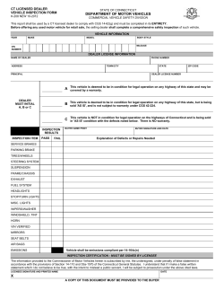


© Copyright 2026