
ssment e Range and Training Land Ass RTLA
April 2006 Range and Training Land Assessment RTLA Technical Reference Manual: Ecological Monitoring On Military Lands DRAFT Preface The first version of this Manual was released in 1999. This revised 2006 version contains an update of RTLA programmatic issues as well as the following new or significantly updated sections: • • • • • • • • • • • • • • • Importance of Ecological Models to Monitoring Programs Potential Monitoring Attributes and Management Applications Related to Range and Training Land Assessment Selecting Indicators of Resource Condition Monitoring Protocols and Program Documentation Data Management Electronic Data Collection Tools Monitoring Noxious and Invasive Plants Monitoring Rare Plants Soil Compaction Assessment Unpaved Roads Condition Assessment and Relationships to Erosion and Sedimentation Bivouac and High-Use Area Monitoring Water Quality Monitoring Fuels and Fire Effects Monitoring Watershed Assessment Aquatic Biomonitoring The ACCESS LCTA User Interface, Structured Query Language, ACCESS LCTA Data Dictionary, and LCTA Field Data Logger Programs sections of the 1999 manual have been published as separate reference documents that can be downloaded from the CEMML web site at http://www.cemml.colostate.edu/. i Executive Summary Range and Training Land Assessment (RTLA) Technical Reference Manual: Ecological Monitoring on Army Lands provides technical information for the monitoring of natural resources, with emphasis on Army lands where training and testing activities occur. The scientific principles and monitoring guidance provided here is fully applicable to other public and private lands. With the exception of wildlife monitoring, the manual is intended to provide Range and Training Land Assessment (RTLA) Coordinators and land managers with a comprehensive, single-source document for the implementation of resource monitoring activities in support of conservation and Integrated Training Area Management (ITAM) programs. The manual focuses on the inventorying and monitoring of vegetation, abiotic components, and ecological processes, and the assessment of changes or trends in resource condition resulting from environmental factors, land management, and military training activities. The monitoring process and program components are described with the aim of promoting sound and defensible monitoring data to support adaptive resource management and sustainable training land use. The manual compiles information from many sources, including federal, state and private land management agencies, the scientific literature, and other unpublished reports. While these agencies may differ in their objectives and approaches to land management, they share a common goal of achieving scientifically sound and effective programs to balance land use and the sustainability of natural resources. Since the mid-1980s, the Army’s Range and Training Land Assessment (formerly Land Condition – Trend Analysis or LCTA) program has provided the foundation for ecological monitoring on Army installations. This manual incorporates much of the knowledge gained from the RTLA program, and expands upon the scientific principles and approaches that have evolved with new programs and objectives. Users of this manual are encouraged to treat it not as a step-by-step guide on how to develop, implement and manage ecological monitoring programs, but rather as a collection of informational sources that can be chosen from and put together to fit a particular geographic location, installation, assemblage of natural communities, populations, species, or other management concern. The manual has been organized to follow a logical progression from how to establish monitoring goals and objectives, to sampling and measurement techniques, followed by data collection and data management considerations. The manual concludes with analysis techniques and procedures to interpret and report monitoring results, with an emphasis on providing feedback for adaptive resource management. ii A brief description of the chapters contained within this manual is presented below: Chapter 1: The Origin and Development of the Range and Training Land Assessment (RTLA) Program This chapter discusses the history and development of RTLA and the changing scope of the program. Chapter 2: Introduction to Resource Monitoring This chapter introduces the reader to resource monitoring by defining monitoring, describing levels of monitoring, possible management applications, management and monitoring objectives, and providing guidelines for developing a successful monitoring program. New sections in this updated version include: Ecological Indicators, and Written Protocols. Chapter 3: Introduction to Sampling This chapter introduces sampling by discussing principles of sampling and sampling design. Chapter 4: Measuring Vegetation Attributes and Other Indicators of Condition This chapter defines common vegetation attributes and explains many methods for measuring these attributes. The original LCTA design and methods is also discussed. New sections in this updated version include: Monitoring Noxious and Invasive Plants, Surveying and Monitoring Rare Plants, Soil Compaction Assessment, Road Condition Assessment and Its Relation to Erosion and Sedimentation, Bivouac and High-Use Area Monitoring, Water Quality Monitoring, Fuels and Fire Effects Monitoring, Watershed Assessment, and Aquatic Biomonitoring. Chapter 5: Data Management This chapter introduces the concept of data management and also provides common data management tasks for RTLA data. Chapter 6: Electronic Data Collection Tools This new chapter describes hardware, software and other considerations for collecting data electronically in the field. Examples of several applications are provided. Chapter 7: Data Analysis and Interpretation This chapter discusses the statistical methods for analyzing monitoring data and for interpreting and extrapolating the results. It also describes some common statistical software and tools. Each chapter contains a list of References and Appendices to support the in-chapter material. iii Questions or comments concerning this document can be sent to: Center for Environmental Management of Military Lands (CEMML) Attn: RTLA Technical Support Dept. 1490 Colorado State University Fort Collins, CO 80523-1490 Or Commander US Army Environmental Center ATTN: SFIM-AEC-EQN RTLA Technical Proponent 5179 Hoadley Road Aberdeen Proving Ground, MD 21010-5401 The suggested citation for this document is: Center for Environmental Management of Military Lands (CEMML). 2006. Range and Training Land Assessment (RTLA) Technical Reference Manual: Ecological Monitoring on Army Lands. Prepared for the U.S. Army Environmental Center (USAEC), Aberdeen MD by the Center for Environmental Management of Military Lands, Colorado State University, Fort Collins CO. This manual is intended to be a “living document” that will be periodically updated based upon comments from field users and managers, advances in technical and scientific knowledge, and human ingenuity. This Manual can be downloaded from the CEMML web site at http://www.cemml.colostate.edu/. iv Acknowledgements RTLA Technical Reference Manual: Ecological Monitoring on Army Lands , was originally a product of many different efforts funded by various agencies and installations of the United States Army in support of the Integrated Training Area Management (ITAM) program. This updated version was prepared under contract to the Army Environmental Center by the Center for Environmental Management of Military Lands (CEMML), Colorado State University, Fort Collins, Colorado. The authors were Chris Bern, Paul Block, Robert Brozka, William Doe, Mark Easter, David Jones, Matt Kunze, Gary Senseman, and William Sprouse. Helpful reviews were provided by Jason Applegate and Jimmy Harmon. The authors acknowledge the contributions made by Alan Anderson (USACERL, Champaign, IL.) and Pat Guertin (USACERL, Champaign, IL). v Table of Contents 1 The Origin and Development of the Range and Training Land Assessment (RTLA) Program _________________________________________________________________1 1.1 Introduction to the RTLA Program _____________________________________________ 1.1.1 Introduction ______________________________________________________________ 1.1.2 Sustainable Range Program (SRP) and Integrated Training Area Management (ITAM)___ 1.1.3 History and Development of RTLA ___________________________________________ 1.1.4 RTLA Process ____________________________________________________________ 2 1 1 1 2 5 1.2 Use of RTLA Data in Reporting and Problem Solving ______________________________ 5 1.3 Conclusions _________________________________________________________________ 6 1.4 References __________________________________________________________________ 7 Introduction to Resource Monitoring___________________________________________8 2.1 Introduction ________________________________________________________________ 2.1.1 What is Monitoring? _______________________________________________________ 2.1.2 Purpose of Monitoring _____________________________________________________ 2.1.3 Steps in Monitoring________________________________________________________ 8 8 8 9 2.2 Importance of Conceptual Ecological Models to Monitoring________________________ 11 2.2.1 Developing Conceptual Models _____________________________________________ 17 2.3 Levels of Monitoring ________________________________________________________ 2.3.1 Qualitative and Semi-quantitative Monitoring (Level 1) __________________________ 2.3.2 Quantitative Monitoring (Level 2) ___________________________________________ 2.3.3 Quantitative Monitoring (Level 3): Demographic, Age or Stage Class Analysis ________ 18 19 19 20 2.4 Management and Monitoring Objectives________________________________________ 2.4.1 Potential Attributes and Management Applications Related to RTLA ________________ 2.4.2 Management Goals and Objectives___________________________________________ 2.4.3 Monitoring Objectives ____________________________________________________ 2.4.4 Paired Management and Monitoring Objectives_________________________________ 20 21 25 27 28 2.5 Determining Benchmarks ____________________________________________________ 31 2.6 Selecting Variables to Measure ________________________________________________ 32 2.6.1 Selecting Indicators of Resource Condition ____________________________________ 32 2.7 Monitoring Intensity and Frequency ___________________________________________ 39 2.8 Written Protocols and Program Documentation__________________________________ 42 2.8.1 Elements of a Monitoring Protocol and Plan ___________________________________ 47 2.9 2.10 Summary: Guidelines for Developing a Successful Monitoring Program _____________ 49 References _______________________________________________________________ 51 vi 3 Introduction to Sampling ___________________________________________________55 3.1 Principles of Sampling _______________________________________________________ 3.1.1 Why Sample? ___________________________________________________________ 3.1.2 Populations and Samples___________________________________________________ 3.1.3 Parameters and Sample Statistics ____________________________________________ 3.1.4 Accuracy and Precision____________________________________________________ 3.1.5 Sampling and Nonsampling Errors ___________________________________________ 3.1.6 Hypothesis Testing Errors and Power Analysis _________________________________ 55 55 55 56 56 58 58 3.2 Sampling Design ____________________________________________________________ 3.2.1 Defining the Population of Interest ___________________________________________ 3.2.2 Selecting the Appropriate Sampling Unit ______________________________________ 3.2.3 Determining the Size and Shape of Sampling Units ______________________________ 3.2.4 Determining Sample Placement (Sampling Design) ______________________________ 3.2.5 Permanent vs. Temporary Plots _____________________________________________ 3.2.6 Sample Size Requirements _________________________________________________ 65 65 66 67 69 79 80 3.3 4 References _________________________________________________________________ 88 Measuring Vegetation Attributes and Other Indicators of Condition ________________93 4.1 Vegetation Attributes ________________________________________________________ 4.1.1 Frequency ______________________________________________________________ 4.1.2 Cover __________________________________________________________________ 4.1.3 Density ________________________________________________________________ 4.1.4 Biomass ________________________________________________________________ 4.1.5 Structure _______________________________________________________________ 4.1.6 Dominance or Composition ________________________________________________ 93 93 94 95 96 98 98 4.2 Methods for Measuring Vegetation Attributes ___________________________________ 99 4.2.1 Frequency Methods______________________________________________________ 105 4.2.2 Cover Methods _________________________________________________________ 108 4.2.3 Density Methods ________________________________________________________ 120 4.2.4 Biomass/Production Methods ______________________________________________ 130 4.2.5 Forest and Tree Measurements _____________________________________________ 133 4.2.6 Photo Monitoring _______________________________________________________ 139 4.3 Specialized Monitoring Attributes and Approaches ______________________________ 4.3.1 Soil Erosion____________________________________________________________ 4.3.2 Monitoring Noxious and Invasive Plants _____________________________________ 4.3.3 Surveying and Monitoring Rare Plants _______________________________________ 4.3.4 Soil Compaction Assessment ______________________________________________ 4.3.5 Land Uses _____________________________________________________________ 4.3.6 Road Condition Assessment and Its Relation to Erosion and Sedimentation __________ 4.3.7 Bivouac and High-Use Area Monitoring _____________________________________ 4.3.8 Water Quality Monitoring_________________________________________________ 4.3.9 Fuels and Fire Effects Monitoring __________________________________________ 145 145 157 172 180 183 184 187 194 203 4.4 Overview of Original LCTA Design and Methods _______________________________ 212 4.4.1 Sampling Design and Plot Allocation ________________________________________ 212 vii 4.4.2 4.4.3 4.4.4 Data Collection Methods__________________________________________________ 213 Findings of the Independent Review Panel____________________________________ 214 Strengths and Weaknesses of the Original LCTA Approach ______________________ 215 4.5 Integrative Approaches _____________________________________________________ 4.5.1 Forest Health Monitoring _________________________________________________ 4.5.2 Rangeland Health _______________________________________________________ 4.5.3 Watershed Assessment ___________________________________________________ 4.5.4 Aquatic Biomonitoring ___________________________________________________ 5 217 217 219 226 230 4.6 Monitoring Ecological Integrity on Public Lands ________________________________ 233 4.7 References ________________________________________________________________ 239 4.8 Appendix Report of 1989 LCTA Review _______________________________________ 260 Data Management ________________________________________________________268 5.1 Data Administration________________________________________________________ 268 5.2 RTLA Data Administration__________________________________________________ 268 5.3 RTLA Data Management ___________________________________________________ 5.3.1 A Priori _______________________________________________________________ 5.3.2 During The Collection Process _____________________________________________ 5.3.3 Database Design ________________________________________________________ 269 269 270 270 5.4 Database Interface Programs for RTLA _______________________________________ 271 5.4.1 LCTA/RTLA Program Manager ____________________________________________ 271 5.4.2 Access RTLA __________________________________________________________ 272 5.5 6 Electronic Data Collection Tools ____________________________________________274 6.1 7 References ________________________________________________________________ 272 Introduction ______________________________________________________________ 274 6.2 Considerations when Choosing Field Computers ________________________________ 6.2.1 What Field Computer Meets Your Needs? ____________________________________ 6.2.2 Major Types of Field Computers ___________________________________________ 6.2.3 Cost __________________________________________________________________ 275 275 275 278 6.3 GPS/GIS Software from Field to Office ________________________________________ 6.3.1 Software Development and Systems Integration _______________________________ 6.3.2 Software Solutions for Increased Productivity _________________________________ 6.3.3 Overview of Software Features_____________________________________________ 6.3.4 RTLA Monitoring Software _______________________________________________ 281 281 281 281 282 6.4 Website Resources for Electronic Data Collection _______________________________ 282 6.5 References ________________________________________________________________ 282 Data Analysis and Interpretation ____________________________________________283 7.1 Introduction and General Guidance___________________________________________ 283 viii 7.2 Analyzing Monitoring Data __________________________________________________ 284 7.2.1 Overview of Statistical Applications_________________________________________ 284 7.2.2 Types of Data __________________________________________________________ 285 7.3 Confidence Intervals _______________________________________________________ 7.3.1 Assumptions ___________________________________________________________ 7.3.2 Calculating Confidence Intervals ___________________________________________ 7.3.3 Comparing a Point Estimate to a Threshold Value ______________________________ 7.3.4 Comparing Two Independent Samples _______________________________________ 7.3.5 Comparing Two Non-independent Samples (permanent plots) ____________________ 285 286 288 288 291 292 7.4 Statistical Tests for Monitoring Data __________________________________________ 7.4.1 Caveats for Statistical Tests _______________________________________________ 7.4.2 Statistical Significance and Confidence Levels ________________________________ 7.4.3 Hypothesis Testing ______________________________________________________ 294 294 295 296 7.5 Choosing a Statistical Procedure _____________________________________________ 7.5.1 Normality Assumptions___________________________________________________ 7.5.2 Frequency/Binomial Tests_________________________________________________ 7.5.3 Parametric Tests ________________________________________________________ 7.5.4 Non-Parametric Tests ____________________________________________________ 7.5.5 Multivariate Analyses ____________________________________________________ 297 297 300 300 315 320 7.6 Interpreting Results ________________________________________________________ 327 7.7 Climate Data Summarization ________________________________________________ 329 7.7.1 Sources of Climatic Data__________________________________________________ 329 7.7.2 Probability of Weekly Precipitation and Climate Diagrams _______________________ 329 7.8 Extrapolating Results_______________________________________________________ 336 7.8.1 Grouping or Pooling Data _________________________________________________ 336 7.9 Linking RTLA and Remote Sensing Data ______________________________________ 7.9.1 Assess Land Condition and Trends__________________________________________ 7.9.2 Classify and Ground Truth Remotely-Sensed Images ___________________________ 7.9.3 Accuracy Assessment of Classified Vegetation and Imagery ______________________ 338 338 338 339 7.10 Additional Analyses ______________________________________________________ 7.10.1 Biodiversity Indices _____________________________________________________ 7.10.2 Similarity Coefficients ___________________________________________________ 7.10.3 Importance Values_______________________________________________________ 343 343 346 351 7.11 Software for Statistical Analysis ____________________________________________ 7.11.1 Spreadsheets and Add-ins _________________________________________________ 7.11.2 Command-Line and Pseudo-Spreadsheets ____________________________________ 7.11.3 Graphics Capabilities ____________________________________________________ 7.11.4 Selecting a Package______________________________________________________ 7.11.5 Stand-Alone Sample Size and Power Analysis Software _________________________ 354 355 356 357 358 358 7.12 Data Analysis using MS Access, MS Excel, Systat, and ArcGIS __________________ 359 7.13 Guidelines for Reporting Monitoring Results _________________________________ 360 ix 7.13.1 Purpose and Types of Reports______________________________________________ 7.13.2 Generic Report Organization ______________________________________________ 7.13.3 Style and Format ________________________________________________________ 7.13.4 Tables ________________________________________________________________ 7.13.5 Graphics ______________________________________________________________ 7.13.6 Brief Format ___________________________________________________________ 7.13.7 Suggested Range and Training Land Assessment (RTLA) Report Outlines for Various Audiences ____________________________________________________________________ 7.13.8 Additional Guidelines ____________________________________________________ 360 361 364 366 367 368 370 374 7.14 References ______________________________________________________________ 374 7.15 Appendix Statistical Reference Tables_______________________________________ 378 x 1 The Origin and Development of the Range and Training Land Assessment (RTLA) Program 1.1 Introduction to the RTLA Program 1.1.1 Introduction Effective management of Army lands requires information regarding initial resource conditions and knowledge of impacts from various types of military training. Environmental degradation associated with military training can have significant short and long-term effects on soil physical properties, vegetation community composition and structure, soil erosion, wildlife and associated habitats, and long-term productivity. There are several reasons for understanding and minimizing the ecological impacts of military training. First, the National Environmental Policy Act of 1969 (NEPA) and U.S. Army Regulation 200-2 (Department of the Army 1980) require that the Army minimize or avoid both short and longterm impacts caused by military training activities. Second, Army training lands are finite while training demands and intensity due to technological changes and base realignments have increased. Therefore, it is in the Army’s interest to sustain soils and vegetation resources on current training lands to meet mission requirements for realistic training and testing. This is especially true in places where the Army trains on and manages land belonging to non-Army federal and state agencies. By documenting and understanding training-related impacts, excessive or irreversible damage and associated land rehabilitation costs can be minimized. Impacts to training lands can result in off-site problems, such as degradation of habitats, water quality, and air quality. Only by establishing effective monitoring programs can the Army optimally manage the resources entrusted to it. The RTLA program inventories and monitors natural resources, and manages and analyzes information regarding resource condition and trends. Data and results are pertinent to management of training lands from the training area to installation scales and provide input to management decisions that promote sustained and multiple uses on military lands. The RTLA program is a long-term effort designed to evaluate relationships between land use and condition, as well as document natural variability over time. 1.1.2 Sustainable Range Program (SRP) and Integrated Training Area Management (ITAM) The Sustainable Range Program is the Army's overall approach to improving the way it designs, manages, and uses its ranges to meet mission training responsibilities. The SRP proponent, Deputy Chief of Staff, G-3, defines two core programs that focus on the doctrinal capability of the Army's ranges and training lands: 1) the Range and Training Land Program (RTLP), and 2) the Integrated Training Area Management (ITAM) program. The SRP core programs are integrated with the facilities management, environmental management, munitions management, and safety program functions that support the doctrinal capability to ensure the availability and accessibility of Army 1 ranges and training lands. Within the Army Test and Evaluation Command (ATEC), SRP is defined by its test ranges and ITAM programs and is similarly integrated with the programs described in the preceding statement. ITAM includes RTLA (formerly known as Land Condition-Trend Analysis or LCTA), Training Requirements Integration (TRI), Land Rehabilitation and Maintenance (LRAM), and Sustainable Range Awareness (SRA). The ITAM Program is the Army's formal strategy for focusing on sustained use of training and testing lands. The intent of the ITAM Program is to systematically provide a uniform training land management capability across the total Army and to help the Army manage its lands to ensure no net loss of training capabilities while supporting current and future training and mission requirements. The effective integration of stewardship principles into training land and conservation management practices ensures that Army lands remain viable to support future training, testing, and other and mission requirements. ITAM integrates elements of operational, environmental, master planning, and other programs that identify and assess land use alternatives. 1.1.3 History and Development of RTLA In April 1984, the Secretary of the Army commissioned an independent panel of scientists to evaluate natural resource management on selected military installations. Among the panel’s findings was that the “single largest constraint to resource management is that natural resource uses are subordinate to military-mission activities.” The panel also noted excessive soil erosion resulting primarily from the use of tracked vehicles. Among the recommendations for improving natural resource management on military lands were the following: 1) Develop and maintain natural resource management plans that are based on current resource inventories and that contain clearly stated resource-use objectives, site-specific prescriptions, and monitoring procedures designed to evaluate action strategies through integrated resource management. 2) Require that new or more adequate natural resource inventories be completed on all military installations and civil works projects by a prescribed time, such as 30 September 1987, with the information to serve as the base for preparing integrated resource management plans. Following the 1984 study, the Land Condition-Trend Analysis (LCTA) program was initiated by the Department of Army as a top-down program emphasizing uniform data collection methodologies to provide regional, MACOM, or national-level assessments of land condition. Development of methodologies for measuring disturbance, vegetation and erosion was undertaken by the U.S. Army Corps of Engineers Construction Engineering Research Lab (CERL), Environmental Division. Implementation of the original methodology (Tazik et al. 1992) (100m permanent transects) took place at dozens of installations across the United States and in Germany in the 1980s and 1990s. Pilot projects were established in 1985 at Fort Carson and Fort Hood to test and validate field methods. Among the first installations to adopt the program in 1986 were Hohenfels Training Area in Germany, and the Piñon Canyon Maneuver Site in southeastern Colorado. On 18 August 1987, a memorandum was issued by the Assistant Secretary of the Army for Installations and Logistics, John W. Shannon, calling for Army-wide implementation of LCTA, and noting that the program could potentially “place the Army in the forefront as knowledgeable and responsible land managers.” The program was implemented on a large scale in 1989, when LCTA was established by CERL at eight Forces Command (FORSCOM), Training and Doctrine Command (TRADOC), and Army Materiel Command (AMC) installations. By 1992, LCTA was in place at 48 Army, National Guard, and 2 Marine Corps installations, funded primarily on a voluntary basis by individual installations using base operations funds. In November 1993, functional proponency for ITAM was transferred to the Training Directorate, Office of the Deputy Chief of Staff for Operations and Plans (ODCSOPS) at HQDA. This action served to align policy and funding for the program with Army training programs, provided official recognition of the program, and instituted it in the Army budgeting and planning process. The emphasis of LCTA at the outset was on data comparability and standardization, permitting aggregation at the Major Command (MACOM) and Department of Army (DA) levels. However, varying installation needs for environmental data, ecoregion differences among installations, and a need for more information on a smaller scale (individual training areas on installations), generated alternative data collection methodologies. Following initial implementation, some installations continued with standard LCTA data collection, sometimes supplementing it with additional monitoring to meet local needs. Other installations largely abandoned the original LCTA methodology in favor of other methods developed by individual RTLA (then LCTA) coordinators. Examination of results, changing program proponency, and shifts in user needs led to a re-evaluation of programmatic and technical aspects of the program in 1996. This effort and resulting recommendations were termed “LCTAII” (USAEC 1996a; 1996b). LCTAII redefined program objectives to support training and range operations as a priority while continuing to provide long-term baseline and trend information for land management needs. Installations were thus given flexibility in using a variety of scientifically acceptable data collection methods that were appropriate to meet local needs. HQDA representatives reviewed the requirements of the Army Training and Testing Area Carrying Capacity (ATTACC) model. Data needed for Universal Soil Loss Equation (USLE) erosion estimates and disturbance information were identified as data required from all installations to support carrying capacity efforts. The ATTACC data requirement was therefore considered a “core” data requirement. Training and Range Operations representatives developed a list of questions that LCTA could help answer. The questions were directly related to carrying capacity/recovery, maneuverability and trafficability, and cover and concealment. Workshop participants agreed that an ecoregion approach for prescribing methods is less relevant than applying methods that best suit individual installation conditions. It was also recognized that data elements required by different users may overlap to varying degrees. With the adoption of ITAM by the training and operations community, the modern RTLA program has evolved to a decentralized, installation-level program that focuses first and foremost on installation needs, and may provide information to Major Commands (MACOMs) and Headquarters, Department of the Army (HQDA) as requested. RTLA objectives are defined by both higher-echelon commands (e.g., Army Headquarters, National Guard Bureau, State Army National Guard Organizations) and individual installations. Army Regulation (AR) 350-19 – The Army Sustainable Range Program (SRP) provides policy guidance for the ITAM Program and RTLA. It incorporates guidance previously contained in AR 350-4, ITAM, and assigns responsibilities and provides policy and guidance for: managing and operating U.S. Army ranges and training lands to support their long-term viability and utility to meet the National defense mission; planning, programming, funding, and executing the core programs comprising the Army’s Sustainable Range Program, the Range and Training Land Program, and the Integrated Training Area Management Program; integrating program functions to support sustainable ranges; assessing range sustainability; and managing the automated and manual systems that support sustainable ranges. In 2004, the LCTA ITAM component was renamed Range and Training Land Assessment (RTLA) to reflect its role in training land management and training support. Relative to the early LCTA 3 Program, the RTLA Program is more focused on training support and training land management, and may be used to support National Environmental Policy Act (NEPA) and other compliance and planning efforts related to Army Transformation, Restationing, and Realignment. Current policies allow installation-level land managers and Range Operations staffs to determine how they can best collect and use resource data to support foundational/long-term and site-specific land management decisions such as training area allocation, training area use and land rehabilitation effectiveness. The current RTLA mission is “to inform the process of military land management to maximize the capability and sustainability of land to meet the Army training and testing mission .” RTLA staff and supporting data and products support Army missions by participating in land-use planning activities and integrating environmental expertise in the initial stages of mission and stationing/restationing planning. This is crucial for ongoing missions, Base Realignment and Closure (BRAC) actions, Army Transformation, and Army Modularity. RTLA monitoring activities may also be included as sources of baseline data and as mitigation in NEPA documents. By being the Range Manager or trainer’s environmental advocate, RTLA Coordinators can provide expertise to enable training areas to be available, in compliance with applicable regulations, and optimally managed for sustained training. Within the context of the RTLA mission statement, programs should: • • • • • • • Provide, in an efficient manner, data, analytical capabilities, and recommendations associated with sustained use of testing and training lands. Provide data to support training land management and land use decisions. Provide data to identify and monitor LRAM sites and evaluate the effectiveness of LRAM efforts. Provide data input to an installation's plans, such as the Integrated Natural Resources Management Plan (INRMP), Integrated Cultural Resources Management Plan (ICRMP), installation master plan, Range and Training Land Plan (RTLP), etc. Provide a means for installation training land managers to measure and monitor natural resources. Provide methods to assess the effects and impacts of training and testing on natural resources. Assess the impacts of natural resources management on training and testing (e.g., prescribed burning, agricultural leasing, livestock grazing, etc.). Changes to the program include a requirement for written, comprehensive protocols, and regular reporting of results to installation staffs and MACOMs. 1.1.3.1 Original RTLA Objectives and Methodology The development of the original LCTA methodology at CERL followed several guiding principles: 1) The protocol would provide objective, scientific data documenting existing conditions of soils, vegetation, and wildlife through inventory and classification of Army lands. 2) The methods would be standardized and applicable across a wide range of ecological conditions, and allow for summaries and comparisons of the data among installations. 3) Data collection would have to be repeatable. 4) The data would be able to evaluate the capability of lands to support sustained military use. The original LCTA methodology describing detailed procedures for monitoring vegetation, soils, small mammals, birds, and reptiles and amphibians is presented in Tazik et al. (1992). In 1989 an independent review panel was convened to review the technical merit of the LCTA program. A report 4 issued by the panel found the methodology technically sound, and recommended some minor changes (Cook 1989). A discussion of the original LCTA methodology is presented in Section 4.4 Overview of Original LCTA Design and Methods. Permanent plots were allocated using a stratified random design, using an unsupervised classification of a satellite image and a map of the soil types. The objective was to represent all major soil and vegetation types on an installation. Budgetary constraints determined the number of plots would be limited by how many two crews could inventory in a season, which was generally around 200. On a typical 100,000-acre installation, this amounted to one plot for every 500 acres, which grew to be a rule of thumb for allocating plots. 1.1.4 RTLA Process RTLA and resource monitoring in general should be viewed as a dynamic process, which is influenced by, and in turn influences, a number of other program areas. Figure 1-1 illustrates RTLA as a process designed to meet specified land management objectives. The major process components include 1) Defining Objectives, 2) Monitoring, 3) Data Management and 4) Reporting. These components are driven and supported by a variety of inputs and activities, and feedback loops. The sequencing of these components is critical to a successful RTLA program. Monitoring in the field cannot proceed without a clear idea of what questions must be answered and what objectives are to be met. Likewise, data management cannot occur without data collected from the field and other sources, and without an idea of how the data should be summarized. 1.2 Use of RTLA Data in Reporting and Problem Solving Since its inception, the emphasis of RTLA has been on data collection. Prior to 2000, on most installations RTLA data was not used extensively for reporting, problem solving, and adaptive management. Few or no reporting requirements partially resulted in a high proportion of the RTLA effort being expended on data collection, rather than on data management, evaluation, analysis, and site-specific applications. As a result, data collected provided limited feedback to support adaptive resource management, mission sustainability, and evaluation of the monitoring design and methods. More recently, numerous installations have begun focusing RTLA efforts, applying RTLA data successfully, and adapting objectives and methods using a systematic approach. Recent requirements regarding protocol development and reporting will promote optimal application of RTLA data. 5 Training and Land Management Needs LCTAII Process: HQDA/MACOM Data Requirements ATTACC OBJECTIVES Evaluation and Improvement Installation RTLA Program Goals and Objectives Technical References and Instructional Manuals ITAM Learning Module for LCTA HQDA/MACOM Policy Guidance and Resourcing Army ITAM Regulation Army ITAM PAM Resource Management Tools: DATA COLLECTION Floristic, other resource surveys Vegetation mapping GIS Database development Monitoring Plans and Protocols Technical Support Services: Quality Assurance Quality Control Methods, Data Management, Data Analysis, Software, Hardware DATA MANAGEMENT Data Analysis Training (formal and informal) Independent Evaluations of Approaches: Vegetation Measurements Rapid Assessments Integrated Approaches Soil Erosion Models REPORTING Data Analysis and Synthesis Management Recommendations Program Evaluation Figure 1-1. RTLA program inputs, process, and support mechanisms. 1.3 Conclusions RTLA was initiated in the mid-1980s by the Department of Army as a top-down program emphasizing uniform data collection methodologies to provide regional, MACOM, or national-level assessments of land condition. With the adoption of ITAM by the Training and Operations community, the RTLA program has evolved to a decentralized, installation-level management of objectives to document the status and trends in natural resources, examine the relationships between disturbance and condition, and support training and testing area land use decisions. Current policies allow installation-level managers (ITAM, range operations, and land management staff) to determine how they can best collect and use resource data to support short and long-term land management decisions such as training area allocation, training area use and land rehabilitation. A successful RTLA program provides scientifically valid baseline and long-term monitoring data. Monitoring is a critical component of the adaptive management cycle, especially in the context of ecosystem management (Leslie et al. 1996), but can only be successful if it is objective-based. Limited resources dictate that qualitative methods be sometimes coupled with quantitative methods to address short- and long-term objectives. Long-term monitoring plots, in addition to non-permanent plots and other sampling sites, reduce the “noise” caused by annual variability and facilitates detection of condition trends over time. This information supports stationing decisions, mission change analysis and ecosystem management activities. It is important to note that RTLA encompasses 6 the collection and analysis of both field-collected and additional data at multiple spatial and temporal scales. RTLA has changed in recent years in response to needs and constraints coming from installations, MACOMs, and HQDA, as well as changes in organizational responsibilities and funding. There is a need for core elements that will remain important over time and flexible regardless of most policy changes. Decision-making at the installation level is essential to ensure that site-specific issues can be addressed effectively. 1.4 References Cook, C.W. 1989. Report of LCTA Review. Unpublished report submitted to USACERL, December 1989. U.S. Army Construction Engineering Research Laboratory, Champaign, IL – Reproduced as appendix in Chapter 4. Department of the Army. 1980. Environmental Quality: Environmental Effects of Army Actions. Army Regulation 200-2, Nov 1980. Department of the Army. 2005. Army Regulation (AR) 350-19 – The Army Sustainable Range Program (SRP). Washington D.C. Leslie, M., G. K. Meffe, J. L. Hardesty, and D. L. Adams. 1996. Conserving Biodiversity on Military Lands: A Handbook for Natural Resources Managers. The Nature Conservancy, Arlington, VA. Tazik, D.J., S.D. Warren, V.E. Diersing, R.B. Shaw, R.J. Brozka, C.F. Bagley, and W.R. Whitworth. 1992. U.S. Army Land Condition-Trend Analysis (LCTA) Plot Inventory Field Methods. USACERL Technical Report N-92/03. Champaign, IL. USAEC (U.S. Army Environmental Center). 1996a. Land Condition Trend Analysis II: Report for Workshop held January 23-25, 1996 in Linthicum, Maryland. USAEC (U.S. Army Environmental Center). 1996b. Land Condition Trend Analysis II: Report for Workshop held August 5-7, 1996 in Linthicum, Maryland. USAEC (U.S. Army Environmental Center). 1998a. Army Regulation 350-4: Integrated Training Area Management. May 8, 1998. USAEC (U.S. Army Environmental Center). 1998b. Department of the Army Pamphlet 350-4: Integrated Training Area Management. Coordinating Draft. August 1998. 7 2 Introduction to Resource Monitoring 2.1 2.1.1 Introduction What is Monitoring? Natural resource inventorying is the process of acquiring information on resources, including the presence, distribution, condition, and abundance of resources such as vegetation, soil, water, natural processes, biotic communities, and natural and human-induced changes in resources (USDI National Park Service 1992). Monitoring is the process of collecting specific information over time to assess conditions and changes or trends in resource status and predict or detect natural or human-induced changes in resource conditions. Indicators of resource condition are often used to evaluate the “condition” or “health” of populations, communities, and landscapes. Three types of monitoring can be described: implementation, effectiveness, and validation monitoring. Implementation monitoring is used to determine if activities and projects are implemented as designed or intended, or at all (Was the activity that was planned actually done?). Effectiveness monitoring determines if activities or projects are effective in meeting management objectives or established guidelines (Did the prescription work or have the desired effect?). Validation monitoring determines whether the data, assumptions, and relationships used in developing a plan are correct (Is there a better way to meet management objectives?). Validation monitoring is often synonymous with research. Most of what is described in this document refers to effectiveness monitoring. Resource monitoring at various landscape scales (i.e. entire installation vs. training area vs. vegetation community, etc.) is a challenging task for land managers and Integrated Training Area Management (ITAM) staff. Monitoring efforts should specifically address management objectives articulated by trainers, land managers, and those presented in integrated natural resource management plans. Management objectives are often placed in categories such as vegetation condition/status (i.e., for different communities), animal habitat, and soil erosion status. Monitoring is valuable also in evaluating different approaches to land rehabilitation and maintenance. The development of missionoriented objectives and projects and a suggested scoping process is described in CEMML (2006). Long-term changes or trends in resources will not be detected reliably if the examination of data is restricted to inconsistent or short-term data. Success of long-term assessments using monitoring data largely depend on creating and using a variety of efficient methods and designs that are both robust and widely useful (Hinds 1984). 2.1.2 Purpose of Monitoring It is important to distinguish between the respective purposes of inventory and monitoring activities. Inventory activities typically precede and contribute significantly to monitoring efforts. Some inventories involve a number of years to collect the necessary information. The primary purposes of resource inventories are to: (1) document the occurrence, location, and current condition of physical 8 habitat and features (site conditions) and major associated biota; (2) identify locally rare or threatened and endangered species, locating fragile or rare ecosystems and potential indicator species; and (3) assess the full range of populations, ecosystem components, processes, and stresses (i.e., both natural and human-caused disturbances), which form the framework for subsequent sampling during the monitoring process (USDI National Park Service 1992). The first cycle of data collection for a monitoring program is sometimes referred to as the “initial inventory” or “inventory year”. The primary purposes of monitoring are to: (1) provide indicators of ecosystem health or status; (2) define limits of normal variation (i.e. natural variability); (3) detect changes in condition, abundance, structure; and (4) identify and understand the effects of management and land-uses. In some cases, monitoring is used to determine compliance with environmental regulations and standards. If properly designed, monitoring activities can provide information linking changes in resource conditions and potential causes. Monitoring provides a rational and objective basis for taking management actions and expands current knowledge of ecosystem properties and processes (Spellerberg 1991). Monitoring should also provide feedback between natural resource conditions and management objectives, an essential component of adaptive resource management. Because inventorying and monitoring help to bridge the gaps between land managers, training and range operations, and research activities, they require both communication and support at a number of administrative levels to be efficient and effective. 2.1.3 Steps in Monitoring Once management objectives have been established, a monitoring program can be designed and reviewed. A conceptual overview of the monitoring process is presented in Figure 2-1. Monitoring efforts must be continually evaluated to ensure that the selected attributes and indicators are sensitive to change and the methods employed are effective. The steps outlined in Figure 2-1 are universally applicable regardless of the scale or duration of the project. Although monitoring is an ongoing process, periodic reporting, ideally following each data collection period, should be performed consistently in order to provide valuable feedback regarding management activities and the success of the monitoring program itself. Analysis involves examining individual components to establish status and interrelationships. Data synthesis subsequently examines the results at multiple scales over time to examine changes and trends. Analysis, synthesis, and reporting of results should be presented in a format that is consistent with the needs of decision makers. 9 Management plan/ objectives Propose general monitoring objectives Select/develop conceptual ecological models Evaluate available data: - historical data - species lists - abundance and distribution data - physical environment - land uses and disturbance - GIS data - other sources Identify specific monitoring objectives and priorities Define personnel and budget constraints Propose sampling design and methods Examine existing data or conduct pilot sampling Revise objectives, design, or methods, as necessary Analyze and evaluate data Does sampling design and methods meet monitoring objectives? no yes Conduct/continue monitoring Analyze and evaluate data Report results and make management recommendations Assess results relative to management objectives Assess results relative to monitoring objectives Figure 2-1. Steps in the development and implementation of a monitoring program (modified from USDI National Park Service (1992) and The Nature Conservancy (1997)). 10 2.2 Importance of Conceptual Ecological Models to Monitoring Conceptual models are a critical tool in the development of a monitoring program. Once the primary ecological communities of interest and other priorities are known, the process of understanding the important elements and processes begins. Conceptual ecological models can be very helpful in summing up what is known about a system and identifying attributes to assess changes in those systems over time. Models should be based on focused management questions that establish the appropriate context for the model. Although they are simplifications of the real world, models can capture relationships that are the basis for predicting changes in our management goals or conservation targets over time. Conceptual ecological models can be created for a variety of conservation targets, including individual or groups of species, vegetation community types or assemblages of community types. The type of model constructed depends on the scientific questions asked, goals and objectives of the project, and characteristics of the conservation targets at the site (Poiani 1999). The models developed relate to and drive the management and monitoring goals and objectives, and support the selection of specific attributes or indicators. In the context of a monitoring program, conceptual ecological models 1: • • • • • • • • • • • Store important information and capture institutional knowledge Provide users with predictive capabilities and scenario-building information Identify priority conservation targets, processes, stressors, and threats (actual or potential) affecting them Help managers and scientists understand ecosystem dynamics, responses to stressors (natural and anthropogenic), and ranges of natural variability Identify links between states/ecosystem components, drivers, stressors, system responses, and monitoring attributes Facilitate selection and justification of monitoring attributes and indicators Facilitate evaluation of monitoring data Provide a framework for interpreting monitoring results in an adaptive management context and prioritizing management actions Document assumptions, knowledge, experience, and unknowns/information gaps Are valuable communication tools for a variety of audiences. Help identify thresholds of condition that may be difficult or impossible to reverse. The term “model” may seem intimidating, but in fact models need not be unnecessarily complex. A variety of terminology and frameworks for conceptual models exists, and may be confusing for the first-time user. The stock, flow, converter, and connector framework grew out of dynamic systems modeling and mechanistic approaches oriented toward quantitative modeling. Models using this framework are often referred to as control or computer simulation models. Examples of control models include population viability and extinction models, forest succession and disturbance models, and fire simulation models. More simplified, management-oriented conceptual ecological models are often used to help direct management and monitoring activities and are described here. They include information about important system components, processes affecting those components, effects of stressors, and often specific attributes that are linked to components and stressors. The models may be represented in tabular form (Table 2-2), simple diagrams or box and wire flowcharts (Figure 2-2 through Figure 1 Adapted from TNC (1994), Peacock (2000), and Gross (2003). 11 2-6), narratives, or a combination of the above. More generalized, non-quantitative models that illustrate system dynamics and response are known as driver-stressor models or state and transition models. For arid and semiarid systems, state-transition (also known as state-transition-threshold) models are often applied (Westoby et al. 1989, Stringham et al. 2001, Bestelmeyer et al. 2003). State-transition models are widely used by the Natural Resources Conservation Service (NRCS), often in the context of grazing management. Under this model, plant communities or ecosystem types are grouped into states that are distinguished from other states by large differences in plant functional groups, ecosystem processes, and the resultant characteristics, including management requirements. Transitions are the shifts between states caused by internal and external factors, and are generally not easily reversed through “natural” processes. Thresholds of condition that delineate irreversible damage may also be included in these models. Box and arrow diagrams are the most commonly-used format for these management-oriented conceptual models. Stressor models and state-transition models are occasionally blended to form conceptual models, and the two terms are sometimes used interchangeably. Strengths and weaknesses of these model types are presented in Table 2-1. Descriptions of transitions in state and transition models often incorporate information about stressors and their effects, lessening the need for a separate narrative to explain the model, as opposed to stressor models, which generally require a separate narrative to describe the processes and changes at work. Regardless of the model type used, scientific references supporting the model relationships should be included to provide rationale and lend credence to the conceptual model. The selection of terminology may be influenced by the framework used by other land managers and scientists in the area. The attributes or indicators identified using the model should be measurable in some way to address the relationship among drivers, stressors, effects, states, etc. Table 2-1. Strengths and weaknesses of state and transition and driver-stressor models. (adapted from Gross 2004). State and transition models • • • • • clear representation of alternative states sometimes address multiple community conditions within a state relatively simple excellent communication with most audiences typically contain no quantitative modeling of flows, processes, states Driver-stressor models • • • • • • provide clear link between agents of change/stressors and important attributes simple and easy to communicate no feedbacks little to no quantitative modeling of flows, processes, states frequently generalized and sometimes incomplete and inaccurate can be too general to directly link to specific attributes/indicators Examples of conceptual ecological models for different ecosystems are presented below. Note that formats vary considerably. In general, diagrammatic models are accompanied by a descriptive narrative to explain some of the relationships or processes illustrated by the graphic. 12 Table 2-2. Examples of ecosystem, drivers, stressors, ecological effects, and related attributes relevant to conceptual ecological models. Ecosystem Drivers Ecological Effects, Responses, or Affected Systems Stressors or Agents of Change Related Attributes Soils and topography • Erosion • Disturbance/use • Compaction • • • • Sediment and nutrient transport Altered soil structure Altered runoff response Reduced productivity • Soil loss estimates • Suspended sediment, Precipitation • Flood • Drought • Erosion • • • • Fire risk Invasion by non-native plants Altered substrates Habitat types/quality • Fire frequency, Community dynamics • • • • • Changes in community structure • Habitat type conversion • Population changes • Presence and abundance Land uses • Disturbance agents, animals, • Native community structure • Establishment and spread of • Multiple, and high • • • • • Fire Establishment Dispersal Predation/mortality Competition vehicles, other activities Altered fire regimes Introduction/dispersal of nonnative species Habitat fragmentation Domestic livestock grazing Resource utilization • Increased or decreased fire • • • • intensity Altered fire return interval Change sin seasonality/timing of fires Prescribed burning Presuppression and suppression activities • • • • invasive species Water quality degradation Changes in wildlife abundance, distribution, survival Loss of species Loss of habitat • Type conversion • Nonnative species invasion potential • Hydrologic response and water quality • Soil seed bank • Vegetation community and habitat types • Changes to species populations and distributions water quality seasonality, severity • Weed abundance • Native habitat quality of species, functional groups, and structural groups. • Extent of habitat types • Population estimates overlap with other driver categories • Fire extent • Fire frequency • Fire intensity and/or severity • Water quality and runoff parameters • Habitat quantity and quality • Nonnative species abundance and spread 13 Figure 2-2. Fire process model for Arkansas River Valley Prairie and Oak Ecosystem coarse community types. From the TNC U.S. Fire Learning Network Workshops held in 2002 and 2003 (http://tncfire.org/documents/USfln/ARRivVal_models_revB.pdf). Figure 2-3. Conceptual diagram of changes in a shrub-steppe community in the absence of fire (Miller et al. 1999, modeled after Archer 1989). This conceptual ecological model was used to identify important elements of a monitoring protocol developed for the Oregon Army National Guard (Jones 2000). 14 T1 I Open stand of sagebrush with productive herbaceous perennial understory. II Dense sagebrush cover. Depleted perennial herbaceous understory with sagebrush seedlings present. T2 T6 T7 T3 IV Dense sagebrush cover. Abundant annuals, few herbaceous perennials and sagebrush seedlings present. T9 T12 T8 T5 T4 III Recently burned. Perennial herbaceous species and sagebrush seedlings. VI Repeated burns. Only annuals with no perennial herbaceous species or sagebrush present. T10 T11 V Recently burned. Dominated by annuals with sagebrush seedlings present. T12 T12 Figure 2-4. State and transition model for sagebrush-grass ecosystem (Laycock 1991, after Westoby et al. 1989). A generic state-and-transition diagram applicable to sagebrush-grass vegetation at Yakima Training Center, Washington and other Columbia Basin installations is presented in Figure 2. The following description of states is modified from Laycock (1991). The boxes represent stable states and the arrows are transitions between states. States I, II, and III represent states that may occur in areas without nonnative annuals. State II represents the degraded state resulting from prolonged heavy grazing, which remains dominated by sagebrush for extended periods. Fire (transition 3), training disturbance, disease, or some other disturbance that kills adult sagebrush will release the perennial understory from competition. State IV represents a situation that might occur in heavily grazed or repeatedly disturbed areas where a well-adapted annual, such as cheatgrass, replaces native perennials in the understory. Fire (transition 8) and repeated fire (transition 10) can then convert this community into a stable state dominated by annuals (state VI). Transition 12 represents human intervention in the form of seeding to adapted perennial species such as crested or Siberian wheatgrass. If successful seeding of native grasses and forbs takes place, transition 12 may lead to State III over time if annuals do not dominate and sagebrush is planted as well. In fact, YTC land managers use criteria similar to these states to determine the need for seeding following fire (i.e., state III versus state VI). Laycock notes that some transitions such as those numbered 2, 7, and 11 are especially difficult to cross. 15 Figure 2-5. Ecological restoration model for upland ecosystems at Fort Benning, Georgia. SERDP, Unpublished report. 16 Figure 2-6. State and transition conceptual model contained in the NRCS ecological site description for a shallow sandy rangeland type in New Mexico. (http://www.nm.nrcs.usda.gov/technical/fotg/section-2/esd/sd2.html). 2.2.1 Developing Conceptual Models The process of developing conceptual models requires the thoughtful integration of knowledge and opinion from a variety or sources, but the models may be relatively simple. Some complex systems may be very difficult to encapsulate within a single conceptual model, necessitating the development of submodels for important components. The key is to develop one or more conceptual models addressing appropriate temporal and spatial scales at the right level of detail, moving from simple models to more comprehensive models. As more is learned about the system, each model can be refined iteratively. The suggested steps listed below build upon Maddox et al. (1999) and Gross (2003). 1. Clearly state the goals of the conceptual model(s). 2. Identify boundaries of the system of interest. 3. Identify and gather key informational resources and data, including published and unpublished reports and scientific papers, subject matter experts, academic and resource management experts, and local professional knowledge and experience. It is possible that applicable models or relevant building blocks have already been developed. 17 4. Articulate key management questions that the model(s) will support. 5. If desired, use informal or formal workshops with local or regional experts, biologists, researchers, and land managers to develop initial frameworks that can be refined over time. 6. Decide on the structure of the model, based on available resources, the intended audience, and planned applications. 7. Identify key model components such as states, natural and anthropogenic stressors, transitions, subsystems, and interactions. The driving processes of the system should be easily discernible. 8. Describe relationships among the states in the system. This may include stressors, ecological factors, and responses, succession, disturbance agents/factors, and other elements 9. Identify and prioritize attributes and indicators. 10. Periodically review, revise, and refine models using in-house resources and external reviewers and incorporate new information as it becomes available. Monitoring may provide feedback that supports or contradicts model assumptions and key components. Some steps will be undertaken sequentially while some will happen simultaneously. 2.3 Levels of Monitoring Approaches to monitoring can be described as “planes” or “levels” of monitoring ranging from the inexpensive and fast to the costly and more time-consuming. Monitoring information and methodologies can be classified as qualitative/semi-quantitative (Level 1), quantitative (Level 2), and demographic (individual/age/stage class analysis) (Level 3) (Menges and Gordon 1996; The Nature Conservancy 1997). Parameters that are measured or estimated include abundance (e.g., number, density, cover, frequency), condition (e.g., vigor, reproductive success, size, biomass, level of damage or disease, etc.), and population or life-history structure (e.g., size class, age-class, number of individuals or that meet specific criteria). The level of monitoring and parameters chosen will depend largely on the management and monitoring objectives supported by the chosen approach and the availability of resources to carry out the monitoring, including time, fiscal resources, and staff resources. A discussion of parameter and indicator selection is presented in Section 2.6. Well-written monitoring goals and objectives indicate which level of monitoring is initially appropriate. Most objectives are best addressed by monitoring resources using several levels of intensity. Monitoring a mixture of parameters within the different monitoring levels is also beneficial. For example, quantitative measures of abundance are often combined with qualitative information such as presence-absence records and ranked data. Efficiency of data collection can often be improved by using diversified approaches. The addition of photographic documentation (Level 1) to almost any other type of monitoring is almost always beneficial. Level 1 and 2 information is most commonly used to assess resource condition. Level 3 studies are often reserved for research activities or in the case of small populations at risk. A generalized summary of goals and analytical approaches to different levels of monitoring is presented in Table 2-3. The discussion of monitoring levels, which emphasizes vegetation monitoring, is based on information provided in Menges and Gordon (1996) and The Nature Conservancy (1997). 18 Table 2-3. Levels of monitoring vegetation, with goals and statistical approach (modified from Menges and Gordon 1996). Level 1. distribution of populations/ communities 2. population/community size or condition 3. demographic monitoring (individuals) 2.3.1 Goals measure trends across populations, hypothesize trends in size measure trends within populations and hypothesize mechanisms/causes anticipate population trends and understand mechanisms Analysis Approaches descriptive trend analysis population variability, age class analysis Qualitative and Semi-quantitative Monitoring (Level 1) Level 1 monitoring is used for both single or multiple locations of species, communities, or other subjects of interest. For example, discreet populations or communities can be mapped through field surveys or aerial photo interpretation. The occurrence, extent, or distribution of populations/communities can be effectively monitoring using this approach. Where multiple occurrences are monitored, the number of locations provides Level 1 information about abundance. This approach allows for examination of changes in populations and locations, changes in area occupied, and large changes in abundance. Using broad ocular estimation categories will only permit coarse indicators of population changes. Increasing the number of estimation categories improves the potential for data analysis but makes repeatability more difficult. Level 1 condition information includes descriptions and presence of attributes or conditions at one or more locations. For example, the presence or absence of different types of erosion, disturbance, hydric soils, seedlings and regeneration, snags of a particular size or type, or stage of vegetation phenology. In addition to presence/absence type data, observers can make estimates of abundance for the condition being exhibited (e.g., 15% crown dieback). Level 1 structure information includes presence/absence of individuals within specified age or height classes, or coarse estimates of abundance within age or size classes. This information gives an indication of population or community structure and recruitment. - Level 1 abundance information includes: presence/absence of a population/individuals at a particular location size of the area encompassed by the population or community estimates of abundance using broad categories or log-scale rankings (1-10, 10-100, 100-1000) photo monitoring Advantages of Level 1 information include relatively low costs and rapid procedures. Communities or populations are assessed in their entirety or by sampling a portion. Disadvantages of Level 1 information include low repeatability and precision, susceptibility to interpretation and observer bias, inability to perform quantitative analysis, and ability to detect only relatively large changes. 2.3.2 Quantitative Monitoring (Level 2) Quantitative monitoring consists of data collection using methods and approaches that have high precision and minimal observer bias and subjectivity. The principal difference between Level 1 and Level 2 monitoring is that actual measurements are made and items counted using Level 2. Examples 19 of methods include density counts, frequency frames, prism cruises, and canopy measurements. Ocular estimates of canopy cover may be treated as either Level 1 or Level 2 information, depending on the method used and the number of cover classes employed. However, increasing the resolution of the estimates (e.g., estimating cover to the nearest 1% or %5) does not necessarily increase the precision of data collection). In fact it may comparisons among observers more problematic. Cover estimation using fairly broad classes is often analyzed using the midpoint of each class as the cover value. The size of the sampling unit (0.5 m X 1.0 m vs. 10 m X 10 m) also influences the use of the data as Level 1 (relatively large quadrats for descriptive purposes) or Level 2 (relatively small quadrats for analytical purposes) data. Population and community abundance is sampled or censused quantitatively using a number of measurements, including the number of individuals, density of individuals, percent cover, and frequency. These measurements can be made on individual species, groups of species, or all species present. Temporary or permanent plots or transects are used with Level 2 information gathering. Condition information consists of relative cover (by species or ecological group) and number or percent exhibiting a particular condition. Population structure measurements typically involve counting the number of individuals in size distribution or height classes (e.g., number of inflorescences, number of insect galls, height). Applying Level 2 methods allows for data analysis, interpretation, and prediction. Smaller changes in condition, structure, and abundance are detectable with Level 2 methods versus Level 1 methods. Another advantage is that the effects of management on sites, areas, and species are more readily evaluated. From a sampling perspective, data collection is repeatable by different individuals over time. Disadvantages include higher requirements of expertise, time, and effort. Also, no information about individual responses or fates is collected. 2.3.3 Quantitative Monitoring (Level 3): Demographic, Age or Stage Class Analysis Level 3 monitoring consists of collecting information for assessing life history or demographic parameters such as survival and mortality and age or size distribution of the population. These studies often measure marked or mapped individuals over time, whereas Level 2 monitoring may make similar measurements on plants but not track individuals over time. By tracking individuals, relationships between recruitment, survivorship, and mortality can be assessed for different age and size classes. Causality can sometimes be determined from these studies. Data collection typically involves measuring abundance attributes and assessing condition. Other qualitative or quantitative information is often collected to help establish relationships between site factors and demographic responses. Strengths of Level 3 monitoring include all those listed for Level 2 monitoring. Additional strengths include increased change detection capability, enhanced knowledge of life histories and response to site conditions, and ability to predict demographic changes over time. Weaknesses include those listed for Level 2 monitoring and high cost and time requirements. 2.4 Management and Monitoring Objectives Monitoring should be objective-based. The success of a monitoring effort is based upon its ability to assess the success or failure of specific management objectives. Objectives must be realistic, specific, 20 measurable, and written clearly. A limited suite of attributes should be chosen for assessing changes in the overall condition of plant communities. It is up to the individual who implements and manages resource monitoring to articulate objectives for his or her program. If good management objectives already exist at an installation, then the remaining task is to define monitoring objectives related to them. Monitoring objectives may also be influenced by original program goals, need for continuity with historic data, methods, and available resources. A good discussion of management and monitoring objectives is presented in Elzinga et al. (1998). 2.4.1 Potential Attributes and Management Applications Related to RTLA When considering the scope and possibilities of a monitoring program, it can be helpful to be aware of potential applications and the data required to support them. Data collection associated with these examples could range from qualitative to quantitative. Discussion of management and monitoring objectives is facilitated through the use of these examples, which are based on projects on DoD installations. These examples are by no means exhaustive, but are meant as a springboard for discussion and program development. The examples of applications and attributes presented here are organized by broad program goals similar 2 to those often used on installations to organize and focus monitoring activities and projects: 1) Document the baseline condition and trends over time in vegetation, soils and hydrologic stability, land cover, aquatic health, ecological processes, and other indices of biotic or abiotic integrity and provide supporting evidence to planning and compliance documents. 2) Document and characterize military land use/training intensity, frequency, types, patterns, and damage over time, evaluate relationships between training and resource condition (e.g., soils, water quality, vegetation, wildlife habitat, etc., including landscape and site-specific impacts), and provide information that may be used to model environmental impacts of training. 3) Characterize the quality and sustainability of training environments. These issues are related to planning events (units) and managing land use (DPT/Range) and may overlap with conservation concerns. 4) Provide information for evaluating the success of ecosystem management (considerable overlap with baseline and trend program area above). 5) Support land rehabilitation and maintenance (LRAM) and help evaluate success of LRAM projects. 6) Provide information, monitoring results, and regular reports to ITAM, Training/Range, Natural Resources, the Installation Commander, and MACOM ITAM staffs for planning, adaptive management, and optimizing RTLA application. Attributes and potential management applications are listed for each program goal. Efforts to support each program goal may have both short and long-term components consisting of a combination of 2 These are not necessarily formal RTLA program goals 21 quantitative and qualitative elements. More specific objectives can be developed and listed for each monitoring attribute (lowest hierarchical level). Document the baseline condition and trends over time in vegetation, soils and hydrologic stability, land cover, aquatic health, ecological processes, and other indices of biotic or abiotic integrity and provide supporting evidence to planning and compliance documents. • • • • Soil erosion and hydrologic stability o Soil loss estimates and soil erosion status – point estimates and spatially distributed modeling o Qualitative evidence of soil loss, movement, flow, litter movement, etc. o Surface soil stability – aggregate stability, biological crusts, litter, plant cover, etc. o Soil compaction o Vegetation cover – total, amount of annual vs. perennial vegetation o Document seasonality of erosion potential Water quality and sedimentation effects o Suspended sediment, turbidity o Aquatic bioassessments – benthics, other indices of stream quality Vegetation/biotic integrity o Amount and distribution of vegetation/community/habitat types o Weed abundance and spread (see more below under ecosystem management) o Plant community composition and structure o Density, cover, frequency, area of occurrence, health/vigor o Diversity and richness indices o Presence and abundance of expected vegetation functional groups Faunal species, indicators and habitat quality o Characterization of status and effects of training on species and habitats of concern and faunal indicators o Songbird/neotropical migrant bird surveys o Small mammal and herptile surveys Document and characterize military land use/training intensity, frequency, types, patterns, and damage over time, evaluate relationships between training and resource condition (e.g., soils, water quality, vegetation, wildlife habitat, etc., including landscape and site-specific impacts), and provide information that may be used to model environmental impacts of training. • • • RFMSS and other military usage data – tabular and spatial data o Monthly and yearly totals by unit type and training area o Seasonal usage and trends in usage over multi-year periods o Training usage intensity of particular facilities/areas of interest Off-road vehicle maneuver patterns and unit footprints o GPS mapping of actual usage to determine use patterns, number of miles traveled, and proportion of on vs. off-road travel. o Analysis of vehicle travel patterns relative to terrain features and land cover/vegetation. Training/testing damage, degradation characterization and mapping o General patterns 22 Site specific/known areas (sometimes repeatedly used areas) Post-maneuver damage assessments o Application of remote sensing imagery and tools to map disturbance and detect changes over time. Complement monitoring with research aimed at building knowledge of links between training effects and resource conditions. Use experimental approaches as well as “control” or “reference” sites/areas for comparison Provide information for watershed assessments and erosion modeling Applications using condition and usage data from other program areas o o • • • • Characterize the quality and sustainability of training environments. These issues are related to planning events (units) and managing land use (DPT/Range) and may overlap with conservation concerns. • • • • • • • Mapping land condition status – criteria may be singular or a combined index of condition. Minimizes harmful effects of training, helps Range personnel distribute training optimally, and provides input to planning tool such as ATTACC o Soil erosion o Weed presence/risk o Habitat degradation/quality for species or communities of concern o Fire risk and effects of wildfire on training and scheduling o Disturbance extent and severity o Other measures of training land carrying capacity Recovery requirements (# of years) for different ecological management units o Applicable to natural and assisted land rehabilitation efforts and modeling training sustainability vis-à-vis soil erosion and vegetation cover Vegetation and land cover maps o Vegetation types o Structural types – physiognomic subclass level, can be species independent o Acreage losses or gains in important training environments over time? Aerial and ground concealment (from detection/observation) o Vertical structure and tactical concealment value Vehicle mobility and terrain analysis o Spacing and size of trees o Soil trafficability o Soil conditions o Slope steepness and topography o Stream crossings o Roads, trails, and accessibility o Condition of roads and trails – driveability Sensitive areas: slow-go and no-go areas o Cultural, environmental, other constraints mapped for troop use. Incorporation of multiple overlays into custom products for planning and training Provide information for evaluating the success of ecosystem management (considerable overlap with baseline and trend program area above). 23 • Fire Regime and Effects o Area burned o Burn severity o Fire frequency/return interval o Vegetation and hydrologic response (pre-post burn or control vs. burned area) o Vegetation dynamics over time o Fuel loads o Relationships between changes in fire regime (frequency, intensity, extent, etc.) and natural resources conditions (vegetation types/quality, soil erosion, etc.) • Forest Management o Tree/forest health indices o Species dominance and forest structure o other • Invasive Plant Management o Mapping species distributions and areas of concentration o Monitoring status and changes in abundance/distribution over time o Evaluating success of management efforts • Habitat Conservation and Enhancement o Total acreage in each vegetation/habitat/land cover type o Habitat fragmentation or loss over time o Monitoring attributes of interest (structure, composition, function, indicator species) • Ground Truthing Data for Remote Sensing Applications o Accuracy assessments of vegetation, land cover, disturbance, or other maps using RTLA data from known locations o Multiple approaches and applications related to this and other program areas Support LRAM and help evaluate success of rehabilitation projects. • • • • • • Identification and assessment of potential LRAM sites Evaluation of species used in seeding mixes Evaluation of effectiveness of structural approaches or controls Evaluation of management success for functional groups such as perennial cover, individual species, composition, and structure (e.g., perennial bunchgrasses, forbs, shrubs, trees, total vegetation cover) Assessment of desirable structural components from habitat or training perspective Maintenance of soil erosion losses below threshold levels Provide information, monitoring results, and regular reports to ITAM, Training/Range, Natural Resources, the Installation Commander, and MACOM ITAM staffs for planning, adaptive management, and optimizing RTLA application. • Comprehensive technical reports 24 • • • • • • 2.4.2 Assessment or determination of “baseline”, “threshold”, or “reference” conditions using RTLA and other data Range and Training reports and briefs Command briefs MACOM ITAM report packs Information sharing and collaboration with other local agencies and organizations Ongoing collaboration with Natural Resources staff to optimize and complement efforts Management Goals and Objectives Management objectives will vary depending on the management mission of a particular organization. For example, management objectives driven by military training (or the training community) may be very different from those established by land management or conservation professionals. Management objectives help to direct resource management by defining desired conditions or trends in resource conditions. Sources of information for setting objectives include existing management plans and environmental (e.g., NEPA) documents, ecological models, reference sites or comparison areas, related or similar species and communities, expert opinion, and historic records and photographs (Elzinga et al. 1998). A complete management objective, which forms the basis for one or more monitoring objectives, should include the following components: what will be measured – direct measurement of species/community or habitat indicator (indirect) location or geographic area of interest – defines the limits to which results will be applied attribute measured, e.g., size, density, cover, frequency, qualitative estimate of abundance, areal extent objective action - maintain, increase, or decrease quantity/status - measurable status or degree of change for attribute – can be quantitative or qualitative time frame - length of time specified for management to prove effective. Objectives can describe either a desired condition or a change relative to current conditions: The first type can be described as target or threshold objectives. This type of objective uses a predetermined threshold to gauge the effectiveness of management. For example: maintain the size of population A at 450 individuals; increase the acreage of open woodland to 6000 ha; maintain the presence of threatened species A and B at Site C. The success of meeting the objective is assessed by comparing the current state of the measured attribute either to the desired state or an undesired state. Presence of the undesired state should serve as an indication that management should be altered. The second type can be described as change or trend management objectives. This type of objective specifies a change relative to the existing situation. For example: increase perennial grass cover by 40%; decrease severe off-road disturbance by 20%; decrease frequency of weed species Y by 50%. Trend objectives are useful when little information is available to describe a desired future condition, or where the current status is less important than trends over time. Change detection objectives are 25 often appropriate when a significant change in management occurs and change is anticipated. If preliminary sampling provides information about the population status, then a change objective may be rewritten as a threshold objective. Some of the major management concerns related to resource condition and military land uses include: • • • • • Off-road vehicle and other training impacts to vegetation and soils Spread of noxious weeds or species which outcompete desirable vegetation Changes in structural attributes of plant communities – loss of concealment resources, wildlife habitat Impacts of altered fire intensities/frequencies and other natural processes Soil erosion, sedimentation, and water quality impacts In light of these management concerns, the following are examples of general management goals related to vegetation and soils: 1. Sustain and maintain healthy and diverse ecosystems. 2. Maintain soil stability and susceptibility to erosion at acceptable levels. 3. Maintain realistic and sustainable training environments for desired training loads. 4. Revegetate selected disturbed areas to pre-disturbance conditions. 5. Minimize the establishment and spread of undesirable non-native plants. These general management goals should be refined so that corresponding monitoring objectives can be developed to address specific needs. If the success or failure of the management objective cannot be gauged, then there is no way of knowing if management activities are effective, or if management goals are met. The following are examples of specific management objectives: ♦ Maintain the current (2005) spatial distribution and abundance, i.e., acreage, of each major plant community from 2005-2010 (target objective). ♦ Within each community type, maintain 2003-2005 native grass, forb, shrub, and tree cover from 2005-2010 (target objective). ♦ Within each community type, maintain 2003-2005 native grass, forb, shrub, and tree diversity from 2005-2010 (target objective). ♦ Increase the forb diversity of woodland communities by 25% between 2005 and 2015 (change objective). ♦ In existing shrub communities, maintain current (2003-2005) densities for each shrub species from 2005-2010 (target objective). 26 ♦ Allow a decrease in the ranked abundance of Chlorogalum purpureum var. purpureum (Purple Amole) in each of the 5 permanent macroplots at the Jones Mountain Site (Fort Hunter Liggett, CA) of no more than 1 rank class between 2005 and 2007. ♦ Within each training area, maintain current (2003-2005) soil erosion rates from 2005-2010 (target objective). ♦ Within each community type, maintain current (2003-2005) levels of bare ground from 20052010 (target objective). ♦ Maintain the current (2004) areal extent of forest, woodland, and grassland communities from 2004-2009 (target objective). ♦ In forested areas used for bivouac, maintain an overstory tree density of at least 40 trees/ha from 2003-2008 (target objective). ♦ For revegetation sites, increase cover of desirable plant species to within 50% of undisturbed plant cover after three years of recovery (change objective). ♦ For revegetation sites, provide at least 20% perennial grass cover, 10% shrub cover, and 5% perennial forb cover after 2 years of recovery (target objective). ♦ For burn sites, increase total plant canopy cover to 25% after 1 year (target objective). ♦ Maintain the current distribution and abundance of weed species X on Fort USA from 2003 to 2008 – this could be treated as quantitative or qualitative, depending on the approach that is most feasible (target objective). ♦ Decrease the number of hectares on Fort USA infested with species Y (species is common to abundant) to 400 ha (target objective). ♦ For sites treated for weed infestations, decrease the density of target weed species by at least 50% one year after treatment (change objective). ♦ Maintain the number of km of road shoulders with a knapweed (all species) ranked abundance of 5 or more (target objective). 2.4.3 Monitoring Objectives Complete management objectives form the basis for monitoring or sampling objectives. In addition to the “what”, “where”, and “when”, a monitoring objective should specify information such as the target level of precision (acceptable error), power, confidence level (false change error rate), and the magnitude of change we want to detect. Without specified targets for these parameters, estimates of population parameters might have excessively large confidence intervals or low power (e.g., only a 20% chance of detecting the magnitude of change that was desired). The necessary components of monitoring objectives differ for target management objectives and change management objectives. The sampling objective for target objectives is to estimate a parameter in the population, estimate a proportion, or to estimate total population size. This estimate is then compared to the threshold value 27 specified. To accomplish this, it is necessary to specify the confidence level (i.e., how confident do you want to be that your confidence interval will include the true value?), and the confidence interval width (i.e., how close to the estimated mean do you want to be?). Example: Management objective: Decrease the density of Juniperus trees less than 10 cm in diameter in abandoned agricultural fields to 15 trees/acre between 2005 and 2010. Monitoring objective: Estimate the density of Juniperus trees less than 10 cm in diameter. We want to be 90% confident that mean density is within 10% of the estimated true value. The sampling objective for change objectives is to determine if there has been a change in a population parameter for two or more time periods. These objectives must include the desired power (missed change or Type II error), the acceptable false change errors rate (Type I error), and the desired minimum detectable change (MDC) (the smallest change you are hoping to detect). Example: Management objective: Increase the density of flowering individuals of Tauschia hooveri (Hoover’s desert parsley) at the Yakima Ridge site by 25% between 2005 and 2015. Monitoring objective: We want to be 90% confident of detecting a 25% increase in mean density with a false change error rate of 0.10. This objective specifies a power of 90%, a false change error rate of 10%, and an MDC of 20%. If the sampling interval is not specified in the management objective, it should be specified in the monitoring objective (i.e., seasonally, annually, every 2 years, 5 years, etc.). The sampling interval can be less than the timeframe specified in the management objective. For example, if a given change is desired over a 6 year period, monitoring every 2 or 3 years may be appropriate to see if there has been progress toward the objective. When monitoring does not involve sampling, the management objective should provide enough information to evaluate its success or failure. This is the case where qualitative assessments are done for areas or where a complete census is performed. Management objectives of this type therefore do not need to provide additional components beyond what, where, and when. 2.4.4 Paired Management and Monitoring Objectives 2.4.4.1 Examples of Training-oriented Objectives Example 1: Management Objective (desired status or condition - management threshold) “Mean soil erosion status (estimated soil loss/published soil loss tolerance) shall be maintained at levels of less than 100% for all major landcover types on the installation.” Monitoring Objective 28 “We want to make annual estimates of erosion losses for all the major landcover types. We want to be 90% confident that the estimate is within 10% of the true value.” Example 2: Management Objective (desired condition) “[Given that sagebrush is sensitive to off-road maneuvers and fire] we want to maintain mean big sagebrush cover of at least 25% in existing shrub stands across the installation.” Monitoring Objective “We want to obtain an estimate of the average canopy cover of big sagebrush in existing shrub stands every two years. We want to be 90% confident that the estimate is within 20% of the true value.” 2.4.4.2 Examples of Land Management-oriented Objectives Example 1: Management Objective (desired trend) “We want to see a 50% decrease in yellow star thistle in areas sprayed with herbicides on Fort Hunter Liggett during the next three years.” Monitoring Objective “We want to be 90% sure of detecting a 50% change in the density of yellow star thistle on herbicided areas and untreated areas annually for the next 3 years. We are willing to accept a 10% chance that we conclude a change took place when in fact there was no change.” Example 2: Management Objective (desired trend) “Through the application of management activities, we want to see a 30% increase in the cover of native warm-season grasses at the McLaughlin Cemetery Glade (Fort Leonard Wood, MO) between 2004 and 2007.” Monitoring Objective “We want to be 90% sure of detecting a 30% change in the aerial cover of native warm-season grasses at the McLaughlin Cemetery Glade 3 years after the initiation of restoration activities. Monitoring will be done annually. We are willing to accept a 10% chance that we conclude a change took place when in fact there was no change.” Example 3: Management Objective (desired status) “We want to maintain the current flowering population of Tauschia hooveri (Hoover’s desert parsley) at the Yakima Ridge site (Yakima Training Center, WA) over the next ten years.” 29 Monitoring Objective “We want to obtain annual estimates of the population of Hoover’s desert parsley at the Yakima Ridge site from 2003-2013. We want to be 90% confident that the estimates are within 20% of the estimated true mean.” 2.4.4.3 Additional Examples of Paired Management and Monitoring Objectives 1. In grassland communities, decrease the frequency of Bromus tectorum (cheatgrass) by 30% from 2005-2008. We want to be 80% certain of detecting a 30% decrease in frequency with a false change error rate of 0.20. 2. Maintain native grass and forb species diversity at 2003-2004 levels. Obtain estimates of grass and forb diversity at 2 year intervals with 90% confidence intervals no wider than ± 10% of the estimated diversity. 3. Maintain the areal extent and distribution of minimally, moderately, severely, and completely, disturbed (e.g., off-road maneuver and assembly) areas at 2005 levels. Estimate annually the extent (i.e., number of square meters, ha) of disturbed lands in each disturbance category and map areas using GPS – the objective has all the information for evaluating results. 4. In areas subject to extensive off-road maneuvers, allow a decrease in the cover of native plants of no more than 30% relative to undisturbed conditions between 2005 and 2008 (compared to undisturbed areas). Be 80% confident of detecting a 30% relative decrease in native plant cover with a false-change error of 20% (20% chance of concluding that a change took place when in fact there was no change). 5. In forested areas used for bivouac, maintain an overstory tree density of at least 40 trees/ha from 2003-2006. We want to be 95% certain that the estimates are within 15% of the estimated true density. 6. In existing shrub communities, maintain current (2003-2005) densities for each shrub species from 2005-2010. We want to be 95% confident that annual density estimates are within 10% of the estimated mean density. 7. Increase the forb diversity of woodland communities by 25% between 2005 and 2010. We want to be 90% sure of detecting a 25% relative increase in forb diversity. We are willing to accept a 10% chance of a false-change error. 30 8. Increase the Jones Mountain (Fort Hunter Liggett, CA) population of Chlorogalum purpureum var. purpureum (purple amole) to 500 individuals by the year 2009. We want to be 95% confident that the population estimate is within ± 10% of the estimated true value. This objective applies where sampling is used. If all of the individuals in the population are counted (census), then the monitoring objective is already specified within the management objective (are there at least 500 individuals by 2009 – yes or no?). 9. Decrease the ranked abundance of Lythrum salicaria (purple loosestrife) in each of the four permanent macroplots at the Ives Road Fen site by 2 rank classes between 2004 and 2006. Estimate the ranked abundance of purple loosestrife in each macroplot – the objective has all the information for evaluating results. Estimates could be made annually or in 2004 and 2006. 10. Do not allow erosion status estimates (estimated loss/allowable loss) for each training area to exceed 100% in any given year from 2004-2014. Estimate erosion status annually for each training area. We want to be 90% confident that the estimate is within ± 20% of the estimated true value. Additional examples of management and monitoring objectives for RTLA programs are presented in CEMML (2006). 2.5 Determining Benchmarks Benchmarks or management thresholds provide goals for resource management, which in turn help to guide monitoring efforts. In the context of quantitative monitoring, benchmark conditions must be defined for the attributes of interest, which are measured during sampling. Benchmarks are often a set of well-defined conditions as opposed to a qualitative ranking such as “poor”, “fair”, or “good”. However, qualitative benchmarks may be used where monitoring resources are limited or where qualitative management objectives are specified. In some cases, monitoring data are compared to initial conditions to gauge improvement or degradation, emphasizing trend over the attainment of specific conditions. In fact, both approaches can be employed simultaneously without expending additional effort or cost, the only difference being that attention must be given to defining benchmarks. Commonly used benchmarks include current conditions or those preceding changes in management, pristine or near-pristine sites (reference areas), historic or presettlement conditions, desired plant community, and projections from biotic and abiotic information – “climax” or potential vegetation. Some of these benchmarks represent hypothetical ecological standards. Desired plant community (DPC) is a concept that has been adopted by some land managers as a practical benchmark for vegetation management. This concept has also been described as desired future condition (DFC). Wagner (1989) describes the DPC concept: “The DPC is … an expression of the site specific vegetation management objectives instead of the more common, subjective way of stating objectives such as changing vegetation condition from poor to fair or from fair to good. The description of the characteristics of the DPC (species composition, production, 31 cover structure, etc.) is based on those of a real, documented community occurring on the same or like site in another area. Therefore, vegetation management objectives expressed as a DPC, besides being more specific and measurable, are ultimately more realistic… The DPC is consistent with the site’s documented capability to produce the required vegetation attributes through management, land treatment, or a combination of the two. The DPC is a management determination which may correspond to the existing plant community, the potential plant community, or some intermediate community.” Where resource conditions generally meet management objectives and changes in management are minimal, current conditions may be chosen as a benchmark for quantitative or qualitative monitoring. The emphasis might therefore be on maintenance of conditions versus improvement over time. 2.6 Selecting Variables to Measure Assessing the condition of any ecosystem, be it forest, woodland, grassland, shrubland, or arid ecosystem, is highly complex, requiring the examination of a number of factors which characterize or contribute to the degradation or improvement of various ecological units. Changes or trends in ecological resources can be detected in the short and long-term by monitoring resources either directly or indirectly through indicators. The selection of variables to measure is largely determined by program objectives and corresponding data requirements. Required data elements are simply whatever has been requested by the responsible party or agency. Population-level monitoring can be straightforward if the species lends itself to being measured directly. Community and landscape-level monitoring can present the most difficulties in the selection of attributes. For this reason, indicators are used most often at the latter scales. Whatever the variables chosen, they should be robust yet specific enough to respond to anticipated or unknown stresses and changing conditions. Compliance-type monitoring generally specifies the attributes to be monitored. Standardization of data collection requirements across organizational units (e.g., MACOM requirements for installations, range condition ratings by BLM districts) simplifies the process of determining what to measure by specifying data needs. For example, the Army Training and Testing Area Carrying Capacity (ATTACC) model, currently being developed by Combat Training Support Center (CTSC) for the Office of the Deputy Chief of Staff for Operations and Plans (ODCSOPS) requires soil loss estimates by training area in order to estimate the capacity of lands to support training. Soil erosion status is used to help determine “land condition”. Training load and land rehabilitation costs are also required by the ATTACC model. The ATTACC requirements and calculation of carrying capacity estimates are presented in the ATTACC Program Handbook (CTSC 1998). 2.6.1 Selecting Indicators of Resource Condition Assessment of condition requires that judgments are made regarding the ecological significance of the indicator variables measured. Multiple indicators are preferable to single indicators because of the decreased chance of false positive and false-negative signals. Qualitative measurements of indicators may be appropriate and cost effective where large impacts are anticipated and readily apparent. 32 The importance of indicator selection cannot be over emphasized, since any long-term monitoring project will only be as effective as the indicators chosen (Cairns et al. 1993). Once management goals have been specified, a framework must be developed for selecting indicators and utilizing the data that is collected. The number of potential indicators is relatively high, and the selection of several “good” indicators is not an easy task. However, economic and ecological considerations help to limit the number of indicators that can be measured to a fraction of those available. In some cases, indicators may need to be developed if they are specific to an installation need (e.g., rutting, types of training damage, etc.). The following list of indicator characteristics was developed for applications to environmental and water quality, but are widely applicable to terrestrial ecosystems as well (Cairns et al. 1993). The ideal indicators are: 1. 2. 3. 4. 5. 6. 7. 8. 9. 10. 11. 12. 13. 14. 15. Biologically relevant, i.e., important in maintaining a balanced community; Sensitive to stressors without an all or none response or extreme natural variability; Broadly applicable to many stressors and sites; Diagnostic of the particular stressor causing the problem; Measurable, i.e., capable of being defined and measured using a standard procedure with documented performance and low measurement error; Interpretable, i.e., capable of distinguishing acceptable from unacceptable conditions in a scientifically and legally defensible way; Cost-effective, i.e., inexpensive to measure, providing the maximum amount of information per unit effort; Integrative, i.e., summarizing information from other, unmeasured indicators or variables; Historical data are available to define “natural” variability, trends, and possibly acceptable and unacceptable conditions; Anticipatory, i.e., capable of providing an indication of degradation before serious harm has occurred: early warning; Nondestructive of the ecosystem; Potential for continuity in measurement over time; Of an appropriate scale to the management problem being addressed; Not redundant with other measured indicators; Timely, i.e., providing information quickly enough to initiate effective management action before unacceptable damage has occurred. Numerous research and monitoring projects have been undertaken to identify indicators that are ecosystem appropriate and meet the criteria described above. In some cases it is appropriate to measure the attribute of interest directly (e.g., is the acreage of Purple Loosestrife expanding?) while in other cases the use of indicators is appropriate (e.g., are we maintaining the quality of native plant communities in area x?). Some indicators are discrete, measurable attributes whereas other may be represented by one or more additional attributes or may require further determination of specific metrics. The selection of appropriate indicators for arid and semiarid environments has received much attention in recent years. Some work has focused on selecting site-specific indicators and attributes, whereas other work has investigated indicators that are broadly applicable across a range of environments. 33 The Rangeland Health Program was initiated following a report released by the Committee on Rangeland Classification (1994). Development of Rangeland Health concepts, methods, and applications has been spearheaded by USDI, USDA and university researchers. The program aims to evaluate an ecological site's potential to conserve soil resources by assessing a series of indicators for ecosystem processes and site stability. Seventeen indicators are evaluated to assess three ecosystem attributes (soil and site stability, hydrologic function, and biotic integrity) for a given location. Indicators include rills, water flow patterns, pedestals and terracettes, bare ground, gullies, wind scour and depositional areas, litter movement, soil resistance to erosion, soil surface loss or degradation, plant composition relative to infiltration, soil compaction, plant functional/structural groups, plant mortality, litter amount, annual production, invasive plants, and reproductive capability. The assessment techniques employed by the Rangeland Health methodology (Pellant et al. 2005) is qualitative in nature and is not intended to be used as a monitoring tool. However, the indicators have been shown to meet important selection criteria outlined above. A number of methods could be applied to assess the condition of the indicators listed. The Rangeland Health framework and approaches are further described in Section 4.5.2 Rangeland Health. In Arches National Park, Utah, Belnap (1998) used a systematic approach to select indicators of natural resource condition. The basic approach involved sampling a number of vegetation and soil variables in impacted and unimpacted areas. Variables that differed significantly between compared sites were chosen as potential indicator variables. Potential indicators were subsequently evaluated using site-specific criteria. The required selection criteria for indicators included low impacts of measurement, repeatability of measurements, correlation with land-use (i.e., visitor/recreation) disturbances, and ecological relevancy. Those indicators that met the required criteria were then evaluated for additional desirable characteristics, including: (1) quick response to land-use disturbance and management actions, (2) minimal spatial, temporal, and climatic variability, (3) ease of sampling, (4) large sampling window, (5) cost effectiveness, (6) short training time, (7) baseline data available, and (8) response over a range of conditions (impacts are evident even for minimal disturbance). The remaining indicators were then examined for ecological relevancy. A final set of indicators was then chosen and field tested. This approach should prove applicable in situations where indicators are required to measure both land-use impacts and response to management actions. Several years may be required to survey habitats, develop a list of potential indicators, determine ecological relevance, and field-test chosen indicators (Belnap 1998). Examples of vegetation and soil indicators selected for areas in Utah (Belnap 1998) and New Mexico (Whitford et al. 1998) include: - bare patch index cover of long-lived grasses weighted soil surface stability index cover of plant species toxic to livestock cover of exotic species cover of increaser species number of social recreational trails soil crust index soil compaction soil aggregate stability vascular plant community composition soil surface protection index soil biological characteristics 34 Some of these indices are measured directly some are derived from several measurements or variables. Additional work on rangeland indicator selection was published in 2003 by the Sustainable Rangelands Roundtable (SRR) 3. The SRR is a collaborative partnership process jointly funded by the USDA Forest Service, Bureau of Land Management, the U.S. Geological Survey, and Colorado State University. The SRR mission is to promote ecological, economic, and social sustainability of rangelands through the development and widespread use of criteria and indicators for rangeland assessments, and by providing a forum for dialogue on rangeland sustainability. The SRR met 11 times and employed a collaborative Delphi Process 4 to produce a report of criteria and indicators for assessing sustainable rangeland management in the United States. During the course of these meetings, more than 100 scientists representing about 50 agencies, universities, professional societies, NGOs, and private businesses participated in the process. A framework of five criteria and 64 indicators was developed to promote standardized, periodic rangeland inventory and monitoring at multiple scales. The first three criteria relate to resource condition, whereas the last two pertain to social, economic, and legal issues. Indicators for the first three criteria are presented below. Criterion 1. Conservation and Maintenance of Soil and Water Resources of Rangelands Soil-based Indicators 1. Area and percent of rangeland soils with significantly diminished organic matter and/or high carbon:nitrogen (C:N) ratio. 2. Area and extent of rangelands with changes in soil aggregate stability. 3. Assessment of microbial activity in rangeland soils. 4. Area and percent of rangeland with significant change in extent of bare ground. 5. Area and percent of rangeland with accelerated soil erosion by water or wind. Water-based Indicators 6. Percent of water bodies in rangeland areas with significant changes in natural biotic assemblage composition. 7. Percent of surface water on rangeland areas with significant deterioration of their chemical, physical, and biological properties from acceptable levels. 8. Changes in ground water systems. 9. Changes in the frequency and duration of surface no-flow periods in rangeland streams. 10. Percent of stream length in rangeland catchments in which stream channel geometry significantly deviates from the natural channel geometry. Criterion 2: Conservation and Maintenance of Plant and Animal Resources on Rangelands 11. Extent of land area in rangeland. 12. Rangeland area by plant community. 13. Number and extent of wetlands. 14. Fragmentation of rangeland and rangeland plant communities. 15. Density of roads and human structures. 3 http://sustainablerangelands.cnr.colostate.edu/ Delphi is an iterative process whereby experts answer a set of questions; individual responses are tabulated and returned to the participants, along with summary analyses and comments. Individuals are then afforded an opportunity to revise their original answers in response to the group feedback. The process continues until a pre-determined level of consensus is achieved. 4 35 16. Integrity in natural fire regimes on rangeland. 17. Extent and condition of riparian systems. 18. Area of infestation and presence/absence of invasive and other nonnative plant species of concern. 19. Number and distribution of species and communities of concern. 20. Population status and geographic range of rangeland-dependent species. Criterion 3: Maintenance of Productive Capacity on Rangelands 21. Rangeland aboveground biomass. 22. Rangeland annual productivity. 23. Percent of available rangeland grazed by livestock. 24. Number of domestic livestock on rangeland. 25. Presence and density of wildlife functional groups on rangeland. 26. Annual removal of native hay and nonforage plant materials, landscaping materials, edible and medicinal plants, and wood products. The National Park Service has developed a program called Vital Signs Monitoring 5 (VSM). VSM organizes approximately 270 park units into 32 monitoring networks to conduct long-term monitoring for key indicators of change, or “vital signs.” Vital signs are measurable, early warning signals that indicate changes that could impair the long-term health of natural systems. Individual networks link parks that share similar geographic and natural resource characteristics. Each network is tasked with designing a single, integrated program to monitor both physical and biological resources, such as air quality, water quality, soils, exotic species, and threatened and endangered species. The list of environmental vital signs selected for monitoring the health of these resources is expected to vary among networks, reflecting the needs and natural resources of the parks. Partnership opportunities, ecological indicators and methodologies involved differ from one network to another, as appropriate. Vital Signs employs a framework consisting of three levels (Level 1, Level 2, and Level 3 categories) to which each network vital sign is assigned. For example, the vital sign 'Biological Soil Crusts' is assigned to Level 1 = Geology and Soils, Level 2 = Soil Quality, and Level 3 = Soil Structure and Dynamics. The vital sign 'Landbirds' is assigned to Level 1 = Biological Integrity, Level 2 = Focal Species or Communities, and Level 3 = Birds. The three most common vital signs identified by the initial 12 networks are exotic plant species occurrence, changes in land cover type (e.g., agricultural to suburban), and vegetation community composition and structure. The USDA Forest Service, Forest Health Monitoring (FHM) is a national program designed to determine the status, changes, and trends in indicators of forest condition on an annual basis. Forest indicators used by this program include crown condition, lichen communities, ozone injury, downed woody debris, tree damage, vegetation diversity and structure, tree mortality, and soil condition. FHM is further described in Section 4.5.1 Forest Health Monitoring. The Forest Inventory and Analysis (FIA) Program is another USDA Forest Service program (http://fia.fs.fed.us/). FIA reports on status and trends in forest area and location; in the species, size, and health of trees; in total tree growth, mortality, and removals by harvest; in wood production and utilization rates by various products; and in forest land ownership. FIA recently assumed responsibility for all former Forest Health Monitoring Program (FHM) plot work on a national level. In addition to traditional forestry and forest mensuration measurements, FIA also collects information on indicators that were developed and initially measured by the FHM Program in the 1990s (see 5 Description of the Vital Signs Program from http://www.nature.nps.gov/protectingrestoring/IM/vitalsignsnetworks.htm 36 Section 4.5.1 Forest Health Monitoring). In 1999, responsibility for these data elements was transferred to FIA and now are a subset of the FIA sample grid (one forest health plot for every 16 standard FIA plots). On the forest health plots, core FIA measurements (for example, height, diameter, species) are made, as well as the forest health measurements. Harper et al. (1996) have outlined several indicators of community quality specific to southern pine woodlands, including: a) wiregrass dominance as an indicator of little fire suppression or soil disturbance, b) old growth pine as an indicator of high quality sites for many TES, c) other indicator species, and d) structural and compositional aspects. Land-use impact issues on military installation in the Southeast include: fragmentation and land-use conversion, fire and fire suppression, alteration of hydrology, groundcover disturbances, erosion and sedimentation, soil compaction, exotic and pest species, and unnatural fertilization. Indicators must accordingly be applicable to these and other management issues. Several studies of national-level indicators have been undertaken in recent years. The National Research Council (2000) recommended a number of ecological indicators at the national level. Recommended indicators of ecosystem extent and status include land cover and land use. Changing proportions of various categories are indicative of changes in these indicators. Recommended indicators of ecological capital include total species diversity, native species diversity, soil organic matter, and nutrient runoff. Recommended indicators of ecosystem functioning include production capacity (chlorophyll density), net primary production, carbon storage, stream oxygen, and trophic status of lakes. These indicators are broad, but are widely applicable and have been refined for specific needs at regional and local scales. Additional research involving selection and evaluation of ecological indicators has been published by The Heinz Center (2003). The State of the Nation's Ecosystems provides up-to-date information regarding the status of data for evaluating the condition of numerous national indicators (http://www.heinzctr.org/ecosystems/report.html). Examples of indicators for forest, grassland, and shrubland ecosystems are presented in Table 2-4. 37 Table 2-4. System dimension and biological component indicators for forests, grasslands, and shrublands (The Heinz Center 2003). Forests CATEGORY SYSTEM DIMENSIONS BIOLOGICAL COMPONENTS INDICATOR(S) DESCRIPTION Forest Types How is the area occupied by major forest types changing? Forest Pattern and Fragmentation How fragmented are U.S. forests? At-Risk Native Species What are the percentages of forest-dwelling species that are at different levels of risk of extinction? Area Covered by Non-native Plants What percentage of the plant cover in forests is not native to the region? Forest Age How much of the nation's forests is young, middle-aged, or old? Forest Disturbance: Fire, Insects, and Disease How many acres are affected each year by fires, insects, disease, windstorms, and ice? Fire Frequency Are forest fires burning much more or less frequently than in presettlement times? Forest Community Types with Significantly Reduced Area How much area is occupied by forest types that have significantly declined in area since presettlement times? Are these forest types increasing or decreasing in area at present? Grasslands and Shrublands SYSTEM DIMENSIONS BIOLOGICAL COMPONENTS Area of Grasslands and Shrublands How much land is covered by grasslands and shrublands? Land Use How are grasslands and shrublands used? How many acres are used for livestock grazing; oil, gas, and mineral development; rural residences; intensive recreation; "protected areas"; and the Conservation Reserve Program? Area and Size of Grassland and Shrubland Patches What fraction of grasslands and shrublands is found in patches of various sizes? At-Risk Native Species How many grassland and shrubland native species are at different levels of risk of extinction? Non-native Plant Cover What percentage of grassland and shrubland plant cover is not native to the region? Population Trends in Invasive and Noninvasive Birds Are invasive bird populations increasing more than other bird populations? Fire Frequency Index Are grassland and shrubland fires occurring more or less frequently than in presettlement times? 38 2.7 Monitoring Intensity and Frequency Determining the intensity (level of monitoring approach and effort) of sampling is influenced by three principal factors: 1) program objectives, 2) funding and other resources, and 3) actual or perceived threats or level of risk. Intensity and frequency of data collection is influenced also by program or management objectives, including documents such as Integrated Natural Resource Management Plans (INRMPs); or ongoing mission, restationing, or land acquisition environmental documents including Environmental Impact Statements (EISs) and Environmental Assessments (EAs). In addition to supporting training activities and conservation goals, monitoring is often specified as mitigation for activities that potentially impact the environment. The frequency or periodicity of repeated sampling should reflect the rate of change within the attributes or indicators selected for monitoring. Moreover, the frequency should be designed to give early warning of significant degradation. Monitoring should be frequent enough so that a population, community, or ecosystem would not undergo extreme degradation between sampling periods (Committee on Rangeland Classification 1994). Using this logic, more frequent sampling may be required in areas which receive more disturbance (i.e., are more dynamic). In general, sampling more than once per year is impractical, except perhaps for small scale investigations. Monitoring intensity and frequency decisions may vary by plant community, sites of special interest or concern, or disturbances levels and may change from year to year. The simplest and most expensive monitoring plan would sample all locations every year. Other plans would survey some plots some years and other plots all years. The costs associated with sampling may be reduced by making alterations to the sampling design. Several monitoring scenarios are presented to illustrate possible solutions and their respective tradeoffs (monitoring scenarios measure change in bare ground on an installation over a series of years): a) Sample all plots every year (Table 2-5A). This is the best (highest confidence that the data represents actual conditions) and the most expensive sampling protocol. The data set is complete from one year to the next. Options for statistical analyses are the greatest (i.e., data from all years can be used). When all plots are surveyed all years, sample size is the largest and variance, or the difference among the samples, is the lowest. If statistically significant differences (P<0.05) among years exists, this data set will most likely identify those differences. The benefits of surveying all plots annually include greater assurance of identifying and interpreting cause and effect and the ability to analyze larger subsets of data. Analyzing subsets of data are beneficial when changes in mission occur. For example, information may be needed for an area not described by a recognized designation. The larger the pool of information, the greater the chance a representative subset is available. When breaks occur between years of monitoring, interpretative and predictive ability decrease, but so do costs. 39 A. BareGround 100 Percent 80 60 40 20 0 1989 1990 1991 1992 1993 1994 1995 Years C. BareGround B. BareGround 80 80 60 60 Percent 100 Percent 100 40 20 40 20 0 0 1989 1990 Years A1 1992 Years D. BareGround E. BareGround 1991 1992 1993 1994 A1 1989 1995 80 80 60 60 Percent 100 Percent 100 40 20 0 1 1990 1 1991 1 1993 1 1994 A1 1995 40 20 A 1989 1 1990 2 1991 A 1992 Years 3 1993 4 1994 A 1995 0 A 1 2 3 4 1989 A 1 2 3 4 1992 Years A 1 2 3 4 1995 Table 2-5. Effect of various sampling schemes on monitoring results. (A) All plots are monitored all years (n = 66). (B) All plots are monitored annually for a specified number of years and then monitored at designated intervals; in this case, every fourth year. The dashed bars indicate data not quantitatively collected during interim periods. (C) All plots are monitored every third year (n = 66) - a single subset of plots (n = 25) are monitored in interim years. (D) All plots are monitored periodically (n = 66); in this case, every third year. During interim periods subsets are sampled on a rotating basis, (sampling without replacement); in this case, over four interim periods (n = 17). (E) Comparison of subset data to data from all plots. The letter 'A' designates all plots are monitored. The numbers (1, 2, 3, and 4) designate the subsamples of plots. 40 b) Sample all plots for several (e.g., three) consecutive years to determine baseline conditions and decrease sampling frequency thereafter (Table 2-5B). The intent in using this scheme is to develop a baseline of information that identifies the response of vegetation and soils to changes in weather, training intensity, and other natural or anthropogenic disturbances. Once the variability of the system is known, the sampling frequency may be extended. Data patterns during subsequent collections are explained in part by the more continuous, earlier data set. A possible sampling sequence would be years 1, 2, 3, 4, 5, 10, 15, 20, etc. Plant communities that recover quickly from military and/or non-military impacts would need fewer years to establish a baseline of information and a larger spacing between subsequent surveys (Years 1, 2, 3, 6, 12, 18, 24, etc.). In contrast, an area that recovers slowly or is heavily impacted may require a longer baseline and a shorter time between later surveys (e.g., Years 1, 2, 3, 4, 5, 8, 11, 14, 17, 20, etc.). This approach is less expensive than continuous monitoring and statistical analysis options are still numerous. Breaks between surveys may cause funding problems in that requirements vary greatly between some years. During interim years other sampling needs can be addressed such as special projects, wildlife surveys, sensitive sites, etc. Because plots are not monitored during interim years, the condition of the resources of interest is not quantitatively known. Given similar levels of use and an understanding of the effects of weather on the vegetation and the soils, land condition can be estimated if mathematical or other relationships have been established. In the example presented (Table 2-5B), the causes of the decline of bare ground in 1992 and the subsequent increase through 1994 would not be known. However, these changes may have been reliably predicted if between the 1991 and 1992 field seasons training intensity or livestock use was known to decrease, precipitation to increase, or precipitation occurred at advantageous times. Any of these or other factors could cause an increase in vegetation or plant litter and the decline of bare ground. The next installation-wide survey would mark current conditions. While data may not be collected yearly, training intensity and timing, weather, and other factors affecting vegetation should be documented. c) Sample some plots all years and all plots during key years (Table 2-5C,D,E). Some monitoring occurs all years; therefore a quantitative value exists. Because sample sizes are smaller, the amount of variation is greater than when all plots are monitored. Fluctuations in funding requirements are not as great as when there are breaks in monitoring. The cost is slightly higher than Option 2. In this scheme all plots are surveyed periodically (e.g., every third year), and either a single subset (Table 2-5C) or rotational subsets (Table 2-5D) are sampled during the interim years. Monitoring a subset of plots every year (typically sampling without replacement) is sometimes referred to as a rotating panel design. Plots surveyed during the interim years are either chosen randomly or by set criteria (e.g., watershed A, Training Area C, Bivouacs x, y, and z, etc.). Plots monitored during interim years provide a continuous source of information on vegetation and soil responses to weather, training, and other land uses. The variation within any subset is dependent on the plots in the group. When a single subset is monitored during interim years, the variation within the group may be secondary to the information that group provides, such as continuous monitoring of highly utilized training areas. While variation may be higher than on the rest of the installation, site-specific information will be relevant to training needs. 41 A rotational monitoring system strives for a random collection of installation information. In this case, some groupings may be more variable than others may and some may be more responsive to change (Table 2-5E). Groups 2 and 3 have more variation than Group 1 in 1989; the opposite is noted in 1992, and a similar relationship to 1989 is illustrated in 1995. Statistically, there was no difference among the groups (P>0.05). Inconsistent or inadequate funding can make it difficult to meet monitoring requirements. To minimize the effects of funding oscillations, programs should be flexible to avoid severe impairment or being rendered useless by temporary reduction of funds. For instance, a 25 percent budget reduction may be remedied by using smaller crew sizes, identifying vegetation to the life form versus species level (assuming this still satisfies monitoring objectives), focusing on areas that are more dynamic or disturbed, acquiring support from installation sources (e.g., project vehicles), or merging other projects into the responsibilities of the field crew. Nonetheless, severe budget cuts may require significant alterations to the monitoring plan and protocols. In some cases, quantitative monitoring may not be practical due to the relationship between sample sizes and monitoring precision or change detection capability. Once data are collected and analyzed, an appreciation for the minimum amount of data necessary for a valid survey will be more apparent. Another consideration in planning monitoring efforts is major changes in land-use patterns, frequencies, and intensities. An example might be the mobilization of troops for active duty, or a large scale exercise (brigade, division) that takes place for the first time or infrequently on an installation or in a particular geographic or training area. These types of events can affect funding and field accessibility. As training intensity can increase exponentially, so can vegetation degradation, habitat loss, erosion rates, sedimentation, and the need for data. Qualitative data, such as qualitative surveys and photographs, may be the only feasible methods under these circumstances. Ultimately, training activity and intensity, vegetation and physical characteristics, and the land management goals of an installation determine the most appropriate monitoring scheme. Ideally, an installation will be able to survey all plots for a minimum of three consecutive years. Then, following a review of the data, the best long-term monitoring program can be designed. No two installations have the same training uses, vegetation, soils, or management goals. By reviewing the data and testing the various scenarios, an installation can identify the best, least expensive alternative. 2.8 Written Protocols and Program Documentation A monitoring protocol is an essential tool for program managers to organize, design, and evaluate data collection and analysis efforts. Protocols can provide varying amounts of detail depending upon their intended use. Some provide general guidelines while others provide very detailed information. Protocols are sometimes referred to as inventory and monitoring guidelines, monitoring plans or handbooks, or sampling protocols, but are typically more detailed than general implementation plans. Protocols provide site-specific and detailed information about resources and management concerns; management objectives and their corresponding monitoring objectives; monitoring methodologies and data collection procedures; data management, quality control, and storage procedures; and data analysis and interpretation. It may also contain information about sampling locations and plots, data sheets, photographs, and other important documentation. The protocol can focus on the entire installation (as a complex of communities and land uses), or specific entities such as plant communities/habitats, land-use types, or particular species or populations of concern. Some protocols are comprehensive, including all required components, while others may include a single component of overall procedures (i.e., field methodology, data management, reporting, etc.). Examples of 42 protocols include documents written for the National Park Service System (USDI National Park Service 1992; Halvorson et al. 1988), longleaf pine communities (Rudd and Sutter 1996), a Biosphere Reserve (Shopland 1998), Army resource monitoring (Tazik et al. 1992), and camping or recreational impact assessment (Cole 1982, 1984, and 1989; Kitchell and Connor 1984). A monitoring protocol helps to ensure that monitoring goals are well defined and prioritized, cost efficiency is maximized, and scientific standards and statistical rigors are appropriate to the resource or management area (i.e., confidence levels, statistical power, and minimum detectable changes, where quantitative methods are applied). Protocols help to provide continuity for monitoring programs, especially where turnover rates are high and program resources are variable from year to year. By organizing existing information and setting specific goals, protocols help program managers to justify ongoing monitoring programs. The development of a protocol is appropriate for both fledgling and well-established RTLA programs. Different levels of monitoring (i.e., qualitative, semi-quantitative, quantitative) are specified that reflect monitoring objectives and available resources. Program evaluation based on data analysis and professional judgment, continuity with historic data, the tailoring of protocols to individual installations, and flexibility over time are all important attributes of a protocol. A number of agencies and organizations have developed broad-level monitoring protocols, including the Environmental Monitoring and Assessment Program (EMAP – Environmental Protection Agency), Forest Inventory and Analysis (FIA - Forest Service), and Natural Resources Inventory (NRI – Natural Resources Conservation Service) http://www.nrcs.usda.gov/technical/NRI/ and Nusser et al. 1997). These programs have been developed largely for regional and national assessments. Additional information regarding national-level standardized approaches are discussed in Section 4.5 Integrative Approaches and Section 4.6 Monitoring Ecological Integrity on Public Lands. The following sections highlight broad initiatives and site-specific protocols developed for a variety of ecosystems. Despite the fact that some approaches are designed for state, regional, or agency-wide summary purposes, methodologies, indicators and other program aspects are highly relevant to the development of site-specific efforts. In some cases, modifications to the sampling design to smaller scales may be required to implement these approaches effectively. This list is not comprehensive, and represents information that is readily available from the Internet or other sources. Many unpublished monitoring protocols have undoubtedly been developed by local, county, state, and private entities, and individuals are encouraged to seek out these resources in their appropriate locales. National Park Service 6 Excellent guidance for all aspects of developing monitoring programs and protocols is available from the NPS Inventory and Monitoring Program web site (http://science.nature.nps.gov/im/monitor/index.cfm). A database of protocols developed by Parks across the U.S is available at http://science.nature.nps.gov/im/monitor/protocoldb.cfm. Additional resources and protocols are being developed by the NPS Vital Signs Monitoring Program (http://www.nature.nps.gov/protectingrestoring/IM/vitalsignsnetworks.htm), which is supported by the Inventory and Monitoring Program (Figure 2-7). For each vital sign (i.e., ecological indicator), networks develop a Protocol Development Summary document that gives a brief overview of sampling protocols they plan to develop over the next 3-5 years to address the vital signs. The 6 Description adapted from http://science.nature.nps.gov/im/monitor/vs_framework.htm 43 Protocol Development Summaries contain a justification statement, monitoring questions and specific objectives, and the basic approach to be followed in developing a long-term monitoring protocol for the vital sign. By sharing their plans for vital signs and protocol development, networks can identify additional opportunities for collaboration and development of common approaches. As an additional tool to facilitate collaboration and coordination of monitoring planning and design, the monitoring program is developing a database of vital signs identified by various networks, including justification statements, monitoring questions, and specific monitoring objectives. Regional and Park-level NPS projects are excellent sources of information for installations, as military lands share many commonalities with Park Service Lands (e.g., highly variable in size and resources, provide refugia for threatened and endangered species, have high-use areas surrounded by vast wildland areas, extensive areas of rugged terrain with limited access). For example, information regarding inventory and monitoring efforts and planning for the Mojave Network is found at http://hrcweb.lvhrc.nevada.edu/mojn/index.htm. As of 2004, twenty-two of thirty-two park networks had received funding. Among the major Federal landholders, NPS protocol development is the closest approximation to the bottom-up approaches espoused by the Army’s RTLA Program. Figure 2-7. National Park Service Inventory and Monitoring Program, Vital Signs Monitoring Networks (Source: http://science.nature.nps.gov/im/monitor/networks2.htm Jan 12 2006). U.S. Forest Service The Forest Service has developed and implemented a number of standardized long-term monitoring protocols for various purposes. Forest Health Monitoring is described in detail in Section 4.5 Integrative Approaches. Apart from the national monitoring programs numerous monitoring plans 44 have been implemented on National Forests to address specific management concerns and resources. Readers are encouraged to search for relevant monitoring information from their respective locales and regions. USFS Inventory and Monitoring Institute (IMI). IMI provides technical leadership and service for agency-wide collection, management, and analysis of scientifically reliable social and ecological information used in ecosystem management. Site includes information regarding Local Unit Criteria & Indicators Development Project (LUCID) (http://www.fs.fed.us/institute/imi.html) U.S. Environmental Protection Agency The EPA’s Environmental Monitoring and Assessment Program (EMAP) is a research program to develop the tools necessary to monitor and assess the status and trends of national ecological resources. EMAP's goal is to develop the scientific understanding for translating environmental monitoring data from multiple spatial and temporal scales into assessments of current ecological condition and forecasts of future risks to our natural resources. The program is divided among numerous components that focus on ecological issues or geographic areas (http://www.epa.gov/emap/). Natural Resource Monitoring Partnership The Natural Resource Monitoring Partnership (NRMP) is a collaborative effort by the natural resource management community to improve monitoring efforts in order to support effective evaluation and decision-making. Current participants include state, Canadian provincial, and federal natural resource management agencies, nongovernmental organizations, and academic institutions (http://biology.usgs.gov/status_trends/nrmp/MonitoringPartnership.htm). The Partnership is led by several collaborative teams made up of volunteers from participating agencies/organizations. However, the Partnership has no formal authority and does not exert any control over the work of any individual or institution: it exists only to help improve the design and implementation of monitoring programs by improving communication and coordination among individuals and institutions engaged in natural resource monitoring. The initial focus of the Partnership is on developing two collaborative, internet-based tools to foster coordination and collaboration of monitoring efforts. The first is a monitoring protocol library - an internet accessible, searchable database that provides information on monitoring protocols and resource assessment methodologies organized to facilitate reference and use. This is a database of protocols that will be a library or catalog developed and maintained by users. The second tool is a monitoring "locator". The locator is an internet-based, GIS application that allows users to identify resource monitoring projects within a particular area (e.g., State, county, Canadian Province, or other selected geographic area). Search tools will help users find information about ongoing and historic monitoring according to different scales, targets, and objectives. Others The Nature Conservancy (TNC). Many TNC documents can be viewed or downloaded from the Conserve Online Library (http://conserveonline.org/). Several TNC products are listed below: 45 Provencher, L., A.R. Litt, and D.R. Gordon. 2000. Compilation of Methods Used by the Longleaf Pine Restoration Project from 1994–1999 at Eglin Air Force Base, Florida. Product to Natural Resources Division, Eglin Air Force Base, Niceville, Florida. Science Division, The Nature Conservancy, Gainesville, Florida. Rudd, N. and R.D. Sutter. 1998. Monitoring Protocols for the Barrens Restoration Demonstration Project at Arnold Air Force Base, TN. The Nature Conservancy: Chapel Hill, NC. Rudd, N. and R.D. Sutter. 1996. Monitoring Protocols for Rare and Endangered Species and Longleaf Pine Community Types at Fort Bragg and Camp Mackall Military Reservations, NC. The Nature Conservancy: Chapel Hill, NC. The Nature Conservancy of Hawaii. Measuring Conservation Actions in East Moloka‘i, Hawai‘i Final Report. April 2004 The Nature Conservancy Landscape Conservation Networks. North American Fire Learning Network – The Center for Environmental Management of Military Lands at Colorado State University (CEMML) Several monitoring protocols developed for military lands may be available upon request. http://www.cemml.colostate.edu/. It is anticipated that a RTLA protocol database will be established to document the status of installation RTLA protocols and describe projects, methods, objectives, etc. Environment Canada Environment Canada, Ecological Monitoring and Assessment Network (EMAN). Lists protocols for monitoring freshwater, marine, and terrestrial ecosystems http://www.eman-rese.ca/eman/ecotools/protocols/ There are advantages and disadvantages to using established, standardized protocols versus sitespecific, customized protocols. In most cases, the optimum approach may involve integrating elements of standardized approaches with site specific methods to create a diverse and robust program. Advantages o Standardized protocols have often been developed using a peer review process and extensive field testing. o Data collected using standardized protocols is compatible with other data collected suing the same procedures on adjacent and other lands. o Implementation can begin rapidly, as protocol development and field testing may not be necessary. o Support and partnership with other agencies can facilitate and accelerate program implementation. 46 Disadvantages o Site-specific needs and objectives may be more detailed than those in standardized protocols. o Sampling designs and methods may need to be modified to provide statistically acceptable results where quantitative methods are used. o Tailoring of standardized methods, indicators, and attributes may need adjustment, as some data may be extraneous or cumbersome to collect. o Intensity of data collection methods may exceed site-specific needs and available resources. 2.8.1 Elements of a Monitoring Protocol and Plan A comprehensive monitoring protocol or site-specific handbook should contain all relevant information for the monitoring project. The following outline is recommended as a starting point. These components are directly related to steps involved in the overall monitoring process (Section 2.1.3). The detailed protocol should supplement an implementation or monitoring plan. Implementation plans can be either short-term (one to several years) or long-term (several to many years), and should include information about the frequency and timing of data collection, budgetary information for data collection, data management and quality control, and data analysis, an implementation timetable listing tasks and milestones, and other crucial program planning and support information. 47 EXECUTIVE SUMMARY 1. INTRODUCTION 2. LANDSCAPE AND COMMUNITY INFORMATION 2.1 SITE DESCRIPTION 2.1.1 Climate 2.1.2 Geology, Topography and Soils 2.1.3 Hydrography and Water Resources 2.2 STATUS OF RESOURCE SURVEYS, INVENTORIES, AND OTHER MONITORING EFFORTS 2.2.1 Installation survey and monitoring programs and data 2.2.2 Resource monitoring programs and approaches employed by local, regional, or national land owners and agencies (e.g., BLM, USFS, NPS, TNC) – 2.3 DESCRIPTION OF MAJOR PLANT COMMUNITIES 3. DESCRIPTION OF TRAINING 3.1 3.2 3.3 4. INSTALLATION MISSION AND PRIMARY UNITS TRAINING FACILITIES (RANGES AND TRAINING AREAS) AND LAND USE PATTERNS TRAINING IMPACTS TO TRAINING/RANGE AREA NATURAL RESOURCES SYSTEM DYNAMICS AND MANAGEMENT CONCERNS 4.1 4.2 MANAGEMENT-ORIENTED CONCEPTUAL ECOLOGICAL MODEL(S) SUMMARY OF MANAGEMENT CONCERNS 5. RTLA PROJECT DESCRIPTIONS 6. DETAILED APPROACHES BY PROJECT 6.1 PROJECT NAME (1) 6.1.1 Status and Background 6.1.2 Attributes and Indicators 6.1.3 Evaluation of Historic Data and Efforts 6.1.4 Management and Monitoring Objectives 6.1.5 Sampling Design 6.1.6 Data Collection Protocols 6.1.7 Data Management, Analysis and Reporting 6.1.8 Monitoring Schedule and Funding Requirements 6.2 PROJECT NAME (2) – FOLLOW SAME OUTLINE FOR EACH PROJECT 6.2.1 Status and Background 6.2.2 Attributes and Indicators 6.2.3 Evaluation of Historic Data and Efforts 6.2.4 Management and Monitoring Objectives 6.2.5 Sampling Design 6.2.6 Data Collection Protocols 6.2.7 Data Management, Analysis and Reporting 6.2.8 Monitoring Schedule and Funding Requirements 7. MONITORING SCHEDULE SUMMARY BY PROJECT 8. RTLA DATA ANALYSIS AND PROGRAM REPORTING GUIDELINES 9. COORDINATION AND MANAGEMENT IMPLICATIONS. 10. PROGRAM BUDGET 11. REFERENCES 12. APPENDICES (AS APPROPRIATE) 48 A monitoring program should have flexible components that can be modified as more is learned about the installation and land usage. Development of both a detailed monitoring protocol and monitoring plan are essential to program success. Following each field season, these documents should be reviewed and updated to reflect new information and changing program needs. 2.9 Summary: Guidelines for Developing a Successful Monitoring Program There are three principal difficulties that must be overcome if an ecological monitoring design is to succeed: (1) one of the main ecological difficulties is selecting and quantifying specific biotic conditions within the existing and continuous spatial and temporal variability (e.g., appropriate indicators); (2) the major statistical difficulty is having enough replication in all of the different places and types we want to examine; and (3) the cost of monitoring (Hinds 1984). Because of these specific reasons and additional complexities associated with monitoring natural resources, their natural variability, unexpected events, and a wide variety of possible sampling designs, program managers are obliged to adapt as conditions change. There is, therefore, is no universally applicable set of guidelines to ensure successful long-term monitoring of large land parcels or landscapes. Some excellent guidance is provided by the Park Service Inventory and Monitoring Program for developing integrated monitoring programs, including links to documents that are relevant to protocol designs (http://science.nature.nps.gov/im/monitor/index.cfm). The following list of attributes was adapted from Stohlgren et al. (1995) and CEMML (2006). Attention to these issues will enhance the effectiveness of monitoring program staff, maximize the value of long-term monitoring projects and data, and optimize the value of monitoring to adaptive management. (1) Develop professional knowledge. A wide range of information and knowledge is required to successfully design and implement monitoring projects. In addition to academic knowledge, site specific knowledge and familiarity are essential to success, including everything from disturbance ecology to knowledge of the road and trail network. Other important aspects of professional knowledge include familiarity with other land management and research agencies/entities, knowledge of Department of Defense and Army natural resources policies and regulations, and knowledge regarding military missions and training requirements. (2) Secure long-term funding and project commitment. This responsibility lies with a number of individuals involved with the program, including the RTLA program manager, ITAM coordinator, and higher-level installation, MACOM, and Headquarters staff. Understand the budgeting and work plan process, and get to know key personnel at all levels. (3) Solicit user’s needs early in the process. Because resource monitoring on military installations is not intended as an academic exercise, practical applications and management needs must drive both the formulation of project goals and the visualization of products and problem-solving scenarios. Make the program relevant by understanding related training and management issues. In the longterm, this may be the ingredient that determines the success of the project. 49 (4) Develop flexible goals. Goals must be flexible and articulated clearly, reflecting current issues and problems yet providing a basic level of continuity. The goals should also maintain some ability to address unanticipated future issues and concerns. By selecting sets of “core” parameters that address primary concerns and objectives, iterative changes to program goals are not likely to affect the longterm integrity of important parameters. (5) Refine objectives. This process involves the process of reducing general problems to specific ones, identifying specific objectives, and setting priorities for specific inventory and monitoring data needs. For example, priorities for data collection must be weighed against the practical constraints of collecting limited data at many sites or more data at fewer sites. (6) Pay attention to data management. This suite of tasks can include quality control and quality assurance for field data, data acquisition and archive, metadata development, and statistical analyses. (7) Be creative and experiment in the sampling design phase. There is little consensus on sampling designs and methodologies for landscape-level studies, and too often projects have become “locked into” designs too early in the course of the program, precluding the adoption of helpful changes. Considerations such as plot size and shape, the parameters selected for measurement, and the frequency, precision, and accuracy of measurements can be adapted successfully to unique settings. However, radically changing a protocol in long-term studies may require calibrating the new methods to the old ones. (8) Obtain peer review of monitoring proposals and reports. Peer review helps to alleviate problems early in the implementation of a project or even before it begins. Data analysis plans should also be developed prior to data collection, understanding that some features of the design and methodology may change in the initial phase of the program. Moreover, determining adequate sample sizes is an iterative process, which requires recalculating variance and spatial replication needs as data is collected over time. (9) Avoid bias in selecting plot locations. An important feature of landscape-level monitoring is the specific intent to extrapolate information from plots to landscapes (and perhaps from landscapes to regions). Bias in site selection can cause the appearance of trend when in fact none exists (Palmer 1993). When sampling is restricted or biased, such as when sampling locations are intentionally placed close to roads (accessibility sampling), the representativeness of the sample is uncertain (Krebs 1989). The selection of “typical” or “reference” stands is likewise biased and violates the precepts of probability sampling that allow results to be extrapolated across the population. Program managers can minimize bias by first defining the population of interest, and subsequently selecting random sites from that population. (10) Ensure adequate spatial replication. This is one of the main obstacles to statistical extrapolation or inference. Because of the preponderance of unique land uses and types and the variability present within each, sample size adequacy must be addressed through creative restructuring of the landscape. Temporal variability increases sample size requirements because it adds a source of variability beyond sampling errors, non-sampling errors, and inherent spatial variability. Pilot data is typically required to determine adequate sample size. (11) Ensure adequate temporal replication. Temporal (i.e. seasonal, yearly, or cyclic) variability can only be addressed by evaluating several years of data. Because of resource limitations, there is 50 often a tradeoff between spatial and temporal replications. Like the determination of sample size, the determining the frequency of sampling can be an iterative process. (12) Synthesize information with other studies and sources of information. Synthesis involves examining information from different sources in order to answer questions or understand relationships that were not evident from the individual projects. Examples of this include examining data collected at different scales, using quantitative field data to ground-truth remotely sensed information, and gathering different types of information that may complement or be related to the primary data being collected. For example, climatic information is readily available for most locations, and can help explain variability and trends in vegetation data. Training load information organized from a variety of sources can be an important corollary to resource condition data. Water quality and flow information may be collected by another entity within the installation, can be an important indicator of watershed stability and vegetation condition. Experimental and retrospective studies can provide important information regarding effects of specific and integrated stressors, respectively, over time. (13) Conduct periodic program review. It is important to maintain an adaptive approach. Periodic evaluation can help measure the success of the monitoring program (can it effectively accomplish what was intended?). When established as a structured process, evaluation can also involve other program players such as land managers, trainers, and independent scientists, thus promoting positive relationships and interaction. Most importantly, the applicability of the program to training land management and other land management concerns will determine the success of the program. (14) Interact and communicate effectively. Regular interaction and communication with relevant staffs and agencies will help promote communication and help your projects stay focused on highpriority objectives. Interaction also fosters trust and respect among various parties. (15) Transfer information at different scales. Information transfer should be addressed at a number of levels of understanding, including installation organizations (land management, range operations, training, etc.), higher headquarters, professional meetings and symposia, and public awareness. Products, reports, and presentations are all essential tools in educating and informing audiences about results and successes. Increasingly, spatial information is communicated through the use of maps and visual tools, which should be used extensively for all audiences. Mechanisms for writing technical reports which address specific objectives and/or hypotheses should be established to promote timely examination of data and information transfer. 2.10 References Archer, S. 1989. Have southern Texas savannas been converted to woodlands in recent history? American Midland Naturalist 134: 545-561. Belnap, J. 1998. Choosing indicators of natural resource condition: A case study in Arches National Park, Utah, USA. Environmental Management 22(4): 635-642. Bestelmeyer, B.T., J.R. Brown, K.M. Havstad, R. Alexander, G Chavez, and J.E. Herrick. 2003. Development and use of state-and-transition models for rangelands. Journal of Range Management 56:114-126. 51 Cairns, J. Jr., P.V. McCormick, and B.R. Niederlehner. 1993. A proposed framework for developing indicators of ecosystem health. Hydrobiologia 263: 1-44. Center for Environmental Management of Military Lands (CEMML). 2006. Handbook of Effective Practices for Range and Training Land Assessment (RTLA) Coordinators. Prepared for the Army Environmental Center, Aberdeen MD. Colorado State University, Fort Collins, CO. Cole, D.N. 1982. Wilderness Campsite Impacts: Effect of Amount of Use. Research Paper INT-284. USDA Forest Service, Intermountain Forest and Range Experiment Station, Ogden UT. 34 pp. Cole, D.N. 1984. An Inventory of Campsites in the Flathead National Forest Portion of the Bob Marshall Wilderness, Montana. Unpublished report on file at: USDA Forest Service, Intermountain Research Station, Forestry Sciences Laboratory, Missoula, MT. 19 pp. Cole, D.N. 1989. Wilderness Campsite Monitoring Methods: A Sourcebook. General Technical Report INT-259. USDA Forest Service, Intermountain Research Station, Ogden, UT. 57 pp. Committee on Rangeland Classification. 1994. Rangeland Health: New Methods for Classifying, Inventorying, and Monitoring Rangelands. Board on Agriculture, National Research Council, National Academy Press, Washington, D.C. CTSC (Combat Training Support Center). 1998. U.S. Army Training and Testing Area Carrying Capacity (ATTACC) Program Handbook, Version 1.1. July 1998. Elzinga, C.L., D.W. Salzer, and J.W. Willoughby. 1998. Measuring and Monitoring Plant Populations. BLM Technical Reference 1730-1. USDI Bureau of Land Management, National Applied Resource Sciences Center, Denver, CO. Gross, J. E. 2003. Developing Conceptual Models for Monitoring Programs. National Park Service Inventory and Monitoring Program web site. http://science.nature.nps.gov/im/monitor/docs/Conceptual_modelling.pdf Gross, J. E. 2004. Conceptual Models for National Park Service Inventory and Monitoring Networks. Presentation to the Southeast Region Inventory and Monitoring Meeting, January 2004. Halvorson, W.L., S.D. Veirs, R.A. Clark, and D.B. Borgais. 1988. Terrestrial Vegetation Monitoring Handbook. National Park Service, Channel Islands National Park, Ventura, CA. Harper, M.G., R.A. Fisher, A.M. Trame, and C.O. Martin. 1996 – draft. Plant Community Management Abstract: Southern Pine Woodlands. Technical Report SERDP—U.S. Army Construction Engineering Research Laboratory, Champaign, IL. Hinds, W.T. 1984. Towards monitoring of long-term trends in terrestrial ecosystems. Environmental Conservation 11(1): 11-18. Jones, D.S. 2000. Vegetation Monitoring Protocols for the Central Oregon Training Site (COTS), Oregon Army National Guard. Center for Environmental Management of Military Lands, Colorado State University, Fort Collins, CO. CEMML TPS 00-9. 52 Kitchell, K.P. and J. Connor. 1984. Canyonlands and Arches National Parks and Natural Bridges National Monument Draft Recreational Impact Assessment and Monitoring Program. Unpublished paper on file at: U.S. Department of the Interior, National Park Service, Moab, UT. 80 pp. Krebs, C.J. 1989. Ecological Methodology. Harper and Row, New York. Laycock, W.A. 1991. Stable states and thresholds of range condition on North American rangelands: a viewpoint. Journal of Range Management 44(5):427-433. Maddox, D., K. Poiani, and R. Unnasch. 1999. Evaluating Management Success: Using Ecological Models to Ask the Right Monitoring Questions. In Sexton, W.T., A.J. Malk, R.C. Szaro, and N.C. Johnson, Eds. 2001. Ecological Stewardship, A Common Reference for Ecosystem Management (Volume III). Elsevier Science. Menges, E.S. and D.R. Gordon. 1996. Three levels of monitoring intensity for rare plant species. Natural Areas Journal 16(3): 227-237. Miller, R.F., T. Svejcar, and J. Rose. 1999. Conversion of shrub steppe to juniper woodland. In Monsen, S.B., R. Stevens, R.J. Tausch, R.F. Miller, and S. Goodrich, compilers. 1999. Proceedings: Ecology and Management of Pinyon-Juniper Communities Within the Interior West; September 1518 1997, Provo, UT. USDA Forest Service Rocky Mountain Research Station, RMRS-P-000, Ogden, UT. National Research Council. 2000. Ecological Indicators for the Nation. National Academy Press, Washington, D.C. Nusser, S.M. and J.J. Goebel. 1997. The national resources inventory: A long-term multi-resource monitoring programme. Environmental and Ecological Statistics 4(3): 181- 204 Palmer, M.W. 1993. Potential biases in site and species selection for ecological monitoring. Environmental Monitoring and Assessment 26: 277-282 Peacock, G. 2000. Utilizing State and Transition Models to Assist in the Decision Making Process. Paper presented at the State and Transition Modeling Workshop, Logan, Utah. Sponsored by the USDA Natural Resources Conservation Service Grazing Lands Technology Institute. Pellant, M., D. Shaver, D.A. Pyke, and J.E. Herrick. 2005. Interpreting Indicators of Rangeland Health, Version 4. TR-1734-6. USDI Bureau of Land Management, Denver, CO. Poiani, K. 1999. Conceptual Ecological Models and Site Conservation Planning: A Brief Overview. The Nature Conservancy. Rudd N. and R. Sutter. 1996. Monitoring Protocols for Rare and Endangered Species and Longleaf Pine Community Types at Fort Bragg and Camp MacKall Military Reservations, North Carolina. Report for DOD. The Nature Conservancy, Southeast Regional Office, Chapel Hill, NC. Shopland, J. 1996. Designing a Comprehensive Monitoring Program at El Triunfo Biosphere Reserve. The Nature Conservancy, Conservation Science Web Page. 53 Spellerberg, I.F. 1991. Monitoring Ecological Change. Cambridge University Press, Cambridge. 334 pp. Stohlgren, T.J., D. Binkey, T.T. Veblen, and W.L. Baker. 1995. Attributes of reliable long-term landscape-scale studies: Malpractice insurance for landscape ecologists. Environmental Monitoring and Assessment 36: 1-25. Stringham, T.K., W.C. Kreuger, and P.L. Shaver. 2001. States, transitions, and thresholds: Further refinement for rangeland applications. Oregon State University Agricultural Experiment Station, Special Report 1024, Corvallis, Oregon. Tazik, D.J., S.D. Warren, V.E. Diersing, R.B. Shaw, R.J. Brozka, C.F. Bagley, and W.R. Whitworth. 1992. U.S. Army Land Condition-Trend Analysis (LCTA) Plot Inventory Field Methods. USACERL Technical Report N-92/03. Champaign, IL. The Heinz Center. 2003. The State of the Nations Ecosystems. Available from Cambridge University Press or electronically from http://www.heinzctr.org/ecosystems/report.html The Nature Conservancy (TNC). 1994. Ecosystem Models: A Template for Conservation Action. The Nature Conservancy, Arlington, VA. The Nature Conservancy (TNC). 1997. Vegetation Monitoring in a Management Context Workbook. Workshop coordinated by The Nature Conservancy and co-sponsored by the U.S. Forest Service, held in Polson, MT, September 1997. USDI National Park Service. 1992. Natural Resources Inventory and Monitoring Guideline: NPS-75. National Park Service, Washington D.C. 37 pp. Wagner, R.E. 1989. History and Development of Site and Condition Criteria in the Bureau of Land Management. Pages 35-48 in W.K. Lauenroth and W.A. Laycock (eds.), Secondary Succession and the Evaluation of Rangeland Condition. Westview Press, Boulder, CO. Westoby, M., B. Walker, and I. Noy-Meir. 1989. Opportunistic management for rangelands not at equilibrium. Journal of Range Management 42(4):266-274. Whitford, W.G., A.G. De Soyza, J.W. Van Zee, J.E. Herrick, and K.M. Havstad. 1998. Vegetation, soil, and animal indicators of rangeland health. Environmental Monitoring and Assessment 51(1/2): 179-200. 54 3 Introduction to Sampling 3.1 3.1.1 Principles of Sampling Why Sample? Sampling involves taking measurements on a subset of a population to make inferences about that population. Efficient sampling can provide precise population estimates at a reasonable cost. However, sampling is not always a necessary or appropriate component of a monitoring program. Alternatives to sampling include performing a census of all individuals within a population or using qualitative techniques that are not intended to represent the entire population of interest. Sampling is necessary when information about the entire population (or community, or ecosystem) is desired, but where census or qualitative techniques are impractical or do not meet objectives. Sampling provides not only an estimate of the population or attribute of interest, but a measure of the variability of the estimate, which can be interpreted as the quality of the estimate. 3.1.2 Populations and Samples Defining the statistical population being studied is an important elementary step in any sampling design. The statistical population is also referred to as the “sampling universe”. The statistical population may or may not be a biological population, and it may in fact be subdivided by artificial or administrative boundaries, or may be a defined subset of a larger population. Statistical populations can be defined both narrowly and broadly. Examples of clearly specified populations include: the white-tailed deer population of Fort Leonard Wood, Missouri; the population of blue oak (Quercus douglasii) seedlings on Fort Hunter Liggett, California; and mature longleaf pine stands on Fort Benning, Georgia. Difficult to define populations are often related to issues of spatial scale and the fact that biological populations change over time (Krebs 1989). Examples of poorly defined populations include: populations of long-lived biennial or perennial plants that have large underground storage organs and local populations appear to shrink or grow from year to year; the number of seeds in a seed bank, which is highly dependent on inputs, storage, and mortality; or the population of fish species in a stream reach. Sampling units are the individuals or objects that constitute a population. Commonly used sampling units are transects (lines), quadrats (plots), points, or individual plants. A sampling unit is a distinct, discrete member of a population that can be analyzed by grouping or as a whole. It is any quantity (size, percentage, height, etc.) used as a measurement and is representative of the population (Bonham 1989). The definition of sampling unit is related to the measurement that is chosen. For example, if we are interested in shrub height, then individual shrubs are the sampling units. A specified number of individuals might be selected randomly, constituting a sample of X number of plants. If mean density of plants or canopy cover is the attribute of interest, then the sampling unit would be the plot, frame, line, or other space where the counting or measurement takes place. In short, the sampling unit is the object that is measured. Examples include: trees with DBH> 10 cm, canopy cover of a species within a frame, or the interception of a leaf at a point. 55 A sample is made up of a number of observations (n) made for the measurement of interest using the sampling units defined. Therefore, in a statistical sense, the word “sample” refers to a set of observations or measurements. If it is desired to make statistical inferences about a widespread biological population (e.g., old field communities at Camp Ripley, Minnesota), then that widespread population should be sampled. The sample should aim to be as representative as possible of the type as a whole. Sometimes the entire population of interest is inaccessible (e.g., impact area, dud area, outside installation boundary, etc.) so that only a portion of the true area of interest can be sampled. The challenge of defining the statistical population and subsequently relating it to the biological population of interest is pervasive in quantitative sampling, and less so with qualitative approaches. 3.1.3 Parameters and Sample Statistics Several measures help to describe or characterize a population. Population parameters include measures of central tendency (e.g., mean, median, mode) and measures of dispersion (e.g., standard deviation, range). Measures that describe or characterize a population are called parameters. Because it is often impossible to calculate parameters, they are estimated by using random sampling. An estimate of a population parameter is called a statistic. The true population parameters are generally unknown (accuracy of estimates are therefore also unknown) so sample statistics are used to estimate them. This process is referred to as extrapolation or inference from the sample data. In statistical equations, population parameters are represented by Greek letters and sample statistics by Latin letters. Sample statistics will vary from sample to sample for samples taken from the same population. Statistics also change as the population being sampled changes. The best statistics are unbiased, have a high level of precision, and are consistent (i.e., they become better estimators of the parameters as sample size increases) (Zar 1996). 3.1.4 Accuracy and Precision Accuracy is the closeness of a measurement to the actual or true value of the variable measured. Precision is the closeness to each other of repeated measurements of the same quantity. The best measurements and designs produce results that are both accurate and precise. Because the accuracy of estimates is often unknown, precision is often used as a surrogate to indicate the relative benefits of different methods or approaches. However, high precision or repeatability does not explicitly infer high accuracy. When samples are collected, measures of variability are calculated to provide a measure of the precision of the sample. Biased sampling procedures may produce inaccurate estimates. 3.1.4.1 Measures of Precision Commonly used measures of precision include the standard deviation, standard error, confidence intervals, and the coefficient of variation. The sample variance is the basis for all of these measures. The standard deviation (SD) is the positive square root of the variance, and therefore has the same units as the original measurements: 56 (∑ x ) − 2 s= ∑x 2 i i n −1 n where: x = the value of an individual sample n = total number of samples (collections of observations) The standard error of the mean (SEM or SE) is the standard deviation of a number of separate mean values. The SE can be used to compare a number of samples drawn from the same population. Optimal sampling design and data collection procedures have low standard errors. SE = s n where: s = standard deviation n = sample size The standard error is minimized by reducing the standard deviation (s) or by increasing the sample size (n). Increasing n often results in a lower standard deviation. Standard errors are used directly, when reporting results in tabular or graphic form (e.g., mean ± 1 SE), and indirectly, in the calculation of confidence intervals. Confidence intervals provide an estimate of precision about a sample mean. More specifically, confidence intervals specify the likelihood (i.e. confidence) that the interval contains the true value (see Section 7.3 Confidence Intervals for a more detailed discussion). The coefficient of variation (COV) of a sample is a unitless, relative measure that provides an estimate of the sample variability relative to the sample mean. It is referred to as a relative measure of dispersion. This measurement may be calculated only for ratio-scale or proportional data. The COV is defined as: COV = s x where: s = standard deviation x = sample mean The COV is frequently multiplied by 100 to be expressed as a percentage. The COV is especially useful when comparing the results of different survey design and data collection methods. The approach, which produces the lowest COV, is desirable from a statistical standpoint. Table 3-1 illustrates the use of coefficient of variation to compare several field methods for estimating mean tree diameter at breast height (DBH). From the standpoint of precision, the caliper method has the lowest COV, followed by the tape, Biltmore stick, and ocular estimation. COV should not be the sole basis for selecting a method; issues such as nonsampling errors (e.g., bias), and cost should also be considered. 57 Table 3-1. Comparison of three methods using the coefficient of variation. Method Diameter tape Calipers Biltmore stick Ocular – no equipment 3.1.5 DBH (inches) 12.9 12.6 13.3 13.7 Standard Deviation 2.4 2.1 2.6 3.5 Coefficient of Variation .19 .17 .20 .26 Sampling and Nonsampling Errors It is essential to minimize errors in a monitoring project. Errors associated with monitoring can be separated into sampling errors and nonsampling errors. Sampling errors arise by chance, and may be caused by applying an inappropriate method for a given situation. Some error, for example, may be inherent in the measurement being applied. Sampling errors occur when the sample does not reflect the true population. Sampling errors are often systematic and can be measured. Nonsampling errors are sampling mistakes which cannot be measured. However, they can be minimized. Examples of nonsampling errors include: (1) using biased selection rules, such as selecting “representative samples” by subjectively locating sample units or substituting sampling units that are easier to measure (e.g., proximity to roads, convenience sampling); (2) using sampling units in which it is impossible to accurately count or estimate the attribute; (3) sloppy field work and data management; (4) transcription and recording errors; and (5) incorrect or inconsistent species identification (Bureau of Land Management 1996). Nonsampling errors can be minimized by designing studies appropriately. For example, smaller nonsampling errors (higher precision) are associated with point intercept and line interception techniques compared to quadrat cover estimation (Floyd and Anderson 1987, Kennedy and Addison 1987). When measuring density, quadrat sizes should be sized so that observers are not counting an excessively high number of plants. Training of field personnel is essential, especially when different personnel will be collecting data over time. Training and periodic field “testing” help to maximize consistency in measurement and estimation. Lastly, field forms should be designed to be straightforward and economical, allowing for easy interpretation by transcribers. Data entered should be checked against field forms for correctness. 3.1.6 Hypothesis Testing Errors and Power Analysis A common goal in ecological monitoring is to determine whether the magnitude of a variable is increasing or decreasing or whether or not a change in a resource has taken place. Power analysis is a statistical technique for determining the ability of a monitoring program to detect change in a resource. In other words, it is the probability that a change will be detected when a change has really occurred. Portions of this section are excerpted with permission from Anderson et al. (1996). Power analysis is a statistical technique useful in quantifying the ability of a monitoring program to detect change in the monitored resource. A number of authors recommend an increased use of power analysis techniques in the design and analysis stages of controlled studies and monitoring programs (e.g., Toft and Shea 1983, Rotenberry and Wiens 1985, Peterman 1990a, Peterman 1990b). Few applications of power analysis techniques are documented using vegetation and disturbance monitoring data from DOD installations. However, investigators have successfully applied these 58 techniques to RTLA wildlife monitoring (Rice et al. 1995, Rice and Demarais 1995, Hayden and Tazik 1993) and RTLA line transect data (Mitchell et al. 1994, Brady et al. 1995, Anderson et al. 1996). The use of power analysis techniques in these studies has proven useful in evaluating current data collection methods and providing insight into the effects of modifications to those methodologies. Power analysis techniques are not commonly used with RTLA data, in part because installation personnel are unaware of the consequences of Type-II errors, are unfamiliar with the procedures to conduct power analysis, or are unaware that the results of power analysis can strengthen statistical inferences made from monitoring data. In fact, power analysis techniques require only limited data such as those currently available with most original and some modified RTLA data sets. Power analysis calculations are relatively simple to carry out and are easily interpreted. Poorly designed monitoring programs may not detect changes when in fact they have occurred. Therefore, management decisions should take into consideration both the power of the analysis and the detection of change/no change in the resource. Applications of power analysis to RTLA data are discussed in detail by Anderson et al. (1996). 3.1.6.1 Power Analysis A tool commonly used in the statistical analysis of data is the test of a hypothesis or test of significance (Snedecor and Cochrane 1980). The hypothesis under test is usually referred to as the null hypothesis (Ho) and is tested against the alternative hypothesis (Ha or H1). For each hypothesis, the data are examined to see if the sample results support the hypothesis. The null hypothesis for many monitoring programs is that no change has occurred in the monitored resource. The alternative hypothesis is that a change has occurred. Two types of errors are associated with any statistical test (Table 3-2). Type-I error (α) is the probability of rejecting the null hypothesis when the null hypothesis is true. Type-II error (β) is the probability of failing to reject the null hypothesis when the null hypothesis is false. If a resource manager interprets the output of a monitoring system as indicating that a biologically important change has occurred, the conclusion should prompt some management action or response. If a real change has occurred, the correct decision was made. If no real change has occurred, the manager is probably reacting to inherent variability in the process monitored; a false change (or Type-I) error would have been made and the manager would have taken actions that were not required. If a manager interprets the output of a monitoring system as indicating that no change has taken place, no action will be indicated. If, in reality, no change has taken place, this action would be the correct decision. However, if there really were a change that the monitoring system missed, a missed-change (or Type-II) error would have been made. Missed-change errors mean that a change, usually detrimental, was missed and that remedial actions will be delayed until a time when they may be more expensive or less effective. A practical example illustrating the potential consequences of committing false-change and missed-change errors is presented in Table 3-3. 59 Table 3-2: Statistical decision and error probability table. “True” Condition No change has taken There has been a real place change Statistical Decision Monitoring detects a change (reject Ho) False-Change Error (Type I) α No Error (Power) 1-β Monitoring detects no change (fail to reject Ho) No Error (1-α) Missed-Change Error (Type II) β Table 3-3. Consequences associated with erroneous decisions resulting from Type I and Type II errors when testing the null hypothesis of no change (from Tanke and Bonham 1985). Type I Error: It is erroneously concluded that a change took place – Ho rejected when true Belief about range trend: True status of resource: Management decision: Consequences: short-term long-term Trend up Trend static Increase stocking Trend down Trend static Decrease stocking Decrease in condition Decreased forage production Loss in AUMs Implications to ranch stability Type II Error: It is erroneously concluded that conditions are static – Ho accepted when false Belief about range trend: True status of resource: Management decision: Consequences: short-term long-term Trend static Trend down Maintain stocking Trend static Trend up Maintain stocking Further decrease in condition Decreased forage production Loss in AUMs Implications to ranch stability Statistical power (1-β) is the probability that a particular test will reject the null hypothesis at a particular level (α) when the null hypothesis is false. For monitoring programs, this is the probability that a change will be detected when a change has really occurred. A common misunderstanding of statistics often leads resource managers to interpret a failure to reject the null hypothesis to mean that the null hypothesis is true. Whether the null hypothesis can be considered true depends on the power of the test. If a monitoring program has high power and a change in a resource has not been detected, a manager can conclude that no change has occurred in the resource. If the monitoring program has low power and a change has not been detected, the manager cannot conclude that a change has or has not occurred. 60 Failure to employ power analysis may result in the development and continuation of monitoring programs that are incapable of meeting monitoring objectives or the misinterpretation of results from existing monitoring programs. As a result, increased use of power analysis in both the design and analysis stages of monitoring programs is called for (Toft and Shea 1983, Rotenberry and Wiens 1985, Hayes 1987, Peterman 1990a, Peterman 1990b). Hayes (1987) reviewed the toxicology literature and found high power in only 19 of the 668 reports that failed to reject the null hypothesis. In many cases conclusions were made as if the null hypothesis was proven to be true. However, only in those studies with high power should the null hypothesis have been accepted as true. In the studies with low power, the results should have been interpreted as inconclusive. Examinations of statistical power associated with studies reported in specific journals and representing many topic areas have shown similar results (Cohen 1977, Reed and Blaustein 1995, Forbes 1990). 3.1.6.2 Applying Power Analysis Power analysis is applied principally in two forms (Peterman 1990a). Prior power analysis is used in the design stage to determine the appropriate sample size required to yield a specified power (Peterman 1990b, Rotenberry and Wiens 1985, Toft and Shea 1983). Post hoc power analysis is used after data have been collected to determine the minimum detectable change or effect size (MDC or MDES) for an existing survey (Rotenberry and Wiens 1985). The two approaches differ only in the data required and the parameters solved for in the equation. The use of prior power analysis is an important consideration when implementing a new monitoring program at an installation. Although the best sample size is generally the largest sample size, at some point the rate of increase in precision and power diminishes with increasing sample size (Green 1979). The question of concern with limited funds and manpower is not what is the best sample size? but rather how many samples are required to meet management objectives? The original sample allocation protocol used for RTLA was based on the population size (land area) rather than the population variance (Diersing et al. 1992). As a result, recommended sampling intensity protocols may not be optimal because budgetary and logistic constraints are usually the primary factors dictating the magnitude of change that can be detected. Power analysis techniques using RTLA data from similar installations or preliminary surveys could be used to estimate desired sampling intensity based on ecological similarities. Post hoc power analysis is a useful tool for existing monitoring programs. The use of power analysis allows natural resource staff to determine the level of minimum detectable change. Only by knowing the MDC for important variables can installation managers determine if the monitoring program is fulfilling management objectives. This recommendation applies wherever quantitative data is collected and change detection is an objective. 3.1.6.3 Statistical Tests and Power Analysis The determination of statistical significance and the estimation of the probability of error in the statistical conclusion are made within the framework of a particular statistical test. As such, the statistical test is one factor that determines the statistical power (Lipsey 1990). Numerous statistical tests are applicable to monitoring data analysis. Power equations for many of these tests are available. Population change over time and associated power can be estimated with two sample tests and paired tests using individual years (Cohen 1977). The same tests using the means of blocks of years before and after an event also can be used to make the tests less sensitive to random annual environmental variation (Cohen 1977). Gerrodette (1987, 1991) provides power equations for regression tests for linear and exponential change. Green (1989) provides power equations for multivariate tests. 61 Bernstein and Zalinski (1983) provide power equations for monitoring programs that also employ control plots. Although a number of power analysis models are available for use, Kendall et al. (1992) concluded that power estimates using data from the first and last years (two sample data) is a reasonable and robust procedure and is a good indicator of power, even for other trend tests. For permanent plots such as those used in the original RTLA survey design, paired plot comparisons (t-test) between two years are selected to determine the power of sampling protocols. This type of test was selected because paired tests are appropriate for repeated measurements associated with permanent sample plots (Snedecor and Cochrane 1980). This type of analysis requires only two years of data. As such, it is applicable to the majority of installations currently implementing RTLA and other monitoring programs. This applicability is especially true for data summaries that are available from long-term survey data collected only every three to five years (Tazik et al. 1992, Price et al. 1995). A requirement of only two years of data may encourage installation personnel to employ the techniques early in the implementation process, when the results are most useful. The power associated with paired plot comparisons is more easily calculated than other methods so installation personnel may be more likely to make use of the technique during data analysis. This general type of analysis is applicable to many questions of interest to installation personnel. The null and alternative hypotheses associated with paired plot comparisons are presented below. The null hypothesis is that there is no change in the monitored resource. The alternative hypothesis is that a change has occurred in the monitored resource. The null hypothesis H o : μ1 = μ 2 The alternative hypothesis H a : μ1 ≠ μ 2 where: μ1 = first year mean μ2 = second year mean. The power equations for paired plot comparisons are shown in Equation 1 and Equation 2 (Green 1979). Equation 1 calculates the number of plots required to detect a specified effect size with specified values of α and β and an estimated variance for the attribute of interest. These equations represent the a priori use of statistical power analysis techniques. Equation 3 calculates the minimal detectable effect size for specified values of α, β, sample size, and estimated variable variance, and represents post hoc use of statistical power analysis. Equation 1: Power equation to estimate sample size when using a paired or “resampling of sites” approach (prior). n= ( tα + t β ) 2 S 2 Δ2 62 Equation 2: Power equation to estimate sample size when using a two sample or “reallocation of sites” approach (prior). n= 2( t α + t β ) 2 S 2 Δ2 Equation 3: Power equation to estimate minimum detectable change or effect size (post hoc). MDC = 2 tα + t β ) s ( 2 n where: n α β MDC tα tβ Δ s2 = = = = = = = = sample size Type-I error level Type-II error level minimum detectable change student t value associated with α for infinite degrees of freedom student t value associated with β for infinite degrees of freedom absolute effect size variance of the differences between measurements. Sometimes the tabular value Z is substituted for t values (Table 3-4). The Z values are obtained from a table of normal deviates, and are not affected by n, the sample size. It is appropriate to use t values for the specified α for n = infinity (Zar 1996). The t or Z value for β in power analysis is always evaluated one-tailed (Green 1989). Table 3-4. Z values for power analysis. Type II Error (β) 0.40 0.20 0.10 0.05 3.1.6.4 Power (1-β) 0.60 0.80 0.90 0.95 Zβ 0.25 0.84 1.28 1.64 Biological Significance and Minimum Detectable Change Statistical significance is a statement about the magnitude of a variable without regard for the importance of the value. Biological or ecological significance is a statement about the magnitude of a value of a variable based on management considerations. Biological significance is related to statistical significance by considering the stability, power, and robustness of the survey methods employed in the monitoring program. Biological significance is more important than statistical significance when drawing a conclusion from sample data (Yoccoz 1991). 63 MDC in power analysis is the degree of change one wants to detect by the test. The choice of MDC should be based on an understanding of the biology of the system and the economic and implementation constraints associated with the survey. MDC is the smallest effect size that can be detected for a given sampling intensity and specified error levels. Determining the MDC helps ensure that statistical significance more closely corresponds to biological significance. If the MDC of a survey is larger than the effect size that would be considered biologically significant, the study design is considered to be weak (Cohen 1977). In weak study designs, small but biologically significant changes in the resource may not be detected. If the MDC of a survey is smaller than the effect size that would be considered biologically significant, the study design is considered to be strong. In strong study designs, biologically significant changes in the resource should be detected. Without specifying the minimum detectable change associated with a test, land managers are not provided the information necessary to judge the strength of the available evidence (Peterman 1990b). MDC is reported as either absolute (MDC or MDES) or relative (RMDC or RMDES). Absolute effect size is the change that can be detected regardless of the abundance of the variable being measured. The ability to detect an absolute change of 10 in the population implies that the protocols will detect a change of 10 when the mean is 10 and a change of 10 when the mean is 20. Relative effect size implies that the effect size will depend on the mean value of the variable being monitored. The ability to detect a 25 percent change in the population implies that the protocols will detect a change of 2.5 when the mean is 10 or a change of 5 when the mean is 20. The choice of reporting format is important and depends on the abundance of the variable being reported. 3.1.6.5 Achieving Statistical Power The equations in the previous section illustrate that power is a function of the standard deviation, sample size, minimum detectable change, and Type 1 error rate (α). By rearranging the equation, we see that minimum detectable change is a function of the standard deviation, sample size, power, and α. There are several ways to increase statistical power (Elzinga et al. 1998): a) reduce the standard deviation – this is accomplished by minimizing errors and implementing an optimal sampling design. Ways to reduce the standard deviation of a sample include optimizing sample unit size, shape, and number of observation per sample. Sample stratification can be helpful in minimizing sample variability. However, some gains in homogeneity may be offset by reductions in sample size. b) increase the sample size – The increase in power results because sampling distributions become narrower (i.e., a larger proportion of the estimates are closer to the true population mean). This has less of an effect than reducing standard deviation where sample sizes are already fairly large (>10). c) increase the acceptable level of false-change errors (α) d) increase the desired MDC – a sampling design is more likely to detect a true large difference than a true small difference. As the size of the difference increases, there is a corresponding increase in power to detect the difference. The effects of these factors on statistical power are illustrated graphically in Elzinga et al. (1998). 64 3.1.6.6 Minimum Detectable Effect Sizes for Selected α and β Error Rates Careful thought should be given to the consequences of both Type-I and Type-II statistical errors and the appropriate rates of errors that are accepted. A Type-I error means that a management practice such as site rehabilitation may be implemented where it is not necessary. A Type-II error means that a necessary management practice may not be implemented because the problem is not detected. The more stringent the standard set for Type-I error, the more likely a Type-II error will occur for a given sampling intensity. Determination of appropriate α and β levels should be based on the relative cost of committing TypeI and Type-II errors and on criteria external to the data (Cohen 1977, Toft and Shea 1983, Rotenberry and Wiens 1985, Green 1989). In some circumstances the ecological/management consequences of wrongly concluded change in a variable when none has occurred (Type-I error) may be equivalent to the consequences of failing to detect change (Type-II error). Under those conditions, the errors should be treated equally in the analysis of data. In natural resources management, Type-II errors often are considered more costly than Type-I errors (Peterman 1990a, Thompson and Schwalbach 1995). Setting β lower than α implies that the cost of Type-II errors are higher than the cost of Type-I errors (Toft and Shea 1983). The relative costs will determine the acceptable error levels for each type of error and are likely to be installation and management-objective specific. For example, the cost of an extensive rehabilitation program may outweigh the costs of increased monitoring efforts required to detect a problem early when rehabilitation may be less expensive. The cost of not modifying training levels and rotating training areas when needed may or may not exceed the cost of modifying training prematurely and implementing other rehabilitation programs. 3.1.6.7 Effect of One-tailed and Two-tailed Tests on MDC The use of one-tailed (directional) tests can increase the efficiency of a study by reducing the required sample size or decreasing the minimum detectable effect size for an existing study. One-tailed tests are used only when there is reason to expect results in one direction (Snedecor and Cochrane 1980; Sokal and Rohlf 1981). When analyzing RTLA data, there are many instances in which results in only one direction may be expected and are of concern. Military impacts frequently result in decreased vegetation cover, increased soil exposure, and increases in introduced species (Jones and Bagley 1998a, 1998b, Severinghaus et al. 1979, Shaw and Diersing 1990, Thurow et al. 1993, Trumbull et al. 1994). One-tailed tests may be justified when testing for the effects of increased training. 3.2 3.2.1 Sampling Design Defining the Population of Interest A population consists of the complete assemblage of units about which inferences are to be made. The population of interest, or target population, can be difficult to evaluate, even when defined very specifically. The boundaries of the target population must be defined in a concrete manner to facilitate sampling within it. However, characteristics of the study area such as irregular boundaries or very large areas may require redefining the target population (The Nature Conservancy 1997). In some cases, the population boundaries may be redefined using macroplots that fit within the population of interest, thus defining the majority of the population as the sampled population. Macroplots are advantageous because they can be permanently marked and random plot coordinates can be located for sampling within their boundaries. Macroplot approaches, however, are limited in 65 that statistical inferences can only be made about the area within the macroplot. For very large populations (or areas), a number of samples or macroplots can be randomly positioned within the area to provide an unbiased estimate. If plots are placed subjectively within the population of interest, then inferences can only be made to the area encompassed by the macroplots. This is because bias is introduced in the placement of the sampling area. In some cases, a macroplot may be placed randomly within an area considered “representative” of the population of interest. In doing so, some bias in the positioning of the macroplot is reduced, but inferences can still only be made to the area considered “representative”, not to the entire population. Plant communities at the landscape level can also be considered populations of interest. Community types may cover very large geographic areas. To minimize variability and organize the landscape into smaller populations of interest, the landscape can be stratified in various ways (see Section 3.2.4.3). This is one of the major differences between sampling populations and sampling communities. Many of the same attributes sampled in the context of communities are sampled for populations. However, additional attributes such as community structure and diversity are examined at the community level, combining information for a number of species to assess the more complex community units. 3.2.2 Selecting the Appropriate Sampling Unit The attribute chosen for measurement will determine the type of sampling unit selected. The most common attributes are cover, density, and frequency. Vegetation attributes and associated measurement techniques are discussed in Section 4. A summary of sampling units associated with vegetation attributes is presented in Table 3-5. Table 3-5. Sampling units for measuring different vegetation attributes. Attribute Cover Sampling Unit points along lines (point quadrats) individual points (point quadrats) quadrats transects (lines) Notes points are often associated with lines to facilitate placement and replication (for permanent plots) the points are the sampling units when they are randomly placed (use only for non-permanent design) quadrats can be individual or associated with lines, where cover estimates are made for each quadrat the transect is the sampling unit for the line interception method Density quadrats/belt transects transects (distance methods) plants counted by quadrat individual plants are measured in association with a transect or pacing method Frequency quadrats (most common) presence-absence data is summarized either by transect or as a group of random quadrat placements Biomass quadrats Because biomass involves clipping/removal, quadrat approaches are used. In some cases individual plants are the sampling unit. Other attributes individual plants plant heights, weights, diameters, basal areas, etc. are measured for individual plants. 66 3.2.3 Determining the Size and Shape of Sampling Units The optimum sampling unit size and shape is the one that produces the highest precision, usually expressed as the standard error or coefficient of variation, at the lowest cost. Sometimes a compromise involves accepting broader confidence intervals to stay within a fixed budget. Considerations for sampling unit size and shape vary by the attribute measured. Some general concepts apply regardless of whether quadrats are being used for frequency, density, or cover measurements. Sampling unit configuration and size are affected by characteristics of the population being sampled (density, distribution, and size of individual plants) and sampling considerations such as the objective of the study and travel and setup time in relation to sampling time (Elzinga et al. 1998). Number of Species In community sampling it is often important to represent all species as fully as possible. Where the emphasis is on sampling recurring communities or ecological units, it is helpful to determine the socalled “minimum area” of the community (Mueller-Dombois and Ellenberg 1974). The minimum area is defined as the smallest area on which the species composition of the community in question is adequately represented. A good idea of the area required provides guidance on the size and number of quadrats. Individual quadrat sizes are adjusted primarily to the convenience of assessing the quantitative attributes selected. Determining the minimal area can be difficult in communities that are relatively heterogeneous or fragmented. The minimal area is determined by initially sampling a small area, for example 0.5 x 0.5 m (0.25 m2), and recording all species that occur within this small area. Then the sample area is enlarged to twice the size, then to four times, eight times, etc. The additionally occurring species are listed separately for each enlarged area. The sample area is increased until very few species are added to the list with increasing area sampled (Mueller-Dombois and Ellenberg 1974). The results are referred to as a species-area curve, which illustrates graphically the increase in species documented as area sampled increases (Figure 3-1). In the example presented, the number of species continues to increase even at the largest area sampled, but the rate of increase in the number of species levels out considerably at about 6 – 8 m2. 30 25 20 15 10 5 0 0 10 20 30 40 50 60 70 2 Area Sampled (m ) Figure 3-1. Species-area curve. Depending on the species of interest (e.g., dominant species vs. functional groups vs. rare species vs. all/most species) the minimal area concept may have limited applicability. There is generally no advantage to increasing the sample size if it yields no additional species. The minimal area approach often is used to determine relevé sizes for the Braun-Blanquet method. 67 Density – For measuring density, quadrat size must be related to the size and spacing of the individuals. Counting excessive numbers of individuals per species cannot be done accurately in large plots unless the plots are subdivided into smaller units or the individuals are somehow marked after they are counted. Personal judgment is therefore a limiting factor. Recommended maximum sizes for density quadrats are 10 x 10 m for the tree layer, 4 x 4 m quadrats for all woody undergrowth up to 3 m in height, and 1 x 1 m quadrats for the herbaceous layer (Oosting 1956). As quadrat size becomes smaller, the greater the boundary in relation to the area, thus increasing the chance of boundary plants and decisions regarding “in” or “out” individuals. Because the number of species increases with the amount of area sampled, it follows that if one of the objectives is to document densities for all species present, then many small plots will be required if small quadrats are used. If large quadrats are used, species may be well documented but among-quadrat variation may be high, depending on the distribution of the plants. The shape of density quadrats has a significant effect on the precision of the count. Because most vegetation has a clumped or aggregated distribution, rectangular shapes are more efficient than square or circular shapes (Figure 3-2). This is because long, skinny plots tend to capture variability, clumping, or banding (i.e., patterns) in the vegetation by virtue of their shape. This statement is generally true because the longer quadrats tend to include at least some individuals. In a clumped distribution, a square or circular plot is more likely to either include a large number of individuals, or none at all. By minimizing the number of very low (or zero) counts and very high counts, precision increases because variation between quadrats decreases. To take advantage of this relationship, quadrats should be at least as long or longer than the distance between vegetation clumps. When the population is truly random or has a uniform distribution, the shape of the quadrat has little effect on density estimates. Figure 3-2. Types of spatial distributions of individuals in a population. Frequency – The size and shape of the quadrat influence frequency results. The optimum frame size for each species will produce frequency values between 20 and 80%. This range of values allows for 68 both increases in frequency at the upper end of the scale, and decreases in frequencies at the lower end of the scale. Frequencies greater than 95% and less than 5% can result in heavily skewed data distributions. If the plot unit is too small, the likelihood of a species being recorded is small, and even the more common species will receive a low frequency value. If the sampling unit is too large, frequency results may be similar for species that have different distributions in a community. Moreover, because individuals of a species may be aggregated, frequencies determined using square, rectangular, or circular plots of the same area may differ. The use of nested frequency (i.e. 5cm x 5cm, 20cm x 20cm, 60cm x 60cm) quadrats helps to avoid problems with selecting a one-size fits all frame. The selection of an appropriate plot size is a subjective decision, based primarily on the size and spacing of individual of a species. Using the minimal area concept is problematic for determining the size and number of quadrats to sample because the minimal area plots are nested, resulting in a frequency of 100% for all species within the area (Bonham 1989). Sequential sampling with nested frames provides information on the appropriate frame size for different species and the number of frames required to achieve the desired precision. For each species, the frequency can be calculated after each plot placement (# frames present/# frames sampled). Sample adequacy can be achieved where the frequency no longer changes significantly with each additional observation. Cover - Vegetation cover can be estimated using points, lines, or quadrats. Considerations for making visual estimates of cover in quadrats are similar to those for density. Estimating cover in quadrats is done typically using a transect for sampling unit location; rectangular quadrats minimize variability and generally document species composition better than circular or square plots. Limitations to quadrat sizes are discussed in Section 4.2 Methods for Measuring Vegetation Attributes. The principal limiting factor in cover estimation in quadrats is that estimation becomes more difficult and less repeatable as quadrat size increases. Considerations for cover quadrat size and shape are discussed further in Section 4.2. A discussion and comparison of lines, points, and quadrats also is presented in Section 4.2. 3.2.4 Determining Sample Placement (Sampling Design) Sample locations for the designs described below can be allocated within the population of interest using GIS. The use of all designs is facilitated by the ease of locating sample locations using Global Positioning Systems (GPS). For non-permanent plots, GPS can be used to determine the random sample locations while avoiding any subjective bias by the observer. For permanently samples, GPS navigation can be used to find the proximity of the plot whose exact location can be determined using maps, landmarks, measurements, and permanent field markers. For systematically arranged samples, the use of GPS minimizes bias while ensuring proper dispersion of sample locations. Pre-determined sampling locations are typically uploaded to a GPS as waypoint files before going to the field. 3.2.4.1 Simple Random Sampling In simple random sampling, every possible combination of sample units has an equal and independent chance of being selected. If the probabilities of selecting different sampling units vary, then the assumptions required for most statistical analyses will be violated. During the sampling process, the selection of a particular unit (or location) should in no way be influenced by the other units that have been selected or will be selected, i.e., the selection of a unit should be independent of the selection of other units. Subjectively placing sampling units in locations known to be typical, homogeneous, representative, or undisturbed should be avoided. If such placement is used, then sample data cannot 69 be extrapolated to larger populations of interest. A graphic representation of systematic sampling (2 possible variations), simple random sampling, and stratified random sampling is presented in Figure 3-3. systematic grid 1 systematic grid 2 A: 7 plots B: 5 plots C: 4 plots simple random sample stratified random sample Figure 3-3. Four possible distributions of 16 sample plots (without replacement) in a population composed of 256 square plots. Sample units can be selected with or without replacement. Sampling with replacement allows samples to overlap partially or completely with other samples. In sampling without replacement, a particular unit (e.g., plot, quadrat, transect) is allowed to appear in the sample only once. Most resource sampling is without replacement (Avery and Burkhart 1995). For simple random samples, the estimate of the population mean is given by: x= where ∑x i n x = population mean xi = observed value of x in sample I n = sample size 70 The variance of the sample measurements is calculated as: s 2 ∑(x = − x)2 1 n −1 The sample standard deviation is the positive square root of the variance. The standard error of the mean, SE, (when sampling with replacement or for infinite populations) is calculated as: SE = s n The expression presented above for standard error assumes that the sample is drawn from an infinite population. That is to say, the sum total of the area sampled is an insignificant portion of the total possible area sampled. If the population sampled is finite, and the sample comprises at least 5% of the area, then the finite population correction (FPC) factor should be applied. For a sample n of a given size, drawn from a population of N possible placements of sampling units, the fraction of the area sampled is: FPC = 1− size of area sampled total size of population or n ⎞ ⎛ ⎜1 − ⎟ N ⎠ ⎝ The standard error is corrected by multiplying it by the FPC. The FPC slightly reduces the calculated standard error; its effect becomes larger as the proportion of the population sampled increases. If the fraction of the area is less than 5% or plotless methods are used, the FPC is considered negligible. Simple random sampling does not ensure that every portion of the area of interest is sampled uniformly (i.e., samples are distributed evenly within the population). Poor distribution or interspersion of sampling units may result in a sample that is not representative of the population. Poor interspersion can result from random clumping of units or where the sampling units are all located along one or several transects. As Figure 3-4A illustrates, several areas within the population of interest, notably the center and far right regions, have not received any samples. 3.2.4.2 Restricted Random Sampling Restricted random sampling, a form of simple random sampling, promotes a more uniform distribution of samples within the area sampled (Figure 3-4B). A comparison of Figure 3-4A and Figure 3-4B illustrates how restricted random sampling can improve the “spread” of the samples. Both allocations consist of 25 sample points, however, the restricted allocation significantly reduces the likelihood that random zones are undersampled or not sampled at all. Restricted random sampling can also be applied within stratified random sampling. For example, a strata such as training areas can be used to restrict the allocations of samples in strata within each training area. We could specify that each training area be allocated a minimum of 20 samples, which subsequently are allocated in a random stratified manner within each training area. In addition to improving the distribution of 71 samples, this method helps to ensure that minimum sample size criteria are met for each training area. Analysis of samples is the same as for a simple random sample. A + + + + + + + + + + + + + + + + + + + + + + + + + B + + + + + + + + + + + + + + + + + + + + + + + + + Figure 3-4. (A) Distribution of 25 random sample locations within the population of interest (less uniform distribution), (B) Distribution of 25 restricted random samples within the population of interest (more uniform distribution). There are several methods for simple random sampling. One selection technique consists of drawing random intersection points in a coordinate system based on x and y grid coordinates. This can be done either manually or by using coordinates generated by computer programs, including GIS. Coordinates that fall outside of the area of interest are rejected. This approach works well for small sampling units (rectangular or round) but can be problematic when the sampling unit is a long line or rectangle, where a portion of the unit may fall outside of the population even though the starting point does not. If sampling units that extend outside of the population are rejected outright, then the sample will be biased against locations near the outer boundary (i.e., boundary areas will have a lower probability of being selected). If sampling unit locations are shifted inwards so that units fall just inside the boundary, then sampling units will have a higher probability of being near the edge of the population (The Nature Conservancy 1997). Overlapping sampling units is also a potential problem using the grid coordinate approach. The grid cell method eliminates some of the problems associated with the grid coordinate system. In this method, the population area is overlaid with a conceptual grid, where the grid cell size is equivalent to the size of each sampling unit (The Nature Conservancy 1997). For example, is the sampling unit is a 2m X 5m (10 m2) quadrat and the population is approximately 1ha (10,000m2) in size, then the population is divided into approximately 1,000 possible quadrat positions. Sampling is without replacement, so none of the units overlap. To allocate plots, random points along the x and y axes are selected as the corners (usually lower left) of each unit. If any pairs of coordinates are repeated, the second pair is rejected and another pair is selected at random. 72 3.2.4.3 Stratified Random Sampling Sample stratification helps to create divisions so that samples can be analyzed with other samples that are more alike than if simple random sampling were used (i.e., all plots aggregated). Simple random samples are taken within each stratum. Advantages of stratification include lower sample variances and better distribution of samples across the sample space. The main disadvantage of stratified sampling is that sample sizes can become small, especially when multiple strata are employed. Landscapes are stratified into discrete categories for various management purposes. Classification systems are developed as tools for communication, for aggregation of information into logical units, for interpretation, and for the extrapolation of information among units with similar properties (Leonard et al. 1988). Characteristics used to delineate strata include remote sensing imagery (satellite, high altitude, low altitude), vegetation and ecological communities, land-use areas or types, and soil taxonomic categories. Strata should be defined by characteristics that will remain relatively constant over time. The type and number of strata chosen will depend on the intended uses of the stratification. Classification schemes often set arbitrary or subjective boundaries based on interpretation constraints and management needs, even though it is understood that continua or gradients are present for most classification attributes; discrete natural boundaries are not common. Strata should consist of units that are functionally or ecologically sensible. Additional strata such as administrative divisions (e.g., training areas) may be incorporated in response to management needs. These strata, which can have little or no ecological meaning, may influence the spatial distribution of samples by creating a more uniform sampling distribution. Allocation of samples among strata can be equal, in proportion to stratum size (area), in proportion to density/abundance, or in proportion to the amount of stratum variability (optimum allocation). If samples are located randomly within each stratum, then the principles and procedures of simple random sampling apply for each of the strata or subpopulations,. However, more complex formulae are required to estimate means for the whole population. Formulae and examples are provided by Krebs (1989) and Platts et al. (1987). Stratum weight = Wh = where Nh N Nh = size of stratum h (or number of possible sample units in stratum h) N = size of entire statistical population Stratum weights are proportions and must add up to 1.0. The means and variances are then calculated for each stratum using the simple random sampling equations presented in Section 3.2.4.1. Stratum sizes are used as weights to produce a weighted mean. The overall mean per sampling unit for the entire population is estimated as follows (Cochran 1977): L x ST = where x ST ∑N h xh h −1 N = stratified population mean per sampling unit 73 Nh h xh = size of stratum h = stratum number (1,2,3…,L) = observed mean for stratum h N = total population size = ∑N h Using the sample data provided in Table 3-6, we have: x ST = (15000)(58) + (10000)( 47) + ( 20000)(76) + ( 4000)( 24) + 1500(65) = 60.86 % 50500 The same results are produced by summing the strata weights multiplied by the mean cover. Table 3-6. Stratified random sampling on a Midwestern installation. The number of plots per stratum was determined haphazardly. Stratum Size (Nh) (ha) Stratum Weight (Wh) Sample Size (nh) woodland mixed forest grassland coniferous forest bottomland 15,000 10,000 20,000 4,000 1,500 0.297 0.198 0.396 0.079 0.030 54 31 72 14 9 TOTALS 50,500 1.0 180 Stratum Mean perennial Variance of herbaceous cover/ cover (Nh2) sampling unit (xh) (%) 58 47 76 24 65 454.29 119.32 178.73 328.68 420.46 The variance of the stratified mean is calculated as: L ⎡W 2 s 2 ⎤ Variance of ( x ST ) = ∑ ⎢ h h ⎥ h =1 ⎣ n h ⎦ where Wh sh2 nh = stratum weight = observed variance of stratum h = sample size in stratum h The variance of the stratified means depends only on the sizes of the variances within each stratum (i.e., not between strata) and the sample size. Therefore, the selection of homogeneous strata and higher sample sizes will decrease the size of the weighted mean. For the herbaceous cover data in Table 3-6, the variance of the stratified mean is calculated as: ⎡ (.297) 2 ( 454.29) ⎤ ⎡ (.198) 2 (119.32) ⎤ ⎡ (.396) 2 (178.73) ⎤ ⎡ (.079) 2 (328.68) ⎤ ⎡ (.030) 2 ( 420.46) ⎤ Variance of ( xST ) = ⎢ ⎥+⎢ ⎥+⎢ ⎥+⎢ ⎥+⎢ ⎥ 54 31 72 14 9 ⎣ ⎦ ⎣ ⎦ ⎣ ⎦ ⎣ ⎦ ⎣ ⎦ Variance of ( xST ) = 1.47 74 The standard error of the stratified mean is the square root of its variance (Krebs 1989). Note that the variance of the stratified mean cannot be calculated unless there are at least two samples in each stratum. Standard error (s) of ( xST ) = variance of xST = 1.56 = 1.21 The confidence interval for the stratified mean is computed as: x ST ± ts x ST The number of degrees of freedom for t is approximated by (n1-1) + (n2-1) + (n3-1) + … + (nL-1). Thus for the population mean, the 90% confidence limits are 62.72 ± (1.96)(1.21) = 60.35 to 65.09 3.2.4.3.1 Allocation of Samples When planning a stratified sampling design the number of sampling units to measure in each stratum must be determined. There are two alternative procedures for distributing field plots among strata: proportional and optimal allocation. In some situations, it may be desirable and necessary to “reallocate” plots based on evaluation of sample sizes needed for each stratum. For example, existing plots can continue to be used and additional plots can be added to strata that have inadequate sample sizes. The required sample sizes can only be estimated after initial or pilot data is available to provide an estimate of variability (see Section 3.2.6). According to Krebs (1989), for most situations the standard error of the mean (SE) will have the following pattern in accordance with the allocation procedure: SE (optimal allocation) ≤ SE (proportional allocation) ≤ SE (random allocation) Regardless of the method of allocation, the principles of stratified random sampling produce a simple random sample within each stratum. 3.2.4.3.1.1 Proportional Allocation This approach to stratified sampling allocates samples to strata on the basis of a constant sampling fraction in each stratum. Most often referred to as allocation in proportion to size, proportional allocation distributes field plots in proportion to the area of each type. For example, for the example presented in Table 3-6, the number of plots in each stratum would be calculated as follows if the total number of plots is known: ⎛N ⎞ n h = ⎜ h ⎟n ⎝ N ⎠ where nh = the number of plots for a stratum Nh = the size of a stratum N = the size of all strata combined n = the total number of plots to be sampled 75 Assuming that 180 plots are to be sampled: Table 3-7. Proportional allocation of samples. Stratum Stratum Size (Nh) woodland mixed forest grassland coniferous forest bottomland TOTALS 15,000 10,000 20,000 4,000 1,500 50,500 Calculation Number of Samples (15000/50500)*180 (10000/50500)*180 (20000/50500)*180 (4000/50500)*180 (1500/50500)*180 53 36 71 14 5 180 One disadvantage of proportional allocation is that large areas receive more sample plots than small ones, irrespective of the variation in the attribute measured. This limitation also applies to simple random and systematic sampling. However, when strata can be defined and their areas determined, proportional allocation should be superior to a similar, non-stratified sample. 3.2.4.3.1.2 Allocation in Proportion to Variance (Optimal Allocation) With this procedure, the sample plots are allocated in a manner that results in the smallest possible standard error of the mean possible with a fixed number of samples. Determining the number of plots to assign to each stratum requires the calculation of the product of the area and the standard deviation for each type (Table 3-8). Because optimum allocation uses the variance term to distribute samples, the variable must be chosen carefully. Required sample sizes and proportional allocation can be calculated for a number of important variables, and if feasible, the highest required sample size could be chosen. Based on the available number of samples (180) and the standard deviation of each stratum, the number of plots can be estimated. Table 3-8. Preliminary calculation for optimal allocation. Stratum woodland mixed forest grassland coniferous forest bottomland TOTALS Area (ha) St. Dev. of cover (Nh2) 15,000 10,000 20,000 4,000 1,500 50,500 21 11 13 18 21 84 Area X Variance (Nhsh) 319710 109236 267376 72518 30758 799598 The following equation calculates the estimated sample size for each stratum: ⎛ N h sh n h = n⎜ ⎜∑N s h h ⎝ where ⎞ ⎟ ⎟ ⎠ n = the total sample size (either fixed, as in this case at 180, or estimated) and the other terms are defined above. 76 ⎛ 319710 ⎞ woodland : ⎜ ⎟ * 180 = 72 plots ⎝ 799598 ⎠ ⎛ 109236 ⎞ mixed forest : ⎜ ⎟ * 180 = 25 plots ⎝ 799598 ⎠ ⎛ 267376 ⎞ grassland : ⎜ ⎟ * 180 = 60 plots ⎝ 799598 ⎠ ⎛ 72518 ⎞ coniferous forest : ⎜ ⎟ * 180 = 16 plots ⎝ 799598 ⎠ ⎛ 30758 ⎞ bottomland : ⎜ ⎟ * 180 = 7 plots ⎝ 799598 ⎠ total samples = 180 Note that in this case, optimum allocation produced a different distribution of samples among the strata relative to the proportional allocation. Compared to the proportional allocation, more plots were allocated to the mixed forest and grassland communities, which have relatively high acreages but low standard deviations. Optimum allocation can also integrate the cost of sampling if the costs of sampling differ among the sampling strata (Krebs 1989). 3.2.4.4 Systematic Sampling with a Random Start Systematic sampling is commonly used for assessing forest and range conditions because the sample units are easily located on the ground and they seem more uniformly distributed and therefore more representative. To be considered a random sampling method, the starting point must be chosen randomly. The regular placement of points or quadrats for cover estimation or frames along a transect area examples of systematic sampling. Using a baseline to locate perpendicular transects at regular intervals is another example. Point-based cover and frequency data collected along multiple transects can be analyzed using two techniques. The first technique is to combine all quadrat data into a single sample (binomial data treated as an overall proportion), i.e., treat the sample as if the quadrats were the sampling unit distributed as a simple random sample. The second technique is to calculate frequency or cover values for each transect, thus treating the transect as the sampling unit. While systematic sampling provides good interspersion of samples, precision can be low if the pattern of the sampling units intersects with a naturally-occurring pattern or cyclic variation in the population. 3.2.4.5 Other Methods Several other methods are more complex in terms of both design and data analysis. They are used sometimes when subsampling characteristics of individual plants. A brief overview of each method is presented. 3.2.4.5.1 Cluster Sampling Cluster sampling should not be confused with cluster analysis, which is a classification technique. Cluster sampling is a method of selecting a sample when the individual elements cannot be identified in advance. Groups or clusters of the elements (e.g., leaves on individual plants) are selected randomly, and every element in each cluster is measured. For example, a manager is interested in the number of cavities in snags along a riparian corridor. However, there are too many snags along the corridor to make measuring all of them feasible. Therefore, the study area could be divided into 1 ha 77 plots. Each plot can contain a different number of snags. The 1 ha area becomes the cluster. A random sample of the clusters is taken and cavities are measured on all trees within each cluster. Cluster sampling is convenient and inexpensive with regard to travel costs. Maximum efficiency is gained when elements within a cluster are close to one another geographically (Platts et al. 1987). It is most efficient when different clusters are similar to each other and variability is low within clusters. If each cluster contains large numbers of the element of interest, two-stage sampling is probably more efficient (The Nature Conservancy 1997). Disadvantages of cluster sampling include a tendency toward a higher variance among elements sampled and fairly complex analysis computations. Adaptive cluster sampling uses the same initial framework, but then increases sampling if certain conditionas are met. Before sampling, criteria are established that must be met for sampling to occur. The process begins by selecting random sampling locations (simple or systematic). Whenever an observed value at your sampling locations satisfies your minimum (or absolute) criteria, additional units are added to the sample from the neighborhood of the original unit. If the criteria are satisfied in the additional units, data is collected and still more units can be added. For adaptive cluster sampling, computation of means and variances follows a different set of equations to account for the biased nature of the sampling design. 3.2.4.5.2 Two-stage Sampling Two-stage or multi-stage sampling is used where clusters have so many elements that it is prohibitive to measure all elements in the cluster. Two-stage sampling is also applied where all of the elements in a cluster are so nearly the same that to sample all of them would provide little additional information. It would therefore make sense to sample only a portion of the elements within the cluster. Like cluster sampling, groups of elements are first identified. First a random sample of the groups is selected (primary sampling units). Then, a second random sample of elements (secondary sampling units) is taken within each group. For example, in the example used in cluster sampling, if the number of snags is too extensive within each 1 ha plot, then subsampling the snags in each plot makes sense. The primary sampling unit is the 1 ha plot, and the secondary sampling unit is the snag. Compared to simple random sampling, two-stage sampling can be less expensive because it is easier to sample many secondary units in a group than to sample the same number of units spread out across the population. However, statistical precision may be lower with two-stage sampling. Statistical precision may be improved by using two-stage adaptive sampling techniques. In adaptive sampling, the secondary unit is a “seed cell”. If the value within the seed cell meets a selection criterion, the adjacent cells are sampled until no new cells are added to the network or the boundary of the adjacent primary unit is met. In two-stage sampling, calculations are relatively complex because variances must be calculated for the estimates at both stages. Formulae and examples are provided by Platts et al. (1987) and Krebs (1989). 3.2.4.5.3 Double Sampling Double sampling, often used in rangeland studies of plant production, uses the measurement or estimation of one variable to estimate another. When the variable of interest is difficult and/or expensive to measure, it is measured only in a small fraction of the sampling units. Because precision would be expected to be low if only a few measurements are made, an auxiliary variable that is much easier to measure is estimated in a much larger number of sampling units. Regression techniques are then used to define the relationship between the two sets of measurements. 78 For example, because it is slow and expensive to clip, dry, and weight biomass in many sampling units, observers often estimate biomass ocularly. The unit clipped can be plots, branches, whole plants, or portions of plants. Bonham (1989) describes the process in estimating plant biomass using double sampling. In this method a number of randomized observations are taken by visual estimation of biomass weight, and, in addition, biomass is clipped at a small number of sampling units taken at random from a large sample of visually estimated units. The data collected consists therefore of a large sample that contains visual estimates, and within the large sample, a small sample that contains clipped weights of biomass in addition to the visual estimates. The small dataset is used to calculate a regression equation which represents the relationship between the clipped weight y to the estimated weight observed by visual estimation x. Estimates of x for the large sample are then used to obtain predicted biomass weights y. If the auxiliary variable is measured and highly correlated with the variable of interest, double sampling is more efficient in estimating the variable than direct measurement. The principal disadvantage is that data analysis and sample size determinations are significantly more complex than those required for simple random sampling. 3.2.5 Permanent vs. Temporary Plots The selection of permanent or temporary sampling units will influence the precision of estimates that are collected over time as well as the method of data analysis. Temporary plots are plots that are randomly located each time sampling occurs. The data from one time period to the next is considered independent, because the data collected in an given year has no influence on the value that is recorded in subsequent years. When sampling units are permanent, the same plots are surveyed during subsequent data collection. Most long-term monitoring studies make use of permanent plots for both range and forest studies. Continuous forest inventory (CFI) and Long-Term Ecological Research (LTER) plots are examples of permanent plots used for long-term monitoring. 3.2.5.1 Advantages of Permanent Plots The principal advantage of permanent plots is that plant counts between time periods are to some degree correlated with one another, thereby reducing the spatial heterogeneity relative to using temporary plots. For most plant species, especially large and/or long-lived species, permanent plots provide greater precision with the same number of quadrats or the same precision at smaller sample sizes relative to temporary plots. Because of this reason and the fact that the statistical tests for detecting changes over time are more powerful for permanent plots, the number of required sampling units is reduced compared to temporary plots. The higher the correlation between time periods, the more advantageous the use of permanent plots. If high mortality or short-lived species dominate, then temporary plots may be more appropriate. 3.2.5.2 Disadvantages of Permanent Plots Disadvantages of permanent plots include additional time required to relocate plot markers and establish plots, failure to relocate plots, sampling impacts associated with repeated visits to a site, need to transport, install, and map marker locations, and impact of plot markers on wildlife and aesthetics (too many markers are unsightly). 79 3.2.6 Sample Size Requirements Sample size adequacy should relate directly to monitoring objectives. It is an essential aspect of both planning and evaluating monitoring efforts. Especially in quantitative sampling, the ability to meet requirements of precision and minimum detectable change is crucial in justifying program costs and making sound management recommendations. Sample size equations can use pilot data, historical data, or professional opinion to estimate some of the required parameters. Precision increases with sample size. However, precision is highly dependent on sample variability. Therefore, the optimal design will have the lowest achievable variability with a sample size that provides acceptable overall precision and change detection ability. For information about computer programs for determining sample size and statistical power, see Chapter 11 Software for Statistical Analysis. 3.2.6.1 Estimating Sample Size Using Sequential Sampling The number quadrats per transect can be determined through relatively quick pilot sampling. In pilot sampling, a number of different frame sizes can be evaluated simultaneously if the data are collected in the appropriate format. For example, a quadrat for cover or density measurement can be 1 x 3 m in size, and can be subdivided into smaller units during each placement (e.g., 1 x 2 m, 1 x 1 m, 0.5 x 3 m, 0.5 x 2 m, 0.5 x 1 m, 0.25 x 1 m, etc.). At each placement, estimates of cover or density tallies are recorded for each frame size. Usually, a predetermined number of observations or samples are collected and subsequently evaluated. The number and size of frames per sample (for cover and density measures) is usually driven by the relationship between area surveyed and number of species found, the running mean, and the running standard deviation, which can be calculated in the field. This is also referred to as sequential sampling. A pilot study for sequential sampling may consist of randomly positioning a number of sampling units of different sizes and shapes (you don’t need actual frames - you can use sticks/poles to form 2 sides of a frame) within the area to be sampled. Then choose the size and shape that yields the smallest coefficient of variation (COV), where the coefficient of variation is the sample standard deviation divided by the sample mean. The sampling design with the lowest COV is the most efficient (to help determine sample size). The process consists of collecting data for one or more sampling unit sizes and shapes. As each additional quadrat is sampled, the mean and standard deviation of the sample are recalculated. This is repeated after each quadrat is sampled. The data should be summarized and graphed in a random order to eliminate any patterns in the data. The sample size is plotted graphically against the running mean and standard deviation. This can be done by hand or using computer software. An estimate of minimum sample size is indicated where the running mean and standard deviation level out (Figure 3-5). Elzinga et al (1998) point out that a Y-axis scale that is too broad due to initial means and standard deviations may lead to a false impression that a leveling out is occurring when it is not. Extreme values and zeros can confound this process and possibly indicate that alternate sampling unit sizes and shapes may need to be changed. For the same amount of area sampled, long, skinny quadrats (e.g., 0.5m x 2m) tend to pick up more species of plants and are representative of the variability than square plots (e.g., 1m x 1m). The linear configuration can also remedy problems associated with clumping by individuals/species that results in some quadrats having high counts and other having small counts or no data. The larger the quadrat becomes, the more difficult it becomes to estimate canopy cover. 80 3.2.6.2 Calculating Sample Size Using Formulas If data variability within a type is high, then detecting change in the resource can be difficult. On most installations, more plots may be necessary to minimize the variability and show statistically significant changes or, alternatively, to confirm that conditions are relatively static. Some installations have either pilot or historic data that can be used to calculate sample size by stratum (e.g., vegetationsoils-land use categories). Different equations exist for sample size determination, based on temporary or permanent plots and density/cover estimates or frequency. Platts et al. (1987) present sample size equations for estimating a single population mean or a single population total with a confidence interval around the mean or total for simple random or stratified random sampling designs. It is important to note that sample size calculation is an iterative process. Sample standard deviations will be relatively large with small sample sizes, and will generally become smaller with each additional sample added. Therefore, sample size requirements should be recalculated after several additional samples are collected to see their effect on sample size requirements. Estimated sample sizes are always rounded up to the next whole number. Corrections for sampling finite populations, where more than 5% of the population is sampled, are not addressed here because it is rare in community monitoring to sample such a large proportion of the population (or area) of interest. Computer programs for calculating sample sizes and statistical power are presented in Chapter 7 Data Analysis and Interpretation. 81 n Value Running St. Dev. Mean 1 5 5.00 2 9 7.00 2.83 3 2 5.33 3.51 4 0 4.00 3.92 5 4 4.00 3.39 6 2 3.67 3.14 7 5 3.86 2.91 8 4 3.88 2.70 9 3 3.78 2.54 10 4 3.80 2.39 11 0 3.45 2.54 12 8 3.83 2.76 13 8 4.15 2.88 14 1 3.93 2.89 15 6 4.07 2.84 16 7 4.25 2.84 17 4 4.24 2.75 18 7 4.39 2.75 19 9 4.63 2.87 20 2 4.50 2.86 21 9 4.71 2.95 22 7 4.82 2.92 23 8 4.96 2.93 24 6 5.00 2.87 25 8 5.12 2.88 8 n Value Running St. Dev. Mean 26 4 5.08 2.83 27 0 4.89 2.94 28 7 4.96 2.91 29 8 5.07 2.91 30 8 5.17 2.91 31 9 5.29 2.95 32 5 5.28 2.90 33 3 5.21 2.88 34 4 5.18 2.84 35 5 5.17 2.80 36 6 5.19 2.77 37 6 5.22 2.73 38 1 5.11 2.78 39 8 5.18 2.78 40 7 5.23 2.76 41 4 5.20 2.73 42 7 5.24 2.71 43 2 5.16 2.72 44 6 5.18 2.70 45 5 5.18 2.67 46 8 5.24 2.67 47 3 5.19 2.66 48 3 5.15 2.65 49 7 5.18 2.64 50 8 5.24 2.64 Mean Std dev. 7 Running Mean 6 5 4 3 2 1 0 1 3 5 7 9 11 13 15 17 19 21 23 25 27 29 31 33 35 37 39 41 43 45 47 49 Number of Samples Figure 3-5. Example of sequential sampling graph using pilot data. 82 3.2.6.2.1 Sample Size Required to Estimate a Population Mean The approach to estimate sample size as described by Cochran (1977) is appropriate for simple random sampling designs. RTLA data is often treated as simple random sample data because sample locations were randomly allocated in proportion to area, and the locations were thus unbiased. The following equation calculates sample size adequacy for an installation as a whole or a particular management or ecological unit: n= t 2s2 ( Ex ) 2 where: n t s2 E = the number of samples required = t distribution value for a given level of confidence (using infinite degrees of freedom); 2-tail value provides a plus/minus confidence interval = an estimate of the sample variance for a specific vegetation category = level of precision desired for the estimate of the mean _ x = the sample mean for a specific vegetation attribute Elzinga et al. (1998) recommend adjusting the sample sizes calculated with this equation using procedures developed by Kupper and Hafner (1989). Example Monitoring Objective: Estimate the mean density of trees having a dbh ≥10 cm to within +/-10% of the estimated true value at a 95% level of confidence. Sample Data: Based on pilot data, the mean density of trees with dbh ≥10 cm = 35 Standard deviation = 11 and based on the monitoring objective above: the desired confidence level is 95%. α = 0.05, so tα = 1.96 (2-tailed) the allowable error = 10% x (the estimated mean) = (0.10) x (35) = 3.5 trees Therefore, n= 1.96 2 × 112 = 37.95 or 38 samples 3.5 2 The sample size necessary to be 95% confident that the estimate of the population mean is within 10% of the true mean = 38 plots. 83 3.2.6.2.2 Sample Size Required to Estimate a Proportion The equation for calculating the required sample size for estimating a proportion is: n= t 2 pq d2 where: n t p q d = the number of samples required = t distribution value for a given level of confidence; 2-tail value provides a plus/minus confidence interval = an estimate of the proportion = 1-p = the permitted error (proportion expressed in decimal form) – this is the level of precision specified. Example Monitoring Objective: Estimate frequency of species J within 10% of the estimated true value, at the 90% level of confidence. Sample Data: Pilot sampling using 200 random quadrats produced a frequency (p) of 35% or 0.35. Therefore, if p = 0.35, then q = 1-p = 0.65. and based on the monitoring objective above: the desired confidence level is 90%. α = 0.10, so tα = 1.64 (2-tailed) the permitted error (d) = 10% = 0.10. Note that d is the absolute value of the allowable error, and not a percentage of the mean (i.e., not 0.1 x 0.35). Therefore, 1.64 2 × ( 0.35 × 0.65 ) = 61.19 or 62 quadrats n= 0.10 2 The necessary sample size to be 90% confident that the frequency is within 10% of the estimated true frequency = 62 quadrats. 3.2.6.2.3 Sample Size Required to Detect Differences Between Two Proportions (temporary sampling units) The equation for calculating the required sample size to detect a difference between two proportions is: 84 n= ( Z α + Z β ) 2 ( p1 q1 + p 2 q 2 ) ( p 2 − p1 ) 2 where: n Zα Zβ p q p1 q1 p2 q2 = the number of samples required = Z value for the Type I error rate (2-tailed) = Z value for the Type II error rate (1-tailed) = an estimate of the proportion expressed as a decimal. A conservative estimate is 0.50 if no other estimate is available. = 1-p = the value of the proportion for the first sample = 1- p1 = the value of the proportion for the second sample = 1- p2 Values of the Z-distribution for various Type II error rates. Type II Error Power (β) (1-β) 0.40 0.60 0.20 0.80 0.10 0.90 0.05 0.95 Zβ 0.25 0.84 1.28 1.64 Example Monitoring Objective: We want to be 90% confident of detecting a 25% decrease in the absolute frequency of knapweed 1 year after herbicides are applied. We accept a 10% chance of making a Type II error. Sample Data: The current (pre-herbicide) frequency of knapweed is estimated to be 72% = p1 = 0.72 q1 = 1-p1 = 1-0.72 = 0.28 and based on the monitoring objective above: We are interested in detecting a change of 25% so p2 is assigned the value (0.72 – 0.25) = 0.47. therefore, q2 = 1-p2 = 0.53 Type I error = α = 0.10, so Zα = 1.64 Type II error = β = 0.10, so Zβ = 1.28 85 Therefore, n= (1.64 + 1.28) 2 ((0.72)(0.28) + (0.47)(0.53)) = 61.5 or 62 samples (0.47 − 0.72) 2 The estimated sample size to be 90% certain of detecting a 25% change in frequency with a falsechange error rate of 10% (power of 90%), is 62 plots/quadrats. 3.2.6.2.4 Sample Size Required to Detect Differences between Two Means (temporary or non-permanent plots) If sites are randomly allocated for each sample, then the approach is different than if the samples are permanent. For example, if we want to test the hypothesis that there is no change in an attribute between before and after-impact times, and a new set of samples is chosen for the second survey, the following equation is used to estimate the sample size required to detect a specified absolute change between the two means, for given Type I and Type II error rates: n= where: 2(tα + t β ) 2 S 2 Δ2 Δ = detectable change n = sample size α = Type-I error level β = Type-II error level tα = Student t value associated with α* tβ = Student t value associated with β S2 = Sample variance from initial sample *Note: t-values for sample sizes of infinity are approximately equal to, and are substituted for Zvalues. Example Monitoring Objective: At the 90% confidence level, detect a 15% change in the mean density of individuals of species X between 2000 and 2005, with a Type II (missed-change) error rate of 10%. Sample Data: Pilot sampling in 2000 provided the following estimates used in the calculation – mean density = 44 plants/plot standard deviation = 14 plants and based on the monitoring objective above: Type I error = α = 0.10, so tα = 1.64 (2-tailed) Type II error = β = 0.10, so tβ = 1.28 (β is always 1-tailed) desired MDC = (1995 mean) x 15% = (44) x (0.15) = 6.6 plants/plot 86 Therefore, n= 2(tα + t β ) 2 S 2 Δ2 = 2(1.64 + 1.28) 2 × 14 2 = 76.7 or 77 samples 6.6 2 The estimated sample size to be 90% certain of detecting a 15% difference between 1999 and 2004, and with a false-change error rate of 10% (power of 90%), is 77 plots. 3.2.6.2.5 Sample Size Required to Detect Differences Between Two Means (paired or permanent plots) Calculating the minimum detectable effect size using power analysis can be done after two years of sampling. Alternately, for a specified minimum level of change detection, the required sample size can be determined. The equation below estimates the sample size for a given absolute change and specified Type I and Type II errors: n= where (tα + t β ) 2 S 2 Δ2 Δ = detectable change n = sample size α = Type-I error level β = Type-II error level tα = Student t value associated with α* tβ = Student t value associated with β S2 = variance of the differences between measurements *Note: t-values for sample sizes of infinity are approximately equal to, and are substituted for Zvalues. Example Monitoring Objective: I want to be 90% confident of detecting a 20% change in mean oak cover. I am willing to accept a 20% chance of making a Type II error. Sample Data: Ten permanent plots were sampled in 1999 and 2004. Oak cover was measured on each plot. Results are presented below. 1999 mean = 14.10% oak cover 2004 mean = 17.80% oak cover mean paired difference = 4.10 standard deviation of the paired difference = 6.64 n = 10 plots sampled each year 87 and based on the monitoring objective above: Type I error = α = 0.10, so tα = 1.64 (2-tailed) Type II error = β = 0.20, so tβ = 0.84 (β is always 1-tailed) desired MDC = 20% = (the larger of the 2 means) x 20% = (17.80) x (.20) = 3.56 (absolute MDC) Therefore, n= (tα + t β ) 2 S 2 Δ2 = (1.64 + 0.84) 2 × 6.64 2 = 21.4 or 22 samples 3.56 2 The estimated sample size to be 90% certain of detecting a 3.56% absolute difference in cover between 1999 and 2004, and with a false-change error rate of 20% (power of 80%), is 22 plots. Spreadsheets can be developed to calculate power, MDC, and required sample sizes. Table 3-9 illustrates how a power analysis spreadsheet might be organized. Table 3-9. Example of a spreadsheet for evaluating power and sample size requirements for change detection monitoring. t(alphas) are 2-tailed and t (betas) are 1-tailed For a 1-tailed test, need to multiply alpha by 2 and then determine critical t value alpha = beta = 0.10 0.20 t(alpha) = t(beta) = 1.64 0.84 enter desired value VEGTYPE variable BLUE OAK total cover SAVANNA native cover introd cover peren cover bare ground disturbance oak cover 3.3 1994 mean 76.60 36.70 56.00 23.80 23.60 3.00 14.10 1995 mean 85.70 48.90 67.20 31.30 22.80 1.80 17.80 ABS MDC size Relative n Observed with current n, MDC (% Desired required change power of 0.8 change Desired MDC for (paired sd (paired and alpha of from time MDC (Relative to desired n diff) difference) 0.1 A) (Absolute) 1st year) MDC 10 10 10 10 10 10 10 9.10 15.20 12.00 8.50 9.20 2.80 4.10 6.45 10.92 6.09 8.45 6.39 3.82 6.64 5.1 8.6 4.8 6.6 5.0 3.0 5.2 6.6 23.3 8.5 27.8 21.2 100.0 36.9 15.3 11.0 16.8 7.1 7.1 6.0 4.2 20 30 30 30 30 200 30 2 7 1 9 6 3 16 References Anderson, A.B., P.J. Guertin, and D.L. Price. 1996. Land Condition-Trend Analysis Data: Power Analysis. Technical Report 97/05. U.S. Army Construction Engineering Research Laboratories (USACERL), Champaign IL. Avery, T.E. and H.E. Burkhart. 1995. Forest Measurements, 3rd Ed. McGraw-Hill Publishing Company. New York. 88 Bernstein, B.B. and J. Zalinski. 1983. An optimal sampling design and power test for environmental scientists. Journal of Environmental Management 16: 35-43. Bonham, C.D. 1989. Measurements for Terrestrial Vegetation. John Wiley, New York. Brady, W.W., J.E. Mitchell, C.D. Bonham, and J.W. Cook. 1995. Assessing the power of the pointline transect to monitor changes in plant basal cover. Journal of Range Management 48: 187-190. Bureau of Land Management. 1996. Sampling Vegetation Attributes: Interagency Technical Reference. BLM National Applied Resource Sciences Center, BLM/RS/ST-96/002+1730. Supersedes BLM Technical Reference 4400-4, Trend Studies, dated May 1995. 163 pp. Cochran, W.G. 1977. Sampling Techniques, 3rd ed. John Wiley and Sons, New York. Cohen, J. 1977. Statistical Power Analysis for the Behavioral Sciences. Academic Press, N.Y. Diersing, V.E., R.B. Shaw, and D.J. Tazik. 1992. U.S. Army Land Condition-Trend Analysis (LCTA) program. Environmental Management 16: 405-414. Elzinga, C.L., D.W. Salzer, and J.W. Willoughby. 1998. Measuring and Monitoring Plant Populations. USDI Bureau of Land Management, in partnership with Alderspring Ecological Consulting, The Nature Conservancy of Oregon, and the Bureau of Land Management California State Office. BLM Technical Reference 1730-1. BLM National Applied Resource Sciences Center, Denver, CO. Floyd, D.A. and J.E. Anderson. 1987. A comparison of three methods for estimating plant cover. Journal of Ecology 75: 221-228. Forbes, L.J. 1990. A note on statistical power. The Auk 107: 438-453. Gerrodette, T. 1987. A power analysis for predicting trends. Ecology 66: 1364-1372. Gerrodette, T. 1991. Models for power of predicting trends – a reply to Link and Hatfield. Ecology 72: 1889-1892. Green, R.H. 1979. Sampling Design and Statistical Methods for Environmental Biologists. John Wiley and Sons, New York. 257 pp. Green, R.H. 1989. Power analysis and practical strategies for environmental monitoring. Environmental Research 50: 195-205. Hayden, T.J. and D.J. Tazik. 1993. Integrated Natural Resources Monitoring on Army Lands and Its Application to Conservation of Neotropical Birds, In Status and Management of Neotropical Migratory Birds. General Technical Report RM-229. USDA Forest Service. Hayes, J.P. 1987. The positive approach to negative results in toxicology studies. Ecotoxicological and Environmental Safety 14: 73-77. 89 Jones, D.S. and C.F. Bagley. 1998a. Tracked Vehicle Impacts on Plant Community Characteristics: Yakima Training Center (1994-1997 study period). TPS 98-7, Center for Ecological Management of Military Lands, Colorado State University, Fort Collins, CO. Jones, D.S. and C.F. Bagley. 1998b. Tracked Vehicle Impacts on Plant Community Characteristics: Orchard Training Area (1995-1997 study period). TPS 98-9, Center for Ecological Management of Military Lands, Colorado State University, Fort Collins, CO. Kendall, K.C., L.H. Metzger, D.A. Patterson, and B.M. Steele. 1992. Power of grizzly sign surveys to monitor population trends. Ecological Applications 2(4): 422-430. Kennedy, K.A., and P.A. Addison. 1987. Some considerations for the use of visual estimates of plant cover in biomonitoring. Journal of Ecology 75: 151-157. Krebs, C.J. 1989. Ecological Methodology. Harper Collins, New York. Kupper, L.L. and K.B. Hafner. 1989. How appropriate are popular sample size formulas? The American Statistician 43: 101-105. Leonard, S.G., R.L. Miles, and P.T. Tueller. 1988. Vegetation-Soil Relationships on Arid and Semiarid Rangelands. In P.T. Tueller (ed.), Vegetation Science Applications for Rangeland Analysis and Management. Kluwer Academic Publishers, London. Lipsey, M.W. 1990. Design Sensitivity: Statistical Power for Experimental Research. Sage Publications, Newbury Park, CA. Mitchell, J.E., W.W. Brady, and C.D. Bonham. 1994. Robustness of the Point-Line Method for Monitoring Basal Cover. Research Note RM-528. USDA Forest Service Rocky Mountain Forest and Range Experiment Station. Mueller-Dombois, D. and H. Ellenberg. 1974. Aims and Methods of Vegetation Ecology. John Wiley, New York. 547 pp. Oosting, H.J. 1956. The Study of Plant Communities: An Introduction to Plant Ecology, 2nd Ed. W.H. Freeman and Co., San Francisco. 440 pp. Peterman, R.M. 1990a. Statistical power analysis can improve fisheries research and management. Canadian Journal of Fisheries and Aquatic Sciences 47: 2-15. Peterman, R.M. 1990b. The importance of reporting statistical power: the forest decline and acid deposition example. Ecology 71: 2024-2027. Platts, W.S., C. Armour, G.D. Booth, M. Bryant, J.L. Bufford, P. Cuplin, S. Jensen, G.W. Lienkaemper, G.W. Minshall, S.B. Monsen, R.L. Nelson, J.R. Sedell, and J.S. Tuhy. 1987. Methods for Evaluating Riparian Habitats with Applications to Management. General Technical Report INT221. USDA Forest Service. 17 pp. Price, L.D., A.B. Anderson, W. Whitworth, and P.J. Guertin. 1995. Land Condition-Trend Analysis Data: Preliminary Data Applications. USACERL Technical Report TR N-95/39/ADA300753. 90 Reed, J.M. and A.R. Blaustein. 1995. Assessment of ‘nondeclining’ amphibian populations using power analysis. Conservation Biology 9: 1299-1300. Rice, C.G. and S. Demarais. 1995. An Analysis of the LCTA Methods for Inventory and Monitoring of Birds and Small Mammals on Army Lands in the Southwest United States. Final Report to USACERL, Texas Tech. University. Rice, C.G., S. Demarais, and R.W. Hansen. 1995. Statistical Power for Evaluating Monitoring Methods and Analysis for the Army’s Lands Condition-Trend Analysis Program. In F. Dallmier, (ed)., Proceedings of the SI/MAB International Symposium: Measuring and Monitoring Forest Biological Diversity. Smithsonian University Press, Washington, D.C. Rotenberry, J.T. and J.A. Wiens. 1985. Statistical power analysis and community-wide patterns. American Naturalist 125: 164-168. Severinghaus, W.D., R.E. Riggins, and W.D. Goran. 1979. Effects of Tracked Vehicle Activity on Terrestrial Mammals, Birds, and Vegetation at Fort Knox, Kentucky. USACERL SR N77/ADA073782, Champaign, IL. Shaw, R.B. V.E. Diersing. 1990. Tracked vehicle impacts on vegetation at the Pinon Canyon Maneuver Site, Colorado. Journal of Environmental Quality 19: 234-243. Snedecor, G.W. and W.G. Cochrane. 1980. Statistical Methods. Seventh Edition. Iowa State University Press, Ames, Iowa. Sokal, R.R. and F.J. Rohlf. 1981. Biometry, 2nd ed. Freeman Press, San Francisco. Tanke, W.C. and C.D. Bonham. 1985. Use of power curves to monitor range trend. Journal of Range Management 38(5): 428-431. Tazik, D.J., S.D. Warren, V.E. Diersing, R.B. Shaw, R.J. Brozka, C.F. Bagley, and W.R. Whitworth. 1992. U.S. Army Land Condition-Trend Analysis (LCTA) Plot Inventory Field Methods. USACERL Technical Report N-92/03. Champaign, IL. The Nature Conservancy (TNC). 1997. Vegetation Monitoring in a Management Context Workbook. Workshop coordinated by The Nature Conservancy and co-sponsored by the U.S. Forest Service, held in Polson, MT, September 1997. Thompson, F.R. and M.J. Schwalbach. 1995. Analysis of Sample Size, Count Time, and Plot Size from an Avian Point-Count Survey on Hoosier National Forest, Indiana. In Monitoring Bird Populations by Point Counts. General Technical Report PSW-GTR-149. USDA Forest Service Thurow, T.L., S.D. Warren, and D.H. Carlson. 1993. Tracked vehicle traffic effects on the hydrologic characteristics of Central Texas rangeland. Transactions of the American Society of Agricultural Engineers 36: 1645-1650. Toft, C.A. and P.J. Shea. 1983. Detecting community-wide patterns: estimating power strengthens statistical inference. American Naturalist 122: 618-625. 91 Trumbull, V.L., P.C. Dubois, R.J. Brozka, and R. Guyette. 1994. Military camping impacts on vegetation and soils of the Ozark plateau. Journal of Environmental Management 40: 329-339. Yoccoz, N.G. 1991. Use, overuse, and misuse of significance tests in evolutionary biology and ecology. Bulletin of the Ecological Society of America 72: 106-111. Zar, J.H. 1996. Biostatistical Analysis, 3rd ed. Prentice Hall, Upper Saddle River, New Jersey. 92 4 Measuring Vegetation Attributes and Other Indicators of Condition 4.1 Vegetation Attributes The most important measurable attributes in vegetation sampling are frequency, cover, and abundance. Other measurable characteristics include height, stem diameter, biomass, and structural criteria such as twig diameter, leaf size, or bark thickness. Frequency, cover, and abundance are most commonly used for descriptive purposes, whereas attributes which measure physiological parameters such as productivity measures (e.g., litter production, seed production, annual diameter increment), leaf-area index, and transpiration rates are measured primarily for experimental or research purposes. Other descriptive characteristics such as composition, indices of biological diversity, and vertical structure are derived from measured attributes. 4.1.1 Frequency 4.1.1.1 Description Frequency is a rapid and precise method for monitoring vegetation. Frequency is the number of times a species is present in a given number of sampling units. Species presence can be defined as rooted within the sample unit or present in the vertical projection above the sample unit (i.e., cover). It is usually expressed as a percentage. No counting is performed; only species presence is recorded. Frequency is a useful index for examining changes in vegetation over time and comparing different plant communities. Frequency can be estimated using small plots, points, or lines, which may be distributed randomly or systematically. Nested frequency uses several sampling units nested within one another. Using this approach provides for appropriate frame sizes for both abundant and less common species. By reducing the frequency quadrat to a point, presence/ absence data for the more abundant species can be recorded. This method, known as the “point quadrat” method, is used to measure cover. 4.1.1.2 Advantages and Limitations Estimates of frequency are sensitive to the size and shape of the sample unit, as well as the abundance and distribution (i.e., pattern) of plants. The appropriate plot size and shape depends on the distribution, size, and number of the plant species. The determination of quadrat dimensions requires an iterative approach using pilot data or field experience for the specific community and species in question. Quadrats or nested quadrats are the most commonly used sampling units. To detect changes in species frequency, frequencies should be between 20% and 80% optimally, but frequencies between 10% and 90% (Bureau of Land Management 1996) or 5% and 95% (Bonham 1989) are acceptable. To obtain frequency values within these limits for both dominant and less common species, nested frequency frames of different sizes are used. Frequency comparisons are only made only among quadrats of the same size and shape. 93 Interpreting changes in frequency is difficult because it is not obvious whether canopy cover, density, and/or pattern of distribution have changed. Thus, frequency is not directly related to other vegetation variables specified in typical management objectives. Plant frequency alone may not be a sufficient basis for making land management decisions. Frequency measurements are rapid and highly repeatable. Rooted frequency is less sensitive to seasonal or yearly variations due to environmental factors and stressors compared to canopy frequency. Frequency is sensitive to variations in seedling establishment. High seedling mortality may lead to large fluctuations in frequency data for a particular species. Recording seedlings as a separate category remedies this problem. 4.1.1.3 Appropriate Uses For detecting changes in vegetation, frequency is probably the most cost effective method providing statistically defensible results (Hironaka 1985). It also may provide a cost efficient early warning of undesirable changes in key or indicator species (West 1985a). West (1985a) warns against using frequency data to calculate percent composition because of the sensitivity of frequency to quadrat size and shape and pattern of plant distribution. Frequency has been used for both rangeland and forest monitoring (emphasis on herbaceous understory in forest environments). However, plant frequency alone may not be a sufficient basis for making land management decisions. This is primarily because frequency is not directly related to more commonly applied vegetation attributes. 4.1.2 Cover 4.1.2.1 Description Cover generally refers to the percentage of ground surface covered by vegetation. This definition applies to both estimation and measurement methods for cover. Cover can also be expressed as an absolute quantity (i.e. square meters, hectares, etc.). Cover is considered to be one of the most important measures of ecological significance, and is probably the most commonly measured attribute. It is sometimes correlated with density and/or biomass, but not consistently in all communities or sites. It also provides a measure for species that cannot be measured effectively using density or biomass. Vegetation cover is the total cover of vegetation on the study site or within the sample area. The maximum amount of total cover is 100%. Basal cover or area is the percentage of the basal portion of vegetation in contact with the ground. For trees it is measured through the diameter (using area = πr2), usually at 1.5 m above the ground. Foliar, foliage, or aerial cover is the area of ground covered by the vertical projection of the aerial portion of plants. Canopy cover is the area of the ground covered by the vertical projection of the outer perimeter of the foliar cover, including small openings or gaps in the canopy. When cover is measured by species or guilds (functional groups), the total canopy or foliar cover may exceed 100% due to overlap of plants at sample locations. Ground cover is the cover of plants, litter, rocks, and gravel on a site. The objectives of the monitoring design should define and specify the type of cover measured. 94 All methods for estimating cover involve the coverage of a plant or vegetation in a quadrat. Approaches for measuring cover are generally two and three dimensional. Points, lines, quadrats (microplots or macroplots), and plotless techniques are used to measure cover. 4.1.2.2 Advantages and Limitations Canopy cover and foliar cover are the most sensitive to climatic and biotic effects which may produce misleading interpretations. This is especially true for herbaceous vegetation, and less so for woody plants. For trend comparisons in herbaceous communities, basal cover is considered to be the most stable type of cover because it varies less due to climatic fluctuations and grazing pressure compared to aboveground cover. Ground cover is often used as an indicator of soil or watershed stability. Comparisons between sites should be made carefully because of differing ecological potentials. Point-based methods are considered to be the most objective ways to measure cover. Quadrat-based methods require ocular estimation by the observer and are therefore more prone to observer bias. Ocular estimation using cover classes (especially broad classes) is not sensitive to small changes in cover. The desired size of detectable change will influence the selection of cover method. 4.1.2.3 Appropriate Uses Point-based methods are used primarily to measure herbaceous vegetation where there is little to no obstruction by shrubs or other woody plants. This is generally also true for small cover quadrats, which are inappropriate for measuring tree cover. Large quadrats or area-based cover estimates provide a rapid and useful method to collect information for community classification, vegetation mapping, and understanding relationships between vegetation and the site. Line transects are good for low herbaceous species, basal cover of sod-forming grasses and bunchgrasses, and canopy cover of shrubs, but are also applicable to tree canopies in prairies or savannas. 4.1.3 Density 4.1.3.1 Description Density is the number of individuals or other sampling attribute per unit area. It is commonly used because it is easily obtained and interpreted. Moreover, by actually counting plants (or stems, inflorescences, etc.), observer bias is minimized, as long as individuals are readily distinguishable from one another. Density has been used extensively in measuring trees and shrubs, and less so for bunchgrasses and forbs. Comparisons should only be made among similar life forms and sizes of plants (e.g., shrubs and shrubs, not shrubs and annual grasses). Despite the difficulties in measuring some perennial herbaceous communities, density can be a good metric because it is less variable from year to year than measures of cover or biomass. Quadrat approaches are typically used for estimating densities in herbaceous communities, whereas plotless methods are often used for woody species and trees. Homogeneous stands may be best sampled using square quadrats; long, thin quadrats or belt transects are suggested for heterogeneous communities. Variable plot or plotless techniques are often used to determine the density of trees and shrubs. Methods include the point-centered quarter (PCQ), wandering quarter, line transect, random pairs, 95 nearest neighbor, and closest individual. Using plotless techniques may improve the accuracy of the estimate because boundary errors are eliminated. 4.1.3.2 Advantages and Limitations A significant limitation in measuring density is the recognition of individuals. Trees and single stemmed shrubs and herbs are easy to count, although counting can be slow and tedious for abundant herbs. Cases where the individual plant is difficult or impossible to identify due to vegetative reproduction include spreading or creeping shrubs (e.g., krummholz vegetation), clonal or motteforming woody species (e.g., some species of Cornus, Rubus, Quercus, Populus), sod-forming grasses (e.g., Bouteloua gracilis), and rhizomatous grasses and forbs. Some of these difficulties can be overcome by establishing rules of thumb regarding the definition of what constitutes an individual (e.g., minimum specified distance between individuals). The density of rhizomatous or stoloniferous plants can be determined by counting stems instead of individuals. The density of seedlings and mature plants should be recorded separately to minimize false indicators of positive or negative trends. Boundary decisions can influence results. Small and elongated quadrats have a higher proportion of boundary to area compared to larger, square quadrats. However, rectangular and “long skinny plots” may capture more variability in the data and species presence. The different density methods are designed to handle both random and clumped distributions of plants. 4.1.3.3 Appropriate Uses Density measures are appropriate for species where individuals can be consistently identified. The use of height classes may be important to distinguish among densities of different cohorts or size classes. Density is useful when comparing similar functional groups or life forms; is the number of individuals of a group or specific species increasing or decreasing? When plants are widely dispersed, plotless methods may be the most efficient method for measuring density. 4.1.4 Biomass 4.1.4.1 Description Production is one approach to assessing the importance or role of an individual species in a plant community. Aboveground production during the peak growth stage is commonly used as an indicator of site condition or forage availability. Production can be assessed relative to a benchmark value for a particular site or species, or can be examined relative to other species or sites. Biomass estimates are often provided in soil surveys to assist land managers in estimating carrying capacity and site potential. Herbage weight or biomass is an important attribute for rangeland and grassland vegetation because it supports all secondary and higher consumer groups, either directly or indirectly (Pieper 1988). A number of methods have been developed to estimate plant biomass. Estimation techniques (plant or plot basis), often employ a double sampling procedure to improve on ocular estimates. Harvest methods are destructive sampling procedures that are most often used in research studies to measure the response of vegetation to different treatments. Tree and shrub biomass is usually estimated from 96 dimensional analysis, which uses measurements such as crown diameter, crown area, height, and basal diameter to predict biomass from regression equations. Biomass of shrubs is usually measured in terms of total biomass and forage for animals. Analysis by size class and site is usually necessary to establish significant relationships between tree and shrub size and biomass (Bonham 1989). While biomass may come closest to capturing the three-dimensional structure and dominance of species relative to other measurements such as cover, density, and frequency, it is constantly changing over time and is difficult to measure efficiently (Pieper 1988). Terminology related to production is most often associated with vegetation biomass, and includes (Bureau of Land Management 1996): Gross primary production is the total amount of organic material produced, both above and below ground, often for a one-year period Productivity is the amount of production for a specified time period and area, expressed as a rate (e.g., kg/ha/yr) Biomass is the total weight of living organisms in the ecosystem, including plants and animals Standing crop or phytomass is the amount of plant biomass present above ground at any given point in time Browse is the portion of woody plant biomass accessible to herbivores 4.1.4.2 Advantages and Limitations Because below-ground production and animal biomass are difficult to measure, aboveground standing crop is the attribute most often chosen for trend studies in rangelands and grasslands where biomass is measured. Peak standing crop is generally measured at the end of the growing season. Because different species reach peak standing crop at different times, measuring mixed communities can be problematic (Bureau of Land Management 1996). Measurement errors generally increase with the diversity of plant species and growth patterns due to difficulties in distinguishing individual plants and species. Where grazing is significant, exclosures are required for estimating “undisturbed” conditions. Collecting production data is time and labor intensive. In some cases, relationships between cover and production can be established so that cover data can be used to estimate production. 4.1.4.3 Appropriate Uses Biomass measurements are appropriate in grasslands and rangeland environments. In extremely arid environments where production is low, production estimates may be difficult to make because of fluctuations in climate and biotic influences. Biomass data can be used to estimate carrying capacity, range condition, and the dominance of species in a plant community. The nature of the vegetation is an important consideration in the selection and type of sampling unit. For extensive surveys, estimation techniques used alone or in conjunction with double-sampling procedures may be most appropriate (Pieper 1988). Research projects will probably continue to use direct harvest techniques despite their disadvantages 97 4.1.5 Structure 4.1.5.1 Description Structure refers to how vegetation occupies a three-dimensional space, and can be related to height, abundance, and vertical distribution. Vegetation is measured either by individual heights or using predetermined height classes. In this way, information such as species composition and abundance (e.g., cover) is collected about the different vertical layers. Structure information can be summarized from data that includes plant heights, or from methods specifically designed for wildlife concealment such as the cover board and Robel pole methods. 4.1.5.2 Advantages and Limitations Methods used to collect wildlife habitat information are relatively efficient, allowing for numerous samples to be collected in the sampling area. Visual obstruction methods have little observer bias, and are therefore highly repeatable. Methods that rely on cover estimates require more training to reduce observer bias. Structure data are usually complemented by other data to examine trends (Bureau of Land Management 1996). 4.1.5.3 Appropriate Uses Application of structure information includes evaluation of plant communities in terms of wildlife habitat, and assessing the usefulness of different communities to military training. Training applications include assessing vehicle mobility and concealment. Structure can be examined for grasslands as well as communities with shrubs and trees. 4.1.6 Dominance or Composition 4.1.6.1 Description Composition is the proportion of various plant species in relation to the total for a given area, and may be expressed as relative cover (including basal area of trees), relative density, relative weight, etc. (Bureau of Land Management 1996). “Composition of vegetation” typically refers to a list of plant species found in a specific area or vegetation type. However, a simple species list does not convey as much information as information about the proportion of each species in a plant community. “Composition”, therefore, should not be confused with species composition or richness,. To calculate composition, the value of the measurement for each species or group of species is divided by the total value for the entire population. Most monitoring methods, including all of the methods described in Section 4.2 (except frequency, cover board and robel pole methods) provide information for calculating composition. 4.1.6.2 Advantages and Limitations Most methods can be used to calculate composition. Issues of repeatability and precision are related directly to the attribute selected and the method used. Changes in composition will vary by the attribute selected. For example, cover estimates may vary annually due to climatic variability while estimates of basal area are relatively stable. 98 4.1.6.3 Appropriate Uses Composition is used mainly in the description of ecological sites and to evaluate community condition. Like cover, composition can be very sensitive to biotic and edaphic influences (Bonham 1989). 4.2 Methods for Measuring Vegetation Attributes Evaluating monitoring methods involves numerous considerations (Figure 4-1). Design and methods decisions are probably most complex or difficult when monitoring communities (composition and dynamics), followed by multispecies groups (functional groups or guilds), populations (structure and dynamics), and individuals (physiology and behavior). Probable costs of monitoring follow the same scale, from relatively high to relatively low (Hinds 1984). Photographic monitoring is recommended as a complement of most monitoring methods. It provides an efficient and inexpensive way to document conditions over time. In many cases, well-defined, widely-accepted methods already exist and should be used (Davis 1989, USEPA 1987). Frequency of sampling, sample size, plot sizes, and other details should be determined by pilot studies or evaluation of existing data. When accepted methods are chosen, additional evaluation and refinement of procedures may improve the cost effectiveness over the long term (Hinds 1984). Silsbee and Peterson (1991), in the context of monitoring in the National Park System, offer the following general guidelines when selecting a monitoring method: “Simplicity and economy are important at every stage of program development, because the program will have to be sustained for many years through changes in personnel and in funding priorities (Garton 1984, Halvorson 1984, Quinn and van Riper 1990). Simplicity and economy must not come at the expense of methodological rigor and statistical validity, however. From the outset, thought must be given to how the data will be processed, analyzed, and archived (Hinds 1984, Jones 1986). Techniques should be as insensitive as possible to differences between observers, because substantial personnel turnover is likely and because field personnel may not always be highly trained (Davis 1989). New techniques must be calibrated with old techniques whenever methods are changed…(Lund 1983).” Consistency is essential where data is to be compared among installations. Differences in methodology or terminology can lead to difficulties or misleading results when comparing installations. Where comparability is important among installations or regions, using widely-accepted methods and communication with other installations may minimize these difficulties (Silsbee and Peterson 1991). Some commonly-used vegetation monitoring methods are presented in Table 4-1. 99 DEFINE OBJECTIVE SPECIFIC AREA OR TAXA DETERMINED BY OBJECTIVE? yes qualitative no SELECT ATTRIBUTES TO MONITOR/ MEASURE SELECT AREA OR TAXA quantitative VARIANCE AMONG PLOTS KNOWN? no PRELIMINARY DATA AVAILABLE? no COLLECT PILOT DATA FROM MULTIPLE PLOTS yes yes COLLECT PRELIMINARY DATA TO EVALUATE COST AND EFFECTIVENESS ANALYZE DATA FOR VARIANCE ESTIMATES PRECISION AND POWER ACCEPTABLE? DOCUMENT FINDINGS no yes RECONSIDER ECOLOGICAL DESIGN COST PER UNIT PRECISION AND POWER ACCEPTABLE? RESULTS ACCEPTABLE? yes no ACCEPTABLE MONITORING METHOD no Figure 4-1. Considerations for evaluating ecological monitoring methods (modified from Hinds 1984). 100 Table 4-1. A comparison of vegetation data collection methods employed on Army Installations (modified from USAEC 1996). PointIntercept (original LCTA1 ) Description Intended Application Other Potential Uses Metal pins are lowered at regular intervals along a fixed length transect (30m, 50m, 100m, 200m, etc). The contact at ground surface is recorded, i.e., basal area by species, litter, rock, etc. Canopy intercepts are recorded by species and sometimes by height.. Pin frames having several to many pins are sometimes used. The Original LCTA method uses a 100m transect, a 1m metal rod (1/4” diam.) is placed every 1m. A telescoping range pole is used to measure intercepts above 1m. Ground and canopy cover (frequency) Frequency, species composition, vegetation condition and trend Strengths Objective, rapid and easily taught. Few surveyor decisions. Limitations Canopy intercepts are sensitive to wind and surveyor differences. Not recommended for cover less than 5% or greater than 35%. Field sampling design may not be appropriate for all vegetation types in U.S. Difficult to pick up minor species unless a high number of points are used. Requires a large number of points to meet sample size adequacy. Focus is on dominant plant species. Use of sharpened pins and pin guide helps to minimize observer bias. Bonham 1989; Diersing et al. 1992; Tazik et al. 1992.; Mitchell et al. 1994 Additional Comments References 1 Line-Intercept Daubenmire Cover Quadrats/ Nested Cover Quadrats A measuring tape is stretched between two stakes or points and can be of any length. The intercept distance is recorded for each plant/species that intercepts the line. The accumulated length for any species divided by the length of the transect (tape) multiplied by 100 is expressed as percent cover for that species. A 20cm x 50cm quadrat is used to estimate percent ground cover. Canopy cover is visually estimated as a vertical projection of a polygon drawn around the extremities of each plant. The projections are summed and recorded in a corresponding cover class. Six cover classes are used and converted to class midpoints for data analysis. Initially a small quadrat (i.e. 10 x 10 cm) is designated and visual estimates are made of the percentage of the quadrat occupied or covered by a vertical projection to the ground. The area is progressively doubled to twice the area, 4 times, 8 times, etc. The smaller quadrat is nested within the larger quadrat. Cover is estimated relative to the quadrat size with each enlargement. Canopy cover Canopy cover Canopy cover Frequency, basal diameter of species, density (Bonham 1989, p. 177), species composition, vegetation condition and trend Canopy cover of different vertical strata can easily be estimated. Equally adaptable to small and large areas. Basal diameter of grasses is commonly employed for monitoring. Not suitable for dense intermingled herbaceous species. This method is only appropriate for species with a relatively large basal area (i.e. bunchgrasses, shrubs) or small gaps in the canopy. Frequency, species composition, vegetation condition and trend Frequency, species composition, vegetation condition and trend Not intended for plants greater than 1m in height. Estimates are subject to surveyor bias and requires training to standardize observer estimates. Cover estimates requires extensive training and repeated comparisons with measured data or between surveyors. Difficult to estimate cover in large quadrats. Suitable in sparse vegetation where the plants are distinct and shrub communities, such as the Western U.S. Data are summarized using the midpoints for the cover class; this results in low precision over time. In general, cover estimates are desirable when individuals cannot be distinguished. Canfield 1941; Bonham 1989. Daubenmire 1959. Bonham 1989. Suitable to estimate cover for small shrubs, Cover estimates are relative to quadrat size. rhizomatous grasses and bunchgrasses. Cover classes enable repeatable results among surveyors. Land Condition-Trend Analysis 101 Table 4-1. Methods matrix cont. Braun-Blanquet Density Quadrats (including belt transect) Modification of the Modified Step-Point Description A surveyor deliberately and carefully selects a non-random sample location. A detailed description of the sample location is made, which may include information on slope, aspect, soil depth and type. A species list is made. Sites are classified by grouping locations that have a number of species in common. Groups are usually arranged by a computer program and provide a classification from associations. The number of individual species are counted in each quadrat. Density is expressed as the number of individuals per unit area. The nearest species to the point in a forward direction, 180° arc along a transect is recorded. Occurrences for each species are summed and divided by the total number of points. Intended Application Classification of plant communities Density Frequency Other Potential Uses Canopy cover and abundance estimated by seven classes, species composition Species composition, vegetation condition and trend Species composition Strengths Detailed description of the area. Species composition, frequency, monitor population dynamics, including TES Provides a direct count of individuals per unit area. Quick estimate of species composition. Reduces surveyor bias from pin placement. Limitations Subjective and dependent upon the experience and knowledge of the vegetation type by the surveyor. Quadrat size is important. If the quadrat is too small the variation will be high and conversely a large quadrat will be too time consuming. Unable to conduct statistical analysis for change over time because of the bias. Tend to over estimate frequency if a species is recorded at every point. Additional Comments Quadrat size should be no larger than 10m x 10m when numerous species are present for cover estimates. May not detect a change because of decreased precision associated with cover classes. Vegetation condition is based exclusively on vegetation presence/absence and not environmental parameters such as soil stability. References Braun-Blanquet 1965; Shimwell 1971, Mueller-Dombois and Ellenberg 1974. Surveyor defines what constitutes an individual. Defining an individual can often be difficult for some species, such as sod-forming grasses and clonal shrubs. The LCTA belt transect is a form of a density quadrat for estimating density of woody species. Curtis and McIntosh 1950. Simple to obtain, rapid and objective. Nested frequency is an effective technique to estimate frequency for a number of species. Reduces surveyor bias compared to other techniques. Frequency is dependent on the spatial distribution of the species and plant size. Desire frequency estimates between 20% 80% within a given quadrat size to best detect changes. Provides information on the distribution of the species. Owensby 1973. Nested Frequency To determine frame size, a small area (i.e. 10 x 10 cm) is designated and all species present are listed. The area is progressively increased to twice its original size, 4 times, 8 times, etc. and with each enlargement any new species encountered are listed. Quadrats are located side by side, with a smaller quadrat located within a large quadrat. Frequency is the percentage of quadrats in which a species is recorded. The optimum frame size for each species should provide a frequency value between 0.2 and 0.8. Frequency - used to determine vegetation condition and trend. Winward and Martinez 1983; Curtis and McIntosh 1950. 102 Table 4-1. Methods matrix cont. Forage/Biomass Clipping or Harvest Method Densiometer Photographic Monitoring Description A concave or convex spherical densiometer is held at elbow height. A grid is etched on the surface of the spherical densiometer and the grid intersections (points) are tallied where the canopy is open. Four estimates at the cardinal directions are averaged for each sampling point. A random transect location and azimuth is established. At a random starting point and at specified intervals, record weights by clipping and weighing all vegetative matter for each species occurring in the quadrat. Bag samples and save for air-dry weighing. Oven-dry samples at 60 °C for 24 hrs. to determine air-dry weight. Pilot studies are necessary to determine the number of samples and the number and size of quadrats to comprise a sample. Intended Application Canopy cover (usually for forest) Permanent locations are described and marked. Identical photographic scenes are taken over time. A 28mm or 35mm lens is typically used. Photo points (qualitative) are general view photographs taken from a permanent reference point to portray dominant vegetation and site conditions. Reference points are noted and marked to ensure replication over time. Photo plots (qualitative or quantitative) are close-up pictures designed to show soil surface and vegetation characteristics. 2 Frame size is typically 1m . These are analyzed using a slide projector or using digital means. Visual estimates of changes in vegetation cover, structure, and soil surface conditions. Useful for documenting changes over time Effective visual tools synthesize site information. Inexpensive, repeatable. Should be coupled with field observations or quantitative measurements when possible. Photo plots are more time intensive than photo points, and require analysis in the office. May provide continuity with historic data, provides data used in assigning “range condition”, Other Potential Uses Strengths Most effective in stands of trees taller than 10m. Limitations Weather conditions may impact the accuracy of the cover estimates, such as bright sun reflecting in the mirror and wind moving the overstory foliage. Additional Comments Tend to over estimate canopy cover if the understory vegetation is greater than 1m. Lemmon 1956, Vora 1988. References Important to conduct photo monitoring during the same season(s) each year. Bureau of Land Management 1996, Borman 1995, Magill 1989 Measuring peak standing crop (above-ground annual production) of each plant species. Best suited for grasslands and desert shrublands Species composition by weight Seasonal and annual fluctuations in climate can influence plant biomass. Sampling can be time consuming. May be difficult to separate current year growth from previous year. Large numbers of quadrats may be necessary to detect changes. Requires drying oven and scales. Permanent transects or quadrats are not recommended due to the destructive nature of sampling. Bonham 1989, Bureau of Land Management 1996 103 Table 4-1. Methods matrix cont. Prism or Point Sampling Description Intended Application Other Potential Uses Strengths Limitations Additional Comments References The surveyor pivots a glass prism or other angle device 360° over the sampling point. All tree stems that are not completely offset when viewed are tallied. The diameter at breast height (DBH) of each tree is often measured. The number of “in” trees is multiplied by the basal area factor (BAF) of the device to estimate basal area per acre. Tree density by size class can also be calculated. Basal areas, volumes or numbers of trees per unit area can be computed from the tallied trees. Ability to estimate timber parameters for large area. Cost-efficient and precise estimate of volumes. Sighting difficulties in dense stands; angle gauge would be more suitable. Does not provide a good estimate of stand structure, such as regeneration (trees/ac). Also referred to as probability proportional to size (PPS) sampling. Larger trees have a higher probability of selection. Requires training in selecting the appropriate prism and correcting for slope. Avery and Burkhart 1995. Visual Obstruction (Robel Pole) and Cover Board Methods Visual Obstruction: Establish the number of vertical cover classes and height limits based on objectives. Select random points along a transect. Two obstruction measurements are made at each point by determining the highest band totally or partially visible and recording the height. Cover Board: A profile or density board is used to estimate the vertical area of a board covered by vegetation from a specified distance away. Transects o are often used. Four measurements (offset 90 ) are recorded at each observation point. Vertical cover, vegetation structure - as index of wildlife cover or concealment Visual Obstruction - most effective in upland and riparian areas where perennial grasses, forbs, and shrubs <1 m tall dominate. Cover Board - applicable to wide variety of vegetation types, especially those where significant changes are anticipated (i.e., woody riparian vegetation). Visual obstruction (Robel pole) - estimation of production. Measurements are simple, quick and accurate. Training required in laying out transects and determining cover classes/percent cover. Visual obstruction: infrequent application in a wide variety of rangeland ecosystems. Bureau of Land Management 1996, Mitchell and Hughes 1985, Nudds 1997. 104 Methods described in Section 4.2 include methods for measuring frequency, cover, density, production/biomass, methods developed for forest measurements, and photographic monitoring. 4.2.1 Frequency Methods 4.2.1.1 General description Quadrat frequency and nested quadrat frequency are the most common frequency methods. Quadrats may be located using measured distances or by pacing. Plotless methods such as the step point and point intercept were developed primarily for estimating cover, but are sometimes used to estimate species frequency and composition. Cover or density quadrat data collected by species is easily converted to frequency data because only presence/absence information is required at each sample location. Frequency frames sometimes incorporate cover estimation using the corners or tine extensions of the frame as point intercepts for basal, canopy and ground cover. Vegetation attributes measured using this method include frequency, basal and foliar cover, and regeneration information (if seedling information is recorded separately. Quadrats are typically placed along transects, either at regular intervals or by pacing. Within a study area, transects can be placed systematically with a random start, or located randomly. 4.2.1.2 Applicability Frequency is used primarily in grasslands, shrub-grasslands, and for measuring the herbaceous layers of forest and woodland environments. 4.2.1.3 Advantages and Limitations Frequency is simple to measure, rapid, and objective. Surveyor bias is minimized because only presence-absence data of rooted plants is recorded. The major sources of observer error are quadrat placement, species identification, and boundary errors. These non-sampling (i.e., observer) errors can be minimized through training of field personnel. Frequency results are a function of quadrat size and shape. For example, an increase in frame size may result in different frequency values, especially for species with intermediate frequency values (Mueller-Dombois and Ellenberg 1974). Because of the patchy or aggregated distribution of many plant species, a rectangular frame may produce different frequencies than a square frame of the same area. Therefore, once a frame size and configuration are used for a particular community or series of communities, comparisons are only meaningful among communities or over time if the same size and shape of frame is used. Frequency is related to density, but only where the distribution of plants is regular or random. For example, an abundant species may have low frequency values because individuals are concentrated in a small area, whereas the same population would have high frequency values if individuals were distributed evenly across the site. Frequency is therefore a better indicator of dispersion or distribution than density for commonly occurring species. Frequency data can be obtained using several different-sized quadrats in the form of a nested frame. When a species is recorded within a plot (or frame), it simultaneously occurs in all of the larger plots. This increases the efficiency of data collection, especially for common species. The use of nested 105 plots facilitates having proper plot sized for different species, i.e., where frequency values fall optimally between 20% and 80%. If only one frequency frame size is used, it is likely that many species will fall outside optimum frequency values. It may not be possible to find a nested frequency frame design that produces desired frequency values for all species of interest. For example, rare species may have frequencies of <2% even in the largest nested frame. 4.2.1.4 • • • • • • • 4.2.1.5 Equipment Equipment for establishing photo point Plot location and site description form Frequency or nested frequency form Frequency frame Materials for establishing and marking permanent transect (metal stakes or other markers, compass, hammer, random azimuths) Metric measuring tape – length depends on transect length (25 m, 50 m, 100 m, etc.) List of plant species codes Training Plant species identification is the most important issue. Observers must understand how to judge whether a plant is inside or outside a frame boundary. If cover data is collected, observers must be familiar with the cover categories and how to read cover information using the sharpened tines attached to the frame. 4.2.1.6 Establishing Studies and Plot Layout Collect pilot data from the area (single community, across multiple communities) to determine the number of samples (e.g., transects) and size and shape of quadrats required for a statistically valid sample. If total species composition is desired, develop a species-area curve as well (see Chapter 3). The quadrat size will depend on the characteristics of the vegetation sampled. Nested frequency is often used when it is desirable to include most of the species present in the sampling design. If frequencies are less than 10% or greater than 90%, it may be difficult to detect a change in those species during subsequent sampling. For example, if the frequency of a common species is 95% in the smallest frame size, then there is little margin for detecting a positive trend in that species in the future. Use the same frame size and shape throughout the life of the study. If the frequency for a species approaches 0% or 100%, a different frame size should be used for that species; nested frames help resolve this problem. Nested frames consist of two or more frame sizes. Plots can be established using baseline, macroplot, or linear study designs. Because locating random points can be time-consuming, locating the quadrats along line transects or baselines is often preferred. Based on frequencies of common species, estimated variance, and the cost of sampling, Bonham (1989) estimated than 25 plots randomly located on 25 randomly located transects should give satisfactory results where the plant community is homogeneous. This estimate was based on pooling the frequencies for all transects vs. analyzing the data by transect (see Section 4.2.1.8). A measuring tape is stretched between the base and end-point stakes. The tape may be attached to intermediate stakes (e.g., 25 m, 50 m, 75 m) to ensure the tape remains straight and the same line is 106 measured every time the plot is measured. The baseline technique for plot layout is often used where the boundary of the study area or community is well defined. The linear technique is sometimes used where larger scale studies are performed in communities spread across a larger landscape. If the baseline technique is used, transects should be placed far enough apart that there is no overlap among quadrats from adjacent transects. 4.2.1.7 Sampling Process A transect is read by placing the frame against the transect at a specified starting point. The same part of the frame should be aligned with the observation point every time (e.g., left rear corner, right rear corner, etc.). Place the frame at specified intervals along the transect until the end of the transect is reached or the predetermined number of frames has been recorded. Pacing can be used to measure the interval between quadrats. Data is collected for all species. A tally is made by species for the number of frames where the species occurred. Woody species seedling frequencies are recorded separately. When using nested frequency, the smallest frame is examined first and a tally is made. If a species is recorded in the smallest frame, then it is automatically present in all larger frames. Field data sheets for nested frequency are designed to record the smallest frame size where a species occurred, using codes for the different frame sizes. 4.2.1.8 Data Summary and Analysis Frequency data can be summarized by individual transect or pooled for all transects. For each frame size, the frequency value for each species is calculated by dividing the number of quadrats occupied by the total number of quadrats surveyed. This provides a frequency value for each species by frame size for each transect. To calculate the total frequency for all transects, sum all occurrences by frame size for all of the transects, then divide this number by the total number of quadrats sampled on all transects. Multiplying by 100 converts frequency to a percentage. Summary data for individual transects are sometimes treated as normally distributed data and area analyzed using summary statistics (mean, standard deviation, etc.). Pooled frequency proportions are analyzed according to the binomial distribution. To determine if frequency of a species changes significantly over time: transect – t test or paired t-test, ANOVA or repeated measures ANOVA pooled – Chi square, McNemar’s test, Cochran’s Q To determine if frequency of a species is different in community A or treatment A vs. B. transect – t-test, ANOVA pooled – chi square, binomial confidence interval 107 4.2.2 Cover Methods 4.2.2.1 Line Interception 4.2.2.1.1 General Description Line interception is sometimes referred to as the line transect method. A measuring tape is stretched between two stakes or points. The intercept distance is recorded by species for each plant that intercepts the line by noting the starting and ending point of the interception, usually to the nearest 10 cm. The line is usually placed on or near the ground. The accumulated length for any species divided by the length of the transect (tape) multiplied by 100 is expressed as percent cover for that species. Cover of grasses and forbs can be measured on the line at ground level (i.e., basal area) or measured at crowns, while half shrubs, shrubs, and trees are measured at the intercept of the perimeter of the crown. Canfield (1941) describes the use of line interception to estimate cover of grassland and shrub communities. Where plant crowns overlap vertically, cover can be measured for each height class, as defined by the observer. Line interception is sometimes used in conjunction with point intercept methods along a line transect. The length of the tape can be of any length (e.g., 30m, 50m, 100m, 200m), and depends on the variation and abundance of species of interest in the sample area. 4.2.2.1.2 Applicability This method is designed for measuring grasses and herbaceous plants, shrubs, and trees that have a solid crown cover or a relatively large basal area (Bonham 1989). It is ideally suited for semiarid bunchgrass-shrub types, but can also be applied in woodland or savanna types where tree crown edges are distinct and easily projected to the ground. The method can be applied to plants with relatively solid (i.e., continuous) crown cover or relatively large basal areas (Mueller-Dombois and Ellenberg 1974). 4.2.2.1.3 Advantages and Limitations Line intercept can be adapted to a variety of types and densities of vegetation but it is best suited for measuring shrub cover. For example, it can be used to estimate the basal cover of grasses or the canopy cover of shrubs by species or for all species combined in an efficient and repeatable way. Plant canopy outlines taller than about 15 m are difficult to assess accurately, and may require sighting devices (Mueller-Dombois and Ellenberg 1974). The accuracy of the method therefore depends largely on the accuracy of the vertical projection and the determination of the boundaries of the crown itself (see Section 4.2.2.1.7). Grasses and forbs with sparse crowns and small basal areas, such as many annual grasses, as well as very dense grasslands, are difficult to measure using this method. Groundcover components such as litter and small rocks cannot be measured using point interception. 4.2.2.1.4 • • • • • Equipment Equipment for establishing photo point Plot location and site description form Line intercept form Materials for establishing and marking permanent transect (metal stakes or other markers, compass, hammer, random azimuths) Metric measuring tape – length depends on transect length (25 m, 50 m, 100 m, etc.) 108 • 4.2.2.1.5 List of plant species codes Training Training needs are minimal. Training should address plot establishment and layout, how to judge canopy continuity and make measurements for the different plant species, life forms, and groundcover categories (if collected), and species identification. 4.2.2.1.6 Establishing Studies/Plots A transect is established using a random starting point and azimuth. A tape is stretched between the stakes as close to the ground as possible. Data should be collected on several pilot plots within different ecological types to determine the length and number of transects necessary to meet study objectives for the key species. Longer transects will be required where vegetation is sparse. Permanent transects require permanent beginning and end stakes, and are recommended for change detection/trend analysis. 4.2.2.1.7 Sampling Process From the starting point, walk down the tape, measuring the intercept length of each plant or species. Determining the continuity of canopy cover is an important consideration to ensure repeatability and precision in data collection. The most practical unit of measurement id the whole plant, including gaps in the canopy. If a plant has branches that reach across the line with gaps in between, the gaps can be excluded from the measurement for greater precision. However, this can be difficult to assess. Small gaps in the canopy that are probably not ecologically significant can be ignored. The assessment of crown cover is essentially similar to the approached used by Daubenmire (1959), who envisioned the plant crown as extending above the area of influence of the plant. If the canopy is significantly broken with gaps that exceed rules of thumb for “solid” crown cover, the cover of individual components should be summed and recorded as one entry. This also facilitates the counting of individuals if estimates of density are desired (Bonham 1989). If written guidelines are adhered to when making measurements, precision among observers should be relatively high. Canfield (1941) recommended a 15 m line for areas with a cover of 5-15% (the species of interest) and a 30 m line where the cover is less than 5%. Canfield suggested that the optimum length of a transect is one that can be measured by a two-person team in approximately 15 minutes. 4.2.2.1.8 Data Analysis The sampling unit is the transect. Percent cover for each species is the sum of all interception lengths for that species divided by the length of the transect and multiplied by 100. Total vegetation cover is the sum of the cover for all species, and may be greater than 100 percent if overlapping plants are measured. Relative composition or cover is calculated by dividing the percent cover of each species by the total vegetation cover. Data analysis guidelines follow those for permanent (non-independent) and temporary (independent) plots. For permanent plots with no more than two years of data, use a paired t test or Wilcoxon rank test. For more than two years of data, use a repeated measures ANOVA. For temporary plots a two-sample t test or MannWhitney U can be used for comparing 2 samples; ANOVA or Kruskal Wallis is appropriate for comparisons involving more than 2 samples or years. 109 4.2.2.2 4.2.2.2.1 Point Intercept General Description The point intercept method consists of using a pin, series of pins connected in a frame, or a sighting device along a transect to estimate plant cover, usually by species. Estimates of ground cover (litter, dead wood, bare ground, rock, etc.) and plant basal cover can be made by recording the bottom intercept at ground level. Pin frames contain a fixed number of pins, often 10, separated by a fixed distance (e.g., 10cm) and placed on a frame. The point intercept method is sometimes referred to as the point-quadrat method because the point has dimensions associated with area (i.e., usually 1-2 mm in diameter). The premise of this method is that if an infinite number of points are placed in a twodimensional area, exact cover of a plant can be determined by counting the number of points contacting the plant (Bonham 1989). If periodic remeasurement of the same vegetation is the objective, then transects with evenly-spaced points are recommended (Mueller-Dombois and Ellenberg 1974). The method provides percent ground cover by composition, the percent cover that each species contributes to the area, the relative frequency of species, and percent composition (number of points for a species divided by the number of points for all species). Where ocular samplers are used, only the topmost intercept can be recorded. This is also true for optical samplers that are used for vertical projections; only presence or absence of canopy (i.e., the lowest interception) can be recorded. 4.2.2.2.2 Applicability The point intercept principle has wide applicability for measuring both low herbaceous cover and tree cover. Most sighting devices and pins/point frames are designed so the observed looks downward on the vegetation from above or from the side. Point sampling using pins (narrow metal rods) is best suited to herbaceous and low shrub communities such as grasslands, prairie, and desert shrublands. Sampling devices that allow upward sighting can be used to estimate the canopy cover of large shrubs and trees. A telescopic sighting with crosshairs has been used to sample forest vegetation and tree canopy cover. A telescoping range pole has also been used to estimate canopy intercepts by height for heights up to 8.5m in forested communities (Tazik et al. 1992). Because the diameter of the pin can significantly affect the amount of cover recorded, the results are only relative to surveys done with pins of the same size (Goodall 1952). Estimates of aerial cover from point-intercept should not be compared with other cover methods which estimate cover based on the area of influence of the canopy (i.e. estimating cover of the perimeter including small gaps), and thus ignore openings in the canopy. 4.2.2.2.3 Advantages and Limitations Point interception measurements are highly repeatable and produce more precise estimates than ocular estimation methods such as cover quadrats. Point intercept is probably the best method for measuring ground cover and dominant species cover (Bureau of Land Management 1996). Relative to other cover methods of equal reliability and objectivity, point intercept has been shown to be more efficient while attaining the same level of precision (Crocker and Tiver 1948, Floyd and Anderson 1987). When pin frames are used a much larger number of points must be read to achieve the same level of precision that is achieved by points that are more widely spaced. A general rule of thumb is that single pin measurements require one-third as many points as required when group of pins are used (Bonham 1989). This is due to the fact that where plants are clumped or large, the same plant is 110 intercepted using the point frame than when using more widely-spaced single points. This can result in overestimation of cover for those plants. One limitations of point interception is the difficulty in recording the presence and cover of uncommon and minor species without sampling an inordinate number of points. Less common plants are often overlooked because a small amount of area (three-dimensional space) is covered by point intercept surveys. For this reason, point intercept data is inadequate for documenting species richness or diversity. Windy conditions can make surveys difficult because of the movement of plant parts. 4.2.2.2.4 • • • • • • • 4.2.2.2.5 Equipment Plot location and site description form Cover data form – aerial intercepts and ground cover for each point surveyed Single pin (often 100cm long), pin frame, or sighting device Tripod for mounting sighting device or pin (recommended) Materials for establishing and marking permanent transect (metal stakes or other markers, compass, hammer, random azimuths) Metric measuring tape – length depends on transect length (25 m, 50 m, 100 m, etc.) List of plant species codes Training Point intercept requires a minimal amount of training. Protocols for interception interpretation should be established and demonstrations performed. Understanding of ground cover categories and their correct application is essential. 4.2.2.2.6 Establishing Studies/Plots Study sites should be selected within a single plant community or ecological type. Transect starting points and azimuths should be randomly selected within the study area. For permanent transects, the starting and end points should be marked using permanent markers. Photographs from the beginning of the transect are recommended to help illustrate documented findings. Points are most often measured along a transect at regular intervals. When using systematically-located single points, the distance between pins depends on plant distribution patterns, the distance between plants, and the size of individual plants. Pilot data should be collected to determine the number of points necessary to collect a statistically valid sample. 4.2.2.2.7 Sampling Process The first sampling location is determined randomly; the same distance to the first sampling point can be used for all transects sampled. If permanent transects are used, the same starting point and sampling interval should be used each time sampling occurs. When using ocular samplers, the protocol is very straightforward. Looking down toward the ground, the cover category or species in the crosshairs is recorded (groundcover will be seen if it is obscured by any vegetation above it). The same procedure is followed when using ocular devices to estimate canopy coverage (presenceabsence only). In pin sampling, the pin is lowered vertically, preferable using a guide. When using pins (or telescoping poles) a point can be read in several ways, depending on the desired information and the amount of time available at each sampling location. For example, will intercepts be recorded using height categories/canopy layers? Will all interceptions be recorded regardless of height? If total canopy cover is the minimum requirement, then the presence/absence of cover is recorded regardless 111 of species or height. For some devices, it may be necessary to move upper layers out of the way in order to record hits in multiple height categories. If permanent transects (paired samples) are used, transect starting and end points should be permanently marked. In the sampling periods that follow, a tape is stretched between the permanent markers and the same locations on the transect are sampled. If the data are to be analyzed as independent samples (non-permanent transects), then transect locations do not need to be permanently marked. Point sampling locations can be determined through pacing or by laying out a tape between two temporary stakes and making measurements at regular intervals. It is important, especially when using independent samples, to ensure that placements of the points are objective and unbiased. Looking at the horizon when placing the point (independent samples) can help to avoid bias in point placement (Bureau of Land Management 1996). 4.2.2.2.8 Data Analysis Data can be summarized as percent cover by species, relative cover or composition (percent cover of a species divided by the total cover of all species, or density/relative density of intercepts by species, if multiple intercepts are recorded for each location. Data analysis procedures depend on whether the transects are permanent or temporary. For permanent transects, the transect or the point frame is considered the sampling unit: To test for differences or changes in mean cover (i.e. total cover, cover by species, etc.) over time, use a paired t test or a nonparametric test. Repeated measures analysis of variance is used to test for significant changes for more than two sampling periods. A two-sample t test (two groups) or analysis of variance (> two groups) can be used to examine differences among groups of plots at a given point in time. For non-permanent transects, the sampling unit can be either the transect, the pin frame, or individual points. If individual points are used, the cover of each species in the study area is calculated as the sum. of all the hits for that species divided by the total number of points surveyed, multiplied by 100. If frames are used, cover by species is calculated for each frame, and the values are subsequently averaged to get a mean value for the study area. To test for differences in average cover between sampling periods when pins and pin frames are used, use a two-sample t test or the Mann Whitney U test (comparing two years of data), or the ANOVA or Kruskall-Wallis test (three or more years of data). Total vegetation cover is the sum of all coverages for all species. If multiple hits for species are recorded at each point, the total vegetation coverage may exceed 100%. 4.2.2.2.9 Step-Point Method – A Variation of Point Intercept The step point method is a variation of point interception. It involves pacing transects and recording ground, basal, and aerial plant cover at fixed intervals by placing a recording pin in a notch in the toe of the boot and lowering the pin to the ground. This method is relatively simple and easy to use. It is suitable for measuring major characteristics of ground and vegetation cover in relatively large areas, and allows collection of a large number of samples within a relatively short time. A limitation of the step-point method is that there can be extreme variation in the data collected and among examiners, especially when sample sizes are small. Data analysis procedures are the same as those for point intercept. 112 4.2.2.3 Visual Estimates in Quadrats/Plots 4.2.2.3.1 General Description For measuring plant cover, point intercept and line interception involve little or no judgment by the observer, and are therefore regarded as quantitative cover methods, the results being generally reproducible by other observers. Ocular cover estimation methods are considered semi-quantitative methods because the method of data collection has qualitative aspects yet the data can be used for mathematical computations and are suitable for statistical analyses (Bonham 1989). In this method, ranges of cover values are specified and each category is assigned a value. Methods that are altered to allow estimation of plant cover to the nearest 1-2% or even 5% risk having problems with observer bias and low repeatability both among observers and with the same observer over time. 4.2.2.3.2 Advantages and Limitations Cover estimation using quadrats is relatively simple and rapid. Cover estimation can become laborious when plant diversity is high, thus reducing the efficiency of the method. More species are recorded than when sampling using linear techniques because more area is being sampled. Therefore, cover quadrats are advantageous if species richness or diversity is one of the monitoring objectives. By using broad cover classes, observer error in assigning coverage classes is minimized. As the number of cover classes used increases (i.e., resolution of the estimated cover increases) the repeatability of the method is reduced (observer error increases), especially in species-rich herbaceous communities (Bonham 1989). Because the midpoints of some cover classes are far apart, summarized results may differ significantly if different cover classes are assigned to similar cover conditions. When broad cover classes are used, this approach is poorly suited to change detection, as cover values will have to change by 1 to 2 cover classes before a significant change may be detected. 4.2.2.3.3 • • • • • • 4.2.2.3.4 Equipment Plot location and site description form Cover class form by species – includes an entry for each species for each quadrat. Metal stakes and hammer for establishing transect Tape of desired length (e.g., 25, 50, 100m) Sampling quadrat – size varies Compass Training Species identification, training in establishing transects objectively, and consistent estimation of coverage classes are essential abilities. 4.2.2.3.5 Establishing Studies/Plots Transects with a random starting point and azimuth is the most commonly used approach for establishing cover quadrats. Pilot sampling may be necessary to determine the number of quadrats per transect and the number of transects to represent a given ecological community or site. A tape is stretched in a straight line between metal stakes. The number of frames can vary; 50 frames placed adjacent to the transect and spaced at a fixed distance are commonly sampled. 113 4.2.2.3.6 Sampling Process 4.2.2.3.6.1 Cover Classes Cover estimation in plots is typically based on a cover class system. The methods which use broad classes are less susceptible to consistent human error. A higher resolution of scale toward the lower end allows better estimation of less abundant species (Bonham 1989). The different systems are similar in most respects. The systems presented here use from 6 to 12 coverage classes (Table 4-2). Table 4-2. Published cover class systems for ranges of cover. # of Classes Daubenmire Braun- Blanquet # of plants 1 2 0-5% 3 4 5 6 7 8 9 10 11 12 5-25% 25-50% 50-75% 75-95% 95-100% sparse or v. sparse (+) plentiful v. numerous any number any number any number area occupied by species very small 1-5% (small) or 5-25% 25-50% 50-75% 75-100% Greater Yellowstone Area Noxious Weeds Cover Classes Bailey and Poulton Domin-Krajina # of plants EcoData 0-1 (tr.) 0-1 (tr.) solitary (+) area occupied by species insignif. 1-5% 1-5% seldom insignif. 1-5% (c) 5-25% 25-100% 5-25% 25-50% 50-75% 75-95% 95-100% v. scattered scattered any number any number any number any number any number any number any number <1% 1-5% 5-10% 10-25% 25-33% 33-50% 50-75% 75-99% 100% 5-15% 15-25% 25-35% 35-45% 45-55% 55-65% 65-75% 75-85% 85-95% 95-100% 0-1% (+) The Daubenmire (1959) and Braun-Blanquet (1965) cover scales are the most widely used among those presented in Table 4-2. However, the other scales presented are applicable, straightforward, and advantageous in some cases. The Daubenmire cover scale was modified by Bailey and Poulton (1968) by splitting the 0-5% class into two classes. The Domin-Krajina (Krajina 1933) and Ecodata (Jensen et al. 1994) scales both have relatively high resolution classes on the low end of the cover scale. The EcoData scale has the highest resolution in the middle and upper level cover classes compared to other scales, and as a result may have lower repeatability over time in those classes. The Greater Yellowstone Area Noxious Weed class system was developed specifically to support monitoring and mapping of invasive plants (NAMWA 2002). The structure of its classes reflects the management implications of different levels of infestation. The Daubenmire scale is used for estimating only cover. The method is applicable to a wide range of herbaceous and shrubby vegetation, but may become problematic when vegetation is greater than 1 m in height. Daubenmire found that a frame size of 0.1 m2 plot with 20 cm X 50 cm inside dimensions was very satisfactory for cover estimation. He found that as frame size increased beyond these dimensions, it became difficult for the observer to see the entire area at once, leading to significant errors in cover estimation. The metal frame is painted to divide the area of the frame into quarters and subsequently into smaller divisions to create visual reference markers equal to 5, 25, 50, 75, and 95% of the frame. Tests by Daubenmire in Washington and Oregon showed that at least 40 plots (20 cm x 50 cm) placed approximately one plot diameter apart provided satisfactory results for most species (Daubenmire 1959). A species-area curve and sequential pilot sampling (i.e., constructing a running 114 mean and standard deviation for each species) can be used to determine optimum sample sizes for a particular location. The Braun-Blanquet scale gives a combined estimate of abundance and cover. The Braun-Blanquet scale, which can be used with a number of sampling designs and quadrat sizes, is not synonymous with the established Braun-Blanquet method (Braun-Blanquet 1965). The Braun-Blanquet method is a European-designed system for describing and classifying plant communities and ecosystems. The process involved delineating a “uniform” plant community, referred to as a “stand”, and then making a detailed description of it, referred to as a relevé. The average height and the percentage cover of each layer of vegetation in the stand is recorded. The percentage cover is taken as an estimate of the space covered by a vertical projection of all the above-ground parts of the plant. Because most stands are too large to estimate coverage accurately for every species, a small and representative area in the middle of the stand is subjectively chosen The size of the sampling unit used to construct the relevé is determined using the minimal area concept. An initial quadrat size (1 m2 in grasslands and 4-6m2 in woodlands) is surveyed for all plant species present. The size of the quadrat is progressively doubled and surveyed for new species until the number of new species added per increase of area becomes small. Relevé size varies by vegetation community, often ranging from 5 m x 10m to 20 m x 20 m or larger. Each species within the quadrat is given a cover-abundance and sociability rating. Any additional species which occur outside the sample area and within the stand are noted and an “x” is used as the cover abundance code. This coverage information is considered a substitute for a description of the whole stand. Additional soil, physiographic, and structural information is collected and noted. The species lists and coverage ratings are organized by plot into matrixes which are used to examine associations and produce descriptions for each association. The true Braun-Blanquet method described above uses a subjective (i.e., biased) approach to selecting a quadrat to represent the stand. This cannot be considered sampling because the site selection is not random. Moreover, as quadrat size becomes larger and numerous species are present, ocular estimation is difficult to do consistently. The decreased precision associated with relatively few cover classes makes it difficult to detect changes in cover when using this approach. However, this is an excellent method for describing communities, developing species lists, and distinguishing among different plant associations (Shimwell 1971, Mueller-Dombois and Ellenberg 1974). 4.2.2.3.6.2 Collecting Data The frame is placed along the tape at specified intervals. The canopy cover of each species is estimated and assigned the appropriate cover class for each frame. Total vegetation cover, bare ground, litter ground cover, etc. can also be estimated. Each species is considered separately. An imaginary line is drawn around the foliage of each species and projected to the ground. This is sometimes referred to as the area of influence of the plant or species, and is considered its canopy coverage. Canopy estimates are for all plants extending into the quadrat regardless of whether they are rooted inside or outside the quadrat. Overlapping canopy cover species is considered in the estimate of canopy coverage; total cover can therefore exceed 100 percent. Where applicable, small divisions should be marked on the edges of the frame to assist the observer in estimating coverage. 4.2.2.3.7 Data Analysis The midpoints of cover classes can be used for data summary and statistical analysis. Using class midpoints assumes that the actual cover values are symmetrically distributed around each midpoint. If this assumption is violated, results will not be representative of field conditions. Tests can be done to assess changes in cover of particular species or ground cover categories. Using the same rationale 115 provided for frequency quadrats (4.2.1) the sampling unit can be either the quadrat, if the quadrats are far enough apart to be considered independent, or the transect. If the quadrats are independent and the transects are permanent, either a paired t-test or Wilcoxon signed rank test is appropriate. For three or more years of data, the repeated measures ANOVA is appropriate. 4.2.2.4 Points vs. Lines vs. Plots One of the principle challenges in cover estimation is getting satisfactory estimates for the minor species. The problem of getting an adequate sample (high precision and low standard deviation) increases geometrically as plot size becomes smaller. Reducing the plot size to a few mm in diameter (point interception/point frequency) typifies the problem. While Daubenmire (1959) found that approximately 40 to 50 plots were adequate to represent conditions, Whitman and Siggeirsson (1954) found that 1,400 points or more are required to reduce sampling error below 10% for even the major taxa of North Dakota grasslands. A similar study of grasslands in southern Alberta by Johnston (1956) found 1,200-4,320 points necessary to estimate the basal area of major species within 10% of the true mean. Point intercept and line transect methods are sometimes combined for estimating plant cover in short vegetation types. Floyd and Anderson (1987) found that point interception achieved about the same degree of precision as line interception in one third less sample time. They concluded that in general, point interception is the most efficient compared with line interception and cover quadrat estimates where estimates for dominant and common species in a community are needed. Similar results for point vs. line efficiencies were reported by Heady et al. (1959). The length of the transect and the number and spacing between points are important considerations. It is usually more efficient to record more transects with fewer points per transect than fewer transect with more points per transect (Floyd and Anderson 1987). The length of transect required can be greatly influenced by the uniformity of vegetation plant size, and morphology. The decision regarding this sampling tradeoff depends on the difference in time required to set up a transect (or relocate a permanent transect) compared to the time required to read additional points (Bonham 1989). If plant cover is defined as the vertical projection of the outlines of undisturbed foliage, then line interception data should be about the same as cover quadrat data, providing both samples are adequate. Based on studies of line interception requirements by Canfield (1941) and Proudfoot (1942), Daubenmire (1959) compared estimates of canopy cover from 40-50 (20 cm x 50 cm ) plots with cover estimates from 350 m of line interception in a scattered sagebrush shrubland and found that estimates rarely exceeded 2.6% absolute cover. Hanley (1978) compared line interception and quadrat estimation methods (Daubenmire cover scale) for four densities of big sagebrush in the Great Basin. His results indicated that the methods provide comparable estimates. Where high levels of precision and confidence are required, the line interception method was found to be preferable. However, the Daubenmire frames were preferable where lower levels of confidence and precision are acceptable. The major advantages of plot techniques over line interception are: (1) ground surface cover data can be estimated along with vegetation cover, (2) the method can be more efficient if many lines need to be laid out for line interception, and (3) more life forms (and species) are considered (Daubenmire 1959). The principal advantage of the line interception technique is that vegetation is measured directly as opposed to being visually estimated (Canfield 1941). 116 4.2.2.5 Spherical Densiometer (Forest Canopy Measurement) 4.2.2.5.1 General Description Canopy cover refers to the proportion of an area covered by the vertical projection of plant crowns to the ground surface. Techniques for estimating forest overstory cover include ocular estimation, the moosehorn, point intercept, line interception, photographic techniques, and the spherical densiometer. The spherical densiometer is widely used to estimate canopy cover by counting dots on a mirror grid. 4.2.2.5.2 Applicability The spherical densiometer is intended for use in forests where understories are sparse or below 1 m tall. It is most effective where trees are at least 10 m tall. 4.2.2.5.3 Advantages and Limitations This method is easy to use, rapid, and relatively repeatable. Weather may affect the accuracy of cover estimates. Effects include sunlight reflecting off the mirror and canopy movement due to wind. Vora (1988) found that estimates of ponderosa pine canopy cover did not differ significantly between the spherical densiometer method and ocular estimation methods. He recommends ocular methods where understory vegetation is tall or clumped as opposed to randomly distributed, or where available field time limits sample size. In a comparison of methods for estimating forest canopy cover, Vales and Bunnell (1988) found significant differences among observers when using the spherical densiometer. Ganey and Block (1994) found that differences among methods were greater at lower canopy densities, and that observer estimates using the spherical densiometer became more pronounced as canopy closure increased. For these reasons it may be preferable to use a single observer when using this method. 4.2.2.5.4 • • • • 4.2.2.5.5 Equipment Plot location and site description form Canopy cover field data class form – four entries per sample (observation) point Metal stakes and hammer for establishing transect Either a convex or concave spherical densiometer can be used. Both types consist of a polished chrome mirror 2 ½ inches in diameter and having the curvature of a 6-inch sphere. The mirrors are mounted in small wooden boxes with hinged lids. A circular spirit level is mounted to the box. Cross-shaped, circular grids are either etched upon the mirror or mounted between the mirror and the observer. Densiometers typically have a grid of twenty four ¼-incg squares. Each square has four equi-spaced dots. Training Training in estimating canopy cover is essential. Standardization among observers is important to avoid non-sampling errors. 117 4.2.2.5.6 Establishing Studies/Plots Transects are the usual method for arranging observations at points. A random starting point and azimuth are chosen and the transect is either permanently marked or a temporary plot is established. Transect length and number of observation points is largely determined by uniformity of the canopy. A homogeneous canopy will require fewer sample points than one having large or scattered openings. Pilot sampling is required to determine the minimum number of observations and transects required to satisfy desired precision and confidence levels. Observations can be made at points arranged in a number of ways. Periodic measurements along transects are often used; observations are at fixed intervals. Intervals should be spaced far enough apart to avoid canopy overlap between sample points. 4.2.2.5.7 Sampling Process At each observation point, the observer holds the densiometer at elbow level, manually leveling the device using the integral spirit level. The 24 squares with four imaginary equi-spaced dots are scanned. Dots that fall where open canopy is seen in the mirror grid are counted, subtracted from the 96 possible dots, and divided by 96 to give a proportion mean crown completeness (MCC) above each point. 4.2.2.5.8 Data Analysis Cover estimates are analyzed as continuous data. Point data is averaged for the sample (e.g., transect). 4.2.2.6 Cover Board 4.2.2.6.1 General Description A profile or cover board is used to estimate the vertical area and extent of vegetation cover on a board from a specified distance. The technique is designed to evaluate changes in vertical cover and structure over time. Photo plots (close-up) and photo points (general) should be used with this method to provide additional evidence of changes and to characterize ground cover conditions. 4.2.2.6.2 Applicability The cover board method is applicable to a wide range of habitat types to evaluate the amount of screening cover available to wildlife species (Mitchell and Hughes 1995), especially where significant changes are anticipated.. It has been used to examine relationships between cover and habitat use for birds in the Great Plains (Jones 1968, Robel et al. 1970, Guthery et al. 1981), rodents (Rosenzweig and Winakur 1969), and deer (Tanner et al. 1978, Griffith and Youtie 1988). 4.2.2.6.3 Advantages and Limitations This technique is rapid and easy to duplicate. The size of the board (Bureau of Land Management 1996) and the height of the increments (Guthery et al. 1981) can be modified to meet the purpose of the study. 4.2.2.6.4 • • • Equipment Study location and site information forms Cover board field data sheet Cover board and 1 m sighting rod 118 • • 4.2.2.6.5 Metal stakes and hammer Compass Training Training is required to ensure that crews can properly lay out transects, make cover board estimates consistently, and identify plant species. 4.2.2.6.6 Establishing Studies/Plots If screening cover is being estimated for only one or a few similar species, transects should be located in habitat that is typical for those species. Data can be collected using either a linear approach or a center point approach. The linear or transect approach is used most often and is described here. Transects can be permanently marked or temporary. Pacing can be used to locate observation points where plots are temporary. Sample points are located by following a transect and taking cover readings at intervals (sampling stations) along the transect. Sampling stations can be randomly or systematically located; systematic locations are more efficient. To prevent overlap among sampling stations, both transects and sample stations should be at least 20 m apart. The board is approximately 2 to 2.5 m long and 10 to 30 cm wide. The board is divided into 0.5 m sections which are painted with alternating white and black or orange. Mitchell and Hughes (1995) recommend using a 1 m rod to standardize the height of the observer’s eye for all observations. A bottom spike or hinged arm attached to the back of the board can be used to anchor the cover board in place so that a single observer can take readings. 4.2.2.6.7 Sampling Process At each observation point, four readings (i.e., placements) are made using random azimuths. The profile (cover) board is placed at the first sample point 15 m from the station. For each segment of the cover board, the cover class is estimated and recorded. Cover classes such as those developed by Daubenmire (1959) or Bailey and Poulton (1968) are often used (see Section 4.2.2.3.6.1). Either total cover for the board or cover of each increment (vertical strata) can be estimated. If increments cover is taken, estimate the increment at ground level first, then proceed to the subsequent strata. 4.2.2.6.8 Data Analysis The average cover is calculated as a whole and for each vertical layer by using the midpoints for the cover class system used. average percent horizontal cover for the stand = sum of readings total number of readings average percent horizontal cover for each height increment = ∑ cover readings for increment total number of readings for increment Permanent plots are suggested where trend analysis is the objective. 119 4.2.3 Density Methods Density, a measure of abundance, is defined as the number of individuals in a given unit of area. Density is often used to describe the vegetation of plant communities. Several potential problems associated with density measurements include defining what constitutes an individual plant, selecting a quadrat size and shape with associated boundary error, and estimating density using plotless methods (Bonham 1989). 4.2.3.1 Density Quadrats 4.2.3.1.1 General Description The density of individuals is estimated by counting the number of individuals within plots. Plot sizes and dimensions vary widely depending on the sampling objectives and other considerations. Before beginning sampling using density quadrats, the following should be considered: (1) distribution of the plants, (2) size and shape of the plot, and (3) the number of observations needed to obtain an estimate that satisfies the sampling requirements. 4.2.3.1.2 Applicability This method is applicable to a wide variety of vegetation communities and is suitable for counting trees, shrubs, grasses, and forbs. 4.2.3.1.3 Advantages and Limitations Advantages Because density is recorded on a per area basis, comparisons among different sites can be made even if different quadrat sizes were used. The density of mature perennial plants is not affected as much by annual environmental variation as attributes such as cover or production. Density can provide useful information on seedling abundance, survival, and mortality. However, overall density may appear unchanged even though significant mortality and regeneration has taken place. Using stage or age classes can provide more information to help interpret changes in the population. Depending on the life form, density sampling can be rapid and repeatable. 120 Limitations Some difficulties arise when trying to count individuals. Trees and single-stemmed annuals rarely present problems but other life forms can more problematic. It can be very difficult to impossible to distinguish individuals among spreading shrubs, stoloniferous or rhizomatous plants, and clonal shrubs and some trees. Bunch grasses and caespitose or single-stemmed herbs are usually countable, especially where plant outlines are distinct. In cases where individuals are indistinguishable on a consistent basis, the decision must be made whether one can count individuals or just parts of individuals, such as the number of stems or shoots (Mueller-Dombois and Ellenberg 1974). As long as a definition or rule of thumb is applied consistently, counting plant parts can provide an accurate count. Accurately counting individuals at quadrat boundaries is important to minimize errors of accuracy and precision. Boundary decisions become more common with smaller quadrats because of the increase in boundary length in relation to the quadrat area. Again, definitions or rules of thumb for what constitutes an “in” plant should be developed and applied consistently. In dense populations, sampling can be tedious and time-consuming, thus raining the risk of nonsampling (observer) errors. A single quadrat shape cannot efficiently and adequately sample all species or life-forms of interest. Density estimations are sometimes limited to a few species for this reason. 4.2.3.1.4 • • • • • 4.2.3.1.5 Equipment Study location and site information form Density field data form Measurement equipment will depend on sampling design and plot layout: large quadrats require tapes that are tied or anchored at the corners; large circular plots may require a center pin and a single tape or length of cord, small circular or rectangular plots can be constructed from metal, wood, or other materials. Metal stakes and hammer for marking corners or transect location (if permanent quadrats or transects are used) Compass Training Plant identification must be consistent among observers. Where individuals of certain species are difficult to distinguish, rules of thumb should be developed and applied consistently. The same is true for making boundary decisions. 4.2.3.1.6 Establishing Studies/Plots Pilot studies should be conducted to determine the most efficient quadrat size and shape, the number of quadrats, and the number of samples (observation points or transects) that meet study requirements (see Chapter 3). As a general rule, long and thin quadrats work better than circles, squares, or short and wide quadrats (Krebs 1989). This is because more species are included in long, narrow quadrats because of the tendency for vegetation to be clumped (Bonham 1989). Larger quadrats are generally recommended for use in sparse vegetation to minimize the number of counts that are very small or zero. 121 A strip quadrat, sometimes referred to as a “transect” or “belt transect”, is a relatively long, thin quadrat. The strip usually varies in width between 2 and 10 m and can extend in length from tens of meters to hundreds of meters. Placing small quadrats at predetermined intervals along a transect is a modification of the strip transect method. When a strip transect is used, there is no estimate of the variance of the density for that transect. 4.2.3.1.7 Sampling Process Quadrats can be established using random locations within the study area, associating quadrats with randomly placed transects, or by establishing a systematic grid for sampling. For relatively small study areas, random pairs of coordinates (x, y) can be selected, where the point represents the lower left corner of the quadrat. Quadrats are placed at the locations of the random coordinates. The number of individuals (or other counting unit) of each species of interest is counted and the results recorded on the field data form. Sampling continues in this manner until the required number of quadrats has been read. Where transects are used to determine plot placement, starting points are determined randomly and the point is marked. The transect is run out a predetermined length using a random azimuth. Quadrats are placed along the transect at specified intervals and counts are made for each quadrat. 4.2.3.1.8 Data Analysis Densities can be calculated on a quadrat basis (3.5 plants/2 m2) or plot basis (35 plants/20 m2), and subsequently expanded to the desired area units (e.g., 17,500 plants/hectare). The average density per quadrat for each size/age class for each species is calculated by dividing the total number of plants counted in the sample for each size/age class by the number of quadrats in the sample. The process is done separately for each species, depending on objectives. The estimated total density of the macroplot (population) is calculated by multiplying the average density per quadrat by the total number of possible (non-overlapping) quadrats in the macroplot. Confidence intervals can be constructed for density estimates. The type of comparisons performed will depend on whether the plots are permanent or temporary. 4.2.3.2 Distance Methods Distance measurements, or plotless sampling, utilize spacing between plants to estimate density. Plotless sampling often is used in forest inventories, but also is used were individual plants are discrete and not clonal. These techniques are "based on the concept that the number of plants/unit area can be estimated from the average distance between two plants or between a point and a plant" (Bonham 1989). Distance measurements can save time and may improve accuracy because there is no boundary effect (Mueller-Dombois and Ellenberg 1974; Greig-Smith 1983; Bonham 1989). To determine density: 1) Sum all distances in the samples and divide by the total the number of samples to obtain mean distance: Mean Distance = Sum of Distances / Number of Samples 2) Square the Mean Distance to calculate Mean Area: 122 Mean Area/Plant = (Mean Distance)2 3) Divide the mean area by the unit area to express the density, in this case hectares: Density = Mean Area2 / 10000 m2 Density can be expressed as the density of a single species or the relative density of a species to all species sampled. 4.2.3.2.1 Applicability Distance measures are best used when plants are randomly distributed. Commonly used during forest inventories, distance measures can be used to estimate shrub densities, forbs, and bunch grasses (Laycock 1965). When used with bunchgrasses in Idaho, Laycock (1965) noted that plants must be distinct and that individual species must be sampled separately, because grasses tend to have several species grouped together. 4.2.3.2.2 • • • • Equipment Metric measuring tape Compass List of plant codes Caliper or meter stick for measuring diameter for Diameter at Breast Height (DBH) (optional) 4.2.3.2.2.1 Closest Individual Closest individual method measures from a sampling point to the nearest plant of the life form being measured (i.e., shrubs or trees, or shrubs and trees). The method is continued from the next random sampling point to the next nearest plant (Figure 4-2A). To be truly random would require all plants to be labeled and then a group of plants chosen as starting points (Mueller-Dombois and Ellenberg 1974), which would negate the need for sampling. Instead criteria are set prior to sampling for how each sampling point is to be located (e.g., starting points are identified at 10-m intervals along a transect. Approximately 50 samples/site are necessary. 4.2.3.2.2.2 Nearest Neighbor The nearest neighbor method begins by measuring the distance from the sampling point to the nearest plant and then measures between the first individual to its nearest neighbor (Figure 4-2B). 4.2.3.2.2.3 Random Pairs The random pairs method begins at the sampling point to the nearest individual plant. A perpendicular line to the line is drawn between the sampling point to the nearest individual. This can be done by standing at the sampling point and extending one's arms out to either side. The plant closest to the first individual on the other side of the perpendicular line is the second individual of the pair (Figure 4-2C). 123 4.2.3.2.2.4 Point-Center Quarter Point-center quarter begins at the sampling point. In each quadrat the distance between the sampling point and the nearest individual plant is measured. A minimum of 20 sampling points is suggested. Often the diameter at breast height of trees is also recorded, allowing for the estimation of relative dominance as well. When species information is recorded along with DBH, point-center data can be used to calculate 1) density, 2) relative density, 3) relative dominance, 4) frequency, and 5) relative frequency. The method is simple, rapid, and works well when individuals are randomly dispersed (Figure 4-2D). The point-center quarter method is often favored over the other measures because it uses fewer sampling points and reaches minimum sample sizes more quickly. 4.2.3.2.2.5 Wandering Quarter Wandering quarter begins at a sampling point. An angle of direction is determined (e.g., 0o or due north). Visualizing two 45o partitions to either side of the angle of direction, proceed to the closest plant. At this plant, again visualize two 45o angles that flank the original angle of direction. Within the resulting arc, locate the nearest plant, measuring the distance. Continue throughout the stand for a minimum of 25 observations (Figure 4-3). 124 A. B. D. C. 50 40 30 20 10 50 40 20 30 CEMO2 JUMO PIED 10 RHTR 0 RICE Figure 4-2. Distance methods illustrated. A. Closest individual, B. Nearest neighbor, C. Random pairs, D. Point-center quarter in a pinyon-juniper woodland (Pinus edulis-Juniperus monosperma). Mountain mahogany = CEMO2 (Cercocarpus montanus), oneseeded juniper = JUMO (Juniperus monosperma), pinyon pine = PIED (Pinus edulis), skunkbush sumac = RHTR (Rhus trilobata), and wax currant = RICE (Ribes cereum). 125 E. 50 40 30 20 10 50 40 20 30 CEMO2 JUMO PIED 10 RHTR 0 RICE Figure 4-3. Wandering quarter method. Execution of wandering quarter in a pinyon-juniper woodland (Pinus edulis-Juniperus monosperma). Mountain mahogany = CEMO2 (Cercocarpus montanus), oneseeded juniper = JUMO (Juniperus monosperma), pinyon pine = PIED (Pinus edulis), skunkbush sumac = RHTR (Rhus trilobata), and wax currant = RICE (Ribes cereum). 126 4.2.3.2.3 Example - Point-Center Quarter Method An example of point-center quarter sampling and data summarization is presented in Figure 4-4, Table 4-3, and Table 4-4. Data from any of the other distance sampling measures would be treated in a similar fashion for the estimation of density with the addition of the correction factor to the mean distance. 100 90 80 70 60 50 40 30 20 10 80 70 60 50 CEMO2 JUMO 40 30 20 PIED RHTR RICE 10 0 Figure 4-4. Use of point-center quarter in a pinyon-juniper stand (Pinus edulis-Juniperus monosperma). Five parallel transects, 20-m apart were surveyed using the point-center quarter method. Starting points for each sample were 20-m apart along the transect lines. The nearest individual to the starting point was measured within each quarter. Mountain mahogany = CEMO2 (Cercocarpus montanus), oneseeded juniper = JUMO (Juniperus monosperma), pinyon pine = PIED (Pinus edulis), skunkbush sumac = RHTR (Rhus trilobata), and wax currant = RICE (Ribes cereum). 127 Table 4-3. Point-center quarter distance measurements and calculations for mean distance, mean area/plant, and density. Quarter VegID Distance (m) Quarter VegID Distance (m) 1 1 1 1 2 2 2 2 3 3 3 3 4 4 4 4 5 5 5 5 6 6 6 6 7 7 7 7 8 8 8 8 9 9 9 9 10 10 10 10 JUMO PIED PIED RHTR CEMO2 CEMO2 PIED RICE JUMO PIED PIED RHTR JUMO JUMO PIED RHTR PIED PIED PIED RHTR PIED RHTR RHTR RICE JUMO JUMO JUMO JUMO JUMO JUMO PIED RICE PIED PIED RHTR RICE PIED PIED RICE RICE 4 3.4 3.7 4.5 4 5 5 5.3 8 2 5 2.5 5 7 4 2.5 4 3 2.7 2 6 3.5 3.5 3 1 2 2 3.5 4.5 3.5 3 2.5 3.7 7 5 6 5 6.5 3 4 11 11 11 11 12 12 12 12 13 13 13 13 14 14 14 14 15 15 15 15 16 16 16 16 17 17 17 17 18 18 18 18 19 19 19 19 20 20 20 20 JUMO PIED RHTR RHTR JUMO JUMO JUMO JUMO JUMO JUMO PIED RICE PIED PIED RHTR RHTR JUMO PIED RICE RICE PIED PIED PIED RHTR JUMO PIED RHTR RHTR PIED RHTR RHTR RHTR CEMO2 PIED RHTR RHTR JUMO JUMO PIED PIED 7.3 6.5 6 5 2 2 3 1.5 7 4 3 2.3 3.2 6.7 4.5 5.4 7 4 4.5 2.8 2.7 3.7 2.5 2 5 3.8 4.5 3.2 2 4 2.5 6 4.5 5 2.5 3.5 4.5 4 9 3 a b c d 326.4 80 4.08 16.6464 600.7305 Sum of Distances Measures Mean Distance (a/b) Mean Area/Plant c2 Density 10000/d m m m2 hectare 128 Table 4-4. The relative and actual density of woody species in a pinyon-juniper stand (Pinus edulisJuniperus monosperma). Relative Density = # of Plants of Species A/Total # for all species. VegID CEMO2 JUMO PIED RHTR RICE Total # a 3 21 28 19 9 80 Calculated Relative Density (a/80)*100 3.75 26.25 35.00 23.75 11.25 Actual Relative Density 5.65 26.74 29.76 20.53 18.08 Table 4-5. The frequency and relative frequency of woody species in a pinyon-juniper stand (Pinus edulis-Juniperus monosperma). Frequency = # of Points Species A occurred/Total # of Points Sampled. VegID 1 2 3 4 5 6 7 8 9 10 11 12 13 14 15 16 17 18 19 20 Grand2 Observations CEMO2 JUMO 1 2 1 2 4 2 1 4 2 1 1 1 3 2 21 Sum of Observations Frequency VegID CEMO2 JUMO 10 55 PIED RHTR 2 1 2 1 3 1 1 1 2 2 1 1 2 1 3 1 1 1 2 28 PIED 90 Sum Frequency for All Species Relative Frequency 4 22 36 RICE 1 1 1 1 2 1 1 1 1 2 2 1 2 2 1 2 3 2 19 9 80 = (# points with Species A/Total # of Points Sampled) * 100 RHTR RICE 60 35 e.g., (2/20)*100 250 = (Frequency of Species A / Sum Frequency of All Species) * 100 24 14 e.g., (10/250)*100 Results -- Actual density of individuals in the survey area was 632/hectare. The estimated density of plants using the point-center quarter method was 642/hectare (8000 m2 was surveyed with 535 plants. This value was corrected for a hectare). The ranking of species by relative density was the same for calculated and actual numbers; however, the difference between point-center quarter measure and the absolute count varied up to 38% for the species Ribes cereum (RICE). 129 4.2.3.2.4 Limitations and Modifications of Distance Methods Distance measures work on the assumption that the distribution of species in an area is random; however, non-random dispersion of individuals occurs in most life forms (Mueller-Dombois and Ellenberg 1974, Smith 1980). Not having a random distribution generally does not produce a significant error when point-center quarter or wandering quarter methods are used, unless clumping of individuals is obvious. For the other measures noted, lack of randomness can affect results. In spite of this, other calculations descriptive of the area can be used, such as relative density and relative frequency. With little additional effort, DBH can be collected on tree species and relative dominance and cover determined. Correction factors are suggested for the distance measures described with the exception of the pointcenter quarter method, which does not need a correction factor. Based on empirical testing, the correction factor for the nearest neighbor method is 1.67 times the mean distance, 2.0 for closest individual, and 0.8 for random pairs (Cottam cited in Mueller-Dombois and Ellenberg 1974). Data from all methods are typically comparable when the correction factors are used (Cottam and Curtis 1956). 4.2.4 Biomass/Production Methods A difference in time exists between biomass and production. Biomass is the weight of vegetation at a point in time (t), whereas production includes the dimension of time (t, t+1, t+2, etc.) (Holecheck et al. 1989). Production, therefore, is a rate expressed as the change in biomass between two or more sampling intervals. While there is a difference between the terms, there is no difference in the methods of collecting data. Either can include or be limited to above and below ground materials. Above ground materials can be further defined to include or exclude litter. For the purposes of describing the methods the term 'standing biomass' will be used; thereby, limiting discussion to above ground plant materials. Standing biomass measures are used for estimating forage for wildlife and livestock and fuel load. Standing biomass is another descriptor of species contribution/importance within and between plant communities, physical distinct areas, different land uses, etc. Standing biomass data can be collected by area, species, or life forms (e.g., grasses, forbs, shrubs, etc). Vegetation is collected from any of a series of rings from an area appropriate for the vegetation (e.g., 0.1 m2, 0.25 m2, 0.5 m2). Generally, a circular frame is preferred to limit edge effect. Frames are tossed over shoulders or placed along transect lines to achieve a random sample. Biomass data are frequently compared between controlled, or excluded areas, and areas under some type of utilization. 4.2.4.1 Applicability Production and standing biomass measures are primarily used in grasslands. The methods are used to estimate forage, herbaceous species contribution to community types, and productivity. 130 4.2.4.2 Advantages and Limitations Methods span a wide-range of harvesting levels. The more time consuming methods are the most accurate; however, with practice, field crews can visually estimate standing biomass consistently. Harvesting and estimating by species is laborious, and often species are grouped by into functional groups (annual grass, perennial grass, annual forb, etc). 4.2.4.3 Equipment • • • • • • 4.2.4.4 Clippers Paper bags Marking pens Spring scale Drying oven Scale (to 0.1 or 0.01g) Harvest Plant biomass can be measured directly by clipping vegetation rooted in the quadrat to ground level or to a specific height, and weighing. Weights determined in the field represent the wet mass of plant materials. To minimize variation among plant materials due to environmental conditions (e.g., humidity, soil moisture, etc.), materials are oven-dried following field collection and dry weights determined. Direct harvest is the most time consuming and labor expensive measure of standing biomass, but it requires little training and the information is accurate. Materials can be sorted (e.g., by species, life form, palatability, etc.) in the field or in the lab. The data are reported as grams/unit area (e.g., g/m2) or grams/species or life form. There are various degrees of harvest. Plants can be clipped to ground level and potentially killed or clipped to a set height to estimate rate of recovery. When plants are clipped to ground level, subsequent sampling takes place some distance from the initial harvest location. Collected plant materials are placed in paper bags and labeled with collection site and treatment information. Materials in their bags are oven-dried at 80o C until they reach a constant weight (i.e., no additional weight loss with additional drying time). Before weighing, the materials are allowed to return to room temperature. In humid areas, materials should be weighed as soon as cooled. Plant material is weighed in the bag, the weight is recorded, the bag is emptied, and the empty bag is weighed. The difference between the weight of the full bag and the empty bag is the weight of the material. An alternative method is to weigh 10 or more bags and assume the average bag weight is the weight for all bags. The number of decimal places attributed to the weight of a sample should reflect the level of precision and accuracy of all of the previous steps and the size of the smallest sample. If samples weigh 100 g or more there is no need to include decimal points; Samples less than 10 g are more accurately reported using 1-2 significant figures. 4.2.4.5 Double Weight Sampling Double weight sampling is efficient and can approach the accuracy of direct harvest with sufficient training (Reich et al. 1993). Sampling units (quadrat, species, life form) weights are estimated by sight. A portion of all plots sampled are clipped, materials bagged and weighed (wet weight with field scale) following ocular estimates. A regression of estimated and actual dry weights is made. 131 Estimated weight values for materials from unclipped plots are then determined. An adequate number of clipped plots and training are necessary. 4.2.4.6 Dry-Weight Rank Dry-weight rank sampling is a non-destructive method for estimating biomass. Quadrats (50 to 100) are placed randomly throughout the sampling area. The size is not critical as long as the most common species occur in most quadrats (Bonham 1989). The three most abundant species are ranked 1(most abundant), 2, and 3. The first, second, third ranked species are then multiplied by an empirically developed factor; 70.19, 21.08, or 8.73, respectively (Bonham 1989). The products of rank and multiplier are then added by species to give dry weight percent. 4.2.4.7 Estimated biomass Plant material weight is estimated for a plot. The main types of vegetation (life forms) are then identified and the weight of the plant material is apportioned (e.g., 150g; 25% forbs, 25% half shrubs, and 50% grasses). As in double weight sampling, a subset of plots are clipped, bagged, and weighed to correct estimates. 4.2.4.8 Robel Pole 4.2.4.8.1 General Description This method provides estimates of standing plant biomass, and has been used primarily for determining the quality of wildlife habitat. in terms of height and vertical cover. Robel pole readings can be correlated to forage production or standing crop by clipping and weighing forage on a sample after making the Robel pole readings. The pole readings provide an estimate of total standing biomass, which includes both the current year’s production as well as any material from previous years. The Robel method can be used to monitor vertical cover, production, and structure. 4.2.4.8.2 Applicability The Robel pole method is most effective in upland and riparian areas where dominant vegetation consists of perennial grasses, forbs, and shrubs less than about 1.2 m in height (Bureau of Land Management 1996). 4.2.4.8.3 Advantages and Limitations This method is rapid, relatively simple, and easy to apply. The equipment is inexpensive, lightweight, and easy to construct. 4.2.4.8.4 • • • • • • Equipment Study location and site information form Robel pole field data sheet Robel pole Cover class definitions for the area or plant community Metal stakes and hammer Compass 132 4.2.4.8.5 Training Data accuracy is depends on consistent training and observer skill. The primary proficiency tasks are locating and laying out transects, determining cover classes, and reading the Robel pole. 4.2.4.8.6 Establishing Studies/Plots Sites to be sampled should be selected and located on a map of the study area prior to data collection. Bureau of Land Management (1996) recommends a minimum of 50 observation points per transect. The pole is approximately 1 1/8” in diameter and 48 inches long, painted with alternating bands of white and gray colors. A 157-inch (4 m) cord is attached to the pole at a height of 1 m to standardize the distance of the measurements. White bands are numbered in black. Based on monitoring objectives, the number of vertical cover classes and the height limits for each should be established. For example, 2-foot height limits have been used to create a 4-class system, where the fourth class is represented where obstruction height exceeds 4 feet. 4.2.4.8.7 Sampling Process The technique works best with a two-person field crew, but a spike can be attached to the bottom of the pole so that it can be pushed into the ground, allowing a single observer to conduct the sampling. The field crew travels along a transect and takes two measurements from each observation point, perpendicular to the transect. One person holds the Robel pole at the observation point and the second person holds the end of the cord perpendicular to the transect. The observation measurement is made by determining the highest 1-inch band totally or partially visible and recording the height on the field data form. Readings are taken at specified intervals until the transect is complete. 4.2.4.8.8 Data Analysis The measurements are totaled for each observation point and for the transect. The sum is divided by the total number of observations to yield the average visual obstruction. The average cover value can be used to determine if management or monitoring objectives were met. Data from the Robel pole can be correlated with standing crop or forage production. The relationship is established by clipping and weighing the vegetation within a specified quadrat frame directly in front of the Robel pole after a reading is made. Approximately 25 clipped quadrats may be necessary to establish a good correlation between Robel pole readings and standing crop (Bureau of Land Management 1996). If plots are clipped, temporary plots are recommended. The appropriate non-paired test should be used. ANOVA is appropriate for comparing more than two sampling periods. 4.2.5 Forest and Tree Measurements 4.2.5.1 Introduction Most forest measurement approaches are designed to assess timber resources, but many methods can provide information that is applicable to wildlife, watershed, recreation, and military training concerns. This section will provide a brief overview of approaches and methods that relate to tree, stand, and forest attributes that are useful in forest monitoring and management. Material related to tree form, volumes, and growth and yield models, which provide information for timber management, 133 will not be addressed. For more information see Beers and Miller (1973), Wenger (1984), and Avery and Burkhart (1995). While most forest inventory procedures are based on the “stand” concept, other strata within the landscape can be successfully used. Because forest stands by definition tend to be uniform in terms of species composition, age, structure, and productivity, they are relatively homogeneous. This is advantageous from a tree inventory perspective but may not be so when other vegetation or ecological attributes are the principal attributes measured. 4.2.5.2 Attributes of Interest Tree densities are provided indirectly by a number of the methods discussed. In order for the diameter or height of a tree to be measured, that tree must be within the sampling area or somehow qualify. Densities can be expressed for all trees meeting certain minimum criteria such as diameter, height, crown class, and/or species. The most frequent tree measurement made by foresters is diameter at breast height (DBH). DBH is defined as the average stem diameter, outside bark, at a point 1.3 m (4.5 feet) above the ground. Direst measurements of DBH are usually made with a diameter tape, tree caliper, or Biltmore stick. With a diameter tape, tree circumference is automatically converted to a diameter. For circular trees, a steel diameter tape is the most consistent method for measuring DBH. When irregular or elliptical stems are encountered, two caliper readings made at right angles provide a more accurate measurement compared to the diameter tape. Specific guidelines have been developed for measuring the DBH of irregular, forked, and leaning trees, as well as those on slopes. Tree diameters are frequently measured to the nearest 0.1 inch. Measurements can be grouped into diameter classes (e.g., 1 inch or 2 inch classes). If 1 inch classes are used, the numbered class forms the midpoint of the class. For example, the class limits for 9-inch trees are 8.6 to 9.5 inches. Another attribute of interest is tree height. Tree height, in conjunction with tree density, is an important descriptor of community structure and habitat. Many types of height-measuring devices have been developed. The most common types used are the clinometer and the Abney level. When using these instruments, the observer stands at a fixed horizontal distance from the tree (usually 50, 66, or 100 feet). Tangents of the angles to the top and base of the tree are multiplied by horizontal distance to derive the tree height. Instruments used generally yield height readings directly in feet or meters at fixed horizontal distances from the tree. Tree age or class is often measured because it provides additional information about stand structure and age distribution. Trees can be classified initially according to their relative dominance or crown levels. For example, the following four-class system is presented by Avery and Burkhart (1995): 1) Dominant. Tree with crown extending above the general level of the crown cover and receiving full light from above and partly from the side; larger than the average trees in the stand, with crowns well developed but possibly crowded on the sides. 2) Codominant. Trees with crowns forming the general level of the crown cover and receiving full light from above, but comparatively little from the sides; usually with medium-sized crowns more or less crowded on the sides. 3) Intermediate. Trees shorter than those in the two preceding classes, but with crowns either below or extending into the crown cover formed by codominant and dominant trees, receiving little direct light from above and none from the sides; usually with small crowns considerably crowded on the sides. 4) Overtopped. Trees with crowns entirely below the general level of the crown cover, receiving no direct light either from above or from the sides. 134 Trees in different crown classes may be of varying ages or the same age. Tree ages are measured using counts of growth rings from tree cross sections at ground level, or by using an increment borer to estimate the age of standing trees. The age of the tree is estimated by counting the growth rings and then adding the estimated number of years required for the tree to reach the height of the boring. 4.2.5.3 Sampling Designs A number of different sampling designs can be used to inventory or monitor timber resources. Systematic, simple random, and stratified random designs are discussed in Chapter 3. Timber inventory estimates require that the size of the forest area must be known and an unbiased sample of trees must be measured. The choice of a particular inventory method is determined by relative costs, size and density of trees, the size of the area to be sampled, desired precision, the resources available for field work, and the available time. Except for the case where a complete tally of trees is justified (a census), trees will be sampled within desired areas. This process is referred to by foresters as “cruising”. As with other types of sampling, considerations for developing an efficient sampling design include plot size and shape, number of samples, and the sampling design used (e.g., systematic, random, etc.). Two methods for selecting sample trees will be covered here: (1) probability proportional to frequency, and (2) probability in proportion to size, or point sampling. 4.2.5.3.1 Strip or Plot Sampling - Probability Proportional to Frequency With probability proportional to frequency, the likelihood of selecting trees of any given size is determined by the frequency with which that tree size occurs within the stand. This technique is implemented in the field by strip cruising or fixed area plot sampling. Within the strips and plots that are defined on the ground, individual trees are tallied and characteristics such as species, height, DBH, etc. is assessed. The sample tallies are then expanded to the desired per unit area basis by applying an appropriate expansion or blow up factor. With the strip cruising system, strips are established at equally spaced intervals, such as 5, 10, or 20 chains (1 chain = 66 feet). The sample strip is usually between ½ chain and 2 chains wide, depending on tree density. Strips often are placed in north-south or east-west directions and should crosstopographic gradients to the greatest extent possible. Strip cruises are designed to sample a predetermined percentage of the forest area. Strip sampling may cover between 2 and 10 percent of the forest area. Accurate determination of strip lengths and center lines requires careful measurement by two individuals. Tallies are summed for all strips combined and the values are multiplied by the stand blow up factor to generate an estimate for the forest area. Advantages of strip sampling include: 1) Sampling is continuous, and little time is wasted traveling between strips 2) In comparison with plot sampling of the same intensity, strips generally have fewer borderline trees because the perimeter to area ration is smaller 3) With a crew of two, there is less safety risk in remote or hazardous areas Disadvantages of strip sampling include: 1) Errors occur due to inaccurate estimation of strip width, partly because the cruiser is walking while tallying 2) Tree heights may be underestimated unless they are checked at a good distance from the trees 135 3) Windfall and brush can be a significant hindrance compared to plot sampling 4) It is difficult to do spot checks of results because the strip is rarely marked on the ground (Avery and Burkhart 1995). The line-plot system of cruising is the most traditional approach for forest inventory. It consists of a systematic tally of trees on a number of fixed area plots arranged in a rectangular or square grid. A random starting point for the first compass line is chosen and subsequent lines are placed at equal spacing, usually along an edge of the forest area. Plots are usually circular, but squares and rectangles may also be used. 1/4 or 1/5-acre plots are commonly used in sawtimber-sized forests; smaller plots are used for sapling and poletimber stands. Regeneration counts may use plots as small as 1/1000 acre. English and metric plot radii for a variety of plot sizes are presented in Table 4-6. Systematic line-plot inventories are often planned on a percent cruise basis. However, when attempting to meet desired standards of precision, the number of samples required should be determined best by using sample size equations based on desired precision and confidence. Table 4-6. Radii for various sizes of circular plots. Plot size (acres) 1 1/2 1/4 1/5 1/10 1/20 1/25 1/40 1/50 1/100 1/500 1/1000 Plot radius Plot radius (ft.) (m) 117.8 83.3 58.9 52.7 37.2 26.3 23.5 18.6 16.7 11.8 5.3 3.7 35.90 25.39 17.95 16.06 11.34 8.02 7.16 5.67 5.09 3.60 1.62 1.13 Systematic grids are preferred over random plot locations because of the ease of location of plot centers. Line-point sampling can be done with crews of 1 to 3 persons. Lines are determined using a compass. Intervals between plots are measured using a chain, tape, or by pacing. For circular plots, the radius should be measured out in four directions. Trees and tallied for the plot using a data sheet that is divided into sections for each plot. Advantages of plot sampling include: 1) A one-person crew is efficient 2) Cruisers are not obstructed by brush and windfalls because tallying is not done while following a compass line 3) A pause at each plot center allows more time for checking stem dimensions and borderline trees 4) Tree tallies are separate for each plot, permitting summaries and variances of data by timber types, stand sizes, or area condition classes (Avery and Burkhart 1995). 136 4.2.5.3.2 Point Sampling - Probability in Proportion to Size Point sampling is a method which selects tally trees based on their size rather than their frequency. Sample points, arranged in a similar fashion to plot centers, are located within the area of interest and a prism or angle gauge is used to select “in” trees. Trees close enough to the observation point to completely fill in the fixed sighting angle are tallied; stems which are too small or far away are not counted. The resulting tally is used to calculate basal areas, volumes, or numbers of trees per unit area. The probability of tallying a given tree depends on its cross-sectional area and the sighting angle used. More trees are tallied as the angle becomes smaller. Point sampling does not require direct measurement of trees or plot areas (Avery and Burkhart 1995), except where information about tree diameter distribution is desired. A basal area factor (BAF), determined by the angle of the gauge or prism chosen, is used to convert tree tallies to basal area per unit area. BAFs commonly used range from BAF 5 for use in light-density pole stands to BAF 40 or 60 in large western timber where trees are scattered. The BAF is usually chosen to provide a tally of 5-12 trees per point. Commonly used instruments for conducting point sampling are stick-type angle gauges, the Panama angle gauge, wedge prisms, and the Spiegel relascope. Each instrument will have a specified BAF. To tally trees with stick-type gauges, all trees larger than the defined angle are counted. The Panama gauge is used in a similar fashion. To tally trees with the wedge prism, the prism is held vertically over the sample point at a right angle to the line of sight. Tree stems not completely offset when viewed through the prism are counted; others are not tallied. Borderline trees can either be alternately counted or not counted, or the distance from the sample point to the center of the tree and the tree diameter can be measured and the plot radius factor for the tree diameter can be applied. The Relascope is a more complex, expensive instrument that has many features and can compensate automatically for slope steepness when sampling points. Sample data by diameter class and height is presented in Table 4-7. Table 4-7. Tally of stems by height class from a point cruise of 25 points. dbh (in.) Height (# of logs) 1 2 3 total 8 10 12 14 Total 16 20 36 28 68 54 20 170 12 28 30 6 76 20 24 12 56 The following equation calculates basal area per acre: Basal Area (BA) per acre = total trees tallied xBAF number of points With a BAF of 10 and 170 trees tallied at 25 points, the estimated total basal area per acre is 170/25 X 10 = 68 square feet per acre. Because each diameter class of tree has a different imaginary plot zone, the per-acre conversion factor varies from class to class. The number of trees per acre for any diameter class is: 137 Trees per acre = (number of trees tallied)x(per acre conversion factor ) total number of points where the per-acre conversion factor for BAF 10 (conversion factors for different BAFs are presented in forestry manuals and handbooks) is: 43,560 π (dbh × 2.75)2 Tree densities are calculated from the sample data in Table 4-7 using BAF 10 per-acre conversion factors from published tables: 8 - in. class = 28(28.65) = 32 trees/acre 25 10 - in. class = 68(18.35) = 13 trees/acre 25 12 - in. class = 54(12.74 ) = 27 trees/acre 25 14 - in. class = 20(9.35) = 7 trees/acre 25 Advantages of point sampling include: 1) It is not necessary to measure or establish a fixed plot boundary, thus increasing efficiency 2) Basal area and volume per acre are derived without direct measurement of stems Disadvantages of point sampling include: 1) Heavy underbrush reduces sighting visibility and cruising efficiency 2) Because of the relatively small size of sampling units, carelessness and errors in tree tallies can produce significant errors in stand estimates relative to plot sampling 3) As with strip and line-point cruising, slope compensation can cause problems leading to large errors unless proper procedures are followed 4) Edge effects can be potentially serious, especially in small or narrow stands (Avery and Burkhart 1995). 138 4.2.6 Photo Monitoring 4.2.6.1 General Description Photo monitoring is a simple and effective means to monitor resource conditions and document changes over time. Photo monitoring can be an integral part of any monitoring project. Before beginning photo monitoring, the purpose or objective of the project should be defined, as well as the study site location and the “what, when, and how” of monitoring (Borman 1995; Hall 2001). Photo monitoring sites can include RTLA plot locations, riparian areas, upland areas with native species, weedy areas, burned areas, revegetation areas, or other areas of interest. Homogeneous areas will require fewer survey points than heterogeneous areas. Both landscape (photo point) and close-up (photo plot) photos can be taken at each photo point. Photo monitoring is most effective in documenting large changes over time, but is also valuable to illustrate lack of change and gross vegetation structure. 4.2.6.2 Photo Points Photo points represent the broad view of a study site. Photo points can be used to: (1) relocate study sites (the sites themselves as well as approach photos), (2) provide a visual record of general conditions along transects or at plots, (3) monitor changes in site conditions (e.g., plant structure, weed presence and abundance, and disturbance), (4) estimate population size (Elzinga et al. 1998), and (5) estimate vegetation density and height (Van Horn and Van Horn 1996). When subsequent pictures are taken at photo points, the same camera position and angle used during the initial photo are applied. The camera location and photo point should be permanently marked and include the same area and landmarks as shown in the initial photos. Accessibility is important when selecting a photo point location. Photo points can be located in random or subjective locations, and may or may not be associated with other data collection efforts. A high density of photo points does not make this method more quantitative, but may capture changes more effectively. An identification label can be included in the foreground of each photograph. The label can be prepared on paper or other re-usable medium with a non-white background (gray or light blue paper works well, white dry-erase boards produce glare and are often illegible). Include the date, site reference number and/or name, and location on each label. Observations should be recorded when photos are taken. Observations can include information about vegetation composition, vegetation phenology and vigor, soil conditions, wildlife observations, precipitation events and effects, recreational use, other forms of disturbance, and other pertinent information (University of California Cooperative Extension 1994). Some digital cameras allow audio recordings to be made, which require office time to transcribe. 4.2.6.3 Photo Plots Photo plots can be used as qualitative or quantitative records of resource condition over time. Closeup photos can show soil surface characteristics and the amount and type of ground cover. Photo plots can also be used to estimate plant cover and plant species densities. Photo plots are usually permanently located using standard size frames (de Becker and Mahler 1986; Schwegman 1986; Foster et al. 1991). A 3 by 3 foot or 1 by 1 meter frame is typically used, but different sizes and shapes can also be used depending on monitoring objectives. As frame size becomes larger, greater camera heights are required to capture the whole area clearly. Frames can be 139 made of PVC pipe, steel or aluminum rods, or other material. Temporary, removable rods can be placed across the frame to delineate a grid to facilitate counting or cover estimation. Permanent photo plot corners can be marked with angle iron or rebar, which can be spray painted a bright color to facilitate relocation. The location of each photo plot should be described and mapped using azimuths and distances from locatable features. Approach photos may be helpful in relocation. An identification label should be included in each photo plot which includes the date, plot identifier, and location. The camera point should not change over time, and preferably be located on the north side of the photo plot so that repeat pictures can be taken at any time during the day without casting a shadow across the plot (Bureau of Land Management 1996). Photo plots can function as a density sampling unit when individual plants can be clearly identified in a frame. This approach may be helpful when field time is limited, but may have limited accuracy. (Elzinga et al. 1998). Photo plots can also be used to estimate cover by overlaying a line grid or dot grid on the photograph and counting intersections or dots for each species of interest. However, small or rare species may be underestimated or missed altogether. Ocular estimates can also be used with the photos. Analysis of photos can be done using prints, projected slides, and digital displays. 4.2.6.4 Equipment Needed The following equipment is needed for photo monitoring at photo points or photo plots: • • • • • • • • • 4.2.6.5 35 mm camera with 28 or 35 mm focal length lens or digital camera. Field notebook or personal digital assistant (PDA) with plot/point locations, maps, azimuths, location photos, and initial photos. Compass and/or GPS unit. 100-ft (30-m) (or appropriate length) measuring tape. Paper or other re-usable medium for photo labeling board. Frame to delineate photo plots. Metal fence posts (and post driver), steel bars/stakes (preferably concrete reinforced rebar), or other permanent markers for photo points or plots. Stamped metal fence posts are recommended over T-bars because of their flexibility, which allows them to remain in place if disturbed and bend if driven over. Stamped metal fence posts are also inexpensive and easier to carry and drive into the ground (Hall 2001). Camera tripod. Extra memory card(s) for digital camera. Photo Storage and Management A durable field notebook should be kept for a photo monitoring project that includes maps and other helpful information such as compass direction, camera location, and other notes. A personal digital assistant (PDA) can also be used to store and manage this information when revisiting sites. A second notebook for the office can include all photos, plot locations, maps, azimuths, and observation notes. A filing system described by Hall (2001) includes photographs to illustrate camera locations and photo points, and the photo monitoring layout and location. Hall (2001) recommends filing everything for each study (e.g., maps, data, filing system forms, slides, prints, and digital memory cards) in a separate expandable file. Files are organized by geographic location of the study site and by date. Photos should be developed and cataloged as soon as possible. Identifying information (e.g., site name, date, photo number) should be written on the back of prints, slide frames, or as part of the file 140 name for digital photos. A print should be made from all negatives or digital files for reference. Slides and prints should be stored in archival quality (i.e., non-acid, non-PVC) sheets for protection. Digital photos should be backed-up on a hard drive as well as other media such as CDs. Digital photos should be accompanied by a file such as a readme.txt or spreadsheet to identify and describe each image (Hall 2001). Alternatively, digital or scanned images can be stored and managed in Microsoft (MS) Access or an ArcGIS geodatabase. 4.2.6.5.1 Storing Digital Images in Microsoft Access MS Access supports the storing of Object Linking and Embedding (OLE) objects in tables. An OLE object can be a MS Excel spreadsheet, a MS Word document, graphics, sounds, or other binary data and can be linked to or embedded in a MS Access table. To use this feature in a table a data field must first be created in the table with a data type of OLE object. The procedures for embedding an object in a MS Access table are listed below: 1. Move to the record in which you want to insert the object and click the OLE Object field in a MS Access database table. 2. On the Insert menu, click Object. 3. In the Insert Object dialog box, click Create from file, and then specify a path to the file. If you don't know the path, click Browse. 4. Select the Display as Icon check box if you want the object to appear as an icon instead of as the object itself. Displaying an object as an icon can be helpful when an object contains supplementary information that doesn't have to be displayed. Displaying an object as an icon also uses significantly less disk space. 5. Click OK. If the application that the object is being copied from supports OLE drag-and-drop editing, then, instead of using the Object command, you can drag the file directly from the Windows Explorer to the OLE Object field in a MS Access database. The procedures for linking an object in a MS Access table are listed below: 1. Move to the record in which you want to link the object, and click the OLE Object field in a MS Access database table. 2. On the Insert menu, click Object. 3. In the Insert Object dialog box, click Create from File, and then specify a path to the file. If you don't know the path, click Browse. 4. Select the Link check box. 5. Select the Display as Icon check box if you want the object to appear as the icon for the application where the object was created instead of as the object itself. Displaying an object as an icon can be helpful when an object contains supplementary information that doesn't have to be displayed. Displaying an object as an icon also uses significantly less disk space. 6. Click OK. When objects are linked they are not stored directly in the database, only a reference to the file location is stored. When changes are made to the file they will be reflected when opened in the database. 141 To view an OLE object double click the OLE object field, the application which supports that object will open showing the object. Although it is possible to store OLE objects, such as images, within the database itself, it is not generally the preferred way. For more information on this and alternative techniques refer to the resources below. For more information on handling images in forms and databases: http://www.mvps.org/access/forms/frm0030.htm Image Control may cause a GPF when browsing between records: http://www.mvps.org/access/bugs/bugs0044.htm How to display images from a folder in a form, a report, or a data access page: http://support.microsoft.com/default.aspx?scid=kb;en-us;285820 ACC2000: How to Load OLE Objects from a Folder into a Table: http://support.microsoft.com/default.aspx?scid=kb;en-us;198466 4.2.6.5.2 Storing Digital Images in an ArcGIS Geodatabase In ESRI ArcGIS 9, digital photos can be stored as raster attributes in geodatabase feature classes and stand-alone tables (ESRI 2004). A variety of image formats can be used (e.g., JPEG, BMP, TIF, MrSID). The ESRI website (http://www.esri.com/) and ArcGIS 9 documentation contain additional technical resources. 4.2.6.6 Guidelines for Photo Monitoring The success of photo monitoring will depend on the level of replication, quality of the photos, and how well the system meets the monitoring goals and objectives. The following are guidelines for an effective photo monitoring program. Additional guidelines are provided by Todd (1982), Brewer and Berrier (1984), Borman (1995), and Hall (2001). 1. Film Cameras: A quality 35 mm camera is essential (Hall 2001). Photos with good color and resolution are needed to accurately assess change. The camera and film influence the color and resolution of photos (Hall 2001). Point-and-shoot automatic and single lens reflex (SLR) are the two types of cameras available for film use. SLR cameras produce superior photos because of the enhanced photographic composition and fine-tuned adjustment capability. A 28 or 35 mm focal length is recommended (Borman 1995). Elzinga et al. (1998) recommend lens sizes of 28-75 mm for photo plots and 50-200 mm for photo points. Lenses with wide minimum aperture settings (f1.6-f1.8) allow for better photographs in low-light conditions. Fixed focal length lenses are superior because the actual focal length is known. Zoom lenses may increase camera versatility for different photographic formats, but are usually less sharp than fixed lenses and can be problematic because lenses must be precisely set to reproduce the original image (Hall 2001). If a zoom lens is used, it is best to use the minimum or maximum focal length to ensure the same focal length each time. The slowest shutter speed (but generally not less than 1/60 of a second) and the smallest aperture setting help maximize the depth of field so that more objects in the foreground and background are in focus. 142 The three techniques available for recording images from film cameras include color slides, color prints, and black-and-white prints. Slides are often preferable to prints because of the high photographic quality, ease of storage, and usefulness in presentations. Prints can be made from slides for subsequent field work or inclusion in reports; however, quality may degrade. High quality scans of both prints and slides facilitate their incorporation into written reports. Slower films (ASA 25-100) produce sharper, less grainy images, but faster films (ASA 200400) may be needed for low light, shady, early morning, or evening photographs. All pictures should be in color, regardless of whether they are a primary or secondary monitoring tool (Bureau of Land Management 1996). When using film, Hall (2001) recommends using both color and black and white because color film fades with time while black and white does not. 2. Digital Cameras: The number of pixels influences the color and resolution of photos taken by a digital camera (Hall 2001). Digital cameras are categorized in terms of pixel count, which is the number of individual pixels that go into making each image. Typical pixel counts vary from 1 million (1 Megapixel, or 1MP) to around 14 MP), and most cameras have between 2MP and 6MP. Cameras with higher pixel counts will produce higher quality photos than lower resolution cameras. However, file sizes increase exponentially with increasing pixel resolution. Most digital cameras have both optical and digital zoom. Optical zoom works similar to a zoom lens on a film camera; the lens changes focal length and magnification as it is zoomed. Digital zoom simply crops the image to a smaller size, and then enlarges the cropped portion to fill the frame. Digital zoom results in a significant loss of image quality. A variety of different memory cards are available for saving images from a digital camera. Compact flash cards are widely used, and vary in memory from 32 to 512 MB. When purchasing a memory card, look for cards that can save images at 32x or better to reduce storage time. The ‘x’ refers to the 150 kilobytes saved per second on the compact flash card. A 32x card should be capable of saving 4,800,000 bytes/second, or 4.8 MB/sec. Images from a digital camera can be saved in a variety of formats including JPEG, BMP, and TIF. Software such as MS Photo Editor and ThumbsPlus (http://www.cerious.com/featuresv7.shtml) can be used to reformat and modify digital images. If photographs are to be used for legal purposes, some special considerations apply. Film cameras may be a better choice (e.g., endangered species, cultural sites, etc) since they are less prone to alteration. For digital photography, software is available that writes digital image parameters at the time of downloading. At a later date, the photo can be “tested” and determined as “untouched.” In lieu of such software, Levy-Sachs et al. (2004) recommend to: • • • Keep the source media intact that show the original directory with dates, file size, and file names. This may require keeping the original floppy or compact flash card. Make files read-only. Rename files if they have been modified; do not overwrite the original file. 3. Timing considerations: The timing of photography depends on what is being monitored, and timing should be consistent from year to year. Timing will depend on management goals and objectives and knowledge about when to identify responses to management. Seasonal 143 conditions and phenological stages will vary, and the stage of growth may be more important than the exact date. Periods before and after treatment and at the end of a growing season may also be important to document. 4. Taking photographs: General-view photographs document a scene and do not contain a size control board to focus and orient the camera for re-photography. Therefore, the photo will require some of the horizon to aid in relocation. If necessary, pairs of photographs can be taken and joined to illustrate the desired frame. This is called stitching in digital photographic software. 4.2.6.7 4.2.6.7.1 Additional Photographic Approaches Repeat Photography Repeat photography uses a pair or sequence of photos to document the effects of climate, succession, management, and other variables on range and forest lands over time. Repeat photography is useful for evaluating historic changes when no other data exist. Repeat photography is applicable for evaluating short- and long-term effects of tree and shrub growth and colonization, weed invasion, recovery from fire, grazing, recreational uses, off-road vehicle impacts, or other agents of disturbance. Suggestions for relocating and re-photographing previously photographed sites, and for interpreting the changes are provided by Dingus (1982), Dutton and Bunting (1981), Gruell (1980, 1983), Humphrey (1987), Johnson (1987), Magill (1989), and McGinnies et al. (1991). 4.2.6.7.2 Videography Video photography can be used to document conditions in the same ways as photo points or photo plots. Videography provides a “big picture” overview that allows for additional perspectives. Still pictures can be derived from frames of video footage. However, video footage is not easily reproduced because the camera can be difficult to mount in the same position as the initial shot. Field time is reduced considerably, but the effort required for processing and analyzing the images is extensive. Using video to sample vegetation may be difficult because of problems associated with low resolution, making species identification and the detection of small individuals difficult (Leonard and Clark 1993). Video footage has become a popular component of computer interface tools for displaying data associated with sampling locations. 4.2.6.7.3 Panoramic Photography Digital cameras allow the creation of panoramic images that provide up to a 360° view of the photo point. This is accomplished by taking a series of photos that overlap by a third to a half. The subjects should be at a distance to reduce distortion. The camera is kept horizontal by using a tripod. The photographs are stitched together using software such as Ulead Cool 360 (http://www.ulead.com/cool360/runme.htm), Pixtra PanoStitcher (http://www.pixtra.com/), or other camera software, and can be viewed as an Apple QuickTime file (http://www.apple.com/quicktime/). 144 4.3 4.3.1 Specialized Monitoring Attributes and Approaches Soil Erosion Estimates of soil erosion and deposition from water or wind can be measured directly or derived using established erosion prediction models. The decision whether to use direct measurements or models depends on several variables including monitoring objectives, site conditions, data accuracy and precision needs, cost, and time requirements. A successful erosion monitoring program will most likely use a combination of quantitative field measurements, qualitative indicators, and erosion prediction models. Qualitative indicators of erosion such as evidence of overland flow, rills, gullies, and sediment deposition are described in Section 4.5.2 Rangeland Health. 4.3.1.1 4.3.1.1.1 Measuring Soil Erosion by Water Plot-Scale Soil Erosion Measuring erosion at the small plot-scale allows for a close examination of underlying physical processes and the dominant controls on these processes. The dominant erosion processes acting at the plot-scale include rainsplash and sheetwash. Plots must be several meters long before rill erosion becomes important (Mutchler et al. 1994). Rainfall simulators are commonly used to measure soil erosion at the plot-scale. Rainfall simulators have the ability to create controlled and reproducible artificial rainfall, which eliminates the spatial and temporal variability of natural storms (Meyer 1994). Use of a rainfall simulator can expedite data collection and allow comparison of erosion rates from plots with different site characteristics and management activities. Several different types and sizes of rainfall simulators are available depending on site characteristics, plot size, and monitoring objectives (Meyer 1994). A typical rainfall simulation involves applying of a known amount of rainfall onto a bounded plot for a specified period of time. Runoff and sediment are routed to a trough or outlet at the bottom of the plot and collected at equal time intervals throughout the simulation. Suspended sediment concentration is determined for each runoff sample and net erosion is calculated using the sediment concentration data and the runoff hydrograph (Porterfield 1979). Independent variables measured for analysis can include percent vegetation cover, slope, aspect, and physical soil properties such as soil texture and soil moisture. Rainfall simulators have several disadvantages which may limit their application in erosion monitoring. Operation of rainfall simulators can be very time and labor intensive, often requiring several people to conduct a single simulation. Since a large volume of water is needed, simulations are usually limited to sites adjacent to roads or areas accessible to vehicles. Results from rainfall simulations are not easily extrapolated to larger areas such as watersheds due to changes in erosion processes and deposition with increasing spatial scale (Bunte and MacDonald 1999). These disadvantages make rainfall simulators best suited for relative comparisons of erosion rates between sites. 145 4.3.1.1.2 Hillslope-Scale Soil Erosion The dominant erosion processes acting at the hillslope-scale include rainsplash, sheetwash, and rill erosion. Hillslopes can take a variety of shapes, including convex, concave, and planar, and do not contain first-order stream channels. Hillslopes can vary widely in area, ranging anywhere from 15 m2 to upwards of 10,000 m2. Erosion at the hillslope-scale can be measured with large rainfall simulators, but the easiest and most economical method is to use silt fences. A silt fence is a synthetic geotextile fabric that is woven to provide structural integrity with small openings (0.3 to 0.8 mm) that pass water but not sediment (Robichaud and Brown 2002). Silt fences can be installed on planar hillslopes or unchanneled swales using wooden stakes or rebar. A second fence can be installed below the first fence to evaluate trap efficiency. Periodically, or after a rain event, the sediment in the fence is collected and weighed in the field. A soil sample is taken during each cleanout to determine water content for calculating sediment dry weight. The contributing area above each silt fence should be determined with a GPS so that erosion rates per unit area can be calculated. An inexpensive tipping bucket rain gage with a data logger can be used to relate rainfall amounts and intensities to the measured hillslope erosion rates. The technical reference document Silt Fences: An Economical Technique for Measuring Hillslope Soil Erosion (Robichaud and Brown 2002) provides further details on equipment vendors, installation procedures, statistical design, and analysis methods for silt fences. The low cost and high trap efficiency of silt fences make them suitable for erosion monitoring on military lands. Potential applications include: • • • • Estimation of natural or background erosion rates Validation of erosion prediction model results Evaluation of the effectiveness of LRAM treatments (i.e., seeding) Evaluation of the effects of different military land use activities (i.e., vehicle tracking, bivouac) • Evaluation of the effects of other management activities (i.e., roads, fire, timber harvest) 4.3.1.1.3 Watershed-Scale Soil Erosion (Sediment Yield) 4.3.1.1.3.1 Instream Sediment Monitoring Measuring sediment yields at the watershed-scale requires both continuous streamflow measurements and suspended sediment and/or bedload samples. Streamflow measurement techniques are described in Section 4.3.8 Water Quality Monitoring. Suspended sediment refers to the portion of sediment load suspended in the water column, while bedload is the material that rolls along the streambed (MacDonald et al. 1991). Suspended sediment concentrations are determined gravimetrically (Stednick 1991). A known volume of water is passed through a 0.45 µm filter and weighed, dried at 105°C for 24 hr, and weighed again to determine concentration in mg/L. Suspended sediment samples are collected using hand-held, cable-operated, or automatic pumping samplers (Edwards and Glysson 1988). Suspended sediment concentrations can show considerable spatial and temporal variability, requiring careful attention to sampling location and frequency (Bunte and MacDonald 1999). In general, a higher sampling frequency is needed during periods of high runoff. Easier-to-measure attributes such as turbidity may be used to predict suspended sediment concentrations and facilitate high-frequency sampling. Turbidity threshold sampling is an automated procedure for using turbidity to govern suspended sediment sample collection during a runoff event (Lewis 1996). The equipment consists of 146 a programmable data logger, a turbidimeter mounted in the stream, a pumping sampler, and a stagemeasuring device. Once sufficient samples and streamflow measurements have been collected at a site, sediment concentrations can be reasonably predicted for a range of streamflow conditions using a sediment rating curve (Colby 1956). Separate sediment rating curves can be constructed for individual storm events, different seasons (i.e., summer or winter), or different stages of the runoff hydrograph (i.e., rising or falling limb). Sediment yields are determined by multiplying streamflow times suspended sediment concentration for each time interval, and summing the products for the time period of interest (i.e., storm event, daily, yearly, etc.) (Porterfield 1972). Bedload is an important component of the overall sediment yield from a watershed, but the measurement of bedload is difficult (MacDonald et al. 1991). Sampling devices placed on or near the streambed may disturb the rate of bedload movement. Bedload transport is also subject to extreme spatial and temporal variability, making it difficult to obtain representative samples for a given interval of time (Edwards and Glysson 1988; Bunte and MacDonald 1999). Portable bedload samplers such as the Helley-Smith are the most commonly used devices for the direct measurement of bedload. The Helley-Smith consists of an expanding nozzle, sample mesh bag, and frame (Edwards and Glysson 1988). The sampler is placed on the streambed for a specified period of time, and the sediment caught is dried and weighed to determine a transport rate in mass per unit stream width (MacDonald et al. 1991). Other measurement devices such as continuously recording bedload traps and tracers are reviewed in Bunte and MacDonald (1999). 4.3.1.1.3.2 Sediment Detention Basin Surveys Sediment detention basin surveys offer another method to directly estimate sediment yields from small watersheds. Surveys of detention basins are best suited for estimating sediment yields on longer time scales (i.e., annually), as it may be impractical to conduct surveys after individual storm events (Walling 1994). Sediment yield estimates from detention basins will include both suspended load and bedload. A number of different survey methods are available depending on size of the basin (ASCE 1975; Walling 1994). For small basins, electronic total stations can be used to survey the elevation of sediment above the base of the basin. Alternatively, the accumulated sediment can be excavated and weighed. Larger basins may require the use of survey boats with automated hydrographic data collection systems. ASCE (1975) elaborates on field measurement techniques to determine sediment volumes in reservoirs of different sizes. Calculation of sediment volume requires survey data from the original basin bottom. Core samples are necessary to determine bulk density in order to calculate sediment mass. Regardless of which method is used, the trap efficiency of the detention basin must be known in order to obtain reliable estimates. 4.3.1.1.3.3 Sediment Delivery Ratios A sediment delivery ratio (SDR) can be used to indirectly estimate sediment yield at the watershedscale. A SDR is the ratio of net sediment yield divided by the total potential erosion in the watershed (Novotny and Olem 1994). The total potential erosion in the watershed can be determined from measured hillslope erosion rates or by using models such as USLE or RUSLE. The magnitude of the SDR will depend on several factors including the location and size of the sediment sources, relief, slope, drainage pattern, vegetation cover, land use, and soil type (Renfro 1975; Walling 1994). Most SDR equations are a function of watershed area, and the SDR decreases as watershed area increases due to continual sediment deposition. Other variables may include relief ratio and main channel slope. Equations for SDRs have been developed for several regions of the U.S. and are presented in Walling 147 (1994). Bunte and MacDonald (1999) suggest that a SDR should only be used in the specific area where it was developed, and should be based on multiple years of data. SDRs can be calibrated and validated using measured or modeled hillslope erosion rates and measurements from instream monitoring or sediment detention basin surveys. 4.3.1.2 Modeling Soil Erosion by Water 4.3.1.2.1 USLE, RUSLE, and WEPP The most common method used for estimating soil erosion by water on military lands is the Universal Soil Loss Equation (USLE) (Wischmeier et al. 1978). The USLE equation is: A = R x K x LS x C x P where A R K LS C P = annual soil loss from sheet and rill erosion in tons/acre = rainfall erosivity factor = soil erodibility factor = slope length and steepness factor = cover and management factor = support practice factor Estimating soil loss with the USLE requires information on site and climatic factors which are generally fixed over time (i.e., slope length and steepness, soil erodibility, and rainfall erosivity), factors which may change over time such as soil surface cover/configuration and vegetation cover (cover and management factor), and conservation practices designed to mitigate soil erosion losses. Site, soil, and climatic characteristics can usually be obtained from site measurements and published soil surveys. If no conservation practices are implemented or those in place remain constant over time, then the cover and management factor (C factor) is the one variable that has the greatest influence on how soil loss estimates change from year to year. All factors, except the cover and management factor and slope length factor, can be obtained from published sources, typically a Natural Resources Conservation Service (NRCS) county soil survey. The following subfactors are required by the USLE to calculate the C factor for a particular site: • • • percent plant canopy cover percent plant, litter and rock on soil surface (ground cover) average minimum canopy height (drip height) The Revised Universal Soil Loss Equation (RUSLE) essentially replaces the USLE as the preferred empirical equation for computing average gross erosion rates across landscapes. Like the USLE, the soil loss computed by the RUSLE is the amount of soil lost from a landscape profile described by the user. A landscape profile is defined by a slope length, which is the length from the origin of overland flow to the point where the flow reaches a major flow concentration or a major area of deposition. The computed soil loss is an average erosion rate for the landscape profile. Erosion can vary widely even on a uniform slope, depending on slope position and configuration of the slope profile. Neither the USLE nor RUSLE estimates deposition or the amount of sediment 148 leaving a field or watershed; only soil movement at a particular site is estimated. The Modified USLE (MUSLE) applies an empirically-derived runoff coefficient from individual storm events to predict sediment yield from a watershed. However, its application is limited and coefficients must be derived for individual watersheds. The RUSLE maintains the same basic six-factor structure as the original USLE. Each factor has been either updated with recent information, or new factor relationships have been derived based on modern erosion theory and data. Like the USLE, RUSLE does not explicitly consider runoff or the individual erosion processes of detachment, transport, and deposition. All of the equations used to derive the factors have been modified and enhanced to account for a variety of field conditions. Procedures for computing each factor from basic data have also been developed for cases where published values are not readily available. Finally, the procedures and factor values have been computerized into a variety of automated programs and routines to assist the user with selecting parameter values and performing the RUSLE computations (Renard et al. 1997). Major changes to the USLE incorporated into RUSLE include: R factor: new and improved isoerodent maps and erodibility index (EI) distributions for some areas K factor: time-variant soil erodibility which reflects freeze-thaw in some geographic areas LS factor: new equations to account for slope length and steepness C factor: additional sub-factors for evaluating the cover and management factor for cropland and rangeland P factor: new conservation practice values for cropland and rangeland Data requirements for calculating the C factor include: 1. Effective root mass in top 4” of soil (lb./acre) or estimate of annual site production potential (lb./acre) to generate a root mass value for a given plant community 2. Percent canopy 3. Average fall height (ft) 4. Surface roughness value (index of average micro-elevation): values generally range from 0.3 to 1.5 5. Percent ground cover (rock + litter, excluding plant basal cover) The improvements made by RUSLE make the USLE-based erosion prediction model generally more applicable across a wider range of landscapes, both geographically and scale-wise. The effect of RUSLE on USLE soil erosion estimates will vary by location. Although a total generalization cannot be made, RUSLE estimates of gross soil erosion have been found in some cases to be less than those computed using USLE (Lal et al. 1994; Jones et al. 1996). The automated capabilities using the RUSLE software facilitate data input and parameter selection. The software is available through USDA-ARS or can be downloaded from the RUSLE website (http://fargo.nserl.purdue.edu/rusle2_dataweb/RUSLE2_Index.htm). Original RTLA methods were designed in part to collect information necessary to calculate soil erosion potential based on the USLE (Tazik et al. 1992). The following data is not currently collected or part of the original RTLA methodology; additional field data collection (FC) or information gathering (IG) is required to calculate RUSLE estimates for RTLA plots. R Factor • consult updated R value maps or consult with local NRCS staff (IG). 149 K Factor • no additional data required. LS Factor • choose C Factor • estimate appropriate LS equation based on topography, land use, rill/interrill ratios (FC). effective root mass in top 4” of soil (lb./acre) or annual site production potential (lb./acre) to generate a root mass value for a given plant community [IG (e.g., soil survey) and/or FC]. A potential productivity condition rating could be developed which adjusts for site condition. surface roughness value (index of micro-elevation in inches): generally ranges from 0.3 to 1.5 (FC). • surface cover function B-value code: represents the relative effectiveness of surface cover for reducing soil loss. The choice of B value is based on the ratio of rill/interrill erosion under bare soil conditions (IG). • P Factor • collect information on conservation practices in place (FC). The USLE and RUSLE are reliable tools for land managers because they are relatively easy to use, widely applied, and generally accepted by the natural resources community. A conservative approach is to use USLE or RUSLE to look at trends in erosion estimates at particular locations. The user would thus have an indication of relative changes in soil loss at a particular site. The absolute values of the estimates thus become less important as the emphasis shifts to trends of degradation or improvement. However, this type of approach may constrain the spatial extrapolation of site estimates. The number of sample sites used for erosion estimation should be validated statistically in order to allow for spatial extrapolation with a high level of confidence. The Water Erosion Prediction Project (WEPP) represents the culmination of several decades of research, field studies and model development by the U.S Department of Agriculture and its subordinate organizations, primarily the Agricultural Research Service (ARS) and the Natural Resources Conservation Service (NRCS), formerly the Soil Conservation Service (SCS). WEPP model development began in 1985 and was fully documented and implemented in 1995. WEPP is intended to replace the USLE/ MUSLE/RUSLE models and expand the capabilities for erosion prediction in a variety of landscapes and settings. WEPP also contains features and components that have been derived from or similar to other accepted erosion models, to include USLE, CREAMS, EPIC, SWRRB, ANSWERS and AGNPS. The model can be applied to crop land, pasture land, range land, forested land, and lands disturbed by construction and mining. The model has had only limited testing on military lands but several studies are ongoing. 4.3.1.2.2 Erosion Status (ES) and Erodibility Index (EI) Soil type and climate largely determine the ability of lands to remain productive over the long term despite soil erosion losses. Therefore, the concept of erosion status was developed to standardize losses relative to allowable or “tolerable” soil losses. Soil loss tolerance (T) values ranging from 1 to 5, represented in tons/acre/year, are published for most soils. Erosion status is the estimated erosion rate (A) calculated by USLE/RUSLE divided by T. 150 An erodibility index (EI), also referred to as a potential erosion map, can be a valuable tool for planning and land management. The required data are largely fixed for the area being examined. Climatic, soil, and topographic characteristics remain largely unchanged over time, and no data regarding plant cover and soil surface attributes or condition are necessary for the calculation. Estimates can be calculated for specific sites, slopes, or locales, or for larger areas using GIS on a cell by cell basis. The calculation is very similar to that for erosion status (ES), but eliminates C (cover management factor): EI = (R * K * LS) / T The results of the EI calculation are unitless, and represent an index of potential erodibility. The EI represents the inherent erosion potential of the land when no vegetation is present and accounts for allowable losses (T) among soil series. An EI can be used as a relative measure of erodibility, and can help to identify areas that, if disturbed, are more susceptible to long-term damage. The methodology for ES and EI is described by Warren et al. (1989). Published values for R, T, and K are used most often. A map of LS values can be generated using various GIS software tools, or collected in field for small field-scale or hillslope applications. Despite some of the difficulties in obtaining quality data layers for all of the required elements, especially LS, EI estimates are still useful in examining relative erosion potential at the landscape scale. Additional sources of LS values should be investigated to improve the accuracy of the LS values used to develop the EI map. 4.3.1.2.3 Selecting a Model This section is based on The Soil Erosion Model Guide for Military Lands: Analysis of Erosion Models for Natural and Cultural Resources Applications (Doe et al. 1999), prepared as part of an ongoing initiative within the Department of Defense (DoD) to evaluate soil erosion prediction methods and technologies for application on military lands. The overall goal of this initiative is “to determine the best methods to predict soil erosion by wind and water on DoD installations over applicable spatial and temporal scales as a function of both human and natural activities”. (USACERL 1997) recently examined existing technologies and needs for evaluating soil erosion on military lands. Doe et al. (1999) evaluated twenty-four soil erosion models which were identified as having potential for use by military land managers. The models were reviewed and evaluated against a set of criteria which provide the users with guidance on which models may best support their intended applications related to soil erosion prediction, planning and mitigation. It also discusses the linkage of models to geographic information systems (GIS) and user interfaces to facilitate data input and analysis. Most soil erosion models are developed for specific types of land use activities or application. As their use becomes more universal and accepted in practice, they may be applied to other types of soil erosion issues or problems, albeit with appropriate caution and validation. In developing or selecting a specific soil erosion model for application, model developers and potential users must ask the following questions: 1) Who will use the model? 2) What equipment (computer hardware, software, etc.) is available to run the model and analyze its results? 3) What is the users’ level of technical competency with models? 151 4) What is the most common scale (space and time) of the application? 5) What level of accuracy and precision is required or desired? 6) How are the results to be interpreted and used? 7) What are the sources and availability of data to support the models? A classification of 24 erosion models, based on mathematical formulation, spatial structure, temporal structure, and scale of application is presented in Table 4-8. Reference links to websites that support each model are presented in Table 4-9. Some of the criteria presented in Table 4-8 are fundamental in the selection of a model (e.g., spatial scale of application) whereas others are largely academic preferences (mathematical formulation) which affect predictions. It is unlikely that any single model can perfectly fit or accomplish all of the applications intended for complex land management decision- making. The best solution may be to identify a suite of erosion models that can be best applied to specific questions or land management problems (Doe et al. 1999). Model selection may differ according to the scale of the problem or from one climatic regime to another. 152 Table 4-8. Erosion model classification matrix (reprinted from Doe et al. 1999). APEX ALMANAC RUSLE AGNPS MUSLE USPED CREAMS SWRRB SPUR SWAT x x x x x x x HUMUS GLEAMS CASC2D MULTSED ARMSED WEPP profile watershed SIMWE ANSWERS KINEROS EUROSEM SHE SEMMED x x x x x x x x x x x x x x x x x x x x x x x x x x x x x x x x x x x x x x x x x x x x x x x x x x x x x x x x x x x x x x x x x x x x x x x x x x x x x x x landscape/regional continuous single event distributed parameter x Scale of Application watershed x x x x x x x x EPIC Structure (Temporal) field scale USLE Structure (Spatial) lumped parameter MODEL NAME physical/process -based empirical Mathematical Formulation x x x x x x x x x x x x x x x x x x x x x x x x x x x x 153 Table 4-9. Website addresses for soil erosion models (updated from Doe et al. 1999). MODEL NAME WEB REFERENCE AGNPS Http://dino.wiz.uni-kassel.de/model_db/mdb/agnps.html http://www.ars.usda.gov/Research/docs.htm?docid=5199 Http://pasture.ecn.purdue.edu/~aggrass/models/agnps/Index.html http://www.ars.usda.gov/Research/docs.htm?docid=9760 Http://pasture.ecn.purdue.edu/~aggrass/models/answers/ http://www.ars.usda.gov/Research/docs.htm?docid=9792 http://gcmd.nasa.gov/records/CASC2D.html http://www.engr.colostate.edu/~pierre/ce_old/Projects/CASC2DRosalia/Index.htm Http://dino.wiz.uni-kassel.de/model_db/mdb/creams.html http://eco.wiz.uni-kassel.de/model_db/mdb/epic.html http://www.ars.usda.gov/Research/docs.htm?docid=9791 http://www.silsoe.cranfield.ac.uk/nsri/research/erosion/eurosem.htm http://www.ars.usda.gov/Research/docs.htm?docid=9797 http://www.wiz.uni-kassel.de/model_db/mdb/gleams.html http://eco.wiz.uni-kassel.de/model_db/mdb/humus.html http://gcmd.nasa.gov/records/HUMUS.html Http://Dino.wiz.uni-kassel.de/model_db/mdb/kineros.html http://www.iwr.msu.edu/rusle/ http://www.ott.wrcc.osmre.gov/library/hbmanual/rusle.htm http://fargo.nserl.purdue.edu/rusle2_dataweb/RUSLE2_Index.htm Http://www.frw.ruu.nl/fg/demon.html http://skagit.meas.ncsu.edu/~helena/gmslab/reports/CerlErosionTutorial/de nix/Examples/simulation_of_land_use_impact.htm http://topsoil.nserl.purdue.edu/nserlweb/isco99/pdf/ISCOdisc/SustainingT heGlobalFarm/P081-Mitasova.pdf http://eco.wiz.uni-kassel.de/model_db/mdb/spur.html http://www.ars.usda.gov/Research/docs.htm?docid=9793 Http://www.brc.tamus.edu/swat/ Http://www.brc.tamus.edu/swatgrass/index.html http://eco.wiz.uni-kassel.de/model_db/mdb/swrrbwq.html http://topsoil.nserl.purdue.edu/usle/index.html http://pasture.ecn.purdue.edu/~engelb/agen526/USPED.html http://skagit.meas.ncsu.edu/~helena/gmslab/denix/denix.html http://topsoil.nserl.purdue.edu/nserlweb/weppmain/wepp.html ALMANAC ANSWERS APEX CASC2D CREAMS EPIC EUROSEM GLEAMS HUMUS KINEROS RUSLE SEMMED SIMWE SPUR SWAT SWRRB USLE USPED WEPP Graphical User Interfaces MOSES WMS http://pasture.ecn.purdue.edu/~meyerc/MOSES/ http://www.bossintl.com/html/wms_overview.html http://www.ems-i.com/WMS/WMS_Overview/wms_overview.html While the technology and modeling competency of land managers will undoubtedly improve with future developments and experience, the applications will most likely remain constant. These applications can be classified as either (1) predictive or (2) evaluative. The predictive applications 154 will be used for both short and long-term planning horizons to provide land managers and land users with an understanding of how military activities may impact soil erosion on their lands internally, as well as consequent trans-boundary impacts. These impacts may include downstream sedimentation and degradation of water quality in streams or air pollution caused by windtransported materials from an installation site to an off-site community. Riggins and Schmitt (1994) describe various applications of predictive and evaluative soil erosion modeling. Modeling can be used in the predictive sense by military land managers to: • • • • • • • Calculate the erosion thresholds for a specific watershed, training/testing area or installation-wide Calculate expected long-term average annual soil loss for a given parcel of land Calculate expected soil loss for an interval (monthly, seasonal or training rotation) Calculate expected soil loss from a single storm (rainfall-runoff) event or single military exercise Compute sediment yield, either annually or for a single event, from a watershed Determine the locations within a watershed or training/testing area that are most sensitive (from a soil erosion perspective) to specific military activities Examine potential responses in soil erosion resulting from changes in land use or climatic change Modeling can be used in an evaluative sense to: • • • Measure and compare the effects of implementing soil erosion mitigation practices Monitor and evaluate watershed stability and ecological health over time Test and evaluate data collection methods and instrumentation Doe et al. (1999) concluded that several models have high potential for solving the unique erosion problems found on military lands. While established empirical models, such as the Revised Universal Soil Loss Equation (RUSLE), continue to have useful applications for some purposes, the study recommends that several of the new generation of physically-based, distributed parameter models have the greatest potential for use by DoD land managers. In particular, the following models are recommended for use depending upon the specific application requirements: ♦ ♦ ♦ ♦ ♦ 4.3.1.3 AGNPS CASC2Dd SIMWE SWAT WEPP Modeling Soil Erosion by Wind The wind erosion estimation method most often used, the Wind Erosion Equation (WEQ) with various modifications, was developed for agricultural land applications by Woodruff and Siddoway (1965). The most important factors affecting wind erosion, especially in arid and semiarid areas are soil aggregation, soil moisture, soil surface, vegetative cover, large, open expanses, and strong winds (Skidmore 1994). The basic wind erosion formulation is presented below: 155 E = f(I, K, C, L, V) E = potential average annual soil loss I = erodibility index K = soil ridge-roughness factor C = climatic factor L = unsheltered median travel distance of wind across a field V = equivalent vegetative cover The Revised Wind Erosion Equation (RWEQ) was initially developed by the Agricultural Research Service (ARS) beginning in 1991 using advanced technology from the Wind Erosion Prediction System (WEPS). WEPS is a daily wind simulation model applicable to field-scale applications. A description of WEPS is provided by Hagen (1991) and Hagen et al. (1995). WEPS was developed primarily for cropland applications, and is currently being enhanced for application to disturbed lands (Hagen 1997). The basic form of the RWEQ is: Average Soil Loss = f(weather, soils, crop, management) The following subfactors are applied within each factor: WEATHER wind velocity above threshold wind direction wind preponderance air density average air temperatures solar radiation days with snow cover rainfall amount rainfall erosive intensity (EI) number of rain days irrigation (amount, rate, number of days) SOILS soil erodible fraction soil wetness oriented roughness random roughness soil roughness decay soil crust factor surface rock cover CROPS flat residues (percent soil cover) standing residues crop canopy residue decomposition 156 Application of wind erosion prediction technologies and models to military land management are limited. Recent experimental approaches to evaluate the effects of simulated off-road maneuvers on wind erosion potential have been undertaken at the Orchard Training Area, Idaho (Grantham 2000) and Fort Bliss, Texas (Marston 1986). 4.3.2 Monitoring Noxious and Invasive Plants 4.3.2.1 Background Federal agencies are directed under Executive Order (EO) 13112 to prevent the introduction, provide control, and minimize the economic, ecologic, and human health impacts of invasive species (Clinton 1999). In response to EO 13112, Army Policy Guidance for Management and Control of Invasive Species was distributed in June 2001. The memorandum states: “Invasive species can be a threat to natural resources, impact local economies, and present problems for the military mission.” Invasive species include plants, animals, and other organisms (e.g., microbes). In the context of this document, the discussion of monitoring is limited to plants. The requirements for implementing invasive species management on military land is identified in the U.S. Army Environmental Program Requirements under the Sikes Act (natural resources stewardship), the Endangered Species Act (protection and management of listed species and critical habitat), the Clean Water Act (effects of invasive species on erosion control and wetlands), and other documents. According to the Sikes Act, installations are required to monitor invasive species populations, track the presence and status of invasive species over time to determine when control measures are necessary, and evaluate the effectiveness of prevention, control/eradication, and restoration measures. In this document, noxious, invasive and other non-native plant species are referred to collectively as “invasives” or non-indigenous plant species (NIS). The establishment and spread of NIS is a primary management concern on military and other public lands, and can have significant ecological and economic impacts. Noxious plants are those that have been identified by state and Federal agencies as having the capability to pose serious threats, primarily to agriculture and wildlife. Many non-indigenous (i.e., non-native, alien, exotic) plant species exist on military installations. Most are non-invasive and do not compete excessively with native plants. Others are considered invasive by land managers or are classified as noxious by government agencies, and are therefore prime candidates for monitoring and management efforts. Invasive species alter ecosystems by changing fire regimes, degrading wildlife habitat, displacing native species (including threatened and endangered species), altering soil properties and processes such as nutrient status and soil erosion, changing vegetation structure (e.g., ability to penetrate vegetation, presence/absence of physiognomic groups), and adversely affecting native biodiversity. NIS can also adversely impact military operations, reduce military carrying capacity, compromise long-term sustainability of training lands, diminish training realism, and restrict training land availability. For example, Scot’s Broom (Citysus scoparius), a dense woody shrub that invades open grassland training areas in the Pacific Northwest, changes the dynamics of lineof-sight, mounted, and dismounted training. Cheatgrass (Bromus tectorum) has altered fuel loads and fire regimes in the West and Intermountain West, affecting both erosion and restrictions on live-fire training. Yellow Star Thistle (Centaurea solstitialis) forms impenetrable thickets to 2m tall in central California, reducing training realism and making mounted and dismounted 157 maneuvers difficult. Westbrook and Ramos (2005) documents the impacts of invasive species using twelve case studies of Army, Navy, Air Force, and Marine Corps installations. Information regarding the management of NIS is widely available in the literature, on the Internet, and from local, state, federal, and non-governmental agencies. Guidance for Non-Native Invasive Plant Species on Army Lands: Western United States (USACE 2003a) and Guidance for NonNative Invasive Plant Species on Army Lands: Eastern United States (USACE 2003b) are good starting points for understanding NIS management on Army lands, and contain lists (one eastern, one western) of primary and secondary species of concern. The species lists and accompanying management abstracts were developed from federal and state data, expert opinions, and invasive qualities of species. The Primary lists contain species with wide distributions, strong negative ecological impacts, and that are currently being actively controlled by land managers. The Secondary lists contain species that are increasing at such a rate that they will soon have a similar impact as Primary species. Awareness of potential invasive species establishment is the first line of defense. Actions that prevent the introductions of invasive species (e.g., use of wash racks, inspection of clothing, etc.) are often the easiest and most cost effective way to combat these species. Understanding and anticipating pathways facilitates early detection and rapid response, which are critical to effectively managing invasive species. Monitoring is an integral part of NIS management efforts, and must be scientifically valid to be useful in adaptive management. 4.3.2.2 Standardized Approaches and Data Elements The US Forest Service, the Bureau of Land Management, the National Park Service and other federal and state agencies have developed methods and guidance for monitoring non-native invasive plant species. Some programs share common methods and data elements, and most incorporate information about the location, spatial distribution, and abundance of invasive plants. Many invasives monitoring efforts focus on mapping and inventory. With maps or inventory information, a strategy focused on removing new and isolated infestations and containing the principle infestation can be developed. Once contained, the size of the infestation is reduced, working from the outside in (NAMWA 2002). It is important to remember that each procedure that has been developed is designed to meet specific requirements. Some are designed for use by professionals, volunteers, landowners, or a combination thereof. In many cases, the requirements may encompass core data only. Additional data collection (additional attributes or detail) may be necessary to meet local monitoring needs. Mapping standards developed by the North American Weed Management Association (NAMWA) have been incorporated into invasive species inventory and monitoring protocols by the US Forest Service (USDA Forest Service 2002a), the National Park Service, the US Fish and Wildlife Service, and other public and private organizations. The standards were designed to be compatible with most existing invasive species inventories, and to facilitate information sharing across ownership and management boundaries. In most cases, NAMWA data are combined with additional site-specific data when inventorying and mapping nonnative plant species. The NAMWA system includes the following attributes: 1. Date 2. Examiner 3. Plant Name 158 4. Common Name (optional) 5. Plant Codes - Use of codes from the USDA PLANTS database is highly encouraged. 6. Infested Area (with units) – area of land containing a single weed species. Area of land containing one weed species. An infested area of land is defined by drawing a line around the actual perimeter of the infestation as defined by the canopy cover of the plants, excluding areas not infested. Areas containing only occasional weed plants per acre do not equal one acre infested. Generally, the smallest area of infestation mapped will be 1/10th (.10) of an acre or 0.04 hectares but some users record infested areas as small as .01 acre or 0.004 hectares. It is highly recommended that only a single weed species be entered for each infested area (NAMWA 2002). 7. Gross Area (with units, optional) – This field is intended to show general location and population information. Like Infested Area, it is the area of land occupied by a weed species. Unlike Infested Area, the area is defined by drawing a line around the general perimeter of the infestation, not the canopy cover of the plants. The gross area may contain significant parcels of land that are not occupied by weeds. Gross area is used in describing large infestations. When a value is entered for gross area, the assumption is that the area within the perimeter of the weed population (area perimeter) is an estimate or the product of calculating the area within a described perimeter. It is not a measured value. If a value for Gross Area is entered, a value for Infested Area must still be entered. The value for Infested Area is derived from estimating the actual or percentage of land occupied by weed plants (NAMWA 2002). 8. Canopy Cover – Canopy is estimated as a percent of the ground covered by foliage of a particular weed species. A variety of methods are acceptable; ocular estimates using cover classes are most commonly used. Cover will be recorded as a numeric value. If the inventory procedure includes the use of cover classes such as Greater Yellowstone Area Cover Class System (<1%, 1-5%, 5-25%, 25-199%), 10 point cover classes, or Daubenmire codes, the mid point of the cover class will be entered as the cover value. 9. Ownership 10. Source of the Data 11. Country 12. State or Province 13. County or Municipality 14. Hydrologic Unit Code – required for aquatic species only 15. NAMWA optional data fields include: • Location – legal, Latitude and Longitude, UTMs • Quad Number • Quad Name • Area Surveyed The NAMWA standards are designed to provide a minimum set of data, and the collection additional biotic, abiotic (i.e., site), and resource management or land use information may also be beneficial. Additional attributes might include the following: • • • • • Topographic position (slope, aspect, landscape position) Bare ground Distance to features such as roads, streams, livestock water sources, etc. Invasive growth stage (e.g., seedling, bolt, bud, flower, seed set, mature (Roberts et al. 1999) Plant community seral stage 159 • • • • • Disturbance evidence, extent, and severity (military disturbance, fire, flood, small mammals, wind throw, mortality from insects/disease, etc.) Land use activities (e.g., grazing, other management) Dominant plant community type Plant community structure (presence/abundance of structural life forms, etc.) Management or other administrative unit Montana State University Extension has produced a booklet that describes a protocol for weed mapping with GPS units. The free booklet contains detailed information on statewide mapping procedures, using and submitting data, and data recording and management, including computer mapping and GPS. Minimum NAMWA standards are included as well as some additional fields. A metadata form for recording weed data collection is included. The protocol was revised in 2001 and can be downloaded at http://www.montana.edu/places/mtweeds. The protocol uses the Greater Yellowstone Ecosystem Cover Class System (<1% cover, 1-5% cover, 5-25% cover 25-100% cover) and accommodates both hand drawn and GPS maps. The protocol is presently being applied outside Montana as well. Data collection for these systems may consist of GPS-based data recorders or PDA systems with GPS accessories. In some cases, mapping may be done manually using aerial photographs and color coding of each species. Data is subsequently downloaded to databases linked to GIS. In this way, data fields can be easily checked for quality, queried, displayed, and shared. See Section 6 Electronic Data Collection Tools for further guidance. The mapping systems described above provide important information for management, but have limitations as well. The primary limitations of the mapping systems include: 1) 2) 3) 4) The use of broad cover class systems render the data insensitive to relatively small changes in plant cover abundance. Locations surveyed are for the most part subjectively located, often biased to roads and riparian corridors. The determination of infestation occurrence and mapping boundaries may vary widely among observers. The expertise of observers varies widely, influencing the accuracy of area and cover estimates and plant identification accuracy. In addition to these observations, Stohlgren et al. (2002) recommend the use of standard circular plots at every fifth to tenth polygon mapped, and the addition of at least five random samples within major strata to capture large-scale patterns in a statistically valid way. Stohlgren et al. (2002) also recommend the adoption of quality control and quality assurance procedures to evaluate observer bias and accuracy. 4.3.2.3 Setting Priorities The priority to detect and control or eradicate individual plant species is a function of regulatory status, ecosystem threats, species biology, potential economic/agronomic effects, cost of control, impact on training activities, and other considerations. Many species are not classified as noxious or invasive but may be considered serious threats by land managers. These species may be widespread or found in discrete locations. Incipient NIS populations or incidences are those that have recently established and are typically located in small patches or locales. It is crucial to monitor these incipient or early infestations, as small patches of some species can spread rapidly 160 and become expensive and difficult to eradicate or control (Forcella and Harvey 1988; Stein and Flack 1996). Small or widely scattered infestations are difficult to detect, especially on large installations. Monitoring for both widespread and incipient NIS is therefore crucial to minimize effects of NIS and reduce management costs and long-term ecological impacts on native flora and fauna species and communities. Once a list of known exotic plant species has been obtained for a given area, each individual species can then be ranked relative to the other species. Species which pose an immediate threat to natural areas can then be targeted for control efforts, while species which have small potential impacts are given a lower priority for management. In general, species that have low invasiveness and a low priority for management and monitoring: 1) have stable or decreasing populations, 2) primarily colonize disturbed areas and do not readily spread into intact native vegetation, and 3) will be controlled or eliminated with natural succession or reestablishment of natural processes (especially restoration of fire or hydrologic regime) (Sutter 1997). Several ranking systems have been developed to help prioritize threats from invasives in an objective manner. The Handbook for Ranking Exotic Plants for Management and Control (Hiebert and Stubbendieck 1993) was developed to provide land managers with a tool to effectively evaluate the potential impacts of known exotic plant species. The advantage of using this approach is that managers can objectively evaluate different management strategies based on information obtained from literature and field surveys. This approach encourages managers to consider the full range of the potential impacts for their management decisions (Hiebert and Stubbendieck 1993). The benefits of managing specific exotic plants can be weighed against the potential costs of different management actions. The ranking system provides a sound justification for management plans, and can also provide justification for future program authorization and funding (Hiebert and Stubbendieck 1993). The ranking system uses numerical ratings in an outline format to evaluate the current and potential ecological impacts and distributions of species in the areas of concern. The ranking system also evaluates different control options for a given species. Information for the ranking system can be obtained from both literature reviews and field surveys. The Alien Plants Ranking System (APRS), based on the Hiebert and Stubbendieck (1993) system, is a cooperative effort by the National Park Service, Northern Arizona University, Ripon College, University of Minnesota, and the U.S. Geological Survey (http://www.npwrc.usgs.gov/resource/2000/aprs/aprs.htm). APRS is a computer program that helps managers prioritize decisions concerning invasive non-native plants. It is an analytic tool that can be used to: 1) separate harmless non-native plants from invasive, harmful non-native plants at a site; 2) identify weeds that could impact a site in the future; and 3) address control of each weed at a site so that control costs can be weighted against the weeds' impact. APRS was developed and first tested in grassland and prairie parks in the central United States. However, the program has been robustly designed to apply to other ecoregions (APRS Implementation Team 2000). Another well-documented system for assessing threats is the Invasive Species Assessment Protocol (Morse et al. 2004). This protocol was developed cooperatively by NatureServe, The Nature Conservancy and the U.S. National Park Service as a tool for assessing, categorizing, and listing non-native invasive vascular plants according to their impact on native species and natural biodiversity in a large geographical area such as a nation, state, province, or ecological region. This protocol is designed to make the process of assessing and listing invasive plants objective and systematic, and to incorporate scientific documentation of the information used to determine each species’ rank (Morse et al. 2004). The protocol is used to assign each species an Invasive Species Impact Rank (I-Rank) of High, Medium, Low, or Insignificant to categorize its negative impact on 161 natural biodiversity within that region. The protocol includes 20 questions grouped into four sections: Ecological Impact, Current Distribution and Abundance, Trend in Distribution and Abundance, and Management Difficulty (Morse et al. 2004). Regardless of the system used to prioritize the threat and management needs for invasives, decisions regarding management and monitoring of NIS ultimately lie with individual land managers. 4.3.2.4 Types of Monitoring Activities Monitoring activities undertaken to document invasive plants can be grouped into five main types. The following program areas could be part of an RLTA weed monitoring strategy 7 and form the basis for detailed monitoring objectives: 1) Occurrence - Document the presence/absence of particular invasives in a defined area (e.g., installation-wide, specific communities or training areas, road segments, etc.) and record the arrival of additional NIS over time. 2) Abundance - Estimate the current abundance (area occupied, density, cover, etc.) of invasives of interest within specific areas or sample plots. 3) Expansion and Trends - Assess changes in the abundance or expansion of certain invasives over time and identify which habitats are colonized by particular invasives. Weed populations can spread over time in upland and wetland environments, along roads and trails, and in response to various disturbance. Separate infestations can grow together to form a single large infestation. An infestation can split to form several populations where only one previously existed. Finally, the size and shape of an infestation and the abundance of invasives within it can change over time. 4) Biology and Ecological Responses - Document NIS biology such as longevity, seedling survival, seed production, response to disturbance, and herbivory. This may also include evaluating relationships between changes in the abundance of invasives and ecosystem properties/changes or land use disturbance (e.g., altered fuel loads, soil disturbance severity). 5) Management Effectiveness - Assess the effects of control measures on the abundance of invasives and native species. Compare different weed control measures in terms of cost, effectiveness, or impact on native flora and fauna. In addition to the mapping systems described above, a number of other approaches have been used to monitor invasives. For example, Haber (1997) describes some examples of projects applied to specific needs: 1. Linear highway surveys and trail monitoring. Roadside surveys can be conducted using a continuous recording approach or by sampling transects radiating out from the road at predetermined intervals or locations. These projects proved to be an effective use of volunteer labor. Although it concentrates on only a portion of the landscape, this type of survey can be effective to detect high priority infestations in high-probability areas. This can be an important component of an early warning and invasive species eradication program, especially in areas with high ecological value. 7 Adapted from Ainsworth (1999) and Haber (1997). 162 2. Population expansion. Various methods can be used to document the rate of expansion of a single plant, patch (typically clonal) or population of an invasive species. The approach varies with the species being monitored (form, longevity, reproductive strategy. Examples are provided for monitoring: i. Basal area expansion of a perennial plant ii. Basal area expansion of a clump or distinct patch iii. Rate of propagation of a floating aquatic species iv. Expansion of herbaceous plants (annuals or biennials) 3. Monitoring impacts of invasives on native vegetation. These examples provide a basic framework for monitoring activities that can be modified to suit individual interests or needs of the region. Projects can be undertaken solely on species that are presently known to be invasive in natural habitats or a broader focus can be maintained by monitoring other exotics whose invasive potential have not been clearly, or at all, established. 4.3.2.5 Developing Objectives Management objectives provide the rationale and direction for an invasive species management program, including monitoring efforts. Objectives can be refined as more information becomes available. Management objectives should identify the species (individual or collectively), where the species of interest are located (e.g., installation-wide, in a single training area or watershed, other discrete locations), a specific attribute to measure or estimate (e.g., area occupied, density, cover, frequency, etc.), the desired trend over time (e.g., maintain or decrease and by how much), and the time frame needed for the management to prove affective. How a species is monitored is dependent on the monitoring objectives (see Chapter 2). Objectives are typically classified as target/threshold objectives (e.g., an estimate of population size) or change/trend objectives (e.g., intended to document a change or a specified size over time). Monitoring objectives often include a target level of precision, the desired magnitude of change, and the amount of acceptable error. This process supports adaptive management and bolsters sustainable training by providing defensible data. If the sampling interval is not specified in the management objective, it should be specified in the monitoring objective (i.e., seasonally, annually, every 2 years, 5 years, etc.). The sampling interval can be less than the timeframe specified in the management objective. For example, if a given change is desired over a 6 year period, monitoring every 2 or 3 years may be appropriate to see if there has been progress toward the objective. When monitoring does not involve sampling, the management objective should provide enough information to evaluate its success or failure. This is the case where qualitative assessments are done for areas or where a complete census is performed. Management objectives of this type therefore do not need to provide additional components beyond what, where, and when. Examples of management and monitoring/sampling objectives for several invasives management goals are presented below. Management Objective: Maintain a frequency of Chinese lespedeza (Lespedeza cuneata) of less than 5% in Training Area B5 for the next 5 years. Monitoring Objective: Estimate the frequency of Chinese lespedeza annually within 10 percent of the true mean with 90 percent confidence. Management Objective: Maintain the current extent of Lehmann lovegrass (Eragrostis lehmanniana) infestations on East Range for the next 5 years. (infestations are identified using specific criteria that can be developed locally) 163 Monitoring Objective: Map the all infestations of Lehman lovegrass every 2-3 years (or at a minimum this year and five years from now) using specified mapping guidelines. Management Objective: Decrease the occurrence (frequency) of invasive species along roads in Training Area Alpha by 30% over the next five years (2004-2008). Monitoring Objective: Estimate the frequency of invasives with a precision of 85% and 90% confidence. Management Objective: Maintain (or decrease) the current distribution and areal extent of target noxious and invasive plant species (see list) on Fort Harrison from 2005 to 2009. This objective could be treated as quantitative or qualitative, depending on the approach that is most feasible (target objective). Monitoring Objective: Map all occurrences of target noxious and invasive plant species on Fort Harrison in 2005 and 2009. For each species, compare the number of occurrences and total acreage over time to assess whether or not the management objective has been achieved. Management Objective: For sites treated for infestations, decrease the cover of Cogon grass (Imperata cylindrical) by at least 75% one year after treatment (change objective). Monitoring Objective: We want to be 90% sure of detecting a 75% change in the cover of Cogon grass in treated areas. We are willing to accept a 20% chance that we conclude a change took place when in fact there was no change. Management Objective: Maintain the number of km of road shoulders with a knapweed (all species) ranked abundance of 5 or more (target objective). Monitoring Objective: Perform ranked abundance surveys for knapweed species on all roads annually. Management Objective: Obtain a 50% decrease in yellow star thistle in areas sprayed with herbicides on Fort Hunter Liggett during the next three years. Monitoring Objective: We want to be 90% sure of detecting a 50% change in the density of yellow star thistle on treated and untreated areas annually for the next 3 years. We are willing to accept a 10% chance that we conclude a change took place when in fact there was no change. Management Objective: In grassland communities, decrease the frequency of Bromus tectorum (cheatgrass) by 30% from 2005-2010. Monitoring Objective: We want to be 80% certain of detecting a 30% decrease in cheatgrass frequency with a false change error rate of 0.20. Management Objective: Decrease the ranked abundance of Lythrum salicaria (purple loosestrife) in each of the four permanent macroplots at the Ives Road Fen site by 2 rank classes between 2006 and 2008. Monitoring Objective: Estimate the ranked abundance of purple loosestrife in each macroplot. In this case, the objective has all the information for evaluating results. Estimates could be made annually or in 2006 and 2008. 4.3.2.6 Invasive Species Monitoring Guidelines Weed monitoring projects may have considerations beyond those applied to monitoring vegetation in general. However, the same principles of sampling and setting up a monitoring plan for plant 164 communities or populations apply. In some cases, monitoring objectives for NIS may be satisfied by existing monitoring efforts. As with general monitoring, management and monitoring objectives drive most sampling and inventory efforts, ecological models are incorporated into the project, sampling designs and methods are tailored to monitoring objectives and species characteristics, results are evaluated relative to monitoring objectives, and the process supports adaptive resource management. A wide variety of methods may be appropriate, ranging from qualitative to quantitative approaches as well as demographic studies. The selection of methods will depend on the management and monitoring objectives and other considerations such as the spatial distribution of NIS (clumped/patchy, random, regular, associated with roads or other features, etc.), the number of species that will be monitored, the size of the areas being considered, species biology, the level of detail desired, and the availability of resources and staffing. The timing of surveys will also be influenced by the visibility and phenology of the species of interest. The primary differences between general plant monitoring and invasives monitoring are that there is more emphasis on mapping invasives than native vegetation and ranking invasive species for management and monitoring is highly emphasized. Moreover, the information gained is directly related to management of invasives. A generalized approach for initiating monitoring and mapping of invasive plants is presented in Figure 4-5. A broad range of information may be needed for each invasive species present, including data on each species’ range, abundance, life history characteristics, habitat preferences, spread rate, impacts on other species, value, presence of natural control agents, and response to control actions (Erich 1997). The following general guidelines for invasives inventory, monitoring, and mapping are adapted from NPS (2002): • Set clear goals and objectives. • Integrate mapping, inventory, and data collection and management with other vegetation management activities to the greatest extent possible. • Prior to conducting field inventories, collect all available existing information about invasives currently or potentially occurring on the installation or surrounding lands. A list of known and potential invasives should be used when mapping. This information is essential to the integration of ecological models with protocol development. • For mapping and monitoring purposes, distinguish between species that are widely distributed and well established versus those occurring in discrete locations. • If it is not feasible or desirable to address all invasive species, develop a priority list of target species and or areas. Additional considerations when selecting species include the ability to see the plants in the field, their growth habit, plant phenology, distribution in restricted habitats, and other considerations. • Base the scale and intensity of inventory and monitoring efforts on the required level of accuracy (e.g., mapping and inventory) and precision (sampling estimates). All quantitative sampling should be designed to meet precision or change detection requirements of monitoring objectives. 165 Figure 4-5. Considerations in initiating an effective weed inventory and mapping program. (Pamela Benjamin (2002), in Inventory and Monitoring for Invasive Plant Guidelines (NPS 2002)). • Focus efforts on new invasives and species that will be most difficult to control if not managed early. Invasive species that pose the greatest threat to achieving management goals and those that can be easily controlled are the highest priority species for management (CNAP et al. 2000). When the species is widespread, often the decision is to control the species, since the probability of eradication is unlikely (Hobbs and Humphries 1995) (Figure 4-6). • Prioritize areas having high natural or cultural resource values. These areas may include sensitive or high quality communities, habitats supporting TES, riparian and wetland habitats, and other areas. Other high priority areas may include those that have a high potential for invasion, such as roadsides, riparian corridors, and disturbed areas. • Plan a systematic survey to include as much of the installation as possible. 166 • Installations less than 1,000 ac (400 ha) in size should be inventoried with a high level of accuracy. Larger installations can be inventoried less intensively, although intensive surveys should be undertaken in areas where invasives are concentrated, known invasive corridors, and areas with high natural or cultural values. • When possible, structure inventory protocols to ensure they are applicable and appropriate for future monitoring efforts or repeated measures. The development of detailed and well-documented protocols is one way to ensure the value of current and future efforts. • Develop systems for documenting areas that are free of invasives as well as those where invasives are present. The areas included in all surveys should documented for each mapping or monitoring effort. • Design adaptive inventory and monitoring procedures to accommodate patterns of plant invasions (e.g., types of sites or areas). • If possible, expand invasive mapping, inventory, and monitoring outside installation boundaries. Invasive plants are often well established on adjacent private and public lands. Information gathered outside the installation boundary may be helpful in illustrating the relative success of installation natural resources management and stewardship. It may also identify sources of invasives and promote proactive measures to reduce their impact on the installation. Quarantine Eradication Species Abundance Invasive Species Abundance Documenting and detecting new invasives as they arrive in an area is a critical part of any monitoring program. Early detection and management can greatly reduce control or eradication costs and influence the prioritization of invasives (Figure 4-6). Some invasive populations remain small for a number of years (lag stage), after which an episodic or one-time event (e.g., flood, new pollinator to an area, above average rainfall or cooler/warmer temperatures than average, etc.) can promote a rapid population spread. Populations of other species more or less grow continually and are not noticed until they are widespread (Hobbs and Humphries 1995). Control Effective control unlikely Invasion Time Cost Cost Figure 4-6. Shift in invasive species abundance and priorities for control. Adapted from Hobbs and Humphries (1995). 167 Some sampling design considerations for the early stages of plant invasions are presented in Table 4-10. Table 4-10. Species distribution and sampling design considerations in the initial stages of plant invasion (Thomas et al. 2002). Management Objective Monitoring Objective Invasive Species Distribution Detect & control invasive exotics before establishment Early detection of new invasions Species is known to occur regionally or on adjacent lands, but has not yet been confirmed within park. If present at all, distribution is sparse, limited in extent and may vary from sparse individuals to dense patches Locate and control establishing populations Location of establishing populations Species has been found in small, localized patches. Finding and controlling patches might prevent large-scale invasion. Distribution is somewhat limited in extent and may vary in intensity from sparse individuals to dense patches Target limited control resources toward highest priorities Map invasion front; identify areas for targeted management. Species is established and abundant in some areas. Targeted control to protect sensitive areas, prevent further invasion, and reduce the rate of spread along invasion fronts. In some areas it may no longer be feasible to locate and control individual patches. Sampling Design Considerations Rare event. Emphasis on extensive searching, attention to boundaries/corridors, rapid assessment Moderately rare event. Grid-based or stratified random sampling with higher selection probabilities in areas likely to be invaded Moderately frequent to common event. Variable sampling intensity to locate and map invasion fronts. Monitoring the status and trends of known populations or infestations is another component of most invasives management programs. Even with limited management, knowledge regarding the distribution, extent, abundance, and ecological influence of invasive plants can help land managers plan for future projects and document current conditions. Notable trends in invasives and native desirable species may signal natural ecosystem recovery or degradation. Monitoring status and trends in populations is sometimes combined with efforts to monitor the effects of management. For example, monitoring can provide managers with information about the relative success of different control measures and help weigh the costs of different methods according to their effectiveness. In some cases, experimental designs employing replications and control may be the most effective way to document differences in the effectiveness of control methods. However, despite some drawbacks, less rigorous and less expensive designs employing before and after measurements may provide adequate data for evaluating the effectiveness of different control methods. The information gained from these projects help managers adjust their efforts accordingly. 4.3.2.7 Additional Considerations for Non-Native Invasive Species Monitoring Phenology of non-native invasive species – Many of the same considerations for threatened and endangered species monitoring apply to NIS monitoring. The time of year for monitoring should correspond to the period where the species of interest is at its peak numbers and is visible to observers. In some cases, this period may be before most native vegetation has developed new growth (e.g., counting basal rosettes in early spring) or later in the season after native vegetation has senesced (e.g., counting flower stalks in late summer). If one of the monitoring objectives is to 168 evaluate effects of one of more NIS on native species or communities, then monitoring should take place during the mid to late portion of the growing season. Once the best period for sampling or inventory is determined, surveys in future years should be conducted during the same phenological period. Precision and Change Detection Capability – Needs regarding the precision and change detection capability of weed monitoring programs may differ from those for monitoring native plant communities. In many cases, it is crucial to know the occurrence or relative abundance or patch size of NIS to guide control efforts. Thereafter, it can be important to know the rate of expansion for particular invasive plants. This information can be used by natural resource managers to prioritize species and focus control efforts. However, the ability to detect a 5% vs. 15% change in a particular population or subpopulation is probably not important. The importance of statistically powerful sampling designs may surface when evaluating the effects of NIS on native species and communities (Ainsworth 1999). Selecting a Sampling Universe – The selection of inventory and monitoring areas and the positioning of sampling sites (i.e., plots, transects, quadrats, etc.) will influence the extrapolation of results. For example, sampling restricted areas such as roadsides for Dalmatian toadflax (Linaria dalmatica) may document high densities but are not representative of conditions further away from roads. Sampling large areas, especially in rugged terrain, is a challenging prospect and may or may not be appropriate. The focus of the effort, ecology of NIS, and ecological threat level will help determine the choice of restricted versus large-scale sampling areas. Unless an inventory is being done, whereby all individuals or populations are documented, samples should be placed in an unbiased manner using random or systematic procedures. The important point is that the results apply only to areas having an equal probability of being sampled. Monitoring Effects of Biocontrol Agents – Biological control (biocontrol) agents are increasingly used to help manage NIS. In the context of NIS management, biocontrol most often consists of the introduction of predator insects from regions where the plant species originated. These species may consume or weaken aboveground and belowground plant tissue, interrupt important life-cycle elements, or reduce seed production or viability. Monitoring for the effects of these agents on target and nontarget species can be difficult. The most straightforward assessment involves recording weed density, seed production, growth, or some similar measure of abundance or vigor, release a biological control agent, and repeat the surveys periodically to gauge the effectiveness. Performing this procedure at a number of introduction sites is preferred. This approach, however, cannot account for environmental factors that might affect all sites and NIS abundance/vigor. A more advanced approach is to compare sites where biocontrol agents have been released with similar nearby sites where the agent has not been introduced (Ainsworth 1999). These efforts may combine vegetation measurements, insect abundance information, and insect damage data. Specifics of monitoring biocontrol and other control efforts are described in Farrell and Lonsdale (1997) and Wilson and Randall (2003). 4.3.2.8 Sampling Design Examples The following are examples of sampling designs that can be used to monitoring NIS. 169 Locating Points along a Road using ARCMAP Points can be added to a roads data layer. Segments of line can be divided into +/- equal units using ARCMap. Make a copy of the roads layer, and name it Working. Use Editor and select the Working layer. Click on a segment of a line with the edit tool . Click on the Editor’s drop down arrow and select Divide. To make somewhat equal segments, choose the second option (Place points separated by every units). Note that at the x/y coordinates are at the center of the segments. Use the Select by Attribute to locate all the segments with an ObjectID = 0, the road segments have values greater than 0. Save the selected segments to a new file, SamplePts. Select a point symbol to identify the sampling points. Chinese lespedeza Firing Points 707 & 708 In the area of Firing Points 707 & 708 an invasive species, Chinese lespedeza (Lespedeza cuneata), was noticed. As a potential fire-enhancing species, one of the installation’s invasive species management objectives is to limit Lespedeza to no more than 5% frequency in any area. The monitoring objective is to be 90% confident of detecting the percent frequency in a defined area. A sample size of 20 sites with 200 quadrats (2 dm x 1 m) was determined to sample the area adequately. Two 50 m by 2 dm wide line transects were established at each point and the presence/absence of the species was noted every 5 m for a distance of 1 m. Sampling is conducted yearly in early summer, prior to flowering. If more than a 5% frequency is noted, the area is sprayed. 170 How much detail do you need? In TA Bravo, there was no significant change in the area of invasive species between 2003 and 2004, either for all species combined or for individual species. These data do not detail the abundance (e.g., density, cover, etc.) of the invasive species at each site, but additional abundance information may not have been a requirement. Figure B suggests that London rocket is moving down a wash and that a new species, common thistle is now present. Figure C suggests that there is little change in the location and extent of the three species, although the patch boundaries have shifted somewhat. The “x”s in Figure A indicate survey locations where invasive species were not encountered. 171 4.3.2.9 Web Resources for Monitoring Noxious and Invasive Plants Center for Invasive Plant Management. Provides state-specific information. http://www.weedcenter.org/ Global Invasive Species Database. Invasive Species Specialist Group. http://www.issg.org/ Hawaiian Ecosystems at Risk Project (HEAR). http://www.hear.org/ Invasivespecies.gov - USDA. A gateway to Federal and State invasive activities and programs and species links. http://www.invasivespecies.gov/ National Biological Information Infrastructure, Invasive Species Information Node. USGS. Species profiles, plants and animals. http://invasivespecies.nbii.gov/ North American Weed Management Association (NAMWA). Provides education, regulatory direction, professional improvement, and environmental awareness regarding the degrading impacts of exotic, invasive noxious weeds. http://www.nawma.org/ National Park Service, Invasive Species Monitoring Resources http://science.nature.nps.gov/im/monitor/TechnicalGuidance.cfm#TGInvasives Invasive.org - Joint project by USDA Forest Service and USDA APHIS PPQ and The University of Georgia. Archive of photographs of invasive and exotic species and other resources. http://www.invasive.org/ TNC Invasive Species Initiative. Invasive species documents and photographs http://tncweeds.ucdavis.edu/esadocs.html TNC Eastern Invasives Management Network http://tncweeds.ucdavis.edu/networks/eastern/eastern.html USDA APHIS. List of Federal noxious weeds. http://www.aphis.usda.gov/ppq/weeds/noxiousweedlist.pdf 4.3.3 Surveying and Monitoring Rare Plants 4.3.3.1 Introduction A rare plant species is any native vascular or non-vascular plant that exists in low numbers or in a very restricted range, giving it regulatory status for a heightened level of concern by federal 8, state 8 USFWS Terminology from http://endangered.fws.gov/glossary.pdf Endangered species An animal or plant species in danger of extinction throughout all or a significant portion of its range. Threatened species An animal or plant species likely to become endangered within the foreseeable future throughout all or a significant portion of its range. Candidate species (candidate) A plant or animal species for which FWS or NOAA Fisheries has on file sufficient information on biological vulnerability and threats to support a proposal to list as endangered or threatened. 172 (e.g., threatened, endangered, sensitive species), and Natural Heritage (state or global rank) programs, or other special management status by land managers. Species at risk or of concern and Federal Candidate species are often given special management consideration despite their not having a legal protection status. Plant species of interest will be referred to as ‘rare species” in this section. Some of the contributing causes of species rarity and endangerment include habitat loss and degradation, disease, competition for resources by introduced and native species, collecting of specimens, development, herbivory by nonnative species, and alteration of natural processes such as fire, flooding, and other disturbances. Rare plant surveys are conducted to determine the presence and location of rare plant species and rare vegetation communities on a particular site. The need for surveys is often related to proposed construction or disturbance due to changes in the military mission. Rare plant monitoring consists primarily of four types of activities (White and Bratton 1984; Lancaster 2000): 1) 2) 3) 4) Designation and formulation of list of rare species and prioritization of efforts. Establishment of a record of historic locations and information from previous surveys. Rare plant surveys consisting of field verification of sites and additional field surveys for new sites/populations, which may also include population estimates and mapping of the spatial extent of populations. Menges and Gordon (1996) refer to mapping of locations and their spatial extents as Level 1 rare plant monitoring. Monitoring status and trends in populations over time. Monitoring is generally divided into periodic inventory studies (i.e., census), sampling studies, and demographic studies (Palmer 1987). Menges and Gordon (1996) refer to quantitative assessment of abundance or condition as Level 2 monitoring, and demographic monitoring as Level 3 monitoring. The discussion here focuses on rare plant surveys and monitoring activities. Important information regarding monitoring rare plants may be found in management and recovery plans developed by land managers or the U.S. Fish and Wildlife Service. Because many species may be at risk at a particular location, and because monitoring time and resources are limited, not all species can be monitored intensively. A multilevel or hierarchical approach is therefore often used. The decision to perform surveys (with mapping extents – Level 1 monitoring), population monitoring (Level 2 monitoring), or demographic studies (Level 3 monitoring) is directly related to the urgency of management and available resources, and should be closely linked with management goals and objectives for a particular site (Menges and Gordon 1996). Decisions to apply more intensive monitoring (e.g., quantitative population inventory and sampling, demographic studies) types should be based on the results of less intensive efforts. Demographic studies can be expensive and time-consuming and are relatively uncommon except where necessary or required by compliance needs. Decisions regarding monitoring approaches should also consider the management implications of results. Intensive demographic studies should not be undertaken when the Listed species A species, subspecies, or distinct population segment that has been added to the Federal list of endangered and threatened wildlife and plants. Species of Concern An informal term referring to a species that might be in need of conservation action. This may range from a need for periodic monitoring of populations and threats to the species and its habitat, to the necessity for listing as threatened or endangered. Such species receive no legal protection and use of the term does not necessarily imply that a species will eventually be proposed for listing. Synonymous with “species at risk”. 173 likelihood of management action is low to none (Palmer 1987). As rare plant populations decline, monitoring information is increasingly important for their conservation and is considered the minimum requirement for their management (Collins et al. 2001). 4.3.3.2 Rare Plant Surveys Rare plant surveys are the foundation for documenting the presence of species and monitoring changes in their distribution and abundance over time. Although rare plant surveys may confirm the presence of a rare species (Lancaster 2000), unless a site is small and extremely degraded (WNHP 2004), such surveys are seldom comprehensive enough to rule out the presence of a species from the area of interest. This is because sparsely populated or dormant plants may be overlooked, and some unlikely habitats may be ignored. The more often an area is surveyed without finding a rare plant population, the less likely a dormant or overlooked population is present (Robson 1998). Many military installations have several plant taxa of special interest (e.g., rare, sensitive, or protected taxa). DoD land managers are required to conduct threatened and endangered plant surveys under the Endangered Species Act to monitor, protect, and manage rare species and their habitats and minimize the potential impacts of military training. The size and distribution of plant populations are determined during surveys, allowing biologists to make informed management recommendations for the area and the preservation of the species. As new rare plant populations are discovered, the information is incorporated into a GIS database. Conservation Data Centers (CDCs) and associated Natural Heritage Programs, established in all 50 states, are important repositories for the collection, storage, and management of rare plant data, and are thus important sources of information when planning rare plant surveys (Robson 1998). Following surveys, any new or updated information should be provided to the appropriate CDC. The U.S. Forest Service and the Bureau of Land Management maintain sensitive plant lists that include plants without legal protection as well as those that are monitored to minimize the need for listing. In addition, regional offices of the U.S. Fish & Wildlife Service Endangered Species Program, U.S. Forest Service, and BLM also maintain information on plant taxa of special interest. State-level Natural Heritage, Nature Conservancy, and native plant societies also maintain databases regarding the occurrences of rare species. 4.3.3.2.1 Personnel It is crucial to find a well qualified plant surveyor with a strong background in plant taxonomy (bachelors degree or higher in botany or similar field). The following additional qualifications are highly desirable: • Ability to identify most or all the plant species found in the area of interest and use taxonomic keys to identify unfamiliar taxa, and to recognize certain difficult-to-identify taxa requiring assistance from professional taxonomists. • Knowledge of local native flora, including potential rare species, the ecology of the area, and unique plant communities or assemblages (Robson 1998; Lancaster 2000; WNHP 2004). • Familiarity with state and federal laws and regulations regarding rare plant protection, permitting, and environmental assessment (Robson 1998). It is illegal to collect federally protected taxa without appropriate permit. Taxa may also be protected under state law. For example, California has strict laws and penalties for illegal collection; Arizona has strict laws regulating collection of cacti and other economically important taxa; and Colorado has a daily limit for collection of the state flower (CEMML 1996). 174 • • Field skills, including a good understanding of maps, navigation, use of GPS, and other tools to map rare plants (WNHP 2004). Demonstrated ability to prepare detailed technical reports (Robson 1998). 4.3.3.2.2 Field Preparation Prior to entering the field a list of potential rare species occurrences should be generated, based on similar range and habitats within the study area. Natural Heritage Program and CDC databases, distribution maps, local and regional botanists and other experts, reports and literature, and plant field guides for the area are used develop the list (Robson 1998; Lancaster 2000; WNHP 2004). Plant lists for the surrounding counties or parishes can also be used to compile a list of taxa that might occur in the survey area. A lack of historic information or recent data could simply mean that no one has visited the area before and the likelihood of other rare plants appearing in the study area should be assessed (Robson 1998). The species scientific name, habitat preferences, and optimal time for sampling should be included in the lists (WNHP 2004) along with a description, illustration, and/or photograph (when possible). In addition to the species lists, known locations of rare plants, plant communities, and their associated habitats should be mapped on topographic maps and aerial photos (< 1:30,000 scale, preferably in color) and taken into the field (Robson 1998; Lancaster 2000). In addition, potentially developed or disturbed sites should be mapped, along with all available information on the physical environment (e.g. topography, geology, soils) (Lancaster 2000). The surveyor should study herbarium specimens and flora guides, noting important distinguishing features of potential rare plant species in the area (Lancaster 2000). Data from published sources and herbarium labels can be useful for determining common habitats, flowering dates (important for determining ideal sample dates), associated species (Robson 1998), and other biological characteristics (e.g. annual, perennial, reproductive strategies, saprophyte, etc.). When flowering date information is not available, phenological information should be used for the potential species to select data collection dates (Lancaster 2000). Familiarity with the project location, size and type of disturbances, and possible alternative study area locations will help the surveyor gather information and plan field work (Robson 1998). 4.3.3.2.3 Survey Design A rare plant survey should adequately cover the study area including each plant community, uncommon plant associations, and important features (e.g., riparian areas, geologic features) potentially supporting rare plants (Lancaster 2000). Surveys should be conducted at least twice during the growing season at the peak of target species presence (when definitive characteristics are most visible). All previously documented rare species occurrences should be revisited (Lancaster 2000; WNHP 2004). A more extensive plant survey to explore for undocumented taxa or occurrences should include seasonal considerations to survey for warm and cool season perennials, summer and winter annuals, and ephemeral habitats (e.g., intermittent streams, vernal pools) and events (e.g., snow melt). Surveying the study area under a variety of conditions and at different dates or phenological stages helps to account for climatic fluctuations (e.g., droughts affecting annual production), lack of perennial flowering (decreasing the ability to identify species) or above ground growth in subterranean perennials, and the effects of grazing and pests (e.g., insects, disease), which can reduce vigor and make plants less noticeable. Further surveys may involve more intensive searching within defined areas or searching as many areas as possible within a larger study area (Lancaster 2000). 175 Each representative plant community within a study area should be examined thoroughly. This is important because occasionally rare plants are found in habitats where they are not expected. In areas less than a square mile in size (640 acres or 259 ha or one Section), it may be possible to visit all plant communities in a day, depending on terrain and density of vegetation (Robson 1998). The surveys should be designed so that each habitat is visited at the most optimal time for detecting potential species, which usually requires more than one visit per habitat (WNHP 2004). In circumstances when the area is extremely large, efforts should focus on unusual, rare, or other habitats where rare species are most likely to be found. Because rare plant populations are often scattered and small, surveys focus on areas and features likely to have rare plants (e.g., microhabitats, seasonal water patterns, edge of transition zones between habitats, and certain plant associations) (Robson 1998; Lancaster 2000; WNHP 2004). All potential areas and features with rare plant species should be searched. When conducting floristic surveys for rare plants the goal is not to identify all plant species in the given area, but instead to identify plant species encountered to the extent necessary to determine their level of rarity (Lancaster 2000). Quantitative survey techniques are designed for analysis at the vegetation community level, and thus are inappropriate for rare plant surveys since they are biased toward dominant species and have narrow coverage of the study area (Robson 1998; Lancaster 2000). The choice of search technique is influenced by topography and vegetation. Two common search methods (meander and patterned searches) are described by Lancaster (2000). A patterned or systematic survey minimizes overlap and maximizes the area surveyed (Robson 1998; Lancaster 2000). By walking a series of roughly parallel transects in a search unit, maximum coverage of the area is achieved. Vegetation cover, plant density, the size and species of plant, and its visibility through the vegetation influence the spacing of the search transects (Robson 1998; Lancaster 2000). In a meander search, each species is recorded during random (i.e., surveyor-determined) walks through a habitat type or plant association. The search is terminated when no more new species are observed. Meander searches work well in rugged terrain or in irregularly shaped areas, but may oversample an area (i.e., sample the same ground more than once) and can be biased to areas with easier walking. Patterned searches can be advantageous because they maximize the coverage of a search while minimizing overlap and are less biased towards easy-walking terrain. However, patterned searches may overlook unique habitats when accessibility to an area is poor. Lancaster (2000) recommends using meander searches to locate boundaries of biotic attributes and then using transects in a pattern search for complete coverage of the areas of interest. For a more detailed discussion on search methods see Nelson (1984; 1987). 4.3.3.2.4 Data Collection Documenting results of rare species occurrences is important for monitoring of species population status and for mitigation planning, and may be the most important step in rare plant surveying (Robson 1998). It is also important for understanding rare plant species biology, habitat preferences, and phenology. At the site of each occurrence, a variety of information is collected, including the location (GPS coordinates plus other descriptive information), date, surveyor name, collection number if specimen collected, rare taxa present, the size of the population (counted or estimated), associated species, topographic and site information, and other relevant information. The perimeter of the population may also be mapped manually on a photograph or map or using GPS. The locations of individuals or populations are sometimes marked in the field to facilitate monitoring and mitigation from anticipated land uses (Robson 1998). The distribution within and outside the study area should be noted. 176 Voucher specimens should be collected unless the respective species population is extremely low (sample must be < 4% of remaining species population). A minimum amount of plant material diagnostic of the rare plant species should be sampled when populations are small (Lancaster 2000). Robson (1998) states that a voucher specimen should only be collected if the local rare plant population has more than 20 individuals and it should only consist of enough of the plant to confirm its identity (such as a branch with several leaves and a few flowers and/or fruits). For some species (i.e. mustard family) the entire above ground portion of the plant can amount to a single branch, in which case efforts should be made to leave the root system intact. When annuals only have one branch, they should only be picked after most of the seeds have fallen from the plant (Robson 1998). Collecting voucher specimens often requires a permit. Brayshaw (1996) provides guidance for proper mounting and labeling of voucher specimens. Photographs are an effective alternative when collecting is not possible. As with collections, diagnostic features of the plant should be emphasized along with the associated habitat of each species (Robson 1998; Lancaster 2000). Robson (1998) recommends that the following characteristics be recorded to accompany each photograph when a voucher specimen is not collected: measurements of leaf, flower and/or fruit width and length; overall plant height; color, shape and surface characteristics of the stems, leaves and reproductive structures; and type of inflorescence. Designated rare plant report forms should be used to document rare plant occurrences and pertinent information including precise location (using legal land description, latitude and longitude or UTM coordinates, directions for relocation, and photographs), habitat, plant community, associated species, aspect, slope, elevation, relative abundance, soil type and texture, drainage descriptions, date; and information on plant phenology, vigor, size or age classes (Robson 1998; Lancaster 2000). In addition, factors potentially affecting the plants, such as moisture conditions, competition, insect pests, current land use practices, grazing pressure, fire, and any other threats should be noted. These forms should accompany each voucher specimen and should be sent to a publicly accessible herbarium. If a voucher specimen is not obtained, copies of the photographs and morphological data collected should be sent to the herbarium. In addition, copies of the forms and photographs should be sent to the appropriate Conservation Data Center noting the location of plant material vouchers collected and associated collection numbers. The reference information used to key each plant should also be provided. A taxonomic expert should be used to verify proper identification of rare species that are difficult to identify and to review and confirm all specimens and photographs/descriptions (Robson 1998; Lancaster 2000). The name and contact information of the collector and the name of the botanist who reviewed the specimen/photographs should be included in all documentation. 177 4.3.3.2.5 Reporting and Documentation A rare plant survey report must provide adequate information for the receiving agency or reader to assess the quality and extent of the survey (Lancaster 2000). It should include a brief description of the project including justification for the study and survey design, pre-survey information from existing databases, survey results, dates of survey, photographs, percentage of area covered and amount of time spent surveying, maps showing rare plant populations, copies of rare plant occurrence forms, and notes on limitations of the survey or confidence in the results (Robson 1998; Lancaster 2000). Mitigation suggestions should be made if any rare plants would be impacted by proposed or future projects (Robson 1998). The name and qualifications of the surveyor should be provided in the report, along with a signature sheet for all contributing botanists to assure quality control and full disclosure of results (Robson 1998; Lancaster 2000). 4.3.3.3 Rare Plant Monitoring Rare plant monitoring consists of collecting and analyzing [typically quantitative] data to document the condition of a population or community over time. The goals of these efforts may include detecting changes at a site or evaluating the effects of management actions (Palmer 1987). Various combinations of qualitative and quantitative measurements may be nested within a single monitoring program (Menges and Gordon 1996). 4.3.3.3.1 Census or Inventory An inventory is a count of all of the individuals in a population, and can be repeated periodically to assess changes in the population. On the surface, a rare species inventory would appear the easiest approach, and would give an indication of the stability of adults in the population. However, seedling and other inconspicuous life stages may not be well documented, and estimates may be confounded by climatic extremes (e.g., drought), periodic dormancy or difficulties associated with annual or biennial species (Palmer 1987). 4.3.3.3.2 Sampling Populations and Communities Sampling can be more time-consuming than an inventory, but it provides a means to subsample large or extensive populations and collect additional data (Palmer 1987). Sampling uses repeatable designs and methods to make estimates regarding population and community attributes. Attributes of interest include the number and spatial extent of patches or populations; vegetation characteristics such as population size, cover, density, and size of individuals; and reproductive information such as the number of reproducing individuals, average seed production, the number of flowers per plant, and the number of flowering individuals. Information about population structure can be collected or inferred from measurements, but the fate of individual plants cannot be known. For example, the frequency distribution of plant sizes present can be indicative of the age structure of the population. Community sampling differs from population sampling in that all plant forms or species may be recorded versus just the rare species. Sampling is sometimes combined with inventory efforts. Sampling rare plants follows the same principles and methods used for monitoring plant communities and populations in general. Decisions regarding permanent or temporary sampling units, size and shape of sampling units, number of samples, and the selection of attributes to collect determine the accuracy and precision of results. Populations are sampled using permanent or nonpermanent grid systems, belt transects, quadrats, or well-defined unmarked areas (Menges and Gordon 1996). In general, the population is considered the fundamental unit of analysis. Individuals should be counted, if feasible, although the number of rooted stems may be counted or percent cover estimated if individuals are difficult to distinguish or an alternate measure is desired 178 for management purposes. For plant cover and structure, the tradeoffs between vegetation measurement (e.g., point intercept, line interception) and ocular estimation should be considered in relation to specific monitoring objectives (Menges and Gordon 1996). Rare plant sampling typically takes place within predefined areas and only one to several species are recorded. Special consideration must be given to sampling designs for rare species when populations are small, since small populations (extent or number of individuals) can create problems with plot placement, replications, and randomization (Travis and Sutter 1986). Projects designed to evaluate the effects of management on a rare plant populations most often apply community sampling approaches, which provide more information than single species sampling (Palmer 1987). There are few published protocols for monitoring rare plants, as most programs are tailored to local needs and are species-specific. The Fire Effects Monitoring and Inventory Protocol includes a protocol for sampling rare species (USDI Geological Survey 2004). The FIREMON Rare Species (RS) method is used to assess changes in uncommon, perennial plant species when other monitoring methods are not effective. This method monitors individual plants and statistically quantifies changes in plant survivorship, growth, and reproduction over time. Plants are spatially located using distance along and from a permanent baseline and individual plants are marked using a permanent tag. Data are collected for status (living or dead), stage (seedling, nonreproductive, or reproductive), size (height and diameter), and reproductive effort (number of flowers and fruits). This method is primarily used for threatened and endangered species and uncommon grass, forb, shrub, and tree species of special interest. Local or regional land managers may be the best source of information for existing protocols for quantitative monitoring of rare plants. 4.3.3.3.3 Demographic Studies Demographic studies are the most intensive types of sampling, involving searching, mapping and/or marking, data collection, and often multiple trips to a site to monitor seedlings, reproductive plant parts, and other attributes. For declining populations of threatened, endangered, or locally imperiled species, monitoring the population alone may not provide the information necessary for effective management. Demographic studies are employed to understand the biology of a species and provide information about reproduction, recruitment, survivorship, age structure, and changes in the population over time. Questions related to demographic studies include (Lesica 1987): 1) 2) 3) 4) 5) At what stage(s) in the plant’s life are individuals being lost? What factors are causing reductions in recruitment? At what age does reproduction begin? How does reproductive output vary from year to year and over the lifetime of an individual? Is recruitment adequate to replace individuals that have been lost? The two major types of demographic monitoring are observational and experimental. Observational studies are descriptive with no effects applied by the observer. In experimental studies, the aim is to assess the effects of treatments applied by the investigator or land managers (Travis and Sutter 1987). Demographic monitoring is also described in Chapter 2. In order for demographic monitoring to be justified, the results should lead to a management action to assist species recovery. In many cases, data on population demographics is necessary to identify the 179 underlying causes of population trends, but is too costly to collect. Additional discussion of specific techniques and obstacles to collecting demographic data are presented in Owen and Rosentreter (1992). 4.3.3.3.4 General Guidelines for Rare Plant Monitoring 1) 2) 3) 4) 5) 6) 7) 8) 9) 4.3.4 Develop a detailed protocol containing the rationale, methods, and analysis procedures to be employed. Use a progressive approach, beginning with mapping and occurrence documentation and using more intensive monitoring as needed to support project goals. Plan data analysis in advance to ensure sampling and designs will satisfy monitoring objectives. Have sampling designs and methods reviewed by a qualified biologist or statistician. Employ random sampling to ensure that population estimates are unbiased when a census is not practical. Permanent plots for Level 2 monitoring have some advantages over non-permanent plots, but reductions in spatial variability may be offset by increased efficiency of nonpermanent plots. Recent advances in GPS facilitates the relocation of approximate sites within defined areas, greatly improving sampling efficiency and allowing for more intensive data collection at few locations or more extensive sampling over larger areas. Perform pilot sampling to determine the number of samples required to achieve the desired level of precision. Only monitor high priority species. Incorporate species biology and life history aspects into sampling designs (e.g., species phenology, visibility, dormancy, flowering period, etc.) Summarize and analyze results relative to monitoring objectives and evaluate sampling designs and methods accordingly. Soil Compaction Assessment Soil compaction can be a major consequence of vehicle traffic and foot trampling in military training areas (Halvorson et al. 2001; Halvorson et al. 2003). Increased soil compaction can lead to higher soil bulk density, which can reduce water infiltration, reduce soil surface strength, increase runoff and erosion potential, and reduce site productivity (Braunack 1986). The severity of compaction will depend on several factors, including intensity and type of military use, climate, soil properties, and soil moisture at time of impact. Several methods exist for characterizing soil compaction. The most common field measurements include soil bulk density and soil penetration resistance (Miller et al. 2001; Herrick and Jones 2002). Specific sampling guidelines for soil compaction assessment are provided in Jones and Kunze (2004a). 4.3.4.1 Soil Bulk Density Soil bulk density is defined as the mass per unit volume of soil (Grossman and Reinsch 2002). The 180 mass is usually considered the oven dry mass, which is obtained by drying a soil sample at 105oC for 24 hr. The volume usually refers to the <2 mm particle fraction. Bulk density is typically expressed as Mg/m3 or g/cm3. Several field methods are available for collecting bulk density samples. The most common method consists of inserting a small core cylinder of a known volume into the soil (Grossman and Reinsch 2002). Samples are usually weighed in the field to obtain wet mass for soil moisture determination. Samples are dried in the laboratory at 105oC for 24 hr and reweighed. Samples are then screened through a 2-mm sieve to separate rock fragments and course organics. The oven-dry mass of the >2 mm fraction is weighed and then divided by a particle density (usually 2.65 g/cm3) to obtain the mass and volume needed to subtract from the original mass and volume of the sample. Further details on bulk density field measurement and laboratory analysis techniques are found in Grossman and Reinsch (2002). 4.3.4.2 Soil Penetration Resistance Soil penetration resistance can also be used to characterize soil compaction (Herrick and Jones 2002). Penetration resistance is measured using cone penetrometers. Penetrometers are used to locate zones of compaction within a soil profile because of their easy, rapid, and economical operation. Furthermore, since there is generally a strong correlation between penetration resistance and bulk density, albeit one that is sensitive to changes in soil moisture, penetrometers can serve as a rapid tool for estimating soil bulk density (Miller et al. 2001). Several factors affect penetration resistance, including soil moisture, soil texture, and bulk density (Vazquez et al. 1991; Miller et al. 2001; Halvorson et al. 2003). In general, penetration resistance should increase with increasing bulk density, decreasing soil moisture, and increasing fine soil fragment (Lowery and Morrison 2002). Penetration resistance may also change with soil depth, as compacted layers may exist at several points throughout a soil profile due to changes in soil moisture or texture (Halvorson et al. 2003). Data on bulk density, soil moisture, and soil texture can be collected as corollaries to compaction. Methods for determining soil moisture are described by Topp and Ferre (2002), and methods for determining soil texture are described by Gee and Or (2002). There are three general classes of penetrometers: static cone, dynamic cone, and drop cone. A brief overview of each type follows. 4.3.4.2.1 Static Cone Penetrometers Static cone penetrometers measure the force required to push a metal cone through the soil at a constant velocity (Herrick and Jones 2002). The force is usually measured by a load cell or strain gauge coupled with an analog dial or pressure transducer for readout (Herrick and Jones 2002). The force is commonly expressed in kilopascals (kPa), an index of soil strength referred to as the cone index (ASAE 1999; ASAE 2004). As the operator pushes down on the penetrometer, cone index values are recorded at a specified depth increment. A static cone penetrometer with a 30o cone has been recommended by the American Society of Agricultural Engineers (ASAE) as the standard measuring device for characterizing penetration resistance (ASAE 2004). Although the methods for static cone penetrometer operation have been standardized, there are several disadvantages which may limit their use for monitoring (Herrick and Jones 2002). Static penetrometers can be relatively expensive (≥$600), particularly for models with digital recording 181 capability. More importantly, since static penetrometers must be moved through the soil at a constant velocity, different rates of insertion by the operator can yield variable results and affect repeatability (Herrick and Jones 2002). Operator strength may also limit the use of static penetrometers in dry soils. Advantages of static cone penetrometers include well-documented and standardized methods and ease of use. Examples of studies that have used static cone penetrometers to measure soil compaction in military training areas include Halverson et al. (2001) and Halverson et al. (2003). Specifications and vendor information for selected static cone penetrometers is provided in Jones and Kunze (2004a). 4.3.4.2.2 Dynamic Cone Penetrometers Dynamic cone penetrometers (DCPs) apply a known amount of kinetic energy to the cone, which causes the penetrometer to move through the soil (Herrick and Jones 2002). DCPs do not rely on constant penetration velocity, as most use a slide hammer of fixed mass and drop height to apply consistent energy with each blow. Either the number of blows required to penetrate a specified depth or the depth of penetration per blow is recorded. The energy delivered is dependent on the weight of the hammer, slide distance, and cone angle, all of which can be adjusted to local conditions (e.g., soft vs. hard soils). Operation guidelines and calculations for DCPs are provided in Herrick and Jones (2002). DCPs tend to yield much more consistent results and have a greater range of repeatability than static cone penetrometers because they are not subject to operator variability (Herrick and Jones 2002). Dynamic penetrometers also have fewer limitations in dry soils and tend to be less expensive than static penetrometers. Examples of studies that have used static cone penetrometers to measure soil compaction include Herrick and Jones (2002) and Kunze and Jones (2004a). Specifications and vendor information for selected dynamic cone penetrometers is provided in Jones and Kunze (2004a). 4.3.4.2.3 Drop Cone Penetrometers Drop cone penetrometers represent a third type of penetrometer (Godwin 1991). The device consists of a 30 o metal cone and lifting rod, a 1 m long PVC or acrylic guide tube, and an aluminum millimeter ruler inlaid in the holding rod. The cone is machined with a collar to ensure that it falls perpendicularly through the guide tube. To take a measurement, the base of the tube is placed on the ground and the cone is lifted until it is flush with the top of the tube. The cone is released and the depth of penetration is recorded. The device is inexpensive, easy to use, and highly repeatable. The disadvantage is that only surface soil resistance is measured and nothing can be inferred about the underlying soil profile. Examples of studies that have used drop cone penetrometers to evaluate the effects of military training on soil compaction include Jones (2000). 182 4.3.5 Land Uses Resource condition is highly influenced by land-use activities, many of which are inherently destructive. Land-use information can be collected in the field or obtained from a variety of sources including remotely sensed imagery and range operations and scheduling data. Information may be qualitative, semi-quantitative, or quantitative in nature. The intensity or amount of usage can be difficult to measure or evaluate. For this reason, land use data is often used in qualitative ways. Some approaches attempt to integrate qualitative and quantitative assessment. 4.3.5.1 Military Training and Testing Training and testing use can be assessed by evaluating a number of attributes. The primary types of data are type of use, frequency of use, and intensity of use. In most cases, the type of use can be identified through experience and knowledge about the range of possible disturbances/uses. Types of common training disturbances include: • • • • • • • tracked or wheeled off-road maneuver damage – dispersed/extensive tracked or wheeled off-road maneuver damage –concentrated/intensive travel lanes or corridors where multiple vehicle passes took place (linear features) turn-out or turn around areas adjacent to maintained roads and trails mechanical excavation sites (vehicle fighting positions, anti-tank ditches) bivouac sites and hand excavation disturbance firing range disturbance Categories of land use may vary by installation and by training or testing mission. Training facilities such as vehicle driving courses, dig sites, engineering construction sites, and firing ranges represent very specific types of uses. Land uses are sometimes inferred from evidence present at a site. For example, communications wire and MRE wrappers may indicate small unit maneuver or reconnaissance activities. If an activity can be documented as having taken place in the recent past, then a relationship to land condition may be established by comparing sites that received a particular use with sites that were undisturbed or did not receive that use. It is sometimes difficult to assess the age of the evidence for a particular land use. In arid regions especially, soil disturbance and vehicle ruts may persist for decades or longer. Another consideration is the amount or intensity of the use. Can the observer distinguish between two and four passes of a vehicle? Can disturbance by private offroad vehicles (ORVs) be distinguished from that caused by wheeled military vehicles? Thus far the discussion has raised issues related to the difficulties of qualitative assessment of the type of use and the drawbacks associated with estimating intensity of use. Another issue is the determination of the spatial extent of the disturbance. For example, how much of the site is impacted? The original RTLA methods addressed this issue by collecting presence-absence data along a line transect to estimate the percent of the area disturbed by different activities. This approach provides a semi-quantitative measure of disturbance at the sample location, but gives no indication of the geographic extent of the disturbance, assuming it is definable. Other approaches to assessing the areal extent of disturbance include surveying and mapping using GPS, or delineating disturbances on remotely sensed images either manually (aerial photos) or through automated procedures (satellite imagery). Different approaches should be used depending on data needs and the level of detail needed to assess disturbance. 183 Military land use is commonly documented by Range Operations (e.g., Range Control) personnel as part of the scheduling and training land allocation process. Most installations operate some form of scheduling and use software such as the Range Facility Management Support System (RFMSS). Programs such as RFMSS contain data on scheduling, use, unit type, training type, and duration of use. This information is valuable in refining field assessment techniques by comparing actual use data with observational or measured data. Inferences also may be made by examining duration, type, and frequency of use and their associated impacts on resources over time. It is hoped that RFMSS and similar data will be refined in order to provide data that is detailed enough for monitoring applications and analysis. 4.3.5.2 Non-Military Land Uses and Management Many of the issues raised in Section 4.3.5.1 are relevant to the discussion of non-military land uses and their associated impacts. In the field it may be possible to assess if a land use took place, but difficult to determine the time since the activity took place, it’s duration, or intensity. Examples of non-military uses include activities by the public, natural resource management, and land repair and maintenance activities. Public land uses include recreation, hunting, and ORV use. Land management activities include prescribed burning, livestock grazing, forestry activities, revegetation projects, and habitat alteration for wildlife. Examples of land maintenance activities include herbicide application and mowing. Information about the types and extent of land management activities should be available through installation land management staff. 4.3.6 Road Condition Assessment and Its Relation to Erosion and Sedimentation Unpaved roads provide key support to training and other land management activities on military lands (White 1997). Surface runoff and erosion associated with roads can degrade the road surface and lead to high maintenance costs and a poor-quality road network. Unpaved roads can also be a significant source of sediment, degrading water quality and impairing aquatic habitat (Reid and Dunne 1984; Gucinski et al. 2001). Given the importance of unpaved roads in military training and their potential environmental effects, RTLA programs may need to inventory and monitor road condition to support future land management decisions. Inventorying and evaluating unpaved road condition can help RTLA coordinators support a high-quality road network to military trainers, identify and prioritize sites for rehabilitation, and ensure that the environmental effects of roads are minimized. 4.3.6.1 U.S. Army Unsurfaced Road Maintenance Management System A standardized protocol for evaluating the condition of unpaved roads on military lands was developed by the U.S. Army Corps of Engineers Cold Regions Research and Engineering Laboratory (Eaton and Beaucham 1992). The methods were later incorporated into a U.S. Army Technical Manual (US Army 1995). The procedure consists of identifying road segments and using a rating system to evaluate a series of road surface distresses. Distresses include improper cross-section, inadequate roadside drainage, corrugations, dust, potholes, ruts, and loose aggregate. Distresses are rated low, moderate, or high severity on a sample unit of a road segment. An Unsurfaced Road Condition Index (URCI) is calculated by measuring the density of each distress type on the sample unit. The severity ratings and URCI can be used to determine a maintenance and repair strategy for the road network. The procedure has been used in pilot studies 184 at Fort Leonard Wood, Missouri (Isaacson et al. 2001) and Eglin Air Force Base, Florida (Albertson et al. 1995). 4.3.6.2 Unpaved Road Condition Assessment Protocol The Center for Environmental Management of Military Lands (CEMML) developed a field protocol to help RTLA coordinators facilitate data collection on unpaved roads (Kunze and Jones 2004b). The protocol supplemented the U.S. Army methods with additional attributes from the Washington Watershed Analysis Manual (WFPB 1997). The procedure consists of: (1) identifying and characterizing road segments, (2) assigning condition ratings to road segments, (3) identifying site-specific road problems, (4) managing and analyzing data, and (5) periodically resurveying and updating road condition data. The field methods of the protocol were tested at Fort Leonard Wood, Missouri and Fort Jackson, South Carolina in August and September 2004 (Kunze and Jones, 2004b). A brief discussion of the procedure follows. (1) Identifying and characterizing road segments A road segment is identified as section of road with generally similar characteristics along its length. Criteria that distinguish road segments include surfacing material, road size, traffic use, topography, road condition, and construction history. Segment breaks are made due to changes in surface material, traffic use, slope, road size or dimensions, or road condition. Surveys are conducted by slowly driving the length of each segment and collecting data with a GPS data dictionary. Several attributes of the road segment are recorded: (1) reason for segment break at start/end, (2) road width, (3) road position on hillslope, (4) road surface material, (5) road prism cross-section, (6) traffic use intensity, (7) number of stream crossings, (8) hardened stream crossing locations, (9) culvert locations, and (10) firebreak intersections. A photograph of the road segment is also taken. (2) Assigning condition ratings to road segments Two interrelated condition ratings are assigned to each road segment: (1) a road surface condition rating, and (2) a drainage structure rating that relates the drainage and erosion status of the road. Several indicators are used for each condition rating, and each indicator is qualitatively assigned a severity rating (low, moderate, high, or NA-not applicable). An overall rating for both the road surface condition and drainage structure is assigned using the “preponderance of the evidence” approach. The indicators for the road surface rating include: (1) corrugations (washboards), (2) potholes, (3) ruts, and (4) loose aggregate/surface roughness. The indicators for the drainage structure rating include: (1) improper cross-section, (2) overland flow, (3) rills, (4) gullies, (5) cut and fill erosion, (6) ditches, (7) ditch relief turnouts, and (8) culverts. (3) Identifying site-specific road problems Site-specific road problems are severe distresses that may impair water quality or render the road not drivable without immediate attention. Problem locations are described, photographed, and mapped with the GPS in order to be addressed by maintenance activities or Best Management Practices (BMPs). Examples of site-specific drainage or erosion problems include: (1) deep potholes, (2) deep ruts, (3) rills, (4) gullies, (5) ditch erosion and plugging, (6) culvert inlet and outlet erosion, (7) blocked culverts, (8) erosion at low water crossings or stream crossings. (4) Managing and analyzing data 185 Data are stored and managed using a GIS geodatabase. Data analysis options include generating maps to show the ratings for each road surface indicator and the overall road condition ratings for each road segment. These maps could be used to identify areas where erosion may be occurring and help prioritize maintenance activities and/or locations for BMPs. (5) Periodically resurveying and updating road condition data The final step in the protocol is to periodically resurvey the road network and update the database and maps accordingly. Roads should be resurveyed at least every year, preferably during the same time of year to ensure consistency in the data collection. Re-inspection data can be stored in a separate table in the geodatabase, allowing for multiple entries of a single road segment. The updated roads condition database and maps will be helpful in prioritizing maintenance activities, identifying locations for BMPs, and tracking progress. 4.3.6.3 USDA Forest Service Roads Analysis Procedure In 2001, the USDA Forest Service directed every National Forest System administrative unit to conduct a forest-scale roads analysis to be completed by January 2003. An integrated ecological, social, and economic-based approach was developed to analyze road networks on Forest Service lands (USDA Forest Service 1999). The approach is conceptually similar to the federal watershed assessment procedure. By completing roads analysis, land managers can generate maps and narratives that show management opportunities for changing the current road system to better address future needs, budgets, and environmental concerns (USDA Forest Service 1999). The roads analysis procedure is comprised of six steps: Step 1 — Setting up the analysis. The analysis is designed to produce an overview of the road system. Interdisciplinary (ID) teams are formed and the proper analytic scales are identified. The output from this step includes the assignment of ID team members, a list of information needs, and a plan for the analysis. Step 2 — Describing the situation. The existing road system is described in relation to current management goals and objectives. Products from this step include a map of the existing road system, descriptions of access needs, and information about physical, biological, social, cultural, economic, and political conditions associated with the road system. Step 3 — Identifying issues. Important road-related issues and the data needed to address these concerns are identified. The output from this step includes a summary of key road-related issues, a list of screening questions to evaluate them, a description of status of available data, and what additional data are needed to conduct the analysis. Step 4 — Assessing benefits, problems, and risks. The major uses and effects of the road system are examined, including the environmental, social, and economic effects of the existing road system. The output from this step is a synthesis of the benefits, problems, and risks of the current road system and the risks and benefits of building roads into unroaded areas. Step 5 — Describing opportunities and setting priorities. The ID team identifies management opportunities, establishes priorities, and formulates technical recommendations that respond to the issues and effects. The output from this step includes a map and descriptive ranking of management options and technical recommendations. 186 Step 6 — Reporting. The ID team produces a report and maps that portray management opportunities and supporting information needed for making decisions about the future management of the road system. This information sets the context for developing proposed actions to improve the road system and for future amendments and revisions of management plans. Roads analyses have been published for several national forests, including the Deschutes and Ochoco National Forests in Oregon (USDA Forest Service 2003a) and the Nantahala and Pisgah National Forests in North Carolina (USDA Forest Service 2003b). The roads analysis procedure may be useful for military land mangers who need to conduct an installation-wide analysis of the road network. 4.3.7 Bivouac and High-Use Area Monitoring 4.3.7.1 Introduction This approach was initially developed for the Fort Leonard Wood RTLA Program (Jones and Robison 2004) and shares some components with bivouac monitoring programs at Fort A.P. Hill (Jason Applegate, pers. comm.). It is designed for high-use bivouac and other heavily used areas and is appropriate for application elsewhere in its entirety or portions thereof. The design and methods were selected based on site-specific considerations and management needs, and are intended as an example of applying monitoring concepts to military land management. The approach focuses on three components: 1) Soil and site (i.e., hydrologic) stability 2) Vegetation structure and tree condition 3) Training environment and value Areas of interest include heavy maneuver areas, combat service and service support (CS/CSS sites), bivouac areas, firing points, engineering and equipment training areas, and other high-use training sites. Repeated driving, foot traffic, hand and mechanical excavation, and other disturbances result in considerable soil disturbance, compaction, and vegetation damage. A combination of semi-quantitative and qualitative measures are used to evaluate the condition of sites relative to management objectives and monitor their condition over time. In larger open areas dominated by herbaceous vegetation, soil and site stability are the primary attributes of interest. Attributes selected for monitoring are related to both tactical value and long-term training sustainability, and are affected by excessive training usage. 4.3.7.2 Management and Monitoring Objectives Management Goal: Maintain bivouac areas and other high use areas to sustain realistic training environments and minimize soil erosion and off-site impacts to surface water quality. Management Objective: Maintain upland watershed function, vertical structure/tree canopy and forest health, and minimize soil erosion in delineated bivouac and high-use areas relative to reference areas. Monitoring Objective 1: Delineate perimeter(s) of high use for each bivouac site or other area/facility of interest to determine extent of site and evaluate changes over time. 187 Monitoring Objective 2: Estimate soil erosion and soil compaction in identified high-use areas with 85% certainty that the estimate is within 15% of the true value. USLE or RUSLE model data requirements will be collected in the field and from other sources. Monitoring Objective 3: Qualitatively estimate soil and hydrologic stability in high-use areas using qualitative data such as evidence and severity of rills, gullies, water flow patterns, and soil loss. Monitoring Objective 4: Estimate vegetation cover (overstory, understory, and ground level/herbaceous strata), tree density by size class, tree regeneration, and tree crown condition indicators with 85% certainty that the estimate is within 15% of the true value. Tree damage indicators are assessed in a more semi-quantitative or qualitative manner and have no associated precision. Monitoring Objective 5: Identify and mark snag and hazardous trees. Marked trees will be removed by Range Maintenance or ITAM staff. 4.3.7.3 Sampling Design The sampling design consists of a systematic sampling grid within the area of interest. The origin of the grid is random, therefore the points, although systematically arranged, are located in unbiased, random locations. Point locations are generated using GIS software and are numbered sequentially. The procedure for generating systematic point grids in ArcGIS is presented in Jones and Robison (2004). The following areas are excluded from sampling within high-use training areas: • • • • riparian areas maintained roads and trails (e.g., graded, graveled) impact area and small arms ranges other off-limits, developed, or administrative areas Plots are circular with a 5m radius and an area of 78.5m2. Trees evaluated for canopy condition and damage are assessed within a 10m radius plot (314m2 =1/32nd ha or 1/13th ac). The predetermined GPS sample point is the center of the plot. Unless noted, values are averaged across the plot. Sampling consists of 20 circular plots per area. Sample locations are considered temporary even though they may be relocated within 2-5m of the previous survey. The distance between sample points will vary with the size of the area. The sample size of twenty points is based partly on budgetary considerations and the need to sample a minimum number of points within each area. This sample size may be adjusted for particular areas following initial sampling if the number of samples is too high or low, based on calculated sample size requirements. If a point surveyed in the field is located on a feature/area that is outside the population of interest (maintained road, parking area, etc.), the classification will be noted on the data sheet and the plot will not be surveyed. A 5m buffer is placed on the perimeter of each area delinated with the GPS so that the sampled area does not extend beyond the area boundary. When GPS coverage is unavailable, surveys can be done using compass and pacing, provided that the perimeter of the area has been delineated and the acreage calculated. Once the area is known, the distance between samples to provide 20 samples is determined. The map of the area is examined and the boundaries reconnoitered in the field. Once the layout of the site is known, the 188 surveyor determines an area to begin the sampling process and plans a series of walking transects. Pacing and compass or GPS are used to determine sampling locations. The placement of samples in an unbiased manner is much more important than their systematic or exact placement. 4.3.7.4 Data Collection 4.3.7.4.1 Staffing and Equipment Data can be collected by one or two people. The time required to survey a particular disturbed site will vary primarily with the size of the site and the remoteness of the location/travel time. Equipment List for High-Use Area Assessments • • • • • • • • • • • • 4.3.7.4.2 GPS with sample grid waypoint file uploaded, or pre-determined distance between sample points based on the size of the area and 20 sample points minimum per area. digital camera compass (if not using GPS navigation) clinometer data forms, clipboard, pencils BAF 20 prism DBH tape for calibrating ocular estimates of tree diameter plot center marking pin (e.g., pin flag) or staff 50m metric fiberglass tape sampling protocol and supplemental Forest Health Monitoring information soil penetrometer and data sheets pre-printed field maps showing labeled sample locations and most recent aerial photograph as a backdrop reference Methods Delineating Perimeter of High-use Area A GPS is used to delineate the perimeter of each high-use area using surveys on foot. Criteria for what qualifies as “high use” include recent hand or mechanical excavation, significant loss of groundcover and herbaceous vegetation, evidence of vehicle travel and disturbance, soil disturbance, surface soil compaction, vegetation loss, etc. Photos taken as part of the disturbance and vegetation sampling will provide additional evidence showing the high-use area for future reference. The GPS file is imported into a GIS and the area is calculated. The size of the area (i.e. number of hectares) becomes the baseline value to compare with future monitoring, and is necessary to determine the distance between sample locations for 20 samples per site. This step is necessary in order to establish sampling locations. The resulting data can be extrapolated to all areas within the polygon boundary, even though it is recognized that there may be patches of intact vegetation or little disturbance in some areas. Each site/area is assigned a name for reference (e.g., Bivouac 232). Site Description and Training Evidence For each area surveyed, the site name, date, and name of surveyor(s) is recorded on each data sheet. At each point visited the following information is recorded: 189 • • • • • • • Point number (from map) Slope steepness (%) Slope length (m) Topographic position Aspect Military land use (list provided) occurring within the 5m plot radius Training use severity – note the condition that most commonly occurs across the plot using severity classes provided For ocular cover estimates, a 10-class cover scale is used: Cover Class Scale Class Code Percent Cover Class Midpoint 0 0 0.0 trace 0-1 0.5 1 1-5 3.0 2 5-15 10.0 3 15-25 20.0 4 25-40 32.5 5 40-60 50.0 6 60-75 67.5 7 75-95 85.0 8 95-100 97.5 For reference purposes, for a 10m diameter (5m radius) plot, 1% coverage = .79m2, 5% coverage = 3.9m2, and 10% coverage = 7.9m2. For example, for bare ground, if all bare soil (with no litter or rock cover) were consolidated into one polygon, what would the size of that patch be in square meters? This cover class system provides more consistent estimates than methods employing a higher-resolution system, but is also less sensitive to changes than finer or continuous cover scales. Soil/Site Stability Attributes The departure from reference condition for 5 qualitative indicators of soil/site or hydrologic stability is assessed for the area within the 5m radius. The observer assigns a departure rating of none to slight, moderate, or extreme to each indicator by placing an “x” in the appropriate box on the field data sheet. The overall score for a sample site is determined by the most commonly occurring departure rating among the five indicators. The indicators described below and degree of departure from reference conditions, with the exception of soil loss evidence, are described in detail in Pellant at al. (2000). • • • • Water Flow Patterns Rills Gullies Bare Ground 190 • Soil Loss Evidence This qualitative assessment technique, in association with quantitative monitoring information, does not identify the causes of resource problems and should not be used to monitor land or determine trends, but the indicator ratings can provide early warning of problems and help identify areas that are potentially at risk for degradation. Soil Compaction Soil compaction data can be collected at the same sample locations as those used for vegetation and land use. See Section 4.3.4 Soil Compaction Assessment for details on tools to assess soil compaction. Groundcover and Canopy Cover/Structure Ground Cover (assign cover class) • Percent bare ground (may be less, more, or equal to maneuver disturbance) • Percent litter (detached leaves, stems, woody material in contact with the ground) • Percent rock/gravel (fragments >2mm diam.) Vegetation Cover (assign cover class) • Total vegetation cover (up to 100%) – includes vertical projection of all structural layers to the ground. Vegetation Structure • Percent canopy cover for each stratum: overstory (>8.5m) understory (3-8.5m) shrub layer (all species) (0.5-3m) low/herbaceous (<0.5m) Tree Density, Condition, and Regeneration • Tree density by DBH and species – prism sampling. BAF conversion factors are used to calculate densities from point counts. Tree species >4” DBH using 4” DBH classes. Forest Health Attributes: Most attributes and methods are adapted or excerpted directly from the USDA Forest Service Forest Health Monitoring (FHM) Methodology (USDA Forest Service 1997a; USDA Forest Service 2002b). Several attributes have since been eliminated from the FHM program and others were excluded for site-specific reasons. o o o Tree Regeneration Tree Crown Condition o live crown ratio o crown density o crown dieback Tree Damage Condition o open wounds o damaged roots 191 o o o early decay advanced decay broken/dead branches Tree species are those that regularly attain a tree form (at least 5” or 13 cm DBH) and a height of at least 5m (16’) (USDA Forest Service 1997a, p. A-1). Photo Point One photograph is taken at each sample point from a position 5m south of the plot center and facing due north toward the plot center. A focal length of approximately 35mm is used. Photos should also be taken of representative situations, including soil loss, damaged or stressed trees, low density trees, high density trees, high value concealment, etc. 4.3.7.5 Data Analysis and Reporting Quantitative results should be presented with confidence intervals or the results of quantitative statistical procedures. Results should also be presented spatially for sample points or training sites using red-amber-green or poor-fair-good type classifications. Quantitative results could also be presented spatially (e.g., show erosion status for all areas surveyed) using different colors or icons. Both quantitative and qualitative results can be grouped into poor, fair, good rating systems. Photos should be used liberally to illustrate conditions and show changes over time. The following summaries should be generated for each high-use area sampled. Future monitoring data can be compared to initial data using t-tests (comparing two periods) and/or Analysis of Variance (ANOVA) (comparing more than two periods). Area Size, Training Evidence, and Damage Severity • Size of high-use area (ha/ac) • % of plots with training evidence, by type • % of plots in each damage severity category Erosion and Soil/Site Stability • Mean USLE or RUSLE estimate expressed as % of soil loss tolerance, with 90% confidence interval. • Percentage of plots in each departure category for each of the five attributes • Use preponderance of evidence to assign an overall rating for the site for each attribute. Vegetation Structure • Mean tree density (# live trees/ac) by size (DBH) class by genus, with 90% confidence interval. • Mean spacing of trees (all species) >=4” (10cm) DBH, with 90% confidence interval. • Mean seedling and sapling density (#/acre) by genus, with 90% confidence interval. • Mean percent canopy cover for each stratum (overstory, understory, shrub, low/herbaceous), with 90% confidence interval for each. Forest Health Critical thresholds for the percentage of trees classified in each crown condition and damage category have been developed by the U.S. Forest Service (USFS), and are described in Steinman 192 (2000) and Applegate (2003). The percent of trees classified in each class are compared to the USFS thresholds and the area is assigned an overall rating of good (green), fair (amber), or poor (red) condition. Thresholds for condition ratings are presented in Table 4-11. Table 4-11. Rating system for each site assessment using tree crown and damage condition data. USFS Threshold % of Trees Meeting Threshold Good Fair Poor Condition Condition Condition Crown Condition Live crown ratio (LCR) Crown density (CD) Crown dieback (CDB) <30% = low LCR <30% = low CD >10% = high CDB <10% <10% <10% 10-20% 10-20% 10-20% >20% >20% >20% Single damage/tree Single damage/tree Single damage/tree Single damage/tree Single damage/tree % of trees with any type damage % of trees with damage index >2 <10% <10% <10% <10% <10% <30% 10-20% 10-20% 10-20% 10-20% 10-20% 30-40% >20% >20% >20% >20% >20% >40% <10% 10-20% >20% Damage Condition Open wounds Root damage/exposure Cankers/galls Advanced decay Broken/dead branches Any damage Damage Index Rating* * Combined category damage index for open wounds, root damage, cankers, and advanced decay, where none-slight=0, slight-moderate=1, and moderate-severe=2. The USFS damage rating index cannot be used because actual percent damage is not recorded for each tree. A damage index of 2 approximates the damage score of 50% combined damage described by Steinman (2000). Trees with a damage rating index greater than 2 have a high likelihood of premature mortality. Training Value Training value is assessed for the amount of tree canopy cover >8.5m (aerial concealment), horizontal cover (0.5-3 m concealment), and spacing and size of trees (index of vehicle mobility). Green-amber-red maps of condition for the following attributes can be generated to illustrate conditions and/or changes in training value over time. The values can be illustrated for each point surveyed to show patterns within the area (e.g., bivouac, maneuver area) or averaged and the mean value applied to the entire area (and presented with a confidence interval). • Aerial concealment >8.5m: green (good) = 75-100% amber (fair) = 40-75% red (poor) = <40% • Horizontal cover (0.5-3 m concealment): This value is related to concealment in the context of obscuring dismounted troops and visual assessment of photographs. green (good) = 75-100% amber (fair) = 40-75% red (poor) = <40% • Vehicle mobility (average spacing between trees >4” in diameter): green (good) = >8m spacing amber (fair) = 4-8m spacing 193 red (poor) 4.3.8 = <4 Water Quality Monitoring Water quality monitoring can be an important component of an overall monitoring strategy to evaluate the effects of land use activities at military installations. The quality of water flowing past a given point in a stream is related to upstream and upland conditions. Water quality monitoring can therefore be a useful tool for evaluating land condition at the watershed scale. In particular, water quality monitoring can be used on military installations to: (1) assess the effects of military training on water quality, (2) comply with water quality standards and criteria set by state or federal agencies, (3) assess the effectiveness of Best Management Practices (BMPs) or other rehabilitation treatments, and (4) assess long-term changes in water quality due to changes in land use or climate. A variety of federal laws provide the legal context for water quality monitoring. The Federal Water Pollution Control Act Amendments of 1972, the Clean Water Act of 1977, and the Water Quality Act of 1987 are collectively referred to as the Clean Water Act. Specific sections of the Clean Water Act deal with non-point source pollution and BMPs, dredge and fill activities, and requirements for states to list water bodies not meeting water quality standards. Further background information on water quality legislation and the Clean Water Act is provided by Novotny and Olem (1994) and the EPA Clean Water Act website, http://www.epa.gov/r5water/cwa.htm. The purpose of this section is to discuss the key elements of a water quality monitoring program. Other tools to assess water quality such as aquatic biomonitoring are discussed in Section 4.5.4 Aquatic Biomonitoring. A water quality monitoring program has many of the same elements and design considerations as any other monitoring project. Key elements of a water quality monitoring program include: • • • • • • • 4.3.8.1 Monitoring program strategy Monitoring objectives Monitoring design Water quality attributes Quality assurance/quality control Water quality data management and analysis Reporting and program evaluation Monitoring Program Strategy The monitoring program strategy is a long-term implementation plan that provides the ‘big picture’ overview of the water quality monitoring effort. The strategy is developed before starting the monitoring and should describe how each of the remaining program elements will be addressed. The strategy can be referenced throughout the course of a monitoring project to help maintain consistency and provide documentation to others. The strategy should be comprehensive in scope and identify the technical issues and resource needs that are currently impediments to an adequate monitoring program (USEPA 2003a). Guidance for developing a monitoring program strategy is provided by Potyondy (1980), MacDonald et al. (1991), USDA NRCS (1997a), and USEPA (1997). 194 4.3.8.2 Monitoring Objectives The most important step in a water quality monitoring project is to develop clear, explicit, and realistic monitoring objectives. The monitoring objectives address the why of water quality monitoring. Monitoring objectives should originate from management objectives (Section 2.3 Management and Monitoring Objectives) and/or from other identified water quality problems. The monitoring objectives will largely define the remainder of the monitoring project, including the cost, attributes, sampling locations, sampling frequency, and data analysis techniques (MacDonald et al. 1991). The following are examples of broad questions that may form the basis for water quality monitoring objectives: • • • • • • • What is the overall quality of water on the installation? Does water quality on the installation meet water quality standards? What are the effects of military training on water quality? To what extent is water quality changing over time? What are the problem areas and areas needing protection? What level of protection is needed? How effective are Best Management Practices (BMPs) or other rehabilitation treatments? Further guidance for developing water quality monitoring objectives is provided by Potyondy (1980), MacDonald et al. (1991), USDA NRCS (1997a), and USEPA (1997). General guidance for developing monitoring objectives is provided in Section 2.3 Management and Monitoring Objectives. 4.3.8.2.1 Water Quality Standards, Criteria, and Designated Uses Water quality standards, criteria, and designated uses are important to consider when implementing a monitoring program and formulating broad monitoring objectives. Water quality standards are legal requirements that define the goals for a waterbody by designating its uses, setting criteria to protect those uses, and establishing provisions to protect water quality from pollutants (USEPA 1994). Standards are set by each state in conjunction with the EPA. A water quality standard consists of four basic elements: • • • Designated uses of the waterbody. Examples of designated uses include recreation, water supply, aquatic life, agriculture, and navigation. Water quality criteria to protect designated uses. Water quality criteria consist of numeric limits or narrative descriptions of water quality. The EPA Gold Book provides summaries of each contaminant for which the EPA has developed criteria recommendations (USEPA 1986). Antidegradation policy to maintain and protect existing uses and high quality waters. The policy has three tiers or levels of protection. The lowest tier requires that existing uses be fully supported. The middle tier requires maintenance and protection of high-quality waters. The highest tier applies to waters designated by states as Outstanding Resource Waters. These waters are the highest quality waters in the state and no degradation of water quality is allowed. 195 • General policies addressing implementation issues (e.g., low flows, variances, mixing zones). Regional and state information on water quality standards can be obtained from the EPA Office of Water website, http://www.epa.gov/waterscience/standards/. Additional background information is provided in MacDonald et al. (1991), Novotny and Olem (1994), USEPA (1994), and USEPA (2003b). 4.3.8.3 Monitoring Design The monitoring design will address the where, how, and when of water quality monitoring. A number of different monitoring designs will be available to address the monitoring objectives. For example, the EPA’s Environmental Monitoring and Assessment Program (EMAP) and the U.S. Geological Survey’s National Water Quality Assessment (NAWQA) Program use different monitoring designs to assess water quality at the national-level (USEPA 2003a). 4.3.8.3.1 Types of Monitoring Three types of monitoring were previously described in Section 2 Introduction to Resource Monitoring: implementation, effectiveness, and validation. In addition to these, MacDonald et al. (1991) identify four types of monitoring relevant to water quality monitoring: (1) trend, (2) baseline, (3) project, and (4) compliance. Trend monitoring is used at regular, well-spaced intervals to determine the long-term trend in a particular water quality attribute. Baseline monitoring is used to characterize existing water quality conditions, and establish a database for planning or future comparisons. Project monitoring is used to assess the effects of a particular activity or project. This is often accomplished by comparing data taken above and below, or before and after the project. Compliance monitoring is used to determine whether specific water quality standards or criteria are being met. MacDonald et al. (1991) note that these seven types of monitoring are not mutually exclusive; a given monitoring project may yield data that that support several monitoring types. USDA NRCS (1997a) provides further information on different types of water quality monitoring. 4.3.8.3.2 Site Selection The selection of monitoring sites will first depend on the hydrologic feature of interest. Monitoring locations can include surface water sites such as streams, rivers, lakes, and reservoirs; groundwater quality monitoring will require the selection of well sites. Sites for monitoring atmospheric deposition or precipitation chemistry will require additional considerations. Factors to consider when selecting a sampling site include monitoring objectives, accessibility, sources of contamination, flow regime, mixing, and other physical characteristics of the watershed or stream channel. The location of streamflow gauging stations may dictate the selection of monitoring sites on streams and rivers. Further guidance on site selection for water quality monitoring is provided by Potyondy (1980), USDI Geological Survey (1982), Stednick (1991), MacDonald et al. (1991), USDA NRCS (1997a), and USDI Geological Survey (1998). 196 4.3.8.3.3 Sampling Frequency Sampling frequency is a function of monitoring objectives and data variability and will reflect any budgetary constraints. Sampling frequency can be determined by calculating the minimum sample size for a given error and confidence term (Section 3.2 Sampling Design; USDA NRCS 1997a). Sampling frequency in water quality monitoring is also influenced by the relationship between streamflow and the concentration of the constituent(s) of interest (Stednick 1991; MacDonald et al. 1991). Normal unbiased sampling is best when there is no relation between streamflow and constituent concentration (Figure 4-7a). Relations may also be flow-driven, where concentration increases with streamflow (Figure 4-7b). Suspended sediment, orthophosphate phosphorous, and fecal coliform may have this relationship. The opposite relation is flow-dilution, when concentrations decrease as flow increases (Figure 4-7c). Nitrate or potassium may have this relation (Stednick 1991). Finally, the flow-dilution-driven relation is when concentrations decrease as flow increases, and then begin to increase as the flow continues to increase (Figure 4-7d). The latter increase is due to flow routing mechanisms; alkalinity or conductivity may have this relation (Stednick 1991). A water quality monitoring program must either sample over the range of variability for a given constituent or determine the most critical period and then consistently sample at this time (MacDonald et al. 1991). This may require an initial period of intensive sampling to determine the most sensitive period for a particular constituent. Concentration (mg/L) Concentration (mg/L) (a) No relationship 4.5 4.0 3.5 3.0 2.5 2.0 1.5 1.0 0.5 0.0 0 25 50 75 100 125 (b) Flow-driven 4.5 4.0 3.5 3.0 2.5 2.0 1.5 1.0 0.5 0.0 150 0 25 (c) Flow-dilution 4.5 4.0 3.5 3.0 2.5 2.0 1.5 1.0 0.5 0.0 0 25 50 75 100 Streamflow (cfs) 50 75 100 125 150 Streamflow (cfs) Concentration (mg/L) Concentration (mg/L) Streamflow (cfs) 125 150 (d) Flow-dilution-driven 4.5 4.0 3.5 3.0 2.5 2.0 1.5 1.0 0.5 0.0 0 25 50 75 100 125 150 Streamflow (cfs) Figure 4-7. Typical relationships between streamflow and constituent concentration (Stednick 1991). Further guidance on sampling frequency for water quality monitoring is provided by Potyondy (1980), USDI Geological Survey (1982), Stednick (1991), MacDonald et al. (1991), USDA NRCS (1997a), USEPA (1997), Stednick and Gilbert (1998), and USDI Geological Survey (1998). 197 4.3.8.3.4 Sample Collection Sampling procedures vary according to the hydrologic feature of interest. Precipitation samples are usually collected in glass or plastic containers. Containers may be continually exposed to collect an integrated wet and dry sample (bulk precipitation collectors) or may be preferentially exposed to allow separation of the wet and dry components (wet/dry precipitation collectors) (USDI Geological Survey 1982). Samples from streams and rivers can be collected using grab samples, depth-integrated samplers, or automated pumping samplers. Samples from lakes and reservoirs can be taken at any depth using Kemmerer-type samplers (USDI Geological Survey 1982). Groundwater samples can be collected from wells using bailers or various types of pumps. Many attributes can also be recorded using in situ sensors and probes (see next sub-section). Further guidance on procedures for sampling surface water, groundwater, and precipitation is provided by USDI Geological Survey (1982), Stednick (1991), USDA NRCS (1997a), USEPA (1997), Stednick and Gilbert (1998), and USDI Geological Survey (1998). 4.3.8.4 Water Quality Attributes The selection of water quality attributes to sample should be based on specific monitoring objectives. Other considerations include water quality standards and criteria, designated uses, legislative or intuitional mandates, and the available budget. A literature review will help answer questions about which parameters to sample in a monitoring program (Stednick 1991). 4.3.8.4.1 Streamflow Measurement Streamflow is one of the most important attributes in water quality monitoring (Stednick 1991). Streamflow is a measure of the volume of water passing a given point on a stream per unit of time, typically expressed in cubic feet per second (cfs), cubic meters per second (cms), or liters per second (L/sec). A streamflow measurement should be made each time a water quality sample is collected. Streamflow data are needed to calculate constituent loads and provide context to other water quality data attributes. Streamflow can be measured by number of different methods. The primary method is the velocityarea method, which uses the equation (Buchanan and Somers 1969): Q = AV where: Q = streamflow A = cross-sectional area of stream V = stream velocity The channel cross-section is divided into a number of subsections depending on depth and velocity and the degree of precision required. The depth of each subsection is determined with a wading rod. Velocity measurements are collected with a current meter at each subsection. For sections deeper than 0.76 m (2.5 ft), two velocity measurements are taken at 0.2 and 0.8 times the depth; otherwise a single velocity measurement is taken at 0.6 times the depth. Buchanan and Somers (1969) provide further guidelines on using the velocity-area method for streamflow measurement. Other direct measurements such as volumetric and tracer techniques are described 198 in Herschy (1995). Indirect methods such as the slope-area method (Manning equation) for estimating peak discharge are described in Dalrymple and Benson (1976). Streamflow measurements are usually made at established gauging stations where continuous stage (water level) data are collected. The selection of a station type will depend on site conditions such as stream size, but will also depend on specific monitoring objectives, data accuracy needs, and cost. The major station types include weirs, flumes, and natural channels. Weirs and flumes are artificial structures used on smaller streams, while natural stream channels are used when flow is too large for an artificial structure. Stage is recorded with floats, bubblers, or pressure transducers (USDA NRCS 1997a). Data are typically logged at 15 min intervals, although a shorter time interval is recommended for flashy streams. A series of simultaneous stage and streamflow measurements are used to construct a rating curve. Once a rating curve has been established for a gauging site, stage measurements can be used to construct a continuous streamflow record. Most flumes and weirs have known rating curves based on their cross-sectional area, while it may take up to several years to establish a rating curve for a natural stream channel. Herschy (1995) provides a comprehensive overview of streamflow measurement using different types of stations and data collection systems. 4.3.8.4.2 Field-Measured Attributes Certain water quality attributes should be measured in the field whenever possible. These constituents can undergo chemical change during transport due to sensitivity to environmental conditions. For example, changes in water temperature can affect pH, conductivity, alkalinity, and dissolved oxygen (Stednick and Gilbert 1998). The following are the most common water quality attributes measured in the field: • • • • • • Water temperature is important because it may indicate thermal pollution and influences several physical, chemical, and biological processes. Liquid-in-glass thermometers are commonly used to measure water temperature in the field. Automated recorders can also be placed in the stream to continuously monitor water temperature. pH is the negative logarithm of the hydrogen ion activity in the water. pH is important in the toxicity and solubility of many constituents, such as ammonia (Stednick and Gilbert 1998). pH is measured in the field using electrometric meters. Probes can also be mounted in the stream to continuously recorded pH. Turbidity is the capacity of a water sample to scatter light, recorded in nephelometric units (NTU). Turbidity can be used as a surrogate measure for suspended sediment. Turbidity is measured in the field using battery-operated turbidimeters. Turbidimeter probes can also be mounted in the stream to continuously recorded turbidity. Conductivity is the ability of water to carry an electric current, reported in micromhos/centimeter (umhos/cm) or milliSiemens/meter (mS/m). Conductivity is dependent on water temperature and is useful for estimating the concentration of dissolved solids in water. Conductivity is measured in the field using a specific conductance meter. Probes can also be mounted in the stream to continuously recorded conductivity. Dissolved oxygen is a measure of the amount of oxygen in the water, reported in mg/L. Adequate dissolved oxygen is needed to maintain aquatic life. Several methods are available for measuring dissolved oxygen, including meters, the Winkler analysis, and Hach method. Alkalinity is the capacity of water to neutralize an acid to a specified pH (typically 4.5). Alkalinity is reported as mg/L CaCO3 or milliequivalent/liter HCO3-C. Alkalinity is often 199 used to assess water sensitivity to acidic inputs, such as acid rain or acid mine drainage (Stednick and Gilbert 1998). A number of references provide further information on specific methods used to measure these and other attributes in the field: USDI Geological Survey (1982), Stednick (1991), MacDonald et al. (1991), USDA NRCS (1997a), Stednick and Gilbert (1998), and USDI Geological Survey (1998). 4.3.8.4.3 Laboratory-Measured Attributes Some water quality attributes either cannot be measured in the field or are typically measured in the laboratory where the conditions allow for better analytical work. Some of these attributes may also be measured in the field. The following are the most common water quality attributes measured in the laboratory (Stednick and Gilbert 1998): • • • • • • • • • • • Acid neutralizing capacity (ANC) is the capacity of water to neutralize an acid to a specified pH endpoint. ANC differs from alkalinity since the pH equivalence point is determined analytically rather than fixed (i.e., 4.5). Alkalinity can also be measured in the laboratory (see above sub-section for description). Bedload is the portion of sediment that rolls along the streambed. Bedload is an important component of the overall sediment yield from a watershed. Field methods for collecting bedload samples are described in Section 4.3.1.1.3.1 Instream Sediment Monitoring and Edwards and Glysson (1988). Bunte and MacDonald (1999) provide a comprehensive overview of sampling considerations for bedload monitoring. Chloride ion, dissolved is significant due to the corrosivity it can cause and its relevance to the Safe Water Drinking Act. Chlorophyll a is used to estimate phytoplankton biomass, reported in ug/L. Fecal coliform bacteria can indicate the presence of waterborne pathogens, reported as the number of bacterial colonies per 100 mL. Fecal coliforms can also be measured in the field. Hardness is the capacity of water to precipitate or waste soap, reported in mg/L CaCO3. Some metals such as copper and zinc may be more toxic when hardness is low. Nitrogen (as N), ammonia dissolved is the reduced form on nitrogen in solution, reported as mg/L NH4-N. Ammonia is a major limiting nutrient in most aquatic systems, and increases may result in eutrophication. High concentrations are indicative of agricultural pollution. Nitrogen nitrate (as N), dissolved is the oxidized form of aqueous nitrogen, reported as mg/L NO3 or mg/L NO3-N. Nitrogen is a major limiting nutrient in most aquatic systems, and increases may result in eutrophication. High concentrations are indicative of agricultural pollution. The drinking water standard is 10 mg/L. Nitrogen (as N), Kjeldahl is the sum of nitrogen contained in the free ammonia and other nitrogen compounds which are converted to ammonium sulfate, reported in mg/L. Nitrogen is a major limiting nutrient in most aquatic systems, and increases may result in eutrophication. High concentrations are indicative of agricultural pollution. Phosphorous (P), orthophosphate is the quantity of orthophosphate (phosphate molecule only) in water, reported in mg/L. Phosphorus is often a limiting nutrient in aquatic systems. A minor increase in concentration can significantly affect water quality. Sources include sediments, fertilizers, and soaps. 200 • • • • • • Phosphorous (P), total includes orthophosphate, condensed phosphates, and organically bound phosphates, reported as mg/L PO43-. Phosphorus is often a limiting nutrient in aquatic systems. High concentrations are indicative of agricultural pollution. Solids, total dissolved (TDS) is the concentration of dissolved solids in water, reported in mg/L. TDS is operationally defined as the material that passes through a filter with a pore size of 0.45 micron. Conductivity measurements provide a rapid indication of TDS, and many conductivity probes have TDS reporting capabilities built in to them. Suspended sediment is the portion of sediment load suspended in the water column, reported in mg/L. Field methods for collecting suspended sediment samples are described in Section 4.3.1.1.3.1 Instream Sediment Monitoring and Edwards and Glysson (1988). Bunte and MacDonald (1999) provide a comprehensive overview of sampling considerations for suspended sediment monitoring. Sulfate, dissolved is the oxidized form of aqueous sulfur in water, reported as mg/L SO4. Sources include acid mine drainage and acid rain. High concentrations can affect human health and contribute to poor water taste in the presence of sodium and magnesium. Trace metals include elements such as Ag, Al, As, B, Be, Cd, Co, Cr, Cu, Fe, Mg, Mn, Mo, Ni, Pb, Sb, Se, Th, Va, and Zn, reported in mg/L or ug/L. High concentrations can affect human and aquatic life. Turbidity can also be measured in the laboratory (see above sub-section for description). The standard reference for water quality laboratory analysis is the Standard Methods for the Examination of Water and Wastewater (APHA 1998). Other useful references include USDI Geological Survey (1982), Stednick (1991), Stednick and Gilbert (1998), and USDI Geological Survey (1998). In many cases, a contract laboratory may be needed to analyze water quality samples. The choice of a laboratory should be made after reviewing the QA/QC program, sample turnaround time, and cost. Some laboratories are EPA or state-certified to perform water quality analytical services, but certified results will be more expensive than results from a non-certified laboratory. 4.3.8.5 Quality Assurance and Quality Control Quality assurance and quality control (QA/QC) procedures should be followed in all phases of water quality monitoring (USDA NRCS 1997a). A QA/QC plan should be developed and incorporated into the overall water quality monitoring plan. QA/QC plans should indicate appropriate levels of accuracy and precision, as well as reporting limits for each water quality attribute collected. Guidance for the development of QA/QC plans is provided by USEPA (1997) and USEPA (2001). An example QA/QC plan is provided by Hallock and Ehinger (2003). Water quality laboratories will typically follow a series of QA/QC procedures, and these should be obtained before sending samples in for analysis. Typical QA/QC procedures for the field and laboratory include: • • Chain of custody documentation provides a paper trail used to ensure the proper handling of samples and sampling equipment. Calibration and maintenance is necessary on all field and laboratory equipment. Procedures for calibrating field instruments are usually provided by the equipment manufacturer. Additional guidelines are provided by USDI Geological Survey (1982) Stednick and Gilbert (1998), and USDI Geological Survey (1998). 201 • • • • • Sample preservation and transport. All water quality constituents have a designated preservation and holding time criteria. The primary preservation methods are acidification, refrigeration, filtration, and preventing light from reaching the sample (APHA 1998). Further guidance on sample preservation and holding times for various constituents is provided by USDI Geological Survey (1982), USDA NRCS (1997a), and APHA (1998). Field blanks are samples consisting of deionized water which are processed as actual samples. Field blank results are expected to be below the method reporting limit. High results may indicate sample contamination. Field replicates consist of repeating the entire sampling procedure about 20 minutes after initial samples have been collected. The field replicates will indicate variability due to short-term instream processes, sample collection and processing, and laboratory analysis. Field splits consist of splitting samples from a single sampling event (usually the field replicate sample). The split samples eliminate the instream variability and isolate the field processing and laboratory variability. Laboratory spikes consist of samples that have been spiked with a known quantity of each analyte being measured (Stednick and Gilbert 1998). Spiked samples are used to estimate within-batch accuracy and the calibration of analytical instruments. Further guidance on QA/QC procedures for the field and laboratory are provided by the references listed in this subsection. 4.3.8.6 Water Quality Data Management and Analysis All water quality data should be error-checked and validated before uploading into a database application such as MS Access. An adequate description of all data collection and data management procedures should be kept so the data can be understood and analyzed, even several years after collection. USDA NRCS (1997a) provides further guidance on data management in water quality monitoring. A data analysis approach should be identified in the monitoring strategy before data are collected. The approach should be appropriate to address the monitoring objectives and provide answers to management issues and concerns. USEPA (1997), USDA NRCS (1997a), and USDA NRCS (2002) provide a comprehensive overview of different statistical and graphical techniques that can be used in water quality data analysis. These include traditional statistical approaches, as well as methods for single watersheds, above and below watersheds, multiple watersheds, paired watersheds, and trend stations. Section 3 Introduction to Sampling and Section 7 Data Analysis and Interpretation provide a general background on data analysis techniques in natural resources monitoring. 4.3.8.6.1 Statistical Software Several statistical software packages were developed specifically for water quality data analysis. These packages include WQStat-plus, DETECT, SDS, and ESTREND. USDA NRCS (2002) provides a review of each of these software packages. Other general statistical packages are described in Section 7.1.1 Software for Statistical Analysis. 4.3.8.6.2 Water Quality Databases A number of national water quality databases exist and may be useful for obtaining additional data 202 for analysis and comparison. EPA’s STORET (STOrage and RETrieval) (http://www.epa.gov/STORET/) is a repository for water quality data collected by state and other federal agencies, universities, private citizens, and small volunteer groups. Users also have the ability to upload data to the database. The USGS NAWQA Program (http://water.usgs.gov/nawqa/index.html) has collected and analyzed water quality data from more than 50 major river basins and aquifers across the U.S since 1991. A variety of data are available for download. The EPA’s EMAP (http://www.epa.gov/nheerl/arm/) has conducted aquatic resource monitoring throughout the U.S. A variety of data are available for download. 4.3.8.6.3 Water Quality Models Several water quality models are available to simulate the transport of pollutants and their effects on aquatic ecosystems. These models include BASINS, AQUATOX, CORMIX, WASP6, and QUAL2K. Each model has its own unique purpose and data needs. The EPA’s water quality modeling website, http://www.epa.gov/waterscience/wqm/ contains additional information and links for each of these models. The EPA’s Watershed and Water Quality Modeling Technical Support Center provides further information on water quality models (http://www.epa.gov/athens/wwqtsc/index.html). 4.3.8.7 Reporting and Program Evaluation A final report should be prepared as soon as possible after the monitoring project is completed. A brief progress report or summary can be used to track progress on longer-term monitoring efforts. The report should address each element of the monitoring strategy, particularly how well the monitoring design and results address the monitoring objectives. Section 7.1.3 Guidelines for Reporting Monitoring Results provides further guidance on reporting in natural resource monitoring. A water quality monitoring program should be periodically reviewed to determine how well the program serves its objectives and management needs. This should involve an evaluation of each of the program elements. It may be easier to consider the first season or set of data collection activities as a pilot project. This will allow more flexibility to adapt the monitoring design to the conditions and variability found in the field (MacDonald et al. 1991). 4.3.9 Fuels and Fire Effects Monitoring 4.3.9.1 Background Naturally occurring or human-caused wildland fires are a common disturbance on many military installations. Military training increases the risk of fire because munitions can act as ignition sources. Consequently, the number of potential ignitions on military lands is often far greater than on other public lands. Past fire suppression has also increased fuel loads and there is potential for larger and more severe fires in many vegetation types, particularly in the western U.S. (DeBano et al. 1998). Large, severe fires on military installations can present a serious risk to people, infrastructure, and training lands. Fire effects on natural resources can include changes in vegetation structure and composition, increased runoff and erosion rates, and altered wildlife habitat. Smaller, less severe fires may be beneficial in that they help reduce fuel loads, prepare 203 seedbeds, thin overstock stands, increase forage production, and improve wildlife habitat (DeBano et al. 1998). The ecological effects of fire are dependent on management objectives, vegetation factors, and the relationship between the current and historic fire regimes (e.g., fire extent, frequency, severity). The purpose of this section is to discuss some common monitoring techniques that RTLA coordinators can use to monitor fuels and fire effects. Other aspects of wildland fire management such as fire behavior monitoring, fire suppression, and fuels reduction strategies are not discussed. Several other resources provide this information (e.g., DeBano et al. 1998; USDI NPS 2003; Peterson et al. 2004; USDI Geological Survey 2004). Furthermore, these aspects of wildland fire management are typically addressed by other directorates and personnel at military installations. RTLA coordinators should work closely with these other programs when implementing fuels and fire effects monitoring projects. 4.3.9.2 Management and Monitoring Objectives As with other resource monitoring, fuels and fire effects monitoring should be guided by specific management and monitoring objectives. The monitoring objectives address the why of monitoring, and should originate from management objectives (see Section 2.3 Management and Monitoring Objectives) and/or from other identified wildland fire issues. The monitoring objectives will largely define the remainder of the monitoring project, including the cost, attributes, sampling locations, sampling frequency, and data analysis techniques (MacDonald et al. 1991). The following are examples of broad questions that may form the basis for fuels and fire effects monitoring: • • • • • • • What are the representative fuel types and fuel loading in important training areas? What are the successional changes in burned areas over time? How long does it take for vegetation cover to return to pre-fire conditions? Are weedy species invading burned areas? What are the effects of wildfire on runoff and erosion rates at the hillslope and watershed scales? Does prescribed burning have an effect on erosion rates at the hillslope scale? How effective are postfire seeding treatments at increasing vegetation cover over time? Further guidance for developing fuels and fire effects monitoring objectives is provided by Anderson et al. (2001) and USDI NPS (2003). These references also provide guidance on other monitoring design considerations for fuels and fire effects monitoring. General guidance for developing monitoring objectives is provided in Section 2.3 Management and Monitoring Objectives. 4.3.9.3 Fire Regime and Fire History Knowledge of the historical and current fire regime on the installation will provide background information to fuels and fire effects monitoring efforts. The fire regime is determined by a variety of factors, including fire frequency, fire size, fire interval, fire season, fire intensity, and fire severity (Table 4-12; DeBano et al. 1998; Romme et al. 2003). Each of these components is further controlled by a variety of other factors such as weather, climate, and fuels. 204 Table 4-12. Components of a fire regime (modified from Romme et al. 2003). Component Description Fire frequency Number of fires occurring within a specified area during a specified time period (i.e., number of fires at Yakima Training Center, WA per year). Fire size or extent The size (hectares) of an individual fire, or the statistical distribution of individual fire sizes, or the total area burned by all fires within a specified time period (i.e., total hectares within Fort Leonard Wood that burned in 2004). Fire interval The number of years between successive fires, either within a specified landscape or at any single point within the landscape. Fire season The time of year at which fires occur (i.e., spring and fall fires, when most plants are semidormant and relatively less vulnerable to fire injury, or summer fires when most plants are metabolically active and relatively more vulnerable to fire injury). Fire intensity Amount of heat energy released during a fire. Fire intensity is rarely measured directly, but sometimes is inferred indirectly from fire severity. Fire severity Fire effects to soil and vegetation (see Section 4.3.9.5.1) Determining the fire regime and fire history of an area does not require monitoring, but extensive literature searches and gathering of current and historical records may be needed. Fire regimes for several vegetation types are relatively well-known, and may be determined from a literature review and/or consulting with a local fire ecologist. Records on the frequency, size, interval, and season of fires on a particular installation may be kept by various programs such as Range Control or the federal fire department. In some cases, fire return intervals can be determined by analyzing tree rings in increment cores or cross-sections, or by analyzing sediment deposition layers. 4.3.9.4 Fuels Monitoring Along with heat and oxygen, fuels must be present in order for a fire to ignite. Fuels available for burning consist of all vegetative materials that can potentially be ignited by a heat source. Fuels monitoring is used to characterize the amount and type of fuels available for burning. The results can be used to create fuels maps and assess fire behavior and risk. Fuels monitoring is typically used before a fire takes place, but can also be used after a fire to evaluate the characteristics of fuels consumed. Fuels are described according to their properties, complexes, and classification (DeBano et al. 1998). 4.3.9.4.1 Fuel Properties Fuel properties affect the manner in which a fire burns. Physical properties include the quantity (fuel loading), size and shape, compactness, and arrangement of fuels. Fuel loading is the total dry weight of fuel per unit surface area, and is a measure of the potential energy that might be released by a fire (DeBano et al. 1998). Fuel loading in natural ecosystems range from 0.5 to over 400 Mg/ha (DeBano et al. 1998). Sites with higher fuel loadings, which burn at higher intensity, generally have more severe impacts than those with lower fuel loadings. Chemical properties of fuels affect their heat content and the types of pollutants emerging from a fire. 205 4.3.9.4.2 Fuel Complexes Fuel complexes are associations of fuel components described in terms of vegetative cover or habitat types (DeBano et al. 1998). A forest fuel complex might consist of a combination of overstory trees, understory trees, herbaceous plants, litter, dead and downed fuels, or some combination of these fuels. A rangeland fuel complex might only consist of grasses or a combination of grasses and shrubs. 4.3.9.4.3 Fuels Classification Fuels can be classified a number of different ways. One classification is based on the vertical position of fuels (DeBano et al. 1998; Anderson et al. 2001): • • • • Ground fuels are all combustible materials below the surface litter layer. These fuels may be partially decomposed, such as duff, dead moss and lichen layers, and deep organic layers (peat), or may be living plant material, such as tree and shrub roots. Fire spread in a ground fire is usually slow because of compactness of ground fuels, with burning by smoldering combustion. Surface fuels are those on the surface of the ground, consisting of leaf and needle litter, dead branch material, downed logs, bark, and tree cones. Many fires are ignited in, and carried by, surface fuels. Aerial fuels include the strata above the surface fuels and include all parts of tree and tall shrub crowns. The aerial fuel layer consists of needles, leaves, twigs, branches, stems, and bark, and living and dead plants that occur in the crowns such as vines, moss, and lichens. Ladder fuels bridge the gap between surface and aerial fuels. Fuels such as tall conifers can carry a fire from the surface fuel layer into tree crowns. Fuels can also be classified according to the dominant fuel type (e.g., forest, shrub, herbaceous, litter, duff) or dominant plant species (e.g., pine, oak, chaparral). Fuels classification can also be based on the fuel state, which is defined by the moisture condition of the fuel (DeBano et al. 1998). Moisture largely determines the amount of fuel available for burning at any given time. Fuel classifications based on fuel state include categories used in the National Fire Danger Rating System (NFDRS). This includes live fuels (grouped by category as woody or herbaceous fuels) and dead fuels (grouped by size class as 1, 10, 100, or 1000 hour timelag classes). Additional information on fuels is provided by Anderson et al. (2001) and USDI Geological Survey (2004). 4.3.9.4.4 Fuel Load Sampling Methods The standard reference for inventorying and sampling fuels is the Handbook for Inventorying Surface Fuels and Biomass in the Interior West (Brown et al. 1982). Despite the title, the procedure is applicable almost anywhere. The procedure is used to determine the biomass of several vegetation categories, including duff, litter, herbaceous vegetation (grasses and forbs), shrubs, standing trees (< 3m in height), and downed woody material. A brief discussion of the sampling procedure for each of these categories follows. • Duff. Duff is the O2 horizon or humus layer of the forest floor. The duff layer lies below the litter layer and above the mineral soil. A randomly positioned line transect is used to measure duff. The depth of duff is measured to the nearest 0.1 inch at a 206 • • • • • defined interval along the transect. Duff measurements are taken at the same location as downed woody material measurements. Litter. Litter includes freshly fallen leaves, needles, bark flakes, cone scales, fruits, dead matted grasses, and a variety of other vegetative parts. Litter cover is estimated using four 30 x 60 cm plots. Percent litter cover is recorded on the subplot (standard plot) with the greatest quantity of litter. Cover is estimated on the other three subplots as a percent of that on the standard plot. Cover is estimated using a class system such as Daubenmire cover classes. A litter sample is also collected from half of the standard plot. The sample is oven-dried at 95° C for 24 hr and weighed. Herbaceous vegetation. Herbaceous vegetation is measured on the same plots as litter. Herbaceous cover is estimated on the standard plot and the other subplots. A sample is then clipped from the standard subplot. The sample is oven-dried at 95° C for 24 hr and weighed. Shrubs. Shrub data are collected on two ¼ milacre (11 ft2) plots. Within each subplot, percent cover of live and dead shrubs is estimated using the established cover classes. The average shrub height is recorded to the nearest inch in each subplot. The number of stems by species and basal diameter class are also counted. Seven basal diameter classes are used; classes start at 0 to 0.5 cm and rise in increments of 0.5 cm. Standing trees (< 3m in height). The number of trees per acre is measured by species and height on a 1/300 acre plot. The biomass of foliage and branchwood by size class can then be calculated from weight and height relationships. Diameter at breast height (DBH) can also be measured, and tree age can be determined using cores. Larger trees can also be included if desired. Downed woody material. Downed woody material consists of all dead twigs, branches, stems, and boles of shrubs and trees that have fallen and lie on or above the ground. Downed woody material is sampled using a planar intersect. This technique involves counting intersections of woody pieces with vertical sampling planes. First, the number of 0-0.6 cm and 0.6-2.5 cm particles that intersect the sampling plane are counted. Second, the number of 2.5-7.6 cm particles that intersect the sampling plane are counted. Lastly, the diameter of all particles 7.6 cm and larger are estimated or measured. Sound and rotten pieces are recorded separately. The protocol also includes measuring slope, elevation, aspect, cover type, and habitat type. Once the data have been collected, there are a series of calculations that are used to estimate biomass and fuel loadings. Brown et al. (1982) provide further detail on the sampling procedure, equipment needed, calculations, and examples. Other resources describe similar procedures for fuel load sampling: Anderson et al. (2001), USDI NPS (2003), and USDI Geological Survey (2004). 4.3.9.5 Fire Effects Monitoring A key step in assessing fire effects is to identify the resource(s) of interest. The resource(s) of interest should be clearly stated in the monitoring objectives. Typical monitoring situations may include assessing the effects of fire on vegetation attributes (i.e., cover, density, frequency, and composition), soils, runoff, erosion, and wildlife habitat. A number of resources provide background information on the effects of fire on different attributes in different vegetation types. A literature review will aid in the design and implementation of any monitoring project to evaluate the effects of fire. DeBano et al. (1998) provide a good summary of fire effects in a variety of vegetation types in the U.S., with detailed information on effects to vegetation, soils, and water. Other good resources include the Fire Effects Guide published by the National Interagency Fire 207 Center (Anderson et al. 2001), the U.S. Fish and Wildlife Service Fuels and Fire Effects Monitoring Guide http://www.fws.gov/fire/downloads/monitor.pdf, and the USDA Forest Service publications Effects of Fire on Flora (Brown and Smith 2000), Effects of Fire on Fauna (Smith 2000), and Effects of Fire on Air (Sandberg et al. 2002). A source of information on fire effects to individual plant and animal species is provided by the USDA Forest Service Fire Effects (FEIS) database (http://www.fs.fed.us/database/feis/index.html). The FEIS provides updated literature reviews of nearly 900 plant species, about 100 animal species, and 16 Kuchler plant communities found in North America. 4.3.9.5.1 Burn Severity Burn severity reflects the magnitude of disturbance to soils and vegetation (Wells et al. 1979; USDA Forest Service 1995). Burn severity is a function of several variables including fire duration, fuel loading, topography, and weather (Robichaud et al. 2000). Stratifying sites by burn severity may be useful for monitoring the effects of fire on a resource of interest. Burn severity is classified as low, moderate, or high based on the postfire appearance of litter and soil (Ryan and Noste 1983; DeBano et al. 1998) (Table 4-13). In a low severity fire, most of the organic matter is not consumed, but the litter surface is at least charred. The duff layer is still intact and there are no visible effects of the fire at the soil surface (Table 4-13). In a moderate severity fire, most of the organic matter is consumed; ash and scorching are found on the soil surface (Table 4-13). High severity fires heat the mineral soil and consume all litter, duff, and woody debris, leaving only ash at the soil surface (Table 4-13). Burn severity is usually assessed for larger fires by flying over the burn area and using a GPS to map severity classes. Satellite imagery is also becoming an important tool for mapping burn severity over large areas. These methods use overstory tree scorching and not litter and soil conditions to assign burn severity classifications (Robichaud et al. 2003). However, in some cases the condition of the canopy may be similar to the condition of ground cover and soils. It is recommended that monitoring at burned sites use ground-truthing to compare litter and soil conditions to canopy conditions in cases where burn severity maps have been created. Table 4-13. Burn severity classification based on the postfire appearance of litter and soil (modified from Ryan and Noste (1983) and Robichaud et al. (2003)). Burn severity Soil and litter parameter Low Moderate High Litter Duff Small woody debris Large woody debris Ash color Mineral soil Scorched, charred, consumed Intact, surface char Partly consumed, charred Charred Black Not changed Consumed Deep char, consumed Consumed Charred Light colored Not changed, scorched Consumed Consumed Consumed Consumed, deep char Reddish orange or white Altered structure, porosity, etc. 4.3.9.5.2 Vegetation The magnitude of fire effects to vegetation is a function of several variables, including fire frequency, fire duration, fire temperature, fuel loading, and the season of burning (DeBano et al. 1998; Brown and Smith 2000; Anderson et al. 2001). The ability of plants to survive a fire depends mostly on their tolerance to heat and their resistance to fire (DeBano et al. 1998). 208 Knowledge of the fire regime of the site will help indicate how the plant community will respond to burning. Fire can have varying levels of mortality to the crown, stems, and roots of plants. Fire effects to vegetation communities may be expressed in terms of changes to cover, density, frequency, weight, species composition, number, height, vigor, growth stages, age classes, and phenology (Anderson et al. 2001). Section 4.1 Vegetation Attributes discusses methods for sampling these attributes. Plant mortality and injury to trees also need consideration because they are directly or indirectly related to fire effects. Injury to trees can be assessed in terms of char height, scorch height, and percent crown scorch (USDI NPS 2003): • • • Char height is the maximum height of charred bark on each overstory tree. The maximum height is measured even if the char is patchy. Scorch height is the maximum height at which leaf mortality occurs due to radiant or convective heat generated by a fire. Below this height, all needles are brown and dead; above it, they are live and green. Percent crown scorch is the percent of browning needles or leaves in the crown of a tree, caused by heat from a fire. Additional guidance on forest and tree measurements is provided by USDI Geological Survey (2004) and Section 4.25 Forest and Tree Measurements. The USDA Forest Service Forest Health Monitoring (FHM) methods may also be helpful in postfire vegetation monitoring (see Section 4.5.1 Forest Health Monitoring and Section 4.3.7 Bivouac and High-Use Area Monitoring). USDI NPS (2003) suggests a number of attributes to monitor in prefire and postfire monitoring. The attributes to monitor depend on the vegetation type; USDI NPS (2003) lists variables for grassland plots, brush/shrub plots, and forest plots (Table 4-14). A successful monitoring program should establish control plots outside the burned area so that other factors such as climate or insect infestations can be separated from effects of the fire itself (Anderson et al. 2001). For prescribed burns, control plots must be in similar vegetative communities, with similar physical characteristics (e.g., slope, aspect, etc.), as the area to be burned in order to make valid conclusions regarding fire effects. USDI NPS (2003) recommends using photo points to help document changes and recovery in vegetation structure and composition over time (see Section 4.2.6 Photo Monitoring for guidance). Additional guidance for prefire and postfire vegetation monitoring is found in Anderson et al. (2001), USDI NPS (2003), USDI Fish and Wildlife Service (2004), and USDI Geological Survey (2004). 209 Table 4-14. Attributes suggested for prefire and postfire monitoring in grasslands, brush/shrublands, and forests (modified from USDI NPS 2003). Vegetation Type Attribute Strata Grassland Herbaceous cover Burn severity Photographs Brush/Shrubland Forest Herbaceous cover Shrub density Burn severity Photographs Tree density Overstory Pole Seedling DBH1/DRC2 Overstory Pole Live/dead count Overstory Pole Fuel load Herbaceous cover Herbaceous density Shrub cover Shrub density Burn severity Photographs Percent crown scorch 1 2 Overstory Pole Scorch height Overstory Pole Char height Overstory Pole Diameter at breast height Diameter at root crown 4.3.9.5.3 Soil Water Repellency A hydrophobic or water repellent layer can develop at or near the soil surface following burning (DeBano 1981). The heat produced by the combustion of the litter layer vaporizes hydrophobic compounds, which then move downward into the soil until they condense on cooler underlying soil particles (DeBano 1981; DeBano 2000). A postfire water repellent layer can limit infiltration, increasing runoff and erosion rates (DeBano et al. 1998; Robichaud et al. 2000). The strength of postfire soil water repellency is controlled by several factors, including burn severity, vegetation, soil texture, soil moisture, and time since burning (DeBano 1981; Huffman et al. 2001). Soil water repellency is generally stronger and more extensive after high severity fires because more organic compounds are vaporized. Vegetation type influences the amount and types of hydrophobic compounds in plant materials. Coarse-textured soils have stronger water repellency than finer textured soils due a lower specific surface. Most soils have a soil moisture threshold at which they cease to be water repellent. Soil water repellency can return to pre-burn conditions fairly rapidly (1-2 years) (Huffman et al. 2001), and usually persists no longer than six years (DeBano 1981). 210 Soil water repellency can be assessed using several methods. The most common methods include water drop penetration time (WDPT) and critical surface tension (CST) (DeBano 1981; Letey et al. 2000). The WDPT is the time needed for a drop of de-ionized water to be absorbed into the soil. The CST is determined by placing drops of varying concentrations of de-ionized water and pure ethanol on the soil. If the drops are not absorbed within a given period of time (usually 5 seconds), drops with successively greater concentrations of ethanol are applied. The CST of the soil is recorded as the surface tension of the solution that penetrates the soil (Letey et al. 2000). Surface tension decreases with increasing ethanol concentrations, and lower CST values indicate stronger soil water repellency (Letey et al. 2000). CST is the recommended method for assessing soil water repellency because it is easier to measure and yields more consistent results than the WDPT (Scott 2000; Huffman et al. 2001). Many studies have shown that postfire soil water repellency can be highly variable over space, even when site characteristics and burn severity classifications are similar (Scott 2000; Huffman et al. 2001). Furthermore, some soils are naturally water repellent when dry. These factors require consideration when developing sampling plans to assess postfire soil water repellency. 4.3.9.5.4 Postfire Runoff and Erosion The disturbance to soil and reduction in ground cover following burning can trigger dramatic increases in runoff and erosion (Tiedemann et al. 1979; DeBano et al. 1998). The magnitude and duration of the increase will depend on fire severity, topography, soils, geology, vegetation type, the amount and character of precipitation, and the proportion of the watershed that burned (Robichaud et al. 2000). Postfire effects at the watershed scale include increased peak runoff rates and sediment yields. These increases have the potential to affect infrastructure, water quality, and aquatic habitat in areas downstream of fires. Postfire runoff and erosion can be monitored using several methods. The selection of a method will depend on several variables including monitoring objectives, site conditions, data accuracy and precision needs, cost, time requirements, and the scale of the analysis. Methods for measuring runoff and collecting water quality samples are discussed in Section 4.3.8 Water Quality Monitoring. Methods for monitoring erosion at the plot, hillslope, and watershed scales are discussed in Section 4.3.1 Soil Erosion. There are very few erosion prediction models currently available that deal explicitly with postfire erosion. The Rocky Mountain Research Station of the USDA Forest Service is in the process of developing several models to predict erosion after wildfires (Elliot 2004). The Disturbed WEPP interface in particular can be used to predict postfire erosion at the hillslope scale. An example of modeling postfire erosion using a modified version of the Revised Universal Soil Loss Equation (RUSLE) and GIS is discussed in MacDonald et al. (2000) and Miller et al. (2003). 4.3.9.5.5 Postfire Rehabilitation Treatments Postfire rehabilitation treatments are used to help minimize runoff and erosion and reduce the invasion of undesirable species following fires (Robichaud et al. 2000). Common hillslope treatments include seeding, mulching, and contour log felling. On federal lands, Burned Area Emergency Rehabilitation (BAER) teams assess fire effects and implement rehabilitation treatments following large fires (USDA Forest Service 1995). 211 RTLA coordinators should work with LRAM staff to determine whether rehabilitation treatments are needed. The effectiveness of postfire rehabilitation treatments was recently reviewed by Robichaud et al. (2000). Many hillslope, channel, and road treatments have not been extensively studied (Robichaud et al. 2000), although recent monitoring on large fires in the western U.S. has provided more information on the effectiveness of several treatments (Robichaud et al. 2003). RTLA coordinators may conduct effectiveness monitoring after treatments have been applied. The results can be used to design better rehabilitation treatments based on the specific ecological characteristics of the installation. Effectiveness monitoring techniques depend on the resource of interest and the scale of the analysis. Methods to assess treatment effectiveness on reducing runoff and erosion are discussed in Section 4.3.8 Water Quality Monitoring and Section 4.3.1 Soil Erosion. An example of a monitoring project to evaluate the effectiveness of seeding treatments on vegetation recovery is provided by Jones and Kunze (2004b). 4.3.9.5.6 Fire Effects Models A variety of models are available to assess fire effects. Data needs and complexity vary by model, and many are available for downloading at no cost. One model, the First Order Fire Effects Model (FOFEM) predicts the effects of surface fire on tree mortality, fuel consumption, mineral soil exposure, smoke production, and soil heating (Sutherland 2004). It uses four geographical regions: Pacific West, Interior West, Northeast, and Southeast. Vegetation types provide an additional level of resolution within each region. Other fire effects models are listed at: http://www.fire.org/, the Fire Research and Management System (FRAMES) http://www.frames.gov/tools/, and http://www.fs.fed.us/fire/planning/nist/distribu.htm#Distribution. 4.4 Overview of Original LCTA Design and Methods 9 A general overview of the development and objectives of RTLA is presented in Section 1.1 Introduction to the RTLA Program. A detailed description of the sample survey design and field methodology is presented in the USACERL Technical Report entitled U.S. Army Land ConditionTrend Analysis (LCTA) Plot Inventory Field Methods (Tazik et al. 1992). The USACERL manual also contains protocols for the collection of small mammal, reptile, amphibian, and songbird data, as well as guidelines for vascular plant collections. Sampling animal populations is not addressed in this document. 4.4.1 Sampling Design and Plot Allocation Permanent field plots are used in LCTA to inventory and monitor the condition of natural resources. By using permanent plots, variability from year to year is reduced compared to using non-permanent plots. Plots are divided into two types. Core plots are located randomly and are used to characterize the installation. Special-use plots may be random stratified, and are located in a more subjective manner to address specific management issues related to resource trends and/or military impacts. The sampling design is a stratified random sample designed to ensure objectivity, randomness, and representation (Warren et al. 1990). The procedure incorporates satellite imagery (e.g., SPOT, LANDSAT) and digital soil survey information using a GIS. The Geographic Resources Analysis Support System (GRASS) was commonly used for original LCTA plot allocations. Imagery dates 9 The term “LCTA” is used in this section to reflect the time period described. 212 are recommended to coincide with peak phytomass for each installation. An unsupervised classification producing up to 20 landcover categories is performed on the image based on reflectance values in the green, red, and near infrared wavelength bands. Within a GIS, the landcover classification is superimposed on the soil survey (e.g., soil series) to produce unique landcover/soil combinations occurring in discreet areas referred to as polygons. Polygons less than two hectares in size are eliminated because they are difficult to locate in the field (Tazik et al. 1992). Core plots are subsequently allocated randomly within each landcover/soil combination. The number of plots allocated to each unique land cover/soil type combination is proportional to the amount of land area represented by each category. For example, a category occupying 5 percent of the land area would receive 5 percent of the plots. The plot allocation is intended to ensure that each unique category is represented so that the installation as a whole can be characterized (Tazik et al. 1992). This stratified random approach was not designed to sample and make inferences about each polygon on the allocation map. Field crews are provided with plastic overlays registered to USGS 7.5 minute (1:24,000) quadrangle maps. The plastic overlays are color coded with the eligible polygons and plot locations. Field crews establish the plots as close as possible to the locations marked on the overlay. Where plot locations are inaccessible, the crew leader may substitute a comparable location having the same landcover/soil combination, slope steepness, and aspect (Tazik et al. 1992). Recommended plot density was approximately one plot per 200 hectares, up to maximum of 200 core plots. The maximum number of plots is based on cost and logistical factors. For specific concerns or situations requiring more intensive, site-specific samples, plots referred to as “special use” plots are placed more subjectively. Special use plots are not included in data analysis for installation-level summaries. Issues prompting the use of special-use plots include evaluating land rehabilitation success, fire impacts, training impacts, and monitoring of specific habitats. Special-use plots also are placed in areas excluded from training activities in order to provide control plots for comparison with plots where training occurs. 4.4.2 Data Collection Methods A summary of the original LCTA field methods for disturbance and vegetation is presented below. 4.4.2.1 Vascular Plant Inventory One of the initial steps often taken in original LCTA implementation is to conduct a comprehensive vascular plant (floristic) survey of an installation. The survey is conducted typically over a period of several years and during various growing seasons in order to document and collect the highest possible number of plant species. The survey provides a species list that is based on voucher specimens for use in environmental documentation, and as an educational resource for training natural resources staff and LCTA field crews. Plant surveys also are beneficial in documenting the presence and locations of endangered, threatened, or rare species on the installation. 4.4.2.2 Plot Establishment Core plots are located in the field using Mylar overlays on United States Geological Survey (USGS) 7.5 minute topographic maps. After determining the location, a random azimuth is chosen 213 for the direction of the transect, which should not cross into a different soil type/land cover category. The beginning point is permanently marked with a metal pipe driven into the ground. The azimuth of the plot is selected randomly, and excludes azimuths which would result in the transect leaving the landcover/soil polygon. A total of five metal rods are driven into the ground at 25m intervals, and a 100m fiberglass tape is attached along the transect. Plots are relocated in subsequent years with the aid of photographs, maps, and a metal detector. 4.4.2.3 Plot Inventory The vegetation inventory is designed to determine the dominance of different types of vegetation based on ground and canopy cover, as well as the density of succulent, shrubby, and woody plants. Surface disturbance, ground cover, and aerial plant cover are measured at one meter intervals along the tape using a modified point intercept method (Bonham 1989), also referred to as the point-quadrat method (PQM) (Mueller-Dombois and Ellenberg 1974). Ground cover categories are: basal cover by plant species, prostrate cover by species, litter by life form (grass, forb, shrub), duff, rock, gravel and bare ground. Canopy cover is estimated by recording vegetation that contacts the measuring rod from ground level up to 8.5m. Canopy cover is recorded at 1 decimeter intervals up to 2m and then at 5 decimeter intervals to 8.5m. The uppermost species above 8.5m also is recorded. Canopy cover categories are: foliar cover by species, litter by life form, and dead wood. All woody plants within 3m of each side of the transect (6m wide) are recorded by location, height, and species. The belt width and minimum height requirements can be modified in extremely dense woody vegetation. A composite soil sample is collected for textural, organic matter, and pH analyses. Additional qualitative information gathered includes estimated soil depth, aspect, slope length and gradient, military and non-military uses, land maintenance activities, and evidence of wind and/or water erosion. Standardized categories and definitions for qualitative information is presented in Tazik et al. (1992). Photographs are taken and specific location maps are drawn for each plot. 4.4.2.4 Plot Monitoring To detect trends in land use, amount of disturbance, and vegetation cover and abundance, plots are monitored periodically after the initial inventory. Short-term monitoring consists of recording land use, maintenance, and erosion evidence in addition to performing an abbreviated belt and line transect. Canopy cover is recorded as present or absent and as annual or perennial cover (or both) above each point. The belt transect is monitored by tallying woody species by 1m height classes up to 4m or in a height class of greater than 4m. Long-term monitoring at some installations consists of initial inventory line procedures and short-term belt procedures. Short-term monitoring is designed to document changes in ground cover and canopy characteristics. Long-term monitoring is intended to document changes in species composition that cannot be determined from short-term monitoring data. 4.4.3 Findings of the Independent Review Panel In 1989, a panel of natural resources experts, composed of professionals from academic institutions and government agencies, was hired to evaluate the LCTA approach and methodologies in light of program goals and objectives articulated at the time. Comments submitted by panel members in response to specific topics were synthesized in a report (Cook 1989). The Report of LCTA Review is presented in Section 4.8 Appendix Report of 1989 LCTA Review. Although some concerns were voiced regarding specific aspects of the program, the panel found the LCTA techniques to be valid for Army installations that are being managed as training 214 centers. It was concluded that the information generated by LCTA had worthwhile applications for land managers and trainers, environmental compliance documentation, and land acquisition evaluation. Moreover, the panel postulated that in terms of costs incurred in training area repairs and noncompliance, the price of not implementing a resource monitoring program such as LCTA would far exceed program implementation costs. 4.4.4 Strengths and Weaknesses of the Original LCTA Approach LCTA was begun as a top-down initiative emphasizing uniform methodologies regardless of differences in ecoregion characteristics or military training activities (i.e., disturbance types and patterns). There are a number of benefits to having a standardized approach, including the ability to prepare regional, MACOM, or national-level assessments using data that has been collected uniformly. As stated in the Appendix Report of 1989 LCTA Review, the approach is considered valid for meeting stated objectives. However, as discussed in Section 1.1, there have been shortcomings in the application of standardized methods across a wide variety of environments, and data quality control, summarization, and application has been lacking, partly because no reporting requirements were instituted or required. As a result, the emphasis has historically been on implementation and data collection, not needs analysis or evaluation at the installation level. Some of the technical strengths and weaknesses of the original LCTA methodology are presented below. For additional information regarding specific methods, see Section 4.2 4.4.4.1 Strengths Precision and repeatability: The point intercept method has been documented as one of the most repeatable methods for measuring vegetation for a wide variety of environments. As a result, year to year variability and observer bias is minimized. Density data for woody species is generally highly repeatable, especially where densities are low to moderate, primarily because the surveyor is counting stems or individuals rather than estimating a parameter. Permanent plots: Permanent plots, although requiring more time to relocate in the field, increase sampling efficiency by minimizing spatial variability over time. The use of permanent plots allows for the use of paired t-tests and repeated-measures ANOVA in data analysis. Standardized protocols: The uniform application of methods helps to ensure that data are comparable over time and among installations. Data that are used to calculate indicators of condition (e.g., erosion status) is collected in a manner that is consistent. Software for data management and summary: Data management and analysis software tools have been developed to assist LCTA managers with data analysis and report preparation. Data such as the handheld computed software minimizes the need for data transcription and facilitates loading data into a database. Quality control procedures can be streamlined by using the available software tools such as the ACCESS LCTA Program Manager (CEMML). Promotes development of other essential data: Plot allocation needs and data collection promote the development of other data that aids with land management and planning activities. This includes satellite imagery and soil surveys, endangered species locations, and the mapping of training types and intensities. 215 Photo documentation: LCTA plot photographs provide a consistent visual record of resource condition, and are valuable in supporting trends or changes illustrated by data collected on the plot. 4.4.4.2 Weaknesses Inadequate sample size and spatial replication: The original LCTA sampling design does not provide enough samples to detect desired changes in some attributes of interest. Larger sample sizes are generally necessary, especially where within-type variability is relatively high due to land-use disturbances. Less common species are not well documented: The point intercept method is intended to provide consistent estimates of abundance for the dominant plant species in a community. Less common and rare species are not detected consistently or at all. Therefore, data analysis applications emphasizing species composition or diversity are not well-suited to the line data. This is not true for the belt transect data, however, which should adequately document species composition. Methods that sample a larger area (not single points) tend to provide more complete composition information, and are more appropriate where documenting species diversity is desired. Clonal species : Clonal and sprouting woody species are difficult to count because it is often difficult to determine what constitutes an individual. Rules of thumb should be developed for some species to ensure repeatability in data collection. For example, stems meeting a minimum diameter can be counted. Best suited to grasslands/shrublands: Although point intercept methods are suited to a wide variety of environments, they were developed in, and are best suited for grassland and shrubland environments. Slope length estimation: Slope length estimations made in the field for calculating erosion estimates are often inconsistent. This is not truly a weakness of the method, but may be a result of inconsistent or poor training of field staff. Although the guidelines for estimating slope lengths are widely accepted, the application of the definition varies considerably among RTLA coordinators and scientists alike. One way to minimize the effects of such “errors” is to apply the definition uniformly at an installation over time. Subjective estimates of plot attributes: Qualitative estimates of land uses, military and non-military disturbance, and fire may vary greatly among observers. Moreover, the information collected is generally presence-absence data that reveals little about the intensity, timing, or age of a particular disturbance. Ground disturbance categories such as “vehicle pass” are only rough indicators of the level of disturbance that occurred at a particular point. Plot allocation needs change over time: Because plot allocation strata do not include training areas, it is difficult to make inferences about specific training areas from the data collected. Training areas may be an important strata to incorporate into plot allocation designs if condition summaries by training area are desired. Additionally, maps such as vegetation maps that were unavailable during initial implementation have subsequently been developed. Vegetation maps and ecological classification maps may be valuable strata for plot re-allocation. Original allocations can be modified through the addition or subtraction of random plots in (re)defined strata. 216 Lack of reporting guidelines and requirements: Few or no requirements were established regarding reporting of LCTA data or the contents of LCTA reports, and data were often left in paper form and unavailable for summarization or examination. The significant lags in data entry, quality control, reporting, and recommendations gave the false impression that the data and LCTA as a whole had little or no value. Moreover, because little was done with LCTA databases on many installations, evaluation of LCTA sampling design and methods was delayed. 4.5 4.5.1 Integrative Approaches Forest Health Monitoring Forest Health Monitoring (FHM) is a cooperative, multi-agency program using a multi-layered approach consisting of several levels of monitoring at different spatial scales (Burkman 1992, USDA Forest Service 1997a, USDA Forest Service 1997b, http://fhm.fs.fed.us/). The purpose of FHM is to make assessments, monitor, and report on the long-term status, changes, and trends in the health of forest ecosystems. Nationwide implementation is planned (USDA Forest Service 1997a). Data are intended to assist with national and regional assessments of forest condition, with emphasis on National Forest Lands within states and ecological regions. The goal is to integrate plot and survey data to provide a more complete picture of forest conditions. The national forest health monitoring program is not intended for detecting small to medium changes at stand to watershed scales. The program consists of four components: (1) Detection Monitoring applies to all forested lands. It consists of a plot component and survey component. The plot component surveys are performed on a system of permanent ground plots assessed annually. Plots are based on the EPA EMAP grid (approx. 4600 forest plots nationally approx. 27 km apart). Each plot consists of 4 circular subplots (1/60 ha) placed 36 m apart. Each subplot includes a 1/750 ha microplot (Figure 4-8). Indicators used to measure condition or change are: lichen communities, ozone bioindicator plants, tree damage, tree mortality, vegetation structure, plant diversity, tree crown condition, tree growth, and tree regeneration. Feature of the survey component are symptoms of stress including defoliation, foliage discoloration, tree dieback, main stem and branch breakage, and tree mortality. The survey component consists of ground and aerial surveys of insect pests, diseases, and other stressor effects present in the vicinity of the plot. The purpose of detection monitoring is to estimate baseline conditions and detect changes and trends over time. Data from FHM plots and surveys are analyzed with other data to determine if conditions and changes are within the normal range of variation, are improving, or are cause for concern. (2) Evaluation Monitoring involves more intensive and specific assessments of changes in forest conditions identified by detection monitoring. It examines the extent, severity, and probable causes of undesirable changes or improvements in forest health beyond the determinations made in detection monitoring. Reports attempt to identify cause and effect relationships, associations between forest health and forest stress indicators, and document the consequences of management activities. (3) Intensive Site Ecosystem Monitoring (ISEM) examines a standard set of indicators to determine key components of ecosystem processes. Monitoring occurs at a small number of sites (nationally) that represent important forest types. The H.J. Andrews Experimental Forest 217 (Oregon), the Fraser Experimental Forest (Colorado), and the Coweeta Hydrological Laboratory (North Carolina) are ISEM sites. (4) Research on Monitoring Techniques (ROMT) is research specifically designed to improve the three other monitoring activities. ROMT attempts to identify new indicators, improve current indicators, evaluate sampling designs for repeated sampling, and improve reporting protocols. Figure 4-8. Forest health monitoring plot design. Non-destructive sampling occurs on the four subplots; the annular plots are used for more invasive sampling (from USDA Forest Service 1996a). To date, detection monitoring has been the focus of FHM activities. Sampling density is very low (FMH plot density = 1 plot per 63,942 ha), providing little statistical power to extrapolate beyond the specific plot areas. However, summaries are relevant to detecting status and trends at state, regional, and national scales. Detection monitoring is most useful for high level information reporting where little detail is necessary. Higher plot densities could provide some information at the management unit level, and supplemental plots and measurements have been adapted to local needs. Strengths of the FHM approach include an emphasis on standard protocols and reporting procedures across states, and long-term continuity in methodology and data integrity. FMH also uses numerous indicators to assess condition, thereby avoiding possible pitfalls associated with using only one or several indicators. Version 2.0 of the FIA field methods guide was released in January 2004, and describes the current set of nationally consistent core field procedures used by all FIA units for projects which begin after the date of release. This version of the field guide covers all core and core optional measurements collected on Phase 2 plots (the standard base FIA sample grid, 1 sample location per roughly 6,000 acres). Protocols for FIA Phase 3 measurements (also known as Forest Health Detection Monitoring plots) were also updated in 2004, and can be downloaded from the USFS FIA library at http://www.fia.fs.fed.us/library/field-guides-methods-proc/. These measurements are collected on a 1/16th subset of the standard base FIA grid plots. Critical thresholds for the percentage of trees classified in each crown condition and damage category have been developed by the U.S. Forest Service (USFS), and are described in Steinman 218 (2002) and Applegate (2003). The percent of trees classified in each class are compared to the USFS thresholds and the area is assigned an overall rating. 4.5.2 Rangeland Health Rangeland health is defined as “the degree to which the integrity of the soil, vegetation, water, air, as well as the ecological processes of the rangeland ecosystem, are balanced and sustained” (SRM Task Group on Unity in Concepts and Terminology 1995). The concept and framework for rangeland health arose from a perceived need to better assess and manage public rangelands. The National Research Council Committee on Rangeland Classification was formed in 1989 to examine the methods used by federal agencies to classify, inventory, and monitor rangelands. In its report, released in January 1994 (Committee on Rangeland Classification 1994), the committee recommended that the U.S. Department of Interior and the U.S. Department of Agriculture jointly: (1) define and adopt a minimum standard for what constitutes acceptable conditions on rangelands, (2) develop consistent criteria and methods of data interpretation to evaluate whether rangeland management is meeting this standard, and (3) implement a coordinated and statistically valid national inventory to periodically evaluate the health of federal and nonfederal rangelands. Rangeland health was defined as the degree to which the integrity of the soil and ecological processes of rangeland ecosystems are sustained (Committee on Rangeland Classification 1994). The committee concluded that a “lack of a consistently defined standard of acceptable conditions of rangeland ecosystems is the most significant limitation to current efforts to assess rangelands”, and recommended that “the minimum standard for rangeland management should be to prevent human-induced loss of rangeland health.” The committee also concluded that the current confusion over the status of U.S. rangelands is exacerbated because different individuals, groups, and agencies use different definitions, methods, and terminology to evaluate and report the condition of rangelands. A solution to this problem would require that government agencies, range users, and the public use the same criteria and interpret those criteria in the same way to evaluate rangeland health (Busby and Cox 1994). 4.5.2.1 Indicators, Criteria, and Thresholds Early thinking on the evaluation of rangeland health classifies sites as: (1) healthy if an evaluation of the soil and ecological processes indicates that the capacity to satisfy values and produce commodities is being sustained, (2) at risk if the assessment indicates an increased vulnerability to degradation, and (3) unhealthy if the assessment indicates that degradation has resulted in an irreversible loss of capacity to provide values and commodities (Committee on Rangeland Classification 1994). Categorization of rangelands within these categories required defining the boundary distinguishing healthy from at-risk rangelands and the boundary distinguishing at-risk from unhealthy rangelands. Thresholds of rangeland health are boundaries between ecological states that, once crossed, are not easily reversed. The initial criteria chosen for assessing rangeland health include the stability of soils and watersheds, the integrity of nutrient cycles and energy flows, and the functioning of ecological processes that enable rangelands to recover from damage. Because direct measurement of site integrity and processes can be difficult and/or timeconsuming, biological and physical attributes are used as indicators of site integrity and ecological function. Further examination, development, and practical testing of these concepts resulted in a revised framework described in Pellant (2000) and further refined by Pyke et al. (2002). The assessment 219 framework was changed to evaluate the degree of departure of each indicator from reference conditions particular to that ecological site. The three attributes related to the seventeen indicators of rangeland health are: 1) soil and site stability, 2) hydrologic function, and 3) biotic integrity (Table 4-15). Degree of departure descriptions for selected soil stability and hydrologic indicators are presented in Table 4-16. Table 4-15. Standard indicators included in the rangeland health protocol and attributes to which each indicator applies (Pyke et al. 2002 updated with Pellant et al. 2005 information). 220 Table 4-16. Degree of departure descriptions for soil and hydrologic stability indicators (from Pellant et al. 2000). Indicator Degree of Departure from Undisturbed/Reference Area Extreme Rill formation is severe and well defined throughout most of the area. Moderate to Extreme Rill formation is moderately active and well defined throughout most of the area. Moderate Active rill formation is slight at infrequent intervals, mostly in exposed areas. Slight to Moderate No recent formation of rills; old rills have blunted or muted features. None to Slight Current or past formation of rills is as expected for the site. 2. Water Flow Patterns Extensive and numerous; unstable with active erosion: usually connected More numerous than expected; deposition and cut areas common; occasionally connected Nearly matches what is expected for the site; erosion is minor with some instability and deposition. Matches what is expected for the site; some evidence of minor erosion. Flow patterns are stable and short. Matches what is expected for the site; minimal evidence of past or current soil deposition or erosion. 3. Pedestals/ Terracettes Abundant active pedestaling and numerous terracettes. Many rocks and plants are pedestalled, exposed plant roots common. Moderate active pedestaling; terracettes common. Some rocks and plants are pedestalled with occasional exposed roots. Slight active pedestaling; post pedestals are in flow paths and interspaces and/or on exposed slopes. Occasional terracettes present. Current or past evidence of pedestalled plants or rocks as expected for the site. 4. Bare Ground Much higher than expected for the site. Bare areas are large and generally connected. Moderately to much higher than expected for the site. Bare areas are large and occasionally connected. Moderately higher than expected for the site. Bare areas are of moderate size and sporadically connected. Active pedestaling or terracette formation is rare; some evidence of past pedestal formation, especially in water flow patterns and/or on exposed slopes. Slightly to moderately higher than expected for the site. Bare areas are small and rarely connected. 5. Gullies Common with indications of active erosion and downcutting; vegetation is infrequent on slopes and/or bed. Nickpoints and headcuts are numerous and active. Moderate to common with indications of active erosion; vegetation is intermittent on slopes and/or bed. Headcuts are active; downcutting is not apparent. Moderate in number with indications of active erosion; vegetation is intermittent on slopes and/or bed. Occasional headcuts may be present. Uncommon with vegetation stabilizing the bed and slopes; no signs of active headcuts, nickpoints, or bed erosion. Drainages are represented as natural stable channels; no signs of erosion with vegetation common. 1. Rills Amount and size of bare areas nearly to totally match that expected for the site. 221 Table 4-16. Degree of departure descriptions for soil and hydrologic stability indicators (from Pellant et al. 2000). Indicator 6. Litter Movement 7. Soil Surface Resistance to Erosion Degree of Departure from Undisturbed/Reference Area Extreme Extreme; concentrated around obstructions. Most classes of litter have been displaced. Extremely reduced throughout the site. Biological stabilization agents including organic matter and biological crusts virtually absent. Moderate to Extreme Moderate to extreme; loosely concentrated near obstructions. Moderate to small size classes of litter have been displaced. Significantly reduced in most plant canopy interspaces and moderately reduced beneath plant canopies. Stabilizing agents present only in isolated patches. Moderate Moderate movement of smaller size classes in scattered concentrations around obstructions and in depressions. Significantly reduced in at least half of the plant canopy interspaces, or moderately reduced throughout the site. Slight to Moderate Slightly to moderately more than expected for the site with only small size classes of litter being displaced. None to Slight Matches that expected for the site with a fairly uniform distribution of litter. Some reduction in soil surface stability in plant interspaces or slight reduction throughout the site. Stabilizing agents reduced below expected. Matches that expected for the site. Surface soil is stabilized by organic matter decomposition products and/or a biological crust. 222 4.5.2.2 Evaluation Procedure Rangeland health evaluation involves six steps (Pellant 2000): 1. Identify the evaluation area and verify soils and ecological site for the area. 2. Develop expected indicator ranges for the ecological site. Visually familiarize yourself with the 17 indicators at an Ecological Reference Area and rate the reference area against the Ecological Reference Worksheet. 3. Review or modify descriptors of indicators. 4. Characterize the vegetation found at the evaluation area. 5. Rate the 17 indicators. 6. Determine the functional status of the three rangeland health attributes. Each site is evaluated relative to its potential as an ecological site. An ecological site (formerly called a rangesite) is “a kind of land with specific physical characteristics which differs from other kinds of land in its ability to produce distinctive kinds and amounts of vegetation and in its response to management” (SRM Glossary Update Task Group, 1998). The ecological site description or reference area information may be derived from published information, personal experience, or actual reference locations. In some cases, good site descriptions or reference site information may not exist and may make the assessment process difficult or imprecise. At state and county levels, the NRCS is in the process of developing ecological site descriptions and reference worksheets for ecological sites. It is recommended that local managers revise the reference descriptions as necessary to reflect local considerations. In the field, attribute ratings are based on the estimated departure from ecological site description or ecological reference area(s). Departure categories, from good to poor, are: none to slight, slight to moderate, moderate, moderate to extreme, and extreme. In other words, an extreme departure from reference conditions is highly undesirable. The rangeland health departure rating for each of the three attributes is determined using the “preponderance of evidence” approach (i.e., selecting the most commonly occurring departure rating among the indicators). In some cases, a subjective averaging procedure may be used, since all indicators do not carry the same ecological significance. This qualitative assessment technique, in association with quantitative monitoring information, can be used to provide early warnings of resource problems in upland vegetation. These indicators do not identify the causes of resource problems and should not be used to monitor land or determine trends, but do provide early warning of problems and help identify areas that are potentially at risk for degradation. Program developers Examples of quantitative measures that could be used to support rangeland health assessments are presented in Table 4-17. Developers of the rangeland health approach cite a lack of repeated attribute ratings at a single location and the fact that there are good quantitative techniques for measuring indicators as reasons that this method should not be used for monitoring (Pyke et al. 2002). Issues associated with observer knowledge and bias, problems of scale (e.g., assessing sites vs. watersheds), and defining and visualizing a “reference” site (John Mitchell 10 pers. comm., David Pyke 11 pers. comm., John Buckhouse 12 pers. comm.) have also been raised. Overall, the abiotic assessment portion appears less prone to observer bias and error than the biotic portion. 10 Dr. John Mitchell, Range Scientist, USDA Forest Service Rocky Mountain Research Station, Lecture presented at Colorado State University, Fort Collins, CO. November 1997. 11 Dr. David Pyke, Research Scientist, National Biological Service. Spring 1995. 12 Dr. John Buckhouse, Professor, Rangeland Resource Science, Oregon State University. April 1995. 223 Table 4-17. Examples of quantitative measurements and indicators related to the 17 qualitative rangeland health indicators (Pyke et al. 2002). 224 Version 4 of Interpreting Indicators of Rangeland Health, Technical Reference 1734-6 (Pellant et al. 2005) is an updated version of the Version 3 Manual (Pellant et al. 2000), following the recommendations of Pyke et al. (2002) and additional testing and workshop evaluation. The indicators are unchanged in the 2005 Version. Although there are a number of minor changes, the most significant change is the replacement of the Ecological Reference Area Worksheet with the Reference Sheet. The Reference Sheet improves the assessment process on each ecological site by integrating all available information to generate a single range of reference conditions for each indicator. 4.5.2.3 State Standards and Guidelines The following quotations from the Federal Register, Vol. 60, No. 35, pages 9955-9956, February 1995, describe the purpose of rangeland health standards and grazing guidelines and their implementation: “The fundamentals of rangeland health, guiding principles for standards and the fallback standards address ecological components that are affected by all uses of public rangelands, not just livestock grazing … The guiding principles for standards and guidelines require that State or regional standards and guidelines address the basic components of healthy rangelands… The Department will use a variety of data including monitoring records, assessments, and knowledge of the locale to assist in making the ‘significant progress’ determination. It is anticipated that in many cases it will take numerous grazing seasons to determine direction and magnitude of trend.” The regulations on rangeland health specify fundamental principles that provide direction to States, districts, land managers, and users in the management and use of rangeland ecosystems. Authorized officers are directed by the Fundamentals of Rangeland Health, stated in 43 CFR 4180, to ensure that the following conditions of rangeland health exist: (a) Watersheds are in, or are making significant progress toward, properly functioning physical condition, including their upland, riparian-wetland, and aquatic components; soil and plant conditions support infiltration, soil moisture storage, and the release of water that are in balance with climate and landform and maintain or improve water quality, water quantity, and timing and duration of flow. (b) Ecological processes, including the hydrologic cycle, nutrient cycle, and energy flow, are maintained, or there is significant progress toward their attainment, in order to support healthy biotic populations and communities. (c) Water quality complies with State water quality standards and achieves, or is making significant progress toward achieving, established BLM management objectives such as meeting wildlife needs. (d) Habitats are, or are making significant progress toward being, restored or maintained for Federal threatened and endangered species, Federal Proposed, Category 1 and 2 Federal candidate, and other special status species. In response to the requirements and intent of the Federal Regulations cited above, a number of states or multi-state regions have developed standards for rangeland health, often associated with guidelines for grazing management or administration. Standards are specific objectives for the desired condition of the biological and physical components and characteristics of rangelands. The standards are intended to be measurable and attainable. Guidelines are management approaches, methods, and practices that are intended to achieve a standard. Guidelines typically identify and describe methods of influencing or controlling specific land uses, are developed and consistent with the desired 225 condition and site capability, and may be adjusted over time. Standards and guidelines have been developed and approved for a number of states and regions, including Washington and Oregon (Bureau of Land Management 1997a), Arizona (BLM 1997b), California and Northwestern Nevada (BLM 1997c), and Montana, North Dakota, and South Dakota (BLM 1998). The standards and guidelines include criteria for meeting each standard, and lists of potential indicators that can be used to assess criteria. However, standard methods (qualitative or quantitative) and evaluation procedures are lacking. 4.5.3 Watershed Assessment 4.5.3.1 Background Watershed assessment is an integrative process for collecting and analyzing information about hydrological and ecological conditions at the watershed scale (REO 1995). Watershed assessments are used to help establish causal relationships between physical and biological processes in order to assess the effects of past, current and future land use activities. The assessments are used to support ecosystem management and to guide monitoring and restoration of watersheds. The process includes steps for characterizing the watershed, identifying a set of key management issues, evaluating various resources within the watershed, and making management recommendations. The scale for watershed assessments varies from approximately 20 to 200 square miles (12,800 to 128,000 acres) (REO 1995). 4.5.3.1.1 Cumulative Watershed Effects The concept of Cumulative Watershed Effects (CWEs) is closely tied to watershed assessment. Watershed assessment procedures were initially developed to evaluate cumulative effects from forestry practices (Reid 1998). Cumulative effects result from the combined effect of multiple activities over space or time (Reid 1993; MacDonald 2000). The National Environmental Policy Act (NEPA) requires consideration of cumulative effects in addition to specific impacts when planning projects on federal lands (Council on Environmental Quality 1997). CWEs are a special type of cumulative effect that involve watershed processes such as the generation or transport of water and sediment (Reid 1993). Watershed assessment can combine a background analysis with a procedure to use the results to plan land-use activities that are intended to avoid cumulative impacts (Reid 1998). 4.5.3.2 Watershed Assessment Procedures There is no universal procedure for conducting watershed assessment (Montgomery et al. 1995). Every watershed will have a unique set of characteristics and management concerns, and no single method will be appropriate for every location (Reid 1994). A variety of state and federal government agencies, including Canada, have published manuals for conducting watershed assessment (Table 4-18). Most assessment manuals have been published by agencies in the western U.S. for lands managed for timber production. More recently, procedures have been developed for other regions such as the northeast and southeast U.S. Although there are slight differences in the scope and methods of each assessment approach, the overall process is similar. An interdisciplinary team approach is used regardless of the procedure followed. RTLA coordinators may choose to follow one manual or combine methods and modules from several manuals. The EPA’s guide for tribes (USEPA 2000) is a good example of a method that incorporates ideas from several other manuals. For the purposes of this discussion, the procedure used on Forest Service and BLM lands in the Pacific Northwest (REO, 1995; REO, 1996) will be described. This procedure has been used to conduct a 226 multitude of watershed assessments and several examples are available online at agency websites. Table 4-18. Watershed assessment manuals published by different government agencies. Agency/Organization Title Reference Ecosystem Analysis at the Watershed Scale, Section IVers. 2.2, Section II-Vers. 2.3 REO 1995; REO 1996 East-Wide Watershed Assessment Protocol USDA Forest Service 2000 Hydrologic Condition Analysis McCammon et al. 1998 Watershed Analysis and Management (WAM) Guide for Tribes USEPA 2000 Standard Methodology for Conducting Watershed Analysis, Vers. 4.0 WFPB 1997 Oregon Watershed Assessment Manual WPN 1999 Cumulative Watershed Effects Process for Idaho IDL 2000 State of California North Coast Watershed Assessment Program Methods Manual Bleier et al. 2003 State of Vermont Vermont Stream Geomorphic Assessment: Phase I Handbook: Watershed Assessment VANR 2004 Community Watershed Assessment Handbook CBP 2003 Watershed Assessment Procedure Guidebook, Vers. 2.1 BCMF 2001 Federal USDA FS Region 6 and USDI BLM USDA FS Regions 8 and 9 USDA FS and USDI BLM USEPA Region 10 State State of Washington State of Oregon State of Idaho Regional Chesapeake Bay Program Canada British Columbia Ministry of Forests 4.5.3.2.1 Watershed Characterization The first step in any watershed assessment is to characterize the watershed. The purpose of watershed characterization is to identify the dominant physical, biological, and human processes or features of the watershed (REO 1995). Watershed characterization provides the ‘big picture’ overview of the watershed and sets the stage for the remainder of the assessment. Watershed characterization is one of the information and data gathering phases of the assessment, and can take considerable amounts of time. GIS capabilities can greatly speed up the characterization process, provided that spatial data are available for the watershed of interest. DeBarry (2004) provides a good review of the use of GIS in watershed assessment and lists GIS layers and data sources needed for conducting watershed assessment. Schubauer-Berigan et al. (2000) also provide a list of the types and sources of data needed for watershed assessments. REO (1995) suggests addressing seven core topics in the watershed characterization process (Table 4-19). These topics are also addressed in subsequent steps of the watershed assessment. Each core topic has one or more questions to help guide characterization (Table 4-19). A variety of data sources are needed to help address the topics, and in some cases little or no information will exist. Additional core topics can be included such as climate and soils. 227 Table 4-19. Core topics and questions used in watershed characterization (modified from REO 1995). Core topic Questions Erosion processes What are the dominant erosion processes within the watershed? Where have they occurred or are they likely to occur? Hydrology What are the dominant hydrologic characteristics (e.g., total discharge, peak flows, base flows) in the watershed? How is the hydrology influenced by climate and other physical basin characteristics? Vegetation What is the array and landscape pattern of plant communities and seral stages in the watershed (riparian and upland)? What disturbances influence these patterns (e.g., fire, wind, climate)? Stream channel What are the basic morphological characteristics of streams and the general sediment transport and deposition processes in the watershed? Water quality What are the beneficial uses of water in the watershed? What is the state of water quality? Which water quality parameters are of interest? Species and habitats What is the relative abundance and distribution of species of concern in the watershed (e.g. threatened and endangered species)? What is the distribution and character of their habitats (both terrestrial and aquatic)? Human uses What are the major human uses in the watershed? Where do they occur? 4.5.3.2.2 Identify Key Issues and Formulate Questions The next step in a watershed assessment is to identify a set of key issues of concern in the watershed. Key issues are needed to provide direction and focus to the analysis. Sources for key issues include information from existing management plans or assessments, discussions with other government agencies, and state and federal water quality standards (REO 1995). Key issues may be prioritized to ensure the assessment can be completed in a reasonable amount of time. Examples of key issues include flooding, water quality degradation, streambank erosion, sediment deposition, diminished streamflows, and habitat and aquatic life degradation (DeBarry 2004). Once key issues have been identified, a set of guiding questions are formulated to address the issues and frame the analysis. Questions are expected to be answered by the analysis and there may be more than one question for a given issue. Examples of questions include: • • • 4.5.3.2.3 What are the effects of roads on watershed hydrology and water quality? What are the dominant sediment sources in the watershed and where are they located? How have changes in habitat conditions influenced certain fish stocks? Current Conditions The next step in a watershed assessment is to document current conditions relevant to the key issues and questions developed in step 2. This step is similar to the watershed characterization step, although more detail is needed. In some cases, field data collection or field verification may be necessary. REO (1995) suggests using the same set of core topics (Table 4-19) to help guide description of current conditions in the watershed. 228 4.5.3.2.4 Reference Conditions One of the more challenging steps in a watershed assessment is to describe the reference conditions of the watershed and explain how conditions have changed over time due to human influence or natural disturbances. Reference conditions can help establish goals and objectives to be used in management plans. Identifying reference conditions may be hampered by the lack of historic data. The seven core topics (Table 4-19) can also be used to provide a framework for discussing reference conditions. 4.5.3.2.5 Synthesis and Interpretation The most important step in a watershed assessment is to synthesize and interpret information about the current and reference conditions of the watershed and to integrate these findings with the key issues and questions. This is probably the most challenging step in the assessment procedure because of the difficulty in synthesizing across disciplines. Several watershed assessments on federal lands have focused exclusively on identifying and assembling information (watershed characterization) and spent little time on synthesis and analysis (Reid et al. 1996). Summarizing key findings in relation to the guiding issues and questions provides a basis for management recommendations in the next step. 4.5.3.2.6 Recommendations The final step in a watershed assessment is to make management recommendations based on the results of the assessment. Recommendations can be used to modify land use activities or identify and prioritize restoration activities in the watershed. Monitoring and research opportunities are identified. Important data gaps and information needed for making future land management decisions are also identified. 4.5.3.2.7 Watershed Assessment Modules Many watershed assessment manuals have specific modules that are used to examine the physical and biological processes in a watershed Table 4-20). The modules can be used as part of the characterization process or may be used to help answer key questions. The topics for modules are similar among many manuals, although the data needs, level of detail, and time requirements can vary considerably. Some modules require extensive data collection and analysis, but many can be conducted in the office using GIS. Table 4-20 shows modules by assessment manual for hydrology, erosion/sediment sources, stream channel, riparian vegetation, water quality, fish habitat, and land use. It may also be necessary to use other accepted assessment tools and models to complete a watershed assessment. The EPA Watershed Tools Directory provides a comprehensive list of resources that may be helpful for conducting watershed assessment (http://www.epa.gov/OWOW/watershed/tools/). 229 Table 4-20. Watershed assessment modules by assessment manual. Modules Assessment Manual Hydrology Erosion/ Sediment Sources x x x x x x x x x x x x x x Federal USDA FS Region 6 and USDI BLM USDA FS Regions 8 and 9 USDA FS and USDI BLM USEPA Region 10 State State of Washington State of Oregon State of Idaho State of California State of Vermont Regional Chesapeake Bay Program Canada British Columbia Ministry of Forests x x Stream Channel Riparian Vegetation Water Quality Fish Habitat Land Use x x x x x x x x x x x x x x x x x x x x x x x x x x x x x 4.5.3.3 Watershed Assessment Examples Several watershed assessment examples are available online at agency websites. Table 4-21 lists website addresses for watershed assessments completed using four of the manuals discussed in this section. Schubauer-Berigan et al. (2000) also review ten different watershed assessments and describe the data types, sources of data, data reliability, as well as other information used in each of the ten assessments. Table 4-21. Examples of watershed assessments by agency/organization. Agency Web link Federal USDA FS Region 6 Deschutes NF (10 assessments) http://www.fs.fed.us/r6/centraloregon/projects/planning/major-plans/index.shtml State State of California (Several assessments) State of Vermont (2 assessments) 4.5.4 http://cwam.ucdavis.edu/ http://www.anr.state.vt.us/dec/waterq/rivers/htm/rv_geoassess.htm Aquatic Biomonitoring Aquatic biomonitoring is used to evaluate the biological health and ecological integrity of a waterbody. The presence of different types of benthic macroinvertebrates, fish, and periphyton can reflect past as well as current water quality conditions. Biomonitoring data can be used to develop narrative or numeric biocriteria to help protect water resources at risk from chemical, physical, or biological impacts (Gibson et al. 1996; Barbour et al. 1999; USEPA 2002). These narrative and/or 230 numeric biocriteria may be formally adopted into water quality standards. Aquatic biomonitoring can be used as a surrogate for more traditional forms of water quality monitoring, or it can be used as a component of an overall water resources monitoring program. Aquatic biomonitoring has been incorporated into the RTLA programs at Camp McCain and Camp Shelby, Mississippi (Howell 2001) and Indiantown Gap, Pennsylvania. USEPA (2002) provides a comprehensive summary of aquatic biomonitoring programs used by different states and tribes. 4.5.4.1 Aquatic Bioindicators The EPA’s Rapid Bioassessment Protocols for Use in Streams and Wadeable Rivers (Barbour et al. 1999) is the standard reference for aquatic biomonitoring in riverine systems. The Rapid Bioassessment Protocols (RBPs) provide field methods for sampling the common bioindicators used in aquatic biomonitoring such as benthic macroinvertebrates, fish, and periphyton. Aquatic biomonitoring strategies for lakes and reservoirs are discussed in USEPA (1998). 4.5.4.1.1 Benthic Macroinvertebrates Benthic macroinvertebrates are the most popular bioindicator used in aquatic biomonitoring. Macroinvertebrates are good indicators of habitat health and water quality because they: (1) live in the water for all or most of their life, (2) stay in areas suitable for their survival, (3) are easy to collect, (4) differ in the their tolerance to the amount and type of pollution, (5) are relatively easy to identify, (6) often live for more than one year, and (7) have limited mobility (USEPA 1997; Klemm et al. 1998; Barbour et al. 1999). The EPA RBP identifies two field methods for sampling macroinvertebrates: the Single Habitat Approach: Meter Kick Net, and the Multihabitat Approach: D-Frame Dip Net (Barbour et al. 1999). Barbour et al. (1999) provide guidance on laboratory processing and list taxonomic references for identifying macroinvertebrates. A variety of benthic metrics can be calculated using data collected from macroinvertebrate surveys. Metrics provide a measure of habitat or stream quality; in most cases an increase in disturbance will reduce the value of the index used. Indices are used in part to develop biocriteria for water quality standards. Some metrics have been developed for specific locations or regions while others are appropriate over wide geographic areas. Barbour et al. (1999) present five general categories of metrics: • • • Taxa richness measures represent the number of distinct taxa, or diversity within a sample. Taxa richness usually consists of species-level identifications but can also be evaluated as higher taxonomic groups (i.e., genera, families, orders). Increasing diversity correlates with increasing health of the assemblage and suggests that niche space, habitat, and food source are adequate to support survival and propagation of many species. Composition measures are characterized by several classes of information such as identity, key taxa, and relative abundance. Identity is the knowledge of individual taxa and associated ecological patterns and environmental requirements. Key taxa provide information that is important to the condition of the targeted assemblage. Measures of composition (or relative abundance) provide information on the make-up of the assemblage and the relative contribution of the populations to the total fauna. Tolerance/intolerance measures are intended to be representative of relative sensitivity to perturbation and may include numbers of pollution tolerant and intolerant taxa or percent composition. The tolerance/intolerance measures can be independent of taxonomy or can be specifically tailored to taxa that are associated with pollution tolerances. 24, 1 231 • • Feeding measures encompass functional feeding groups and provide information on the balance of feeding strategies in the benthic assemblage. Examples involve the feeding orientation of scrapers, shredders, gatherers, filterers, and predators. Trophic dynamics are also considered and include the relative abundance of herbivores, carnivores, omnivores, and detritivores. Habit measures denote the mode of existence among benthic macroinvertebrates. Habit categories include movement and positioning mechanisms such as skaters, planktonic, divers, swimmers, clingers, sprawlers, climbers, burrowers. Further details on specific metrics under these categories are provided in USEPA (1997) and Barbour et al. (1999). 4.5.4.1.2 Fish Fish are useful for aquatic biomonitoring because (Barbour et al. 1999): (1) fish are good indicators of long-term effects and broad habitat conditions because they are relatively long-lived and mobile, (2) fish assemblages generally include a range of species that represent a variety of trophic levels, (3) fish are at the top of the aquatic food web and are consumed by humans, making them important for assessing contamination, (4) fish are relatively easy to collect and identify, (5) environmental requirements of most fish are comparatively well known, (6) aquatic life uses in water quality standards are typically characterized in terms of fish, and (7) fish account for nearly half of the endangered vertebrate species and subspecies in the United States. The EPA RBP identifies electrofishing as the standard method for sampling fish populations (Barbour et al. 1999). Fish surveys should yield a representative sample of the species present at all habitats within a sampling reach that is representative of the stream. Barbour et al. (1999) recommend that a habitat assessment be performed and physical/chemical parameters be measured concurrently with fish sampling. Field procedures for these assessments are provided in Barbour et al. (1999). Barbour et al. (1999) provide guidance on laboratory processing and list taxonomic references for identifying fish species. The Index of Biotic Integrity (IBI) is the common fish assemblage assessment approach (Karr 1981). The IBI incorporates the zoogeographic, ecosystem, community, and population aspects of the fish assemblage into a single ecologically-based index. The IBI is an aggregation of 12 biological metrics that are based on the fish assemblage’s taxonomic and trophic composition and the abundance and condition of fish. A summary of each of these metrics is provided in Barbour et al. (1999). 4.5.4.1.3 Periphyton Periphyton is useful for aquatic biomonitoring, despite not having been incorporated in many monitoring programs. Periphyton are a community of organisms (soft algae, algal or filamentous mats, and diatoms) that adhere to and form a surface coating on stones, plants, and other submerged objects in water (USEPA 1997). Periphyton is advantageous in aquatic biomonitoring because (Barbour et al. 1999): (1) algae generally have rapid reproduction rates and very short life cycles, making them valuable indicators of short-term impacts, (2) as primary producers, algae are most directly affected by physical and chemical factors, (3) sampling is easy, inexpensive, requires few people, and creates minimal impact to resident biota, (4) standard methods exist for evaluation of functional and non-taxonomic structural characteristics of algal communities, and (5) algal assemblages are sensitive to some pollutants which may not visibly affect other aquatic assemblages, or may only affect other organisms at higher concentrations. 232 The EPA RBP identifies two field protocols for periphyton (Stevenson and Bahls 1999). The first protocol is a standard approach in which species composition and/or biomass of a sampled assemblage is assessed in the laboratory. The second protocol is a field-based survey of periphyton biomass and coarse-level taxonomic composition (e.g., diatoms, filamentous greens, blue-green algae) and requires little taxonomic expertise. The first protocol has the advantage of providing more accuracy in assessing biotic integrity and in diagnosing causes of impairment, but it is labor-intensive. Stevenson and Bahls (1999) provide guidance on laboratory processing and list taxonomic references for identifying periphyton. Periphyton indices of biotic integrity have been developed and tested in several regions. Stevenson and Bahls (1999) summarize nine metrics that can be used to assess biotic integrity, and six metrics that can be used to diagnose causes of impaired biotic integrity. 4.6 Monitoring Ecological Integrity on Public Lands A number of approaches to evaluating resource condition have been developed and implemented to varying degrees by agencies which manage or regulate public lands as well as those that provide outreach and technical services to private landowners. Most programs were developed and implemented as top-down approaches to satisfy regional or national-level reporting requirements. Currently, most land management and support agencies use a variety of approaches, including standardized top-down approaches, to assess resource condition and determine the direction of resource trends. Rangeland resource assessments have the longest history of data collection for the purpose of measuring indices of integrity or condition. Approaches for assessing the condition of grasslands and semi-arid rangelands were developed primarily by the BLM and the NRCS (Dyksterhuis 1949 and 1958, Pendleton 1989), and provide a lengthy and continuous source of resource condition. Most methods for assessing rangeland condition, such as the system of range condition classification, were based on the Clementsian concepts of plant community succession and climax. Reviews of the historical development of rangeland monitoring are presented in West (1985b) and Joyce (1993). In light of changing management goals, recent criticisms of the traditional range condition concept have stressed the need to assess condition from a more objective, holistic perspective which integrates attributes related to biodiversity, soil erosion, and other ecosystem characteristics (Committee on Rangeland Classification 1994, Joyce 1993, Lauenroth 1985, West 1993) and the use of standard terminology and benchmarks (Range Inventory Standards Committee 1983, Society for Range Management 1990). A comparison of rangeland reference terms used by the U.S. Forest Service, Bureau of Land Management, and Natural Resources Conservation Service is presented in Table 4-22. 233 Table 4-22. Comparison of terms and definitions used by three public land management agencies (Committee on Rangeland Classification 1994). 234 Table 4-22. Continued. 235 Other approaches to grassland and rangeland monitoring are the Parker Procedure (Moir 1989) and the short-lived Soil-Vegetation Inventory Method (Bureau of Land Management 1979). Standardized methodologies applied in a range of environments (e.g., grasslands, shrublands, woodlands, etc.) include the Land Condition-Trend Analysis approach (Tazik et al. 1992), EMAP (USEPA 1992), Forest Health Monitoring (Burkman and Hertel 1992) (see Section 4.5.1), and fire monitoring protocols (USDI NPS 2004). A comparison of standardized approaches for assessing resource condition is presented in Table 4-23. 236 Table 4-23. Comparison of monitoring systems (modified from West et al. 1994). Question marks indicate that some uncertainty is associated with the information contained in the cell. Range Condition (NRCS*) Purpose Scope Implementation conserve natural resources while sustaining military training military installations entire nation and states: (mainly ARMY) individual ranches, private and state-owned one point in time nationwide and data collected as agricultural lands. survey on allotments overseas: data funding is available Surveys about every 5collection every 1-3 10 years yrs top-down at first, but top-down initially, bottom-up MACOM and bottom-up top-down modifications have installation initiatives emerged over time more recently 1950s-present Conceptual underpinnings succession to climax Trend LCTA (DoD) assess soil and water allocate forage for all conserve soil while conservation needs and animals on grazing livestock set priorities for action rangelands and budgeting Implementation status Indicators Soil –Vegetation National Resource Inventory Method Inventory (USDA) (BLM) plants, ranked by response to livestock grazing, range condition estimated 1967-present 1979-1984 succession to climax for succession to climax vegetation soil surface characters and plant community composition range condition and ecological status apparent trend based on determined from apparent trend based comparison of successive 10-year data on plant species and condition data bases of condition surface soil factors collected over time Benchmarks relict areas and intuition comparison with earlier surveys begins with first inventory Ecological Integrity condition: excellent, good, fair, poor condition: excellent, good, fair, poor condition: excellent, good, fair, poor Parker 3-Step Procedure (USFS) sustain lands for multiple uses livestock grazing allotments bottom-up 1989-present 1956-present (procedure varies by region) soil stability, none specified for vegetation succession to desired plant community and protection of soil soil erosion and vegetation change plants ranked by response to grazing, soil surface condition real trend based on baseline data apparent trend (?) initial baseline from one or more years of relict areas and data, soil erosion intuition (?) status (erosion/tolerance) only specified for soil high seral, mid seral, erosion as % of soil low seral loss tolerance 237 Table 4-23 Continued. Purpose EMAP (EPA) Unity in Concepts and Terminology (SRM) Rangeland Health (NAS) Forest Health Monitoring (USFS) Fire Monitoring – Western Region (NPS) develop a national report card of environmental "health" inventory land for sustainability assess rangeland ecosystems assess long-term status and trends in forests evaluate the effects of prescribed fire programs systematic national individual ranches national survey with survey: each point and national survey no time frame visited once each 4-5 collected periodically defined years Scope national survey done National parks in the western U.S. at 3 scales. 1/3 of Surveys performed plots surveyed before and after fires; annually. State, four levels of regional, and monitoring intensity. national reports Implementation top-down top-down intermediate top-down. Plots surveyed within 2 years of burn top-down Implementation status late 1980s-present recommended in 1990 recommended in 1994 – ongoing implementation 1990-present 1990-present Conceptual Underpinnings -- soil stability soil stability Indicators Trend Benchmarks Ecological Integrity *NRCS BLM DOD USFS EPA SRM NAS NPS ecological responses succession following to stressors fire plant, soil, and other soil stability, nutrient indicators being cycling, recovery tested (?) indicators forest pathogens, tree damage and mortality, crown condition, biological diversity, others tree density and size, fuel loads, fire characteristics, herbaceous and brush cover and density, ratio of nonnatives/natives real trend, based on baseline data real trend based on baseline data (?) real trend based on baseline data (?) real trend based on baseline data real trend based on pre-burn data initial baseline site potential (?) "reference areas" not standardized initial baseline pre-burn baseline, control plots nominal or subnominal sustainable, marginal, nonsustainable healthy, at risk, unhealthy no fixed descriptors no fixed descriptors many being tested Natural Resources Conservation Service Bureau of Land Management Department of Defense United States Forest Service Environmental Protection Agency Society for Range Management National Academy of Sciences National Park Service 238 4.7 References Ainsworth, N. 1999. Monitoring and evaluation of environmental weeds. Plant Protection Quarterly 14(3): 117-119. Albertson, P.E., A.J. Bush III, S.L. Webster, J.P. Titre, D.M. Patrick, and J.W. Brown. 1995. Road Management Plan and Workshop, Eglin Air Force Base, Florida. Miscellaneous Paper GL-95-13. U.S. Army Corps of Engineers Waterways Experiment Station, Vicksburg, MS. 37 pp. Anderson, L.D., R.G. Clark, J. Findley, R.C. Hanes, L. Mahaffey, M. Miller, K. Stinson, and G.T. Zimmerman. 2001. Fire Effects Guide. NFES 2394. http://www.fws.gov/fire/downloads/monitor.pdf National Interagency Fire Center, Boise, ID. 313 pp. APHA (American Public Health Association). 1998. Standard Methods for the Examination of Water and Wastewater. 20th Edition. American Public Health Association, Washington, D.C. Applegate, J. 2003. Forest Health Monitoring Technical Reference Guide – Fort A.P. Hill. ITAM Program, Fort A.P. Hill, Virginia. APRS Implementation Team. 2000. Alien Plants Ranking System Version 5.1. Jamestown, ND: Northern Prairie Wildlife Research Center Online. http://www.npwrc.usgs.gov/resource/2000/aprs/aprs.htm ASAE (American Society of Agricultural Engineers). 1999. Procedures for Using and Reporting Data with the Soil Cone Penetrometer. ASAE Standard EP542. American Society of Agricultural Engineers: St. Joseph, MI. ASAE (American Society of Agricultural Engineers). 2004. Soil Cone Penetrometer. ASAE Standard S313.3. American Society of Agricultural Engineers: St. Joseph, MI. ASCE (American Society of Civil Engineers). 1975. Reservoir Deposits. Pages 349-382 in Sedimentation Engineering. American Society of Civil Engineers, New York. Avery, T.E. and H.E. Burkhart. 1995. Forest Measurements, 3rd Ed. McGraw-Hill Publishing Company. New York. Bailey, A.W. and C.E. Poulton. 1968. Plant communities and environmental relationships in a portion of the Tillamook burn, northwestern Oregon. Ecology 49: 1-13. Barbour, M.T., J. Gerritsen, B.D. Snyder, and J.B. Stribling. 1999. Rapid Bioassessment Protocols for Use in Streams and Wadeable Rivers: Periphyton, Benthic Macroinvertebrates and Fish. Second Edition. EPA 841-B-99-002. U.S. Environmental Protection Agency, Washington, D.C. 339 pp. BCMF (B.C. Ministry of Forests). 2001. Watershed Assessment Procedure Guidebook, Version 2.1. Second Edition. British Columbia Ministry of Forests, Victoria, B.C. 40 pp. Beers, T. and C. Miller. 1973. Manual of Forest Mensuration. T & C Enterprises, West Lafayette, IN. 239 Bleier, C., S. Downie, S. Cannata, R. Henly, R. Walker, C. Keithley, M. Scruggs, K. Custis, J. Clements, and R. Klamt. 2003. North Coast Watershed Assessment Program Methods Manual. California Resources Agency and California Environmental Protection Agency, Sacramento, CA. 191 pp. Bonham, C.D. 1989. Measurements for Terrestrial Vegetation. John Wiley, New York. Borman, M.M. 1995. Photo Monitoring. Presentation given at the Ecological Monitoring Workshop; Assessment of Aridland Ecosystems, Warm Springs, Oregon, April 24-28, 1995. Department of Rangeland Resources, Oregon State University. Braunack, M.V. 1986. The residual effects of tracked vehicles on soil surface properties. Journal of Terramechanics 23: 37-50. Braun-Blanquet, J. 1965. Plant Sociology: the Study of Plant Communities. Translated, revised, and edited by C.D. Fuller and H.S. Conard. Hafner, London. 439 pp. Brayshaw, T.C. 1996. Plant Collecting for the Amateur. Royal British Columbia Museum, Victoria, BC. 44 pp. Brewer, L. and D. Berrier. 1984. Photographic Techniques for Monitoring Resource Change at Backcountry Sites. General Technical Report NE-86. USDA Forest Service, Northeastern Forest Experiment Station. 13 pp. Brown, J.K, R.D. Oberheu, and C.M. Johnston. 1982. Handbook for Inventorying Surface Fuels and Biomass in the Interior West. General Technical Report INT-129. USDA Forest Service, Intermountain Forest and Range Experiment Station, Ogden, UT. 48 pp. Brown, J.K. and J.K. Smith (eds). 2000. Wildland Fire in Ecosystems: Effects of Fire on Flora. General Technical Report RMRS-GTR-42-Vol. 2. USDA Forest Service, Rocky Mountain Research Station, Ogden, UT. 257 pp. Buchanan, T.J. and W.P. Somers. 1969. Discharge Measurements at Gaging Stations. Techniques of Water-Resources Investigations of the United States Geological Survey, Chapter A8, Book 3, Applications of Hydraulics. USDI Geological Survey, Washington, D.C. 65 pp. Bunte, K. and L.H. MacDonald. 1999. Scale Considerations and the Detectability of Sedimentary Cumulative Watershed Effects. Technical Bulletin 776. National Council for Air and Stream Improvement, Inc. (NCASI), Research Triangle Park, NC. 328 pp. Bureau of Land Management (BLM). 1979. Physical Resource Studies: Soil-Vegetation Inventory Method, Bureau of Land Management Manual 4412. Denver Service Center, Denver, CO. Bureau of Land Management. 1996. Sampling Vegetation Attributes: Interagency Technical Reference. BLM National Applied Resource Sciences Center, BLM/RS/ST-96/002+1730. Supersedes BLM Technical Reference 4400-4, Trend Studies, dated May 1995. 163 pp. 240 Bureau of Land Management. 1997a. Standards for Rangeland Health and Guidelines for Livestock Grazing Management for Public Lands Administered by the BLM in the States of Oregon and Washington. Draft document dated August 12, 1997. Bureau of Land Management. 1997b. Arizona Standards for Rangeland Health and Guidelines for Grazing Administration. USDI Bureau of Land Management, Arizona. 18 pp. Bureau of Land Management. 1997c. Rangeland Health: Standards and Guidelines for California and Northwestern Nevada: Draft EIS. USDI Bureau of Land Management. Bureau of Land Management. 1998. Standards for Rangeland Health and Guidelines for Livestock Grazing Management for Montana, North Dakota, and South Dakota. USDI Bureau of Land Management. Burkman, W.G. and G.D. Hertel. 1992. Forest health monitoring: National program to detect, evaluate, and understand change. Journal of Forestry 90: 27. Busby, F.E. and C.A Cox. 1994. Rangeland health: New methods to classify, inventory, and monitor rangelands. Renewable Resources Journal, Spring 1994: 13-19. Canfield, R. 1941. Application of the line interception method in sampling range vegetation. Journal of Forestry 39: 388-394. Center for Ecological Management of Military Lands (CEMML). 1996. Protocol for Floristics Inventories. Floristics Laboratory, Department of Forest Sciences, Colorado State University, Fort Collins, Colorado. CBP (Chesapeake Bay Program). 2003. Community Watershed Assessment Handbook. Chesapeake Bay Program, Annapolis, MD. 96 pp. Clinton, W. 1999. Executive Order 13112. 3 February 1999. Invasive Species. Federal Register 64: 6183-6186. CNAP (Colorado Natural Areas Program). 2000. Creating An Integrated Weed Management Plan; A Handbook for Owners and Managers of Lands with Natural Values. Colorado State Parks, Colorado Department of Natural Resources, Division of Plant Industry, and Colorado Department of Agriculture. Colorado State Parks, Denver, Colorado. Colby, B.R. 1956. Relationship of Sediment Discharge to Streamflow. U.S. Geological Survey OpenFile Report. USDI Geological Survey, Washington, DC. 170 pp. Collins, B., P.S. White, and D.W. Imm. 2001. Introduction to ecology and management of rare plants of the Southeast. Natural Areas Journal 21(1): 4-11. Committee on Rangeland Classification. 1994. Rangeland Health: New Methods for Classifying, Inventorying, and Monitoring Rangelands. Board on Agriculture, National Research Council, National Academy Press, Washington, D.C. Cook, C.W. 1989. Report of LCTA Review. Unpublished report submitted to USACERL, December 1989. U.S. Army Construction Engineering Research Laboratory, Champaign, IL. 241 Cottam, G. and J. T. Curtis. 1956. The use of distance measures in phytosociological sampling. Ecology 37: 451-460. Council on Environmental Quality (CEQ). 1997. Considering Cumulative Effects Under the National Environmental Policy Act. Council on Environmental Quality, Executive Office of the President, Washington, D.C. 64 pp. plus appendices. Crocker, R.L. and N.S. Tiver. 1948. Survey methods in grassland ecology. J. Br. Grassland Soc. 3: 126. Curtis, J.T. and R.P. McIntosh. 1950. The interrelations of certain analytic and synthetic phytosociological characters. Ecology 31: 434-455. Dalrymple, T. and M.A. Benson. 1976. Measurement of Peak Discharge by the Slope-Area Method. Techniques of Water-Resources Investigations of the United States Geological Survey, Chapter A2, Book 3, Applications of Hydraulics. USDI Geological Survey, Washington, D.C. 12 pp. Davis, G.E. 1989. Design of a long-term ecological monitoring program for Channel Islands National Park, California. Natural Areas Journal 9(2): 80-89. Daubenmire, R.F. 1959. Canopy coverage method of vegetation analysis. Northwest Scientist 33: 4364. DeBano, L.F. 1981. Water Repellent Soils: A State-of-the-Art. General Technical Report PSW-46. USDA Forest Service, Pacific Southwest Research Station, Berkeley, CA. 21 pp. DeBano, L. F., D.G. Neary, and P.F. Ffolliott. 1998. Fire’s Effects on Ecosystems. John Wiley and Sons, New York. 333 pp. DeBano, L.F. 2000. The role of fire and soil heating on water repellency in wildland environments: a review. Journal of Hydrology 231/232: 195-206. DeBarry, P.A. 2004. Watersheds: Processes, Assessment, and Management. John Wiley and Sons, Hoboken, NJ. 699 pp. de Becker, S. and D. Mahler. 1986. Photographing quadrats to measure percent vegetation cover. Natural Areas Journal 6(1): 67-69. Diersing, V.E., Shaw, R.B., and D.J. Tazik. 1992. U.S. Army Land Condition-Trend Analysis (LCTA) program. Environmental Management 16: 405-414. Dingus, R. 1982. The Photographic Artifacts of Timothy O’Sullivan. University of New Mexico Press, Albuquerque, N.M. Doe, W.W., D.S. Jones, and S.D. Warren. 1999 (Coordinating Draft). Soil Erosion Modeling Guide for Military Land Managers: Analysis of Erosion Models for Natural and Cultural Resources Applications. Prepared for the Tri-Services Natural and Cultural Resources Field Working Group by the Center for Ecological Management of Military Lands, Colorado State University, Fort Collins, CO. 242 Dutton, A.A. and D.T. Bunting. 1981. Arizona Then and Now: A Comprehensive Rephotographic Project. Ag. Press, Phoenix, AZ. Dyksterhuis, E.J. 1949. Condition and management of rangeland based on quantitative ecology. Journal of Range Management 2: 104-115. Dyksterhuis, E.J. 1958. Range conservation based on sites and condition classes. Journal of Soil and Water Conservation 13: 151-155. Eaton, R.A. and R.E. Beaucham. 1992. Unsurfaced Road Maintenance Management. Special Report 92-26. U.S. Army Corps of Engineers Cold Regions Research and Engineering Laboratory (CRREL), Hanover, NH. Edwards, T.K. and G.D. Glysson. 1988. Field Methods for Measurement of Fluvial Sediment. U.S. Geological Survey Open-File Report 86-531. USDI Geological Survey, Reston, VA. 118 pp. Elliot, W.J. 2004. FS WEPP Interfaces. http://forest.moscowfsl.wsu.edu/fswepp/. USDA Forest Service, Rocky Mountain Research Station, Moscow, ID. Accessed 13 December 2004. Elzinga, C.L., D.W. Salzer, and J.W. Willoughby. 1998. Measuring and Monitoring Plant Populations. USDI Bureau of Land Management, in partnership with Alderspring Ecological Consulting, The Nature Conservancy of Oregon, and the Bureau of Land Management California State Office. BLM Technical Reference 1730-1. BLM National Applied Resource Sciences Center, Denver, CO. Erich, H. 1997. Guide to Monitoring Exotic and Invasive Plants. Ecological Monitoring and Assessment Network, Environment Canada. http://www.emanrese.ca/eman/ecotools/protocols/terrestrial/exotics/intro.html. Accessed 19 October 2004. ESRI. 2004. What's New in ArcGIS 9. http://www.esri.com/software/arcgis/about/whats-new.html. ESRI, Redlands, CA. Accessed 27 December 2004. Farrell, G.S. and W.M. Lonsdale. 1997. Measuring the Impact of Biological Control Agents on Weeds. In Handbook on Weed Biocontrol, M.H. Julien and G. White, (eds). ACIAR, Canberra. Forcella, F. and S. Harvey. 1988. Patterns of weed migration in northwestern USA. Weed Science 36: 194-201. Floyd, D.A., and J.E. Anderson. 1987. A comparison of three methods for estimating plant cover. Journal of Ecology 75: 221-228. Foster, M.S., C. Harrold, and D.D. Hardin. 1991. Point versus photo quadrat estimates of the cover of sessile marine organisms. Journal of Experimental Marine Biology and Ecology 146: 193-203. Ganey, J.L. and W.M. Block. 1994. A comparison of two techniques for measuring canopy closure. Western Journal of Applied Forestry 9(1): 21-23. 243 Garton, E.O. 1984. Cost-Efficient Baseline Inventories of Research Natural Areas. Pages 40-45 in J.L. Johnson, J.F. Franklin, and R.G. Krebill, coordinators, Research Natural Areas: Baseline Monitoring and Management. Proceedings of a Symposium, March 21, 1984, Missoula, Montana. General Technical Report INT 173. USDA Forest Service, Intermountain Forest and Range Experiment Station, Ogden, Utah. Gee, G.W. and D. Or. 2002. Particle-size analysis. Pages 255-293 in J.H. Dane and G.C. Clarke, (eds.), Methods of Soil Analysis: Part 4-Physical Methods. Soil Science Society of America, Inc., Madison, WI. Gibson, G.R., Jr., M.T. Barbour, J.B. Stribling, J. Gerritsen, and J.R. Karr. 1996. Biological Criteria: Technical Guidance for Streams and Small Rivers, Revised Edition. EPA 822-B-96-001. U.S. Environmental Protection Agency, Washington, D.C. 162 pp. Godwin, R.J., N.L. Warner, and D.L. Smith. 1991. The development of a dynamic drop-cone device for the assessment of soil strength and the effects of machinery traffic. Journal of Agricultural Engineering Research 48: 123-131. Goodall, D.W. 1952. Some considerations in the use of point quadrats for the analysis of vegetation. Australian Journal. Sci. Res., Series B 5: 1-41. Grantham, W.P. 2000. Tracked Vehicle Impacts to Vegetation Structure and Wind Erodibility of Soils. MS Thesis, Colorado State University, Fort Collins, CO. Greig-Smith, P. 1983. Quantitative Plant Ecology. Third Edition. Blackwell Scientific, London. 359 pp. Griffith, B. and B.A. Youtie. 1988. Two devices for estimating foliage density and deer hiding cover. Wildlife Society Bulletin 16: 206-210. Grossman, R.B. and T.G. Reinsch. 2002. Bulk density and linear extensibility. Pages 201-228 in J.H. Dane and G.C. Clarke, (eds.), Methods of Soil Analysis: Part 4-Physical Methods. Soil Science Society of America, Inc., Madison, WI. Gruell, G.E. 1980. Fire’s Influence on Wildlife on the Bridger-Teton National Forest, Wyoming. Vol. I – Photographic Record and Analysis. USDA Forest Service Research Paper INT-235. Gruell, G.E. 1983. Fire and Vegetation Trends in the Northern Rockies: Interpretations from 18711982 Photographs. General Technical Report INT-206. USDA Forest Service. Gucinski, H., M.J. Furniss, R.R. Ziemer, and M.H. Brookes. 2001. Forest roads: A Synthesis of Scientific Information. General Technical Report PNWGTR-509. U.S. Department of Agriculture, Forest Service, Pacific Northwest Research Station, Portland, OR. 103 pp. Guthery, F.S., T.B. Doerr, and M.A. Taylor. 1981. Use of a profile board in sand shinnery oak communities. Journal of Range Management 34:157-158. 244 Haber, E. 1997. Guide to Monitoring Exotic and Invasive Plants. Environment Canada, Ecological Monitoring and Assessment Network. http://www.eman-rese.ca/eman/ecotools/protocols/terrestrial/exotics/intro.html Hagen, L.J. 1991. A wind erosion prediction system to meet user needs. Journal of Soil and Water Conservation 46(2):106-111. Hagen, L.J. et al. 1995. Wind Erosion Prediction System: Technical Description. In Proceedings, WEPP/WEPS Symposium August 9-11, 1995. Soil and Water Conservation Society, Ankeny, IA. Hagen, L.J. 1997. Wind Erosion Prediction System Application to DOD Lands. In Evaluation of Technologies for Addressing Factors Related to Soil Erosion on DoD Lands. USACERL Technical Report 97/134, U.S. Army Corps of Engineers Construction Engineering Research Laboratories, September 1997, 100 pp. Hall, F.C. 2001. Photo Point Monitoring Handbook: Part A-Field Procedures; Part B-Concepts and Analysis. General Technical Report PNW-GTR-526. USDA Forest Service, Pacific Northwest Research Station, Portland, OR. 134 pp. Hallock, D. and W. Ehinger. 2003. Quality Assurance Monitoring Plan: Stream Ambient Water Quality Monitoring. Publication No. 03-03-200. Washington Department of Ecology, Olympia, WA. 28 pp. Halvorson, C.H. 1984. Long-Term Monitoring of Small Vertebrates: a Review With Suggestions. Pages 11-25 in J.L. Johnson, J.F. Franklin, and R.G. Krebill, coordinators, Research Natural Areas: Baseline Monitoring and Management. Proceedings of a Symposium, March 21, 1984, Missoula, Montana. General Technical Report INT 173. Forest Service Intermountain Forest and Range Experiment Station, Ogden, Utah. 84 pp. Halvorson, J.J., D.K. McCool, L.G. King, and L.W. Gatto. 2001. Soil compaction and over-winter changes to tracked-vehicle ruts, Yakima Training Center, Washington. Journal of Terramechanics 38: 133-151. Halvorson, J.J., L.W. Gatto, and D.K. McCool. 2003. Overwinter changes to near-surface bulk density, penetration resistance and infiltration rates in compacted soil. Journal of Terramechanics 40: 1-24. Hanley, T.A. 1978. A comparison of the line interception and quadrat estimation methods of determining shrub canopy coverage. Journal of Range Management 31(1): 60-62. Heady, H.F., R.P. Gibbens, and R.W. Powell. 1959. A comparison of the charting, line intercept, and line-point methods of sampling shrub types of vegetation. Journal of Range Management 12: 180188. Herrick, J.E. and T.L. Jones. 2002. A dynamic cone penetrometer for measuring soil penetration resistance. Soil Science Society of America Journal 66: 1320-1324. Herschy, R.W. 1995. Streamflow Measurement. Second Edition. E & FN Spon, London. 524 pp. 245 Hiebert, R.D. and J. Stubbendieck. 1993. Handbook for Ranking Exotics Plants for Management and Control. Natural Resources Report NRMWRO/NRR-93/08. USDI National Park Service, Denver, CO. Hinds, W.T. 1984. Towards monitoring of long-term trends in terrestrial ecosystems. Environmental Conservation 11(1): 11-18. Hironaka, M. 1985. Frequency approaches to monitor rangeland vegetation. Pages 84-86 in Symposium on Use of Frequency and for Rangeland Monitoring, W.C. Kreuger, Chairman. Proceedings, 38th Annual Meeting of the Society for Range Management, Feb. 1985. Salt Lake City, UT. Society for Range Management. Hobbs, R. J. and S. E. Humphries. 1995. An Integrated Approach to the Ecology and Management of Plant Invasions. Conservation Biology 9:761-770. Holecheck, J.L., R.D. Pieper, and C.H. Herbel. 1989. Range Management – Principles and Practices. Prentice Hall, Englewood Cliffs, New Jersey. Howell, F.G. 2001. Aquatic biomonitoring: An integrated part of Mississippi Military Department’s environmental program. The Bridge (ITAM Newletter) 14: 16-18. Huffman, E.L. L.H. MacDonald, and J.D. Stednick. 2001. Strength and persistence of fire-induced soil hydrophobicity under ponderosa and lodgepole pine, Colorado Front Range. Hydrological Processes 15: 2877-2892. Humphrey, R.R. 1987. Ninety Years and 535 Miles: Vegetation Changes Along the Mexican Border. University of New Mexico Press, Albuquerque, N.M. IDL (Idaho Department of Lands). 2000. Forest Practices: Cumulative Watershed Effects Process for Idaho. Idaho Department of Lands, Boise, ID. Isaacson, J.B., A.E. Hurst, D.L. Miller, and P.E. Albertson. 2001. Unsurfaced road investigation and management plan, Fort Leonard Wood, Missouri. Pages 177-190 in J. Ehlen and R.S. Harmon, (eds.), The Environmental Legacy of Military Operations. Geological Society of America Reviews in Engineering Geology, Volume XIV, Boulder, CO. Jensen, M.E., W. Hann, R.E. Keane, J. Caratti, P.S. Bourgeron. 1994. ECODATA – A Multiresource Database and Analysis System for Ecosystem Description and Analysis. In M.E. Jensen and P.S. Bourgeron, (eds.), Eastside Forest Ecosystem Health Assessment, Volume II: Ecosystem Management: Principles and Applications. USDA Forest Service General Technical Report GTRPNW-318. USDA Forest Service, Portland, OR. Johnson, K.L. 1987. Rangeland Through Time. University of Wyoming Agric. Exp. Sta. Misc. Publ. 50. Johnston, A. 1956. Comparison of the line interception, vertical point quadrat, and loop methods as used in measuring basal area of grassland vegetation. Canadian Journal of Plant Science 37: 34-42. Jones, D.S., D. Kowalski, and R.B. Shaw. 1996. Calculating Revised Universal Soil Loss Equation (RUSLE) Estimates on Department of Defense Lands: A Review of RUSLE Factors and U.S. Army 246 LCTA Data Gaps. CEMML TPS 96-8. Center for Ecological Management of Military Lands, Colorado State University, Fort Collins, CO. 9 pp. Jones, D.S. 2000. Impacts of the M1A1 Abrams Tank on Vegetation and Soil Characteristics of a Grassland Ecosystem at Fort Lewis, Washington. CEMML TPS 00-1. Center for Environmental Management of Military Lands, Colorado State University, Fort Collins, CO. Jones, D.S. and M.D. Kunze. 2004a. Guide to Sampling Soil Compaction using Hand-Held Soil Penetrometers. CEMML TPS 04-1. Center for Environmental Management of Military Lands, Colorado State University, Fort Collins, CO. 8 pp. Jones, D.S. and M.D. Kunze. 2004b. Evaluation of Seeding Treatments at Yakima Training Center, Washington: 2002-2004 Field Data. CEMML TPS 04-17. Center for Environmental Management of Military Lands, Colorado State University, Fort Collins, CO. 31 pp. Jones, D.S. and L. Robison. 2004. Range and Training Land Assessment (RTLA) Protocols for Fort Leonard Wood, Missouri. August 2004. Unpublished CEMML report. Center for Environmental Management of Military Lands, Colorado State University, Fort Collins, CO. Jones, R.E. 1968. A board to measure cover used by prairie grouse. Journal of Wildlife Management 32: 28-31. Jones, K.B. 1986. The Inventory and Monitoring Process. Pages 1-9 in A.Y. Cooperrider, R.J. Boyd, and H.R. Stewart, (eds)., Inventory and Monitoring of Wildlife Habitat. USDI Bureau of Land Management Service Center, Denver, CO. 858 pp. Joyce, L.A. 1993. The life cycle of the range condition concept. Journal of Range Management 46: 132-138. Karr, J.R. 1981. Assessment of biotic integrity using fish communities. Fisheries 66: 21-27. Klemm, D.J., J.M. Lazorchak, and P.A. Lewis. 1998. Benthic Macroinvertebrates. Pages 147-160 in Lazorchak, J.M., D.J. Klemm, and D.V. Peck (eds)., Environmental Monitoring and Assessment Program - Surface Waters: Field Operations and Methods for Measuring the Ecological Condition of Wadeable Streams. EPA/620/R-94/004F. U.S. Environmental Protection Agency, Washington, D.C. Krajina, V.J. 1933. Die Pflanzengesellschaften des Mlyncia-Tales in den Vysoke Tatry (Hohe Tatra). Mit besonderer Beruckscichtigung der Okologischen Verhaltnisse. Botan. Centralbl., Beih., Abt. II 50: 774-957; 51: 1-224. Krebs, C.J. 1989. Ecological Methodology. Harper Collins Publishers, New York. Kunze, M.D. and D.S. Jones. 2004a. Soil Penetration Resistance and Bulk Density Sampling at Grafenwoehr Training Area, Germany: Results from April 2004 Pilot Project. Unpublished CEMML report. Center for Environmental Management of Military Lands, Colorado State University, Fort Collins, CO. 16 pp. 247 Kunze, M.D. and D.S. Jones. 2004b. Unpaved Roads Condition Assessment Protocol. CEMML TPS 04-16. Center for Environmental Management of Military Lands, Colorado State University, Fort Collins, CO. 41 pp. Lal, R. 1994 (ed). Soil Erosion Research Methods, 2nd Edition. Soil and Water Conservation Society, St. Lucie Press, Delray Beach, FL, 340 pp. Lancaster, J. 2000. Guidelines for Rare Plant Surveys. Alberta Native Plant Council, Edmonton, Alberta. Lattanzi, A.R., L.D. Meyer, and M.F. Baumgardner. 1974. Influences of Mulch Rate and Slope Steepness on Interrill Erosion. Soil Science Society of America Proceedings 38: 946-950. Lauenroth, W.K. 1985. New Directions for Rangeland Condition Analysis. Pages 101-106 in Selected Papers Presented at the 38th Annual Meeting of the Society for Range Management, Feb. 1985. Salt Lake City, UT. Society for Range Management, Denver, CO. Laycock, W.A. 1965. Adaptation of distance measurements for range sampling. Journal of Range Management 18: 205-211. Leonard, G.H. and R.P. Clark. 1993. Point quadrat versus video transects estimates of the cover of benthic red algae. Marine Ecology Press Series 101: 203-208. Lemmon, P.E. 1956. A spherical densiometer for estimating forest overstory density. Forest Science 2: 314-320. Lesica, P. 1987. A technique for monitoring nonrhizomatous, perennial plant species in permanent belt transects. Natural Areas Journal 7(2): 65-68. Letey, J., M.L.K. Carrillo, and X.P. Pang. 2000. Approaches to characterize the degree of water repellency. Journal of Hydrology 231-232: 61-65. Levy-Sachs, R. and M. Robinson. 2004. Using Digital Photographs in the Courtroom— Considerations for Admissibility. http://www.securitymanagement.com/library/feature_August2004.pdf. Accessed 14 December 2004. Lewis, J. 1996. Turbidity-controlled suspended sediment sampling for runoff-event load estimation. Water Resources Research 32: 2299-2310. Lowery, B. and J.E. Morrison, Jr. 2002. Soil penetrometers and penetrability. Pages 363-388 in J.H. Dane and G.C. Clarke, (eds)., Methods of Soil Analysis: Part 4-Physical Methods. Soil Science Society of America, Inc., Madison, WI. Lund, H.G. 1983. Change: - Now You See it – Now You Don’t! Pages 211-213 in J.F. Bell and T. Atterbury, (eds)., Renewable Resource Inventories for Monitoring Changes and Trends. Proceedings of an International Conference, August 15-19, 1983, Corvallis, Oregon. College of Forestry, Oregon State University. 737 pp. 248 MacDonald, L.H., A.W. Smart, and R.C. Wissmar. 1991. Monitoring Guidelines to Evaluate Effects of Forestry Activities on Streams in the Pacific Northwest and Alaska. EPA 910/9-91-001. Environmental Protection Agency, Region 10, Seattle, WA. 166 pp. MacDonald, L.H., R. Sampson, D. Brady, L. Juarros, and D. Martin. 2000. Predicting post-fire erosion on a landscape scale: A case study from Colorado. Journal of Sustainable Forestry 11: 57-87. MacDonald, L.H. 2000. Evaluating and managing cumulative effects: Process and constraints. Environmental Management 26: 299-315. Magill, A.W. 1989. Monitoring environmental change with color slides. General Technical Report PSW-117. USDA Forest Service, Pacific Southwest Forest and Range Experiment Station, Berkeley, CA. 55 pp. Marston. R.A. 1986. Maneuver-Caused Wind Erosion Impacts, South Central New Mexico. In W.G. Nickling (ed.), 1986, Proceedings of the 17th Annual Binghamton Geomorphology Symposium. McCammon, B., J. Rector, and K. Gebhardt. 1998. A Framework for Analyzing the Hydrologic Condition of Watersheds. BLM/RS/ST-98/004+7210. USDI Bureau of Land Management, Denver, CO. 37 pp. McGinnies, W.J., H.L. Shantz, and W.G. McGinnies. 1991. Changes in Vegetation and Land Use in Eastern Colorado: a Photographic Study, 1904 to 1986. USDA, Agricultural Research Service, ARS85. Menges, E.S. and D.R. Gordon. 1996. Three levels of monitoring intensity for rare plant species. Natural Areas Journal 16(3) 227-237. Meyer, L.D. 1994. Rainfall simulations for soil erosion research. Pages 83-103 in R. Lal, (ed)., Soil Erosion Research Methods. Second Edition. Soil and Water Conservation Society, Ankeny, IA. Miller, J.D., J.W. Nyhan, and S.R. Yool. 2003. Modeling potential erosion due to the Cerro Grande Fire with a GIS-based implementation of the Revised Universal Soil Loss Equation. International Journal of Wildland Fire 12: 85-100. Miller, R.E., J. Hazard, and S. Howes. 2001. Precision, accuracy, and efficiency of four tools for measuring soil bulk density or strength. General Technical Report PNW-RP-532. USDA Forest Service Pacific Northwest Research Station, Portland, OR. 16 pp. Mitchell, J.E., W.W. Brady, and C.D. Bonham. 1994. Robustness of the Point-Line Method for Monitoring Basal Cover. Research Note RM-528. USDA Forest Service Rocky Mountain Forest and Range Experiment Station. Mitchell, Wilma A., and Hughes, H. Glenn. 1995. Visual Obstruction: Section 6.2.6, U.S. Army Corps of Engineers Wildlife Resources Management Manual. Technical Report EL-95-23, U.S. Army Engineer Waterways Experiment Station, Vicksburg, MS. Moir, W.H. 1989. History of Development of Site and Condition Criteria for Range Condition Within the U.S. Forest Service. Pages 49-76 in W.K. Lauenroth and W.A. Laycock (eds.), Secondary Succession and the Evaluation of Rangeland Condition. Westview Press, Boulder, CO. 249 Montgomery, D.R., G.E. Grant, and K. Sullivan. 1995. Watershed analysis as a framework for implementing ecosystem management. Water Resources Bulletin 31: 369-386. Morse, L.E., J.M. Randall, N. Benton, R. Hiebert, and S. Lu. 2004. An Invasive Species Assessment Protocol: Evaluating Non-Native Plants for Their Impact on Biodiversity. Version 1. NatureServe, Arlington, Virginia. http://www.natureserve.org/library/invasiveSpeciesAssessmentProtocol.pdf Mueller-Dombois, D. and H. Ellenberg. 1974. Aims and Methods of Vegetation Ecology. John Wiley, New York. 547 pp. Mutchler, C.K., C.E. Murphree, and K.C. McGregor. 1994. Laboratory and field plots for erosion research. Pages 11-37 in R. Lal, (ed)., Soil Erosion Research Methods. Second Edition. Soil and Water Conservation Society, Ankeny, IA. NAMWA (North American Weed Management Association). 2002. North American Invasive Plant Mapping Standards. May 7, 2002. NAWMA Mapping Standards Committee. http://www.nawma.org/documents/Mapping%20Standards/Mapping%20Standards%20Index.html National Park Service, Invasive Species Monitoring Resources. 2002. NPS Invasive Plant Inventory and Monitoring Guidelines. http://science.nature.nps.gov/im/monitor/invasives/index.cfm. Nelson, J.R. 1984. Rare Plant Field Survey Guidelines. In: J.P. Smith and R. York, Ed. Inventory of Rare and Endangered Vascular Plants of California. 3rd. Ed California Native Plant Society, Berkeley, CA. 174 pp. Nelson, J.R. 1987. Rare Plant Surveys: Techniques for Impact Assessment. In: T.S. Elias (ed.), Conservation and Management of Rare and Endangered Plants, pp. 159-166. Sacramento, California. Novotny, V. and H. Olem. 1994. Water Quality: Prevention, Identification, and Management of Diffuse Pollution. John Wiley and Sons, Inc., New York. 1054 pp. Nudds, T.D. 1977. Quantifying the vegetation structure of wildlife cover. Wildlife Society Bulletin 5: 113-117. Owen, W. and R. Rosentreter. 1992. Monitoring rare perennial plants: techniques for demographic studies. Natural Areas Journal 12(1): 32-38. Owensby, C.E. 1973. Technical notes: Modified step-point system for botanical composition and basal cover estimates. Journal of Range Management 26(4): 302-303. Palmer, M.E. 1987. A critical look at rare plant monitoring in the United States. Biological Conservation 39: 113-127. Pellant, M., D. Shaver, D.A. Pyke, and J.E. Herrick. 2000. Interpreting Indicators of Rangeland Health, Version 3. TR-1734-6. USDI Bureau of Land Management, Denver, CO. Pellant, M., D. Shaver, D.A. Pyke, and J.E. Herrick. 2005. Interpreting Indicators of Rangeland Health, Version 4. TR-1734-6. USDI Bureau of Land Management, Denver, CO. 250 Pendleton, D.T. 1989. Range condition as used in the Soil Conservation Service, Pages 17-34 in W.K. Lauenroth and W.A. Laycock, (eds)., Secondary Succession and the Evaluation of Rangeland Condition. Westview Press, Boulder, CO. Peterson, D.L. M.C. Johnson, J.K. Agee, T.B. Jain, D. McKenzie, and E.D. Reinhardt. 2004. Fuel Planning: Science Synthesis and Integration—Forest Structure and Fire Hazard. General Technical Report PNW-GTR-xxx (in press). USDA Forest Service, Pacific Northwest Research Station, Portland, OR. Pieper, R.D. 1988. Rangeland Vegetation Productivity and Biomass. Pages 449-467 in P.T. Tueller, (ed)., Vegetation Science Applications for Rangeland Analysis and Management. Handbook of Vegetation Science, Volume 14. Kluwer Academic Publishers, Dordrecht. Porterfield, G. 1972. Computation of Fluvial-Sediment Discharge. Techniques of Water-Resources Investigations of the United States Geological Survey, Chapter C3, Book 3, Applications of Hydraulics. USDI Geological Survey, Washington, D.C. 66 pp. Potyondy, J.P. 1980. Technical Guide for Preparing Water Quality Monitoring Plans. USDA Forest Service, Intermountain Region, Ogden, UT. 74 pp. Proudfoot, M.J. 1942. Sampling with transverse traverse lines. American Statistical Association Journal 37: 265-270. Pyke, D.A., J.E. Herrick, P. Shaver, and M. Pellant. 2002. Rangeland health attributes and indicators for qualitative assessment. J. Range Management. 55(6):584-597. Quinn, J.F. and C. van Riper III. 1990. Design Considerations for National Park Inventory Databases. Pages 5-13 in C. van Riper III, T.J. Stohlgren, S.D. Veirs, Jr., and S.C. Hillyer, (eds)., Examples of Resource Inventory and Monitoring in National Parks of California. Trans. and Proc. Ser. No.8. US Department of the Interior, Washington, D.C. Range Inventory Standards Committee. 1983. Guidelines and Terminology for Range Inventories and Monitoring. Society for Range Management. Denver, CO. Reich, R. M., C. D. Bonham, and K. K. Remington. 1993. Technical notes: double sampling revisited. Journal of Range Management 46: 88-90. Reid, L.M. and T. Dunne. 1984. Sediment production from road surfaces. Water Resources Research 20(11): 1753-1761. Reid, L.M. 1993. Research and Cumulative Watershed Effects. General Technical Report PSW-GTR141. USDA Forest Service, Pacific Southwest Research Station, Albany, CA. 118 pp. Reid, L.M. 1994. Watershed analysis…whatever that is. Watershed Management Council Newsletter 6(2): 1,16. Reid, L.M., R.R. Ziemer, and T.E. Lisle. 1996. What a long strange trip it’s been – or – who took the synthesis out of analysis? Watershed Management Council Newsletter 6(4): 6-7. 251 Reid, L.M. 1998. Cumulative watershed effects and watershed analysis. Pages 476-501 in R.J. Naiman and R.E. Bilby (eds)., River Ecology and Management: Lessons from the Pacific Coastal Ecoregion. Springer-Verlag, New York. Renard, K.G., Foster, G.R., Weesies, G.A., McCool, D.K., and D.C. Yoder, coordinators. 1997. Predicting Soil Erosion by Water - A Guide to Conservation Planning With the Revised Universal Soil Loss Equation (RUSLE). USDA-ARS Agriculture Handbook No. 703. 404 pp. Renfro, G.W. 1975. Use of erosion equations and sediment-delivery ratios for predicting sediment yield. Pages 33-45 in Present and Prospective Technology for Predicting Sediment Yields and Sources. Proceedings of the Sediment-Yield Workshop, USDA Sedimentation Laboratory, Oxford, Mississippi, November 28-30, 1972. ARS-S-40. USDA Sedimentation Laboratory Oxford, MS. REO (Regional Ecosystem Office). 1995. Ecosystem Analysis at the Watershed Scale: Federal Guide for Watershed Analysis. Version 2.2. Regional Ecosystem Office, Portland, OR. 26 pp. REO (Regional Ecosystem Office). 1996. Ecosystem Analysis at the Watershed Scale: Federal Guide for Watershed Analysis: Section II, Analysis and Methods Techniques. Version 2.3. Regional Ecosystem Office, Portland, OR. 87 pp. Riggins, R.E. and L.J.Schmitt. 1984. Development of Prediction Techniques for Soil Loss and Sediment Transport at Army Training Areas. USACERL Interim Report N-181. U.S. Army Construction Engineering Research Laboratories, Champaign, IL. 36 pp. Robel, R.J., J.N. Briggs, A.D. Dayton, and L.C. Hulbert. 1970. Relationships between visual obstruction measures and weight of grassland vegetation. Journal of Range Management 23: 295-297. Roberts, E., D. Cooksey and R. Sheley. 1999. Montana Noxious Weed Survey and Mapping System Weed Mapping Handbook. Bozeman, MT. Montana State University. http://www.montana.edu/places/mtweeds/pubs.html Robichaud, P.R., J.L. Beyers, and D.G. Neary. 2000. Evaluating the Effectiveness of Postfire Rehabilitation Treatments. General Technical Report RMRS-GTR-63. USDA Forest Service, Rocky Mountain Research Station, Fort Collins, CO. 85 pp. Robichaud, P.R. and R.E. Brown. 2002. Silt Fences: An Economical Technique for Measuring Hillslope Soil Erosion. General Technical Report RMRS-GTR-94. USDA Forest Service Rocky Mountain Research Station, Fort Collins, CO. 24 pp. Robichaud, P.R., L.H. MacDonald, J. Freeouf, D. Neary, D. Martin, and L. Ashmun. 2003. Postfire Rehabilitation of the Hayman Fire. Pages 293-313 in R.T. Graham (ed)., Hayman Fire Case Study. General Technical Report RMRS-GTR-114. USDA Forest Service, Rocky Mountain Research Station, Fort Collins, CO. Robson, D.B. 1998. Guidelines for Rare Plant Surveys. Native Plant Society of Saskatchewan. http://www.npss.sk.ca/inforesource/rareplant.html. Rosenzweig, M.L. and J. Winakur. 1969. Population ecology of desert rodent communities: habitats and environmental complexity. Ecology 50: 558-572. 252 Ryan, K.C. and N.V. Noste. 1983. Evaluating Prescribe Fires. Pages 230-238 in J.E. Lotan, B.M. Kilgore, W.C. Fischer, and R.W. Mutch, (technical coordinators), Symposium and Workshop of Wilderness Fire. General Technical Report INT-182. USDA Forest Service, Intermountain Research Station, Ogden, UT. Sandberg, D.V., R.D. Ottmar, J.L. Peterson, and J. Core. 2002. Wildland Fire in Ecosystems: Effects of Fire on Air. General Technical Report RMRS-GTR-42-Vol. 5. USDA Forest Service, Rocky Mountain Research Station, Ogden, UT. 79 pp. Schubauer-Berigan, J.P., R.J.F. Bruins, V.B. Serveiss, J. Little, and D.L. Eskew. 2000. Gathering Information for Watershed Ecological Assessments: A Review of Ten Watershed Assessments. NCEA-C-0847. U.S. Environmental Protection Agency, Cincinnati, OH. 66 pp. plus appendices. Schwegman, J. 1986. Two types of plots for monitoring herbaceous plants over time. Natural Areas Journal 6: 64-66. Scott DF. 2000. Soil wettability in forested catchments in South Africa; as measured by different methods and as affected by vegetation cover and soil characteristics. Journal of Hydrology 231-232: 87–104. Shimwell, D. W. 1971. The Description and Classification of Vegetation. University of Washington Press, Seattle, WA. 322 pp. Silsbee, D.G. and D.L. Peterson. 1991. Designing and Implementing Comprehensive Long-Term Inventory and Monitoring Programs for National Park System Lands. Natural Resources Report NPS/NRUW/NRR-91/04. USDI National Park Service. Denver, CO. Skidmore, E.L. 1994. Wind Erosion. In R. Lal, ed., Soil Erosion Research Methods. Second Edition. Soil and Water Conservation Society, Ankeny, IA. Smith, J.K. (ed). 2000. Wildland Fire in Ecosystems: Effects of Fire on Fauna. General Technical Report RMRS-GTR-42-Vol. 1. USDA Forest Service, Rocky Mountain Research Station, Ogden, UT. 83 pp. Smith, R.L. 1980. Ecology and Field Biology. Harper & Row, Publishers, New York. 835 pp. Society for Range Management (SRM). 1990. Report of Unity in Concepts and Terminology Committee. Society for Range Management, Denver, CO. Society for Range Management (SRM) Glossary Update Task Group. 1998. Glossary of Terms Used in Range Management, 4th Edition. Society for Range Management, Denver, Colorado. SRM Task Group on Unity in Concepts and Terminology. 1995. New concepts for assessment of rangeland condition. Journal of Range Management 48:271-282. Stednick, J.D. 1991. Wildland Water Quality Sampling and Analysis. Academic Press, San Diego, CA. 217 pp. 253 Stednick, J.D. and D.M. Gilbert. 1998. Water Quality Inventory Protocol: Riverine Environments. Technical Report NPS/NRWRD/NRTR-98/177. National Park Service, Water Resources Division and Servicewide Inventory and Monitoring Program, Fort Collins, CO. 104 pp. Stein, B. and S. Flack. 1996. America’s Least Wanted: Alien Species Invasions of U.S. Ecosystems. The Nature Conservancy, Arlington, WA. 31 pp. Steinman, J. 2000. Tracking the Health of Individual Trees Over Time on Forest Health Monitoring Plots, in M. Hansen and T. Burke, (eds)., Integrated Tools for Natural Resources Inventories in the 21st Century: An International Conference on the Inventory and Monitoring of Forested Ecosystems held in Boise, ID, August 16-19, 1998. General Technical Report NRCS-212. Stevenson, R.J and L.L. Bahls. 1999. Periphyton Protocols. Pages 6-1 to 6-23 in Rapid Bioassessment Protocols for Use in Streams and Wadeable Rivers: Periphyton, Benthic Macroinvertebrates and Fish. Second Edition. EPA 841-B-99-002. U.S. Environmental Protection Agency, Washington, D.C. Stohlgren, T.J., D. Barnett, and S. Simonson. 2002. Beyond NAMWA Standards. Unpublished manuscript available at http://www.nawma.org/ Sutherland, S. 2004. First Order Fire Effects Model (FOFEM). Research Note RMRS-RN-23-2WWW. USDA Forest Service, Rocky Mountain Research Station, Missoula, MT. 2 pp. Sutter, R. 1997. Monitoring Changes in Exotic Vegetation. Presentation at the Conference on Exotic Pests of Eastern Forests, April 8-10, 1997, Nashville, TN. Edited by Kerry O. Britton, USDA Forest Service & TN Exotic Pest Plant Council Tanner, G.W., J.M. Inglis, and L.H. Blankenship. 1978. Acute impact of herbicide strip treatment on mixed-brush white-tailed deer habitat on the northern Rio Grande Plain. Journal of Range Management 31: 386-391. Tazik, D.J., S.D. Warren, V.E. Diersing, R.B. Shaw, R.J. Brozka, C.F. Bagley, and W.R. Whitworth. 1992. U.S. Army Land Condition-Trend Analysis (LCTA) Plot Inventory Field Methods. USACERL Technical Report N-92/03. Champaign, IL. Thomas, L., M. DeBacker, and J.R. Boetsch. 2002. Considerations for Developing Invasive Exotic Plant Monitoring. Prairie Cluster Prototype Monitoring Program, June 2002. http://science.nature.nps.gov/im/monitor/Meetings/FtCollins_02/PRCL_InvasivePlantMonitoring.pdf Tiedemann, A.R., C.E. Conrad, J.H. Dieterich, J.W. Hornbeck, W.F. Megahan, L.A. Viereck, and D.D. Wade. 1979. Effects of Fire on Water: A State-of-the-Knowledge Review. General Technical Report WO-10. USDA Forest Service. 28 pp. Todd, J.E. 1982. Recording Changes: A Field Guide to Establishing and Maintaining Permanent Camera Points. R6-10-095-1982. USDA Forest Service, Pacific Northwest Region, Portland, OR. Topp, G.C., and P.A. Ferre. 2002. Methods for measurement of soil water content: Thermogravimetric using convective oven-dying. Pages 422-424 in J.H. Dane and G.C. Clarke, (eds)., Methods of Soil Analysis: Part 4-Physical Methods. Soil Science Society of America, Inc., Madison, WI. 254 Travis, J. and R. Sutter. 1986. Experimental designs and statistical methods for demographic studies of rare plants. Natural Areas Journal 6(3): 3-12. University of California Cooperative Extension. 1994. “How To” Monitor Rangeland Resources. Division of Agriculture and Natural Resources, Intermountain Workgroup Publication 2. US Army. 1995. Unsurfaced Road Maintenance Management. Technical Manual 5-626. Department of the Army Headquarters, Washington, DC. USACE (U.S. Army Corps of Engineers). 2003a. Guidance for Non-Native Invasive Plant Species on Army Lands: Western United States. Public Works Technical Bulletin 200-1-18. Washington, DC USACE (U.S. Army Corps of Engineers). 2003b. Guidance for Non-Native Invasive Plant Species on Army Lands: Eastern United States. Public Works Technical Bulletin 200-1-19. Washington, DC USACERL (U.S. Army Corps of Engineers Research Laboratory). 1997. Evaluation of Technologies for Addressing Factors Related to Soil Erosion on DoD Lands. USACERL Technical Report 97/134, U.S. Army Corps of Engineers Construction Engineering Research Laboratories, September 1997, 100 pp. USAEC (U.S. Army Environmental Center). 1996. Land Condition Trend Analysis II: Report for Workshop held January 23-25, 1996 in Linthicum, Maryland. Prepared by the Center for Environmental Management of Militayr Lands (CEMML), OClorado State University, Fort Collins, CO for the U.S. Army Environmental Center USDA Forest Service. 1995. Burned Area Emergency Rehabilitation Handbook. Forest Service Handbook No. 2509.13-95-6. USDA Forest Service, Washington, D.C. 91 pp. USDA Forest Service. 1996a. Forest Health Monitoring Information Booklet. USDA Forest Service, National Forest Health Monitoring Program, Research Triangle Park, NC. USDA Forest Service. 1996b. Rangeland Analysis and Management Training Guide. USDA Forest Service Rocky Mountain Region, Denver, CO. USDA Forest Service. 1997a. Forest Health Monitoring 1997 Field Methods Guide. USDA Forest Service, National Forest Health Monitoring Program, Research Triangle Park, NC. USDA Forest Service. 1997b. Forest Health Monitoring Program Implementation Plan for Fifty States. April 1997. USDA Forest Service, Wash. D.C. USDA Forest Service. 1999. Roads Analysis: Informing Decisions about Managing the National Forest Transportation System. Miscellaneous Report FS-643. USDA Forest Service, Washington, D.C. 222 pp. USDA Forest Service. 2000. East-Wide Watershed Assessment Protocol for Forest Plan Amendment, Revision, and Implementation. USDA Forest Service, Southern Region, Atlanta, GA. 17 pp. USDA Forest Service. 2002a. Field Guide – Invasive Plant Inventory, Monitoring and Mapping Protocol. USDA Forest Service. 255 USDA Forest Service. 2002b. Forest Health Monitoring Phase 3 Manual. USDA Forest Service, National Forest Health Monitoring Program, Research Triangle Park, NC. USDA Forest Service. 2003a. Roads Analysis Report, Forest-Wide Assessment: Ochoco National Forest, Deschutes National Forest, and Crooked River National Grassland. http://www.fs.fed.us/r6/centraloregon/projects/planning/roadsanalysis/index.shtml. Accessed 29 November 2004. USDA Forest Service. 2003b. Roads Analysis Process Report: Pisgah and Nantahala National Forests. Pisgah and Nantahala National Forests, Ashville, NC. 88 pp. plus appendices. USDA NRCS (Natural Resources Conservation Service). 1997a. National Handbook of Water Quality Monitoring. 450-VI-NHWQM. Part 600, National Water Quality Handbook. USDA Natural Resources Conservation Service, National Water and Climate Center, Portland, OR. USDA NRCS (Natural Resources Conservation Service). 1997b. National Range and Pasture Handbook. USDA Natural Resources Conservation Service, Washington D.C. USDA NRCS (Natural Resources Conservation Service). 2002. Analysis of Water Quality Monitoring Data (Draft). 450-VI-NWQM. Part 615, National Water Quality Handbook. USDA Natural Resources Conservation Service, National Water and Climate Center, Portland, OR. USDI Fish and Wildlife Service. 2004. Fuel and Fire Effects Monitoring Guide. http://www.fws.gov/fire/downloads/monitor.pdf. Accessed 12 January 2005. USDI Geological Survey. 1982. Chapter 5 – Chemical and Physical Quality of Water and Sediment. Pages 5-1 – 5-194 in National Handbook of Recommended Methods for Water-Data Acquisition. USDI Geological Survey, Reston, VA. USDI Geological Survey. 1998. National Field Manual for the Collection of Water Quality Data, Section A. Techniques of Water-Resources Investigations, Book 9, Handbooks for Water-Resources Investigations. USDI Geological Survey, Washington, D.C. USDI Geological Survey. 2004. FIREMON (Fire Effects Monitoring and Inventory Protocol). http://fire.org/index.php?option=com_content&task=category§ionid=5&id=18&Itemid=42. Accessed 12 January 2006. USDI NPS (National Park Service). 2003. Fire Monitoring Handbook. Fire Management Program Center, National Interagency Fire Center, Boise, ID. 274 pp. USEPA (U.S. Environmental Protection Agency). 1986. Quality Criteria for Water (Gold Book). EPA 440/5-86-001. U.S. Environmental Protection Agency, Washington, D.C. USEPA (U.S. Environmental Protection Agency). 1987. Guidelines for developing quality assurance project plans, Appendix B. Environmental Research Laboratory, Corvallis, Oregon. USEPA (U.S. Environmental Protection Agency). 1992. EMAP Monitoring. EPA 600/M-91-051. U.S. Environmental Protection Agency, Office of Research and Development, Washington, D.C. USEPA (U.S. Environmental Protection Agency). 1994. Water Quality Standards Handbook: Second 256 Edition. EPA 823-B-94-005. U.S. Environmental Protection Agency, Washington, D.C. USEPA (U.S. Environmental Protection Agency). 1997. Monitoring Guidance for Determining the Effectiveness of Nonpoint Source Controls. EPA/841-B-96-004. U.S. Environmental Protection Agency, Washington, D.C. USEPA (U.S. Environmental Protection Agency). 1998. Lake and Reservoir Bioassessment and Biocriteria: Technical Guidance Document. EPA-841-B-98-007. U.S. Environmental Protection Agency, Washington, D.C. 88 pp. USEPA (U.S. Environmental Protection Agency). 2000. Watershed Analysis and Management (WAM) Guide for Tribes. U.S. Environmental Protection Agency, Seattle, WA. USEPA (U.S. Environmental Protection Agency). 2001. EPA Requirements for Quality Assurance Project Plans. EPA QA/R-5. U.S. Environmental Protection Agency, Washington, D.C. 24 pp. plus appendices. USEPA (U.S. Environmental Protection Agency). 2002. Summary of Biological Assessment Programs and Biocriteria Development for States, Tribes, Territories, and Interstate Commissions: Streams and Wadeable Rivers. EPA-822-R-02-048. U.S. Environmental Protection Agency, Washington, D.C. USEPA (U.S. Environmental Protection Agency). 2003a. Elements of a State Water Monitoring and Assessment Program. EPA 841-B-03-003. U.S. Environmental Protection Agency, Washington, D.C. 14 pp. USEPA (U.S. Environmental Protection Agency). 2003b. Strategy for Water Quality Standards and Criteria: Setting Priorities to Strengthen the Foundation for Protecting and Restoring the Nation’s Waters. EPA-823-R-03-010. U.S. Environmental Protection Agency, Washington, D.C. 37 pp. Vales, D.J. and F.L. Bunnell. 1988. Comparison of methods for estimating forest overstory cover. I. Observer effects. Canadian Journal of Forest Research 18: 606-609. Van Horn, M. and K. Van Horn. 1996. Quantitative photomonitoring for restoration projects. Restoration and Management Notes 14(1): 30-34. VANR (Vermont Agency of Natural Resources). 2004. Vermont Stream Geomorphic Assessment: Phase I Handbook: Watershed Assessment. Vermont Agency of Natural Resources, Waterbury, VT. 82 pp. plus appendices. Vazquez, L., D.L. Myhre, E.A. Hanlon, and R.N. Gallaher. 1991. Soil penetrometer resistance and bulk density relationships after long-term no tillage. Communications in Soil Science and Plant Analysis 22: 2101-2117. Vora, R.S. 1988. A comparison of the spherical densiometer and ocular methods of estimating canopy cover. Great Basin Naturalist 48(2): 224-227. Walling, D.E. 1994. Measuring sediment yield from river basins. Pages 39-80 in R. Lal, (ed)., Soil Erosion Research Methods. Second Edition. Soil and Water Conservation Society, Ankeny, IA. 257 Warren, S.D., V.E. Diersing, P.A. Thompson, and W.D. Goran. 1989. An erosion-based land classification system for military installations. Environmental Management 13(2): 251-257. Warren, S.D., M.O. Johnson, W.D. Goran, and V.E. Diersing. 1990. An automated, objective procedure for selecting representative field sample sites. Photogrammetric Engineering and Remote Sensing. No. 56: 333-335. Wells, C.G., R.E. Campbell, L.F. DeBano, C.E. Lewis, R.L. Fredriksen, E.C. Franklin, R.C. Froelich, and P.H. Dunn.1979. Effects of Fire on Soil: A State-of-the-Knowledge Review. General Technical Report WO-7. USDA Forest Service. 27 pp. Wenger, K.F. (ed). 1984. Forestry Handbook. Second Edition. Wiley, NY. 1360 pp. West, N.E. 1985a. Shortcommings of Plant Frequency-Based Methods for Range Condition and Trend. Pages 87-90 in Selected Papers Presented at the 38th Annual Meeting of the Society for Range Management, Feb. 1985, Salt Lake City, UT. Society for Range Management, Denver, CO. West, N.E. 1985b. Origin and Early Development of the Range Condition and Trends Concepts. Pages 75-78 in Selected Papers Presented at the 38th Annual Meeting of the Society for Range Management, Feb. 1985. Salt Lake City, UT. Society for Range Management, Denver, CO. West, N.E. 1993. Biodiversity of rangelands. Journal of Range Management 46: 2-13. West, N.E., K. McDaniel, E. LaMar Smith, P.T. Tueller, and S. Leonard. 1994. Monitoring and Interpreting Ecological Integrity on Arid and Semi-Arid Lands of the Western United States. New Mexico Range Improvement Task Force. New Mexico State University, Las Cruces New Mexico. Westbrook, C. and K. Ramos. 2005. Under Siege: Invasive Species on Military Bases. National Wildlife Federation WFPB (Washington Forest Practices Board). 1997. Board Manual: Standard Methodology for Conducting Watershed Analysis. Version 4.0. Washington Forest Practices Board, Olympia, WA. White, P.S. and S.P. Bratton. 1984. Monitoring Vegetation and Rare Plant Populations in U.S. National Parks and Preserves. In Synge, H. Ed. The Biological Aspects of Rare Plant Conservation (1981). John Wiley and Sons. White, S. 1997. Maintenance and Control of Erosion and Sediment along Secondary Roads and Tertiary Trails. USACERL Special Report 97/108. U.S. Army Corps of Engineers Construction Engineering Research Laboratories, Champaign, IL. 236 pp. Whitman, W.C. and E.I. Siggeirsson. 1954. Comparison of line interception and point contact methods in the analysis of mixed grass range vegetation. Ecology 35(4): 431-436. Wilson, L. M. and C. B. Randall. 2003. Biology and Biological Control of Knapweed. USDA-Forest Service FHTET-2001-07. 2nd Edition. http://www.invasive.org/weeds/knapweed/ Winward, A.H. and G.C. Martinez. 1983. Nested frequency - An Approach to Monitoring Trend in Rangeland and Understory Timber Vegetation. In Proceedings of International Conference on 258 Renewable Resource Inventories for Monitoring Changes and Trends (15-19 August, 1983), J.F. Bell and T. Atterbury, (eds). Oregon State University, Corvallis. 737 pp. Wischmeier, W.H. and D.D. Smith. 1978. Predicting Rainfall Erosion Losses - A Guide to Conservation Planning. Agriculture Handbook No. 537. USDA, Washington, D.C. WNHP (Washington Natural Heritage Program). 2004. Washington Natural Heritage Program, Dept. of Natural Resources, PO Box 47014, Olympia, WA 98504-7014 http://www.dnr.wa.gov/nhp/refdesk/plants.html. Woodruff, N.P. and F.H. Siddoway. 1965. A Wind Erosion Equation. Soil Science Society of America Proceedings 29: 602-608. WPN (Watershed Professionals Network). 1999. Oregon Watershed Assessment Manual. Prepared for the Governor’s Watershed Enhancement Board, Salem, OR. 259 4.8 Appendix Report of 1989 LCTA Review This report, dated December 14, 1989, was prepared by a panel of natural resource experts (listed at end of document) for the U.S. Army Construction Engineering Research Laboratory (USACERL). C.W. Cook, is the author. REPORT OF LCTA REVIEW by U.S. Army Land Inventory Advisory Committee OVERVIEW LCTA merits high priority treatment with appropriate reward for those who contribute most meaningfully to it. Its success depends on stability of leadership from top to bottom, especially at the installation level. It is generally agreed by all members of the advisory committee, that the U.S. Army is in critical need of a comprehensive multi-resource inventory and analysis system capable of maintaining or restoring land and resource conditions on training and testing installations. Training that simulates realistic battlefield conditions is essential for the preparation and maintenance of effective military forces. For training to be realistic, installations must provide a variety of conditions ranging from arid grasslands to humid, tree-covered landscapes. Perhaps more importantly, these conditions must be maintained over the long run if training objectives are to be accomplished year after year. A training installation that loses its tree cover quickly becomes useless for concealment training. In addition to the need to maintain that long-term integrity of land and resource conditions in order to support the training and testing missions, the U.S. Army, like other federal agencies, is required to observe federal and state laws relating to protection of the environment, and to cooperate with local officials and with the public to ensure that environmental problems, especially those relating to pollution, cumulative effects, and off-site degradation are quickly and responsible addressed. Of particular importance in this regard is the National Environmental Policy Act (NEPA) of 1969 (P.L 91190, 83 Stat. 852). Among other things, NEPA requires extensive documentation, including quantitative data, relating to the environmental effects of operations such as military training exercises. NEPA also requires that the effects of such operations be monitored in order to ensure that the cumulative impacts of the operations can be mitigated and that, if necessary, work can be undertaken to restore land and resource conditions. Both to satisfy the requirements of NEPA and to ensure that training and testing installations continue to provide realistic conditions over the long run, it is essential (a) to develop and implement a comprehensive multi-resource inventory system capable of measuring land and resource conditions 260 and of determining changes in those conditions over time; and (b) to develop analytical procedures that will help estimate, in advance, the environmental consequences of military testing and training operations. In the past several years, the perception of the general public of the protection and uses of natural resources on military installations has not been favorable. The reasons are many, but two among them are important. The first is that very little information gets to the public about the Army's programs to preserve the natural resources. The public generally believes that training areas are bombed and shelled out and the Army has no conscience or programs to protect them. The conservation community at large receives very little information on the Army's programs to protect scarce life, to protect fragile lands, and to renovate disturbed lands. Perhaps this perception is a natural consequence of military demeanor; secrecy and silence are customary attributes of military activities. Secondly, uses of natural resources at Army installations in the past have been perceived as a perk for general command officers and politicians. Army installations have been perceived as almost private hunting clubs by the general public. As might be expected, some resentment has been felt about this, and natural resources which might have been managed have sometimes been left to their own devices. The LCTA program will indeed improve the image of resource management on Army training and testing installations. Answers to Specific Requests 1. Are the LCTA methods technically sound? For the most part, the answer is yes. It is suggested that the following items be considered: 1) identify to some taxonomic level the soils and vegetation that the plots are located on; 2) how far a steel rod is hammered into the ground is not a very good indicator of soil depth; 3) only two very limited observations of soils top 15 cm at two locations is not appropriate for soil classification; 4) the use of additional plots (special use plots, control plots) or other sampling techniques where appropriate to augment the basic sampling scheme for some high priority items such as endangered or threatened species, or sensitive areas that may be missed or under sampled in the Core sampling procedure should be used; 5) as now constituted, it appears that each installation will be sampled with the same number of samples without regard to ecological types and sizes of the areas. While 200 samples may be adequate for some areas with rather homogeneous vegetation and physical features, some installations with diverse habitats will not be adequately sampled. This is to say that some consideration should be given to sampling effort by considering ecological variation within types and sizes of the areas to be sampled; 6) a total of 200 sample plots is generally adequate for most extensive inventories of the timber resource. However, since multiple resources are being inventoried, the intensity may need to be strengthened. Keep in mind that at least two plots per stratum are needed to compute sampling errors and that all strata should be sampled when using the current LCTA design. Consider doing some testing on variation within stratum and then using optimum allocation to keep costs down to a minimum; 7) keep subjectivity to a minimum in locating plots in the field and in selecting an azimuth to run the transect. Remember, if stratified sampling is being used, the plot is to represent the stratum and not necessarily the polygon in which it occurs. Try to locate the plot at the same location that the computer selects. Consider using global positioning systems to assist in plot location if locating the plot on the ground is a problem. As to the transect direction, either randomly select an azimuth from 0-359 degrees or pre-select an azimuth in advance of the sample by which all transects will be established. This keeps personal bias to a minimum; 8) linkage of ground data with imagery/soil classes will come about. However, the Army can anticipate difficulty in using the finished map products and GIS data bases without re-shaping the user's thinking on traditional land 261 cover/use classes; 9) for trend analysis, recognized different items of concern will change at different rates. Consider using periodic large-scale aerial photography (including 35 mm) or video coverage of sample sites to denote changes in land cover and use; and 10) resource managers on military lands are in a unique position to conduct treatment control experimentation to elucidate impacts of training on their lands. It is strongly recommend that they pursue this route. Perfect controls are admittedly unrealistic, but some control should be achieved. 2. Do the LCTA methods address the needs expressed by military land managers and trainers/testers? To a remarkable degree it is believed that they do. Inevitably there are differences of opinion between land managers and trainers/testers about how the land should be managed and therefore what kinds of inventory information are necessary. It is essential for land managers to recognize that LCTA is designed as a tool to facilitate dominant use while conforming to legal requirements for multiple use of federal lands, such as NEPA. That is, the training and testing missions must be considered the primary purpose for lands on these installations. The objective of land management therefore must be to provide lands suitable for training and testing over the long run; i.e., those lands cannot be permitted to degrade to the extent that realism in training and testing suffers. LCTA will provide information that should be useful in constructing management practices/plans, but how realistic those practices/plans are will probably be the test on how successful LCTA is. Hastily constructing management practices/plans is a concern. It is suggested that a concerted effort be made to identify, develop and test management/ training practices that can be used to mitigate and reduce the environmental impact of the Army's training mission. This effort should not be attempted without the user (trainer/ operators) involved, so that management practices can be designed in concert with the user to enhance where possible the Army's mission. It is not clear as to what the final management objective is: 1) to manage for native plant communities at some successional stage for multiple use purposes; 2) to manage for the enhancement of endangered and threatened species including the introduction of species not currently found on military controlled lands and for other multiple use purposes; or 3) to manage to maintain the soil resource and some assemblage of native plants, allowing for introduced plant species, and the use of intensive agronomic and engineering management practices to mitigate the impacts of training and enhance some selected other uses as well. Is the army required by law or by some other reason to manage for multiple uses? If not, why accept multiple use management in all of its conventional phases? Detailed management practices/plans should be developed that will reduce/mitigate impacts to soil erosion, vegetation, endangered/threatened species, and water quality, which should include intensive agricultural and engineering practices. Inventories and tolerance limits for land resource uses should be understood by both trainers and resources managers. Furthermore, guidelines for training to protect natural resources must be reasonable and acceptable to the command officers. The training program should be an integrated product of both training officers and the natural resource managers. Communication between the command and resource managers must be cordial and reciprocal in a give and take resolution to conflicts. Planning must be oriented toward training as the primary objective, but within due tolerance of the natural resource tolerance, primarily the land itself. 262 3. Does the Army appear to be adequately staffed to conduct the LCTA program? If not, what are the minimum requirements? This is a difficult question outside reviewers to answer without extensive first-hand involvement. However, based on papers presented at the meetings which suggested that land and resource conditions arc degrading significantly at many installations, and on discussions with both management and training personnel at the meeting in Colorado Springs, it is concluded that the Army is not adequately staffed to properly conduct the program. More importantly, this implies that the Army is not adequately staffed to meet the requirements of NEPA and to ensure that the land and resources of training and testing installations can be maintained as needed over the long run to support the training and testing missions. Staffing and budget appear to be the greatest problems for successfully accomplishing the LCTA mission. The Advisory Group was impressed by the caliber of personnel that presented papers at the meeting. They all seemed dedicated, knowledgeable and enthusiastic, but in every presentation the comment was made that “we do not have the personnel or budget to fulfill our mission.” The LCTA program is destined to failure unless this need can be addressed. Not only do staffs and budgets need to be bolstered, but incentive and reward systems need to be put in place to encourage the competent staff to remain on the job. It seems efficient to have a central staff developing computer software and data analysis techniques for deployment throughout the system. There is a need to increase this staff, as well as the field staff at each training installation. A core crew of resource managers at each training installation is desirable. This crew would be responsible for implementation of LCTA. Field crews for seasonal tasks can be readily obtained from universities. Use of such temporary crews would save money over a large permanent staff. It is not suggested that the Army contract out all their LCTA work to universities because it would be unwise to lose control over the data gathering and analysis. The Advisory Committee encourages hiring natural resource specialists who are well trained in the various disciplines of natural resource management. There appeared to be an under-representation of soil scientists and range conservationists. The training and experience should match the resource they are asked to manage. There also appeared to be a frequent turnover of natural resource specialists in the program. The program needs to be developed to the point that it will attract and retain some of the better talent. In the case of LCTA, it appears that a real need exists for upgrading numbers and expanding capabilities of staff. Rather than employing generic natural resources persons, specific expertise should be sought to do specific jobs; i.e., foresters for forests, wildlife scientists for wildlife; soil scientists for soils, etc. Budgets also need to be increased and set up in a manner such that they cannot be diverted for other uses. If this cannot be accomplished then the success of LCTA is in jeopardy. LCTA has no chance of succeeding without command endorsement and without financial arrangements that funds cannot be siphoned off as monies drift downward to those who must do the work. The second part of this question is even harder for an outside reviewer to address in a credible way. Again, based largely on discussions with both management and training personnel, it is believed that a reasonable goal for ongoing programs would be to approximately double the number of people presently assigned full-time to land management activities on training and testing installations. Furthermore, it is suggested that the responsibilities of these personnel be devoted strictly to land management; it seems unreasonable to expect land managers to also assume responsibility for 263 environmental matters such as disposal of chemical wastes or replacement of asbestos, etc. As mentioned before, in the short run, some of the additional personnel requirements of LCTA, particularly those relating to the actual inventory measurements, could be met by contracting with universities to provide students in natural resource programs who could do the inventory work during the summers. Some of these students might later be hired on as permanent employees and their experience in doing the inventory work would likely prove invaluable. Graduate students and faculty members might also be utilized to conduct research related to the LCTA program that would provide information about the robustness of the inventory methodology and its applicability to a wide variety of ecosystems. 4.What would be the greatest cost to the Army - to implement LCTA or not implement LCTA? Almost certainly the greater cost would result from a failure to implement LCTA or some program very much like it. This cost would arise from two principle sources: (a) loss of land resources on which to conduct realistic training; and (b) impairment of the military training and testing missions as a result of environmentally related lawsuits, citations, and appeals associated with NEPA requirements. In light of current environmental laws, resources available to environmental groups to enforce those laws, and the apparent commitment by upper management in the Army to sound environmental management, it would appear disastrous if LCTA were not implemented. It is critical that the Army develops a land stewardship plan of which LCTA has to be the basis. The Army cannot afford to place our military readiness in jeopardy because of non-compliance to environmental laws. 5. Can data collected by LCTA procedures be used to fulfill environmental compliance documentation (EAs, EISs, endangered species, etc.) and to develop land management plans? This is the primary reason that similar procedures are being developed by the USDA Forest Service for implementation on the national forests. Management of the national forests has been crippled during the past four or five years because of the excessive number of NEPA-related appeals associated with the development of forest management plans. Much of this is due to a failure to base the plans on data from multi-resource inventories. LCTA has the potential to help the Army avoid similar problems on its training and testing installations. The methods employed by LCTA and the types of data collected are precisely what are needed for all land management agencies. By establishing a long-term database, better information will be available to fill such needs. LCTA should form the basis for such activities. How well the step is made from LCTA to realistic, useful, and defendable management practices/plans is critical to this entire process. At least the procedures will provide a firm base that can be built upon if necessary to meet future local needs. 6. Should the LCTA methods be used early on in the land acquisition process identify suitable lands for purchase? It is in the best interest of the tax payer and national security that new military lands be matched as closely as possible with current and future training needs by whatever means is appropriate. The use of LCTA methods for assessing the suitability of lands for potential acquisition by the Army seems to be one of the promising uses for LCTA. Because of the intensive use made of lands on the training 264 and testing installations, it is critical for the Army to select parcels for acquisition that represent the most resilient possible ecosystems for training and testing purposes. The inventory procedure of LCTA is the most important part for use in land acquisition. Probably the most critical facets of this inventory are terrain, soils and threatened or endangered species. These latter two components have been identified as weaknesses in the current LCTA system. A thorough suitability analysis of lands needs to be conducted prior to their acquisition for training grounds, but it can be questioned whether all LCTA methods and approaches would be best suited for this. If it is only a couple hundred of acres, then some other means may be quicker and more economical. 7. Other comments and recommendations It is enthusiastically believed by the Advisory Committee that the Army is off to an excellent start in land management by the initiation of LCTA on its training and testing installations. The following comments are not listed in any particular order of importance, but it is hoped that each will receive consideration by those associated with the direction and development of LCTA. (a) The climate diagrams currently being used in LCTA utilize temperature and precipitation. This choice has undoubtedly been made because both are easily measured and data are likely to have been kept over a long period of time. However, the use of temperature can be misleading because it is at best an indirect measure of soil moisture. It seems that potential evapotranspiration (PET) might be considered for this purpose as well. (b) The idea of using climatic data to schedule major exercises as described in "A climatic basis for planning military training operations and land maintenance activities" could be greatly enhanced by the adoption of water balance modeling technology such as the ERHYM-11 or WEPP models. An additional advantage is the compatibility of the modeling technology with GIS. (c) USA-CERL should stay with USDA’s wind erosion prediction project and water erosion prediction project for new technology that could be used in the near future to augment and replace USLE in LCTA. Likewise, don’t shy away from channel structural management practices to control on-site gully erosion and off site sediment impacts. (d) Mapping of soils on core plots and any specialized plots to the series level should be a priority consideration, with the surface mineral horizon being sampled in each series. Soil measurements that would be useful for establishing trends include bulk density, infiltration rate and penetrometer measurements. The present policy would be strengthened by testing a composite surface sample collected randomly from 3 to 5 location within each series within a 5 m radius of the 25 and 75 m points on the line transect if the soil series distribution in not determines. Special plots for evaluation of erosion losses, especially from marginal sites, should be considered. (e) Soil scientists with soil mapping and land use interpretation experience should be employed for the interpretative and data collection aspects of LCTA. Present sampling provides for no trend analysis of soil properties except as revealed through vegetation. Typically, two or more soil taxonomic units (soil series) arc included in soil mapping units for low intensity surveys. Many others may occur as inclusions within delineations of the soil mapping unit. Vegetation trends must be associated with taxonomic units, such as soil series, if they are to have maximum extrapolative value, thus the need to map the occurrence of soil series in each plot. Explore cooperative agreements with the Soil Conservation Service for facilitating the LCTA effort, particularly for characterizing the soils 265 occurring on core plots. (f) Integrated land management by definition requires an interdisciplinary approach. Because of the unique situation associated with the management of Army installations, training and testing command personnel represent one discipline that must become actively involved in the land management planning process. Therefore, it is believed that command personnel must be made part of a land management team and consulted regularly as part of tile planning process if LCTA is to be successful. (g) Better communication should be established between resource managers of potential training sites and persons testing new equipment. There seemed to be a general lack of understanding about impacts of new innovations such as the “HUM-V.” Evaluation of impacts on training lands cannot be made a priori without input regarding the nature of the insult. Better communication would help remedy this problem. (h) Most of the work that has been accomplished thus far in the LCTA program has been done inhouse. Although this is admirable, and certainly impressive because of the enormous amount of progress that has been made in a short period of time, it is urged that CERL make use of outside expertise whenever possible to improve the process and speed up implementation. Much related work is underway by federal agencies such as the Forest Service, the Bureau of Land Management, the Agricultural Research Service, the Soil Conservation Service, the National Fish and Wildlife Service, and others. In addition, many universities have strong research and teaching programs relating to the type of work being undertaken in the LCTA program, and most of them would be more than happy to share their experience in order to contribute to this program. As examples of current problem areas associated with the LCTA program where outside expertise could be of assistance, the following two that were cited during the Colorado Springs meeting are listed: Soil compaction -- determination of the relative degree of soil compaction associated with tracked versus wheeled vehicles used in Army maneuvers is needed to schedule maneuvers and to plan restoration work. This is closely related to similar problems that have been studied thoroughly by forest engineers in many different parts of the country as part of the evaluation process associated with timber harvesting operations. Tree cover problems -- several military installations are facing rapid loss of tree cover, which presents major problems for providing realistic training in concealment. Much research has been done at forestry schools in the United States and abroad on reforestation of semi-arid landscapes with fastgrowing exotic species such as acacias and eucalyptus. The use of such species might conceivably be able to alleviate some of the deforestation problems that plague some military installations. 266 PANEL OF NATURAL RESOURCE EXPERTS contributing to LCTA Review Document Soils Management Dr. Murray Milford Professor of Agronomy Department of Soils and Crop Sciences Texas A&M University Dr. Will Blackburn Project Leader Northwest Watershed Research Center USDA-ARS Grassland Management Dr. C. Wayne Cook Professor Emeritus Department of Range Science Colorado State University Dr. Ardell Bjugstad Range Scientist Liaison Rocky Mountain Forest and Range Experiment Station South Dakota School of Mines Forestry Sciences Laboratory USDA Forest Service Forest Management Dr. Dennis Dykstra Professor of Forestry Northern Arizona University School of Forestry Mr. H. Gyde Lund Inventory Forester USDA/Forest Service Timber Management Staff Washington, D.C. Wildlife Management Dr. Bill Alldredge Department of Fisheries and Wildlife Biology Colorado State University Dr. James G. Teer Director, Welder Wildlife Foundation Sinton, Texas 267 5 Data Management In order to provide accurate and insightful information to land managers, range managers, and trainers, an installation must collect, store, retrieve, and analyze data such as topographic features, soil characteristics, climatic variables, vegetation, and wildlife information. Accurate information can only be obtained from reliable and valid data. Reliable and valid data is only achieved through proper data management processes, which are covered in this chapter. 5.1 Data Administration Data has become an integral part of organizations. In many cases an organization depends heavily on the reliability and validity of its data. To protect their data, organizations have created organizational elements charged with all aspects of data management. Two key functions that fall under these information resource management elements are data administration (DA) and database administration (DBA). Listed below are some of the responsibilities of each. DA Roles and Responsibilities Establish and implement policies, procedures and standards for handling data in a consistent manner Provide education and training to personnel to promote data management skills Strategic planning for development of data resource management policies consistent with the organization's goals Develop policies, standards and procedures to ensure the integrity of the data resources Technical and administration control of the data to improve documentation and coordination Structure analysis including data modeling and database design Develop migration strategies for the migration of data to promote usability and sharing of data DBA Roles and Responsibilities Deal with technical operation of physical maintenance of the data resources and database management systems Carry out policies, standards, and procedures for the management of the organization's data resources Provide support to users, programmers and analyst Improve the quality, accuracy and integrity of the data Help to establish and implement data management policies As seen from the partial lists above data administration can quickly become a serious and large function of an organization. 5.2 RTLA Data Administration Although the RTLA component is not a large organization it still relies heavily on the reliability and validity of its data and still has a need for data administration functions. However, the structure of the RTLA information resource management umbrella differs. The role of the data administrators in 268 many cases have been performed external to the installation. This would include the U.S. Army Construction Engineering Research Laboratories (USACERL) and support provided by the Army Environmental Center (AEC) through the Center for Environmental Management of Military Lands (CEMML). The RTLA or ITAM coordinators, who are also responsible for data administration at the installation, usually perform database administration roles. Often, only one or two people at an installation are responsible for the information resource management element of RTLA. And because RTLA requires accurate information this role becomes very important in the RTLA structure. Unfortunately data administration of RTLA is the most overlooked role in RTLA. Attempts have been made at higher Army levels to implement an external data administration element in the form of a central database repository. A major objective of the central repository was providing support for data management. Unfortunately installations were not mandated to participate in this repository and gained little or no benefit from it. The remainder of this chapter will present information and techniques for managing RTLA data and ensuring its integrity. 5.3 5.3.1 RTLA Data Management A Priori One key process that reduces the need of extensive data management, after data collection, is proper training of the field crew. Ensuring the field crew understands the data they are collecting, collection methodologies, and valid data requirements ensures good data going into the database. Some a priori data management tasks are listed below. Vegetation Identification Make sure the field crew is familiar with all common species found on the installation. Use voucher specimens if available for examples. Explain the coding used for vegetation identification and provide a list of valid codes. Data Collection Methodologies Thoroughly cover the methodologies used on the RTLA plots. If using the standard RTLA methodology acquaint the field crew with USACERL technical report U.S Army Land Condition Trend Analysis (LCTA) Plot Inventory Field Methods (Tazik et al. 1992). If additional, or different, methodologies are used create an installation RTLA inventory methods manual outlining all requirements. Acceptable Codes In addition to vegetation codes much of the RTLA data utilizes codes. Examples include military disturbance, basal cover categories, and vegetation condition. The RTLA handheld data logger restricts the entry of data to only acceptable codes in most cases. Be prepared for those instances when paper forms are required due to data logger failure or when paper forms are used to collect installation specific needs. Also develop a protocol for coding unknown species. Metadata Collection Instruct the field crew to record any information that will help explain discrepancies in the data later. For example, if an unknown plant species is found and collected for later identification, the field crew should note the code used when entering the data and any site information that may be helpful to identification. 269 5.3.2 During The Collection Process The best time to find errors in the data is while the field crew is still on the installation. What at first inspection appears to be an error could be some special circumstance that the field crew failed to document. The RTLA coordinator should develop procedures for entering the data into the database weekly and checking the data for errors. Some of the more common errors to check include unknown vegetation codes, missing data, improperly recorded data, and missing plots. If data is collected with the handheld data loggers the process of loading data is easy. If data is recorded on field sheets check them each week for any errors. Once the data has been transcribed and loaded into the database a second check is needed to find any transcription errors. In the next section data management tasks are discussed that will help facilitate the weekly data checks. 5.3.3 Database Design A properly designed database can help to ensure data integrity in a database. Following are a few concepts related to the design of a database. Referential integrity constraints are utilized to ensure data integrity in a database. These constraints are defined between a parent table and a child table by defining primary and foreign keys. A parent is defined with a data element, or set of elements, as a primary key. The primary key is a unique value, or set of values, that constrain the entry of data into the dependent child table. For example, PlotMast is a parent table to PlotSurv with PlotID as the primary key in PlotMast and the foreign key in PlotSurv. If a particular value for PlotID does not exist in PlotMast data for that plot can not be added to the PlotSurv table. It is worth mentioning at this time that other rules exist that can be used to ensure data integrity. These rules include column constraints, check constraints, unique rule, and others. The most important column constraint is the not null rule. This rule forces a value to be entered for a data element before that observation of data is applied to the database. The not null rule is specified in the database schema, or structure. Check constraints test the rows of a table against a logical expression. Not all database servers utilize this rule. The unique and primary key rules are important to relational database theory and are somewhat related. The unique rule ensures no duplicate values will exist for a data element. Unless specifically defined a data element with the unique rule applied can have only one null value. The primary rule is used in referential integrity constraints as discussed above. Only one primary key can exist for a table, but many data elements can make up the primary key. Each column, or group of columns, that define the primary key must have the unique and not null rules applied. Further information about database design and creating databases is available in the following documents on the Center for Environmental Management of Military Lands (CEMML) web site: Database Design Primer: A Beginners Guide to Creating a Database http://www.cemml.colostate.edu/files/TPS_05_10_DatabaseDesignPrimer.pdf Converting SQLBase Databases to Microsoft Access http://www.cemml.colostate.edu/files/ConvertSQLBasetoAccess.pdf Structured Query Language (SQL) Tutorial http://www.cemml.colostate.edu/files/LCTASQL.pdf 270 Bruce, T.A. 1992. Designing Quality Databases with IDEF1X Information Models. Dorset House Publishing. Relational Systems Corporation. 1998. How to Design a Relational Data Model, Extended Relational Analysis, Workshop Version 6.2. Relational Systems Corporation, Birmingham, MI. 5.4 Database Interface Programs for RTLA 5.4.1 LCTA/RTLA Program Manager 5.4.1.1 Background In December 1991, several installations collecting RTLA (then LCTA) data received a Beta Version of the LCTA Program Manager (Anderson et al. 1995a; Anderson et al. 1995b). The Beta release prototype was a DOS character-based program having all of the statistical capabilities of the current release, Version 1.1. This Beta release provided the developers of LCTA Version 1.1 with vital user responses and requirements. The responses acquired from the Beta version helped to establish software design specifications for Version 1.1. By using a graphical user interface (GUI), the infrequent user can utilize the system to the fullest because of its ease of use and reduced training requirements. Providing standardized analysis ensures proper error checking. In addition, a report of errors found in the data during processing provides increased data integrity. By minimizing complex operations of data management and analysis, the land manager has more time to interpret the results. The LCTA Program Manager was designed to be used with data collected using the original LCTA protocols as outlined in U.S. Army Land Condition-Trend Analysis (LCTA) Plot Inventory Field Methods (Tazik et. al. 1992). The LCTA Program Manager interfaces with the SQLBase database. Since the development of the LCTA Program Manager, many new database tools have become available. Some of these new tools are packaged with complete office software solutions and are now very popular. Microsoft Access, for example, has risen to the forefront of popularity in the database arena. Many installations expressed interest in a Microsoft Access database and user interface because of its ease of use and availability. To respond to this desire, the Center for Environmental Management of Military Lands (CEMML) developed Access LCTA, an LCTA database and user interface in Microsoft Access (see Section 5.4.2). Microsoft Access is recommended for RTLA over SQLBase for the following reasons: • • • • Microsoft Access is more user friendly Microsoft Access is more readily available Microsoft Access may be supported on the installation With Microsoft Access it is easier to share data with other Microsoft Access users and other 271 Microsoft Office programs Given these reasons it is recommended that any existing RTLA databases still stored in the SQLBase database management system be converted to Microsoft Access. If the RTLA database is consistent with the original RTLA protocols the Microsoft Access program Access RTLA may be used in place of the RTLA Program Manager. 5.4.1.2 Program Files and Documentation Program files and documentation for the RTLA Program Manager are available for download on the CEMML web site at the following location: http://www.cemml.colostate.edu/itamhelpdesk.htm 5.4.2 Access RTLA 5.4.2.1 Introduction Access RTLA was developed by the Center for Environmental Management of Military Lands (CEMML) in response to installation requests for a Microsoft Access based RTLA user interface (Sprouse and Anderson 1995). Access RTLA takes full advantage of the Windows environment producing a very user-friendly program. Access RTLA, and its' corresponding RTLA database, was designed to be used with data collected using the original RTLA protocols as outlined in U.S. Army Land Condition-Trend Analysis (RTLA) Plot Inventory Field Methods (Tazik et. al. 1992) and . 5.4.2.2 Program Files and Documentation Access RTLA Version 1.5 requires Microsoft Access 97 while Access RTLA Version 2.x requires Microsoft Access 2000/XP. Program files and documentation for the Access RTLA Program are available for download on the CEMML web site at the following location: http://www.cemml.colostate.edu/accessRTLA/accessRTLA.htm 5.5 References Anderson, A.B., W. Sprouse, P. Guertin, and D. Kowalski. 1995a. RTLA Users Interface Program Users Manual: Version 1.0. USACERL ADP Report 95/24. Champaign, IL. Anderson, A.B., W. Sprouse, D. Kowalski, and R. Brozka. 1995b. Land Condition Trend Analysis (RTLA) Data Collection Software Users Manual: Version 1.0. USACERL ADP Report 95/13. Champaign, IL. Diersing, V.E., R.B. Shaw, and D.J. Tazik. U.S. Army Land Condition-Trend Analysis (RTLA) Program. Environmental Management 16: 405-414. Sprouse, W. and A.B. Anderson. 1995. Land Condition Trend Analysis (RTLA) Program Data Dictionary: Version 1.0. USACERL ADP Report EN-95/03. Champaign, IL. 272 Tazik, D.J., S.D. Warren, V.E. Diersing, R.B. Shaw, R.J. Brozka, C.F. Bagley, and W.R. Whitworth. 1992. U.S. Army Land Condition-Trend Analysis (RTLA) Plot Inventory Field Methods. USACERL Technical Report N-92/03. Champaign, IL. 273 6 Electronic Data Collection Tools 6.1 Introduction Field computers are a valuable tool for recording data for resource inventory and monitoring. A wide variety of technologies are available to collect natural resources data electronically,including computers that are specifically designed to withstand the rigors of outdoor use (e.g., moisture, temperature, dust, shock-resistance), non-ruggedized computers and personal digital assistants (PDAs), and GPS with data collection capability. The reliability of these devices has been proven over many years of use. Numerous benefits and applications are associated with field computers, but their use is not always optimal or cost effective. Some potential pros and cons of using field computers are listed below. Potential Advantages of Using Field Computers • Reduced office data entry time requirement. • Quality control can be incorporated into the data collection interface. For example, pull down lists or reference lists can limit the values entered in a field, and the user can be prompted if all fields are not filled. • Integration of spatial data with monitoring data. • Elimination of transcription errors and effort. • Field data collection with ruggedized computers under wet conditions is easier than with paper (although write-in-the-rain paper can be used effectively). • Hardware and software development is very dynamic. Potential Disadvantages of Using Field Computers • Typically increased field time requirement depending on the intensity of data collection and the ease-of use of the field computer. Paper data collection is sometimes the best choice for some projects and when field time is limited. Field data entry errors can still be made but minimized using data dictionaries and drop-down menus. • Possible data loss due to battery failure, physical damage, or system/software crashes. Field computers in use today are much more reliable than their predecessors, but they are not immune to failure. However, data collected on paper can also be lost. • Additional field training time required. • Additional time, expertise, and computer system required to download and manage data at the end of the day. • Up-front costs can be high for equipment, software, and development of custom interfaces. These costs may more than compensated for over the course of several years by lower data transcription costs. • Modifications to sampling protocol may be cumbersome or expensive if the interface is not flexible and easily changed. This is an important consideration, since software should not dictate methodology. • Hardware and software development is very dynamic. For example, DOS-based custom software will often not operate on the new operating systems being used on today’s field computers. 274 6.2 6.2.1 Considerations when Choosing Field Computers What Field Computer Meets Your Needs? When choosing a computer for use in the field, it is important to consider your particular needs and understand how different choices will meet those needs. Quite often, a single field computer will not meet all of your needs. Computers that are ergonomically designed for rapidly logging data may lack the performance or display features needed for more advanced computing. Computers that perform the functions of a full performance PC, such as a laptop or tablet, are cumbersome and not ergonomically designed for optimal data logging. With both platforms a Global Positioning System (GPS) can usually be integrated that performs as well as a stand alone GPS (Figure 6-1). The manufacturers and products discussed in this section were chosen because they have led the industry and set the standard for natural resource inventory. The inclusion of a product in this discussion does not constitute an endorsement by the authors. 6.2.2 Major Types of Field Computers The major types of field computers are defined by their physical characteristics and operating systems. They include data loggers and DOS-based systems, PDA systems, mobile PC systems, and GPS. Three general operating systems (OS) are widely used on field computers. Microsoft DOS or DOS emulating OS have been in use since the inception of field computers. Microsoft Windows personal computer (PC) versions have been in use on rugged laptop and tablet computers for several years. PDAs use either the Palm or Windows OS. All of these computer types have ruggedized versions. There are numerous software packages designed for creating custom data collection and management interfaces using Palm and Windows OS computers. 6.2.2.1 Data Loggers Ruggedized data loggers have historically been the workhorse of field data collection. They predate the advent of palmtop, tablet, and PDA style machines; function well in practically all weather conditions; and enable direct transfer of data to the office computer. The development of rugged computers for natural resource inventory dates back to the 1980s. Over the next decade the rugged field computers became popular for collecting natural resource data, most notably in the forest products industry. Early data loggers used MS DOS-like operating systems with command line interfaces to run simple spreadsheet and database programs, as well as custom-built task-specific software. The operating systems, processor power, display, and data storage capacity of this class of computer have developed rapidly. Features previously found in PDAs and palmtop computers are are now incorporated into ruggedized models for use in the field. Larger keyboards with more keys on some models have improved the usability for data collection. This new generation of field computers has much of the utility of our office based PCs, and go far beyond the capability of early data loggers. DOS and DOS emulating operating systems have been the standard on data loggers since their inception. DOS and DOS emulating OS use a keyboard based interface rather than a tactile type of interface, such as the mouse or touch screen. These systems are still in wide use today and probably will be for many years to come. As a platform for keyboard-based data entry in the field these systems perform very well. The keypad is laid out in a configuration optimal for data entry. 275 Figure 6-1. Examples of field computers and Global Positioning Systems (GPS). 276 It is relatively easy to create custom software for DOS operating systems, and commercial spreadsheet and database software is widely available. Power system longevity is measured in days of use, often up to a week depending on usage, temperature, display type, and battery capacity. The LCD screen typically measures about 2” x 3”, and has a black and white display. Memory is expandable and some systems feature an external memory card slot. Most DOS-based loggers are also compatible as a GPS controller/data logger. The introduction of PDAs, palm-top, and tablet computers in the mid 1990s presented new possibilities for portable computing. Touch screen interfaces made it possible to create a powerful palm-sized computer that would function independent of a keyboard. Resource managers began using the inexpensive PDAs and compact computer for a variety of tasks, but the lack of a keyboard interface limited its usefulness as a data logger. 6.2.2.2 PDA Systems Personal digital assistants (PDA) use PALM, Pocket PC, or Windows CE Net operating systems. All three OS are comparable in functionality. They rely on a touch screen interface and use pull down menus and icons to initiate functions and programs. These OS vary in system requirements, but generally require more system random access memory (RAM) than the DOS OS. In addition to the palm sized PDA, this type of OS is now being used on computers with a keypad optimal for data logging. Many of the DOS based data logger hardware platforms are now being offered with the PDA OS. Standard layout keyboards are available as an add-on accessory for most PDA platforms, although they can still be cumbersome to use in the field. Most systems are arranged so you can hold the unit in both hands and operate the keypad with both thumbs. Software is widely available for the PDA OS. Because early PDAs used the Palm OS, most software was originally written for that operating system. As Windows-based PDAs gained popularity, more software was developed for them. Currently, there is abundant software available for both platforms. Some software packages are available in one or the other but not both. Many of the modern software programs such as spreadsheet packages are available in an abbreviated form for the PDA. Most software is highly compatible with the common desktop OS. The PDA platform can be utilized for several wireless applications, including cell phone, wireless internet, Bluetooth, infra red, and two way radio communications. Plug-in modules are also available for use as a digital camera or GPS. Power system longevity is generally limited to less than a day with most PDA platforms. The LCD screen is usually around 2.5” x 3.5”, and has a color display. Memory is very expandable and most systems feature an external memory card slot that will accept micro-drives with gigabytes of memory capacity. Some PDA systems are highly ruggedized for use in most weather and temperature extremes. More economical PDA systems can often be fitted with ruggedized casings to protect against moderate weather conditions. Most are also compatible as a GPS controller/data logger, and can utilize state-of-the-art GPS survey software. 6.2.2.3 Mobile PC Systems The laptop and tablet personal computers are powerful computing platforms that allow the resource manager to take the functionality of a desktop computer into the field. The large display and desktop PC operating system and software make it very convenient to use as a field computer. Some laptop systems are fully ruggedized and feature a removable screen panel that functions as a touch screen tablet PC via wireless link to the CPU in the keyboard panel. Shoulder harnesses are available to hold the tablet in a comfortable position for two handed operation. 277 The mobile PC platform can be utilized for several wireless applications, including cell phone, wireless internet, Bluetooth, infra red, and two way radio communications. Special mobile operating systems are available that increase power system longevity up to 6 hours on a single battery. Most are also compatible as a GPS controller/data logger, and can utilize state of the art GPS survey software. 6.2.2.4 Global Positioning Systems (GPS) GPS originally designed to document locations on the earth, is now capable of supporting a wide range of other data collection needs. GPS is necessary to map the locations of features and has helpful navigation features. Some GPS companies have developed sotware modules that allow the user to collect additional data that is associated with location data. These interfaces are commonly referred to as data dictionaries. The data dictionary creation extension allows the user to create a form on the office PC that can be downloaded and utilized on the PDA platform’s GPS/GIS software for detailed feature data collection in the field. Data dictionaries utilize pull down menus, text entry fields, and fields that are automatically updated with date, time, GPS positions, and user defined defaults. They utilize the touch screen interface and allow the user to rapidly select pre-defined variables from pull down menus as well as enter data using a touch screen or keyboard. A with most data collection software, the efficiency of data collection diminishes as the need to type text increases. Data dictionaries are less useful when the variables in a pull down menu feature are numerous, and take longer to locate in the menu than to enter the text with a key pad. Data dictionaries have been created for rare species surveys, invasive weed surveys, plant community mapping, road condition assessments, and other applications. 6.2.3 Cost When considering the affordability of a field computer it is important to evaluate its features relative to your needs. Many of the available computers are comparable in terms of computing performance regardless of their field ruggedness. A common PDA or laptop will perform all of the operations of a ruggedized system for a fraction of the cost. These hardware platforms are usually the first to integrate technological advancements. These systems are not designed for the rigors of field work, but can be made semi-rugged with the addition of cases that protect the unit from most environmental hazards. Some PDAs and palmtops have been successfully used in the field for several seasons using resealable plastic bags for protection. If it is critical that the equipment be able to function in all field situations, or it is difficult to replace damaged equipment (even if it costs a fraction of a ruggedized version) then ruggedized equipment is appropriate. The number of companies manufacturing computers with the ruggedness and functionality required by resource managers is limited. Several of the most popular rugged field computers, data loggers, and GPS units in use are listed in Table 6-1. This is by no means a comprehensive list or an endorsement of particular brands. Also note that specifications and costs change over time. For a thorough description of each product, visit the websites listed in Section 6.4. 278 Table 6-1. Comparison matrix of ruggedized field computers and data loggers. Information is current as of January 2005. Make & Model Type Cost Rugged Op. System Range Speed Bat./Life Panasonic Toughbook P1 Handheld *Mil. Std. Computer 810 F Lithium Ion 64 MB SDRAM, 32 1,400 mAHr. 8 MB Flash EPROM to 12 hour Panasonic Toughbook P18 Field Windows XP. Lithium Ion Laptop / *Mil. Std. Intel $3,500- Pentium M. 256-758 SDRAM. 40 6,600 mAHr. 6 Tablet PC 810 F Centrino 4,000 900 Mhz Gig. HD. hours Windows Pocket PC $1,5002,000 Ext. Wt. Mem. Display 3.5" 320x240 Yes NA 4.5 Lb. Yes 10.4" Color LCD Full 1024X768 with light Yes Keyboard Yes 3.8" 320X240 Color LCD with light Yes 52 key with numeric Color LCD with light Yes 57 key with numeric Color LCD with light Yes No 23 Oz. Handheld *Mil. Std. Windows CE $2,000- Strong Arm 64 MB SDRAM, 32 Data Logger 810 F Net 4.0 on CF 2,500 206 Mhz MB Flash EPROM NIMH 3800 mAHr. 30 hours -13-140 deg. F. 40 Oz. No 3.8” 320X240 NIMH 3800 mAHr. -22 - 140 deg. F. 17 Oz. Yes 3.8” 240X320 16 bit AT 1 MB Flash EPROM. NiCad 2,100 -40 - 129 bus Up to 8 MB Ram Disk mAHr. 9 hours deg. F. 29 Oz. XScale 64 MB SDRAM, 64 to $1,000- 200 to 400 128 MB Flash 1,500 Mhz Memory Corvallis Microtech. PC5L Handheld *Mil. Std. Data Logger 810 F MS Dos 5.0 $1,5002,000 Corvallis Microtech. PC5L Handheld *Mil. Std. Data Logger 810 F $1,0001,500 CMT ROS 5 Mhz 384 Kb. Standard. Up to 8 MB Ram Disk. NiCad 2,100 mAHr. 90 hours -40 - 129 deg. F. 29 Oz. Color LCD with light Yes 38 key. No numeric NA -4-140 deg. F Windows Pocket PC Display Type *T.S. Key Pad 16 Oz. Lithium Ion 2,800 mAHr. ?hours Tripod Data *Mil. Std. Systems Recon Field PDA 810 F Intel Centrino 933 Mhz Temp. Range 128 MB DRAM, 64 MB CF for OS Itronix Handheld *Mil. Std. Windows XP. $2,000GoBook Q-200 Data Logger 810 F Tablet PC 2,500 Tripod Data Systems Ranger XScale PXA263 400 Mhz Memory Yes 3.5X2” B&W LCD 8X21 lines with light. No 3.5X2" B&W LCD 8X21 lines with light. Windows Ce. $1,500XScale Lithium Ion Symbol Tech. Handheld Net or Pocket 2,000 PXA255 Up to 128 Mb RAM, 2,200 mAHr. -4 - 122 25 MC9000-K Data Logger *IP64 Std. PC 400 MHz 64 Mb ROM Removable deg. F. Oz. No *Mil. Std. 810 F. Dust and moisture resistant casing. Sealed port and connector covers. Scratch resistant case and screen. Shock resistant *IP64 Std. Resistant to wind blown dust and rain. *T.S. = Touch Screen. 3.8” 240X320 B&W or Color with light No 55 key with numeric. No 55 key with numeric. Yes 28,43, 53 key with numeric 279 Table 6-1. Comparison matrix of ruggedized global positioning systems. Information is current as of January 2005. Make / Model Ruggedness Cost External Range Antenna Accuracy Range Memory Weight Bat. / Life Temp. Range Display / Pixels 2MB Ram Disk. 512 Kb EPROM 2 lb. NiCad, 5 hours -10 to 129 2X3", 8X21 B&W LCD. Back deg. F. lines light. No 14 Key Display Type Touch Screen Keyboard Corvallis Microtech. March-II-E $3,000*Mil. Std. 810 F 3,500 Optional 2.5 cm to 5 meters Corvallis Microtech. Alto-G12 *Mil. Std. 810 F $4,5005,000 Optional 2.5 cm to 1 meters 4 to 8MB 3 lb. NiCad, 8 hours -17 to 129 deg. F. 3.5X2" 128X200 B&W LCD. Back light. No 55 Key Centimeter 64 MB RAM, 512 MB internal flash 25 lb. 2 VHS bats -4 to 129 deg. F. 320X240 Color LCD. Back light. Yes 57 key with numeric. 1.6 lb Lithium Ion, 8 hours 14 to 122 deg. F. 240X320 Color LCD. Back light. Yes No Trimble Nav. $7,500Pro XRS/TSCe *Mil. Std. 810 F 8,000 Trimble Nav. Geo XT & Geo XM Yes 64 MB RAM, Sub-meter with 512 MB DGPS internal flash Ip 54* $3,5004,000 Optional Trimble Nav. BoB *Mil. Std. 810 F $1,5002,000 NA Real time DGPS NA UK 8 hours UK NA NA NA NA Trimble Nav. Hurricane Antenna *Mil. Std. 810 F $5001,000 NA Sub-meter with DGPS NA 0.86 lb NA -40 to 158 deg. F. NA NA NA NA Trimble Nav. Patch Antenna *Mil. Std. 810 F $0-50 NA Sub-meter with DGPS NA 2 Oz. NA -40 to 185 deg. F. NA NA NA NA Trimble Nav. Pathfinder Power *Mil. Std. 810 F $40004,500 NA Sub-meter with DGPS NA 1.38 lb. External. -22 to 140 8 hours deg. F. NA NA NA NA Garmin. Etrex Legend IPX7* $150200 No 3 meter 8 MB 5.6 Oz. 18 Hours ? 1.25X2 B&W LCD. Back light. No No Magellan. Meridian IPX7* $300350 No 3 meter 16 MB 8 Oz 13 hours ? 1.25X2 Color LCD. Back light. No No *Mil. Std. 810 F. Dust and moisture resistant casing. Sealed port and connector covers. Scratch resistant case and screen. Shock resistant *IPX7 ruggedness standard. Immersible in 1 meter of water for 30 seconds *Ip 54 ruggedness standard. Resistant to wind driven rain and dust. 280 6.3 6.3.1 GPS/GIS Software from Field to Office Software Development and Systems Integration With the new generation of field computers in place, software companies are developing software packages that fully utilize field computer potential and facilitate the transfer of data from field GIS/GPS systems to the office GIS. A variety of powerful software is now available for data collection and management for the field and office. Cooperation between hardware and software developers continues to integrate field computer systems with office systems. The integration of the PDA technology and operating systems into rugged field computers is helping to bridge the software gap between field and office computer functionality that existed with the DOS OS. 6.3.2 Software Solutions for Increased Productivity Several companies have developed software that is purchased separately or as a bundled package. The software share similar features, although each has unique features that make it useful for particular applications. These software systems are fully integrated with each other, and import/export of data is generally seamless. The following information is current as of January 2005: • • • • • • • • • • 6.3.3 ESRI: ArcPad for Windows CE, Pocket PC. GPS/GIS for PDA platforms. $495.00 ESRI: ArcGIS 9.0. for Windows. Office GIS/Mobile PC GPS/GIS $1,500.00 Corvallis Microtechnology (CMT): Field CE GPS/GIS for Windows Ce. $985.00 CMT: Bluetooth wireless GPS module for PDA platform. $150.00 CMT: PC-GPS 3.8 for Windows. Office GIS. $395.00 CMT: PC-Mapper 5.6 for Windows. Mobile GPS/GIS for tablet PC $1,995.00 Trimble Navigation: GPS Pathfinder Office for Windows. Office PC GPS/GIS. $945.00. $2245.00 when bundled with Terra Sync. Trimble Navigation: Terra Sync field GPS/GIS/Data Dictionary for Windows Ce/Pocket PC. $1500.00 when purchased separately from GPS Pathfinder Office. Trimble Navigation: GPS Analyst Extension for ArcGIS. $2500.00 Trimble Navigation: GPScorrect Extension for ArcPad. $445.00 Overview of Software Features The software components listed represent the state of the art in GPS/GIS technology for resource management inventory. For a thorough description of each, please visit their website in the references for this section. The single most innovative feature of the new GPS/GIS field software for the PDA platform is the ability to display geo-referenced background images and feature data layers in a “real time” GPS environment. It is possible to display digital topographic maps, digital orthographic photo maps, satellite imagery, and other background images that are geo-referenced. Feature data layers may be created or edited on the background layer. Feature layers are created using the GPS to record positions and contain fields for identifying the feature type. A digital camera can be interfaced with the GPS to attach an image to the specific feature. Audio notes may also be attached to features. The graphical navigation feature is useful for relocating GPS positions or navigating to a place on the background map. The graphical route logger is useful for getting back the way you came in. Special software or extensions are also available to use the office-based GIS on a GPS enabled laptop or tablet PC for an instantaneous interface with your data layers. 281 6.3.4 RTLA Monitoring Software Installations using the original RTLA protocols as outlined in U.S. Army Land Condition-Trend Analysis (RTLA) Plot Inventory Field Methods (Tazik et. al. 1992) may use the RTLA (now RTLA) field data logger programs. These programs are DOS-based and are most commonly used on the Corvallis MicroTechnology (CMT) MC or PC series of data loggers. The software was designed to display and interface with the assorted forms used in the RTLA plot inventory. Files generated by the program are uploaded to existing RLTA databases via the AccessRTLA software program. The data logger program automated many of the repetitive actions inherent to recording data on paper forms, and replaced tedious data transcription with instant downloading into the database. The program is still widely used today for collection of RTLA plot data. Further information about these programs is available from Anderson et al. (1995a), Anderson et al. (1995b), and in documents available from the Center for Environmental Management of Military Lands (CEMML) website: Field Data Logger Programs http://www.cemml.colostate.edu/files/RTLAFieldDataLogger.pdf Requesting Software http://www.cemml.colostate.edu/itamhelpdesk.htm#Programs 6.4 Website Resources for Electronic Data Collection http://catalog2.panasonic.com/webapp/wcs/stores/servlet/ModelList?storeId=11201&catalogId=13051&catGro upId=12871 http://www.tdsway.com/products/ranger/related_articles http://www.tdsway.com/products/recon http://www.cmtinc.com/nav/frprod.html http://trl.trimble.com/docushare/dsweb/Get/Document-128929/ http://www.trimble.com/bob.html http://www.trimble.com/mgis_hurricane.html http://www.garmin.com/products/etrexLegendc/ http://www.magellangps.com/en/products/meridian.asp?bhcp=1 http://www.cmtinc.com/nav/frprod.html http://www.tdsway.com/ http://www.esri.com http://www.symbol.com/products/mobile_computers/kb_mc9000k.html 6.5 References Anderson, A.B., W. Sprouse, D. Kowalski, and R. Brozka. 1995a. Land Condition Trend Analysis (RTLA) Data Collection Software Users Manual: Version 1.0. USACERL ADP Report 95/13. Champaign, IL. Anderson, A.B., W. Sprouse, P. Guertin, and D. Kowalski. 1995b. RTLA Users Interface Program Users Manual: Version 1.0. USACERL ADP Report 95/24. Champaign, IL. Tazik, D.J., S.D. Warren, V.E. Diersing, R.B. Shaw, R.J. Brozka, C.F. Bagley, and W.R. Whitworth. 1992. U.S. Army Land Condition-Trend Analysis (RTLA) Plot Inventory Field Methods. USACERL Technical Report N-92/03. Champaign, IL. 282 7 Data Analysis and Interpretation This instructional document is intended as a generic guide to help ITAM personnel and others address issues related to data analysis and interpretation in the context of the Integrated Training Area Management (ITAM) Program and DoD land management. For this reason, it does not specifically address Land Condition-Trend Analysis (RTLA) program goals and objectives, which may change over time. Examples of data analyses are taken from a variety of sources ranging from traditional to innovative and simple to complex in nature. Methods presented here are equally appropriate for examining training-related and conservation-related issues or problems, and examples draw from both types. 7.1 Introduction and General Guidance Data analysis and interpretation should be related directly to management and monitoring objectives as outlined in implementation plans and monitoring protocols. A discussion and examples of management and monitoring objectives are presented in Chapter 2. The selection of a statistical procedure must consider a number of variables, including independence of samples (temporary versus permanent samples), normality of data, equality of variances, and type of data. Analysis also depends on the amount of data available (e.g., initial year, two years, etc.). Just as management and monitoring goals and objectives determine the selection of data collection methods and sampling designs, they can also be used to formulate specific questions that direct data analysis approaches and procedures. For example, are you interested in comparing mean values with a threshold value, detecting changes over time, or examining cause-and-effect or correlative relationships? Some monitoring objectives specify the type of statistical comparison (if any) and the level of confidence or other test requirements. In some cases a number of different analyses can be applied to explore relationships and differences, both temporal and spatial. Monitoring may document changes and/or relationships that were unforeseen at the outset of implementation, thus necessitating a re-evaluation of approaches and methodologies. Where inventories of areas or populations are made, the counts, acreages, etc. can be directly compared to one another over time, assuming the same inventory procedure is used. Quantitative approaches to data analysis consist of descriptive and inferential statistics (statistical tests). Descriptive statistics organize and summarize information in a clear and effective way (e.g., means and measures of variability). Inferential statistics analyze population differences, examine relationships between two or more measured factors, examine the effect of one factor on one or more other factors, and examine whether a management action is having the desired effect. Statistics allow the user to make inferences about the population from a sample because it provides a measure of precision or variation of the sample data. Sample estimates without measures of variation have limited use because it is not possible to know the proximity of the sample mean to the “true” value. Data analysis and interpretation should be documented and performed in as straightforward a manner as possible, allowing for replication of procedures and comparisons of future analyses with results from previous years. Presentation (i.e., reporting of results) should be done at a level that is appropriate to the audience or reader. Examples of different audiences include the military training 283 community (e.g., Training Directorate, Range Control), natural resources staff, the public, or scientific/professional forums. The framework of a monitoring or RTLA report is discussed in Section 7.1.3 Guidelines for Reporting Monitoring Results. When analyzing and presenting results for quantitative data (e.g., continuous or frequency), a measure of sampling precision or the results of a statistical test should be provided. Without a measure of precision (standard error, confidence interval) or the results of a statistical test such as a the Student t-Test, it is not possible to determine if there is a difference between averages or changes over time. Means and a measure of precision should be presented in addition to graphs illustrating results. If analysis does not result in statistical differences being found, especially where observation and experience indicate that changes have occurred, then the sampling approach may be inadequate to document those changes. In this situation, it is advisable to evaluate monitoring data to document whether or not differences of a specified magnitude can be detected. "Statistically significant" is not the same as "ecologically important". Before interpreting a test statistic (e.g., P or t statistic) or confidence interval, the user must think about the size of the difference having ecological or management implications. How large a difference is ecologically important? How small a difference is not important, especially within the context of natural variability over time and space? Other resources and expert knowledge may be required to address these questions. The level of statistical significance, and desired change detection where applicable, should be determined based on needs and practical considerations. The scientific literature often promotes the use of statistical significance levels or minimum detectable changes that are impractical (and often excessive) for natural resources applications. A confidence level of 80% to 90% (significance level of 0.10 to 0.20) should be considered for many applications. 7.2 7.2.1 Analyzing Monitoring Data Overview of Statistical Applications The choice and application of analysis tools is largely determined by the level of monitoring that is being used and the type of data that is collected, which in turn is related to the monitoring objectives that have been specified. Descriptions and applicability of different levels of monitoring are presented in Section 2.2 Levels of Monitoring. Quantitative approaches to data analysis consist of descriptive and inferential statistics. Descriptive statistics consists of methods for organizing and summarizing information in a clear and effective way (e.g., means and measures of variability). Inferential statistics consists of methods of drawing conclusions about a population or relationships based on information obtained from a sample of the population. Inferential statistics can be used to analyze population differences, make associations between two or more factors that have been measured, examine the effect on one factor from changes to other factors, and examine whether a management action is having the desired effect. Statistics allow the user to make inferences about the population from a sample because it provides a measure of precision or variation with regard to the sample data. Sample estimates without measures of variation have limited use because it is not possible to know the proximity of the sample mean to the “true” value. Monitoring objectives generally focus on parameter estimation and change detection over time. The primary inferential procedures for addressing these issues are confidence intervals and statistical tests. Confidence intervals can be used for both point estimates (e.g., estimates for a single point in time) 284 and estimating changes over time. Statistical tests are a way to determine the probability that a result occurs by chance alone. 7.2.2 Types of Data The primary types of data that will be considered in this section are abundance data and frequency data. Although the approaches to interpreting these types of data are similar (parameter estimation and testing for differences), the methods of statistical analyses are different. Abundance data includes density and cover information. This data is considered interval or continuous data, where quantities are counted or estimated on a continuous scale (i.e., height, density, cover, length). Data on the number of individuals or items falling into various categories is considered frequency data (e.g., in how many of 50 frames surveyed did species A occur?). Frequency is based on presence or absence, and is not a true measure of abundance. For example, if a particular species or condition is present, there is no way to compare different levels of abundance (or degree) among different quadrats. Frequency data can be analyzed according to the normal distribution or the binomial distribution, depending on the sampling design and distribution of the data. 7.3 Confidence Intervals Sampling error arises from estimating a population characteristic by looking at a subset of the population rather than the entire population. It refers to the difference between the estimate derived from a sample survey and the 'true' population value. There are no sampling errors in a census because the calculations are based on the entire population. Sample variance is commonly used to quantify sampling error, and is related to the sampling and estimation methods used in the survey as well as other factors. The relationship between sample variance, precision, and statistical power is described in Section 3.1.6. Confidence intervals and standard errors are two representations of sampling error. A confidence interval for the population mean, based on sample data, provides information about the accuracy of the sample mean. The confidence level of a confidence interval for a population mean signifies the confidence of the estimate. That is to say, it expresses the confidence we have that the estimated value actually lies within the confidence interval. The width of the confidence interval indicates the precision of the estimate; wide confidence intervals indicate poor precision (or high variability), while narrow confidence intervals indicate good precision. For a fixed sample size, the greater the required level of confidence, the greater the width of the confidence interval. Commonlyused levels of confidence are 80%, 90%, 95%, and 99%. For natural resources management purposes, confidence levels of more than 95% are generally impractical, expensive, and unnecessary. The confidence level chosen should be reflective of the amount of risk you are willing to accept in making a false conclusion based on a confidence interval (i.e., the confidence interval does not in fact contain the true population mean). The standard error also characterizes the error associated with a sample taken from a population. It measures the average difference between the statistic and population parameter from the array of all possible random samples from a given population (Huck 2000; PSU 2004). While the standard deviation is a measure of the amount of variability in a data set, standard error measures the amount of variability a statistic has from sample to sample (Devore and Peck 1986). The standard error helps show the range of possible values of a parameter, and represent only an educated guess of the parameters true value (Huck 2000). An approximate confidence interval may be generated using the sample estimate + 2 standard errors, but like the standard error, it is limited to situations when the 285 sample size is sufficiently large. It is generally true for 95% of all random samples from a population and thus represents an approximate 95% confidence for a parameter (PSU 2004). While the width of both the standard error and confidence interval provide important information on how precise the estimate of the parameter is (Devore and Peck 1986), the confidence interval is easier to interpret because the probability that the interval of possible values will include the true value of the parameter is specified/known (Huck 2000). Also, confidence interval strength or reliability is not dependent on sample size, whereas standard error size may vary with the size of the sample, especially for smaller sample sizes. For larger sample sizes, the variability in the standard error estimates becomes less significant, as does the advantage of using confidence intervals versus standard errors (Huck 2000). 7.3.1 Assumptions Confidence intervals are a form of parametric statistics (data are assumed to have an approximate normal distribution) that rely on several assumptions in order to interpret results with the appropriate level of confidence. If the assumptions are violated, the validity of the confidence intervals may be suspect. Several visual approaches for testing assumptions for parametric statistics are presented in Figure 7-1. The basic assumptions and guidelines for using confidence intervals are: a) The data (samples) have a normal distribution. In statistics, the Central Limit Theorem (CLT) states that the sampling distribution of means will be approximately normally distributed for large samples even if the population is not normally distributed. Thus confidence intervals can often be used despite non-normal parent distributions, as long as the departure from normality is not too severe and the sample size is large enough. In community and population-level monitoring, the CLT is usually applicable where n ≥ 10 (The Nature Conservancy 1997). b) Samples are independent. It is important that the samples are not related or correlated. Random sampling helps to ensure that samples are independent. This assumption is violated by samples from permanent plots, where the value of a measurement will often be related to the value of subsequent measurements. c) Samples are random and unbiased. Restricting data collection to representative, typical, or “key” areas does not constitute a random sample (Green 1979). d) Variances are equal. This assumption applies only to comparisons of two or more samples. Samples are typically assumed to have similar variances. Large differences in sample sizes can contribute to unequal variances. When one or more of these assumptions about the population is seriously violated, then nonparametric statistics are used. 286 A. 0 20 40 60 80 PERCOV93 100 120 0 20 40 60 80 PERCOV93 100 120 20 40 60 80 PERCOV93 100 120 B. Expected Value for Normal Distribution C. 3 2 1 0 -1 -2 -3 0 Figure 7-1. Graphical approaches to examining data distribution. A. Box plot, B. Dot histogram (dit) plot, C. Normal probability plot. 287 7.3.2 Calculating Confidence Intervals The confidence interval for the estimated population mean is calculated using the following equation: X ± tα ,v s X where: t = the critical t value for a confidence level of 1-α and n-1 degrees of freedom v = number of degrees of freedom = n-1 S x = standard deviation of the estimated mean or standard error of the mean (SE or SEM)) where: S x = standard deviation n A two-tailed t table is used (see Appendices). In words, we can say that we are 1-α confidence that the confidence interval contains the true mean. When referring to a confidence interval, the quantity 1-α (e.g., 1-0.1 = 0.90 or 90%) is referred to as the confidence level. Note that as the standard deviation of the mean becomes smaller, the confidence interval also becomes smaller. Also, as sample size n increases, standard deviation of the mean typically gets smaller. As the confidence level increases (i.e., as α gets smaller), the confidence interval becomes larger. A large α produces a narrower confidence interval. 7.3.3 Comparing a Point Estimate to a Threshold Value Often, it is desirable to know if a resource has achieved a particular status or condition, sometimes referred to as a management threshold. By specifying management thresholds expressed as numerical goals, land managers have a benchmark against which progress or lack of progress can be measured. For example, a management objective may specify a minimum population size for a particular species of concern. Constructing a confidence interval for a point estimate is the most straightforward application of confidence intervals. If the threshold value is included in the confidence interval (i.e., the confidence interval overlaps with the threshold value), there is no statistical difference at the specified confidence level (e.g., 90%). 7.3.3.1 Example 1: Cover/Abundance (normal distribution) Canopy cover of perennial grasses was measured on grassland plots on a parcel of land in Georgia (Table 7-1). Sampling was conducted in 1991 and 1993 on 25 vegetation transects. The management objective was to maintain at least 70% perennial plant cover. The monitoring objective was to determine whether perennial plant cover was at least 70%. The following steps are necessary: (1) calculate the mean ( x ), standard deviation (s), and standard error of the mean (SE) for each sample; (2) calculate the confidence interval as x ± (tα , v ×SE ) . Sample data is presented in Table 7-1. 288 Table 7-1. Sample data for calculating confidence intervals. Sample ID Percent Perennial Cover 1991 1993 10 16 21 22 24 44 60 61 62 66 67 73 90 101 103 104 106 121 124 125 136 158 161 187 188 mean standard deviation standard error 57 72 84 70 37 46 80 2 2 43 30 32 79 63 66 45 47 7 69 48 79 53 33 76 30 63 99 47 58 67 60 100 0 0 69 34 64 82 89 40 47 63 20 97 73 85 45 26 80 71 50 59.16 24.39 28.04 4.88 5.61 A table of values of the Student’s t distribution is presented in Section 7.15 (Appendix – Statistical Reference Tables). The 90% confidence interval for 1991 mean perennial vegetation cover is: 50 ± (1.71)(4.88) = 50 ± 8.34 = 41.66 to 58.34 The 90% confidence interval for 1993 mean perennial vegetation cover is: 59.16 ± (1.71)(5.61) = 59.16 ± 9.59 = 49.57 to 68.75 Figure 7-2 illustrates that for both 1991 and 1993, perennial plant cover was less than 70% on grassland plots, with a 90% level of confidence. Based on these results, the management objective has not been achieved. 289 80 perennial cover (% ) 70 60 50 40 30 20 10 0 1991 1993 y e ar Figure 7-2. Percent perennial grass cover - means and 90% confidence intervals. 7.3.3.2 Example 2: Frequency or Proportional Data (binomial distribution) The following example uses data from a Great Basin installation to examine the frequency of Centaurea diffusa (diffuse knapweed) within a particular watershed over a five year period. Data was collected on 100m –long transects, placing the frequency frame (in this case 60 cm X 60 cm) at 50 locations on either side of the transect for a total of 100 frames per sample. All frames were aggregated within a watershed where diffuse knapweed was considered a land management concern. Data is presented in Table 7-2. Table 7-2. Frequency and confidence limits for diffuse knapweed over a five-year period. year 1991 1992 1993 1994 1996 # frames with diffuse # plots surveyed total # of frequency knapweed present (100 frames/ plot) quadrats surveyed 830 798 1378 879 1488 22 30 38 35 34 2200 3000 3800 3500 3400 proportion of frames 95% lower with diffuse limit knapweed 0.38 0.27 0.36 0.25 0.44 0.34 0.24 0.32 0.21 0.40 95% upper limit 0.42 0.30 0.40 0.28 0.48 The results are presented graphically in Figure 7-3. If the monitoring objective is to detect whether knapweed frequency exceeds 0.4 (or 40% of samples), then the threshold is exceeded in 1991, almost exceeded in 1993, and exceeded again in 1996. 290 proportion of frames with diffuse knapweed 0.6 0.5 0.4 0.3 0.2 0.1 0.0 1991 1992 1993 1994 1996 year Figure 7-3. Frequency and confidence limits (95% level) for diffuse knapweed over a five-year period. In this case, a 95% confidence level was chosen. Binomial confidence limits were taken from published tables (Sokal and Rohlf 1981) (see Section 7.15 Appendix Statistical Reference Tables). 7.3.4 Comparing Two Independent Samples This approach illustrates how confidence intervals are used to evaluate changes over time or differences between samples at the same point in time. For example, is the sample in year 1 different from the sample in year 2? There are two methods to address this type of question. The first uses confidence intervals for each point estimate (i.e., each time period). If the confidence intervals overlap greatly, the samples are not different, especially if the confidence interval of one sample includes the mean value of the other. If the confidence intervals do not overlap at all or are widely spaced, the samples are probably different. This method is an extension of the approach for pointestimate confidence intervals, discussed in Section 7.3.3. A second, more effective method, is to estimate the amount of change by developing a confidence interval for the difference between the two means. If the confidence interval for the mean difference does not contain zero, then the samples are different at the specified level of confidence. 7.3.4.1 Example 1: Confidence Intervals for Means (independent samples) This example uses data from a Great Basin installation to determine if there are differences in shrub density on shrubland plots between areas that receive training and areas that are unavailable for training (Figure 7-4). The confidence intervals for the two samples do not overlap and there is some distance between them. In this case we would conclude that the samples are different at a 95% level of confidence; shrub density is higher on plots with no military use. 291 30000 shrub de nsity (ste m s/ha ) 25000 20000 15000 10000 5000 0 training no training Figure 7-4. 95% confidence intervals for shrub density on land that is used for military training and land where training is excluded (1991 Idaho data). 7.3.4.2 Example 2: Confidence Interval for the Mean Difference (independent samples) Using the same data collected at the Idaho site (22 plots in training areas, 22 plots in control areas) in the above example, we can use a more exact approach to examine the difference between two independent samples. Figure 7-5 illustrates that the 95% confidence interval for the mean difference does not contain zero. We can therefore conclude that the means are different. This result agrees with and provides a less subjective interpretation than the findings based on the comparison of confidence intervals for the sample means (Figure 7-4). 20000 18000 m e a n diffe re nce (ste m s/ha ) 16000 14000 12000 10000 8000 6000 4000 2000 0 diff train/no train Figure 7-5. Mean and 95% confidence interval for difference in shrub density in trained and untrained areas, 1991. 7.3.5 Comparing Two Non-independent Samples (permanent plots) When permanent plots are remeasured, then measurements are not independent from one another. Instead of comparing confidence intervals for point estimates, a confidence interval is constructed around the mean of the differences between each pair of plots using the standard error of the mean 292 difference. This approach is appropriate for examining changes over time. If the confidence interval for the mean difference does not contain zero, then the resampled plots are significantly different at the specified confidence level. 7.3.5.1 Example: Calculate a CI Around the Mean Paired Difference This example compares data collected from permanent plots (paired data) to determine if there has been a change over time. Data was collected in Idaho on land used for training and adjacent land where no training occurs. Shrub densities were counted on permanent plots in 1991 and 1997. Confidence intervals for the mean difference in shrub densities between 1991 and 1997 were calculated for both groups of plots (Figure 7-6). The results indicate that densities did change significantly (neither confidence interval overlaps with zero). Densities on plots where training occurred increased significantly from 1991 to 1997. Plots located where no training occurs had a significant decrease in shrub density at the 90% confidence level. 1000 Diffe re nce 1991-1997 shrub de nsity (ste m s/plot) 800 600 400 200 0 -200 -400 -600 -800 -1000 training no training Figure 7-6. Mean and 90% confidence interval for change in shrub density on permanent plots. The data can be organized in a simple table based on descriptive statistics that can be calculated by a spreadsheet, a statistical package, or by hand (Table 7-3). Table 7-3. Density of shrubs (live individuals/plot). 1991 training no training n 22 22 Mean 467.5 1338.9 St. Dev. 332.0 1243.3 1997 Mean 1166.4 891.9 St. Dev. 918.3 798.9 Paired Difference Mean 701.4 -447.0 St. Dev. 955.9 854.4 St. Error 111.1 182.2 % Diff. +150 -33 Percent difference is calculated as the change between 1997 and 1991 relative to 1991 (relative change), and is calculated as: relative difference (%) = (1997 mean - 1991 mean) × 100 1991 mean 293 7.4 Statistical Tests for Monitoring Data Statistical tests provide technically defensible and statistically sound means to examine conditions relative to threshold or ‘desired’ values, evaluate the magnitude and significance of changes in resource conditions over time, examine of cause-and-effect relationships, and evaluate the adequacy of sampling designs using inventory and monitoring data. 7.4.1 Caveats for Statistical Tests Statistical software makes calculations easy. However, care must be exercised to adhere to the assumptions associated with statistical tests. Fowler (1990) suggests ways to avoid some common statistical errors: 1. Explain the experimental design and how the statistical analysis was done. 2. Avoid doing lots of separate statistical tests (e.g., do not do a large series of t-tests when an ANOVA is appropriate). 3. Be aware of the assumptions associated with the tests used. 4. Don't pool data without justification. 5. Use multiple comparison tests correctly (i.e., if nonsignificance is found in an ANOVA, do not break-up the data to identify significant differences between individual pairs). By definition, it is possible to carry out a parametric test if there are at least two samples. With two samples the degree of freedom is 1; however, the quality of the information is questionable (i.e., the sample mean and estimate of variability may not be very representative). The larger the sample size the greater the chance the data represent the population. 294 Table 7-4. Statistical terms and their definitions. 7.4.2 Terms Definition parameter A measure of a population, such as the mean, standard deviation, proportion, or correlation. statistic A descriptor of a sample, such as mean, standard deviation, proportion, or correlation. hypothesis Part of a test for significance is that the hypothesized value of the sample (statistic) is or is not equal to the population (parameter) value. Type I Error The null hypothesis is rejected when true. By setting a low level of significance, the chance of a Type I Error is reduced, but the probability of Type II Error increases. Type II Error A null hypothesis is accepted when it is false. In this case, the two means really are not equal. one-tailed test When a parameter in a hypothesis is stated to be greater than or less than a given value, the test is said to be one-tailed. A one-tailed test considers the results in one direction, such as is μ1-μ2 > 0 or biomass is greater on plots with less than 30% tracking. The probability at a given level of significance is half that of a two-tail test, therefore, a one-tail test is more rigorous (powerful) and less susceptible to a Type II error. two-tailed test When a parameter in a hypothesis is equal or not equal, then the test is said to be two-tailed. A two-tailed test is preferred if either deviation would be cause for action. In this case, both tails of the sampling distribution are of concern, such as μ1-μ2 = 0. The probability at a given level of significance is twice that of a one-tailed test and, therefore, less rigorous. variable Any measured characteristic or attribute, such as percent bare ground, litter, or plants/plot. independent variable A measured characteristic or attribute thought to be the controlling variable in the relation. dependent variable A manipulated characteristic or attribute determined by another variable. variance Variance is the measure of variability in a population. The value of a variance around a mean ranges from zero (when all measurements in the population have the same as the mean) to plus infinity (Woolf 1968). Statistical Significance and Confidence Levels Statistical significance level and confidence are often used interchangeably. Biological significance is not equivalent to statistical significance. While there is a scientific need for using the terms “significant” or “P<0.05”, neither may accurately describe a biological significant situation (Yoccoz 1991). While two sample means may differ statistically, the result may be the consequence of a small or unrepresentative sample, nonrandom data, dependency between samples, or unequal variances. For this reason, the importance of incorporating biological meaning or significance into program objectives should not be understated. However, a proper level of biological significance is often difficult to determine. Determining what constitutes a biologically significant change requires reviews 295 of available scientific information and professional judgment. Ideally, significance levels are set prior to looking at the data to avoid bias. Typically, statistical test results state whether the probability level is greater than or less than the test level (α). In other words, if α = 0.05, then the test value is displayed as P<0.05 or P≥0.05. One goal of statistical tests is to minimize the chance of committing a Type I error (i.e., rejecting the null hypothesis when it is true - a false change error). By setting α = 0.20, there is a greater chance of committing a Type I error. By setting a lower α such as 0.01, there is less chance of committing a Type I error, but a greater chance of committing a Type II error (i.e., accepting the null hypothesis when false; a missed change error). If change detection is an objective, then particular attention should be paid to setting Type I and Type II error rates. Without a priori information, it may be difficult at the beginning of a monitoring program to set realistic power and Type I error rates simultaneously. One approach is to set Type I and Type II error rates at the same level. The minimum detectable change would be set by the affordable sample size and the observed variance. If the affordable sample size and the minimum detectable change size are unacceptable, then the method or design is inadequate and must be reconsidered (Hinds 1984). Type I and II error rates can also be adjusted (within limits) in order to reach a balance with affordability and minimum detectable change. Sometimes minimum detectable change size and Type II error are ignored altogether while the sensitivity of the analysis to falsechange errors is examined exclusively (Hinds 1984). There is nothing immutable about the values of 0.01, 0.05, and 0.10, which correspond to confidence levels of 99, 95, and 90 percent, respectively (Yoccoz 1991). A biologically significant difference may be accurate at a lower confidence level (e.g., α = 0.10 or α = 0.20). An α = 0.20 may describe a biologically significant difference between a control and training area attribute better than a P value less than an α = 0.05. Traditionally, the two types of errors are not treated equally; Type I errors are often considered more severe. For example, a 5% chance of a Type I error and a 20% chance of Type II error may be accepted in relation to a given amount of change (Snedecor and Cochrane 1980). In each case, the consequences of making the two errors should be considered. Hinds (1984) suggests that traditional rates for both types of errors of 1 and 5% were suitable for experimental work and domestic (i.e., controlled) conditions where the costs for making errors were quantifiable, and that realistic and adequate error rates for monitoring projects may be significantly higher (10 to 15%) and still produce credible results. When reporting statistical results include means, a measure of variability (e.g., standard error, standard deviation, confidence interval), the estimated difference set prior to the test (often zero), and the confidence level. Also realize that with further sampling, the probability level and required sample sizes may change. Understanding biological systems requires multiple years of data collection to assess both spatial and temporal variability. 7.4.3 Hypothesis Testing Hypothesis testing is necessary to correctly interpret statistical results. Some uses of statistics such as confidence intervals do not involve hypothesis testing. Prior to beginning an "experiment," a researcher states the anticipated result or statistical hypothesis. Typically, the statement is that a parameter (population) represented by one sample group of data will or will not be equal to a second group of sample data. The statement is written about the population (parameter). The initial hypothesis, or null hypothesis, is stated and the alternative hypothesis(es) follows. A question such as 296 -- Are military impacts similar between Training Area X and Training Area Y?, would translate into: The mean value of the response variable (e.g., vegetation cover, bare ground) in areas subjected to training impacts in X equals the mean value of the response variable in areas subjected to training impacts in Y, or Ho μ1=μ2, where Ho stands for the null hypothesis, μ1 is the mean of the population represented by the first sample, and μ2 represents the mean of the population represented by the second sample. An alternative hypothesis might be: The mean for the training impacts in X is different from the mean training impact in Y, or H1 μ ≠μ . 1 2 The basic steps in performing a hypothesis test are: 7.5 State the null and alternative hypotheses. Decide on the significance level, α. Determine the decision rule. Apply the decision rule to the sample data and make the decision. State the conclusion in words. Choosing a Statistical Procedure Different monitoring objectives and types of data necessitate that the user choose an analysis approach from a number of possible approaches. Monitoring objectives often focus on parameter estimation and detecting change over time. The selection of a statistical procedure must consider a number of variables, including independence of samples, distribution of data, equality of variances, and type of data. Decision keys for the selection of a statistical procedure for non-independent samples and independent samples are presented in Figure 7-7 and Figure 7-8, respectively. 7.5.1 Normality Assumptions Examining the normality of sample data involves comparing the distribution of samples to that of a normal distribution. A normal distribution is a specific mathematical function with a bell-like shape, which can be expressed by the mean and the standard deviation. The distribution curve may vary in the height and width; however, the mean, median, and mode are all at the same point. Many biological variables follow a normal distribution. Survivorship curves, rates, and size variables, tend to follow a Poisson or other distribution functions, as do other continuous variables related to time and space. Because the common statistical tests are based on a normal sampling distribution, some investigators test their data for "normality." For these data types, a "goodness-of-fit" test is performed. Goodness-of-fit measures the degree of conformity between the sample data to the hypothesized distribution (D'Agostino and Stephens 1986). 297 Permanent or Paired Plots (Non-independent Samples) Statistical assumptions met? parametric Paired t-test non-parametric Wilcoxon signed rank test Sign test frequency (binomial) McNemars test (paired) yes 2 Samples no Statistical assumptions met? parametric Repeated measures ANOVA F test significant non-parametric Friedman test F test significant yes >2 Samples no frequency (binomial) Cochrane's test (Q test) Figure 7-7. Decision key to statistical analysis of monitoring data from permanent or paired plots. 298 Bonferroni method Duncan's multiple range test Fisher's LSD Scheffe's test Student-Newman-Keuls (SNK) Tukey's method Temporary Plots (Independent Samples) Statistical assumptions met? parametric 2 sample t-test non-parametric Mann Whitney U frequency (binomial) Chi-Square test of Independence yes 2 Samples no Statistical assumptions met? parametric ANOVA F test significant non-parametric Kruskal-Wallis F test significant yes >2 Samples no frequency (binomial) Bonferroni method Duncan's multiple range test Fisher's LSD Scheffe's test Student-Newman-Keuls (SNK) Tukey's method Chi-Square test of Independence Figure 7-8. Decision key to statistical analysis of monitoring data from temporary plots. 299 Data can either be graphed or tested to determine if the data approximates a normal distribution pattern. Parametric tests such as an analysis of variance (ANOVA) and t-tests assume the data are normally distributed (i.e., a bell shape distribution, or if a cumulative distribution is plotted on normal probability paper, linear). Nonparametric tests do not require a normal data distribution. However, using nonparametric statistics (i.e., rankings) for analyzing continuous data can be problematic, leading to erroneous results. Graphing a data set is a quick method to evaluate the pattern of distribution (Figure 7-9). Statistical tests are easily performed and included in a number of statistical software packages. Three commonly used tests are the Kolmogorov-Smirnov (KS) test, Pearsons ChiSquare, and Log-likelihood ratio. When data do not conform to a particular probability distribution, there are two courses of action. The first is the use of a nonparametric test, such as Kruskal-Wallis or Friedman. A second possibility, is to transform the variable to meet the assumption of normality (Sokal and Rohlf 1981). By transforming the data to another scale, a standard analysis can be used. An appropriate transformation may be a logarithmic scale for data that are multiplicative on a linear scale. The use of square root transformation works well for areas, reciprocals for pH and dilution series, and arcsine transformation for percentages and proportions. Scale of measurement is arbitrary and transformation of the variable helps satisfy the assumptions of parametric tests (Sokal and Rohlf 1981). 7.5.2 Frequency/Binomial Tests The chi-square test of independence and McNemar’s test are nonparametric tests for detecting differences between proportions. Discussion and examples of these tests are provided in Section 7.5.4, Non-parametric Tests. 7.5.3 Parametric Tests Parametric tests involve the calculation of the t statistic (i.e., the sample average divided by the estimated standard error, or the number of estimated sample standard deviations the test statistic ( x ) is from its hypothesized value) or the F statistic (i.e., Treatments Mean Square divided by Error Mean Square). In both cases, the parameter of interest is the population mean (μ). Because the value of μ is reflected in the sampling distribution of x (sampling mean), and because x follows a normal distribution with a sufficient sample size, the t and F tests are good tests for identifying differences between and among sample means. 7.5.3.1 The T-Test A t-test is a measure of a random sample mean and an unbiased estimate of a population. The sampling distribution of the data set should be normal, or a close approximation. t-tests, and other parametric tests are not as robust with small sample sizes (e.g., less than 12) as they are with larger samples (e.g., 100 or more). The larger the sample size the closer the sample distribution approaches to a normal distribution. Large samples are robust (i.e., there is a greater chance the P value is accurate), powerful (i.e., correctly rejecting a false null hypothesis, or 1- β), and can discriminate between a normal and a non-normal distribution (GraphPad Software, Inc. 1998). Small samples often do not have enough information and, in some cases, statistical testing may be inappropriate. 300 Expected Value for Normal Distribution A. Cumulative distribution; 1994 B. Cumulative distribution; 1997 3 3 2 2 1 1 0 0 -1 -1 -2 -2 'normal' distribution -3 -3 0 10 20 30 40 50 60 70 80 90 0 10 20 30 40 50 60 70 80 90 100 C. Density distribution; 1994 D. Density distribution; 1997 80 60 70 50 60 x Count positive skew 40 x 50 40 30 30 20 20 10 10 0 0 0 10 20 30 40 50 60 70 80 90 100 F. Log transformation, 1997 data E. Log transformation, 1994 data 70 60 60 50 x 50 Count 0 10 20 30 40 50 60 70 80 90 x 40 40 30 30 20 20 10 10 0 0 1 2 3 LITTER 4 5 0 1 2 3 LITTER 4 5 Figure 7-9. Comparison of differences in cumulative, density, and log-transformed density distribution of litter ground cover; 1994 and 1997. A. Linearity of cumulative distribution as an estimation of normality of data in 1994. B. Lack of linearity of cumulative distribution of data in 1997, suggesting non-normality. C. Density distribution of 1994 data approximates a Gaussian, or bellshape distribution. D. Positive skew of the density distribution of the data in 1997, suggesting nonnormality. The box at the top of graphs C and D are the confidence intervals. The means are shown ( x ). E and F. Log transformations. The generalized formula for a t-test is (Rice Virtual Lab 1998): t= × − μh Statistic − Hypothezised value OR t df = n −1 = Estimated standard error of the statistic sx 2 n where x = the mean of the random sample μh = the statistical hypothesis of the population mean sx2 = the estimated population variance n = sample size 301 A typical null hypothesis associated with a t-test is stated as the mean equal to zero (Ho x = 0), or any other value. The value should represent a target or threshold that has real-world significance. For example, if we want warm season grass cover to be at least 30%, then we would state the null hypothesis as Ho x ≥ 30%. In this case a one-tailed test would be employed. The alternative hypothesis may be the mean does not equal a value (H1 x ≠ 0) or that the mean of the population is greater than a given value (Ho x > 0). If the alternative hypothesis is H1 x ≠ 0, then a two-tailed test of significance is required. If the alternative hypothesis is H1 x > 0, then a one-tailed test of significance is appropriate. The difference is whether or not both or only one side of the normal curve is considered by the test. When a hypothesis states greater than or less than, only one-tail of the curve is considered. When a hypothesis states a condition either equal to or unequal to some value then both tails of the curve must be considered (two-tailed test). 7.5.3.1.1 One Sample T-Test Example Consider plant litter estimated on ten plots and from each plot determine the difference XI from μ when α = 0.05 (Table 7-5). The previous year, litter ground cover was estimated at 25%. We want to know if litter cover this year is significantly different from 25% The null hypothesis is Ho μ = 25 (i.e., the average amount of litter ( x ) represented by the sample is equal to or greater than the threshold value specified for the population). The alternative is H1 , μ ≠ 25. Table 7-5. Percent litter cover for 10 samples. Statistical Parameter Sum of the percent litter on 10 plots = ∑XI Sample mean = ∑ Xi n Xi Xi2 43 58 62 24 29 33 34 85 26 42 1,849 3,364 3,844 576 841 1,089 1,156 7,225 676 1,764 436 43.6 where n = the sample size Sum of each sampled squared = ∑Xi2 Sample variance = s 2 = = 302 22,384 ∑(X i − x) n −1 (436) 2 10 10 − 1 22,384 − ∑ Xi − 2 2 = (∑ X i ) 2 n −1 n = 22,384 − 19009.6 9 = 374.9 Standard deviation (s) = s 2 = 374.9 = 19.36 Estimated standard error = s x = Calculated t value t= s2 = n 374.9 = 6.12 10 x − μ 43.6 − 25 = = 3.04 sx 6.12 The estimated sample mean ( x ) is 43.6, the hypothesized population mean is 25, and the standard error ( s x ) is 6.12, and the calculated t is +3.04. The critical t value for 10-1 = 9 degrees of freedom at P (0.05) is 2.26 and for P (0.01) is 2.82 (see Table 7-37, Critical Values of the Two-tailed Student’s T-Distribution). Because the calculated t is greater than the critical t value, we reject the null hypothesis. The probability value for the calculated t is therefore smaller than 0.01. If only one tail of the curve is considered, and the alternative hypothesis is H1 μ ≥ 25, the probability at 0.05 would be half the stated t-value or 1.13 and 1.41 for P (0.01). To set the confidence limits at 95% for the population mean from which the sample was drawn, the t value at the 0.05 level for n - 1 degrees of freedom is 2.26. L1 = x - t0.05 s x = 43.6 - 2.26(6.12) = 29.77 L2 = x + t0.05 s x = 43.6 + 2.26(6.12) = 57.43 The probability is 95% that the true population mean is between 29.77 and 57.43. Confidence limits are useful measures of the reliability of a sample statistic, but are not commonly stated in scientific publications. Generally, the statistic plus and minus (+/-) its standard error are cited along with the sample size upon which the standard error is based (Sokal and Rohlf 1981). However, in monitoring, confidence intervals are very useful for comparing a mean to a threshold or target value. If the target value fall outside the confidence interval, then you can be 1-α % confident that the mean is greater than, less than, or no different from the threshold value, whatever the case may be. Statistical books have additional examples. The primary source used for this discussion was Principles of Biometry (Woolf 1968). 7.5.3.1.2 Comparison Test Involving Two Sample Means A common test is to compare sample means from random samples. If μ1 = μ2, i.e., the samples means are the same, then any differences are due to sampling variation. The point at which the samples describe different populations is based on the level of significance set prior to the test (e.g., α = 0.05). 303 A group comparison test requires the samples to be independent, normally distributed, and to have equal population variances. The null and alternative hypotheses are: Ho μ1 = μ2 and H1 μ1 ≠ μ2. The degrees of freedom are (n -1) + (n - 1). The alternative hypothesis calls for a two-tailed t-test. For the following question, the significance level is α = 0.05. 1 2 Given plant litter cover data was estimated on an installation in June and September of the same year, do the means represent the same population (Ho μ1 = μ2)? or the alternative hypothesis -- do the means represent different populations (H1 μ1 ≠ μ2), α = 0.05 (Table 7-6)? 304 Table 7-6. Plant litter cover data collected across an installation in June and September 1998. June X12 3364 3721 2916 2916 2704 1936 7569 5041 4225 5041 6724 3844 2809 1600 4356 400 2704 2704 3364 1156 4225 1936 2304 4761 2304 5476 5476 1225 2809 5929 X1 58 61 54 54 52 44 87 71 65 71 82 62 53 40 66 20 52 52 58 34 65 44 48 69 48 74 74 35 53 77 ∑xi ∑xi2 xi ni 1723 September X22 729 484 16 289 361 361 1024 1089 1024 1764 1369 484 625 1089 1089 256 256 1600 289 196 900 625 625 900 X2 27 22 4 17 19 19 32 33 32 42 37 22 25 33 33 16 16 40 17 14 30 25 25 30 610 105,539 57.4 30 17444 25.4 24 The formula for the estimated pooled variance is: s p2 = ∑X 1 2 − ( ∑X ) +∑X n 1 1 2 2 2 − ( ∑X 2) 2 n2 (n1 − 1) + (n2 − 1) 372,100 ⎤ 2,968,729 ⎤ ⎡ ⎡ + ⎢17,444 − ⎢105,539 − ⎥ 24 ⎥⎦ 30 ⎦ ⎣ =⎣ (30 − 1) + ( 24 − 1) 305 = 6,581.4 + 1,939.8 52 = 163.87 The calculated t value is -- = x1 − x2 ⎛ sP2⎜⎜ 1⎞ ⎛ 1 ⎞ ⎟⎟ + ⎜⎜ ⎟⎟ ⎝ n1 ⎠ ⎝ n2 ⎠ = 57.4 − 25.4 163.87*(29+ 23) = 9.13 Since α = 0.05, the corresponding t statistic is between 2.00 and 2.02 for 52 degrees of freedom. Because t is greater than 2.00 and 2.02, the null hypothesis is rejected, or P<0.05 for 52 df; that is, the difference in litter cover between June and September is statistically significant. The confidence intervals based on the pooled variance for the individual population means at 95% are: μ = x ± t 0.05 μ1 : L1 = 57.43 − 2.01 L 2 = 57.43 + 2.01 ni 163.87 = 52.7 30 163.87 = 62.1 30 μ 2 : L1 = 25.42 − 2.01 L2 = 25.42 + 2.01 s p2 163.87 = 20.2 24 163.87 = 30.7 24 The confidence intervals can be determined using individual variances for each mean rather than the pooled variance; however, the pooled variance is a better estimator of the population's variance. 7.5.3.1.3 Paired T-Test When samples are not independent and when there is a positive correlation between the two sample means, a paired design is appropriate. Also, a paired test requires equal sample sizes. There is no assumption that the variances are equal; however, the differences between the samples should have a consistent variance (i.e., the variance of the differences does not increase as the differences themselves increase). 306 Given percent litter ground cover was determined on plots both in June and September, do the means represent the same population (Ho μ1 = μ2) or, the alternative hypothesis, do the means represent different populations (H1 μ1 ≠ μ2) at α = 0.05 (Table 7-7). Table 7-7. Litter ground cover data collected at 30 permanent plots in June and September. Plot June September Difference d d2 1 2 3 4 5 6 7 8 9 10 11 12 13 14 15 16 17 18 19 20 21 22 23 24 25 26 27 28 29 30 58 61 54 54 52 44 87 71 65 71 82 62 53 40 66 20 52 52 58 34 65 44 48 69 48 74 74 35 53 77 57.43 xi ∑Xd ∑Xd2 nd 27 22 4 17 19 19 32 33 32 42 37 22 25 33 33 16 16 40 17 14 30 25 25 30 24 40 11 11 8 39 31 39 50 37 33 25 55 38 33 29 45 40 28 7 33 4 36 12 41 20 35 19 23 39 24 34 63 24 45 38 24.76 961 1521 2500 1369 1089 625 3025 1444 1089 841 2025 1600 784 49 1089 16 1296 144 1681 400 1225 361 529 1521 576 1156 3969 576 2025 1444 32.66 980 36930 30 The variance of the sample differences is -- s p2 = = ∑ Xd2 − ∑( X d) 2 nd nd − 1 (980) 2 30 30 − 1 36,930 − 307 = 36,930 − 32,013.3 29 =169.5 The estimated standard error of the mean difference is -s xd = sd 2 = 2.38 n The t value is -t= xd = 13.7 s xd The t value is greater than the critical t value for α = 0.05; therefore P<0.05 for 29 degrees of freedom. The null hypothesis is rejected (The means represent the same population, Ho μ1 = μ2) and the alternative hypothesis is accepted (The means represent different populations, H1 μ1 ≠ μ2). The 95% confidence interval is 27.8 to 37.5. 7.5.3.2 Analysis of Variance (ANOVA) When more than two samples are compared, an Analysis of Variance (ANOVA) is an appropriate parametric test. The ANOVA table accounts for the variation of selected factors of numerous samples simultaneously. ANOVAs are often used to compare the effectiveness of different management activities or other applied treatments, for example as in experimental designs. The experimental design chosen will determine how the ANOVA table is constructed. Differences in the primary factors of interest can be examined by removing variability in the data that can be attributed to other factors (e.g., natural variability). ANOVAs can also be applied when comparing conditions or measured variables in three or more management units or geographical areas, even if differences in treatments, stressors, or land uses are unknown. When permanent samples are measured over time, analysis using repeated measures ANOVA is more appropriate than a simple random design ANOVA (ACITS 1997; Wendorf 1997). As with other ANOVAs, the repeated measures ANOVA tests the equality of the means, but it models the correlation between the measurements, thus avoiding violation of the assumption of independence. In contrast to simple random design ANOVA, where subjects are nested within each group, repeated measures subjects are crossed with each group since all subjects participate under all levels (Wendorf 1997). By doing so, repeated measures controls for individual differences between subjects within each group, differences that otherwise would be combined with the treatment effects of the experiment using the simple random design. A repeated measures design can reduce error variance in cases where between sample variability is high. This reduction in error variance in the repeated measures design results in a direct increase in statistical power (ACITS 1997; Wendorf 1997). According to ACITS (1997), repeated measures ANOVA should be used if any repeated measure factor is present in a design. A repeated measures design is comparable to a simple multivariate design, in that both sample subjects on several occasions or trials. However, in a repeated measures 308 design each trial represents the measurement of the same characteristic under a different condition, and in a multivariate design each trial represents the measurement of a different characteristic (ACITS 1997). Repeated measures would be used for example, when comparing vegetation condition at a specific site over a period of years. 7.5.3.2.1 ANOVA Example We want to test for differences among groups (or treatments) using ANOVA and a post-hoc multiple comparison procedure. Data were collected at 5 different training sites (locales) within the same soil type (Table 7-8). Cone penetrometer readings were taken to indicate the degree of surface soil compaction. Shallow penetration depths indicate increased compaction. A one way analysis of variance was performed to test the hypothesis that the sample means for the five sites are not different from one another. Table 7-8. Soil surface compaction data. SITE SAMPLE DEPTH 1 1 2 3 4 5 6 7 8 9 10 1 2 3 4 5 6 7 8 9 10 1 2 3 4 5 6.9 7.3 6.5 7.2 6.7 7.9 6.4 6.6 5.6 8.1 7.7 5.6 7.6 6.4 8.5 5.5 7.0 7.8 7.4 7.2 5.3 5.5 5.9 6.3 5.8 2 3 SITE 4 5 SAMPLE DEPTH 6 7 8 9 10 1 2 3 4 5 6 7 8 9 10 1 2 3 4 5 6 7 8 9 10 6.6 5.6 5.6 5.8 5.9 6.7 7.0 8.9 7.1 5.5 6.6 5.9 7.0 5.8 5.3 5.3 6.2 6.9 6.7 5.7 4.6 5.3 6.9 5.6 6.5 The F-ration in the ANOVA table is used to test that hypothesis that the slope is zero. The F is large (between group error is much larger than within group error) when the independent variable helps to explain the variation in the dependent variable. Here there is a significant linear relationship between compaction and site. Thus we reject the hypothesis that the slope of the regression line is zero. The ANOVA results indicate that at the 0.05 level of significance, the means for the five sites are not all the same (P value = 0.0034<0.05) (Table 7-9).This type of test is similar to doing a number of t-tests, but is more powerful because the variances are pooled. Once the ANOVA is completed, a multiple pairwise comparison can be performed to determine which site (or sites) is different from the others. In this case, the Bonferroni procedure was applied at a 95% confidence level (see Section 7.5 for a discussion of procedures). The matrix of pairwise comparison probabilities reveals several significant 309 differences among sites (Table 7-10). The Bonferroni test results indicate significant differences between sites 1 and 3, sites 2 and 3, and sites 2 and 5. Table 7-9. One-way ANOVA results using compaction data. Source Sum-ofSquares df MeanSquare F-ratio P SITE (between groups) Error (within groups) 12.3412 4 3.0853 4.6011 0.0034 30.1750 45 0.6706 Table 7-10. Matrix of pairwise comparison probabilities from a Bonferroni test. Significant pairwise differences at α=0.05 are highlighted (P<0.05). Means with the same letter in the summary column are not significantly different. SITE 1 2 3 4 5 7.5.3.3 1 1.0000 1.0000 0.0468 1.0000 .1275 2 1.0000 0.0148 1.0000 0.0435 3 1.0000 0.4642 1.0000 4 1.0000 1.0000 5 1.0000 MEAN 6.92 7.07 5.83 6.58 5.97 Summary ac a bd ab cd Correlations and Regression Correlation and regression analyses test the relationship and the degree of relationship of two variables to each other. In correlation analysis, variables are independent of each other. In regression analysis, the two variables may consist of one independent (i.e., a fixed variable by the investigator) and one dependent (Model I), or each variable may be independent of the other (i.e., without investigator control) (Model II). The difference between a Model II regression and correlation analysis is the lack of units in correlation analysis. With regression analysis, the X and Y variables are compared based on their units. Both tests will indicate whether a relationship exists between two variables, but using different ways (Woolf 1968). Regression and correlation analyses are two different tests. While many of the calculations are similar, each addresses a very different question. In regression analysis, the intent is to examine the possible causation of changes in Y by changes in X for purposes of prediction and to explain variation. Causation of change is unknown in correlation analysis, rather the question is how much do the variables vary together (covariance) (Sokal and Rohlf 1981)? There may be a relationship between the variables examined by correlation analysis, but the mathematical model for that relationship is not of direct concern. Biological variables generally have a relationship to other variables. For example, litter cover is noted on a series of plots with varying levels of tracked vehicle use. The differences in litter cover may or may not be aligned with training activities. If differences in litter cover are related to training actives, to what degree? In this case, litter cover would be the dependent variable and the amount of training the independent variable. The type of analysis could be either correlation or regression analysis. If on the other hand, if we pose the question: Is there a relationship between the amount of litter cover and the amount of standing biomass on training lands?, then correlation or Model II regression analysis 310 would be appropriate. A Model II regression would consider each variable as independent (i.e., without investigator control). A scatter diagram is a pictorial method of describing the relationship of two variables (Figure 7-10). If there is no correlation between the two variables, the line that best fits the scatter of points is horizontal. With a positive correlation, the slope of the line increases as each variable increases, and with a negative correlation, as one variable increases, the second decreases. In some cases, a curved line is the best fit. Only linear relationships will be discussed here. No Correlation Positive Correlation Negative Correlation Figure 7-10. The correlation between two variables can be none, positive (as one variable increases so does the other), or negative (as one variable increases the other decreases). Fitting a line to a scatter of data can lead to a bias interpretation of the data. An objective method used in regression analysis is least squares; that is, fitting a line through points that is the minimum value of the summation of the squared deviations (Woolf 1968). 7.5.3.3.1 Regression Example The following example compares output for a regression analysis computed with MS Excel (Tool, Data analysis, Regression) with a step-by-step presentation of the calculation of the same information. On a military installation, areas are subjected to varying amounts of tracked vehicle impacts. We pose the following question: Is there a relationship between the amount of litter and the amount of tracked vehicle use (Table 7-11)? The question can be addressed by using regression (Model I -- one variable is dependent on a second variable) or by correlation analysis. The null hypothesis is Ho β=0, and the alternative hypothesis is H1 β≠0. There are some assumptions involved: 1) the amount of litter within each level of tracked vehicle intensity follows a normal distribution, and 2) the variances of the populations represented by the various intensities are equal. 311 Table 7-11. Training intensity recorded as percent tracked vehicle disturbance and percent plant litter cover on 15 plots. PlotID Samples 1 2 3 4 5 6 7 8 9 10 11 12 13 14 15 n=15 Training Intensity Litter Cover Xi2 Xi 23 28 22 29 35 42 43 48 39 54 52 61 72 68 83 3Xi=699 529 784 484 841 1225 1764 1849 2304 1521 2916 2704 3721 5184 4624 6889 80 78 65 67 53 58 52 49 46 35 38 32 23 34 29 3Yi=739 0=46.6 6400 6084 4225 4489 2809 3364 2704 2401 2116 1225 1444 1024 529 1156 841 ∑Yi2=40811 ∑X ∑ ∑ ∑ y2 = 1840 2184 1430 1943 1855 2436 2236 2352 1794 1890 1976 1952 1656 2312 2407 3XiYi=30263 y-=49.3 2 i =37339 x2 = Xi Yi Yi2 Yi X i2 − ∑ Yi 2 − ( ∑X ) 2 i = 37,339 − n ( ∑Y ) i n 2 = 40,811 − (699) 2 = 4,765.6 15 (739) 2 = 4,402.9 15 ( X )( Y ) (699)(739 ∑ xy = ∑ X Y − ∑ n ∑ = 30,2063 − 15 = −4174.4 i i i i The regression coefficient: b= ∑ xy = − 4,174.4 = −0.88 ∑ x 4,765.6 2 It is estimated that for a 1 unit increase in tracked vehicle use there is an 0.88 percentage point decrease in litter. If the value b is known, then a from the equation for a slope ( a = y − bx ) can be determined (Table 7-12). a = y − bx = 49.3-(-0.88)(46.6) = 90.09 312 Table 7-12. The difference between the observed and the estimated litter ground cover. Training Intensity Litter Cover – Observed Litter Cover -Estimated Y − Yˆ Y − Yˆ 2 samples X Y Yˆ d d2 1 2 3 4 5 6 7 8 9 10 11 12 13 14 15 23 28 22 29 35 42 43 48 39 54 52 61 72 68 83 80 78 65 67 53 58 52 49 46 35 38 32 23 34 29 69.9 65.6 70.8 64.7 59.4 53.3 52.4 48.0 55.9 42.8 44.5 36.7 27.0 30.5 17.4 10.1 12.4 -5.8 2.3 -6.4 4.7 -0.4 1.0 -9.9 -7.8 -6.5 -4.7 -4.0 3.5 11.6 101.22 154.77 33.81 5.37 41.31 22.13 0.18 0.92 98.48 60.60 42.73 21.65 16.14 12.10 134.97 PlotID Sum =739 Sum =739 Sum = 0.0 Sum = 746.39 Where Yˆ = a + bX = 90.09 + (-0.88)X. For PlotID 1 Y − Yˆ = 90.09 + (-0.88)(23) = 10.1 The sum of (Y − Yˆ ) 2 is also referred to as the error sum of squares or d2. The variance is: sxy2= ∑ (Y − Yˆ ) 2 /n-2 = 746.4/13 = 57.41 From these calculations an analysis of variance table for a regression analysis can be filled. 313 If a statistical package is used, only the results are displayed. MS Excel includes the ANOVA table and how the variance is partitioned is shown in the output. In most cases, a t test is all that is necessary to determine which hypothesis is appropriate. ∑y2 = Total sum of squares (Total) = 4402 ∑d2 = Error sum of squares (Residual) = 746.4 ∑ Yˆ 2 = Regression sum of squares (Regression) is the difference between the ∑y2 and ∑d2 = ∑y2 - ∑d2 = 3656.5 The degrees of freedom (df) are 1 for the Regression, 13 for the Residual (n-2), and 14 for the total (n-1). The Mean Squares are calculated for the Regression and the Error (Residual) by dividing the sum of squares by the degrees of freedom. The F-value is the Regression Mean Square divided by the Error Mean Square, or F = 3656.5/57.4 = 63.69 1 0.05] = 4.7 (look up in an F table), the null hypothesis would be rejected. A negative Since F[13 relationship does exist between training intensity (tracked vehicles) and litter cover. 314 The t-value can be calculated a number of ways. One way is to divide the regression or b by the standard error, or t= b s xy = 2 ∑x 2 −0.876 57.4 4,765.6 = −7.98 The probability of t at 0.05 is 2.16; therefore P<0.05 for 13 degrees of freedom. 7.5.3.3.2 Correlation Example While MS Excel includes the correlation coefficient and the coefficient of determination as part of the regression analysis output, these two values are the products of correlation and not regression analysis. The values used to calculate the correlation coefficient, however, follow the steps for regression. The correlation coefficient (Multiple R as identified in MS Excel) is -r= ∑ xy (∑ x )(∑ y 2 2 = ) − 4,174.4 (4,765.6) * (4,402.9) = −0.911 The coefficient of determination (R2) is -r2 = 0.8305 In other words, approximately 83.05% of the variance in Y (litter) can be attributed to X (training intensity). If 83.05% of the variation in Y is due to the linear regression of Y on X then 16.95% remains unexplained. A table of critical values for correlation coefficients is presented in Table 7-38 (Section 7.15 - Statistical Reference Tables). 7.5.4 Non-Parametric Tests Parametric tests are based on assumptions, such as a random sample and equal variances. While an investigator may presume the data meet these assumptions, data are rarely examined prior to the execution of the desired test. These and other assumptions associated with parametric tests are very stringent. Often assumptions are presumed to be met due to sample size alone. There are instances when it is apparent the assumptions will not be met. These include a small number of samples and a non-normal data distribution. In these cases, nonparametric tests may be appropriate. Also known as distribution-free methods, non-parametric tests are not concerned with specific parameters, such as the mean in an analysis of variance (ANOVA), but with the distribution of the variates (Sokal and Rohlf 1981). Nonparametric analysis of variance is easy to compute and permits freedom from the distribution assumptions of an ANOVA (i.e., the data may or may not follow a Gaussian, bell shape distribution). These tests are less powerful than parametric tests when the data are normally distributed. In such cases, P values tend to be higher, and there is a greater possibility of making a Type II error (Woolf 1968). As with parametric tests, the larger the sample size, the greater the power of a nonparametric test. 315 Some guidelines for deciding when to apply a nonparametric test (GraphPad Software, Inc. 1998): 1) Fewer than 12 samples. 2) Some values are excessively high or low. 3) The sample is clearly not normally distributed. Consider transforming the data to convert from non-normal to a normal distribution and then using a parametric test. 4) A test for normality fails. Be aware that testing for normality requires a dozen or more categories to be effective. Keep in mind that nonparametric tests are counterparts to parametric tests (Table 7-13). Table 7-13. Nonparametric test equivalents of parametric tests. PARAMETRIC TESTS NONPARAMETRIC EQUIVALENTS Student's t-Test Kolmogorov-Smirnov, One-Sample Group Comparison Multi-Response Permutation Procedure Kruskal-Wallis H Mann-WhitneyU Kolmogorov-Smirnov, Two-Sample Wilcoxon Signed Rank, Not Paired Paired t Wilcoxon Signed Rank, Paired Two-way ANOVA; Randomized-Block Friedman X r2 Correlation Spearman Rank-Correlation Coefficient Kendall Rank-Correlation Another consideration for choosing between a parametric and a nonparametric test is the type of scale used. Data based on descriptive scales (e.g., nominal scales -- short, tall; ordinal scales -- short, medium, tall, very tall; and some interval scales that may not meet the assumptions of normal distribution or homogeneous variances) should be tested using nonparametric tests. Data described by an interval scale and interval scales with a true zero point (a ratio scale), should be examined with parametric tests if the test assumptions are met (Woolf 1968). The chi-square test and McNemar’s test are presented below. Both can be calculated using statistical software programs that provide P values to directly determine statistical significance. 7.5.4.1 Chi-Square Test of Independence The chi-squared test of independence is used to determine if there is an association or statistical dependence between two characteristics of a population. It is appropriate for determining a change in frequency (proportion) when using temporary sampling units or comparing differences in two or more samples at a given point in time. This test can be used where quadrats (frequency sampling) or points (point intercept sampling) are the sampling units and data is not consolidated to the “plot” level. Actual frequency counts, not percentages, are the unit of measurement used by the chi-square test. 316 In the example presented below (Table 7-14), the level of tracked vehicle use on different slopes was categorized as either high or low. The data can be used to address the question: is there a relationship between intensity and slope steepness? Based on that question, null and alternative hypotheses were developed: Null hypothesis (Ho): amount of tracked vehicle use is independent of slope steepness Alternative hypothesis (Ha): amount of tracked vehicle use is dependent on slope steepness. The test compares observed frequencies with the frequencies that would be expected if the null hypothesis of independence were true. The test statistic employed to make the comparison is the chisquare statistic (X2): X 2 ∑ (O − E ) = 2 E where O = observed frequency, and E = expected frequency The observed frequency is the value recorded during data collection. The expected frequency is calculated with the following equation: Expected frequency = row total * column total sample size Contingency tables are used to organize and analyze frequency (or binomial) data (Table 7-14). Contingency tables are based on the concept that rows and columns are independent. The simplest contingency table is made up of 2 columns and 2 rows (2x2). Table 7-14. Qualitative data for tracked vehicle use on slopes. Slopes < 25% High Tracked Vehicle Use Low Tracked Vehicle Use Totals Slopes > 25% Totals 2 25 4 21 25 27 23 50 23 The data in the table suggest that there is a tendency for a tracked vehicle use to be higher on shallower slopes than on steeper slopes. To test the hypothesis of the independence of the rows from the columns, it is necessary to determine the expected frequency (E) for the four cells. Results are presented in Table 7-15. For the first cell, the expected value is: Ε= 25 x 27 = 13.5 50 317 Table 7-15. The observed and the expected frequency of tracked vehicle use in relation to slope steepness. Expected values are in parentheses. Slopes < 25% Slopes > 25% Totals High Tracked Vehicle Use 23 (13.5) 2 (11.5) 25 Low Tracked Vehicle Use 4 (13.5) 21 (11.5) 25 27 23 50 Totals The Chi-Square test is used to test the independence of the variables: χ2 = (23 − 13.5) 2 (2 − 11.5) 2 (4 − 13.5) 2 (21 − 11.5) 2 + + + = 29.06 13.5 11.5 13.5 11.5 This chi-square value of 29.06 is compared to the chi-square value obtained from a table of critical chi-square values (Section 7.15 Appendix Statistical Reference Tables). The degrees of freedom for determining the critical chi-square value =[(# of rows-1)(# of columns-1)] d.f. In this case, the degrees of freedom are equal to (2-1)*(2-1) = 1. The critical chi-square value from the table using P<0.10 is 2.706. The calculated chi-square value of 29.06 is greater than the critical value, so we reject the null hypothesis of no difference in amount of vehicle use. The rows (Tracked Vehicle Use) and the columns (Slope Steepness) are not independent of each other. Based on the sample data, we can conclude at a 90% level of confidence that tracked vehicle use is significantly higher on slopes <25% compared to slopes <25%. The p-value can be interpolated using the chi-square table of critical values. Contingency tables and chi-square tests can be prepared for multiple samples and/or years. The procedures are the same as those used for the 2x2 contingency table. Interpretation of the Chi-square results follow those for interpreting ANOVA results: a rejection of the null hypothesis only indicates that at least one of the proportions is significantly different. The results do not indicate which sample proportion is different. 7.5.4.2 McNemar’s Test McNemar’s test is applied to frequency data collected on permanent plots, where some independence is assumed between samples. As with chi-square applications, the data consists of frequency data where a quadrat or point is considered the sampling unit. The structure of the contingency table for the McNemar’s test is identical to the setup for the chi-square test. McNemar’s test cannot be used to compare more than two years of data (no more than 2x2 table). Table 7-16 contains sample frequency data for Species X, which was sampled using 116 permanently-located frequency frames in both 1997 and 1999. Results of chi-square and McNemar’s test are presented in Table 7-17. For the equation for calculating the McNemar statistic, see Zar (1996). 318 Table 7-16. Contingency table or cross-tabulation table for McNemar’s test. 1997 73 43 116 present absent totals 1999 64 52 116 totals 137 95 232 Table 7-17. Chi-square and McNemar’s test statistics and probabilities. Test statistic Value df Prob Pearson Chi-square McNemar Chi-square 1.444 3.528 1.000 1.000 0.230 0.060 The calculated P value is less than the threshold P value of 0.10. Therefore, we reject the null hypothesis that the proportions are the same for 1997 and 1999; the frequency of species X is significantly lower in 1999. If the same data were produced using temporary quadrats and the chisquare statistic were calculated, a significant difference would not have been found (accept Ha, P value = 0.23>0.10). A threshold p value of 0.05 would have resulted in our not rejecting the null hypothesis. 7.5.4.3 Wilcoxon Signed Rank Test This test is used when there is a presumed underlying continuity in the data. The null hypothesis is: There is no difference in the frequency distribution of plant litter between the spring and fall data collection periods (Table 7-18). α= 0.05. There are 10 samples when the pair with a difference of zero is dropped. If more than 20% of the observations are dropped, this procedure is not an appropriate test. Table 7-18. Plant litter cover estimated during spring and fall collections. Plot Number 1 2 3 4 5 6 7 8 9 10 11 Spring Fall Difference Rank 54 52 61 82 87 71 71 65 19 54 27 17 19 22 22 32 33 37 42 44 54 58 37 33 39 60 55 38 34 23 -25 --31 6 4 8 10 9 7 5 1 -2 --3 T = |5| The difference per plot is determined and all samples are ranked by the absolute value of the difference. Once ranked, the number of negative and positive samples is determined (in this example 8 of the samples are positive and 2 are negative). The values for the less frequent sign (negative) are summed (-2 + -3 = |5|). This is T. 319 Using a Wilcoxon Signed Rank Test table, T α(n=10) = 8 (two-sided test); therefore, P<0.05 and the null hypothesis is rejected. In other words, for 10 pairs a rank sum < 8 is required to reject the null hypothesis at 5%. Because 5 is less than 8, the null hypothesis is rejected; There is no difference in the frequency distribution of litter between the spring and fall data collection periods. Based on the Wilcoxon Signed Rank Test for 10 pairs and an α = 0.05, we can conclude that there is a difference in the frequency distribution of litter between the two seasons. 7.5.5 Multivariate Analyses Multivariate Analysis encompasses a variety of statistical techniques that allow a user to examine multiple variables using a single technique. For example, whereas traditional univariate comparison techniques like t-tests and the chi-square test can be very powerful, one can only interpret the results based on the analysis of one manipulation variable. Multivariate techniques allow for the examination of many variables at once. There are many different types of multivariate techniques that can be applied to vegetation analysis. It has traditionally been used by researchers and managers to identify plant communities, define successional trends, or pick out unusual plant assemblages as well as other uses. Several techniques have been developed specifically with vegetation analysis in mind. These include Detrended Correspondence Analysis (DCA) (Hill and Gauch 1980), Canonical Correspondence Analysis (CANOCO) (ter Braak 1987), and TWINSPAN (Hill 1979). Other techniques that were developed for applications other than natural resource management are Principal Component Analysis (PCA) (SAS Institute 1996), Cluster Analysis(CA) (SAS Institute 1996), and various other discriminate analysis techniques. PCA and CA will be examined in this section because they are effective tools which are supported by affordable statistical software packages. Multivariate techniques can be very powerful, but their results must be interpreted with care. Some techniques are sensitive to particular data types and require that data be distributed normally. Others cannot be used with non-linear (e.g. classification) variables. Sometimes the techniques only identify trends, without statistical assurances regarding the confidence of the results. When using multivariate techniques, it is important to understand their respective intended uses, strengths, and limitations. For discussions of ordination and multivariate techniques, see Ludwig and Reynolds (1988), MuellerDombois and Ellenberg (1974), and Jongman et al. (1987). Information, references, and internet links are provided by “The Ordination Web Page” at http://www.okstate.edu/artsci/botany/ordinate/. 7.5.5.1 Principal Component Analysis (PCA) PCA is used to examine relationships among several quantitative variables. The technique is particularly good at detecting linear relationships between plots of varying species composition, density, and cover (SAS Institute 1996). For Example, plots of principal components are an excellent way to conduct preliminary analysis of a vegetation classification scheme, in preparation for developing a vegetation map for an installation. Principal components are computed as linear combinations of the variables used in the analysis, with the coefficients equal to the eigenvectors of the correlation or covariance matrix. The eigenvectors are customarily taken with unit length. The principal components are sorted by descending order of the eigenvalues, which are equal to the variances of the components. 320 When applied correctly, PCA is powerful for preliminary analysis of vegetation datasets, especially for analysis of plant community data. It is particularly effective as a means for clustering survey plots of similar composition, density, or cover. Univariate techniques such as analysis of variance (ANOVA) can subsequently be used to compare the principal components of the ordination. 7.5.5.1.1 PCA Example The goal of this analysis is to examine whether the plant community definitions we’ve applied to the belt transect plots are reasonable and appropriate for these plots, by examining the similarities and dissimilarities of the plots. The results of a Principal Components Analysis of woody species cover for 208 transects from a southeastern U.S. installation is presented in Figure 7-11. Raw data format is presented in Table 7-19. The plots were classified according to vegetation map categories to facilitate visualization of results. Principle Component Analysis, Example Dataset 1.5 2nd Principle Component 1 0.5 Deciduous Forest Deciduous Woodlands Evergreen Forest 0 Evergreen Woodland Grassland -0.5 Mixed Forest Mixed Woodland Pine Plantation -1 Wet Deciduous Forest -1.5 -2 -8 -7.8 -7.6 -7.4 -7.2 -7 -6.8 -6.6 1st Principle Component Figure 7-11. Principal Component Analysis of woody species densities from RTLA plots on a Southeastern U.S. Military Base. The X and Y axis variables are unitless. 321 Table 7-19. Subset of the data used in the principal component analysis and the cluster analysis example. Values shown are cover % of plant species (shown in columns) for each plot. Plot 1 2 3 4 5 6 7 8 9 10 11 ACNE2 ACRU ACSAF AEPA ALSE2 AMAR3 0 0 4 0 0 0 0 0 0 0 0 0 0 44 0 0 18 0 0 12 0 0 1 0 0 0 0 0 0 0 0 1 3 0 0 1 0 0 0 0 0 0 0 0 4 0 0 1 0 0 0 0 0 0 0 2 0 0 0 0 … … … … … … … … … … … … … … … … … … The PCA yields n-1 principal components for n variables in an analysis. The first two principal components provide the most information, in this case accounting for over 96% of the variance in the model. For this example we used canopy cover of all plant species with at least 10% cover. For analyses of this type, uncommon taxa do not contribute substantially to vegetation classification analysis since their effects are masked by the most abundant taxa. This is not to say that uncommon taxa should not be evaluated using PCA. To do so, one should structure the dataset to include the taxa of interest, and eliminate from the dataset the dominant taxa that may mask the effects of the uncommon taxa on the ordination. A visual examination of Figure 7-11 indicates that points for deciduous forest and wet deciduous forest occupy the same space in the ordination. Mixed Forest types are clustered toward the left, and grasslands and pine plantations tend toward the top. There is, however, substantial visual overlap between the groupings, which suggests that shrub and understory species may be contributing significantly to the ordination model. Analysis of variance of the principal components based on the preliminary vegetation classification indicates that most of the groups have a statistical basis for the groupings assigned by the field crews. The analysis also points out, however, that there is substantial variation within the Pine Plantation classification, suggesting that other factors other than the reforestation management regime may be a factor in defining the dominant vegetation in the plots. The ordination of the pine plantation data suggests that a single classification may not be appropriate for those plots. Running a PCA ordination on just the Pine Plantation data yields the ordination shown in Figure 7-12. Note that the locations for the points on this diagram are quite different from those in Figure 7-11. It is important to note also that results of an ordination will vary greatly depending upon the contents of the dataset. The resulting ordination will place plot points in very different points in ordinal space depending on whether the data contains plots from a single vegetation classification type or several different classification types. 322 Principle Component Analysis, Example Dataset Pine Plantation Plots 0.16 0.14 2nd Principle Component Outliers 0.12 0.1 0.08 0.06 0.04 0.02 0 0 0.05 0.1 0.15 0.2 0.25 0.3 1st Principle Component Figure 7-12. Principal Component Analysis of plant cover from Pine Plantation monitoring plots on a Southeastern U.S. Military Base. The X and Y axis variables are unitless. An analysis of variance of the principal components indicates that the three points in the upper right corner of the diagram are outliers. This suggests that these three plots may have vegetation characteristics that distinguish them in some way from the other plots. At this point it seems appropriate to examine the dominant vegetation in these plots and determine what the source of the variation may be. 7.5.5.2 Cluster Analysis Cluster analysis hierarchically clusters observations or samples based on the coordinates of the observations. That is to say, it uses separating algorithms to analyze the differences and similarities of a group of points in a two-dimensional space, and then separates the points in a hypothetical set of clusters based on their locations in the x-y plane and their relative distances from one another. In order to utilize cluster analysis, one must first use some type of ordination technique to produce coordinates in ordinal (x, y) space that represent the various observations in your dataset, and then use cluster analysis to define the various clusters that may be present. The PCA example used in Section 7.5.5.1.1 is just one type of ordination technique that can be used prior in cluster analysis. For this example we will use the SAS CANDISC procedure, which is a form of canonical discriminate analysis (SAS Institute 1996) 7.5.5.2.1 Cluster Analysis Example The first step after conducting the ordination is to determine the hypothetical number of clusters that the ordination has produced. Field crews identified nine different forest types, so it makes sense to ask the cluster analysis algorithm to attempt to divide the data into nine clusters. The first example of this, however, produces chaos on the ordination diagram. Figure 7-13 shows the results of the analysis, without the clusters assigned. One can see that it is difficult to imagine nine different clusters of points in the analysis, and Analysis of variance of the coordinates of the clusters indicates that there is no statistical basis for producing nine different clusters. Careful inspection of the 323 ordination diagram indicates, however, that there appear to be three relatively obvious clusters of data points. Cluster Analysis Results of CANDISC Procedure 6 4 2 0 -2 -4 -6 -6 -4 -2 0 2 4 6 8 Coordinate 1 Figure 7-13. Ordination diagram of the example dataset, showing x-y positions of the 208 RTLA plots based on the first two coordinates produced by the ordination. Specifying that only 3 clusters be produced in the cluster analysis produces the ordination diagram shown in Figure 7-14. Analysis of variance of the x and y coordinates establishes that there is a statistical basis at the .05 level for separating the RTLA plots into three clusters. Table 7-20 shows how the relative proportions of the vegetation types are separated by the three clusters. A subjective analysis of the forest types indicates that the analysis tends to cluster coniferous forest/ woodland types toward the bottom of the diagram and deciduous types toward the top. There are numerous other factors that appear to be involved, however, as there are exceptions to this trend. Whereas pine plantation plots are placed in clusters 2-3-1 (in order of importance), evergreen forest plots are placed in clusters 1-2-3 and evergreen woodland plots are placed in clusters 2-1-3. Discussions with the field crews and the installation forester indicate that seeded pine plantations are frequently located according to their proximity to roads within the installation. In many cases pine plantations were started in areas that were previously cleared of deciduous vegetation or previously were grasslands, and the dominant understory vegetation persists throughout the stands. The vegetation classification is based primarily upon the dominant vegetation within the plots. The dataset used for this analysis includes the several dozen smaller shrub, herb, and graminoid species in addition to the tree or large shrub overstory species. Hence, one may conclude that the vegetation classification system used should be expanded to include dominant understory vegetation as well as overstory species. It might be prudent to examine other edaphic factors at the plots, such as soil type, slope, aspect, and relative age of the forest in defining the dominant vegetation classification. 324 Cluster Analysis Results of CANDISC Procedure 3 clusters evaluated cluster1 Deciduous cluster2 6 4 cluster3 2 0 -2 -4 Coniferous -6 -6 -4 -2 0 2 4 6 8 Coordinate 1 Figure 7-14. Results of the cluster analysis with three hypothetical clusters specified. Table 7-20 . Results of the Cluster Analysis. The relative percentage of the number of plots by vegetation type are shown. Forest Types* Cluster DF DW EF EW GR MF PP WDF 1 2 3 12.21 2.33 11.63 1.16 3.49 3.49 0.58 3.49 1.16 1.74 9.3 2.33 4.07 7.56 8.14 0 9.88 0.58 2.91 0.58 0 4.07 2.33 5.23 *DF = deciduous woodland DW = deciduous woodland EF = evergreen forest EW = evergreen woodland GR = grassland MF = mixed forest PP = pine plantation WDF = wet deciduous forest 7.5.5.3 Summary This section described various analysis tools and demonstrated applications to monitoring data. Natural resource managers are rarely limited in the type of analyses they can use. Whereas the statistics mantra “the experimental design determines the type of statistical analysis” is very often true, it does not restrict the analyst to conducting other types of analyses that he or she determines to be prudent. Whereas the above examples were based upon cover, a measured variable, other variables such as stem density or biomass estimates could be used. Ordination can also be done on soil classification data, soil loss estimates, or combinations of these types of data. Ordination is useful for combining a large number of variables and using them to uncover trends or patterns that are otherwise not evident. 325 Ordination techniques described are very powerful, but the results can be misleading if misapplied. It is imperative that the resource manager become familiar with the techniques and apply them as carefully as possible to the resource management questions that he or she is investigating. 7.5.5.4 Multivariate Analysis Selected Bibliography Burton, A.J., C.W. Ramm, K.S. Pregitzer, and D.D. Reed. 1991. Use of multivariate methods in forest research site selection. Canadian Journal of Forest Research 21: 1573-1580. Devore J. and R. Peck. 1986. Statistics, the exploration and analysis of data. 1983. West Publishing Company, St. Paul, MN. 699 pp. Digby, P.G.N. and R.A. Kempton. 1987. Population and Community Biology Series: Multivariate Analysis of Ecological Communities. Chapman and Hall, London. Foran, B.D., G. Bastin and K.A. Shaw. 1986. Range assessment and monitoring in arid lands: the use of classification and ordination in range survey. Journal of Environmental Management 22: 67-84. Gauch, H.G., Jr. 1982. Multivariate Analysis in Community Structure. Cambridge University Press, Cambridge. Hill, M.O. and H.G. Gauch Jr. 1980. Detrended correspondence analysis: an improved ordination technique. Vegetatio 42: 47-58. Hill, M.O. 1979. TWINSPAN. A FORTRAN program for arranging multivariate data in an ordered two-way table by classification of the individuals and attributes. Ecology and Systematics, Cornell University, Ithaca. Huck, S.W. 2000. Reading Statistics and Research. 3rd edition. Adison Wesley Longman, Inc., New York, NY. 688 pp. Kent, M. and P. Coker. 1992. Vegetation Description and Analysis: A Practical Approach. Belhaven Press, London. Krebs, C.J. 1989. Similarity Coefficients and Cluster Analysis. In Krebs, C.J. (ed.), Ecological Methodology. Harper Collins, New York. Ludwig, J.A. and J.F. Reynolds. 1988. Statistical Ecology: A Primer on Methods and Computing. Wiley, New York. Mueller-Dombois, D. and H. Ellenberg. 1974. Aims and Methods of Vegetation Ecology. Wiley, New York. Palmer, M. The Ordination Web Page. http://www.okstate.edu/artsci/botany/ordinate/ Penn State University (PSU). 2004. http://www.stat.psu.edu/~rho/stat200/chap12-p1.pdf. Jongman, R.H.G., C.J.F. ter Braak, and O.F.R. van Tongeren, (eds). 1995. Data Analysis in Community and Landscape Ecology. Pudoc, Wageningen, The Netherlands. 326 Pielou, E.C. 1984. The Interpretation of Ecological Data: A Primer on Classification and Ordination. Wiley, New York. SAS Institute 1996. SAS/STAT Guide. Stroup, W.W. and J. Stubbendieck. Multivariate statistical methods to determine changes in botanical composition. Journal of Range Management 36(2): 208-212. ter Braak, C.J.F. 1987. CANOCO- a FORTRAN program for canonical community ordination by [partial] [detrended] [canonical] correspondence analysis, principal component analysis and redundancy analysis. TNO, Wateningen. ter Braak, C.J.F. and I.C. Prentice. 1988. A theory of gradient analysis. Advanced Ecological Research 18: 271-313. 7.6 Interpreting Results The interpretation of monitoring results analyzed using confidence intervals is discussed in Section 7.3. Based on results, the interpretation can be made that a threshold is crossed/met, when dealing with threshold objectives, or that the threshold or target was not met/crossed. Interpretation of confidence intervals or limits is straightforward and the results are easy to communicate with a variety of audiences. However, just because a threshold falls within the confidence interval for a sample mean, there is still some possibility that the sample mean is either below or above the true population mean, since the true population mean may fall anywhere within the confidence interval, at the specified level of confidence. Interpreting the results of statistical tests is superficially straightforward. However, interpretation goes beyond simply stating the decision rule associated with the null hypothesis, especially when the monitoring objective involves change detection. A decision key to interpreting quantitative monitoring results is presented in Figure 7-15. 327 statistically significant result? yes no change has ecological significance? yes RED flag - take appropriate action if change is undesirable perform post-hoc power analysis (one or both) no GREEN or AMBER flag - no immediate action required but note trend calculate power high power GREEN flag - have confidence in results - there probably was no change low power calculate minimum detectable change (MDC) MDC too large MDC acceptable GREEN flag - have confidence in results - there probably was no change AMBER OR RED flag - a change may have been missed. Precaution actions may be appropriate. Modify monitoring approach to increase power Figure 7-15. Interpreting the results from a statistical test examining change over time (adapted from The Nature Conservancy 1997). Interpretation of results will depend on what constitutes an ecologically significant change in the resource of interest and the statistical power or minimum detectable effect size (MDC) associated with the sample data. In most cases, given the cost of monitoring, the MDC specified in the monitoring objective should probably not be smaller than one that is biologically significant. Natural variability plays a role in determining the minimum detectable effect size. For example, if number of oak seedlings varies on average by 25% from year to year, then specifying a relative minimum detectable change of 10% may result in a costly sampling program that detects a significant change (10%) that is not ecologically significant. In the case of the oak seedlings, specifying a relative MDC of 50% might be more realistically achieved at significantly reduced cost. Statistical power or MDC size can be calculated using post-hoc power analysis. If the statistical test of differences between time periods shows no statistical difference, it may be that a change has in fact occurred but that the design used had low statistical power, which translates into the ability to only detect a relatively large change. Therefore, before you conclude that the null hypothesis is true (no change took place), determine the power of the test. Perhaps the sample sizes were too small, or the background variation too large, to determine any but the largest differences between treatments or samples. A nonsignificant but obvious trend suggests that the null hypothesis should not be accepted, but it cannot be rejected either (Fowler 1990). Examples and discussion of post-hoc power analysis and minimum detectable change calculation are provided in section 3.1.6 (Hypothesis Testing and Power Analysis). 328 7.7 7.7.1 Climate Data Summarization Sources of Climatic Data Climatic data is available from a number of sources. They include published records available through libraries, national weather service data, private sources which provide a wide range of regional or global climatic data, state or county agencies or services, local airports and airfields, or collection by the installation itself using meteorological equipment or stations. Extensive meteorological data, including current conditions and long-term summaries, are available from a number of sources at no cost on the World Wide Web. The principal variables of interest include precipitation, temperature, wind direction and speed, evaporation rates, and relative humidity. In some geographic regions, seasonal and yearly variations in climate greatly influence the response and growth of vegetation. In these cases, and where sampling designs permit, tools such as analysis of covariance may be helpful in accounting for variability due to climate vs. variability due to other factors. 7.7.2 Probability of Weekly Precipitation and Climate Diagrams Historical data can be used to predict the likelihood of climatic and soil moisture conditions during the course of the year. If training exercises, especially those involving mechanized vehicles, are scheduled during periods where the likelihood of wet soils is high, then vegetation loss, soil compaction, and erosion losses are likely to be relatively high compared to periods of drier soils. In general, damage to soil and vegetation associated with training activities is minimized during periods of dry and frozen soils compared to moist or wet soils. Several graphic tools have been developed to help understand seasonal patterns of precipitation and soil moisture: 1) probability of weekly precipitation graphs, and 2) climatic diagrams developed by Walter (1985) and modified for applications in military land management (Tazik et al. 1990). Probability of weekly precipitation graphs and climatic diagrams are discussed and examples are presented in Tazik et al. (1990). 7.7.2.1 Probability of Weekly Precipitation The probability of weekly precipitation is defined as the likelihood of receiving more than a given amount of total precipitation during a specified 1-week period. Probabilities are typically based on long-term records (25-30 years of data). A moving average can be used to smooth weekly values by using the mean of the previous, current, and following weekly values for the current value. From a military training standpoint, probability of weekly precipitation uses include planning of water crossings on intermittent streams, testing equipment under wet or dry conditions, and minimizing the need for rescheduling range activities, weapons instruction, and equipment use. In terms of land management, the probability graphs are useful to identify optimum periods for seeding, tree and shrub planting, and acquiring cloud-free satellite imagery (Tazik et al. 1990). A calendar of 1-week periods and exemplary weekly data is presented in Table 7-21. Weekly probability data is presented in graphic form in Figure 7-16. Data may also be presented using line graphs, with each line representing a specified minimum precipitation threshold. For the location represented in Figure 7-16, the probability of precipitation is generally high. Precipitation probabilities are lowest in October (weeks 40-43). Precipitation generally peaks during March, July-August, and December. Seasonal patterns of precipitation are highly influenced by geographic location and local or regional physiography, and are therefore more pronounced in some locations relative to others. 329 Table 7-21. Example of format of weekly climatic data used to construct long-term averages and calculate probabilities of weekly precipitation. YEAR WEEK DATES 1965 1965 1965 1965 1965 1965 1965 1965 1965 1965 1965 1965 1965 1965 1965 1965 1965 1965 1965 1965 1965 1965 1965 1965 1965 1965 1965 1965 1965 1965 1965 1965 1965 1965 1965 1965 1965 1965 1965 1965 1965 1965 1965 1965 1965 1965 1965 1965 1965 1965 1965 1965 330 1 2 3 4 5 6 7 8 9 10 11 12 13 14 15 16 17 18 19 20 21 22 23 24 25 26 27 28 29 30 31 32 33 34 35 36 37 38 39 40 41 42 43 44 45 46 47 48 49 50 51 52 JAN 1-7 JAN 8-14 JAN 15-21 JAN 22-28 JAN 29-FEB 4 FEB 5-11 FEB 12-18 FEB 19-25 FEB 26-MAR 4 MAR 5-11 MAR 12-18 MAR 19-25 MAR 26-APR 1 APR 2-8 APR 9-15 APR 16-22 APR 23-29 APR 30-MAY 6 MAY 7-13 MAY 14-20 MAY 21-27 MAY 28-JUN 3 JUN 4-10 JUN 11-17 JUN 18-24 JUN 25-JUL 1 JUL 2-8 JUL 9-15 JUL 16-22 JUL 23-29 JUL 30-AUG 5 AUG 6-12 AUG 13-19 AUG 20-26 AUG 27-SEP 2 SEP 3-9 SEP 10-16 SEP 17-23 SEP 24-30 OCT 1-7 OCT 8-14 OCT 15-21 OCT 22-28 OCT 29-NOV 4 NOV 5-11 NOV 12-18 NOV 19-25 NOV 26-DEC 2 DEC 3-9 DEC 10-16 DEC 17-23 DEC 24-21 PRECIP (mm) AVG MAX (deg. C) 5.1 10.2 27.9 11.4 37.8 24.4 78.5 8.9 30.2 54.1 23.9 29.0 3.0 2.8 1.8 2.0 0.5 0.0 0.0 19.1 25.9 46.7 25.1 17.8 5.6 2.3 74.9 5.8 8.6 62.2 52.1 63.5 5.6 4.1 28.2 6.1 0.0 2.5 48.5 31.8 1.3 0.3 0.0 0.0 17.8 0.0 23.9 0.0 0.0 42.7 26.2 0.0 19 12 15 17 11 22 13 15 15 12 20 22 22 27 26 27 26 30 32 32 32 31 29 28 30 32 31 30 32 31 31 30 32 33 30 30 32 30 25 24 27 22 20 24 22 20 21 14 18 15 16 19 AVG MIN AVG MEAN (deg. C) (deg. C) 5 1 -1 1 -2 11 2 0 4 2 7 9 11 15 12 13 12 11 15 17 19 18 21 20 18 21 21 22 21 22 20 21 22 21 20 19 21 19 19 14 13 14 3 8 10 7 9 0 -2 9 1 3 12 7 7 9 4 17 7 7 10 7 13 15 17 21 19 20 19 21 23 24 26 24 24 24 24 27 26 26 26 27 25 25 27 27 25 24 26 24 22 19 20 18 12 16 16 13 14 7 8 12 8 11 100 Probability (% ) No Precipitation 80 60 40 20 0 1 4 7 10 13 16 19 22 25 28 31 34 37 40 43 46 49 52 100 Probability (% ) Precipitation >13mm 80 60 40 20 0 1 4 7 10 13 16 19 22 25 28 31 34 37 40 43 46 49 52 100 Probability (% ) Precipitation >25mm 80 60 40 20 0 1 4 7 10 13 16 19 22 25 28 31 34 37 40 43 46 49 52 100 Probability (% ) Precipitation >38mm 80 60 40 20 0 1 4 7 10 13 16 19 22 25 28 31 34 37 40 43 46 49 52 100 Precipitation >51mm Probability (% ) 80 60 40 20 0 1 4 7 10 13 16 19 22 25 28 31 34 37 40 43 46 49 52 W eeks of the Year Figure 7-16. Probability of weekly precipitation of 0 mm (no precipitation), greater than 13 mm, greater than 25 mm, greater than 38 mm, and greater than 51 mm. Data is from a southeastern Army installation. 331 7.7.2.2 Climate Diagrams Because soil moisture is greatly influenced by both the amount of precipitation received and temperature, which greatly influences evaporation and transpiration, integrating the two variables provides a useful management tool. The purpose of the modified Walter climate diagram is to : 1) synthesize temperature and precipitation in order to represent soil moisture conditions, 2) illustrate the approximate length of the growing season and period of frozen soils, and 3) characterize average monthly precipitation and temperature. Use of the diagram can enhance land management efforts by identifying periods where the risk of damage to vegetation and soils is elevated. An interpretive guide to the climate diagram is presented in Figure 7-17. The diagram is constructed by plotting both average monthly temperature (°C) and average monthly total precipitation (millimeters) on an year-long time scale in months. Temperature and precipitation are scaled at 1 °C = 2 mm of precipitation. Where the temperature curve is above the precipitation curve, conditions are increasingly arid. Where the temperature curve is below the precipitation curve, conditions are more humid. Soil moisture should reflect these predominant climatic conditions. In cold climates, several lines are added to the diagram to enhance utility to the training and land management community (Figure 7-18). One line is placed across the diagram at 10 °C. The period where the temperature exceeds 10 °C is generally considered the growing season, assuming soil moisture is available. The second line, representing the point of freezing for soils, is drawn at 0 °C. If soil moisture is present, soils will freeze at or below this temperature. During periods of frozen soils, off-road maneuvers (including both mechanized and motorized vehicles) have minimal impacts to soil structure. Additional examples of climatic diagrams for locations in the southeastern and northwestern U.S. are presented in Figure 7-19 and Figure 7-20. Where a significant proportion of winter precipitation is received as snow, soils may be wetter than indicated by the diagram during periods of snowmelt. Graphic and or statistical examination of climatic data is also useful in understanding interannual variability, especially in arid climates, where yearly fluctuations in temperature and precipitation or patterns thereof can have significant ecological responses. Figure 7-21 illustrates year to year variability in temperature and rainfall patterns relative to the long-term averages. It is evident that while temperatures for all years approximated the long-term mean, patterns of precipitation varied widely in some years. Spatial variability of climatic variables is also considerable where localized events or physiographic effects result in large variations in climate within the same installation. For example, Figure 7-22 contains precipitation data collected from seven weather stations within a watershed on a Great Basin installation. Even though total annual precipitation may be the same for different locations, the temporal distribution can differ significantly. 332 Figure 7-17. Interpretation guide to modified Walter climate diagrams. Reprinted from Tazik et al. (1990). Temperature (Celsius) 80 Precipitation (mm) 35 70 30 60 25 50 20 40 15 30 10 20 5 10 0 0 -5 -10 Jan Precipitation (mm) Temperature (Celsius) 40 -10 Feb Mar Apr May Jun Jul Aug Sep Oct Nov -20 Dec Month Figure 7-18. Climatic diagram for an installation in the Great Basin, based on long term (30 year) temperature and precipitation records. 333 Temperature (Celsius) P recipitation (mm ) 160 70 140 60 120 50 100 40 80 30 60 20 40 10 20 0 P re cipita tion (m m ) Te m pe ra ture (Ce lsius) 80 0 Jan Feb Mar A pr May Jun Jul A ug Sep Oct Nov Dec Month Figure 7-19. Climatic diagram for an installation in the southeastern United States, based on long term (30 year) temperature and precipitation records. Temperature (Celsius) 180 80 160 70 140 60 120 50 100 40 80 30 60 20 40 10 20 0 Jan Feb Mar Apr May Jun Jul Aug Sep Oct Nov Precipitation (mm) Temperature (OC) Precipitation (mm) 90 0 Dec Month Figure 7-20. Climatic diagram for an installation in the northwestern United States, based on longterm temperature and precipitation records. 334 30 A. Temperature (Deg. C) 25 91 92 20 93 94 15 95 10 30 Yr Mean 5 0 Jan Feb Mar Apr May Jun Jul Aug Sep Oct Nov Dec 400 B. 350 Precipitation (mm) 300 91 250 92 200 93 94 150 95 100 30 Yr Mean 50 0 Jan Feb Mar Apr May Jun Jul Aug Sep Oct Nov Dec Figure 7-21. Monthly mean temperature (A) and precipitation (B) for a five year period compared to long-term averages (southeastern U.S.). 1993-1994 1994-1995 1995-1996 90 80 Precipitation (mm) 70 60 50 40 30 20 10 0 Oct Nov Dec Jan Feb Mar Apr May Jun Jul Aug Sep Month Figure 7-22. Means and standard errors for precipitation by month for seven weather stations within a large watershed (Great Basin data). 335 7.8 Extrapolating Results Statistical extrapolation is the process of estimating or inferring beyond the known range based on a sample of known values. Making inferences about an administrative unit, and management unit, or an ecological unit requires that samples are collected and summarized according to certain principles. Sampling design and plot allocation determine the targets and limitations associated with sampling, and should guide the process of estimating parameters for the populations or communities represented. Sampling design and the concept of target populations is introduced in Chapter 3. Samples must be aggregated in order to make inferences about the population of interest. A minimum of 2 samples is required to generate a measure of variability for a sample mean. Considerably larger sample sizes are required to provide acceptable levels of precision. The method of sample extrapolation is sometimes provided by the method of plot allocation. Simple random samples are in no way constrained – every possible location has an equal chance of receiving a sample. If any areas are excluded from the allocation, statistically speaking they are not represented by the sample. Simple random samples can be aggregated (i.e., grouped) using any variable. Allocation in proportion to area ensures that sampling intensities are equal within the specified geographic boundaries of the study area. Grouping variables that reduce heterogeneity are the most advantageous. Subjectively located plots, including macroplots, only represent the plot or area sampled; results cannot be extrapolated statistically beyond plot boundaries. 7.8.1 Grouping or Pooling Data Post-sampling stratification involves stratifying or grouping a sample after the data is collected (Snedecor and Cochrane 1980). Grouping the data by strata typically results in groups that are more homogeneous than the sample as a whole. Strata often used include vegetation types, soil types, and land-use types. Stratified random sampling typically draws upon existing knowledge, information, or pilot data to delineate strata and assign a given sample size to each allocation category. In some cases the sample sizes are equal among strata, but most often the sample sizes are unequal. Because all samples are allocated randomly in a stratified random allocation, plot locations are by definition unbiased. For this reason, it is not uncommon to re-aggregate sample data into groups that are different from those used in the original allocation. In so doing, data analysis and examination is more flexible and may reveal patterns or differences that are not readily apparent using the initial stratification scheme. However, care must be taken to ensure that samples are both random and unbiased. For example, if a high proportion of samples is allocated in a small portion of the area of interest, then that area is represented by a larger proportion of samples than other areas or strata within the larger area of interest. In such a case, aggregating samples using a simple average mathematical function may result in bias because a large proportion of the samples represent a smaller area that may or may not be representative of the larger area of interest. Some strata are well-suited to some types of analyses and poorly suited to others. For example, examining data using drainage or watershed boundaries is logical from the standpoint of hydrological response, soil erosion, and water quality. However, watershed boundaries may not be logical divisors of vegetation communities, soil types, or ecological communities (unless the divides consist of high 336 mountain divides that present significant obstacles to species migration, as in the case of weed distribution and movement). For example, data summaries are often requested using military training areas or other administrative boundaries used by the training community, and to some extent the natural resource management community. However, these boundaries are largely artificial in nature, often bearing no relationship to natural features of the landscape and sometimes represented by roads and arbitrary straight lines. For example, a large portion of most installation boundaries and impact areas are delineated using straight lines that often correspond to grid coordinates, county boundaries, or other artificial divisions. Using administrative boundaries as a grouping variable will likely result in high variability for the attributes examined. The list of possible grouping variables for summary and analysis is similar to that used for stratified random plot allocation: • • • • • • • • • • • • • • • • • • • • • • • military training areas or other administrative boundaries types of training activity/land use potential training type (maneuver, bivouac, dismounted only) vegetation type/plant community classification type ecological land classification land maintenance activity erosion evidence evidence of burning soil physical & chemical properties soil series erosion potential or current erosion status based on estimates aspect slope steepness presence of plants of concern rangesite (Western NRCS classification found in soil surveys) range condition (objective or subjective, qualitative or quantitative) watershed or subwatershed habitat or community type (from local, state, regional, heritage or other classification) landcover/soil type following original RTLA allocation methods (Tazik et al. 1992): integrates historic and current disturbance with potential vegetation historic land use elevation precipitation zone multivariate analysis (vegetation composition, site characteristics, soil chars, etc.) – posthoc aggregation/grouping. Care should be taken when using the sample data itself to create post-hoc strata or grouping categories. Remember that in most cases, plot allocation is done on a spatial basis. That is, samples are allocated to discrete areas that are identifiable and have meaning. If, for example, it is decided that all (randomly allocated) burned plots will be aggregated and that all unburned plots will be similarly aggregated, the results may be informative and descriptive, and variances will probably be reduced. However, if the burned and unburned areas cannot be represented by geographic boundaries ( i.e., are 337 not mapped), then the results can be extrapolated to burned and unburned areas only, and not to parcels delineated on a map. 7.9 Linking RTLA and Remote Sensing Data Data for ground truthing remotely-sensed data is often required in many applications utilizing remotely-sensed data. Such applications include change detection, classification, and classification accuracy assessment. In many cases, monitoring (e.g., RTLA) data can be utilized as ground-truth data for classification or accuracy assessment. 7.9.1 Assess Land Condition and Trends Monitoring data has the potential to be used to detect changes in resource condition (Senseman et al. 1995). Since monitoring information is often based on a random sample, it alone may be inadequate for detecting the locations and amount of change that occur across the landscape. This problem may be compounded by inadequate sample sizes. However, by using plot data and remotely-sensed data such as multi-spectral satellite imagery, it may be possible to identify and quantify change where no field data were collected through the geographic extrapolation of sample data. A general approach for linking monitoring data with remotely-sensed data for land condition and trend analysis is to determine the relationship between the field data and the remotely-sensed data. Developing a vegetation index is a typical example (Senseman et al. 1995). In effect, the remotelysensed data is used as an indirect means to document resource condition, thus permitting land condition analysis where no monitoring data were directly collected. By repeating this procedure in subsequent years, it is possible to determine if and where change (i.e. trends) has occurred. 7.9.2 Classify and Ground Truth Remotely-Sensed Images Whether using aerial photography or multi-spectral satellite imagery, monitoring data provides an opportunity for ground truthing remotely-sensed data. Monitoring data can be used in landcover mapping and its subsequent accuracy assessment. Splitting the RTLA data into two data sets makes it possible to use the data for both applications. The same plot data cannot be used to both develop and assess a map because of the high correlation that would be expected at those points regardless of the overall quality of the map or classification. Remotely-sensed data is often used to derive information related to landcover, such as a vegetation map. Multi-spectral satellite imagery is often used to map general landcover types. Plot and other monitoring data can be used in the supervised classification of this remotely-sensed data. In this type of application, the sample data would be used to “train” the supervised classification. Accuracy assessment of vegetation maps is another potential application. A vegetation map may be derived from the processing of multi-spectral satellite imagery of from traditional aerial photography interpretation. In either case, RTLA or other site-based data can be used to calculate statistics for an accuracy assessment of the vegetation map. If a sufficient number of RTLA plots is available, then the data may be used as both training data for the supervised classification of satellite imagery and the subsequent accuracy assessment of the resultant map. The RTLA data must be split into two data sets for the dual use of the data. Accuracy assessment procedures are described in detail by Senseman et al. (1995). 338 An excellent general resource to application of remote-sensing is Bright and Getlein (2002). This document provides a comprehensive overview of remote sensing applications for land management. 7.9.3 Accuracy Assessment of Classified Vegetation and Imagery It is very common for an installation to have a vegetation map produced from remotely sensed data. Applying an image classification algorithm to the sensed data identifies vegetation types. Often this map is used in plot allocation. For the information derived from this map to be useful in decision making, its accuracy must be assessed. One way to achieve this is perform a site-specific error analysis, which compares the remotely sensed data against a "true" map of the area, or reference map. A reference map can be derived from sample data of the area. The RTLA plots were allocated using a stratified random method, which is an appropriate sampling method for accuracy assessment. 7.9.3.1 Data Needs The data necessary for the analysis consists of the plot number, vegetation type from remotely sensed data image classification, and the plant community as determined from field surveys or plant community classification of field data. Any valid plant community classification can be used. An error matrix is then constructed using the data mentioned above. An error matrix is derived from a comparison of a reference map to the classified map. Calculated plant communities represent the reference map and form the columns. The classified data form the rows. The error matrix is shown in Table 7-22. Table 7-22. Error matrix for classification and reference data. Reference Data Classified Data Dense Woodland Open Woodland Grassland Sparse/Barren Column Marginals Dense Woodland 30 3 0 0 33 Open Woodland 0 27 0 0 27 Grassland 0 0 30 0 30 Sparse/ Barren 0 0 0 20 20 Row Marginals 30 30 30 20 110 The row marginals in the error matrix are simply the sum of the row values and the column marginals are the sum of the column values. The row marginals represent the number of plots in each classified category. The values in each cell across a row represent the number of plots in the category that fall into the reference data category. For example, the open woodland classified category contains 30 plots, 3 of which were classified as dense woodland using the plant community classification. The remaining 27 plots were classified as open woodland. 7.9.3.2 Determining Sample Adequacy for Accuracy Assessment The first step is to determine if there are a sufficient number of plots, reference points, for an overall accuracy assessment of the classification. It has been shown that a minimum sample size of 20 per class is required for 85 percent classification accuracy, while 30 observations per class are required for 90 percent accuracy (Senseman et al. 1995). Notice in the table above, there are sufficient samples for a 90 percent accuracy assessment for three of four categories. Because the sparse/barren category 339 only contains 20 plots, an 85 percent classification accuracy is used. The equation below computes the ideal number of points to sample as reference points: N = (4 (p) (q~)) / E2 where N = total number points to be sampled p = expected percent accuracy q~ = 100 - p E = allowable error. For this example: N = (4 (85) (15))/ 7.52 = 90.667 = 91 samples The example in Table 7-22 has 110 total plots, which is sufficient for an overall accuracy assessment. 7.9.3.3 Percentage of Pixels Correctly Classified This is one of the most commonly used measures of agreement and is easy to calculate. Simply divide the number of points correctly classified by the total number of reference pixels. The equation is shown below. r ∑x i =1 r ∑x i =1 ii i+ The numerator represents the number of points correctly classified. This value is calculated by summing the diagonal entries from the error matrix. The diagonal values, from upper left to bottom right represent the number of points correctly identified in the classified image as compared to the reference data, calculated plant community. The denominator is the total number of reference pixels. This is the sum of the row marginals or the total number of points. From the error matrix above: (30 + 27 + 30 + 20) / 110 = .972727 or 97.3 % of the points were correctly classified. It is also possible to determine if the percent of correctly classified points exceeds a pre-determined minimum classification accuracy. See Senseman et al. 1995 for further information. 7.9.3.4 Errors of Omission Errors of omission refers to points in the reference map that were classified as something other than their "known" or "accepted" category value. In other words, points of a known category were excluded from that category due to classification error. 340 Errors of omission for each category are computed by dividing the sum of the incorrectly classified pixels in the non-diagonal entries of that category column by the total number of pixels in that category according to the reference map (i.e., the column marginal or column total). The values in the non-diagonal cells represent points that were classified differently in the reference map compared to the classified map. Look down the column of values for dense woodland (Table 7-22). Notice the value 3 in the second row under this column. This number represents the number of plots classified as dense woodland, using the plant community classification, that were classified as open woodland on the classified image. The cells in the third and forth rows contain zero. The sum of incorrectly classified points is therefore 3. The value 30 in the first row represents the number of correctly classified points. The error of omission for dense woodlands is computed as: 3 / 33 = .0909 or 9.1% error of omission. The remaining values were calculated and are shown in Table 7-23. 7.9.3.5 Errors of Commission Errors of commission refer to points in the classification map that were incorrectly classified and do not belong in the category in which they were assigned according to the classification. In other words, points in the classified image are included in categories in which they do not belong. Errors of commission are calculated by dividing the sum of incorrectly classified points in the non-diagonal entries of the category row by the total number of points in that category according to the classified map (i.e., the row marginal or row total). Read across the row for open woodland. Notice the 3 under the first column. This number represents the number of plots classified as open woodland in the classified map that were classified as dense woodland using the plant community classification. The value in the second column represents the number of plots correctly classified and is not used here. The remaining values in the row are zero, making the sum of incorrectly classified plots 3. The error of commission for open woodland is computed as: 3 / 30 = .10 or 10 percent error of commission. The remaining values were calculated and are shown in Table 7-23. 7.9.3.6 Kappa Coefficient of Agreement The final measure of agreement discussed is the Kappa Coefficient of Agreement. The Kappa Coefficient provides a measure of how much better the classification performed in comparison to the probability of randomly assigning points to their correct categories. The equation for the Kappa Coefficient of Agreement is: r ) k= r N ∑ x ii − ∑ ( xi + * x i + ) i =1 i =1 r N 2 − ∑ ( x i + * x +1 ) i =1 341 where: r = the number of rows in the error matrix xii = the number of observation in row i and column i xi+ = the marginal totals of row i x+i = the marginal totals of column i N = the total number of observations. From the error matrix (Table 7-22), the Kappa Coefficient is calculated as: (110 * 107) − ((33 * 33) + ( 27 * 27) + (30 * 30) + ( 20 * 20)) = .96133 12100 − ((33 * 30) + ( 27 * 30) + (30 * 30) + ( 20 * 20)) It is also possible to calculate a measure of agreement for each class by using the Conditional Kappa Coefficient of Agreement. This is calculated as: Ki = ( N )( pii ) − pi + p +i ( N )( pi + ) − pi + p +i where: Ki = Conditional Kappa Coefficient of Agreement for the ith category N = the total number of observations pii = the number of correct observations for the ith category pi+ = the ith row marginal p+i = the ith column marginal. The Conditional Kappa Coefficient of Agreement for open woodland is: (110)( 27) − ( 27 * 30) = .8674 (110)(30) − ( 27 * 30) Table 7-23. Summary table for accuracy assessment. Category Dense Woodland Open Woodland Grassland Sparse/Barren % Commission 0 10 0 0 % Omission 9.090909091 0 0 0 Conditional Kappa 1 0.86746988 1 1 Kappa Coefficient 0.96133333 Observed Correct Total Observed 107 110 % Observed Correct 0.972727273 By examining the measures of agreement in Table 7-23, it is concluded that the classification performed well. 97.27 percent of the plots, or 107 out of 110, were classified correctly. Looking at the values for each of the individual categories it can be stated that each performed well. The open woodland category was the only one that had plots incorrectly identified in the classification. Three 342 of the open woodland plots were actually classified as dense woodland, using the plant community classification, resulting in a 10 percent error of commission. This means these plots were included in the classified category of open woodland when they do not belong there. Notice that the dense woodland category has a 9.09 percent error of omission. This suggests that three plots were classified as something other then their known or accepted category value. In other words, these plots were excluded from dense woodland due to a classification error. Looking at the Conditional Kappa for each category it is concluded that all categories, with the exception of open woodland, were accurate. The open woodland was fairly accurate with a value of .8674. The remaining categories were classified exactly correct. 7.10 Additional Analyses 7.10.1 Biodiversity Indices 7.10.1.1 Diversity as a Management Concern Biological diversity or biodiversity can be defined as the diversity of genes, species, communities, and ecosystems. Biodiversity is a simple general concept that rapidly becomes complex with attempts at measurement and comparison. Each level of biodiversity has three components: compositional diversity, structural diversity, and functional diversity. Compositional diversity is examined most often. Considerable evidence suggests that biodiversity is being lost at a rapid rate. Most management approaches to minimize loss focus on species, often when an organism is nearing extinction. This species approach, however, can be inefficient and expensive, often focusing on symptoms rather than the underlying causes. Habitat management and protection is essential to species population stability and survival. Therefore, a successful management program should attempt to maintain an array of representative ecosystems. Also, both species and ecosystem-level approaches are necessary because ecosystem classification systems are often not comprehensive enough to encompass every species. By examining the spatial and temporal distribution of different ecological communities, managers can evaluate the influence of management activities on community processes, species dispersal and migration (e.g., habitat linkages and migration corridors), or loss of habitat and artificial habitat fragmentation. For example, trends in herbaceous plant diversity can be examined following the introduction, cessation, or change in grazing regimes or burning prescriptions. Impacts to woody vegetation can be similarly examined following forest management activities. Additional examples of how diversity analyses can be applied and integrated with resource management include how neotropical migrant birds are affected by management activities over time and how land use activities adversely impact endangered species habitat. Structural diversity (e.g., foliar height diversity), a function of the number of vertical layers present and the abundance of vegetation within them, has been strongly linked to bird species diversity in woodland environments (MacArthur and MacArthur 1961). Caution should be exercised when inferring cause and effect from only several years of data. Long-term data may be required to reveal trends, especially in arid environments where year to year variability can be high. 343 7.10.1.2 Using Monitoring Data to Evaluate Diversity The application of monitoring data and selection of a diversity statistic can be difficult because the measures of species richness, evenness, and diversity are themselves diverse and cannot be applied universally. Different installations may prefer different measures because of the distribution of habitats or relative abundance of species. The choice of statistic may also be influenced by the methods chosen by other land management agencies in the region in order to facilitate comparison of results. Species diversity measures can be divided into three main categories. Species richness indices are a measure of the number of species in a defined sampling unit. Secondly, species abundance models describe the distribution of species abundance. The third group of indices (e.g. Shannon, Simpson) is based on the proportional abundance of species and integrates richness and evenness into a single number. Table 7-24 summarizes the performance and characteristics of a range of diversity statistics showing relative merits and shortcomings. The column headed “Discriminant ability” refers to the ability to detect subtle differences between sites or samples. The column headed “Richness or evenness dominance” shows whether an index is biased towards species richness, evenness, or dominance (weighted toward abundance of commonest species). Table 7-24. Performance and characteristics of diversity statistics. Reprinted from Magurran (1988). Sensitivity Richness or Discriminant to sample evenness Widely Diversity Statistic ability size dominance Calculation used? α (log series) Good Low Richness Simple Yes λ (log normal) Good Moderate Richness Complex No Q statistic Good Low Richness Complex No S (species richness) Good High Richness Simple Yes Margalef index Good High Richness Simple No Shannon index (H’) Moderate Moderate Richness Intermediate Yes Brillouin index Moderate Moderate Richness Complex No Good Moderate Richness Intermediate No Moderate Low Dominance Intermediate Yes McIntosh U index Simpson index Berger-Parker index Poor Low Dominance Simple No Shannon evenness Poor Moderate Evenness Simple No Brillouin evenness Poor Moderate Evenness Complex No McIntosh D index Poor Moderate Dominance Simple No To calculate diversity statistics from RTLA plot data, plots should first be grouped by desired criteria. The chosen diversity statistic is then calculated for each plot, and then averaged by group. To optimally interpret patterns of diversity, plant life forms such as woody and herbaceous, trees and shrubs, should be considered separately in diversity studies (Huston 1994). While some actual or theoretical situations may cause commonly used diversity statistics to give contradictory results, for most sample data from natural communities the values for all diversity statistics are highly correlated (Huston 1994). Following are some of the more common diversity statistic equations. 344 S = total number of species recorded N = the total number of individuals summed for all S species (combined) Margalef's diversity index (DMg) DMg = (S − 1) ln N Berger-Parker diversity index (d) d= N max N where: Nmax = number of individuals for the most abundant species To ensure the index increases with increasing diversity the reciprocal form of the measure is usually adopted (1/d). Simpson's index (D) ( − 1) D = ∑ ni ni N(N − 1 ) where: ni = number of individuals in the ith species To ensure the index increases with increasing diversity the reciprocal form of the measure is usually adopted (1/D). Shannon diversity index (H’) H′= − where: ∑ p (ln p ) i i pi = proportional abundance of the ith species (ni / N) 345 Shannon evenness (E) E= H′ ln S where: H' = Shannon diversity index The following general guidelines for diversity analyses are provided by Magurran (1988) and Southwood (1978): (a) Ensure where possible that sample sizes are equal and large enough to be representative. (b) Calculate the Margalef and Berger-Parker indices. These straightforward measures give a quick measure of the species abundance and dominance components of diversity. Their ease of calculation and interpretation is an important advantage. (c) If one study is to be directly compared with another, the same diversity index should be used. 7.10.2 Similarity Coefficients 7.10.2.1 General Description Similarity coefficients evaluate the relatedness of sites, communities, training areas, etc. Used in rangeland ecology to compare a single site to a desired condition or status, the analysis can be applied to any two sites, or groups of sites. There are a number of variations for the calculation of similarity coefficients. The USDA Forest Service (1996) recommends the Sorensen coefficient (Shimwell 1972): 2w a+b where a is the number of the constant (e.g., Cover-Frequency Index) of the first group, b is the number of the constant of the second group, and w is the number both have in common (i.e., the lowest of the two values for a specific condition). For example, if the point of separation between similarity and the lack of similarity is at 65%, there is similarity for values from 65-100% and a lack of similarity for values from 0-64%. However, the 65% point of separation is an arbitrary value and professional judgment should be used increase or decrease of the cut-off value. If, for example, a comparison is made between a pristine site and a utilized site, based on the presence of the same dominant species, a cut-off of 60% may be more appropriate. Likewise, 70% may not be considered similar because of the species present and the species desired for the site. An understanding of composition and the ecology of a community type is necessary. Another calculation for similarity is Jaccard's Coefficient of Similarity (Shimwell 1972): 346 w × 100 a+b−w While similar to Sorensen's coefficient, Jaccard's calculation tends to be a lower value, and 50% is the general cut-off. Other indices of similarity are based on species presence, species dominance, and the combination of species present. The quality of one index describing similarity over another is hard to quantify. 7.10.2.2 Applicability Similarity coefficients are used for comparing the degree of likeness. In general, cover and frequency data are used in combination as the constant for comparison; however, other descriptors can be used. 7.10.2.3 Advantages and Limitations Similarity coefficients are easy to calculate; however, an understanding of the groups being compared is necessary to determine an applicable cut-off point. Also, there should be greater similarity within than between the groups being compared (i.e., greater similarity within a plant community type than between plant community types). 7.10.2.4 Example The following example compares the community classification of five plots in a single training area to five plots in a "pristine" area within the Mojave desert. Both groups of plots are representative of the Ambrosia dumosa/Larrea tridentata (AMDU2/LATR2) vegetation type. The question is -- How similar are plots in a disturbed area compared to an undisturbed, or control, area? 1. Compile a data set to test species similarity between two locations with the same vegetation type. This can be two training areas with different uses. In the example, vegetation in a control site (treatment 1) is compared to that in a training area (treatment 2). 2. Calculate canopy cover (%) (Table 7-25). Display canopy cover by species, plot, and treatment (Table 7-26). Create a table displaying occurrence (presence or absence) of species by plot and treatment (Table 7-27). The value will be 1 or 0. 3. Calculate frequency (%) (Table 7-28). Frequency is the proportion or percent of plots in which a species occurs. 4. Calculate the average canopy cover (%) by species (Table 7-29). 5. Calculate Cover-Frequency Index (Table 7-30). 6. Determine similarity (Table 7-30). 7. Calculate Sorensen's and Jaccard's similarity indices (Table 7-30). 347 Canopy cover data are used in this example. Canopy cover consists of all plant life forms in a community and provides an indication of species dominance. Cover-Frequency Index values are typically the constant used in the description of similarity: Cover-Frequency Index = Average % Canopy Cover x % Frequency Table 7-25. Canopy cover data from 5 plots in Training Area B. Data are used to determine the similarity of 5 plots in Training Area B to 5 plots in a control area adjacent to the installation. All plots are representative of the Ambrosia dumosa/Larrea tridentata vegetation type. The number of canopy intercepts/ point/ species and the total number of canopy intercepts/line are given. The percent canopy cover for each species is shown as the number of intercepts for a species (a) divided by the total number of intercepts of all species (b) x 100. PlotID Location VegID Count Total Intercepts % Canopy Cover 4 4 4 25 25 27 27 27 27 28 28 28 28 54 54 54 54 54 54 54 8 8 8 18 18 18 18 108 108 114 132 132 348 Control Control Control Control Control Control Control Control Control Control Control Control Control Control Control Control Control Control Control Control TrArea B TrArea B TrArea B TrArea B TrArea B TrArea B TrArea B TrArea B TrArea B TrArea B TrArea B TrArea B AMDU2 ERBO LATR2 AMDU2 LATR2 AMDU2 BRTE GRSP LATR2 AMDU2 GRSP LATR2 LYAN AMDU2 CHPA12 EPNE ERFAP LATR2 SAME THMO AMDU2 ERIN4 LATR2 AMDU2 EULA5 GRSP LATR2 AMDU2 LATR2 STSP3 LATR2 LYAN 28 5 8 8 5 5 12 4 26 9 1 6 1 9 7 1 3 5 14 4 1 1 3 2 2 3 8 1 2 1 2 1 41 41 41 13 13 47 47 47 47 17 17 17 17 43 43 43 43 43 43 43 5 5 5 15 15 15 15 3 3 1 3 3 68.3 12.2 19.5 61.5 38.5 10.6 25.5 8.5 55.3 52.9 5.9 35.3 5.9 20.9 16.3 2.3 7.0 11.6 32.6 9.3 20.0 20.0 60.0 13.3 13.3 20.0 53.3 33.3 66.7 100.0 66.7 33.3 Table 7-26. Species canopy cover (%) by plot in Ambrosia dumosa/Larrea tridentata vegetation types in the control area and in Training Area B. Percent Canopy Cover Control Area Species Code AMDU2 BRTE CHPA12 EPNE ERBO ERFAP ERIN4 EULA5 GRSP LATR2 LYAN SAME STSP3 THMO plot 4 68.3 plot 25 61.5 plot 27 10.6 25.5 Training Area B plot 28 52.9 plot 54 20.9 plot 8 20.0 plot 18 13.3 plot 108 33.3 13.3 20.0 53.3 66.7 plot 114 plot 132 16.3 2.3 12.2 7.0 20.0 19.5 38.5 8.5 55.3 5.9 35.3 5.9 11.6 60.0 66.7 33.3 32.6 100.0 9.3 Table 7-27. Presence of species on plots in the Ambrosia dumosa/Larrea tridentata vegetation types in a control area and in Training Area B. Occurrence Control Plot #s Training Area B Plot #s Species Code 4 25 27 28 54 8 18 108 AMDU2 BRTE CHPA12 EPNE ERBO ERFAP ERIN4 EULA5 GRSP LATR2 LYAN SAME STSP3 THMO 1 1 1 1 1 1 1 1 1 1 1 1 1 114 132 1 1 1 1 1 1 1 1 1 1 1 1 1 1 1 1 1 1 1 349 Table 7-28. Species frequency (%) in Ambrosia dumosa/Larrea tridentata vegetation types in a control area and in Training Area B. Percent frequency is the number of plots where the species occurred divided by the number of plots surveyed X 100. Species Code Percent Frequency Control Training Area AMDU2 BRTE CHPA12 100 20 20 60 0 0 EPNE 20 0 ERBO ERFAP ERIN4 EULA5 GRSP LATR2 LYAN SAME STSP3 THMO 20 20 0 0 40 100 20 20 0 20 0 0 20 20 20 80 20 0 20 0 Table 7-29. Average percent cover of species in Ambrosia dumosa/Larrea tridentata vegetation types in a control area and in Training Area B. Species Code AMDU2 BRTE CHPA12 EPNE ERBO ERFAP ERIN4 EULA5 GRSP LATR2 LYAN SAME STSP3 THMO 350 Average Canopy Cover (%) Control Training Area 42.9 25.5 16.3 2.3 12.2 7.0 0.0 0.0 7.2 32.0 5.9 32.6 0.0 9.3 22.2 0.0 0.0 0.0 0.0 0.0 20.0 13.3 20.0 61.7 33.3 0.0 100.0 0.0 Table 7-30. Cover-Frequency Index (CFI) and similarity between the control area and Training Area B in Ambrosia dumosa/Larrea tridentata vegetation types. Sorensen's and Jaccard's similarity indices are shown. Cover-frequency index values are canopy cover (Table 7-29) X frequency (Table 7-28). Similarity is the amount of commonness of the CFI values by species (the lowest of the two values). Control a Species Code CFI Training Area B b Similarity w AMDU2 4286.8 1333.3 1333.3 BRTE 510.6 0.0 0.0 CHPA12 325.6 0.0 0.0 EPNE 46.5 0.0 0.0 ERBO 243.9 0.0 0.0 ERFAP 139.5 0.0 0.0 ERIN4 0.0 400.0 0.0 EULA5 0.0 266.7 0.0 GRSP 287.9 400.0 0.0 LATR2 3204.3 4933.3 0.0 LYAN 117.6 666.7 0.0 SAME 651.2 0.0 0.0 STSP3 0.0 2000.0 0.0 THMO 186.0 0.0 0.0 10000.0 10000.0 1333.3 Sum Sorensen (2w/a+b)*100 13.3 Jaccard (w/a+b-w)*100 7.1 Results. Each equation gives a different value. Whether there is dissimilarity or similarity depends on the cut-off level. Sorensen uses 65% and Jaccard uses 50%. Both tests indicate dissimilarity between the two vegetation types. That is, given the control area and Training Area B were similar prior to military and other possible uses, they have changed with use. 7.10.3 Importance Values 7.10.3.1 General Description Importance values are the summation of a number of measures describing characteristics of a species on a plot, in a training area, in a community, or on an installation. A single measure (e.g., cover, frequency, or density) may inadequately describe the role of a species. An importance value is a comprehensive index, generally consisting of 1) relative frequency (the frequency of a species as a percent of the total frequency value of all species within the sampling unit), plus 2) relative density (the density of a species as a percent of the total density of all species), plus 3) relative dominance, or cover, of a species (the cover of a species as a percent of the total area measured). Other measures can be included in determining a importance values, such as production or volume. 351 7.10.3.2 Applicability Importance values can be used as the sum or as the average of two or more descriptive characteristics of species to describe the significance of a species to other species present. 7.10.3.3 Advantages and limitations Care must be exercised when choosing the attributes used to calculate importance values. Importance values can end-up being arbitrary and not truly descriptive of a species role. Combined measures should be used critically (Greig-Smith 1983). 7.10.3.4 Example The following example compares woody plant data collected on 210 transects. Data for the two dominant species, Ambrosia dumosa and Larrea tridentata are shown and compared. Both species are components of community types in the Sonoran desert. Ambrosia is noted for its density (Figure 7-23A) and Larrea for its visual dominance (Figure 7-23B). To calculate the importance values for these two species: 1) Calculate species density: Density = number of individuals/sample area 2) Calculate relative density Relative Density = (the density for a species / total density of all species) X 100 3) Calculate species frequency Frequency = number of plots where a species occurs / number of plots sampled 352 A. 4000 Number of Plants 3500 3000 AMDU2 2500 LATR2 2000 1500 1000 500 0 0.5 1.0 1.5 2.0 3.0 Height Classes (m) Volume (m3) B. 1000 900 800 700 600 500 400 300 200 100 0 AMDU2 LATR2 0.5 1.0 1.5 Height Classes (m) 2.0 3.0 Figure 7-23. A. The distribution of Ambrosia dumosa and Larrea tridentata in the Sonoran desert. B. The distribution of Ambrosia dumosa and Larrea tridentata volume. 4) Calculate the relative frequency Relative Frequency = frequency of a species /total frequency of all species X 100 5) Calculate species dominance, in this case using volume 13 Dominance = volume of a species / area sampled 6) Calculate the relative dominance Relative Dominance = (dominance of a species / total dominance of all species) x 100 13 In this example, plants are considered to be spheres. Therefore, volume was calculated as height X Πr2; where r = 0.5 x height. (See Bonham 1989 for a detailed discussion on plant shapes and volumes). 353 7) Calculate the importance value (IV) Relative Density + Relative Frequency + Relative Dominance / number of components (in this case 3) In the example shown below, the number of components is three. Relative Density Relative Frequency Relative Dominance Importance Value (IV) AMDU2 49.1 15.6 5.0 23.2 LATR2 33.1 11.2 43.2 29.2 Results -- Ambrosia is more abundant (Relative Density), occurs on more plots (Relative Frequency), but is much smaller (Relative Dominance) than Larrea. Because of number and the greater occurrence of Ambrosia, even with its smaller size, Ambrosia is only slightly less important than Larrea. 7.11 Software for Statistical Analysis There are a number of software packages available for statistical analysis. They are typically divided into four basic categories: (1) spreadsheets, (2) spreadsheet add-ins, (3) pseudo-spreadsheet and menu-driven packages, and (4) command-line, programmable packages. The relative advantages and disadvantages of these four types of packages are shown in Table 7-31. This section provides a summary of the different statistical packages that are currently available. Versions, features, and prices change rapidly; this discussion does not represent an endorsement of any particular product. 354 Table 7-31. Relative advantages and disadvantages of statistical software package types. Type of package Advantages 1. Easy to use. Spreadsheet Spreadsheet Add-in Pseudospreadsheets 1. Limited capabilities. 2. Short learning curve for implementing simple functions. 2. Difficult and tedious to implement for complex data models. 3. Programming capabilities. 3. May be tedious to repeat complex analysis on several datasets. 4. Will not do most types of multivariate analysis. 1. Fairly easy to use. 1. Somewhat limited capabilities. 2. Short learning curve for implementing simple functions. 2. Additional expense on top of spreadsheets. 3. Programming capabilities. 3. Will not do most types of multivariate analysis. 4. Fairly easy to repeat complex analyses on several datasets. 1. Fairly easy to use. 2. Some programming capabilities. 3. Fairly easy to repeat complex analyses on several datasets. 4. Will perform many types of multivariate analysis. 1. Very powerful. 2. Good documentation of statistical techniques. Command line Disadvantages 3. Will perform virtually all types of multivariate analysis. 1. Moderate learning curve. 2. Requires a more thorough understanding of statistical techniques and theory. 1. Substantial learning curve involved 2. Requires a more thorough understanding of statistical techniques and theory. 3. Can be expensive, but depends on the package you choose. 4. Programmable with a flexible, very powerful programming language. 7.11.1 Spreadsheets and Add-ins The spreadsheet program most commonly used by military land managers is MS Excel. MS Excel has a number of basic statistical capabilities built into program, such as descriptive statistics, t-tests, correlation, regression, and analysis of variance (ANOVA) (Table 7-32). Addin packages can greatly expand the statistical capabilities of MS Excel. Examples of add-in packages include WinStat, Analyse-It, and XLStat-Pro (Table 7-32). 355 Table 7-32. Statistical tests/functions for spreadsheets and spreadsheet add-ins packages. Statistical tests/functions Descriptive statistics t-test Correlation Regression Analysis of variance (ANOVA) Bootstrapping Canonical correlations Cluster analysis Correspondence analysis Discriminant analysis Factor analysis Multiple comparisons Nonparametric tests Principal component analysis Power analysis Repeated measures analysis Programmable level1 Spreadsheets Spreadsheet add-ins MS Excel WinStat Analyse-It XLStat-Pro x x x x x x x x x x x x x x x x x x x x 3 3 x 3 x x x x x x x x x x x x 3 Current version 2003 2001.1 not listed 7.5 The numbers 1-3 indicate three levels of programmability. A “1” indicates that the package uses its own command line-type program language and highly complex and interactive programs can be written. Learning and understanding the programming language is usually necessary to use the package effectively. A “2” means that the package allows “scenarios” to be set that can be applied to other datasets with similar structure. This is useful if repeating the same tests on a series of different datasets. A “3” indicates that the package has its own program language available. However, the programming environment is quite different from that defined by the number 1. Rather than being command line driven, code is associated with the cells within the spreadsheet or is tied to buttons or forms that are inserted into the spreadsheet. An example is Microsoft Visual Basic for Applications, which is used with MS Excel. 1 7.11.2 Command-Line and Pseudo-Spreadsheets The term “command-line” refers more to the origin of a program than to how it is currently executed. Packages such as SPSS, SAS, and S-Plus began as programs installed on mainframe computers running UNIX or some other non-DOS or Windows operating system. These programs have evolved and still can be run in a “command-line” environment. This means that a user can execute commands from a command prompt. However, most of these packages also have various levels of interactivity built into them (i.e., menu driven or graphical user interface, GUI). For example, the SAS language allows one to insert commands and functions directly from a series of help tools. SPSS now integrates the command line environment with a GUI that makes it more a hybrid statistics tool. Capabilities of command-line packages are summarized in Table 7-33. The term “pseudo-spreadsheets” refers to how the user organizes and views data; it does not refer to how data are entered or edited. These packages allow a user to input or import data in rows and columns and view data in a manner very similar to a spreadsheet. However, most do 356 not allow the user to manipulate the data with the same ease as spreadsheets. The data are not technically stored in “cells” as they are in spreadsheets, so one cannot reference data in a specific cell. Capabilities of pseudo-spreadsheets such as Systat, SigmaStat, SigmaPlot, JMP, and Minitab are summarized in Table 7-33. SigmaStat can also be used as an add-in to SigmaPlot to expand statistical capabilities. Further information about command-line and pseudo-spreadsheet packages can be obtained from the company websites listed in Table 7-34. Table 7-33. Statistical tests/functions for command-line and pseudo-spreadsheet statistical software packages. Statistical tests/functions Command-line Pseudo-spreadsheets SPSS SAS S-Plus Systat SigmaStat SigmaPlot JMP Minitab Descriptive statistics t-test Correlation Regression Analysis of variance (ANOVA) Bootstrapping Canonical correlations Cluster analysis Correspondence analysis Discriminant analysis Factor analysis Multiple comparisons Nonparametric tests Principal component analysis Power analysis Repeated measures analysis Programmable level1 Current version (December 2004) x x x x x x x x x x x x x x 1 x x x x x x x x x x x x x x x x 1 x x x x x x x x x x x x x x x x 1 x x x x x x x x x x x x x x x x x x x x 2 x x 2 13.0 9.1 6.0 11.0 3.1 x x x x x x x x x x x x x x x x x x x x x x x x x x x x 2 2 2 9.0 5.12 14.0 x x x x x x x See Table 7-32 for explanation. 1 7.11.3 Graphics Capabilities Graphical capabilities are available for all of the aforementioned packages. Some are highly interactive (e.g., MS Excel, SigmaPlot) whereas others are extremely powerful but not very userfriendly (e.g., SAS). MS Excel meets most users needs for producing a variety of graphs. Furthermore, the output of many statistical packages is easily imported into an MS Excel spreadsheet. SigmaPlot offers more graph types and greater flexibility than MS Excel and is more oriented towards science applications. 357 Table 7-34. Website addresses for further information on statistical packages discussed in this section. Package Spreadsheets MS Excel Further information http://office.microsoft.com/en-us/FX010858001033.aspx Spreadsheet add-ins WinStat Analyse-It XLStat-Pro http://www.winstat.com/ http://www.analyse-it.com/ http://www.xlstat.com/ Command-line SPSS SAS S-Plus http://www.spss.com/spss/ http://www.sas.com/ http://www.insightful.com/ Pseudo-spreadsheets Systat SigmaStat SigmaPlot JMP Minitab 7.11.4 http://www.systat.com/products/Systat/ http://www.systat.com/products/SigmaStat/ http://www.systat.com/products/SigmaPlot/ http://www.jmp.com/ http://www.minitab.com/ Selecting a Package The selection of a statistical package should be based on specific applications and needs. Most companies offer free trial versions of software, allowing a user to evaluate a package relative to their specific needs. The cost for software licenses varies by product, and can also depend on the buying programs in place at different installations. Check with your purchasing group to see if pre-negotiated discounts exist for any of the packages. Users interested in programming and advanced statistics should consider any of the three command line systems. Users are most likely to achieve success with advanced packages if they have access to good customer support or an experienced users-group. In the absence of any local users, you may want to base your choice on the quality of technical support and documentation provided by the company. For less-advanced users, any of the pseudo-spreadsheet packages should prove adequate. When a number of packages have similar features, the preferred software is often the one the user is most familiar and has the best technical support. Finally, if descriptive statistics, t- tests, ANOVA, and regression are the principal uses, MS Excel with or without add-inns should suffice. 7.11.5 Stand-Alone Sample Size and Power Analysis Software Sample size adequacy and power analysis are important when planning or evaluating a monitoring program. Sample sizes, statistical power, and minimum detectable change sizes can be calculated using tables, charts, calculators, and spreadsheets (see Chapter 3 Introduction to Sampling. However, computer software may improve the accuracy and ease of these calculations. Sample size calculators 358 and power analysis has been incorporated into several of the statistical packages previously discussed (Table 7-33). There are also several stand-alone packages available for conducting power analysis (Table 7-35). Thomas and Krebs (1997) provide a critical review of stand-alone statistical power analysis software (http://www.zoology.ubc.ca/~krebs/power.html). For beginner to intermediate users, they recommend one of the commercial general purpose power packages such as Nquery Advisor or PASS (Table 7-35). Additional commercial packages include Power and Precision, Ex-Sample, and SPSS SamplePower (Table 7-35). The authors concluded that most general purpose statistical programs reviewed were inadequate in one or more respects. A number of freeware and shareware programs are also available, including G*Power, DSTPLAN, and MONITOR (population trend analysis). Elzinga et al. (1998) reviewed a number software programs and recommended DSTPLAN (freeware) and PC SIZE: Consultant (shareware). G*Power was not recommended for vegetation monitoring applications due to limited software documentation and a high level of assumed knowledge (Elzinga et al. 1998). A statistical power capability is included in SYSTAT software. Table 7-35. Sample size and statistical power software packages and website addresses for further information. Package Current version Further information nQuery Advisor 5.0 http://www.statsol.ie/nquery/nquery.htm PASS 2002 http://www.ncss.com/pass.html Power and Precision 2.0 http://www.power-analysis.com/ Ex-Sample Not listed http://www.ideaworks.com/MToolchest.shtml SPSS SamplePower 2.0 http://www.spss.com/samplepower/ G*Power Not listed http://www.psycho.uni-duesseldorf.de/aap/projects/gpower/ DSTPLAN Not listed http://charlotte.at.northwestern.edu/dce/bull/dstplan.html MONITOR 7.0 http://www.mbr-pwrc.usgs.gov/software/monitor.html A webpage with power analysis information and on-line calculators is found at: http://members.aol.com/johnp71/javastat.html#Power. 7.12 Data Analysis using MS Access, MS Excel, Systat, and ArcGIS The technical reference document “Introduction to Data Analysis using MS Access, MS Excel, Systat, and ArcGIS” describes steps for analyzing and displaying RTLA data (Bern 2004). The document describes some simple queries and data analyses that can be performed in MS Access, as well as how to move the data to MS Excel for further analysis. In Excel, the use of pivot tables is explained, along with some basic statistical analyses such as descriptive statistics and ANOVA. Procedures to conduct the same analyses in Systat are also described, as are steps to conduct repeated measures analysis. Finally, steps for exporting, displaying, and analyzing data in ArcGIS are described. The document is available at: http://www.cemml.colostate.edu/cemmlpub.htm. 359 7.13 7.13.1 Guidelines for Reporting Monitoring Results Purpose and Types of Reports The purpose of a report is to present information and facts, examine relationships, and present conclusions based on the information analyzed. A report provides readers with background information and an understanding of the state of the natural resources on an installation. In some cases, this could be the first comprehensive document describing or summarizing an installation's natural resources. Some specific installation questions cannot be directly addressed by the data set or other available resources. However, working with the data will help recognize additional data needs. Conclusions made should deduced from the results and data presented in the report. The types of reports that precede the one to be written may define the level of detail. An initial report may contain much more detail than subsequent reports. Once a foundation is established, only new information should be addressed. The intent is to refresh memories and to direct interested parties to earlier reports for more detailed information. An initial report may inform the geologist who finds the occurrence of an endangered plant on a specific geological formation interesting, or the trainer who is curious about expanding training activities into an under-utilized area. If trend analysis is important, then it is essential to present results over the available time period. A report addresses a problem or question in specific terms. Essential facts are classified and organized with an emphasis on processes, causes, and results. The facts are evaluated and interpreted. Some reports may emphasize recommendations which serve as the basis for future action. Recommendations should exclude personal opinion, interest, and bias (Jones 1976). In many situations, a report is used as a tool to help managers and funding agencies assess the success of a project or program (Pneena 1986). Reports should therefore address management and monitoring objectives upon which data collection and analysis are based. The type of question and the audience defines a report's structure and content. Typically, a report that will be reviewed and used by colleagues is more detailed than one required by those at higher organizational levels. Regardless of the depth of analysis and presentation, all statements must meet scientific evaluation standards. Report writing requires a number of tasks that contribute to the overall product. For example, the following tasks are typically associated with producing a comprehensive monitoring report, addressing a variety of issues and including both qualitative and quantitative data summaries: Assemble Information: this task may require inventories of available background information including descriptive (i.e., plans, reports) and spatial (i.e., map and GIS) data. A literature search using library and installation documents is essential to the validity of the report by providing additional substance and building on the work of others. A literature search should provide important background and reference information regarding ecology, monitoring approaches, and management issues. Data Preparation: requires the assembly, organization, and evaluation of existing data to be analyzed in the report. Missing or invalid data should be found or corrected, respectively. Data may have to be reformatted depending on the analysis tools. This is sometimes a very time-consuming effort, depending on quality control and data management efforts up to that point. Report preparation and writing requires the database be complete, organized, and in condition for general use. 360 Data Summary and Statistical Analysis: Once the objectives of the report are determined, data can be summarized and analyzed. Analysis typically involves extracting summaries from raw data and subsequent analysis. Prepare Graphics and Write: Once summaries are generated, graphics can be developed for the report. Graphics are often prepared as a framework for the presentation and discussion of results. Submit to Others for Review and Perform Final Edits: The draft report should be reviewed by both members of the intended audience and others who have a good understanding of the subject matter. Once edits are completed, the report is ready for reproduction, binding, and distribution. In addition to comprehensive reports that contain details of all project aspects, less detailed reports can be prepared for other audiences. For example, a Directorate of Plans and Training (DPT) or Training and Range (Trainers’ Report) may consist of reduced version of comprehensive report. A trainers report should contain information regarding objectives, an implementation summary, a summary of results, graphics, and maps (data values and corresponding red, amber, green) of results relative to training objectives. Training-related objectives might include training support, quality/realism, training constraints, sustainability, and planning. Furthermore, a command briefing intended for briefing upper level trainers (e.g., DPT) and installation commanders and staff can also be an important way to disseminate results. A command briefing should be a concise presentation (e.g., PowerPoint) of implementation and results relative to all program areas and objectives. 7.13.2 Generic Report Organization Reports generally follow scientific writing protocols and include an introduction, methods and materials, results and discussion, conclusions, and recommendations. Report writing requires both structured analysis and creativity. 7.13.2.1 Preliminary Sections Title page, table of contents, list of tables, list of figures, and funding source make up the preliminary pages of a report. Additional pages may include acknowledgments, executive summary, abstract, or preface. These pages are numbered with lower case Roman numerals. These initial pages allow the reader to find specific information and quickly achieve a sense for the organization, rationale, and findings of the report. The title page includes the title of the report, authorship and affiliation, for whom the report was prepared, and the date. The title should be concise and informative. Authorship is typically given to those individuals who have substantially contributed to the report. Individuals who have advised or given technical assistance as part of their normal duties are not included as authors. All authors should review and approve the final draft (O'Connor and Woodford 1975, National Bureau of Standards 1980). The table of contents typically includes primary and secondary section headings. Additional levels of organization can be included if so desired. Descriptive headings will lead readers to sections of interest. A list of figures and tables should follow the section locations. Concise and informative titles to figures and tables are helpful to readers. 361 The executive summary is a condensed version of the report. Limited to one or two pages, an executive summary presents the rationale for the report, the findings, conclusions, and recommendations in a non technical way (Shelton 1994). An abstract is similar to an executive summary but is generally shorter, often a single paragraph. Acknowledgments recognize individuals or groups who have made a significant contribution to the report, but who cannot be regarded as authors. 7.13.2.2 Introduction The introduction sets the stage for the report. The background, justification, and the scope of the project or program are described. The project goals and objectives are presented in a clear, concise manner. The introduction may include a general description of the site location and an installation's mission. Background information relevant to the ecology and history of the project area aids in justifying methods and objectives. Land uses unique to the installation may be described, especially if they affect the interpretation of results. 7.13.2.3 Study Area or Site Description A summary of an installation's natural resources should include geologic development and features, soils, climate, vegetation, wildlife, physiography, hydrography, and special concerns. Any attribute reviewed should aid the project information that will be presented later in the report. Natural Resources -- The natural resources are the setting upon which an installation's mission(s) takes place. Often mission is defined by the resources available. How these resources are used and preserved are an important part of mission continuation. A description of the natural resources provides a framework to anchor the field data. Geological Development and Features -- The geology of an area affects the types of soils present as well as the associated vegetation. A description of the geology can outline a number of physical limitations to training. Geology can also help explain why certain areas are more heavily used, and why other sites should not be used. Soils -- An installation's soils are related to geology, landform, relief, climate, and the vegetation (Cochran 1992). The information identifies the potential constraints to training, vegetation patterns, and the likelihood of erosion problems. Not all installations have specific soil information available. For installations with completed soil surveys, the Natural Resources Conservation Service (NRCS) can provide needed information. In addition, the NRCS can provide the R-value used in calculating soil erosion potential with the Universal Soil Loss Equation. Climate -- Many installations have weather stations on site. Often these stations are at airfields. Data are available from the National Climatic Data Center, Asheville, North Carolina, for established stations. These data are also available on CDROM from EarthInfo, Inc, Boulder, Colorado (http://www.earthinfo.com/). Compact disks (CDs) containing these data may be available from university libraries. Some data are available on the world wide web. For example, see: On Line Climate Data page; http://www.ncdc.noaa.gov/ol/climate/climatedata.html. Vegetation -- Putting the vegetation into a historical framework helps readers understand the associations present and responses to natural and human-induced events. Severe disturbances may simplify or add to the vegetative complexity. In a historical context, the sensitivity, resistance, and 362 resilience of the vegetation may become more apparent. This information may help in planning prescribed burns, forestry practices, or agricultural leases. Wildlife -- As with vegetation, a brief background of the wildlife present is helpful to the reader. Physiography -- Landform, topographic position, and aspect can be important determinants of plant communities. This information may be derived in part from elevation layers using a GIS. Field data collection and soil surveys also provide information. Hydrography -- Streams and water body locations are available from digital and paper maps. Stream flow data are usually maintained by universities and/or state and federal agencies, and are often available via the USGS, http://water.usgs.gov/. Areas of Special Interest or Concern -- Areas of special interest may be descriptions or locations of species of concern, natural features or plant communities, wetlands, soils, etc. A brief description of the areas, their importance, and ongoing measures for protection help the reader understand the natural resources of an installation. 7.13.2.4 Methods The methodology of a project should be explained with enough detail for the project to be repeated, achieving similar results. Detailed methodologies can be presented in other documents such as a monitoring protocol. Any modifications or methods unique to the project need to be detailed. General treatments and sample size(s) must be provided, as well as the duration and time of fieldwork. Statistical analyses and justifications can be addressed in detail in this section and then mentioned in the results. 7.13.2.5 Results and Discussion The results and the discussion can be either one or two sections. Placing them together is easier to write and easier on the reader, especially if the study is complex. If the two sections are separate, be sure not to discuss results in the results section and to address all of the results in the discussion section. Make the results section comprehensible and coherent on its own. Describe the purpose, the significance, and the relevance of the information, but do not discuss the results extensively. Refer to tables and figures to illustrate the findings and support conclusions. Excessive description of data already presented in graphics should be avoided. However, no table or figure should be included that is not directly cited and relevant to the discussion. Descriptions of and references to tables and figures should be straightforward and explicit. Develop the discussion in the same order as the results were presented. The discussion is an elaboration and an assessment of the results section. The results are related to previous studies and the implications of the results are discussed. Do not conceal negative results and discrepancies. Instead, try to explain, or admit your inability to do so (O'Connor and Woodford 1975). 7.13.2.6 Conclusions and Recommendations The conclusions tie the objective(s) to the results and the discussion. The emphasis is on what was found in light of the stated objectives of the report. The conclusions re-address the important findings of the project. If someone were to only read the introduction and the conclusion, they should have a good idea of the contents of the report. Recommendations are based on the technical evidence and 363 the author's professional expertise (Shelton 1994). When data and expertise do not answer the objectives of a project, recommendations should address alternative methods or approaches. 7.13.2.7 Literature Cited and Bibliographic References All published works cited must be referenced. Unpublished works, obscure documents, and personal communications are not included in the literature cited, but should be referenced in the text or placed in a footnote if more detailed information is necessary. The format of the Literature Cited section should be consistent and have a logical organization. 7.13.3 Style and Format All communication is imperfect, because the ability to understand information depends on both the sender and the receiver (Pneena 1986). Style is a subtle method of encouraging someone to read the written word. Style includes everything from page layout to grammar to choice of words. Style is largely a personal characteristic but authors should always strive for clarity, conciseness, and consistency. Vigorous writing is concise. A sentence should contain no unnecessary words, a paragraph no unnecessary sentences, for the same reason that a drawing should contain no unnecessary lines and a machine no unnecessary parts… -- (Strunk and White 1979) The format of a document is an invitation to read the document or put it down. Pick a font, type size, and line spacing that make reading easy. Use descriptive headings to help readers locate specific topics and to break up the page. Illustrations provide information in an alternative format and give the reader a momentary diversion. Bulleted items alter the overall look to a page and provide a change in rhythm. Do not, however, add so many distractions and increase margins and line spacing to make the reader wonder why so much paper is being used. Additional writing references include Sabin (1993) and Style Manual Committee (1994). 7.13.3.1 Tips for Effective Writing Effective writing is a skill learned over time, which comes naturally to some, but is laborious to most. Some writing critiques and editorial revisions are based on style differences and not grammatical problems. Some errors seen by others would be evident to the writer if there was time to put the document aside for awhile. Pneena (1986) presents some simple writing techniques to keep in mind while writing and proof reading a report: 1. Avoid long, convoluted sentences and paragraphs. 2. Avoid jargon. 3. Limit the use of prepositions - the number of prepositional phrases in a sentence makes reading and understanding laborious. 4. Whenever possible, use precise writing in favor of comfortable writing. Examples include: 364 COMFORTABLE WRITING was low in frequency PRECISE WRITING less frequent was of greater importance was more important in order to to the preparation of reports preparing reports the targeting of erosion targeting erosion to be used in place of to replace are of importance are important 5. Limit the use of the word 'and' to join phrases. Instead: • Use short sentences. • Use other connectives (e.g., thus, often, in addition). • Connected items must parallel each other (i.e., the same structural or grammatical form for all parts of a series -- preparing documentation, reporting findings, and addressing goals). 6. Limit clutter words and crutch phrases (e.g., there are, it is apparent that, it is important to note, etc.). 7. Limit repeating expressions (e.g., Invasive species abundance in Training Area 2A increased by 12%, which was a much larger increase in invasive species abundance compared to Training Area 2B.) 8. Limit unnecessary adjectives and adverbs (e.g., it seems, likelihood, sufficiently, frequently, etc.). 9. Use ordinary words. 10. Limit verbs such as is and occurred. 11. Conduct which hunts. Which is used to introduce nonessential clauses: “Increased training loads, which were forecast in the Restationing EIS, have not been accompanied by habitat loss.” That ordinarily introduces essential clauses: “The report that we prepared for the Colonel was helpful.” 12. Follow which hunts by searches for the words that, it, and of. Sometimes these are the best words, but often they are not. 13. Use the active verb tense rather than the passive. Using the passive verb tense is common and accepted in scientific writing, but should be minimized. 365 14. 7.13.4 Put related but non-essential information into an appendix. Information contained in appendices should be cited in the text; otherwise, another document may be a more appropriate place for the information. Do not put excessive raw data in an appendix unless it is useful. Tables Every table must have a purpose and convey a message (Table 7-36). A table should be able to stand alone from the text. The table title should be descriptive. If a number of tables contain similar information, the legend of the first should be inclusive of all necessary information. In subsequent tables, the previous table can be cited for the specifics. A table's format needs to be logical. If the amount of data is voluminous, use a summary table in the text and place the detailed table in an appendix. Put control or baseline values near the beginning of the table. Columns with comparative data should be next to each other. The number of significant figures (i.e., decimal places) should be consistent and indicative of the level of precision used in measurement. When possible, align numbers using decimal points. The number of samples, the standard error or standard deviation of the mean, the probability, and the type of statistical analysis should be stated. 9 Able to stand alone 9 9 9 9 9 9 Format logical Limited amount of information Note sample size Measure of statistical variability shown Statistical test noted Terms explained Table 7-36. Example of tabular data that includes essential components. 366 7.13.5 Graphics A graphic, like a table, needs to be interpreted independent from the text. Most graphics are titled as Figures in a report. Types of graphics include maps; histograms, line graphs, pie charts, and other representations of qualitative or quantitative information; flow charts; organizational charts, illustrations, and photographs. The title or figure caption should be informative and contain information to explain the graphic. If a number of similar graphics occur together, the legend of the first graphic should be complete to avoid unnecessary replication. Subsequent legends can then refer to the earlier figure for specific information. Examples of properly labeled and captioned graphics are presented in Figure 7-24. All axes must be labeled and measurement units displayed if appropriate. Standard errors or standard deviations of the mean, sample size, and the type of statistical test used should be included. Symbols and lettering must be defined. Also, do not extrapolate beyond sample data without an explanation or a caution to readers. Although color figures can add to the cost of report reproduction, they can significantly enhance the appearance of results. If color figures are used, choose colors that are pleasing and reproduce well in black and white. Size figures so the information is clear and easily discerned. Most figures can be presented in the text instead of using an entire page. Zyzzyc River Sub-Watershed Live Fire Training Area 9 Title describes graphic Range 12 Zy 9 Legend includes all boundaries and symbols zz yc R. D ig g in gS it e 9 The graphic can stand alone Pond Water Detention Basin Watershed Boundary Ra n ge 21 North Direction of Water Flow Boundary of Training Area 0.0 0.5 1.0 2.0 km Figure 3. Water flow in the Zyzzyc River Sub-Watershed located in the Live Fire Training Area of Camp USA. 9 The graphic is understandable in black and white 9 Map figures should include a North arrow and scale bar 25 20 Percents Legend 15 10 5 0 6% Cryptogams Grass Forb Shrub & Trees Categories 18% Plants 17% Bare Ground 1% Rock 58% Litter Figure 13. Ground cover by category on 110 plots at Camp USA. Means and their standard errors shown for plant cover types. 367 9 Title describes graphic 9 All symbols are identified 9 The colors are distinguishable in black and white 9 The title legend includes the type of statistical test used Figure 7-24. Examples of graphics showing necessary components. 7.13.6 Brief Format As stated above, professional colleagues tend to expect more detail and a higher level of reporting compared to inexperienced or non-technical staff. A comprehensive report, reviewing a number of years of data, can consist of over 100 pages of text, and with appendices, a report can approach 150 pages. While the complexity of a report is necessary, a brief review of the contents is often appreciated. One method is to develop a computer presentation. The objectives as they pertain to a specific audience can be highlighted. The methods, data, results, discussion, and conclusions are developed for the intended audience, and illustrated as bulleted items. Photographs illustrating the data, rather than tables and charts provide a more dynamic document and a document supported by scientific protocols. Results can be presented in an abbreviated format (Figure 7-25) or condensed to the level of information common to presentation slides (Figure 7-26). 368 Figure 7-25. Examples of abbreviated reporting approach. 369 DISTURBANCE • Note tracking evidence • Tracking increased 43% between surveys • Heavily tracked areas showed signs of recovery when training was withheld • Soil erosion rates increased 15% Figure 7-26. Example of information slide prepared for oral presentation. 7.13.7 Suggested Range and Training Land Assessment (RTLA) Report Outlines for Various Audiences Suggested outlines are presented below for three different readers or audiences. 1) ITAM and Natural Resources (Comprehensive Technical Report) • detailed summary of objectives, approaches, accomplishments, and results (data values, graphics, maps) relative to all objectives. 2) DPT Training and Range (Trainers’ Report) • objectives, implementation summary, summary of results, graphics, maps (data values and corresponding red, amber, green) of results relative to training objectives (training support, quality/realism, training constraints, sustainability, and planning). • reduced version of comprehensive report with minimal additional preparation. 3) Command Briefing • intended for briefing upper level trainers (e.g., DPTM) and installation commanders and staff • concise presentation (e.g., PowerPoint) of implementation and results relative to all program areas and objectives. 370 7.13.7.1 Outline for Comprehensive Technical RTLA Report (30-50 pages) TABLE OF CONTENTS INTRODUCTION Background, scope, rationale RTLA organization General RTLA objectives (include program history in initial report) IMPLEMENTATION SUMMARY Level of effort, resourcing, execution GENERAL SITE DESCRIPTION (brief) Geographic Location and Size Installation Land Use History Installation Mission Other Land Uses PHYSICAL and BIOLOGICAL ENVIRONMENT (very brief unless more detail is essential – reference other documents such as INRMPs for more lengthy descriptions) Climate Geology Topography and Hydrography Soils Flora Fauna TYPES AND IMPACTS OF TRAINING (emphasis depends on program objectives) Military Units and Usage - Training Loads Unit types, frequency and duration of use, training distribution and annual cycles Impacts of Training OTHER MANAGEMENT ISSUES AND CONCERNS Species/communities of concern Weeds Fire Soil erosion Other SPECIFIC RTLA PROGRAM OBJECTIVES METHODS - For each method, describe why the method was selected (e.g. advantages over other methods), the population/area of interest, sampling design, and work accomplished. Methods could be nested with the section below so each objective would be stand-alone. This would be appropriate if different methods were employed to address different objectives. Method A Description Method B Description 371 Method C Description Method D Description Method … Description RESULTS AND DISCUSSION- Organize by RTLA Program Area or Monitoring Objective Monitoring Objective A Data analysis approach Sources of Variability Tabular, graphic, and/or spatial presentation of results Discuss results relative to monitoring objectives Management implications of results Assessment of approach/method relative to objectives Monitoring Objective B Data analysis approach Sources of Variability Tabular, graphic, and/or spatial presentation of results Discuss results relative to monitoring objectives Management implications of results Assessment of approach/method relative to objectives Monitoring Objective …. Z Data analysis approach Sources of Variability Tabular, graphic, and/or spatial presentation of results Discuss results relative to monitoring objectives Management implications of results Assessment of approach/method relative to objectives OTHER APPLICATIONS (NR, training, ATTACC, etc.) or PRODUCTS CONCLUSIONS AND RECOMMENDATIONS ACKNOWLEDGEMENTS Recognize individuals that directly or indirectly support RTLA efforts but who are not co-authors of the report LITERATURE CITED APPENDICES Keep to a minimum or include as electronic documents only. Other documents should be referenced when possible. Tabular data summaries (more detailed than in text), where appropriate 7.13.7.2 Outline for Training and Range RTLA Report (5-10 pages) INTRODUCTION (include in all reports) RTLA background, scope, rationale 372 RTLA implementation history for the installation/state General RTLA program objectives RTLA organization TYPES AND IMPACTS OF TRAINING (emphasis relative to objectives (next section)) Military Units and Usage - Training Loads Unit types, frequency and duration of use, training distribution and cycles Impacts of Training RTLA OBJECTIVES RELATED TO RANGES AND TRAINING RESULTS AND DISCUSSION- Organize by Monitoring Objective Monitoring Objective A Implementation summary Tabular, graphic, and/or spatial presentation of results, with addition of red, amber, green summary Discuss results relative to monitoring objectives Implications of results to range management and training Monitoring Objective B Implementation summary Tabular, graphic, and/or spatial presentation of results, with addition of red, amber, green summary Discuss results relative to monitoring objectives Implications of results to range management and training Monitoring Objective …. Implementation summary Tabular, graphic, and/or spatial presentation of results, with addition of red, amber, green summary Discuss results relative to monitoring objectives Implications of results to range management and training OTHER POTENTIAL TRAINING APPLICATIONS CONCLUSIONS and RECOMMENDATIONS ACKNOWLEDGEMENTS Recognize individuals that directly or indirectly support RTLA efforts but who are not co-authors of the report LITERATURE CITED 7.13.7.3 Outline for Command RTLA Briefing This brief should no more than 10-20 minutes in length, using one-two slides per bullet/sub-bullet listed below. The information can be excerpted and condensed from the comprehensive technical report or training and range report. 373 • RTLA Purpose and Scope • Installation RTLA Objectives • Implementation Summary for Current Year (or bring up to speed from initial implementation or previous command brief) • Program Costs and Execution • Results and Management Implications: o Program Area/Objective A o Program Area/Objective B o Program Area/Objective …. • Other Applications or Products • Dissemination of Results 7.13.8 Additional Guidelines Reporting of monitoring results should be done in a timely and efficient manner. Data should be converted to electronic format, if appropriate, summarized, and evaluated before the beginning of the next data collection cycle. To ensure continued program support, monitoring programs must generate reports that are useful, address specific management concerns or issues, and widely applicable. The precision of the data should be known and specifically stated in summaries and reports. Lastly, reports should be prepared and distributed on a regular basis using a format that is straightforward and appropriate to the user community, including range operations personnel/military trainers, land managers, and public land agencies (e.g., where BLM, National Forest, and State lands are used for training). 7.14 References ACITS 1997. Repeated Measures ANOVA Using SAS PROC GLM. Stat-40, The University of Texas at Austin. http://www.utexas.edu/cc/docs/stat40.html. Bern, C.M. 2004. Introduction to Data Analysis using MS Access, MS Excel, Systat, and ArcGIS. CEMML TPS 04-14. Center for Environmental Management of Military Lands, Colorado State University, Fort Collins, CO. 30 pp. Bonham, C.D. 1989. Measurements for Terrestrial Vegetation. John Wiley, New York. Bright, T.A. and S. Getlein. 2002. Remote Sensing Users’ Guide, Version 2.5. SFIM-AEC-EQ-TR200053. U.S. Army Environmental Center and U.S. Army Corps of Engineers. Available online at: http://www.fas.org/irp/imint/docs/remote.pdf. Cochran, C.C. 1992. Soil Survey of the U.S. Army Yuma Proving Ground, Arizona -- Parts of La Paz and Yuma Counties. USDA Soil Conservation Service. Cochran, W.G. 1977. Sampling Techniques, 3rd Ed. John Wiley and Sons, New York. D'Agostino, R.B. and M.A. Stephens. 1986. Goodness-of-fit techniques. M. Dekker, New York. 560 pp. 374 Devore J. and R. Peck. 1986. Statistics, the exploration and analysis of data. 1983. West Publishing Company, St. Paul, MN. 699 pp. Elzinga, C.L., D.W. Salzer, and J.W. Willoughby. 1998. Measuring and Monitoring Plant Populations. BLM Technical Reference 1730-1. USDI Bureau of Land Management, National Applied Resource Sciences Center, Denver, CO. Fowler, N. 1990. The 10 most common statistical errors. Bulletin of the Ecological Society of America 71: 161-164. GraphPad Software, Inc. 1998. InStat guide to choosing and interpreting statistical tests. http://www.graphpad.com/instatman/instat3.htm. San Diego, CA. Accessed 16 November 1998 Green, R.H. 1979. Sampling Design and Statistical Methods for Environmental Biologists. John Wiley and Sons, New York. 257 pp. Greig-Smith, P. 1983. Quantitative Plant Ecology. Third Edition. Blackwell Scientific, London. 359 pp. Hill, M.O. and H.G. Gauch Jr. 1980. Detrended correspondence analysis: an improved ordination technique. Vegetatio 42: 47-58. Hill, M.O. 1979. TWINSPAN - A FORTRAN program for arranging multivariate data in an ordered two-way table by classification of the individuals and attributes. Ecology and Systematics, Cornell University, Ithaca. Hinds, W.T. 1984. Towards monitoring of long-term trends in terrestrial ecosystems. Environmental Conservation 11(1): 11-18. Huck, S.W. 2000. Reading Statistics and Research. 3rd edition. Adison Wesley Longman, Inc., New York, NY. 688 pp. Huston, M.A. 1994. Biological Diversity: The coexistence of species of changing landscapes. Cambridge University Press, Cambridge. Jones, W.P. 1976. Writing Scientific Papers and Reports, 7th Edition. William Brown Publishers, Dubuque, Iowa. 366 pp. Jongman, R.H.G., C.J.F. ter Braak, and O.F.R. van Tongeren, (eds). 1987. Data Analysis in Community and Landscape Ecology. Pudoc, Wageningen, The Netherlands. (Now available in a 1995 edition by Cambridge University Press). Ludwig, J.A. and J.F. Reynolds. 1988. Statistical Ecology: a Primer on Methods and Computing. Wiley, New York. MacArthur, R.H. and J.W. MacArthur. 1961. On bird species diversity. Ecology 42: 594-598. Magurran, A.E. 1988. Measuring Biological Diversity. Princeton University Publishing, Princeton, N.J. 375 Mueller-Dombois, D. and H. Ellenberg. 1974. Aims and Methods of Vegetation Ecology. Wiley, New York. National Bureau of Standards. 1980. NBS Communications Manual for Scientific, Technical, and Public Information. C. W. Solomon and R. D. Bograd (eds.). U.S. Department of Commerce, National Biological Survey. O'Connor, M. and F.P. Woodford. 1975. Writing Scientific Papers in English. Elsevier, Excerpta Medica, North Holland. 108 pp. Pneena, S. 1986. Helping Researchers Write … So Managers Can Understand. Battelle Press, Columbus. 168 pp. PSU (Penn State University). 2004. http://www.stat.psu.edu/~rho/stat200/chap12-p1.pdf. Jongman, R.H.G., C.J.F. ter Braak, and O.F.R. van Tongeren, (eds). 1995. Data Analysis in Community and Landscape Ecology. Pudoc, Wageningen, The Netherlands. Rice Virtual Lab. 1998. HyperStat. http://davidmlane.com/hyperstat/ Sabin, W.A. 1993. The Gregg Reference Manual, 7th Ed. MacMillan/McGraw Hill Publishers, New York. 502 pp. SAS Institute 1996. SAS/STAT Guide. Senseman, G.M., C.F. Bagley, and S.A. Tweddale. 1995. Accuracy Assessment of the Discrete Classification of Remotely-Sensed Digital Data for Landcover Mapping. USACERL Technical Report EN-95/04. Shelton, J.H. 1994. Handbook for Technical Writing. NTC Business Books, Lincolnwood, Illinois. 210 pp. Shimwell, D.W. 1971. The Description and Classification of Vegetation. University of Washington Press, Seattle. 322 pp. Snedecor, G.W. and W.G. Cochrane. 1980. Statistical Methods. Seventh Edition. Iowa State University Press, Ames, Iowa. Sokal, R.R. and F.J. Rohlf. 1981. Biometry: The Principles and Practices of Statistics in Biological Research. W.H. Freeman and Company, New York, 859 pp. Southwood, T.R. 1978. Ecological Methods. Chapman and Hall, London. Strunk, W.Jr. and E.B. White. 1979. The Elements of Style, 3rd Ed. MacMillan Publishing Co. Inc, New York. 92 pp. Style Manual Committee, Council of Biology Editors. 1994. Scientific Style and Format: The CBE Manual for Authors, Editors, and Publishers, 6th Ed. Cambridge University Press. 825 pp. 376 Tazik, D.J., V.E. Diersing, J.A. Courson, S.D. Warren, R.B. Shaw, and E.W. Novak. 1990. A Climatic Basis for Planning Military Training Operations and Land Maintenance Activities. USACERL Technical Report N-90/13. Champaign, IL. ter Braak, C.J.F. 1987. CANOCO- a FORTRAN Program for Canonical Community Ordination by Partial Detrended Canonical Correspondence Analysis, Principal Component Analysis and Redundancy Analysis. TNO, Wateningen. The Nature Conservancy (TNC). 1997. Vegetation Monitoring in a Management Context Workbook. Workshop coordinated by The Nature Conservancy and co-sponsored by the U.S. Forest Service, held in Polson, Montana, September 1997. Thomas, L. and C.J. Krebs. 1997. A review of statistical power analysis software. Bulletin of the Ecological Society of America 78(2): 128-139. USDA Forest Service. 1996. Rangeland Analysis and Management Training Guide. USDA Forest Service, Rocky Mountain Region, Denver, CO. Walter, H. 1985. Vegetation of the Earth and Ecological Systems of the Geo-Biosphere. SpringerVerlag, Berlin. 318 pp. Wendorf C. A. 1997. Manuals for Multivariate Statistics. http://www.uwsp.edu/psych/cw/statmanual/index.html Woolf, C.M. 1968. Statistics for Biologists: Principles of Biometry. D. Van Nostrand Company, Inc., Princeton. 359 pp. Yoccoz, N.G. 1991. Use, overuse, and misuse of significance tests in evolutionary biology and ecology. Commentary, Bulletin of the Ecological Society of America 72:106-111. Zar, J. H. 1996. Biostatistical Analysis. Prentice Hall, Upper Saddle River, New Jersey. 633 pp. 377 7.15 Appendix Statistical Reference Tables Table 7-37 Table 7-38 Table 7-39 Table 7-40 378 Critical values of the two tailed Student’s t-distribution Critical values for correlation coefficients Binomial (percentage) confidence limits table Critical values of the chi-square distribution Table 7-37. Critical values of the two-tailed Student’s t-distribution. Reprinted with permission from Sokal and Rohlf (1981), Table 12. To look up the critical values of t for a given number of degrees of freedom, look up v = n-1 df in the left column of the table and read off the desired values of t in that row. If a one-tailed test is desired, the probabilities at the head of the table must be halved. For example, for a one-tailed test with 4 df, the critical value of t = 3.474 delimits 0.01 of the area of the curve. 379 Table 7-38. Critical values for (product moment) correlation coefficients. Reprinted with permission from Sokal and Rohlf (1981), Table 25. To test the significance of a correlation coefficient, the sample size n upon which it is based must be known. Enter the table for v = n-2 degrees of freedom and consult the first column of values headed “number of independent variables”. 380 Table 7-39. Confidence limits for percentages (for sample sizes up to n=30) based on the binomial distribution. Reprinted with permission from Sokal and Rohlf (1981), Table 23. 381 Table 7-39 Continued. Confidence limits for percentages based on the binomial distribution, for larger sample sizes (n=50, 100, 200, 500, and 1000). Reprinted with permission from Sokal and Rohlf (1981), Table 23. 382 Table 7-39 Continued. 383 Table 7-39 Continued. Large sample sizes (31%-50%). 384 Table 7-40. Critical values of the chi-square distribution. Reprinted with permission from Sokal and Rohlf (1981), Table 14. To find the critical value of X2 for a given number of degrees of freedom, look up v df in the left column of the table and read off the desired values of X2 in that row. 385 Table 7-40. Continued. 386


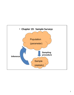
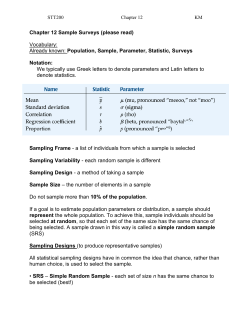


© Copyright 2026