
Engineering Data and Installation Manual *20D082-06NN* ST MODELS SPLIT SYSTEM WATER-TO-AIR HEAT PUMPS
Engineering Data and Installation Manual ST MODELS SPLIT SYSTEM WATER-TO-AIR HEAT PUMPS REVISION: 05 AUG 2014G *20D082-06NN* 20D082-06NN Table of Contents: Section 1: Model Nomenclature Model Nomenclature.................................................................................................................4 - 5 Section 2: AHRI Performance Data Ground Loop & Open Loop............................................................................................................6 Section 3: Physical & Dimensional Data Compressor Section Data., MPD Air Handlers, ACD/MCD Cased/Uncased Coils.............7 - 9 Section 4: Electrical Data Unit Electrical Data.................................................................................................................10 - 11 Section 5: Specification Glossary & Calculations Glossary & Flow Rate Calculations.......................................................................................12 - 13 Section 6 Performance Data Unit Performance Data..........................................................................................................14 - 19 Section 7: Installation Introduction Introduction, Pre-Installation, Components.........................................................................20 - 21 Section 8: Installation Considerations Installation Considerations............................................................................................................22 Section 9: Installation Unit Placement...............................................................................................................................23 A: Ductwork Installation..........................................................................................................24 - 25 B: Filter Drier Installation.................................................................................................................26 C: Line Set Installation / Charging........................................................................................27 - 37 Section 10: Unit Piping Installation Interior Piping, Water Quality.................................................................................................38 - 42 Section 11: Antifreeze Overview.........................................................................................................................................43 Anitfreeze Charging...............................................................................................................44 - 45 Section 12: Desuperheater Installation Installation................................................................................................................................46 - 48 Section 13: Controls Controls & Wiring Diagrams...................................................................................................49 - 59 Section 14: Accessories APSMA Pump Sharing Module......................................................................................................60 Section 15: Troubleshooting Troubleshooting.......................................................................................................................61 - 70 Section 16: Forms Troubleshooting, Unit Start-Up, Warranty..............................................................................71 - 70 Revision Table.................................................................................................................................78 Section 1a: Model Nomenclature Air Handlers Enertech Global 4 ST Models, 05 Aug 2014G Section 1d: Air Handler/”A” Coil Model Nomenclature Cased “A” Coils “A” Coils ST Models, 05 Aug 2014G 5 Enertech Global Section 2: AHRI Performance Data Ground Loop Heat Pump MODEL ST024 ST036 ST048 ST060 ST072 CAPACITY Full Load Part Load Full Load Part Load Full Load Part Load Full Load Part Load Full Load Part Load HEATING Btu/hr COP 18,600 3.4 14,400 3.8 28,400 3.7 22,600 4.2 35,900 3.8 27,900 4.2 44,200 3.5 34,700 3.9 51,200 3.4 41,500 3.7 COOLING Btu/hr EER 24,900 16.1 18,300 22.1 38,000 16.5 28,900 23.9 48,600 18.7 39,400 26.4 62,200 16.8 47,400 22.5 67,800 15.9 53,700 22.1 Note: Rated in accordance with ISO Standard 13256-1 which includes Pump Penalties. Heating capacities based on 68.0°F DB, 59.0°F WB entering air temperature. Cooling capacities based on 80.6°F DB, 66.2°F WB entering air temperature. Entering water temperatures Full Load: 32°F heating / 77°F cooling. Entering water temperatures Part Load: 41°F heating / 68°F cooling. Ground Water Heat Pump MODEL ST024 ST036 ST048 ST060 ST072 CAPACITY Full Load Part Load Full Load Part Load Full Load Part Load Full Load Part Load Full Load Part Load HEATING Btu/hr COP 23,500 4.2 16,200 4.1 36,400 4.4 25,600 4.8 44,600 4.5 31,800 4.9 55,400 4.1 39,400 4.4 63,700 4.1 46,700 4.1 COOLING Btu/hr EER 26,900 20.8 19,100 26.8 40,600 21.9 30,100 28.8 53,200 24.0 40,900 30.5 65,900 21.0 49,100 26.3 71,700 20.2 55,600 26.0 Note: Rated in accordance with ISO Standard 13256-1 which includes Pump Penalties. Heating capacities based on 68.0°F DB, 59.0°F WB entering air temperature. Cooling capacities based on 80.6°F DB, 66.2°F WB entering air temperature. Entering water temperatures: 50°F heating / 59°F cooling. *ST072 with ACD060C does not qualify for ENERGY STAR on Ground Water Ratings Enertech Global 6 ST Models, 05 Aug 2014G Section 3a: Unit Dimensional and Physical Data B C Suction Liquid Sweat Connections A Source Water In Source Water Out Desuperheater Out Desuperheater In Refrigeration Connection A B C Liquid Suction IN OUT IN OUT Unit Weight (Pounds) 024 18.8 22.0 25.5 3/8” 7/8” 1.0” 1.0” 3/4” 3/4” 180 036 21.8 26.0 30.5 3/8” 7/8” 1.0” 1.0” 3/4” 3/4” 225 048 22.8 26.0 30.5 3/8” 7/8” 1.0” 1.0” 3/4” 3/4” 270 060 22.8 26.0 30.5 1/2” 1-1/8” 1.0” 1.0” 3/4” 3/4” 270 072 22.8 28.0 30.5 1/2” 1-1/8” 1.0” 1.0” 3/4” 3/4” 295 Model Dimensional Data Water Loop* Desuperheater * Water loop fittings are Double O-Ring fittings on GeoComfort residential units only. Hydron Module, TETCO, and Commercial voltage units have threaded fittings. AHRI Air Handler and “A” Coil Matches Compressor Section Air Handler Match “A” Coil Match 024 MPD024A ACD024B 036 MPD036A ACD036B 048 MPD060B ACD060C 060 MPD060B ACD060C 072 MPD072A ACD060C ST Models, 05 Aug 2014G ⚠ NOTICE ⚠ WHEN MATCHING AN ST048 OR ST060 WITH AN MPD060B, REFER TO THE CFM CHART ON PAGE 56 FOR THE PROPER AIRFLOW JUMPER SETTINGS. 7 Enertech Global Section 3b: Air Handler Dimensional and Physical Data Shown with optional field-installed electric heat Line Set Connection Alternate Drain (Horizontal) Primary Drain (Horizontal) Alternate Drain (Vertical) Primary Drain (Vertical) Model MPD024A Size (tons) All Dimensions in Inches A B C D E F G H J K L M N P R 2 17 5/8 43 21 15 5/8 12 1/2 13 1/2 11 6 3/4 16 3/4 14 11 10 3/4 2 1 1/2 5 MPD036A 3 21 1/8 48 21 19 12 1/2 14 1/2 13 6 3/4 20 17 12 3/4 10 1/4 2 1/4 4 3/8 5 MPD060B 4-5 24 5/8 58 7/8 21 3/4 22 1/4 14 1/4 19 3/4 17 1/4 6 3/4 26 23 16 3/4 14 3/8 4 1/4 4 3/8 4 1/2 MPD072A 6 24 5/8 58 7/8 21 3/4 22 1/4 14 1/4 19 3/4 17 1/4 6 3/4 26 23 16 3/4 14 3/8 4 1/4 4 3/8 4 1/2 Return Air Opening Model Width Depth MPD024A 15 1/2 19 3/4 MPD036A 19 3/4 19 3/4 MPD060B 23 1/2 20 3/4 MPD072A 23 1/2 20 3/4 Shown with optional field-installed electric heat Enertech Global 8 ST Models, 05 Aug 2014G Section 3c: “A” Coil Dimensional and Physical Data C B A Size (tons) Model ACD024B ACD036B ACD060C A 16 5/8 19 5/8 23 3/4 2 3 4-6 All Dimensions in Inches C Liquid 14 1/2 3/8 18 1/2 3/8 27 7/8 3/8 B 19 19 20 1/2 Suction 3/4 3/4 7/8 All Dimensions In Inches (nominal) Model Size (Tons) A B C D E F 024 2 17.5 21.0 20.0 15.2 19.2 2.1 G H 4.1 1.8 I J 2.3 11.1 K 8.5 L 13.8 M 9.2 N 11.0 O P Q Weight (lbs) 3.3 .88 .38 45 036 3 21.0 21.0 24.0 18.7 19.2 2.2 4.3 1.8 2.3 12.9 10.6 15.7 11.9 14.2 3.3 .88 .38 50 060 5 24.5 22.0 34.0 22.0 19.9 2.2 4.2 1.9 2.3 17.3 12.8 19.8 24.8 26.8 3.3 .88 .38 72 NOTES: 1. The AC series coils are designed as high efficiency “A” coils to be installed on new and existing indoor furnaces. These coils may be used in upflow and downflow applications. 2. Coils are ETL and CSA approved. 3. Primary and secondary drain connections are available on the LH or RH side of the drain pan, and are 3/4” FPT. Center line of drains located from pan corner, 1 1/2” for primary and 3 1/2” for secondary. 4. Drain pan is injection molded high temperature UL approved plastic. 5. All coils are equipped with factory-installed TXV, 15% bleed type. ST Models, 05 Aug 2014G 9 ⚠ WARNING ⚠ IF USING A DUAL FUEL APPLICATION, “A” COIL MUST BE INSTALLED ON THE OUTLET OF THE FURNACE. INSTALLATION ON THE RETURN COULD CAUSE FURNACE HEAT EXCHANGER FAILURE, AND MAY VOID FURNACE WARRANTY. Enertech Global Section 4a: Unit Electrical Data Model 024 036 048 060 072 60Hz Power Compressor Volts Phase LRA RLA HWG Pump FLA 0 208/230 1 58.3 11.7 N/A 1 208/230 1 58.3 11.7 0.5 4.0 16.2 19.1 30 14 39 2 208/230 3 55.4 6.5 N/A N/A 6.5 8.1 15 14 99 0 208/230 1 83.0 15.3 N/A N/A 15.3 19.1 30 14 42 1 208/230 1 83.0 15.3 0.5 4.0 19.8 23.6 35 12 50 2 208/230 3 73.0 11.6 N/A N/A 11.6 14.5 25 14 55 0 208/230 1 104.0 21.2 N/A N/A 21.2 26.5 45 10 78 1 208/230 1 104.0 21.2 0.5 5.5 27.2 32.5 50 8 94 2 208/230 3 83.1 14.0 N/A N/A 14.0 17.5 30 14 46 0 208/230 1 152.9 27.1 N/A N/A 27.1 33.9 60 8 94 1 208/230 1 152.9 27.1 0.5 5.5 33.1 39.9 60 8 77 2 208/230 3 110.0 16.5 N/A N/A 16.5 20.6 35 12 60 0 208/230 1 179.2 29.7 N/A N/A 29.7 37.1 60 8 86 Voltage Code Ext Loop Pump FLA* Total Unit FLA Min Circuit AMPS Max Fuse HACR Min AWG Max Ft N/A 11.7 14.6 25 14 55 1 208/230 1 179.2 29.7 0.5 5.5 35.7 43.1 70 6 114 2 208/230 3 136.0 17.6 N/A N/A 17.6 22.0 40 12 56 Notes: 1. All line and low voltage wiring must adhere to the National Electrical Code and Local Codes, whichever is the most stringent. 2. Wire length based on a one way measurement with a 2% voltage drop. 3. Wire size based on 60°C copper conductor and minimum circuit ampacity. 3. All fuses class RK-5 4. Min/Max Voltage: 208/230/60/1 = 187/252, 208/230/60/3 = 187/252 * The external loop pump FLA is based on a maximum of three UP26-116F-230V pumps (1/2hp) for 048 - 062 and two pumps for 024 - 038 NOTE: Proper Power Supply Evaluation When any compressor bearing unit is connected to a weak power supply, starting current will generate a significant “sag” in the voltage which reduces the starting torque of the compressor motor and increases the start time. This will influence the rest of the electrical system in the building by lowering the voltage to the lights. This momentary low voltage causes “light dimming”. The total electrical system should be evaluated with an electrician and HVAC technician. The evaluation should include all connections, sizes of wires, and size of the distribution panel between the unit and the utility’s connection. The transformer connection and sizing should be evaluated by the electric utility provider. ⚠ CAUTION ⚠ CHECK COMPRESSOR AMP DRAW TO VERIFY COMPRESSOR ROTATION ON THREE PHASE UNITS. COMPARE AGAINST UNIT ELECTRICAL TABLES. REVERSE ROTATION RESULTS IN HIGHER SOUND LEVELS, LOWER AMP DRAW, AND INCREASED COMPRESSOR WEAR. THE COMPRESSOR INTERNAL OVERLOAD WILL TRIP AFTER A SHORT PERIOD OF OPERATION. Enertech Global 10 ST Models, 05 Aug 2014G Section 4a: Unit Electrical Data Section 4b: Air Handler Section Unit Electrical Data Model 60 HZ Power Volts Phase MPD024A 208/230 1 MPD036A 208/230 1 MPD060B MPD072A 208/230 208/230 1 1 Field-Installed Elect Heat # Circuits kW 1 None 0 1 10 None 0 1 10 Motor Amps / HP 2.8 / 0.33 4.3 / 0.50 Minimum Circuit Ampacity2 Maximum Fuse Size2 3.5 10 54.9 60 5.4 10 56.4 60 2 15 30.3 / 56.4 40 / 70 None 0 8.5 15 1 10 2 15 6.8 / 1.0 58.9 70 32.8 / 58.9 40 / 70 2 20 58.9 / 58.9 70 / 70 None 0 8.5 15 1 10 2 15 2 20 6.8 / 1.0 58.9 70 32.8 / 58.9 40 / 70 58.9 / 58.9 70 / 70 Notes: 1. Nominal kW at 240V. Derate 25% for 208V. 2. Units with field-installed electric heat 15kW and larger have two circuits. Data shown as “XX/XX” refers to circuit 1 before the “/” and circuit 2 after the “/” 3. Always refer to unit nameplate data prior to installation ST Models, 05 Aug 2014G 11 Enertech Global Section 5: Specification Glossary & Calculations Glossary of Terms CFM = Airflow, Cubic Feet/Minute HR = Total Heat Of Rejection, Btu/hr COP = Coefficient of Performance = BTU Output / BTU Input KW = Total Power Unit Input, Kilowatts DH = Desuperheater Capacity, Btu/hr LAT = Leaving Air Temperature, Fahrenheit EAT = Entering Air Temperature, Fahrenheit (Dry Bulb/Wet Bulb) LC = Latent Cooling Capacity, Btu/hr EER = Energy Efficiency Ratio = BTU output/Watts input SC = Sensible Cooling Capacity, Btu/hr EWT = Entering Source Water Temperature, Fahrenheit LWT = Leaving Source Water Temperature, Fahrenheit ELT = Entering Load Water Temperature, Fahrenheit LLT = Leaving Load Water Temperature, Fahrenheit GPM = Water Flow, Gallons Per Minute TC = Total Cooling Capacity, Btu/hr HC = Total Heating Capacity, Btu/hr WPD = Water Pressure Drop, PSI & Feet of Water HE = Total Heat Of Extraction, Btu/hr Heating & Cooling Calculations Heating LAT = EAT + HC CFM x 1.08 LWT = EWT - HE GPM x 500 Cooling LAT (DB) = EAT (DB) LWT = EWT + SC CFM x 1.08 HR GPM x 500 LC = TC - SC Enertech Global 12 ST Models, 05 Aug 2014G Section 5: Water Flow Selection Water Flow Selection Proper flow rate is crucial for reliable operation of geothermal heat pumps. The performance data shows three flow rates for each entering water temperature (EWT column). The general “rule of thumb” when selecting flow rates is the following: Top flow rate: Open loop systems (1.5 to 2.0 gpm per ton) Middle flow rate: Minimum closed loop system flow rate (2.25 to 2.50 gpm/ton) Bottom flow rate: Nominal (optimum) closed loop system flow rate (3.0 gpm/ton) Although the “rule of thumb” is adequate in most areas of North America, it is important to consider the application type before applying this “rule of thumb.” Antifreeze is generally required for all closed loop (geothermal) applications. Extreme Southern U.S. locations are the only exception. Open loop (well water) systems cannot use antifreeze, and must have enough flow rate in order to avoid freezing conditions at the Leaving Source Water Temperature (LWT) connection. Calculations must be made for all systems without antifreeze to determine if the top flow rate is adequate to prevent LWT at or near freezing conditions. The following steps should taken in making this calculation: Determine minimum EWT based upon your geographical area. Go to the performance data table for the heat pump model selected and look up the the Heat of Extraction (HE) at the “rule of thumb” water flow rate (GPM) and at the design Entering Air Temperature (EAT). Calculate the temperature difference (TD) based upon the HE and GPM of the model (step 4). TD = HE / (GPM x 500). Calculate the LWT (step 6). LWT = EWT - TD. If the LWT is below 35-38°F, there is potential for freezing conditions if the flow rate or water temperature is less than ideal conditions, and the flow rate must be increased. Example 1: EWT = 50°F. 3-Ton Model, high capacity. Flow rate = 5 GPM. HE = 26,900 Btuh. TD = 26,900 / (5 x 500) = 10.8°F LWT = 50 - 10.8 = 39.2°F Water flow rate should be adequate under these conditions. Example 2: EWT = 40°F. 3-Ton Model, high capacity. Flow rate = 5 GPM. HE = 23,200 Btuh. TD = 23,200 / (5 x 500) = 9.3°F LWT = 40 - 9.3 = 30.7°F Water flow rate must be increased. Performance Data Notes 1. Capacity data is based upon 15% (by volume) methanol antifreeze solution. 2. Desuperheater capacity is based upon 0.4 GPM Flow per nominal ton at 90°F entering hot water temperature. 3. Interpolation between above categories is permissible; extrapolation is not. 4. See Flow Rate Selection above for proper application. ST Models, 05 Aug 2014G 13 Enertech Global GST024C1CB Load Operation Section 6b:FullModel 024 with MPD024A Performance Data: 2.0 Ton, 900 Nominal CFM Heating; 950 Nominal CFM Cooling Full Load, 900 CFM Cooling / 900 CFM Heating EWT Flow °F GPM 25 30 40 50 60 70 80 90 100 110 6.0 5.2 Cooling COP DH Aiflow TC SC HR EER DH S/T kW Btuh/W MBtuh W/W MBtuh CFM MBtuh MBtuh MBtuh 1.63 3.06 2.3 1.51 3.30 2.3 1.60 3.37 2.5 1.48 3.64 2.5 1.61 3.42 2.5 1.50 3.67 2.5 1.63 3.42 2.5 Operation Not Recommended 1.51 3.69 2.5 1.66 3.67 2.8 1.54 3.96 2.8 1.68 3.71 2.8 1.56 4.00 2.8 1.70 3.71 2.9 1.58 3.99 3.0 1.73 3.93 3.1 950 33.4 20.1 0.60 38.1 1.37 24.4 2.4 1.61 4.22 3.1 925 32.8 20.1 0.61 37.5 1.39 23.6 2.4 1.75 3.97 3.1 950 33.6 19.2 0.57 38.1 1.33 25.3 2.1 1.62 4.29 3.1 925 33.0 19.2 0.58 37.6 1.35 24.4 2.1 1.76 3.98 3.2 950 33.8 19.1 0.57 38.3 1.31 25.8 2.0 1.64 4.27 3.2 925 33.2 19.1 0.58 37.7 1.33 25.0 2.0 1.78 4.30 3.5 950 32.6 20.0 0.61 37.7 1.50 21.7 3.0 1.65 4.63 3.5 925 32.0 20.0 0.63 37.2 1.51 21.2 3.0 1.80 4.33 3.5 950 32.8 19.1 0.58 37.8 1.46 22.5 2.7 1.67 4.67 3.6 925 32.2 19.1 0.59 37.2 1.47 21.9 2.7 1.82 4.33 3.6 950 33.0 19.0 0.58 37.9 1.43 23.1 2.5 1.69 4.66 3.8 925 32.4 19.0 0.59 37.3 1.45 22.3 2.5 1.84 4.60 3.8 950 31.6 19.8 0.63 37.2 1.65 19.2 3.5 1.71 4.95 3.8 925 31.1 19.8 0.64 36.8 1.67 18.6 3.5 1.86 4.66 3.9 950 31.9 18.9 0.59 37.4 1.61 19.8 3.2 1.73 5.01 3.9 925 31.3 18.9 0.60 36.9 1.63 19.2 3.2 1.88 4.64 4.0 950 32.0 18.8 0.59 37.4 1.58 20.3 3.0 1.74 5.02 4.0 925 31.4 18.8 0.60 36.9 1.60 19.6 3.0 1.93 4.75 4.1 950 30.4 19.2 0.63 36.5 1.80 16.9 4.0 1.79 5.12 4.2 925 29.8 19.2 0.64 36.0 1.83 16.3 4.0 1.95 4.81 4.3 950 30.6 18.3 0.60 36.6 1.76 17.4 3.6 1.81 5.18 4.3 925 30.1 18.3 0.61 36.2 1.78 16.9 3.6 1.97 4.80 4.3 950 30.8 18.2 0.59 36.7 1.73 17.8 3.5 1.83 5.17 4.4 925 30.2 18.2 0.60 36.2 1.75 17.3 3.5 2.01 4.90 4.4 950 28.9 18.4 0.64 35.8 2.03 14.2 4.4 1.87 5.26 4.4 925 28.3 18.4 0.65 35.3 2.05 13.8 4.4 2.03 4.97 4.6 950 29.1 17.6 0.60 35.8 1.97 14.8 4.0 1.89 5.33 4.6 925 28.5 17.6 0.62 35.3 2.00 14.3 4.0 2.06 4.94 4.6 950 29.2 17.5 0.60 35.8 1.94 15.1 3.9 1.91 5.32 4.6 925 28.7 17.5 0.61 35.4 1.96 14.6 3.9 950 27.1 17.9 0.66 35.2 2.36 11.5 5.0 925 26.6 17.9 0.67 34.8 2.39 11.1 5.0 950 27.3 17.0 0.62 35.1 2.30 11.9 4.5 925 26.8 17.0 0.63 34.7 2.32 11.6 4.5 950 27.5 17.0 0.62 35.2 2.26 12.2 4.4 925 26.9 17.0 0.63 34.7 2.28 11.8 4.4 Operation Not Recommended 950 25.3 17.3 0.68 34.6 2.72 9.3 5.5 925 24.8 17.3 0.70 34.2 2.75 9.0 5.5 950 25.4 16.5 0.65 34.4 2.65 9.6 5.0 925 25.0 16.5 0.66 34.1 2.68 9.3 5.0 950 25.6 16.4 0.64 34.5 2.60 9.8 4.8 925 25.1 16.4 0.65 34.1 2.63 9.5 4.8 Heating Aiflow HC HE LAT CFM MBtuh MBtuh °F 900 17.0 11.4 87.5 12.1 975 17.0 11.8 86.1 900 18.4 12.9 88.9 5.9 975 18.4 13.3 87.5 900 18.8 13.3 89.3 8.4 975 18.8 13.7 87.9 900 19.0 13.4 89.5 11.7 975 19.0 13.8 88.0 900 20.8 15.1 91.4 5.4 975 20.8 15.5 89.8 900 21.3 15.6 91.9 7.7 975 21.3 16.0 90.2 900 21.5 15.7 92.1 10.7 975 21.5 16.1 90.4 900 23.2 17.3 93.9 4.9 975 23.2 17.7 92.0 900 23.7 17.7 94.4 7.1 975 23.7 18.2 92.5 900 23.9 17.9 94.6 9.8 975 23.9 18.3 92.7 900 26.1 20.0 96.9 4.6 975 26.1 20.5 94.8 900 26.6 20.5 97.4 6.5 975 26.6 20.9 95.3 900 26.9 20.7 97.7 9.0 975 26.9 21.1 95.5 900 28.9 22.6 99.7 4.3 975 28.9 23.1 97.4 900 29.6 23.3 100.5 6.1 975 29.6 23.7 98.1 900 29.8 23.4 100.7 8.5 975 29.8 23.9 98.3 900 31.3 24.7 102.2 4.0 975 31.3 25.2 99.7 900 32.0 25.3 102.9 5.7 975 32.0 25.8 100.4 900 32.3 25.6 103.2 8.0 975 32.3 26.1 100.7 900 33.6 26.7 104.6 3.8 975 33.6 27.2 101.9 900 34.4 27.5 105.4 5.4 975 34.4 27.9 102.7 900 34.7 27.7 105.7 7.5 975 34.7 28.2 103.0 WPD PSI FT 4.0 2.5 5.0 3.6 6.0 5.0 4.0 2.3 5.0 3.3 6.0 4.6 4.0 2.1 5.0 3.1 6.0 4.2 4.0 2.0 5.0 2.8 6.0 3.9 4.0 1.8 5.0 2.6 6.0 3.7 4.0 1.7 5.0 2.5 6.0 3.4 4.0 1.6 5.0 2.3 6.0 3.2 4.0 1.5 3.6 5.0 2.2 5.1 6.0 3.1 7.0 4.0 1.4 3.3 5.0 2.1 4.8 6.0 2.9 6.6 kW Heating data based on 70F EAT; Cooling data based on 80/67F EAT. See Correction Factors on page 24 for different conditions. Notes: 1. Capacity data includes water pumping watts and is based upon 15% (by volume) propylene glycol antifreeze solution. 2. Desuperheater capacity is based upon 0.4 GPM Flow per nominal ton at 90°F entering hot water temperature. 3. Interpolation between above catagories is permissible; extrapolation is not. 4. See Flow Rate Selection on page 7 for proper application. Enertech Global 14 ST Models, 05 Aug 2014G GST036C1CB Load Operation Section 6d:FullModel 036 with MPD036A Performance Data: 3.0 Ton, 1350 Nominal CFM Heating; 1350 Nominal CFM Cooling Full Load, 1350 CFM Cooling / 1350 CFM Heating EWT Flow °F GPM 25 30 40 50 60 70 80 90 100 110 9.0 WPD PSI FT 3.8 8.8 5.0 1.5 3.5 7.0 2.5 5.8 9.0 3.7 8.6 5.0 1.4 3.2 7.0 2.4 5.5 9.0 3.5 8.0 5.0 1.3 3.0 7.0 2.2 5.1 9.0 3.2 7.5 5.0 1.2 2.8 7.0 2.1 4.7 9.0 3.0 7.0 5.0 1.1 2.6 7.0 1.9 4.5 9.0 2.8 6.6 5.0 1.1 2.5 7.0 1.8 4.2 9.0 2.7 6.2 5.0 1.0 2.4 7.0 1.8 4.1 9.0 2.6 6.0 5.0 1.0 2.4 7.0 1.7 4.0 9.0 2.6 5.9 5.0 1.1 2.5 7.0 1.8 4.3 9.0 2.7 6.2 Cooling COP DH Aiflow TC SC HR EER DH S/T kW Btuh/W MBtuh W/W MBtuh CFM MBtuh MBtuh MBtuh 2.50 3.20 3.7 2.42 3.20 3.6 2.50 3.31 3.8 2.42 3.32 3.7 2.51 3.34 3.8 2.43 3.35 3.7 2.53 3.38 3.8 Operation Not Recommended 2.45 3.38 3.7 2.60 3.63 4.2 2.52 3.63 4.2 2.62 3.65 4.3 2.53 3.67 4.3 2.64 3.70 4.3 2.56 3.70 4.5 2.72 3.90 4.7 1350 41.4 29.1 0.70 48.3 2.02 20.5 3.4 2.63 3.91 4.6 1150 41.2 28.3 0.69 47.7 1.90 21.7 3.3 2.73 3.94 4.8 1350 41.7 29.0 0.70 48.6 2.01 20.7 3.2 2.64 3.95 4.7 1150 41.5 28.2 0.68 48.0 1.90 21.8 3.1 2.75 3.98 4.9 1350 41.9 29.0 0.69 48.6 1.96 21.4 3.1 2.66 4.00 4.8 1150 41.7 28.1 0.67 48.0 1.85 22.5 3.0 2.83 4.15 5.2 1350 40.4 28.9 0.72 48.0 2.22 18.2 4.2 2.73 4.17 5.2 1150 40.2 28.0 0.70 47.3 2.09 19.2 4.1 2.84 4.19 5.4 1350 40.7 28.8 0.71 48.3 2.22 18.3 4.0 2.75 4.20 5.4 1150 40.5 27.9 0.69 47.6 2.09 19.4 3.9 2.87 4.24 5.5 1350 40.9 28.7 0.70 48.3 2.16 18.9 3.8 2.77 4.25 5.6 1150 40.7 27.9 0.69 47.7 2.04 20.0 3.7 2.95 4.37 5.8 1350 39.3 28.6 0.73 47.7 2.47 15.9 5.0 2.85 4.39 5.6 1150 39.1 27.7 0.71 47.1 2.33 16.8 4.8 2.96 4.41 6.0 1350 39.5 28.5 0.72 47.9 2.47 16.0 4.8 2.87 4.42 5.8 1150 39.3 27.6 0.70 47.2 2.32 16.9 4.6 2.99 4.47 6.1 1350 39.7 28.4 0.72 47.9 2.40 16.5 4.5 2.89 4.48 5.9 1150 39.5 27.5 0.70 47.2 2.26 17.5 4.4 3.10 4.54 6.3 1350 37.1 27.7 0.75 46.5 2.74 13.5 5.7 2.99 4.57 6.4 1150 36.9 26.9 0.73 45.7 2.58 14.3 5.5 3.11 4.59 6.4 1350 37.3 27.6 0.74 46.6 2.73 13.7 5.4 3.01 4.59 6.5 1150 37.2 26.7 0.72 46.0 2.58 14.4 5.2 3.14 4.64 6.6 1350 37.5 27.5 0.73 46.6 2.66 14.1 5.3 3.04 4.65 6.7 1150 37.3 26.7 0.72 45.9 2.51 14.9 5.1 3.25 4.69 6.9 1350 34.5 26.6 0.77 45.0 3.09 11.2 6.4 3.14 4.71 6.7 1150 34.3 25.8 0.75 44.2 2.91 11.8 6.2 3.26 4.75 7.0 1350 34.8 26.5 0.76 45.3 3.08 11.3 6.0 3.16 4.75 6.8 1150 34.6 25.7 0.74 44.5 2.90 11.9 5.8 3.29 4.80 7.2 1350 34.9 26.4 0.76 45.1 3.00 11.6 5.9 3.19 4.80 7.0 1150 34.7 25.6 0.74 44.3 2.82 12.3 5.7 1350 32.3 25.7 0.80 44.4 3.55 9.1 7.1 1150 32.1 24.9 0.78 43.5 3.35 9.6 6.9 1350 32.5 25.6 0.79 44.6 3.54 9.2 6.7 1150 32.4 24.8 0.77 43.8 3.34 9.7 6.5 1350 32.7 25.5 0.78 44.5 3.45 9.5 6.6 1150 32.5 24.7 0.76 43.6 3.25 10.0 6.4 Operation Not Recommended 1350 30.0 24.7 0.82 43.9 4.06 7.4 7.9 1150 29.8 23.9 0.80 42.9 3.83 7.8 7.6 1350 30.2 24.6 0.81 44.0 4.05 7.5 7.4 1150 30.0 23.8 0.79 43.0 3.82 7.9 7.2 1350 30.3 24.5 0.81 43.8 3.95 7.7 7.2 1150 30.2 23.8 0.79 42.9 3.72 8.1 7.0 Heating Aiflow HC HE LAT CFM MBtuh MBtuh °F 1350 27.3 18.8 88.7 1150 26.4 18.1 91.3 1350 28.2 19.7 89.3 1150 27.4 19.1 92.1 1350 28.6 20.0 89.6 1150 27.8 19.5 92.4 1350 29.2 20.6 90.0 1150 28.3 19.9 92.8 1350 32.2 23.3 92.1 1150 31.2 22.6 95.1 1350 32.6 23.7 92.4 1150 31.7 23.1 95.5 1350 33.3 24.3 92.8 1150 32.3 23.6 96.0 1350 36.2 26.9 94.8 1150 35.1 26.1 98.3 1350 36.7 27.4 95.2 1150 35.6 26.6 98.7 1350 37.4 28.0 95.7 1150 36.3 27.2 99.2 1350 40.1 30.4 97.5 1150 38.9 29.6 101.3 1350 40.6 30.9 97.8 1150 39.4 30.0 101.7 1350 41.5 31.7 98.5 1150 40.2 30.7 102.4 1350 44.0 33.9 100.2 1150 42.7 33.0 104.4 1350 44.6 34.5 100.6 1150 43.3 33.5 104.9 1350 45.6 35.4 101.3 1150 44.2 34.3 105.6 1350 48.0 37.4 102.9 1150 46.6 36.4 107.5 1350 48.7 38.1 103.4 1150 47.2 36.9 108.0 1350 49.7 39.0 104.1 1150 48.2 37.8 108.8 1350 52.0 40.9 105.7 1150 50.5 39.8 110.7 1350 52.8 41.7 106.2 1150 51.2 40.4 111.2 1350 53.9 42.7 107.0 1150 52.3 41.4 112.1 kW Heating data based on 70F EAT; Cooling data based on 80/67F EAT. See Correction Factors on page 24 for different conditions. Notes: 1. Capacity data includes water pumping watts and is based upon 15% (by volume) propylene glycol antifreeze solution. 2. Desuperheater capacity is based upon 0.4 GPM Flow per nominal ton at 90°F entering hot water temperature. 3. Interpolation between above catagories is permissible; extrapolation is not. 4. See Flow Rate Selection on page 7 for proper application. ST Models, 05 Aug 2014G 15 Enertech Global GST048C1CB Load Operation Section 6f:Full Model 048 with MPD060B Performance Data: 4.0 Ton, 1600 Nominal CFM Heating; 1650 Nominal CFM Cooling Full Load, 1650 CFM Cooling / 1600 CFM Heating EWT Flow °F GPM 25 30 40 50 60 70 80 90 100 110 WPD PSI FT 12.0 7.1 16.4 7.0 2.8 6.4 9.0 4.2 9.7 12.0 6.9 15.9 7.0 2.6 6.0 9.0 3.9 9.1 12.0 6.4 14.9 7.0 2.4 5.6 9.0 3.7 8.5 12.0 6.0 13.9 7.0 2.3 5.3 9.0 3.5 8.0 12.0 5.7 13.1 7.0 2.2 5.0 9.0 3.3 7.6 12.0 5.4 12.5 7.0 2.1 4.8 9.0 3.1 7.3 12.0 5.2 11.9 7.0 2.0 4.6 9.0 3.0 7.0 12.0 4.9 11.4 7.0 1.9 4.4 9.0 2.9 6.7 12.0 4.8 11.0 7.0 1.9 4.4 9.0 2.8 6.6 12.0 4.7 10.8 Heating Aiflow HC HE LAT CFM MBtuh MBtuh °F 1600 37.1 26.9 91.5 1500 37.0 26.7 92.8 1600 36.2 25.9 90.9 1500 36.2 25.9 92.3 1600 37.0 26.7 91.4 1500 36.9 26.6 92.8 1600 37.9 27.6 91.9 1500 37.9 27.5 93.4 1600 41.0 30.4 93.7 1500 40.9 30.2 95.2 1600 41.9 31.3 94.2 1500 41.8 31.1 95.8 1600 42.9 32.2 94.8 1500 42.8 32.1 96.4 1600 45.4 34.4 96.3 1500 45.3 34.3 98.0 1600 46.4 35.4 96.9 1500 46.3 35.3 98.6 1600 47.5 36.5 97.5 1500 47.4 36.3 99.3 1600 48.2 37.0 97.9 1500 48.0 36.8 99.6 1600 49.2 38.0 98.5 1500 49.1 37.9 100.3 1600 50.4 39.2 99.2 1500 50.3 39.0 101.0 1600 50.2 38.8 99.1 1500 50.1 38.7 100.9 1600 51.3 39.9 99.7 1500 51.2 39.8 101.6 1600 52.5 41.1 100.4 1500 52.4 40.9 102.3 1600 52.7 41.1 100.5 1500 52.6 41.0 102.5 1600 53.8 42.2 101.1 1500 53.7 42.1 103.1 1600 55.2 43.6 101.9 1500 55.0 43.3 104.0 1600 54.9 43.2 101.8 1500 54.8 43.0 103.8 1600 56.1 44.4 102.5 1500 56.0 44.2 104.6 1600 57.5 45.7 103.3 1500 57.3 45.5 105.4 Cooling COP DH Aiflow TC SC HR EER S/T kW W/W MBtuh CFM MBtuh MBtuh MBtuh Btuh/W 3.00 3.62 4.9 3.02 3.59 4.9 3.02 3.51 4.8 3.03 3.50 4.8 3.01 3.60 4.9 3.03 3.57 4.9 3.03 3.66 5.0 Operation Not Recommended 3.04 3.65 5.0 3.12 3.85 5.4 3.13 3.83 5.5 3.11 3.95 5.5 3.13 3.91 5.6 3.13 4.02 5.7 3.14 3.99 5.9 3.21 4.14 6.0 1650 57.4 39.4 0.69 65.7 2.44 23.5 3.23 4.11 6.0 1525 57.0 38.0 0.67 65.2 2.39 23.8 3.21 4.24 6.1 1650 56.9 39.3 0.69 65.1 2.40 23.7 3.23 4.20 6.1 1525 56.5 38.0 0.67 64.5 2.35 24.0 3.22 4.32 6.3 1650 57.5 39.6 0.69 65.5 2.33 24.7 3.24 4.29 6.3 1525 57.1 38.3 0.67 64.9 2.28 25.0 3.28 4.31 6.3 1650 55.7 38.8 0.70 64.8 2.68 20.8 3.29 4.27 6.3 1525 55.4 37.5 0.68 64.3 2.62 21.1 3.28 4.39 6.5 1650 55.2 38.7 0.70 64.2 2.64 20.9 3.29 4.37 6.6 1525 54.9 37.4 0.68 63.7 2.58 21.3 3.29 4.49 6.7 1650 55.9 39.0 0.70 64.6 2.56 21.8 3.31 4.45 6.7 1525 55.5 37.7 0.68 64.1 2.51 22.1 3.33 4.42 6.5 1650 54.0 38.1 0.71 64.1 2.97 18.2 3.35 4.38 6.5 1525 53.6 36.8 0.69 63.5 2.90 18.5 3.33 4.51 6.8 1650 53.5 38.0 0.71 63.5 2.92 18.3 3.35 4.48 6.8 1525 53.1 36.7 0.69 62.9 2.86 18.6 3.34 4.61 7.0 1650 54.1 38.3 0.71 63.8 2.84 19.0 3.36 4.57 7.0 1525 53.7 37.0 0.69 63.2 2.77 19.4 3.39 4.55 6.9 1650 51.5 37.0 0.72 62.7 3.28 15.7 3.41 4.52 7.0 1525 51.1 35.8 0.70 62.0 3.20 16.0 3.39 4.65 7.1 1650 51.0 36.9 0.72 62.0 3.23 15.8 3.40 4.63 7.2 1525 50.7 35.7 0.70 61.5 3.16 16.0 3.40 4.76 7.3 1650 51.6 37.2 0.72 62.3 3.13 16.5 3.42 4.71 7.3 1525 51.2 36.0 0.70 61.6 3.06 16.7 3.44 4.68 7.2 1650 48.6 35.7 0.73 61.1 3.67 13.2 3.46 4.64 7.2 1525 48.3 34.5 0.71 60.6 3.59 13.5 3.44 4.78 7.4 1650 48.2 35.7 0.74 60.6 3.62 13.3 3.46 4.74 7.4 1525 47.8 34.4 0.72 59.9 3.54 13.5 3.45 4.88 7.6 1650 48.7 35.9 0.74 60.7 3.51 13.9 3.47 4.84 7.6 1525 48.4 34.7 0.72 60.1 3.43 14.1 1650 45.9 34.4 0.75 60.2 4.19 11.0 1525 45.5 33.2 0.73 59.5 4.09 11.1 1650 45.4 34.4 0.76 59.5 4.12 11.0 1525 45.1 33.2 0.74 58.9 4.03 11.2 1650 45.9 34.6 0.75 59.6 4.00 11.5 1525 45.6 33.5 0.73 58.9 3.91 11.7 Operation Not Recommended 1650 42.9 33.0 0.77 59.0 4.72 9.1 1525 42.7 31.9 0.75 58.5 4.62 9.2 1650 42.5 33.0 0.78 58.4 4.65 9.1 1525 42.3 31.8 0.75 57.8 4.55 9.3 1650 43.0 33.2 0.77 58.4 4.52 9.5 1525 42.7 32.1 0.75 57.8 4.42 9.7 kW DH MBtuh 4.7 4.5 4.3 4.2 4.2 4.1 5.7 5.5 5.4 5.2 5.2 5.0 6.6 6.4 6.4 6.2 6.1 5.9 7.6 7.4 7.2 7.0 7.0 6.8 8.6 8.3 8.1 7.8 8.0 7.7 9.5 9.2 9.1 8.8 8.9 8.6 10.4 10.1 10.1 9.7 9.7 9.4 Heating data based on 70F EAT; Cooling data based on 80/67F EAT. See Correction Factors on page 24 for different conditions. Notes: 1. Capacity data includes water pumping watts and is based upon 15% (by volume) propylene glycol antifreeze solution. 2. Desuperheater capacity is based upon 0.4 GPM Flow per nominal ton at 90°F entering hot water temperature. 3. Interpolation between above catagories is permissible; extrapolation is not. 4. See Flow Rate Selection on page 7 for proper application. Enertech Global 16 ST Models, 05 Aug 2014G GST060C1CB Load Operation Section 6h:FullModel 060 with MPD060B Performance Data: 5.0 Ton, 1900 Nominal CFM Heating; 1950 Nominal CFM Cooling Full Load, 1950 CFM Cooling / 1900 CFM Heating EWT Flow °F GPM 25 WPD PSI FT 15.0 9.7 22.5 8.0 7.4 17.0 12.0 7.9 18.3 15.0 9.2 21.3 8.0 6.3 14.5 12.0 6.8 15.7 15.0 7.9 18.2 8.0 5.6 12.9 12.0 6.0 13.9 15.0 7.0 16.2 8.0 5.5 12.6 12.0 5.9 13.6 15.0 6.8 15.7 8.0 5.6 12.9 12.0 6.0 13.9 15.0 7.0 16.1 8.0 5.6 12.9 12.0 6.0 13.9 15.0 7.0 16.2 8.0 5.2 12.1 12.0 5.6 13.0 15.0 6.5 15.1 8.0 4.7 10.7 100 12.0 5.0 11.6 15.0 5.8 13.4 8.0 4.8 11.1 110 12.0 5.2 12.0 15.0 6.0 13.9 30 40 50 60 70 80 90 Heating Aiflow HC HE LAT CFM MBtuh MBtuh °F 1900 44.4 31.3 91.6 1750 44.4 31.2 93.5 1900 43.1 29.9 91.0 1750 43.1 29.9 92.8 1900 44.5 31.3 91.7 1750 44.5 31.2 93.5 1900 45.4 32.2 92.1 1750 45.4 32.1 94.0 1900 48.7 35.1 93.7 1750 48.7 35.0 95.8 1900 50.3 36.6 94.5 1750 50.3 36.5 96.6 1900 51.4 37.7 95.0 1750 51.4 37.6 97.2 1900 54.0 40.0 96.3 1750 54.0 39.9 98.6 1900 55.8 41.7 97.2 1750 55.8 41.6 99.5 1900 56.9 42.8 97.7 1750 56.9 42.7 100.1 1900 57.2 42.9 97.9 1750 57.2 42.8 100.3 1900 59.2 44.9 98.8 1750 59.2 44.8 101.3 1900 60.4 46.0 99.4 1750 60.4 45.9 102.0 1900 59.6 45.1 99.0 1750 59.6 45.0 101.5 1900 61.7 47.1 100.1 1750 61.7 47.0 102.6 1900 62.9 48.3 100.7 1750 62.9 48.2 103.3 1900 62.6 47.8 100.5 1750 62.6 47.7 103.1 1900 64.7 49.9 101.5 1750 64.7 49.8 104.2 1900 66.0 51.1 102.2 1750 66.0 51.0 104.9 1900 65.2 50.2 101.8 1750 65.2 50.1 104.5 1900 67.5 52.4 102.9 1750 67.5 52.3 105.7 1900 68.8 53.7 103.5 1750 68.8 53.6 106.4 Cooling COP DH Aiflow TC SC HR EER S/T kW W/W MBtuh CFM MBtuh MBtuh MBtuh Btuh/W 3.84 3.39 5.9 3.87 3.36 5.9 3.86 3.27 5.7 3.88 3.25 5.7 3.87 3.37 5.9 3.90 3.34 5.9 3.88 3.43 6.0 Operation Not Recommended 3.90 3.41 6.0 3.98 3.59 6.4 4.01 3.56 6.5 4.00 3.68 6.6 4.03 3.66 6.7 4.00 3.77 6.8 4.03 3.74 7.0 4.10 3.86 7.1 1950 69.5 47.3 0.68 80.1 3.12 22.3 4.13 3.83 7.1 1700 68.4 44.1 0.64 78.6 3.00 22.8 4.12 3.97 7.3 1950 69.5 47.4 0.68 79.9 3.04 22.9 4.15 3.94 7.3 1700 68.4 44.3 0.65 78.4 2.92 23.4 4.13 4.04 7.5 1950 70.0 47.7 0.68 80.1 2.97 23.6 4.16 4.01 7.5 1700 68.8 44.6 0.65 78.5 2.85 24.1 4.19 4.00 7.5 1950 67.6 46.5 0.69 79.3 3.44 19.7 4.22 3.97 7.6 1700 66.4 43.5 0.66 77.7 3.30 20.1 4.20 4.13 7.8 1950 67.6 46.7 0.69 79.0 3.34 20.2 4.23 4.10 7.9 1700 66.4 43.6 0.66 77.4 3.21 20.7 4.21 4.20 8.0 1950 68.0 47.0 0.69 79.1 3.26 20.9 4.24 4.17 8.0 1700 66.8 43.9 0.66 77.5 3.14 21.3 4.26 4.10 7.8 1950 65.4 45.7 0.70 78.4 3.80 17.2 4.29 4.07 7.8 1700 64.3 42.7 0.66 76.8 3.65 17.6 4.27 4.23 8.2 1950 65.4 45.9 0.70 78.0 3.69 17.7 4.30 4.20 8.2 1700 64.3 42.8 0.67 76.4 3.55 18.1 4.28 4.31 8.4 1950 65.8 46.1 0.70 78.1 3.61 18.2 4.31 4.28 8.4 1700 64.7 43.1 0.67 76.5 3.47 18.6 4.33 4.24 8.2 1950 62.4 44.4 0.71 76.7 4.20 14.9 4.36 4.21 8.4 1700 61.3 41.5 0.68 75.1 4.03 15.2 4.35 4.36 8.6 1950 62.4 44.6 0.71 76.3 4.08 15.3 4.38 4.33 8.7 1700 61.3 41.6 0.68 74.7 3.92 15.6 4.36 4.44 8.8 1950 62.8 44.8 0.71 76.4 3.99 15.7 4.39 4.40 8.7 1700 61.7 41.9 0.68 74.8 3.83 16.1 4.40 4.34 8.6 1950 58.9 42.9 0.73 74.9 4.70 12.5 4.43 4.31 8.6 1700 57.9 40.1 0.69 73.3 4.52 12.8 4.42 4.47 8.9 1950 58.9 43.0 0.73 74.5 4.57 12.9 4.45 4.44 8.9 1700 57.9 40.2 0.69 72.9 4.39 13.2 4.42 4.56 9.2 1950 59.3 43.3 0.73 74.6 4.47 13.3 4.46 4.52 9.2 1700 58.3 40.4 0.69 72.9 4.29 13.6 1950 55.6 41.3 0.74 73.9 5.36 10.4 1700 54.6 38.6 0.71 72.2 5.15 10.6 1950 55.6 41.5 0.75 73.3 5.20 10.7 1700 54.6 38.7 0.71 71.7 5.00 10.9 1950 55.9 41.7 0.75 73.3 5.09 11.0 1700 55.0 39.0 0.71 71.7 4.89 11.2 Operation Not Recommended 1950 52.0 39.6 0.76 72.6 6.05 8.6 1700 51.2 37.0 0.72 71.1 5.82 8.8 1950 52.0 39.8 0.77 72.1 5.88 8.8 1700 51.2 37.2 0.73 70.5 5.65 9.1 1950 52.3 40.0 0.76 71.9 5.75 9.1 1700 51.5 37.4 0.73 70.4 5.53 9.3 kW DH MBtuh 5.6 5.2 5.2 4.9 5.1 4.8 6.8 6.4 6.5 6.1 6.2 5.8 8.0 7.5 7.7 7.2 7.3 6.8 9.2 8.6 8.8 8.2 8.4 7.9 10.3 9.6 9.7 9.1 9.6 9.0 11.4 10.7 10.9 10.2 10.7 10.0 12.5 11.7 12.1 11.3 11.8 11.0 Heating data based on 70F EAT; Cooling data based on 80/67F EAT. See Correction Factors on page 24 for different conditions. Notes: 1. Capacity data includes water pumping watts and is based upon 15% (by volume) propylene glycol antifreeze solution. 2. Desuperheater capacity is based upon 0.4 GPM Flow per nominal ton at 90°F entering hot water temperature. 3. Interpolation between above catagories is permissible; extrapolation is not. 4. See Flow Rate Selection on page 7 for proper application. ST Models, 05 Aug 2014G 17 Enertech Global GST072C1CB Load Operation Section 6j:Full Model 072 with MPD072A Performance Data: 6.0 Ton, 2050 Nominal CFM Heating; 2100 Nominal CFM Cooling Full Load, 2100 CFM Cooling / 2100 CFM Heating EWT Flow °F GPM 25 WPD PSI FT 18.0 10.4 24.0 12.0 5.0 11.5 15.0 7.4 17.1 18.0 10.1 23.3 12.0 4.7 10.8 15.0 6.9 16.0 18.0 9.5 21.8 12.0 4.4 10.1 15.0 6.5 15.0 18.0 8.9 20.5 12.0 4.2 9.6 15.0 6.1 14.2 18.0 8.4 19.4 12.0 4.0 9.2 15.0 5.9 13.6 18.0 8.1 18.7 12.0 3.9 9.0 15.0 5.7 13.2 18.0 7.8 18.1 12.0 3.8 8.7 15.0 5.6 12.9 18.0 7.6 17.6 12.0 3.7 8.5 100 15.0 5.4 12.5 18.0 7.4 17.1 12.0 3.5 8.2 110 15.0 5.2 12.1 18.0 7.2 16.5 30 40 50 60 70 80 90 Heating Aiflow HC HE LAT CFM MBtuh MBtuh °F 2050 51.4 35.6 93.2 1700 50.4 34.7 97.5 2050 52.5 36.7 93.7 1700 51.5 35.8 98.1 2050 53.1 37.2 94.0 1700 52.0 36.2 98.3 2050 53.1 37.1 94.0 1700 52.1 36.2 98.4 2050 59.1 42.6 96.7 1700 57.9 41.5 101.5 2050 59.7 43.1 97.0 1700 58.6 42.1 101.9 2050 59.8 43.1 97.0 1700 58.6 41.9 101.9 2050 65.2 48.0 99.4 1700 63.9 46.8 104.8 2050 65.9 48.6 99.8 1700 64.6 47.4 105.2 2050 66.0 48.6 99.8 1700 64.7 47.4 105.2 2050 69.3 51.7 101.3 1700 68.0 50.5 107.0 2050 70.1 52.4 101.7 1700 68.7 51.1 107.4 2050 70.1 52.3 101.7 1700 68.8 51.0 107.5 2050 72.3 54.4 102.7 1700 70.9 53.1 108.6 2050 73.1 55.1 103.0 1700 71.6 53.7 109.0 2050 73.1 54.9 103.0 1700 71.7 53.6 109.1 2050 75.4 57.2 104.1 1700 73.9 55.8 110.3 2050 76.2 57.9 104.4 1700 74.7 56.5 110.7 2050 76.3 57.8 104.5 1700 74.8 56.4 110.7 2050 78.0 59.6 105.2 1700 76.5 58.1 111.7 2050 78.8 60.3 105.6 1700 77.3 58.9 112.1 2050 78.9 60.2 105.6 1700 77.4 58.8 112.2 Cooling COP DH Aiflow TC SC HR EER S/T kW W/W MBtuh CFM MBtuh MBtuh MBtuh Btuh/W 4.62 3.26 6.9 4.60 3.21 6.8 4.62 3.33 7.0 4.60 3.28 6.9 4.65 3.35 7.0 4.62 3.30 6.9 4.68 3.32 7.0 Operation Not Recommended 4.66 3.28 6.9 4.84 3.58 7.8 4.81 3.53 7.8 4.86 3.60 7.8 4.84 3.55 7.8 4.90 3.58 7.8 4.88 3.52 8.2 5.03 3.80 8.7 2100 77.5 51.8 0.67 90.3 3.74 20.7 5.01 3.74 8.5 1750 76.0 47.4 0.62 88.0 3.51 21.7 5.06 3.82 8.7 2100 77.7 51.7 0.67 90.1 3.63 21.4 5.04 3.76 8.5 1750 76.2 47.3 0.62 87.9 3.42 22.3 5.10 3.79 8.7 2100 77.6 51.4 0.66 89.8 3.58 21.7 5.08 3.73 8.5 1750 76.2 47.1 0.62 87.7 3.36 22.7 5.16 3.94 9.0 2100 74.6 50.8 0.68 88.5 4.07 18.3 5.14 3.88 9.0 1750 73.1 46.5 0.64 86.1 3.82 19.1 5.19 3.96 9.1 2100 74.7 50.7 0.68 88.2 3.95 18.9 5.17 3.89 9.1 1750 73.3 46.4 0.63 86.0 3.72 19.7 5.23 3.93 9.1 2100 74.7 50.5 0.68 88.0 3.89 19.2 5.21 3.87 9.3 1750 73.3 46.2 0.63 85.8 3.66 20.0 5.25 4.03 9.5 2100 71.6 49.8 0.70 86.8 4.44 16.1 5.23 3.97 9.3 1750 70.2 45.6 0.65 84.4 4.17 16.8 5.28 4.06 9.7 2100 71.7 49.7 0.69 86.4 4.31 16.6 5.25 4.00 9.5 1750 70.3 45.5 0.65 84.2 4.06 17.3 5.32 4.03 9.7 2100 71.7 49.5 0.69 86.2 4.25 16.9 5.30 3.96 9.5 1750 70.3 45.3 0.64 84.0 4.00 17.6 5.34 4.14 9.8 2100 68.8 48.6 0.71 85.4 4.87 14.1 5.31 4.08 9.9 1750 67.5 44.5 0.66 83.1 4.58 14.7 5.36 4.17 10.0 2100 68.9 48.5 0.70 85.0 4.73 14.6 5.34 4.10 10.0 1750 67.6 44.4 0.66 82.8 4.45 15.2 5.41 4.13 10.0 2100 68.9 48.2 0.70 84.8 4.66 14.8 5.38 4.07 10.1 1750 67.6 44.2 0.65 82.6 4.39 15.4 5.40 4.23 10.3 2100 65.9 47.1 0.71 84.4 5.41 12.2 5.38 4.17 10.1 1750 64.6 43.1 0.67 82.0 5.09 12.7 5.43 4.25 10.4 2100 66.0 47.0 0.71 84.0 5.26 12.5 5.40 4.19 10.2 1750 64.7 43.1 0.67 81.6 4.94 13.1 5.47 4.23 10.5 2100 66.0 46.8 0.71 83.7 5.18 12.7 5.45 4.16 10.3 1750 64.7 42.9 0.66 81.3 4.87 13.3 2100 62.4 45.7 0.73 83.1 6.06 10.3 1750 61.2 41.9 0.68 80.7 5.70 10.7 2100 62.5 45.6 0.73 82.6 5.89 10.6 1750 61.4 41.8 0.68 80.3 5.54 11.1 2100 62.5 45.4 0.73 82.3 5.80 10.8 1750 61.3 41.6 0.68 79.9 5.45 11.2 Operation Not Recommended 2100 58.9 44.2 0.75 81.9 6.74 8.7 1750 57.8 40.5 0.70 79.4 6.34 9.1 2100 59.0 44.2 0.75 81.4 6.55 9.0 1750 57.9 40.4 0.70 78.9 6.16 9.4 2100 59.0 44.0 0.75 81.0 6.45 9.1 1750 57.9 40.2 0.69 78.6 6.07 9.5 kW DH MBtuh 6.1 5.6 5.8 5.3 5.5 5.0 7.4 6.8 7.1 6.5 6.7 6.1 8.7 8.0 8.4 7.7 7.9 7.2 10.0 9.2 9.6 8.8 9.2 8.4 11.3 10.3 10.7 9.8 10.4 9.5 12.7 11.6 12.1 11.1 11.7 10.7 14.0 12.8 13.5 12.3 12.9 11.8 Heating data based on 70F EAT; Cooling data based on 80/67F EAT. See Correction Factors on page 24 for different conditions. Notes: 1. Capacity data includes water pumping watts and is based upon 15% (by volume) propylene glycol antifreeze solution. 2. Desuperheater capacity is based upon 0.4 GPM Flow per nominal ton at 90°F entering hot water temperature. 3. Interpolation between above catagories is permissible; extrapolation is not. 4. See Flow Rate Selection on page 7 for proper application. Enertech Global 18 ST Models, 05 Aug 2014G Section 6k: Performance Data Correction Factors Heating Correction Factors EAT °F HC 50 1.0450 60 1.0260 55 65 70 75 80 1.0347 1.0089 1.0000 0.9924 0.9870 HE kW 1.1136 0.8208 1.0893 0.8567 1.0640 0.9019 1.0270 0.9497 1.0000 1.0000 0.9741 1.0527 0.9653 1.0522 Cooling Correction Factors EAT (WB) °F 55 TC HR kW 0.8215 0.8293 0.8635 0.9404 0.9431 0.9547 60 0.8955 65 0.9701 63 67 70 75 Sensible Cooling Correction Factors 1.0000 1.0446 1.1179 0.9001 0.9715 1.0000 1.0425 1.1124 ST Models, 05 Aug 2014G 0.9205 0.9774 1.0000 1.0335 1.0878 EAT (WB) °F 70 75 55 1.201 1.289 63 0.852 0.995 60 65 67 70 75 19 0.943 0.797 0.624 EAT (DB) °F 80 85 1.067 1.192 0.952 1.106 1.261 0.820 0.944 0.812 0.697 1.138 1.000 0.637 90 1.188 1.343 0.817 0.983 1.067 Enertech Global Section 7: Installation Introduction INTRODUCTION This geothermal heat pump provides heating and cooling as well as optional domestic water heating capability. Engineering and quality control is built into every geothermal unit. Good performance depends on proper application and correct installation. equivalent protective covering. Cap or recap unit connections and all piping until unit is installed. Precautions must be taken to avoid physical damage and contamination which may prevent proper start-up and may result in costly equipment repair. ⚠ CAUTION ⚠ Notices, Cautions, Warnings, & Dangers “NOTICE” Notification of installation, operation or maintenance information which is important, but which is NOT hazard-related. “CAUTION” Indicates a potentially hazardous situation or an unsafe practice which, if not avoided, COULD result in minor or moderate injury or product or property damage. “WARNING” Indicates potentially hazardous situation which, if not avoided, COULD result in death or serious injury. “DANGER” Indicates an immediate hazardous situation which, if not avoided, WILL result in death or serious injury. Inspection Upon receipt of any geothermal equipment, carefully check the shipment against the packing slip and the freight company bill of lading. Verify that all units and packages have been received. Inspect the packaging of each package and each unit for damages. Insure that the carrier makes proper notation of all damages or shortage on all bill of lading papers. Concealed damage should be reported to the freight company within 15 days. If not filed within 15 days the freight company can deny all claims. Note: Notify Enertech Global’s shipping department of all damages within 15 days. It is the responsibility of the purchaser to file all necessary claims with the freight company. Unit Protection Protect units from damage and contamination due to plastering (spraying), painting and all other foreign materials that may be used at the job site. Keep all units covered on the job site with either the original packaging or Enertech Global DO NOT OPERATE THE GEOTHERMAL HEAT PUMP UNIT DURING BUILDING CONSTRUCTION PHASE. Storage All geothermal units should be stored inside in the original packaging in a clean, dry location. Units should be stored in an upright position at all times. Units should not be stacked unless specially noted on the packaging. Pre-Installation Special care should be taken in locating the geothermal unit. Installation location chosen should include adequate service clearance around the unit. All units should be placed on a formed plastic air pad, or a high density, closed cell polystyrene pad slightly larger than the base of the unit. All units should be located in an indoor area where the ambient temperature will remain above 55°F and should be located in a way that piping and ductwork or other permanently installed fixtures do not have to be removed for servicing and filter replacement. Pre-Installation Steps: 1. 2. 3. 4. 20 Compare the electrical data on the unit nameplate with packing slip and ordering information to verify that the correct unit has been shipped. Remove any packaging used to support blower during shipping. Inspect all electrical connections and wires. Connections must be clean and tight at the terminals, and wires should not touch any sharp edges or copper pipe. Verify that all refrigerant tubing is free of dents and kinks. Refrigerant tubing should not be touching other unit components. ST Models, 05 Aug 2014G Section 7: Installation Introduction 5. 6. Before unit start-up, read all manuals and become familiar with unit components and operation. Thoroughly check the unit before operating. For A-Coil installations, it is recommended that coil be sprayed with liquid detergent thoroughly and rinsed thoroughly before installation to assure proper drainage of condensate from the coil fins to eliminate water blowoff and to assure maximum coil performance. If not sprayed approximately 50 hours of break in time is required to achieve the same results. ⚠ CAUTION ⚠ ALL GEOTHERMAL EQUIPMENT IS DESIGNED FOR INDOOR INSTALLATION ONLY. DO NOT INSTALL OR STORE UNIT IN A CORROSIVE ENVIRONMENT OR IN A LOCATION WHERE TEMPERATURE AND HUMIDITY ARE SUBJECT TO EXTREMES. EQUIPMENT IS NOT CERTIFIED FOR OUTDOOR APPLICATIONS. SUCH INSTALLATION WILL VOID ALL WARRANTIES. ⚠ WARNING ⚠ FAILURE TO FOLLOW THIS CAUTION MAY RESULT IN PERSONAL INJURY. USE CARE AND WEAR APPROPRIATE PROTECTIVE CLOTHING, SAFETY GLASSES AND PROTECTIVE GLOVES WHEN SERVICING UNIT AND HANDLING PARTS. ⚠ CAUTION ⚠ Components Master Contactor: Energizes Compressor and optional Hydronic Pump and/or Desuperheater pump package. Logic Board: Logic Board operates the compressor and protects unit by locking out when safety switches are engaged. It also provides fault indicator(s). Terminal Strip: Provides connection to the thermostat or other accessories to the low voltage circuit. Transformer: Converts incoming (source) voltage to 24V AC. Low Voltage Breaker: Attached directly to transformer, protects the transformer and low voltage circuit. Reversing Valve: Controls the cycle of the refrigerant system (heating or cooling). Energized in cooling mode. High Pressure Switch: Protects the refrigerant system from high refrigerant pressure, by locking unit out if pressure exceeds setting. Low Pressure Switch: Protects the refrigerant system from low suction pressure, if suction pressure falls below setting. Flow Switch (Freeze Protection Device): Protects the water heat exchanger from freezing, by shutting down compressor if water flow decreases. Compressor (Copeland Scroll): Pumps refrigerant through the heat exchangers and pressurizes the refrigerant, which increases the temperature of the refrigerant. BEFORE DRILLING OR DRIVING ANY SCREWS INTO CABINET, CHECK TO BE SURE THE SCREW WILL NOT HIT ANY INTERNAL PARTS OR REFRIGERANT LINES. ST Models, 05 Aug 2014G 21 Enertech Global Section 8: Installation Considerations Consumer Instructions: Dealer should instruct the consumer in proper operation, maintenance, filter replacements, thermostat and indicator lights. Also provide the consumer with the manufacturer’s Owner's Manual for the equipment being installed. Thermostat: Thermostats should be installed approximately 54 inches off the floor on an inside wall in the return air pattern and where they are not in direct sunlight at anytime. Loop Pumping Modules: Must be wired to the heat pump’s electric control box. A special entrance knockout is provided below the thermostat entrance knockout. A pump module connection block, connected to the master contactor, and circuit breaker is provided to connect the Pump Module wiring. Enertech Global D-I-Y Policy: Enertech Global’s geothermal heat pumps and system installations may include electrical, refrigerant and/or water connections. Federal, state and local codes and regulations apply to various aspects of the installation. Improperly installed equipment can lead to equipment failure and health/safety concerns. For these reasons, only qualified technicians should install a Enertech Global built geothermal system. Desuperheater Package: Water heating is standard on all residential units (units may be ordered without). It uses excess heat, during both heating and cooling cycles, to provide hot water for domestic needs. A double wall desuperheater exchanger (coil) located between the compressor and the reversing valve, extracts superheated vapor to heat domestic water; while satisfying its heating and cooling needs. The water circulation pump comes pre-mounted in all residential units, but must be electrically connected to the master contactor. Leaving it disconnected ensures that the pump will not run without a water supply. Because of the importance of proper installation, Enertech Global does not sell equipment direct to homeowners. Internet websites and HVAC outlets may allow for purchases directly by homeowners and doit-yourselfers, but Enertech Global offers no warranty on equipment that is purchased via the internet or installed by persons without proper training. Enertech Global has set forth this policy to ensure installations of Enertech Global geothermal systems are done safely and properly. The use of well-trained, qualified technicians helps ensure that your system provides many years of comfort and savings. The Desuperheater package can make up to 60% (depending on heat pump usage) of most domestic water needs, but a water heater is still recommended. Equipment Installation: Special care should be taken in locating the unit. All units should be placed on a formed plastic air pad, or a high density, closed cell polystyrene pad slightly larger than the base of the unit. All units should be located in an indoor area were the ambient temperature will remain above 55°F and should be located in a way that piping and ductwork or other permanently installed fixtures do not have to be removed for servicing and filter replacement. Desuperheater Piping: All copper tubes & fittings should be 5/8” O.D (1/2” nom) minimum with a maximum of 50ft separation. Piping should be insulated with 3/8” wall closed cell insulation. Note: Copper is the only approved material for piping the desuperheater. Electrical: All wiring, line and low voltage, should comply with the manufacturer's recommendations, The National Electrical Code, and all local codes and ordinances. Enertech Global 22 ST Models, 05 Aug 2014G Section 9: Unit Placement Section 9a: Ductwork Installation UNIT PLACEMENT When installing a geothermal heating and cooling unit, there are several items the installer should consider before placing the equipment. DUCT WORK All new ductwork shall be designed as outlined in Sheet Metal and Air Conditioning Contractors National Association (SMACNA) or Air Conditioning Contractors of America (ACCA) or American Society of Heating, Refrigerating and Air Conditioning Engineers (ASHRAE) handbooks. Service Access. Is there enough space for service access? A general rule of thumb is at least 2 feet in the front and 2 feet on at least one side. Unit Air Pad. All geothermal heating and cooling equipment should be placed on either a formed plastic air pad, or a high density, closed cell polystyrene pad. Downflow units should be placed on a non-combustible base. This helps eliminate vibration noise that could be transmitted through the floor. The installer has verified that all applicable wiring, ductwork, piping, and accessories are correct and on the job site. 1. 2. 3. PRE-INSTALLATION Before you fully install the geothermal equipment, it is recommended you go through this quick checklist before placing the equipment. ⧠ ⧠ Fully inspect the unit after unpacking. ⧠ Remove all packaging materials and ties from the rear of the blower. ⧠ Locate the Unit Start-Up form from this manual and have it available as the unit installation proceeds. Open both the air handler section and compressor section and removed any packaging material or documentation included in the unit. ⚠ WARNING ⚠ All supply/return plenums should be isolated from the unit by a flexible connector (canvas) or equivalent to prevent transfer of vibration noise to the ductwork. The flex connector should be designed so as not to restrict airflow. Turning vanes should be used on any run over 500 CFM. If the unit is installed in a noninsulated space the metal ductwork should be insulated on the inside with fiberglass insulation or similar insulation to prevent heat loss/gain and to absorb air noise. If the unit is being installed with existing ductwork, the ductwork must be designed to handle the air volume required by the unit being installed. When running a cooling or heating load on a building, size ductwork accordingly to the building design load and heat pump CFM. Rule of Thumb: When sizing ductwork use 400 CFM per Ton. As a general rule, maximum recommended face velocity for a supply outlet used in a residential application is 800 FPM. Maximum recommended return grille velocity is 400 FPM. Systems with higher velocity, are likely to have noise problems. In buildings where ceilings are 8 feet or more, at least 50 percent of the return air should be taken back to the heat pump from the ceiling or high sidewall location and not more than 50 percent from the floor or low sidewall location. IF USING A DUAL FUEL APPLICATION, “A” COIL MUST BE INSTALLED ON THE OUTLET OF THE FURNACE. INSTALLATION ON THE RETURN COULD CAUSE FURNACE HEAT EXCHANGER FAILURE, AND MAY VOID FURNACE WARRANTY. ST Models, 05 Aug 2014G ⚠ NOTICE ⚠ WHEN MATCHING AN ST048 OR ST060 WITH AN MPD060B, REFER TO THE CFM CHART ON PAGE 56 FOR THE PROPER AIRFLOW JUMPER SETTINGS. 23 Enertech Global Section 9a: Ductwork Installation Figure 1: Standard Ductwork Connection Setup Reducer Supply Air Grille Supply Air Return Air Grille Flex Connector Flex Connector Return Air Never install a takeoff on or near a reducer or on an end cap, or near an end cap. Exceptions may apply Takeoff runs should never be installed on a reducer. Takeoffs should be installed 6" before a reducer and at least 24" to 36" past any reducer. Air Handler Return Air Plenum The air handling unit comes with an ECM blower motor. For maximum performance, the blower speed should be set to maintain between 350 and 450 CFM/ton. Changing the wires (for PSC) at the blower will change the blower speed. Table 1: Maximum Air Velocities Location Supply Return Main Ducts 900 FPM 600 FPM Grills, Registers, Diffusers 750 FPM 600 FPM Branch Ducts Enertech Global 700 FPM 600 FPM 24 ST Models, 05 Aug 2014G Section 9a: Ductwork Installation Figure 2: Ductwork with Split Damper Connection Setup Thermostat No. 2 Reducer Never install a takeoff on or near a reducer or on an end cap, or near a end cap. Exceptions may apply. Supply Air Grille Thermostat No. 1 Damper Motor Shift Damper Return Air Flex Connector Bypass damper not shown Split Damper Air Handler Supply Air Flex Connector Takeoff runs should never be installed on a reducer. Takeoffs should be installed 6" before a reducer and at least 24" to 36" past any reducer. Note: A bypass damper is almost always required for zoning systems. Return Air Plenum ST Models, 05 Aug 2014G 25 Enertech Global Section 9b: Filter Drier Installation INSTALLATION A reversible heat pump filter drier must be installed on the liquid line near the cabinet of the compressor section. A filter drier is furnished with the unit. The filter drier kit includes a 3” piece of 1/2” or 5/8” copper tubing. This tubing will fit either inside or on the outside of the stub coming off the liquid line service valve. Braze it in place. Then braze the filter drier onto it. Make sure the arrow on the filter drier points in the appropriate direction. A second piece of copper is attached between the filter drier and the liquid line (not needed for all applications, depending upon line set size -- consult line set sizing chart). Refer to the split system I.O.M. (installation, operating, and maintenance) manual for details on line set and unit installation. Always use dry nitrogen when brazing. Table 2: Recommended Line Set Sizes Model 024 Recommended Liquid & Suction Line Size Unit Refrigerant Connections 20 Feet 50 Feet Liquid Line (OD) Suction Line (OD) Liquid Line (OD) Suction Line (OD) 3/8 7/8 3/8 7/8 3/8 036 048 3/8 060 1/2 072 1/2 7/8 7/8 1-1/8 1-1/8 3/8 3/4** 3/8 7/8 1/2 1-1/8 1/2 1-1/8 40°F Evaporating Temperature *Suction line is not sized large in two-stage units due to the lower velocity of first stage operation. **Reduce from 7/8” unit connection to 3/4” suction line for proper velocity Figure 3: Filter Drier Installation Enertech Global Liquid Line (OD) Filter Drier Suction Line (OD) Two-stage unit’s line sizes should not be increased due to reduced pumping capacity in first stage. Weight of refrigerant in copper lines per 10 feet Liquid Line Size (OD) Oz. Per 10 Feet 1/2” 10.4 3/8” Liquid Line Split Compressor Section * 5/8” 5.4 19.5 Line Set Suction Line 26 ST Models, 05 Aug 2014G Section 9c: Line Set Installation INTRODUCTION The purpose of this section is to help in the design of refrigeration line sets on geothermal heat pump systems. The three considerations when designing a refrigerant piping system are as follows: 1. System Reliability: Poor Oil Management may shorten the life of the compressor. Proper liquid refrigerant control is essential. 2. System Performance: Pressure drop in refrigerant lines tends to decrease capacity and increase power consumption. High velocities can increase sound levels. Modulation often depends on proper piping. 3. Cost: Level of refrigerant, copper piping, accessories, and labor used will impact the applied cost. DEFINITIONS Long line set applications are defined as any line set that includes 50 feet or more of interconnecting tubing or a vertical distance between the evaporator and compressor sections exceeding 20 feet. LINE SET REQUIREMENTS/LIMITATIONS Line Set Limitations Up to 50 equivalent feet: Use rated line sizes listed in unit installation instructions. 50 - 75 equivalent feet or 20 feet of vertical separation: Bi-flow liquid line solenoid and crankcase heater required (refer to table 1 and piping diagrams pages 5, 6, & 7). and field installed accessories such as a drier, solenoid valve or other devices should be considered (see Table 3). The pressure drop due to friction is usually smaller than pressure drop due to lift. The pressure drop ratings of field installed devices are usually supplied by the manufacturer of the device and should be used if available. Equivalent Length Valves, fittings, and bends create more friction pressure drop than straight copper piping. Find the equivalent feet of straight tubing for each fitting for calculations. This allows for a quick calculation of the total equivalent length (see Example 1). The equivalent length of copper tubing for commonly used fittings, valves, and filter-drier are shown in Table 3. Total Equivalent Length = Linear Feet of Straight Tubing + Fitting Losses in Equivalent Feet Example 1: A 3-ton unit with 7/8” vapor tubing has 50 linear feet of straight tubing. The total number of elbows includes three long radius 90º elbows and five standard 90º elbows. 50ft. of straight tubing + 4 standard 90º elbows X 2 equiv ft + 1 liquid line solenoid X 12 equiv ft + 1 filter-drier X 6 equiv ft = 50ft. + 8ft. + 12ft. + 6ft. = 76 ft. total equivalent length Table 3: Copper Fittings in Equivalent Length Maximum Piping Lengths: Maximum equivalent length = 75 feet Maximum linear length = 50 feet Maximum linear liquid lift = 50 feet Maximum linear vapor rise = 50 feet (Single Speed)/25 feet (Two Stage) FITTINGS AND COMPONENTS All piping should be “ACR” or “L” type copper pipe. Long radius fittings should always be used unless there is not enough physical space. Pressure drop due to friction in pipe, fittings ST Models, 05 Aug 2014G 27 Tube Size O.D. (in.) 90° Std A 90° Long Radius - B 45° Std C 45° Long Radius 3/8” 1.2 0.8 0.5 0.3 1/2” 1.3 0.9 0.6 0.4 5/8” 1.6 1.0 0.8 0.5 3/4” 1.8 1.2 0.9 0.6 7/8” 2.0 1.4 1.0 0.7 1-1/8” 2.6 1.7 1.3 0.9 Liquid Line Solenoid 12 Filter 6 Enertech Global Section 9c: Line Set Installation Liquid Line Pressure drop due to vertical liquid lift must be considered. The pressure drop for vertical lift is 0.43 pound per foot for R-410A. This is usually large and may be a limiting factor in the ultimate design of the system. Next, the pressure entering the expansion device must be sufficient to produce the required flow through the expansion device. A pressure drop of 175 psi for R-410A across the expansion valve and distributor is necessary to produce full refrigerant flow at rated capacity. Therefore, it is necessary for liquid refrigerant (free of flash gas) to be delivered to the expansion valve. Longer line sets may require a larger liquid line due to the higher pressure drops of smaller diameter tubing. Reference the Installation Manual for recommended liquid line sizes for each unit. Even liquid lines on two stage units can be increased because velocities required for oil return are not critical in the liquid line. LINE SETS Vapor Line A long line set application can critically increase the charge level needed for a system. As a result, the system is very prone to refrigerant migration during its off-cycle. A crankcase heater and bi-flow liquid line solenoid will help minimize this risk. A crankcase heater and bi-flow liquid line solenoid is recommended for any line set over 50 feet in equivalent length or 20 feet of vertical separation. Because oil separates from the refrigerant in the evaporator, the vapor line velocity must be adequate to carry the oil along with the refrigerant. Horizontal vapor lines require a minimum of 800 fpm velocity for oil entrainment. Vapor risers require 1200 fpm minimum, and preferably 1500 fpm regardless of the length of the riser. NOTE: When a two-stage compressor section is located above the indoor coil, the maximum vertical rise of a vapor line must not exceed 25 feet. This limit is due to velocity requirements for oil entrainment in the vapor riser. Figure 4: Oil Trap Construction For example, a 4 ton unit producing 48,000 Btuh with a 7/8” vapor line has a velocity of 1500 fpm (See Figure 5). On first stage the compressor runs at 67% or 32,680 Btuh and has a velocity of less than 1200 fpm per the pressure drop chart. In order to achieve velocity up to 1500 fpm in first stage, the line would have to be 3/4”. The pressure drop for 48,000 Btuh would be over 9 psi. A system will lose approximately 1% capacity for every pound of pressure drop due to friction in the suction line. This 1% factor is used to estimate the capacity loss of refrigerant lines. Due to the low velocities created in the vapor line in first stage, a two stage unit vapor line should not be increased from the pipe size at the compressor section. 45º Ell 90º Long Radius Street Ell 45º Ell 90º Short Radius Street Ell For all vapor line trapping see Figure 4. Remember to add all the fittings into the total equivalent length of the vapor line. Enertech Global 28 ST Models, 05 Aug 2014G Section 9c: Line Set Installation Figure 5: Refrigerant R-410A Suction Line Pressure Drop/Velocity per 100 ft. of Line at 45ºF Evaporating Temperature and 125ºF Condensing Temperature 25 20 15 1- 5/ 3000 fpm 1- 3/ city Vel o 1- city 5 2000 fpm 4 Vel o 4 ton (Full load) Vel o 3 O. D. 7 6 O. D. 5 4 O. D. 3 1200 fpm 7/ 8” O. D. 1.5 4” 1/ 2” O. D. Su O. D. city 3/ 2 Vel o 2 1.0 .9 .8 .7 40 30 8” 8” 8” 10 9 8 city 4 ton (Part load) 1/ 1500 fpm Vel o 7 6 city 10 9 8 Vel o Cooling Capacity (Tons) 12.5 600 fpm 1.5 ct i 5/ on 8” Lin O. e D. Si ze 20 15 Cooling Capacity (Tons) R-410A Suction Line Pressure Drop (lbs./100 ft.) 10 9 8 7 6 5 4 3 2 1.5 1.0 .9 .8 .7 .6 .5 .4 .3 .2 30 Su ct 25 2- ion 5/ L 8” in O. e S 20 D. iz e 21/ 15 8” O. D. 12.5 20 15 city 40 30 30 10 9 8 7 6 5 4 3 2 1.5 1.0 .9 .8 .7 .6 .5 .4 R-410A Suction Line Pressure Drop (lbs./100 ft.) .3 .2 1.0 .9 .8 .7 To use this chart, first find capacity (tons) on the left side of the chart. To find pipe size, procede right to the smallest pipe size. Pressure drop (vertical line) and velocity (diagonal lines) can then be determined for the pipe size selected. For example, for a 4 ton unit, select 7/8” O.D. line. NOTE: Shaded area denotes unacceptable velocity range. ST Models, 05 Aug 2014G 29 Enertech Global Section 9c: Line Set Installation GEOTHERMAL REFRIGERATION CIRCUITS Bi-Flow Liquid Line Solenoid Valve In order to minimize off-cycle refrigerant migration to the compressor, a bi-flow liquid line solenoid is required for all long line set heat pump applications. The Bi-flow solenoid valve controls the flow of refrigerant only in the direction of the arrow molded into the valve. The bi-flow liquid line solenoid valve is shipped as a single flow valve, the carton contains another valve stem which needs to be installed in the valve to convert it to a bi-flow valve. The bi-flow valve should be connected to the 24V side of the contactor. When installing the valve, the arrow should be positioned toward the compressor section to minimize the transfer of liquid directly into the coax in the heating mode. The solenoid should be installed right after the filter-drier or within two feet of the compressor section. PIPING DIAGRAMS The piping diagrams on the following pages illustrate considerations for applications of a solenoid valve, traps, and piping based upon the location of the compressor section and air handler. Table 4: Refrigerant Weight Weight of Refrigerant in Copper Tubing Per Foot (in Ounces) O.D. (in.) Liquid Line 3/8” 0.54 1/2” 1.04 5/8” 1.95 Suction (Vapor) Line 0.07 3/4” 0.10 7/8” 0.13 1-1/8” 0.21 Charging Information Since the lengths of line sets vary, it is necessary to calculate additional refrigerant charge. Compressor sections do not have additional charge for the line set. Each foot of liquid line and vapor length requires the amount of refrigerant designated in Table 4. Also, long line applications require a minimum of 10 degrees subcooling to prevent any refrigerant flashing before the thermostatic expansion valve. The subcooling and superheat should be checked in both modes of operation. Refer to the operating pressure chart in the Specifications manual for the correct superheat. Enertech Global 30 ST Models, 05 Aug 2014G Section 9c: Line Set Installation SPLIT SYSTEM CHARGING - APPROACH METHOD Charging Enertech split systems can easily be accomplished by measuring approach temperatures when operating in the cooling mode. This method, outlined in the steps below, is based upon testing in Enertech’s R & D labs with matched compressor/air handler or A-coil components. For best results, the indoor temperature should be between 70°F and 85°F in cooling. Charging the unit in cooling is the most accurate method. If unable to charge the unit in cooling mode, refer to the next section, “Split System Charging -- Subcooling/Superheat Method.” Refer to figure 6 for temperature and pressure measurement locations when using the approach method. Please Note: Before utilizing the approach method for checking the system charge, confirm the system reaches a minimum of 2ºF subcooling, while maintaining a maximum of 22ºF superheat. If you are not able to achieve these readings, further troubleshooting will be required (Reference Table 12 in Section 15, Refrigeration Troubleshooting). Consult the Refrigeration/Troubleshooting manual for a review of Superheat/Subcooling calculations. 1. 2. 3. If the entering water temperature is above 45°F and the entering air temperature is above 70°F, the unit should be charged in cooling for the most accurate results. If the return air temperature is below 70°F, it may be necessary to run the system in emergency heating mode to raise the indoor temperature above 70°F. Evacuate the line set and A-coil. Open the service valves, and monitor the system pressures while charging. Model 024 is charged with 36oz; model 036 is charged with 56oz; and models 048 072 are charged with 80oz. This factory charge is a “starting” supply. Charge will need to be added for the line set and heat exchangers. However, do not add charge until the unit has run for at least five minutes, and the subcooling is above 2°F (see step #3). The approach temperatures will not be usable if there is not a liquid lock at the liquid line (i.e. there is some subcooling at the liquid line). Record the liquid line ST Models, 05 Aug 2014G 4. 5. 6. pressure and the saturation temperature (most gauge sets show saturation temperature on the gauge). Measure the liquid line temperature. If the liquid line is not at least 2°F cooler than the liquid line saturation temperature, there may not be a liquid lock. Continue to add charge until subcooling reaches at least 2°F. Then, proceed to step #4. Measure the water flow rate and entering water temperature (EWT). Measure the liquid line temperature (using the same digital thermometer if possible). Subtract the EWT from the liquid line temperature (LLT) to determine approach temperature (Approach temperature = LLT - EWT). Compare the result to Table 5. If the approach temperature is too high, add charge; if it’s too low, recover charge. Approach temperature should be within 1°F of the table value. SPLIT SYSTEM CHARGING - SUBCOOLING/ SUPERHEAT METHOD If checking charge in the heating mode (preferred charging mode is cooling), follow the steps below. For best results, the indoor temperature should be between 60°F and 70°F in heating. If the return air temperature is below 60°F, it may be necessary to run the system in emergency heating mode to raise the indoor temperature above 60°F. Refer to figure 7 for temperature and pressure measurement locations when using the Subcooling/Superheat method. 1. 2. 31 Evacuate the line set and A-coil. Open the service valves, and monitor the system pressures while charging. The compressor section is charged for the compressor section and air handler/A-coil only (except model 024, which includes about 65% of this charge for manufacturing process reasons). Charge will need to be added for the line set (and heat exchangers for model 024). However, do not add charge until the unit has run for at least five minutes, and the subcooling is above 2°F (see step #2). The system will not be stable if there is not a liquid lock at the liquid line (i.e. there is some subcooling at the liquid line). Record the liquid line pressure and the saturation Enertech Global Table 5: Approach Temperatures-Cooling Mode* Full Load Operation / Desuperheater Disconnected Water Flow GPM/ton Entering Water Temp., deg F 2.25 024 036 048 060 072 13 11 17 14 16 55 10 10 14 11 16 8 8 10 9 15 75 6 7 8 8 13 85 4 7 7 6 12 70 - 85 45 8 7 11 10 14 55 6 6 8 8 13 4 5 6 6 11 65 70 - 85 75 3 4 5 5 10 85 2 4 4 4 8 45 8 7 11 9 12 55 3.0 Approach Temp. by Model, deg. F Full Load -- Desuperheater Off 45 65 1.5 Entering Air DB Temp., deg F 5 6 8 7 11 3 5 6 5 10 75 2 4 5 4 8 85 2 4 4 3 7 65 70 - 85 *Cooling approach temperature = Liquid Line temp - Entering Water temp (should be within +/- 1 deg F) Figure 6: Cooling Mode -- Temperature & Pressure Measurement Locations Air Handler Compressor Section Common liquid line Suction To suction line bulb Filter Drier To suction line Air Coil R-410A Manifold/Gauge Set To suction line IN IN Clg TXV Htg TXV Reversing Valve Line set Condenser (heating) Evaporator (cooling) Discharge Optional desuperheater installed in discharge line (always disconnect during troubleshooting) Water IN Condenser (cooling) Evaporator (heating) Suction Thermometer °F 1 Discharge To suction line bulb Source Coax 2 NOTE: Check water flow via pressure drop method (pressurized systems) or flow meter tool (non-pressurized systems). Compare water flow to chart in Table 2. Enertech Global 32 ST Models, 05 Aug 2014G Section 9c: Line Set Installation 3. 4. temperature (most gauge sets show saturation temperature on the gauge). Measure the liquid line temperature at the air handler. If the liquid line is not at least 2°F cooler than the liquid line saturation temperature (i.e. 2°F Subcooling), there may not be a liquid lock. Continue to add charge until subcooling reaches at least 2°F. Then, proceed to step #3. Record the suction pressure and the saturation temperature (most gauge sets show saturation temperature on the gauge). Measure the suction line temperature. If the suction line temperature is more than 15°F higher than the saturation temperature (i.e. 15°F Superheat), the unit is undercharged. Continue to add charge to the unit, comparing the Superheat/Subcooling results to Table 6. Stop adding charge when the Superheat/Subcooling values are within range. Each time the refrigerant charge is adjusted, allow at least five minutes run time for the system to stabilize. Table 6: Subcooling/Superheat-Heating Mode* Full Load Operation / Desuperheater Disconnected Model Entering Entering Water Temp., Air Temp., deg. F deg. F Subcooling Superheat 3-5 8 - 10 2-4 9 - 11 2-4 9 - 11 7-9 5-7 7-9 5-7 7-9 5-7 4-6 6-8 4-6 7-9 4-6 9 - 11 2-4 4-6 3-5 5-7 50 6-8 5-7 32 5-7 4-6 32 024 40 60 - 70 50 32 036 40 60 - 70 50 32 048 40 60 - 70 50 32 060 40 072 60 - 70 40 60 - 70 50 6-8 9 - 11 8 - 10 10 - 12 *Valid for flow rates between 1.5 and 3 GPM/ton. Figure 7: Heating Mode -- Temperature & Pressure Measurement Locations Air Handler Compressor Section Common liquid line To suction line bulb Filter Drier To suction line Discharge R-410A Manifold/Gauge Set To suction line IN IN Clg TXV Suction To suction line bulb Htg TXV LAT Air Coil Air Flow EAT Reversing Valve Line set Condenser (heating) Evaporator (cooling) Discharge Optional desuperheater installed in discharge line (always disconnect during troubleshooting) Thermometer Suction °F Source Coax 1 2 3 ST Models, 05 Aug 2014G Condenser (cooling) Evaporator (heating) 33 Enertech Global Section 9c: Line Set Installation Figure 8: Air handler section above compressor section Vapor Line Trap Air Handler Section Compressor Section Vapor Line Trap 50 ft. max. lift Bi-flow liquid line solenoid Notes: • Crankcase heater and Bi-flow liquid line solenoid required if total equivalent length is greater than or equal to 50 feet or the vertical separation is greater than or equal to 20 feet. See tables below for descriptions and part numbers. • An inverted vapor line trap must be installed with the top of the trap above the evaporator section. • P-traps should be installed at the outlet of the evaporator section and at the bottom of vapor line drop. • 75 feet maximum equivalent line length • 50 feet maximum vertical separation • Vapor Line sizes on Two-stage units should not be increased due to the velocity requirements for returning oil to the compressor. Crankcase Heater Data Bi-flow Solenoid Data Compatible Models Part Number Compatible Models Description Part Number ST024-036 11490003001 All Split Models (24-72) 1/2” Valve Body ARS-4A ST048-072 11490003002 24V Coil ARSCB Bi-flow kit ARSBK *Only Required In Long Line Set Applications. Only required in long line set applications. All three parts must be ordered. Enertech Global 34 ST Models, 05 Aug 2014G Section 9c: Line Set Installation Figure 9: Compressor section above air handler section Compressor Section Bi-flow liquid line solenoid Vapor Line Oil Trap (See Notes) 50 ft. max. lift Vapor Line Oil Trap (See Notes) Air Handler Section Notes: • Crankcase heater and Bi-flow liquid line solenoid required if total equivalent length is greater than or equal to 50 feet or the vertical separation is greater than or equal to 20 feet. See tables below for descriptions and part numbers. • A P-trap should be installed at the outlet of the evaporator section. • If vertical separation is greater than or equal to 50 feet a second trap should be installed at the 50 feet mark. • 75 feet maximum equivalent line length • 50 feet maximum vertical separation • Vapor Line sizes on Two-stage units should not be increased due to the velocity requirements for returning oil to the compressor. • Two-stage units should have a maximum of 25 feet of vertical lift on the vapor line. Crankcase Heater Data Bi-flow Solenoid Data Compatible Models Part Number Compatible Models Description Part Number ST024-036 11490003001 All Split Models (24-72) 1/2” Valve Body ARS-4A ST048-072 11490003002 24V Coil ARSCB Bi-flow kit ARSBK *Only Required In Long Line Set Applications. Only required in long line set applications. All three parts must be ordered. ST Models, 05 Aug 2014G 35 Enertech Global Section 9c: Line Set Installation Figure 10: Horizontal piping above air handler section Air Handler Section Vapor Line Trap Vapor Line Trap Compressor Section Bi-flow liquid line solenoid Notes: • Crankcase heater and Bi-flow liquid line solenoid required if total equivalent length is greater than or equal to 50 feet or the vertical separation is greater than or equal to 20 feet. See tables below for descriptions and part numbers. • The vapor line must be installed with the horizontal run higher than the top of the evaporator section. • P-traps should be installed at the outlet of the evaporator section and at the bottom of vapor line drop. • 75 feet maximum equivalent line length • 50 feet maximum vertical separation • Vapor Line sizes on Two-stage units should not be increased due to the velocity requirements for returning oil to the compressor. Crankcase Heater Data Bi-flow Solenoid Data Compatible Models Part Number Compatible Models Description Part Number ST024-036 11490003001 All Split Models (24-72) 1/2” Valve Body ARS-4A ST048-072 11490003002 24V Coil ARSCB Bi-flow kit ARSBK *Only Required In Long Line Set Applications. Only required in long line set applications. All three parts must be ordered. Enertech Global 36 ST Models, 05 Aug 2014G Section 9c: Line Set Installation Figure 11: Horizontal piping above “A” coil Vapor Line Trap “A” - Coil Furnace Vapor Line Trap Compressor Section Bi-flow liquid line solenoid Notes: • Crankcase heater and Bi-flow liquid line solenoid required if total equivalent length is greater than or equal to 50 feet or the vertical separation is greater than or equal to 20 feet. See tables below for descriptions and part numbers. • The vapor line must be installed with the horizontal run higher than the top of the evaporator section. • P-traps should be installed at the outlet of the evaporator section and at the bottom of vapor line drop. • 75 feet maximum equivalent line length • 50 feet maximum vertical separation • Vapor Line sizes on Two-stage units should not be increased due to the velocity requirements for returning oil to the compressor. Crankcase Heater Data Compatible Models Part Number ST024-036 11490003001 ST048-072 11490003002 ⚠ WARNING ⚠ *Only Required In Long Line Set Applications. Bi-flow Solenoid Data Compatible Models Description Part Number All Split Models (24-72) 1/2” Valve Body ARS-4A 24V Coil ARSCB Bi-flow kit ARSBK IF USING A DUAL FUEL APPLICATION, “A” COIL MUST BE INSTALLED ON THE OUTLET OF THE FURNACE. INSTALLATION ON THE RETURN COULD CAUSE FURNACE HEAT EXCHANGER FAILURE, AND MAY VOID FURNACE WARRANTY. Only required in long line set applications. All three parts must be ordered. ST Models, 05 Aug 2014G 37 Enertech Global Section 10: Unit Piping Installation Open Loop Piping Placement of the components for an open loop system are important when considering water quality and long term maintenance. The water solenoid valve should always be placed on the outlet of the heat pump, which will keep the heat exchanger under pressure when the unit is not operating. If the heat exchanger is under pressure, minerals will stay in suspension. Water solenoid valves are also designed to close against the pressure, not with the pressure. Otherwise, they tend to be noisy when closing. velocity noise. Always double check flow rate at the P/T ports to make sure the ball valve adjustments have not lowered water flow too much, and essentially taken the flow regulator out of the equation. It’s a good idea to remove the ball valve handles once the system is completed to avoid nuisance service calls. A flow regulator should be placed after the water solenoid valve. Always check the product specification catalog for proper flow rate. A calculation must be made to determine the flow rate, so that the leaving water temperature does not have the possibility of freezing. Since the heat pump can operate at lower waterflow on first stage, two stage units typically include two water solenoid valves to save water. The flow regulators should be sized so that when one valve is open the unit operates at first stage flow rate, and when both valves are open, the unit operates at full load flow rate. For example, a 4 ton unit needs approximately 4 GPM on first stage, and approximately 7 GPM at full load. The flow regulator after the first valve should be 4 GPM, and the flow regulator after the second valve should be 3 GPM. When both valves are open, the unit will operate at 7 GPM. Other necessary components include a strainer, boiler drains for heat exchanger flushing, P/T ports and ball valves. Ball valves allow the water to be shut off for service, and also help when velocity noise is noticeable through the flow regulator. Spreading some of the pressure drop across the ball valves will lessen the Hose kits are optional, but make for an easier installation, since the P/T ports and connections are included. The hose also helps to isolate the heat pump from the piping system. HEAT PUMP Figure 12: Open Loop Piping Example P/T Port (2 required) Ball Valve (2 required) Strainer From Well IN Optional Hose Kit* S OUT Single Speed Units Flow Regulator** Discharge Line Boiler Drain for Heat Exchanger Maintenance (2 required) Enertech Global S Water Solenoid Valve *Hose kit is used for piping isolation, and includes fittings for P/T ports. **See product specification catalog for flow rates. S 38 TwoStage Units Note: All split units are twostage units. Not recommended for 3 ton and smaller. Use single solenoid and flow regulator. ST Models, 05 Aug 2014G Section 10: Unit Piping Installation Water Quality The quality of the water used in geothermal systems is very important. In closed loop systems the dilution water (water mixed with antifreeze) must be of high quality to ensure adequate corrosion protection. Water of poor quality contains ions that make the fluid “hard” and corrosive. Calcium and magnesium hardness ions build up as scale on the walls of the system and reduce heat transfer. These ions may also react with the corrosion inhibitors in glycol based heat transfer fluids, causing them to precipitate out of solution and rendering the inhibitors ineffective in protecting against corrosion. In addition, high concentrations of corrosive ions, such as chloride and sulfate, will eat through any protective layer that the corrosion inhibitors form on the walls of the system. Ideally, de-ionized water should be used for dilution with antifreeze solutions since de- ionizing removes both corrosive and hardness ions. Distilled water and zeolite softened water are also acceptable. Softened water, although free of hardness ions, may actually have increased concentrations of corrosive ions and, therefore, its quality must be monitored. It is recommended that dilution water contain less than 100 PPM calcium carbonate or less than 25 PPM calcium plus magnesium ions; and less than 25 PPM chloride or sulfate ions. In an open loop system the water quality is of no less importance. Due to the inherent variation of the supply water, it should be tested prior to making the decision to use an open loop system. Scaling of the heat exchanger and corrosion of the internal parts are two of the potential problems. The Department of Natural Resources or your local municipality can direct you to the proper testing agency. Please see Table 7 for guidelines. Table 7: Water Quality Potential Problem Chemical(s) or Condition Range for Copper Heat Exchangers Range for Cupro-Nickel Heat Exchangers Scaling Calcium & Magnesium Cabonate Less than 350 ppm Less than 350 ppm Corrosion Biological Growth Erosion pH Range 7-9 5-9 Total Disolved Solids Less than 1000 ppm Less than 1500 ppm Ammonia, Ammonium Hydroxide Less than 0.5 ppm Less than 0.5 ppm Ammonium Chloride, Ammonium Nitrate Less than 0.5 ppm Less than 0.5 ppm Calcium Chloride / Sodium Chloride Less than 125 ppm Less than 125 ppm - Note 4 Chlorine Less than 0.5 ppm Less than 0.5 ppm Hydrogen Sulfide None Allowed None Allowed Iron Bacteria None Allowed None Allowed Iron Oxide Less than 1 ppm Less than 1 ppm Suspended Solids Less than 10 ppm Less than 10 ppm Water Velocity Less than 8 ft/s Less than 12 ft/s Notes: 1. Harness in ppm is equivalent to hardness in mg/l 2. Grains/gallon = ppm divided by 17.1 3. Copper and cupro-nickel heat exchangers are not recommended for pool applications for water outside the range of the table. Secondary heat exchangers are required for applications not meeting the requirements shown above. 4. Saltwater applications (approx. 25,000 ppm) require secondary heat exchangers due to copper piping between the heat exchanger and the unit fittings. ST Models, 05 Aug 2014G 39 Enertech Global Section 10: Unit Piping Installation Interior Piping All interior piping must be sized for proper flow rates and pressure loss. Insulation should be used on all inside piping when minimum loop temperatures are expected to be less than 50°F. Use the table below for insulation sizes with different pipe sizes. All pipe insulation should be a closed cell and have a minimum wall thickness of 3/8”. All piping insulation should be glued and sealed to prevent condensation and dripping. Interior piping may consist of the following materials: HDPE, copper, brass, or rubber hose (hose kit only). PVC is not allowed on pressurized systems. Table 8: Pipe Insulation Piping Material Insulation Description 1” IPS PE 1-1/4” ID - 3/8” Wall 1” IPS Hose 1-1/4” IPS PE 2” IPS PD Typical Pressurized Flow Center Installation The flow centers are insulated and contain all flushing and circulation connections for residential and light commercial earth loops that require a flow rate of no more than 20 gpm. 1-1/4” fusion x 1” double o-ring fittings (AGA6PES) are furnished with the double o-ring flow centers for HDPE loop constructions. Various fittings are available for the double o-ring flow centers for different connections. See figure 13 for connection options. A typical installation will require the use of a hose kit. Matching hose kits come with double o-ring adapters to transition to 1” hose connection. 1-3/8” ID - 3/8” Wall 1-5/8” ID - 3/8” Wall 2-1/8” ID - 3/8” Wall Figure 13: Typical Single Unit Piping Connection (Pressurized Flow Center) Flow Center Hose Kit ~~ To/From Loop Field Enertech Global P/T Ports 40 Source Water In GSHP Source Water Out ST Models, 05 Aug 2014G Section 10: Unit Piping Installation Typical Non-Pressurized Flow Center Installation Standing column flow centers are designed to operate with no static pressure on the earth loop. The design is such that the column of water in the flow center is enough pressure to prime the pumps for proper system operation and pump reliability. The flow center does have a cap/seal, so it is still a closed system, where the fluid will not evaporate. If the earth loop header is external, the loop system will still need to be flushed with a purge cart. The non-pressurized flow center needs to be isolated from the flush cart during flushing because the flow center is not designed to handle pressure. Since this is a non-pressurized system, the interior piping can incorporate all the above-mentioned pipe material options (see interior piping), including PVC. The flow center can be mounted to the wall with the included bracket or mounted on the floor as long as it is properly supported. Figure 14: Typical Single Unit Piping Connection (Non-Pressurized Flow Center) ST Models, 05 Aug 2014G 41 Enertech Global Section 10: Unit Piping Installation Condensation Drain Connection Connect the EZ-Trap to the condensate drain on the equipment drain connection. The condensation line must be trapped a minimum of 1.0” as shown on diagram. The condensation line should be pitched away from the unit a minimum of 1/4” per foot. The top of trap must be below the drain connection. For more information on installing EZ-Trap, see installation sheet that comes with the EZ-Trap Kit. Always install the air vent after the trap. Note: Connect the drain through the trap to the condensation drain system in conformance to local plumbing codes. Part Number Description ACDT1A EZ-Trap ¾” Kit ACDT2A EZ-Trap 1” Kit Figure 15: Condensation Drain Connection Cleaning Holes (Capped) Vent 1.0" 2.5" 1/4" per foot Secondary drain pan (Horizontal Untis) Enertech Global 42 ST Models, 05 Aug 2014G Section 11: Antifreeze Convenience: Is the antifreeze available and easy to transport and install? Antifreeze Overview In areas where minimum entering loop temperatures drop below 40°F, or where piping will be routed through areas subject to freezing, antifreeze is required. Alcohols and glycols are commonly used as antifreeze. However, local and state/provincial codes supersede any instructions in this document. The system needs antifreeze to protect the coaxial heat exchanger from freezing and rupturing. Freeze protection should be maintained to 15°F below the lowest expected entering source loop temperature. For example, if 30°F is the minimum expected entering source loop temperature, the leaving source loop temperature could be 22 to 25°F. Freeze protection should be set at 15°F (30-15 = 15°F). To determine antifreeze requirements, calculate how much volume the system holds. Then, calculate how much antifreeze will be needed by determining the percentage of antifreeze required for proper freeze protection. See Tables 9 and 10 for volumes and percentages. The freeze protection should be checked during installation using the proper hydrometer to measure the specific gravity and freeze protection level of the solution. Codes: Will the brine meet local and state/ provincial codes? The following are some general observations about the types of brines presently being used: Methanol: Wood grain alcohol that is considered toxic in pure form. It has good heat transfer, low viscosity, is non-corrosive, and is mid to low price. The biggest down side is that it is flammable in concentrations greater than 25%. Ethanol: Grain alcohol, which by the ATF (Alcohol, Tobacco, Firearms) department of the U.S. government, is required to be denatured and rendered unfit to drink. It has good heat transfer, mid to high price, is noncorrosive, non-toxic even in its pure form, and has medium viscosity. It also is flammable with concentrations greater than 25%. Note that the brand of ethanol is very important. Make sure it has been formulated for the geothermal industry. Some of the denaturants are not compatible with HDPE pipe (for example, solutions denatured with gasoline). Antifreeze Characteristics Selection of the antifreeze solution for closed loop systems require the consideration of many important factors, which have long-term implications on the performance and life of the equipment. Each area of concern leads to a different “best choice” of antifreeze. There is no “perfect” antifreeze. Some of the factors to consider are as follows (Brine = antifreeze solution including water): Safety: The toxicity and flammability of the brine (especially in a pure form). Cost: Prices vary widely. Thermal Performance: The heat transfer and viscosity effect of the brine. Corrosiveness: The brine must be compatible with the system materials. Stability: Will the brine require periodic change out or maintenance? ST Models, 05 Aug 2014G Propylene Glycol: Non-toxic, non-corrosive, mid to high price, poor heat transfer, high viscosity when cold, and can introduce micro air bubbles when adding to the system. It has also been known to form a “slime-type” coating inside the pipe. Food grade glycol is recommended because some of the other types have certain inhibitors that react poorly with geothermal systems. A 25% brine solution is a minimum required by glycol manufacturers, so that bacteria does not start to form. Ethylene Glycol: Considered toxic and is not recommended for use in earth loop applications. GS4 (POTASSIUM ACETATE): Considered highly corrosive (especially if air is present in the system) and has a very low surface tension, which causes leaks through most mechanical fittings. This brine is not recommended for use in earth loop applications. 43 Enertech Global Section 11: Antifreeze Table 9: Pipe Fluid Volume Notes: 1. Consult with your representative or distributor if you have any questions regarding antifreeze selection or use. 2. All antifreeze suppliers and manufacturers recommend the use of either de-ionized or distilled water with their products. Type Copper 1” CTS Volume Per 100ft US Gallons 4.1 Copper 1.25” CTS HDPE .75” SDR11 3.0 HDPE 1.25” SDR11 7.5 HDPE 2” SDR11 Copper Antifreeze Charging Calculate the total amount of pipe in the system and use Table 9 to calculate the amount of volume for each specific section of the system. Add the entire volume together, and multiply that volume by the proper antifreeze percentage needed (Table 8) for the freeze protection required in your area. Then, double check calculations during installation with the proper hydrometer and specific gravity chart (Figure 16) to determine if the correct amount of antifreeze was added. Size HDPE HDPE 1.5” CTS 1” SDR11 1.5” SDR11 6.4 9.2 4.7 9.8 15.4 Additional component volumes: Unit coaxial heat exchanger = 1 Gallon Flush Cart = 8-10 Gallons 10’ of 1” Rubber Hose = 0.4 Gallons ⚠ CAUTION ⚠ USE EXTREME CARE WHEN OPENING, POURING, AND MIXING FLAMMABLE ANTIFREEZE SOLUTIONS. REMOTE FLAMES OR ELECTRICAL SPARKS CAN IGNITE UNDILUTED ANTIFREEZES AND VAPORS. USE ONLY IN A WELL VENTILATED AREA. DO NOT SMOKE WHEN HANDLING FLAMMABLE SOLUTIONS. FAILURE TO OBSERVE SAFETY PRECAUTIONS MAY RESULT IN FIRE, INJURY, OR DEATH. NEVER WORK WITH 100% ALCOHOL SOLUTIONS. Enertech Global 44 ST Models, 05 Aug 2014G Section 11: Antifreeze Table 10 Antifreeze Percentages by Volume Type of Antifreeze 10°F (-12.2°C) ProCool (Ethanol) 25% Methanol Minimum Temperature for Freeze Protection 15°F (-9.4°C) 20°F (-6.7°C) 25°F (-3.9°C) 21% 16% 10% 22% 25% Propylene Glycol 38% Heat Transfer Fluid (HTF) 17% 30% 12% 22% 15% Mix according to manufacturer’s directions on container label Antifreeze solutions are shown in pure form - not premixed HTF is a premixed Methanol solution NOTE: Most manufacturers of antifreeze solutions recommend the use of de-ionized water. Tap water may include chemicals that could react with the antifreeze solution. Figure 16: Antifreeze Specific Gravity 1.0500 1.0400 1.0300 Specific Gravity 1.0200 1.0100 1.0000 0.9900 0.9800 0.9700 0.9600 -5 0 5 10 15 20 25 30 32 Freeze Protection (deg F) Procool ST Models, 05 Aug 2014G Methanol 45 Propylene Glycol Enertech Global Section 12: Desuperheater Installation Desuperheater Installation Units that ship with the desuperheater function also ship with a connection kit. Plumbing Installation NOTE: All plumbing and piping connections must comply with local plumbing codes. Note: Desuperheater capacity is based on 0.4 GPM Flow per nominal ton at 90°F entering hot water temperature. Note: Units that are shipped with a desuperheater do not have the desuperheater pump wires connected to the electrical circuit, to prevent accidentally running the pump while dry. Pump has to be connected to the electric circuit (master contactor) when the lines from the water heater are installed & air is removed. CONTENTS OF THE DESUPERHEATER FITTING KIT, P/N 11080008001: • (1) p/n 23-23-0024-001, Installation Instructions • (1) p/n 11-08-0004-001, 3/4”x 3/4”x 3/4” FPT Brass Tee • (1) p/n 11-08-0003-001, ¾” Boiler Drain Valve • (1) p/n 11-08-0005-001, ¾” MPT x 3-1/2” Brass Nipple • (3) p/n 11-08-0006-001, ½” SWT x ¾” MPT Copper Adaptor • (1) p/n 11-08-0007-001, ¾” x ¾” x ½” SWT Copper Tee TIP: Measure the distance above the floor or shelf that the water heater is setting on, to where the drain valve is located. This distance must be greater than one-half the width of the tee you’re about to install, or you won’t be able to thread the tee on to the water heater. Note: Copper is the only approved material for piping the desuperheater. 1. Disconnect electricity to water heater. 2. Turn off water supply to water heater. 3. Drain water heater. Open pressure relief valve. 4. Remove drain valve and fitting from water heater. 5. Thread the ¾” MPT x 3-1/2” nipple into the water heater drain port. Use Teflon tape, or pipe thread sealant on threads. 6. Thread the branch port of the ¾” brass tee to the other end of the nipple. 7. Thread one of the copper adaptors into the end of the tee closest to the heat pump. ⚠ WARNING ⚠ TO AVOID SERIOUS INJURY, IT IS RECOMMENDED THAT AN ANTI-SCALD MIXING VALVE IS INSTALLED ON THE HOT WATER SUPPLY LINE INTO THE HOME. EVEN THOUGH HOT WATER TANK TEMPERATURES COULD APPEAR TO BE SET AT LOWER LEVELS, HIGH TEMPERATURE WATER FROM THE DESUPERHEATER COULD RAISE TANK TEMPERATURES TO UNSAFE LEVELS. Enertech Global 8. Thread the drain valve into the other end of the nipple. See Figure 17. 9. Above the water heater, cut the incoming cold water line. Remove a section of that line to enable the placement of the copper tee. 10. Insert the copper tee in the cold water line. See Figure 18. 11. Thread the remaining two ½”SWT x ¾”MPT copper adaptors into the ¾” FPT fittings on the heat pump, marked HOT WATER IN and HOT WATER OUT. 46 ST Models, 05 Aug 2014G Section 12: Desuperheater Installation 12. Run interconnecting ½” copper pipe from the HOT WATER OUT on the heat pump, to the copper adaptor located on the tee at the bottom of the water heater (Step 7). 16. Turn the water supply to the water heater on. Fill water heater. Open highest hot water faucet to purge air from tank and piping. 17. Flush the interconnecting lines, and check for leaks. Make sure air vent is shutoff when water begins to drip steadily from the vent. 13. Run interconnecting ½” copper pipe from the HOT WATER IN on the heat pump, to the copper tee in the cold water line (Step 10). 18. Loosen the screw on the end of the desuperheater pump to purge the air from the pump’s rotor housing. A steady drip of water will indicate the air is removed. Tighten the screw and the pump can be connected to the contactor or terminal block. 14. Install an air vent fitting at the highest point of the line from step 13 (assuming it’s the higher of the two lines from the heat pump to the water heater). See Figure 18. 15. Shut off the valve installed in the desuperheater line close to the tee in the cold water line. Open the air vent and all shut off valves installed in the “hot water out”. 19. Install 3/8” closed cell insulation on the lines connecting the heat pump to the water heater. 20. Reconnect electricity to water heater. Figure 17: Water Heater Connection Kit Assembly for Bottom of Water Heater NOTE: Drawing shown vertically for detail. Fitting installs horizontally into hot water tank. Connection to Hot Water Tank Copper Tee For Domestic Cold Water In Line Drain Brass Tee Adapter to Unit Water Line ST Models, 05 Aug 2014G 47 Enertech Global Section 12: Desuperheater Installation Figure 18: Typical Desuperheater Installation Cold Water Hot Water Supply Shutoff Valves Air Vent Located at System High Point Water Heater (or Storage Tank) Heat Pump Drain Valve Shutoff Valves Desuperheater Out Desuperheater In Figure 19: Desuperheater Installation and Preheat Tank Hot Water Cold Water Supply Water Heater No. 2 (or Storage Tank) Cold Water Supply Shutoff Valves Hot Water Air Vent Located at System High Point Water Heater No. 1 (or Storage Tank) Heat Pump Drain Valve Enertech Global Drain Valve Shutoff Valves Desuperheater Out Desuperheater In 48 ST Models, 05 Aug 2014G Section 13: Controls Loop Pump Circuit Breakers (Single Compressor Units) The loop pump(s) and desuperheater pump are protected by control box mounted circuit breakers for easy wiring of pumps during installation. Circuit breakers eliminate the need to replace fuses. MICROPROCESSOR FEATURES AND OPERATION Enertech Global geothermal heat pump controls provide a unique modular approach for controlling heat pump operation. The control system uses one, two, or three printed circuit boards, depending upon the features of a particular unit. This approach simplifies installation and troubleshooting, and eliminates features that are not applicable for some units. Split units include only the lockout board in the compressor section. A microprocessor-based printed circuit board controls the inputs to the unit as well as outputs for status mode, faults, and diagnostics. A status LED and an LED for each fault is provided for diagnostics. Removable low voltage terminal strips provide all necessary terminals for field connections. Startup/Random Start The unit will not operate until all the inputs and safety controls are checked for normal conditions. At first power-up, the compressor is energized after a five minute delay. In addition, a zero to sixty second random start delay is added at first power-up to avoid multiple units from being energized at the same time. Low Pressure: If the low pressure switch is open for 30 continuous seconds, the compressor operation will be interrupted, and the control will go into fault retry mode. At startup, the low pressure switch is not monitored for 90 seconds to avoid nuisance faults. Short Cycle Protection A built-in five minute anti-short cycle timer provides short cycle protection of the compressor. Component Sequencing Delays Components are sequenced and delayed for optimum space conditioning performance and to make any startup noise less noticeable. Test Mode The microprocessor control allows the technician to shorten most timing delays for faster diagnostics by changing the position of a jumper located on the lockout board. Water Solenoid Valve Connections Two accessory relay outputs at the terminal strip provide a field connection for two types of water solenoid valves, a standard 24VAC solenoid valve, or a 24VAC solenoid valve with an end switch. Additional field wiring is no longer required for operation of the end switch. ST Models, 05 Aug 2014G Safety Controls The control receives separate signals for high pressure, low pressure, low water flow, and condensate overflow faults. Upon a continuous 30-second measurement of the fault (immediate for high pressure), compressor operation is suspended (see Fault Retry below), and the appropriate LED flashes. Once the unit is locked out (see Fault Retry below), an output (terminal “L”) is made available to a fault LED at the thermostat (water-to-water unit has fault LED on the corner post). High Pressure: If the high pressure switch opens, the compressor operation will be interrupted, and the control will go into fault retry mode. There is no delay from the time the switch opens and the board goes into fault retry mode. There is also no delay of switch monitoring at startup. Flow Switch: If the flow switch is open for 30 continuous seconds, the compressor operation will be interrupted, and the control will go into fault retry mode. At startup, the flow switch is not monitored for 30 seconds to avoid nuisance faults. FAULT RETRY All faults are retried twice before finally locking the unit out. The fault retry feature is designed to prevent nuisance service calls. There is an antishort cycle period between fault retries. On the third fault, the board will go into lockout mode. 49 Enertech Global Section 13: Controls Over/Under Voltage Shutdown The lockout board protects the compressor from operating when an over/under voltage condition exists. The control monitors secondary voltage (24VAC) to determine if an over/ under voltage condition is occurring on the primary side of the transformer. For example, if the secondary voltage is 19 VAC, the primary voltage for a 240V unit would be approximately 190V, which is below the minimum voltage (197V) recommended by the compressor manufacturer. This feature is self-resetting. If the voltage comes back within range, normal operation is restored. Therefore, over/under voltage is not a lockout. Under voltage (18 VAC) causes the compressor to disengage and restart when the voltage returns to 20 VAC. Over voltage (31 VAC) causes the compressor to disengage and restart when the voltage returns to 29 VAC. During an over or under voltage condition, all five fault LEDs will blink (HP + LP + FS + CO + Status). When voltage returns to normal operation, the four fault LED’s will stop blinking, but the status LED will continue to flash. While the board LEDs are flashing, the thermostat fault light will be illuminated. Intelligent Reset If the thermostat is powered off and back on (soft reset), the board will reset, but the last fault will be stored in memory for ease of troubleshooting. If power is interrupted to the board, the fault memory will be cleared. Diagnostics The lockout board includes five LEDs (status, high pressure, low pressure, low water flow, condensate overflow) for fast and simple control board diagnosis. On the following page is a table showing LED function. NOTE: Condensate overflow is not used for split systems. Any condensate overflow protection must be added to the air handler. Enertech Global Hot Water Pump Control Controls for high water temperature and low compressor discharge line temperature prevent the hot water (desuperheater) pump from operating when the leaving water temperature is above 130°F, or when the compressor discharge line is too cool to provide adequate water heating. Lockout Board Jumper Selection The lockout board includes three jumpers for field selection of various board features. Water Solenoid Valve Delay (WSD): When the WSD jumper is installed, the “A” terminal is energized when the compressor is energized. When the jumper is removed, the “A” terminal is energized 10 seconds after the compressor. If using the Taco water solenoid valve (or a valve with an end switch), the unit terminal strip includes a means for connecting a valve of this type. The WSD jumper should be installed. If using a fast opening valve that does not have an end switch, the jumper should be removed. Test Mode (TEST): When the TEST jumper is installed, the board operates in the normal mode. When the jumper is removed, the board operates in test mode, which speeds up all delays for easier troubleshooting. When service is complete, the jumper must be re-installed in order to make sure that the unit operates with normal sequencing delays. Over/Under Voltage Disable (O/V): When the O/V jumper is installed, the over/under voltage feature is active. When the jumper is removed, the over/under voltage feature is disabled. On rare occasions, variations in voltage will be outside the range of the over/under voltage feature, which may require removal of the jumper. However, removal of the jumper could cause the unit to run under adverse conditions, and therefore should not be removed without contacting technical services. An over/under voltage condition could cause premature component failure or damage to the unit controls. Any condition that would cause this fault must be thoroughly investigated before taking any action regarding the jumper removal. Likely causes of an over/under voltage condition include power company transformer selection, 50 ST Models, 05 Aug 2014G Section 13: Controls Table 11a: LED Identification LED Color Location1 Function Normal Operation Fault Retry2 Lockout2 Green Top High Pressure OFF Flashing3 ON3 Orange 2nd Low Pressure OFF Flashing3 ON3 Red 3rd Water Flow OFF Flashing 3 ON3 Yellow 4th Condensate* Overflow OFF Flashing3 ON3 Green Bottom Status Flashing4 Flashing5 Flashing4 Notes: 1. Looking at the board when the LEDs are on the right hand side 2. If all five lights are flashing, the fault is over/under voltage 3. Only the light associated with the particular fault/lockout will be on or flashing. For example, if a high pressure lockout has occurred, the top green light will be on. The orange, red, and yellow lights will be off 4. Status lights will be off when tin test mode 5. Flashes alternately with the fault LED * Not applicable in split units insufficient entrance wire sizing, defective breaker panel, incorrect transformer tap (unit control box), or other power-related issues. SEQUENCE OF OPERATION Water-to-Air Units, Single Compressor, ECM Fan Heating, 1st Stage (Y1,G) The ECM fan is started immediately at 75% (of 1st stage operation) CFM level, first stage compressor and the loop/desuperheater pump(s) are energized 10 seconds after the “Y1” input is received, and the ECM fan adjusts to 100% (of 1st stage operation) CFM level 30 seconds after the “Y1” input. Heating, 2nd Stage (Y1,Y2,G) The ECM fan adjusts to 2nd stage CFM level, and the compressor full load solenoid valve is energized. Heat, 3rd Stage (Y1,Y2,W,G) The ECM fan remains at 100% of 2nd stage CFM level, and the electric backup heat is energized. Emergency Heat (W,G) The fan is started immediately at 100% of 2nd stage CFM level, and the electric backup heat is energized. Cooling, 1st stage (Y1,0,G) Two-Stage Units The ECM fan is started immediately at 75% (of 1st stage operation) CFM level, first stage compressor and the loop/desuperheater pump(s) are energized 10 seconds after the “Y1” input is received, and the ECM fan adjusts to 100% (of 1st stage operation) CFM level 30 seconds after the “Y1” input. Cooling, 2nd Stage (Y1,Y2,O,G) The ECM fan adjusts to 2nd stage CFM level, and the compressor full load solenoid valve is energized. Fan Only When the ECM control module receives a “G” call without a call for heating or cooling, the fan operates at 50% of the full load CFM level. Thermostat Wiring / Fan Speed Notes For two-stage compressor section units, wire as shown in the wiring diagram on the following page. For single stage units, jumper Y1 and Y2, and use the “CFM Y2” column in table 9b for determining jumper location. The ECM control board in the air handler is the thermostat connection point. Wire nut the thermostat wiring to the “pigtails” connected to the 1/4” spades on the ECM board. Cooling Operation The reversing valve is energized for cooling operation. Terminal “O” from the thermostat is connected to the reversing valve solenoid. ST Models, 05 Aug 2014G 51 Enertech Global Section 13: Controls For dehumidification in cooling, cut the resistor at the “DEHUMIDIFY” LED. Use either the HUM terminal (reverse logic -- designed to be used with a humidistat) to lower the fan speed when dehumidification is needed, or if the HUM terminal is not connected (and the resistor is cut), the air handler will operate at a lower fan speed in cooling and normal fan speed in heating. Figure 21: ECM Board (Air Handler Section) CUT TO ENABLE DEHUMIDIFY D C B A COOL Lockout Board A C R Y L O WSD TEST O/V Enertech Global CFM ADJUST Low Voltage Connection to ECM Motor R2 R1 C2 C1 CC HEAT TEST (-) (+) NORM ECM Control Board (MPD series) Figure 20: Lockout Board (Compr Section) CCG D C B A G Y1 Y2 O W1 EM C1 R HUM HP HP LP LP FS FS CO CO Status 52 ST Models, 05 Aug 2014G Section 13: Controls Table 11b: MPD Air Handler Fan Speeds Model Number ST024 with MPD024A Ships Set On: COOL Jumper A HEAT Jumper A ADJUST Jumper Norm ST036 with MPD036A Ships Set On: COOL Jumper C HEAT Jumper C ADJUST Jumper Norm ST048 with MPD060B Change to: COOL Jumper C HEAT Jumper C ADJUST Jumper Norm ST060 with MPD060B Ships Set On: COOL Jumper B HEAT Jumper B ADJUST Jumper Norm ST072 with MPD072A Ships Set On: COOL Jumper C HEAT Jumper C ADJUST Jumper Norm COOL Jumper HEAT Jumper ADJUST Jumper High SPD CFM Y2 .40” .60” .80” Low SPD CFM Y1 .40” .60” .80” FAN G .40” .60” .80” A A Norm 930 930 920 830 820 810 420 410 410 B B Norm 930 920 890 770 750 730 380 370 360 C C Norm 870 860 820 710 700 670 360 350 330 D D Norm 870 840 810 700 680 650 350 340 330 A A + 930 930 920 930 930 920 470 460 460 B B + 930 930 900 880 860 830 440 430 420 C C + 930 930 890 810 800 760 410 400 380 D D + 930 930 890 800 780 750 400 390 370 A A Norm 1556 1556 1508 1448 1448 1428 567 539 502 B B Norm 1547 1547 1518 1239 1239 1227 476 433 407 C C Norm 1312 1308 1308 1012 1006 1006 396 349 302 D D Norm 1150 1145 1139 880 873 865 322 288 N/A A A + 1556 1556 1508 1566 1566 1518 674 633 619 B B + 1547 1547 1518 1428 1428 1428 558 529 493 C C + 1528 1520 1486 1156 1156 1156 450 404 377 D D + 1317 1317 1317 1024 1020 1006 395 345 302 A A Norm 2180 2170 2116 1810 1810 1784 1157 1137 1137 B B Norm 2015 2015 2004 1678 1678 1664 1087 1087 1045 C C Norm 1710 1701 1693 1407 1407 1396 953 934 905 D D Norm 1567 1567 1546 1318 1304 1274 911 989 962 A A + 2243 2170 2116 1885 1860 1823 1289 1271 1253 B B + 2232 2170 2105 1897 1873 1848 1215 1203 1191 C C + 1937 1921 1914 1612 1612 1603 1032 1017 981 D D + 1809 1795 1752 1493 1488 1467 1003 978 945 A A Norm 2511 2511 2498 2511 2511 2498 1298 1298 1274 B B Norm 2498 2461 2422 2344 2344 2330 1160 1160 1140 C C Norm 2076 2068 2054 1532 1522 1503 694 621 534 D D Norm 1848 1848 1832 1330 1330 1307 566 463 415 2511 2448 2572 2448 1391 1391 1368 Not Available A A + B B + 2572 C C + 2383 2370 2357 1784 1749 1731 818 764 694 D D + 2155 2133 2122 1544 1524 1499 715 640 543 2511 NOTES: 1. Dehumidification mode can be enabled by cutting the jumper on the ECM board. When cut, cooling CFM is reduced by 15%, and heating/auxiliary heat CFM remains unchanged. Example: Model 036 with HEAT and COOL jumpers on C setting and ADJUST jumper on Norm setting would run at 1115 CFM with jumper cut, instead of 1308 CFM with jumper intact. 1. Gray shaded areas are recommended settings. Other settings may be used, depending upon application. DO NOT cut dehumidification jumper if CFM setting will cause airflow to be below 250 CFM per ton on first stage, and below 325 CFM per ton on second stage. Example: Model 036 should not run below 750 CFM in first stage, or below 975 CFM in second stage. 2. The COOL and HEAT jumpers should both be set at the same position. COOL controls heating and cooling airflow; HEAT controls electric heat airflow. 3. Above CFM will be maintained up to 0.50” ESP for models MPD024 and 036, and up to 0.75” ESP for models MPD048 and 60. ST Models, 05 Aug 2014G 53 Enertech Global Section 13: Controls (Wire nut in air handler control box) Enertech Global 54 ST Models, 05 Aug 2014G (Wire nut in air handler control box) Section 13: Controls ST Models, 05 Aug 2014G 55 Enertech Global Section 13: Wiring Diagrams - AH Electric Heat: MPD024-036 - 10kw T-STAT CONNECTIONS Enertech Global 56 ST Models, 05 Aug 2014G Section 13: Wiring Diagrams - AH Electric Heat: MPD042-072 - 10kw T-STAT CONNECTIONS ST Models, 05 Aug 2014G 57 Enertech Global Section 13: Wiring Diagrams - AH Electric Heat: MPD060-072 - 15kw T-STAT CONNECTIONS Enertech Global 58 ST Models, 05 Aug 2014G Section 13: Wiring Diagrams - AH Electric Heat: MPD060-072 - 20kw T-STAT CONNECTIONS ST Models, 05 Aug 2014G 59 Enertech Global Section 14: Accessories APSMA PUMP SHARING MODULE The pump sharing module, part number APSMA, is designed to allow two units to share one flow center. With the APSMA module, either unit can energize the pump(s). Connect the units and flow center as shown in Figure 22, below. Figure 23 includes a schematic of the board. The module must be mounted in a NEMA enclosure or inside the unit control box. Local code supersedes any recommendations in this document. igure 1: Board Layout Figure 22: APSMA Module Layout 240VAC to Pump(s) 240VAC Power Source 240V IN 240V OUT Relay 24VAC connection to unit #1 Relay 24VAC connection to unit #2 24VAC 24VAC (Y1 & C From Thermostat) (Y1 & C From Thermostat) igure 2: Board Schematic Figure 23: APSMA Module Wiring Schematic DC Bridge 24VAC input from unit #1 24VAC input from unit #2 + - LED Diode RY1 RY1 240VAC input RY2 + - Diode Enertech Global RY2 240VAC to pump(s) 60 ST Models, 05 Aug 2014G Section 15: Troubleshooting PERFORMANCE CHECK Heat of Extraction(HE)/Rejection(HR) Record information on the Unit Start-up Form Equipment should be in full load operation for a minimum of 10 minutes in either mode – WITH THE HOT WATER GENERATOR TURNED OFF. 1. Determine flow rate in gallons per minute a. Check entering water temperature b. Check entering water pressure c. Check leaving water pressure Once this information is recorded, find corresponding entering water temperature column in Specification Manual for unit. Find pressure differential in PSI column in Spec Manual. Then read the GPM column in Spec Manual to determine flow in GPM. 2. Check leaving water temperature of unit. FORMULA: GPM x water temp diff, x 485 (antifreeze) or 500 (fresh water) = HE or HR in BTU/HR A 10% variance from Spec Manual is allowed. Always use the same pressure gauge & temperature measuring device. Water flow must be in range of Specification Manual. If system has too much water flow, performance problems should be expected ST Models, 05 Aug 2014G 61 Enertech Global Section 15: Troubleshooting A: UNIT WILL NOT START IN EITHER CYCLE Thermostat Set thermostat on heating and highest temperature setting. Unit should run. Set thermostat on cooling and lowest temperature setting. Unit should run. Set fan to On position. Fan should run. If unit does not run in any position, disconnect wires at heat pump terminal block and jump R, G, Y. Unit should run in heating. If unit runs, replace thermostat with correct thermostat only. Loose or broken wires Tighten or replace wires. Blown Fuse/ Tripped Circuit Breakers Check fuse size, replace fuse or reset circuit breaker. Check low voltage circuit breaker. Low Voltage Circuit Check 24 volt transformer. If burned out or less than 24 volt, replace. Before replacing, verify tap setting and correct if necessary. Water Flow If water flow is low (less than 3.5 GPM), unit will not start. Make sure Pump Module or solenoid valve is connected (see wiring diagram). Water has to flow through the heat exchanger in the right direction (see labels at water fitting connections) before the compressor can start. If water flow is at normal flow, use an ohmmeter to check if you get continuity at the flow switch. If no switch is open and flow is a normal flow, remove switch and check for stuck particles or bad switch. B: UNIT RUNNING NORMAL, BUT SPACE TEMPERATURE IS UNSTABLE Thermostat Thermostat is getting a draft of cold or warm air. Make sure that the wall or hole used to run thermostat wire from the ceiling or basement is sealed, so no draft can come to the thermostat. Faulty Thermostat (Replace). C: NO WATER FLOW Pump Module Make sure Pump Module is connected to the control box relay (check all electrical connections). For nonpressurized systems, check water level in Pump Module. If full of water, check pump. Close valve on the pump flanges and loosen pump. Take off pump and see if there is an obstruction in the pump. If pump is defective, replace. For pressurized systems, check loop pressure. Repressurize if necessary. May require re-flushing if there is air in the loop. Solenoid valve Make sure solenoid valve is connected. Check solenoid. If defective, replace. D: IN HEATING OR COOLING MODE, UNIT OUTPUT IS LOW Water Water flow & temperature insufficient. Airflow Check speed setting, check nameplate or data manual for proper speed, and correct speed setting. Check for dirty air filter—Clean or replace. Restricted or leaky ductwork. Repair. Refrigerant charge Refrigerant charge low, causing inefficient operation. Make adjustments only after airflow and water flow are checked. Reversing valve Defective reversing valve can create bypass of refrigerant to suction side of compressor. Switch reversing valve to heating and cooling mode rapidly. If problem is not resolved, replace valve. Wrap the valve with a wet cloth and direct the heat away from the valve. Excessive heat can damage the valve. Always use dry nitrogen when brazing. Replace filter/drier any time the circuit is opened. E: IN HEATING OR COOLING MODE, UNIT OUTPUT IS LOW Heat pump will not cool but will heat. Heat pump will not heat but will cool. Reversing valve does not shift. Check reversing valve wiring. If wired wrong, correct wiring. If reversing valve is stuck, replace valve. Wrap the valve with a wet cloth and direct the heat away from the valve. Excessive heat can damage the valve. Always use dry nitrogen when brazing. Replace filter/drier any time the circuit is opened. Water heat exchanger Check for high-pressure drop, or low temperature drop across the coil. It could be scaled. If scaled, clean with condenser coil cleaner. System undersized Recalculate conditioning load. F: WATER HEAT EXCHANGER FREEZES IN HEATING MODE Water flow Low water flow. Increase flow. See F. No water flow. Flow Switch Check switch. If defective, replace. G: EXCESSIVE HEAD PRESSURE IN COOLING MODE Inadequate water flow Enertech Global Low water flow, increase flow. 62 ST Models, 05 Aug 2014G Section 15: Troubleshooting H: EXCESSIVE HEAD PRESSURE IN HEATING MODE Low air flow See E: Noisy blower and low air flow. I: AIR COIL FREEZES OVER IN COOLING MODE Air flow See E: Noisy blower and low air flow. Blower motor Motor not running or running too slow. Motor tripping off on overload. Check for overheated blower motor and tripped overload. Replace motor if defective. Panels Panels not in place. Low air flow See E: Noisy blower and low air flow. J: WATER DRIPPING FROM UNIT Unit not level Level unit. Condensation drain line plugged Unplug condensation line. Water sucking off the air coil in cooling mode Too much airflow. Duct work not completely installed. If duct work is not completely installed, finish duct work. Check static pressure and compare with air flow chart in spec manual under specific models section. If ductwork is completely installed it may be necessary to reduce CFM. Water sucking out of the drain pan Install an EZ-Trap or P-Trap on the drain outlet so blower cannot suck air back through the drain outlet. ST Models, 05 Aug 2014G 63 Enertech Global Section 15: Troubleshooting O: COMPRESSOR WON’T START Check for proper compressor nameplate voltage. OK Does Compressor draw current when voltage is Yes applied. Are the suction & discharge pressures balanced. No Attempt to restart the compressor OK Check voltage supply & contactor operation. OK No Check motor resistance. (See Note B) Allow time for compressor to balance. OK Voltage supply is too low. Yes Allow time for the protector to reset. No Compressor Connection Block Is the voltage 197 or higher when the compressor is trying to start. Yes C Yes OK Recheck Resistance R Not OK OK Allow to start the compressor while measuring voltage on the load side of the contactor. Not OK Is the compressor hot? No Check the wiring, capacitor & contactor operation. (See Note A) Yes If the compressor fails to start after 3 attempts, replace the compressor. S Single Phase 208-230 C = Line Winding R = Run Winding S = Start Winding Replace Compressor A: Check all terminals, wires & connections for loose or burned wires and connections. Check contactor and 24 Volt coil. Check capacitor connections & check capacitor with capacitor tester. B: If ohm meter reads 0 (short) resistance from C to S, S to R, R to C or from anyone of one of these terminals to ground (shorted to ground), compressor is bad. P: COMPRESSOR WON’T PUMP CHART Is th e c o m p re sso r ru n n in g ? Y es M e a s u re & re c o rd th e a m p s , v o lts, s u c ti o n & d is c h a rg e p re s s u re . OK D o e s th e u n it h a v e a re frig e ra n t c h a rg e ? S h u t th e u n it d o w n & re v e rse th e p h a sin g (3 - P h a s e O n ly ) OK No No R e fe r to th e c o m p re s s o r w o n 't sta rt flo w c h a rt. Y es C h e c k & v e rify th e ru n c a p a c ito r A d d re frig e ra n t to th e s y ste m . OK If th e c o m p re s s o r s till w o n 't p u m p re p la c e c o m p re s s o r. Enertech Global 64 OK C h e c k th e o p e ra tio n o f th e re v e rs in g v a lv e . ST Models, 05 Aug 2014G Section 15: Troubleshooting Table 12a: Model 024 Operational Data - Cooling Mode Troubleshooting Data - Cooling Mode, Full Load Operation (Desuperheater Off)* Model Entering Water Temp., DB deg. F Entering Air Temp., DB deg. F 50 60 024 70 70 - 85 80 90 Air Temp. Drop, deg F GPM/ ton Liquid Line Press., psi Suction Line Press., psi Subcooling Superheat Water Temp. Rise, deg. F 1.5 209 - 232 122 - 145 19 - 24 16 - 20 23 - 27 2.25 195 - 217 114 - 135 17 - 21 16 - 20 15 - 19 3 182 - 202 106 - 126 12 - 15 18 - 22 11 - 15 1.5 245 - 268 144 - 166 18 - 21 14 - 17 23 - 27 2.25 229 - 250 134 - 156 15 - 18 14 - 17 15 - 19 3 213 - 233 125 - 145 11 - 13 16 - 19 10 - 14 1.5 279 - 302 146 - 169 19 - 22 14 - 17 23 - 27 2.25 261 - 282 136 - 158 17 - 20 14 - 17 14 - 18 3 243 - 263 127 - 147 12 - 14 16 - 19 10 - 14 1.5 338 - 361 153 - 176 21 - 26 12 - 15 22 - 26 2.25 316 - 337 143 - 164 18 - 22 12 - 15 14 - 18 3 294 - 314 133 - 153 13 - 16 14 - 17 10 - 14 1.5 383 - 406 173 - 196 16 - 19 11 - 13 22 - 26 2.25 359 - 380 162 - 184 14 - 17 11 - 13 14 - 18 3 334 - 354 151 - 171 10 - 12 12 - 15 10 - 14 375 CFM/ ton 400 CFM/ ton 425 CFM/ ton 22 - 26 20 - 24 19 - 23 21 - 25 20 - 24 19 - 23 21 - 25 20 - 24 18 - 22 20 - 24 19 - 23 18 - 22 20 - 24 18 - 22 17 - 21 Table 12b: Model 024 Operational Data - Heating Mode Troubleshooting Data - Heating Mode, Full Load Operation (Desuperheater Off)* Model Entering Water Temp., DB deg F 32 024 40 50 Entering Air Temp., DB deg F Liquid Line Press., psi Suction Line Press., psi 55 222 - 242 75 - 85 60 240 - 260 76 - 86 65 257 - 277 76 - 86 70 269 - 289 77 - 87 75 277 - 297 77 - 87 55 230 - 250 85 - 95 60 249 - 269 86 - 96 65 267 - 287 86 - 96 70 279 - 299 87 - 97 75 288 - 308 88 - 98 55 244 - 264 106 - 116 60 264 - 284 106 - 116 65 283 - 303 107 - 117 70 296 - 316 108 - 118 75 305 - 325 109 - 119 Water Temp. Drop, deg. F Air Temp. Rise, deg F Subcooling Superheat 1.5 GPM/ ton 2.25 GPM/ ton 3 GPM/ ton 375 CFM/ ton 400 CFM/ ton 425 CFM/ ton 3-5 8 - 10 N/A 5-7 3-5 21 - 25 20 - 24 19 - 23 2-4 9 - 11 N/A 6-8 4-6 25 - 29 23 - 27 21 - 25 2-4 9 - 11 11 - 13 7-9 5-7 28 - 32 26 - 30 24 - 28 * Pressures are for reference only--Do not use for charging. Preferred charging method is using approach temperatures in cooling. If charging in cooling is not possible, charging in heating may be accomplished using the Subcooling/Superheat values at appropriate water temperature. ST Models, 05 Aug 2014G 65 Enertech Global Section 15: Troubleshooting Table 12c: Model 036 Operational Data - Cooling Mode Troubleshooting Data - Cooling Mode, Full Load Operation (Desuperheater Off)* Model Entering Water Temp., DB deg. F Entering Air Temp., DB deg. F 50 60 036 70 70 - 85 80 90 Air Temp. Drop, deg F Water Temp. Rise, deg. F Liquid Line Press., psi Suction Line Press., psi 1.5 222 - 245 121 - 144 30 - 37 14 - 17 19 - 23 2.25 207 - 229 113 - 134 27 - 32 14 - 17 12 - 16 GPM/ ton Subcooling Superheat 3 193 - 213 105 - 125 19 - 23 16 - 19 9 - 13 1.5 259 - 282 141 - 164 26 - 32 12 - 15 19 - 23 2.25 243 - 264 132 - 154 22 - 28 12 - 15 12 - 16 3 226 - 246 123 - 143 16 - 20 14 - 17 9 - 13 1.5 296 - 319 144 - 166 27 - 32 12 - 14 19 - 23 2.25 277 - 299 134 - 156 24 - 28 12 - 14 12 - 16 3 258 - 278 125 - 145 17 - 20 13 - 16 8 - 12 1.5 357 - 380 150 - 173 27 - 34 10 - 12 18 - 22 2.25 334 - 356 141 - 162 24 - 29 10 - 12 12 - 16 3 311 - 331 131 - 151 17 - 21 11 - 14 8 - 12 1.5 406 - 429 171 - 194 22 - 27 9 - 11 18 - 22 2.25 380 - 402 160 - 182 20 - 24 9 - 11 11 - 15 3 354 - 374 149 - 169 14 - 17 10 - 12 8 - 12 375 CFM/ ton 400 CFM/ ton 425 CFM/ ton 21 - 25 20 - 24 18 - 22 21 - 25 20 - 24 18 - 22 21 - 25 19 - 23 18 - 22 20 - 24 19 - 23 17 - 21 19 - 23 18 - 22 17 - 21 Table 12d: Model 036 Operational Data - Heating Mode Troubleshooting Data - Heating Mode, Full Load Operation (Desuperheater Off)* Model Entering Water Temp., DB deg F Entering Air Temp., DB deg F Liquid Line Press., psi Suction Line Press., psi 55 241 - 261 74 - 84 60 260 - 280 75 - 85 65 278 - 298 76 - 86 70 289 - 309 77 - 87 75 297 - 317 77 - 87 32 036 40 50 55 247 - 267 94 - 104 60 266 - 286 96 - 106 65 285 - 305 97 - 107 70 296 - 316 98 - 108 75 304 - 324 98 - 108 55 268 - 288 106 - 116 60 289 - 309 107 - 117 65 309 - 329 109 - 119 70 321 - 341 110 - 120 75 330 - 350 110 - 120 Water Temp. Drop, deg. F Air Temp. Rise, deg F Subcooling Superheat 1.5 GPM/ ton 2.25 GPM/ ton 3 GPM/ ton 375 CFM/ ton 400 CFM/ ton 425 CFM/ ton 7-9 5-7 N/A 5-7 3-5 21 - 25 20 - 24 19 - 23 7-9 5-7 N/A 6-8 4-6 25 - 29 23 - 27 21 - 25 7-9 5-7 11 - 13 7-9 5-7 28 - 32 26 - 30 24 - 28 * Pressures are for reference only--Do not use for charging. Preferred charging method is using approach temperatures in cooling. If charging in cooling is not possible, charging in heating may be accomplished using the Subcooling/Superheat values at appropriate water temperature. Enertech Global 66 ST Models, 05 Aug 2014G Section 15: Troubleshooting Table 12e: Model 048 Operational Data - Cooling Mode Troubleshooting Data - Cooling Mode, Full Load Operation (Desuperheater Off)* Model Entering Water Temp., DB deg. F Entering Air Temp., DB deg. F 50 60 048 70 70 - 85 80 90 Air Temp. Drop, deg F Water Temp. Rise, deg. F Liquid Line Press., psi Suction Line Press., psi 1.5 211 - 234 126 - 149 14 - 16 10 - 12 20 - 24 2.25 198 - 219 118 - 140 13 - 14 10 - 12 12 - 16 GPM/ ton Subcooling Superheat 3 184 - 204 110 - 130 9 - 10 11 - 13 9 - 13 1.5 247 - 270 148 - 171 11 - 14 8 - 10 20 - 24 2.25 231 - 252 139 - 160 10 - 13 8 - 10 12 - 16 3 215 - 235 129 - 149 7-9 9 - 11 9 - 13 1.5 281 - 304 150 - 173 14 - 18 8 - 10 19 - 23 2.25 263 - 285 141 - 162 13 - 15 8 - 10 12 - 16 3 245 - 265 131 - 151 9 - 11 9 - 11 9 - 13 1.5 339 - 362 157 - 180 16 - 19 6-8 19 - 23 2.25 317 - 338 147 - 169 14 - 17 6-8 12 - 16 3 295 - 315 137 - 157 10 - 12 7-9 8 - 12 1.5 385 - 408 179 - 202 13 - 16 5-7 18 - 22 2.25 360 - 381 168 - 189 11 - 14 5-7 11 - 15 3 335 - 355 156 - 176 8 - 10 6-8 8 - 12 375 CFM/ ton 400 CFM/ ton 425 CFM/ ton 22 - 26 21 - 25 20 - 24 22 - 26 21 - 25 19 - 23 22 - 26 20 - 24 19 - 23 21 - 25 20 - 24 18 - 22 20 - 24 19 - 23 18 - 22 Table 12f: Model 048 Operational Data - Heating Mode Troubleshooting Data - Heating Mode, Full Load Operation (Desuperheater Off)* Model Entering Water Temp., DB deg F 32 048 40 50 Entering Air Temp., DB deg F Liquid Line Press., psi Suction Line Press., psi 55 232 - 252 75 - 85 60 248 - 268 76 - 86 65 265 - 285 77 - 87 70 276 - 296 78 - 88 75 284 - 304 79 - 89 55 240 - 260 87 - 97 60 258 - 278 88 - 98 65 275 - 295 89 - 99 70 286 - 306 90 - 100 75 294 - 314 91 - 101 55 255 - 275 102 - 112 60 274 - 294 103 - 113 65 292 - 312 104 - 114 70 304 - 324 105 - 115 75 312 - 332 106 - 116 Water Temp. Drop, deg. F Air Temp. Rise, deg F Subcooling Superheat 1.5 GPM/ ton 2.25 GPM/ ton 3 GPM/ ton 375 CFM/ ton 400 CFM/ ton 425 CFM/ ton 4-6 6-8 N/A 5-7 4-6 21 - 25 20 - 24 19 - 23 4-6 7-9 N/A 6-8 4-6 24 - 28 23 - 27 21 - 25 4-6 9 - 11 10 - 12 7-9 5-7 27 - 31 25 - 29 24 - 28 * Pressures are for reference only--Do not use for charging. Preferred charging method is using approach temperatures in cooling. If charging in cooling is not possible, charging in heating may be accomplished using the Subcooling/Superheat values at appropriate water temperature. ST Models, 05 Aug 2014G 67 Enertech Global Section 15: Troubleshooting Table 12g: Model 060 Operational Data - Cooling Mode Troubleshooting Data - Cooling Mode, Full Load Operation (Desuperheater Off)* Model Entering Water Temp., DB deg. F Entering Air Temp., DB deg. F 50 60 060 70 70 - 85 80 90 Air Temp. Drop, deg F GPM/ ton Liquid Line Press., psi Suction Line Press., psi Subcooling Superheat Water Temp. Rise, deg. F 1.5 215 - 238 119 - 142 19 - 24 14 - 18 19 - 23 2.25 201 - 222 112 - 133 17 - 21 14 - 18 12 - 16 3 187 - 207 104 - 124 12 - 15 16 - 20 9 - 13 1.5 251 - 274 140 - 163 16 - 19 12 - 15 19 - 23 2.25 235 - 257 131 - 153 14 - 17 12 - 15 12 - 16 3 219 - 239 122 - 142 10 - 12 14 - 17 9 - 13 1.5 287 - 310 142 - 165 18 - 22 12 - 14 19 - 23 2.25 269 - 290 133 - 155 15 - 20 12 - 14 12 - 16 3 250 - 270 124 - 144 11 - 14 13 - 16 8 - 12 1.5 346 - 369 150 - 173 21 - 24 10 - 12 18 - 22 2.25 323 - 345 141 - 162 18 - 21 10 - 12 12 - 16 3 301 - 321 131 - 151 13 - 15 11 - 13 8 - 12 1.5 393 - 416 171 - 194 16 - 19 9 - 11 18 - 22 2.25 367 - 389 160 - 182 14 - 17 9 - 11 11 - 15 3 342 - 362 149 - 169 10 - 12 10 - 12 8 - 12 375 CFM/ ton 400 CFM/ ton 425 CFM/ ton 22 - 26 20 - 24 19 - 23 21 - 25 20 - 24 18 - 22 21 - 25 19 - 23 18 - 22 20 - 24 19 - 23 18 - 22 19 - 23 18 - 22 17 - 21 Table 12h: Model 060 Operational Data - Heating Mode Troubleshooting Data - Heating Mode, Full Load Operation (Desuperheater Off)* Model Entering Water Temp., DB deg F Entering Air Temp., DB deg F Liquid Line Press., psi Suction Line Press., psi 55 241 - 261 73 - 83 60 258 - 278 74 - 84 65 275 - 295 75 - 85 70 286 - 306 76 - 86 75 294 - 314 76 - 86 32 060 40 50 55 253 - 273 86 - 96 60 271 - 291 87 - 97 65 289 - 309 88 - 98 70 300 - 320 89 - 99 75 308 - 328 89 - 99 55 268 - 288 102 - 112 60 287 - 307 104 - 114 65 306 - 326 105 - 115 70 318 - 338 106 - 116 75 326 - 346 106 - 116 Water Temp. Drop, deg. F Air Temp. Rise, deg F Subcooling Superheat 1.5 GPM/ ton 2.25 GPM/ ton 3 GPM/ ton 375 CFM/ ton 400 CFM/ ton 425 CFM/ ton 2-4 4-6 N/A 5-7 3-5 20 - 24 19 - 23 18 - 22 3-5 5-7 N/A 6-8 4-6 23 - 27 22 - 26 20 - 24 6-8 5-7 10 - 12 6-8 5-7 26 - 30 24 - 28 23 - 27 * Pressures are for reference only--Do not use for charging. Preferred charging method is using approach temperatures in cooling. If charging in cooling is not possible, charging in heating may be accomplished using the Subcooling/Superheat values at appropriate water temperature. Enertech Global 68 ST Models, 05 Aug 2014G Section 15: Troubleshooting Table 12i: Model 072 Operational Data - Cooling Mode Troubleshooting Data - Cooling Mode, Full Load Operation (Desuperheater Off)* Model Entering Water Temp., DB deg. F Entering Air Temp., DB deg. F 50 60 072 70 70 - 85 80 90 GPM/ ton Liquid Line Press., psi Suction Line Press., psi Subcooling Superheat Water Temp. Rise, deg. F Air Temp. Drop, deg F 1.5 209 - 232 113 - 135 11 - 14 22 - 28 18 - 22 2.25 195 - 217 105 - 127 10 - 13 22 - 28 11 - 15 3 182 - 202 98 - 118 7-9 25 - 31 8 - 12 1.5 245 - 268 132 - 155 10 - 11 19 - 23 18 - 22 2.25 229 - 250 124 - 145 8 - 10 19 - 23 11 - 15 3 213 - 233 115 - 135 6-7 21 - 26 8 - 12 1.5 279 - 302 137 - 160 10 - 11 17 - 20 17 - 21 2.25 261 - 282 128 - 149 8 - 10 17 - 20 11 - 15 3 243 - 263 119 - 139 6-7 19 - 23 8 - 12 1.5 333 - 356 145 - 168 10 - 11 13 - 16 17 - 21 2.25 311 - 333 135 - 157 8 - 10 13 - 16 11 - 15 3 290 - 310 126 - 146 6-7 15 - 18 7 - 11 1.5 378 - 401 165 - 188 6-8 12 - 14 17 - 21 2.25 353 - 375 155 - 176 6-7 12 - 14 10 - 14 3 329 - 349 144 - 164 4-5 13 - 16 7 - 11 375 CFM/ ton 400 CFM/ ton 425 CFM/ ton 19 - 23 18 - 22 17 - 21 19 - 23 17 - 21 16 - 20 18 - 22 17 - 21 16 - 20 18 - 22 17 - 21 16 - 20 17 - 21 16 - 20 15 - 19 Table 12j: Model 072 Operational Data - Heating Mode Troubleshooting Data - Heating Mode, Full Load Operation (Desuperheater Off)* Model Entering Water Temp., DB deg F 32 072 40 50 Entering Air Temp., DB deg F Liquid Line Press., psi Suction Line Press., psi 55 248 - 268 72 - 82 60 265 - 285 73 - 83 65 288 - 308 75 - 85 70 295 - 315 75 - 85 75 305 - 325 76 - 86 55 261 - 281 84 - 94 60 279 - 299 85 - 95 65 302 - 322 87 - 97 70 310 - 330 87 - 97 75 320 - 340 88 - 98 55 276 - 296 99 - 109 60 295 - 315 100 - 110 65 320 - 340 101 - 111 70 328 - 348 102 - 112 75 339 - 359 103 - 113 Water Temp. Drop, deg. F Air Temp. Rise, deg F Subcooling Superheat 1.5 GPM/ ton 2.25 GPM/ ton 3 GPM/ ton 375 CFM/ ton 400 CFM/ ton 425 CFM/ ton 5-7 4-6 N/A 5-7 3-5 20 - 24 18 - 22 17 - 21 6-8 9 - 11 N/A 5-7 4-6 23 - 27 21 - 25 20 - 24 8 - 10 10 - 12 10 - 12 6-8 4-6 25 - 29 23 - 27 22 - 26 * Pressures are for reference only--Do not use for charging. Preferred charging method is using approach temperatures in cooling. If charging in cooling is not possible, charging in heating may be accomplished using the Subcooling/Superheat values at appropriate water temperature. ST Models, 05 Aug 2014G 69 Enertech Global Section 15: Troubleshooting Table 13: Refrigeration Troubleshooting Mode Discharge Pressure Suction Pressure Superheat Subcooling Air TD Water TD Compressor Amps Heat Low Low High Low Low Low Low Cool Low Low High Low Low Low Low Heat High High/Normal Normal High High Normal High Cool High High/Normal Normal High Normal High High Heat High High/Normal Normal High/Normal High Low High Cool Low Low/Normal Low Normal High Low High/Normal Low Source Water Flow Heat Low Low/Normal Low Normal High Low High/Normal Cool High High/Normal Normal High/Normal High Low High Low Load Water Flow Heat High High/Normal Normal High/Normal High Low High Cool Low Low/Normal Low Normal High Low High/Normal Heat High Low High High Low Low Low Cool High Low High High Low Low Low Heat Low High/Normal Low Low Low Low High Cool Low High/Normal Low Low Low Low High Heat Low High High/Normal Low/Normal Low Low Low Cool Low High High/Normal Low/Normal Low Low Low System Faults Under Charge Over Charge Low Air Flow Restricted TXV TXV Stuck Open Inadequate Compression Enertech Global 70 ST Models, 05 Aug 2014G Section 16: Forms - Troubleshooting Customer/Job Name:____________________________________________ Date:________________________________ Model #:__________________________________________ Serial #:____________________________________________ HE or HR = GPM x TD x Fluid Factor (Use 500 for water; 485 for antifreeze) Antifreeze Type:____________________________________ SH = Suction Temp. - Suction Sat. SC = Disch. Sat. - Liq. Line Temp. Air Handler Common liquid line To suction line bulb To suction line bulb Filter Drier To suction line Air Coil Htg TXV psi °F Suction Line (saturation) °F Suction temp °F Supply Air Line set Condenser (heating) Evaporator (cooling) psi °F Discharge Line (saturation) Reversing Valve °F Coax Suction Air Coil Coax Heating Mode Suction Discharge Air Coil Cut along this line °F Return Air To suction line IN IN Clg TXV Compressor Section °F Optional desuperheater installed in discharge line (always disconnect during troubleshooting) Cooling Mode psi Source (loop) IN Suction GPM Discharge Condenser (cooling) Evaporator (heating) Source Coax Discharge °F psi Source (loop) OUT ST Models, 05 Aug 2014G 71 Enertech Global Enertech Global 72 ST Models, 05 Aug 2014G EQUIPMENT START-UP FORM Customer Name:_________________________________________________________________ Customer Address:_____________________________________________________________________________________ Model #:__________________________________________ Serial #:____________________________________________ Dealer Name:__________________________________________________________________________________________ Distributor Name:_____________________________________________ Start-up Date:____________________________ Loop Type: Open Closed (Circle One) Flow Rate Cooling Heating ut alothis ng tline his line CutC along Source Water Pressure In Source Water Pressure Out Source Water Pressure Drop Flow Rate *Check pressure drop chart for GPM PSI PSI PSI GPM Unit Electrical Data PSI PSI PSI GPM Line Voltage Total Unit Amps Compressor Amps Wire Size Circuit Breaker Size Source Water Temp. Difference Cooling Heating Heat of Rejection/Extraction Cooling Heating Source Water Temperature In Source Water Temperature Out Source Water Temperature Difference Heat of Rejection Heat Of Extraction ºF ºF ºF BTU/HR Cooling V A A GA A Heating A A ºF ºF ºF BTU/HR Heat of Extraction/Rejection = GPM X Water Temp. Difference X 500 (Water - Open Loop) Heat of Extraction/Rejection = GPM X Water Temp. Difference X 485 (Water & Antifreeze - Closed Loop) Load Water Temp. Difference Load Water Temperature In Load Water Temperature Out Load Water Temperature Difference Air Temperature Difference Cooling ºF ºF ºF Cooling Supply Air Temperature ºF ºF Return Air Temperature ºF Air Temp. Difference *Confirm auxiliary heaters are de-energized for the above readings. Heating ºF ºF ºF Heating Auxiliary Heat Operation Only Heating Auxiliary Heat Electrical Data Heating Supply Air Temperature Return Air Temperature Air Temp. Difference Line Voltage Total Amperage (Full kW - All Stages) Wire Size Breaker Size CFM = (Watts X 3.413) ÷ (Air Temp. Difference X 1.08) Watts = Volts X Auxiliary Heater Amps ºF ºF ºF ºF ºF ºF V A GA A Installer/Technician:____________________________________________ Date:________________________ Equipment Start-Up Process Check the following before power is applied to the equipment Caution: Do not start-up the unit until the new structure is ready to be occupied Electrical: Geothermal unit high voltage wiring is installed correctly Geothermal unit high voltage wiring and breaker are the correct size Auxiliary electric heaters are wired and installed correctly Circulating pumps are wired and fused (if necessary) correctly Desuperheater pump is NOT wired, unless piping is complete and all air is purged Low voltage wiring is correct and completely installed Plumbing: Pipe and pump sizes are correct Air is purged from all lines Antifreeze is installed All valves are open, including those on the flow center Condensate is trapped and piped to the drain Ductwork: Filter is installed and clean Packaging is removed from the blower assembly Blower turns freely Canvas connections installed on supply plenum & return drop Equipment Start-Up 1. Energize geothermal unit with high voltage. 2. Set the thermostat to “Heat” or “Cool.” Adjust set point to energize the unit. System will energize after delays expire (typically a five minute delay). 3. Check water flow with a flow meter (non-pressurized) or pressure drop conversion (pressurized). Pressure drop tables must be used to convert the pressure drop to GPM. The pressure drop can be obtained by checking water pressure in and water pressure out at the P/T ports. 4. Check the geothermal unit’s electrical readings listed in the Unit Electrical Data table. 5. Check the source water temperature in and out at the P/T ports (use insertion probe). Allow 10 minutes of operation before recording temperature drop. 6. Calculate the heat of extraction or heat of rejection. 7. Check the temperature difference of the load coax (water-to-water) or air coil (water-to-air). P/T ports are recommended for use on the load side, but the line temperatures can be used to check the temperature difference. 8. Change the mode of the thermostat and adjust the set point to energize the unit. Check the data in opposite mode as the previous tests. Amp draws as well as temperature differences and flow rate should be recorded. 9. Check auxiliary heat operation by adjusting the thermostat set point 5°F above the room temperature in “Heat” mode or set thermostat to “Emergency." Record voltage, amperage, and air temperature difference. WARRANTY ORDER & CLAIM PHONE : 618.664.9010 FAX : 618.664.4597 EMAIL : [email protected] ALL WARRANTY REGISTRATIONS SHOULD BE SUBMITTED WITHIN 10 DAYS OF INSTALLATION (Form submitter) DATE ___________________ COMPANY NAME ____________________________________________________ PHONE _________________ FAX _________________ EMAIL ________________________________________ ORDERED BY _____________________________________ JOB NAME/PO # ____________________________ UNIT Model # _____________________________________ Serial # ____________________________________ FAILURE DATE ____________________ SHIP TO HOMEOWNER ADDRESS (If different than company) Required if claim is for defective flow center FLOW CENTER MODEL # ________________________ FLOW CENTER SERIAL # __________________________ FAILURE CODES, DESCRIPTION AND LABOR REIMBURSEMENT MUST BE FOUND IN WARRANTY MANUAL FAILURE CODE DESCRIPTION PART NUMBER ____________ _________________________________________________ __________ ____________ _________________________________________________ __________ ____________ _________________________________________________ __________ LABOR REIMBURSEMENT REQUESTED DO YOU NEED PARTS ORDERED? NO (If no, and replacement was purchased from another vendor, attach copy of bill if reimbursement is needed3.) YES NO YES ____________ ____________ OTHER NOTES _______________________________________________________________________________ ____________________________________________________________________________________________ FOR ENERTECH COMPANIES USE ONLY SRO# _________________________________________ CREDIT MEMO# ________________________________ 1) See warranty coverage summary sheet for labor allowances, conditions and exclusions, etc. 2) Warranty start date is ship date from Enertech facility unless proof of startup is presented. 3) Outsourced warranty replacement parts will be reimbursed in the form of credit for the part only. Credit will be no more than the standard equivalent part cost through Enertech. 4) Factory pre-approval is required for anything outside the scope of this document. 5) Fuses, hose kits and items not mentioned on Warranty Coverage Summary are not covered under this program. WARRANTY REGISTRATION PHONE : 618.664.9010 FAX : 618.664.4597 EMAIL : [email protected] ALL WARRANTY REGISTRATIONS SHOULD BE SUBMITTED WITHIN 10 DAYS OF INSTALLATION MODEL NUMBER ___________________ SERIAL NUMBER ____________________ BRAND ________________ DATE OF SALE ________________DELIVERY DATE __________________ INSTALL DATE __________________ APPLICATION RESIDENTIAL NEW CONSTRUCTION RESIDENTIAL GEO REPLACEMENT MULTI-FAMILY (CONDO/TOWNHOME/MULTI-PLEX) COMMERCIAL RESIDENTIAL RETROFIT OTHER ___________________________________ USE SPACE CONDITIONING DOMESTIC WATER HEATING RADIANT HEAT SWIMMING POOL SNOW MELT OTHER ____________________________________________________________________________________________ Note: Check all that apply SOURCE CLOSED LOOP (HORIZONTAL, VERTICAL, POND/LAKE) OPEN LOOP (WELL WATER) OTHER ______________________ SUPPLEMENTAL / EMERGENCY NONE ELECTRIC GAS PROPANE OIL WOOD OTHER _______________________________________ PURCHASER-USER ________________________________________________ PHONE ____________________ ADDRESS __________________________________ CITY _________________STATE/PROV ________________ POSTAL CODE _____________ EMAIL (OPTIONAL)_________________________________________________ WE HAVE SUPERVISED THE INSTALLATION AND START-UP IN ACCORDANCE WITH ENERTECH MANUFACTURING, LLC. INSTALLATION INSTRUCTIONS. THIS UNIT IS PERFORMING SATISFACTORILY NOT SATISFACTORILY, IF NOT EXPLAIN ________________ ____________________________________________________________________________________________ TO THE BEST OF MY KNOWLEDGE THE ABOVE INFORMATION IS ACCURATE AND I REQUEST THE WARRANTY TO BE PUT INTO EFFECT. DEALER (INSTALLER) ________________________________________________________DATE _____________ CUSTOMER / END USER ______________________________________________________DATE _____________ DEALER (INSTALLER) EMAIL ____________________________________________________________________ MAIL THIS FORM TO: ENERTECH GLOBAL LLC 2506 SOUTH ELM STREET GREENVILLE, IL 62246 OR REGISTER ONLINE AT WWW.ENERTECHGEO.COM FAX THIS FORM TO: ENERTECH GLOBAL LLC 618.664.4597 Revision Table: Date By Page Note 05 Aug 2014 GT 14 - 77 Removed all Part Load Extended Data tables 15 July 2014 GT 14-23 Updated CFM ratings on extended data charts, corrected nomenclature drawing 01 July 2014 GT 60 31 July 2013 GT 25 May 2012 DS 51 Added Warning to Desuperheater Installation 20 Jan 2012 DS All Added Voltage Code “2” 29 Nov 2011 DS 7 Updated Physical Data 22 Nov 2011 DS 11 Nov 2011 DS All Minor Formatting Update 01 Nov 2011 DS All First published Added three Phase Wiring Diagram, Corrected TOC 2, 7, 11 Updated AHRI Data Tables, Added Cased Coil Nomenclature and Dimensions 34 - 36, Updated charging method, troubleshooting charts 67 MEMBER ⚠ NOTICE ⚠ VERY IMPORTANT WARRANTY REGISTRATION INFORMATION LOCATED ON THE BACK COVER. Enertech Global is continually working to improve its products. As a result, the pricing, design and specifications of each product may change without notice and may not be as described herein. For the most up-to-date information, please visit our website, or contact our Customer Service department at [email protected]. Statements and other information contained herein are not express warranties and do not form the basis of any bargain between the parties, but are merely Enertech Global’s opinion or commendation of its products. © Enertech Global, 2011 ST Models, 05 Aug 2014G 77 Enertech Global Greenville, IL - Mitchell, SD [email protected] MEMBER Enertech Global is continually working to improve its products. As a result, the design and specifications of each product may change without notice and may not be as described herein. For the most up-to-date information, please visit our website, or contact our Customer Service department at [email protected]. Statements and other information contained herein are not express warranties and do not form the basis of any bargain between the parties, but are merely Enertech Global’s opinion or commendation of its products.


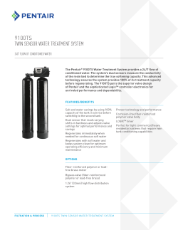


© Copyright 2026