
Document 297997
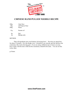
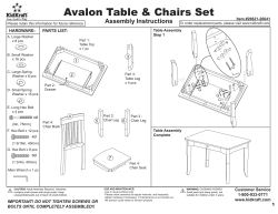
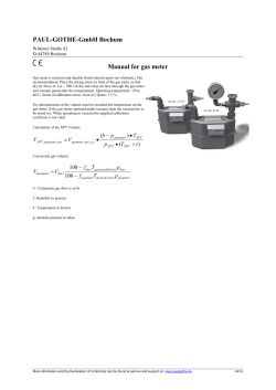
Operator’s Safety and Service Manual
Mortar Mixer
MMH12H390 - 12 Cu. Ft. Hydraulic Mortar Mixer
It is the OWNER´S RESPONSABILITY to communicate information on the
SAFE USE and OPERATION of this machine to the operators.
1
06052014
TABLE OF CONTENTS
Serial Number Location..........................................3
Parts Ordering Procedure......................................3
Operating Instructions...........................................4
Safety Precaution...................................................5
Safety Notice & Decals...........................................6
Safety Decal Locations...........................................7
Before Operating...................................................8
Operation starting engine....................................11
Starting Engine.....................................................12
Service Instructions..............................................13
Maintenance Schedule.........................................14
Replacement........................................................15
Torque Chart........................................................16
Hydraulic Circuit……………………………………………….17
Hydraulic specifications………………………………..…..18
Warranty..............................................................20
Warehouse Locations...........................................21
Notes………………………...........................................22
Parts list.
2
SERIAL NUMBER LOCATION
1. The model/serial number decal is located on the shroud assembly (black).
(Write model number)
(Write serial number)
The unit’s year of manufacture can be determined by the serial number. Contact your nearest
sales branch or
for this information.
BEFORE OPERATING
The warranty is stated in this book on page 16. Failure to return warranty registration card
renders the warranty null and void.
An “owner´s manual” for the engine is also furnished. Engine parts may order from any
authorized dealer. Refer to the engine owner´s manual for exploded views and part
identifications.
PARTS ORDERING:
Parts are available worldwide and must be ordered through your local distributor. If
you can’t locate the
distributor in your area refer to page 17 of this manual to
locate the
branch nearest you and call for assistance.
ALWAYS INCLUDE:
1.
2.
3.
4.
5.
Model and serial number of machine when ordering
parts.
Model and serial number of engine when ordering engine parts.
Item part number(S), description, and quantity.
Company name, address, zip code, and purchase order number.
Preferred method of shipping.
REMEMBER – you own the best. If repairs are needed use
only parts purchased from an authorized distributor.
3
OPERATING INSTRUCTIONS
INTRODUCCION
Mixers are intended for use in very severe applications. They are powered by four
cycle gas engines or electric motors and are available in different sizes and manufacturers.
This parts manual contains only standard parts. Variations of these parts as well as other
special parts are not included. Contact your local
distributor for assistance in
identifying parts not included in this manual.
ASSEMBLY INSTRUCTIONS
1. Remove the mixer and all components from the crate. You should have:
• Two wheels.
• Axle assembly with idler spring, hubs, and lug nuts.
• Hitch with pin and safety bolt.
Note: all installation hardware is inserted into its respective location on the mixer.
2. Lift the mixer up approximately 18” using appropriate lifting equipment.
Warning: failure to use proper lifting equipment could cause
mixer to fall and cause serious injury.
3. Remove the front leg mounting hardware located on the front frame.
4. Position the safety chains through the key slots in the front leg. Adjust the chains ends
to equal lengths.
5. Line up the holes between the leg and the mixer frame. Secure the leg to the frame
using the bolt, washers and nuts that were removed in step 3. Make sure a washer is
located on both sides and the lock washer is against the nut. After all hardware is in
place torque the bolts to 35 ft-lbs.
6. Remove the axle-mounting hardware (six 1/2" bolts) from the rear of the mixer frame.
7. Place the axle on the ground under the mixer and position it with the spring mount to
the left side of the mixer.
8. Lift the axle up to the mixer frame and position it with the vertical mounting brackets
to the inside of the mixer frame. Insert two 1/2 inch bolts with a washer through the
frame and the vertical mounting bracket on the axle. Secure each bolt with a washer
and locknut. Do not tighten at this time.
9. Repeat step 8 for the other side.
4
SAFETY PRECAUTIONS
READ AND STUDY THE FOLLOWING SAFETY INFORMATION BEFORE ATTEMPTING TO OPERATE THIS
EQUIPMENT. IN ADDITION, ENSURE THAT EVERY INDIVIDUAL WHO OPERATES OR WORKS WITH
THIS EQUIPMENT IS FAMILIAR WITH THESE SAFETY PRECAUTIONS.
WARNING - LETHAL EXHAUST GAS!
An internal combustion engine discharges carbon monoxide, which is a poisonous and odorless
invisible gas. Death or serious illness may result if inhaled. Operate only in an area with good
ventilation, NEVER IN A CONFINED AREA!
WARNING - DANGEROUS FUELS!
Use extreme caution when storing, handling and using fuels - they are highly volatile and explosive in
the vapor state. Do not add fuel while engine is running. Stop and cool the engine before adding fuel.
DO NOT SMOKE WHEN REFUELING!
SAFETY GUARDS
It is the owner's responsibility to ensure ALL GUARDS AND SHIELDS are in place and in working order.
IGNITION SYSTEMS
Breakerless magneto and battery ignition systems CAN CAUSE SEVERE ELECTRICAL SHOCKS. Avoid
contacting these units or their wiring.
SAFE DRESS
DO NOT WEAR loose clothing, rings, wristwatches, etc., near machinery.
NOISE PROTECTION
Wear O.S.H.A. specified hearing protection devices.
FOOT PROTECTION
Wear O.S.H.A. specified steel tip safety shoes.
HEAD PROTECTION
Wear O.S.H.A. specified safety helmets.
EYE PROTECTION
Wear O.S.H.A. specified eyes shields, safety glasses, and sweat bands.
DUST PROTECTION
Wear O.S.H.A. specified dust mask or respirator.
OPERATOR
Keep children and bystanders off and away from the equipment.
OPERATOR
For details on safety rules and regulations in the United States, contact your local. Occupational
Safety and Health Administration (O.S.H.A.) office. Equipment operated in other countries must be
operated and serviced in accordance and compliance with any and all safety requirements of that
country. The publication of these safety precautions is done for your information does not by the
publication of these precautions, imply or in any way represent that these are the sum of all dangers
present near
equipment. If you are operating
it is your responsibility to
insure that such operation is in full accordance with all applicable safety requirements and codes. All
requirements of the United States Federal Occupational Safety and Healthy Administration Act must
be met when operated in areas that are under the jurisdiction of that United States Department.
5
SAFETY NOTICE & DECALS
IMPORTANT NOTICE
The "SAFETY ALERT SYMBOL" is used to call attention to items or operations that may be dangerous
to those operating or working with this equipment. These symbols can be found throughout the
manual and on the unit itself. Please read these warnings and cautions carefully.
READ SAFETY DECALS CAREFULLY
Carefully read and follow all safety decals. Keep them in good condition. If they become
damaged, replace as required. If repainting, REPLACE ALL decals. Decals are available from
your authorized
Distributors. Decals are not shown to scale.
201012
201157
201155
201151
6
201150
SAFETY NOTICE & DECALS
IMPORTANT NOTICE
The "SAFETY ALERT SYMBOL" is used to call attention to items or operations that may be dangerous
to those operating or working with this equipment. These symbols can be found throughout the
manual and on the unit itself. Please read these warnings and cautions carefully.
READ SAFETY DECALS CAREFULLY
Carefully read and follow all safety decals. Keep them in good condition. If they become
damaged, replace as required. If repainting, REPLACE ALL decals. Decals are available from
your authorized
Distributors. Decals are not shown to scale.
201005
201005
201003 (x2)
201026
201152
201006
290791
201001 SMALL
201004
201001 BIG
201154
7
10. Secure the axle mount to the mixer frame using the remaining 1/2" bolts, washers, and
locknuts. Make sure a washer is positioned against the axle mount and the frame.
11. Torque all axle hardware to 57 ft-lbs.
12. Remove the lug nuts and install the wheel. Replace the lug nuts and torque to 105 ftlbs.
13. Lower the mixer to the ground.
14. Remove the safety bolt and pin from the tow bar.
15. Install the tow bar through the front leg.
16. Insert the pin through the front leg and the front hole in the tow bar. Secure the pin
with a hairpin cotter.
17. Insert the 3/4" bolt through the rear hole and secure with a lock washer and nut.
Tighten securely.
18. Hook one end of the spring to the idler arm. Hook the other end of the spring to the
spring plate on the axle. The spring should be hooked through the second hole from
the top toward the middle of the mixer.
BEFORE OPERATING
REMEMBER! it is the owner´s responsibility to communicate information on the safe
use and proper operation of this unit to the operators.
Before operating, review SAFETY PRECAUTIONS listed on page 5 of this manual.
Familiarize yourself with the operation of the unit and confirm that all controls
function properly BEFORE starting engine.
Know how to STOP the unit.
Make sure hands, feet, and clothing are at a safe distance from any moveable parts
prior to starting.
Shrouds and grids are provided to protect the operator or structures in close proximity
to rotating hot engine parts. It is the RESPONSABILITY OF THE OPERATOR to see that
they are properly in place.
OIL LEVEL - Check the oil level in the engine. For more information see "Lubrication"
under the engine "Owner's Manual" the "Maintenance" section of this manual.
AIR CLEANER - Check to ensure element is in good condition and properly installed.
Review every decal with the OPERATOR.
8
SAFETY DECAL LOCATION
201001 BIG
9
SAFETY DECAL LOCATION
201001 SMALL
When is electric
10
FUEL SUPPLY - These engines on
Mixer equipment require an automotive grade of
clean, fresh, unleaded or regular gasoline.
FUEL FILTER - Check to ensure element is in good condition... Replace if it is clogged or
damaged.
LUBRICATION POINTS - Make sure all pillow blocks and drum trunnions have been
greased.
PADDLES AND BLADES - Check the paddles and make sure they are adjusted to about
1/16" interference. This is mandatory after installing rubber blades on the paddles.
OPERATION STARTING ENGINE
Prior to starting engine, make sure mixer engagement lever is in the "IDLE" POSITION.
Gas engine
1.
2.
3.
4.
5.
6.
Open the fuel valve.
Pull the stop switch on the engine shroud to its "Out" position.
Move the engine throttle control to the "FAST" position.
Choke the engine if necessary.(You may not need to choke a warm engine)
Pull the starter rope.
After the engine starts, move the choke lever to the open position Move the throttle
level to the "IDLE" position and let the engine warm-up for one or two minutes.
Electric motor
1. Plug the motor into a suitable power source.
2. Move the switch on the motor to the "on" position.
OPERATING
1. If using a gas engine, allow the engine to warm up then move the throttle to the fast
position.
2. Close the engine shroud
DO NOT OPERATE THE MIXER WITH THE SHROUD OPEN!
3. Move the engagement lever to the "MIX “position and charge the mixer.
4. After discharging a batch of mortar, it is recommended to add water for the next
batch.
5. After discharging the final batch of mortar, add water to the drum while the mixer is
running. Discharge the water after the inside of the mixer is clean.
11
STARTING ENGINE
GAS ENGINE
1. Move the engagement lever to the "IDLER" position.
2. Whenever possible it is recommended to let the engine idle before stopping.
3. Push in the engine stop switch on the engine shroud.
4. Close the fuel valve.
ELECTRIC MOTOR
1. Move the switch on the motor to the "off" position.
STOP THE ENGINE OR ELECTRIC MOTOR BEFORE:
Adding fuel.
Leaving equipment unattended for any amount of time.
Making any repairs or adjustments to the unit.
Transporting
TOWING:
1. Stop the engine or electric motor.
2. Close and latch the engine should.
3. Rotate the drum into the tow position and secure the locking pin.
4. Secure the mixer hitch and safety chains to the vehicle.
BEFORE TOWING:
Make sure the axle and tow bar hardware is tight.
Check the condition of the pin on the tow bar and make sure it is secure.
Remove any loose debris from the mixer.
Use safety chains when towing.
MAXIMUM TOW SPEED: 45 mph
12
SERVICE INSTRUCTIONS
Never service or lubricate the unit engine running.
After servicing unit, restore and fasten all guards, shields, and covers to their original
positions.
Never drain oil onto the ground, into open streams, or down sewage drains.
ENGINE
See engine owner´s manual maintenance schedule.
DRUM
1. Wash the drum after each day’s use.
2. Pull the locking pin and tip the drum forward to drain excess water.
3. Return drum to two positions and secure with locking pin before moving mixer.
13
LUBRICATION
1. Grease all fittings daily. All mixers have 6 grease fittings, 4 pillow blocks and 2 drum
trunnions. Two of the fittings are located at each end of the mixer drum on the top of
pillow blocks and trunnions.
The two remaining grease fittings are located under the engine shroud on the top of
the intermediate shaft pillow blocks (see picture below).
2. Electric mixers only: oil the drive chain once a week.
MAINTENANCE SCHEDULE
Maintenance
Engine
Bearings
Refer to engine operator/owner
manual
Grease
V-Belts
Check for excessive wear
Roller chain
Check for excessive wear
Hardware
Tires
Each
use
Every
50 hours
Every
100 hours
Yearly
X
X
X
X
X
X
X
X
X
X
Check and tighten 1,2
Check air pressure
Every
20 hours
X
X
1. Check all hardware after the first 5 hours of use, the follow the maintenance schedule.
2. Retorque the front leg and axle hardware after the first 50 miles traveled, and then
follow the maintenance schedule.
14
REPLACEMENT
Parts
Engine Components
V-Belts
Roller Chain
Gears
Hardware
Safety Decals
Tolerance or Replacement Cycle
Refer to your engine manufacturer´s Owner´s
Manual
Replace if stretched to the point that the idler does
not work properly. Replace the V-belts if they are
cracked or torn.
Replace if there is excessive play between the links
or the links are. Damaged.
Replace if the teeth are cracked or have become
sharp.
Retorque all bolts after the first eight hours of
operation and check Hardware every 25 hours.
Replace any worn or damaged hardware as
needed. Replacement hardware should be grade 5
and zinc plated.
Replace if they become damaged or cannot be
easily read.
15
TORQUE CHART
16
Hydraulic Circuit for “Automatic Dump” Mixer with Two-Spool Control
Valves for Alternate Operation Design
The main beam of the mixer was designed as a
hydraulic reservoir. The tank was sized to adequately
cool the oil sufficiently, and provide tie to deaerate
the oil, all without requiring the use of other heat
exchangers or cooling fans.
CAUTION: Breather cap is under pressure. Remove
breather cap only when cool enough to touch with
bare hands. Slowly loosen cap to relieve pressure
before removing completely.
The reservoir is equipped with a pressurized
breather filter 91) that reduces the out en inflow of
air due to thermal expansion and contraction of the
hydraulic oil. This substantially reduces the amount
of contaminants that can enter the reservoir.
To remove the breather cap-use a wrench on the
hexagonal portion of the cap assembly which is
located underneath the main body of the cap.
The pump (3) that is directly coupled to the engine
(4) directs the hydraulic fluid to a double-spool
directional control valve assembly (5). This valve
assembly, with an internal pressure relief, set at
2100 psi (14.47 Mpa) controls both the paddle shaft
motor (6) and the mix dumping cylinder (7). The mix
dumping control valve is a 4-way, 3-position valve
that is self-centering, springs return the spool to
center neutral position. The paddle shaft motor
control valve is also a 4-way, 3-position valve that is
detented (locked) in the mixing mode, and selfcentering in the reserve mode. This allows the
paddle shaft to rotate in a counter-clockwise
direction (mixing direction) without having to
maintain a hand on the control lever. The hydraulic
flud returns to the reservoir via a conveniently
located (for service) oil filter (8) with a 25 psi (0.17
Mpa) bypass.
17
1.
2.
3.
4.
5.
Pressurized Breather Filter
Oil Strainer
Gear Pump
Engine
Directional Control Valve assembly with
2100 psi (14.47 Mpa) pressure relief
6. Paddle Shaft Motor
7. Mix Dumping Cylinder
8. Spin-on Filter with 5 psi (0.17 Mpa)
bypass
HYDRAULIC MORTAR MIXER ESPECIFICATIONS
THE POWER UNIT
This hydraulic system, powered by a 13 Honda gas engine, operating at 3400-3500 rmp, has been designed to
develop more than 5100 inch pounds of torque and turn the paddle shaft at 33-34 rpm. The dump cycle is set
for maximum speed of 5.5 seconds.
THE PUMP
The hydraulic system should be adjusted to operate at 2100 psi. This high-strength extruded aluminum pump
with bushing block pressure plates offers more performance and strength than the more economical “Die cast
aluminum pumps. To achieve the longest possible life for both the engine and pump, the pump is mounted
directly to the engine which assures the correct alignment whit the paddle shaft…this is critical.
SPECIAL NOTE: All settings on the hydraulic system are factory preset…field adjustments may void the
warranty.
THE VALVES
The directional valves are high-performance. These newly designed valves offer low internal leakage which
means more oil goes to the system for work and less heat is generated. An integral relief valve protects the
hydraulic system from high pressure shock loading and excessive system pressure…relieving the oil to the tank.
THE HYDRAULIC MOTOR
The hydraulic motor is a disc valve design as opposed to a motor shaft/spool design. This motor offers the
highest performance with the least internal fluid loss. This disc valve design motor offers a higher bearing load
capability than most competitive units… this means longer life for the hydraulic motor.
The correct operating fluid level is when the “LUBE-sight” plug is ¾ full.
THE TANK FRAME
Allowing for heated-fluid expansion, this tank holds 14.6 gallons of hydraulic oil. A “LUBE-sight” plug has been
mounted on the tank so that fluid levels can be monitored.
THE PRESSURIZED BREATHER/FILLER CAP:
Maintains a 5 psi positive head pressure on oil in the tank - keeping the air exchange and ingestion of concrete
dust in to the hydraulic system at a minimum.
The blanket pressure of 5 pas also assists in priming the hydraulic pump forcing fluid from tank to pump inlet.
OTHER SPECIALS
1.
2.
3.
4.
5.
All hydraulic fluid is filtered as it is returned to the tank.
Heavy – duty “chain style” sprocket increases the torque transfer.
Pressure connections are sae o-ring boss style fittings.
Hose connections are JIC style flare with swivels.
Low pressure connections are NPT with sur -lok pipe sealant.
18
HYDRAULIC MORTAR MIXER
ESPECIFICATIONS
1. Heavy Duty safety duty grade with built in bag cutter.
2. Durable paddle shaft of 1 3/4" square hardened steel. Double sealed
bearings with eight spring loaded greaseable shaft seals.
3. Heavy-duty removable tow. Tongue made of though schedule 80 steel.
4. Solid 1 5/8" axle with large 878x13" tires for smooth towing. Suspension
springs standard less bounce, less sway.
5. Rugged 14 gauge steel engine cover with punches pressed ventilation
openings for increased cooling and added strenght.
6. Dual controls-mixing blades and optional hydraulic pump.
MODEL
Batch Capacity bags
Batch capacity cu. ft. (lts)
Power Sources
Average weight - lbs (kgs)
Lenght with tongue x W x H - in (cms)
Height not including handle - in (cms)
Discharge height - in (cms)
Drive
Dump action
HM20
HM160
3 1/2 - 4
4 1/2 - 5 1/2
12 (340)
16 (450)
5HP 1 230/460V Electric
5HP 1 230/460V Electric
5HP 2 230/460V Electric
5HP 2 230/460V Electric
13HP Honda
13HP Honda
1430 (650)
1529 (695)
99 x 55 x 66 (251 x 139 x 167)
102 x 55 x 66 (259 x 139 x 167)
66 (167)
66 (167)
23 (58)
23 (58)
Hydraulic
Hydraulic
Manual (Optional Hydraulic dump)
Hydraulic Dump
Mixer weight shown is an average; exact weight is dependent upon power source.
Dual controls-mixing blades and
optional hydraulic pump.
19
WARRANTY
THIS IS YOUR WARRANTY - PLEASE READ AND SAVE
1.
Warrants each new machine against defects in material and workmanship
under normal use and service for a period of six (6) months. This warranty commences
the first day the machine is sold, assigned to a rental fleet, or otherwise put to its first
use.
2. The obligation under this warranty is limited to the replacement of parts at your
factory branch or an authorized
Distributor.
3. Machines altered or modified without
written consents voids this warranty.
Misuse, negligence, accidents or the operation of machines in any way other than
recommended by
will void this warranty. This warranty shall not apply to
machines repaired by other than
factory branches or authorized
Distributors.
4. The cost of transportation and other expenses connected therewith are not covered
by this warranty.
5. Written authorization for the return of merchandise under warranty must be obtained
from
.
6.
Reserves the right to inspect and render the final decision on each warranty
case.
7.
Reserves the right to improve or make product changes without incurring any
obligation to update, refit, or install the same on machines previously sold.
8.
Is not responsible for any liability or damage or injury directly or indirectly
from the design, material or operation of its products.
9. The warranty card must be returned to
within 10 days after purchase,
assignment to a rental fleet, or first use. Failure to return the warranty card as
specified renders the warranty null and void.
10. Requests for warranty must be submitted in writing within 30 days after machine
failure to
.
11. THE FOREGOING WARRANTY IS EXPRESSLY IN LIEU OF ALL OTHER WARRANTIES,
FITNESS FOR USE, AND OF ALL OTHER OBLIGATIONS OR LIABILITIES ON OUR PART,
AND WE NEITHER ASSUME NOR AUTHORIZE ANY OTHER PERSON TO ASSUME FOR US
ANY OF OUR PRODUCTS. LIKEWISE, THIS WARRANTY SHALL NOT APPLY WITH RESPECT
TO ENGINES, MOTORS, AND THEIR COMPONENTS.
20
WAREHOUSE LOCATIONS
Is at your service
has established a network of reputable distributors with trained mechanics and full
facilities for maintenance and rebuilding, and to carry an adequate parts stock in all areas of
the country. Their sales engineers are available for professional consultation. If you cannot
locate your
distributor contact our sales branch listed below.
REMEMBER - you own the best. If repairs are need use only
from your authorized distributor.
Dan Wagner
Operations Manager, Bartell Morrison USA
_____________________________________________
Office: +1-732-566-5400
Direct : +1-732-812-3126
Fax: +1-732-566-5444
Email: [email protected]
Jeff Durgin
President, Bartell Morrison USA, LLC
Office: +1-732-566-5400
Mobile: +1-732-241-8427
Fax: +1-732-566-5444
Email: [email protected]
21
parts purchased
NOTES:
_________________________________________________
_________________________________________________
_________________________________________________
_________________________________________________
_________________________________________________
_________________________________________________
_________________________________________________
_________________________________________________
_________________________________________________
_________________________________________________
_________________________________________________
_________________________________________________
_________________________________________________
_________________________________________________
_________________________________________________
_________________________________________________
_________________________________________________
_________________________________________________
_________________________________________________
_________________________________________________
_________________________________________________
22
REV022013
REPAIR PARTS MANUAL / MANUAL DE PARTES
HYDRAULIC MIXER 12HM
23
DRUM ASSEMBLY / ENSAMBLE TANQUE
No. Part Num. Número de Parte Description
1
2
3
4
5
6
7
8
9
10
11
12
13
14
15
16
17
18
19
20
21
T700
T701
T115
T173-2
T702
T703
T704
T705
T706
T175
T177
T174
T114
T105
T110
T172
T101
T104
T106
T189
T102
0200SO01RJ
0200CO01TN
0200KI02TN
SM00300INT
TOCL038112
TCCS038GAL
RNPX012GAL
SR00036EXT
0200KI01TN
00CHPI2300
TOCD012212
TCCS012GAL
TOCD012134
0000GRH045
Drum, HM12
Grid, HM12
Handle Grid
Trunnion
Hyd, Trunnion
Red Rubber
Flat Washer, 1/8 x 3
Black Rubber
Steel Seal C-29
Ball Bearing 208-24
Retaining Ring 3" External
Carriage Bolt, 3/8 x 1-1/2
Lock Nut, 3/8
Flat Washer, 1/2 SAE
Pin, Hair 3/16
Kit, Rubber Seal
Pillow Block, 3"
Hex Head Bolt, 1/2 x 2-1/2
Lock Nut, 1/2
Hex Head Bolt, 1/2 x 1-3/4
Fitting, Grease 45 Deg.
24
Descripción
Tanque HM12
Rejilla HM12
Palanca Rejilla
Trunnion
Trunnion Hidraulico
Hule Rojo
Rondana Plana, 1/8 x 3
Hule Negro
Lamina Acero
Balero 208-24
Seguro Omega 3" Exterior
Tornillo Cabeza Coche 3/8 x 1-1/2
Tuerca de Seguridad 3/8
Rondana Plana, 1/2 SAE
Seguro R, 3/16
Kit, Empaques de Hule
Chumacera Tanque 3" PI
Tornillo Hex 1/2 x 2-1/2
Tuerca de Seguridad 1/2
Tornillo Hex 1/2 x 1-3/4
Grasera, 45 grados
Qty/Cant.
1
1
1
1
1
2
6
4
2
2
2
8
8
13
3
2
2
4
5
1
2
PADDLE ASSEMBLY / ENSAMBLE ASPAS
7
10
15
16
9
8
17
15
16
15
5
16
15
8
7
2
6
15
14
15
14
11
12
1
3
6
12
13
No. Part Num. Número de Parte
1
2
3
4
5
6
7
8
9
10
11
12
13
14
15
16
17
T741
T306
T308
T314
T309
T188
T307
T181
T310
T311
T189
T105
T106
T176
T112
T114
T145
0205CC01CH
0200CO01AS
0200CO02AS
0200CO03AS
0200CO04AS
0200SO05AS
0200RF01AS
0200SO01AS
0200RF02AS
0200SO02AS
TOCD012134
RNPX012GAL
TCCS012GAL
TOCD038112
RNPX038GAL
TCCS038GAL
TOCD038200
Description
Main Shaft, HM12
Paddle, Middle right
Paddle, Middle Left
Paddle, Right Arm
Paddle, Left Arm
Paddle Arm Bracket
Rubber, Center Blade
Center Blade
Rubber, Side Blade
Side Blade
Hex Head Bolt, 1/2 x 1-3/4
Flat Washer, 1/2 SAE
Lock Nut, 1/2
Hex Head Bolt, 3/8 x 1-1/2
Flat Washer, 3/8 SAE
Lock Nut, 3/8
Hex Head Bolt, 3/8 x 2
25
Descripción
Flecha Central HM12
Aspa Central Derecha
Aspa Central Izquierda
Aspa Lateral Derecha
Aspa Lateral Izquierda
Abrasadera
Hule Central
Contra Aspa Central
Hule Lateral
Contra Aspa Lateral
Tornillo Hex 1/2 x 1-3/4
Rondana Plana, 1/2 SAE
Tuerca de Seguridad 1/2
Tornillo Hex 3/8 x 1-1/2
Rondana Plana, 3/8 SAE
Tuerca de Seguridad 3/8
Tornillo Hex 3/8 x 2
4
Qty/Cant.
1
1
1
1
1
2
4
4
2
2
6
12
6
18
40
20
2
SPIRAL ASSEMBLY / ENSAMBLE DE ASPAS
15
40
18
36
13
1
12
11
36
No. Part Num.Número de Parte Description
1
11
12
13
18
15
36
40
T741
T189
T105
T106
T742
T112
T176
T114
0205CC01CH
TOCD012134
RNPX012GAL
TCCS012GAL
RNPX038GAL
TOCD038112
TCCS038GAL
Main Shaft, HM12
Hex Head Bolt, 1/2 x 1-3/4
Flat Washer, 1/2 SAE
Lock Nut, 1/2
Spiral Aseembly, HM12
FLat Washer, 3/8 SAE
Hex Head Bolt, 3/8 x 1-1/2
Lock nut, 3/8
26
Descripción
Flecha Central HM12
Tornillo Hex 1/2 x 1-3/4
Rondana Plana, 1/2 SAE
Tuerca de Seguridad 1/2
Ensamble Espiral, HM12
Ensamble Espiral, HM12
Ensamble Espiral, HM12
Tuerca de Seguridad 3/8
Qty/Cant.
1
6
12
6
1
32
16
16
FRAME ASSEMBLY / ENSAMBLE CHASIS
39
38
21
34
41
38
40
20
43
19
18
17
52
46
45
29
45
44
51
23
22
24
25
38
37
36
41
38
42
37
36
35
26
27
28
47
35
32
34
33
30
31
32
4
54
6
16
6
50
49
1
47
5
13
11
12
14
15
9
10
9
8
48
2
27
3
No. Part Num. Número de Parte
1
2
3
4
5
6
8
9
10
11
12
13
14
15
16
17
18
19
20
21
22
23
24
25
26
27
28
29
30
31
32
33
34
35
36
37
38
39
40
41
42
43
44
45
46
47
48
49
50
51
52
53
54
T707
T118
T121
T708
T709
T710
T130
T131
T141
T132
T134
T135
T136
T137
T129
T712
T713
T714
T715
T716
T717
T718
T719
T720
T721
T722
T723
T724
T725
T726
T105
T727
T189
T728
T176
T729
T112
T145
T114
T730
T731
T732
T733
T734
T735
T736
T737
T738
T739
T740
T760
T800
T104
0200CO01LZ
0200CR01LZ
0000RF01RD
0000RF02RD
0000RF08RD
0000RF03RD
0000RF05RD
SC18112NOR
0000RF06RD
0000CO01RD
0200KI01RD
RNPX012GAL
TOCD012134
TOCD038112
RNPX038GAL
TOCD038200
TCCS038GAL
OPCR516516
TOCD516134
TOCD012212
Description
Main Frame, HM12
Pintle Hitch
Lock Pin
Axle Bracket
Axle HM
"U" Clamp
Seal, grease
Bearing, 6205
Rim Hub
Plain Washer,1/8 x 3/4 x 1-1/4
Nut, Castle 3/4
Pin, Cotter 1/8 x 1-1/2
Cover, Dust
Wheel and Tire
Hub, 4 bolt, Assy
Sprocket
Chain
Pump Sprocket
Hydraulic Motor
Engine,
Coupler, 3/4"
Insert
Adaptor Pump/Motor
Hydraulic Pump
Hex Head Bolt, 1" x 3-1/2"
Cylinder
Pin, Cylinder
Valve, 2 Spool Press Comp
Filter Coupler
Oil Filter
Flat Washer, 1/2 SAE
Nut, 1/2 NF
Hex Head Bolt, 1/2 x 1-3/4
Lock Nut, 1/2
Hex Head Bolt, 3/8 x 1-1/2
Lock Washer, 3/8
Flat Washer, 3/8 SAE
Hex Head Bolt, 3/8 x 2
Lock Nut, 3/8
Set Screw, 5/16 x 5/16
Key, 1/2 x 2
Key, 1/4 x 2
Hex Head Bolt, 5/16 x 1-3/4
Flat Washer, 5/16
Lock Nut, 5/16
Hex Head Bolt, 3/4 x 3-1/2 NF
Lock Washer, 3/4
Nut, 3/4 NF
Coupler, 1"
Reflective
Spring
Hex Head Bolt, 1/2 x 2-1/2
28
Descripción
Chasis HM12
Lanza Militar
Perno Lanza
Soporte para Eje
Eje HM
Abrazadera U
Reten
Balero 6205
Masa Rim
Rondana Plana 1/8 x 3/4 x 1-1/4
Tuerca Castillo 3/4
Chaveta 1/8 x 1-1/2
Cubre Polvo Masa Rim
Llanta y Rim
Ensamble Masa Rim
Catarina Flecha Central
Cadena de Transmisión
Catarina para Bomba
Motor Hidraulico
Motor
Muela, 3/4"
Cople para Muela
Montaje de Bomba hidraulica
Bomba Hidraulica
Tornillo 1" x 3-1/2"
Gato Hidraulico
Perno Gato Hidraulico
Válvula Hidraulica
Adaptador para Filtro
Filtro de Aceite
Rondana Plana 1/2 SAE
Tuerca 1/2 NF
Tornillo Hex 1/2 x 1-3/4
Tuerca de Seguridad 1/2
Tornillo Hex 3/8 x 1-1/2
Rondana Presión 3/8
Rondana Plana 3/8 SAE
Tornillo Hex 3/8 x 2
Tuerca de Seguridad 3/8
Opresor, 5/16 x 5/16
Cuña, 1/2 x 2
Cuña, 1/4 x 2
Tornillo Hex 5/16 x 1-3/4
Rondana Plana 5/16
Tuerca de Seguridad 5/16
Seguro R, 3/16
Tornillo Hex 3/4 x 3-1/2 NF
Rondana Presión 3/4
Tuerca 3/4 NF
Muela, 1"
Reflejantes
Muey
Tornillo de 1/2 x 2-1/2
Qty/Cant.
1
1
1
2
1
2
2
2
2
2
2
2
2
2
2
1
1
1
1
1
2
1
1
1
1
1
1
1
1
1
16
4
10
12
8
8
16
4
4
4
1
1
2
4
2
3
1
1
1
1
2
2
2
HOOD ASSEMBLY / ENSAMBLE GABINETE
5
10
9
7
8
7
6
4
3
6
7
8
7
9
2
1
11
No. Part Num. Número de Parte
1
2
3
4
5
6
7
8
9
10
11
T743
T116
T195
T170
T158
T744
T745
T746
T114
T159
T800
0000RF02GA
0000RF04GA
0200RF01GB
0000RF01GA
TOCD038114
RNPX038ESP
RNPX012ESP
TCCS038GAL
TCCS014GAL
Description
Descripción
HM Hood
Gabinete HM
Hook
Seguro Cofre
Switch
Push Stop
Electric Harness
Arnes Eléctrico
Rubber Screw
Regaton
Hex Head Bolt, 3/8 x 1-1/4 Tornillo Hex 3/8 x 1-1/4
Flat Washer Sp. 3/8
Rondana Plana Esp. 3/8
Flat Washer Sp. 1/2
Rondana Plana Esp. 1/2
Lock Nut, 3/8
Tuerca de Seguridad 3/8
Lock Nut, 1/4
Tuerca de Seguridad 1/4
Support
Soporte gabinete
29
Qty/Cant.
1
1
1
1
3
6
12
6
6
3
2
HYDRAULIC SCHEMATIC / ESQUEMA HIDRÁULICO
30
Prt No.
Description / Descripción
Location
Ubicación
Qty
T747
Hose, 1/2 x 29", 1/2 NPT ~ 1/2 NPT / Manguera, 1/2 x 29", 1/2 NPT ~ 1/2 NPT
Oil Tank to Hyd Pump Tanque a Bomba Hid.
T748
Hose, 1/2 x 20", 1/2 NPT ~ 1/2 NPT / Manguera, 1/2 x 20", 1/2 NPT ~ 1/2 NPT
Hyd Pump to Valve
Bomba Hid. A Válvula
1
T749
Hose, 1/2 x 24", 1/2 NPT ~ 1/2 NPT / Manguera, 1/2 x 24", 1/2 NPT ~ 1/2 NPT
Valve to Hyd Motor
Válvula a Motor Hid.
2
T750
Hose, 1/2 x 52", 1/2 NPT ~ 1/2 NPT / Manguera, 1/2 x 52", 1/2 NPT ~ 1/2 NPT
Valve to Cylinder
Válvula a Pistón
2
T751
Hose, 1/2 x 10", 1/2 NPT ~ 1/2 NPT / Manguera, 1/2 x 10", 1/2 NPT ~ 1/2 NPT
Valve to Filter
Válvula a Filtro
1
T752
Elbow , 1/2 NPT ~ 1/2 NPT / Codo, 1/2 NPT ~ 1/2 NPT
Cylinder
Pistón
1
T753
Elbow , 5/8 NPT ~ 1/2 NPT / Codo, 5/8 NPT ~ 1/2 NPT
Hyd Motor
Motor Hidraulico
2
T754
Elbow , Long, 1/2 NPT ~ 1/2 NPT / Codo largo, 1/2 NPT ~ 1/2 NPT
Hyd Pump
Bomba Hidraulica
1
T753
Elbow , 5/8 NPT ~ 1/2 NPT / Codo, 5/8 NPT ~ 1/2 NPT
Hyd Pump
Bomba Hidraulica
1
T755
Cap, 1/2 / Tapon, 1/2
Valve
Válvula
2
T752
Elbow , 1/2 NPT ~ 1/2 NPT / Codo, 1/2 NPT ~ 1/2 NPT
Valve
Válvula
4
T756
Elbow , Long, 1/2 NPT ~ 1/2 NPT / Codo largo, 1/2 NPT ~ 1/2 NPT
Valve
Válvula
2
T757
Collector Reducer Coupling, 1/2 NPT ~ 3/4 Male / Cople Colector Reductor, 1/2 NPT ~ 3/4 Macho Filter
Filtro
1
T758
Elbow , 3/4 Female ~ 3/4 Male / Codo, 3/4 Hembra ~ 3/4 Macho
Filter
Filtro
1
T759
Niple, 3/4 NPT
Filter
Filtro
1
HYDRAULIC HOSES & FITTINGS / MANGUERAS HIDRÁULICAS Y CONEXIONES
31
1


© Copyright 2026