
SYSMAC C1000HF Programmable Controller Operation Manual Revised May 2003
SYSMAC C1000HF Programmable Controller Operation Manual Revised May 2003 Notice: OMRON products are manufactured for use according to proper procedures by a qualified operator and only for the purposes described in this manual. The following conventions are used to indicate and classify precautions in this manual. Always heed the information provided with them. Failure to heed precautions can result in injury to people or damage to property. DANGER Indicates an imminently hazardous situation which, if not avoided, will result in death or serious injury. ! WARNING Indicates a potentially hazardous situation which, if not avoided, could result in death or serious injury. ! Caution Indicates a potentially hazardous situation which, if not avoided, may result in minor or moderate injury, or property damage. ! OMRON Product References All OMRON products are capitalized in this manual. The word “Unit” is also capitalized when it refers to an OMRON product, regardless of whether or not it appears in the proper name of the product. The abbreviation “PC” means Programmable Controller and is not used as an abbreviation for anything else. OMRON, 1989 All rights reserved. No part of this publication may be reproduced, stored in a retrieval system, or transmitted, in any form, or by any means, mechanical, electronic, photocopying, recording, or otherwise, without the prior written permission of OMRON. No patent liability is assumed with respect to the use of the information contained herein. Moreover, because OMRON is constantly striving to improve its high-quality products, the information contained in this manual is subject to change without notice. Every precaution has been taken in the preparation of this manual. Nevertheless, OMRON assumes no responsibility for errors or omissions. Neither is any liability assumed for damages resulting from the use of the information contained in this publication. v TABLE OF CONTENTS PRECAUTIONS . . . . . . . . . . . . . . . . . . . . . . . . . . . . . . . . . 1 Intended Audience . . . . . . . . . . . . . . . . . . . . . . . . . . . . . . . . . . . . . . . . . . . . . . . . . . . . . . . . . . . 2 General Precautions . . . . . . . . . . . . . . . . . . . . . . . . . . . . . . . . . . . . . . . . . . . . . . . . . . . . . . . . . . 3 Safety Precautions . . . . . . . . . . . . . . . . . . . . . . . . . . . . . . . . . . . . . . . . . . . . . . . . . . . . . . . . . . . 4 Operating Environment Precautions . . . . . . . . . . . . . . . . . . . . . . . . . . . . . . . . . . . . . . . . . . . . . 5 Application Precautions . . . . . . . . . . . . . . . . . . . . . . . . . . . . . . . . . . . . . . . . . . . . . . . . . . . . . . SECTION 1 Introduction . . . . . . . . . . . . . . . . . . . . . . . . . . . . . . . . . . . . 1-1 1-2 1-3 1-4 Flowchart Programming . . . . . . . . . . . . . . . . . . . . . . . . . . . . . . . . . . . . . . . . . . . . . . . . . . . 1-1-1 Sequential Control . . . . . . . . . . . . . . . . . . . . . . . . . . . . . . . . . . . . . . . . . . . . . . . . 1-1-2 Branched Control . . . . . . . . . . . . . . . . . . . . . . . . . . . . . . . . . . . . . . . . . . . . . . . . . 1-1-3 Parallel Group Control . . . . . . . . . . . . . . . . . . . . . . . . . . . . . . . . . . . . . . . . . . . . . Elementary Programming Steps . . . . . . . . . . . . . . . . . . . . . . . . . . . . . . . . . . . . . . . . . . . . . 1-2-1 Assessing the Control Task . . . . . . . . . . . . . . . . . . . . . . . . . . . . . . . . . . . . . . . . . 1-2-2 Drawing the Flowchart . . . . . . . . . . . . . . . . . . . . . . . . . . . . . . . . . . . . . . . . . . . . 1-2-3 Converting into Mnemonic Code . . . . . . . . . . . . . . . . . . . . . . . . . . . . . . . . . . . . Elementary Instructions . . . . . . . . . . . . . . . . . . . . . . . . . . . . . . . . . . . . . . . . . . . . . . . . . . . Programming Examples . . . . . . . . . . . . . . . . . . . . . . . . . . . . . . . . . . . . . . . . . . . . . . . . . . . 1-4-1 Example 1: WAIT vs CJP/JMP Instructions . . . . . . . . . . . . . . . . . . . . . . . . . . . . 1-4-2 Example 2: WAIT vs Group Instructions . . . . . . . . . . . . . . . . . . . . . . . . . . . . . . 1-4-3 Example 3: Timing with Group Instructions . . . . . . . . . . . . . . . . . . . . . . . . . . . . 1-4-4 Example 4: Time-Specific Execution . . . . . . . . . . . . . . . . . . . . . . . . . . . . . . . . . 1-4-5 Example 5: Timers and Execution Timing . . . . . . . . . . . . . . . . . . . . . . . . . . . . . SECTION 2 Using the Programming Console . . . . . . . . . . . . . . . . . . . 2-1 2-2 2-3 The Programming Console . . . . . . . . . . . . . . . . . . . . . . . . . . . . . . . . . . . . . . . . . . . . . . . . 2-1-1 The Keyboard . . . . . . . . . . . . . . . . . . . . . . . . . . . . . . . . . . . . . . . . . . . . . . . . . . . . 2-1-2 The Mode Switch . . . . . . . . . . . . . . . . . . . . . . . . . . . . . . . . . . . . . . . . . . . . . . . . . 2-1-3 The Display Message Switch . . . . . . . . . . . . . . . . . . . . . . . . . . . . . . . . . . . . . . . . Preparation for Programming . . . . . . . . . . . . . . . . . . . . . . . . . . . . . . . . . . . . . . . . . . . . . . . 2-2-1 Entering the Password . . . . . . . . . . . . . . . . . . . . . . . . . . . . . . . . . . . . . . . . . . . . . 2-2-2 Clearing Memory . . . . . . . . . . . . . . . . . . . . . . . . . . . . . . . . . . . . . . . . . . . . . . . . . 2-2-3 Setting and Canceling Expanded DM Area . . . . . . . . . . . . . . . . . . . . . . . . . . . . . 2-2-4 Registering the I/O Table . . . . . . . . . . . . . . . . . . . . . . . . . . . . . . . . . . . . . . . . . . . 2-2-5 Reading Error Messages . . . . . . . . . . . . . . . . . . . . . . . . . . . . . . . . . . . . . . . . . . . 2-2-6 Verifying the I/O Table . . . . . . . . . . . . . . . . . . . . . . . . . . . . . . . . . . . . . . . . . . . . 2-2-7 Reading the I/O Table . . . . . . . . . . . . . . . . . . . . . . . . . . . . . . . . . . . . . . . . . . . . . 2-2-8 Changing the I/O Table . . . . . . . . . . . . . . . . . . . . . . . . . . . . . . . . . . . . . . . . . . . . 2-2-9 Transferring the I/O Table . . . . . . . . . . . . . . . . . . . . . . . . . . . . . . . . . . . . . . . . . . Programming Operations . . . . . . . . . . . . . . . . . . . . . . . . . . . . . . . . . . . . . . . . . . . . . . . . . . 2-3-1 Setting a Program Address . . . . . . . . . . . . . . . . . . . . . . . . . . . . . . . . . . . . . . . . . . 2-3-2 Program Write . . . . . . . . . . . . . . . . . . . . . . . . . . . . . . . . . . . . . . . . . . . . . . . . . . . 2-3-3 Program Read . . . . . . . . . . . . . . . . . . . . . . . . . . . . . . . . . . . . . . . . . . . . . . . . . . . . 2-3-4 Instruction Search . . . . . . . . . . . . . . . . . . . . . . . . . . . . . . . . . . . . . . . . . . . . . . . . 2-3-5 Instruction Insert . . . . . . . . . . . . . . . . . . . . . . . . . . . . . . . . . . . . . . . . . . . . . . . . . 2-3-6 Instruction Delete . . . . . . . . . . . . . . . . . . . . . . . . . . . . . . . . . . . . . . . . . . . . . . . . . 2-3-7 Program Check . . . . . . . . . . . . . . . . . . . . . . . . . . . . . . . . . . . . . . . . . . . . . . . . . . . 2-3-8 Program Size Read . . . . . . . . . . . . . . . . . . . . . . . . . . . . . . . . . . . . . . . . . . . . . . . . xv xvi xvi xvi xvi xvii 1 1 1 2 3 5 5 6 7 7 8 9 13 18 20 22 24 24 24 26 27 28 28 29 30 31 33 34 35 38 40 41 41 41 46 48 50 51 52 54 vii TABLE OF CONTENTS 2-4 2-5 2-6 2-7 Monitor and Data Change Operations . . . . . . . . . . . . . . . . . . . . . . . . . . . . . . . . . . . . . . . . 2-4-1 Force Set/Reset . . . . . . . . . . . . . . . . . . . . . . . . . . . . . . . . . . . . . . . . . . . . . . . . . . 2-4-2 Channel Data Changes . . . . . . . . . . . . . . . . . . . . . . . . . . . . . . . . . . . . . . . . . . . . . 2-4-3 Single Channel Operations in Binary . . . . . . . . . . . . . . . . . . . . . . . . . . . . . . . . . 2-4-4 Three-Channel Operations . . . . . . . . . . . . . . . . . . . . . . . . . . . . . . . . . . . . . . . . . . 2-4-5 Group Monitor . . . . . . . . . . . . . . . . . . . . . . . . . . . . . . . . . . . . . . . . . . . . . . . . . . . Debugging . . . . . . . . . . . . . . . . . . . . . . . . . . . . . . . . . . . . . . . . . . . . . . . . . . . . . . . . . . . . . 2-5-1 Step Execution . . . . . . . . . . . . . . . . . . . . . . . . . . . . . . . . . . . . . . . . . . . . . . . . . . . 2-5-2 Section Execution . . . . . . . . . . . . . . . . . . . . . . . . . . . . . . . . . . . . . . . . . . . . . . . . 2-5-3 Step Trace . . . . . . . . . . . . . . . . . . . . . . . . . . . . . . . . . . . . . . . . . . . . . . . . . . . . . . File Memory Operations . . . . . . . . . . . . . . . . . . . . . . . . . . . . . . . . . . . . . . . . . . . . . . . . . . 2-6-1 File Memory Clear . . . . . . . . . . . . . . . . . . . . . . . . . . . . . . . . . . . . . . . . . . . . . . . . 2-6-2 File Memory Write . . . . . . . . . . . . . . . . . . . . . . . . . . . . . . . . . . . . . . . . . . . . . . . . 2-6-3 File Memory Verify . . . . . . . . . . . . . . . . . . . . . . . . . . . . . . . . . . . . . . . . . . . . . . . 2-6-4 File Memory Read . . . . . . . . . . . . . . . . . . . . . . . . . . . . . . . . . . . . . . . . . . . . . . . . 2-6-5 File Memory Read/Write . . . . . . . . . . . . . . . . . . . . . . . . . . . . . . . . . . . . . . . . . . . 2-6-6 File Memory Index Read . . . . . . . . . . . . . . . . . . . . . . . . . . . . . . . . . . . . . . . . . . . Cassette Tape Operations . . . . . . . . . . . . . . . . . . . . . . . . . . . . . . . . . . . . . . . . . . . . . . . . . . 2-7-1 Saving a Program to Tape . . . . . . . . . . . . . . . . . . . . . . . . . . . . . . . . . . . . . . . . . . 2-7-2 Restoring Program Data . . . . . . . . . . . . . . . . . . . . . . . . . . . . . . . . . . . . . . . . . . . . 2-7-3 Verifying Program Data . . . . . . . . . . . . . . . . . . . . . . . . . . . . . . . . . . . . . . . . . . . . 2-7-4 DM<–> Cassette Tape: Save, Restore, and Verify . . . . . . . . . . . . . . . . . . . . . . . SECTION 3 Data and Memory Areas . . . . . . . . . . . . . . . . . . . . . . . . . . 3-1 3-2 3-3 Overview . . . . . . . . . . . . . . . . . . . . . . . . . . . . . . . . . . . . . . . . . . . . . . . . . . . . . . . . . . . . . . I/O and Internal Relay Area - IR . . . . . . . . . . . . . . . . . . . . . . . . . . . . . . . . . . . . . . . . . . . . Special Relay Area SR . . . . . . . . . . . . . . . . . . . . . . . . . . . . . . . . . . . . . . . . . . . . . . . . . . . . 3-3-1 Group Continue Control Bit . . . . . . . . . . . . . . . . . . . . . . . . . . . . . . . . . . . . . . . . 3-3-2 Data Retention Control Bit . . . . . . . . . . . . . . . . . . . . . . . . . . . . . . . . . . . . . . . . . 3-3-3 Output OFF Bit . . . . . . . . . . . . . . . . . . . . . . . . . . . . . . . . . . . . . . . . . . . . . . . . . . 3-3-4 FAL Error Code Output Area . . . . . . . . . . . . . . . . . . . . . . . . . . . . . . . . . . . . . . . 3-3-5 Battery Alarm Flag . . . . . . . . . . . . . . . . . . . . . . . . . . . . . . . . . . . . . . . . . . . . . . . 3-3-6 Indirect Jump Error Flag . . . . . . . . . . . . . . . . . . . . . . . . . . . . . . . . . . . . . . . . . . . 3-3-7 I/O Verification Error Flag . . . . . . . . . . . . . . . . . . . . . . . . . . . . . . . . . . . . . . . . . . 3-3-8 DM Address Error Flag . . . . . . . . . . . . . . . . . . . . . . . . . . . . . . . . . . . . . . . . . . . . 3-3-9 Instruction Execution Error Flag, ER . . . . . . . . . . . . . . . . . . . . . . . . . . . . . . . . . 3-3-10 Arithmetic Operation Flags . . . . . . . . . . . . . . . . . . . . . . . . . . . . . . . . . . . . . . . . . 3-3-11 Clock Bits . . . . . . . . . . . . . . . . . . . . . . . . . . . . . . . . . . . . . . . . . . . . . . . . . . . . . . . 3-3-12 Special I/O Flags and Control Bits . . . . . . . . . . . . . . . . . . . . . . . . . . . . . . . . . . . 3-4 Holding Relay Area - HR . . . . . . . . . . . . . . . . . . . . . . . . . . . . . . . . . . . . . . . . . . . . . . . . . . 3-5 Auxiliary Relay Area - AR . . . . . . . . . . . . . . . . . . . . . . . . . . . . . . . . . . . . . . . . . . . . . . . . 3-6 Link Relay Area - LR . . . . . . . . . . . . . . . . . . . . . . . . . . . . . . . . . . . . . . . . . . . . . . . . . . . . . 3-7 Timer/Counter Area - TC . . . . . . . . . . . . . . . . . . . . . . . . . . . . . . . . . . . . . . . . . . . . . . . . . . 3-8 Data Memory Area - DM . . . . . . . . . . . . . . . . . . . . . . . . . . . . . . . . . . . . . . . . . . . . . . . . . . 3-9 Program Memory . . . . . . . . . . . . . . . . . . . . . . . . . . . . . . . . . . . . . . . . . . . . . . . . . . . . . . . . 3-10 File Memory Area - FM . . . . . . . . . . . . . . . . . . . . . . . . . . . . . . . . . . . . . . . . . . . . . . . . . . . SECTION 4 Programming Instructions . . . . . . . . . . . . . . . . . . . . . . . . 4-1 viii Introduction . . . . . . . . . . . . . . . . . . . . . . . . . . . . . . . . . . . . . . . . . . . . . . . . . . . . . . . . . . . . 4-1-1 Inputting Instructions . . . . . . . . . . . . . . . . . . . . . . . . . . . . . . . . . . . . . . . . . . . . . . 4-1-2 Instruction Operand Data Areas and Flags . . . . . . . . . . . . . . . . . . . . . . . . . . . . . 55 59 59 60 62 64 66 67 69 71 73 73 74 76 78 80 82 83 84 85 86 88 90 90 91 95 96 97 97 97 97 97 97 97 98 98 98 99 102 102 106 107 107 108 108 110 110 110 111 TABLE OF CONTENTS 4-2 4-3 4-4 4-5 4-6 4-7 4-8 Basic Instructions . . . . . . . . . . . . . . . . . . . . . . . . . . . . . . . . . . . . . . . . . . . . . . . . . . . . . . . . 4-2-1 LD, AND, OR, OUT, and NOT . . . . . . . . . . . . . . . . . . . . . . . . . . . . . . . . . . . . . . 4-2-2 Conditional Output - OUTC(00) and OUTC(00) NOT . . . . . . . . . . . . . . . . . . . . 4-2-3 Interlock - IL(38)<02> and ILC(39)<03> . . . . . . . . . . . . . . . . . . . . . . . . . . . . . . 4-2-4 Differentiation - DIFU(40)<13> and DIFD(41)<14> . . . . . . . . . . . . . . . . . . . . . 4-2-5 No Operation - NOP . . . . . . . . . . . . . . . . . . . . . . . . . . . . . . . . . . . . . . . . . . . . . . Flow Control . . . . . . . . . . . . . . . . . . . . . . . . . . . . . . . . . . . . . . . . . . . . . . . . . . . . . . . . . . . . 4-3-1 WAIT and WAIT NOT . . . . . . . . . . . . . . . . . . . . . . . . . . . . . . . . . . . . . . . . . . . . . 4-3-2 Label - LBL . . . . . . . . . . . . . . . . . . . . . . . . . . . . . . . . . . . . . . . . . . . . . . . . . . . . . 4-3-3 Jump - JMP . . . . . . . . . . . . . . . . . . . . . . . . . . . . . . . . . . . . . . . . . . . . . . . . . . . . . 4-3-4 Conditional Jump - CJP and CJP NOT . . . . . . . . . . . . . . . . . . . . . . . . . . . . . . . . 4-3-5 Repeat - RPT(37) . . . . . . . . . . . . . . . . . . . . . . . . . . . . . . . . . . . . . . . . . . . . . . . . . 4-3-6 Conditional Skip - SKIP(46) and SKIP(46) NOT . . . . . . . . . . . . . . . . . . . . . . . . 4-3-7 Branch for Zero - BRZ(59) and BRZ(59) NOT . . . . . . . . . . . . . . . . . . . . . . . . . Timers and Counters . . . . . . . . . . . . . . . . . . . . . . . . . . . . . . . . . . . . . . . . . . . . . . . . . . . . . 4-4-1 Timer - TIM . . . . . . . . . . . . . . . . . . . . . . . . . . . . . . . . . . . . . . . . . . . . . . . . . . . . . 4-4-2 Timer Start - TMS(30) . . . . . . . . . . . . . . . . . . . . . . . . . . . . . . . . . . . . . . . . . . . . . 4-4-3 Counter - CNT . . . . . . . . . . . . . . . . . . . . . . . . . . . . . . . . . . . . . . . . . . . . . . . . . . . 4-4-4 Reversible Counter - CNTR <12> . . . . . . . . . . . . . . . . . . . . . . . . . . . . . . . . . . . . 4-4-5 Programming Extended Timers and Counters . . . . . . . . . . . . . . . . . . . . . . . . . . . 4-4-6 Timer/Counter Reset - CNR . . . . . . . . . . . . . . . . . . . . . . . . . . . . . . . . . . . . . . . . 4-4-7 Multi-output Timer MTIM(80) . . . . . . . . . . . . . . . . . . . . . . . . . . . . . . . . . . . . . . Data Shifting . . . . . . . . . . . . . . . . . . . . . . . . . . . . . . . . . . . . . . . . . . . . . . . . . . . . . . . . . . . 4-5-1 Shift Register - SFT . . . . . . . . . . . . . . . . . . . . . . . . . . . . . . . . . . . . . . . . . . . . . . . 4-5-2 Reversible Shift Register - SFTR<84> . . . . . . . . . . . . . . . . . . . . . . . . . . . . . . . . 4-5-3 Arithmetic Shift Left - ASL(63)<25> . . . . . . . . . . . . . . . . . . . . . . . . . . . . . . . . . 4-5-4 Arithmetic Shift Right - ASR(62)<26> . . . . . . . . . . . . . . . . . . . . . . . . . . . . . . . . 4-5-5 Rotate Left - ROL(70)<27> . . . . . . . . . . . . . . . . . . . . . . . . . . . . . . . . . . . . . . . . . 4-5-6 Rotate Right - ROR(69)<28> . . . . . . . . . . . . . . . . . . . . . . . . . . . . . . . . . . . . . . . 4-5-7 One Digit Shift Left - SLD(75)<74> . . . . . . . . . . . . . . . . . . . . . . . . . . . . . . . . . . 4-5-8 One Digit Shift Right - SRD(76)<75> . . . . . . . . . . . . . . . . . . . . . . . . . . . . . . . . . 4-5-9 Word Shift - WSFT(94)<16> . . . . . . . . . . . . . . . . . . . . . . . . . . . . . . . . . . . . . . . . Data Movement . . . . . . . . . . . . . . . . . . . . . . . . . . . . . . . . . . . . . . . . . . . . . . . . . . . . . . . . . 4-6-1 Move - MOV(50)<21> and Move Not - MVN(51)<22> . . . . . . . . . . . . . . . . . . 4-6-2 Block Set - BSET(73)<71> . . . . . . . . . . . . . . . . . . . . . . . . . . . . . . . . . . . . . . . . . 4-6-3 Block Transfer - XFER(72)<70> . . . . . . . . . . . . . . . . . . . . . . . . . . . . . . . . . . . . . 4-6-4 Move Bit - MOVB<82> . . . . . . . . . . . . . . . . . . . . . . . . . . . . . . . . . . . . . . . . . . . . 4-6-5 Move Digit - MOVD<83> . . . . . . . . . . . . . . . . . . . . . . . . . . . . . . . . . . . . . . . . . . 4-6-6 Data Exchange - XCHG(74)<73> . . . . . . . . . . . . . . . . . . . . . . . . . . . . . . . . . . . . 4-6-7 Single Channel Distribution - DIST<80> . . . . . . . . . . . . . . . . . . . . . . . . . . . . . . 4-6-8 Data Collection - COLL<81> . . . . . . . . . . . . . . . . . . . . . . . . . . . . . . . . . . . . . . . Data Comparison . . . . . . . . . . . . . . . . . . . . . . . . . . . . . . . . . . . . . . . . . . . . . . . . . . . . . . . . 4-7-1 Compare - CMP(52)<20> . . . . . . . . . . . . . . . . . . . . . . . . . . . . . . . . . . . . . . . . . . 4-7-2 Compare Long- CMPL<60> . . . . . . . . . . . . . . . . . . . . . . . . . . . . . . . . . . . . . . . . 4-7-3 Block Compare - BCMP<68> . . . . . . . . . . . . . . . . . . . . . . . . . . . . . . . . . . . . . . . 4-7-4 Table Compare - TCMP<85> . . . . . . . . . . . . . . . . . . . . . . . . . . . . . . . . . . . . . . . Data Conversion . . . . . . . . . . . . . . . . . . . . . . . . . . . . . . . . . . . . . . . . . . . . . . . . . . . . . . . . . 4-8-1 BCD to Binary - BIN(57)<23> . . . . . . . . . . . . . . . . . . . . . . . . . . . . . . . . . . . . . . 4-8-2 BCD to Double Binary - BINL<58> . . . . . . . . . . . . . . . . . . . . . . . . . . . . . . . . . . 4-8-3 Binary to BCD - BCD(58)<24> . . . . . . . . . . . . . . . . . . . . . . . . . . . . . . . . . . . . . . 4-8-4 Double Binary to Double BCD - BCDL<59> . . . . . . . . . . . . . . . . . . . . . . . . . . . 4-8-5 4 to 16 Decoder - MLPX(77)<76> . . . . . . . . . . . . . . . . . . . . . . . . . . . . . . . . . . . 4-8-6 Encoder - DMPX(78)<77> . . . . . . . . . . . . . . . . . . . . . . . . . . . . . . . . . . . . . . . . . 4-8-7 Seven-Segment Decoder - SDEC(79)<78> . . . . . . . . . . . . . . . . . . . . . . . . . . . . . 4-8-8 ASCII Code Conversion - ASC<86> . . . . . . . . . . . . . . . . . . . . . . . . . . . . . . . . . . 4-8-9 Bit Counter - BCNT<67> . . . . . . . . . . . . . . . . . . . . . . . . . . . . . . . . . . . . . . . . . . 113 113 115 116 116 118 119 119 120 120 121 122 124 124 125 126 128 129 131 132 134 134 135 135 138 139 139 140 140 141 142 142 143 143 144 145 146 147 149 150 151 152 152 154 154 155 156 156 157 157 158 158 160 162 164 166 ix TABLE OF CONTENTS 4-9 4-10 4-11 4-12 4-13 4-14 4-15 4-16 4-17 x BCD Calculations . . . . . . . . . . . . . . . . . . . . . . . . . . . . . . . . . . . . . . . . . . . . . . . . . . . . . . . . 4-9-1 Increment - INC(60)<38> . . . . . . . . . . . . . . . . . . . . . . . . . . . . . . . . . . . . . . . . . . 4-9-2 Decrement - DEC(61)<39> . . . . . . . . . . . . . . . . . . . . . . . . . . . . . . . . . . . . . . . . . 4-9-3 Set Carry - STC(95)<40> and Clear Carry - CLC(96)<41> . . . . . . . . . . . . . . . . 4-9-4 BCD Add - ADD(53)<30> . . . . . . . . . . . . . . . . . . . . . . . . . . . . . . . . . . . . . . . . . 4-9-5 Double BCD Add - ADDL<54> . . . . . . . . . . . . . . . . . . . . . . . . . . . . . . . . . . . . . 4-9-6 BCD Subtract - SUB(54)<31> . . . . . . . . . . . . . . . . . . . . . . . . . . . . . . . . . . . . . . . 4-9-7 Double BCD Subtract - SUBL<55> . . . . . . . . . . . . . . . . . . . . . . . . . . . . . . . . . . 4-9-8 BCD Multiply - MUL(55)<32> . . . . . . . . . . . . . . . . . . . . . . . . . . . . . . . . . . . . . . 4-9-9 Double BCD Multiply - MULL<56> . . . . . . . . . . . . . . . . . . . . . . . . . . . . . . . . . 4-9-10 BCD Divide - DIV(56)<33> . . . . . . . . . . . . . . . . . . . . . . . . . . . . . . . . . . . . . . . . 4-9-11 Double BCD Divide - DIVL<57> . . . . . . . . . . . . . . . . . . . . . . . . . . . . . . . . . . . . 4-9-12 Floating Point Divide - FDIV<79> . . . . . . . . . . . . . . . . . . . . . . . . . . . . . . . . . . . 4-9-13 Square Root - ROOT(64)<72> . . . . . . . . . . . . . . . . . . . . . . . . . . . . . . . . . . . . . . Binary Calculations . . . . . . . . . . . . . . . . . . . . . . . . . . . . . . . . . . . . . . . . . . . . . . . . . . . . . . 4-10-1 Binary Increment - INCB<61> . . . . . . . . . . . . . . . . . . . . . . . . . . . . . . . . . . . . . . 4-10-2 Binary Decrement - DECB<62> . . . . . . . . . . . . . . . . . . . . . . . . . . . . . . . . . . . . . 4-10-3 Binary Addition - ADB<50> . . . . . . . . . . . . . . . . . . . . . . . . . . . . . . . . . . . . . . . . 4-10-4 Binary Subtraction - SBB<51> . . . . . . . . . . . . . . . . . . . . . . . . . . . . . . . . . . . . . . 4-10-5 Binary Multiplication - MLB<52> . . . . . . . . . . . . . . . . . . . . . . . . . . . . . . . . . . . 4-10-6 Binary Division - DVB<53> . . . . . . . . . . . . . . . . . . . . . . . . . . . . . . . . . . . . . . . . 4-10-7 Numeric Conversions -FUN<69> . . . . . . . . . . . . . . . . . . . . . . . . . . . . . . . . . . . . Logic Instructions . . . . . . . . . . . . . . . . . . . . . . . . . . . . . . . . . . . . . . . . . . . . . . . . . . . . . . . . 4-11-1 Complement - COM(71)<29> . . . . . . . . . . . . . . . . . . . . . . . . . . . . . . . . . . . . . . . 4-11-2 Logical AND - ANDW(65)<34> . . . . . . . . . . . . . . . . . . . . . . . . . . . . . . . . . . . . . 4-11-3 Logical OR - ORW(66)<35> . . . . . . . . . . . . . . . . . . . . . . . . . . . . . . . . . . . . . . . . 4-11-4 Exclusive OR - XORW(67)<36> . . . . . . . . . . . . . . . . . . . . . . . . . . . . . . . . . . . . . 4-11-5 Exclusive NOR - XNRW(68)<37> . . . . . . . . . . . . . . . . . . . . . . . . . . . . . . . . . . . Group Programs . . . . . . . . . . . . . . . . . . . . . . . . . . . . . . . . . . . . . . . . . . . . . . . . . . . . . . . . . 4-12-1 Basic Instructions - GN(10), GS(11), GE(12), GOFF(15), and GJ(17) . . . . . . . 4-12-2 Group Pause - GP(13) and Group Restart - GR(14) . . . . . . . . . . . . . . . . . . . . . . 4-12-3 Group Continue - GC(16) . . . . . . . . . . . . . . . . . . . . . . . . . . . . . . . . . . . . . . . . . . 4-12-4 AND Group - ANDG(01) and OR Group - ORG(02) . . . . . . . . . . . . . . . . . . . . . Subroutines and Interrupt Control . . . . . . . . . . . . . . . . . . . . . . . . . . . . . . . . . . . . . . . . . . . 4-13-1 Overview . . . . . . . . . . . . . . . . . . . . . . . . . . . . . . . . . . . . . . . . . . . . . . . . . . . . . . . 4-13-2 Subroutine Definition - SBN(31)<92> and RET(33)<93> . . . . . . . . . . . . . . . . . 4-13-3 Subroutine Entry - SBS(32)<91> . . . . . . . . . . . . . . . . . . . . . . . . . . . . . . . . . . . . 4-13-4 Subroutine Test - SBT(34) . . . . . . . . . . . . . . . . . . . . . . . . . . . . . . . . . . . . . . . . . . 4-13-5 Interrupt Routines . . . . . . . . . . . . . . . . . . . . . . . . . . . . . . . . . . . . . . . . . . . . . . . . 4-13-6 Interrupt Control - MSKS(42) and CLI(43) . . . . . . . . . . . . . . . . . . . . . . . . . . . . 4-13-7 Mask Read - MSKR(45) . . . . . . . . . . . . . . . . . . . . . . . . . . . . . . . . . . . . . . . . . . . Special Instructions . . . . . . . . . . . . . . . . . . . . . . . . . . . . . . . . . . . . . . . . . . . . . . . . . . . . . . 4-14-1 Process Display - S(47) . . . . . . . . . . . . . . . . . . . . . . . . . . . . . . . . . . . . . . . . . . . . 4-14-2 Failure Alarm - FAL(35)<06> and Severe Failure Alarm - FALS(36)<07> . . . 4-14-3 System Definition - FUN<49> . . . . . . . . . . . . . . . . . . . . . . . . . . . . . . . . . . . . . . Trace Operations . . . . . . . . . . . . . . . . . . . . . . . . . . . . . . . . . . . . . . . . . . . . . . . . . . . . . . . . File Memory Instructions . . . . . . . . . . . . . . . . . . . . . . . . . . . . . . . . . . . . . . . . . . . . . . . . . . 4-16-1 File Memory Read - FILR<42> . . . . . . . . . . . . . . . . . . . . . . . . . . . . . . . . . . . . . . 4-16-2 File Memory Write - FILW<43> . . . . . . . . . . . . . . . . . . . . . . . . . . . . . . . . . . . . . 4-16-3 External Program Read - FILP<44> . . . . . . . . . . . . . . . . . . . . . . . . . . . . . . . . . . Intelligent I/O Instructions . . . . . . . . . . . . . . . . . . . . . . . . . . . . . . . . . . . . . . . . . . . . . . . . . 4-17-1 Intelligent I/O Write - WRIT(87)<87> . . . . . . . . . . . . . . . . . . . . . . . . . . . . . . . . 4-17-2 Intelligent I/O Read - READ(88)<88> . . . . . . . . . . . . . . . . . . . . . . . . . . . . . . . . 168 168 170 170 171 172 173 175 176 177 177 178 179 182 182 183 183 184 184 185 185 186 188 188 189 189 190 190 191 191 197 197 199 199 199 200 200 201 202 204 206 207 208 208 210 213 214 215 216 217 218 218 221 TABLE OF CONTENTS 4-18 Network Instructions . . . . . . . . . . . . . . . . . . . . . . . . . . . . . . . . . . . . . . . . . . . . . . . . . . . . . 4-18-1 Send - SEND(90)<90> . . . . . . . . . . . . . . . . . . . . . . . . . . . . . . . . . . . . . . . . . . . . . 4-18-2 Network Receive - RECV(98)<98> . . . . . . . . . . . . . . . . . . . . . . . . . . . . . . . . . . 4-18-3 About Network Send and Receive Operations . . . . . . . . . . . . . . . . . . . . . . . . . . SECTION 5 Execution Time and I/O Response Time . . . . . . . . . . . . . 5-1 5-2 5-3 5-4 Overall PC Operation . . . . . . . . . . . . . . . . . . . . . . . . . . . . . . . . . . . . . . . . . . . . . . . . . . . . . Changing Time Allocations . . . . . . . . . . . . . . . . . . . . . . . . . . . . . . . . . . . . . . . . . . . . . . . . Instruction Execution Times . . . . . . . . . . . . . . . . . . . . . . . . . . . . . . . . . . . . . . . . . . . . . . . I/O Response Time . . . . . . . . . . . . . . . . . . . . . . . . . . . . . . . . . . . . . . . . . . . . . . . . . . . . . . . 5-4-1 CPU Rack Response Times . . . . . . . . . . . . . . . . . . . . . . . . . . . . . . . . . . . . . . . . . 5-4-2 Remote I/O Systems . . . . . . . . . . . . . . . . . . . . . . . . . . . . . . . . . . . . . . . . . . . . . . 5-4-3 PC Link Systems . . . . . . . . . . . . . . . . . . . . . . . . . . . . . . . . . . . . . . . . . . . . . . . . . 5-4-4 Host Link Systems . . . . . . . . . . . . . . . . . . . . . . . . . . . . . . . . . . . . . . . . . . . . . . . . SECTION 6 Error Messages and Troubleshooting . . . . . . . . . . . . . . . 6-1 6-2 6-3 6-4 6-5 6-6 Programmed Alarms and Error Messages . . . . . . . . . . . . . . . . . . . . . . . . . . . . . . . . . . . . . Reading and Clearing Errors and Messages . . . . . . . . . . . . . . . . . . . . . . . . . . . . . . . . . . . System Errors . . . . . . . . . . . . . . . . . . . . . . . . . . . . . . . . . . . . . . . . . . . . . . . . . . . . . . . . . . . Program Input Errors . . . . . . . . . . . . . . . . . . . . . . . . . . . . . . . . . . . . . . . . . . . . . . . . . . . . . Program Errors . . . . . . . . . . . . . . . . . . . . . . . . . . . . . . . . . . . . . . . . . . . . . . . . . . . . . . . . . . File Memory and Cassette Tape Errors . . . . . . . . . . . . . . . . . . . . . . . . . . . . . . . . . . . . . . . 222 222 224 225 228 228 230 232 240 240 242 243 245 247 247 248 249 253 254 255 Appendices A B C D E F Standard Models . . . . . . . . . . . . . . . . . . . . . . . . . . . . . . . . . . . . . . . . . . . . . . . . . . . . . . . . . . . Programming Console Operations . . . . . . . . . . . . . . . . . . . . . . . . . . . . . . . . . . . . . . . . . . . . . . Programming Instructions . . . . . . . . . . . . . . . . . . . . . . . . . . . . . . . . . . . . . . . . . . . . . . . . . . . . Error and Arithmetic Flag Operation . . . . . . . . . . . . . . . . . . . . . . . . . . . . . . . . . . . . . . . . . . . . ASCII Codes . . . . . . . . . . . . . . . . . . . . . . . . . . . . . . . . . . . . . . . . . . . . . . . . . . . . . . . . . . . . . . System Data Sheets . . . . . . . . . . . . . . . . . . . . . . . . . . . . . . . . . . . . . . . . . . . . . . . . . . . . . . . . . Index . . . . . . . . . . . . . . . . . . . . . . . . . . . . . . . . . . . . . . . . . . Revision History . . . . . . . . . . . . . . . . . . . . . . . . . . . . . . . . . 256 265 275 300 304 305 309 319 xi About this Manual: This manual describes the operation of the C1000HF Programmable Controller (PC)and includes the sections described below. Please read this manual carefully and be sure you understand the information provided before attempting to operate the C1000HF. The OMRON C1000HF PC offers an effective way to automate processing. Manufacturing, assembly, packaging, and many other processes can be automated to save time and money. The C1000HF PC is equipped with programming instructions, data areas, and other features to control these processes directly or remotely. Distributed control systems can also be designed to allow centralized monitoring and supervision of several separate controlled systems. Monitoring and supervising can also be done through a host computer, connecting the controlled system to a data bank. It is thus possible to have adjustments in system operation made automatically to compensate for requirement changes. Section 1 introduces flowchart programming. Section 2 focuses on how to use the Programming Console to prepare the system for programming, to enter program data, and to monitor system operations and program execution. If you are not using a Programming Console, you can skip this section. Section 3 explains how I/O bits are used to identify individual I/O points and discusses the functions of the various types of data and memory areas in the PC. Section 4 describes the instructions in the C1000HF’s instruction set individually. Section 5 defines the execution time and I/O response time and shows how to calculate these quantities. Execution times for individual instructions are listed. Section 6 lists the error messages displayed on the LCD of the Programming Console and describes software troubleshooting processes. ! WARNING Failure to read and understand the information provided in this manual may result in personal injury or death, damage to the product, or product failure. Please read each section in its entirety and be sure you understand the information provided in the section and related sections before attempting any of the procedures or operations given. xiii PRECAUTIONS This section provides general precautions for using the C1000HF Programmable Controller (PC) and related devices. The information contained in this section is important for the safe and reliable application of the Programmable Controller. You must read this section and understand the information contained before attempting to set up or operate a PC system. xv Operating Environment Precautions 1 4 Intended Audience This manual is intended for the following personnel, who must also have knowledge of electrical systems (an electrical engineer or the equivalent). • Personnel in charge of installing FA systems. • Personnel in charge of designing FA systems. • Personnel in charge of managing FA systems and facilities. 2 General Precautions The user must operate the product according to the performance specifications described in the operation manuals. Before using the product under conditions which are not described in the manual or applying the product to nuclear control systems, railroad systems, aviation systems, vehicles, combustion systems, medical equipment, amusement machines, safety equipment, and other systems, machines, and equipment that may have a serious influence on lives and property if used improperly, consult your OMRON representative. Make sure that the ratings and performance characteristics of the product are sufficient for the systems, machines, and equipment, and be sure to provide the systems, machines, and equipment with double safety mechanisms. This manual provides information for programming and operating the Unit. Be sure to read this manual before attempting to use the Unit and keep this manual close at hand for reference during operation. ! WARNING It is extremely important that a PC and all PC Units be used for the specified purpose and under the specified conditions, especially in applications that can directly or indirectly affect human life. You must consult with your OMRON representative before applying a PC System to the above-mentioned applications. 3 Safety Precautions ! WARNING Do not attempt to take any Unit apart while the power is being supplied. Doing so may result in electric shock. ! WARNING Do not touch any of the terminals or terminal blocks while the power is being supplied. Doing so may result in electric shock. ! WARNING Do not attempt to disassemble, repair, or modify any Units. Any attempt to do so may result in malfunction, fire, or electric shock. 4 Operating Environment Precautions ! Caution Do not operate the control system in the following locations: • Locations subject to direct sunlight. • Locations subject to temperatures or humidity outside the range specified in the specifications. • Locations subject to condensation as the result of severe changes in temperature. xvi 5 Application Precautions • Locations subject to corrosive or flammable gases. • Locations subject to dust (especially iron dust) or salts. • Locations subject to exposure to water, oil, or chemicals. • Locations subject to shock or vibration. ! Caution Take appropriate and sufficient countermeasures when installing systems in the following locations: • Locations subject to static electricity or other forms of noise. • Locations subject to strong electromagnetic fields. • Locations subject to possible exposure to radioactivity. • Locations close to power supplies. ! Caution 5 The operating environment of the PC System can have a large effect on the longevity and reliability of the system. Improper operating environments can lead to malfunction, failure, and other unforeseeable problems with the PC System. Be sure that the operating environment is within the specified conditions at installation and remains within the specified conditions during the life of the system. Application Precautions ! WARNING Always heed these precautions. Failure to abide by the following precautions could lead to serious or possibly fatal injury. • Always ground the system to 100 Ω or less when installing the Units. Not connecting to a ground of 100 Ω or less may result in electric shock. • Always turn OFF the power supply to the PC before attempting any of the following. Not turning OFF the power supply may result in malfunction or electric shock. • Mounting or dismounting I/O Units, CPU Units, Memory Cassettes, or any other Units. • Assembling the Units. • Setting DIP switches or rotary switches. • Connecting cables or wiring the system. • Connecting or disconnecting the connectors. ! Caution Failure to abide by the following precautions could lead to faulty operation of the PC or the system, or could damage the PC or PC Units. Always heed these precautions. • Fail-safe measures must be taken by the customer to ensure safety in the event of incorrect, missing, or abnormal signals caused by broken signal lines, momentary power interruptions, or other causes. • Interlock circuits, limit circuits, and similar safety measures in external circuits (i.e., not in the Programmable Controller) must be provided by the customer. • Always use the power supply voltages specified in the operation manuals. An incorrect voltage may result in malfunction or burning. • Take appropriate measures to ensure that the specified power with the rated voltage and frequency is supplied. Be particularly careful in places where the power supply is unstable. An incorrect power supply may result in malfunction. • Install external breakers and take other safety measures against short-circuiting in external wiring. Insufficient safety measures against short-circuiting may result in burning. xvii Application Precautions 5 • Do not apply voltages to the Input Units in excess of the rated input voltage. Excess voltages may result in burning. • Do not apply voltages or connect loads to the Output Units in excess of the maximum switching capacity. Excess voltage or loads may result in burning. • Disconnect the functional ground terminal when performing withstand voltage tests. Not disconnecting the functional ground terminal may result in burning. • Install the Units properly as specified in the operation manuals. Improper installation of the Units may result in malfunction. • Be sure that all the mounting screws, terminal screws, and cable connector screws are tightened to the torque specified in the relevant manuals. Incorrect tightening torque may result in malfunction. • Use crimp terminals for wiring. Do not connect bare stranded wires directly to terminals. Connection of bare stranded wires may result in burning. • Wire all connections correctly. • Double-check all wiring and switch settings before turning ON the power supply. Incorrect wiring may result in burning. • Mount Units only after checking terminal blocks and connectors completely. • Be sure that the terminal blocks, Memory Units, expansion cables, and other items with locking devices are properly locked into place. Improper locking may result in malfunction. • Check switch settings, the contents of the DM Area, and other preparations before starting operation. Starting operation without the proper settings or data may result in an unexpected operation. • Check the user program for proper execution before actually running it on the Unit. Not checking the program may result in an unexpected operation. • Confirm that no adverse effect will occur in the system before attempting any of the following. Not doing so may result in an unexpected operation. • Changing the operating mode of the PC. • Force-setting/force-resetting any bit in memory. • Changing the present value of any word or any set value in memory. • Resume operation only after transferring to the new CPU Unit the contents of the DM Area, HR Area, and other data required for resuming operation. Not doing so may result in an unexpected operation. • Do not pull on the cables or bend the cables beyond their natural limit. Doing either of these may break the cables. • Do not place objects on top of the cables or other wiring lines. Doing so may break the cables. • When replacing parts, be sure to confirm that the rating of a new part is correct. Not doing so may result in malfunction or burning. • Before touching a Unit, be sure to first touch a grounded metallic object in order to discharge any static built-up. Not doing so may result in malfunction or damage. xviii SECTION 1 Introduction This section introduces flowchart programming. Terminology Programming instructions, Programming Console keys, and Programming Console operations are generally referred to by name without saying “instruction,” “key,” or “operation.” The context should make it clear whether a reference is to a key or an instruction, the names of most of which are set in all capitals. Programming Console operations are not in all capitals, but are capitalized normally, as are flag and control bit names. Many of these names are in abbreviated form, e.g., CJP (for the Conditional Jump instruction) and MONTR (for the “monitor” key). If you are uncertain as to the meaning or use of a particular term, refer to the following sections: Programming Console keys and operations Section 2 Using the Programming Console or Appendix B Programming Console Operations Flags and control bits Section 3 I/O Assignments and Data Areas Programming instructions Section 4 or Appendix C Programming Instructions 1-1 Flowchart Programming Flowchart programming can be used to achieve any of the following three types of control. Each of these is described in more detail below. 1. Sequential Control 2. Branched Control 3. Parallel Group Control 1-1-1 Sequential Control Flowchart programming provides four basic programming instructions - AND, OR, WAIT, and OUT - that can be used to represent the conditions and operations of processing equipment. The process identifier instruction, S(47), can be combined with these four basic instructions to automatically display the current process number on the Programming Console. The following programming section shows two processes for which ‘S’ numbers have been assigned. These S numbers can be linked to display messages explaining the program section currently being executed. 1 Section 1 Introduction S 0000 Indicates start of process 0. #0000 Process 0 AND 00002 Indicates a wait until the input condition is met, i.e., until input 00002 comes ON. WAIT OUT S 00501 Indicates that output 00501 is to go ON when input 00002 comes ON. 0001 Indicates the start of process 1. Automatically displayed on Programming Console as shown below. #0000 Process 1 Indicates that input 00002 is the input condition. AND 00004 AND 00005 WAIT OUT 00503 Current ‘S’ number 1-1-2 Branched Control With flowchart programming, conditional jump (CJP) and label instructions (LBL) can be used to achieve branched control. This type of control closely follows the operation of processing equipment in terms of condition-response requirements, as shown by the following example. The conditions and operations shown at the left for a processing device can be programmed as shown at the right. 2 Section 1 Introduction Device Program Conditions Operations Operations Conditions LBL 0 Start button pressed? YES AND YES CJP Rotate arm counterclockwise. NO PB1 NO Workpiece in position? SOL1 JMP LBL2 AND LS1 Grasp workpiece. YES CJP NO YES LBL 3 OUT NOT SOL1 OUT SOL3 JMP LBL4 Rotate arm clockwise. NO AND Workpiece positioned? OUT YES NO Workpiece grasped? LBL 1 NO Release workpiece. AND OUT SOL2 JMP LBL6 LS2 LBL 7 YES CJP NO JMP LBL 5 YES CJP YES NO LS3 LBL0 OUT NOT SOL2 OUT NOT SOL3 JMP LBL0 1-1-3 Parallel Group Control The C1000HF is equipped with seven group instructions (GN, GS, GE, GOFF, GP, GR, and GJ) that allow multiple processes to be controlled simultaneously. These group instructions, in combination with the above-mentioned S instruction, provide many advantages both in programming and in actual control. Programming Advantages The programming task can be divided into process groups to enable independent programming of small portions of the program. This not only simplifies the programming task, but also simplifies the structure of the program and reduces the possibility of programming errors. It also enables more than one programmer to divide the programming task to reduce programming time re- 3 Section 1 Introduction quirements. Programs can also be checked and debugged by group, i.e., by process, to more quickly perfect the operating system. Control Advantages Current process (‘S’) numbers can be monitored on automatic Programming Console displays. The Programming Console displays can also be used when system errors occur to access the process number where operations have stopped, as well as the ON/OFF status of the input causing the trouble. Application Group instructions can be used to program operations such as the one shown below. Group Processes Awaiting startup conditions. Start groups 1 and 2. Group 0 Shown in detail below. Process 1 Awaiting stop conditions. Group 1 Conveyor program Stop groups 1, 2, and 3. Start group 3. Group 2 Process 2 Process 3 Group 3 Assembly Process 1 in group 2 of the example can be programmed as shown below. The indicated programming display will automatically appear on the Programming Console if SHIFT, MONTR, and ENT have been pressed in advance. Programming GN S 002 Indicates the beginning of group 2. Programming Console Display 0001 #0000 Process 1 AND 00002 AND 00003 WAIT OUT 4 00501 Programming Console display shown appears while waiting for these input conditions to be met. Indicates ‘S’ number 1. Indicates the input that is being waited for and its status. Section 1 Introduction 1-2 Elementary Programming Steps To create a PC control program, follow these basic steps: 1. Determine what the controlled system must do and in what order, and draw a general flowchart. 2. Assign input and output devices to PC I/O bits. That is, designate the external devices that will send signals to and receive signals from the PC. 3. Using flowchart programming symbols, draw a flowchart to represent the sequence of required operations and their inter-relationships. 4. If the Programming Console is to be used, code the flowchart into mnemonic code so that the program can be input to the CPU. (The PC can also be programmed through a FIT or from a host computer through a Host Link Unit using FSS. See the end of Appendix A Standard Products regarding these products.) 5. Transfer the program to the CPU via the Programming Console. 6. Check for program errors. 7. Correct the errors by changing the program. 8. Execute the program and test it for execution errors. 9. Correct the execution errors by changing the program. The remainder of Section 1 will focus on Steps 1 through 4. 1-2-1 Assessing the Control Task Assessing the control task is, of course, a highly important part of setting up a PC-controlled system. The PC’s flexibility allows a wide latitude in what operations can be controlled, and in how they can be controlled. To apply the PC to a control task, first determine the system requirements. Input/Output Requirements The first thing that must be assessed is the number of input and output points that your system will require. This is done by identifying each device that is to send an input signal to the PC or which is to receive an output signal from the PC. Each input or output point must then be assigned an I/O bit. Keep in mind that the number of I/O bits available depends on the PC system configuration. (See 3-2 I/O and Internal Relay Area for more details.) Sequence, Timing, and Relationship Assessment Next, determine the sequence in which control operations are to occur and the relative timing of the operations. Identify the physical relationships between the controlled devices as well as the kinds of responses that should occur between them. For instance, a photoelectric switch might be functionally tied to a motor by way of a counter within the PC. When the PC receives an input from a switch, 5 Introduction Section 1 it starts the motor. The PC stops the motor when the counter has received five input signals from the photoelectric switch. Each of the related tasks must be similarly determined, from the beginning of the controlled operation to the end. Having made this assessment, you will be ready to go to step 2 of programming-assigning the input/output devices to I/O bits. Input/Output Assignments The PC uses the concept of I/O channels. An I/O channel consists of 16 bits. The five-digit number used to identify an I/O bit, also known as the address of the bit, can be broken down into two parts. The leftmost three digits identify the channel, and the rightmost two digits identify the bit within the channel. See the discussion on addressing conventions in 3-1 I/O Assignments and Data Areas. Assigning Non-I/O IR Bits Bits that are not used to directly send or receive signals to or from external devices act as internal storage bits and are used to control other bits, timers, and counters. Assign these ‘work bits’ when you assign I/O bits during Step 2. Assigning Numbers to Timers and Counters Identify timers and counters with a number that ranges from 000 to 511. When assigning timer and counter numbers, be careful not to use the same timer/counter number for another timer/counter. For example, there cannot be a Timer 001 and a Counter 001. When you’re finished assigning the I/O bits, work bits, and timer/counter numbers, proceed to the next step, drawing the Flowchart. 1-2-2 Drawing the Flowchart Once you have determined which devices are to be controlled, how they relate to each other, and the sequence (or timing) at which the controlled tasks must take place, draw a flowchart. Some examples of flowcharts are provided in 1-4 Programming Examples. In the flowchart, use the five-digit addresses that you assigned to the I/O bits and work bits, as well as the three-digit numbers you gave to the timers and counters. You’ll also use flowchart symbols such as those shown for instructions in Section 4 Programming Instructions. These consist basically of diamond-shaped boxes that represent conditional branches and rectangular boxes that designate inputs, outputs, and other control actions, as well as timers, counters, waits, and other program control steps. conditional branches are used when the next step or steps to be taken in a process depend on certain conditions. There are other means of moving to different steps in a program, such as unconditional jumps and group programs. All such jumps, and returns from them, require labels at the destination of the jump or return. Individual parts of the program consist of one line, or more than one line joined directly. More than one instruction line joined directly, such as a series of AND or OR instructions establishing conditions for a WAIT or other opera- 6 Introduction Section 1 tion, is called a block. If these lines or blocks establish conditions determining the outcome of an instruction following them in the program, they are called condition lines or condition blocks. The lines or blocks that make up the program are joined with lines and arrows that indicate the flow of the program. Solid lines indicate direct moves through the program; dotted lines indicate moves made through a program jump to a label. When writing a complex flowchart, it is often convenient to make a general flowchart first showing only the overall processes and their relationships to each other. Here it is not even necessary to specify all of the instructions that will be used. Once a firm grasp of a general flowchart has been made, it can be turned into a detailed flowchart showing the specific instructions that will be used and including all labels that will be necessary to move around in the program. When you have finished drawing your detailed flowchart, the next step is to encode the flowchart into a language that the PC can understand. This step is necessary only if you are using a Programming Console to input the program. 1-2-3 Converting into Mnemonic Code When programming through the Programming Console, you must convert the flowchart into mnemonic code. If you are using FSS or a FIT (see Appendix A) for programming, you can directly program the PC in flowchart logic. Mnemonic code consists of addresses, instructions, and data. “Addresses” in this context refers to program addresses-locations in the PC’s Program Memory where instructions and data are stored. Instructions tell the PC what to do using the operand data that follows each instruction. Each instruction is a step in the program, and address numbers provide a way to reference steps. When programming, the addresses will automatically be displayed and do not have to be set unless for some reason a different location is desired. Many of the programming examples offered later in this manual show conversions of instructions to mnemonic code. The individual codes are given for each instruction in Section 4 and in Appendix C Programming Instructions. To keep a program organized and enable it to execute properly, it is important to input the mnemonic code in the correct order. First, input the main program line of the main program from start to finish. Then go back to the beginning of the program and input each branch leaving the main program line, beginning with the label for it and ending with a return to the proper destination. Once all main program branches have been input, input the first group program in order using the same procedure as for the main program, i.e., input the main program line first, and then any branches starting back at the beginning of the main program line for that group program. Continue on in this fashion until all group programs have been input. You’re now ready to start testing the program. 1-3 Elementary Instructions Each of the indispensable elementary instructions has a corresponding key on the Programming Console. These include AND, OR, NOT, WAIT, OUT, JMP, CJP, LBL, TIM, CNT, and CNR, any one of which can be entered simply 7 Section 1 Introduction by pressing the appropriate key. The other elementary instruction, LD, is input by holding down the SFT key and pressing the AND key. See Section 4 Programming Instructions for details on these instructions. LD and LD NOT LD or LD NOT starts a line or block of inputs. The first input can also be started with AND or OR. LD NOT indicates the opposite of the actual status of the input. AND and AND NOT AND or AND NOT is used to serially connect two or more inputs. AND NOT connects the opposite of the actual status of the second input. OR and OR NOT OR or OR NOT is used to connect two or more inputs in parallel. OR NOT connects the opposite of the actual status of the second input. AND LD AND LD connects two blocks in series. In other words, AND LD logically ANDs the logical results of two blocks. OR LD OR LD connects two blocks in parallel. In other words, OR LD logically ORs the logical results of two blocks. WAIT and WAIT NOT WAIT is used to pause operation flow until an input goes ON; WAIT NOT, until an input goes OFF. OUT and OUT NOT OUT is used to turn outputs ON; OUT NOT, to turn outputs OFF. JMP, CJP, and LBL JMP is used to jump to other program locations; CJP, to branch programming according to specific conditions; and LBL, to indicate branch and jump destinations. TIM, CNT, and CNR TIM, CNT, and CNR are instructions for timers, counters, and reversible counters. 1-4 Programming Examples The following programming examples are designed to introduce basic programming techniques and instruction applications. All of these examples should be studied in detail to gain a thorough understanding of basic flowchart programming. Refer to Section 4 Programming Instructions for details on any instructions used in following examples. 8 Section 1 Introduction 1-4-1 Example 1: WAIT vs CJP/JMP Instructions An example control system will be programmed using first WAIT instructions and then CJP and JMP instructions. In this example system, a bidirectional cylinder is moved forward by electromagnetic valve 1 (MV1) when a pushbutton switch (PB) is pressed. Electromagnetic valve 2 (MV2) then moves the cylinder back to the back limit switch (LS1) 1.5 seconds after the front limit switch (LS2) is activated. The setup and timing chart for this operation are as shown below. Setup Timing Chart Back Forward PB LS1 LS2 LS1 MV1 LS2 MV2 MV1 MV2 1.5 s WAIT Instructions First the above operation is prepared in a general flowchart giving the overall operation. START AND LS1 ON PB ON ON MV1 ON AND(OR) LS2 OFF MV1 OFF TIM 1.5 s ON MV2 ON AND(OR) LS1 ON OFF Conditions to turn MV1 ON. Conditions to turn MV1 OFF. Conditions to turn MV2 ON. Conditions to turn MV2 OFF. MV2 OFF END 9 Section 1 Introduction Then I/O points and timers/counters are assigned. Bit type Symbol Input Output PB 00002 LS1 00003 LS2 00004 MV1 00500 MV2 00501 TIM Timer Bit # 000 (1.5 s) Finally a detailed flowchart is prepared to be input via the Programming Console. START AND 00002 AND 00003 An AND between inputs from LS1 and PB WAIT OUT 00500 AND 00004 Input from LS2 WAIT OUT NOT TIM 00500 000 #0015 WAIT OUT 00501 AND 00003 Input from LS1 WAIT OUT NOT JMP 00501 LBL1 The final JMP instruction and corresponding label (LBL1) are used to repeat the operation from the beginning. Label LBL2 is input to allow for debugging from the “OUT 00501” step of the program, and is not associated with a JMP instruction. 10 Section 1 Introduction CJP and JMP Instructions Although here only the general flowchart is presented, two important aspects of branched programming using the CJP instruction are illustrated: programming timers and program input sequence. When writing the detailed flowchart, labels must be added to designate all jump destinations. AND LS1 AND PB Yes CJP OUT MV1 turned ON. MV1 No JMP AND LS2 Yes CJP OUT NOT MV1 AND MV2 No Yes CJP No TIM 0 15 Yes CJP MV2 turned ON. No OUT MV2 JMP JMP AND LS1 Yes CJP No OUT NOT MV2 MV2 turned OFF. JMP JMP 11 Section 1 Introduction • Programming Timers • Input Sequence Care must be taken in programming timers when using branching programs. Here the timer must be programmed so that is it on a branch line where it will be activated only when MV2 is not already operating. If the “AND MV2” and following “CJP” portions of the flowchart were to be eliminated from the program, the timer would be restarted before LS2 had time to turn OFF. Program steps along the base line of the flowchart must always be input first, followed by program steps on branches flowing off of the base line in order as they move down the base line. In the example sequence, the CJP instructions (A, B, and C) indicated “1” would be input first, followed by the branching program steps “2,” “3,” and then “4.” 1 2 Yes A Branch steps JMP No Yes B 3 Branch steps JMP No Yes C No 12 4 Branch steps JMP Section 1 Introduction 1-4-2 Example 2: WAIT vs Group Instructions An example control system will be programmed using first WAIT instructions and then group instructions. In this example system, a bin moves forward when a pushbutton (PB) is pressed. When limit switch 2 (LS2) is activated, the bin stops and a hopper opens for eight seconds. After eight seconds, the hopper closes, the bin returns to its original position, and the bottom of the bin opens for five seconds when limit switch 1 (LS1) is activated. This process is then repeated once before the program ends. Hopper Back Forward LS1 LS2 The I/O point and timer/counter assignment for this system are as follows: Bit type Input Output Timer Symbol Bit # PB 00002 LS1 00003 LS2 00004 Hopper 00500 Forward 00501 Back 00502 Bin 00503 TIM (5 s and 8 s) AR bit 10000 will be used as a work bit to record completion of the first execution of the operation. WAIT Instructions The flowchart for the above operation written using WAIT instructions would be as shown on the following page. 13 Section 1 Introduction Flowchart START AND 00002 Waiting for PB to come ON. WAIT OUT NOT OUT 1000 OO5O1 AND Bin moved forward. 00004 Waiting for LS2 to come ON. WAIT OUT NOT 00501 OUT 00500 TIM Bin stopped. Hopper opened. 000 #0080 8-second wait WAIT OUT NOT 00500 Hopper closed. OUT 00502 Bin moved back. AND 00003 Waiting for LS1 to come ON. WAIT OUT NOT 00502 Bin stopped. OUT 00503 Bin bottom opened. TIM 000 #0050 5-second wait. WAIT OUT NOT 00503 AND 10000 CJP LBL1 14 OUT 10000 JMP LBL2 Bin bottom closed. YES (completion at 2nd execution) Section 1 Introduction Group Instructions Here a group is created so that an emergency stop input can be processed in the main program, allowing normal operations, performed in the group program, to be stopped as soon as the emergency stop input is received. The detailed main program and the flow of the group program have been provided. The following inputs are used in addition to those mentioned above. The start pushbutton is PB1. Emergency stop pushbutton (PB2): 00005 Manual bin-return pushbutton (PB3): 00006 Manual/automatic selector for bin return (CS): 00007 The GJ instruction is used to jump to the group program. This is necessary here because the main program uses only branching instructions, creating a closed loop. The GOFF instruction serves to stop execution of the group. All timers and all outputs from OUT and OUTC instructions in the group are reset when GOFF is executed. Values held in the DM area for counters, shift registers, and other calculated values are not reset. (The CNR instruction can be used when it is necessary to reset a counter in a group.) The GE instruction inserted at the end of group execution serves to reset the group so that the next execution of a GS instruction for it will begin the group from its first step. Main Program Group Program START GN LBL2 LBL10 AND 00005 Emergency stop (PB2) CJP LBL11 Group execution stopped; group outputs OFF. LBL11 G OFF 0 JMP LBL12 AND GS Instructions of group program LBL12 00007 Manual/automatic selector (CS) Yes CJP LBL13 Automatic 0 Manual LBL13 AND No 0 Bin return when PB3 is pressed. AND 00006 AND NOT 10000 Yes CJP LBL1 00003 No GJ OUTC 502 JMP JMP LBL10 JMP LBL2 LBL1 GE 0 LBL10 Group Programming Considerations 1. Any operation, such as an emergency stop, that must take precedent over general operations must be placed in the main program. 15 Section 1 Introduction 2. Group programs are stopped from the main program by inserting the GOFF into the main program. Executing this instruction turns OFF all outputs made from the group program and stops timers and counters (timers are reset). 3. Groups must be started from the main program using the GS instruction. 4. The GN instruction is required at the beginning of all groups; the GE instruction, at the end. 5. Although manual operations can be programmed within the main program as shown for returning the bin in the above example, these are generally programmed separately as illustrated below. Because manual operations must respond to arbitrary control inputs, branched programming is usually most appropriate. It is generally best to insert instructions to stop all group programs before entering manual operations and to turn all outputs OFF when switching between manual and automatic operations. Manual? Yes No GN Main program 0 Group #0 GE GN 7 Manual operations (branched programming) Group #7 0 GE 7 The main program can be interlocked to groups and all groups interlocked to each other by using AR bits. Simultaneous Operations To initiate simultaneous execution of different operations part way through a process, a second group can be activated part way through execution of a first group. An AR bit can then be used to interlock the two groups so that execution of a later portion of the first group can be coordinated with completion of execution of the second group. The timing for operations performed in these groups and a general flowchart that can be used to achieve proper control are provided below. 16 Section 1 Introduction Operation Timing Start 1 2 3 4 5 Group A Main Program START GS Groups A and B stopped. GN Operation 1 A AND No A Yes Operation 2 Loads A and B OFF. GS GJ B Group B started. Group B Operation 3 GN B JMP Operation 4 AR bit ON Waiting for completion of operation 4. Waiting for AR bit. AR bit OFF. Operation 5 GE A Group A ended. GE B Group B ended. 17 Section 1 Introduction 1-4-3 Example 3: Timing with Group Instructions This example, which programs a water fountain, shows how a main program controlling overall operation is executed simultaneously with a group program that controls specific operations. The group program utilizes a timer and sequential programming to achieve programming simplicity. Because sequential (WAIT) programming is used, the same timer (000) is used for all timed intervals. Overall operations are as follows: 1. When pushbutton PB1 is activated, jets C are turned on. 2. After five seconds, jets C are turned off and jets A and B are turned on. 3. After another five seconds, jets A are turned off. 4. After a further five seconds, jets B are turned off, and jets A and C are turned on. 5. After two seconds, jets B are turned back on. 6. After five seconds, all jets are turned off. 7. After two seconds, jets C are turned ON and step 2, above, is returned to. 8. If pushbutton PB2 is activated, all jets are stopped and program execution is halted. Outputs 00500, 00501, and 00502 turn the jets on and off; inputs 00002 and 00004 are from the pushbutton switches. The timing chart, fountain setup, principle portions of the flowchart, and the coding used to input this portion via the Programming Console are provided below. 18 Section 1 Introduction Fountain Setup Timing Chart A B B 2s 5s A A 5s C B B 5s A 5s 2s A B One scan Flowchart START GN GS 0 AND AND WAIT 00004 Waiting for input of PB2. OUT NOT 00500 Jets A turned off. OUT NOT 00501 Jets B turned off. OUT NOT CNR GE JMP 0 00502 Jets C turned off. TIM 000 WAIT OUT TIM 002 Waiting for input of PB1. 00500 Jets C turned on. 000 #00500 WAIT OUT NOT 00500 Jets C turned off. 0 LBL1 TIM 000 #0020 WAIT JMP LBL2 19 Section 1 Introduction Mnemonic Code Address Instruction Data Comments 0000 LBL 0001 0001 GS 000 0002 AND 0003 WAIT 0004 OUT NOT 00500 0005 OUT NOT 00501 0006 OUT NOT 00502 0007 CNR 0008 GE 0009 JMP 0010 GN 0011 AND 0012 WAIT 0013 LBL 0002 0014 OUT 00500 0015 TIM 00004 ––– TIM WAIT 0017 OUT NOT 0041 TIM LBL WAIT 0043 JMP 0001 000 00002 PB1 ––– 000 0050 5S ––– 00500 000 # 0042 000 000 # 0016 PB2 0020 2S ––– LBL 0002 1-4-4 Example 4: Time-Specific Execution The SR area clock bits (see 3-3 Special Relay Area - SR) can be used in DIFU or DIFD and combined with SKIP or SKIP NOT to control the timing of program step execution. In this example DIFU is combined with a 0.1-second clock pulse (SR bit 22500) and SKIP NOT so that an input channel (010) is transferred to the specified area of the DM area only when a ‘transfer’ pushbutton (PB, input 00000) is ON. The WSFT instruction is used to transfer the contents of channel 010 to DM 1000, the contents of DM 1000 to DM 1001, the contents of DM 1001 to DM 20 Section 1 Introduction 1002, etc. Because DM 2000 is the designated end channel, its contents are lost. The contents of channel 010 are input via an Input Unit from a detector that transfers four digits of BCD. The setup and program section for this operation are shown below. Note that the program is also set up to clear channels DM 1000 through DM 2000 each time the transfer pushbutton is turned ON. Setup Input Unit Detector DM1000 BCD (4 digits) Ch 010 DM2000 Program Section DIFU(40) 00 00000 Yes SKIP NOT 1 No CNR DM 1000 through DM 2000 cleared once each time PB (00000) is turned ON. DM1000 DM2000 AND 00000 Data transferred only while PB (00000) is ON. Yes SKIP NOT 3 No DIFU(40) 01 25500 (0.1-s clock) Yes SKIP NOT 1 No WSFT(94) 010 DM1000 One channel of data (4-digit BCD) shifted to DM 1000 every 0.1 s. DM2000 21 Section 1 Introduction Precautions for DIFU/ DIFD Instructions DIFU/DIFD must always be used with certain instructions, such as WSFT in the above example, to ensure that the instruction is executed only at the desired time and only the desired number of times. If DIFU/DIFD is not used, a programming step activated by an SR area clock bit may be executed many times during the half of the pulse interval during which the clock bit is ON, i.e., if the CPU processing time is shorter than the clock pulse. If the CPU processing time is longer than the clock pulse, the reverse problem can also occur, i.e., a programming step activated by DIFU/DIFD using a clock pulse may not be executed during a particular pulse. This can occur when a branch from a loop containing the DIFU/DIFD instruction jumps to a group program. In such cases, scheduled interrupts must be used. 1-4-5 Example 5: Timers and Execution Timing Although little trouble is encountered in combining timers with WAIT in sequential programming to allow time between programmed operations, attempting to achieve the same in branched or group programming can be difficult (see Section 5 Execution Time and I/O Response Time for details on timing). Sequential Programming The following program section allows 1.00 second to elapse between operations A and B. Operation A TIM 400 #0100 Hundredth of seconds WAIT Operation B Group Programming Because group programs are jumped to for WAIT, the desired 1.00 second between operations A and B will be exceeded in the following example if operation C requires longer than one second to process. 22 Section 1 Introduction Operation A GN TIM 400 Operation C #0100 WAIT GE Operation B Branched Programming Proper timing is also difficult to achieve if a CJP instruction is combined with a timer and the branch taken from the timer before time has expired is used for other operations. In the following example, operation B will not be started until the TIM instruction is executed after the timer has reached a present value of zero, i.e., it will be delayed by the time required to finish processing operation C. The longer the processing time for operation C, the longer the possible delay. Operation A TIM 400 #0100 CJP Yes No Operation B Operation C TIM instructions are executed again after completing simultaneous programming steps in group programs entered through WAIT or GJ instructions. Timer accuracy can thus be affected by group execution conditions. 23 SECTION 2 Using the Programming Console This section focuses on how to use the Programming Console to prepare the system for programming, to enter program data, and to monitor system operations and program execution. If you are not using a Programming Console, you can skip this section. Note: It is assumed, unless otherwise indicated, that all operations in this section begin with the display cleared to 00000 by pressing CLR. Any of the Programming Console operations described in this section can be cancelled at any time by pressing CLR. In some cases, CLR may need to be pressed 2 or 3 times. 2-1 The Programming Console The Programming Console is the most commonly used programming device for the C1000HF PC. It is a compact device that is available either as a handheld model or for direct mounting to the PC and in vertical or horizontal formats (see Appendix A Standard Models). Some Programming Consoles require adapters and/or cables for mounting to the PC. Consult your Programming Console manual. SYSFLOW program instructions cannot be directly input through the Programming Console. There are, however, other programming means as listed at the end of Appendix A Standard Models. Refer to each programming device’s Operation Manual for details about its operations. 2-1-1 The Keyboard The keyboard of the Programming Console is functionally divided into the following three areas: Numeric Keys These ten keys are used to input numeric program data such as program addresses, input/output bit numbers and values, and timer/counter numbers and values. The numeric keys are also used in combination with the function key (FUN) to enter instructions with function codes. Operation Keys The top two rows of keys and the keys below the numeric keys are used for writing and correcting programs. Detailed explanations of their functions are given later in this section. SHIFT is similar to the shift key of a typewriter, and is used to obtain the second function of those keys that have two functions, generally the function indicated on the top or in the upper left corner. Two keys do not have their second function indicated on them: AND becomes LD and CNR becomes AR when pressed after SHIFT. Do not confuse SHIFT with SFT, which is used for shift register instructions. ENT is used to enable further key inputs. It should be pressed to continue Programming Console operations either after completing steps in operations, or after changing the PC mode. 24 Section 2 Using the Programming Console The +/– key is pressed to change the direction addresses or bit numbers will change when ENT is pressed. This direction is indicated by a “+” or “–” displayed in the upper right corner of the display. “+” indicates that the address or bit number will be incremented; “–” indicates that it will be decremented. CLR is used either to cancel operations or to clear the display. CLR may have to be pressed more than once to return the display to “00000.” The arrow key is used to move the cursor to indicate the portion of the display that is to be used in the next operation. Instruction Keys The keys at the bottom left are used to insert instructions into your program. These instruction keys have mnemonic names and function as described below. SFT SFT Enters a shift register instruction. LBL LBL Enters a label to designate a destination for program jumps. FUN FUN Used to select and enter instructions with function codes. To enter an instruction with function code, press the FUN key and then the appropriate numerical value. Instructions and their function codes are listed in Appendix C. TIM TIM Enters timer instructions. After TIM enter the timer data. CNT CNT Enters counter instructions. After CNT, enter the counter and data. CNR CNR Enters reversible counter instructions. AND AND Enters a logical AND instruction. OR OR Enters a logical OR instruction. HR/NOT HR NOT LR/DM LR Inverts the instruction before it. Often used to form a normally closed input or output. Also used to change instructions from differentiated to non-differentiated and vice versa. With SHIFT, used to specify the HR area. Used to specify the DM area. With SHIFT, used to specify the LR area. DM */CH * CH Used to specify a channel. With SHIFT, used to designate an indirect addresses for the DM area. 25 Section 2 Using the Programming Console Instruction Keys (Continued) # #/OUT Enters output instructions. With SHIFT, used to specify a constant. OUT JMP JMP Enters a jump instruction. CJP CJP Enters a conditional branch instruction. WAIT WAIT Enters a wait instruction. SHIFT CNR SHIFT AND SHIFT SHIFT Used to specify the AR area. CNR AND Enters a load instruction. 2-1-2 The Mode Switch To select one of three operating modes—RUN, MONITOR, or PROGRAM— use the mode switch. This switch will be either a slide switch or a key switch, depending on the Programming Console you are using. In RUN mode, programs are executed. When the PC is switched into this mode, it begins controlling equipment according to the program instructions written in its Program Memory. ! DANGER Do not leave the Programming Console connected to the PC by an extension cable when in RUN mode. Noise entering via the extension cable can enter the PC, affecting the program and thus the controlled system. MONITOR mode allows you to visually monitor in-progress program execution while controlling I/O status, changing present values, etc. You can also check that a particular input bit is in the correct state at the right time, by moving to the program address (or step) that references that input bit. In MONITOR mode, I/O processing is handled in the same way as in RUN mode. MONITOR mode is generally used for trial system operation and final program adjustments. In PROGRAM mode, the PC does not execute programs. PROGRAM mode is for creating and changing programs, clearing Program Memory, and registering and changing the I/O table. A special Debug operation is also available within PROGRAM mode that enables checking a program for correct execution before trial operation of the system. 26 Section 2 Using the Programming Console Mode Changes The PC mode will be set as follows when PC power is tuned on: 1. Peripherals Not Connected When power is applied to the PC without a peripheral device connected, the PC is automatically set to RUN mode. Program execution is then controlled through the CPU Power Supply’s START terminal. 2. Programming Console Connected If the Programming Console is connected to the PC when PC power is applied, the PC is set to the mode indicated by the Programming Console’s mode switch. 3. Other Peripheral Connected If a Peripheral Interface Unit, P-ROM Writer, or a Floppy Disk Interface Unit is attached to the PC when PC power is turned on, the PC is automatically set to PROGRAM mode. If the PC power supply is already turned on when any peripheral device is attached to the PC, the PC stays in the same mode it was in before the peripheral device was attached. The mode can be changed, though, if the Programming Console is attached, with the MODE switch on the Programming Console. If it is necessary to have the PC in PROGRAM mode, (for the PROM Writer, Floppy Disk Interface Unit, etc.), be sure to select this mode before connecting the peripheral device, or alternatively, apply power to the PC after the peripheral device is connected. The mode will also not change when a peripheral device is removed from the PC after PC power is turned on. ! WARNING Always confirm that the Programming Console is in PROGRAM mode when turning on the PC with a Programming Console connected. If the Programming Console is in RUN mode when PC power is turned on, any program in Program Memory will be executed, possibly causing any PC-controlled system to begin operation. 2-1-3 The Display Message Switch Next to the external connector for peripheral tools on the PC there is a small switch for selecting either Japanese or English language messages for display on the Programming Console. It is factory set to OFF, which causes English language messages to be displayed. 27 Section 2 Using the Programming Console 2-2 Preparation for Programming The following sequence of operations will be performed before beginning initial program input and execution. 1. Connect the Programming Console to the PC (referring to the Programming Console manual). 2. Set mode switch to PROGRAM mode. 3. Turn on PC power. 4. Enter the password. 5. Clear memory. 6. Set or cancel expanded DM area if necessary. 7. Register the I/O table. 8. Check the I/O table until the I/O table and system configuration are correct and in agreement. Each of these operations from entering the password on is described in detail in the following subsections. Except for password entry, all of the other operations are regularly used Programming Console operations. All operations should be done in PROGRAM mode unless otherwise noted. 2-2-1 Entering the Password To gain access to the PC’s programming functions, you must first enter the password. The password prevents unauthorized access to the program. The PC prompts you for a password when PC power is turned on or, if PC power is already on, after the Programming Console has been connected to the PC. To gain access to the system when the “Password!” message appears on the console, press CLR and then MONTR. Then press ENT to clear the display. If an error display appears when ENT is pressed (indicating no program in RAM, a battery error, etc.), press CLR to clear the display. If the Programming Console is connected to the PC when PC power is already on, the first display below will indicate the mode the PC was in before the Programming Console was connected. Be sure that the PC is in PROGRAM mode before you enter the password. Then, after you enter the password, you can change the mode to RUN or MONITOR with the mode switch. CLR MONTR ENT Beeper Immediately after the password is input and before ENT is pressed or anytime immediately after the mode has been changed, SHIFT and then the 1 28 Section 2 Using the Programming Console key can be pressed to turn on and off the beeper that sounds when Programming Console keys are input. If BZ is displayed in the upper right corner, the beeper is operative. If BZ is not displayed, the beeper is not operative. 2-2-2 Clearing Memory Using the Memory Clear operation it is possible to clear all or part of the Program Memory, IR, HR, AR, DM and TC areas. Unless otherwise specified, the clear operation will clear all memory areas above provided that the Memory Unit attached to the PC is a RAM Unit or an EEP-ROM Unit and the write-enable switch is ON. If the write-enable switch is OFF, or the Memory Unit is an EP-ROM Unit, Program Memory cannot be cleared. An expanded DM area is either cleared or not cleared in the same fashion as DM area except that the extended portion cannot be cleared if it is contained in EP-ROM. Before beginning to program for the first time or when installing a new program, clear all areas. Key Sequence B SHIFT CLR 9 CLR 7 ENT [Address] 3 ENT All memory cleared. Cleared from input address. HR SHIFT D 1 Retained if pressed. NOT LR DM All Clear When programming for the first time or to input a totally new program, erase all memory areas using the following procedure. CLR SHIFT CLR B 9 7 D 1 3 ENT ENT 29 Section 2 Using the Programming Console Partial Clear It is possible to retain the data in specified areas when clearing memory. To retain the data in the HR/AR or DM area, press the appropriate key after entering REC/RESET. For the purposes of this clear operation, the HR and AR areas are considered as a single unit. In other words, specifying that HR is to be retained will ensure that AR is retained also. Likewise if not specified for retention, both areas will be cleared. It is also possible to retain a portion of the Program Memory from the beginning to a specified address. After pressing ENT for the first time, specify the last address to be retained. For example, to leave the program data from 00000 to 00122 untouched, but to clear addresses from 00123 to the end of Program Memory, key in address 00123 after pressing ENT. For example, to leave the HR and AR areas uncleared and retaining memory up to address 00123, input as follows: CLR SHIFT CLR B 9 7 D 1 3 ENT HR SHIFT NOT B C 1 D 2 3 ENT 2-2-3 Setting and Canceling Expanded DM Area The DM area can be expanded from 4,096 channels to 10,000 channels by designating 6K words of the Program Memory for use as DM area, creating an expanded DM area. This operation is only possible in PROGRAM mode and only when a RAM Unit is used for Program Memory, although it can be performed through the first ENT input in any mode to display the current size of the DM area. Remember, if you designate expanded DM area, the capacity of your Program Memory will be reduced by 6K words. Once an expanded DM area has been created in RAM, it can be converted to ROM along with the user program, and the following operation can be used to display the highest channel in the DM area (i.e., one less than the number of channels) and the size of Program Memory. The displays below are for a 24K RAM Unit. 30 Section 2 Using the Programming Console Key Sequence Set. B SFT CHK B 1 1 ENT ENT A 0 Cancelled. Program Memory size and highest DM channel read. Expanded DM area set. Expanded DM area canceled. 2-2-4 Registering the I/O Table The I/O Table Registration operation writes the types of I/O Units controlled by the PC and the Rack locations of the I/O Units into the I/O table memory area of the CPU (see Section 3-2 I/O and Internal Relay Area - IR). It also clears all I/O bits. The I/O table must be registered before programming operations are begun. A new I/O table must also be registered whenever I/O Units are changed to affect these changes in the I/O table in memory. When Remote I/O Master Units connected to I/O Link Units, Optical Transmitting I/O Units, or Remote Terminals are included in the system, channel multipliers (see below) must be registered for the Masters to facilitate channel allocation. If expanded DM area is to be used, it must be designated before the I/O Table is registered (see 2-2-3 Setting and Canceling Expanded DM Area). I/O Table Registration can be performed only in PROGRAM mode. The I/O verification error message, “I/O VER ERR,” may appear when starting programming operations or after I/O Units have been changed. This error is cleared by registering a new I/O table. 31 Section 2 Using the Programming Console Key Sequence SFT CHK ENT ENT B 9 7 D 1 3 ENT Channel multipliers registered next, if necessary. Basic Registration SHIFT CHK ENT ENT B 9 7 D 1 3 ENT Registering Channel Multipliers for Masters When Remote I/O Master Units in the system are connected to I/O Link Units, Optical Transmitting I/O Units, or Remote Terminals, a channel multiplier between 0 and 3 must be assigned to each of the Masters after registering the I/O table. The same channel multiplier can be assigned to more than one Master in the same system as long as the same channel is not allocated to more than one Unit. Channel allocations to I/O Link Units, Optical Transmitting I/O Units, and Remote Terminals are computed from the channels set on the Units and the channel number assigned to the Master controlling the Unit as follows: (32 x channel multiplier) + (channel setting on the Unit) Make sure that the lowest channels allocated to I/O Link Units, Optical Transmitting I/O Units, or Remote Terminals connected to the Master with the lowest channel multiplier do not overlap with the highest I/O channels on the last Expansion I/O Rack. 32 Section 2 Using the Programming Console For Remote I/O Units Automatic I/O channel confirmation Appears in about 2 s. A 0 ENT Input channel multiplier and ENT. Display for next Master appears automatically. Continue inputting channel multipliers pressing ENT after each. ENT If asterisk is not displayed, press ENT to leave previously entered channel multiplier unchanged, or enter new channel multiplier and then press ENT. Appears when all channel multipliers are input/confirmed. Meaning of Displays Prompt for channel multiplier Indicates no channel multiplier has yet been set. Remote I/O Master No. Indicates Remote I/O Master. I/O slot no. Rack no. 2-2-5 Reading Error Messages After the I/O table has been registered, a check should be made for errors in the system. Error messages can be displayed by pressing MON, FUN, and then ENT. This operation can be performed in any mode. If an error message is displayed, press ENT to clear the error. Sometimes a beeper will sound and the error cannot be cleared. If this happens, take the appropriate corrective action (see Section 6 Error Messages and Troubleshooting) to eliminate the error. When several errors occur, further error messages can be displayed by pressing ENT. The sequence in which error messages are displayed depends on the priority levels of the errors. Some errors are fatal and will cause the CPU to halt; others are non-fatal. If no errors exist or when all existing errors have been cleared, SYS FAIL OK will be displayed. Refer to 6-2 Reading Error Messages for actual displays. 33 Section 2 Using the Programming Console Key Sequence MONTR FUN ENT ENT 2-2-6 Verifying the I/O Table The I/O Table Verification operation is used to check the I/O table registered in memory to see if it matches the actual sequence of I/O Units mounted on the Racks. It can be performed in any mode. The first inconsistency discovered will be displayed as shown below. Every subsequent pressing of ENT displays the next inconsistency. Key Sequence SFT CHK ENT C 2 No discrepancies ENT Discrepancies ENT I/O slot no. Rack no. Actual mounting condition Meaning of Displays Optical Transmitting I/O Unit No. Error Same unit no. used twice Remote I/O Error This is a Remote I/O Unit that has not been registered Indicates too many Slaves in system. 34 Section 2 Using the Programming Console 2-2-7 Reading the I/O Table The I/O Table Read operation is used to access the I/O table that is currently registered in the CPU memory. It can be performed in any mode. Example of I/O Unit Mounting Slot no. 0 1 2 Rack 0 3 4 5 6 7 CPU Rack Rack 1 Expansion I/O Racks Rack 2 Rack 3 35 Section 2 Using the Programming Console Key Sequence B SFT CHK ENT [0—7] Rack no. [0—7] Slot no. 1 ENT SFT SHIFT CHK ENT B 1 ENT C 2 D 3 ENT ENT +/– ENT 36 SHIFT ENT SHIFT ENT +/– ENT ENT Section 2 Using the Programming Console Meaning of Displays I/O Unit Designations for Displays No. of Points Input Unit Output Unit 16 32 64 • I/O Units, Special I/O Units, I/O Link Units I/O channel no. I/O Unit type: I (input), O (output), or N (reserved) Slot no. Rack No. • Remote I/O Master Units Channel Multiplier (0 to 3) Master no. (0 to 7) Note: The channel multiplier is displayed only when Optical Transmitting I/O Units, I/O Link Units, or Remote Terminals are connected to the Remote I/O Master Unit. 37 Section 2 Using the Programming Console • Remote I/O Slave Units I/O channel no. I/O Unit type: I (input), O (output), or N (reserved) Slot no. Remote I/O Slave Unit no. (0 to 7) Remote I/O Master Unit no. (0 to 7) Indicates a Remote I/O Unit. • Interrupt Units Interrupt Unit no. • Optical Transmitting I/O Units, I/O Link Units, and Remote Terminals I/O Unit type: I (input), O (output), or N (reserved) Remote I/O Master no. (0 to 7) Channel (H,L) I/O Channel no. (0 to 127) 2-2-8 Changing the I/O Table The I/O Table Change operation allows you to register non-existent I/O Units in the I/O table. By reserving an entry in the I/O table with this operation, you can prevent channel number discrepancies when an I/O Unit is to be added to the system in the future. A non-existent I/O Unit can also be registered to prevent discrepancies after an I/O Unit is removed. When this operation is performed for the first time, the I/O verification error message is displayed because the registered I/O table does not agree with the actually mounted Units. Disregard this error message. This message will not be displayed for channel reservations (3, see below). Register the I/O table (I/O TBL WRIT) before performing the I/O Table Change operation. If you register the I/O table after the I/O Table Change operation, the non-existent I/O Unit registrations will be cleared. 38 Section 2 Using the Programming Console Non-existent I/O table entries can be made for Input Units (use the 1 key), Output Units (use the 0 key), and for channels (use the 3 key). Press the key once for each Unit or channel, e.g., pressing the 3 key twice before pressing WRITE will reserve two channels. Note: An Input Unit reservation cannot be used for an Output Unit and vice versa. Also, non-existent I/O Units cannot be registered for Remote I/O Units, Optical Transmitting I/O Units, or Interrupt Units. Key Sequence I/O Table Read in progress. A 0 CHG ENT B O: Output Unit 1 1: Input Unit 3 3: Channel D Example CHG A A 0 Reserving slot for a 32-point Output Unit 0 When I/O Table Is First Changed ENT When I/O Table Has Been Changed Before ENT ENT SHIFT Reading slot with no I/O Unit CHG B Reserving slot for a 16-point Input Unit 1 ENT ENT SHIFT CHG D D 3 3 Reserving 2 channels ENT 39 Section 2 Using the Programming Console 2-2-9 Transferring the I/O Table The I/O Table Transfer operation transfers a copy of the I/O table to RAM Program Memory to allow the user program and I/O table to be written together into EP-ROM. When power is applied to a PC which has a copy of an I/O table stored in its Program Memory, the I/O table of the CPU will be overwritten. Changes made in the I/O table do not affect the copy of the I/O table in Program Memory I/O Table Transfer must be repeated to change the copy in Program Memory. The I/O Table Transfer operation will not work in the following cases: 1. When the memory unit is not RAM or when the RAM Unit’s write-protect switch is ON. 2. When there are less than 238 words left in Program Memory (less than 374 words if a Network Link has been established.) This operation can only be used in PROGRAM mode. When the I/O table is transferred, the Group Continue Control bit will be reset (see 3-3-1 Group Continue Control bit). Key Sequence B D SFT CHK 3 ENT ENT 9 7 9 7 C 1 B Example SHIFT CHK ENT D 3 ENT B 9 7 ENT ENT 40 D 1 3 2 D 1 3 ENT Section 2 Using the Programming Console 2-3 Programming Operations The Programming Console operations described in this section can generally be cancelled by pressing CLR. 2-3-1 Setting a Program Address To write, insert, read, or delete program instructions, you must first specify the address at which to read or make changes. Leading 0’s of the address expression need not be keyed in. That is, when specifying an address such as 00053 you need to enter 53 only. After specifying the address, press READ and ENT to display the contents of the address. Key Sequence CLR [Address] Example CLR B C 1 D 2 3 E 4 2-3-2 Program Write Programs are written into Program Memory using mnemonic code. The main line of the program is written in first, followed by any branches and then group programs. The main line of a group program is also written in first, follow by any branches in the group program. The operation shown below is also used in changing or inserting new instructions into programs that already exist. Programs can be written after the required address has been set. Be sure to clear all data areas and Program Memory if you are writing in a new program, even if the Memory Unit is new. Then press CLR to go to address 00000. To begin writing, press WRITE, input the instruction along with any data or set values required by it, and then press ENT. Continue on by inputting instructions, any data or set values required by them, and then ENT after completing each instruction. Most instructions can be input by function number. To do so, press FUN, the two-digit function number, and then ENT followed by any data or set values required by the instruction and then ENT again. See Section 4 Programming Instructions or Appendix C Programming Instructions for specific function numbers. Error Displays If any of the following appear in the upper right corner of the display, an error has been made in writing the program. Respond as indicated. 41 Section 2 Using the Programming Console Display Error and correction The capacity of Program Memory has been exceeded. Use a larger Memory Unit or reduce the size of the program. The Memory Unit is ROM and cannot be written into. Use a RAM Unit. Either the format of an instruction is incorrect or data required for the instruction was missing when ENT was pressed. Check the format and data requirements in Section 4 Programming Instructions. The last address in Program Memory has been exceeded. Use a larger Memory Unit or reduce the size of the program. Key Sequence Address currently displayed. WRITE [Instruction] ENT Example The following operation is programmed and converted to mnemonic code, and the operations and displays for writing it into memory are provided. 42 1. The ON time of a photoelectric switch (input 00002) is measured to determine the length of products passing by on a conveyor belt. 2. A solenoid (output 00500) is activated to push all products with an ON time of less then 2 seconds down chute 1 and a sensor (input 00003) at the bottom of the chute confirms that the product has passed. 3. Another solenoid (output 00501) is activated to push all products with an ON time of 2 seconds or greater down chute 2 and a sensor (input 00004) at the bottom of the chute confirms that the product has passed. Section 2 Using the Programming Console Program Mnemonic Code LBL 0000 LD 00002 Address Instruction (SW 1 ON) WAIT TIM 000 (10-s timer) #0100 CJP LBL 0001 Data 00000 LBL 0000 00001 LD 00002 00002 WAIT 00003 TIM Yes --000 # 0100 LBL 0001 00004 CJP 00005 LBL 00006 AND NOT 00007 WAIT --- 00008 CMP(52) --- No LBL 0001 00002 (SW 1 OFF) AND NOT 0001 00002 WAIT CMP(52) TIM000 Timer’s current value compared to 8 “seconds.” TIM # 000 0080 #0080 Less Than flag (ON if timer 25507 runs longer than 2 seconds.) AND CJP LBL 0002 LBL No OUT LBL OR OR Yes 00500 OUT JMP OUT NOT AND 25507 00010 CJP 00011 OUT 00500 00012 LBL 0003 00013 OR 00003 00014 OR 00004 00015 WAIT 00016 OUT NOT 00500 00017 OUT NOT 00501 00018 CNR TIM 000 00019 JMP LBL 0000 00020 LBL 0002 00021 OUT 00501 00022 JMP LBL 0002 0002 00501 Outputs LBL0003 --- 0003 00003 Product 00004 confirmed. WAIT OUT NOT 00009 00500 Outputs and timer reset. 00501 CNR TIM000 JMP LBL0000 LBL 0003 43 Section 2 Using the Programming Console Inputs and Displays B WRITE pressed to begin. CLR ENT WRITE LBL HR HR NOT NOT ENT pressed to move to next instruction. ENT C SHIFT 1 LBL WRITE ENT ENT Set value for timer ENT 2 ENT pressed to input parts of an instruction. TIM ENT ENT A A 0 0 SHIFT 8 OUT C 1 F 2 AND F 5 A 5 7 0 ENT C 2 CJP ENT 44 0 ENT B Inputting constant A # ENT CJP 5 ENT TIM 1 Function number used. C F FUN WAIT B 2 ENT 2 AND C Section 2 Using the Programming Console # F OUT A A 5 0 0 Programming YES branch from CJP. JMP ENT D 3 LBL ENT C ENT 2 LBL D 3 OR ENT # ENT OUT E F A 5 4 OR B 0 1 ENT D ENT 3 JMP WAIT ENT ENT F # HR OUT NOT A 5 A 0 0 ENT F # HR OUT NOT A 5 B 0 1 ENT CNR TIM ENT 45 Section 2 Using the Programming Console 2-3-3 Program Read To read out program data from the Program Memory, specify the address from which to read, then press READ and ENT. After a display has appeared for the specified address, ENT is then pressed to display either the next display for the same address (if more than one display is required to show all input data) or a display for the next address. The “+” in the upper right corner of the display indicates that addresses will be incremented as ENT is pressed. If the +/– key is pressed, the “+” will change to “–” and addresses will be decremented as ENT is pressed. The +/– key can be pressed whenever desired during readout to change the direction addresses will change. If ENT is held down, addresses will change at high speed. This operation can be performed in any mode, and address can be monitored if it is used in RUN or MONITOR mode. It can also be used to change set values for timers and counters during program execution (see below). Error Displays If an O is displayed in the upper right corner, the address range has been exceeded; press CLR and repeat the Program Read operation from the desired address. Key Sequence Address currently displayed. ENT READ +/– 46 Section 2 Using the Programming Console Example Reading part of the program example used in 2-3-2 Program Write would result in the following displays. CLR 8 READ ENT ENT ENT ENT +/– Change to address decrementing ENT ENT +/– Change to address incrementing ENT Timer/Counter SV Changes When a timer or counter is displayed during Program Read, CHG can be pressed to change the set value of the timer or counter. This is possible only while the program is being executed in MONITOR or in the Debug operation under PROGRAM mode. If the program is not being executed, change set values in PROGRAM mode (but not in the Debug operation) using the Program Write operation. To change the set value, read the desired timer or counter, press CHG, input the new set value, and press ENT. Once a set value has been changed, Program Read can be continued as normal. 47 Section 2 Using the Programming Console 2-3-4 Instruction Search To search for specific instructions in Program Memory, first either set the address (see 2-3-1 Setting a Program Address) or read through the program (see 2-3-3 Program Read) to the address from which the instruction is to be searched for. Then, specify the instruction you wish to search for and press SRCH. To continue searching for the same instruction in the remainder of the program, press ENT. Any further occurrences of the instruction will be displayed until the last Program Memory address is encountered. To access operands for any instructions requiring more than one display, press READ and then ENT. This operation can be performed in any mode. Error Displays If a O is displayed in the upper right corner during a search operation, the last address has been exceeded. If an N is displayed, the instruction that was searched for does not exist from the starting point to the end of Program Memory. Key Sequence Address currently displayed. 48 SRCH [Instruction] ENT Section 2 Using the Programming Console Example Searching the program example used in 2-3-2 Program Write would result in the following displays. CLR SRCH WAIT ENT ENT ENT Last address reached. ENT CLR SRCH F FUN C 5 2 ENT READ ENT ENT ENT 49 Section 2 Using the Programming Console 2-3-5 Instruction Insert This operation is used to change a program by inserting an instruction. Inserting an instruction will increase the address for all following instructions by one. To insert, read the address before which the instruction is to be inserted, press INS, and then write in the instruction in the same manner as when writing a program (see 2-3-2 Program Write). More than one instruction can be inserted at once. Instructions cannot be inserted into a program during RUN or MONITOR mode or during the Debug operation. They cannot be inserted if there is not enough space remaining in Program Memory to hold them. After inserting one or more instructions, it is best to check the inserted instructions and then perform a Program Check. Error Displays If a P is displayed in the upper right corner during a insert operation, there is not enough room left in Program Memory for the instruction to be inserted. If an O is displayed, the last address has been exceeded. If an R is displayed, the program is in ROM and cannot be changed. Key Sequence Address read INS [Program Write operation] ENT Example LBL 0000 LD 00002 Inserted here. AND 00005 WAIT TIM 000 #0100 Before Insertion After Insertion Address Instruction Data Address Instruction Data 00000 LBL 0000 00000 LBL 0000 00001 LD 00002 00001 LD 00002 00003 WAIT -- 00002 AND 00005 Inserted. 00004 TIM 000 00003 WAIT 0100 00004 TIM # -000 # 50 0100 Section 2 Using the Programming Console Example Continued CLR C 2 Reading the address before which instruction is to be inserted READ ENT INS F AND INS followed by Program Write operation 5 ENT 2-3-6 Instruction Delete This operation is used to change a program by deleting an instruction. Instructions can be deleted only in PROGRAM mode. When you delete an instruction, you must first read it. The actual deletion is accomplished by pressing DEL and then ENT. Further instructions can be deleted as they appear by again pressing ENT. If DEL is pressed at any but the first address of an instruction that requires more than one address, the display with return to the first address for that instruction and await input of ENT. The program addresses following the deleted instruction are automatically decremented according to the number of instructions deleted. Be careful not to inadvertently delete instructions. Error Displays If an R is displayed, the program is in ROM and cannot be changed. If an O is displayed, the last address has been exceeded. Key Sequence Address currently read. DEL ENT 51 Section 2 Using the Programming Console Example The operation and displays for deleting the indicated instruction in the example flowchart are provided along with the mnemonic code for the flowchart. LBL 0000 LD 00002 AND 00005 Before Deletion WAIT TIM 000 #0100 Before Deletion After Deletion Address Instruction Address Instruction Data Data 00000 LBL 0000 00000 LBL 0000 00001 LD 00002 00001 LD 00002 00002 AND 00005 00003 WAIT 00003 WAIT -- 00004 TIM 00004 TIM 000 # -000 # 0100 0100 CLR C 2 READ ENT DEL ENT 2-3-7 Program Check This operation does a syntax check on a program. When a program has been changed in any way, it should first be checked for programming errors before execution. A program can be checked only in PROGRAM mode. If there are no errors in the program, “OK” will be displayed. If an error is discovered, the display will stop at the address that generates the error and indicate the nature of the error (see table below). The entire program can then be checked by pressing ENT for every error display until the end of the program is reached, at which time “END” will be displayed. The display will indicate the 52 Section 2 Using the Programming Console address and the contents that are being check as Program Check is being executed. CLR can be pressed at any point in the Program Check to cancel the remainder of the check. Key Sequence CHK ENT ENT To continue CLR To cancel check Example CLR CHK Check completed without error being discovered. ENT Error discovered. ENT ENT ENT CLR Check canceled. 53 Section 2 Using the Programming Console Program Check Displays Display Meaning Program Memory damaged. Illegal instruction found or data for instruction not within specified range. One of the following instructions used incorrectly: LD, AND, OR ANDG, ORG, AND-LD, OR-LD, TIM, CNT, CNTR, DIFU, DIFD, SBT, WAIT, CJP, SKIP, or OUTC. Same label number assigned to two different locations. Label number referenced by JMP, CJP, RPT, or BRZ not assigned in program. Same group program number assigned to two different group programs. Group program number referenced by GS, GP, GC, GR, GE, or GOFF not assigned to a group program. Same subroutine number assigned to two different subroutines. Subroutine number referenced by SBT or SBS not assigned to a subroutine. SBN and RET not used in pairs. IL and ILC not used in pairs. Same TC area bit assigned more than once in the following instructions: TIM, CNT, TMS, and CNTR. Refer to Section 6 Error Messages and Troubleshooting for more details. 2-3-8 Program Size Read The Program Size Read operation is used to display the number of words used and the number of words remaining unused in Program Memory from address 00000 through a designated final address. This operation will not be possible if the designated address exceeds the capacity of Program Memory. The following display shows reading through address 09999, with 11,628 words having been already used. This operation can be performed in any mode. 54 Section 2 Using the Programming Console Key Sequence Final address designated. SHIFT READ ENT CLR 9 9 9 SHIFT 9 READ ENT No. of words remaining unused 2-4 Monitor and Data Change Operations The Monitor and Data Change operations allow you to monitor the status of bits, channels, or timers/counters during program execution while also monitoring the status of program execution itself. While monitoring channels/bits, present values for timers/counters and other channels can be modified and output status can be controlled. Address Monitoring The simplest form of monitoring is to perform the Program Read operation (see 2-3-3 Program Read) while running the PC program. The status of each address will be displayed along with the contents of the address. To monitor addresses, set the Programming Console to either RUN or MONITOR mode, press ENT, and preform the Program Read operation while executing the PC program. The key sequence and status displays are as follows: Key Sequence Address currently displayed. READ ENT +/– 55 Section 2 Using the Programming Console I/O Displays ON or OFF status of I/O point Timers and Counters Time or count expired Present value Channel Data Data in channel Group Instructions Group program status ACT: on standby EXE: being executed Execution Address Monitor Addresses can also be monitored with the Execution Address Monitor operation, which not only allows addresses and associated status to be monitored, but also enables automatic monitoring of the address that is being executed so that you can follow program execution as it occurs. This operation is possible only in RUN and PROGRAM modes, and only while the program is being executed. After pressing SHIFT and then MONITOR, ENT can be pressed to control the address being displayed or SHIFT and then ENT can be pressed to automatically follow the address that is being executed. If ENT is pressed without shift, HR/NOT can be pressed to switch back and forth between normal displays and displays of the contents of any “S” messages inserted into the program using S (see 4-14-1 Process Display - S(47)). Any S numbers inserted into the program will be displayed and will not change until another S number occurs in the program. Any time after the Execution Address Monitor operation has been entered, ENT can be pressed to gain control of the address being displayed, or SHIFT and then ENT can be pressed to activate automatic display of the address being executed. 56 Section 2 Using the Programming Console • Key Sequence SHIFT Designated address displayed. ENT MONTR SHIFT ENT HR NOT Currently executed address displayed. CLR SHIFT MONTR ENT ENT S message HR NOT HR NOT SHIFT Displays automatically change according to execution status. ENT ENT • Meaning of Displays Normal displays show the address, any S number that has been defined, and the status of the operand of the instruction. If the operand is a bit, the status shows whether the bit is ON or OFF; if it is a timer/counter or channel, the present value of the timer/counter or channel; and if it is a group program, the current execution status of the group program. S message displays show the address, S number and contents of the “S” message. Normal Displays Address S no. Status S Messages Address S no. Data Area Monitor This operation is used as the starting point for all operations described in following subsections. It is used to monitor the status of any point or channel in the IR, AR, HR, SR, LR, TC, or DM area. This operation can be used in any mode (although some operations entered though it cannot). 57 Section 2 Using the Programming Console To monitor a bit in the IR or AR area, designate the instruction used with the point (e.g., AND, OR, OUT), input the bit number, and press ENT. To monitor a timer or counter, input either TIM or CNT, the timer/counter number, and ENT. To monitor any other channel, input */CH, the data area designation key for any other than an IR or AR channel, the channel number, and ENT. Up to three channels/bits can be monitored simultaneously. To monitor another channel/bit, move the cursor to the left with the arrow key and repeat the above operation for the desired channel/bit. The arrow key can then be used again to designate a third channel/bit, or to return to a previously designated channel/bit to designate a new channel/bit or to designated a displayed channel/bit for use in one of the functions described in following subsections. Once a channel or bit has been displayed ENT and the +/– key can be pressed to display the channel/bit one higher or lower than the one currently indicated by the cursor just as in Program Read (see 2-3-3 Program Read). • Key Sequence ENT +/– [Bit no.] MONTR ENT [Bit instruction] [*/CH and data area key if required.] TIM or CNT [Channel no.] [Timer/counter no.] MONTR AND D B 3 A 1 B 1 0 Monitors input 03101 ENT Cursor return * NOT B A 1 0 ENT 58 HR SHIFT CH Monitors channel HR 10 Section 2 Using the Programming Console • • Meaning of Displays Data areas are indicated in the displays with the following letters. No letter IR or SR area bit c IR or SR area channel H HR area bit cH HR area channel A AR area bit cA AR area channel L LR area bit cL LR area channel T Timer number (small box in lower left corner: time expired) C Counter number D DM area channel HEX-ASCII Displays Channel displays of hexadecimal data can be changed to ASCII-code displays by pressing HR/NOT. The data for all channels displayed will be changed. NR/NOT can then be pressed again to return the display to hexadecimal data. When using this function with Channel Value Changes (see 2-4-2 Channel Data Changes), data can be changed while displayed in ASCII, but all data inputs must be in hexadecimal. 2-4-1 Force Set/Reset Whenever the cursor is positioned at an IR, HR, AR, or LR bit under the Data Area Monitor operation, SET or RESET can be pressed to force-set or forcereset the bit. It can also be used to force set/reset timers and counters. Force-setting and force-resetting is not possible in RUN mode. When timers or counters are set, the present value goes to zero and the TC bit assigned for it goes ON. When timers or counters are reset, the present value goes to the set value (counters to zero) and the assigned bit goes OFF. Key Sequence [Data Area Monitor] SET ENT RESET 2-4-2 Channel Data Changes Any decimal or hexadecimal value of a channel in the IR, LR, HR, AR, TC, or DM area can be changed when displayed under Data Area Monitor. This is possible only in MONITOR mode or in the Debug operation under PROGRAM mode. The present value of timers and counters may be changed while the timer/counter is operating. 59 Section 2 Using the Programming Console To change channel data, position the cursor at the desired channel or timer/ counter, press CHG, enter the new value, and press ENT. Normal Data Area Monitor operations are then returned to. This operation cannot be used to change the set value of a timer or counter. Set values are changed either using Program Read when the program is being executed or using Program Write when the program is not being executed (see 2-3-3 Program Read for details). Key Sequence [Data Area Monitor] CHK [New value ] ENT Example [Data Area Monitor] CHG C A 2 A 0 0 ENT 2-4-3 Single Channel Operations in Binary A channel being displayed under Data Area Monitor can be displayed and changed in binary, i.e., each bit of a channel can be displayed/controlled individually. Binary Monitor To display a channel in binary, position the cursor under the desired channel and press SHIFT and then ENT. The channels before and after the displayed channel can be moved to by using ENT and the +/– key to increment and decrement the display channel number, just as in Program Read (see 2-3-3 Program Read). At any point in a binary display, SHIFT and then ENT can be pressed to return to a normal channel display. Binary displays are possible in any mode. Key Sequence [Data Area Monitor] SHIFT EXT ENT +/– 60 Section 2 Using the Programming Console Example [Data Area Monitor] ENT SHIFT ENT +/– ENT SHIFT ENT Binary Change Channels, except for those in the SR area, displayed in binary can be changed bit by bit in any but RUN mode. To change a bit value, position the cursor under the desired bit and press either the 1 or 0 key. To move the cursor to the left, press the arrow key. The cursor will automatically move to the right when the 1 or 0 key is input. After completing all changes to the channel, press ENT to return to the binary monitor display. Key Sequence [Binary Monitor CHG A 0 ENT B 1 61 Section 2 Using the Programming Console Example [Binary Monitor] CHG A 0 B 1 ENT 2-4-4 Three-Channel Operations Any three consecutive channels or group programs can be monitored or changed together by entering the Data Area Monitor operation and using the following procedures. Three-Channel Monitor To monitor three consecutive channels/group programs together, position the cursor under the lowest numbered channel/group program, press EXT, and then press ENT to display the status of the specified channel/group programs and the two channels/group programs that follow it. If group program status is displayed, SHIFT and then ENT may be pressed to display the S numbers for the three groups. These key inputs are then repeated to return to status displays. To return to the original display using the leftmost channel/group program currently displayed, press CLR. Once three channels/group programs have been displayed, ENT and the +/– key can be pressed to shift the displayed channels/group program one higher or lower than the ones currently displayed, similar to the use of these keys in Program Read (see 2-3-3 Program Read). Whenever a channel/group program is thus shifted onto the display, the channel/group program at the opposite end of the display will be shifted off the display. This operation is possible in any mode. 62 Section 2 Using the Programming Console Key Sequence [Data Area Monitor] +/– EXT ENT SFT ENT (Group program monitoring) Example [Data Area Monitor] EXT ENT ENT +/– ENT CLR Three-Channel Change Any of the three channels displayed for Three-Channel Monitor can be changed by pressing CHG, positioning the cursor under the desired channel data using the arrow key, inputting the new value, and pressing ENT. More than one channel can be changed before pressing ENT. This operation cannot be used to change data if an SR channel is displayed. Change operations are not possible for group programs, nor are they possible in RUN mode. If CLR is pressed before WRITE, the change operation will be cancelled and the Three-Channel Monitor operation will resume. Key Sequence [Three-Channel Monitor] CHG New value ENT 63 Section 2 Using the Programming Console Example [Three-Channel Monitor] CHG B 1 C D 2 3 E 4 F 5 ENT CLR 2-4-5 Group Monitor With the Group Monitor operations, the status of up to three group programs, or the main program and up to two group programs, can be monitored at the same time. Interrupt or scheduled interrupt programs may also be displayed. Group number 128 is used to designate the main program; 129, to designate interrupt programs; and 130, to designate scheduled interrupt programs. Group Monitor can be entered either from the Data Area Monitor operation or directly from a cleared display (“00000”). To enter Group Monitor from a cleared display, press MONTR, FUN, the 1 key, and then ENT. The display will show the status of a currently activated group. To enter Group Monitor from Data Area Monitor, press FUN, input the number of the desired group, and then press ENT. The operation after displaying the first group program status is the same regardless of how Group Monitor is entered. Another group program can be designated by moving the cursor to the left with the arrow key and inputting FUN, the group number, and ENT. This process can then be repeated for a third group. Once three group programs have been displayed, ENT and the +/– key can be pressed to shift the displayed group programs one higher or lower than the ones currently displayed, similar to the use of these keys in Program Read (see 2-3-3 Program Read). Whenever a group program is thus shifted onto the display, the group program at the opposite end of the display will be shifted off the display. Group Monitor is not possible in PROGRAM mode. 64 Section 2 Using the Programming Console Meaning of Displays The status, group number, and address currently being executed in the group program are displayed as shown below. Symbols (other than actual group numbers) used in the display are as follows: Status Group Numbers e Being executed M Main program a Awaiting execution Ixx Interrupt programs (xx is interrupt no.) = Pause IT Scheduled interrupt program – Ended If an interrupt program is being executed, its number will be displayed. Status Group no. Currently executed address S Number and Message Displays If SHIFT and then ENT are pressed from a Group Monitor display, and S numbers designated with the S instruction will be displayed when the S instruction is executed. Once an S number has been displayed, it will remain until another S instruction is executed. “S––––” will be displayed if no S instruction has yet been executed. SHIFT and then ENT can be pressed again to return to the normal Group Monitor display. (See 4-14-1 Process Display for details on S numbers and S messages.) If HR/NOT is pressed during an S number display, the S message for that number will be displayed. If no S instruction has been executed in the group, “S––––” will be displayed. HR/NOT can be pressed again to return to the normal S number display. Key Sequence Address currently read. DEL ENT 65 Section 2 Using the Programming Console Example CLR C 2 READ ENT DEL ENT 2-5 Debugging Debugging is the program development step during which a programmer finds and fixes errors in the program. Debugging can require extensive time, especially if the program being debugged is complex. The debugging operations presented in following subsections help to make debugging less timeconsuming. The Debug operation is entered from PROGRAM mode to access special debugging operations. There are basically three different operations available. The first operation, Step Execution, enables step-by-step program execution. It also provides control of branching, skipping, and waiting in the program to enable execution of desired program sections regardless of input status. The second operation, Section Execution, allows for a program section between designated starting and ending addresses to be executed. This operation is usually applied to a program only after it has been subjected to Step Execution. The third operation, Program Tracing, allows 250 steps of a program to be executed and the results stored in Trace Memory. Except for the third operation, Program Trace, these debugging operations are available only after the Debug operation has been entered from PROGRAM mode. Entering the Debug Operation The PC must be in PROGRAM mode to enter the Debug operation. Although the Clear Memory, Program Write, Instruction Insert, and Instruction Delete operations are not possible under the Debug operation, all other PROGRAM mode operations are available. To enter the Debug operation, press SHIFT, the 0 or the 1 key (0 is the default), CHG, and ENT. If the 0 key is pressed, program jumps to group programs, between group programs, or from group programs to the main program will not be made during execution regardless of program status. If the 1 key is pressed, the program will jump as written. To leave the debug operation, press SHIFT and then CHG. When Debug mode is entered or left, data in the IR, AR, and LR areas is cleared unless the Data Retention control bit is ON (see 3-3-2 Data Retention Control Bit). 66 Section 2 Using the Programming Console Key Sequence Entering Debug Operation A SHIFT 0 CHK ENT B 1 No group jumps Jumps as written Leaving Debug Operation SHIFT CHK ENT CLR SHIFT CHG A 0 ENT SHIFT CHG ENT 2-5-1 Step Execution Step Execution is used to execute a program step by step. After pressing SHIFT, SET, the starting address, and ENT, one step of the program will be executed each time ENT is pressed thereafter. If the desired starting address is already displayed, only ENT is necessary. All I/O points will be active during Step Execution. Outputs can be prevented by turning ON the Output OFF bit (25215). Execution may be held up at WAIT, CJP, or SKIP if required conditions are not present to continue execution. Conditions for these can be controlled(see Forced Condition Execution, below). Execution of FALS will cancel Step Execution. Program Read, Instruction Search, and monitor operations are possible during Step Execution. After any of these operations have been performed, Step Execution can be resumed by pressing CLR. 67 Section 2 Using the Programming Console Key Sequence SHIFT [Start address] SET ENT ENT ENT Step execution SET SHIFT B C 1 D 2 3 ENT ENT ENT ENT Forced Condition Execution Conditions determining execution routes from WAIT, CJP, and SKIP (or any of these with NOT) can be controlled during Step Execution. To designate the next step after any of these instructions, input SET or RESET instead of ENT when the instruction is displayed. SET (YES) for WAIT will move execution to the step following WAIT; for CJP, to the jump destination label designated by CJP; and for SKIP, to the instruction designated to be skipped to. RESET (NO) for WAIT will move execution to the beginning of the condition line or block for WAIT; for CJP or SKIP, to the next instruction following CJP or SKIP. Key Sequence [Step Execution] ENT SET RESET 68 Using the Programming Console Section 2 2-5-2 Section Execution Once a program has been checked for proper execution with Step Execution, I/O points should actually be wired and the program should be executed to test-operate the controlled system using Section Execution. Section Execution lets you run a program between a designated starting address and a designated stopping address. Press SHIFT and the SET under the Debug operation, designate the starting and stopping addresses if different from the displayed address pressing ENT after each, and then press SHIFT and ENT to activate program execution. The address being executed will be automatically displayed. ENT can be pressed during program execution to cancel Section Execution. The address displayed after ENT is pressed is not executed. ENT can then be pressed to continue program execution using Step Execution. After execution has completed, press CLR. Step Execution will be switched to. Program execution can get caught in loops if required inputs are not present for WAIT or CJP. Either wire the system to ensure all required inputs are present or use forced condition operation under Step Execution (see 2-5-1 Step Execution). 69 Section 2 Using the Programming Console Key Sequence SHIFT SET [Starting address] ENT C 1 ENT SHIFT ENT SET SHIFT B [ Stopping address] D 2 3 ENT E 4 F 5 6 ENT SHIFT ENT When execution completed to stopping address Return to Step Execution at completion Return to Step Execution midway Other Operations during Section Execution Data Area Monitor, Group Monitor, Execution Address Monitor, Step Trace, Channel Data Change, Program Read, and Instruction Search operations can be entered from Section Execution by pressing MONTR, READ, or SRCH during Section Execution and then proceeding as normal for these operations. If Program Read is entered, set values for timers and counters can also be changed (see 2-3-3 Program Read). To designate the address from which to start a search, move the cursor to the address part of the display after pressing SRCH, designate the starting address, and press ENT to begin the search. To return to Section Execution after any of the above operations has been performed, press CLR. The address currently being executed will be dis- 70 Using the Programming Console Section 2 played, or if Section Execution has been completed, Step Execution for the stopping address will be displayed. 2-5-3 Step Trace The Step Trace operation is used to execute a section of 250 instruction steps and store the results in Trace Memory (see 4-15 Trace Operations). Step Trace will not be executed if 250 steps are not available for execution, as can happen if the stopping address is reached when Step Trace is executed during Section Execution. To run a Step Trace operation, press MONTR and LBL, input CHG and a trigger address or input a label number, and input a delay value and ENT. The delay value, which can be any integer from –249 to +250, indicates where tracing is to begin relative to the trigger address or label. Use the +/– key to change between positive and negative delays. If the trigger address is 01000 and the delay value is –211, the trace area will range from 00789 (01000 – 211) to 01038 (00789 + 250). Step Trace can be canceled during execution by pressing CLR and then ENT. Other operations can also be performed during Step Trace by pressing CLR twice, which will clear the display, but not cancel Step Trace execution. 71 Section 2 Using the Programming Console Key Sequence MONTR LBL [Trigger address or label] CHG ENT +/– [Delay] ENT [Label no.] MONTR LBL CHG C B 2 C 1 B 2 1 ENT A B 1 A 0 0 ENT ENT Reading Trace Memory (see below) ENT CLR ENT Reading Trace Memory The contents of Trace Memory can be read immediately upon execution of Step Trace by pressing ENT and/or the +/– key, just as in Program Read (see 2-3-3 Program Read). It can also be read by clearing the display to 00000, then pressing MONTR, FUN, the 2 key, and ENT, and then pressing ENT and/or the +/– key to control the display. Reading Trace Memory is not possible until “TRIG OK” is displayed, indicating that the trace has been completed. 72 Section 2 Using the Programming Console Key Sequence C MONTR FUN [Step Trace] 2 ENT +/– Meaning of Display Address Number of addresses from trigger 2-6 File Memory Operations When a File Memory Unit is connected to the PC, contents of the Program Memory and data areas can be transferred to and from the File Memory (FM). The FM area can thus be used for auxiliary Program Memory (UM) and Data Memory (IOM) storage, as well as for Comment Memory storage (CM) for flowchart program comments. Except where specifically noted, these operations are available only in MONITOR and PROGRAM modes. The Programming Console operations described in this subsection can be cancelled by pressing CLR during or after the normal key sequence. 2-6-1 File Memory Clear This operation clears the FM. Clearing the entire FM initializes it and prepares it for future data storage. This must be done when using a FM Unit for the first time or when an FM error occurs because of memory damage. To clear a portion of the FM, you must specify a starting block number and an ending block number. 73 Section 2 Using the Programming Console Key Sequence CLR SHIFT ENT EXT B B 1 9 ENT 7 [Starting block] ENT D 1 ENT 3 [Ending block] ENT Total clear Partial clear SHIFT EXT ENT Partial clear ENT B A 1 0 ENT A 9 A 0 0 ENT Canceled with CLR B 1 ENT B 9 7 D 1 3 ENT Total clear CLR 2-6-2 File Memory Write The File Memory Write operation writes data to the FM area. Data either from Program Memory or a data area can be transferred to the FM area with this operation. Data is written in blocks of 128 words or channels. When transferring from Program Memory, data between the specified starting address and the ending address is moved into the FM area starting at the FM 74 Section 2 Using the Programming Console starting block. If the size of the program data exceeds the space between the FM start block and the end of the FM area, only that part of the program data which will fit into the FM area will be transferred and a display will indicate that transfer was disabled. The block containing the last address transferred will be registered as the end block for use in reading and verifying FM (see next two subsections). When transferring from a data area, data between the specified starting channel and the last channel in the data area designated for transfer will be transferred. For data transfer from the DM area, you must also specify the number of blocks to be transferred. Key Sequence ENT ENT [Starting address] [Ending address] ENT B CLR LR DM [Starting DM channel] SHIFT SHIFT 1 ENT ENT [Starting channel] * CH [Starting block] ENT B 1 EXT SHIFT ENT [No. of blocks] ENT ENT [Starting block] ENT ENT CNR HR NOT SHIFT LR DM TIM CNT 75 Section 2 Using the Programming Console Example Program Memory SHIFT EXT B 1 ENT Data Area B ENT 1 ENT ENT AD 03 ENT B LR ENT DM A 8 C 1 0 4 ENT B F C 1 ENT 2 E 3 A 0 C D 2 5 ENT 2 ENT B A 1 A A 0 0 ENT 0 Transferring to FM End block 2-6-3 File Memory Verify The File Memory Verify operation compares data either in Program Memory or a data area with data stored in the FM area. If the two sets of data differ, a “VER ERR” message will be displayed on the Programming Console. When data in Program Memory is being verified, this operation compares Program Memory data starting at the specified address with FM data between the specified starting block and the ending block registered when data was transferred to FM (see 2-6-2 File Memory Write). When data in a data area is being verified, this operation compares data between the specified starting channel and the last channel in the designated data area to FM data beginning at the designated starting block. For DM area verification, you must specify the number of blocks to be verified (one block consists of 128 channels). 76 Section 2 Using the Programming Console Key Sequence C 2 ENT [Starting address] ENT B CLR EXT SHIFT LR DM * CH SHIFT SHIFT [Starting block] ENT C B 1 1 ENT [Starting DM ENT channel] [Starting channel] [No. of blocks] ENT ENT ENT 2 ENT [Starting block] ENT ENT CNR HR NOT SHIFT LR DM TIM CNT 77 Section 2 Using the Programming Console Example Program Memory SHIFT EXT B 1 ENT Data Area B 1 ENT C 2 ENT C 2 ENT B D 1 A 3 ENT 0 B LR ENT B C 1 DM D E 3 2 4 A 1 ENT 0 B C 1 ENT 2 ENT B A 1 A A 0 0 0 ENT Discrepancy discovered Non-agreeing block 2-6-4 File Memory Read The File Memory Read operation is used to read program data (UM) stored in the FM area and transfer it to a specified area in RAM Program Memory, or to read user data (IOM) in the FM area and transfer it to one of the PC data areas. The data is read and transferred in blocks of 128 words or channels. FM data cannot be read in any mode other than PROGRAM mode and cannot be read under the Debug operation in PROGRAM mode. When reading data for Program Memory, reading begins at the specified FM start block. Reading and block transfer ends when either the first end block 78 Section 2 Using the Programming Console (registered when data is transferred to FM) or non-UM (i.e., CM or IOM) FM block is encountered, or when the RAM Program Memory area to which the data is being transferred overflows. When reading data for a data area, reading begins at the specified FM starting block and continues to the end. If a non-IOM block is encountered, an error message will be displayed and transfer will not be possible. When transferring data to the DM area, you must specify the number of blocks to be read and transferred. Key Sequence [Starting address] B 1 ENT ENT SHIFT LR DM [Starting DM channel] SHIFT 1 1 ENT ENT [Starting channel] * CH SHIFT EXT [No. of blocks] ENT B B B CLR [Starting block] ENT ENT ENT 1 [Starting block] ENT ENT ENT CNR HR NOT SHIFT LR DM TIM CNT 79 Section 2 Using the Programming Console Example Program Memory SHIFT EXT B 1 ENT Data Area B 1 ENT C 2 ENT B 1 ENT B D 1 A 3 ENT 0 B LR ENT B D C 1 DM 2 E 3 4 A 1 ENT 0 B C 1 ENT 2 ENT B A 1 A 0 A 0 0 ENT 2-6-5 File Memory Read/Write The File Memory Read/Write operation allows you to read and modify nonprogram data stored in the FM area (IOM). Data can be read in RUN mode with this function, but it can be modified only when in MONITOR or PROGRAM mode. If you do not specify a start block, the reading will begin at the first block of the FM area. To access channels within the current block, move the cursor to the channel number position on the display, input the channel number, then press ENT. To specify a new block, move the cursor to the block number position, enter the new block number, and press ENT 80 Section 2 Using the Programming Console To change the contents of an FM area channel being displayed, enter the new data for the current channel, followed by WRITE. This will write the data into the FM area channel. Program and comment data stored in the FM area cannot be rewritten with this operation. Key Sequence C CLR SHIFT 2 EXT ENT [Starting block] ENT [Channel] +/– [New data] WRITE ENT Example CLR SHIFT EXT C 2 B 1 ENT F 5 Starting block 0 Desired channel ENT A 9 ENT B A 1 A 0 0 ENT New block number WRITE B C 1 D 2 3 E 4 Data change ENT Displayed for Program or Comment Data User Program Comment 81 Section 2 Using the Programming Console Meaning of Displays Block number Channel contents Channel number in block Block Index IOM: Data area data UM: Program data CM: Comment data ***: Empty block *4*: User designation #4 *5*: User designation #5 *6*: User designation #6 *7*: User designation #7 User designations are not possible from Programming Console. 2-6-6 File Memory Index Read This operation can be used in any mode to determine if the contents of a FM block is data area data, program data, or comment data. The block index will be displayed for the designated block and the nine blocks that follow it. The number of blocks free in FM area will also be displayed. Once an index display has appeared, ENT and the +/– key can be used to shift the displayed blocks forward or backward ten blocks at a time, similar to the use of these keys in 2-3-3 Program Read. Indexes are as follows: I Data area data U Program data u End block in program data C Comment data * Empty block 4 User designation #4 5 User designation #5 6 User designation #6 7 User designation #7 User designations are not possible from Programming Console. Key Sequence C CLR SHIFT EXT 2 ENT [ Block number] SHIFT ENT READ +/– [Block number] 82 Section 2 Using the Programming Console Example SHIFT EXT C 2 ENT B F 1 SHIFT 5 READ ENT ENT +/– ENT Meaning of Displays Designated block (block ‘n’) Index of ‘n’ Index of ‘n+1’ Index of ‘n+2’ No. of free blocks Index of ‘n+9’ 2-7 Cassette Tape Operations PC programs (from user Program Memory-UM) or DM data may be backedup on a standard commercially available cassette tape recorder. Any highquality magnetic tape of adequate length will suffice. (To save a 16K-word program, the tape must be 30 minutes long.) Always allow about 5 seconds of blank tape leader before the taped data begins. Store only one program on a single side of a tape; there is no way to identify separate programs stored on the same side of the tape. Use patch cords to connect the cassette recorder earphone (or LINE-OUT) jack to the Programming Console EAR jack and the cassette recorder microphone (or LINE-IN) jack to the Programming Console MIC jack. Set the cassette recorder volume and tone controls to maximum levels. For all operations, saving, loading, and verifying: 83 Section 2 Using the Programming Console • The PC must be in the PROGRAM mode. • While the operation is in progress, the cursor will blink and the block count will increment on the display. • Operation may be halted at any time by pressing CLR. 2-7-1 Saving a Program to Tape This operation copies program data from Program Memory onto the cassette tape. If the tape length is not adequate, a program may be split in half and stored on both sides of the cassette. The procedure is as follows: 1. Press CLEAR, EXT, ENT, and ENT again to specify recording UM data. 2. Select a file number for the data that is to be saved. 3. Specify the starting and stopping addresses of the data that is to be recorded. 4. Start cassette tape recording. 5. Within 5 seconds, press ENT. The stopping address will be displayed when the operation is complete. Key Sequence CLR EXT ENT ENT [Stopping address] ENT [File number] [Start recorder] ENT Within 5 s 84 [Starting address] ENT Section 2 Using the Programming Console Example EXT ENT ENT B C 1 D 2 3 E 4 ENT ENT E A A 4 0 A 0 Start recorder. 0 Within 5 s ENT Flashing during recording 2-7-2 Restoring Program Data This operation restores program data from a cassette tape and writes it to Program Memory (UM). The procedure is as follows: 1. Press CLEAR, EXT, and ENT to specify UM data. 2. Press the 1 key and ENT to specify restoring. 3. Enter the file number of the data that is to be restored and press ENT. 4. Specify the Program Memory starting address where the data is to be restored. 5. Start cassette tape playback. 6. Within 5 seconds, press ENT. Data will be restored through the last address recorded on the tape, and the stopping address will be displayed. 85 Section 2 Using the Programming Console Key Sequence [File number] B CLR 1 ENT EXT [Starting address] ENT [Start recorder] ENT ENT Within 5 s Example EXT ENT B 1 B C 1 ENT D 2 3 E 4 ENT Start recorder. Within 5 s ENT Flashing during restoring 2-7-3 Verifying Program Data This operation verifies that the contents of user Program Memory (UM) and the cassette tape program data match. The procedure is as follows: 1. Press CLEAR, EXT, and ENT to specify UM data. 2. Press the 2 key and ENT to specify verification. 3. Enter the file number of the data that is to be verified and press ENT. 4. Specify the Program Memory starting address of the data that is to be verified. 5. Start cassette tape playback. 6. Within 5 seconds, press ENT. Data will be compared through the last address recorded on the tape, and either OK or VER ERR will be displayed. 86 Section 2 Using the Programming Console Key Sequence [File number] C CLR 2 ENT EXT [Starting address] ENT [Start recorder] ENT ENT Within 5 s Example EXT ENT B 1 B C 1 ENT D 2 3 E 4 ENT Start recorder. ENT Within 5 s Flashing during recording 87 Section 2 Using the Programming Console 2-7-4 DM<–> Cassette Tape: Save, Restore, and Verify Procedures for Save/Restore/Verify operations for the DM area are identical to those for the UM (Program Memory) except that the DM area is specified rather than Program Memory by inputting the 1 key before the first ENT input. It is also not necessary to input starting and stopping addresses when saving the DM area; the entire area will be saved. Refer to the relevant operation in the preceding sections 2-7-1 through 2-7-3. An example sequence for each operation is given below. Key Sequence [Saving] B CLR EXT 1 [Restoring] 2 [Verifying] C ENT [Start recorder] Within 5 s 88 ENT [File number] Section 2 Using the Programming Console Example EXT B 1 ENT Saving ENT B C 1 D 2 3 E 4 Start recorder. Within 5 s Flashes during save ENT Restoring B 1 B C 1 ENT D 2 3 E 4 Start recorder. Within 5 s Flashes during restore ENT Verifying C 2 B C 1 ENT D 2 3 Start recorder. ENT E 4 Within 5 s Flashes during verify 89 SECTION 3 Data and Memory Areas 3-1 Overview This section explains how I/O bits are used to identify individual I/O points and discusses the functions of the various types of data and memory areas in the PC. I/O Channels The PC operates by monitoring input signals from such sources as pushbuttons, sensors, and limit switches. Then, according to the program in its memory, the PC reacts to the inputs by outputting signals to external loads such as relays, motor controls, indicator lights, and alarms. I/O channels are used to identify the bits that correspond to the external I/O points through which the PC interacts with physical devices. Each channel consists of 16 I/O bits. The I/O bits are assigned addresses as described below. Addressing Conventions I/O channel numbers are three-digit expressions and bit numbers are two-digit. Altogether, five digits are used to address a particular I/O bit. Examples of I/O bit addresses are given below. I/O Channel # + Bit # (0 - 15) ==> I/O address Channel 63, bit 3 : 063 03 ==> 06303 Channel 3, bit 15 : 003 15 ==> 00315 Like I/O bit addresses, data and memory area locations are also referenced by specifying a channel number and a bit number. When the data is read as a four-digit decimal or hexadecimal number, each digit represents a set of four bits in the channel (16 bits in all). The rightmost digit of the decimal or hexadecimal number therefore represents the rightmost four bits (3 to 0) of the channel. One channel 3 2 15 14 13 12 11 10 9 1 8 7 6 0 5 4 3 2 1 0 If, for example, the ON/OFF status of the rightmost four bits is 0101 in binary, the corresponding digit would be 5 in decimal or hexadecimal. If the ON/OFF status is 1111 in binary, the hexadecimal number would be F (decimal 15). Types of Data and Memory Areas I/O bits are part of the I/O and Internal Relay (IR) Area. Bits that are not used for actual input or output operations constitute the remaining part of the IR 90 Section 3 Data and Memory Areas area and are referred to as “work” bits. These work bits do not control external devices directly; rather they are used as data processing areas to control other bits, timers, and counters. Timers and counters are found in the Timer/Counter (TC) area. The Auxiliary Relay (AR) and Special Relay (SR) areas are used for system clocks, flags, control bits, and status information. The data values stored in the AR area are retained when the PC’s power is off. There is also a Link Relay (LR) area for inter-PC communication in systems that employ PC Link Units. The function of the Holding Relay (HR) area is to store data and to retain the data values when the power to the PC is turned off. The Data Memory (DM) area is a data area used for internal data storage and manipulation and its values are also retained when power is off, but, unlike the HR area, it is only accessible in channel units. There are three memory areas used with the C1000HF. The programs that control the PC and all of its input and output operations are stored in the Program Memory (UM). The capacity of the Program Memory depends on the type of RAM or ROM mounted to the CPU. File Memory, contained in the File Memory Unit and only available with a File Memory Unit is mounted, is used to store Program Memory and DM area data to transfer to and from these areas. Trace Memory is a special area used to store results from traces of program execution (see 2-5-3 Step Trace). The following table shows the channels and bits in data areas allocated within the PC. The I/O and work bit channels listed below combine to form the IR area. Area Channels I/O 000 to 063 Work bits 064 to 236 SR 237 to 255 HR HR 00 to HR 99 AR AR 00 to AR 27 LR LR 00 to LR 63 TC 000 to 511 (Set times vary with channel for timers). DM Normal: DM 0000 to DM 4095 Expanded: DM 0000 to DM 9999 (expanded DM area uses part of the UM area). Note: IR bits not used for I/O and also bits which are not used in other areas can be used as work bits. 3-2 I/O and Internal Relay Area - IR The I/O and Internal Relay (IR) Area is used for both I/O and internal data storage and manipulation. The bits available for I/O are 00000 though 06315. The actual number of IR channels that can be used as I/O channels is determined by the model of the CPU and the hardware configuration of the PC system. 91 Section 3 Data and Memory Areas I/O Channels The channels shaded may not be used for I/O with the C1000HF. These channels are used in Remote I/O Systems when the PC controls Remote I/O Units. Channel Number Ch 000 Ch 001 Ch 002 Ch 061 Ch 062 Ch 063 Ch 064 Ch 065 Ch 066 Ch 125 Ch 126 Ch 127 00 00 00 00 00 00 00 00 00 00 00 00 01 01 01 01 01 01 01 01 01 01 01 01 02 02 02 02 02 02 02 02 02 02 02 02 03 03 03 03 03 03 03 03 03 03 03 03 04 04 04 04 04 04 04 04 04 04 04 04 05 05 05 05 05 05 05 05 05 05 05 05 06 06 06 06 06 06 06 06 06 06 06 06 07 07 07 07 07 07 07 07 07 07 07 07 08 08 08 08 08 08 08 08 08 08 08 08 09 09 09 09 09 09 09 09 09 09 09 09 10 10 10 10 10 10 10 10 10 10 10 10 11 11 11 11 11 11 11 11 11 11 11 11 12 12 12 12 12 12 12 12 12 12 12 12 13 13 13 13 13 13 13 13 13 13 13 13 14 14 14 14 14 14 14 14 14 14 14 14 15 15 15 15 15 15 15 15 15 15 15 15 Work Channels Channel Number Ch 064 Ch 065 Ch 066 92 Ch 125 Ch 126 Ch 127 Ch 128 Ch 129 Ch 130 Ch 234 Ch 235 Ch 236 00 00 00 00 00 00 00 00 00 00 00 00 01 01 01 01 01 01 01 01 01 01 01 01 02 02 02 02 02 02 02 02 02 02 02 02 03 03 03 03 03 03 03 03 03 03 03 03 04 04 04 04 04 04 04 04 04 04 04 04 05 05 05 05 05 05 05 05 05 05 05 05 06 06 06 06 06 06 06 06 06 06 06 06 07 07 07 07 07 07 07 07 07 07 07 07 08 08 08 08 08 08 08 08 08 08 08 08 09 09 09 09 09 09 09 09 09 09 09 09 10 10 10 10 10 10 10 10 10 10 10 10 11 11 11 11 11 11 11 11 11 11 11 11 12 12 12 12 12 12 12 12 12 12 12 12 13 13 13 13 13 13 13 13 13 13 13 13 14 14 14 14 14 14 14 14 14 14 14 14 15 15 15 15 15 15 15 15 15 15 15 15 Section 3 Data and Memory Areas Input Bit Usage Input bits can directly input external signals to the PC and can be used in any order in programming. They cannot be used for output instructions. As many NO or NC inputs can be used as required as long as the I/O capacity of the PC is not exceeded. Any unused input bits can be used as work bits in programming. Input bits are used with LD, AND, OR, DIFU, DIFD, and other instructions. Output Bit Usage Output bits are used to output program execution results and can be used in any order in programming. As many NO or NC outputs as required can be used as long as the I/O capacity of the PC is not exceeded. Any unused output bits can be used as work bits in programming. Output bits are used with OUT and OUT NOT. I/O Unit Mounting Location When mounting I/O Units to the PC Racks, any type of I/O Unit can be mounted in any order. I/O channel numbers will be assigned serially according to the mounting order of the I/O Units. The mounting order of the I/O Units must then be registered using the I/O Table Register operation (see 2-2-4 Registering the I/O Table). The registered I/O table can then be checked with the I/O Table Read or I/O Table Verify operations. Note that vacant slots are not registered. Space may be reserved using a Dummy I/O Unit. The I/O table can also be changed to allow for vacant slots or for other reasons (see Slot Reservation, below). The I/O channel numbers are automatically assigned in sequence to the I/O Units mounted to the Racks. The top leftmost position is the starting point (i.e. 00000; channel 000, bit 00) and bit numbers are assigned top to bottom, left to right. Starting position for I/O bit assignments CPU Rack Expansion I/O Rack Vacant slot to which no I/O Unit is mounted and which is not reserved by either a Dummy I/O or the I/O Table Change operation. 93 Data and Memory Areas Section 3 Slot Reservation If an I/O Unit is later mounted to an unreserved vacant slot, the I/O Unit locations will disagree with the registered table and will cause an I/O verification error to occur. If an unplanned I/O Unit is required, change the programmed channel numbers for the I/O Units to the right of the added I/O Unit and register the table again. Likewise, if a mounted I/O Unit is replaced with an I/O Unit with a different number of points, the channel numbers assigned to the I/O Units already mounted to the right of the new I/O Unit will need to be reassigned. The same is also true when a mounted I/O Unit is removed from the Rack, resulting in a vacancy. The channel numbers will not be changed, however, if an I/O Unit is replaced with another Unit having the same number of points. Space can be reserved for future addition of an I/O Unit(s) with a Dummy I/O Unit or by changing the I/O table after it has been registered (see 2-2-6 Changing the I/O Table). 94 Section 3 Data and Memory Areas 3-3 Special Relay Area SR The SR area is used for monitoring system operation, generating clock pulses, and signalling errors. The SR area addresses range from 23700 to 25515. The following table lists the functions of SR area flags and control bits. Unless otherwise stated, flags are OFF until the specified condition arises, then they are turned ON by the system. Restart bits are usually OFF, but when the user turns one ON then OFF again, it will restart the specified link. Other control bits are usually OFF until set by the user. SR bits 25209 through 25215 can be turned ON and OFF from the program, i.e., they can be manipulated with output instructions. Other SR bits cannot be changed from the program. Ch Bit Function 237 00 : 07 Output area for end codes after execution of SEND/RECV instructions when using SYSMAC LINK 238 : 241 --- Output area for level 0 data link status when using SYSMAC LINK or SYSMAC NET 242 : 245 247 --- Output area for level 1 data link status when using SYSMAC LINK or SYSMAC NET 00 : 07 PC Link level 1, Units 24 to 31 Run flags (see Note) 08 : 15 PC Link level 1, Units 24 to 31 Error flags (see Note) 00 : 07 PC Link level 1, Units 16 to 23 Run flags (see Note) 08 : 15 PC Link level 1, Units 16 to 23 Error flags (see Note) 00 : 07 PC Link level 0, Units 8 to 15 Run flags (see Note) 08 : 15 PC Link level 0, Units 8 to 15 Error flags (see Note) 00 : 07 PC Link level 0, Units 0 to 7 Run flags (see Note) 08 : 15 PC Link level 0, Units 0 to 7 Error flags (see Note) 00 : 15 Remote I/O Error flags 248 249 250 251 95 Section 3 Data and Memory Areas (continued) Ch 252 Bit 02 03 04 05 06 10 11 12 14 15 253 254 255 Note: 00 : Function Level 0 Network Data Link Operating flag Network Error flag Network Run flag Level 1 Network Data Link Operating flag Rack-mounting Host Link Unit #1 Error flag Keep OFF. Group Continue Control bit (following power interruptions) Data Retention Control bit Keep OFF. Output OFF bit (Shuts off output loads when ON). Automatically turned ON following power interruptions if 25211 and 25212 are ON. FAL No. output area: an 8-bit FAL code is output here by FAL, FALS, or the system when a failure occurs. 07 08 09 10 11 12 13 14 15 01 FAL00 resets this area. Battery Alarm flag Indirect Jump Error flag I/O Verification Error flag Rack-mounting Host Link Unit #0 Error flag Remote I/O Error flag Normally ON flag Normally OFF flag DM Address Error flag 0.02-second clock bit 00 01 02 03 04 05 06 07 0.1-second clock bit 0.2-second clock bit 1.0-second clock bit Error (ER) flag Carry (CY) flag Greater Than (GR) flag Equals (EQ) flag Less Than (LE) flag If a PC Link is not used and SYSMAC NET is used with SW3 and SW4 set to OFF, channels SR 247 to SR 250 will have the functions of channels SR 238 to SR 245. 3-3-1 Group Continue Control Bit When the Group Continue Control bit, bit 25211, has been turned ON with OUT, the execution status and step of all groups are maintained during power interruptions and execution continues from its previous status when operation is continued. For continuation of execution to be effective, both the Group Continue Control bit and the Data Retention Control bit must be turned ON using OUT in the main program and GC (group continue) must be used. Because the Output OFF bit will be turned ON when program execution is restarted, it must be turned OFF just before GC by inserting OUT NOT. The bit status is maintained during power interruptions. 96 Section 3 Data and Memory Areas When the Group Continue Controlbit is OFF, all execution status for all groups will be initialized when operation starts. 3-3-2 Data Retention Control Bit If the Data Retention Control bit, bit 25212, is ON, the current status of I/O bits, work bits, and LR bits are retained when changing from PROGRAM mode to MONITOR or RUN mode or vice versa. However, when power is turned on and off again, the status of all these data is cleared. Turning OFF the Data Retention Control bit clears this data when PC operation starts or stops. This bit is normally OFF. Bit status is maintained for power failures. 3-3-3 Output OFF Bit When the Output OFF bit, bit 25215, is ON, all outputs to the Output Units are inhibited and the OUT INHB. indicator on the front panel of the CPU is lit. When the Output OFF bit is OFF, Output Units are refreshed normally. The Output OFF bit is normally OFF, and bit status is maintained for power failures. 3-3-4 FAL Error Code Output Area The FAL error code is output to bits 25300 to 25307. FAL(35) or FALS(36) execution outputs a 2-digit BCD FAL code (for error diagnosis) to these 8 bits. The system also outputs a FAL code here when an alarm output occurs, such as one caused by battery failure. This area can be reset by executing FAL(35) 00 or through a Failure Read Programming Console operation. (See 4-14-2) 3-3-5 Battery Alarm Flag When the Battery Alarm flag, bit 25308, is ON, it indicates that the supply voltage of the CPU or File Memory Unit backup battery has dropped. The warning indicator lamp on the front panel of the CPU will also be lit. 3-3-6 Indirect Jump Error Flag The Indirect Jump Error flag, bit 25309, turns ON when an undefined label for a jump destination is used for an indirect jump or when a label number is not BCD. If the label number is not BCD, the Instruction Execution Error flag, ER, will also be ON. 3-3-7 I/O Verification Error Flag The I/O Verification Error flag, bit 25310, turns ON when the number of I/O Units mounted on the CPU Rack and Expansion I/O Racks disagrees with the I/O table registered. 3-3-8 DM Address Error Flag The DM Address Error flag, bit 25315, turns ON if an expanded DM area is designated when an expanded DM area is not being used or if the contents of 97 Data and Memory Areas Section 3 an indirectly addressed DM area are not BCD. The Instruction Execution Error flag, ER, will also be ON in either case. 3-3-9 Instruction Execution Error Flag, ER Attempting to execute an instruction with incorrect data turns the ER flag, bit 25503, ON. Common causes of an instruction error are non-BCD operand data when BCD data is required, or an indirectly addressed DM channel that is non-existent. When the ER flag is ON, the current instruction will not be executed. 3-3-10 Arithmetic Operation Flags Carry Flag, CY The CY flag, bit 25504, turns ON when there is a carry in the result of an arithmetic operation, or when a rotate or shift instruction moves a “1” into CY. This flag is set and cleared by STC and CLC, respectively. Be sure to use CLC before any instruction using CY. (See 4-9-3) Greater Than Flag, GR The GR flag, bit 25505, turns ON when the result of CMP (compare) shows the second of two operands to be greater than the first. Equal Flag, EQ The EQ flag, bit 25506, turns ON when the result of CMP (compare) shows two operands to be equal, or when the result of an arithmetic operation is zero. Less Than Flag, LE The LE flag, bit 25507, turns ON when the result of CMP (compare) shows the second of two operands to be less than the first. 3-3-11 Clock Bits Four clock bits are available to control program timing. Each clock bit is ON for the first half of the rated pulse time, then OFF for the second half. In other words, each clock pulse has a duty factor of 1 to 1. 98 Section 3 Data and Memory Areas Pulse width 1 min 0.02 s 0.1 s 1.0 s Bit 25400 25401 25500 25502 Generates 1-min clock pulse 30s 30s 1 min Bit 25400 Generates 0.2-s clock pulse 0.1s 0.1s 0.2 s Bit 25501 Generates 0.1-s clock pulse 0.05 s 0.05 s 0.1 s Bit 25500 Generates 0.02-s clock pulse 0.01s 0.01s 0.02 s Bit 25401 Generates 1-s clock pulse 0.5s 0.5s 1s Bit 25502 ! Caution Because the 0.1-second and 0.02-second clock pulses have ON times of 50 and 10 ms, respectively, the CPU may not be able to accurately read the pulse if program execution time is too long. 3-3-12 Special I/O Flags and Control Bits Use of the following SR flags and control bits depends on the particular configuration of your PC system. These flags and control bits are used when components such as PC Link Units, Remote I/O Units, Network Link Units, or Host Link Units are contained within the PC system. For additional information, consult the System Manual for the particular Units involved. The following bits can be employed as work bits when the special type of Unit associated with them is not connected to the system. • PC Link Error and RUN Flags When PC Link Units are used in the system, channels 247 to 250 are used to monitor the operating status of up to 32 PC Link Units. 99 Section 3 Data and Memory Areas Channel PC Link Units 247 Nos 24 to 31 248 Nos 16 to 23 249 Nos 8 to 15 250 Nos 0 to 7 For each channel, bits 00 to 07 are ON when the Unit is in RUN mode and bits 08 to 15 are ON when an error occurs in the corresponding PC Link Unit. Bit no. Ch 247 Ch 248 Ch 249 Ch 250 00 24(#1-8) 16(#1-0) 8(#0-8) 0(#0-0) 01 25(#1-9) 17(#1-1) 9(#0-9) 1(#0-1) 02 26(#1-10) 18(#1-2) 10(#0-10) 2(#0-2) 03 27(#1-11) 19(#1-3) 11(#0-11) 3(#0-3) 04 28(#1-12) 20(#1-4) 12(#0-12) 4(#0-4) 05 29(#1-13) 21(#1-5) 13(#0-13) 5(#0-5) 06 30(#1-14) 22(#1-6) 14(#0-14) 6(#0-6) 07 31(#1-15) 23(#1-7) 15(#0-15) 7(#0-7) 08 24(#1-8) 16(#1-0) 8(#0-8) 0(#0-0) 09 25(#1-9) 17(#1-1) 9(#0-9) 1(#0-1) 10 26(#1-10) 18(#1-2) 10(#0-10) 2(#0-2) 11 27(#1-11) 19(#1-3) 11(#0-11) 3(#0-3) 12 28(#1-12) 20(#1-4) 12(#0-12) 4(#0-4) 13 29(#1-13) 21(#1-5) 13(#0-13) 5(#0-5) 14 30(#1-14) 22(#1-6) 14(#0-14) 6(#0-6) 15 31(#1-15) 23(#1-7) 15(#0-15) 7(#0-7) The numbers in parentheses indicate the Unit number and the link level. For example, if, as shown below, the contents of channel 248 are 02FF, then it means that Units 0 to 7 of link level 1 are in RUN mode, and Unit 1 of link level 1 has an error. 100 0000 0010 1111 1111 0 2 F F Section 3 Data and Memory Areas • PC Link Restart Bit The PC Link Restart bits are turned ON then OFF to restart the PC Link System. Link level • Bit #0 25214 #1 25210 Remote I/O Error Flags Channel 251 is used for Remote I/O Unit Error flags. The functions of each bit are described below. Refer to the appropriate Remote I/O System Manual for further details. Bit 00 If there are errors in more than one Remote I/O Unit, they can be read by turning this bit ON and OFF. Bits 01 and 02 Not used (not accessible). Bit 03 Indicates that an error has occurred in a Remote I/O Unit or an Optical Transmitting I/O Unit. Bit 04 Indicates which Optical Transmitting I/O Unit has failed. This bit is ON if the Unit assigned to the “H” (high) channel bits fails and OFF if the “L” channelbits Unit fails. Bits 05 and 06 Indicate the number of the rack (0 to 3) to which the error-generating Optical Transmitting I/O Unit is mounted. Bit 07 Indicates an error in a Remote I/O Master Unit. Bits 08 to 15 Depending on which kind of Unit is in error, bits 08 to 15 will indicate one of the following: •The Remote I/O Master Unit number (B0 to B7) in which the error occurred. •The Optical Transmitting I/O Unit channel number (00 to 31) in which the I/O error occurred. •The I/O Link Unit channel number (00 to 31) in which the I/O error occurred. • I/O Bus Error and Run Flags These flags indicate the state of the I/O Bus system. Flag Bit Error Flag 25203 Run Flag 25204 Link Operating flag 25205 101 Section 3 Data and Memory Areas • Host Link Error Flags A Host Link Error flag turns ON if an error occurs in a Host Link Unit on the PC. The PC has two Host Link Error flags, one to indicate an error in Host Link Unit #0 (bit 25311), and the other to indicate an error in Host Link Unit #1 (bit 25206). 3-4 Holding Relay Area - HR The HR area is used to store and manipulate various kinds of data. Its addresses range from HR 0000 through HR 9915. HR bits retain status when the system operating mode changes and also during power failure. HR bits used between IL and ILC also retain status during interlocks (see 4-2-3) and HR bits in group programs retain status when GE and GOFF are executed. To access HR bits, prefix the address number with “HR” (e.g., HR 0101 for bit 01 in HR channel 01) by pressing SHIFT and then HR/NOT on the Programming Console. HR bits can be used in any order and as often as required in a program. Channel No./ Bit No. HR00 HR01 HR02 HR03 HR04 HR05 HR06 HR07 HR97 HR98 HR99 00 00 00 00 00 00 00 00 00 00 00 01 01 01 01 01 01 01 01 01 01 01 02 02 02 02 02 02 02 02 02 02 02 03 03 03 03 03 03 03 03 03 03 03 04 04 04 04 04 04 04 04 04 04 04 05 05 05 05 05 05 05 05 05 05 05 06 06 06 06 06 06 06 06 06 06 06 07 07 07 07 07 07 07 07 07 07 07 08 08 08 08 08 08 08 08 08 08 08 09 09 09 09 09 09 09 09 09 09 09 10 10 10 10 10 10 10 10 10 10 10 11 11 11 11 11 11 11 11 11 11 11 12 12 12 12 12 12 12 12 12 12 12 13 13 13 13 13 13 13 13 13 13 13 14 14 14 14 14 14 14 14 14 14 14 15 15 15 15 15 15 15 15 15 15 15 3-5 Auxiliary Relay Area - AR Part of the AR area is available for internal data storage and manipulation, i.e., AR 0800 through AR 1715, AR 2200 through AR 2215, and AR 2500 through AR 2715, and may be accessed by the user and used in the same way as HR bits. The rest of the AR area is reserved for various system functions, as described in the tables on the following pages. These bits are only operative in MONITOR or RUN mode. Except where otherwise indicated, the AR bits dedicated for system use are updated periodically by the system. The AR area also retains data status during a power failure except for AR 2400 through AR 2405, which are reset to 0 whenever PC power is turned 102 Section 3 Data and Memory Areas on, or when switching from MONITOR or RUN mode to PROGRAM mode or from PROGRAM mode to MONITOR or RUN mode. To access bits in this area from the Programming Console, prefix the address number with “AR” (e.g., AR 0700) by pressing SHIFT and then CNR. AR Channels Channel No./ Bit No. AR00 AR01 AR14 AR15 AR16 AR17 AR18 AR25 AR26 AR27 00 00 00 00 00 00 00 00 00 00 01 01 01 01 01 01 01 01 01 01 02 02 02 02 02 02 02 02 02 02 03 03 03 03 03 03 03 03 03 03 04 04 04 04 04 04 04 04 04 04 05 05 05 05 05 05 05 05 05 05 06 06 06 06 06 06 06 06 06 06 07 07 07 07 07 07 07 07 07 07 08 08 08 08 08 08 08 08 08 08 09 09 09 09 09 09 09 09 09 09 10 10 10 10 10 10 10 10 10 10 11 11 11 11 11 11 11 11 11 11 12 12 12 12 12 12 12 12 12 12 13 13 13 13 13 13 13 13 13 13 14 14 14 14 14 14 14 14 14 14 15 15 15 15 15 15 15 15 15 15 103 Section 3 Data and Memory Areas AR Area Flags and Control Bits Ch Bit Function 00 00 : 15 Group Execution flags for group programs 0 through 15. If the flag is ON, a specific group program is awaiting execution, is actually being executed, or is being temporarily held. The flag turns ON for a specific group program when GS is executed for it and turns OFF when GOFF or GEND is executed for it. 01 00 : 15 Group Execution flags for group programs 16 through 31 (0100: 16, 0101: 17, etc.) 02 00 : 15 Group Execution flags for group programs 32 through 47 (0200: 32, 0201: 33, etc.) 03 00 : 15 Group Execution flags for group programs 48 through 63 (0300: 48, 0301: 49, etc.) 04 00 : 15 Group Execution flags for group programs 64 through 79 (0400: 64, 0401: 65, etc.) 05 00 : 15 Group Execution flags for group programs 80 through 95 (0500: 80, 0501: 81, etc.) 06 00 : 15 Group Execution flags for group programs 96 through 111 (0600: 96, 0601: 97, etc.) 07 00 : 15 Group Execution flags for group programs 112 through 127 (0700: 112, 0701: 113, etc.) 08 00 : 15 SYSMAC LINK Network Status flags for level 0 nodes 1 through 16 (0800: node 1, 0801: node 2, etc.) Turn ON if the corresponding node is part of a SYSMAC LINK Network. Refreshed at each cycle when operating in SYSMAC LINK. 09 00 : 15 SYSMAC LINK Network Status flags for level 0 nodes 17 through 32 (0900: node 17, 0901: node 18, etc.) 10 00 : 15 SYSMAC LINK Network Status flags for level 0 nodes 33 through 48 (1000: node 33, 1001: node 34, etc.) 11 00 : 13 SYSMAC LINK Network Status flags for level 0 nodes 49 through 62 (1100: node 49, 1101: node 50, etc.) 14 15 Communications Controller Error flag EEPROM Error flag 12 00 : 15 SYSMAC LINK Network Status flags for level 1 nodes 1 through 16 (1200: node 1, 1201: node 2, etc.) Turn ON if the corresponding node is part of a SYSMAC LINK Network. Refreshed at each cycle when operating in SYSMAC LINK. 13 00 : 15 SYSMAC LINK Network Status flags for level 1 nodes 17 through 32 (1300: node 17, 1301: node 18, etc.) 14 00 : 15 SYSMAC LINK Network Status flags for level 1 nodes 33 through 48 (1400: node 33, 1401: node 34, etc.) 15 00 : 13 SYSMAC LINK Network Status flags for level 1 nodes 49 through 62 (1500: node 49, 1501: node 50, etc.) 14 15 Communications Controller Error flag EEPROM Error flag 00 : 15 Level 0 network link servicing time. Calculates the servicing time for each CPU Unit cycle in the network and outputs it in BCD (000.0 ms to 999.9 ms). 16 104 Section 3 Data and Memory Areas Ch Bit Function 17 00 : 15 Level 1 network link servicing time. 18 12 13 14 15 Trace Complete flag Tracing flag Trace Start bit (Written to by the user program) Sampling Start bit 19 00 File Memory Unit Error Reset bit. At the leading edge of the ON pulse, bits AR 1903 through AR 1906 are reset. FM Data Transfer flag (For program-initiated transfer) Transfer Direction flag (ON for user program write to FM; OFF for read from FM) Attempt made to write different type of FM block to the CPU memory FM write to a write-protected FM block was attempted Unsuccessful FM write attempt to EEP-ROM FM Checksum error during FM read File Memory Unit Battery Alarm flag Blocks 0 to 249 FM Write-Protect bit (see Note) Blocks 250 to 499 FM Write-Protect bit (see Note) Blocks 500 to 749 FM Write-Protect bit (see Note) Blocks 750 to 999 FM Write-Protect bit (see Note) Blocks 1,000 to 1,249 FM Write-Protect bit (see Note) Blocks 1,250 to 1,499 FM Write-Protect bit (see Note) Blocks 1,500 to 1,749 FM Write-Protect bit (see Note) Blocks 1,750 to 1,999 FM Write-Protect bit (see Note) 01 02 03 04 05 06 07 08 09 10 11 12 13 14 15 20 00 A 4-digit BCD number that indicates the number of the FM block currently being transferred by the program. Updated every time a block is transferred. 21 00 A 4-digit BCD number that indicates the remaining number of blocks to be transferred to/from FM. This number is decremented every time a block is transferred. 22 00 : 07 SYSMAC LINK Data Link Setting bits (See the tables on the following page.) 23 00 Power-on counter: a 4-digit BCD number showing how many times the power has been turned on. Be sure to reset this bit as necessary. 24 00 01 ON when servicing of PC Link Subsystem assigned level 1 is stopped. ON when servicing of PC Link Subsystem assigned level 0 or a single-level PC Link System is stopped. ON when servicing of Network Link or Host Link Unit #1 is stopped. ON when servicing of Network Link or Host Link Unit #0 is stopped. ON when servicing of peripheral tools is stopped. ON when servicing of periodic I/O updating or a Remote I/O System is stopped. ON when the actual value for the network parameter (greatest node address) of level 1 SYSMAC LINK differs from the value set with FIT. ON when the actual value for the network parameter (greatest node address) of level 0 SYSMAC LINK differs from the value set with FIT. Used in combination with FUN(49). When this bit is turned ON by the user, servicing system Units will take priority over executing instructions. Reset to 0 when PC power is turned on. 02 03 04 05 06 07 10 11 12 13 14 15 PC Link Level 1 Connected flag PC Link Level 0 (or single-level system) Connected flag Network Link or Host Link Unit #1 Connected flag Host Link Unit #0 Connected flag CPU-mounted device Connected flag 105 Section 3 Data and Memory Areas Note: To write-protect an FM area, either use these flags or turn on the write-protect DIP switch on the FM Unit. Turning any one of these flags ON write-protects the corresponding 250-block area of FM. Note: When power is turned ON, or when the mode is switched from PROGRAM mode to MONITOR mode or RUN mode, or vice versa, channels AR 2400 to AR 2405 are cleared. The functions allocated to each bit are only valid in RUN mode or MONITOR mode. Make the following data link settings in channel AR 22 when using a SYSMAC LINK Unit. Level # 0 AR 2201 Level # 1 AR 2200 AR 2205 Data link setting g AR 2204 0 0 0 0 0 1 0 1 1 0 1 0 1 1 1 1 External (e.g., FIT) settings Automatic LR area setting se g only DM area only LR area and DM area Make the following settings when the data link setting is set to “automatic setting” in the above table. Level # 0 Level # 1 No. of channels allocated per node LR Max. No. of nodes o odes AR 2203 0 AR 2202 0 AR 2207 0 AR 2206 0 4 8 DM 16 0 1 0 1 8 16 8 1 0 1 0 16 32 4 1 1 1 1 32 64 2 3-6 Link Relay Area - LR The LR area ranges from 0000 to 6315. In a system employing PC Link Units, part of the LR area is devoted to system data communications. (Refer to the PC Link Systems manual for details.) The part of the LR area that is not required by the PC Link Units can be used for internal data storage and manipulation, in the same manner as the IR area. LR area data is NOT retained when the power fails, when the program mode changes, or when it is reset by an IL-ILC bypass (see Interlock under 4-2-2). To access bits in this area, prefix the address number with “LR” (i.e., LR 0101 for bit 01 of LR channel 01) by pressing SHIFT and then LR/DM on the Programming Console. 106 Section 3 Data and Memory Areas Channel No./ Bit No. LR00 LR01 LR02 LR03 LR04 LR05 LR06 LR07 LR61 LR62 LR63 00 00 00 00 00 00 00 00 00 00 00 01 01 01 01 01 01 01 01 01 01 01 02 02 02 02 02 02 02 02 02 02 02 03 03 03 03 03 03 03 03 03 03 03 04 04 04 04 04 04 04 04 04 04 04 05 05 05 05 05 05 05 05 05 05 05 06 06 06 06 06 06 06 06 06 06 06 07 07 07 07 07 07 07 07 07 07 07 08 08 08 08 08 08 08 08 08 08 08 09 09 09 09 09 09 09 09 09 09 09 10 10 10 10 10 10 10 10 10 10 10 11 11 11 11 11 11 11 11 11 11 11 12 12 12 12 12 12 12 12 12 12 12 13 13 13 13 13 13 13 13 13 13 13 14 14 14 14 14 14 14 14 14 14 14 15 15 15 15 15 15 15 15 15 15 15 3-7 Timer/Counter Area - TC The TC area, addresses for which range from 000 to 511, is a single data area in which timer and counter data is stored for use by TIM, TIMS, CNT, and CNTR. This area is accessible in channel units only, which serve as the storage area for the set value (SV) and the present value (PV) of the timer/ counter. Timer/counter numbers are three digits. To specify a timer or a counter, prefix the three-digit TC number with “TIM” or CNT” (e.g., TIM 001 or CNT 126) or, for TIMS and CNTR, prefix the number with the appropriate FUN code (see Section 4 Programming Instructions). Once a given TC address has been specified as the number for TIM, TIMS, CNT, or CNTR, that same address cannot be specified again for any other timer or counter. For example, if TIM 010 has been specified in a program, a subsequent attempt to specify CNT 010 will generate an error. Specifying the SV for TIM and TIMS varies with the timer number used (see 4-4-1 and 4-4-2 for details). The TC area retains the SV of both timers and counters during power failure. The PV of timers is reset when operations are initialized, when CNR is executed, when the IL condition is OFF (i.e., during interlocks), and when GOFF is executed. The PV of counters is reset when operations are initialized and when CNR is executed, but not during interlocks nor when GOFF is executed. 3-8 Data Memory Area - DM The DM area is used for internal data storage and manipulation and is accessible only in 16-bit channel units. The DM area retains data during power failure. If a RAM Unit is used in the CPU, 5,964 words of the Program Memory 107 Section 3 Data and Memory Areas area can be converted for usage as Expanded DM area (see 2-2-3 Setting and Cancelling Expanded DM Area). Converting Program Memory for use as expanded DM area naturally reduces the amount of Program Memory available for user programs. Also, if the user program is converted to ROM, the expanded DM area will also be converted to ROM. DM area ranges are as follows: Normal DM 0000 to DM 4095 Expanded DM 0000 to DM 9999 DM or expanded DM area cannot be used by instructions with bit-size operands, such as LD, OUT, AND, and OR. Indirect Addressing Normally, when data is specified for an instruction, the instruction operation is performed directly on that data. For example, suppose CMP (compare) with IR 005 as the first operand and DM 0010 as the second operand is used in the program. When this instruction is executed, the data in IR 005 is compared with that in DM 0010. It is possible, however to use indirect DM addresses as operands for instructions. If *DM 0100 is specified as the data for a programming instruction, the content of DM 0100 specifies another DM channel at which the actual operand data is to be found. If, in this case, the content of DM 0100 is 0324, then *DM 0100 is the same as DM 0324 and the data that the program instruction actually uses is the content of DM 0324. To access bits in the DM area, prefix the address number with “DM” (i.e., DM 01 for DM channel 01) by pressing LR/DM on the Programming Console. To indirectly address a DM channel, prefix the channel that contains the address of the channel whose contents is to be used, with “*DM” by by pressing SHIFT and then */CH on the Programming Console. 3-9 Program Memory Program Memory is where the user program is stored. The amount of Program Memory available depends on the type of Memory Unit attached to the PC. Memory Units come in different types, such as RAM and ROM Units, and for each type there are different sizes. (Refer to the Installation Guide for details.) To store instructions in Program Memory, input the instructions through the Programming Console, or download programming data from an FIT, floppy disk, cassette tape, or host computer, or from a File Memory Unit if one is mounted to the CPU Rack (see end of Appendix A Standard Products for information on FIT and other special products). 3-10 File Memory Area - FM The File Memory area is available only when a File Memory Unit is mounted to the PC. This area can be used for internal data storage and manipulation, and for storing additional PC programs for system flexibility. The area is accessible in block units only. The block numbers are four digits, and each block consists of 128 channels. 108 Section 3 Data and Memory Areas File Memory addresses range from 0000 through 999 or from 0000 through 1999, depending on the model of File Memory Unit that is used (see Appendix A Standard Models and 4-16 File Memory instructions). The FM area retains data during power failure. 109 Section 4 Programming Instructions 4-1 Introduction The C1000HF PC has a large programming instruction set that allows for easy programming of complicated control processes. Each instruction’s explanation includes the flowchart symbol, data areas, and flags used with the instruction. Examples of how to use some of the more complicated instructions are also provided. The many instructions provided by the C1000HF are described in following subsections by instruction group. These groups include Basic, Flow Control, Timer and Counter, Group Program, Subroutine and Interrupt Control, Data Shift, Data Movement, Data Comparison, Data Conversion, Binary Calculation, BCD Calculation, Logic, Special, Intelligent I/O Unit, and Network Instructions. 4-1-1 Inputting Instructions Basic instructions are input using the Programming Console keys provided for them (see Section 2 Using the Programming Console). All other instructions are input using function codes, of which there are two types: flowchart function codes and ladder diagram function codes. To input a flowchart function code, which will be indicated after the instruction acronym between normal parentheses, press FUN, the function code, and ENT on the Programming Console. Ladder diagram function codes are used for some instructions. To input a ladder diagram function code, which will be indicated after the instruction acronym between pointed parentheses (like this <00>), press SHIFT first, and then press FUN, the function code, and ENT. If both a ladder and a flowchart function code are provided for an instruction, either may be used to input the instruction. In explanations, only one function code will be provided for each instruction, the flowchart function code, if there is one, and if not, the ladder diagram function code. If no function code is given, then there should be a Programming Console key for that instruction. After inputting the instruction itself, each operand required for the instruction must be input. After inputting each operand, you must press ENT before entering the next operand or the next instruction. In the flowchart symbols given in following subsections for any instructions, operands are listed on lines under the instruction line; ENT must be pressed at the end of each of these lines, i.e., once for the instruction (unless a Programming Console key is available) and once after each operand line. Note: 110 Input function codes with care and be sure to press SHIFT when required. If the wrong number is input or if SHIFT is not input when required, an incorrect instruction will result. Section 4 Programming Instructions Example The BCD Add instruction, ADD(53), may be input using either of the following key sequences: Using Flowchart Function code F FUN D 5 3 ENT Using Ladder Diagram Function code D SHIFT FUN A 3 0 ENT After completing either of the above key sequences, the augend, the addend, and the channel where the result is to be placed would need to be designated, pressing ENT after each of these three operands (see 4-8-4 BCD Add - ADD(53)<30>). Some instructions require numbers that are integral parts of the instruction. These numbers are not considered as operands because they serve more to identify the instruction. For example, SBN(31), which defines the beginning of a subroutine, requires a number that identifies the subroutine so that it can be accessed by other instructions. This number, identified as N, is input as part of the instruction line, i.e. it is input between the function code and ENT. For SBN(31) 006 (i.e., the first instruction in subroutine 6), either of the following key sequences may be used. Using Flowchart Function code D FUN B 3 A 1 A 0 6 0 ENT Using Ladder Diagram Function code C SHIFT FUN 9 A 2 A 0 0 6 ENT Refer to 4-12-2 Subroutine Definition - SBN(31)<92> and RET(33)<93> for details on subroutines. 4-1-2 Instruction Operand Data Areas and Flags For each instruction, the Data Areas and Flags subsections list the data areas that can be specified for each operand required for the instruction and the flags that are applicable to it. All consecutive channels required for any single operand must be in the same data area. When only the first of these channels is input, be careful not to exceed the last channel in the area you have selected. For example, if two channels are required, you may not input SR channel 255 or AR 27. If both the IR and SR areas are available for an operand, however, channels desig- 111 Section 4 Programming Instructions nated for operands may cross over from channel 246 to channel 247. Basically, all the channel numbers for a single operand must have the same prefix (or, as in the case of IR and SR, no prefix). Unless a limit is specified, any bit/channel in the area can be used. Refer to Section 2 I/O Assignments and Data Areas for the address of each flag and control bit. The following abbreviations are used. Data Areas IR: I/O and Internal Relay Area (bits 00000 through 24615, channels 000 through 246) SR: Special Relay Area (bits 24700 through 25515, channels 247 through 255; see note below) HR: Holding Relay Area (bits HR 0000 through HR 9915, channels HR 00 through HR 99) AR: Auxiliary Relay Area (bits AR 0000 through AR 2715, channels AR 00 through AR 27) LR: Link Relay Area (bits LR 0000 through LR 6315, channels LR 00 through LR 63) TC: Timer/Counter Area (numbers TC 000 through TC 511) DM: Data Memory Area (see note below) #: Constants (see note below) Note: In the SR area, only bits 25209 through 25215 can be manipulated by the program. When the DM area is specified for an operand, an indirect address can be used unless otherwise specified (*DM indicates an indirect Data Memory address). If expanded DM area has been specified, DM 0000 through DM 9999 can be addressed; if expanded DM area has not been specified, the normal upper limit of the area (DM 4095) must not be exceeded. The range in which a number can be specified for a given constant depends on the particular instruction that uses it. If the constant is to specify a data area channel, it must correspond to an allowable channel address within the data area. If the constant is a value to be contained within a channel, it may be hexadecimal or decimal, as required by the instruction. Flags ER: Error flag CY: Carry flag EQ: Equals flag GR: Greater Than flag LE: Less Than flag ER is the flag most often used for monitoring an instruction’s execution. When ER goes ON, it indicates that an error has occurred in attempting to execute the current instruction. The Flags subsection of each instruction lists possible reasons for ER being ON. ER will turn ON for any instruction if operands are not input within established parameters. TIM, TMS, CNT, and CNTR<12> (timer and counter instructions) are executed when ER is ON. All other instructions, unless specifically specified, are not executed when ER is ON. 112 Section 4 Programming Instructions 4-2 Basic Instructions Basic instructions are used to handle inputs and outputs and establish conditions that will determine how following instructions will be executed. 4-2-1 LD, AND, OR, OUT, and NOT These five basic instructions are indispensable in almost any program. All have a corresponding key on the Programming Console, which you press to enter the instruction (press SHIFT and AND for LD). Any bit in the IR, SR, HR, AR, LR, or TC area can be designated for LD, AND, and OR (or any of these followed by NOT) to establish conditions for execution of the instruction. Input bits, TC bits, and some bits in the SR area cannot be used for OUT (or OUT NOT) (see 4-1-2 Instruction Operand Data Areas and Flags). The bits being used with any of these instructions are input as part of the instruction line, i.e., between the instruction and ENT. The basic instructions operate as follows: Instruction Operation LD Starts a logic line or block and indicates the first execution condition (input bit or other memory area bit). OUT Turns ON an output bit, flag, control bit or other memory area bit. AND Performs a logical AND operation between the bit designated for the instruction and the execution condition (ON or OFF) existing up to that point. May be used to start a logic line or block. OR Performs a logical OR operation between the bit designated for the instruction and the execution condition (ON or OFF) existing up to that point. May be used to start a logic line or block. NOT Inverts whatever is before it; often used to form an NC (normally closed) input. NOT can be used with LD, OUT, AND, or OR to indicate the opposite of the actual condition of the input or output, e.g., OUT NOT is used to turn a bit OFF; AND NOT, to perform an AND with the opposite of the status of the bit designated for the instruction. To designate NOT with another instruction, input the other instruction, press HR/NOT, and then input the bit for the instruction. NOT cannot be used by itself. Instruction Blocks When more than one of the above instructions are combined into an instruction block containing more than one line, each line is considered in order and the instruction on each line is executed according to the condition resulting 113 Section 4 Programming Instructions from all lines up to that point. Consider the following flowchart block. LD 00000 AND 00001 OR 00002 OR NOT 00003 AND NOT TIM 000 OR HR 0000 AND NOT 0004 Here, the result of ANDing 00001 with 00000 (indicated with LD) is ORed with 00002 and then the result is OR NOTed with 00003, i.e., the result up to OR NOT 00003 in this block will be ON if 00002 is ON, if 00003 is OFF, or if both 00000 and 00001 are ON. The result up to this point will be OFF if none of these conditions are met. For convenience we’ll call the status at this point Condition 1. An AND NOT is then executed between Condition 1 and TIM 000, the result is ORed with HR 0000, and the result of this is AND NOTed with 00004, i.e., the final condition of this block is ON only if 00004 is OFF and either HR 0000 is ON, or Condition 1 is ON and TIM 000 is OFF. As described above, an “execution condition” is created for the next instruction according to the result of executing one of the basic instructions. The execution condition is accumulative (i.e., each condition is determined according to the accumulative result up to that point) until a conditional instruction is executed that uses this condition to change program flow or output conditions. Conditional instructions include WAIT, CJP, SKIP(46), and OUTC(00)). Execution conditions can also be established by combining instruction blocks, as described next. Combining Blocks: AND LD and OR LD Instruction blocks can be logically ANDed and ORed by combining LD with AND or OR. To indicate the beginning line in a new block, simply use LD or LD NOT as the first instruction in the new block. OR 00000 OR 00001 AND NOT 00002 LD 00003 OR 00004 OR NOT 00005 AND LD 114 Block 1 Block 2 Section 4 Programming Instructions In the above example, the result of block 1 would be ON if 00002 was OFF, and either 00000 or 00001 was ON, and the result of block 2 would be ON if 00003 or 00004 was ON or if 00005 was OFF. The result of AND LD would thus be ON if the results of block 1 and 2 were both ON. If, in this example, AND LD was replaced with OR LD, the final result would be ON if the result of either block 1 or block 2 was ON. Blocks can be input consecutively, interconnecting them with AND LD and/or OR LD (with the result of each operation forming one of the conditions for the next instruction just as explained above for individual instructions). Here, the first two blocks naturally do not require an AND LD or OR LD between them. Up to eight blocks can also be input consecutively without AND LD or OR LD separating any of them, and then either AND LD or OR LD can be repeated one time fewer than the total number of blocks (i.e., a maximum of seven) to obtain the logical AND or OR of all the blocks. The instructions must be either all AND LD or all OR LD. 4-2-2 Conditional Output OUTC(00) and OUTC(00) NOT OUTC(00) is used to turn ON and OFF IR, SR, HR, AR or LR bits according to the execution condition for the instruction. If the execution condition is ON, the bit is turned ON; if the execution condition is OFF, the bit is turned OFF. If OUTC(00) NOT is used the bit if turned OFF if the execution condition if ON; ON, if the execution condition is OFF. OUTC(00) and OUTC(00) NOT may be used after any of the following instructions: LD, LD NOT, AND, AND NOT, OR, OR NOT, AND LD, OR LD, DIFU(40), DIFD(41), SBT(34), TIM, CNT, ANDG(01), or ORG(02). Using OUTC(00) or OUTC(00) NOT, clears any prior execution condition, and conditions for any further instructions must be established again. More than one OUTC(00) and/or OUTC(00) NOT can, however, be used consecutively to manipulate multiple bits based on the same execution condition. Either OUTC(00) or OUTC(00) NOT require input only of the bit (B) to be manipulated. B is input on the instruction line before pressing ENT. Flags are not affected by OUTC(00) or OUTC(00) NOT, although some flags can be turned ON and OFF with these instructions. Flowchart Symbols [Instruction(s) setting execution condition] OUTC(00) B OUTC(00) NOT B Data Areas R, SR (25209 through 25215 only), HR, AR, LR 115 Section 4 Programming Instructions 4-2-3 Interlock - IL(38)<02> and ILC(39)<03> IL(38) (interlock) and ILC(39) (interlock clear) are always used in pairs and cannot be nested (i.e., an the ILC(39) paired with an IL(38) must be programmed before another IL(38)). A bit, called the IL bit, is designated to control the interlock state. If the IL bit is OFF, instructions between IL(38) and ILC(39) will not be executed and the status of bits used between the IL(38) and ILC(39) be set as follows: IR and LR bits used in OUT, OUT NOT, OUTC(00), or OUTC(00) NOT: OFF HR and AR bits used in OUT, OUT NOT, OUTC(00), or OUTC(00) NOT: Unchanged Timers (TIM and TMS): Reset RPT: Repeat count reset to 0 Counters, shift registers (CNT and SFT): Unchanged (PV maintained) DM bits: Unchanged If the IL bit is ON, the program between IL(38) and ILC(39) will be executed normally. Only one operand, the IL bit (B) is required for IL(38). No operand is required for ILC(39). Flags are not affected by IL(38) or ILC(39). Flowchart Symbols IL(38) B ILC(39) Data Areas IR, SR, HR, AR, LR 4-2-4 Differentiation DIFU(40)<13> and DIFD(41)<14> DIFU(40) and DIFD(41) are used to establish conditions for a WAIT, CJP, SKIP(46), OUTC(00) based on changes in a designated bit. DIFU(40) establishes an ON condition for one execution after it detects an OFF to ON transition in the designated bit. Otherwise an OFF condition is maintained. 116 Section 4 Programming Instructions DIFD(41) establishes an ON condition for one execution after it detects an ON to OFF transition in the designated bit. Otherwise an OFF condition is maintained. Each DIFU(40) and DIFD(41) must be assigned a number (N) from 000 through 511. This number is input as part of the instruction line, i.e., after the function code and before pressing ENT. The same number can be used only once, regardless of whether it is used with DIFU(40) or DIFD(41). Both DIFU(40) and DIFD(41) require only one operand, the bit (B) that is monitored to determine the ON/OFF condition established by the instruction. ! Caution A change in the bit designated for DIFU(40) or DIFD(41) may not be detected if more time is required before the next execution of DIFU(40) or DIFD(41) than the length of time for which the designated bit is in a changed status. (The status of the designated bit is monitored when the DIFU(40) or DIFD(41) is executed and compared to the status of this bit the last time the same instruction was executed; any changes in the bit in between are ignored if the status at the time of execution remains the same.) Flowchart Symbol DIFU(40) N B DIFD(41) N B Data Areas IR, SR HR, AR, LR Application Examples • With WAIT When DIFU(40) is used as the condition for a WAIT, as shown below, execution will stop at the WAIT each time the DIFU(40) is executed until the bit designated for the DIFU(40) (00000 in this example) goes from OFF to ON. DIFU(40) 000 00000 WAIT OUT 00500 117 Section 4 Programming Instructions • With CJP In the following example program section, the NO branch will be taken from CJP LBL 100 as long as HR 1000 remains in the same status or changes from ON to OFF. The first time DIFU(40) 010 is executed after HR 1000 goes from OFF to ON, the YES branch will be taken from CJP LBL 100, turning ON output 00501. DIFU(40) 010 HR 1000 Yes CJP LBL 100 No OUT • With SKIP(46) OUT NOT 00501 LBL 00501 0100 Here with a DIFD(41), the NO branch will be taken (skipping two instructions) only the first time after input 00200 goes from ON to OFF, and outputs 00502 and 00503 will be turned ON. At all other times, the NO branch will be taken, and these two outputs will be turned ON. DIFD(41) 100 00200 SKIP NOT Yes No OUT 00502 OUT 00503 OUT 00504 4-2-5 No Operation - NOP When NOP is found in a program, nothing is executed and the next instruction is moved to. When memory is cleared prior to programming, NOP is written at all addresses. NOP is not normally required in programming, although it can be input by pressing DISP CLR and ENT if desired. NOP naturally does not require operands and does not affect flags. 118 Section 4 Programming Instructions Flowchart Symbol NOP 4-3 Flow Control The following instructions are used to control basic flow of the program. More sophisticated flow control can be achieved with Group, Subroutine, and Interrupt Control instructions (see 4-12 Group Programs and 4-13 Subroutine and Interrupt Control). 4-3-1 WAIT and WAIT NOT WAIT pauses program execution until the execution condition for it goes ON. WAIT NOT pauses execution until the execution condition for it goes OFF. WAIT and WAIT NOT are used following LD, AND, OR, AND LD, OR LD, DIFU(40), DIFD(41), TIM, CNT, CNTR<12>, ANDG(01), ORG(02), and SBT(34), or any allowable combination of these in an instruction block(s). All of the instructions logically relevant to the WAIT or WAIT NOT are repeated in a ‘loop’ until the WAIT or WAIT NOT condition is met. No operands are required for WAIT, and flags are not affected. To input WAIT NOT, press WAIT, HR/NOT, and ENT. ! Caution If WAIT is used with TIM, CNT, or CNTR<12> and the SV for such produces a BCD or indirect addressing error, the WAIT will not be executed, and program execution will continue without pausing. Flowchart Symbol [Instruction(s) setting condition] WAIT WAIT NOT Application Example In the following example, output 00500 is not output until input 00000 is ON and input 00001 is OFF, or until HR 0100 is ON. AND 00000 AND NOT 00001 OR HR 0100 WAIT OUT 00500 119 Section 4 Programming Instructions 4-3-2 Label - LBL LBL is used to designated the destination for jumps indicated by JMP, CJP, RPT(37), or BRZ(59). Each LBL must be assigned a number, N, between 0000 and 9999 and each label number must be used only once. The following label numbers are used for special purposes, although they may be used like any other label number when not used for the purpose designated below. LBL 0000 through LBL 0031: Used for interrupt routines with I/O Interrupt Units. LBL 9998: Used for power-off interrupt routines. LBL 9999: Used for scheduled interrupts. The label number is input as part of the instruction line, i.e., press LBL, the label number, and then ENT. No operand is required. Refer to the next four subsections for application of and errors for label numbers. Refer to 4-12-5 Interrupt Routines for details on using LBL 0000 through LBL 0031, LBL 9998, and LBL 9999. Flowchart Symbol LBL N 4-3-3 Jump - JMP JMP is used to unconditionally move program execution to the designated label. The label number may be designated either directly (0000 through 9999) or it may be designated indirectly by designating a channel that contains the label number. The content of this channel must be in BCD. The label number or channel (L) is input as part of the instruction line, i.e., press JMP, input the label number (without pressing LBL) or channel number, and then press ENT. No other operand is required. ! Caution If a directly designated label number is not found in the program, program execution will be stopped. If the channel designated as containing the label number does not contain BCD or if such an indirectly addressed label number is not found in the program, the JMP will be treated as a NOP and execution will continue. Flowchart Symbol JMP Data Areas IR, SR, HR, AR, LR, TC, DM Flags Indirect 120 L Section 4 Programming Instructions Jump Error (25309) Channel containing label number is not in BCD. Label designated by indirect addressing channel is not in program. ER Channel containing label number is not in BCD. Indirectly addressed DM channel is non-existent. (DM data is not in BCD or the DM area has been exceeded.) Application Example The following example shows the use of an indirect DM address to access the DM channel that contains the label number. Here the content of DM 0002 would designate a channel that contains 0020, returning the program as indicated so that instructions following LBL 0020 would be executed next. LBL JMP 0020 *DM 0002 4-3-4 Conditional Jump CJP and CJP NOT CJP and CJP NOT are used to change the flow of a program according to the execution condition. CJP moves program execution to the designated label number if the preceding condition is ON, and to the instruction immediately following CJP if the preceding condition is OFF. CJP NOT moves program execution to the designated label number if the preceding condition is OFF, and to the instruction immediately following CJP if the preceding condition is ON. “YES” and “NO” in the flowchart always indicate that the CJP or CJP NOT condition is met, i.e., YES is ON for CJP; OFF for CJP NOT. CJP and CJP NOT are always used after one or more of the following instructions: LD, AND, OR, AND LD, OR LD, DIFU(40), DIFD(41), TIM , CNT, CNTR<12>, ANDG(01), ORG(02), and SBT(34). The label number may be designated either directly (0000 through 9999) or it may be designated indirectly by designating a channel that contains the label number. The content of this channel must be in BCD. The label number or channel (L) is input as part of the instruction line, i.e., press CJP (and NOT, if required), input the label number (without pressing LBL) or channel number, and then press ENT. ! Caution If a directly designated label number is not found in the program, program execution will be stopped. If channel designated as containing the label number does not contain BCD or if such an indirectly addressed label number is not found in the program, the CJP will be treated as a NOP and execution will continue. If CJP is used with TIM, CNT, or CNTR<12> and the SV for such produces a BCD or indirect addressing error, the CJP will be treated as a NOP and execution will continue. 121 Section 4 Programming Instructions Flowchart Symbol [Preceding ON/OFF condition] CJP [Preceding ON/OFF condition] Yes L Yes CJP NOT No L No To designated LBL To designated LBL Data Areas IR, SR, HR, AR, LR, TC, DM Flags Indirect Jump Error (25309) Channel containing label number is not in BCD. Label designated by indirect addressing channel is not in program. ER Channel containing label number is not in BCD. Indirectly addressed DM channel is non-existent. (DM data is not in BCD or the DM area has been exceeded.) Application Example In the following example, LBL 0100 will be jumped to and output 00500 will be turned ON when input 00000 is ON and input 00001 is OFF; otherwise output 00500 will be turned OFF. After LBL 0100 is jumped to and output 00500 is turned ON, LBL 0000 (not shown) will be jumped to if input 00002 is OFF or the step following CJP NOT LBL 0 (not shown) will be executed if input 00002 is ON. AND 00000 AND NOT 00001 Yes CJP LBL 100 No OUT NOT 00500 LBL 0100 OUT 00500 AND 00002 Yes CJP NOT LBL 0 No 4-3-5 Repeat - RPT(37) RPT(37) is used to return to a LBL and repeat the instructions between the LBL and RPT(37) a specified number of times before proceeding to the instruction following RPT. 122 Section 4 Programming Instructions The label number may be designated either directly (0000 through 9999) or it may be designated indirectly by designating a channel that contains the label number. The content of this channel must be BCD. The label number or channel (L) is input as part of the instruction line, i.e., press FUN, 3, 7 , input the label number (without pressing LBL) or channel number, and then press ENT. Nesting RPT(37) is not allowed, i.e., there must not be any other RPT(37) or a LBL used for another RPT(37) between the RPT(37) and the LBL being returned to. The number of repetitions (R) must be 99 or fewer and is input either directly as a constant or indirectly as the content of a designated channel. Including the first execution, the designated program section will be repeated one more time than R, or R + 1 repetitions. R must be designated in BCD. ! Caution If a directly designated label number is not found in the program, program execution will be stopped. If channel designated as containing the label number does not contain BCD or if such an indirectly addressed label number is not found in the program, the RPT(37) will be treated as a NOP and execution will continue. Flowchart Symbol RPT(37) L R Data Areas IR, SR, HR, AR, LR, TC, DM Flags Indirect Jump Error (25309) Channel containing label number is not in BCD. Label designated by indirect addressing channel is not in program. Number of repetitions exceeds 99. ER Channel containing label number or number of repetitions is not in BCD. Indirectly addressed DM channel is non-existent. (DM data is not in BCD or the DM area has been exceeded.) Interlock Handling If RPT(37) is found between and IL(38)-ILC(39) pair and the interlock condition is met, the number of repetitions will automatically be set to zero and the instruction following RPT(37) will be executed without repeating. Power Interruptions The number of repetitions for any RPT(37) used in the main program will be reset when program execution is restarted after a power interruption, and execution of the main program will be restarted from address 00000. If the RPT(37) is found in a group program and GC(16) is used (see 4-11-3 Group Continue - GC(16)), execution following a power interruption will continue from the instruction being executed when power was interrupted and, it 123 Section 4 Programming Instructions a RPT(37) was being executed, the designated number of repetitions will be completed properly. The designated number of repetitions will also be completed when pauses, jumps to other group programs, or interrupt processing occurs during RPT(37) execution. If GC(16) is not used, the number of repetitions for any RPT(37) in a group program will be cleared. 4-3-6 Conditional Skip SKIP(46) and SKIP(46) NOT SKIP(46) and SKIP(46) NOT are used to change the flow of a program according to the execution condition. SKIP(46) moves program execution to the instruction immediately after the designated number of instructions (i.e., skips these instructions) if the preceding condition is ON, and to the instruction immediately following SKIP(46) if the preceding condition is OFF. SKIP(46) NOT moves program execution to the instruction immediately after the designated number of instructions if the preceding condition is OFF, and to the instruction immediately following SKIP(46) if the preceding condition is ON. “YES” and “NO” in the flowchart always indicate that the SKIP(46) or SKIP(46) NOT condition is met, i.e., YES is ON for SKIP(46); OFF for SKIP(46) NOT. The number of instructions to be skipped, N, must be between 1 and 9, inclusive, and it must be input directly as a constant and as part of the instruction line, i.e., press FUN, 4, 6 (and then NOT if required), input the number of steps, and then press ENT. No other operand is required and flags are not affected. SKIP(46) and SKIP(46) NOT are always used after one or more of the following instructions: LD, AND, OR, AND LD, OR LD, DIFU(40), DIFD(41), TIM , CNT, CNTR<12>, ANDG(01), ORG(02), and SBT(34). ! Caution If SKIP(46) is used with TIM, CNT, or CNTR<12> and the SV for such produces a BCD or indirect addressing error, the SKIP(46) will be treated as a NOP and execution will continue to the instruction just after SKIP(46). Flowchart Symbol [Instruction(s) establishing condition] SKIP(46) N No [Instruction(s) establishing condition] Yes To instruction “N” instructions down the program SKIP(46) NOT N No Yes To instruction “N” instructions down the program 4-3-7 Branch for Zero BRZ(59) and BRZ(59) NOT BRZ(59) and BRZ(59) NOT are used to change the flow of a program according whether the content of an operand channel (C) is all zeros or not. 124 Section 4 Programming Instructions BRZ(59) moves program execution to the designated label (L) if the operand channel is all zeros, and to the instruction immediately following BRZ(59) if the channel contains anything else. BRZ(59) NOT moves program execution to the instruction immediately following BRZ(59) if the operand channel is all zeros, and to the designated label if the channel contains anything else. “YES” and “NO” in the flowchart always indicate that the BRZ(59) or BRZ(59) NOT condition is met, i.e., YES is all zeros for BRZ(59); anything other than all zeros for BRZ(59) NOT. The label number may be designated either directly (0000 through 9999) or it may be designated indirectly by designating a channel that contains the label number. The content of this channel must be BCD. The label number or channel (L) is input as part of the instruction line, i.e., press FUN, 5, 9 (and NOT if required) , input the label number (without pressing LBL) or channel number, and then press ENT. ! Caution If a directly designated label number is not found in the program, program execution will be stopped. If the channel designated as containing the label number does not contain BCD or if such an indirectly addressed label number is not found in the program, the BRZ(59) will be treated as a NOP and execution will continue. Flowchart Symbol BRZ(59) L Yes BRZ(59) NOT L No L Yes C No Data Areas IR, SR, HR, AR, LR, TC, DM Flags Indirect Jump Error (25309) Channel containing label number is not in BCD. Label designated by indirect addressing channel is not in program. ER Channel containing label number is not in BCD. Indirectly addressed DM channel is non-existent. (DM data is not in BCD or the DM area has been exceeded.) EQ Operand channel (C) is all zeros. 4-4 Timers and Counters TIM and TMS are decrementing timer instructions which require a timer number and a set value (SV) as the operand. When the specified SV has elapsed, the timer number in the TC area turns ON. TIM is used in combination with conditional instructions, such as WAIT or CJP; TMS is used independently. The SV for either can be designated directly or as the content of a specified channel. CNT is a decrementing counter instruction and CNTR<12> is a reversible counter instruction. CNT requires a counter number, SV, and a count bit; CNTR<12> requires a counter number, SV, and a control channel containing increment and decrement bits. 125 Programming Instructions Section 4 CNR is used to stop timers and counters and reset them to their SV. The timer/counter number refers to the actual address in the TC area where a bit is turned ON at the end of the timer or counter operation. Each number must not be used more than once, regardless of whether it is assigned to a timer or counter. TC addresses (i.e., timer/counter numbers) range from TC 000 to TC 511. 4-4-1 Timer - TIM TIM 000 through TIM 383 measure in increments of 0.1 second from a set value (SV) between 0 and 999.9 seconds with an accuracy of +0/–0.1 second. TIM 384 through TIM 511 measure in increments of 0.01 second from a set value (SV) between 0 and 99.99 seconds with an accuracy of +0/–0.01 second. TIM must be used just before WAIT, CJP, SKIP(46), or OUTC(00). A TC area bit assigned to TIM can be used as the operand for another instruction. It can be designated either as a bit, indicating the ON/OFF status of the timer, or as a channel, indicating the PV (present value) of the timer. A TIM timer is started from its SV when executed, and the TC area bit is turned ON when the timer’s present value reaches zero. In other words, the conditional instruction used in combination with TIM is executed for an OFF condition until time expires, when it is executed for an ON condition. The SV for a TIM must be in BCD and can be input directly as a constant between 0000 and 9999, or it can be designated as the content of a specified channel. To specify a channel, input */CH before inputting the channel number. The specified channel can be used to input the SV through an Input Unit to produce an externally set, variable timer. #/OUT need not be pressed before an SV input as a constant. When a TIM is first executed, it produces an OFF condition for the following instruction. This condition is maintained each time the TIM is executed while the timer is operating. When time has expired, an ON condition is created for the following instruction. If the TIM is again executed, it will be reset to its SV and start operating again. The timer number refers to an actual address in the TC area. Since this area is also shared by counters, the same number must not be used twice, regardless of whether it is used for a timer or for a counter. Timer/counter numbers extend from 000 through 511. The timer number is input as part of the instruction line, i.e. press TIM, input the timer number, and then press ENT. The only required operand is the SV. ! Caution 126 If ER goes ON while a timer is operating, the next WAIT, CJP or SKIP(46) will be executed as a NOP. Section 4 Programming Instructions Flowchart Symbol TIM N SV Reset Conditions Timers between an IL(38)-ILC(39) pair are reset to their SV when the IL(38) condition goes OFF. Timers are also reset if a CNR or GOFF(15) is executed for them, when power is interrupted, or when the PC mode is changed. Data Areas IR, HR, AR, LR, DM, # Flags ER SV is not in BCD. Indirectly addressed DM channel is non-existent. (DM data is not in BCD, or the DM area has been exceeded.) Application Examples The operation of timers with WAIT and OUTC(00) is reasonable straight forward. The following examples show TIM with CJP and SKIP(46). In the first example, output 00501 is turned ON for 10 seconds and then turned OFF when the SV (10 seconds) for TIM 400 expires. The flowchart section would look as follows. Note that if program flow following OUT 00501 returned to restart the timer immediately, output 00501 would be turned OFF only instantaneously, being turned ON as soon as the timer was restarted at the next execution. TIM 400 #1000 CJP LBL 100 No OUT NOT 00501 10 s Yes LBL 0100 OUT 00501 127 Section 4 Programming Instructions When combined with SKIP(46) NOT, a program section using TIM would look like the following. TIM 100 SV DM 0100 DM 0100 Yes SKIP NOT 0 1 5 5 15.5 s 2 No OUT 00502 OUT 00503 OUT HR 1000 Here, outputs 00502 and 00503 would be turned ON only after the timer’s SV (15.5 seconds) had expired. Up until that point, only HR 1000 would be turned ON. 4-4-2 Timer Start - TMS(30) TMS is used to define and start a timer in the TC area by designating a timer number (TIM 000 through TIM 511) and set value. TMS 000 through TMS 383 measure in increments of 0.1 second for a set value (SV) between 0 and 999.9 seconds with an accuracy of +0/–0.1 second. TMS 384 through TMS 511 measure in increments of 0.01 second for a set value (SV) between 0 and 99.99 seconds with an accuracy of +0/–0.01 second. TMS differs from TIM in that TMS is used independently and can be followed by any instruction. The next instruction is executed immediately after the timer set by TMS is started. A timer number used for TMS can be programmed as the operand for another instruction. It can be designated either as a bit, indicating the ON/OFF status of the timer, or as a channel, indicating the PV (present value) of the timer. A TMS timer is started from its SV when executed, and the TC area bit is turned ON when the timer’s present value reaches zero. If a TMS is executed during the countdown operation, it will be reset to its SV and started again. The SV for a TMS must be in BCD and can be input directly as a constant between 0000 and 9999, or it can be designated as the content of a specified channel. To specify a channel, input */CH before inputting the channel number. The specified channel can be used to input the SV through an Input Unit to produce an externally set, variable timer. #/OUT need not be pressed before an SV input as a constant. The timer number is input as part of the instruction line, i.e., press FUN, 3, and 0, input the timer number, and then press ENT. The only required operand is the SV. 128 Section 4 Programming Instructions Flowchart Symbol TMS(30) N SV Reset Conditions Timers between an IL(38)-ILC(39) pair are reset to their SV when the IL(38) condition goes OFF. Timers are also reset if a CNR or GOFF(15) is executed for them, when power is interrupted, or when the PC mode is changed. Data Areas IR, HR, AR, LR, DM, # Flags ER SV is not in BCD. Indirectly addressed DM channel is non-existent. (DM data is not in BCD, or the DM area has been exceeded.) Application Example TMS can be used with CMP(52) to control program flow as shown below. The CMP(52) compares the present value of the timer (TMS 100, which is addressed as TIM 100) with 50 seconds (#0500), and the EQ flag is tested with CJP following the CMP(52) to see if 50 seconds has expired. When the 50 seconds has expired, EQ (25506) will be activated and 00500 will be turned ON. GR and LE can be used in similar programming. TMS(30) 100 #9999 CMP(52) TIM100 #0500 AND 25506 EQ flag Yes CJP LBL 100 No LBL 0100 OUT 00500 4-4-3 Counter - CNT CNT is a preset decrementing counter. That is, it decrements its present count value (PV) when the count input pulse goes from OFF to ON. Strictly speaking, the count input pulse (CP) is counted only when the signal is ON for any one execution after being OFF for the execution immediately prior. The greater length of the count input pulse cycle in comparison to the instruc- 129 Section 4 Programming Instructions tion execution time, however, means that count input pulses are normally counted without error unless execution is greatly delayed. CNT must be used in combination with and immediately before WAIT, CJP, SKIP(46), or OUTC(00). A counter number can be used as the operand for another instruction. It can be designated either as a bit, indicating the ON/ OFF status of the counter, or as a channel, indicating the PV (present value) of the timer. You must provide a counter number, SV, and a count input to use CNT. The counter number refers to an actual address in the TC area. Since this area is also shared by timers, the same number must not be used twice, regardless of whether it is used for a timer or counter. Timer/counter numbers extend from 000 through 511. The SV for a CNT must be in BCD and can be input directly as a constant between 0000 and 9999, or it can be designated as the content of a specified channel. To specify a channel, input */CH before inputting the channel number. The specified channel can then be used to input the SV through an Input Unit to produce an externally set, variable counter. #/OUT need not be pressed before an SV input as a constant. When a CNT is first executed, it produces an OFF condition for the following instruction. This condition is maintained each time the CNT is executed while the counter is operating. When the count has reached zero, an ON condition is created for the following instruction. If the CNT is again executed, it will be reset to its SV and start counting down again. The counter number, N, is input as part of the instruction line, i.e. press CNT, input the counter number, and then press ENT. The only required operands are the SV and the count input (CP). ! Caution If the ER flag is ON when CNT is executed, the following WAIT, CJP or SKIP(46) will be executed as a NOP. Flowchart Symbol CNT N SV CP Reset Conditions CNT counters between an IL(38)-ILC(39) pair are reset to their SV when the IL(38) condition goes OFF. Data Areas IR, HR, AR, LR, DM, # Flags ER SV is not in BCD. Indirectly addressed DM channel is non-existent. (DM data is not in BCD, or the DM area has been exceeded.) Application Example Application of CNT resembles that of TIM, except that a time is replaced with a count. 130 Section 4 Programming Instructions 4-4-4 Reversible Counter CNTR <12> The CNTR<12> is a reversible, up-down circular counter. It increases or decreases the present value (PV) by one whenever the increment or decrement input signal goes from OFF to ON. If both the increment and decrement input signals are ON at the same time, the PV will not change. The increment signal is bit 15 of a control channel (C) input as the second operand. The decrement signal is bit 14. All other control channel bits are ignored. CNT must be used in combination with and immediately before WAIT, CJP, SKIP(46), or OUTC(00). A counter number can be used as the operand for another instruction. It can be designated either as a bit, indicating the ON/ OFF status of the counter, or as a channel, indicating the PV (present value) of the timer. Besides the increment and decrement input signals, you must also provide the set value (SV) and a counter number. The set value can be designated as a constant or as the content of a specified channel. The counter number refers to an actual address in the TC area. Since this area is also shared by timers, the same number must not be used twice, regardless of whether the number is used for a timer or for a counter. Timer/counter numbers extend from 000 through 511. When decremented from 0000, the present value (PV) is set to SV. When incremented past the SV, the PV is set to 0000. The SV for a CNTR<12> must be in BCD and can be input directly as a constant between 0000 and 9999, or it can be designated as the content of a specified channel. To specify a channel, input */CH before inputting the channel number. The specified channel can then be used to input the SV through an Input Unit to produce an externally set, variable counter. #/OUT need not be pressed before an SV input as a constant. CNTR<12> retains its PV within an IL(38)/ILC(39) loop when the IL(38) condition is OFF. CNTR<12> counters are reset using CNR. The counter number, N, is input as part of the instruction line, i.e., press SHIFT, FUN, 1, and 2, input the counter number, and then press ENT. The only required operands are the SV and the control channel (C). ! Caution If the ER flag is ON when CNTR<12> is executed, the following WAIT, CJP or SKIP(46) will be executed as a NOP. If a SV designated as the content of a data area channel is not in BCD, the counter will operate, but accuracy cannot be guaranteed. Flowchart Symbol CNTR(12) N SV C Reset Conditions CNTR<12> counters between an IL(38)-ILC(39) pair retain their PV while the IL(38) condition is OFF. 131 Section 4 Programming Instructions Data Areas IR, HR, AR, LR, DM, # Flags ER SV is not in BCD. Indirectly addressed DM channel is non-existent. (DM data is not in BCD, or the DM area has been exceeded.) 4-4-5 Programming Extended Timers and Counters TIM timers can be combined with other TIM timers or RPT(37), or clock pulses can be counted with CNT to produce extended timers capable of timing longer periods of time than is possible with only one TIM timer. In the first two of the following examples, TIM can be replaced with CNT to produce extended counters, producing a wait of 18,000 counts for the first example and a wait of 60,000 counts for the second one. Multiple TIM Timers The following program section produces a 30-minute wait (900 seconds plus 900 seconds) when input 00000 is ON. Flowchart AND Mnemonic Code 00000 Yes SKIP NOT 4 No TIM WAIT 002 #9000 WAIT 132 00200 AND 00201 SKIP NOT 00202 TIM Data 00000 4 001 001 #9000 TIM Address Instruction 00202 # 00203 WAIT 00204 TIM ----# 00205 WAIT 9000 002 9000 ----- Section 4 Programming Instructions TIM with RPT In the following program section, output 00501 will go ON 100 minutes (60 seconds times 100) after input 00000 goes ON. Flowchart Mnemonic Code Address Instruction AND 00000 Data 00200 AND 00000 00201 WAIT 00202 LBL 0100 00203 TIM 001 WAIT LBL 0100 TIM 001 #0600 # WAIT RPT LBL 0100 #0099 OUT 00501 00204 WAIT 00205 RPT 00206 0600 ----- LBL 0100 # 0099 OUT 00501 Timing with Clock Pulses The clock pulses provided in the SR area (see 3-3 Special Relay Area - SR) can be counted to produce extended timers as shown below. This program section will loop for 700 seconds, and then jump to label 200 to turn ON output 00503. Flowchart Mnemonic Code Address Instruction AND 00200 AND 00000 00201 WAIT 02002 LBL 0100 00203 CNT 002 00000 WAIT LBL 0100 CNT 002 1.0 s clock pulse 25501 Yes CJP LBL 200 No LBL 100 ----- # #0700 JMP Data LBL 0200 OUT 00503 0700 25502 00204 CJP LBL 0200 00205 JMP LBL 0100 : 00250 LBL 0200 00251 OUT 00503 133 Section 4 Programming Instructions 4-4-6 Timer/Counter Reset CNR CNR is used to reset timer and counters to their SV or to reset other channels to zero. Timers and counters will not begin operation when reset with CNR. To reset just one timer or counter, input the timer/counter number (N) as part of the instruction line, i.e., press CNR, TIM or CNT, the timer/counter number, and then ENT. To reset multiple timers/counters or to reset other channels, input the starting (St) and ending (E) channels as the first and second operands after pressing CNR and ENT. Both the starting and ending channels must be in the same data area and the starting channel must be less than the end channel. If the TC data area is designated, all timers/counters between the starting channel and the end channel will be reset to their SV. Channels designated in any other data area will be reset to zero. Flowchart Symbol CNR St E Data Areas TC, IR, HR, AR, LR, DM, *DM Flags ER The B and E channels are in different areas, or B is greater than E. Indirectly addressed DM channel is non-existent. (DM data is not in BCD, or the DM area has been exceeded.) 4-4-7 Multi-output Timer MTIM(80) MTIM(80) is an incrementing timer instruction for which up to eight set values can be established to turn ON eight corresponding output bits in a result channel (R). Channel R is input as the first operand. Bits 00 through 07 of the result channel are turned ON when the corresponding SV is reached. Bit 08 of the result channel serves as the reset input; bit 09, as the timer pause input (see below). The remainder of the result channel is not used. The channel containing the first SV (FSV), which corresponds to bit 00, is designated as the third operand. The rest of the SV are contained in the seven channels consecutively following the FSV, with the SV in the last channel (FSV + 7) corresponding to bit 07 in the output channel. If any of the seven channels following FSV contains all zeros, all channels past it will be ignored. SV must be in BCD and are input in increments of 0.1 second, e.g., inputting 0155 indicates 15.5 seconds. The second operand indicates the channel (PVC) to which the PV of the timer will be output. When the timer reaches 9999, it will return to 0000 and continue timing, and all outputs in the result channel will turn OFF. 134 Programming Instructions Section 4 ! Caution If a SV is not in BCD, the timer will operate, but accuracy of the outputs corresponding to the SV cannot be guaranteed. If MTIM(80) is not executed at least every 1.6 seconds, error will result in the PV. SV are compared to the PV and result channel bits are turned ON only when MTIM(80) is executed. If high precision is required, MTIM(80) must be executed frequently enough so that program execution time does not affect timing. Flowchart Symbol MTIM(80) R PVC FSV Data Areas IR, HR, AR, LR, DM, *DM Flags ER R or PVC is not in BCD. Indirectly addressed DM channel is non-existent. (DM data is not in BCD, or the DM area has been exceeded.) Resetting and Pausing The MTIM(80) timer can be reset by turning ON bit 08 of the result channel and stopped by turning ON bit 09 of the result channel. These bits can be manipulated by using OUT or OUT NOT unless the result channel is designated in the DM area. DM area bits can be turned ON by using ORW(66) (with constant 0200 for pausing and 0100 for resetting) and turned OFF by using ANDW(65) (with constant FDFF for pausing and FEFF for resetting) for the result channel. See 4-11-3 ORW(66) and 4-11-2 ANDW(65). If MTIM(80) is executed when bit 09 is ON and bit 08 is OFF, the MTIM(80) will be processed as a NOP. If MTIM(80) is executed when bit 09 is ON, the PV will be reset to 0000, bits 00 through 07 of the result channel will be turned OFF, and the timer will be stopped. 4-5 Data Shifting The instructions described in this section all shift data, but in differing amounts and directions. Each of the shift instructions except for SFT is programmed with a function code. To input these instructions through the Programming Console, you must press FUN followed by the appropriate function code. Data for the operands also has to be entered where required. 4-5-1 Shift Register - SFT SFT shifts the status of a designated bit into a shift register defined between a starting and end channel, and shifts all bits in the shift register by 1 bit, as shown below. End channel Intermediate channels Starting channel Status of specified bit Lost data 135 Section 4 Programming Instructions Three operands are required: a starting channel (St), an end channel (E), the bit (B) whose status is to be input into the bit 00 of the beginning channel. St must be less than or equal to St, and St and E must be in the same data area. Before using using a shift register with SFT, CNR can be used to clear the channels to zero. Flowchart Symbol SFT B St E Data Areas IR, HR, AR, LR 136 Section 4 Programming Instructions Application Example The following program controls the conveyor line shown below so that faulty products detected at the sensor are pushed down a shoot. To do this, inputs from the sensor (input 00001) are stored in a shift register: ON for good products; OFF for faulty ones. Bit 3 of the shift register is timed to activate the pusher (output 00500) when a faulty product reaches it. The program is set up to that a rotary encoder (input 00000) controls execution of SFT. Another sensor (input 00002) is used to detect faulty products in the shoot so that the pusher output and bit 3 of the shift register can be reset as required. Pusher Sensor (00001) (00500) 0 2 1 3 (00002) Sensor Rotary encoder (00000) Shoot LBL 0100 DIFU(40) 000 00000 Yes SKIP NOT 3 No SFT 00001 HR 00 HR 00 AND HR 0003 OUTC(00) 00500 LD 00002 SKIP NOT 2 Yes No OUT NOT 00500 OUT NOT HR 0003 JMP LBL 100 137 Section 4 Programming Instructions 4-5-2 Reversible Shift Register - SFTR<84> SFTR<84> shifts data in a specified channel or series of channels to either the left or right. A beginning (B) and end channel (E) must be specified. B must be less than or equal to E, and B and E must be in the same data area. Also, a control channel (C) containing the shift direction, reset input, and data input must be provided. Flowchart Symbol SFTR(84) C B E Control Channel Data 15 14 13 12 0 Direction control 1(ON): Shift to the left 0(OFF): Shift to the right Data input (IN) Set to 0 Reset input (Rt) Control Channel Operation When the reset input is ON, all the bits of the shift register and the carry flag are cleared to 0, and no inputs are accepted. When the data is being shifted to the left (from bit 00 toward bit 15), the content of bit 13 of the control channel (data input) is transferred to bit 00 of channel B when SFTR<84> is executed, and all the data in channel B is shifted toward bit 15. At the same time, bit 15 of channel E is transferred to the carry flag. When the data is being shifted to the right (from bit 15 toward bit 00), the data input is transferred to bit 15 of channel E, and all the data is shifted 1 bit toward bit 00. At the same time, the content of bit 00 of channel B is shifted to the carry flag. Data Areas IR, HR, AR, LR, DM, *DM Flags ER CY 138 The B and E channels are in different areas, or B is greater than E. Indirectly addressed DM channel is non-existent. (DM data is not in BCD, or the DM area has been exceeded.) Receives the status of bit 00 or bit 15, depending on the direction of the shift. Section 4 Programming Instructions 4-5-3 Arithmetic Shift Left ASL(63)<25> ASL(63) shifts each bit in a single channel of data one bit to the left, shifting a 0 into bit 00 and shifting bit 15 to carry (CY), as follows: CY MSB LSB 0 The only operand required is the channel (Ch) whose bits are to be shifted. Flowchart Symbol ASL(63) Ch Data Areas IR, HR, AR, LR, DM, *DM Flags ER CY EQ Indirectly addressed DM channel is non-existent. (DM data is not in BCD, or the DM area has been exceeded.) Receives the data of bit 15. ON when the content of the data channel is 0000; otherwise OFF. 4-5-4 Arithmetic Shift Right ASR(62)<26> ASR(62) shifts each bit in a single channel of data one bit to the right, shifting a 0 into bit 15 and shifting bit 00 to carry (CY), as follows: MSB LSB CY 0 The only operand required is the channel (Ch) whose bits are to be shifted. Flowchart Symbol ASR(62) Ch Data Areas IR, HR, AR, LR, DM, *DM Flags ER CY EQ Indirectly addressed DM channel is non-existent. (DM data is not in BCD, or the DM area has been exceeded.) Receives the data of bit 00. ON when the content of the data channel is 0000; otherwise OFF. 139 Section 4 Programming Instructions 4-5-5 Rotate Left ROL(70)<27> ROL(70) rotates the bits in a single channel of data one bit to the left, with carry (CY). ROL(70) moves CY into bit 00 of the specified channel, and bit 15 into CY as follows: MSB LSB CY Use STC(95) or CLC(96) to force-set or force-reset the content of CY as desired before doing a rotate operation. The only operand required is the channel (Ch) whose bits are to be rotated. Flowchart Symbol ROL(70) Ch Data Areas IR, HR, AR, LR, DM, *DM Flags ER CY EQ Indirectly addressed DM channel is non-existent. (DM data is not in BCD, or the DM area has been exceeded.) Receives the data of bit 00. ON when the content of the data channel is 0000; otherwise OFF. 4-5-6 Rotate Right ROR(69)<28> ROR(69) rotates the bits in a single channel of data one bit to the right, with carry (CY). ROR(69) moves CY into bit 15 of the specified channel, and bit 00 into CY. CY MSB LSB Use STC(95) or CLC(96) to force-set or force-reset the content of CY as desired before doing a rotate operation. The only operand required is the channel (Ch) whose bits are to be rotated. 140 Section 4 Programming Instructions Flowchart Symbol ROR(69) Ch Data Areas IR, HR, AR, LR, DM, *DM Flags ER Indirectly addressed DM channel is non-existent. (DM data is not in BCD, or the DM area has been exceeded.) Receives the data of bit 00. ON when the content of the data channel is 0000; otherwise OFF. CY EQ 4-5-7 One Digit Shift Left SLD(75)<74> SLD(75) left shifts data between the starting (St) and end (E) channels by one digit (four bits). SLD writes 0 into the first digit of the beginning channel. The content of the last digit of the end channel is lost. E channel 8 F C St+1 5 0 7 2 St channel 8 D 7 9 0 Lost data E channel F C 1 5 St+1 0 7 2 8 St channel D 7 9 1 0 St and E must be in the same data area, and E must be greater than or equal to B. The only required operands are the starting channel (St) and the end channel (E) Flowchart Symbol SLD(75) St E Data Areas IR, HR, AR, LR, DM, *DM Flags ER The St and E channels are in different areas, or St is greater than E. Indirectly addressed DM channel is non-existent. (DM data is not in BCD, or the DM area has been exceeded.) 141 Section 4 Programming Instructions 4-5-8 One Digit Shift Right SRD(76)<75> SRD(76) right shifts data between the starting (St) and end (E) channels by one digit (four bits). SRD(76) writes 0 into the left digit of the end channel. The content of the first digit of the beginning channel is lost. E channel 3 4 5 St+1 2 A 6 1 St channel 2 F 8 0 1 Lost data E channel 0 C 3 4 St+1 5 2 A 6 St channel 1 2 F 8 C St and E must be in the same data area, and E must be greater than or equal to B. The only required operands are the starting channel (St) and the end channel (E) Flowchart Symbol SRD(76) St E Data Areas IR, HR, AR, LR, DM, *DM Flags ER The St and E channels are in different areas, or St is greater than E. Indirectly addressed DM channel is non-existent. (DM data is not in BCD, or the DM area has been exceeded.) 4-5-9 Word Shift WSFT(94)<16> WSFT(94) left shifts data between the starting (St) and end (E) channels in channel units. The content of a specified channel (Ch) is written into the beginning channel and the content of the end channel is lost. Three operands are required, St, E and Ch. 142 Section 4 Programming Instructions Flowchart Symbol WSFT(94) Ch St E Data Areas St and E IR, HR, AR, LR, DM, *DM Ch IR, SR, HR, AR, LR, TC, DM, *DM Flags ER The B and E channels are in different areas, or B is greater than E. Indirectly addressed DM channel is non-existent. (DM data is not in BCD, or the DM area has been exceeded.) 4-6 Data Movement This section describes the instructions used for moving data between data areas. Data movement is essential for utilizing all of the internal data areas of the PC. Communication in linked systems also requires data movement. Each instruction is programmed with a function code. To input these instructions through the Programming Console, press FUN followed by the appropriate function code. Data for the operands also has to be entered where required. 4-6-1 Move - MOV(50)<21> and Move Not - MVN(51)<22> MOV(50) transfers source data (S) (either the data in a specified channel or a four-digit hexadecimal constant) to a destination channel (D) (some specified channel). The source channel is not changed. MVN(51) inverts the source data and then transfers it to the destination channel. The source channel is not changed. Timers and counters cannot be designated as destinations of MOV(50) or MVN(51). You can, however, easily change a timer’s PV or a counter’s PV by using BSET(73). 143 Section 4 Programming Instructions Flowchart Symbols MOV(50) MOV(51) S S D D Data Areas S IR, SR, HR, AR, LR, TC, DM, *DM, # D IR, HR, AR, LR, DM, *DM Flags ER EQ Indirectly addressed DM channel is non-existent. (DM data is not in BCD, or the DM area has been exceeded.) ON when source and destination channel content is 0000; otherwise OFF. 4-6-2 Block Set BSET(73)<71> BSET(73) copies the content of one channel or a constant to several consecutive channels. Three operands are required: a starting channel (St), an end channel (E), and the channel or constant (Ch) to be copied. St must be less than or equal to E, and St and E must be in the same data area. BSET(73) can be used to change timer/counter data. (This cannot be done with MOV(50) or MVN(51).) Although BSET(73) can be used to clear consecutive channels to zero, fewer words will be required to clear channels if CNR is used. Flowchart Symbols BSET(73) Ch St E Data Areas St and E IR, SR, HR, AR, LR, TC, DM, *DM, # Ch IR, HR, AR, LR, TC, DM, *DM Flags ER 144 The St and E channels are in different areas, or St is greater than E. Indirectly addressed DM channel is non-existent. (DM data is not in BCD, or the DM area has been exceeded.) Section 4 Programming Instructions Application Example The following program uses BSET(73) to change the PV of a timer. The program is designed to change the timer to a different PV depending on execution conditions. More specifically, if input 00001 is ON, the timer’s PV will be set to 8 seconds and output 0050 will be made in 8 seconds. If input 00002 is ON, the timer’s PV will be set to 5 seconds and output 0050 will be made in 5 seconds. LD 00000 WAIT TMS(30) 000 #0100 LD 00001 AND NOT 00002 SKIP NOT 1 Yes No BSET(73) #0080 TIM 000 TIM 000 LD 00002 AND NOT 00001 Yes SKIP NOT 1 No BSET(73) #0050 TIM 000 TIM 000 AND TIM 000 WAIT OUT 00500 4-6-3 Block Transfer XFER(72)<70> XFER(72) moves the content of several consecutive source channels (S: beginning source channel) to consecutive destination channels (D: beginning destination channel). 145 Section 4 Programming Instructions N, the number of channels to be transferred, must be a four-digit BCD number. Both the source and destination channels must be in the same data area, and their respective blocks must not overlap. Flowchart Symbol XFER(72) N S D Data Areas N IR, HR, AR, LR, TC, DM, *DM, # S IR, HR, AR, LR, TC, DM, *DM D IR, SR, HR, AR, LR, TC, DM, *DM, # Flags ER N is not in BCD, or when added to the source channel, the end address lies outside of the data area of the source channel. Indirectly addressed DM channel is non-existent. (DM data is not in BCD, or the DM area has been exceeded.) 4-6-4 Move Bit - MOVB<82> MOVB<82> transfers the designated bit of a designated source channel or constant (S) to the designated bit of a designated destination channel (D). The source (S) and destination (D) channels (or source constant) are input as operands. The specifications for the source and destination bits are both ma de in the third operand, control data (C). The control data must be in BCD. 146 Section 4 Programming Instructions Flowchart Symbol MOVB(82) S C D Control Data Bit 15 Bit 00 Source bit specification (BCD - 0 to 15) Destination bit specification (BCD - 0 to 15) Data Areas S IR, SR, HR, AR, LR, DM, *DM, # C IR, HR, AR, LR, TC, DM, *DM, # D IR, HR, AR, LR, DM, *DM Note: Bits of the source data are handled as individual binary units, regardless of whether the channels contain binary or BCD data. ER Control data is not in BCD, or it is specifying a non-existent bit (i.e., bit specification must be between 00 and 15). Indirectly addressed DM channel is non-existent. (DM data is not in BCD, or the DM area has been exceeded.) Flags 4-6-5 Move Digit - MOVD<83> MOVD<83> moves the hexadecimal digit content of the specified four-bit source digit to the specified destination digit(s). Up to four digits can be transferred at one time. The source channel or constant (S) and destination channel (D) are input as operands. The third operand, control data (C), provides the starting source digit, the number of digits to be transferred, and the starting destination digit. 147 Section 4 Programming Instructions Flowchart Symbol MOVD(83) S C D Control Data Bit 15 Bit 00 Specifies which source digit (0 to 3) to be moved first Number of digits to be moved (0 to 3) 0:1 digit (4 bits) 1:2 digits (8 bits) 2:3 digits (12 bits) 3:4 digits (16 bits) Specifies the first destination digit (0 to 3) Not used (Set to 0) Note: The source and destination may involve two channels if the first digit is designated high enough and enough digits are designated. Data Area S IR, SR, HR, AR, LR, TC, DM, *DM, # C IR, HR, AR, LR, TC, DM, *DM, # D IR, HR, AR, LR, TC, DM, *DM Flags ER Control data is specifying a digit that is not 0, 1, 2, or 3. Indirectly addressed DM channel is non-existent. (DM data is not in BCD, or the DM area has been exceeded.) Application Example The following example performs floating point division, dividing the four-digit content of IR channel 10 by the content of DM 0000 and DM 0001. The result is placed in HR 20 and HR 21. Here the leftmost digit of the highest channel is used to hold the exponent indicating the decimal place. 148 1. First, the constant 4000 is transferred to DM 0101 to write the exponent into the leftmost digit. 2. The leftmost three digits of IR channel 10 are transferred to the rightmost three digits of DM 0101. 3. The constant 0000 is transferred to DM 0100 to write zeros into the rightmost three digits. 4. The rightmost digit of IR channel 10 is transferred to the leftmost digit of DM 0100. 5. FDIV<79> is then used to divide the content of DM 0100 and DM 1010 by that of DM 0000 and DM 0001, placing the result in HR 20 and HR 21. Section 4 Programming Instructions The flowchart and data movements for this operation are as follows (3025 is used as the content of IR channel 10: LD 00000 WAIT #4000 MOV(50) #0000 #4000 DM 0101 4 0 0 0 0 DM 0101 0 0 0 DM 0100 MOVD(83) 3 010 0 2 5 #0021 DM 0101 Ch 010 3 0 2 5 MOV(50) #0000 DM 0100 104 × 0.3025 DM 0101 MOVD(83) 010 4 3 0 DM 0100 2 5 0 0 0 #0300 DM 0001 DM 0100 4 3 0 DM 0000 2 5 0 0 = HR 21 4 3 0 HR 20 2 5 0 0 0 0 FDIV(79) DM 0100 DM 0000 HR 20 4-6-6 Data Exchange XCHG(74)<73> XCHG(74) exchanges the contents of two different channels (E1 and E2). If you want to exchange contents between 2 blocks whose size is greater than 1 channel, use another data area as an intermediate buffer and transfer data to that area with the block transfer XFER(72) instruction. 149 Section 4 Programming Instructions Flowchart Symbol XCHG(74) D1 D2 Data Areas IR, HR, AR, LR, TC, DM, *DM Flags ER Indirectly addressed DM channel is non-existent. (DM data is not in BCD, or the DM area has been exceeded.) 4-6-7 Single Channel Distribution - DIST<80> DIST<80> moves one channel of source data (S) to a destination channel whose address is given by a destination base channel (DBs) plus an offset (Of). That is, the offset is added to the destination base channel to determine the actual destination channel. The offset data must be a four-digit BCD value. Also, the final destination address must be in the same data area as the destination base channel. Flowchart Symbol DIST(80) S Bs Of Data Areas S IR, SR, HR, AR, LR, TC, DM, *DM, # DBs IR, HR, AR, LR, TC, DM, *DM Of IR, HR, AR, LR, TC, DM, *DM, # Flags ER EQ The specified offset data is not in BCD, or final destination channel lies outside the data area of the destination base channel. Indirectly addressed DM channel is non-existent. (DM data is not in BCD, or the DM area has been exceeded.) ON when source channel content is 0000; otherwise OFF. Application Example In the following example, INC(60) is used to increment HR 10, the offset for DIST(80). DIST(80) places lengths (input to IR channel 10) measured on a conveyor belt, with the objects being detected by a photocell (input 00000). 150 Section 4 Programming Instructions Each time input 00000 comes ON, a length from IR channel 10 is placed in the next DM channel, which starts at DM 0100, the destination base for DIST(80). This is repeated until 100 lengths have been stored. The flowchart and basic setup for this process are as follows: MOV(50) VDM Ch 010 #0000 HR 10 LBL Ph 00000 0100 DIFU(40) 200 00000 WAIT DIST(80) HR 10 010 DM 0100 HR 10 0000 DM0100 0001 DM0101 0002 DM0102 0003 DM0103 0004 DM0104 0098 DM0198 0099 DM0199 INC(60) HR 10 Ch 010 RPT LBL 100 #0099 4-6-8 Data Collection COLL<81> COLL<81> extracts data from the source channel and writes it to a destination channel (D). The address of the source channel is determined by adding an offset (Of) to the source base channel (SBs). The offset data must be a four-digit BCD value. Also, the source channel must be in the same data area as the source base channel. Flowchart Symbol COLL(81) Bs Of D Data Areas SBs 151 Section 4 Programming Instructions IR, SR, HR, AR, LR, TC, DM, *DM, # Of IR, HR, AR, LR, TC, DM, *DM, # D IR, HR, AR, LR, TC, DM, *DM Flags ER EQ The specified offset data is not in BCD, or the source base channel lies outside of the data area of the source channel. Indirectly addressed DM channel is non-existent. (DM data is not in BCD, or the DM area has been exceeded.) ON when source channel content is 0000. 4-7 Data Comparison This section describes the instructions used for comparing data. Direct comparisons for equality are possible as well as range checks. Each data comparison instruction is programmed with a function code. To input these instructions through the Programming Console, press FUN followed by the appropriate function code. 4-7-1 Compare - CMP(52)<20> CMP(52) compares two sets of four-digit hexadecimal data (C1 and C2) and outputs the result to the GR, EQ, and LE flags in the SR area. (Refer to 3-3-10 Arithmetic Operation Flags.) When comparing a constant to the PV of a timer or counter, the constant must be a four-digit BCD value. Flowchart Symbol CMP(52) C1 C2 Data Areas IR, SR, HR, AR, LR, TC, DM, *DM, # Flags ER EQ LE GR Note: 152 Indirectly addressed DM channel is non-existent. (DM data is not in BCD, or the DM area has been exceeded.) ON only if C1 equals C2. ON only if C2 is less than C1. ON only if C2 is greater than C1. Placing other instructions between CMP(52) and accessing the EQ, LE, and GR flags may change the status of these flags. Be sure to access them before the desired status is changed. Section 4 Programming Instructions Application Example The following example uses a timer, CMP(52), and the LE flag to produce outputs at particular points in the countdown. Output 00200 is output after 100 seconds; output 00201, after 200 seconds; output 00202, after 300 seconds; and output 00204, after 500 seconds. AND 00000 WAIT LBL 0100 TIM 010 #5000 CJP LBL 700 Yes No CMP(52) TIM 010 #4000 AND 25506 OUTC 00200 LBL 0700 OUT 00204 Output at 500 s. Output at 100 s. CMP(52) TIM 010 #3000 AND 25506 OUTC 00201 Output at 200 s. CMP(52) TIM 010 #2000 AND 25506 OUTC 00202 JMP Output at 300 s. LBL 0100 153 Section 4 Programming Instructions 4-7-2 Compare LongCMPL<60> CMPL<60> compares two sets of eight-digit hexadecimal data (C1 and C2) and outputs the result to the GR, EQ, and LE flags in the SR area. (Refer to 3-3-10 Arithmetic Operation Flags.) Two operands are required: the first channel of each of the two sets of channels that are to be compared (C1 and C2). The first channel holds the rightmost bits of the eight-digit value. Flowchart Symbol CMPL(60) C1 C2 Data Areas IR, SR, HR, AR, LR, TC, DM, *DM, # Flags ER EQ LE GR Note: Indirectly addressed DM channel is non-existent. (DM data is not in BCD, or the DM area has been exceeded.) ON only if the two hexadecimal values are equal. ON only if the second hexadecimal value (C2) is less than the first (C1). ON only if the second hexadecimal value (C2) is greater than the first (C1). Placing other instructions between CMP(52) and accessing the EQ, LE, and GR flags may change the status of these flags. Be sure to access them before the desired status is changed. 4-7-3 Block Compare BCMP<68> BCMP<68> takes a 1-channel binary value (CD) and compares it with 16 ranges in a comparison table (CB: First channel of the comparison table). If the value falls within any of the ranges, BCMP<68> sets corresponding bits of the specified result channel (R). The comparison table consists of 32 channels, with every two consecutive channels indicating a range. Beginning with channel CB, for each of the 16 ranges in the comparison table, the first of the two channels contains the lower limit value and the second channel, the upper limit value. The BCMP<68> operation thus involves the comparison of a 16-bit value with the lower limit 16-bit value and the higher limit 16-bit value of each range in the comparison table. If, for example, CB ≤ CD ≤ CB+1, bit 0 of the result channel to indicate that the comparison data lies within the first range. The first channel of the comparison table must be set so that the entire table is contained in one data area. 154 Section 4 Programming Instructions Flowchart Symbol BCMP(68) CD CB R Result Bits and Ranges The following table shows the bits that are turned ON then the comparison value lies with a range defined in the comparison table. Lower limit value R Upper limit value CB CB+1 CB+2 CB+3 BIT 00 BIT01 CB+30 CB+31 BIT 15 Data Areas CD IR, SR, HR, AR, LR, TC, DM, *DM, # CB IR, SR, HR, LR, TC, DM, *DM, R IR, HR, AR, LR, TC, DM, *DM Flags ER The comparison table (i.e., CB through CB + 31) exceeds the data area. Indirectly addressed DM channel is non-existent. (DM data is not in BCD, or the DM area has been exceeded.) 4-7-4 Table Compare TCMP<85> TCMP<68> compares a four-digit hexadecimal value (CD) with values in a table consisting of 16 channels (TB: First channel of the comparison table). If the value equals any value in the table, TCMP<68> sets corresponding bits of the specified result channel (R). Flowchart Symbol TCMP(85) CD TB R 155 Section 4 Programming Instructions Result Bits and Ranges The following table shows the bits that are turned ON then the comparison value equals a value in channels TB through TB plus 15. TB Channel R BIT 00 TB + 1 TB + 2 BIT 1 BIT 2 TB + 15 BIT 15 Data Areas CD IR, SR, HR, AR, LR, TC, DM, *DM, # TB IR, SR, HR, AR, LR, TC, DM, *DM R IR, HR, AR, LR, TC, DM, *DM Flags ER The comparison table (i.e., TB through TB + 15) exceeds the data area. Indirectly addressed DM channel is non-existent. (DM data is not in BCD, or the DM area has been exceeded.) 4-8 Data Conversion The conversion instructions convert channel data that is in one format into another format and output the converted data to specified output channel(s). Each data conversion instruction is programmed with a function code. To input these instructions through the Programming Console, press FUN followed by the appropriate function code. 4-8-1 BCD to Binary BIN(57)<23> BIN converts four-digit, BCD data in a source channel (S) into 16-bit binary data, and outputs the converted data to a result channel (R). Flowchart Symbol BIN(57) S R Data Areas S IR, SR, HR, AR, LR, TC, DM, *DM R IR, HR, AR, LR, DM, *DM 156 Section 4 Programming Instructions Flags ER EQ The content of the source channel is not in BCD. Indirectly addressed DM channel is non-existent. (DM data is not in BCD, or the DM area has been exceeded.) ON when the content of the result channel is 0000. 4-8-2 BCD to Double Binary BINL<58> BINL<58> (double-length BIN) converts an eight-digit BCD value in two source channels into 32-bit binary data and outputs the converted data to two result channels. Two operands are required: the lower (rightmost) of the two source channels (S) and that of the two result channels (R). Flowchart Symbol BINL(58) S R Data Areas S IR, SR, HR, AR, LR, TC, DM, *DM R IR, HR, AR, LR, DM, *DM Flags ER EQ Content of the S and/or S+1 channel is not in BCD. Indirectly addressed DM channel is non-existent. (DM data is not in BCD, or the DM area has been exceeded.) ON when content of the result channels is 0000 0000. 4-8-3 Binary to BCD BCD(58)<24> The BCD(58) (binary-to-BCD conversion) instruction converts 16-bit binary data in a source channel (S) into four-digit, BCD data, and outputs the converted data to a result channel (R). If the content of the source channel exceeds “270F,” the converted result would exceed “9999” and the instruction will not be executed. When the instruction is not executed, R remains unchanged. Flowchart Symbol BCD(58) S R 157 Section 4 Programming Instructions Data Areas S IR, SR, HR, AR, LR, DM, *DM R IR, HR, AR, LR, DM, *DM Flags ER EQ Result channel overflow (i.e, content of R is greater than 9999). Indirectly addressed DM channel is non-existent. (DM data is not in BCD, or the DM area has been exceeded.) ON when the content of the result channel is 0000. 4-8-4 Double Binary to Double BCD - BCDL<59> BCDL<59> (double-length BCD) converts 32-bit binary data in two source channels into eight digits of BCD data, and outputs the converted data to two result channels. Two operands are required: the lower (rightmost) of the two source channels (S) and that of the two result channels (R). If the content of the source channels exceeds “05F5 E0FF,” the converted result will exceed “9999 9999” and the instruction will not be executed. When the instruction is not executed, R and R+1 remain unchanged. Flowchart Symbol BCDL(59) S R Data Areas S IR, SR, HR, AR, LR, TC, DM, *DM R IR, HR, AR, LR, DM, *DM Flags ER EQ Result channels, R and R+1, overflow (i.e, content of R and R+1 exceeds 99999 99999). Indirectly addressed DM channel is non-existent. (DM data is not in BCD, or the DM area has been exceeded.) ON when the content of the result channels is 0000 0000. 4-8-5 4 to 16 Decoder MLPX(77)<76> MLPX(77) converts up to four, four-bit hexadecimal digits in the source channel (S) into decimal values from 0 to 15 and then turns ON in the result channel(s) the bit(s) whose bit number(s) corresponds to the converted value. If more than one source digit is specified, then one bit will be turned ON for each in consecutive channels following the designated beginning result channel (RB). 158 Section 4 Programming Instructions The first digit and the number of digits to be converted are designated in the second operand (Di). If more digits are designated than remain in the channel (counting from the designated first digit), the remaining digits will be taken starting back at the beginning of the source channel. The final channel required to store the converted result (RB plus the number of digits to be converted) must be in the same data area as the designated first result channel. Flowchart Symbol MLPX(77) S Di RB Digit Designator Bit 15 Bit 00 Specifies the first digit to be converted (0 to 3) Number of digits to be converted (0 to 3) 0:1 digit (4 bits) 1:2 digits (8 bits) 2:3 digits (12 bits) 3:4 digits (16 bits) Not used (Set to 00) Data Areas S IR, SR, HR, AR, LR, TC, DM, *DM Di IR, HR, AR, LR, TC, DM, *DM, # RB IR, HR, AR, LR, DM, *DM Flags ER Incorrect digit designator, or RB plus number of digits exceeds the data area. Indirectly addressed DM channel is non-existent. (DM data is not in BCD, or the DM area has been exceeded.) 159 Section 4 Programming Instructions Application Example The following program converts three digits of data to bit positions and turns ON the corresponding bit in three consecutive channels starting with HR 10. LD 00000 WAIT MLPX(77) LR 20 #0021 HR 10 S : LR Ch 20 LR 2000 20 LR 2001 21 LR 2002 22 LR 2003 23 LR 2004 1 LR 2005 1 20 21 LR 2006 1 22 LR 2007 1 23 LR 2008 0 20 LR 2009 1 21 LR 2010 1 22 LR 2011 0 23 LR 2012 0 20 LR 2013 0 21 LR 2014 0 22 LR 2015 0 23 RB : HR 10 0 RB+2 : HR 12 HR 1000 0 HR 1100 0 HR 1200 1 HR 1001 Not converted. HR 1002 0 HR 1101 0 HR 1201 0 0 HR 1102 0 HR 1202 0 HR 1003 0 HR 1103 0 HR 1203 0 HR 1004 0 HR 1104 0 HR 1204 0 HR 1005 0 HR 1105 0 HR 1205 0 HR 1006 0 HR 1106 1 HR 1206 0 HR 1007 0 HR 1107 0 HR 1207 0 HR 1008 0 HR 1108 0 HR 1208 0 HR 1009 0 HR 1109 0 HR 1209 0 HR 1010 0 HR 1110 0 HR 1210 0 HR 1011 0 HR 1111 0 HR 1211 0 HR 1012 0 HR 1112 0 HR 1212 0 HR 1013 0 HR 1113 0 HR 1213 0 HR 1014 0 HR 1114 0 HR 1214 0 HR 1015 1 HR 1115 0 HR 1215 0 15 1 2 RB+1 : HR 11 6 0 3 4-8-6 Encoder - DMPX(78)<77> DMPX(78) determines the position of the highest ON bit in the specified beginning source channel (SB), encodes it into single-digit hexadecimal data according to the bit number, then transfers the result to the specified digit in the result channel (R). Up to four digits from four consecutive source channels starting with SB may be encoded and the digits written to the result channel in order from the designated first digit. The first channel and the number of channels to be converted are designated in the third operand (Di). If more digits are designated that remain in R (counting from the designated first digit), the results for the remaining channels will be placed starting back at the beginning of the result channel. The final channel to be converted (SB plus the number of channels to be converted) must be in the same data area as the designated beginning source channel. 160 Section 4 Programming Instructions Flowchart Symbol DMPX(78) S R Di Data Areas SB IR, SR, HR, AR, LR, TC, DM, *DM, R IR, HR, AR, LR, DM, *DM, Di IR, HR, AR, LR, TC, DM, *DM, # Flags ER Incorrect digit designator data, or SB plus the number of channels exceeds a data area. Indirectly addressed DM channel is non-existent. (DM data is not in BCD, or the DM area has been exceeded.) Content of an source input channel (SB, SB+1, SB+2, or SB+3) is 0000. 161 Section 4 Programming Instructions Application Example The following program encodes IR channels 10 and 11 to the first two digits of HR 20 and then encodes LR 10 and 11 to the last two digits of HR 20. DIFU(40) 20 00000 WAIT DMPX(78) 010 HR 20 #0010 DMPX(78) LR 10 HR 20 #0012 Ch 010 Ch 011 01000 01100 01011 1 01109 1 01012 0 01110 0 LR 20 B 0 digit 01015 0 01115 0 9 1 digit LR 10 LR 1000 2 digit LR 1100 LR 1001 1 LR 1002 0 LR 1015 1 LR 11 0 8 3 digit LR 1108 1 LR 1109 0 LR 1115 0 4-8-7 Seven-Segment Decoder - SDEC(79)<78> SDEC(79) converts up to four digits of hexadecimal values from a source channel (S) to eight-bit data for seven-segment display output. The result is output to consecutive half channels starting at the leftmost or rightmost half of the beginning destination channel (DB). 162 Section 4 Programming Instructions The first digit to be converted, the number of digits to be converted, and the half of the beginning destination channel to receive the first result are designated in the second operand, the digit designator (Di) The specified destination channel plus the number of channels required to store the result must be in the same data area as the beginning destination channel. Flowchart Symbol SDEC(79) S Di DB Digit Designator Bit 15 Bit 00 Specifies the first digit to be converted (0 to 3) Number of digits to be converted (0 to 3) 0:1 digit (4 bits) 1:2 digits (8 bits) 2:3 digits (12 bits) 3:4 digits (16 bits) Destination designation “0”: Right most 8 bits “1”: Left most 8 bits Not used (Set to 0) Data Areas S IR, SR, HR, AR, LR, TC, DM, *DM, Di IR, HR, AR, LR, TC, DM, *DM, # DB IR, HR, AR, LR, DM, *DM Flags ER Incorrect digit designator, or DB plus the required number of channels exceeds the data area. Indirectly addressed DM channel is non-existent. (DM data is not in BCD, or the DM area has been exceeded.) 163 Section 4 Programming Instructions Application Example The following Di and S data would produce the data required to display an 8 as shown. Di Bit 00 S DB 20 0 21 22 Bit 00 1 a 1 1 b 0 1 c 23 0 1 d 20 0 1 e 21 0 1 f 22 0 1 g 0 23 1 0 0 20 0 0 21 1 22 1 23 1 20 1 21 0 22 1 23 1 1 0 ×100 0 0 1: Begin decoding with the second digit of the source channel. 0 0 0 ×101 0 0 ×102 0 ×103 0: Decode one digit. 1 0: Transfer the decoded value to the right most 8 bits of the destination channel. 2 This area is not used. 3 Bit 15 ! Caution Externally wired display Bit 15 FAL(35) and FALS(36) output error codes to the rightmost eight bits of SR channel 253. 4-8-8 ASCII Code Conversion ASC<86> ASC<86> converts up to four digits of hexadecimal values from a source channel (S) to eight-bit ASCII code. The result is output to consecutive half channels starting at the leftmost or rightmost half of the beginning destination channel (DB). The first digit to be converted, the number of digits to be converted, the half of the beginning destination channel to receive the first result, and the parity to be set are designated in the second operand, the digit designator (Di) The specified destination channel plus the number of channels required to store the result must be in the same data area as the beginning destination channel. 164 Section 4 Programming Instructions Flowchart Symbol ASC(86) S Di DB Digit Designator Bit 15 Bit 00 Specifies the first digit to be converted (0 to 3) Number of digits to be converted (0 to 3) 0:1 digit (4 bits) 1:2 digits (8 bits) 2:3 digits (12 bits) 3:4 digits (16 bits) Destination designation 0: Right most 8 bits 1: Left most 8 bits Parity designation 0: No parity (always 0) 1: Even parity 2: Odd parity Data Areas S IR, SR, HR, AR, LR, TC, DM, *DM, Di IR, HR, AR, LR, TC, DM, *DM, # DB IR, HR, AR, LR, DM, *DM Flags ER Incorrect digit designator data, or DB plus the required number of channels exceed a data area. Indirectly addressed DM channel is non-existent. (DM data is not in BCD, or the DM area has been exceeded.) 165 Section 4 Programming Instructions Application Example The following block of instructions converts the first digit of DM 0010 to the ASCII code $38, and outputs the code to the rightmost eight bits of IR channel 001. Since no parity is designated, a 0 is output to bit 7 of 001. ASC(86) DM 0010 #0000 001 S : DM0010 0 1 2 3 20 0 21 0 22 0 23 1 DB : 001 N 8 0 21 1 0 00101 0 00102 0 00103 1 00104 1 00105 1 00106 0 0 8 $ 38 20 00100 Rightmost bits 3 22 0 23 0 00107 20 1 00108 21 0 00109 22 0 00110 23 1 20 1 21 0 00113 22 0 00114 23 0 00115 Leftmost bits 00111 00112 4-8-9 Bit Counter - BCNT<67> BCNT<67> counts the number of ON bits in one or more channels and outputs the result to specified channel. Three operands are required: the number of channels to be counted (N), the beginning channel to be counted (SB), and the result channel (R). The N must be in BCD, and the result is output in BCD. 166 Section 4 Programming Instructions Flowchart Symbol BCNT(67) N SB R Data Areas N IR, SR, HR, AR, LR, TC, DM, *DM, # SB IR, SR, HR, AR, LR, TC, DM, *DM D IR, HR, AR, LR, TC, DM, *DM, # Flags ER EQ Incorrect digit designator, or DB plus the required number of channels exceeds the data area. N is 0. Total number of ON bits exceeds 9999. Indirectly addressed DM channel is non-existent. (DM data is not in BCD, or the DM area has been exceeded.) ON when no bits are ON in the designated channels 167 Section 4 Programming Instructions 4-9 BCD Calculations The BCD calculation instructions - INC(60), DEC(61), ADD(53), ADDL<54>, SUB(54), SUBL<55>, MUL(55), MULL<56>, DIV(56), DIVL<57>, FDIV<79>, and ROOT(64) - all perform arithmetic operations on BCD data. For INC(60) and DEC(61) the input and output channels are the same. That is, the content of the input channel is overwritten with the instruction result. STC(95) and CLC(96), which set and clear the carry flag, are included in this group because most of the BCD operations make use of the carry flag in their results. Binary arithmetic and shift operations also use the carry flag. The addition and subtraction instructions use CY in the calculation as well as in the result. Be sure to clear CY if its previous status is not required in the calculation. Each BCD calculation instruction is programmed with a function code. To input these instructions through the Programming Console, you must press FUN followed by the appropriate function code. 4-9-1 Increment - INC(60)<38> INC(60) increments four-digit BCD data by one, without affecting carry (CY). Only the channel to be incremented (Ch) is required as an operand. If 9999 is incremented, the result will be 0000 and EQ will be set. Flowchart Symbol INC(60) Ch Data Areas IR, HR, AR, LR, DM, *DM Flags ER EQ The data to be incremented is not in BCD. Indirectly addressed DM channel is non-existent. (DM data is not in BCD, or the DM area has been exceeded.) ON when the incremented result is 0. Application Example The following program weighs 100 items coming through on a conveyor belt and stores each item’s weight in DM 0101 to DM 0200. INC(60) is used to increment the value of the channel that indicates the addresses for storing the weights. 168 1. Channels DM 0101 through DM 0200 are cleared to zero before entering the item weight data. 2. Since DM 0100 is used to indirectly address the destination channel, #0100 is loaded into DM 0100 as the starting value from which to begin incrementing. 3. The destination channel address in DM 0100 is compared with 0200, and the LE flag (25507) is used to prevent further incrementing when the DM 0200 limit is reached. Section 4 Programming Instructions 4. When an item arrives at the position of the scale, the photoswitch PH turns ON and increments the content of DM 0100. 5. Every time input 00001 turns ON, it outputs a weight from input channel 010 to the DM channel indirectly addressed through DM 0100. Detector input: 00001 AND 00000 WAIT Weight input: 010 CNR DM 0101 DM 0200 MOV(50) #0100 DM 0100 LBL 0010 CMP(52) DM 0100 #0200 AND 25506 CJP LBL Yes 20 No DIFU(40) 0 00001 WAIT LBL 0020 Jump taken after 100 items completed. INC(60) DM 0100 MOV(50) 010 *DM 0100 JMP LBL 10 169 Section 4 Programming Instructions 4-9-2 Decrement DEC(61)<39> DEC(61) decrements four-digit BCD data by 1, without affecting carry (CY). DEC(61) works the same way as INC(60) except that it decrements the value instead of incrementing it. Only the channel to be decremented (Ch) is required as an operand. If 0000 is decremented, the result will be 9999. Flowchart Symbol DEC(61) Ch Data Areas IR, HR, AR, LR, DM, *DM Flags ER EQ The data to be decremented is not in BCD. Indirectly addressed DM channel is non-existent. (DM data is not in BCD, or the DM area has been exceeded.) ON when the decremented result is 0. 4-9-3 Set Carry - STC(95)<40> and Clear Carry CLC(96)<41> STC(95) sets the carry flag, CY (i.e.,turns CY ON). CLC(96) clears the carry flag, CY (i.e, turns CY OFF). Flowchart Symbols STC(95) 170 CLC(96) Section 4 Programming Instructions The carry flag is affected by the following instructions: Instruction Function codes Meaning of Carry Flag 1 0 ADD (53)<30> There was an overflow No overflow occurred. ADDL <54> in the result of an ADB <50> addition operation. SUB (54)<31> SUBL <55> Subtraction result Subtraction result SBB <51> is negative is positive. ASL (63)<25> Before shifting, bit 15 Before shifting, ROL (70)<27> was ON. bit 15 was OFF. ASR (62)<26> Before shifting, bit 00 Before shifting, ROR (69)<28> was ON. bit 00 was OFF. SFTR <84> If right-shifting, bit 00 If right-shifting, bit 00 was ON; was OFF. If left-shifting, bit 15 If left-shifting, bit 15 was ON; was OFF. STC (95)<40> STC was executed. ---- CLC (96)<41> ----- CLC was executed. ! Caution You should execute CLC(96) before any addition, subtraction, or shift operation to ensure a correct result. 4-9-4 BCD Add - ADD(53)<30> ADD(53) adds two four-digit BCD values and the content of CY, and outputs the result to the specified result channel. CY will be set if the result is greater than 9999. Three operands are required: the augend (Au), the addend (Ad), and the result channel (R). Flowchart Symbol ADD(53) Au Ad R Data Areas Au and Ad IR, SR, HR, AR, LR, TC, DM, *DM, # R IR, HR, AR, LR, DM, *DM 171 Section 4 Programming Instructions Flags ER CY EQ One or both of the channels to be added are not in BCD. Indirectly addressed DM channel is non-existent. (DM data is not in BCD, or the DM area has been exceeded.) Indicates a carry in the result. ON when the resulting sum is 0. Application Example The following example adds two four-digit values and then adds two zeros together and places the result in the channel following the first result channel. Adding zeros places the value of the carry flag into the next channel so that any carry to the fifth digit is preserved. This same type of programming is also useful when adding eight-digit values to ensure that a ninth digit is not lost. CY (25504) cleared to 0 with CLC(96) CLC(96) ADD(53) LR 25 LR25CH 5 8 1 1 #6103 DM 0100 ADD(53) #0000 #0000 Places CY in Dm 0101 DM 0101 0 DM0101 0 0 1 6 #6103 1 0 3 1 DM0100 9 1 4 4-9-5 Double BCD Add ADDL<54> ADDL<54> totals two eight-digit values (2 channels each) and the content of CY, and outputs the result to the specified channels. CY will be set if the result is greater than 9999 9999. Three operands are required: the first of the two augend channels (Au), the first of the two addend channels (Ad), and the first of the two result channels. Flowchart Symbol ADDL(54) Au Ad R Data Areas Au and Ad IR, SR, HR, AR, LR, TC, DM, *DM R IR, HR, AR, LR, DM, *DM Flags ER 172 One or more of the channel contents to be added is not in BCD. Section 4 Programming Instructions CY EQ Indirectly addressed DM channel is non-existent. (DM data is not in BCD, or the DM area has been exceeded.) Indicates a carry in the result. ON when the result is 0. Application Example The following program adds two twelve-digit values, each held in two consecutive channels, and stores the result in four consecutive channels. The augend, addend, and result are 1,209,995,855, 999,090,647,200, and 1,000,300,643,055, respectively. Note that CY is cleared initially because it is included in the first addition. The first addition adds the rightmost eight digits of both values. The second addition adds the leftmost four digits of both values (because CY is set by the first addition, the carry from the 8th digit is included). The last addition is performed to place the carry from the second addition into the leftmost result channel. First addition CY (25504) cleared CLC(96) 0 LR21 9 9 9 5 LR20 8 5 5 9 DM0011 0 6 4 7 DM0010 2 0 0 ADDL(54) LR 20 DM 0010 HR 10 ADD(53) LR 22 HR11 0 0 6 4 CY (25504) set by first addition HR10 3 0 5 5 1 DM 0012 HR 12 Second addition ADD(53) #0000 #0000 HR 13 1 0 LR22 0 1 2 9 DM0012 9 9 0 Places CY in HR13 HR12 0 0 0 3 4-9-6 BCD Subtract SUB(54)<31> SUB(54) subtracts both a four-digit BCD subtrahend (Su) and the content of CY from a four-digit BCD minuend (Mi) and outputs the result to the specified result channel (R). 173 Section 4 Programming Instructions Flowchart Symbol SUB(54) Mi Su R Data Areas M and Su IR, SR, HR, AR, LR, TC, DM, *DM, # R IR, HR, AR, LR, DM, *DM Flags ER CY EQ ! Caution Mi and/or the Su channels is not in BCD. Indirectly addressed DM channel is non-existent. (DM data is not in BCD, or the DM area has been exceeded.) ON when the result is negative (i.e., when Mi is less than Su). ON when the result is 0. Be sure to clear the carry flag (CY) with CLC(96) before executing SUB(54) if its previous status is not required, and check the status of CY after doing a subtraction with SUB(54). If CY is ON as a result of executing SUB(54) (i.e., if the result is negative), the result is output as the 10’s complement of the true answer. To convert the output result to the true value, subtract the value in the result channel from the constant 0. Application Example The following program subtracts the content of DM 0100 from the content of IR channel 010 and places the result in HR 20. CY (25504) is initially cleared because its content too is subtracted from the minuend. If CY is set by executing SUB(54), the result in HR 20 is subtracted from zero (note that CLC(96) is again required to obtain an accurate result), the result is placed back in HR 20, and HR 2100 is turned ON to indicate a negative result. 174 Section 4 Programming Instructions If CY is not set by executing SUB(54), the result is positive, and SKIP(46) NOT 3 skips the steps required to convert negative results. OUT NOT HR 2100 CLC(96) SUB(54) 010 DM 0100 HR 20 LD 25504 SKIP NOT Yes 3 No CLC(96) SUB(54) #0000 HR 20 HR 20 OUT HR 2100 4-9-7 Double BCD Subtract SUBL<55> SUBL<55> subtracts both an eight-digit BCD subtrahend and the content of CY from an eight-digit BCD minuend and outputs the result to the specified result channels. Three operands are required: the first subtrahend channel (Su), the first minuend channel (Mi), and the first result channel (R). Flowchart Symbol SUBL(55) Mi Su R Data Areas Mi and Su IR, SR, HR, AR, LR, TC, DM, *DM, R IR, HR, AR, LR, DM, *DM 175 Section 4 Programming Instructions Flags ER CY EQ ! Caution The content of the Mi, Mi+1, Su, or Su+1 channel is not in BCD. Indirectly addressed DM channel is non-existent. (DM data is not in BCD, or the DM area has been exceeded.) ON when the resulting content of R and R+1 is negative. (i.e., when M is less than Su). ON when the result is 0. Be sure to clear the carry flag (CY) with CLC(96) before executing SUBL<55> if its previous status is not required, and check the status of CY after doing a subtraction with SUBL<55>. If CY is ON as a result of executing SUBL<55> (i.e., if the result is negative), the result is output as the 10’s complement of the true answer. To convert the output result to the true value, subtract the value in the result channel from zero. Because inputting an eight-digit constant is not possible, use CNR or BSET(73) to clear two channels to zero, and then subtract the result from these two channels. The use of CY to check for a negative result is the same as for SUB (see previous subsection). 4-9-8 BCD Multiply MUL(55)<32> MUL(55) multiplies a four-digit BCD multiplicand (Md) and a four-digit BCD multiplier (Mr) and outputs the result to the specified result channels. Two channels are required to output the result. The first result channel (R) is input as the third operand. Flowchart Symbol MUL(55) Md Mr R Data Areas Md and Mr IR, SR, HR, AR, LR, TC, DM, *DM, # R IR, HR, AR, LR, DM, *DM Flags ER EQ 176 The content of the Md and/or the Mr channel is not in BCD. Indirectly addressed DM channel is non-existent. (DM data is not in BCD, or the DM area has been exceeded.) ON when the result is 0. Section 4 Programming Instructions Application Example In the following example, the BCD data in IR channel 067 is multiplied by the BCD data in HR 05, and the eight-digit result is output to HR 07 and HR 08. MUL(55) 067 HR 05 HR 07 4-9-9 Double BCD Multiply MULL<56> MULL<56> multiplies an eight-digit BCD multiplicand and an eight-digit BCD multiplier and outputs the result to the specified result channels. Two channels each are required for the multiplicand and the multiplier; four channels are required for the result. Three operands are required: the first multiplicand channel (Md), the first multiplier channel (Mr), and the first result channel (R). The use of MULL<56> is the same as that of MUL(55), except that longer units of data are manipulated. Flowchart Symbol MULL(56) Md Mr R Data Areas Md and Mr IR, SR, HR, AR, LR, TC, DM, *DM, # R IR, HR, AR, LR, DM, *DM Flags ER EQ Content of Md, Md+1, M, or M + 1 channels is not in BCD. Indirectly addressed DM channel is non-existent. (DM data is not in BCD, or the DM area has been exceeded.) ON when the result is 0. 4-9-10 BCD Divide - DIV(56)<33> DIV(56) divides a four-digit BCD dividend (Dd) by a four-digit BCD divisor (Dr) and outputs the result to the specified result channels. Two channels are required for the output result. The first result channel (R) is input as the third operand and will receive the quotient. The second result channel will receive the remainder. 177 Section 4 Programming Instructions Flowchart Symbol DIV(56) Dd Dr R Data Areas Dd and Dr IR, SR, HR, AR, LR, TC, DM, *DM, # R IR, HR, AR, LR, DM, *DM Flags ER EQ The content of the Dd and/or the Dr channel is not in BCD. Dr contains zero. Indirectly addressed DM channel is non-existent. (DM data is not in BCD, or the DM area has been exceeded.) ON when the result is 0. 4-9-11 Double BCD Divide DIVL<57> DIVL<57> divides an eight-digit BCD dividend by an eight-digit BCD divisor and outputs the result to the specified result channels. Two channels each are required for the dividend and the divisor; four channels are required for the result. Three operands are required: the first dividend channel (Dd), the first divisor channel (Dr), and the first result channel (R). The quotient is placed in the first two result channels, the remainder is placed in the third and fourth. The use of DIVL<57> is the same as that of DIV(56), except that longer units of data are manipulated. Flowchart Symbol DIVL(57) Dd Dr R Data Areas Dd and Dr IR, SR, HR, AR, LR, TC, DM, *DM R IR, HR, AR, LR, DM, *DM 178 Section 4 Programming Instructions Flags ER EQ Content of Dd, Dd +1, Dr, or Dr + 1 channels is not in BCD. Dr and Dr+1 contain zero. Indirectly addressed DM channel is non-existent. (DM data is not in BCD, or the DM area has been exceeded.) ON when the value of the result is 0. Application Example The following example divides the content of IR channels 070 and 071 by the content of LR 00 and LR 01. The quotient is placed in DM 1234 and DM 1235; the remainder, in DM 1236 and DM 1237. DIV(57) 070 LR 00 DM 1234 Dd+1 : 071 9 8 5 Dr+1 : LR01 0 0 0 5 Dd+1 : 070 2 3 0 0 0 Dr : LR00 0 0 3 5 R+1 : DM1235 0 2 8 1 R : DM1234 5 7 8 0 Quotient R+3 : DM1237 0 0 0 0 R+2 : DM1236 0 0 0 0 Remainder 4-9-12 Floating Point Divide FDIV<79> FDIV<79> divides a floating point value by another and outputs a floating point result. The dividend, divisor, and resulting quotient each require two channels (8 digits). The rightmost seven digits of each set of channels are used for the mantissa and the leftmost digit is used for the exponent. The valid range for both the input and result is thus 0.0000001 X 10⁻⁷ through 0.9999999 X 10⁷. The resulting quotient is truncated to 7 digits. Three operands are required: the beginning (rightmost) dividend channel (Dd), the beginning divisor channel (Dr), and the beginning result channel (R). Flowchart Symbol FDIV(79) Dd Dr R 179 Section 4 Programming Instructions Exponent Digit The rightmost three bits of the exponent digit contain the numeric value of the exponent; the leftmost bit contains the sign of the exponent. Bit n 15 14 13 12 exponent (0 to 7) exponent sign 0: + 1: – Data Areas Dd and Dr IR, SR, HR, AR, LR, TC, DM, *DM R IR, HR, AR, LR, DM, *DM Flags ER EQ Content of Dr is 0. Content of Dd, Dd +1, Dr, or Dr + 1 channels is not in BCD. Indirectly addressed DM channel is non-existent. (DM data is not in BCD, or the DM area has been exceeded.) ON when the result is 0. Application Example The following example demonstrates how 1-channel dividends and divisors are moved to two channels each so that floating point division is possible for them. Each are moved so that an exponent of 4 (positive) is placed in the leftmost digit of the two channels (i.e., the exponent digit) and zeros are placed in the rightmost three digits. The first four MOV(50) instructions achieve this. The dividend and divisor are then moved to the remaining digits in two steps each, and FDIV<79> is executed to place the result in DM 0002 and DM 0003. 180 Section 4 Programming Instructions LBL DIFU(40) 0100 10 Preparations 00000 Dividend WAIT 3 MOV(50) Divisor DM0000 4 5 2 0 DM0001 0 7 9 #0000 HR 00 4 MOV(50) HR01 3 4 5 2 HR00 0 0 0 4 HR03 0 0 7 9 HR02 0 0 0 #0000 HR 02 #4000 initially transferred. #0000 initially transferred. MOV(50) #4000 HR 01 MOV(50) #4000 FDIV<79> Execution HR 03 MOVD(83) DM 0000 4 #0021 HR 01 4 DM 0000 2 MOVD(83) HR01 3 4 5 HR03 0 0 2 7 9 DM0003 4 3 6 9 HR00 0 0 0 HR02 0 0 0.3452000×10⁴ 0 0.0079000×10⁴ DM0002 6 2 0 0.4369620×10² # 0300 HR 00 MOVD(83) DM 0001 # 0021 HR 03 MOVD(83) DM 0001 # 0300 HR 02 FDIV(79) HR 00 HR 02 DM 0002 JMP LBL 0100 181 Section 4 Programming Instructions 4-9-13 Square Root ROOT(64)<72> ROOT(64) computes the square root of an eight-digit BCD value and outputs the truncated four-digit integer result to the specified result channel (R). The first channel (Sq) of the two consecutive channels containing the value of which the square root is to be taken is input as the first operand. Flowchart Symbol ROOT(64) Sq R Data Areas Sq IR, SR, HR, AR, LR, TC, DM, *DM R IR, HR, AR, LR, DM, *DM Flags ER EQ Indirectly addressed DM channel is non-existent. (DM data is not in BCD, or the DM area has been exceeded.) The source data is not in BCD. ON when the result is 0. Application Example The following program takes the square root of a 1-channel BCD value and returns the rounded result to another channel. The two channels to be used, DM 0100 and DM 0101 are first cleared with CNR, the data of which the square root is to be taken (IR channel 010) is moved into DM 0101 and ROOT(64) is executed with DM 0100 as the R channel. The rightmost two digits of the result (the truncated square root of the original value) are then placed in a final result channel (IR channel 011). The leftmost two digits are placed in another channel (DM 0103) and tested to see if the final result channel should be incremented or not; thus rounding the result is necessary. 4-10 Binary Calculations The binary calculation instructions - INCB<61>, DECB<62>, ADB<50>, SBB<51>, MLB<52> and DVB<53> - all perform arithmetic operations on binary data. A numeric conversions instruction, FUN<69>, to obtain the sine or cosine of an angle or linear approximations has also been included with this section because it deals mostly with binary data. For INCB<61> and DECB<62> the input and output channels are the same. That is, the content of their input channels is overwritten with the instruction result. Each BIN calculation instruction is programmed with a function code. To input these instructions through the Programming Console, press FUN followed by the appropriate function code. The addition and subtraction instructions use CY in the calculation as well as in the result. Be sure to clear CY if its previous status in not required in the calculation. 182 Section 4 Programming Instructions Data displays on the Programming Console and explanations in following subsections all use hexadecimal representation and refer to the number of hexadecimal digits. Names of instructions, however, have been kept in binary terms because actual computer operations are in binary. The arithmetic result will always be the same, regardless of whether hexadecimal or the equivalent binary representation of numbers are manipulated. Binary and hexadecimal representations are easily converted back and forth because four binary digits always represent one hexadecimal digit, e.g., binary 1111 represents hexadecimal F; binary 0010, hexadecimal 2; and binary 1111 0010, hexadecimal F2. Programming applications of binary instructions are similar to those of BCD instructions. Basically only the type of data being dealt with is different. Refer to Application Examples under corresponding instructions in 4-8 BCD Calculations as necessary. 4-10-1 Binary Increment INCB<61> INCB<61> increments 4 digits of hexadecimal data by one, without affecting carry (CY). Only the channel to be incremented (Ch) is required as an operand. If FFFF is incremented, the result will be 0000 and EQ will be set. Flowchart Symbol INCB(61) Ch Data Areas IR, HR, AR, LR, DM, *DM Flags ER EQ Indirectly addressed DM channel is non-existent. (DM data is not in BCD, or the DM area has been exceeded.) ON when the incremented result is 0. 4-10-2 Binary Decrement DECB<62> DECB<62> decrements four digits of hexadecimal data by 1, without affecting carry. Only the channel to be decremented (Ch) is required as an operand. If 0000 is decremented, the result will be FFFF. Flowchart Symbol DECB(62) Ch Data Areas IR, HR, AR, LR, DM, *DM Flags ER EQ Indirectly addressed DM channel is non-existent. (DM data is not in BCD, or the DM area has been exceeded.) ON when the decremented result is 0. 183 Section 4 Programming Instructions 4-10-3 Binary Addition ADB<50> ADB<50> adds a four-digit augend (Au), a four-digit addend (Ad), and the content of CY and outputs the result to the specified result channel. If the resulting sum is greater than FFFF, the carry flag (CY) will be set. Flowchart Symbol ADB(50) Au Ad R Data Areas Au and Ad IR, SR, HR, AR, LR, TC, DM, *DM, # R IR, HR, AR, LR, DM, *DM Flags ER CY EQ Indirectly addressed DM channel is non-existent. (DM data is not in BCD, or the DM area has been exceeded.) ON when the result is greater than FFFF. ON when the result is 0. 4-10-4 Binary Subtraction SBB<51> SBB<51> subtracts a four-digit hexadecimal subtrahend (Su) and the content of carry from a four-digit hexadecimal minuend (Mi) and outputs the result to the specified result channel (R). If the difference is a negative value, SBB<51> sets CY and outputs the 2’s complement of the difference to the result channel. CY must therefore be tested after using SBB<51> and the result must be subtracted from zero to obtain the true negative difference if CY is set. Flowchart Symbol SBB(51) Mi Su R Data Areas Mi and Su IR, SR, HR, AR, LR, TC, DM, *DM, # R IR, HR, AR, LR, DM, *DM 184 Section 4 Programming Instructions Flags ER CY EQ Indirectly addressed DM channel is non-existent. (DM data is not in BCD, or the DM area has been exceeded.) ON when the result less than 0. ON when the result is 0. 4-10-5 Binary Multiplication MLB<52> MLB<52> multiplies a four-digit hexadecimal multiplicand (Md) by a four-digit multiplier (Mr) and outputs the eight-digit hexadecimal result to the specified result channels. The first result channel (R) is input as the third operand. Flowchart Symbol MLB(52) Md Mr R Data Areas Md and Mr IR, SR, HR, AR, LR, TC, DM, *DM, # R IR, HR, AR, LR, DM, *DM Flags ER EQ Indirectly addressed DM channel is non-existent. (DM data is not in BCD, or the DM area has been exceeded.) ON when the result is 0. 4-10-6 Binary Division DVB<53> DVB<53> divides a four-digit hexadecimal dividend (Dd) by a four-digit divisor (Dr) and outputs the quotient to the specified result channel (R). The remainder is output to the next channel after R. Flowchart Symbol DVB(53) Dd Dr R Data Areas Dd and Dr IR, SR, HR, AR, LR, TC, DM, *DM, # R IR, HR, AR, LR, DM, *DM 185 Section 4 Programming Instructions Flags ER EQ Dr is zero. Indirectly addressed DM channel is non-existent. (DM data is not in BCD, or the DM area has been exceeded.) ON when the result is 0. 4-10-7 Numeric Conversions -FUN<69> This instruction is used to compute the sine and cosine of angles between 0° and 90°, as well as to compute linear approximations from tables defining points forming connected line segments. Three operands are required: the control data (C), the source channel (S), and the result channel (R). The control data defines which operation is to be used, i.e., #0000 is input as the control data for sine calculation; #0001 is input for cosine calculation; and a channel is designated for linear approximation. If a channel is designated for linear approximation, then the designated channel defines parameters for the approximation and the line table defining the points used for approximation follows in channels immediately after C (see below for details). The line table must all be in the same data area and it cannot be in both the normal DM area and the expanded portion of DM area (if expanded DM area is used), although it can be completely in either normal DM area or completely in the expanded portion (i.e., beyond DM 4096). Flowchart Symbol FUN(69) C S R Data Areas C IR, SR, HR, AR, LR, DM, *DM, # (0000 or 0001 only) S IR, SR, HR, AR, LR, DM, *DM R IR, HR, AR, LR, DM, *DM Flags ER EQ Indirectly addressed DM channel is non-existent. (DM data is not in BCD, or the DM area has been exceeded.) An angle greater than 90° has been designated for sine or cosine conversion. Table data for linear approximation is not in proper format. ON when result is 0. Sine and Cosine If #0000 is input for the control data, the content of the source channel is assumed to be an angle with one decimal place (e.g., 0300 is 30.0°) and the sine of the angle will placed in the result channel to the forth place past the decimal point (e.g., 5000 is 0.5). The fifth place past the decimal is truncated. 186 Section 4 Programming Instructions If #0001 is input for the control data, the cosine of the content of the source channel will be placed in the result channel in the same fashion as the sine is for #0000. Linear Approximation If the control data is a channel designation, the content of the designated channel will set parameters for linear approximation based on connected line segments formed from the table of points found in the channels following the channel designated as control data. The content of the source channel will be assumed to be an X coordinate and the Y coordinate necessary to produce a point on one of the line segments in the line table will be output to the result channel. Parameters given in the channel designated for control data are as follows: Bit 1 is set to 0 if source data is in BCD, 1 if it is binary; bit 2 is set to 0 if the result is to be in BCD, 1 if it is to be in binary; and bits 0 through 7 are set to one less than the number of points defined in the line table. Bits 8 through 13 of the designated channel are not used and should be set to zero. The points in the line table, Xn and Yn, must be input in binary so that Yn is a function of Xn and so that Xn is less than Xn+1 (i.e., X coordinates must be in ascending order). These points will form connected lines segments and are held in the data area following channel C shown below. Note that the last X coordinate, Xm is listed both first and next to last, and that X0, which is assumed to be zero, is not listed in the table. C+1 C+2 C+3 C+4 Xm Y0 X1 Y Y1 C+5 X2 Y4 C+6 Y2 Y3 Y1 Y2 Y0 Xn Yn X0 X1 X2 X3 X4 C+ (2m+1) C+ (2m+2) Xm X Xm Ym The Y coordinate for a given X coordinate will be computed from the two X coordinates in the table between which the given X coordinate lies. If the given X coordinate falls between Xn and Xn+1, the equation for the resulting Y coordinate is as follows: Y = Yn + (X – Xn) x (Yn+1 – Yn)/(Xn+1 – Xn) Linear Approximation Application Example The following instruction block and line table show how linear approximation works. Here the corresponding Y coordinate (R) for an X coordinate (S) of 0014 (content of IR channel 010) is computed using a table containing 12 187 Section 4 Programming Instructions points. The line segments are also plotted below for convenience. Actual calculations are as follows: Y (R) = F00 + (14 – 5) x (402 – F00)/(1A–5) = F00 – F x 86 = 726 FUN(69) DM0000 Channel designation for linear approximation 010 Source channel 011 Result channel DM0000 C00B DM0001 DM0002 DM0003 DM0004 DM0005 DM0006 05F0 0000 0005 0F00 001A 0402 X12 Y0 X1 Y1 X2 Y2 DM0025 DM0026 05F0 1F20 X12 Y12 15 14 1 1 0 0 S and R both binary 3 2 1 0 1 0 1 1 12 (# of points) – 1 Y 1F20 0F00 0726 0402 X 0005 0014 001A 05F0 4-11 Logic Instructions The logic instructions - COM(71), ANDW(65), ORW(66), XORW(67), and XNRW(68) - perform logic operations on channel data. Each logic instruction is programmed with a function code. To input these instructions through the Programming Console, press FUN followed by the appropriate function code. 4-11-1 Complement COM(71)<29> COM(71) inverts the bit status of one channel of data. That is, COM(71) clears all ON bits and sets all OFF bits in the channel specified (Ch). To obtain the inverted status of a channel when working in hexadecimal, subtract each hexadecimal digit from 15 to get the hexadecimal digit corresponding to the inverted bits. 188 Section 4 Programming Instructions Flowchart Symbol COM(71) Ch Data Areas IR, HR, AR, LR, DM, *DM Flags ER EQ Indirectly addressed DM channel is non-existent. (DM data is not in BCD, or the DM area has been exceeded.) ON when all bits of the result are 0. 4-11-2 Logical AND ANDW(65)<34> ANDW(65) logically ANDs two 16-bit channels (I1 and I2) and outputs the result to the specified channel. In other words, ANDW(65) sets the corresponding bit in the output channel if and only if the corresponding bits in both inputs channels are 1. The corresponding bit in the result channel will otherwise be 0. Flowchart Symbol ANDW(65) I1 I2 R Data Areas I1 and I2 IR, SR, HR, AR, LR, TC, DM, *DM, # R IR, HR, AR, LR, DM, *DM Flags ER EQ Indirectly addressed DM channel is non-existent. (DM data is not in BCD, or the DM area has been exceeded.) ON when all bits of the result are 0. 4-11-3 Logical OR ORW(66)<35> ORW(66) logically ORs two 16-bit channels (I1 and I2) and outputs the result to the specified result channel (R). In other words, a bit in the output channel will be 1 if one or both of the corresponding bits in the input data are 1. The corresponding bit in the result channel will be 0 if both bits are 0. 189 Section 4 Programming Instructions Flowchart Symbol ORW(66) I1 I2 R Data Areas I1 and I2 IR, SR, HR, AR, LR, TC, DM, *DM, # R IR, HR, AR, LR, DM, *DM Flags ER EQ Indirectly addressed DM channel is non-existent. (DM data is not in BCD, or the DM area has been exceeded.) ON when all bits of the result are 0. 4-11-4 Exclusive OR XORW(67)<36> XORW(67) exclusively ORs two 16-bit data channels (I1 and I2) and outputs the result to the specified result channel (R). In other words, a bit in the output channel will be set to 1 only when the corresponding bits in the input channels differ. If corresponding bits are both 1 or both 0, the resulting bit will be 0. Flowchart Symbol XORW(67) I1 I2 R Data Areas I1 and I2 IR, SR, HR, AR, LR, TC, DM, *DM, # R IR, HR, AR, LR, DM, *DM Flags ER EQ Indirectly addressed DM channel is non-existent. (DM data is not in BCD, or the DM area has been exceeded.) ON when all bits of the result are 0. 4-11-5 Exclusive NOR XNRW(68)<37> XNRW(68) exclusively NORs two 16-bit channels (I1 and I2) and outputs the result to the specified result channel (R). In other words, a bit in the output 190 Section 4 Programming Instructions channel will be 1 only when the corresponding bits in the input channels are the same. If the status of corresponding bits differ, the result channel will be set to 0. Flowchart Symbol XNRW(68) I1 I2 R Data Areas I1 and I2 IR, SR, HR, AR, LR, TC, DM, *DM, # R IR, HR, AR, LR, DM, *DM Flags ER EQ Indirectly addressed DM channel is non-existent. (DM data is not in BCD, or the DM area has been exceeded.) ON when all bits of the result are 0. 4-12 Group Programs Programming groups of instructions allows various processes to proceed together. Although only one group program or the main program is executing at any one time, execution moves between the main program and the various group programs whenever certain conditions are met, resulting in essentially parallel execution when considering the high execution speed. Group programs are always programmed at addresses after the end of the main program. 4-12-1 Basic Instructions GN(10), GS(11), GE(12), GOFF(15), and GJ(17) Group Start, GS(11), prepares group programs for execution; Group Number, GN(10), defines a group program; Group End, GE(12), defines the end of a group program; Group Off, GOFF(15), turns a group program off or defines the end of a group program; and Group Jump, GJ(17), moves execution to the next group program awaiting execution. All of these instructions except for GJ(27) require a group program number (N) between 000 and 127. Each number must be used for one group program only, and the same number must be used at the beginning and end of the same group program. All group program programs must begin with GN(11) and end with either GE(12) or GOFF(15). The group program number is input as part of the instruction line, i.e., between the FUN number and ENT. No operands are required for any of these instructions. 191 Section 4 Programming Instructions Flowchart Symbols GS(11) N GJ(17) GN(10) GE(12) N GOFF(15) N N Group Program Execution Although group programs allow for parallel execution of several programs, the programs are not actually executed simultaneously, but in order according to the group program numbers. Execution always begins with the main program and then moves to the next group program that is awaiting execution. All group programs are placed in an ‘off’ (ended) condition when PC power is turned on or when the PC is changed from PROGRAM to RUN or MONITOR mode. To prepare a program for execution, it must be placed on standby by using GS(11). GS(11) must again be used if a program is going to be executed again after reaching GE(12) (or GOFF(15)) or after having been stopped with GOFF(15). Group program execution is actually begun when one of four conditions is encountered in the main program: GJ(17), WAIT with an OFF execution condition, WAIT NOT with an ON execution condition, or SBS(32) for a subroutine that is already under execution. If there is one or more group programs awaiting execution (i.e., GS(11) has been executed for them) when one of these conditions is encountered, execution moves to the lowest numbered group program awaiting execution. Once a group program has begun execution, it will continue execution until GE(12) (or GOFF(15)) has been reached or until one of the above four conditions is encountered. Once GE(12) or one of these conditions is encountered, execution of the next lowest number group program awaiting execution is begun and continues until GE(12) has been reached or until one of the four conditions is encountered again. When the last group program awaiting execution has begun execution and has reached GE(12) or has encountered one of the above conditions, the main program is returned to at the point from which program execution was begun. The main program will continue execution until again one of the above conditions for group program execution is encountered, when group program execution will again be performed as described above. The process will continue in cyclic fashion, moving from the main program to the lower number group program awaiting execution, then through the group programs in order according to group program number, and then back to the main program once the highest numbered group program awaiting execution has been left. When a group program that has not completed execution is re-entered, execution continues from the point where execution was interrupted. A group 192 Programming Instructions Section 4 program will thus be entered as many times as necessary to reach GE(12) (or GOFF(15)). Once GE(12) has been executed for a group program, that group program is no longer on standby, and GS(11) must be re-executed for it before it will be executed again (i.e., before it will be placed back on standby. GS(11) must also be re-executed for a group program for which GOFF(15) has been executed. GOFF(15) and GE(12) Either GOFF(16) or GE(12) may be used at the end of a group program with the following differences. When GE(12) is executed for a group program, it goes off standby, but the status of all outputs, counters, and timers in the group program are maintained and timers continue operation. A designated group program also goes off standby when GOFF(15) is executed for it; however, all IR and LR outputs bits (i.e., those used in OUT, OUT NOT, OUTC(00), and OUTC(00) NOT) and timers will be reset through the first SBN(31) or GN(10) for any program group number or the first GE(12), or GOFF(15) for the designated program group number, following the GN(10) of the designated program group number. If none of these are encountered, resetting will continue through the final address. Jumps and Labels in Group Programs CJP, RPT(37), SKIP(46), and BRZ(59) may be used in a group program to branch within the group program. All branches (i.e., destinations) for these instructions must lie within the same group program. You cannot branch from one group program to another or to/from the main program. All jumps between group programs and to/from the main program must be achieved as described above. Monitoring Group Status The four statuses of a group, awaiting execution, under execution, ended, and pause (see 4-11-2 Group Pause - GP(13) and Group Restart - GR(14)), can be monitored from the Programming Console. See 2-4-11 Group Monitor. Group program status can also be monitored through Group Execution flags in AR channels 00 through 07. These flags are ON when a group is awaiting execution, under execution, or pausing. See 3-5 Auxiliary Relay Area - AR. 193 Section 4 Programming Instructions Application Example: Basic Group Program Execution The following program using two group programs is described below. GN(10) LBL 0000 AND 00000 SKIP NOT 2 Start button OUT 000 GS(11) 001 Emergency 00007 stop button Yes 2 000 GOFF(15) 001 OUT 00503 00005 00500 AND OUT 00502 WAIT AND 00003 OUT NOT 00503 OUT 00504 AND 00006 OUT GOFF(15) 00004 OUT NOT WAIT No AND 001 00001 WAIT GS(11) GN(10) WAIT No SKIP NOT 00500 Yes AND AND 000 00501 WAIT AND 00002 OUT NOT WAIT 00504 GJ(17) JMP LBL 000 OUT NOT 00501 OUT NOT 00502 GE(12) 194 GE(12) 001 000 1. When the start button goes ON, group programs 0 and 1 are placed on standby. 2. If the emergency button is OFF, GJ is executed, moving execution to the beginning of group program 0. 3. Group program 0 is executed through AND 00001. If input 00001 is OFF, execution moves to group program 1. If input 00001 is ON, execution of group program 0 continues. 4. When execution moves to group program 1, execution continues through AND 00004. If input 00004 is OFF, execution moves back to the main program. If input 00004 is ON, execution of group program 1 continues. 5. When the main program is returned to and loops back to the beginning, the GS(11) are ignored if the group programs are already on standby. 6. When GJ is executed again, execution returns to group program 0, returning to the point from which it was left (to the beginning if it was completed). 7. Execution continues moving though the programs until execution is stopped. Section 4 Programming Instructions 8. If the emergency stop button is pressed during execution, GOFF(15) resets the group programs. Note that if all WAITs in the group programs cause jumps out of the group programs, then each group program would have to be entered four times before reaching GE(12). Application Example: Sequential Execution The following example shows the use of Group Execution flags to control the sequence of group program execution. In the following example, the main program is divided into three sections linked with CJP jumps. These jumps are taken only when the group program(s) associated with that section of the main program has completed execution. The first section places group program 0 on standby, executes program section 1 (indicated by the dotted line), and then jumps to group 0 (we’ll assume that nothing in program section 1 would cause a jump). When group 0 is left, execution returns to the main group (because no other group programs are awaiting execution). If group program 0 was executed through completion, AR 0000 (the Group Execution flag for group program 0) will be OFF, and the next section of the main program will be jumped to from CJP LBL 2. If group program 0 has not completed execution, label 1 will be returned to, program section 1 will be executed again, group program 0 will be jumped to, and the process will be repeated until group program 0 is completed and label 2 at the beginning of the second section of the main program is jumped to. The second section of the main program places groups 1 and 2 on standby, then repeats program section 2 and group programs 1 and 2 until both group programs 1 and 2 are completed. Note that because now two group programs are awaiting execution, jumps will be made from group program 1 to group program 2 (as long as both group programs are awaiting execution) before returning to the main program. When execution of both group programs 1 and 2 has completed, CJP LBL 4 moves execution to the third section of the main program. 195 Section 4 Programming Instructions The third section of the main program is link to group program 3, which is executed alternately with program section 3 until the group program is completed. When group program 3 has completed execution, the first section of the main program is returned to, beginning the process again. LBL GN(10) 000 GN(10) 001 GE(12) 000 GE(12) 001 GN(10) 003 GE(12) 003 GN(10) 002 GE(12) 002 0000 GS(11) 000 LBL 0001 GJ(17) AND NOT AR 0000 LBL Yes CJP LBL 2 0002 GS(11) 001 GS(11) 002 No JMP LBL 1 LBL 0003 GJ(17) AND NOT AR 0001 AND NOT AR 0002 LBL Yes CJP LBL 4 No JMP 0004 GS(11) 003 LBL 0005 LBL 3 GJ(17) AND NOT AR 0003 Yes CJP LBL 0 No JMP 196 LBL 5 Section 4 Programming Instructions 4-12-2 Group Pause - GP(13) and Group Restart GR(14) Any group for which GS(11) has been executed, but for which neither GE(12) nor GOFF(15) has be executed, can be placed in a “pause” condition by executing GP(13) for that group program number. The group program will then remain in a pause condition until GR(14), GS(11), GE(12) or GOFF(15) is executed for it. If GR(14) is executed for a paused group program, the group program will go on standby and continue execution from the point at which GP(13) was executed the next time the group program is jumped to. If GS(11) is executed for a paused group program, the group program will go on standby and continue execution from the beginning of that group program the next time the group program is jumped to. If GE(12) or GOFF(15) is executed for a paused group program, the group program will be ended and GS(11) must be executed for it again to execute it. GP(13) will be ignored if executed for a group program already in a pause condition or for a group program that has been ended and not placed back on standby. If GP(13) is executed for a group program that is being executed, a jump will be made to the next group program awaiting execution or back to the main program if no group programs are awaiting execution. The group program number (N) of the group program for which GP(13) or GR(14) is being executed is input as part of the instruction line, i.e., between the function code and ENT. No operands are required. The group program number must be between 000 and 127, inclusive. Flowchart Symbols GP(13) N GR(14) N 4-12-3 Group Continue - GC(16) GC(16) is used together with the Group Continue Control bit, SR bit 25211, and the Data Retention Control bit, SR bit 25212, to continue group program execution or interrupt routine execution when restarting after a power interruption. If SR bits 25211 and 25212 are ON, all group programs for which GC(16) is executed after restarting will be continued from the point of interruption the next time they are entered (program execution following power interruptions always begins at the beginning of the main program (address 00000). If GS(11) is executed for a group program before GC(16) for any group program, execution of that group program will be restarted from the beginning the next time it is entered. Timers and counters will retain status during power interruptions. (These can be reset as necessary using CNR.) Timers in group programs will be restarted following power interruption only after GJ(17) has been executed. 197 Section 4 Programming Instructions The group program number, N, is input as part of the instruction line, i.e., after inputting the FUN number and before pressing ENT. Group program numbers are between 000 and 127, inclusive. Designate group program number 129 to execute GC(16) for I/O interrupt routines; number 130, for the scheduled interrupt routine. Flowchart Symbol GC(16) N Application Example The following program shows use of the Output OFF bit, 25215, to jump to a program section that determines group program execution following power interruption. (Bit 25215 is automatically turned ON following a power interruption if the Group Continue Control bit and Data Retention Control bits, bits 25211 and 25212, are both ON.) The following program is designed to continue execution of group programs 0 though 99 at the point where they were interrupted and to restart execution of group program 100 from the beginning. Note that bit 25215 is reset so that it will not necessarily be ON the next time the program is executed. OUT 25211 OUT 25212 AND 25215 Yes CJP LBL 0 LBL No LBL 0001 GS(11) 000 GS(11) 001 GS(11) LBL 100 0002 GJ(17) JMP 198 LBL1 0000 GC(16) 000 GC(16) 001 GOFF(15) 100 OUT NOT 25215 JMP LBL2 Group program 0 through 99 continued. Group program 100 reset. Section 4 Programming Instructions 4-12-4 AND Group - ANDG(01) and OR Group - ORG(02) ANDG(01) and ORG(02) are used to designate group program or interrupt routine status as the execution condition for WAIT, CJP, SKIP(46), or OUTC(00). An ‘ON’ condition is created if GS(11) has been executed for the group program, but neither GE(12) nor GOFF(15) has been. Otherwise an ‘OFF’ condition is created. ANDG(01) and ORG(02) can also be used with NOT to reverse these conditions. ANDG(01) ANDs the execution condition with the execution condition before it; ORG(02) ORs it. The group program number, N, is input as part of the instruction line, i.e., after inputting the FUN number and before pressing ENT. Group program numbers are between 000 and 127, inclusive. Designate group program number 129 to execute for I/O interrupt routines; number 130, for the scheduled interrupt routine. Note: If a group program number that is not used in the program is designated, an OFF condition will be created. Flowchart Symbols ANDG(01) N ANDG(01) NOT N ORG(02) N ORG(02) NOT N 4-13 Subroutines and Interrupt Control 4-13-1 Overview Subroutines break large control tasks into smaller ones and enable you to reuse a given set of instructions. When the main program calls a subroutine, control is transferred to the subroutine and the subroutine instructions are executed. The instructions within a subroutine are written in the same way as main program code. When all the subroutine instructions have been executed, control returns to the main program to the point just after the subroutine call. Interrupt routines are different from subroutines in that they are activated by interrupt signals, by power interruptions, or at specific time intervals rather than by subroutine calls. Like subroutine calls, interrupts cause a break in the flow of the main program execution such that the flow can be resumed from that point at a later time. Interrupts are used to deal with special circumstances, such as emergency situations, power interruptions, status confirmations, etc. 199 Section 4 Programming Instructions Multiple interrupts from different sources can occur at the same time. To effectively deal with this, the PC employs a priority scheme for handling interrupts. In the case of the scheduled interrupt, the time interval between interrupts is set by the user and is unrelated to the program execution time. This capability is useful for periodic supervisory or executive program execution. Interrupts can be masked to prevent an interrupt routine from being executed where it is not needed or where interrupting the program is not desirable. 4-13-2 Subroutine Definition SBN(31)<92> and RET(33)<93> SBN(31) and RET(33) mark the beginning and end, respectively, of a subroutine definition. All subroutines are defined with a subroutine number (N) that must be between 000 and 999. N is input as part of the SBN(31) instruction line, i.e. after the function code but before pressing ENT. The subroutine number is not required when inputting RET. Flowchart Symbols SBN(31) N RET(33) Instructions for subroutines (i.e., instructions bounded by SBN(31) and RET) should be placed just after the main program code. When the CPU reaches the first SBN(31) in the program, it assumes that it has reached the end of the main program area. That is, the CPU scans that portion of the program from address 00000 to the first SBN(31). A total of 1,000 subroutines may be defined (i.e., from 000 to 999). 4-13-3 Subroutine Entry SBS(32)<91> The main program calls a subroutine by means of SBS(32). When SBS(32) is encountered during program execution, program control is transferred to the subroutine whose number, N, is input with SBS(32). When the subroutine instructions between SBN(31) and RET(33) for the designate subroutine have been executed, control returns to the instruction following the SBS(32) that called the subroutine. Flowchart Symbol SBS(32) N The number of subroutine calls (i.e., the number of times that SBS(32) can be used) that can be made is unlimited. Subroutines can be nested (i.e., a subroutine can call another subroutine) up to as many levels as required. There is no limit. Flags ER 200 The specified subroutine does not exist. A subroutine has called itself. Programming Instructions Section 4 Restrictions Any SBS(32) that calls an undefined subroutine will be processed as a NOP and program execution will continue to the next instruction. A subroutine may not call itself. If an attempt is made to call a subroutine from within the same subroutine, program execution will stop. If a jump to a subroutine that is already under execution is attempted (as can happen with group programs), a jump will be made to the next group program awaiting execution and the attempted jump to the subroutine will be made when the initial execution of the subroutine has completed. If the jump to the subroutine under execution was attempted from an interrupt routine, however, program execution will stop and remain on standby without jumping to another group program. Subroutine execution status can be check with SBT(34) to ensure that an attempt in not made to jump to a subroutine under execution (see next subsection). 4-13-4 Subroutine Test SBT(34) SBT(34) is used to check the execution status of a subroutine to prevent jumps to subroutines under execution. The number of the subroutine (N: 000 through 999) to be tested is input as part of the instruction line, i.e., after the function code and before pressing ENT. SBT(34) must be used in combination and just before WAIT, CJP, SKIP(46), or OUTC(00). The instruction following SBT(34) is executed with the execution condition determined by the status of the subroutine (YES: not under execution; NO: under execution). If SBT(34) is used before WAIT, program execution will pause until the subroutine is not being executed and then proceed to the next instruction. If a group program is awaiting execution, this WAIT will cause a jump to the next group program. IF SBT(34) is used before CJP or SKIP(46), the program will follow the YES and NO branches according to the execution status of the designated subroutine. If SBT(34) is used before OUTC(00), the output will be turned ON if the subroutine is not being executed. NOT may be combined with any of these instructions to reverse the response given above. 201 Section 4 Programming Instructions Flowchart Symbol SBT(34) N Application Example The following example uses SBT(34) to test subroutine 100 before executing ADD(53). This is necessary because the both the MOV(50) in the subroutine and the ADD(53) in group program 10 used the same channel, DM 0100. If the subroutine has not completed execution, the next group program awaiting execution will be jumped to until subroutine execution is completed. SBN(31) 100 ADD(53) HR 20 GN(10) 010 SBT(34) 100 WAIT # 0010 010 ADD(53) DM 0100 AND 00001 WAIT HR 10 010 Jump made when 00001 is OFF. MOV(50) 010 DM 0100 AND 00001 WAIT RET(33) GE(12) 4-13-5 Interrupt Routines There are three types of interrupt routines: I/O, scheduled, and power-off. Each type of interrupt routine is defined between a special label number and the interrupt return instruction, RTI(44). No operands are required for RTI(44). Flowchart Symbol RTI(44) There is no special instruction to define the beginning of interrupts. All interrupts are begun with one of the special label numbers and ended with RTI(44). Label numbers LBL 0000 through LBL 0031 define the beginning of I/O interrupt routines; label number LBL 9998, the beginning of the power-off interrupt routine; and LBL 9999, the beginning of the scheduled interrupt routine. Any of these label numbers can be used like normal label numbers when they are not used for interrupt routines. 202 Section 4 Programming Instructions Whenever an interrupt routine is triggered, the instruction being executed at that time is completed and a jump is made to the label number defining the interrupt routine that has been triggered. Normal program execution is returned to at the point it was interrupted following completion of the interrupt routine (i.e., when RTI(44) is executed), except for power-off interrupts, which end program execution after completion of the routine. I/O interrupt routines are not executed when masked, and all I/O interrupts are masked immediately after PC power is turned ON (see next subsection for details). ! Caution If a WAIT instruction in an interrupt routine produces a wait or a subroutine under execution is called from an interrupt routine, execution will stop. If a subroutine is required in an interrupt routine and group programs have been used, test the subroutine with SBT(34) before calling it from the interrupt routine. Execution of interrupt routines will be delayed by the time required to compete the current instruction or to service I/O. This is particularly true with FLIP<44> and FLIR<42>, which have long execution times. Interrupt routines cannot be called from within other interrupt routines. I/O Interrupt Routines Execution of I/O interrupt routines is triggered by the leading-edge of an interrupt signal from an Interrupt Input Unit. Up to four (0 to 3) Interrupt Input Units can be used. Interrupt Input Unit numbers are assigned sequentially starting from 0 at the left (Interrupt Input Units must be mounted to the CPU Rack). For each Interrupt Input Unit, inputs 0 through 7 may be used for interrupt signals (unassigned bits in channels assigned to Interrupt Input Units may be used as work bits in programming). A unique label number is associated with each bit according to the following table. The ON/OFF status of these bits show whether an I/O interrupt is ON or OFF, and can be used in programming. Interrupt Input Unit # Input number 0 1 2 3 0 LBL 0000 LBL 0008 LBL 0016 LBL 0024 1 LBL 0001 LBL 0009 LBL 0017 LBL 0025 2 LBL 0002 LBL 0010 LBL 0018 LBL 0026 3 LBL 0003 LBL 0011 LBL 0019 LBL 0027 4 LBL 0004 LBL 0012 LBL 0020 LBL 0028 5 LBL 0005 LBL 0013 LBL 0021 LBL 0029 6 LBL 0006 LBL 0014 LBL 0022 LBL 0030 7 LBL 0007 LBL 0015 LBL 0023 LBL 0031 These labels are used to define the starting point for I/O interrupt routines executed when the input assigned to that interrupt comes ON (as long as the interrupt is not masked, see 4-12-6 Interrupt Control - MSKS(42) and CLI(43)). If any of these label numbers are not used for an interrupt routine, they may be used like any other label number. Scheduled Interrupts A scheduled interrupt routine can be programmed by using label number LBL 9999 together with RTI(44). Once activated, the scheduled interrupt routine 203 Programming Instructions Section 4 will be executed at the specified time interval regardless of program execution status. Both MSKS(42) and CLI(43) are required to initiate scheduled interrupt execution (and Interrupt Input Unit is not required). Once scheduled interrupt execution has been initiated, MSKS(42) is used to either change the time interval or to cancel execution of the scheduled interrupts. Refer to 4-12-6 Interrupt Control - MSKS(42) and CLI(43) for details. Scheduled interrupt routines should be as short and concise as possible and must never be longer than the time interval set for their execution. Power-Off Interrupts A power-off interrupt routine is programmed to provide emergency measures necessary when system power is interrupted. The power-off interrupt routine will automatically be executed whenever system power is interrupted as long as system operation defines it as an operating parameter (see 4-14-3 System Definition - FUN<49> and as long as a power-off interrupt routine is defined between label number LBL 9998 and RTI(44). The power-off interrupt routine is executed only in RUN or MONITOR mode. ! Caution The power-off interrupt routine must be programmed to execute within 3 ms. If this time limit is exceeded, normal completion of the entire routine cannot be guaranteed, possibly resulting in a failure to preform required emergency measures. The user program will not be returned to and the control system will stop after the power-off interrupt routine has been executed. Interrupt Priority Levels When an I/O interrupt is being serviced (i.e., when the interrupt routine is executing), another incoming I/O interrupt must wait for servicing until after the first is finished. If two or more I/O interrupt inputs are turned ON simultaneously or if two or more I/O interrupt routines are awaiting execution when another one finishes (regardless of the order they entered during execution), the interrupt routines will be executed in order from the lowest label number. If a scheduled interrupt occurs during execution of an I/O interrupt routine, the I/O interrupt routine will be interrupted, the scheduled interrupt routine will be serviced, and then the I/O interrupt routine will be returned to at the point it was interrupted. 4-13-6 Interrupt Control MSKS(42) and CLI(43) MSKS(42) and CLI(43) are used to control the interrupt signals for both the Interrupt Input Units and the scheduled interrupt. MSKS(42) is used to mask and unmask I/O interrupt signal, to set the time interval for scheduled interrupts, and to cancel execution of scheduled interrupts; CLI(43) is used to set the time to the first scheduled interrupt and to designate where to maintain or clear I/O interrupt signals that occur while another I/O interrupt routine is being executed. CLI(43) If an Interrupt Input Unit (N) is designated as part of the instruction line for CLI(43), i.e., input after the function code, but before pressing ENT, the control data (C) designates which inputs on that Unit are to be maintained and 204 Section 4 Programming Instructions which are to be cleared when they occur during execution of another interrupt routine. When the PC is turned ON, all I/O interrupts are set to be maintained. Bits 00 through 07 of the control data channel correspond with the input numbers on the Interrupt Input Unit. All interrupts from inputs whose corresponding bit is ON will be cleared when they occur during execution of an interrupt routine. If the bit corresponding to an input is OFF, interrupts coming from that input will be maintained, and interrupts from that input will cause jumps to the corresponding I/O interrupt routines after completion of the routine that is in process. Interrupt Input Unit numbers are from 0 to 3. Control data must be between 0000 and 00FF. Refer to 4-12-7 Mask Read - MSKR(45) for an example of how control data and input numbers correspond and are expressed in hexadecimal. If 4 is input for N, the control data on the next line designates the time period that is to expire before the first scheduled interrupt. Time period inputs are between #0000 and #9999 in units of 10 ms, i.e., inputting #0025 and interval of 250 ms. CLI(43) must be used to set the time to the first scheduled interrupt and must be placed before a MSKS(42) used to set the time interval for scheduled interrupts the first time scheduled interrupt execution is initiated or to restart execution after it has been cancelled with MSKS(42). This is necessary to ensure proper operation even if the time to the first scheduled interrupt and the time interval for scheduled interrupts are the same. The time to the first scheduled interrupt set with CLI(43) will begin from execution of the following MSKS(42). Once scheduled interrupts are being executed, MSKS(42) can be programmed without CLI(43) to change the time interval for scheduled interrupt. When the time interval is changed, the new time interval will take effect after servicing of the next scheduled interrupt, i.e., the time interval that is currently being counted down will be completed before the new time interval is used. The flowchart symbol for CLI(43) is given below. CLI(43) N C MSKS(42) MSKS(42) is used both to set the time interval at which scheduled interrupts are to be made and to mask and unmask I/O interrupt signals. If an Interrupt Input Unit (N) is designated as part of the instruction line, i.e., input after the function code, but before pressing ENT, the control data (C) designates which inputs on that Unit are to be masked and which are to be cleared. Bits 00 through 07 of the control data channel correspond with the input numbers on the Interrupt Input Unit. All inputs whose corresponding bit is ON will be masked, and interrupt inputs will not be acknowledged for them. If the bit corresponding to an input is OFF, that input is not masked, and interrupts from that input will cause jumps to the corresponding I/O interrupt routines. Interrupt Input Unit numbers are from 0 to 3. Control data must be between 0000 and 00FF. Refer to 4-12-7 Mask Read - MSKR(45) for an example of how control data and input numbers correspond and are expressed in hexadecimal. 205 Section 4 Programming Instructions If 4 is input for N, the control data on the next line designates the time interval at which the scheduled interrupt will be executed. Time interval inputs are between 0001 and 9999 in units of 10 ms, i.e., inputting 0025 designates an interval of 250 ms. Scheduled interrupt execution is canceled by designating a time interval of 0000. To initiate execution of schedule interrupts, MSKS(42) is always used after CLI(43), as described above. The flowchart symbol for MSKS(42) is given below. MSKS(42) N C Data Areas The possible values for N and C are the same for both CLI(43) and MSKS(42). N #0 through #4 C IR, HR, AR, LR, TC, DM, *DM, # Flags ER The specified S or C data is not allowed. Indirectly addressed DM channel is non-existent. (DM data is not in BCD, or the DM area has been exceeded.) The specified data area is exceeded. 4-13-7 Mask Read - MSKR(45) MSKR(45) is used to access the status of I/O interrupt masks or the time interval for scheduled interrupts. If an Interrupt Input Unit (N) is designated as part of the instruction line, i.e., input after the function code, but before pressing ENT, the status of the interrupt inputs from that Units will be output to the designated channel (Ch). Bits 00 through 07 of the designated channel correspond to the input numbers on the Interrupt Input Unit. All inputs whose corresponding bit is ON are masked. If the bit corresponding to an input is OFF, that input is not masked. Interrupt Input Unit numbers are from 0 to 3. The output status will be between 0000 and 00FF. If 4 is input for N, the time interval at which the scheduled interrupt routine is being executed will be output to the designated channel. Time interval outputs are between 0001 and 9999 in units of 10 ms, i.e., an output of 0025 designates a time interval of 250 ms. The scheduled interrupt routine is currently not being executed if a time interval of 0000 is output. 206 Section 4 Programming Instructions Flowchart Symbol MSKR(45) N Ch Data Areas IR, HR, AR, LR, DM, *DM Flags ER Indirectly addressed DM channel is non-existent. (DM data is not in BCD, or the DM area has been exceeded.) Application Example The following program outputs the status of interrupt input from Interrupt Input Unit #0 to DM 0100 and the time interval for scheduled interrupts to HR 20. As shown, interrupt input #3 is currently enabled (not masked) and the rest of the interrupt inputs on Unit #0 are masked. The time interval output to HR 20 in the example is 100 ms. MSKR(45) 0 DM 0100 MSKR(45) 4 HR 20 Interrupt input 7 6 5 4 3 2 1 0 Mask data 1 1 1 1 0 1 1 1 HR20 0 0 1 0 100 ms (0010 x 10) DM0100 0 0 F 7 4-14 Special Instructions Each of the following instructions serves a special purpose that aids in programming, debugging, or system operation. The process display instruction, S(47) provides process numbers and messages that aid in monitoring system operation. The failure alarm instructions FAL(35) and FALS(36) provide error codes and messages that can aid in system recovery in the event of a system error. Finally, the system definition instruction FUN(49) provides a means to change program execution parameters. 207 Section 4 Programming Instructions 4-14-1 Process Display - S(47) Process display instructions can be inserted into a program so that a process number and message will be displayed on the Programming Console whenever a process display instruction is executed. These are referred to as S numbers and S messages. S(47) requires an S number (N), which is input as part of the instruction line, i.e., after the function code but before pressing ENT. N may be any number between 0000 and 9999. S(47) also requires the beginning channel (CB) of the eight channels that hold the S message to be displayed. The S message can be up to 16 characters in length, each character requiring eight bits, and can be composed of alphanumerics, Japanese kana characters, or symbols. The S message must be input in ASCII. See Appendix E ASCII Codes for the required inputs for each character. If the message runs past the end of a data area, only the portion that is in the same data area as the beginning channel will be displayed. Also, if OD appears anywhere in the channels holding the S message, only the portion up to the OD will be displayed. If a message is not required, any desired constant between #0000 and #9999 may be input in place of a channel designation. Refer to 2-4 Monitor and Data Change Operations for the procedures to display S numbers and messages. Flowchart Symbol S(47) N MB Data Areas IR, HR, AR, LR, DM, *DM, # Flags ER Indirectly addressed DM channel is non-existent. (DM data is not in BCD, or the DM area has been exceeded.) Application Example The following instruction produces the display shown next to it. S<47> 0000 DM 0100 DM 0100 DM 0101 4 1 4 2 4 3 4 4 DM 0102 DM 0103 4 5 4 6 O D 4 8 4-14-2 Failure Alarm FAL(35)<06> and Severe Failure Alarm FALS(36)<07> FAL(35) and FALS(36) are diagnostic instructions that can be inserted into a program so that an eight-bit BCD error code and ASCII message are dis- 208 Section 4 Programming Instructions played on the Programming Console whenever FAL(35) or FALS(36) is executed. The system also outputs FAL(35) and FALS(36) error codes, but the error codes output by the system are beyond the limit of 99 for programmed error codes. Both FAL(35) and FALS(36) require an error code (N), which is input as part of the instruction line, i.e., after the function code but before pressing ENT. N may be any number between 00 and 99 for FAL(35) and any number between 01 and 99 for FALS(36). FAL(35) 00, however, is used to reset the FAL(35) output area (see below). Each number must be used only once, regardless of whether it is used for FAL(35) or for FALS(36). Both instructions also require the beginning channel (CB) of the eight channels that hold the error message to be displayed. The error message can be up to 16 characters in length, each character requiring eight bits, and can be composed of alphanumerics, Japanese kana characters, or symbols. The error message must be input in ASCII. See Appendix E ASCII Codes for the required inputs for each character. If the message runs past the end of a data area, only the portion that is in the same data area as the beginning channel will be displayed. Also, if OD appears anywhere in the channels holding the error message, only the portion up to the OD will be displayed. If a message is not required, any desired constant between #0000 and #9999 may be input in place of a channel designation. FAL(35) Output Areas FAL execution lights the warning indicator lamp on the front panel of the CPU, but program execution continues. FALS(36), however, lights the error indicator lamp and stops the CPU, suspending program execution. FAL(35) and FALS(36) error codes are also output to bits 00 through 07 of SR channel 253. This area is also used for system-output error codes. Resetting FAL(35) Output All FAL(35) error codes and numbers are retained in memory even though only one is output at a time. To reset the FAL(35) area, execute FAL(35) 00. Each time FAL(35) 00 is executed, another FAL(35) error retained in memory is output to the FAL(35) area. Resetting the FALS(36) Output To reset the FALS(36) output, remove the cause of the FALS(36) error and then perform Error/Message Read through the Programming Console (See 2-2-5 Reading Error Messages and 6-2 Reading Error Messages). Flowchart Symbols FAL(35) N CB FALS(36) N CB Data Areas IR, HR, AR, LR, DM, DM*, # Flags ER Indirectly addressed DM channel is non-existent. (DM data is not in BCD, or the DM area has been exceeded.) 209 Programming Instructions Section 4 ! Caution If improper CB designation causes ER to be turned ON, FALS(36) will not be executed, and program execution will continue without stopping, in spite of the existence of an emergency, creating a possibly dangerous situation. Application Example The following program will execute FAL(35) 01, output the message contained in DM 0100 through DM 0017, and turn ON output 00500 whenever either 00000 or 00001 is ON. When both of these inputs are OFF, the FAL(35) area will be cleared and output 00500 is turned OFF. FALS(36) 50 will then be executed whenever input 00002 is ON, stopping program execution. If 00002 is OFF, FALS(36) 50 will be skipped. AND 00000 OR 00001 Yes CJP LBL 100 LBL No FAL(35) FAL(35) 00 00500 LBL 0010 AND 00002 01 DM 0100 #0000 OUT NOT 0100 OUT 00500 JMP LBL 0010 Yes SKIP NOT 1 No FALS(36) 50 DM 0100 Managing FAL(35) and FALS(36) It is a good practice to make a table of all error codes, error messages, and notes on all FAL(35) and FALS(36) instructions used in the program. 4-14-3 System Definition FUN<49> Although system operating parameters are set automatically in the CPU, the system definition instruction allows the user access to certain operating parameters. These include selecting power-off interrupt routine execution, expanding indirect addressing, changing the scheduler for Unit servicing, inhibiting automatic FAL(35) displays, and enabling programming in other than PROGRAM mode. FUN<49> must be preceded by a CMP <20> between AR 10 and AR 01 (never input CMP(52) for this purpose). This CMP<20> must be placed at 210 Section 4 Programming Instructions address 00000, with FUN<49> at address 0001. Only bits 00 through 07 of the data input for the second operand of the FUN<49> instruction are used to select the desired parameters; the rest of the instructions must be input as shown. The instructions and bit allocations are shown next, with XX representing the digits selected by the programmer. Flowchart Symbol CMP<20> AR 10 AR 01 FUN<49> 000 #5FXX 000 Allocations of XX bits 07 0 06 05 04 03 02 0 01 00 0 Power-off interrupt routine execution Expanding indirect addressing Changing the scheduler Inhibiting FAL(35) displays Enabling programming in RUN and MONITOR and during Debugging Data Inputs Acceptable values for XX are from #5F02 through #5F7A. The use of each bit is described below. Power-off Interrupts If a 1 is input for bit 01 of XX, the power-off interrupt programmed between LBL 9998 and RTI(44) will be executed whenever PC power is interrupted. See 4-12-5 Interrupt Routines for details. Expanding Indirect Addressing If a 1 is input for bit 03 of XX, indirect addressing will be enabled for all data areas. When a 1 has been set in bit 03, the content of all channels indicated by an indirect addresses must be input in binary rather than in BCD as normal. The following table shows the channels that are indirectly accessed according to the content of the DM channel designated with *DM. For example, programming a MOV(50) of #FFFF to *DM 0000 would move #FFFF to HR 211 Section 4 Programming Instructions 10 if the content of DM 0000 was 418A. DM channel content Channel actually accessed 0000 through 0FFF DM 0000 through DM 4095 0000 through 270F* DM 0000 through DM 9999* 4000 through 40FF IR and SR channels 000 through 250 4100 through 413F LR 00 through LR 63 4180 through 41E3 HR 00 through HR 99 41E4 through 41FF AR 00 through AR 27 4200 through 43FF TC 000 through TC 511 *Expanded DM area Changing the Scheduler Normally, twice the time is allocated to servicing system Units (PC Link Units, Host Link Units, Network Link Units, etc.) as is allocated to executing the user program. If servicing of all Units has been completed, however, the remainder of the allocated time is used for program execution before proceeding to the next regular program execution cycle. (See Section 5 Program Execution Time and I/O Response Time for details on normal scheduling.) If bit 04 of XX is set to 1, all of the time allocated to Unit servicing will be used for Unit servicing regardless of whether it is required or not. If Unit servicing is completed, it will be begun again and repeated until the allocated time has expired, increasing the I/O response time and producing faster processing for system links. Inhibiting FAL(35) Displays Normally error codes and messages are displayed on the Programming Console whenever FAL(35) is executed. If bit 05 of XX is set to 1, error codes and messages will not be displayed unless the error read operation is performed from the Programming Console (See 2-2-5 Reading Error Messages for details.) Inhibiting error FAL(35) displays is convenient when used with address monitoring because it allows you to skip over these displays when checking a program. This setting must be used with caution, however, because it inhibits all FAL(35) displays regardless of the PC mode. Enabling Programming in Other than PROGRAM Mode If bit 06 of XX is set to 1, instructions can be written, deleted, or inserted during program execution. These operations are normally possible only in PROGRAM mode. If an instruction requiring moving than one display is written into the program, the lines of the instruction not displayed will contain the default values (normally zeros). Be sure to set these values as desired. 212 Programming Instructions Section 4 ! Caution Changing a program during execution may produce a dangerous situation unless the consequences of the change for the system being controlled by the program are fully understood. Change the program only after considering all possible consequences of the change. When ENT is pressed to write an instruction into memory, program execution will pause for a maximum of 2 seconds. Confirm that interrupting program execution for this period of time will not create a dangerous situation before pressing ENT. 4-15 Trace Operations Trace functions include data and step tracing and make debugging user programs an easier task. To set up and use the data trace functions it is necessary to have a FIT or FA Computer (FC-984) with FSS. Data tracing is possible either by using TRSM<45> to mark tracing locations or by specifying a time interval for scheduled tracing. Data tracing can be used for individual bits or channels in the IR, SR, HR, AR, and LR area, for bits or present values in the TC area, or for channels in the DM area. Up to 12 bits and 3 channels can be designated for tracing at the same time. Step tracing is possible from the Programming Console. See 2-5-3 Step Trace for details. The operation of data tracing using the FIT or FSS is described in the FIT and FSS Operation Manuals. Trace Memory Sampling - TRSM<45> TRSM<45> causes the data bits or channels specified from the FIT or FA Computer to be stored in the Trace Memory of the PC. The specified data may be recorded either at regular intervals or whenever TRSM<45> is executed. TRSM<45> can be incorporated anywhere in a program and any number of times to indicate the locations where sampling is to occur. The data in the Trace Memory can then be monitored through the Programming Console. (See Section 2) TRSM<45> requires no operands. All settings for TRSM<45> are made from the FIT or FA Computer and are not part of the program. Flowchart Symbol TRSM(45) Flags 1812 Trace Complete flag 1813 Tracing flag 1814 Trace Start bit 1815 Sampling Start bit The Sampling Start bit is set to begin the sampling process, but data is not actually written to the PC’s Trace Memory until the Trace Start bit is turned ON. The Sampling Start bit should not be turned ON from the program, only from the FIT or FA Computer. The Trace Start bit may be turned ON from the 213 Section 4 Programming Instructions program if desired. The Tracing and Trace Complete flags can be accessed from the program as required. Application Example The following merely outlines the data sampling process. Refer to the FIT or FSS Operation Manual for details. AND OUTC(00) 00000 AR 1814 TRSM<45> First, the Sampling Start bit AR 1815 is force-set from the FIT or FA Computer (i.e., turned from OFF to ON) to start the sampling process. When input AR 1815 turns ON, the trace initiator AR 1814 turns ON, and data is sampled according to the delay frequency (assuming it has been set - refer to the FIT or FSS Operation Manual). Monitoring and Trace Memory reading is done from the Programming Console, FIT or FA Computer. AR1815 AR1814 AR1813 AR1812 Delay frequency Sampling 4-16 File Memory Instructions File memory instructions all involve the transfer of data between the File Memory area and the PC memory areas. Since the File Memory area resides 214 Section 4 Programming Instructions on an external File Memory Unit, the instructions described in this section can only be used if there is a File Memory Unit mounted. File Memory transfers are done in blocks of 128 channels. File Memory Units are available with a capacity of either 1000 or 2000 blocks. The blocks are numbered from zero. Exercise care when transferring a very large number of blocks or channels since this can greatly increase the overall execution time of the program. AR 19 through AR 21 contain flags and data channels that provide information of file memory instruction execution. Refer to 3-5 Auxiliary Relay Area AR for details. 4-16-1 File Memory Read FILR<42> FILR<42> reads data from the File Memory area in 128-channel block units, and outputs the data to the specified PC destination channels. All destination channels must be in the same data area. Three operands are required: the number of blocks to be transferred (N), the beginning source block (S), and the beginning destination channel (D). S and N must be in BCD. If the destination area is too small to accommodate all of the transfer data, only the portion that will fit will be transferred. Data cannot be transferred to the extended portion of an expanded DM area if an EPROM chip is being used for Program Memory. If a power failure occurs during FILR<42> execution, transfer of the block which was being transferred when the power failed will be completed before operation stops. Flowchart Symbol FILR<42> N S D Data Areas N and S IR, SR, HR, AR, LR, TC, DM, *DM, # D IR, HR, AR, LR, TC, DM, *DM Flags ER File Memory Unit is not mounted. Content of block data is not in BCD. The specified number of blocks is greater than 999 or 1999. N and/or S is not in BCD. Indirectly addressed DM channel is non-existent. (DM data is not in BCD, or the DM area has been exceeded.) 215 Section 4 Programming Instructions AR Flags AR 1901 Data Transfer flag (ON during transfer) AR 1902 Transfer Direction flag (OFF for FILR) AR 1903 - AR 1906 Error while transfer in progress AR 20 Ch Total number of transfer blocks (four-digit BCD) AR 21 Ch Remaining number of blocks to be transferred (four-digit BCD) 4-16-2 File Memory Write FILW<43> FILW<43> transfers data from a PC memory area to the File Memory area. The data is transferred in 128-channel (block) units. Three operands are required: the number of blocks to be transferred (N), the beginning source channel (S), and the beginning destination block (D). D and N must be in BCD. If a power failure occurs during FILW<43> execution, transfer of the block which was being transferred to when the power failed will be completed before transfer stops. If the last block of the source transfer area does not have a full 128 channels, the unused channels of the File Memory block will be left empty (0000). Flowchart Symbol FILW<43> N S D Data Areas N IR, SR, HR, AR, LR, TC, DM, *DM, # S IR, SR, HR, AR, LR, TC, DM, *DM D IR, HR, AR, LR, TC, DM, *DM, # Flags ER 216 File Memory Unit is not mounted. N and/or S is not in BCD. The specified number of blocks is greater than 999 or 1999. Indirectly addressed DM channel is non-existent. (DM data is not in BCD, or the DM area has been exceeded.) Section 4 Programming Instructions AR Flags ! Caution AR 1901 Data Transfer flag (ON during transfer) AR 1902 Transfer Direction flag (ON for FILW<43>) AR 1903 - AR 1906 Error while transfer in progress AR 20 Ch Total number of transfer blocks (four-digit BCD) AR 21 Ch Remaining number of blocks to be transferred (four-digit BCD) If power-off interrupts are being used, data transfer to the File Memory area may not be completed if a power failure occurs while FILW<43> is being executed. To ensure proper data execution, FILW<43> should be re-executed after restarting the system. 4-16-3 External Program Read FILP<44> FLIP<44> reads data stored in the specified File Memory blocks, transfers it to the Program Memory area at the addresses immediately following FLIP<44>, and then executes the transferred program. The transferred program data replaces existing program data. Data cannot be transferred when an EPROM chip is being used for Program Memory. The transfer data area starts at the specified block and continues to the last block in the File Memory area. The only operand required is the beginning block number (BB) of of the data to be transferred. Flowchart Symbol FILP<44> BB Data Areas IR, SR, HR, AR, LR, TC, DM, *DM, # Flags ER ROM is being used for memory. File Memory Unit is not mounted. Content of B is not in BCD. The specified number of blocks is greater than 999 or 1999. Specified blocks are not program (UM) blocks. 217 Section 4 Programming Instructions AR Flags ! Caution AR 1901 Data Transfer flag (ON during transfer) AR 1902 Transfer Direction flag (ON for FLIP<44>) AR 1903 - AR 1906 Error while transfer in progress AR 20 Ch Total number of transfer blocks (four-digit BCD) AR 21 Ch Remaining number of blocks to be transferred (four-digit BCD) If the File Memory area contains more data than will fit in the designated area of Program Memory, ER will be set and FLIP<44> will not be executed. If the content of any block between the specified block and the last block in the File Memory is not program data (UM), ER will be set and FLIP<44> will not be executed. If the beginning of a group program (i.e., GN) is rewritten, that group program will be ended (i.e., placed off standby), regardless of whether it was being executed or awaiting execution before execution FLIP. When FLIP is used in a group program, that group program will be continued after execution of FLIP until the GE(12) or a jump condition is reached. When transferring in parts of programs, be sure that all labels, group program ends (GE), and other instructions with corresponding instructions in the program before FLIP are provided. Do not transfer in ladder diagram programs (e.g., those for the C1000H or C2000H). These will not execute correctly in the C1000HF. 4-17 Intelligent I/O Instructions The intelligent I/O instructions are used for input/output operations with an Intelligent I/O Unit, such as an ASCII Unit. These instructions allow the PC to send data to and to receive data from an Intelligent I/O Unit. 4-17-1 Intelligent I/O Write WRIT(87)<87> WRIT transfers channel data through the I/O channel allocated to an Intelligent I/O Unit and sequentially writes the data to the memory area of the Intelligent I/O Unit. Three operands are required: the number of channels to be transferred (N), the beginning PC source channel to be transferred (S), and the channel allocated to the Intelligent I/O Unit to receive the transfer (D). Channel D must be between 000 and 127 and must be allocated to an Intelligent I/O Unit. All PC channels to be transferred must be in the same data area. Completion of the transfer can be confirmed by using EQ. If the Intelligent I/O Unit is busy and unable to receive data, the data will be transferred the next time the WRIT instruction is executed. 218 Section 4 Programming Instructions Flowchart Symbol WRIT(87) N S D Data Areas N IR, SR, HR, AR, LR, TC, DM, *DM,# S IR, SR, HR, AR, LR, TC, DM, *DM D IR (000-127) Flags ER EQ Destination channel not allocated to an Intelligent I/O Unit. N is not in BCD. Indirectly addressed DM channel is non-existent. (DM data is not in BCD, or the DM area has been exceeded.) The specified data range exceeds a data area. OFF while WRIT is in progress; ON when WRIT completes. Application Example Products are carried along a conveyor to a scale where they are weighed. When 100 products have been weighed, the weights are transferred to the Intelligent I/O Unit through IR channel 003 and then to a printer or other external device. PH: 00001 DM 0001 Ch 002 Ch 003 ASCII Unit DM 0100 Scale Indirect addressing through DM 0000 and incrementing of DM 0000 enables placing the weights in consecutive channels. A sensor (PH: input 00000) is used to detect each product as it is being weighted, and the weight is input through IR channel 002. The flowchart for this process would be as follows: 219 Section 4 Programming Instructions MOV(50) # 0000 DM 0000 LBL 0010 DIFU(40) 000 00000 WAIT INC(60) DM 0000 MOV(50) 002 *DM 0000 RPT(37)LBL 10 #0099 LBL 20 WRIT(87) #0100 DM 0001 003 AND 25503 Yes CJP LBL 30 LBL No AND OUT NOT 25506 Yes CJP LBL 40 No JMP LBL 20 LBL 00100 OUT 00101 JMP LBL 50 40 OUT NOT 00101 OUT 00100 LBL 30 50 BSET(73) #0000 DM 0000 DM 0100 JMP LBL 10 Note that the ER flag is checked and, if an error has occurred, output 00101 is turned ON and that the EQ flag is check and, if transfer is completed, output 00100 is turned ON. In either case, the DM channels being used for the 220 Section 4 Programming Instructions data are reset to all zeros and the entire process is repeated. If the EQ flag shows that transfer has not been completed, the WRIT(87) is repeated. Outputs 00100 and 00101 can be used for lighting indicators or other appropriate responses. 4-17-2 Intelligent I/O Read READ(88)<88> READ(88) reads data from the memory area of an Intelligent I/O Unit and transfers it through the channel allocated to the Intelligent I/O Unit to the destination channels. Three operands are required: the number of channels to be transferred (N), the channel allocated to the Intelligent I/O Unit to be transferred from (S), and the beginning PC destination channel to receive the transfer (D). Channel S must be between 000 and 127 and must be allocated to an Intelligent I/O Unit. All PC channels to receive the transfer must be in the same data area. Completion of the transfer can be confirmed by using EQ. If the Intelligent I/O Unit is busy and unable to receive data, the data will be transferred the next time the WRIT instruction is executed. Flowchart Symbol READ(88) N S D Data Areas N IR, SR, HR, AR, LR, TC, DM, *DM, # S IR (000 - 127) D IR, HR, AR, LR, TC, DM, *DM Flags ER EQ Source channel is not allocated to an Intelligent I/O Unit. Indirectly addressed DM channel is non-existent. (DM data is not in BCD, or the DM area has been exceeded.) The specified data range exceeds a data area. OFF while READ is in progress; ON when READ completes. 221 Section 4 Programming Instructions 4-18 Network Instructions The Network instructions are used for communicating with devices on a LAN linked to the PC through a Network Link Unit. The following flags are used with Network instructions: 25202 - Level 0 Network Data Link Operating flag 25203—Network Error flag 25204—Network Run flag 25205—Level 1 Network Data Link Operating flag AR 2402—ON when servicing of Network Link or Host Link Unit #1 is stopped AR 2403 - ON when servicing of Network Link or Host Link Unit #0 is stopped AR 2413—Network Link or Host Link Unit #1 Connected flag AR 2414 - Network Link or Host Link Unit #0 Connected flag 4-18-1 Send - SEND(90)<90> SEND(90) sends data to a device linked through a Network Link Unit. Three operands are required: the beginning source channel to be sent from the PC (S), the beginning destination channel on the node to receive the transmission (D), and the first of the three control channels (C). The data that will be transmitted is that which is present when SEND(90) is executed. Do not change the status of any of this data until the transmission has been completed. Use the Network Error and Run Flags to check whether or not the transmission operation is finished. Flowchart Symbol SEND(90) S D C Control Data for SYSMAC NET Channel Bits 15 to 8 Bits 7 to 0 C Number of channels: 0000 Hex to 03E8 Hex (0 to 1,000) C+1 Bit 14: 0: Operating level 1 1: Operating level 0 Network number: 00 Hex to 7F Hex (0 to 127) C+2 Destination port number NSB: 00, NSU: 01, 02 Destination node number: 00 Hex to 7E Hex (0 to 126) Set the network number to 00 Hex when sending within the local network. NSB: Network Service Board NSU: Network Service Unit 222 Section 4 Programming Instructions The destination port number is normally set to 00. Refer to the Network Link System Operation Manual for details. SEND(90) takes the specified number of channels of data, starting with the source beginning channel S, sends them to node N, and writes the data to the destination channels beginning at channel D. If the node number is set to 0, data will be sent to all linked PC and computer nodes. Control Data for SYSMAC LINK Channel Bits 15 to 12 Bits 11 to 08 Bits 7 to 0 C Number of channels: 0000 Hex to 0100 Hex (0 to 256) C+1 Bit 12: Set to 0. Bit 13: 1: Response not required. 0: Response required. Number of retries: 0 Hex to F Hex (0 to 15) Note: The response time limit will be 2 s if set to 00 Hex. There will be no response time limit if set to FF Hex. Bit 14: 1: Operating level 0. 0: Operating level 1. Bit 15: Set to 1. C+2 0 Response time limit 00 Hex to FF Hex (0.1 to 25.4 s) 0 Destination node number: 00 Hex to 3E Hex (0 to 62) Number of retries: If there is no response within the set time, the data will be resent for the number of times specified in these bits or until a response is received, whichever comes first. SEND(90) takes the specified number of channels of data, starting with the source beginning channel S, sends them to node N, and writes the data to the destination channels beginning at channel D. If the node number is set to 0, data will be sent to all linked PC and computer nodes. There will be no response and no resending regardless of other settings. Data Areas S IR, SR, HR, AR, LR, TC, DM, *DM D and C IR, HR, AR, LR, TC, DM, *DM Flags ER The specified node number is greater than 126 when using SYSMAC NET or greater than 62 when using SYSMAC LINK. Indirectly addressed DM channel is non-existent. (DM data is not in BCD, or the DM area has been exceeded.) The data sent overflows a data area. There is no Network Link Unit. 223 Section 4 Programming Instructions 4-18-2 Network Receive RECV(98)<98> RECV(98) receives data from a device linked through a Network Link Unit. Three operands are required: the beginning source channel on the node from which to receive (S), the beginning destination channel in the PC to receive the transmission (D), and the first of the three control channels (C). The specified number of channels of data sent from node N, beginning with the source channel S, are written to the requesting PC’s destination channels beginning at D. Use the Network Error and Run Flags to check whether or not the transmission operation is finished. Flowchart Symbol RECV(98) S D C Control Data for SYSMAC NET Channel Bits 15 to 8 Bits 7 to 0 C Number of channels: 0000 Hex to 03E8 Hex (0 to 1000) C+1 Bit 14: 0: Operating level 1 1: Operating level 0 Network number: 00 Hex to 7F Hex (0 to 127) C+2 Source port number NSB: 00, NSU: 01, 02 Source node number: 01 Hex to 7E Hex (1 to 126) Set the network number to 00 Hex when sending within the local network. NSB: Network Service Board NSU: Network Service Unit The source port number is normally set to 00. Refer to the Network Link System Manual for details. Control Data for SYSMAC LINK Channel Bits 15 to 12 Bits 11 to 08 C Number of channels: 0000 Hex to 0100 Hex (0 to 256) C+1 Bit 12: Set to 0. Bit 13: 1: Response not required. 0: Response required. Number of retries: 0 Hex to F Hex (0 to 15) Bit 15: Set to 1. C+2 0 Response time limit 00 Hex to FF Hex (0.1 to 25.4 s) Note: The response time limit will be 2 s if set to 00 Hex. There will be no response time limit if set to FF Hex. Bit 14: 1: Operating level 0. 0: Operating level 1. 224 Bits 7 to 0 0 Source node number: 01 Hex to 3E Hex (1 to 62) Section 4 Programming Instructions The response returned/not returned setting is normally set to 0 (response returned). Number of retries: If there is no response within the set time, the request to send will be resent for the number of times specified in these bits or until a response is received, whichever comes first. Data Areas S IR, SR, HR, AR, LR, TC, DM, *DM D and C IR, HR, AR, LR, TC, DM, *DM Flags ER The specified node number is not in the range 1 to 126 when using SYSMAC NET or 1 to 62 when using SYSMAC LINK. Indirectly addressed DM channel is non-existent. (DM data is not in BCD, or the DM area has been exceeded.) The data sent overflows a data area. There is no Network Link Unit. 4-18-3 About Network Send and Receive Operations Network send and receive operations are based on command/response processing. That is, the transmission does not complete until the requesting node acknowledges a response from the target node. Refer to the relevant SYSMAC LINK Unit or SYSMAC NET Link Unit Operation Manual for details about command/response operations. A Network send or receive instruction is executed only once; however multiple send/receive instructions are permitted. To coordinate the error-free execution of Network send and receive instructions, use the SR flags described in the following table. SR Flag Network RUN Flag (SR 25204) Network Error Flag (SR 25203) Functions 0 during SEND/RECV(98) execution (including command response processing). 0 following normal completion of SEND/RECV(98) (i.e, after reception of response signal) 1 after an unsuccessful SEND/RECV(98) attempt.Error status is maintained until the next SEND/RECV(98) occurs. Error types: Timeout Error(command/response time is greater than 1 S) SEND/RECV(98) Data Error 225 Section 4 Programming Instructions Flag Timing Network Run flag Network Error flag Instruction Transmission received completed normally Instruction Transmission Instrucreceived error tion received Application Example : Multiple SEND/RECV(98) To guarantee the success of multiple SEND/RECV(98) operations, your program must have exclusive control of the Network Run and Error Flags to confirm normal completion of transmissions. Always check the Network Run flag to confirm that transmissions are not already in process. The following program can be used for multiple transmissions using SEND(90) and RECV(98). Either ten channels of data in the PC starting from DM 0010 are transmitted to ten channels starting at DM 0020 of node #3 (NSB), or sixteen channels of data starting from HR 10 of node 126 (NSB, port #1) are received into sixteen channels in the PC starting at LR 10. 226 Section 4 Programming Instructions LBL 0010 AND 25204 Network Run flag WAIT AND NOT 00000 Send/receive input Yes CJP LBL 20 No LBL MOV(50) #000A Control data set in DM 0000 through DM 0002 0020 Control data set in DM 0003 through DM 0005 MOV(50) #0010 DM 0000 DM 0003 MOV(50) MOV(50) #0000 #0100 DM 0001 DM 0004 MOV(50) MOV(50) #0010 #017E DM 0002 DM 0005 XFER(72) #0010 00000 Data from IR channels 000 through 009 moved to DM 0010 through DM 0019 to set desired data for the transfer. RECV(98) HR 10 LR 10 DM 0010 DM 0003 Network transmission SEND(90) DM 0010 AND 25204 WAIT DM 0020 DM 0000 AND 25203 Yes AND CJP LBL 30 25204 WAIT AND OUTC(00) No 25203 00200 Network Error flag Output 00200 turned ON to indicate an error if Network Error flag is ON OUT NOT 00201 XFER(72) LR 10 JMP 40 0030 OUT 00201 JMP LBL 40 #0016 DM 0030 LBL LBL Output 00201 turned ON to indicate an error LBL 40 Data received in LR 10 through LR 25 moved to DM 0030 to 0045 if transmission is normal 227 Section 5 Execution Time and I/O Response Time One of the most important factors when designing a PC-based control system is timing. How long does it take the PC to execute all the instructions in the program? How long does it take the PC to produce an output in response to an input signal? For accurate system operations, these values must be known. Although the execution time of the program can be automatically accessed through the Programming Console, it is important to understand the concept of timing when designing and programming a control system. The purpose of this section is to define execution time and I/O response time and to show how to calculate these quantities. Execution times for individual instructions are listed in 5-3 Instruction Execution Times. 5-1 Overall PC Operation When the PC is turned on, a number of preparations are made before going into program execution and Unit servicing. These consist of clearing the IR area and checking hardware and software, including checking the user program. If these preparations have been completed normally, the PC moves to actual system control. System operation is cyclic, as shown below. The operations on the right side are separated because they are not handled in the same way as instruction execution and other Unit servicing (see Time Allocations, below). Network Link servicing is shown at two different locations because some of it is handled at fixed intervals and some of it is handled as a part of normal peripheral servicing (see Time Allocations, below). “Required operations” vary with the system and system status. Preparations Required operations I/O bus check I/O refreshing 1 cycle Instruction execution Remote I/O Unit servicing Peripheral servicing Servicing Host Link Unit #0 Servicing Host Link Unit #1or Network link servicing PC link servicing Timer processing Network link servicing Only the first three of these operations are completed each cycle, i.e., it may take more than one cycle to complete the user program or to complete servicing all Units. The next cycle will start operations at the point they were left the last cycle. 228 Section 5 Execution Time and I/O Response Time The operation cycle of the PC is fixed to a maximum of 48 ms when a Network Link Unit is not being used and to a maximum of 72 ms Network Link Unit is being used. I/O Unit Refreshing I/O Units mounted to the CPU Rack or to Expansion I/O Racks connected directly to the CPU Rack are refreshed each time instructions are executed, except for 64-point Dynamic I/O Units. Dynamic I/O Units are refreshed every 20 ms. I/O Units mounted to Slave Racks or to Expansion I/O Racks connected to Slave Racks are refreshed during Remote I/O servicing. Time Allocations Although shown as one step in the execution cycle above, instruction execution and unit servicing is actually broken down into smaller time units as shown below. 0.5 ms 1.0 ms 0.5 ms Instruction execution Unit servicing Instruction execution 1.0 ms Unit servicing Remote I/O Unit servicing Every 5 ms (approx.) PC link servicing Timer processing Every 20 ms Network link servicing Every 5 ms (approx.) Every 20 ms As shown above, Unit servicing is scheduled in two different ways. Normal Unit servicing is performed alternately with instruction execution, whereas Remote I/O, PC link, timer, and some Network link servicing is performed at fixed intervals. Twice as long is allocated to Unit servicing as is allocated to instruction execution. If all required Unit servicing for that cycle has been completed, however, the remainder of Unit serving time will be used for instruction execution before moving on to the next 0.5-ms portion of instruction execution. Approximately 0.01 ms of each 1-ms portion of the time allocated to Unit servicing will be required regardless of whether or not the relevant Units are included in the system. The 1.0-ms portions allocated to Unit servicing sometime require up to 0.3 ms extra to complete Remote I/O servicing. One Master Remote I/O Unit is serviced every 5 ms. If there is more than one Master in the system, multiply the number of Masters by 5 ms to calculate the time required to service each, e.g., if eight Master are included, any one Master will be serviced every 40 ms. This naturally delays I/O response time on Slave Racks. 229 Section 5 Execution Time and I/O Response Time The following tables describe PC operations and provide the number of repetitions and total serving time per cycle for systems with and without Network links. Systems without Network Links Operation Repetitions per cycle Total time per cycle Required operations (battery error checks, mode change check, Memory Unit check, output check) 1 Approx. 1 ms I/O bus check (hardware check) 1 Approx. 1 ms I/O refreshing (reading Input Unit terminal status to and setting Output Unit terminals according to IR bits) 1 Approx. 1 ms Instruction execution 32 16 ms min. Peripheral servicing (Programming Console, FIT, PROM Writer, etc.) 8 8 ms max. Servicing of Host Link Unit #0 8 8 ms max. Servicing of Host Link Unit #1 8 8 ms max. Remote I/O Unit servicing 9 to 10 3 ms max. PC link servicing 2 to 3 3 ms max. Timer processing (updating PV) 4 to 5 5 ms max. Operation Repetitions per cycle Total time per cycle Required operations (battery error checks, mode change check, Memory Unit check, output check) 1 Approx. 1 ms I/O bus check (hardware check) 1 Approx. 1 ms I/O refreshing (reading Input Unit terminal status to and 1 setting Output Unit terminals according to IR bits) Approx. 1 ms Systems with Network Links Instruction execution 48 24 ms min. Peripheral servicing (Programming Console, FIT, PROM Writer, etc.) 8 8 ms max. Servicing of Host Link Unit #0 8 8 ms max. Network link servicing 22 22 ms max. Remote I/O Unit servicing 14 to 15 5 ms max. PC link servicing 3 to 4 4 ms max. Timer processing (updating PV) 7 to 8 8 ms max. 5-2 Changing Time Allocations Time allocated to Unit servicing can be altered in two ways: by inhibiting servicing of certain Units to increase the time used for instruction execution or by forcing the PC to service Units for the entire allocated time. 230 Section 5 Execution Time and I/O Response Time Increasing Instruction Execution Servicing can be inhibited to increase the time used for instruction execution by setting one or more of six control bits in the AR area. If servicing is inhibited, the time normally used for it will be allocated to instruction execution. The six control bits are as follows: Control bit Inhibited servicing AR 2400 PC Link Unit #1 AR 2401 PC Link Unit #0 AR 2402 Host Link Unit #1 or Network Link Unit AR 2403 Host Link Unit #0 AR 2404 Peripheral devices AR 2405 I/O refreshing and Remote I/O Units These control bits are effective only in MONITOR or PROGRAM mode and must be set from the program. All of these bits are OFF immediately after PC power is turned on. Unit Servicing Priority The system definition instruction can be used to give priority to Unit servicing over instruction execution thereby increasing the response speed for Host Links and SYSMAC NET links. System Definition Instruction:FUN<49> CMP<20> AR 10 AR 01 FUN<49> 000 #5FXX Allocations of XX bits (The settings for bits not indicated here are determined by other system definition settings.) 07 06 05 04 03 02 01 00 0 1 0 0 000 Always use CMP<20> and not CMP(52). Place the above instructions at addresses 00000 and 00001 to give Unit servicing priority over instruction execution. If the setting above is not made and there is no Unit for Unit servicing 1 (see diagram), servicing will be completed in approx. 0.01 ms, and the remaining time will be allocated to instruction execution as shown below. 231 Section 5 Execution Time and I/O Response Time Instruction execution Unit servicing 1 Instruction execution 1 ms 0.5 ms Unit servicing 2 0.5 ms If the setting above is made and there is no Unit for Unit servicing 1 (see diagram below), the remaining time will not be allocated to instruction execution. Unit servicing 2 will be performed before the next instruction is executed. 0.5 ms Unit servicing 2 1 ms Instruction execution Instruction execution Unit servicing 1 Unit servicing 3 0.5 ms If AR 2400 to AR 2405 are ON (servicing prohibited) or if AR 2410 is OFF, instruction execution will be given priority even if the system definition instruction above is executed. If AR 2410 is turned ON, the system definition instruction above will become valid, and Unit servicing will be given priority. 5-3 Instruction Execution Times This subsection lists the execution times for all instructions that are available for the C1000HF. The conditions which may affect the execution time of a given instruction are described briefly where relevant. Both maximum and minimum execution times are listed with the conditions for each being given. IL times are the execution time required when the instruction is in an interlock portion of the program and the interlock execution condition is OFF. 232 Section 5 Execution Time and I/O Response Time Execution times are expressed in µs except where noted. The “Lines” column provides the number of instruction lines required to input the instruction and all required operands. When step tracing in MONITOR mode, add 31 µs per instructions. Instruction Execution Times Function Code --- --- --- Instruction And Or Load Lines AND OR LD 1 1 1 Execution Time Conditions 5.8 As second or later instruction and using HR bit 13.0 As first instruction and using IR bit 5.2 As second or later instruction and using HR bit 13.0 As first instruction and using IR bit 6.1 As second or later instruction and using HR bit 13.0 As first instruction and using IR bit IL --- --- Block AND AND LD 1 3.3 --- --- Block OR OR LD 1 3.1 --- --- Output OUT 2 8.5 Using HR bit 7.0 11.5 Using IR bit 10.6 4.0 No wait produced 3.4 16.2 Wait produced --3.4 --- Wait WAIT 1 --- Label LBL 2 3.0 --- --- Jump JMP 2 11.0 Direct jump to label 29.1 Jump using channel contents as label number 8.0 NO branch (next step) 11.9 YES branch (to label) 12.9 After time has expired 43.9 Starting timer with SV in IR channel 22.4 After count has expired 42.4 Starting counter with SV in IR channel 14.7 For CNT with SV designated with constant 30.5 For TIM with SV designated through indirect DM address 33.6 Resetting stopped TIM or CNT SV 21.4 ms Resetting 10,000 DM channels 36.8 One-channel shift in HR area 2.4 ms 128-channel shift in IR area ----- --- --- Conditional Jump CJP Timer TIM Counter Timer/Counter Reset CNT CNR 2 3 4 2 3 --- Shift Register SFT 4 3.4 --- No Operation NOP 1 2.5 --- --- (00) Conditional Output OUTC 2 9.4 Outputting to HR bit 7.0 12.5 Outputting to IR bit 10.6 233 Section 5 Execution Time and I/O Response Time Instruction Execution Times (Continued) Function Code (01) (02) Instruction AND Group OR Group Lines ANDG ORG 2 2 Execution Time Conditions 10.5 IL --- 11.5 As first instruction 10.5 As second or later instruction 11.5 As first instruction (10) Basic Instructions GN 2 2.5 --- (11) Group Start GS 2 20.7 --- (12) Group End GE 2 23.7 When group program is ended 37.7 At end of group program (13) Group Pause GP 2 17.6 --- (14) Group Restart GR 2 17.3 --- (15) Group Off GOFF 2 35.25 min.* When group program is ended 53.45 min.* At end of group program (16) Group Continue GC 2 20.1 --- (17) Group Jump GJ 1 14.3 --- (30) Timer Start TMS 3 15.4 For active timer with SV input as constant 40.0 For non-active timer with SV designated through indirect DM address 3.4 (31) <92> Subroutine Definition SBN 2 2.5 --- --- (32) <91> Subroutine Entry SBS 2 18.8 --- 3.4 (33) <93> Return RET 1 13.0 --- (34) Subroutine Test SBT 2 10.4 --- (35) <06> FAL(35) Clear FAL 3 (35) 00 15.1 No FAL(35) code present 411 FAL(35) code present FAL (35) 01— 99 3 48.8 No message present 60.0 Message designated through indirect DM address FALS 3 38.6 No message present 51.1 Message designated through indirect DM address 15.6 Last repetition 19.8 First repetition Failure Alarm (36) <07> Severe Failure Alarm (37) Repeat RPT 3 (38) <02> Interlock IL 2 12.2 --- (39) <03> Interlock Clear ILC 1 3.3 --- (40) <13> Differentiation Up DIFU 3 10.8 Using HR bit 15.8 Using IR channel (41) <14> Differentiation Down 11.0 Using HR bit 15.5 Using IR channel 234 DIFD 3 4.7 3.4 --- Section 5 Execution Time and I/O Response Time Instruction Execution Times (Continued) Function Code (42) (43) Instruction Mask Interrupt Clear Lines MSKS CLI 2 2 Execution Time Conditions 14.5 For I/O interrupts and constant as operand 30.0 For scheduled interrupts and IR channel as operand 14.5 For I/O interrupts and constant as operand 30.0 For scheduled interrupts and IR channel as operand IL 3.4 (44) Interrupt Return RTI 1 33.4 --- --- (45) Mask Read MSKR 2 16.8 For I/O interrupts with result to HR channel 3.4 43.5 For scheduled interrupts with result to output channel 4.3 When instruction(s) not skipped 46.2 When instruction(s) skipped (46) Conditional Skip SKIP 2 (47) Process Display S 2 13.5 --- (50) <21> Move MOV 3 16.9 Using HR channels 53.2 Input channel to output channel (51) <22> Move Not 17.2 Using HR channels 53.5 Input channel to output channel (52) <20> Compare 15.1 Comparing constant and HR channel 35.9 Comparing input channels 35.7 Adding input channels with result to output channel 82.8 Adding input channels with result to output channel 35.1 Subtracting HR channel from constant or HR channel with result to HR channel 82.3 Subtracting IR channels with result to output channel 70.8 Multiplying constant and HR channel with results to HR channel 120.4 Multiplying input channels with result to output channel 70.5 Dividing constant by HR channel with results to HR channel 119.6 Dividing input channels with result to output channel 20.8 Using HR channels 57.1 Converting input channel with result to output channel 19.6 Using HR channels 55.9 Converting input channel with result to output channel (53) <30> (54) <31> (55) <32> (56) <33> BCD Add BCD Subtract BCD Multiply BCD Divide (57) <23> BCD to Binary (58) <24> Binary to BCD MVN CMP ADD SUB MUL DIV BIN BCD 3 3 4 4 4 4 3 3 235 Section 5 Execution Time and I/O Response Time Instruction Execution Times (Continued) Function Code (59) Instruction Branch for Zero Lines BRZ (60) <38> Increment (61) <39> Decrement (62) <26> Arithmetic Shift Right (63) <25> Arithmetic Shift Left ASL 2 (64) <72> Square Root ROOT 3 (65) <34> Logical AND (66) <35> Logical OR (67) <36> Exclusive OR (68) <37> Exclusive NOR (69) <28> Rotate Right (70) <27> Rotate Left (71) <29> Complement (72) <70> Block Transfer (73) <71> Block Set (74) <73> Data Exchange (75) <74> One Digit Shift Left (76) <75> One Digit Shift Right 236 INC 2 DEC ASR ANDW ORW XORW XNRW ROR ROL COM XFER BSET XCHG SLD SRD 2 2 2 4 4 4 4 2 2 2 4 4 3 3 3 Execution Time Conditions 13.3 Using HR channel, no jump 46.8 Using input channel with jump to input-channel designated label 21.6 Incrementing non-I/O channel 47.0 Incrementing output channel 20.7 Using any but I/O channel 46.1 Using output channel 15.9 Using any but I/O channel 41.3 Using output channel 15.9 Using any but I/O channel 41.3 Using output channel 100.0 Using HR channels 133.9 Using input channels with result to output channel 21.8 Using HR channels 69.0 Using input channels with result to output channel 21.5 Using HR channels 68.7 Using input channels with result to output channel 21.9 Using HR channels 69.0 Using input channels with result to output channel 21.9 Using HR channels 69.0 Using input channels with result to output channel 16.7 Using HR channel 41.9 Using output channel 16.7 Using HR channel 42.2 Using output channel 13.5 Using HR channel 39.0 Using output channel 49.0 Constant to HR channel 24.4 ms Writing 9999 DM channels to indirectly address destination 36.1 Constant to HR channel 21.3 ms Writing 9999 DM channels using indirectly addressed source and destination 19.7 Exchanging HR channels 30.0 Exchanging output channels 37.8 Shifting HR channel 18.5 ms Shifting 10,000 DM channels 37.8 Shifting HR channel 18.5 ms Shifting 10,000 DM channels IL 3.4 Section 5 Execution Time and I/O Response Time Instruction Execution Times (Continued) Function Code (77) <76> (78) <77> (79) <78> (80) Instruction 4 to 16 Decoder Encoder Seven-Segment Decoder Multi-output Timer Lines MLPX DMPX SDEC MTIM 4 4 4 35.5 Decoding HR channel to HR channel 105.0 Decoding input channel to output channel 41.9 Encoding HR channel to HR channel 107.8 Encoding input channel to output channel 39.4 Decoding HR channel to HR channel 104.9 Decoding input channel to output channel 59.7 Using HR channels 191.7 Using I/O channels 83.2 Writing HR channel 1.7 ms Writing 255 DM channels 81.0 Reading HR channel 1.3 ms Reading 255 DM channels 107.7 Sending HR channel 3.5 ms Sending 1,000 DM channels 37.9 Shifting constant to HR channel 22.0 ms Shifting input channel to 10,000 DM channels Intelligent I/O Write (88) <88> Intelligent I/O Read (90) <90> Send (94) <16> Word Shift (95) <40> Set Carry STC 1 5.2 --- (96) <41> Clear Carry CLC 1 4.9 --- (98) <98> SYSNET Receive RECV 4 58.3 Receiving HR channel 104.0 Receiving input channel 21.6 During operation with no increment or decrement 49.0 First execution with SV designated through input channel 2.9 ms One block 177 ms 79 blocks 3.0 ms One block 171 ms 79 blocks 48.6 ms One block 1.15 s 256 blocks 4.0 When not tracing 94.0 When tracing <42> <43> <44> <45> Reversible Counter File Memory Read File Memory Write External Program Read Trace Memory Sampling READ SEND WSFT CNTR FILR FILW FILP TRSM 4 Conditions (87) <87> <12> WRIT 4 Execution Time 4 4 4 3 4 4 2 1 <49> System Definition FUN 4 2.5 <50> Binary Addition ADB 4 24.2 Using HR channels 65.6 Using input channels with result to output channel IL 3.4 --- 3.4 237 Section 5 Execution Time and I/O Response Time Instruction Execution Times (Continued) Function Code <51> <52> <53> <54> <55> <56> <57> <58> <59> <60> <61> <62> <67> <68> 238 Instruction Binary Subtraction Binary Multiplication Binary Division Double BCD Add Double BCD Subtract Double BCD Multiply Double BCD Divide BCD to Double Binary Double Binary to Double BCD Compare Long Binary Increment Binary Decrement Bit Counter Block Compare Lines SBB MLB DVB ADDL SUBL MULL DIVL BINL BCDL CMPL INCB DECB BCNT BCMP 4 4 4 4 4 4 4 3 3 3 2 2 4 4 Execution Time Conditions 24.2 Using HR channels 65.9 Using input channels with result to output channel 47.9 Using HR channels 92.1 Using input channels with result to output channel 56.7 Using HR channels 110.1 Using input channels with result to output channel 79.0 Using HR channels 162.0 Using input channels with result to output channel 80.6 Using HR channels 161.5 Using input channels with result to output channel 203.5 Using HR channels 283.0 Using input channels with result to output channel 192.5 Using HR channels 287.2 Using input channels with result to output channel 39.7 Converting HR channel to HR channel 96.4 Converting input channel to output channel 44.2 Converting HR channel to HR channel 99.7 Converting input channel to output channel 25.7 Using HR channels 80.3 Comparing input channels with result to output channel 13.5 Incrementing any but output channel 38.9 Incrementing output channel 13.5 Decrementing any but output channel 38.9 Decrementing output channel 44.7 Counting HR channel with result to HR channel 33.6 ms Counting 9999 indirectly addressed DM channels with result to output channel 62.1 Using HR channels 594.9 Comparing input channels with result to output channel IL 3.4 Section 5 Execution Time and I/O Response Time Instruction Execution Times (Continued) Function Code <69> <79> <80> <81> <82> <83> <84> Instruction Numeric Conversions Floating Point Divide Single Channel Distribution Data Collection Move Bit Move Digit Reversible Shift Register Lines FUN FDIV DIST COLL MOVB MOVD SFTR <85> Table Compare TCMP <86> ASCII Code Conversion ASC 4 4 4 4 4 4 4 4 Execution Time Conditions 96.4 Computing sine or cosine 1.4 ms Using maximum size table and channel operand 58.5 Using HR channels 265.0 Dividing input channels with 0 result to output channel 30.0 Using HR channels 66.8 Moving input channel to output channel with input-channel designation for offset 31.7 Using HR channels 81.6 Moving input channel to output channel with input-channel designation for offset 34.9 Moving HR channel to HR channel 82.1 Moving input channel to output channel 30.7 Moving HR channel to HR channel 77.9 Moving input channel to output channel 40.5 One-channel HR shift with HR control data 15.4 ms 10,000-channel DM shift with input channel IR control data 64.5 Comparing HR channels 335.3 Comparing input channels 41.5 Converting HR channel to HR channel 116.9 Converting input channel to output channel IL 3.4 239 Section 5 Execution Time and I/O Response Time 5-4 I/O Response Time Response time is the time it takes for the PC to output a control signal after it has received an input signal. How long it takes to respond depends on factors such as the system configuration and when the CPU receives the input signal relative to program execution. For more details on response times for configurations involving the systems below, refer to the appropriate systems manual as indicated. PC to Remote I/O Systems: Remote I/O Systems Operation Manual PC Link Systems: PC Link Systems Operation Manual Host Link Systems: Host Link Systems Operation Manual An input will naturally not produce an output unless both an input instruction and an output instruction are executed for it. In the following calculations X indicates the time that expires between the receiving the input and executing an input instruction for it. Y indicates the time from beginning execution of the input instruction until an output instruction is executed (i.e., the program execution time for all instructions from the input instruction through the output instruction). 5-4-1 CPU Rack Response Times The following equations can be used to compute the maximum and minimum response times for I/O Units mounted to the CPU Rack or to an Expansion I/O Rack connected directly to the CPU Rack. The timing charts serve to explain the various elements of the equations. Normal I/O Units • Minimum I/O Response Time The minimum response time occurs when X, the input ON-delay time, is zero because the instruction using the input was processed immediately after the input was received (i.e., after the delay time had expired). Input instruction executed. Output instruction executed. PC Input ON-delay time Y Input Output ON-delay time Output Minimum I/O response time Minimum I/O Response Time = Input ON-delay time + Y + Output ON delay time 240 Section 5 Execution Time and I/O Response Time • Maximum I/O Response Time Input Output instruction instruction executed. executed. PC Input ON-delay time X Y Input Output ON-delay time Output Minimum I/O response time Maximum I/O Response Time = Input ON-delay time + X + Y + Output ON delay time 64-Point I/O Units In the following calculations [Y/20] indicates the truncated integer of Y divided by 20. • Minimum I/O Response Time Output Input instruction instruction executed. executed. Dynamic I/O Unit refreshing PC Input ON-delay time Y Input Output ON-delay time Output Minimum I/O response time Minimum I/O response time = Input ON-delay time + (([Y/20] +1) x 20) + Output ON-delay time 241 Section 5 Execution Time and I/O Response Time • Maximum I/O Response Time Dynamic I/O Unit refreshing 20 ms Input Output instruction instruction executed. executed. PC Input ON-delay time X Y Input Output ON-delay time Output Minimum I/O response time Maximum I/O response time = Input ON-delay time + 20 + (([(X + Y)/20] +1) x 20) + Output ON-delay time 5-4-2 Remote I/O Systems The following calculations assume that both the input and the output are for I/O Units mounted to Slave Racks. Here, X is the time required to receive an ON execution condition for a WAIT following an AND for the input (i.e., an input for the programmed bit). The time required to service a Master Remote I/O Unit depends on the number of Masters in the system. The time between servicing any one Master, W in following equations, is 5 ms times the number of Masters. The following variable are also used in the following equations. Transmission Times ΤSlave (per Slave) = 1.4 ms + (0.2 ms x n) ΤTT (per Transmission Terminal) = 2 ms x m Where n = total number of I/O channels used on that Slave Rack and m = total number of channels used for Optical Transmitting I/O Units and Transmission terminals Master Polling Time ΤMaster = ΣΤSlave + ΣΤTT In the following calculations [Y/W] indicates the truncated integer of Y divided by W. 242 Section 5 Execution Time and I/O Response Time Minimum Response Time Remote I/O servicing W PC Y Master Transmission time Transmission time Slave Input ON-delay time Input Output ON-delay time Output Minimum Response time Minimum Response time = Input ON-delay time + (([Y/W] +1) x W) + Output ON-delay time Maximum Response Time Remote I/O servicing W PC X+Y Master Slave Master polling time Master polling time Transmission time Input ON-delay time Input Output ON-delay time Output Maximum Response time = Input ON-delay time + W (([(X + Y)/W] +1) x W) + (Master polling time + transmission time) x 2 + Output ON-delay time 5-4-3 PC Link Systems When PC links are serviced, the following operations are performed in order. 1.Data exchange between link buffer in PC Link Unit and PC link buffer in PC 2.Data exchange between PC link buffer in PC and LR area Each PC Link Unit is serviced every 20 ms. The PC link transmission time is 2.5 ms. 243 Section 5 Execution Time and I/O Response Time The following equations show calculation of the time required from an output from the LR area of the PC of PC Link Unit #0 to an input in the LR area of the PC of PC Link Unit #1. Minimum Response Time 20 ms PC link processing cycle LR area PC PC of PC Link Unit #0 PC link buffer PC Link Unit Link buffer PC link transmission PC of PC Link Unit #7 PC Link Unit PC PC link service time Transmission time Link buffer PC link buffer LR area Minimum Response time = 20 ms + Transmission time + 3 x PC link service time Maximum Response Time The PC link cycle time is the time required for one PC Link Subsystem from the time a particular PC Link Unit is serviced until the same Unit is serviced again. This time equals 5 ms plus 2.5 ms times the number of PC Link Units in the PC Link Subsystem, where 5 ms is for overhead processing and 2.5 is the transmission time per Unit. 244 Section 5 Execution Time and I/O Response Time V is 20 ms unless the PC cycle time is less than 20 ms and PC Link Unit link buffer data cannot be transferred to the PC link buffer in the PC within this time, in which case it is 40 ms. 20 ms PC link processing cycle LR area PC PC link buffer PC of PC Link Unit #0 PC Link Unit Link buffer PC link transmission PC of PC Link Unit #7 PC Link Unit PC Link buffer PC link service time Transmission time PC link cycle time PC link buffer LR area Maximum Response time = 20 ms + PC link cycle time + Transmission time + V + 3 x PC link service time 5-4-4 Host Link Systems The following equations show calculation of the time required from an output of a command from the host computer until a response to the command is received. In the following equations, U is the Host Link service interval and equals 48/8, or 6 ms, if there is no Network link in the system, and 72/8, or 9 ms, is there is a Network link. “n” is the number of execution processing times required to process the command. “2n” is required in the equations because data transfer between the PC and Host Link Unit buffer is executed alternately with execution processing. Command and response processing in the Host Link Unit varies, but together required a maximum of approximately 10 ms. A minimum of three service times are required for the PC to receive the host computer command, process it, and return a response. Processing host computer commands sometimes requires more than one service time. 245 Section 5 Execution Time and I/O Response Time Minimum Response Time Host computer Command Response U Buffer in Host Link Unit U Command Response Command PC Execution processing time Response Minimum Response time = Command transmission time + command processing time + 2U + U x 2n + Host Link servicing time + Host Link response processing time + response transmission time Maximum Response Time The maximum response time can be lengthened by 2U by reception timing (i.e., if Host Link servicing has just been completed). Host computer Command Response Buffer in Host Command Link Unit PC Response Command Response Command Execution processing time Maximum Response time = Command transmission time + command processing time + 4U + U x 2n + Host Link servicing time + Host Link response processing time + response transmission time Command and Response Transmission Times The following transmission times are required at a baud rate of 9,600 bps with the given command and response formats to read I/O bits from the IR area. Transmission time Command @ ×× RR 0000 0001 FCS 18.3 ms Response @ ×× RR 0000 ×××× FCS 18.3 ms Calculation Example The following calculations show the minimum and maximum response times under the conditions described above, as well as the following conditions: the system does not include a Network Link Unit; U is 6 ms, the Host Link service time is 1 ms, and the combined Host Link command and response processing time is 5 ms. Minimum response time = 18.3 + 2 x 6 +1 + 5 + 18.3 = 54.6 ms Maximum response time = 18.3 + 4 x 6 +1 + 5 + 18.3 = 62.5 ms 246 SECTION 6 Error Messages and Troubleshooting The C1000HF has self-diagnostic functions to identify many types of abnormal system conditions. These functions minimize downtime and enable quick, smooth error correction. The error light on the front panel of the Programming Console indicates hardware errors such as CPU, I/O Unit, and Remote I/O Unit malfunctions. The warning light indicates such things as battery error or user-defined errors. In addition, the Programming Console acts as a monitor by displaying explicit error messages and FAL error codes. This section lists the error messages displayed on the LCD of the Programming Console. 6-1 Programmed Alarms and Error Messages Use the diagnostic instructions, FAL(35) and FALS(36), to program displays of error codes and messages when user-defined error conditions arise. Note that it is entirely up to the user to decide the conditions under which a FAL(35) or FALS(36) is executed. Refer to 4-14-2 Failure Alarm FAL(35)<06> and Severe Failure Alarm - FALS(36)<07> for details about how to use these diagnostic instructions in your program. When “FAL(35) N” is executed, the value of the FAL(35) error code “N” is stored as a 2-digit BCD code in the SR area (See 3-3-4 FAL Error Code Output Area). FAL(35) also lights the warning indicator on the front panel of the CPU. AND XXXXX CJP No Input indicating abnormal condition Yes LBL FAL(35) 01 to 99 DM 0000 Beginning address of message 247 Section 6 Error Messages and Troubleshooting When FALS(36) is executed, the error indicator on the front panel of the CPU lights and system operations are halted. AND XXXXX CJP No Input indicating emergency Yes LBL FALS(36) 01 to 99 DM 0100 Beginning address of message To resume system operations, determine the cause of the error, make corrections, then clear the error. FALS(36) errors must be cleared from the Programming Console in PROGRAM mode using the procedure given in 6-2 Reading and Clearing Errors and Messages. FAL error codes 01 to 99 are assigned as desired by the programmer. FAL(35) 00 is reserved for clearing other FAL codes and messages present in the system. 6-2 Reading and Clearing Errors and Messages To display an error code or a message on the Programming Console, press CLR, MONTR, FUN, and ENT. (See 2-2-5 Reading Error Messages for more information.) To display the next error or message, press ENT again. If the system is in PROGRAM mode, pressing ENT clears the error message and code that were being displayed. Continue pressing ENT, taking note of the errors or messages, until all have been cleared and the message “ERR CHK OK” is displayed. Then correct each of the errors. The buzzer will sound if the system cannot clear an error code or a message for some reason. If this situation arises, remove the cause of the error and then display and clear the error again. The asterisks in the error messages on the following pages indicate variable numerals in actual displays. 248 Section 6 Error Messages and Troubleshooting 6-3 System Errors Error State CPU Leds Item Error Display Power Run Error Warning Load OFF Not operating Waiting for start input Waiting for Remote I/O Units Power interruption CPU error Memory error Program error I/O bus error Fatal I/O table overflow Invalid I/O table System error Jump error RTI error means that the LED is lit, that the LED is not lit. means that the LED being lit or not makes no difference. 249 Section 6 Error Messages and Troubleshooting Run output SR Area Error Code OFF OFF Probable cause of error Start input of CPU Power Unit is OFF. Short-circuit the start input terminal of the CPU Power Unit. Remote I/O Unit power off. Terminator not set or two terminators set for same Subsystem. Check the power supply and the terminator settings. Power has been cut off for at least 10 ms. Check voltage source and power lines. Try to power-up again. Watchdog timer 130 ms or more. In PROGRAM mode, power-up the system again. Check the user program again. Memory Unit is incorrectly mounted or missing. Memory parity error occurred. Improper instruction. Do a program check and fix the error. Make sure that the Memory Unit is mounted correctly. Check that the battery is inserted properly. Clear error after fixing. Capacity of Program Memory area exceeded. Check the program OFF OFF F1 OFF F0 OFF (Note) OFF E1 OFF E0 OFF 01 to 99 OFF F2 OFF F4 250 Correction Failure is in the bus line between the Check the number of points with I/O Table Read, CPU Rack and the Expansion I/O Racks. and use I/O Table Register to match the register table to the actual table. Clear error after fixing. Same Unit number assigned to more than one Special I/O Unit. I/O limitations exceeded when using CPU02. Check the Unit numbers with I/O Table Read. With CPU02 use only slots 0 to 4 on CPU Rack and no Masters. Use CPU01 or place I/O Units on Expansion I/O Rack. I/O Units have been replaced and the registered I/O table does not agree with the I/O Units actually mounted to the PC. Check the I/O table with I/O Table Verify, and use I/O Table Register to match the registered table to the actual table. FALS(36) has been executed by the program. Check the program. Label for jump not in program. Check the program. RTI used for other than interrupt processing. Check the program. Section 6 Error Messages and Troubleshooting Error State CPU Leds Item Power Error Display Run Error Warning Load OFF System error I/O table verification error Remote I/O error Remote I.O Unit # Battery error Non-fatal Host link error PC link error Indirect jump error DM address error * Load cut-off error means that the LED is lit, means that the LED being lit or not makes no difference. 251 Section 6 Error Messages and Troubleshooting Run output SR Area Error Code Correction FAL(35) has been executed by the program. Check the program. The registered I/O table does not agree with the actual I/O Units. Check the I/O Unit connections with I/O Table Verify, and set the I/O Units properly. Then use I/O Table Register to match the registered table to the actual table. A failure has occurred in the transmission line between a Master and Slave. Check the transmission line between the Master and Slave. Battery is bad or is not installed properly. Check battery connections, or replace battery. --- An error between the Host Link Units. Refer to the Host Link Systems Operation Manual. --- An error occurred in the PC Link Unit. Refer to the PC Link Systems Operation Manual. Indirectly addressed label out of range. Check the program. DM address out of range. Indirectly addressed DM address is not in BCD or is out of range. Check the program. --01 to 99 ON Probable cause of error ON 25310 ON E7 ON see Ref. #1 below B0 to B7 (Note) ON see Ref. #2 below F7 ON see Ref. #3 below ON see Ref. #4 below ON 25309 ON ON 25315 ON ON 25215 ON F9 F8 The Output OFF bit is ON (SR 25215). Ref. #1: 25312 ON Refer to Ch 251 Ref. #2: 25308 ON File Memory Unit Battery Alarm flag AR 1907 ON. Ref. #3: For Rack-mounting Unit #0, 25311 ON For Rack-mounting Unit #1, 25206 ON Ref. #4: See SR 247 to 250 Note: 252 “0 to 7” is the number of the Remote I/O Master Unit. Section 6 Error Messages and Troubleshooting 6-4 Program Input Errors Error indications are sometimes made while writing or reading programs from the Programming Console. These consist of single-letter codes displayed in the upper right corner, as shown below. The error codes, meanings, and some display examples are shown below. Error Code Error Cause and correction R ROM error Attempt made to write/insert/delete instruction or define/cancel expanded DM area when using ROM Memory Unit. Replace with RAM Memory Unit to enable changes. M Mode error Illegal operation was attempted for the current mode. Check the mode and operation requirements. Display Write operation attempted in other than PROGRAM mode. Group program monitoring attempted from PROGRAM mode. F Format error • Illegal value set. Password number incorrectly input. • Attempt made to de- SV range for timer number exceeded. lete other than first line of instruction.Check allowable ranges for variables; delete instruction from first line. DM area exceeded when extended DM area not defined. O Address overflow Last address in Program Memory exceeded; set address within allowed range. P Program overflow Designated write or insert operation makes program too large to fit in Program Memory; check program size. N Search error Designated instruction not found through last address. File Memory operation designated with no File Memory Unit mounted. Address monitoring designated when program is not being executed. Attempt made to start step trace when tracing was already in progress. Attempt to read results of step trace before trace operation has been executed. 253 Section 6 Error Messages and Troubleshooting 6-5 Program Errors The following error messages indicate a problem with the structure or syntax of the program. Error Message Probable cause and correction The program has been destroyed. Write the program into memory again. The program has been destroyed. Write the program into memory again. Instructions have not been combined properly: • LD, AND, OR, AND LD, and/or OR LD. • WAIT, WAIT NOT, CJP, CJP NOT, SKIP(46), SKIP(46) NOT, OUTC(00) and/or OUTC(00) NOT with one of the following: AND, OR, LD, TIM, CNT, CNTR<12>, DIFU(40), DIFD(41). • A channel between DM 4096 and DM 9999 has been designated as an operand when expanded DM area has not been designated. • The variable operand data specified is incorrect. Check the operand data range for each instruction. The I/O table cannot be registered, possibly because of too many remote I/O points, duplicated Unit numbers for Optical Transmitting I/O Units or Transmission Terminals, no Remote I/O Units, or too many I/O points in system; check all I/O points. The same label number has been assigned twice; use LBL only once with each label number. The corresponding LBL for a given JMP, CJP, etc. does not exist; correct the program to define all labels used. GN has been used twice with the same group program number; use GN only once with each number. GN has not been used to define a group program number used in GS, GE, GP, GR, GOFF or GC; correct the program to define all group program numbers used. SBN has been used twice with the same subroutine number; use SBN only once with each number. SBN has not been used to define a subroutine number used in SBS or SBT; correct the program to define all subroutine numbers used. SBN and RET have not been used in pairs or a GN has been used between SBN and RET; correct the program to remove unpaired SBN or RET or remove group program instruction from middle of subroutine. 254 Section 6 Error Messages and Troubleshooting Error Message Probable cause and correction IL and ILC have not been used in pairs; correct the program to remove unpaired IL or ILC. Same timer/counter number (TC address) has been used twice for TIM, CNT, and/or CNTR; correct the program to remove duplication. 6-6 File Memory and Cassette Tape Errors The following messages indicate errors involving File Memory Unit or cassette tape operations. File Memory Errors Error Message Probable cause and correction Writing has been attempted to a write-protected portion of the File Memory Unit or data to be read from the File Memory Unit has been destroyed; check File Memory Unit data and AR 1908 through AR1915, and reset if necessary. The designated address exceeds the highest Program Memory address. The verification operation has shown a discrepancy. Data transfer has been attempted from the File Memory Unit to the PC with a ROM Memory Unit or a write-protected RAM Memory Unit. No end block was found in the File Memory Unit; check the content of the Program Memory block. UM or CM (Program Memory or Comment Memory) block data cannot be read from the Programming Console. Cassette Tape Errors Error Message Probable cause and correction The cassette file number and the file number specified by the user do not agree; make sure the file number is entered correctly, then try the operation again. The cassette tape contains an error; replace the tape. The tape was replayed past the proper area: • For Program Memory data, check the capacity of the Program Memory. • For DM data, check expanded DM area setting and check to be sure that the expanded portion of DM area is held in RAM. 255 Appendix A Standard Models CPU and Associated Units Name CPU Backplane Specifications 8 slots 5 slots Model 3 linkable slots C500-BC081 5 linkable slots C500-BC082 3 linkable slots C500-BC051 5 linkable slots C500-BC052 8 slots 6 linkable slots C500-BC091 6 slots 5 linkable slots C500-BC061 3 slots 3 linkable slots C500-BC031 CPU RAM and ROM Units are optional. C1000HF-CPUA1-V1 RAM Unit 8K words C2000-MR831-V2 16K words C2000-MR141-V2 24K words C2000-MR241-V2 32K words C2000-MR341-V2 ROM Unit 32K words max., EPROM chips are optional. C2000-MP341-V1 EP-ROM 2764 150 ns, write voltage: 21 V ROM-HD 27128 150 ns, write voltage: 21 V ROM-ID-B 100 to 120 VAC or 200 to 240 VAC (selectable) Output ratings: 7 A, 5 VDC C500-PS221 Output ratings: 12 A, 5 VDC C500-PS223 Output ratings: 7 A, 5 VDC C500-PS211 CPU Backplane Power Supply 24 VDC I/O Control Unit Necessary to connect Expansion I/O Backplane C500-II101 File Memory Unit RAM type, 1K blocks C1000H-FMR11 RAM type, 2K blocks C1000H-FMR21 256 Appendix A Standard Models Expansion I/O Backplane and Associated Units Name Specifications Expansion I/O Backplane Expansion I/O Backplane Power Supply Model 8 slots C500-BI081 5 slots C500-BI051 100 to 120 VAC or 200 to 240 VAC (selectable) Output ratings: 7 A, 5 VDC C500-PS222 24 VDC Output ratings: 7 A, 5 VDC C500-PS212 I/O Interface Unit --- C500-II002 I/O Connecting Cable Horizontal type 50 cm C500-CN511 Vertical type 30 cm C500-CN312N 50 cm C500-CN512N 80 cm C500-CN812N 1m C500-CN122N 2m C500-CN222N Input Units Name Input Units Specifications DC AC AC/DC TTL Interrupt Input Unit Model 16 mA, 5 to 12 VDC; ON delay: 1.5 ms, OFF delay: 1.5 ms 16 pts 8 pts/common; 2 circuits 3G2A5-ID112 10 mA, 12 to 24 VDC; ON delay: 1.5 ms, OFF delay: 1.5 ms 16 pts 8 pts/common; 2 circuits 3G2A5-ID213 10 mA, 12 to 24 VDC; ON delay: 1.5 ms, OFF delay: 1.5 ms 32 pts 8 pts/common; 4 circuits 3G2A5-ID215 10 mA, 12 to 24 VDC; ON delay: 1.5 ms, OFF delay: 1.5 ms 32 pts 8 pts/common; 4 circuits 3G2A5-ID218 10 mA, 12 to 24 VDC; connector 32 pts 8 pts/common; 4 circuits C500-ID218CN 7 mA, 12 VDC; static; ON delay: 1.5 ms, OFF delay: 1.5 ms 64 pts 8 pts/common; 8 circuits C500-ID114 10 mA, 24 VDC; dynamic scan 64 pts --- 3G2A5-ID212 7 mA, 24 VDC; ON delay: 1.5 ms, OFF delay: 1.5 ms 64 pts 8 pts/common; 8 circuits 3G2A5-ID219 10 mA, 100 to 120 VAC; ON delay: 35 ms, OFF delay: 55 ms 16 pts 8 pts/common; 2 circuits 3G2A5-IA121 10 mA, 200 to 240 VAC; ON delay: 35 ms, OFF delay: 55 ms 16 pts 8 pts/common; 2 circuits 3G2A5-IA222 10 mA, 100 to 120 VAC; ON delay: 35 ms, OFF delay: 55 ms 32 pts 8 pts/common; 4 circuits 3G2A5-IA122 10 mA, 200 to 240 VAC; ON delay: 35 ms, OFF delay: 55 ms 32 pts 8 pts/common; 4 circuits C500-IA223 10 mA, 12 to 24 VAC/DC; ON delay: 15 ms, OFF delay: 15 ms 16 pts 8 pts/common; 2 circuits 3G2A5-IM211 10 mA, 12 to 24 VAC/DC; ON delay: 15 ms, OFF delay: 15 ms 32 pts 8 pts/common; 4 circuits 3G2A5-IM212 3.5 mA, 5 VDC; connector 32 pts 8 pts/common; 4 circuits C500-ID501CN 12 to 24 VDC, 13 mA 8 pts Independent commons C500-ID216 257 Appendix A Standard Models Output Units Name Output Units Contact Specifications 2 A, 250 VAC/24 VDC; with relay 16 pts sockets; 8 commons 8 pts/common; 2 circuits Model 3G2A5-OC221 2 A, 250 VAC/24 VDC; with relay sockets; all outputs independent 16 pts Independent commons 3G2A5-OC223 2 A, 250 VAC/24 VDC; with relay sockets 32 pts 8 pts/common; 4 circuits 3G2A5-OC224 1 A, 12 to 24 VDC; no output when external power supply is OFF 16 pts 8 pts/common; 2 circuits C500-OD217 2.1 A, 12 to 24 VDC 16 pts 8 pts/common; 2 circuits C500-OD219 1 A, 12 to 48 VDC 16 pts 16 pts/common; 1 circuit 3G2A5-OD411 50 mA, 24 VDC; all outputs independent 16 pts Independent commons 3G2A5-OD215 0.3 A, 12 to 24 VDC 32 pts 16 pts/common; 2 circuits C500-OD218 0.3 A, 12 to 48 VDC 32 pts 16 pts/common; 2 circuits C500-OD414 0.3 A, 12 to 48 VDC; negative common; terminal block 32 pts 32 pts/common; 1 circuit 3G2A5-OD412 0.3 A, 12 to 24 VDC; positive common 32 pts 16 pts/common; 2 circuits 3G2A5-OD212 0.3 A, 12 to 48 VDC; negative common; connector 32 pts 16 pts/common; 2 circuits C500-OD415CN 0.1 A, 24 VDC; dynamic scan 64 pts --- 3G2A5-OD211 0.1 A, 24 VDC; static connector 64 pts 8 pts/common; 8 circuits 3G2A5-OD213 1 A, 100 to 240 VAC 32 pts 8 pts/common; 4 circuits C500-OA225 1.2 A, 100 to 240 VAC 16 pts 8 pts/common; 2 circuits C500-OA226 35 mA, 5 VDC; connector 32 pts 8 pts/common; 4 circuits C500-OD501CN DC Input/Transistor Output 12 to 24-VDC inputs: 10 mA; 12 to Unit 24-VDC outputs: 0.3 connector 16 pts each --- C500-MD211CN Dummy I/O Unit Input or output 16, 32, --or 64 points I/O Power Supply Unit Input: 100 to 120/200 to 240 VAC Output: 2A, 24 VDC Transistor Triac TTL 258 --- 3G2A5-DUM01 CV500-IPS01 Appendix A Standard Models Special I/O Units Name Analog Input Unit Analog Output Unit Temperature p Sensor Unit Specifications 4 to 20 mA, 1 to 5 V; 2 inputs 2 pts Model 3G2A5-AD001 0 to 10 V; 2 inputs 2 pts 3G2A5-AD002 0 to 5 V; 2 inputs 2 pts 3G2A5-AD003 –10 to 10 V; 2 inputs 2 pts 3G2A5-AD004 –5 to 5 V; 2 inputs 2 pts 3G2A5-AD005 4 to 20 mA, 1 to 5 V; 4 inputs 4 pts 3G2A5-AD006 0 to 10 V; 4 inputs 4 pts 3G2A5-AD007 0 to 10 V, 0 to 20 mA (selectable); 8 inputs 8 pts C500-AD101 0 to 5 V, 0 to 10 V –5 to 5 V, –10 to 10 V, 0 to 20 mA, –20 to 20 mA; 16 inputs 16 pts C500-AD501 4 to 20 mA, 1 to 5 V; 2 outputs 2 pts 3G2A5-DA001 0 to 10 V; 2 outputs 2 pts 3G2A5-DA002 0 to 5 V; 2 outputs 2 pts 3G2A5-DA003 –10 to 10 V; 2 outputs 2 pts 3G2A5-DA004 –5 to 5 V; 2 outputs 2 pts 3G2A5-DA005 0 to 20 mA, 1 to 5 V/0 to 10 V (selectable); 4 outputs 4 pts C500-DA101 –10 to 10 V, 4 outputs 4 pts C500-DA103 Voltage inputs, supports 8 types of thermocouples 8p pts C500-TS501 Platinum resistance thermometer High-speed Counter Unit Position Control Unit C500-TS502 6-digit BCD; 50 kcps; one counted input; 1 pair of SV 1 pt 3G2A5-CT001 6-digit BCD; 50 kcps; one counted input; 8 pair of SV 1 pt 3G2A5-CT012 50 kcps; 7 operating modes 2 pts C500-CT021 6-digit BCD; 20 kcps; four counted inputs; 6 modes 4 pts C500-CT041 For stepping motor; one axis 3G2A5-NC111-EV1 For pulse motors; two axes C500-NC222-E 1-axis control C500-NC113 2-axis control C500-NC211 Encoder Adapter 3G2A5-AE001 Teaching Box For 1 axis 3G2A5-TU001-E For 2 axes C500-TU002-E Connecting g Cable: To connect C500-TU002-E Teachi B ing Box tto C500 C500-NC222-E. NC222 E 2m C200H-CN222 4m C200H-CN422 Connecting Cable: To connect C500-TU002-E Teaching Box to 3G2A5-NC103-E/NC111-EV1 Position Control Unit. C500-CN422 Cam Positioner Unit External outputs: 8 pts; Words output to PC: 2 (16 pts.) C500-CP131 ASCII Unit RAM and EEPROM C500-ASC04 Ladder Program I/O Unit Has 40 instructions (same as a C20P.) Input and output points (16 each.) C500-LDP01-V1 259 Appendix A Standard Models Special I/O Units (Continued) Name SYSMAC NET Link Unit Specifications General-purpose Model C500-SNT31-V4 SYSMAC LINK Unit Optical C1000H-SLK11 Coaxial C1000H-SLK21-V1 Optical Remote I/O Master Unit APF/PCF 3G2A5-RM001-PEV1 Optical Remote I/O Slave Unit APF/ PCF W/1 optical connector 3G2A5-RT001-PEV1 W/2 optical connectors 3G2A5-RT002-PEV1 PCF W/1 optical connector 3G2A5-RT001-EV1 W/2 optical connectors 3G2A5-RT002-EV1 SYSMAC BUS SYSMAC BUS Optical I/O Units PCF Wired Remote I/O Master Unit --- Wired Remote I/O Slave Unit --- DC Input 8 pts No-voltage contact AC/DC Input 12 to 24 VAC/DC 8 pts AC Input 100 VAC 8 pts Contact Output 2 A, 250 VAC/ 24 VDC 8 pts Transistor Output 0.3 A, 12 to 48 VDC 8 pts Voice Unit Associated Units 3G2A5-RM001-EV1 C500-RM201 C500-RT201 100-VAC power supply 100/200-VAC power supply APF/PCF 3G5A2-ID001-PE PCF 3G5A2-ID001-E APF/PCF 3G5A2-IM211-PE PCF 3G5A2-IM211-E APF/PCF 3G5A2-IA121-PE PCF 3G5A2-IA121-E APF/PCF 3G5A2-OC221-PE PCF 3G5A2-OC221-E APF/PCF 3G5A2-OD411-PE PCF 3G5A2-OD411-E --Voice Memory Unit C500-OV001 Standard message 12 seconds C500-MP501-H Specified message 12 seconds C500-MP501-T 32 seconds C500-MP503-T 40 seconds C500-MP504-T Link Units Name Host Link Unit PC Link Unit Network Link Unit 260 Rack-mounting Specifications Model APF/ PCF C500-LK103-P PCF C500-LK103 RS-232C/RS-422 C500-LK203 Maximum of 32 PCs can be linked C500-LK009-V1 C500-SNT31-V4 Appendix A Standard Models Connecting Units Name Link Adapter RS-422, 3 pcs Specifications Model 3G2A9-AL001 Optical (APF/PCF), 3pcs 3G2A9-AL002-PE Optical (PCF), 3pcs 3G2A9-AL002-E Optical (APF/PCF), RS-422, RS-232C, 1 pc each 3G2A9-AL004-PE Optical (PCF), RS-422, RS-232C, 1 pc each 3G2A9-AL004-E APF Optical Cable Name Plastic Optical Fiber Cable Specifications Cable only, 5 to 100 m in multiples of 5 m, or multiples of 200 or 500 m Model 3G5A2-PF002 Optical Connector A 2 pcs (brown), for plastic optical fiber 10 m long max. 3G5A2-CO001 Optical Connector B 2 pcs (black) for plastic optical fiber 8 to 20 m long 3G5A2-CO002 Plastic Optical Fiber Cable 1 m, w/optical connector A provided at both ends 3G5A2-PF101 PCF Optical Cable Name Optical Fiber Cable (indoor) Specifications 0.1 m, w/connector 1 m, w/connector Optical Fiber Cable (indoor/outdoor) Ambient temperature: –10° to 70°C Model 3G5A2-OF011 3G5A2-OF101 2 m, w/connector 3G5A2-OF201 3 m, w/connector 3G5A2-OF301 5 m, w/connector 3G5A2-OF501 10 m, w/connector 3G5A2-OF111 20 m, w/connector 3G5A2-OF211 30 m, w/connector 3G5A2-OF311 40 m, w/connector 3G5A2-OF411 50 m, w/connector 3G5A2-OF511 1 to 500 m (order in units of 1 m) Ambient temperature: –10° to 70°C 501 to 800 m (order in units of 1 m) Ambient temperature: 0° to 55°C (Must not be subjected to direct sunlight) 3G5A2-OF002 261 Appendix A Standard Models Hard-plastic-clad Quartz Fiber Cable: H-PCF Up to 800 m of H-PCF cable can be used between Units in the following systems: SYSMAC NET and SYSMAC LINK. In the SYSMAC BUS system, up to 100 m of H-PCF cable can be used between Units whose model number suffix contains a P and up to 200 m between other Units whose model number does not contain a P. You can used connector-equipped cables or assemble cables yourself. The following are required to assemble H-PCF cable: the cable itself, Optical Connectors, Cable Assembly Tool, Cable Cutter Optical Power Tester, Head Unit, and Master Fiber. The user must assemble and test the optical connectors. Refer to the H-PCF Installation Manual for details. H-PCF cables can be used at an ambient temperature of between –20° and 70°C. H-PCF Optical Fiber Cords and Cables Cable type Two optical p conductors with f d feeder Cable color Black Orange Without feeder Black Orange Two-core optical cord 262 Black Cable length 10 meters 50 meters 100 meters 500 meters 1,000 meters 10 meters 50 meters 100 meters 500 meters 1,000 meters 10 m 50 m 100 m 500 m 10 m 50 m 100 m 500 m 10 m 50 m 100 m 500 m 1,000 m Model S3200-HCLB101 S3200-HCLB501 S3200-HCLB102 S3200-HCLB502 S3200-HCLB103 S3200-HCLO101 S3200-HCLO501 S3200-HCLO102 S3200-HCLO502 S3200-HCLO103 S3200-HCCB101 S3200-HCCB501 S3200-HCCB102 S3200-HCCB502 S3200-HCCO101 S3200-HCCO501 S3200-HCCO102 S3200-HCCO502 S3200-HBCB101 S3200-HBCB501 S3200-HBCB102 S3200-HBCB502 S3200-HBCB103 Appendix A Standard Models H-PCF Optical Fiber Cords and Cables with Connectors The following diagram illustrates the model number for cables with connectors. tension members and power lines are provided in the cable. Half-lock connectors use the S3200-COCF2511 and are compatible with C200H SYSMAC LINK or SYSMAC NET Link Unit connectors. Full-lock connectors use the S3200-COCF2011 and are compatible with CV-series SYSMAC LINK or SYSMAC NET and C1000H SYSMAC LINK Link Unit connectors. Fulllock connectors cannot be used with C200H connectors. The above connectors cannot be used with C500 SYSMAC NET Link Unit connectors, cable relays, or NSB. Refer to the SYSMAC NET Link System Manual for appropriate connectors for these applications. S3200-CNjjj-jj-jj Cable Length 201 2m 501 5m 102 10 m 152 15 m 202 20 m Blank Over 20 m* Connector Type 20-20 Full-lock connecter on each end 20-25 One full-lock and one half-lock connector 25-25 Full lock connector on each end *Specify lengths over 20 m separately when ordering. Optical Connectors Name SYSMAC NET: CV500-SNT31 SYSMAC LINK: CV500-SLK11, C1000H-SLK11 Model S3200-COCF2011 SYSMAC BUS/2: CV500-RM211/RT211 SYSMAC NET: C200H-SNT31 SYSMAC LINK: C200H-SLK11 SYSMAC NET: C500-SNT31-V4 S3200-LSU03-01E/NSB11-E S3200-NSUA1-00E/NSUG4-00E FIT10-IF401 3G2A5-RM001-(P)EV1 3G2A5-RT001/RT002-(P)EV1 3G2A9-ALjj-(P)E SYSMAC BUS: S3200-COCF2511 S3200-COCH62M S3200-COCH82 SYSMAC NET Relay (M) Connector S3200-COCF62M SYSMAC NET Relay (F) Connector S3200-COCF62F Cable Assembly Tool and Cutter Name Cable Assembly Tool Model S3200-CAK1062 Optical Power Tester Name Model SYSMAC NET: CV500-SNT31 S3200-CAT2000 SYSMAC LINK: CV500-SLK11 S3200-CAT2700 SYSMAC BUS/2: CV500-RM211/RT211 SYSMAC BUS: SYSMAC NET: 3G2A5-RM001-(P)EV1 3G2A5-RT001/RT002-(P)EV1 S3200-LSU03-01E FIT10-IF401 S3200-CAT2820 S3200-CAT3200 Note Each Optical Power Tester is provided with a replaceable Head Unit. There is no difference in type among all Optical Power Testers except for the head unit. This means the S3200-CAT2000 Optical Power Tester, for example, can be used as the S3200-CAT2700, S3200-CAT2820, or S3200-CAT3200 Optical Power Tester by just replacing the Head Unit of the S3200-CAT2000 with those for the S3200-CAT2700, S3200-CAT2820, or S3200-CAT3200. 263 Appendix A Standard Models Peripheral Devices Name Specifications Model Programming Console Vertical type, w/backlight C500F-PRO19 Programming Console Adapter Optional extension cable is necessary. C500-AP001 Programming Console Base Unit C500-BP001 Programming Console Handheld type C500F-PRO29 Programming Console Adapter Necessary for Handheld Programming Console C500-AP003 Connecting Cable Necessary for Handheld Programming Console Cable length: 2 m C200H-CN222 Cable length: 4 m C200H-CN422 For extension and connection of FIT Cable length: 2 m 3G2A2-CN221 Cable length: 5 m C500-CN523 Cable length: 10 m C500-CN131 Cable length: 20 m C500-CN231 Cable length: 30 m C500-CN331 Cable length: 40 m C500-CN431 Cable length: 50 m C500-CN531 Programming Console Connecting Cable Cassette Recorder Connecting Cable Cable length: 1 m SCYP0R-PLG01 Flowchart Support Software 3.5-inch, 2HD (to be released soon) C1000HF-SU410 5-inch 2HD (to be released soon) C1000HF-SU610 8-inch 2D (to be released soon) C1000HF-SU810 Optional Products Battery Name --- Specifications Model 3G2A5-BAT08 I/O Terminal Cover For 38-pin block, special type 3G2A5-COV11 For 38-pin block, standard C500-COV12 For 20-pin block, standard C500-COV13 Connector Cover (see note) Protector for I/O bus connector 3G2A5-COV01 Space Unit For I/O Unit 3G2A5-SP002 264 Appendix B Programming Console Operations The following table provides the names, valid modes, and basic key sequences for Programming Console operations. “Debug” entries under the Mode heading indicate whether an operation can be used during the Debugging operation entered from PROGRAM mode. Refer to Section 2 Using the Programming Console for operation descriptions and details. Preparatory Operations Mode Operation Run Mon. Prog. Debug Entering the Password Yes Yes Yes No Beeper ON/ OFF Yes Key sequence CLR Yes Yes No B SHIFT ENT MONTR After changing mode 1 B CLR Clearing Memory No No Yes SHIFT CLR SHIFT 1 CLR 9 7 Other times No B SHIFT CLR ENT Cleared from input address. HR SHIFT 3 All memory cleared. ENT [Address] D 1 Retained if pressed. NOT LR DM Setting and Canceling Expanded DM Area See note See note Yes See note Set. B SFT CHK B 1 1 ENT ENT A 0 Cancelled. Note: Only confirmation of setting possible. 265 Appendix B Programming Console Operations Mode Operation Run Mon. Prog. Debug Registering the I/O Table No No Yes No Key sequence SFT CHK ENT ENT B 9 Verifying the I/O Table Reading the I/O Table Yes Yes Yes 7 D 1 3 Yes C Yes Yes Yes SHIFT CHK ENT SFT CHK ENT [0—7] Rack no. [0—7] Slot no. 2 ENT 1 ENT ENT Yes B No No Yes +/– ENT SFT Changing the I/O Table Channel multipliers registered next, if necessary. ENT ENT No I/O Table Read in progress. A O: Output Unit ENT 0 CHG B 1: Input Unit 1 3: Channel D 3 Transferring the I/O Table No No Yes No B D SFT CHK ENT 3 ENT 9 7 9 7 C 1 B 266 2 D 1 3 ENT Appendix B Programming Console Operations Program Operations Mode Operation Run Mon. Prog. Debug Setting a Program Address Yes Yes Yes Yes Program Write No Program Read Yes Key sequence CLR No Yes [Address] No Address currently displayed. Yes Yes WRITE [Instruction] ENT Yes Address currently displayed. ENT READ +/– Instruction Insert Yes Instruction Delete No Program Check No Program Size Read Yes Yes Yes Address read No Yes [Program Write operation] INS No Address currently read. No Yes Yes Yes DEL ENT No CHK Yes ENT ENT ENT To continue CLR To cancel check Yes Final address designated. SHIFT READ ENT 267 Appendix B Programming Console Operations Debugging Operations Mode Operation Run Mon. Prog. Debug Entering the Debug Operation No No Yes Yes Key sequence Entering Debug Operation A SHIFT No group jumps ENT 0 CHK B Jumps as written 1 Leaving Debug Operation SHIFT Step Execution No No Yes CHK ENT Yes SHIFT [Start address] SET ENT ENT ENT Step execution Forced Condition Execution No No No Yes [Step Execution] ENT SET RESET Section Execution No No No Yes SHIFT ENT 268 [Starting address] SET SHIFT ENT ENT [ Stopping address] Appendix B Programming Console Operations Mode Operation Step Trace Run Mon. Prog. Debug No No Yes Yes Key sequence MONTR LBL [Trigger address or label] CHG ENT [Label no.] +/– Reading Trace Memory No Yes Yes [Delay] ENT Yes C MONTR FUN 2 ENT [Step Trace] +/– Monitoring and Data Change Operations Mode Operation Address Monitoring Run Mon. Prog. Debug Yes Yes No No Key sequence Address currently displayed. READ ENT +/– Execution Address Monitor Yes Yes Yes Yes SHIFT MONTR Designated address displayed. ENT SHIFT ENT HR NOT Currently executed address displayed. 269 Appendix B Programming Console Operations Mode Operation Data Area Monitor Run Mon. Prog. Debug Yes Yes Yes Yes Key sequence ENT +/– [Bit no.] MONTR ENT [Bit instruction] [*/CH and data area key if required.] TIM or CNT Force Set/ Reset No Yes Yes [Channel no.] [Timer/counter no.] Yes [Data Area Monitor] ENT SET RESET Channel Data Changes No Binary Monitor Yes Yes Yes Yes [Data Area Monitor] Yes Yes [New value ] CHK ENT Yes [Data Area Monitor] SHIFT ENT EXT +/– Binary Change No Yes Yes Yes [Binary Monitor A CHG 0 ENT B 1 Three-Channel Monitor Yes Yes Yes Yes [Data Area Monitor] EXT +/– ENT SFT 270 ENT (Group program monitoring) Appendix B Programming Console Operations Mode Operation Run Mon. Prog. Debug Three-Channel Change No Yes Yes Yes Key sequence [Three-Channel Monitor] S Number and Message Displays No Yes Yes CHG New value ENT Yes Address currently read. ENT DEL File Memory Cassette Operations Mode Operation Run Mon. Prog. Debug File Memory Clear No Yes Yes Yes Key sequence CLR SHIFT ENT EXT B B 1 9 ENT No Yes Yes Yes ENT ENT D 1 [Starting block] ENT File Memory Write 7 3 [Ending block] ENT [Starting address] [Ending address] ENT LR DM [Starting DM channel] SHIFT 1 ENT ENT [Starting channel] * CH SHIFT 1 EXT SHIFT ENT [Starting block] [No. of blocks] ENT ENT [Starting block] ENT CNR HR NOT LR SHIFT ENT B B CLR ENT DM TIM CNT 271 ENT Appendix B Programming Console Operations Mode Operation Run Mon. Prog. Debug File Memory Verify No Yes Yes Yes Key sequence C 2 ENT [Starting address] ENT B CLR LR [Starting DM ENT channel] [Starting channel] DM * CH SHIFT SHIFT 1 ENT ENT C B 1 EXT SHIFT [Starting block] ENT [No. of blocks] 2 ENT ENT ENT [Starting block] ENT ENT CNR HR NOT SHIFT LR DM TIM CNT File Memory Read No No Yes No [Starting address] B 1 ENT ENT EXT SHIFT LR DM * CH SHIFT SHIFT CNR HR TIM CNT 272 LR DM 1 ENT [Starting DM ENT channel] [Starting channel] NOT SHIFT 1 [No. of blocks] ENT ENT B B B CLR [Starting block] ENT ENT ENT 1 [Starting block] ENT ENT Appendix B Programming Console Operations Mode Operation Run Mon. Prog. Debug File Memory Read/Write Yes Yes Yes Yes Key sequence [Starting block] C CLR SHIFT 2 EXT ENT [Channel] ENT [New data] WRITE ENT +/– File Memory Index Read Yes Yes Yes Yes [ Block number] C CLR SHIFT SHIFT 2 EXT ENT ENT READ +/– [Block number] Saving a Program to Tape No No Yes No CLR EXT ENT [Starting address] [File number] ENT ENT [Stopping address] ENT [Start recorder] ENT Within 5 s Restoring Program Data No No Yes No [File number] B CLR EXT [Starting address] ENT 1 ENT [Start recorder] ENT ENT Within 5 s 273 Appendix B Programming Console Operations Mode Operation Verifying Program Data Run Mon. Prog. Debug No No Yes No Key sequence [File number] C CLR EXT [Starting address] 2 ENT ENT [Start recorder] ENT Within 5 s DM<–> Cassette Tape: Save, Restore, and Verify No No Yes No [Saving] B CLR EXT 1 [Restoring] 2 [Verifying] C ENT [Start recorder] Within 5 s 274 ENT [File number] ENT Appendix C Programming Instructions This appendix offers only a short description of the function of each instruction, along with the flowchart symbol and data areas used for each. Be sure you understand the limits and requirements of any instruction before you use it. Refer to Section 4 Programming Instructions for details. Both flowchart (in normal parentheses like these) and ladder diagram <in pointed parentheses like these> function codes have been provided where available. Programming Console keys are available for those instructions that do not have function codes. Programming Instructions: Basic Instructions Instruction Load Mnemonic Symbol LD Used to start instruction block with status of designated bit. LD Load Inverse Used to start instruction block with inverse of designated bit. Logically ANDs inverse of designated bit with execution condition. B OR Logically ORs status of designated bit with execution condition. B OR NOT Logically ORs inverse of designated bit with execution condition. OR NOT Block AND B: IR SR HR AR LR TC B AND NOT OR OR INVERSE Operands Logically ANDs status of designated bit with execution condition. AND NOT OR B AND AND AND INVERSE B LD NOT LD NOT AND Function AND LD B Logically ANDs result of preceding blocks None AND LD Block OR OR LD Logically ORs result of preceding blocks OR LD 275 Appendix C Programming Instructions Instruction Mnemonic Output Symbol Function OUT B OUT NOT Turns OFF designated bit. OUT NOT Conditional Output B OUTC(00) OUTC Inverse Conditional Output OUTC(00) NOT Interlock IL(38)<02> OUTC NOT B If execution condition is ON, designated bit is turned ON; if OFF, bit is turned OFF. B If execution condition is ON, designated bit is turned OFF; if OFF, bit is turned ON. Designates beginning of interlocked program. If interlock bit (B) is OFF, all outputs turned OFF and all timer PV reset between IL(38) and ILC(39). Other instructions treated as NOP; counter PV maintained. B: IR SR HR AR LR None ILC(39) Designates end of interlocked program. If interlock bit is OFF, all outputs turned OFF and all timer PV reset between IL(38) and ILC(39). Other instructions treated as NOP; counter PV maintained. DIFU(40) Establishes ON condition for one execution after it detects OFF to ON transition in designated bit (B). Otherwise OFF condition is maintained. Used before WAIT, CJP, SKIP(46), OUTC(00). B: IR SR HR AR LR IL(38) B Interlock Clear Differentiation Up ILC(39)<03> DIFU(40)<13> N B Differentiation Down DIFD(41)<14> DIFU(41) N B No Operation NOP Establishes ON condition for one execution after it detects ON to OFF transition in designated bit (B). Otherwise OFF condition is maintained. Used before WAIT, CJP, SKIP(46), OUTC(00). Nothing is executed and next instruction None is moved to. NOP IR SR HR AR 00000 TO 24615 000 TO 246 24700 TO 25515 247 TO 255 HR 0000 TO HR 9915 HR 00 TO HR 99 AR 0000 TO AR 2715 AR 00 TO AR 27 276 B: IR SR HR AR LR Turns ON designated bit. OUT Output Inverse Operands LR LR 0000 TO LR 6315 LR 00 TO LR 63 TC TC 000 TO TC 511 DM Normal: DM 0000 TO DM 4095 Expanded: DM 0000 TO DM 9999 # 0000 to 9999 Appendix C Programming Instructions Programming Instructions: Flow Control Instruction Wait Mnemonic Symbol Function WAIT Pauses program execution until execution condition for it goes ON. Used following LD, AND, OR, AND LD, OR LD, DIFU(40), DIFD(41), TIM, CNT, CNTR<12>, ANDG(01), ORG(02), or SBT(34). WAIT Inverse Wait WAIT NOT LBL LBL Jump N JMP JMP Conditional Jump Repeat RPT(37) CJP NOT L R SKIP(46) SKIP(46) N No Inverse Conditional Skip Used to unconditionally move program execution to designated label. L: IR SR HR AR LR TC DM L: IR SR HR AR LR Moves program execution to designated TC label number if preceding condition is DM OFF, and to instruction immediately following CJP if preceding condition is ON. RPT(37) Conditional Skip N: 000 through 999 Moves program execution to designated label number if preceding condition is ON, and to instruction immediately following CJP if preceding condition is OFF. CJP CJP NOT Used to designate destination for jumps indicated by JMP, CJP, RPT(37), or BRZ(59). L CJP Inverse Conditional Jump None Pauses execution until execution condition for it goes OFF. Used following LD, AND, OR, AND LD, OR LD, DIFU(40), DIFD(41), TIM, CNT, CNTR<12>, ANDG(01), ORG(02), or SBT(34). WAIT NOT Label Operands SKIP(46) NOT SKIP(46) NOT N No Used to return to LBL (L) and repeat instructions between LBL and RPT(37) specified number of times (R) before proceeding to instruction following RPT. L/R: IR SR HR AR LR TC DM Moves program execution to instruction immediately after designated number of Yes instructions if preceding condition is ON, and to instruction immediately following SKIP(46) if preceding condition is OFF. N: 1 through 9 Moves program execution to instruction immediately after designated number of Yes instructions if preceding condition is OFF, and to instruction immediately following SKIP(46) if preceding condition is ON. N: 1 through 9 277 Appendix C Programming Instructions Instruction Branch for Zero Mnemonic Symbol Function BRZ(59) BRZ(59) L C Inverse Branch for Zero BRZ(59) NOT BRZ(59) NOT L C IR SR HR AR 00000 TO 24615 000 TO 246 24700 TO 25515 247 TO 255 HR 0000 TO HR 9915 HR 00 TO HR 99 AR 0000 TO AR 2715 AR 00 TO AR 27 278 Operands Moves program execution to designated label (L) if operand channel (C) is all zeros, and to instruction immediately following BRZ(59) if channel contains anything else. Moves program execution to instruction immediately following BRZ(59) if operand channel (C) is all zeros; to designated label (L) if channel contains anything else. LR LR 0000 TO LR 6315 LR 00 TO LR 63 TC TC 000 TO TC 511 L/C: IR SR HR AR LR TC DM DM Normal: DM 0000 TO DM 4095 Expanded: DM 0000 TO DM 9999 # 0000 to 9999 Appendix C Programming Instructions Programming Instructions: Timers and Counters Instruction Timer Mnemonic Symbol Function TIM TIM N SV Timer Start TMS(30) TMS(30) N TIM 000 through TIM 383 measure in decrements of 0.1 second from SV between 0 and 999.9; TIM 384 through TIM 511, in decrements of 0.01 second from SV between 0 and 99.99 seconds. Used before WAIT, CJP, SKIP(46), or OUTC(00). Used to define and start timer by designating timer number (N) and SV. SV Counter CNT CNT N SV A preset decrementing counter. Decrements PV when count input pulse goes from OFF to ON. Used before WAIT, CJP, SKIP(46), or OUTC(00). CP Reversible Counter CNTR <12> CNTR(12) N SV C Timer/Counter Reset CNR CNR N St E Multi-output Timer MTIM(80) MTIM(80) R PVC FSV Operands N: 000—511 SV: IR HR AR LR DM # CP: IR SR HR AR LR C: IR HR AR LR DM Increases or decreases PV by one whenever increment or decrement input signal goes from OFF to ON. Increment signal is bit 15 of control channel (C). Decrement signal is bit 14. Used before WAIT, CJP, SKIP(46), or OUTC(00). Used to reset timers and counters to their SV or to reset other channels to zero. To reset one timer or counter, input TC number (N) as part of instruction line. To reset multiple timers/counters or other channels, input starting (St) and end (E) channels. N: 000—511 St/E: IR HR AR LR TC DM *DM An incrementing timer instruction with eight set values to turn ON eight corresponding output bits in result channel (R). Bit 08 of result channel is reset input; bit 09, timer pause input. Channel containing first SV: FSV; Channel to which PV is output: PVC FSV/PVC/R: IR HR AR LR DM *DM 279 Appendix C Programming Instructions Programming Instructions: Data Shifting Instruction Shift Register Mnemonic Symbol Function S Shifts status of designated bit (S) into shift register defined between beginning (B) and end (E) channel, and shifts all bits in register by one. SFT SFT B Reversible Shift Register 0 15 15 0 E E SFTR<84> Operands B IN Shifts data in specified channel or series of channels to either left or right. Beginning (B) and end channel (E) must be specified. Control channel (C) contains shift direction, reset input, and data input. 15 D2 0 15 D1 SFTR(84) C B E E B/E/S: IR SR HR AR LR B/E/C: IR HR AR LR DM *DM B CY IN 15 D2 0 15 D1 B E CY Arithmetic Shift ASL(63)<25> Left Shifts each bit in single channel (Ch) of data one bit to left, with CY. ASL(63) Ch Arithmetic Shift ASR(62)<26> Right ASR(62) ROL(70)<27> 0 Ch ROR(69)<28> CY CY Ch Rotates bits in single channel (Ch) of data one bit to right, with carry (CY). 15 00 ROR(69) Ch IR SR HR AR 00000 TO 24615 000 TO 246 24700 TO 25515 247 TO 255 HR 0000 TO HR 9915 HR 00 TO HR 99 AR 0000 TO AR 2715 AR 00 TO AR 27 280 Ch Rotates bits in single channel (Ch) of data one bit to left, with carry (CY). 15 00 ROL(70) Rotate Right 00 Ch Shifts each bit in single channel (Ch) of data one bit to right, with CY. 15 00 Ch Rotate Left 15 CY Ch: IR HR AR LR DM *DM CY LR LR 0000 TO LR 6315 LR 00 TO LR 63 Ch TC TC 000 TO TC 511 DM Normal: DM 0000 TO DM 4095 Expanded: DM 0000 TO DM 9999 # 0000 to 9999 Appendix C Programming Instructions Instruction One Digit Shift Left Mnemonic Symbol Function SLD(75)<74> SLD(75) St Left shifts data between starting (St) and end (E) channels by one digit (four bits). B B E B+ 1 Operands St/E IR HR AR LR DM *DM E One Digit Shift Right Right shifts data between starting (St) and end (E) channels by one digit (four bits) SRD(76)<75> SRD(76) St B E B+ 1 0 Word Shift WSFT(94) <16> WSFT(94) Ch St E E Left shifts data between starting (St) and end (E) channels in channel units, writing content of specified channel (Ch) into starting channel. St/E: IR HR AR LR DM DM Ch: IR SR HR AR LR TC DM *DM 281 Appendix C Programming Instructions Programming Instructions: Data Movement Instruction Mnemonic Move Symbol Function MOV(50)<21> Transfers source data (S) (channel or four-digit constant) to destination channel (D). S: IR SR HR AR LR TC DM *DM Inverts source data (S) (channel or four- # digit constant) and then transfers it to D: destination channel(D). IR HR AR LR DM *DM MOV(50) S D Move Not MVN(51)<22> MVN(51) S D Block Set BSET(73) <71> Operands Copies content of one channel or constant (Ch) to several consecutive channels (starting channel (St) through end channel (E)). Used to change timer/ counter data. BSET(73) Ch St E S B St/E :IR SR HR AR LR TC DM *DM # Ch: IR HR AR LR TC DM *DM N: IR HR AR LR TC DM *DM # S: IR HR AR LR TC DM *DM D: IR SR HR AR LR TC DM *DM # E Block Transfer XFER(72) <70> XFER(72) N S Moves content of several consecutive source channels (S: beginning source channel) to consecutive destination channels (D: beginning destination channel). N: number of channels D IR SR HR AR 00000 TO 24615 000 TO 246 24700 TO 25515 247 TO 255 HR 0000 TO HR 9915 HR 00 TO HR 99 AR 0000 TO AR 2715 AR 00 TO AR 27 282 S S+1 D D+1 S+n D+n LR LR 0000 TO LR 6315 LR 00 TO LR 63 No. of Words TC TC 000 TO TC 511 DM Normal: DM 0000 TO DM 4095 Expanded: DM 0000 TO DM 9999 # 0000 to 9999 Appendix C Programming Instructions Instruction Move Bit Mnemonic Symbol Function MOVB<82> MOVB(82) S C D Operands Transfers designated bit of designated source channel or constant (S) to designated bit of designated destination channel (D). Source and destination bits specified in control data (C). S S: IR SR HR AR LR DM *DM # C: IR HR AR LR TC DM *DM # D: IR HR AR LR DM *DM S: IR SR HR AR LR TC DM *DM # C: IR HR AR LR TC DM *DM # D: IR HR AR LR TC DM *DM D Move Digit MOVD<83> MOVD(83) S C Moves hexadecimal content of specified four-bit source digit (S: source channel) to specified destination digit(s) (D: destination channel) for up to four digits at once. Source and destination digits specified in control data (C). D 15 0 S D Data Exchange XCHG(74) <73> Exchanges contents of two different channels (E1 and E2). XCHG(74) D1 D2 E1 E2 D1/D2: IR HR AR LR TC DM *DM 283 Appendix C Programming Instructions Instruction Single Channel Distribution Mnemonic Symbol Function DIST<80> DIST(80) S Operands Moves one channel of source data (S) to pl destination channel whose address is given by destination base channel (DBs) plus offset (Of). DBs Of S Base(DBs) + Offset (OF) (S) Data Collection COLL<81> COLL(81) SBs Of S: IR SR HR AR LR TC DM *DM # DBs: IR HR AR LR TC DM *DM Of: R HR AR LR TC DM *DM # SBs: IR SR HR AR LR TC DM *DM Of: IR HR AR LR TC DM *DM # D: IR HR AR LR TC DM *DM ( DBs + Of ) Extracts data from source channel and writes it to destination channel (D). Source channel is determined by adding offset (Of) to source base channel (SBs). D Base(DBs) + Offset (OF) ( SBs+Of ) (D) Programming Instructions: Data Comparison Instruction Compare Mnemonic Symbol Function CMP(52)<20> CMP(52) C1 C2 Compare Long CMPL<60> CMPL(60) C1 Operands Compares two sets of four-digit hexade- C1/C2: cimal data (C1 and C2) and outputs re- IR sult to GR, EQ, and LE. SR HR AR LR TC DM *DM Compares two sets of eight-digit hexa# decimal data (C1 and C2: rightmost channels) and outputs result to GR, EQ, and LE flags in SR area. C2 IR SR HR AR 00000 TO 24615 000 TO 246 24700 TO 25515 247 TO 255 HR 0000 TO HR 9915 HR 00 TO HR 99 AR 0000 TO AR 2715 AR 00 TO AR 27 284 LR LR 0000 TO LR 6315 LR 00 TO LR 63 TC TC 000 TO TC 511 DM Normal: DM 0000 TO DM 4095 Expanded: DM 0000 TO DM 9999 # 0000 to 9999 Appendix C Programming Instructions Instruction Block Compare Mnemonic Symbol Function BCMP<68> BCMP(68) CD CB R Operands Compares 1-channel binary value (CD) with 16 ranges in comparison table (CB: First channel of comparison table). If value falls within any ranges, corresponding bits of result channel (R) set. Lower limit Upper limit CR CB+1 CB+2 CB+3 CD CB+4 CB+5 1 0 1 CB+30 CB+31 0 CD: IR SR HR AR LR TC DM *DM # CB: IR SR HR LR TC DM *DM R: IR HR AR LR TC DM *DM CD: IR SR HR AR LR TC DM *DM # TB: IR SR HR AR LR TC DM *DM R: IR HR AR LR TC DM *DM Lower limit S Upper limit 1 Table Compare TCMP<85> TCMP(85) CD TB Compares four-digit hexadecimal value (CD) with values in table consisting of 16 channels (TB: First channel of comparison table). If value equals any value, corresponding bit of result channel (R) set. R CD CB CB+ 1 0 1 0 CB+ 13 CB+ 14 CB+ 15 1 0 1 1:agreement 0:disagreement 285 Appendix C Programming Instructions Programming Instructions: Data Conversion Instruction BCD to Binary Mnemonic Symbol Function BIN(57)<23> BIN(57) S R BCD to Double Binary BINL<58> BINL(58) S R Converts four-digit, BCD data in source channel (S) into 16-bit binary data, and outputs converted data to result channel (R). S R (BCD) (BIN) x160 x100 S: IR SR HR AR LR TC DM *DM R: IR HR AR LR DM *DM S: IR SR HR AR LR TC DM *DM R: IR HR AR LR DM *DM Converts binary data in source channel (S) into BCD, and outputs converted data to result channel (R). S: IR SR HR AR LR DM *DM R: IR HR AR LR DM *DM Converts binary value in two source channels (S: beginning channel) into eight digits of BCD data, and outputs converted data to two result channels (R: beginning channel). S: IR SR HR AR LR TC DM *DM R: IR HR AR LR DM *DM S+1 BCD(58)<24> BCD(58) x101 x161 x102 x162 x103 x163 Converts BCD value in two source channels (S: beginning source channel) into binary and outputs converted data to two result channels (R: beginning channel). S Binary to BCD Operands R R+1 S R Double Binary BCDL<59> to Double BCD BCDL(59) S R S S+1 IR SR HR AR 00000 TO 24615 000 TO 246 24700 TO 25515 247 TO 255 HR 0000 TO HR 9915 HR 00 TO HR 99 AR 0000 TO AR 2715 AR 00 TO AR 27 286 LR LR 0000 TO LR 6315 LR 00 TO LR 63 R R+1 TC TC 000 TO TC 511 DM Normal: DM 0000 TO DM 4095 Expanded: DM 0000 TO DM 9999 # 0000 to 9999 Appendix C Programming Instructions Instruction 4 to 16 Decoder Mnemonic Symbol Function MLPX(77) <76> MLPX(77) S Di RB Operands Converts up to four hexadecimal digits in source channel (S) into decimal values from 0 to 15 and turns ON, in result channel(s) (R), bit(s) corresponding to converted value. Digits designated in Di channel. 3 S 3 2 1 0 0 to F S: IR SR HR AR LR TC DM *DM Di: IR HR AR LR TC DM *DM RB: IR HR AR LR DM *DM # SB: IR SR HR AR LR TC DM *DM R: IR HR AR LR DM *DM Di: IR HR AR LR TC DM *DM # S: IR SR HR AR LR TC DM *DM Di: IR HR AR LR TC DM *DM # DB: IR HR AR LR DM *DM Di Encoder DMPX(78) <77> DMPX(78) SB R Determines position of highest ON bit in specified beginning source channel (SB) and turns ON corresponding bit(s) in result channel (R). First digit designated with Di Di 15 0 S 3 R .3 SevenSegment Decoder SDEC(79) <78> SDEC(79) S Di DB 2 1 0 0 0 to F Converts hexadecimal values from source channel (S) to data for sevensegment display. Result to consecutive half channels starting at beginning destination channel (DB). Di designates digit and destination details. S. 3 Di 2 1 0 0 to F 287 Appendix C Programming Instructions Instruction ASCII Code Conversion Mnemonic Symbol Function ASC<86> ASC(86) S Di Operands Converts hexadecimal values from source channel (S) to eight-bit ASCII code beginning at leftmost or rightmost half of beginning destination channel (DB). Di designates digit and destination details. DB S 3 2 1 0 BCNT<67> BCNT(67) N St Di: IR HR AR LR TC DM *DM # DB: IR HR AR LR DM *DM N: IR SR HR AR LR TC DM *DM St: IR SR HR AR LR TC DM *DM D: IR HR AR LR TC DM *DM # 0 to F 8-bit Di Bit Counter S: IR SR HR AR LR TC DM *DM data Counts number of ON bits in one or more channels (St:: starting channel) and outputs result to specified channel (R). N: number of channels to be counted R Programming Instructions: BCD Calculations Instruction Increment Mnemonic Symbol Function INC(60)<38> Operands Increments four-digit BCD channel (Ch) by one, without affecting carry (CY). INC(60) Ch Decrement DEC(61)<39> Decrements four-digit BCD channel by 1, without affecting carry (CY). DEC(61) Ch: IR HR AR LR DM *DM Ch Set Carry STC(95)<40> Sets carry flag (i.e.,turns CY ON). None CLC(96) clears carry flag (i.e, turns CY OFF). None STC(95) Clear Carry CLC(96)<41> CLC(96) IR SR HR AR 00000 TO 24615 000 TO 246 24700 TO 25515 247 TO 255 HR 0000 TO HR 9915 HR 00 TO HR 99 AR 0000 TO AR 2715 AR 00 TO AR 27 288 LR LR 0000 TO LR 6315 LR 00 TO LR 63 TC TC 000 TO TC 511 DM Normal: DM 0000 TO DM 4095 Expanded: DM 0000 TO DM 9999 # 0000 to 9999 Appendix C Programming Instructions Instruction BCD Add Mnemonic Symbol Function ADD(53)<30> Operands Adds two four-digit BCD values and content of CY, and outputs result to specified result channel. ADD(53) Au Ad R Au + Ad + CY Double BCD Add ADDL<54> R CY Adds two eight-digit values (2 channels each) and content of CY, and outputs result to specified channels. ADDL(54) Au Au+ 1 Au Ad + Ad+ 1 + CY CY R+ 1 D BCD Subtract SUB(54)<31> SUS(54) Mi Ad R Subtracts both four-digit BCD subtrahend (Su) and content of CY from fourdigit BCD minuend (Mi) and outputs result to specified result channel (R). Su R Mi – Sv Double BCD Subtract SUBL<55> SUBL(55) Mi CY R CY Subtracts both eight-digit BCD subtrahend and content of CY from eight-digit BCD minuend and outputs result to specified result channels. Su Mi + 1 Mi – Su + 1 Su R – CY BCD Multiply MUL(55)<32> MUL(55) Md R Md X Mr Mi/Su: IR SR HR AR LR TC DM *DM # R: IR HR AR LR DM *DM CY R+ 1 R Multiplies four-digit BCD multiplicand (Md) and four-digit BCD multiplier (Mr) and outputs result to specified result channels. Mr Au/Ad: IR SR HR AR LR TC DM *DM # R: IR HR AR LR DM *DM R+1 R Md/Mr: IR SR HR AR LR TC DM *DM # 289 Appendix C Programming Instructions Instruction Double BCD Multiply Mnemonic Symbol Function MULL<56> Multiplies eight-digit BCD multiplicand and eight-digit BCD multiplier and outputs result to specified result channels. MULL(56) Md Mr X R R+3 BCD Divide Operands DIV(56)<33> DIV(56) Dd Dr Md+ 1 Md Mr+ 1 Md R+2 R+1 R Divides four-digit BCD dividend (Dd) by four-digit BCD divisor (Dr) and outputs result to specified result channels. R receives quotient; R + 1 receives remainder. R Dd ÷ Dr Double BCD Divide DIVL<57> R+1 R Divides eight-digit BCD dividend by eight-digit BCD divisor and outputs result to specified result channels. DIVL(57) Dd Dd + 1 Dd Dr + 1 Dr Qotient R + 1 R Dr ÷ R Remainder R + 3 Floating Point Divide FDIV<79> FDIV(79) Dd Dr R: IR HR AR LR DM *DM Dd/Dr: IR SR HR AR LR TC DM *DM # R: IR HR AR LR DM *DM R+2 Divides floating point value by another and outputs floating point result. Rightmost seven digits of each set of channels used for mantissa and leftmost digit used for exponent. R Square Root ROOT(64) <72> ROOT(64) Sq Computes square root of eight-digit BCD value and outputs truncated fourdigit integer result to specified result channel (R). R Sq Sq R IR SR HR AR 00000 TO 24615 000 TO 246 24700 TO 25515 247 TO 255 HR 0000 TO HR 9915 HR 00 TO HR 99 AR 0000 TO AR 2715 AR 00 TO AR 27 290 LR LR 0000 TO LR 6315 LR 00 TO LR 63 TC TC 000 TO TC 511 Sq: IR SR HR AR LR TC DM *DM DM Normal: DM 0000 TO DM 4095 Expanded: DM 0000 TO DM 9999 R: IR HR AR LR DM *DM # 0000 to 9999 Appendix C Programming Instructions Programming Instructions: Binary Calculations Instruction Binary Increment Mnemonic Symbol Function INCB<61> Increments hexadecimal channel (Ch) by one, without affecting carry (CY). INCB(61) Ch Binary Decrement DECB<62> Decrements hexadecimal channel (Ch) by one, without affecting carry (CY). DECB(62) Operands Ch: IR HR AR LR DM *DM Ch Binary Addition ADB<50> ADB(50) Au Ad R Adds four-digit augend (Au), four-digit addend (Ad), and content of CY and outputs result to specified result channel. Au + Ad + CY R Au/ Ad: IR SR HR AR LR TC DM *DM # R: IR HR AR LR DM *DM Mi/ Su: IR SR HR AR LR TC DM *DM # R: IR HR AR LR DM *DM Md/ Mr: IR SR HR AR LR TC DM *DM # R; IR HR AR LR DM *DM CY Binary Subtraction SBB<51> SBB(51) Mi Su R Subtracts four-digit hexadecimal subtrahend (Su) and content of carry from four-digit hexadecimal minuend (Mi) and outputs result to specified result channel (R). Mi – Su – CY R CY Binary Multiplication MLB<52> MLB(52) Md Multiplies four-digit hexadecimal multiplicand (Md) by four-digit multiplier (Mr) and outputs eight-digit hexadecimal result to specified result channels. Mr Md R X Quotient Mr R Remainder R+ 1 291 Appendix C Programming Instructions Instruction Binary Division Mnemonic Symbol Function DVB<53> Operands Divides four-digit hexadecimal dividend (Dd) by four-digit divisor (Dr) and outputs result to designated channels (R). DVB(53) Dd Dr Dd ÷ R Quotient R Remainder Numeric Conversions FUN<69> FUN(69) C S R Dr Dd/ Dr: IR SR HR AR LR TC DM *DM # R: IR HR AR LR DM *DM C: IR SR HR AR LR DM *DM # (0000 or 0001) S: IR SR HR AR LR DM *DM R: IR HR AR LR DM *DM R+ 1 Computes sine or cosine of angle, or computes linear approximations from tables defining points. Operands required: control data (C), source channel (S), and result channel (R). Control data defines operation (0000: sine; 0001: cosine; channel: linear approximation). Programming Instructions: Logic Instructions Instruction Complement Mnemonic Symbol Function COM(71)<29> COM(71) Operands Inverts bit status of one channel (Ch) of data. Ch: IR HR AR LR DM *DM Logically ANDs two 16-bit channels (I1 and I2) and sets corresponding bit in result channel (R) if corresponding bits in inputs channels are 1. I1/I2: IR SR HR AR LR TC DM *DM # R: IR HR AR LR DM *DM Ch Logical AND ANDW(65) <34> ANDW(65) I1 I2 D Logical OR ORW(66)<35> ORW(66) I1 Logically ORs two 16-bit channels (I1 and I2) and sets corresponding bit in output channel if one or both of corresponding bits in input data are 1. I2 R IR SR HR AR 00000 TO 24615 000 TO 246 24700 TO 25515 247 TO 255 HR 0000 TO HR 9915 HR 00 TO HR 99 AR 0000 TO AR 2715 AR 00 TO AR 27 292 LR LR 0000 TO LR 6315 LR 00 TO LR 63 TC TC 000 TO TC 511 DM Normal: DM 0000 TO DM 4095 Expanded: DM 0000 TO DM 9999 # 0000 to 9999 Appendix C Programming Instructions Instruction Exclusive OR Mnemonic XORW(67) <36> Symbol Function XORW(67) I1 Exclusively ORs two 16-bit data channels (I1 and I2) and sets bit in result (R) channel when corresponding bits in input channels differ in status. I2 R Exclusive NOR XNRW(68) <37> XNRW(68) I1 I2 R Exclusively NORs two 16-bit channels (I1 and I2) and sets bit in result channel (R) when corresponding bits in input channels are same in status. Operands I1/I2: IR SR HR AR LR TC DM *DM # R: IR HR AR LR DM *DM 293 Appendix C Programming Instructions Programming Instructions: Group Programs Instruction Mnemonic Symbol Function Group Number GN(10) GN(10) Group Start Prepares group program for execution (i.e., places it on standby). N: 000-127 Defines end of group program. N: 000-127 Turns group program off and/or defines end of group program. N: 000-127 Moves execution to next group program awaiting execution. None Places group program in “pause” condition. N: 000—127 Places a paused group program back onto standby. N: 000—127 N: 000—127 N Used with SR bit 25211 and SR bit 25212 to continue group program or interrupt routine execution after power interruption. N Used to designate group program or N: 000—127 interrupt routine status as condition (ON if executing, pausing, or awaiting execution) for AND operation with execution condition before WAIT, CJP, SKIP(46), or OUTC(00). N Used to designate group program or interrupt routine status as condition (OFF if executing, pausing, or awaiting execution) for AND operation with execution condition before WAIT, CJP, SKIP(46), or OUTC(00). N GE(12) N GOFF(15) GOFF(15) Group Jump N: 000-127 GS(11) GE(12) Group OFF Defines beginning of group program. N GS(11) Group End Operands N GJ(17) GJ(17) Group Pause GP(13) GP(13) Group Restart N GR(14) GR(14) Group Continue GC(16) AND Group ANDG(01) N GR(16) ANDG(01) Inverse AND Group ANDG(01) NOT ANDG(01) NOT IR SR HR AR 00000 TO 24615 000 TO 246 24700 TO 25515 247 TO 255 HR 0000 TO HR 9915 HR 00 TO HR 99 AR 0000 TO AR 2715 AR 00 TO AR 27 294 LR LR 0000 TO LR 6315 LR 00 TO LR 63 TC TC 000 TO TC 511 N: 000—127 DM Normal: DM 0000 TO DM 4095 Expanded: DM 0000 TO DM 9999 # 0000 to 9999 Appendix C Programming Instructions Instruction OR Group Mnemonic Symbol ORG(02) ORG(02) Inverse OR Group Function N Used to designate group program or N: 000—127 interrupt routine status as condition (ON if executing, pausing, or awaiting execution) for OR operation with execution condition before WAIT, CJP, SKIP(46), or OUTC(00). N Used to designate group program or interrupt routine status as condition (OFF if executing, pausing, or awaiting execution) for OR operation with execution condition before WAIT, CJP, SKIP(46), or OUTC(00). ORG(02) NOT ORG(02) NOT Operands N: 000—127 295 Appendix C Programming Instructions Programming Instructions: Subroutines and Interrupt Control Instruction Subroutine Mnemonic Symbol Function SBN(31)<92> SBN(31) Subroutine Re- RET(33)<93> turn Subroutine Entry N RET(33) SBS(32)<91> SBS(32) Subroutine Test SBT(34) Interrupt Return RTI(44) SBT(34) N CLI(43) CLI(43) N C Mask Interrupt MSKS(42) MSKS(42) Mask Read Marks beginning of subroutine program. N: 000—999 Marks end of subroutine program and returns control. N: 000—999 Calls subroutine (jumps to it). N: 000—999 Checks execution status of subroutine and sets execution condition (YES: not under execution; NO: under execution) for next instruction. Used before WAIT, CJP, SKIP(46), or OUTC(00). N: 000—999 Defines end of interrupt routine and ends execution (power-off interrupts) or returns control (other interrupts). None Used to set time to first scheduled interrupt and to designate whether to maintain or clear I/O interrupt signals that occur while another I/O interrupt routine is being executed. N: 0—4 N RTI(44) Clear Interrupt Operands C Used to mask and unmask I/O interrupt signals, to set time interval for scheduled interrupts, and to cancel execution of scheduled interrupts. N Used to access status of I/O interrupt masks or time interval for schedules interrupts. N MSKR(45) MSKR(45) Ch IR SR HR AR 00000 TO 24615 000 TO 246 24700 TO 25515 247 TO 255 HR 0000 TO HR 9915 HR 00 TO HR 99 AR 0000 TO AR 2715 AR 00 TO AR 27 296 LR LR 0000 TO LR 6315 LR 00 TO LR 63 TC TC 000 TO TC 511 C: IR HR AR LR TC DM *DM # N: 0—4 Ch: IR HR AR LR DM *DM DM Normal: DM 0000 TO DM 4095 Expanded: DM 0000 TO DM 9999 # 0000 to 9999 Appendix C Programming Instructions Programming Instructions: Special Instructions Instruction Process Display Mnemonic Symbol Function S(47) S(47) N MB Failure Alarm FAL(35)<06> FAL(35) N CB Failure Reset FAL(35)<06> FAL(35) N Inserted into program so that process number and message (starting from channel CB) will be displayed on Programming Console whenever instruction is executed. N: 0000—9999 CB: IR HR AR LR DM *DM # Diagnostic instruction inserted into program so that error code and message (starting from channel CB) are displayed on Programming Console when instruction is executed. N: 01—99 CB: IR HR AR LR DM DM* # Special application of FAL(35) used to reset FAL output area. N: 00 CB: IR HR AR LR DM DM* # Diagnostic instruction inserted into program so that error code and message (starting from channel CB) are displayed on Programming Console and program stops when instruction is executed. N: 01—99 CB: IR HR AR LR DM DM* # Provides access to operating parameters, including selecting power-off interrupt routine execution, expanding indirect addressing, changing scheduler for Unit servicing, inhibiting automatic FAL(35) displays, and enabling programming in other than PROGRAM mode. XX: 5F02—5F7A Stores data bits or channels specified from FIT or FA Computer in Trace Memory. None CB Severe Failure Alarm FALS(36)<07> FALS(36) N CB System Definition FUN<49> CMP<20> AR 10 AR 01 FUN<49> 000 Operands #5FXX 000 Trace Memory Sampling TRSM<45> TRSM(45) 297 Appendix C Programming Instructions Programming Instructions: File Memory Instructions Instruction Mnemonic File Memory Read Symbol Function FILR<42> FILR<42> N S Operands Reads data from File Memory area in 128-channel block units, and outputs data to specified PC destination channels. N: number of blocks to be transferred; S: beginning source block; D: beginning destination channel N/S: IR SR HR AR LR TC DM *DM # D: IR HR AR LR TC DM *DM Transfers data from PC memory area to File Memory area in 128-channel (block) units. N: number of blocks to be transferred; S: beginning source channel; D: beginning destination block N: IR SR HR AR LR TC DM *DM # S: IR SR HR AR LR TC DM *DM D: IR HR AR LR TC DM *DM # Reads data stored in specified File Memory blocks (St): starting block number), transfers it to Program Memory area at addresses immediately following FLIP<44>, and then executes transferred program. St: IR SR HR AR LR TC DM *DM # D File Memory Write FILW<43> FILW<43> N S D External Program Read FILP<44> FILP<44> St IR SR HR AR 00000 TO 24615 000 TO 246 24700 TO 25515 247 TO 255 HR 0000 TO HR 9915 HR 00 TO HR 99 AR 0000 TO AR 2715 AR 00 TO AR 27 298 LR LR 0000 TO LR 6315 LR 00 TO LR 63 TC TC 000 TO TC 511 DM Normal: DM 0000 TO DM 4095 Expanded: DM 0000 TO DM 9999 # 0000 to 9999 Appendix C Programming Instructions Programming Instructions: Intelligent I/O Instructions Instruction Intelligent I/O Write Mnemonic WRIT(87) <87> Symbol Function WRIT(87) N S D Intelligent I/O Read READ(88) <88> READ(88) N S Operands Transfers channel data through I/O channel (D) allocated to Intelligent I/O Unit and sequentially writes data to memory area of Intelligent I/O Unit. N: number of channels to be transferred; S: beginning source PC channel to be transferred N: IR SR HR AR LR TC DM *DM, # S: IR SR HR AR LR TC DM *DM D: IR 000— 127 READ(88) reads data from memory area of Intelligent I/O Unit and transfers it through channel (S) allocated to Intelligent I/O Unit to destination channels (D: starting channel). N: number of channels to be transferred N: IR SR HR AR LR TC DM *DM # S: IR 000— 127 D: IR HR AR LR TC DM *DM D Programming Instructions: Network Instructions Instruction Send Mnemonic SEND(90) <90> Symbol Function SEND(90) S D C Network Receive RECV(98) <98> RECV(98) S D C Sends data to device linked through Network Link Unit. S: beginning source channel to be sent from PC; D: beginning destination channel on node to receive transmission; C first of three control channels The SEND instruction can be used for SYSMAC NET Link and SYSMAC LINK Units. The settings of control data vary according to the type of system used. Receives data from device linked through Network Link Unit. S: beginning source channel on node from which to receive; D: beginning destination channel in PC to receive transmission; C: first of three control channels The RECV instruction can be used for SYSMAC NET Link and SYSMAC LINK Units. The settings of control data vary according to the type of system used. Operands S: IR SR HR AR LR TC DM *DM D/C: IR HR AR LR TC DM *DM S: IR SR HR AR LR TC DM *DM D/C: IR HR AR LR TC DM *DM 299 Appendix D Error and Arithmetic Flag Operation The following table shows which instructions affect the ER, CY, GR, LE, and EQ flags. In general, ER indicates that operand data is not within requirements or that mistakes have been made in indirect addressing. CY indicates arithmetic or data shift results. GR indicates that a compared value is larger than some standard; TL, that it is smaller; and EQ, that it is the same. EQ also indicates a result of zero for arithmetic operations. Refer to subsections of Section 4 Programming Instructions for details. Vertical arrows in the table indicate the flags that are turned ON and OFF according to the result of the instruction. Dashes indicate flags that are not affected by the instruction. Although TIM, TMS, CNT, and CNTR are executed when ER is ON, other instructions with a vertical arrow under the ER column are not executed if ER is ON. All of the other flags in the following table will also not operate when ER is ON. Instructions not shown do not affect any of the flags in the table. Mnemonic Name TIM Timer CNT Counter CNR Timer/Counter Reset JMP Jump CJP Conditional Jump SFT Shift Register GN(10) Basic Instructions GS(11) Group Start GE(12) Group End GP(13) Group Pause GR(14) Group Restart GOFF(15) Group Off GC(16) Group Continue GJ(17) Group Jump TMS(30) Timer Start SBN(31)<92> Subroutine Definition SBS(32)<91> Subroutine Entry RET(33)<93> Return SBT(34) Subroutine Test FAL(35)<06> Failure Alarm FALS(36)<07> Severe Failure Alarm RPT(37) Repeat IL(38)<02> Interlock 300 ER (25503) --- --- --- CY (25504) GR (25505) EQ (25506) LE (25507) --- --- --- --- --- --- --- --- --- --- --- --- --- --- --- --- --- --- --- --- --- --- --- --- Appendix D Error and Arithmetic Flag Operation Mnemonic Name ILC(39)<03> Interlock Clear DIFU(40)<13> Differentiation Up DIFD(41)<14> Differentiation Down MSKS(42) Mask CLI(43) Interrupt Clear RTI(44) Interrupt Return MSKR(45) Mask Read SKIP(46) Conditional Skip S(47) ER (25503) --- CY (25504) GR (25505) EQ (25506) LE (25507) --- --- --- --- --- --- --- --- --- --- --- --- --- --- --- --- --- --- --- --- Process Display --- --- --- --- MOV(50)<21> Move --- --- --- MVN(51)<22> Move Not CMP(52)<20> Compare ADD(53)<30> BCD Add --- --- SUB(54)<31> BCD Subtract MUL(55)<32> BCD Multiply DIV(56)<33> BCD Divide BIN(57)<23> BCD to Binary BCD(58)<24> Binary to BCD --- --- BRZ(59) Branch for Zero INC(60)<38> Increment DEC(61)<39> Decrement ASR(62)<26> Arithmetic Shift Right --- --- ASL(63)<25> Arithmetic Shift Left ROOT(64)<72> Square Root ANDW(65)<34> Logical AND ORW(66)<35> Logical OR --- --- XORW(67)<36> Exclusive OR XNRW(68)<37> Exclusive NOR ROR(69)<28> Rotate Right --- --- ROL(70)<27> Rotate Left COM(71)<29> Complement --- --- --- XFER(72)<70> Block Transfer BSET(73)<71> Block Set --- --- XCHG(74)<73> Data Exchange --- --- --- --- --- --- --- 301 Appendix D Error and Arithmetic Flag Operation Mnemonic Name SLD(75)<74> One Digit Shift Left SRD(76)<75> One Digit Shift Right MLPX(77)<76> 4 to 16 Decoder DMPX(78)<77> Encoder SDEC(79)<78> Seven-Segment Decoder MTIM(80) Multi-output Timer WRIT(87)<87> Intelligent I/O Write READ(88)<88> Intelligent I/O Read SEND(90)<90> Send WSFT(94)<16> Word Shift STC(95)<40> Set Carry CLC(96)<41> Clear Carry RECV(98)<98> Network Receive CNTR<12> Reversible Counter FILR<42> File Memory Read FILW<43> File Memory Write FILP<44> External Program Read TRSM<45> Trace Memory Sampling FUN<49> System Definition ADB<50> Binary Addition SBB<51> Binary Subtraction MLB<52> Binary Multiplication DVB<53> Binary Division ADDL<54> Double BCD Add SUBL<55> Double BCD Subtract MULL<56> Double BCD Multiply DIVL<57> Double BCD Divide BINL<58> BCD to Double Binary BCDL<59> Double Binary to Double BCD CMPL<60> Compare Long INCB<61> Binary Increment DECB<62> Binary Decrement BCNT<67> Bit Counter 302 ER (25503) CY (25504) GR (25505) EQ (25506) --- --- --- --- --- --- --- --- --- ON --- --- --- --- OFF --- --- --- --- --- --- --- --- --- --- --- --- --- --- --- LE (25507) --- --- --- --- --- --- --- --- --- --- --- --- --- --- Appendix D Error and Arithmetic Flag Operation Mnemonic Name ER (25503) CY (25504) GR (25505) EQ (25506) BCMP<68> Block Compare FUN<69> Numeric Conversions FDIV<79> Floating Point Divide DIST<80> Single Channel Distribution COLL<81> Data Collection MOVB<82> Move Bit MOVD<83> Move Digit SFTR<84> Reversible Shift Register TCMP<85> Table Compare --- --- ASC<86> ASCII Code Conversion --- --- LE (25507) --- --- --- --- --- --- --- --- --- ----- --- --- 303 Appendix E ASCII Codes UPPER DIGITS ( Upper 4 bits ) 0,1, 8,9 0 1 2 3 4 5 6 LOWER DIGITS (LOWER 4 BITS ) 7 8 9 A B C D E F 304 2 3 4 5 6 7 A B C D E F Appendix F System Data Sheets The pages in this appendix can be copied and used for managing system data, including I/O channel allocations, program addresses, and FAL(35)/FALS(36) contents. 305 Appendix F System Data Sheets I/O Allocations System Prepared by PC model Ch Rack # Unit # Unit model 00 01 02 03 04 05 06 07 08 09 10 11 12 13 14 15 306 Ch Rack # Unit # Unit model Rack # Unit # Unit model Rack # Unit # Unit model 00 01 02 03 04 05 06 07 08 09 10 11 12 13 14 15 Rack # Unit # Unit model Ch 00 01 02 03 04 05 06 07 08 09 10 11 12 13 14 15 00 01 02 03 04 05 06 07 08 09 10 11 12 13 14 15 Ch Approved by Diagram number 00 01 02 03 04 05 06 07 08 09 10 11 12 13 14 15 Ch Inspected by Rack # Unit # Unit model Ch 00 01 02 03 04 05 06 07 08 09 10 11 12 13 14 15 Appendix F System Data Sheets Program Coding Sheet. System Prepared by PC model Approved by Diagram number Address 0 0 0 0 0 0 0 0 0 0 1 1 1 1 1 1 1 1 1 1 2 2 2 2 2 2 2 2 2 2 3 3 3 3 3 3 3 3 3 3 4 4 4 4 4 4 4 4 4 4 Inspected by Instruction and function code 0 1 2 3 4 5 6 7 8 9 0 1 2 3 4 5 6 7 8 9 0 1 2 3 4 5 6 7 8 9 0 1 2 3 4 5 6 7 8 9 0 1 2 3 4 5 6 7 8 9 Data Address 5 5 5 5 5 5 5 5 5 5 6 6 6 6 6 6 6 6 6 6 7 7 7 7 7 7 7 7 7 7 8 8 8 8 8 8 8 8 8 8 9 9 9 9 9 9 9 9 9 9 Instruction and function code Data 0 1 2 3 4 5 6 7 8 9 0 1 2 3 4 5 6 7 8 9 0 1 2 3 4 5 6 7 8 9 0 1 2 3 4 5 6 7 8 9 0 1 2 3 4 5 6 7 8 9 307 Appendix F System Data Sheets FAL Instructions, Error Numbers, and Error Messages System Prepared by PC model FAL # (error #) 00 01 02 03 04 05 06 07 08 09 10 11 12 13 14 15 16 17 18 19 20 21 22 23 24 25 26 27 28 29 30 31 32 33 34 35 36 37 38 39 40 41 42 43 44 45 46 47 48 49 308 Inspected by Approved by Diagram number Message Appropriate response FAL # (error #) 50 51 52 53 54 55 56 57 58 59 60 61 62 63 64 65 66 67 68 69 70 71 72 73 74 75 76 77 78 79 80 81 82 83 84 85 86 87 88 89 90 91 92 93 94 95 96 97 98 99 Message Appropriate response Index A abbreviations for data areas, 112 for flags, 112 ADB, 184 data areas, 184 flags, 184 flowchart symbol, 184 ADD, 171 application example of, 172 data areas, 171 flags, 172 flowchart symbol, 171 ADDL, 172 application example of, 173 flags, 172 flowchart, 172 flowchart symbol, 172 AND, 113 ANDG(01), 199 flowchart symbol, 199 ANDW(65), 189 data areas, 189 flags, 189 flowchart symbol, 189 applications, precautions, xvii ASC, 164 application example of, 166 data areas, 165 digit designator, 165 flags, 165 symbol flowchart, 165 ASCII, display of data, 59 ASL, 139 data areas, 139 flags, 139 flowchart symbol, 139 ASR(62), 139 data areas, 139 flags, 139 flowchart symbol, 139 assembly tool, 263 B basic instructions, 113 conditional output, 115 differentiation, 116 interlock, 116 LD, AND, OR, OUT & NOT, 113 no operation, 118 BCD, 157 data areas, 158 flags, 158 flowchart symbol, 157 BCD calculation, double BCD subtract, 175 BCD calculations, 168 BCD Add, 171 BCD divide, 177 BCD multiply, 176 BCD subtract, 173 decrement, 170 double BCD add, 172 double BCD divide, 178 double BCD multiply, 177 floating point divide, 179 increment, 168 set carry and clear carry, 170 square root, 182 BCDL, 158 data areas, 158 flags, 158 flowchart symbol, 158 BCMP, 154 data areas, 155 flags, 155 flowchart symbol, 155 result bits and ranges, 155 BCNT, 166 data areas, 167 flags, 167 symbol flowchart, 167 beeper error signal, 33 on/off, 28 sounding of, 248 BIN, 156 data areas, 156 flags, 157 flowchart symbol, 156 binary calculations, 182 binary addition, 184 binary decrement, 183 binary division, 185 binary increment, 183 binary multiplication, 185 binary subtraction, 184 numeric conversions, 186 binary channel display, 60 BINL, 157 data areas, 157 flags, 157 flowchart symbol, 157 309 Index bit definition of, 90 HR area access, 102 identification (or address), 6 link restart;, 99 LR area access, 104 restart setting of, 95 state monitoring, 57 unused I/O for work, 90, 98 BRZ(59), 124 data areas, 125 flags, 125 flowchart symbol, 125 BRZ(59) NOT, 124 data areas, 125 flags, 125 flowchart symbol, 125 BSET((73), flowchart symbols, 144 BSET(73), 144 application example of, 145 data areas, 144 flags, 144 C cables, Hard-plastic-clad Quartz Fiber: H-PCF, 262 cassette tape errors, list,explanation of, & solution for, 255 cassette tape operation, 83 channel changes, 59 channels definition of, 90 I/O use of , 92 reassigning a number, 94 work rather than I/O use of, 92 CJP, 2, 121 data areas, 122 flags, 122 flowchart symbol, 122 CJP & CJP NOT, application example of, , 122 CJP NOT, 121 data areas, 122 flags, 122 flowchart, 122 CLC, 98 CLC(96), 170 flowchart symbol, 170 clearing, of errors & messages, 248 CLI(43), 204 data areas, 206 flowchart symbol, 205 clock duty factor, 98 in timer/counter area, 106 CMP, 152 application example of, 153 data areas, 152 310 flags, 152 flowchart symbol, 152 CMPL, 154 data areas, 154 flags, 154 flowchart symbol, 154 CNR, 134 data areas, 134 flags, 134 flowchart symbol, 134 CNT, 129 application example of, 130 data areas, 130 flags, 130 flowchart symbol, 130 reset conditions, 130 CNTR, 131 data areas, 132 flags, 132 flowchart symbol, 131 reset conditions, 131 COLL, 151 data areas, 151 flags, 152 flowchart symbol, 151 COM(71), 188 data areas, 189 flags, 189 flowchart symbol, 189 conditional branches, 6 condition-response, 2 CPU rack response times, 240 cycle operation, of PC system, 228 D DA, monitoring bits in the area, 57 data comparison, 152 block compare, 154 compare, 152 compare long, 154 table compare, 155 data conversion, 156 4 to 16 decoder, 158 ASCII code conversion, 164 BCD to binary, 156 BCD to double binary, 157 binary to BCD, 157 bit counter, 166 double binary to double BCD, 158 encoder, 160 seven-segment decoder, 162 Index data movement, 143 block set, 144 block transfer, 145 data collection, 151 data exchange, 149 move and move not, 143 move bit, 146 move digit, 147 single channel distribution, 150 data shifting, 135 arithmetic shift left, 139 arithmetic shift right, 139 one digit shift left, 141 one digit shift right, 142 reversible shift register, 138 rotate left, 140 rotate right, 140 shift register, 135 word shift, 142 debugging, 66 operation of, 66 DEC, 170 data areas, 170 flags, 170 flowchart symbol, 170 DECB, 183 data areas, 183 flags, 183 flowchart symbol, 183 delete, instruction, 51 DIFD(41), 116 data areas, 117 flowchart symbol, 117 DIFU(40), 116 data areas, 117 flowchart symbol, 117 DIFU(40) & DIFD(41), application examples of, , 117 DMPX(78), 160 application example of, 162 data areas, 161 flags, 161 flowchart symbol, 161 DVB, 185 data areas, 185 flags, 186 flowchart symbol, 185 E EP-ROM, I/O table correction when using, 40 ER flag, explanation of, 112 errors after emergency actions, 15 battery alarm flag, 97 concurrent display of, 33 display to user, 33 due to absent units, 94 due to startup in RUN mode, 27 from Host Link Unit (s), 101 I/O table corruption, 40 I/O verification message, 38 illegal BCD use, 97 in clock timing, 98 in I/O table registration, 31 in timing, 12 link unit flag, 98 o, 48 P, 50 power loss error code FAL, 97 R, 51 remote I/O, 99 shown in upper right of display, 41 syntax, 52 errors & messages, reading & clearing of, 248 execution times, of instructions, 232 DIFU/DIFD, 22 display meanings, 37 displays, explanation of, 65 DIST, 150 data areas, 150 flags, 150 flowchart symbol, 150 spplication example of, 150 DIV, 177 data areas, 178 flags, 178 flowchart symbol, 178 DIVL, 178 application example of, 179 data areas, 178 flags, 179 flowchart symbol, 178 DM, saving,restoring and verification, 88 F FAL(35), 208 application example of, 210 data areas, 209 diagnostic instruction, 247 flags, 209 flowchart symbol, 209 output areas, 209 resetting output, 209 FAL(35) & FALS(36), management of, 210 FALS(36), 208 application example of, 210 data areas, 209 diagnostic instruction, 248 flags, 209 flowchart symbol, 209 resetting output, 209 311 Index FDIV, 179 application example of, 180 data areas, 180 exponent digit, 180 flags, 180 flowchart symbol, 179 file memory clearing of, 73 index read, 82 operations, 73 reading of, 78 reading/writing of, 80 verification of, 76 writing to, 74 file memory errors, list,explanation of, & solution for, 255 file memory instructions, 214 external program read, 217 file memory write, 216 FILP, 217 data areas, 217 flags, 217 flowchart symbol, 217 FILR, 215 data areas, 215 flags, 215 flowchart symbol, 215 FILW, 216 data areas, 216 flags, 216 flowchart symbols, 216 flags, SR area defaults, 95 flow chart, wait instructions, 119 flow control, 119 branch for zero, 124 conditional jump, 121 conditional skip, 124 jump, 120 label, 120 repeat, 122 flowchart function codes, 110 flowchart planning, 6 FM, 108 forcing bit changes, 59 FUN, 186, 210 data areas, 186 data inputs, 211 expanding indirect addressing, 211 flags, 186 flowchart stmbol, 186 flowchart symbol, 211 linear approximation, 187 linear approximation example, 187 power-off interrupts, 211 sine and cosine, 186 use during programming, 41 312 G GC(16), 197 application example of, 198 flowchart symbol, 198 GN(10),GS(11),GE(12),GOFF(15) & GJ(17), 191 flowchart symbols, 192 GP(13), 197 flowchart symbol, 197 GR(14), 197 flowchart symbol, 197 group continue control, 96 group monitor, 64 group program example of basic group program execution, 194 example of sequential execution, 195 execution, 192 monitoring group status, 193 group programs, 191 AND group & OR group, 199 basic instructions, 191 group continue, 197 group pause & group restart, 197 H Hard-plastic-clad Quartz Fiber: H-PCF, 262 hex, display of data, 59 Host Link System, maximum I/O response time, 246 host link system, minimum I/O response time, 246 HR bit access, 101 I I/O channel assignment, 93 dummy units, 94 interrupt routines, 203 no. of points required, 5 optical transmission, 32 points required, 5 response time, 240 table changes, 38 table read, 35 table registration, 31 table registration and multipliers, 32 table registration/verification, 93 verifiaction of table, 34 I/O area, 91 I/O Unit (64-point) maximum I/O response time, 242 minimum I/O response time, 241 I/O Units, specifications, 257 IL times, definition of, 232 Index IL(38), 116 data areas, 116 flags, 116 flowchart symbols, 116 ILC(39) data areas, 116 flags, 116 flowchart symbols, 116 INC, 168 application example of, 168 data areas, 168 flags, 168 flowchart symbol, 168 INCB, 183 data areas, 183 flags, 183 flowchart symbol, 183 increasing instruction execution, 231 indirect addressing, 107 insert, instructions, 50 instruction blocks, 113 combination of, 114 instruction execution, increase of, 231 instruction execution times, 232 instruction input, 110 example of BCD add, 111 instructions, file memory read, 215 intelligent I/O instructions, 218 intelligent I/O read, 221 intelligent I/O write, 218 interrupt routines interrupt priority levels, 204 power-off interrupts, 204 scheduled interrupts, 203 J–K loading data from tape, 85 logic instructions, 188 complement, 188 logical instructions exclusive NOR, 190 exclusive OR, 190 logical AND, 189 logical OR, 189 M maximum I/O response time of 64-point I/O unit, 242 of host link system, 246 of normal I/O unit, 241 of PC link system, 244 of remote I/O system, 243 meaning of displays, 34, 37 memory all clear, 29 allocation of areas;, 91 areas TC, AR, LR & SR, 91 areas UM & TM, 91 clearing areas, 29 partial clear, 30 PM/DM space constraints;, 107 RAM/ROM use;, 108 size of program in, calculation, 54 minimum I/O response time of 64-point I/O unit, 241 of host link system, 246 of normal I/O unit, 240 of PC link system, 244 of remote I/O system, 243 MLB, 185 data areas, 185 flags, 185 flowchart symbol, 185 MLPX(77), 158 flowchart symbol, 159 JMP, 120 application example of, 121 data areas, 120 flags, 120 flowchart symbol, 120 mnemonic code, 7 key, SHIFT, 24 MOV(50), 143 data areas, 144 flags, 144 flowchart symbols, 144 key sequence, 42 keys, on the Programming Console, 24 L ladder diagram function codes, 110 language display switch Japanese/English, 27 LBL, 2, 120 flowchart symbol, 120 LD, 113 mode changes, 27 MONITOR mode, 26 monitoring, execution address, 56 MOVB, 146 control data, 147 data areas, 147 flags, 147 flowchart symbol, 147 MOVD, 147 application example of, 148 control data, 148 data areas, 148 flowchart symbol, 148 313 Index MPLX(77) application example of, 160 data areas, 159 digit designator, 159 flags, 159 MSKR(45), 206 application example of, 207 data areas, 207 flags, 207 flowchart symbol, 207 MSKS(42), 205 data areas, 206 flowchart symbol, 206 MTIM(80), 134 data areas, 135 flags, 135 flowchart symbol, 135 resettiing and pausing, 135 ORW(66), 189 data areas, 190 flags, 190 flowchart symbol, 190 OUT, 113 OUTC(00), 115 data areas, 115 flags, 115 flowchart symbol, 115 OUTC(00) NOT, 115 data areas, 115 flags, 115 output OFF bit, 96 P MUL(55), 176 application example of, 177 data areas, 176 flags, 176 password, 28 MULL, 177 data areas, 177 flags, 177 flowchart symbol, 176, 177 power loss AR area response to, 102 battery alarm flag, 97 continuation after, 95 error code produced by, 97 LR area response, 102 starting up again, 27 TIM/CNT response, 107 multiple processes, 3 MVN(51), 143 data areas, 144 flags, 144 flowchart symbols, 144 N PC link system maximum I/O response time, 244 minimum I/O response time, 244 precautions, xv applications, xvii general, xvi operating environment, xvi safety, xvi program, mode, 26 Network instructions, 222 Network receive, 224 send, 222 send and receive operations, 225 NOP, 118 flowchart symbol, 119 normal I/O unit maximum I/O response time, 241 minimum I/O response time, 240 NOT, 113 O operating environment, precautions, xvi optical connectors, 263 Optical Power Tester, 263 OR, 113 ORG(02), flowchart symbol, 199 314 program data, verification of, 86 program errors, list,explanation of,& solution for, 254 program input errors, list,explanation of,& solution for, 253 program read, 46 program saving, 84 program tracing, 66 programmed alarms & error messages, 247 programming addresses, 7 blocks, 7 branches, 7 console display, 4 example, 9 group priorities, 15 groups of commands, 3 input sequence, 12 label use, 10 mnemonics, 7 RUN, 26 steps , 5 Index Programming Console Operations debugging operations, 268 file memory cassette operations, 271 monitoring & data change operations, 269 preparatory operations, 265 program operations, 267 programming instructions BCD calculations, 288 binary calculations, 291 data comparison, 284 data conversion, 286 data movement, 282 data shifting, 280 file memory instructions, 298 flow control, 277 group programs, 294 intelligent I/O instructions, 299 logic instructions, 292 Network instructions, 299 special instructions, 297 subroutines & interrupt control, 296 timers & counters, 279 programming timers, 12 ROOT(64), 182 application example, 182 data areas, 182 flags, 182 flowchart symbol, 182 ROR(69), 140 data areas, 141 flags, 141 flowchart symbol, 141 RPT(37), 122 data areas, 123 flags, 123 flowchart symbol, 123 interlock handling, 123 power interruptions, 123 RTI(44), 202 flowchart symbol, 202 runtime monitoring, 55 S S number an message display, 65 S numbers, 1 R rack, reservation of channel , 94 READ, 221 data areas, 221 flags, 221 flowchart symbol, 221 reading, of errors & messages, 248 recovering data from tape, 85 RECV(98), 224 control data, 224 data areas, 225 flags, 225 flowchart symbol, 224 operation of, 225 refreshing, of I/O units, 229 remote I/O, 92 remote I/O system maximum I/O response time, 243 minimum I/O response time, 243 repetitions, number of, 229 response time, of I/O, 240 response times calculation of min/max, 240 of CPU rack, 240 RET(33), 200 flowchart symbol, 200 ROL(70), 140 data areas, 140 flags, 140 flowchart symbol, 140 S(47), 208 application example of, 208 data areas, 208 flags, 208 flowchart symbol, 208 safety precautions. See precautions SBB, 184 data areas, 184 flags, 185 flowchart symbol, 184 SBN(31), 200 SBS(32), 200 flags, 200 flowchart symbol, 200 restructions, 201 SBT(34), 201 application example of, 202 flowchart symbol, 202 SDEC(79), 162 application example of, 164 data areas, 163 digit designator, 163 flags, 163 flowchart symbol, 163 section execution, 66 operation of, 69 other operations during, 70 self-diagnostic functions, 247 SEND(90), 222 control data, 222, 223, 224 data areas, 223 flags, 223 flowchart symbol, 222 operation of, 225 315 Index SEND(90) & RECV(98) application example of, 226 flag timing, 225 SFT, 135 application example of, 137 data areas, 136 flowchart symbol, 136 SFTR, 138 control channel data, 138 control channel operation, 138 data areas, 138 flags, 138 flowchart symbol, 138 single channel operations, 60 SKIP(46), 124 flowchart symbol, 124 SKIP(46) NOT, 124 flowchart symbol, 124 SLD(75), 141 data areas, 141 flags, 141 flowchart symbol, 141 special instructions, 207 failure alarm and severe failure alarm, 208 process display, 208 system definition, 210 SRD(75) data areas, 142 flags, 142 flowchart symbol, 142 SRD(76), 142 STC, 97 STC(95), 170 flowchart symbol, 170 step execution, 66 forced condition execution in, 68 step trace, operation of, 71 SUB, 173 application example of, 174 data areas, 174 flags, 174 flowchart symbol, 174 SUBL, 175 data areas, 175 flags, 176 flowchart symbol, 175 T TC area, 107 TCMP, 155 data areas, 156 flags, 156 flowchart symbol, 155 result bits and ranges, 156 three channel change of, 63 display of, 62 TIM, 126 application examples of, 127 data areas, 127 flags, 127 flowchart symbol, 127 multiple timers, 132 reset conditions, 127 with RPT, 133 TIM instructions, 23 TIM/CNT, change, 47 time allocations, changing of, 230 timer/counter, assignment of numbers, 6 timers & counters, 125 counter, 129 multi-output timer, 134 programming extended, 132 reversible counter, 131 timer, 126 timer start, 128 timer/counter reset, 134 timing during program branches, 22 of specific actions, 20 source of data, 98 within a group of instructions, 18 timing with clock pulses, 133 TMS(30), 128 application example of, 129 data areas, 129 flags, 129 flowchart symbol, 129 reset conditions, 129 total serving time per cycle, 229 subroutines & interrupt control, 199, 202 interrupt control, 204 mask read, 206 subroutine definition, 200 subroutine entry, 200 subroutine test, 201 trace memory, how to read, 72 SYSFLOW, 2 TRSM, 213 application example of, 214 flags, 213 flowchart symbol, 213 system errors, list, explanation of, & solution for, 249 system operation, explanation of, 228 316 trace operations, 213 trace memory sampling, 213 transmission times, for command & response, 246 Index U–W X unit servicing, different ways of, 229 verification of program data, 86 WAIT, 119 flowchart symbol, 119 WAIT instruction, 9 WAIT NOT, 119 flowchart symbol, 119 WRIT, 218 application example, 219 data areas, 219 flags, 219 flowchart symbol, 219 write protection, 40 write protestion, FM area;, 102 WSFT(94), 142 data areas, 143 flags, 143 flowchart symbol, 143 XCHG(74), 149 data areas, 150 flags, 150 flowchart symbol, 150 XFER(72), 145 data areas, 146 flags, 146 flowchart symbol, 146 XNRW(67), flags, 191 XNRW(68), 190 data areas, 191 flowchart symbol, 191 XORW(67), 190 data areas, 190 flags, 190 flowchart symbol, 190 317 Revision History A manual revision code appears as a suffix to the catalog number on the front cover of the manual. Cat. No. W149-E1-02 Revision code The following table outlines the changes made to the manual during each revision. Page numbers refer to the previous version. Revision code 1 Date 1989 02 May 2003 Revised content Original production Changes for new product versions. Changes for SYSMAC LINK. Additions of new Units. Addition of PLP information. Addition of safety precautions. 318
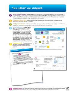


© Copyright 2026