
SOLID WASTE MANAGEMENT FACILITY OPERATIONS
COVANTA NIAGARA, L.P.
SOLID WASTE
MANAGEMENT
FACILITY OPERATIONS
&
MAINTENANCE MANUAL
ADMINISTRATION PLAN
July 2014
TABLE OF CONTENTS
(Table of Contents Contains Clickable PDF Links to the Sections)
CERTIFICATION STATEMENT
May 2014
OM-1
INTRODUCTION
May 2014
OM-A
APPLICABLE REGULATIONS
March 2014
OM-2
ASH MANAGEMENT PLAN
March 2014
OM-3
WASTE CONTROL PLAN
July 2014
OM-4
STAFFING PLAN
July 2014
OM-5
ASH SAMPLING & ANALYSIS PLAN
March 2014
OM-6
OPERATIONS & FACILITY
INSPECTION PLAN
May 2014
OM-7
MAINTENANCE PLAN
July 2014
OM-8
START-UP, SHUT-DOWN, &
MALFUNCTION PROCEDURES
May 2014
EMPLOYEE TRAINING PLAN
May 2014
MISCELLANEOUS OPERATIONAL
REQUIREMENTS
May 2014
CONTINGENCY PLAN
May 2014
CLOSURE PLAN
May 2014
OM-9
OM-10
COVANTA
Doc
PE Certification
Rev.
No. 2
COV ANT A NIAGARA
Revision Date: 5/8/1 4
O&M/ECOM Manual
Reviewed Date:S/811 4
Powering Today. Protecting Tomorrow.
COVANTA NIAGARA, L.P.
This O&M/ECOM Manual has been prepared under the supervision and direction of the below
certifying New York State registered Professional Engineer in accordance with 6NYCRR Part 3601.9(e ). All documents contained herein were prepared in conformance with the NYSDEC
requirements in 6NYCRR Part 360, the ECL, the current Part 360 permit and the proposed Part
360 Permit Modification Documents and all the information contained herein is believed to be true
and accurate. All engineering drawings included herewith were prepared under the supervision
and direction of another certifying New York State registered Professional Engineer.
'
\,
"I
~·
I
\
J •
\,
Chris Schifferli, PE
License 084525
Printed copies are not document controlled, refer to "S" drive, ISO 14001 Environmental Management Systems file
for latest approved version
Page 1of1
0
Doc
OM-1
COVANTA NIAGARA
O&M Manual/ECOM
Rev.
No. 8
Revision Date: 5/8/14
Review Date: 5/8/14
INTRODUCTION
The Covanta Niagara, L.P. facility, located on approximately 27 acres at 100 Energy
Boulevard at 56th Street in Niagara Falls, New York, combusts solid waste in two
Deutsche Babcock Anlagen (DBA) mass burn furnaces and boilers with associated
turbine/generators, flue gas cleaning systems, a refuse storage and feeding system, an
ash residue handling and processing system and a Rail-to-Truck Intermodal Facility
(RTIF). Waste is delivered to Covanta Niagara, L.P. either by over the road truck or by
rail via the operation of the RTIF.
In addition, there is an alternate fuel-fired furnace/boiler, that currently combusts waste
wood (e.g. pallets, construction/demolition wood, clean wood, creosote treated wood,
etc.), with associated alternate fuel storage and feeding system, lime injection system
for acid gas control, electrostatic precipitator, and an ash handling and processing
system. The solid waste and alternate fuels are the primary fuels used in Covanta
Niagara’s two solid waste-fired mass burn furnace/boilers and the alternate fuel-fired
furnace/boiler, respectively, to produce high pressure steam. As the solid waste and
alternate fuels are combusted in their respective furnace/boilers, the heat released is
recovered via the steam produced in the boilers. The steam produced will normally be
put through two extracting/condensing turbines to produce electricity and extracted
steam. Some of the electricity generated (approximately 17%) is used to power
equipment in the plant while the remainder is sold into the power grid. The steam that is
extracted is transported to six (6) neighboring manufacturing plants for use in their
processes.
PURPOSE OF THE MANUAL
This Operations and Maintenance manual is provided to comply with the requirements 6
NYCRR Part 360-1.14 and 360-3 and the requirements set forth in 40 CFR part 60,
Subpart Ea, section 60.56a(f)(6) – “procedures for operating the MWC unit within the
standards established under this subpart”. Detailed descriptions of the Covanta
Niagara processes are found in the Operation Manual's Systems Description book.
WASTE RECEIVING AND MANAGEMENT
Rail:
Delivery schedules of unit trains are established by CSXT and communicated to
Covanta Niagara. Unit train deliveries will be coordinated with the control room operator
to grant CSXT access to the RTIF rail sidings. Each unit train that arrives at the RTIF
includes 30-36 rail cars, each carrying 4 containers for a total of 120-144 sealed
intermodal containers per unit train which will be targeted to be unloaded over 36-48
Printed copies are not document controlled, refer to “S” drive, ISO 14001 Environmental Management Systems file
for latest approved version
Page 1 of 29
Doc
OM-1
COVANTA NIAGARA
O&M Manual/ECOM
Rev.
No. 8
Revision Date: 5/8/14
Review Date: 5/8/14
hours. The net weight of each container is expected to be 20-22 tons. Based on this
expected net weight, each unit train will deliver approximately 2,400-3,200 tons of
MSW.
Prior to receipt by the RTIF, residential MSW is screened and is subsequently loaded
into sealed containers at the Department of Sanitation of New York (DSNY’s) North
Shore and East 91st Street converted Marine Transfer Stations (MTSs). Alternate
facilities are available for receipt of containerized waste from DSNY due to either an
emergency or for long term capacity and is addressed by the Waste Control Plan
(Section 3) of this manual.
Containerized waste received by the RTIF is screened for radiation prior to transport to
the tipping hall to verify radiation screening performed at the MTS to ensure only nonhazardous municipal solid waste is delivered to the Niagara RTIF. No hazardous
wastes will be transported to the RTIF. The Covanta Niagara EfW Facility will not
accept any hazardous wastes, either by rail or truck.
Radio Frequency Identification (RFID) technology is utilized to track container
movements and elapsed time from NYC to Niagara. Passive RFID technology captures
data entering and leaving the facility to assist in the management of containers.
After delivery of the railcars loaded with full containers, the RTIF Superintendent/Lead
Operator will review the RFID container data log, ensure that each container is in good
working order and discern any odors. Any discrepancies need to be immediately noted
and reported to the Rail Transportation Manager. The CSXT Bill of Lading is crosschecked with the RTIF schedule for receipt of containers. Any discrepancies are
immediately noted and immediately reported to the Rail Transportation Manager.
Intermodal containers will be offloaded from the railcars via a dedicated container
handler (Reach Stacker) designed specifically for intermodal container transfer
operations. Full intermodal containers will be lifted from the railcars and then loaded by
the container handler onto a yard tractor with tipping chassis. These tipping chassis will
be specifically designed for the transportation of intermodal containers. The yard tractor
units, with the full intermodal containers, will then proceed to the RTIF scale, or in the
event of an RTIF scale outage, to the EfW Facility scale.
At the scale house, the container identification is verified and container is scanned for
radiation after passing over the scale, the tractor trailer units with the full intermodal
containers will be directed to the tipping floor to be unloaded.
In the event that full intermodal containers require the application of heat in order to
allow the municipal solid waste to be discharged, then the RTIF Superintedent will direct
the tractor driver to enter the thaw shed. The yard tractor units loaded with the full
intermodal container will remain inside the thaw shed for a time sufficient to allow the
Printed copies are not document controlled, refer to “S” drive, ISO 14001 Environmental Management Systems file
for latest approved version
Page 2 of 29
Doc
OM-1
COVANTA NIAGARA
O&M Manual/ECOM
Rev.
No. 8
Revision Date: 5/8/14
Review Date: 5/8/14
outermost portion of municipal solid waste to de-ice and release from the interior walls
of the intermodal containers. The yard tractor units loaded with full intermodal
containers will then proceed to the EfW Facility tipping hall to discharge the municipal
solid waste.
OVER THE ROAD TRUCKS:
Over the road trucks (i.e., front and rear end loaders, rolloffs, transfer trailers, dump
trailers, van trailers, flat bed trailers, tank trailers, etc.) hauling solid waste enter the
facility grounds through a monitored entry gate off 56th street and proceed to the
scalehouse via Energy Boulevard where they are weighed on computerized scales for
record keeping and billing purposes. At the scalehouse, the load is identified. The
hauler/generator must have a contract with Covanta Niagara and be in the scalehouse
computer system, otherwise the load will be refused entry. If the generator/hauler is the
scalehouse computer system, this indicates that there is a contract in place, that the
waste type has been reviewed for suitability for acceptance and that the generator has
been informed as to what wastes are acceptable and what wastes are not acceptable.
As reflected in the facility's Waste Control Plan (Section 1) no hazardous waste,
radioactive waste, or regulated medical waste are accepted.
All solid waste unloading (with the exception of the tank trailers of liquid waste for the
liquid injection system), storage and handling are done inside buildings. Trucks with
acceptable loads proceed to either the tipping hall or the liquid waste unloading
(secondary containment) area. Inside the tipping floor, the transfer trailers and dump
trailers are normally backed up and unloaded directly into the large concrete refuse
bunker. The refuse bunker is designed to provide three to four days of storage
capacity. This storage capacity allows the facility to handle short term waste flow
fluctuations. The smaller waste delivery trucks (i.e. packers and rolloffs) are unloaded
on the tipping floor and then a payloader is used to push these loads into the refuse
bunker. Van trailers containing pallets of various wastes: drums (liquids and solids),
super sacks of powder and boxes of consumer packaged products, are unloaded by
forklift using a portable unloading dock. After the pallets of boxes are unloaded, they
are normally pushed (by the payloader) directly into the refuse bunker. Pallets of fiber
drums and super sacks containing powders are temporarily stored on the tipping floor
(either the south or north ends) and then put into the refuse bunker, one or two pallets
at a time, so that they can be picked up by the grapple crane and put directly into the
furnace hopper without breaking the container and creating a dust cloud. Most pallets
of drums (steel, plastic or fiber) and totes (plastic or mild steel) with liquids or solids are
temporarily stored in the drum storage area at the north end of the tipping floor until the
containers can be processed through the Komar shredder. After discharging their
loads, the trucks leave the tipping floor.
Printed copies are not document controlled, refer to “S” drive, ISO 14001 Environmental Management Systems file
for latest approved version
Page 3 of 29
Doc
OM-1
COVANTA NIAGARA
O&M Manual/ECOM
Rev.
No. 8
Revision Date: 5/8/14
Review Date: 5/8/14
A Komar shredder (approved by the NYSDEC in October 2002) was installed on the
tipping floor to process drums (steel, plastic and fiber) and tote containers (mild steel
and plastic). The drums and totes can contain liquids, solids or semisolids. The drums
and totes are put into the shredder where an auger pushes the containers against a
shear plate which results in the container being torn apart. As the container gets torn
apart, the auger pushes the contents, as well as, pieces of the container out the
discharge chute and onto the solid waste in the refuse bunker.
The refuse bunker is completely enclosed and contains two full-span, overhead
traveling cranes. Grapples on the cranes are used to pick up the solid waste and put it
into the furnaces feed hoppers. The solid waste then slides by gravity into the refuse
chute, where it acts as an airlock to impede entry of air from the feeding system into the
furnace. A ram feeder pushes the solid waste from the bottom of the refuse chute onto
the boiler's uppermost roller grate. The feeder then retracts, ready to feed more solid
waste onto the grate. The rate at which solid waste is fed onto the grate depends on the
demand for steam, the heating value of the solid waste being fed, its moisture content,
and several other factors. The feed rate is altered by changing the cycle time of the ram
feeder. When a change in the feed rate is made, corresponding adjustments to roller
speeds and primary and secondary air flows are made to maintain combustion control.
Primary air distribution to individual rollers is controlled to ensure burnout of the waste.
Each crane is operated from a common air-conditioned pulpit, and each is able to
satisfy the fuel requirements for each of the two furnaces.
Bulk liquid wastes arrive at the facility in tank trailers (nominal size – 5,000 gallons). Most
of those tank trailers are staged in a concrete secondary containment dike on the north
side of the DBA boiler building and then the liquid is pumped from the trailer, through a
strainer and into a storage tank. Occasionally a tank trailer is taken to the tipping floor and
the liquid then sprayed from the tanker onto the solid waste in the refuse bunker.
A liquid waste injection system (approved by the NYSDEC in March 2003) is used to inject
the liquid waste directly into the combustion zone of the DBA boilers. Six permanent
storage tanks were installed in 2011 inside a concrete secondary containment dike. The
tanks have a total storage capacity of 300,000 gallons. From the tanker the liquid waste
flows through a strainer (to remove solids that would plug the injection nozzles), then into a
pump, through a grinder and then into one of the storage tanks. From the storage tank
the liquid waste directly (through spray nozzles) into the combustion zone of the DBA
boilers.
The direct injection liquids are the only wastes that are not put into the refuse bunker prior
to being put into the furnace.
The facility effectively controls odors; all refuse handling occurs in the enclosed tipping
hall and refuse bunker areas which are maintained under a slight negative air pressure.
Printed copies are not document controlled, refer to “S” drive, ISO 14001 Environmental Management Systems file
for latest approved version
Page 4 of 29
Doc
OM-1
COVANTA NIAGARA
O&M Manual/ECOM
Rev.
No. 8
Revision Date: 5/8/14
Review Date: 5/8/14
Primary air for the furnace is drawn from the tipping hall and refuse bunker so that solid
waste odors, as well as truck exhaust fumes are swept into the furnace and combusted.
The liquid waste storage tanks are vented into the primary air ducts for each of the two
DBA boilers - thus there is slight negative pressure on the storage tanks and any air
venting from the tanks is burned in the boilers.
COMBUSTION PROCESS
The Deutsche Babcock Anlagen (DBA) Duesseldorf Roller Grate system technology,
developed in Germany and used throughout the world, is used at the Covanta Niagara
facility. Proper combustion of solid waste is based on three fundamentals: time,
temperature, and turbulence.
The Duesseldorf Roller Grate consists of six rotating rollers each approximately 5 feet in
diameter and made of ductile iron bars that extend the full width (approximately 22 feet)
of the furnace. The roller grates are installed on a 20% incline from the first to sixth
grate. Each roller is independently driven through a gear box that enables its rotational
speed to be varied from about 0.6 to 12 revolutions per hour. The solid waste tumbles
and mixes as it travels over the roller grates. The furnace walls are constructed of steel
tube panels of membrane construction. Water flows in the tubes and heat from the
combustion of the solid waste is transferred through the tubes into the water, and steam
is produced.
Primary air for combustion is blown into each of the roller grates, and spaces between
the bars allows the combustion air to penetrate the solid waste. As each roller rotates
forward, the solid waste slowly moves toward the next lower roller. Between each of the
rollers a transition piece causes the solid waste to tumble and roll, an action that
exposes previously unburned solid waste to the fire and air in the furnace. The
Duesseldorf Roller Grate system is designed in this manner to allow a through burnout
of solid waste.
While on the first roller and at least part of the second roller, the solid waste is dried by
the hot combustion gases produced from the solid waste combustion on the lower roller
grates. The dried solid waste ignites as it crosses the second roller, and burns
thoroughly as it travels across the third and fourth rollers; occasionally, wet or low heat
content waste may continue to combust on the fifth roller grate as well. The burnout is
completed as the bottom ash passes over the sixth roller and ultimately falls off into the
water-impounded bottom ash extractor trough below.
The hot combustion gases from the combusted solid waste flow upward from the lower
furnace through the upper furnace, heating the water in the wall tubes. The combustion
gases then pass through the screen tube section and then through several passes
Printed copies are not document controlled, refer to “S” drive, ISO 14001 Environmental Management Systems file
for latest approved version
Page 5 of 29
Doc
OM-1
COVANTA NIAGARA
O&M Manual/ECOM
Rev.
No. 8
Revision Date: 5/8/14
Review Date: 5/8/14
containing the superheater and economizer sections. In the upper sections of the
boiler, urea is injected through a series of nozzles for nitrogen oxides control. The urea
reacts with the nitrogen oxides to form nitrogen. After the economizer section, the
combustion gases flow into the boilers’ air pollution control system’s acid gas scrubber.
Steam is generated in the wall and screen tubes and flows through riser tubes into the
steam drum. In the steam drum, water and steam are separated. The water is returned
to the lower headers of the wall tubes, while the steam is piped through the boiler’s
superheater tubes to increase the steam’s temperature. Steam leaves the superheater
and enters the main steam header and is transported to the facility’s two turbine/
generators to produce electricity.
Each boiler is equipped with two ignition burners and two auxiliary burners that can fire
natural gas. The burners are operated at the following times to facilitate the combustion
process.
Furnace start-up prior to introduction of solid waste;
Furnace shut-down after solid waste feed has been discontinued until burnout of the
solid waste in the furnace has occurred; and
Other times as needed to ensure the combustion gases are subject to high
temperature residence time.
Basic Combustion Theory Applicable to a Municipal Waste Combustion (MWC) Unit
The following description is provided in accordance with 40 CFR Part 60, Subpart Ea,
section 60.56a (f) (2) - description of basic combustion theory applicable to MWC units.
The proper combustion of solid waste is based on three fundamentals: time,
temperature, and turbulence. The DBA boilers grates and furnace systems are
designed and constructed to obtain complete combustion of solid waste, a highly
variable fuel.
The combustion of any fuel requires a theoretical (stoichiometric) amount of oxygen
which is usually supplied from ambient air. In practical applications, because of the
incomplete mixing of the fuel and air, this stoichiometric amount of air is not enough to
complete the combustion of all the fuel. In order to complete the process and have no
unburned solid waste passing through the furnace, an extra amount of combustion air is
supplied above the stoichiometric amount. This extra air is called “excess air” and will
vary depending on the type of fuel being burned, but for solid waste will typically range
from 60 to 100% of the stoichiometric amount. As stated above, the DBA furnace’s
Printed copies are not document controlled, refer to “S” drive, ISO 14001 Environmental Management Systems file
for latest approved version
Page 6 of 29
Doc
OM-1
COVANTA NIAGARA
O&M Manual/ECOM
Rev.
No. 8
Revision Date: 5/8/14
Review Date: 5/8/14
primary air fan pulls the combustion air from the solid waste bunker and tipping floor
area and directs it into the furnace through the roller grates.
As the solid waste burns on the rollers, its volume decreases. An adequate bed depth
of solid material on the surface of the rollers is maintained by adjusting relative
rotational speeds of the rollers. This bed of solid waste protects the grate bars from
intense heat in the furnace and provides a bed of combustible material deep enough to
make good contact with the primary air. The ability to independently adjust the rate at
which the solid waste passes across succeeding rollers in the grate as well as the
quantity of air flowing through the individual roller grates contributes to proper burnout
and a steady fire. In the DBA "parallel flow" design that is used at Covanta Niagara, the
flue gas generated during the combustion of fuel over the initial rollers is forced to flow
parallel to the remaining rollers. This increases the turbulence and the time that the flue
gas spends in the primary combustion zone. After leaving this zone, secondary air is
injected into the flue gas stream. Once again, further turbulence is created and the
additional air promotes the completion of combustion of any unburned organic
compounds and carbon monoxide remaining in the flue gas. By maintaining the proper
primary and secondary air flow, a constant feed of solid waste into the furnace, and
proper solid waste/ ash depth on the roller grates, a furnace temperature adequate for
good combustion can be maintained.
In summary the DBA furnace design incorporates the basic requirements of good
combustion by:
lengthening the time for combustion ( the time the solid waste is in the furnace)
using slowly rotating roller grates, by directing the combustion gases generated from
the solid waste on the first sets of roller grates over the remaining roller grates, and
adding secondary air after the initial combustion zone in order to complete the
combustion of volatiles in the flue gas.
maintaining sufficient temperature - typically 1800 to 2300 F in the primary
combustion zone.
creating a turbulent combustion zone through the combination of primary air injection
from the roller grates, forcing the flue gas initially generated to turn back and mix
with the combustion gases generated on the last roller grates, and finally injecting
secondary air into the furnace.
Procedure to Maintain Proper Combustion Air Supply Levels
The following description is provided in accordance with 40 CFR Part 60, Subpart Ea,
section 60.56a (f) (5) - procedures for maintaining proper combustion air supply levels.
Printed copies are not document controlled, refer to “S” drive, ISO 14001 Environmental Management Systems file
for latest approved version
Page 7 of 29
Doc
OM-1
COVANTA NIAGARA
O&M Manual/ECOM
Rev.
No. 8
Revision Date: 5/8/14
Review Date: 5/8/14
As described above, air in excess of the stoichiometric quantity needed to combust the
solid waste is supplied to the DBA furnace. The air enters the furnace as primary air
through the roller grates and as secondary air through nozzles located above the
grates. The flue gas oxygen concentration and carbon monoxide concentration are
monitored in the boiler’s final flue gas pass, after all combustion has been completed.
In addition the operating conditions of the primary and secondary air fans are
monitored.
Plant operators, in particular the control room operators (CRO) who actually run the
DBA furnace/ boilers are trained and are aware of the requirements for proper
combustion, and the relationship between oxygen and carbon monoxide concentrations.
The typical range for flue gas oxygen concentration is 5 to 7 % with a carbon monoxide
concentration of less than 100 ppm corrected to seven (7) percent oxygen. Each unit
has a dedicated continuous emission monitoring system (CEMS). The CEMS data
acquisition system will collect and tabulate all the monitors outputs and will alarm in the
control room if a parameter, such as flue gas oxygen concentration, is out of the proper
range. The CROs monitor various parameters and make adjustments in the controls,
as necessary, to maintain proper combustion air levels and overall good combustion of
the solid waste.
ASH RESIDUE HANDLING
The solid waste combustion process results in two ash residue streams: the heavy
residue from the roller grates - bottom ash, and the lighter residues from the pollution
control system - flyash and scrubber salts. As the solid waste completes the burning
process on the roller grates, bottom ash falls through ash chutes into the water filled ash
extractor tank, entering below the water line. The water cools the ash and also serves
as a seal to prevent air leakage into the furnace. A hydraulic ram extractor, submerged
below the water level pushes the ash up an inclined chute (to allow free moisture to
drain back into the tank) and onto one of two vibratory slipstick conveyors. The
vibratory slipstick conveyors, common to both furnaces, transport the ash the width of
the boiler building, and discharge it onto belt conveyors that transport the ash to the ash
processing building. The belt conveyor is located inside an enclosed gallery.
AIR POLLUTION CONTROL SYSTEM
In addition to providing a general description of the air pollution control equipment, this
description is provided in accordance with 40 CFR Part 60, Subpart Ea section 60.56a
(f) (8) - procedures for minimizing the particulate matter carryover.
In the air pollution control system, the light flyash residue that is entrained in the flue
gas during the combustion process as well as the acid gases produced during the
combustion process are removed. After leaving the boiler, the flue gas passes through
Printed copies are not document controlled, refer to “S” drive, ISO 14001 Environmental Management Systems file
for latest approved version
Page 8 of 29
Doc
OM-1
COVANTA NIAGARA
O&M Manual/ECOM
Rev.
No. 8
Revision Date: 5/8/14
Review Date: 5/8/14
a flue gas cleaning system which consists of a dry scrubber followed by a reverse air
baghouse. In the scrubber, a lime slurry is injected into the flue gas stream using rotary
atomizers (which create a very fine mist.) When the mist contacts the flue gas, the
water evaporates which cools the flue gas while the lime particles react with the
hydrochloric acid, sulfur dioxide, hydrofluoric acid, etc. removing those pollutants as
calcium salts. The water content of the lime slurry can be adjusted to control the
temperature of the flue gas existing the scrubber while the lime content of the slurry can
be varied to achieve the required sulfur dioxide removal. Activated carbon, for mercury
control, is injected into the flue gas duct between the scrubber and the baghouse.
Exiting the scrubber, the flue gas flows through duct work into an eight module reverse
air, fabric filter baghouse. In the flue gas duct just upstream of the baghouse activated
carbon, for mercury control, is injected. In the baghouse the fine particulate flyash,
scrubber salts and activated carbon are removed. The reverse air baghouse has a
lower air-to-cloth ratio (more cloth for filtering the flue gas) than the typical pulse jet
baghouse and significantly lower emissions are expected. The baghouse will utilize
woven fiberglass bags with an acid resistant finish. The flow of flue gas is upward and
from inside to the outside of bags. When accumulated on the inside of the bags, flyash
scrubber salts /unreacted lime and activated carbon create an additional filtering
substrate to provide additional removal of unreacted acid gases, as well as very efficient
removal of particulates, metals, mercury and trace organics. Each module is equipped
with isolation dampers that allows the bag cleaning cycle to cascade from module to
module. During the cleaning cycles, the reverse air fan gently blows air in the reverse
direction from the flue gas flow and dislodges some of the flyash/ scrubber salts built up
on the inside of the bags. The dislodged ash is collected in the baghouse ash hoppers,
and then transported in sealed conveyors to the ash processing building where it is
wetted with water in a plugmill to prevent fugitive dust emissions, and then discharged
onto the loadout belt with the bottom ash for loadout into trucks for transport to the
landfill. The fabric filter baghouse is designed to limit particulate emissions from each
boiler to 0.01 grains per dry standard cubic foot corrected to 7% oxygen.
From the baghouse the flue gas is pulled into the induced draft (ID) fan and then
discharged out the stack. The flue gas continuous emission monitoring system is
located in the flue gas duct after the baghouse upstream of the ID fan.
CONTINUOUS EMISSION MONITORING SYSTEM
In addition to providing a general description of the facility's continuous emission
monitoring system (CEMS), this description is provided to comply with 40 CFR Part 60,
Subpart Ea, section 60.56a (f) (11) - procedures for monitoring MWC unit emissions.
Each of the two DBA combustion units is equipped with a dedicated CEMS to measure
various constituents of the flue gas exiting each boiler and each pollution control
system. Each CEM system includes both extractive and in situ components.
Printed copies are not document controlled, refer to “S” drive, ISO 14001 Environmental Management Systems file
for latest approved version
Page 9 of 29
Doc
OM-1
COVANTA NIAGARA
O&M Manual/ECOM
Rev.
No. 8
Revision Date: 5/8/14
Review Date: 5/8/14
The extraction system component uses a dilution probe for sample handling and is an
integrated system purchased from Enviroplan, Inc. It includes sample probe, sample
transport, analyzers, and support hardware. The data acquisition, storage, calculations,
and reporting is done by a system purchased from Trace Environmental Systems,
Incorporated. Components of the Trace system will also control the sequencing of the
automatic calibration feature of the CEMS. Most of the components of the extractive
system and the data reporting system are in the CEMS shelter which is located at
grade, between the two DBA boiler trains, beneath the scrubbers. Flue gas
components measured by analyzers located in the CEMS shelter are: Sulfur Dioxide
(SO2), nitrogen oxides (NOX), carbon monoxide (CO), and carbon dioxide (CO2). An
extraction dilution probe is located in the flue gas duct just upstream (boiler outlet) of the
acid gas scrubber. SO2 and CO2 are analyzed in the flue gas from this sampling point.
After the scrubber and baghouse a second extraction dilution probe is located in the flue
gas duct just upstream of the ID fan. SO2, NOx, CO and CO2 are measured in the flue
gas from this sampling point.
Flue gas oxygen (O2) concentration (measured for boiler control purposes only),
opacity, furnace temperature, and scrubber outlet temperature are also measured by insitu devices. Measurement signals from in-situ analyzers are transmitted to the data
acquisition system (DAS) that is housed in the CEMS shelter. The O2 analyzers are
located in the flue gas duct adjacent to the extraction systems' dilution probes, while the
opacity analyzers are located in each flue gas duct upstream of the inlet to the ID fan.
The furnace temperature thermocouples are installed at the top of the section of the
boiler's first pass, two on each side. The scrubber outlet instrumentation is installed in
the scrubber outlet duct. Measurement data from the in situ analyzers are transmitted
to the Trace system housed in the CEMS shelter.
Flow monitors have now been installed in the flue gas duct at the ID fan to measure the
flue gas flow rate for each of the DBA boilers. The signal from each flow monitor is
transmitted to the DAS and is used in calculating the mass emissions – CO2.
The data reporting system is integrated with emissions measurement equipment to
digitize, record, and present CEM data. The system also controls the calibration and
sample system automation. The system continuously acquires data values and status
information from pollutant and process measurements, computes emission, forms
averages, detects alarms, provides emission summary reports in hard copy, and allows
for easy preparation of regulatory reports.
The Trace computer system also receives the analog values from the analyzers and
calculates three different averages, forms calibration results and performs data validity
checking. The data recording system consists of a personal computer (PC) running
Printed copies are not document controlled, refer to “S” drive, ISO 14001 Environmental Management Systems file
for latest approved version
Page 10 of 29
Doc
OM-1
COVANTA NIAGARA
O&M Manual/ECOM
Rev.
No. 8
Revision Date: 5/8/14
Review Date: 5/8/14
Trace’s software. It features menu selections for most data entries. It can detect alarm
conditions based upon status inputs. The software can calculate such things as:
Emissions on a lb/hr basis,
Removal efficiency,
Combustion efficiency,
Boiler operating days,
Excess emission alarms, and
Analog alarms in bar chart or strip chart display.
Data are collected in monthly data files located in the computer's hard disk drive. The
Trace system produces a variety or reports, including data, calibration, and alarm logs.
Daily and monthly summary data reports are also available on demand. The Trace
system is also helpful in supporting daily quality assurance activities. Routine reports
and other procedures can be executed with a single command.
The alarm workstation is located in main control room. This PC provides the control
room operator with a real-time display of current data, trends and alarm conditions.
Alarms will be configured to detect emission exceedances. Normally the operator will
receive a warning alarm that a parameter is nearing a permit limit. This alarm will allow
the operator time to react and take actions to prevent the excursion. Any permit limit,
such as hourly, daily averages, may be checked.
FERROUS/NON-FERROUS METAL RECOVERY
The DBA facility will recover both ferrous and nonferrous metals from the bottom ash
residue and recycle those metals. At this time there are no components in the flyash
stream that can be economically recovered. The ferrous/nonferrous metal recovery
processes are located in the ash processing building.
As discussed previously, the bottom ash is transported from the boilers’ ash extractors
to the ash processing building by vibratory conveyors and belt conveyors. In the ash
processing building the bottom ash residue is discharged onto a finger sizer to separate
bulky items greater than 6 inch size from the ash (less than 6 inch size). The bulky
items are conveyed over a drum magnet to recover the ferrous metal, while the
undersized ash is conveyed under a second drum magnet to remove the smaller ferrous
metals. Both ferrous metal streams from the magnets discharge into a common pile for
subsequent loadout and transport to a scrap mill.
After the drum magnet, the bulky material not pulled out by the magnet is discharged
into a truck for subsequent transport back to the refuse bunker or, if necessary,
transport to a landfill, while the remainder of the undersized ash is conveyed to a set of
Printed copies are not document controlled, refer to “S” drive, ISO 14001 Environmental Management Systems file
for latest approved version
Page 11 of 29
Doc
OM-1
COVANTA NIAGARA
O&M Manual/ECOM
Rev.
No. 8
Revision Date: 5/8/14
Review Date: 5/8/14
vibratory screens where material greater than 3/8 inch is separated and conveyed over
an eddy current system to remove nonferrous metals. The less than 3/8 inch ash that
goes through the screen is conveyed to a second eddy current system in order to
remove the smaller nonferrous metals. The remaining ash from both eddy current
systems is discharged on to conveyor belts, mixed with flyash/scrubber salt and loaded
out in trucks for transport to the landfill.
RECORDKEEPING AND REPORTING REQUIREMENTS FOR SOLID WASTE FIRED
BOILERS
This description is provided to comply with 40 CFR Part 60, Subpart Ea, section 60.56a
(f) (12) – reporting and recordkeeping procedures.
The following information must be recorded in computer readable format and on paper:
all 6-minute average opacity levels
all 1-hour average sulfur dioxide emission rate s at the outlet of the acid gas
control device ( inlet as well if compliance is to be based on percent reduction)
all 1-hour nitrogen oxides emission rates
all 1-hour carbon monoxide emission rates
all 1-hour steam load measurements
all 1-hour particulate matter control device inlet temperatures
The following average rates must be computed and recorded:
All 24-hour daily geometric average sulfur dioxide emission rates (percent
reduction , if used)
All 24-hour daily arithmetic average nitrogen oxides emission rates
All 4-hour block arithmetic average carbon monoxide
All 4-hour block arithmetic average steam load levels
All 4-hour block arithmetic average particulate matter control device inlet
temperatures
The following information must be identified:
Operating days when any of the average emission rates (percent reduction, if
applicable) or operating parameters, specified above, or the 6-minute opacity
average exceeds the applicable limit. Also include the reasons for the
exceedance and a description of the corrective actions taken.
Operating days for which the minimum number of hours of sulfur dioxide or
nitrogen oxides emissions or operational data (carbon monoxide, steam load,
particulate matter control device temperature) have not been obtained. Also
Printed copies are not document controlled, refer to “S” drive, ISO 14001 Environmental Management Systems file
for latest approved version
Page 12 of 29
Doc
OM-1
COVANTA NIAGARA
O&M Manual/ECOM
Rev.
No. 8
Revision Date: 5/8/14
Review Date: 5/8/14
include the reasons for the exceedance and a description of the corrective
actions taken.
Times when sulfur dioxide or nitrogen oxides emission or operational data
(carbon monoxide, steam load, particulate matter control device temperature)
have been excluded from the calculation of average emission rates or
parameters and the reasons for excluding data.
The results of the daily sulfur dioxide, nitrogen oxides and carbon monoxide CEMS drift
tests and the accuracy assessment must be recorded.
The results of all annual performance tests conducted to determine compliance with
particulate matter, dioxin/furan and hydrogen chloride limits must be recorded. Also for
all the dioxin/furan tests, the maximum demonstrated steam load and maximum
demonstrated particulate matter control device temperature must be recorded.
Semiannually, compliance reports for sulfur dioxide, nitrogen oxide, carbon monoxide,
steam load and particulate matter control device temperature must be submitted to EPA
and NYSDEC. The report must include: dates, 24-hour block data, 4-hour block data,
identification of days when the minimum number of hours was not obtained,
identification of times when data was excluded and results of the CEMS daily calibration
drift check (only days when drift was excessive). Note Niagara submits this report on a
quarterly basis – “Excess Emissions Report”.
Semiannually, a report must be submitted for any pollutant or parameter that does not
comply with the specified limits. Note Niagara submits this report on a quarterly basis –
“Excess Emissions Report”.
The annual compliance stack test report must be submitted to the EPA and NYSDEC.
ALTERNATE FUELED-FIRED FURNACE/BOILER PROCESS
The alternate fuels (i.e. waste wood) are received into the facility and weighed through
the scalehouse in the same manner as the solid waste. Waste wood is received either
as whole / semi whole pieces (unprocessed) or already shredded. After being weighed
in, the trucks with the unprocessed waste wood then proceed to “C” building storage
area.
Printed copies are not document controlled, refer to “S” drive, ISO 14001 Environmental Management Systems file
for latest approved version
Page 13 of 29
Doc
OM-1
COVANTA NIAGARA
O&M Manual/ECOM
Rev.
No. 8
Revision Date: 5/8/14
Review Date: 5/8/14
On an “as needed basis” the waste wood that is shredded on site is transported from
the storage pile to the “C” building storage area. The shredded wood is unloaded and
then pushed up into a pile using a bulldozer.
“C” building has storage capacity for several thousand tons of alternate fuels. In this
storage area, parascrews on either side of an A-frame traverse, under the piled
alternate fuels, the length of the building and push the fuel onto a transport system,
consisting of two parallel conveyor belt systems (each has three belts in series), that
transport the fuel to a surge bin at the top of alternate fuels furnace/boiler.
From each surge bin, which can store approximately 20 minutes of alternate fuels at
normal boiler feed rates, screws on the bottom of each bin push the fuel down chutes
into the furnace.
Combustion Process
As the alternate fuels enter the furnace, air swept distributor spouts at the bottom of the
chutes help propel the alternate fuels into the furnace; the less dense particles burn in
suspension and the denser material falls to and burns on the grates.
The alternate fuel-fired furnace grate system, rotograte stokers, consists of four parallel
trains of traveling grates each carried on two chains which are driven from the rear of
the furnace toward the front by a drive and sprocket assembly. Primary air would be
introduced below the grates providing the air required for combustion of the alternate
fuels on the grate. Holes in the bars allow the proper distribution of primary air to the
unburned fuel on the grates. By the time the grate traverses the bottom of the furnace,
the combustion process of the alternate fuels on the grate is completed. The ash which
remains drops off the grate, through the ash chutes. The siftings ash which falls
through he grates passes through the sifting hopper into the same quench tank.
Secondary air admitted above the grate would provide additional air for turbulence and
combustion of the suspended material as well as the volatile gases from partially
combusted material from the grate.
The rate at which alternate fuels would be fed to the grate would depend on the demand
for steam, the healing value of the fuel being fed, its moisture content, and several other
factors. Changes in the feed rate would result in corresponding adjustments to grate
speed and air flow to maintain combustion control. Air distribution to the grates and
secondary air nozzles would be controlled to ensure burnout of the alternate fuels.
Auxiliary burners would be operated as necessary at the following times:
(1)
furnace start-up prior to introduction of alternate fuels;
(2)
furnace shut-down;
Printed copies are not document controlled, refer to “S” drive, ISO 14001 Environmental Management Systems file
for latest approved version
Page 14 of 29
Doc
OM-1
COVANTA NIAGARA
O&M Manual/ECOM
(3)
Rev.
No. 8
Revision Date: 5/8/14
Review Date: 5/8/14
During periods of malfunction.
Air Pollution Control
To control acid gases (sulfur dioxide and hydrochloric acid) hydrated lime is injected
directly into the furnace. Urea is also injected into the furnace in order to control
nitrogen oxide emissions. In addition activated carbon is injected into the flue gas at the
outlet of the economizer in order to control trace organic compounds. The calcium salts
of the acid gases and the activated carbon, as well as, the flyash produced during the
combustion process are removed in the electrostatic precipitator on collector plates.
Periodically, the collector plates are rapped and the flyash falls down into the flyash
hoppers and into sealed drag chain conveyors which transport the flyash to an ash silo.
Ash Residue Handling and Disposal
In the bottom ash quench tank, a drag chain pulls the bottom ash out of the tank and
discharges it into the ash hopper. When the ash hopper is full, it is taken to the tipping
floor and dumped into the DBA refuse bunker. This ash is then processed through the
DBA furnaces. From the ash silo, the flyash goes through a rotary feeder into a pugmill
where the flyash is wetted to prevent dusting. From the pugmill the wetted flyash drops
into the ash truck that transports the ash to the landfill.
Continuous Emission Monitoring System – Alternate Fuel Fired Furnace/Boiler
The alternate fuel -fired furnace/boiler system is equipped with a dedicated CEMS. The
CEMS sampling system is an extractive type, located in the stack, and the monitors
include carbon monoxide, sulfur dioxide, nitrogen oxides, and oxygen. In addition, there
is an in situ stack flue gas opacity monitor. A Trace Environmental System data
acquisition system (DAS) is integrated with the emissions measurement equipment to
digitize, record, present CEM data. The system also controls the daily calibration
checks, and sampling systems purges and sampling.
Printed copies are not document controlled, refer to “S” drive, ISO 14001 Environmental Management Systems file
for latest approved version
Page 15 of 29
Doc
OM-1
Rev.
No. 8
Revision Date: 5/8/14
Review Date: 5/8/14
COVANTA NIAGARA
O&M Manual/ECOM
Major Modifications to the Introduction
March 2009
The “Recordkeeping and Reporting” section on page 12 was revised to reflect the type
of data that is recorded in the computer
March 2011
The “Continuous Emission Monitoring System” section on page 8 was revised to include
the DBA boilers’ new flue gas flow monitors.
March 2012
The “Solid Waste Receiving, Storage and Handling” section, on page 3, was revised to
reflect the changes made to the liquid waste storage tanks and pumping system.
Appendix 1 was added
Combustion Unit
- Basic Combustion Theory Applicable to a Municipal Waste
April 2013
The “ferrous / nonferrous metal recovery” was modified to reflect the new nonferrous
process for recovering the less than 3/8 inch metal.
March 2014
The system description for the RTIF was added. Wood staging area text was removed
as that area is no longer used.
May 2014
Minor QA/QC updates.
Printed copies are not document controlled, refer to “S” drive, ISO 14001 Environmental Management Systems file
for latest approved version
Page 16 of 29
Doc
OM-1
Rev.
No. 8
Revision Date: 5/8/14
Review Date: 5/8/14
COVANTA NIAGARA
O&M Manual/ECOM
APPENDIX 1
COMBUSTION THEORY
Printed copies are not document controlled, refer to “S” drive, ISO 14001 Environmental Management Systems file
for latest approved version
Page 17 of 29
Doc
OM-1
Rev.
No. 8
Revision Date: 5/8/14
Review Date: 5/8/14
COVANTA NIAGARA
O&M Manual/ECOM
Basic Combustion Theory Applicable to a Municipal Waste Combustor Unit
THE FUEL - Municipal Solid Waste (MSW)
Combustion is a process in which fuel combines rapidly with oxygen to produce heat
and product gases. Figure 1 illustrates the process.
Fuel
Flue Gas
Carbon,
Hydrogen,
Oxygen
Nitrogen
Carbon Dioxide
Water
Combustion
Air
Nitrogen
Oxygen
Heat
The fuel is municipal waste, which contains a mixture of paper, plastics, wood, yard
waste, food, textiles, and various other materials. The combustible part of these
materials consists primarily of carbon and hydrogen. Most of these materials also
contain oxygen. MSW is composed of volatile fractions - which burn as a gas, and fixed
carbon - which burns as a solid.
Most of the materials in MSW are mixtures of many different chemical compounds. For
example, wood contains thousands of different chemical substances. However, most of
the important combustion reactions can be understood by just considering a few of the
major compounds in the waste stream. By far, the most important elements involved in
MSW combustion are
C – Carbon
H – Hydrogen
Printed copies are not document controlled, refer to “S” drive, ISO 14001 Environmental Management Systems file
for latest approved version
Page 18 of 29
Doc
OM-1
Revision Date: 5/8/14
Review Date: 5/8/14
COVANTA NIAGARA
O&M Manual/ECOM
Rev.
No. 8
O – Oxygen
These elements are combined in many different compounds which are termed
hydrocarbons, because they contain large amounts of hydrogen and carbon. These
hydrocarbons are the primary sources of energy in the fuel. When carbon or hydrogen
reacts with oxygen, the reaction is called exothermic, meaning that heat is produced by
the reaction.
Two primary reactions occur during combustion of any hydrocarbon fuel:
carbon combines chemically with oxygen to produce carbon dioxide and heat
C + O2 CO2 + heat
hydrogen combines with oxygen to produce water vapor and heat.
4H + O2 2H2O + heat
The carbon dioxide and water vapor leave the furnace as flue gas.
In addition to carbon, oxygen, and hydrogen, MSW contains a number of other
elements including
Chlorine and Sulfur
Much of the chlorine combines with hydrogen to produce hydrogen chloride, a
highly reactive chemical which becomes hydrochloric acid when combined
with water.
2Cl + H2 2HCl
Sulfur combines with oxygen to form sulfur dioxide, which dissolves in water
to form sulfuric acid.
S + O2 SO2
Alkaline metals
These materials - which include sodium, potassium, calcium, and magnesium
- are present in many waste materials including wood and wood products.
They occasionally show up in a pure form. They are highly reactive and
combine readily with oxygen to form solid particles, but also with chlorine to
Printed copies are not document controlled, refer to “S” drive, ISO 14001 Environmental Management Systems file
for latest approved version
Page 19 of 29
Doc
OM-1
COVANTA NIAGARA
O&M Manual/ECOM
Rev.
No. 8
Revision Date: 5/8/14
Review Date: 5/8/14
form salts which melt or vaporize in the high temperature combustion regions.
These salts can also exist as corrosive liquids on boiler tube surfaces. In
pure form, they are extremely combustible, easily ignited, and can react with
water or steam to produce hydrogen.
Heavy metals
These elements, such as lead, zinc, and cadmium, are present in a variety of
materials including electronic equipment, paints, and tires. These metals
react with chlorine to form metallic salts which are corrosive to boiler tubes.
In addition to the materials described above, trash also contains some things that don’t
burn, such as water, glass, metal, and dirt. These materials absorb heat from the
burning refuse and are known as heat sinks. Water is the most important of these
materials for two reasons:
1. There can be a lot of water in waste. MSW is typically about 15% water, but
after a lot of rain that value can be much higher, and
2. Water absorbs a lot of energy as it heats up and turns to steam. When a
pound of water and a pound of metal enter the furnace in the fuel, the water
takes with it about 30 times as much heat as the metal when it leaves the
boiler.
THE STAGES OF COMBUSTION FOR MSW
Most fuels are relatively pure materials, and burn in a consistent and repeatable
manner. Unlike these fuels, MSW is a mixture of many different materials and each of
these affects the overall combustion process. Some important aspects of MSW
combustion are:
1.
2.
3.
Moisture content and fuel drying
Volatile content and devolatization
Fixed carbon combustion, or burnout
MSW combustion involves all the mechanisms described above, and occurs in several
stages, with the duration of each stage depending on the particular fuel. These stages
include:
Heating and drying. The fuel must be heated and dried before it can burn. The heat is
supplied by the active combustion of nearby fuel, and in some cases by preheated
primary combustion air. Clearly, fuels with higher water content require more energy to
dry.
Printed copies are not document controlled, refer to “S” drive, ISO 14001 Environmental Management Systems file
for latest approved version
Page 20 of 29
Doc
OM-1
COVANTA NIAGARA
O&M Manual/ECOM
Rev.
No. 8
Revision Date: 5/8/14
Review Date: 5/8/14
Devolatization. As the fuel heats up, it begins to break down chemically. During this
process the volatile fraction of the waste is released into the gas stream. These volatile
materials include the hydrogen and some of the carbon contained in the fuel. They are
emitted as heat vaporizes the lighter compounds, and breaks apart the chemical bonds
within heavier hydrocarbon molecules to release combustible gases. The gases
evolved from the waste include a wide range of light hydrocarbons, including methane,
ethane, and numerous other compounds.
Ignition. The light, flammable gases evolved from the heating waste move into the
primary air streaming through the bed, and are ignited when they reach sufficient
temperature or contact an existing flame.
Burnout. The remaining char burns slowly in the bed as the surface is exposed to
oxygen in the primary air.
Different components of the waste stream behave differently. For example, most light
plastics such as ethylene are completely volatile, so that the entire combustion process
occurs in the gas stream above the bed and no char or ash is left behind. Other
materials such as wood have a high percentage of both volatile materials and char,
meaning that significant combustion occurs both above and within the bed.
THE COMBUSTION PROCESS
Burning MSW is more complicated than burning traditional fuels for several reasons,
which will be described shortly. For combustion to take place, there are three
requirements:
Fuel - a combustible material
Heat, or a source of ignition
Oxygen, typically provided by air
If any one of the three is removed, the combustion process stops.
The three requirements for combustion are often illustrated using the well-known
combustion triangle
Printed copies are not document controlled, refer to “S” drive, ISO 14001 Environmental Management Systems file
for latest approved version
Page 21 of 29
Doc
OM-1
Rev.
No. 8
Revision Date: 5/8/14
Review Date: 5/8/14
COVANTA NIAGARA
O&M Manual/ECOM
Heat
Oxygen
Fuel
Changing any component of the combustion triangle can have an effect on one or both
of the other components. For example, adjusting the fuel OR oxygen (air) side of the
combustion triangle will affect the heat produced. It’s important to not only know what is
needed for combustion to take place, but also how they interact.
Providing sufficient air, heat, and fuel will allow combustion to take place. However, the
operator must ensure that combustion is proper and environmentally compliant as well.
Three things help ensure proper combustion: Time, Temperature, and Turbulence –
often described as the “three T’s”. These factors work together, to ensure that
combustion is complete:
Time: All chemical reactions take time to occur. Enough time must pass to
allow the chemical reactions to complete.
Temperature: Chemical reactions proceed faster at higher temperatures,
therefore the temperature must be hot enough to ensure their completion.
Turbulence: Fuel and air must be well-mixed to ensure that all the fuel is
burned.
How can the operator use and adjust the 3 T’s to aid in burning MSW? By looking at
each on a basic level, relating to the primary and secondary combustion:
Time: Give the solid fuel enough time in the primary combustion zone. The more
retention, the better chance the surface area of the fuel will be exposed to
oxygen. If the fuel moves through the primary combustion zone too quickly, the
Printed copies are not document controlled, refer to “S” drive, ISO 14001 Environmental Management Systems file
for latest approved version
Page 22 of 29
Doc
OM-1
Revision Date: 5/8/14
Review Date: 5/8/14
COVANTA NIAGARA
O&M Manual/ECOM
Rev.
No. 8
likelihood of incomplete combustion increases. In the secondary zone, residence
time is primarily established by the boiler design.
Temperature: The fire must be hot – not only to sustain its own combustion, but
to aid in the drying out and ignition of new fuel, and to ensure that all reactions
are completed in the furnace volume above the grate.
Turbulence: Turbulence is needed on the primary combustion level to properly
mix and agitate the fuel, continually exposing the surface area to oxygen. On the
secondary combustion level, proper secondary air penetration is needed to
promote better mixing for the chemical reactions to complete.
Much like the three sides of the combustion triangle, the 3 T’s also interact. For
example, if the turbulence is insufficient, it would be difficult to adjust the time and
temperature to compensate.
A good operator not only understands the individual elements of the Combustion
Triangle and the “3 T’s”, but also understands collectively how each piece affects and
interacts with the others.
COMBUSTION AIR
A good combustion process requires that the fuel interact closely with the oxygen at a
molecular level. Because of the nature of MSW, it is very difficult to ensure this fuel-toair contact, and it is also very difficult to achieve good air/fuel mixing. The air delivered
to the furnace doesn’t readily mix with the fuel, as it would in a gas- or oil-fired boiler.
Referring again to the combustion triangle, to burn MSW we control the “heat” part of
the triangle (the output) by adjusting the “air” and “fuel” (the inputs):
HEAT
AIR
FUEL
Printed copies are not document controlled, refer to “S” drive, ISO 14001 Environmental Management Systems file
for latest approved version
Page 23 of 29
Doc
OM-1
Rev.
No. 8
Revision Date: 5/8/14
Review Date: 5/8/14
COVANTA NIAGARA
O&M Manual/ECOM
Excess Air The amount of air supplied to the combustion process is critical. For any
amount of fuel, the amount of air required for complete combustion, with no fuel or
oxygen left over is call the theoretical air rate. This would be 0% excess air. Combustion
normally occurs with excess air, meaning more air is supplied than is chemically
necessary to burn all of the fuel. Thus, oxygen is left over in the flue gas. If a
combustion process has insufficient air to completely burn the fuel, there would be fuel
left in the flue gas stream, in the form of CO, soot (carbon particles), and hydrocarbons.
The next figure illustrates an important point regarding air and fuel:
The flame temperature depends on the air ratio.
With insufficient air there is not enough oxygen to burn all the fuel and this limits
the temperature.
With excess air heat is carried away by the surplus air, cooling the flame.
At the stoichiometric point, the maximum flame temperature is reached because
there is exactly enough air to burn all the fuel without any excess. Again, this is
the theoretical air rate, or 0% excess air.
Stoichiometric
Combustion
Flame Temperature
Maximum temperature
occurs when there is
Temperature
Temperature is
is limited
limited
because
because
there is not
energy is used
enough air to
to heat up
burn all the
Insufficient Theoretical
Excess Air
Air
Air
Air Flow
Printed copies are not document controlled, refer to “S” drive, ISO 14001 Environmental Management Systems file
for latest approved version
Page 24 of 29
Doc
OM-1
COVANTA NIAGARA
O&M Manual/ECOM
Rev.
No. 8
Revision Date: 5/8/14
Review Date: 5/8/14
The figure above again illustrates the interactions of different sides of the combustion
triangle – in this case, air affecting heat.
MSW combustion always utilizes excess air. Clearly, the diverse nature of MSW
presents an extreme challenge in mixing all of the combustible materials with the
oxygen. We must add extra air to compensate for this inability to obtain “the perfect
mix”.
However, simply adding additional air to ensure that all of the combustible materials are
adequately exposed to oxygen is generally not sufficient. The above figure illustrates
this as well. Combusting fuel with just a small amount of excess air results in extremely
high temperatures. These temperatures would be above the melting point of many
materials in the bed, which results in excessive furnace slag and bed clinkering.
This is also an illustration of how air can be a heat sink. Unlike moisture or noncombustible materials in the fuel, this is a heat sink that the operator can control.
Air is a mixture of many different gases, but is mostly nitrogen and oxygen. Combustion
requires oxygen, which is about 21% of the air. The rest of the air is not part of the
combustion process, but merely passes through the furnace and carries heat away as it
leaves. This excess combustion air is that heat sink.
The excess air rate can also affect emissions rates for carbon monoxide (CO) and
nitrogen oxides (NOx).
Carbon monoxide (CO) is a toxic pollutant known as a product of incomplete
combustion because it is a partially oxidized form of carbon. This compound is
produced under two conditions:
In a fuel-rich combustion zone where there is not enough oxygen to combine with
all the carbon (sometimes referred to as hot CO)
In a low temperature area where the combustion temperature is too low to
complete the chemical reactions (sometimes referred to as cold CO).
NOx (a general description for two similar compounds – NO and NO2) is an oxidized
form of nitrogen, which contributes to acid rain and ground-level ozone. It is formed
when nitrogen combines with oxygen at high temperatures in the combustion process.
Depending on the primary source of the nitrogen, it is described as either
Printed copies are not document controlled, refer to “S” drive, ISO 14001 Environmental Management Systems file
for latest approved version
Page 25 of 29
Doc
OM-1
Revision Date: 5/8/14
Review Date: 5/8/14
COVANTA NIAGARA
O&M Manual/ECOM
Rev.
No. 8
Fuel NOx, in which the primary source of the nitrogen is the fuel itself, especially
at certain times of the year. Green wastes such as grass clippings, Christmas
trees, and yard waste are high in nitrogen.
Thermal NOx, in which the primary source of nitrogen is the combustion air.
Relative Emissions Rate
The following figure illustrates the impact of temperature and excess air rate on
emissions of CO and NOx. The NOx emissions in a Municipal Waste Combustor
generally don’t vary as much with temperature as this graph illustrates, because virtually
all NOx formed in a waste combustion process is fuel NO x. This is because
temperatures are generally not high enough to produce significant amounts of thermal
NOx.
CO is high
because
there is not
enough
oxygen to
completely
burn the
fuel
NOx is high
because of the
high combustion
temperature
CO is high because the
excess air cools the flame
and stops combustion
before it is complete
CO
NOx
NOx is low
because the
temperature
is low
Insufficient
Air
CO is low
because enough
air is supplied to
completely burn
the fuel, but
without
excessive
cooling
Theoretical Air
NOx is low because
the temperature is low
Excess Air
Air Flow
Combustion air is typically provided in two forms: primary air and secondary air.
Printed copies are not document controlled, refer to “S” drive, ISO 14001 Environmental Management Systems file
for latest approved version
Page 26 of 29
Doc
OM-1
COVANTA NIAGARA
O&M Manual/ECOM
Rev.
No. 8
Revision Date: 5/8/14
Review Date: 5/8/14
Primary Combustion Air
Proper flow and distribution of Primary Combustion Air is critical to maintaining boiler
load, firebox temperatures, emissions, and complete combustion.
Primary air is supplied below the fuel bed, and passes through the burning fuel. The
distribution of this air below the bed is very important to the combustion process.
Depending on the combustion technology being used, the operator may be able to
adjust the primary air distribution, while in other cases it is established during startup or
tuning of the boiler.
As the fuel goes through the combustion stages, it also moves along the grate from the
feeding area to the ash discharge area. With some technologies the motion of the
refuse bed is very uniform, with fuel fed at one end, and moved steadily toward the
discharge end. With most technologies, however, the bed does not move through
distinctive stages because either the new fuel gets distributed over a wide area of the
bed, or grate motion causes continuous mixing of new fuel with material that has been
in the bed for some time. In all cases, however, there is a general trend for newer fuel
to be near one end of the bed and burned out ash to be at the other end.
With this distribution of the combustion stages, the goal is to match the primary
combustion air to the combustion process occurring in each region. The amount of air
in each zone affects the combustion rate and gas velocity. Velocity, in turn, affects
particulate carryover from the bed.
Primary Air Flow in the Combustion Regions. Combustion within the primary
combustion regions can generally be described as follows. Note that there is no clear
line between regions, but instead a continuous transition from drying to combustion to
burnout. Furthermore, the transitions between zones vary depending on fuel conditions
and combustion settings.
Drying region. Within this region, the fuel is heated and dried to drive out
moisture. With high moisture content fuels, this region may be very apparent
when looking at the grate, with little combustion taking place. With very dry
fuels, it may be difficult to even detect, as the fuel begins burning almost
immediately upon entering the furnace.
If moisture is low or airflow is too high, the fuel will quickly ignite and burn
intensely, quickly releasing much of its heat within a very small volume.
This leads to excessive slagging of the furnace and may damage the
stoker and feeding equipment.
Printed copies are not document controlled, refer to “S” drive, ISO 14001 Environmental Management Systems file
for latest approved version
Page 27 of 29
Doc
OM-1
COVANTA NIAGARA
O&M Manual/ECOM
Rev.
No. 8
Revision Date: 5/8/14
Review Date: 5/8/14
If the airflow is too low, or moisture very high, the fuel will not adequately
dry out, preventing ignition. This situation may ultimately require manual
intervention to agitate and expose air to the fuel. Eventually the fuel will
ignite, but combustion intensity may be extremely high when this finally
occurs.
Main Combustion Zone. In this region, the volatile fraction of the fuel is driven
into the gas stream where it rapidly burns, using up the available oxygen. Gases
leaving this region of the bed have little to no oxygen, and very high contents of
combustible gases, including light hydrocarbons and CO.
Excessive airflow will cause rapid combustion within a small region,
leading to excessive temperatures. It is also likely to cause thin refuse
beds, which leads to high flue gas velocities and increased particulate
carryover.
Insufficient airflow will not allow complete combustion within the region,
causing long fires, high unburned content in the ash, and increased
likelihood of ash discharger pluggage.
Burnout Zone. Primary combustion is slow in this zone, as the fixed carbon
burns off. Most of the combustion is complete well before the solids leave the
grate, but sufficient air must be provided to ensure that any remaining carbon is
completely burned. Thus, the gases leaving this region are relatively high in
oxygen content.
Excessive airflow will cool the fire in this zone, causing high CO levels.
Insufficient airflow will not allow the combustion to complete, resulting in
high unburned content in the ash and may lead to ash discharger
pluggage.
Proper primary air flow and distribution is achieved by taking many things into
consideration, including but not limited to:
CO and NOx emissions
Combustion/furnace temperatures
Appearance of the fuel bed ( thick or thin, lumpy or uneven)
Appearance of the fire (bright or dull, proper fire line)
Unburned combustibles
Printed copies are not document controlled, refer to “S” drive, ISO 14001 Environmental Management Systems file
for latest approved version
Page 28 of 29
Doc
OM-1
COVANTA NIAGARA
O&M Manual/ECOM
Rev.
No. 8
Revision Date: 5/8/14
Review Date: 5/8/14
Secondary Combustion Air
Proper Secondary Air flow, or Overfire Air flow, is critical for emissions and control of
the fire. As noted earlier, gases coming from the combusting refuse bed are highly
stratified:
Gases leaving the drying zone are very high in moisture content, and may
contain high levels of oxygen and low levels of combustible gases - particularly
with wetter fuels.
Gases leaving the main combustion zone form a reducing environment with
virtually no oxygen and very high concentrations of combustible gases. All
available oxygen has been consumed in the primary combustion process,
Gases leaving the burnout zone are high in oxygen.
Secondary air creates a very turbulent mixing zone to thoroughly mix together these
stratified streams leaving the refuse bed. It also provides additional oxygen to ensure
that all combustible gases released by the fuel are completely burned before leaving
the furnace.
In order to be effective, secondary air must be introduced to the furnace at a high
velocity. This gives the air enough momentum to penetrate deeply into the furnace,
ensuring that the reacting gases are thoroughly mixed.
By completing combustion of these rising gases, the overfire helps control flame tip
height, which can reduce corrosion rates in the boiler.
Printed copies are not document controlled, refer to “S” drive, ISO 14001 Environmental Management Systems file
for latest approved version
Page 29 of 29
Doc
OM-A
Rev.
No. 4
Revision Date: 3/3/14
COVANTA NIAGARA
O&M/ECOM Manual
SECTION A
COVANTA NIAGARA, L.P.
NIAGARA RESOURCE RECOVERY FACILITY
APPLICABLE REGULATIONS
MUNICIPAL SOLID WASTE COMBUSTION UNITS
Printed copies are not document controlled, refer to “S” drive, ISO 14001 Environmental Management Systems file
for latest approved version
Page 1 of 11
Doc
OM-A
Rev.
No. 4
Revision Date: 3/3/14
COVANTA NIAGARA
O&M/ECOM Manual
SECTION A
COVANTA NIAGARA
APPLICABLE REGULATIONS
A.1
EMISSION STANDARDS AND GUIDELINES
A.1.1
DBA UNITS
A.1.2
NEW SOURCE PERFORMANCE STANDARDS
A.1.3
EFW BOILER #1 / EFW BOILER #2
A.1.4
MISCELLANEOUS PERMITS
A. 1.5
MAJOR REVISIONS TO SECTION A
Printed copies are not document controlled, refer to “S” drive, ISO 14001 Environmental Management Systems file
for latest approved version
Page 2 of 11
Doc
OM-A
COVANTA NIAGARA
O&M/ECOM Manual
A.1
Rev.
No. 4
Revision Date: 3/3/14
EMISSION STANDARDS AND GUIDELINES
The U.S. EPA has established emission standards (regulations, codified as 40 CFR 60, Subpart Ea,
as well as guidelines, codified at 40 CFR 60, Subpart Cb – Maximum Achievable Control Technology
(MACT) requirements) that are applicable to sources combusting municipal solid waste and nonhazardous industrial waste (NHIW). The NYSDEC has taken the MACT guidelines and incorporated
those guidelines into a State Implementation Plan (SIP). U.S. EPA has approved New York’s SIP.
The emission standards applicable to the DBA furnace/boilers at the Covanta Niagara facility are
presented below. This description is provided in accordance with 40 CFR Part 60, Subpart Cb
Section 60.56a (f) (1) - pursuant to the Clean Air Act Amendments of 1977 and 1990. All federal
emission standards and NYSDEC requirements are consolidated in the Title V Air permit and the
Solid Waste Facility Part 360 permit.
In Section 111 of the Clear Air Act Amendments of 1977 (PL 05-11), the U.S. EPA Administrator was
directed to publish a list of stationary sources that may reasonably be anticipated to endanger public
health or welfare and to publish proposed regulations which establish federal standards of
performance for new sources within each category. The standards of performance are to reflect the
degree of emission control achievable by the application of the best technological system of
continuous emission reduction that has been adequately demonstrated. The Administrator must
review and revise the standards, if appropriate, every four years. NSPS for various source
categories are published at Title 40 Part 60 of the Code of Federal Regulations (40 CFR 60).
A.1.1.
DBA UNITS
The New Source Performance Standards (NSPS) for new, modified and reconstructed municipal
waste combustors (MWC) were promulgated in the Federal Register, dated February 11, 1991 under
Subpart Ea. The intent of this NSPS was to require new MWCs constructed before September 20,
1994 to control emissions to the level achievable by applying the best demonstrated system of
continuous emission reduction, considering costs, non air quality health and environmental impacts
and energy requirements. The Subpart Ea NSPS are summarized in Table A-1.
The U.S. EPA subsequently promulgated revised rules to address specific emission limits for lead,
cadmium and mercury, as well as updating requirements to comply with MACT requirements. These
rules were promulgated on December 19, 1995. Subpart Eb was for new construction and is not
applicable to the Niagara facility. Subpart Cb provided emission guidelines for existing facilities and
is applicable to the DBA Units. At the time of promulgation, Subpart Ca was removed and reserved
and thus does not apply to the facility. The applicable requirements of Subpart Cb to the Niagara
Facility are summarized in Table A-2. New York incorporated the Subpart Cb emission (MACT)
guidelines into the state SIP. The Niagara facility complies with these MACT guidelines at this time.
Printed copies are not document controlled, refer to “S” drive, ISO 14001 Environmental Management Systems file
for latest approved version
Page 3 of 11
Doc
OM-A
Rev.
No. 4
Revision Date: 3/3/14
COVANTA NIAGARA
O&M/ECOM Manual
Note: The nitrogen oxide and mercury limits established for the Covanta Niagara facility are more
stringent compared to the standards and guidelines shown in Table A - 1 and A - 2. Covanta
Niagara’s limits are:
Nitrogen Oxide
150 ppmc
24-hour block average
Mercury
28 ug/dscm or 85% removal
no specific averaging period
A.1.2
NEW SOURCE PERFORMANCE STANDARDS
Each DBA unit is equipped with two ignition burners and two auxiliary burners that are capable of
firing either natural gas or low sulfur distillate fuel oil. The total heat input rate for these four burners
is approximately 260 MMBtu/hr. However, these units are not subject to NSPS regulations under
either Subparts Da or Db. Subparts Da and Db are applicable to steam generating units which
combust fuel to produce steam or heat water. The ignition and auxiliary burners will be operated as
necessary to comply with the temperature and time requirements of the Niagara facility’s NYSDEC
permit and are not considered steam generating units.
A.1.3
EFW #1 BOILER / EFW #2 BOILER
EFW Boilers #1 and #2 are designated as very large boilers per 6 NYCRR 227-2; the presumptive
NOx RACT limits are contained in 6 NYCRR 227-2.4(a). The current and future presumptive NOx
RACT limits for EFW #1 Boiler and EFW #2 Boiler, as provided in 6 NYCRR 227-2.4(a), are
summarized in Table A-3.
Phase II NOX RACT for EFW #1 Boiler and EFW #2 Boiler were established by NYSDEC following
review of a NOX RACT Plan submittal. The applicable NOx limitations are summarized in Table A-4.
EFW Boiler #1 is a Gas 1 boiler subject to the Major Source Boiler MACT Rule, (40 CFR Part 63,
Subpart DDDDD). There are no numerical emission standards; however, a one-time energy
assessment and annual tune-ups must be completed.
EFW Boiler #2 is an existing Energy Recovery Unit which will be subject to the Commercial and
Industrial Solid Waste Incinerator (CISWI) MACT Guidelines (40 CFR 60, Subpart DDDD) as long as
it burns any solid waste. Solid waste approved for combustion by the NYSDEC as alternative fuels in
this unit includes creosote treated wood and construction & demolition sourced wood that has not
been documented to meet EPA’s Non Hazardous Secondary Materials rule legitimacy criteria. The
final compliance date will be either three years after EPA’s approval of the SIP or FIP implementing
the guidelines, or February 7, 2018, whichever is earlier. At this time it is expected that the final
Printed copies are not document controlled, refer to “S” drive, ISO 14001 Environmental Management Systems file
for latest approved version
Page 4 of 11
Doc
OM-A
COVANTA NIAGARA
O&M/ECOM Manual
Rev.
No. 4
Revision Date: 3/3/14
compliance date will be February 7, 2018. Applicable emission standards are summarized in Table
A-5.
A.1.4
MISCELLANEOUS PERMITS
The Covanta Niagara facility also operates under several other permits.
They are as follows:
Solid Waste Facility Permit
Covanta Niagara operates under Solid Waste Management, Article 27, Title 7, Permit No. 9-291100113/00023, for the delivery, unloading, processing, and combustion of solid waste. Other
operating parameters in this permit include: emergency reporting, approved waste, unacceptable
waste, approved design capacity, refuse storage, unscheduled shutdowns, sampling notification, ash
loading, waste disposal, and reporting requirements.
Wastewater Discharge Permit
Discharge Permit No. 32 from the City of Niagara Falls allows the plant to discharge facility storm
and wastewater, stormwater in a controlled manner from the RTIF site, and RTIF wash waters into
the city’s sanitary sewer system for subsequent treatment at the publicly owned wastewater
treatment plant. The permit has various sampling and analyses requirements that the plant complies
with.
State Pollutant Discharge Elimination System (SPDES) Permit
Discharge Permit No. NY 0106259 permits the discharge of stormwater runoff to the Niagara River.
The permit has various sampling and analyses requirements that the plant complies with.
Petroleum Bulk Storage Registration Certificate
Above ground storage tanks that contain gasoline, diesel fuel, and No. 1 fuel oil are registered under
certificate number 9-221279.
Hazardous Substance Bulk Storage Registration Certificate
Tanks (above ground) containing sulfuric acid, sodium hydroxide (caustic), sodium hypochlorite, and
several boiler feed water chemicals are registered under certificate number 9-000239.
Printed copies are not document controlled, refer to “S” drive, ISO 14001 Environmental Management Systems file
for latest approved version
Page 5 of 11
Doc
OM-A
COVANTA NIAGARA
O&M/ECOM Manual
A.1.5
Rev.
No. 4
Revision Date: 3/3/14
MAJOR REVISIONS TO SECTION A
November 2005
Name change to Covanta from American Ref-Fuel
January 2008
Section A.1.3 and Table A-3 added.
March 2011
Section A.1.3 modified to reflect that the EPA has issued new regulations that apply to EFW boiler
No. 2.
November 2013
Reference to 40 CFR 60, Subpart Ea has been changed to Cb.
March 2014
NOX RACT requirements applicable to EFW #1 and EFW #2 Boilers was added. Update to include
Solid Waste Facility Permit requirements and Discharge Permit #32 to accommodate the Rail
Transfer Intermodal Facility was included. Major Source Boiler MACT requirements for EFW Boiler
#1 were added and CISWI MACT requirements for EFW Boiler #2 were amended.
Printed copies are not document controlled, refer to “S” drive, ISO 14001 Environmental Management Systems file
for latest approved version
Page 6 of 11
Doc
OM-A
Rev.
No. 4
Revision Date: 3/3/14
COVANTA NIAGARA
O&M/ECOM Manual
TABLE A-1
INITIAL USEPA EMISSION STANDARDS APPLICABLE TO THE
DBA UNITS AT THE COVANTA NIAGARA FACILITY
NSPS SUBPART EA
REGULATED POLLUTANT BY CATEGORY
MWC ACID GASES
SULFUR DIOXIDE (SO2)
HYDROGEN CHLORIDE (HCL)
MWC M ETALS
PARTICULATE MATTER (PM)
OPACITY
MWC ORGANICS
DIOXINS/FURANS
CARBON MONOXIDE (CO)
NITROGEN OXIDES (NOX)
ALL MWC EMISSIONS
GOOD COMBUSTION PRACTICE (GCP)
MONITORING REQUIREMENTS
EMISSION LIMIT
AVERAGING PERIOD
(1)
80% REDUCTION OR 30 PPMV `
(1)
95 % REDUCTION OR 25 PPMV
DAILY GEOMETRIC AVERAGE
0.015 GR/DSCF (34 MG/DSCM)
10 PERCENT
NONE SPECIFIED
6-MINUTE AVERAGE
30 NG/DSCM
100 PPMV
180 PPMV
((2)
1-HOUR MINIMUM SAMPLING TIME
4-HOUR MINIMUM SAMPLE TIME PER TEST RUN
4-HOUR BLOCK AVERAGE
24-HOUR BLOCK AVERAGE
MAXIMUM LOAD LEVEL DEMONSTRATED DURING DIOXIN/FURAN PERFORMANCE TESTS
MAXIMUM PM CONTROL DEVICE INLET TEMPERATURE DEMONSTRATED DURING DIOXIN/FURAN PERFORMANCE
ASME OPERATOR CERTIFICATION
SITE SPECIFIC OPERATING MANUAL
NOX: CEMS
24 HR ARITHMETIC MEAN
SO2: CEMS
OPACITY: COMS
CO, LOAD, TEMPERATURE: CEMS
24 HR GEOMETRIC MEAN
6 MINUTE AVERAGE
4-HOUR BLOCK AVERAGE
TEST
NOTES:
GENERAL – ALL POLLUTANT CONCENTRATIONS CORRECTED TO 7% 02 ON A DRY BASIS.
(1)
WHICHEVER REQUIREMENT IS LESS STRINGENT MAY BE USED.
(2)
TOTAL DIOXINS AND FURANS (NOT TOXIC EQUIVALENTS).
Printed copies are not document controlled, refer to “S” drive, ISO 14001 Environmental Management Systems file
for latest approved version
Page 7 of 11
Doc
OM-A
Rev.
No. 4
Revision Date: 3/3/14
COVANTA NIAGARA
O&M/ECOM Manual
TABLE A-2
EMISSION GUIDELINES APPLICABLE TO THE DBA UNITS
AT THE COVANTA NIAGARA FACILITY
Regulated Pollutant by
Category
MWC Acid Gases
Sulfur Dioxide (SO2)
Hydrogen Chloride (HCl)
MWC Metals
Particulate Matter (PM)
Opacity
Cadmium (Cd)
Lead (Pb)
Mercury (Hg)
MWC Organics
Dioxins/furans
Carbon Monoxide (CO)
Nitrogen Oxides (NOX)
Fugitive Ash Emissions
All MWC Emissions
Good Combustion Practice
(GCP)
Emission Guideline Subpart Cb
Emission Limit
(1)
75% reduction or 29 ppmcv
95% reduction or 29 ppmcv (1)
Daily geometric average
1-hour minimum sampling time
27 mg/dscm
10% and annual test
40 g/dscm
440 g/dscm
85% reduction or 80 g/dscm(1)
None specified
6-minute average
None specified
None specified
None specified
30 ng/dscm(2)
4-hour minimum sample time per
test run
4-hour block average
24-hour block average
1-hour test runs
100 ppmcv
205 ppmcv
Visible emissions less than 5% of
time from ash transfer systems
except during maintenance and
repair activities.
Monitoring Requirements
Averaging Period
Site specific operating manual
EPA or State MWC Operating training course
ASME provisional and full certification
MWC load level not to exceed 110% of maximum load
demonstrated during dioxin/furan performance tests.
PM control device inlet test flue gas temperature not to exceed
30º F above maximum temperature demonstrated during
dioxin/furan performance tests.
CO, load, PM control device
4-hour block average
inlet temperature
CEMS
6-minute average
Opacity: COMS
24-hour geometric mean
SO2:: CEMS
24 hours arithmetic mean
NOX: CEMS
Notes:
General - all pollutant concentrations corrected to 7% O2 on a dry basis.
(1)
Whichever is less stringent may be used.
(2)
Total dioxins and furans not (not toxic equivalents).
Printed copies are not document controlled, refer to “S” drive, ISO 14001 Environmental Management Systems file
for latest approved version
Page 8 of 11
Doc
OM-A
Rev.
No. 4
Revision Date: 3/3/14
COVANTA NIAGARA
O&M/ECOM Manual
TABLE A-3
SUMMARY OF PRESUMPTIVE NOX RACT LIMITS FOR
EFW BOILERS #1 AND #2 AT COVANTA NIAGARA
Emission
Source
EFW
EFW
EFW
(1)
(2)
(3)
(4)
Size
(MMBtu/hr
)
Presumptive NOx RACT
Limit (lb/MMBtu)
(1)
(2)
Current
Phase II
(3)
Fuel
Averaging Period
Natural
#1
440
0.20
0.08
Gas
24-hr daily avg. (ozone
Natural
season)
#2
440
0.20
0.08
Gas
30-day rolling avg. (nonozone season)
Waste
#2
440
0.33
(4)
Wood
Effective through June 30, 2014
Effective on July 1, 2014
Per 6 NYCRR 227-2.6(b) for units equipped with a continuous emissions
monitoring system (CEMS)
Case-by-Case
Printed copies are not document controlled, refer to “S” drive, ISO 14001 Environmental Management Systems file
for latest approved version
Page 9 of 11
Doc
OM-A
Rev.
No. 4
Revision Date: 3/3/14
COVANTA NIAGARA
O&M/ECOM Manual
TABLE A-4
SUMMARY OF PHASE II NOX RACT PLAN FOR
COVANTA NIAGARA EFW BOILERS #1 AND #2
Emission Source
Compliance Option
Phase II NOx RACT(1)
EFW #1 Boiler – natural
Meet Presumptive Limit
0.08 lb/MMBtu(2)
gas
EFW #2 Boiler – natural
Meet Presumptive Limit
0.08 lb/MMBtu(2)
gas only
EFW #2 Boiler – alternative
(3)
fuel with or without natural
Case-by-Case
0.25 lb/MMBtu
gas
(1) Compliance with the Phase II limits must be demonstrated on and after July 1,
2014.
(2) Compliance based on a block 24-hour average during both the ozone season
(May 1 – September 30) and the non-ozone season (October – April).
(3) Compliance based on a block 24-hour average during the ozone season and a
30-unit operating day basis for the non-ozone season.
Printed copies are not document controlled, refer to “S” drive, ISO 14001 Environmental Management Systems file
for latest approved version
Page 10 of 11
Doc
OM-A
Rev.
No. 4
Revision Date: 3/3/14
COVANTA NIAGARA
O&M/ECOM Manual
TABLE A-5
EMISSION LIMITS AND OPERATING LIMITS
APPLICABLE TO EFW BOILER #2
AT THE COVANTA NIAGARA FACILITY
Regulated Pollutant
Emission Guideline Subpart DDDDD
Emission Limit (a)
Averaging Period
Particulate Matter (filterable)
11 mg/dscm
Stack test
Hydrogen Chloride (HCl)
0.20 ppmv
Stack test
Sulfur Dioxide
7.3 ppmv
30-day rolling avg
Carbon Monoxide
260 ppmv
30-day rolling avg
Nitrogen Oxides
290 ppmv
30-day rolling avg
Mercury
2.2 ug/dscm
Stack test
Lead
14 ug/dscm
Stack test
Cadmium
1.4 ug/dscm
Stack test
Dioxins/Furans (total)
0.54 ng/dscm
Stack test
Dioxins/Furans (toxic equivalents)
0.12 ng/dscm
Stack test
Fugitive Dust
5% opacity
Visible emissions test
(a)
(b)
All emission concentration limits are corrected to 7% oxygen, dry basis.
Must meet either the total or toxic equivalents limit.
Printed copies are not document controlled, refer to “S” drive, ISO 14001 Environmental Management Systems file
for latest approved version
Page 11 of 11
Doc
OM-2
Rev.
No. 6
Revised Date: 3/07/14
COVANTA NIAGARA
O&M/ECOM Manual
SECTION 2
Covanta Niagara L.P.
Niagara Resource Recovery Facility
ASH MANAGEMENT PLAN
Printed copies are not document controlled, refer to “S” drive, ISO 14001 Environmental Management Systems file
for latest approved version
Page 1 of 13
Doc
OM-2
Rev.
No. 6
Revised Date: 3/07/14
COVANTA NIAGARA
O&M/ECOM Manual
SECTION 2
COVANTA NIAGARA
ASH MANAGEMENT PLAN
2.1
Introduction
2.2
Ash Generation and Handling
2.2.1 DBA Solid Waste Mass Burn Furnace/Boiler Ash Generation and
Handling
2.2.2 Alternate Fuel Fired Furnace/Boiler Ash Generation and Handling
2.3
Maintenance and Housekeeping
2.4
Quantity of Ash
2.5
Beneficial Use of Ash
2.6
Ash Storage Capacity
2.7
Ash Transportation
2.8
Ash Residue Landfill
2.9
Ash Residue and Bypass Waste Disposal Contract
Printed copies are not document controlled, refer to “S” drive, ISO 14001 Environmental Management Systems file
for latest approved version
Page 2 of 13
Doc
OM-2
Rev.
No. 6
Revised Date: 3/07/14
COVANTA NIAGARA
O&M/ECOM Manual
SECTION 2
ASH MANAGEMENT PLAN
LIST OF ATTACHMENTS
ATTACHMENT NUMBER
2-1
TITLE
Major Revisions to Ash Management Plan
Printed copies are not document controlled, refer to “S” drive, ISO 14001 Environmental Management Systems file
for latest approved version
Page 3 of 13
Doc
OM-2
Rev.
No. 6
Revised Date: 3/07/14
COVANTA NIAGARA
O&M/ECOM Manual
ASH MANAGEMENT PLAN
The ash management plan is provided to comply with 40 CFR Part 60, Subpart Ea,
section 60.56a (f) (10) - procedures for handling ash, and to comply 6 NYCRR Part
360-3.5(f).
2.1
INTRODUCTION
Covanta Niagara’s resource recovery facility combusts refuse in two Deutsche Babcock
Anlagen (DBA) mass burn furnace boilers. Refuse is the primary fuel used in these two
furnace boilers. The facility receives and combusts only household wastes delivered by
over the road trucks or containerized via the RTIF, commercial wastes and NYSDEC
approved non-hazardous industrial wastes (NHIW). No hazardous wastes are accepted
at the facility. In addition, the facility also combusts alternate fuels (i.e. waste wood) in
a third furnace/boiler.
To assure that no hazardous wastes enter the facility, the following steps have been
implemented:
Signs (see Section 1 - Waste Control Plan) at the entrance to the
facility, scale house and tipping floor state which wastes are
prohibited from the facility.
All existing contracts clearly state that hazardous wastes cannot be
accepted at the facility.
A waste inspection program, where a minimum of two (2) incoming
loads are inspected each day. See Section 1.10 of the Waste
Control Plan for details with respect to the truck inspections.
2.2.1 DBA SOLID WASTE MASS BURN FURNACE/BOILER ASH GENERATION
AND HANDLING
A by-product from the combustion of refuse is an ash residue consisting of a heavy
fraction - bottom ash and a light fraction - flyash.
The DBA boilers are built with a grate system consisting of six roller grates that are on
an incline of approximately 20 degrees from the first to last roller grate. At the back of
the furnace, refuse is charged into a refuse chute where it acts as an air lock to impede
Printed copies are not document controlled, refer to “S” drive, ISO 14001 Environmental Management Systems file
for latest approved version
Page 4 of 13
Doc
OM-2
COVANTA NIAGARA
O&M/ECOM Manual
Rev.
No. 6
Revised Date: 3/07/14
entry of tramp air from the feeding system into the furnace. A ram feeder pushes the
refuse from the bottom of the refuse chute onto the uppermost roller grate.
Refuse tumbles and mixes as it travels over the grate system. Primary air for
combustion is blown into each of the roller grates, and spaces between the bars allow
the combustion air to penetrate the refuse. As each roller rotates forward, refuse
slowly moves towards the next lower roller. Between each of the rollers a transition
piece causes the refuse to tumble and roll, an action that exposes previously concealed
unburned refuse to the fire. The DBA grate system is designed in this manner to allow
thorough burnout of all waste charged to the furnace.
While on the first roller and at least part of the second roller, refuse is dried by hot
combustion gases. The dried refuse ignites as it crosses the second roller and burns
thoroughly as it travels across the third and fourth rollers; occasionally, wet or low heat
content waste may continue to combust on the fifth roller grate as well. The burnout is
completed as bottom ash passes over the sixth roller. The ash falls off the sixth roller
grate into an enclosed ash extractor. The lighter fraction of ash, flyash, is entrained in
the combustion gases and carried in those combustion gases up through the boiler and
the boiler passes and into the air pollution control system.
The bottom ash in the ash extractor is pushed up an inclined chute, by a hydraulic ram,
where it is discharged through a bifurcated chute onto one of two vibratory conveyors.
The inclined chute is used to maintain a water seal on the boiler preventing the entry of
tramp air and to allow the bottom ash to dewater. The bottom ash will have a moisture
content of approximately 25%. The vibratory conveyors traverse the length of the
boiler building and evenly spread out the piles of bottom ash as the ash travels the
length of the conveyor. Two trains of vibratory conveyors, each of which could carry
the quantity of bottom ash from both boilers, minimize the potential downtime. From
the vibratory conveyors, the ash is discharged onto inclined belt conveyors which
transport the ash up and into the ash processing building.
In the ash processing building, the belt conveyors discharge the bottom ash onto
vibratory screens (finger sizers) which separates bulky items greater than four inches
from a finer ash (less than 4 inch size) stream. The bulky items are then passed over a
drum magnet which pulls off ferrous materials while the remainder of the bulky material
(not pulled out by the magnet) is discharged into a steel bed truck for transport back to
the tipping floor so that the material can be put back through the furnace/boiler or
subsequently loaded into a truck for transport to the landfill. Meanwhile, the “bulky”
ferrous material is discharged into the ferrous storage area. The undersized ash
stream is passed under a second magnet which pulls out undersized ferrous materials
Printed copies are not document controlled, refer to “S” drive, ISO 14001 Environmental Management Systems file
for latest approved version
Page 5 of 13
Doc
OM-2
COVANTA NIAGARA
O&M/ECOM Manual
Rev.
No. 6
Revised Date: 3/07/14
and then discharges that material into the ferrous storage area. The combined ferrous
magnets remove recoverable ferrous metal from the ash stream.
Ferrous metals are loaded into trucks, using an electric pedestal crane equipped with a
magnet, for transport to the recycling facility. Ferrous material is mixed with other steel
products and the sent to various mills. The remaining undersized ash stream continues
on a series of three conveyor (9, 210 and 220) belts to a vibratory pan (230) which
discharges onto a vibratory screen (240) which separates fine bottom ash (less than
3/8 inch) from larger ash material. The greater than 3/8- inch material passes over the
eddy current (300) system which throws the nonferrous metal onto the 310 conveyor
belt. The ash residue falls off the eddy current system onto the 500 conveyor belt
which discharges onto the 510 ash loadout belt. The nonferrous 310 conveyor belt
discharges the nonferrous metals into a pile in the south west corner, ground floor of
the ash loadout building. The less than 3/8-inch ash that passed through the 240
vibrating screen falls onto the 400 vibrating pan which discharges onto the 410
vibrating eddy current system. The less than 3/8- inch material passes over the eddy
current (410) system which throws the finer nonferrous metal onto the 420 conveyor
belt. The ash residue falls off the eddy current system onto the 500 conveyor belt
which discharges onto the 510 ash loadout belt. The nonferrous 420 conveyor belt
discharges the finer nonferrous metals into a pile in the south east corner, ground floor
of the ash loadout building.
To additionally prevent fugitive dust emissions, the entire bottom ash conveyance and
separation processes are done inside buildings and conveyor galleries.
Flyash which was entrained in the flue gas during the combustion process is removed
in several locations. Heavier flyash tends to drop out of the flue gas as the flue gas
makes several changes of direction through each of the boiler passes. Each boiler
pass has a hopper with associated valves and connections to the ash handling system.
Fly ash collected in these hoppers is transferred by enclosed conveyors back to the
bottom ash extractors.
After leaving the boiler, the flue gas passes through the flue gas cleaning system which
consists of a dry scrubber followed by a reverse air baghouse. In the scrubber, lime
slurry is injected through rotary atomizers into the flue gas. The lime reacts with the
acid gases (forming calcium salts such as calcium sulfate, calcium chloride, etc.),
removing pollutants as calcium salts. Some ash salts drop out of the gas stream and
are collected in the scrubbers’ hoppers. Ash collected in the scrubber hopper is
transferred into the flyash handling system. After exiting the scrubber, the flue gas
enters the reverse air fabric filter baghouse where essentially all the remaining flyash
and salts are removed. Each baghouse compartment is equipped with a hopper and
associated valves and connections to the flyash conveyance system. The flyash and
Printed copies are not document controlled, refer to “S” drive, ISO 14001 Environmental Management Systems file
for latest approved version
Page 6 of 13
Doc
OM-2
COVANTA NIAGARA
O&M/ECOM Manual
Rev.
No. 6
Revised Date: 3/07/14
scrubber salts are transported in sealed conveyors (screw and drag chain) to the flyash
surge silo (teacup) located in the ash processing building. The flyash surge silo
provides surge capacity while feeding the flyash/scrubber salts via enclosed variable
speed screw feeders into pug mills for treatment with water to prevent dusting. From
the pug mills, the wetted flyash drops on top of the bottom ash (system described
above) on the 510 loadout belt conveyor which transports the combined ash to the ash
hopper for direct truck loadout.
Nonferrous materials are loaded out approximately once per week, inside the building,
into a truck for transport to the scrap mill. Nonferrous materials, aluminum and copper
are not separated at the Niagara facility, but at the processing facility. Any resulting
ash residue is to be disposed of as required by regulations and applicable laws.
Typically, ash remains as a portion of the nonferrous material that goes into the smelter
and ends up as slag residue from the smelting process.
All ash loadout is done inside the ash processing building. After the trucks pull into
position under the ash loadout hopper, one of the access doors (usually the south
door) on the loadout roadway is closed to reduce the potential for fugitive emissions.
Currently the ash trucks are owned and operated by Modern Corporation under
contract to Covanta Niagara. The ash is then hauled to either Republic Services’ Pine
Avenue landfill located at 56th Street and Niagara Falls Boulevard in Niagara Falls,
New York (approximately 2 miles north of the facility) or to the Modern Corporation’s
landfill in Lewiston, New York (approximately 20 miles from the facility).
To prevent fugitive dust emissions, the entire bottom ash conveyance and separation
processes are done inside buildings and conveyor galleries.
2.2.2 ALTERNATE FUEL FIRED BOILER #2: ASH GENERATION AND HANDLING
Like the combustion of refuse by the DGA units, the combustion of alternate fuel (i.e.
waste wood) results in the generation of an ash residue consisting of a heavy fraction –
bottom ash, and a light fraction – flyash. However, compared to the combustion of
refuse there is much less ash generated during the combustion of alternate fuels
(waste wood typically has a 2 - 5% ash content).
The alternate fuel fired boiler #2 consists of a stoker traveling grate system. As the
alternate fuel is charged into the furnace through the feed chutes, the heavier material
Printed copies are not document controlled, refer to “S” drive, ISO 14001 Environmental Management Systems file
for latest approved version
Page 7 of 13
Doc
OM-2
COVANTA NIAGARA
O&M/ECOM Manual
Rev.
No. 6
Revised Date: 3/07/14
lands on the grates while the very light component burns in suspension. Primary air for
combustion is blown into the space below the grates and then passes up into the
furnace through small holes that are in each grate bar. As the grates move (traveling
from front to back), the alternate fuel burns out with the ash residue falling off the
grates, at the front of the furnace, into a water filled quench tank. The lighter fraction of
ash, the flyash, and the calcium salts, generated when lime is blown into the furnace to
remove acid gases, pass through the boiler and are removed in the electrostatic
precipitator.
The bottom ash in the quench tank is dragged out of the tank with a drag chain
conveyor, up an incline to allow partial dewatering, and discharged into the ash hopper.
When the ash hopper is full, it is taken to the tipping floor and dumped into the DBA
refuse bunker. The flyash which is removed in the electrostatic precipitator is removed
from the plates by a rapper mechanism and collected in hoppers. From the hoppers,
the flyash is discharged into drag conveyors through a double flapper valve system.
The drag conveyors transport the flyash to a storage silo. From the storage silo, the
flyash is fed through a rotary feeder into a pugmill where the flyash is wetted to prevent
dusting. From the pug mill the wetted flyash drops into a chute and down into an ash
truck. When the truck (which is owned and operated by Modern Corporation) is full, a
cover is put over the ash and the ash is then transported to either the Modern
Corporation or the Republic Services’ Pine Avenue landfill - the same landfills that are
used for the disposal of the ash residue from the combustion of refuse in the DBA mass
burn furnace/boilers.
2.3
MAINTENANCE AND HOUSEKEEPING
As described above, the bottom and flyash generation, handling, storage, and loadout
equipment are designed to prevent the uncontrolled (fugitive) emissions of ash residue.
Covanta Niagara’s preventative maintenance program includes the ash handling
equipment and assures reliability of this equipment. When a piece of equipment does
break down, it is repaired either by Covanta Niagara’s maintenance personnel or
outside contractors.
In addition operators are assigned to make rounds during each shift to check the ash
handling equipment to ensure that the equipment is working properly. Housekeeping
and operating personnel are specifically assigned to clean the ash processing areas on
a daily basis.
Personnel cleaning up spilled wetted ash or working on equipment that contains wetted
ash wear coveralls and gloves. Plant policy requires that when personnel clean up
spilled dry ash or work on equipment containing dry ash, they wear, in addition to the
Printed copies are not document controlled, refer to “S” drive, ISO 14001 Environmental Management Systems file
for latest approved version
Page 8 of 13
Doc
OM-2
COVANTA NIAGARA
O&M/ECOM Manual
Rev.
No. 6
Revised Date: 3/07/14
coveralls and gloves, a half face respirator or a full face respirator (depending on the
specific situation) with high efficiency dual cartridge filters.
All the ash handling/processing areas and equipment are either inside buildings,
enclosed conveyor galleries, or enclosed sealed conveyors. The ash loadout, ferrous
metal loadout and nonferrous metal loadout are all done inside the ash processing
building. The area around the ash loadout building is paved. Stormwater runoff is
collected in catch basins. The storm water sewer servicing the area around the ash
loadout building is plugged and the storm water is pumped into the cooling tower. The
cooling tower blowdown is used in the DBA boilers’ acid gas scrubbers. Areas under
the scrubbers and baghouses are designed to prevent the migration of ash into the
groundwater or surface water; the entire area is paved with asphalt or concrete and
sloped to trenches. The trenches connect to the facility's process water recycle sump.
Water collected in the process water recycle sump is utilized in the ash extractor for
quenching the ash. The area under the alternate fuel ash loadout belt is paved and
drains to a catch basin that is tied into the sanitary sewer discharge system.
2.4
QUANTITY OF ASH
The ash content of the refuse is estimated to be on average approximately 25%
(including moisture). Therefore, based on the average combustion of 2250 tons per
day of refuse, approximately 675 tons per day of ash is generated.
The ash content of the alternate fuel (i.e. waste wood) combusted by Boiler #2 is
estimated to average approximately 3%. In addition, lime is injected into the furnace at
a rate such that the total quantity of ash and lime salts is approximately 7% of the
alternate fuels burned. When the alternate fuel fired boiler #2 is operating,
approximately 500 tons of alternate fuel per day is burned, generating approximately 35
tons of ash.
2.5
BENEFICIAL USE OF ASH
Removal of ferrous and nonferrous metals from ash produced from the DBA
furnace/boiler combustion system has been described previously in this section.
Approximately 20,000 tons of ferrous and 1100 tons of nonferrous metals are sent to
the scrap mills each year. Current data indicates approximately 2-3 % of the ash
residue produced from refuse is recoverable ferrous metal and approximately 0.5% is
recoverable nonferrous metals.
Printed copies are not document controlled, refer to “S” drive, ISO 14001 Environmental Management Systems file
for latest approved version
Page 9 of 13
Doc
OM-2
COVANTA NIAGARA
O&M/ECOM Manual
Rev.
No. 6
Revised Date: 3/07/14
As bottom ash from the alternate fuels combustion is put into the DBA refuse hopper,
ferrous metals that are in the alternate fuels are likely to be recovered in the DBA
ferrous recovery system.
Ash generated by the Covanta Niagara facility is used as daily cover (instead of dirt) in
landfills. Both Modern Corporation and Republic Services use the ash as daily cover in
their landfills.
There are other potential uses for the ash such as an aggregate in some asphalt or
concrete. However, at this time, the reuse of these ashes is not widespread and
regulatory/liability issues/questions appear to be the major obstacle limiting beneficial
re-use.
2.6
ASH STORAGE CAPACITY
The DBA facility was designed and had been operated with direct ash loadout to
eliminate the need for on site ash storage. However, beginning on January 1, 2006
storage of ash on site became necessary because neither Modern Corporation’s landfill
nor Republic Services’ Pine Avenue landfill is open 24 hours per day.
Modern Corporation has covered trailers and rolloff boxes in which the ash is stored at
the Covanta Niagara facility when the landfills are closed. Currently the Modern
Landfill is open from 6:00 am to 6:00 pm Monday through Friday, while the Republic
Services landfill is open 6:00 am to 6:00 pm Monday through Friday, 6:00 am to 2:00
pm on Saturday and 6:00 am to 3:00 pm on Sunday. It is estimated that the maximum
ash stored on the Covanta Niagara site would be 750 tons.
In addition the ash processing building’s equipment has been designed to allow all the
ash to be diverted storage area in the northeast corner of the building in the event that
loadout into the trucks or rolloff boxes could not be done. Use of this area in an
emergency situation would allow onsite storage of ash for approximately twenty-four
hours. The ash could then be loaded out in the ash trucks with front end loaders or
processed through the nonferrous metals recovery system.
Ash storage capacity in the DBA hoppers, silos, or ash extractors is limited to
approximately one hour. The alternate fuels flyash silo has approximately five (5) days
storage capacity while the bottom ash hopper has approximately one (1) day storage
capacity.
2.7
ASH TRANSPORTATION
Printed copies are not document controlled, refer to “S” drive, ISO 14001 Environmental Management Systems file
for latest approved version
Page 10 of 13
Doc
OM-2
COVANTA NIAGARA
O&M/ECOM Manual
Rev.
No. 6
Revised Date: 3/07/14
Currently Modern Corporation transports the ash residue, in their vehicles, to either the
Modern Corporation or Republic Services landfill.
2.8
ASH RESIDUE LANDFILL
Approximately 100,000 tons of the ash goes to the Modern Landfill and 75,000 tons of
ash goes to the Republic Services landfill. Ash in excess of the 175,000 tons would go
to the Republic Services landfill.
Both the Republic Services and Modern landfills are located in Niagara County in New
York State. Both landfills have operating permits through the NYSDEC Region 9.
2.9
ASH RESIDUE CONTRACT AND BYPASS WASTE DISPOSAL
Covanta Niagara has a contract with both Modern Corporation and Republic Services –
which now owns BFI Waste Systems of North America for the disposal of ash residue.
The ash disposal contracts expire at the end of 2015.
Covanta Niagara has a relationship with Modern Corporation that would allow, when
required, the disposal of diverted or bypass waste.
Printed copies are not document controlled, refer to “S” drive, ISO 14001 Environmental Management Systems file
for latest approved version
Page 11 of 13
Doc
OM-2
Rev.
No. 6
Revised Date: 3/07/14
COVANTA NIAGARA
O&M/ECOM Manual
ATTACHMENT 2-1
MAJOR REVISIONS TO THE ASH MANAGEMENT PLAN
February 2006
Name change to Covanta from American Ref-Fuel
Section 2.2.1
Modified to reflect that ash hauling is now done by Modern
Corporation and that both Modern Corporation and BFI Waste
Systems of North America’s Pine Avenue landfills are used to
dispose of the ash residue.
Section 2.2.2
Modified to reflect the same change as noted in Section 2.2.1
Section 2.5
Modified to reflect that ash is used as a daily cover in the landfills
Section 2.6
Modified to reflect that Modern Corporation stores ash residue
trailers and/or rolloff boxes on site during nights and weekends
when the landfills are closed.
Section 2.7
Modified to reflect that Modern Corporation is now the transporter
for the ash residue
Section 2.8
Modified to reflect that Modern Corporation’s and BFI’s landfills are
used for ash disposal.
February 2010
Section 2.2.1
Modified to reflect that ferrous material is now purchased by
Niagara Metals
Section 2.2.2
Modified to reflect that Republic Services now owns BFI Pine
Avenue landfill
January 2011
Section 2.8
Modified to reflect the ash tonnage that is disposed of at two
landfills
Printed copies are not document controlled, refer to “S” drive, ISO 14001 Environmental Management Systems file
for latest approved version
Page 12 of 13
Doc
OM-2
COVANTA NIAGARA
O&M/ECOM Manual
Section 2.9
Rev.
No. 6
Revised Date: 3/07/14
Modified to reflect that ash disposal contracts now expire in
December 2015
May 2013
Section 2.2.1
Modified to reflect the major modification made to the nonferrous
metal processing system in the ash loadout building.
March 2014
Included reference to RTIF project with conforming revisions to the
solid waste facility permit. Removed landfill contract copies.
Printed copies are not document controlled, refer to “S” drive, ISO 14001 Environmental Management Systems file
for latest approved version
Page 13 of 13
Doc
OM-3
Rev.
No. 10
Revised Date: 7/12/14
Review Date: 7/12/14
COVANTA NIAGARA
O&M/ECOM Manual
SECTION 3
COVANTA NIAGARA, L.P.
NIAGARA RESOURCE RECOVERY FACILITY
WASTE CONTROL PLAN
Printed copies are not document controlled, refer to “S” drive, ISO 14001 Environmental Management Systems file
for latest approved version
Page 1 of 37
Doc
OM-3
Rev.
No. 10
Revised Date: 7/12/14
Review Date: 7/12/14
COVANTA NIAGARA
O&M/ECOM Manual
SECTION 3
COVANTA NIAGARA
WASTE CONTROL PLAN
3.1
INTRODUCTION
3.2
CONTRACTS
3.3
SIGNS AT FACILITY
3.4
SELECTION OF NHIW
3.5
RAILCAR RECEIVING PROCEDURES
3.6
CONTAINERIZED WASTE RECEIVING PROCEDURES FROM THE RTIF
3.7
RECEIPT OF SOLID WASTE FROM OVER THE ROAD TRUCKS
3.8
SOLID WASTE UNLOADING, STORAGE AND HANDLING
3.9
BULKY AND REJECTED SOLID WASTE
3.10
WASTE INSPECTIONS
3.11
RTIF RE-LOADING PROCEDURES
3.12
REGULATORY AUTHORITY NOTIFICATION
3.13
BY-PASS WASTE
3.14
ALTERNATE METHODS OF HANDLING MUNICIPAL SOLID WASTE
3.15
WASTE CONTROL SURVEY
3.16
EDUCATION
3.17
VECTOR CONTROL
Printed copies are not document controlled, refer to “S” drive, ISO 14001 Environmental Management Systems file
for latest approved version
Page 2 of 37
Doc
OM-3
Rev.
No. 10
Revised Date: 7/12/14
Review Date: 7/12/14
COVANTA NIAGARA
O&M/ECOM Manual
3.18
REGULATORY REPORTING REQUIREMENTS
3.19
ASH RESIDUE TESTING REQUIREMENTS
3.20
EMPLOYEE SAFETY
Printed copies are not document controlled, refer to “S” drive, ISO 14001 Environmental Management Systems file
for latest approved version
Page 3 of 37
Doc
OM-3
Rev.
No. 10
Revised Date: 7/12/14
Review Date: 7/12/14
COVANTA NIAGARA
O&M/ECOM Manual
SECTION 3
WASTE CONTROL PLAN
LIST OF FIGURES
FIGURE NUMBER
TITLE
3-1
PROHIBITED WASTES
Printed copies are not document controlled, refer to “S” drive, ISO 14001 Environmental Management Systems file
for latest approved version
Page 4 of 37
Doc
OM-3
Rev.
No. 10
Revised Date: 7/12/14
Review Date: 7/12/14
COVANTA NIAGARA
O&M/ECOM Manual
SECTION 3
WASTE CONTROL PLAN
LIST OF ATTACHMENTS
ATTACHMENT NUMBER
TITLE
3-1
MAJOR REVISIONS TO WASTE CONTROL PLAN
3-2
SOLID WASTE DISPOSAL AGREEMENT
3-3
WEIGH SCALE TICKET
3-4
INSTRUCTIONS
TRUCK INSPECTIONS FOR PROHIBITED WASTE
3-5
SOLID WASTE TRUCK INSPECTION FORM
3-6
QUARTERLY SOLID WASTE REPORT
3-7
ANNUAL SOLID WASTE REPORT
3-8
EXPOSURE CONTROL PLAN
3-9
HAZAROUS WASTE IDENTIFICATION
TRAINING PROGRAM
3-10
ALTERNATE FUELS –
QUALITY ASSURANCE/QUALITY CONTROL PLAN
3-11
ENGINEERING DRAWING EDC-001
Printed copies are not document controlled, refer to “S” drive, ISO 14001 Environmental Management Systems file
for latest approved version
Page 5 of 37
Doc
OM-3
Rev.
No. 10
Revised Date: 7/12/14
Review Date: 7/12/14
COVANTA NIAGARA
O&M/ECOM Manual
WASTE CONTROL PLAN
3.1 INTRODUCTION
Covanta Niagara’s Waste Control Plan ensures that only refuse as established by the Solid
Waste Facility Permit and acceptable to Covanta Niagara are received, processed and
combusted, whether they are delivered as containerized waste via the Rail Transfer
Intermodal Facility (RTIF) or by over the road trucks. Refuse includes mixed municipal
solid waste (MSW), construction and demolition (C&D) debris, and wastes that have
received written approval from the Regional Materials Management Engineer or the Facility
Monitor: non-hazardous industrial/commercial waste (NHIW), sewage sludge, and treated
regulated medical waste..Treated regulated medical waste must also be accompanied by a
NY State Department of Health approved certificate of treatment signed by an authorized
individual at the generating facility. , Approved refuse is combusted at the facility in the two
DBA solid waste-fired mass burn furnace/boilers. This waste control plan is provided to
comply with 6 NYCRR Part 360-3.3(j) as well as with 40 CFR Part 60, Subpart Ea, section
60.56a (f) (3) - procedures for receiving, handling and feeding municipal solid waste.
In addition, this waste control plan includes a Quality Assurance/Quality Control (QA/QC)
Plan (Attachment 1-12) for alternate fuels and solid waste fired by EFW Boiler #2. This
QA/QC plan controls the type of alternate fuels and solid waste brought into and
combusted by EFW Boiler #2.
Periodic revisions to this Waste Control Plan are documented in Attachment 1-1.
3.2 CONTRACTS
Covanta Energy in 2013 entered into a new 20-year agreement with New York City
Department of Sanitation to transport and sustainably dispose municipal solid waste
(“MSW”) delivered to a pair of marine transfer stations located in Queens and Manhattan.
The contract calls for this waste to be transported via sealed containers using a multi-modal
approach including barges and railcars which will significantly reduce long-haul truck
transportation of MSW. The RTIF is one of the disposal facilities designated to receive this
containerized waste.
Covanta Niagara L.P, as a privately owned solid waste management facility, has
contractual agreements with various municipalities, waste haulers, and industries to
process their wastes. All waste contracts make it clear that asbestos waste, explosives,
hazardous wastes, radioactive wastes, regulated untreated medical waste and bulky (nonprocessible) wastes are not accepted at the facility. An example of the Covanta Niagara
contract stating that hazardous wastes are not accepted at the facility is shown in
Printed copies are not document controlled, refer to “S” drive, ISO 14001 Environmental Management Systems file
for latest approved version
Page 6 of 37
Doc
OM-3
COVANTA NIAGARA
O&M/ECOM Manual
Rev.
No. 10
Revised Date: 7/12/14
Review Date: 7/12/14
Attachment 3-2. A list of the prohibited and nonprocessible wastes (shown in Figure 3-1)
has been sent to the customers that deliver household and commercial wastes.
3.3
SIGNS AT THE FACILITY
The following signs, which are visible for a distance of at least 25 feet, are posted at the
Facility:
Entrance Gate
1)
Hazardous waste are not permitted at this Facility. Delivery of hazardous waste may
result in imprisonment for 5-15 years and fines of $50,000 to $1,000,000.
2)
Visitors and unauthorized personnel must report to the Administration Building.
Main Scale House
1)
Hazardous wastes are not permitted at this Facility. Delivery of hazardous waste
may result in imprisonment for 5-15 years and fines of $50,000 to $1,000,000.
Radioactive wastes are not permitted at this facility.
2)
This Facility is only authorized to receive household waste, non-hazardous
commercial wastes and NYSDEC approved, non-hazardous industrial wastes. See
scale house or tipping hall attendant for a list of prohibited wastes.
3)
Bulky wastes are not processible. If you have any non processible materials in your
load, they must be separated out and placed on the tipping floor as directed by the
tipping floor attendant.
Entrance to Tipping Floor
1)
This facility is only authorized to receive household waste, non hazardous
commercial and NYSDEC approved non hazardous industrial waste. See scale
house or tipping hall attendant for a list of prohibited wastes.
2)
Bulky wastes are not processible. If you have any non processible materials in your
load, they must be separated out and placed on the tipping floor as directed by the
tipping floor attendant.
A list (available at the main scale house and the RTIF Building) of currently prohibited and
non-processible wastes is shown in Figure 3-1.
Printed copies are not document controlled, refer to “S” drive, ISO 14001 Environmental Management Systems file
for latest approved version
Page 7 of 37
Doc
OM-3
Rev.
No. 10
Revised Date: 7/12/14
Review Date: 7/12/14
COVANTA NIAGARA
O&M/ECOM Manual
FIGURE 3-1
The following wastes are PROHIBITED from disposal at the Covanta Niagara facility:
ASBESTOS WASTES
EXPLOSIVES
HAZARDOUS WASTES
RADIOACTIVE WASTES
REGULATED UNTREATED MEDICAL WASTE
MOTOR VEHICLE BATTERIES
MERCURY CELL BATTERIES
The New York State Department of Environmental Conservation (NYSDEC) requires that
Covanta Niagara take measures to exclude the wastes listed below from disposal at the
facility. Waste generators and haulers should not dispose of the wastes shown below at
the Covanta Niagara facility.
:
air conditioners
bed springs
bicycles
crank cases
dry cell batteries
dryers
engines
file cabinets
vehicle frame parts
furnaces
hot water heaters
lawn mowers
metal furniture
oil storage tanks
propane tanks
refrigerators
snow blowers
stoves
tires (bulk deliveries)
transmissions
freezers
washers
water softeners
water storage tanks
yard wastes
Printed copies are not document controlled, refer to “S” drive, ISO 14001 Environmental Management Systems file
for latest approved version
Page 8 of 37
Doc
OM-3
COVANTA NIAGARA
O&M/ECOM Manual
Rev.
No. 10
Revised Date: 7/12/14
Review Date: 7/12/14
Nonhazardous industrial wastes (NHIW) can only be accepted with prior approval of the
NYSDEC.
3.4 SELECTION OF NHIW
Both from the regulatory (potential emissions) and operations (equipment wear and tear)
standpoint Covanta Niagara is selective in the type of non-hazardous industrial wastes
(NHIW) (both solid and liquid) that are accepted for disposal.
Generators of industrial waste that want to dispose of their wastes at Covanta Niagara must
characterize their waste streams to ensure that the waste sent to the facility is nonhazardous. Information such as analytical data, material safety data sheets, and generator
knowledge are used by a dedicated evaluation team to evaluate (characterize) each
industrial waste stream to determine whether the waste is suitable for disposal at Covanta
Niagara. If Covanta approves the waste for disposal, Covanta Niagara must then obtain
approval from the NYSDEC (using Form 47-19-7 and accompanying waste analyses)
before accepting the material. The industrial wastes (both liquid and solid) include but are
not limited to process wastes, returned/off-specification products, returned/off-specification
consumer packaged products, returned/off-specification pharmaceuticals, remediation
project soils (i.e. oil spills, wood tar and coal tar), etc.
The NYSDEC approved NHIW is received from several sources including (but not limited
to):
NHIW that is either shredded or mixed together at a transfer storage disposal facility
(TSDF) and then transported in a dump trailers
containerized NHIW that is shipped in van trailers directly from the generator or
TSDF
remediation soils excavated at the site and transported in dump trailers
NHIW bulk liquids that are shipped in tankers.
The containerized NHIW that is shipped in van trailers will be contained in steel drums,
plastic drums, fiber drums, plastic totes, mild steel totes, gaylord fiber boxes, gaylord nylon
(super) sacks, consumer size packages, etc. These types of containers are usually put on
pallets and then delivered to the plant in van trailers. This containerized NHIW is staged
on the tipping floor of the tipping hall and processed in a manner and rate that is consistent
with the associated approvals (from both NYSDEC and Covanta) granted.
Printed copies are not document controlled, refer to “S” drive, ISO 14001 Environmental Management Systems file
for latest approved version
Page 9 of 37
Doc
OM-3
COVANTA NIAGARA
O&M/ECOM Manual
Rev.
No. 10
Revised Date: 7/12/14
Review Date: 7/12/14
Bulk liquid NHIW that is delivered to the plant in tanker trucks is normally injected directly
into the DBA furnaces through the liquid injection system. Occasionally a tanker of thicker,
sludge like waste will be unloaded onto the solid waste in the refuse bunker. Liquid waste
that would most likely be disposed of through the liquid injection system, which injects the
liquid into the furnace, would be relatively low in suspended solids content and has the
approximate specific gravity of water. Liquid wastes that would be unloaded directly onto
the solid waste in the refuse bunker would be viscous liquids such as: sludge, latex paint,
oil tank bottoms, etc.
In addition the NYSDEC has approved Covanta Niagara to dispose of treated (autoclaved)
regulated medical waste from several autoclave facilities. When this waste is received, it is
immediately put into the refuse bunker. If the Niagara facility would seek to dispose of
treated medical waste from any other sources, appropriate requests would have to be
submitted to the NYSDEC.
3.5
RAILCAR RECEIVING PROCEDURES
RTIF track will be maintained by Covanta Niagara or its specialized sub-contractors under
the direction of the RTIF Superintendent. Track will be maintained in good working order,
free from debris, weather-related impediments and worker hazards. Appropriate flagging
and signage will be used at all times. The RTIF Superintendent will direct a Certified Track
Inspector to regularly inspect all track, switches, derailers, signals and signage at the RTIF.
The RTIF Superintendent will direct any preventative or corrective maintenance deemed
necessary as a result of the Certified Track Inspector’s findings and as regularly scheduled
as part of the RTIF Program. The RTIF rail design provides for two distinct track sections
(each section consists of 2 parallel lines) each of which can accommodate a unit train.
Should the RTIF Superintendent deem any track to be out-of-service, then the RTIF
Superintendent will direct the Rail Transportation Subcontractor, CSX Transportation, Inc.
(CSXT) to place railcars loaded with full containers onto alternative tracks within the RTIF.
The RTIF Superintendent will make all appropriate notifications to CSXT and RTIF
personnel and specialized sub-contractors tag and lock the switch out of service, and
immediately direct corrective maintenance of the affected track.
The RTIF Superintendent will ensure that all safety procedures are followed prior to, during
and after delivery of the railcars loaded with full intermodal containers, unloading and
reloading of railcars and trailers, and release of railcars loaded with empty containers.
Safety procedures will incorporate the requirements of:
•
the Federal Railroad Administration;
•
the Occupational Safety Health Administration;
•
Roadway Worker Safety Training;
Printed copies are not document controlled, refer to “S” drive, ISO 14001 Environmental Management Systems file
for latest approved version
Page 10 of 37
Doc
OM-3
COVANTA NIAGARA
O&M/ECOM Manual
•
•
Rev.
No. 10
Revised Date: 7/12/14
Review Date: 7/12/14
CSXT Sidetrack Agreements; and
Covanta Energy Corporation policies and procedures.
Railcars loaded with full intermodal containers will be delivered by CSXT in unit train
service. Upon notice to the RTIF Superintendent, CSXT will place the railcars loaded with
full intermodal containers on the track(s) designated by the RTIF Superintendent. In the
event of derailment or similar railcar related incident, Covanta employees or specialized
sub-contractors under the direction of the RTIF Superintendent will re-rail the railcars. In
the event that one section of track is fully inoperable, then the RTIF Superintendent will
direct CSXT to place the railcars loaded with full intermodal containers onto one or more of
the other tracks available within the RTIF.
After ensuring the safe delivery of the railcars, the RTIF Superintendent will ensure that the
railcars are correctly positioned. Any necessary repositioning of the railcars will be
conducted by CSXT personnel, or by RTIF personnel or specialized sub-contractors under
the direction of the RTIF Superintendent. Once the railcars loaded with full intermodal
containers are placed according to the RTIF Superintendent’s instructions, the RTIF
Superintendent will then direct CSXT to remove railcars loaded with empty intermodal
containers. The railcars loaded with empty containers will be delivered to the origin NYC
MTS by CSXT. If necessitated by weather, need for corrective maintenance or other
unforeseen circumstance, CSXT will remove railcars loaded with empty intermodal
containers before delivering railcars loaded with full intermodal containers.
See ED C-001 for the areas, buildings, and scales discussed in this Section.
Printed copies are not document controlled, refer to “S” drive, ISO 14001 Environmental Management Systems file
for latest approved version
Page 11 of 37
Doc
OM-3
COVANTA NIAGARA
O&M/ECOM Manual
3.6
Rev.
No. 10
Revised Date: 7/12/14
Review Date: 7/12/14
CONTAINERIZED WASTE RECEIVING PROCEDURES FROM THE RTIF
Radio Frequency Identification (RFID) technology is utilized to track container
movements and elapsed time from the origin NYC MTS to the Niagara RTIF. Passive RFID
technology captures data entering and leaving the Covanta Niagara facility to assist in the
management of containers. Total transit from the origin NYC MTS to the RTIF is expected
to vary between 4 and 8 days. The RFID system (two tags per container) will verify that the
container was sourced at the origin NYC MTS and identify the travel time to the Niagara
RTIF. Full intermodal containers will be received at the RTIF loaded with four containers
per railcar.
After delivery of the railcars loaded with full containers, the RTIF Superintendent will review
the RFID container data log, ensure that each container is in good working order and
discern any odors. Should any containers exhibit odors in comparison to other containers
from the same unit train, the RTIF Superintendent will direct certain containers to offloaded
on a priority basis to the tipping hall; establishing a first in, first out offloading process. Any
discrepancies with the RFID container data log will be immediately noted and reported to
the Rail Transportation Manager. The CSXT Bill of Lading is also cross-checked with the
RTIF schedule for receipt of containers.
Intermodal containers will be offloaded from the railcars via a dedicated container handler
(Reach Stacker) designed specifically for intermodal container transfer operations. Full
intermodal containers will be lifted from the railcars and then be loaded by the container
handler onto a yard tractor with tipping chassis. These tipping chassis are specifically
designed for the transportation of intermodal containers. The yard tractor units, with the full
intermodal containers, will then proceed to the RTIF scale, or in the event of an RTIF scale
outage, to the Main Facility Scale House.
The RTIF scale is automated for weighing RTIF containers being transported from the rail
car siding. If a RTIF container being transported enters the weigh-in scale and cannot be
identified in the computer system, the container will not be allowed to proceed to the tipping
floor and unload. The driver will proceed to a holding area and must contact the RTIF
Superintendent or Lead Operator for reconciliation before receiving approval to unload.
The RFID system will also notify the control room operator of the discrepancy who will
communicate with the RTIF Superintendent to confirm resolution has been achieved.
Radiation Monitoring: A LFM-3 radiation monitoring system is installed at the RTIF scale.
Similar to the system installed and the Main Scale House, the LFM-3 system includes two
2-inch sodium iodide scintillation detection tubes mounted approximately 15 feet apart. All
RTIF containers are required to pass through the RTIF radiation detection system as they
Printed copies are not document controlled, refer to “S” drive, ISO 14001 Environmental Management Systems file
for latest approved version
Page 12 of 37
Doc
OM-3
COVANTA NIAGARA
O&M/ECOM Manual
Rev.
No. 10
Revised Date: 7/12/14
Review Date: 7/12/14
are weighed in. As RTIF containers are initially screened at the origin MTS, the RTIF
radiation monitors provide verification that the RTIF containers are below the setpoints
established for acceptance of waste at the Covanta Niagara Facility. This screening is
consistent with the radiation screening procedure that is conducted at the MTS.
Signalization of the radiation alarm would occur if the radiation detector’s reading is above
8.0 kcounts per minute (not to exceed 5.0 times background), the truck would not be
allowed to proceed to the tipping floor. Tower Assembly will be activated to allow the truck
with the RTIF container to proceed to the tipping hall when the RTIF container is successful
identified, weighed and no radiation alarm has been triggered. Any time the RTIF radiation
alarm is activated and verified to be valid, Covanta Niagara would initiate screening
procedures within the tipping hall to identify the source of the radiation and dispose the
source with the requirements set forth by 6 NYSRR 380 and associated DOT requirements.
RTIF containers that have elevated radiation readings will be parked in the RTIF
temporary storage area. A radiation consultant will be notified to discern the appropriate
disposition of the container. MSW which triggers the radiation alarm is deemed to be
Unacceptable Waste pursuant to the Solid Waste Facility Permit and the contract with New
York Department of Sanitation. Records will be maintained of all verified RTIF radiation
alarm activations and the final disposition of the source.
Frozen Loads: In the event that full intermodal containers require the application of heat in
order to allow the municipal solid waste to be discharged, then the RTIF Superintendent or
Lead Operator will direct the tractor driver to enter the thaw shed. The yard tractor units
loaded with the full intermodal container will remain inside the thaw shed for a time
sufficient to allow the outermost portion of municipal solid waste to de-ice and release from
the interior walls of the intermodal containers. The yard tractor units loaded with full
intermodal containers will then proceed to the tipping hall to discharge the municipal solid
waste. Any collected drainage from the thawing operation will be discharged thru a sewer
monitoring station MS-2 and is combined with other stormwater discharges from the RTIF
site.
Container Maintenance: Containers will be serviced on a periodic basis as tracked by the
RFID system. In addition, any containers requiring maintenance from inspections will be
serviced at the RTIF Building. Wash waters generated from cleaning the exterior of
containers will be discharged thru a sewer monitoring station MS-2 and is combined with
other permitted water discharges from the RTIF site. Prior to any inside container
maintenance, the container will either be sanitized or washed or both. All discharges of
interior container wash waters are directed to an internal sump and pumped to a holding
tank for analysis prior to being released either to the Niagara Falls Water Board or thru the
Liquid Direct Injection (LDI) system as an accepted profiled waste, approved by the
NYSDEC via the Form 47 NHIW process.
Printed copies are not document controlled, refer to “S” drive, ISO 14001 Environmental Management Systems file
for latest approved version
Page 13 of 37
Doc
OM-3
COVANTA NIAGARA
O&M/ECOM Manual
Rev.
No. 10
Revised Date: 7/12/14
Review Date: 7/12/14
Container Unloading: Once inside the tipping hall, the yard trucks will be directed to the
open tipping area as directed by Covanta personnel managing the area. The tipping
chassis will be engaged to discharge the municipal solid waste from the full intermodal
container. Covanta personnel will conduct an inspection according to established
procedures (Attachment 3-4 and 3-5 herein) to ensure that the full intermodal container
contains municipal solid waste. Any discrepancies will be managed according to this
Waste Control Plan, and the Rail Transportation Manager will be notified.
Complete discharge of the municipal solid waste will be verified before the intermodal
container doors will be closed. The yard trucks with the empty intermodal containers will
then proceed to either the active railcar loading area or to the empty container storage
area. Incidental grounding of full containers may occur to accommodate the unit train
unloading schedule as directed by the RTIF Superintendent and full containers may be
temporarily stored to facilitate efficient dumping at the Covanta Niagara Facility for a period
up to 48-hours.
3.7
RECEIPT OF SOLID WASTE FROM OVER THE ROAD TRUCKS
The facility has a computerized system for weighing over the road trucks entering and
leaving. If an over the road truck enters the weigh-in scale and cannot be identified in the
computer system, the truck will not be allowed to proceed to the tipping floor and unload. In
addition, a Bicron Corporation LFM-2 radiation monitoring system is installed at the
scalehouse on both the inbound, as well as outbound weigh scales. The LFM-2 system
includes two 2-inch sodium iodide scintillation detection tubes mounted approximately 15
feet apart.
All trucks hauling solid waste are required to pass through the scalehouse radiation
detection system as they are weighed in. This type of radiation detection system is
consistent with the recommendations of the Conference of Radiation Control Program
Directors (CRCPD) publication 98-3 titled “Detection and Prevention Contaminated in Solid
Waste Facilities”. The Bicron LFM-2 monitors are currently set to warn at approximately 2
times background (background is approximately 1.6 kcounts per minute). Plant personnel
follow the procedures detailed in the plant's safety operating procedure #1 "Radioactive
Waste Detection Alarm." If a truck hauling solid waste activates the radiation warning
(approximately 3.2 kcounts per minute), the scalehouse attendant would require that the
truck go back through the radiation detection system a second time for further confirmation.
If the radiation detector’s reading is above 8.0 kcounts per minute (not to exceed 5.0 times
background), the truck would not be allowed to proceed to the tipping hall, but instead must
be parked in a temporary staging area along Covanta Niagara’s fence line.
Printed copies are not document controlled, refer to “S” drive, ISO 14001 Environmental Management Systems file
for latest approved version
Page 14 of 37
Doc
OM-3
COVANTA NIAGARA
O&M/ECOM Manual
Rev.
No. 10
Revised Date: 7/12/14
Review Date: 7/12/14
A truck with an elevated radiation reading is not allowed to leave the facility unless the
trucking company obtains a DOT – SP 11406 Shipment Approval Form signed by the
NYSDEC that allows the truck to be taken back to the generators’ site. The acceptable
setpoint of 8.0 kcounts/minute (not to exceed 5 times background) for the waste trucks is
based on the NYSDEC’s Guidance (draft) titled “Information Notice to Operators of Solid
Waste Facilities Monitoring for Radioactive Material in Municipal Solid Waste”, dated
September 28, 1999, and the CRCPD document. Both documents are kept in the plant
Environmental Engineer’s office.
Trucks that have elevated radiation readings and are parked in the temporary staging
area are periodically checked by Covanta Niagara personnel, using a hand held
radiation detector, to see if the radiation level has decreased. When the hand held
detector shows a substantial reduction (normally takes 5 –15 days) from the initial
reading, the truck is brought back through the scale house radiation detection system.
Radiation sources that are found in the waste tend to be of a low-level that degrade
quickly. Only after the radiation reading from the truck is below 8.0 kcounts/minute is
the truck allowed to proceed to the tipping hall and unload. A log sheet is maintained
for each truck that has been detained because of an elevated radiation level. Each time
a radiation level reading is obtained it is recorded on the log sheet. When the
scalehouse detection system reading is below 8.0 kcounts/minute, the final reading is
recorded and then the log is forwarded to the plant environmental engineer with a copy
to the NYSDEC’s on-site monitor.
To facilitate the weigh-in process, trucks carrying solid waste that routinely visit the facility
are given an identification number and their tare weight stored in the computer - thereby
eliminating the need to be weighed as they leave after unloading. Trucks loaded with
bulkies (nonprocessible) waste, destined to be disposed of at the landfill, are also weighed
at the scalehouse.
Weight data are stored in the computer system. In addition, a multipart, carbonless weigh
scale ticket (shown in Attachment 3-3) is given to the truck drivers.
The Covanta Niagara Accounting Department includes the weight data in a daily report and
also uses the data for billing and payment purposes. Some of the data included in Covanta
Niagara's daily reports are included in the quarterly solid waste reports submitted to the
NYSDEC.
Sources/haulers of non-hazardous industrial waste are assigned a code. This code
enables the scalehouse computer system to track the quantity of non-hazardous industrial
Printed copies are not document controlled, refer to “S” drive, ISO 14001 Environmental Management Systems file
for latest approved version
Page 15 of 37
Doc
OM-3
COVANTA NIAGARA
O&M/ECOM Manual
Rev.
No. 10
Revised Date: 7/12/14
Review Date: 7/12/14
waste received at the facility. The quantity of nonhazardous industrial waste is reported to
the NYSDEC in the quarterly solid waste reports.
3.8
SOLID WASTE UNLOADING, STORAGE, AND HANDLING
All solid waste unloading (with the exception of the tank trailers of liquid waste for the liquid
injection system), storage, and handling are done inside buildings. The facility receives
solid waste in various covered or contained vehicles (i.e. packers, rolloffs, transfer trailers,
dump trailers, van trailers, tank trailers, etc.) and containerized waste. Inside the tipping
hall, the transfer and dump trailers are normally backed up and unloaded directly into the
large concrete refuse bunker. The smaller waste delivery trucks (i.e. packers and rolloffs)
are unloaded on the tipping floor and then a payloader is used to push these loads into the
refuse bunker. During the day at least two transfer or dump trailer loads are unloaded on to
the tipping floor, inspected and then pushed into the refuse bunker. Van trailers containing
pallets of various waste, drums (liquids and solids), super sacks of powder and boxes of
consumer packaged products, are unloaded by forklift using a portable unloading dock.
Pallets of super sacks containing powders are temporarily staged on the tipping floor (either
the south or north ends) and then put into the refuse bunker, one or two sacks at a time, so
that they can be picked up by the grapple crane and put directly into the furnace hopper
without breaking the super sack and creating a dust cloud. Most pallets of drums (steel,
plastic or fiber) and totes (plastic or mild steel) are temporarily staged in the drum storage
area at the north end of the tipping floor until the containers can be processed through the
Komar shredder.
Bulk liquid wastes arrive at the facility in tank trailers (nominal size – 5,000 gallons). Most
of those tank trailers are staged in a concrete secondary containment dike on the north side
of the DBA boiler building and then the liquid is pumped from the trailer, through a strainer
and into a storage tank.
A Komar shredder (approved by the NYSDEC in October 2002) was installed on the tipping
floor to process drums (steel, plastic and fiber) and tote containers (mild steel and plastic).
The drums and totes can contain liquids, solids or semisolids. The drums and totes are put
into the shredder where an auger pushes the containers against a shear plate which results
in the container being torn apart. As the container gets torn apart, the auger pushes the
contents, as well as, parts of the container out the discharge chute and onto to the solid
waste in the refuse bunker.
A liquid waste injection system (approved by the NYSDEC in 2003 and additional approvals
in 2010 and 2011) is used to inject the liquid waste directly into the combustion zone of the
DBA boilers. Six permanent storage tanks were installed in 2011 inside a concrete
secondary containment dike. The tanks have a total storage capacity of 300,000 gallons.
Printed copies are not document controlled, refer to “S” drive, ISO 14001 Environmental Management Systems file
for latest approved version
Page 16 of 37
Doc
OM-3
COVANTA NIAGARA
O&M/ECOM Manual
Rev.
No. 10
Revised Date: 7/12/14
Review Date: 7/12/14
From the tanker the liquid waste flows through a strainer (to remove solids that would plug
the injection nozzles), then into a pump, through a grinder and then into one of the storage
tanks.
From the storage tank the liquid waste is pumped directly (through spray nozzles) into the
combustion zone of the DBA boilers. The direct injection liquids are the only wastes that
are not put into the refuse bunker prior to being put into the furnace.
The bunker is designed to provide in excess of three days solid waste storage capacity.
This storage capacity allows the facility to handle short term waste flow fluctuations. No
solid waste may be stored outside the tipping hall/refuse bunker areas. The refuse bunker
is completely enclosed and contains two full-span, overhead traveling cranes. The crane
operator picks up the solid waste with the grapples on the crane and puts it into the furnace
feed hoppers. Each crane is operated from a common pulpit and is able to satisfy the fuel
requirements for each of the two furnaces. During the course of normal operations, the
crane operators scan the contents of the refuse bunker pile, pick up the solid waste with the
grapples and mix it in order to make it more uniform for firing. The operators keep a watch
out for containers and materials which may be unacceptable. Any such items are picked
out of the solid waste pile by the grapple and set aside in an area next to the feed chutes.
At a later time, the material is inspected to determine if it is acceptable or unacceptable. All
solid waste unloading, storage and handling is done inside buildings. No solid waste is
stored outside. The facility effectively controls refuse odors, dusts and litter; all refuse
handling occurs in the enclosed tipping hall and refuse bunker areas which are maintained
under a negative air pressure. Primary air for the furnace is drawn from the tipping hall and
refuse bunker so that solid waste odors are swept into the furnace and combusted. The
facility also has a crew of housekeepers that are responsible for cleaning and picking up
litter both the inside and outside of buildings.
3.9
BULKY AND REJECTED SOLID WASTE
When bulky items are found in the tipping hall, if it is known which truck (hauler/generator)
or trucking company delivered the item, then the item is put back on the truck. If the source
is unknown, then the payloader may be used to crush some bulky items and then process
them through the furnace. Any bulky items that cannot be put back on the hauler’s truck
and cannot be processed through the furnace would be pulled out of the waste and sent to
the landfill. Any metals associated with the bulky items that are processed through the
furnace are recovered in the ferrous or nonferrous metal recovery systems and then sent to
the scrap metal mill. If the item is a refrigerator or air conditioner that can not be identified
as to the hauler/generator, the item would be inspected to ensure that the freon is no longer
in the item. If the tipping floor personnel can not determine if the freon is no longer in the
item, then the item is set to the side of the tipping floor and a certified contractor would be
Printed copies are not document controlled, refer to “S” drive, ISO 14001 Environmental Management Systems file
for latest approved version
Page 17 of 37
Doc
OM-3
Rev.
No. 10
Revised Date: 7/12/14
Review Date: 7/12/14
COVANTA NIAGARA
O&M/ECOM Manual
called to inspect the item and, if necessary, remove the freon. The landfills currently used
by Covanta Niagara to dispose of bulky items are:
Niagara Recycling (Republic Industries)
Niagara Falls, New York
Modern Environmental
Model City, New York
3.10
WASTE INSPECTIONS
In addition to language cited in Covanta Niagara’s contracts to specifically prohibit the
delivery of regulated hazardous waste at the facility, tipping hall operators have been
trained to do random waste inspections of trucks delivering solid waste to the facility.
Waste inspection instructions and a sample inspection sheet are shown in Attachment 1-4
and Attachment 1-5, respectively. The operators have been trained in the characteristics of
the various types of hazardous waste (i.e. toxic, flammable, corrosive, reactive, listed, etc.)
and what to look for during the truck inspections. A copy of the training program is shown
in Attachment 1-9. The operators look for drums labeled "hazardous wastes", drums
containing chemicals, gasoline containers, regulated medical waste, lead acid batteries,
etc. The Niagara facility inspects a minimum of two (2) incoming loads each day. The
inspection sheet is shown in Attachment 1-5. The tipping floor operators will select trucks
at random to inspect, however transfer trailer loads and commercial waste loads will be
inspected more frequently compared to household waste loads. The truck driver will be told
to unload their trucks on the floor instead of into the refuse bunker. Tipping floor operators
inspect the load and look for prohibited wastes. If warranted, a payloader is used to assist
in spreading out the solid waste. In addition, the operators are looking for material, such as
tree stumps, sheet rock, etc. that could have the potential to cause either an operational or
environmental emissions problems. The inspection is then documented with the inspection
sheet retained on file. Several months of inspection records are maintained at the facility.
Older inspection records are archived with a document retention company. Records are
stored for seven (7) years.
If wastes that are unacceptable from an operational (i.e. tree stumps) or environmental (i.e.
sheet rock) standpoint, then those wastes may be put back on the truck and not accepted
at the facility. When unacceptable waste is found, the hauling company would be
contacted and told not to bring the objectionable material into the facility.
If any prohibited wastes such as hazardous or untreated regulated medical wastes are
found, the material would be isolated from the other waste and the shift supervisor, the
NHIW manager and environmental engineer are notified. In addition, the NYSDEC on-site
Printed copies are not document controlled, refer to “S” drive, ISO 14001 Environmental Management Systems file
for latest approved version
Page 18 of 37
Doc
OM-3
COVANTA NIAGARA
O&M/ECOM Manual
Rev.
No. 10
Revised Date: 7/12/14
Review Date: 7/12/14
monitor would be notified and supplied with as much information as available with respect
to the load (e.g. source, truck hauler identification, etc.). If the truck that hauled the material
to the facility can be identified, an attempt would be made to put the prohibited material
back on that truck. If the material was to be put back on the truck, the NYSDEC would be
notified prior to releasing the truck from the facility (to ensure that the NYSDEC approved
the release of the truck) and given information regarding the truck. If the waste source
cannot be identified or cannot be transferred back to the source, the material will be
temporarily stored onsite until proper offsite disposal can be arranged. Depending on the
condition of the material, it may be necessary to repack the material in a new container for
temporary storage. Containers of hazardous wastes would probably be stored either in an
isolated area of the tipping floor or in the oil drum storage area which has a concrete dike
whereas any untreated regulated medical waste would be stored in an isolated area of the
tipping hall.
Any hazardous waste would probably be disposed of through an authorized contractor with
whom Covanta has business relationship. Regulated medical wastes will be disposed of
through an authorized contractor.
3.11
RTIF RE-LOADING PROCEDURES
The yard tractor units with empty intermodal containers will be directed to either the active
railcar loading area or to the intermodal container storage area.
In the active railcar loading area, yard tractor units will be directed to the correct position
alongside the railcar being reloaded with empty intermodal containers. The container
handler will lift the empty intermodal container from the tipping chassis and place the empty
intermodal container onto the appropriate railcar. The railcar utilizes automatic locking
mechanisms secure the container to the rail car. The RFID system will record the exiting
containers and railcars leaving the RTIF.
In the intermodal container storage area, tractor trailers will be directed to a position
alongside the designated storage area. The container handler will lift the empty intermodal
containers from the chassis and place the empty intermodal container into empty storage
positions either on the ground or on top of other empty intermodal containers. Containers
will be stacked a maximum of three containers high.
The RTIF’s intermodal container storage area could allow up to 150 containers to be
reloaded in the event of a delay at the EfW Facility. Container handlers will be able to
reload the railcars with empty containers from the storage area, if desired. The empty
container storage area will also ensure that each railcar is loaded with four empty
intermodal containers, in the event that containers require maintenance prior to being
Printed copies are not document controlled, refer to “S” drive, ISO 14001 Environmental Management Systems file
for latest approved version
Page 19 of 37
Doc
OM-3
Rev.
No. 10
Revised Date: 7/12/14
Review Date: 7/12/14
COVANTA NIAGARA
O&M/ECOM Manual
reloaded onto the railcar. Use of the intermodal container storage area will be at the
discretion of the RTIF Superintendent in consultation with the Rail Transportation Manager
in order to most effectively distribute empty intermodal containers to ensure consistent
service, to remove excess equipment during periods of low waste flow, or to facilitate
intermodal container maintenance.
3.12
REGULATORY AUTHORITY NOTIFICATION
If hazardous or regulated medical waste, and as appropriate other prohibited wastes, are
found in solid waste, the plant environmental engineer or a delegated individual will notify
the NYSDEC on-site monitor. In the event that the NYSDEC on-site monitor is not
available, the NYSDEC Regional Materials Management Engineer (RMME) will be notified.
The NYSDEC will be provided known information regarding the waste. At this time there is
no requirement to notify the NYSDEC’s central office. The NYSDEC phone numbers are:
On-Site NYSDEC Monitor
NYSDEC RMME
716-278-8527
716-851-7220
If the radiation detector alarms and the alarm is confirmed through a check procedure, then
the NYSDEC’s on-site monitor will be notified:
On-Site NYSDEC Monitor
716-278-8527
Only in the event that the radiation source in the waste appears to have an unusually
elevated radiation reading (most readings with the hand held radiation monitor are near
background levels until the monitor is only a few inches from the side of the truck) or does
not decay in a timely manner would the NYSDEC's central office and the NYS Department
of Health (NYSDOH) be notified. Those agencies contact phone numbers are:
Central (Albany) NYSDEC
518-402-8579
Regional NYSDOH
716 8457-4500
Central (Albany) NYSDOH
518-402-7590
3.13
BYPASS WASTE
RTIF: In the event that full intermodal containers cannot be received by the RTIF for
processing at the EfW Facility, loaded intermodal containers at the MTS will be directed to
an alternative location that accommodate rail to intermodal transfer. Locations may include
either Covanta’s Delaware Valley facility or a landfill in Lee County South Carolina.
During periods when the EfW facility cannot accept containerized waste, loaded intermodal
containers will remain on the railcars on the RTIF site until such time as discharging the full
Printed copies are not document controlled, refer to “S” drive, ISO 14001 Environmental Management Systems file
for latest approved version
Page 20 of 37
Doc
OM-3
COVANTA NIAGARA
O&M/ECOM Manual
Rev.
No. 10
Revised Date: 7/12/14
Review Date: 7/12/14
intermodal containers at the EfW Facility is possible. Full intermodal containers will only be
placed in the RTIF intermodal container storage area as a last option, for a maximum
period of two additional days. The maximum time that a loaded container can remain
onsite is four (4) days. The RTIF Superintendent in consultation with the Rail
Transportation Manager and the Project Manager may direct the reloading of full intermodal
containers onto the railcars as necessary, and direct CSXT to deliver the railcars loaded
with full intermodal containers to alternative disposal locations, including the Covanta
Delaware Valley facility in Chester PA. or a landfill in Lee County South Carolina or other
disposal locations that accommodate rail-to-intermodal transfer.
RTIF waste will only be reported as bypass waste when Covanta requires to re-send any
rail containers that were received by the RTIF. RTIF waste that is re-directed either at the
NYC MTS or enroute to the RTIF will not be considered Bypass Waste as defined by 6
NYSRR Part 360-1.2(b) (22).
Over the Road Refuse Delivery: Although Covanta Niagara does not anticipate needing
to bypass over the road trucked solid waste, in the event that it became necessary to
bypass solid waste, two local landfills shown below could be used.
Modern Environmental Landfill in Model City, New York
Waste Management Landfill in Chaffee, New York
If it is necessary to bypass solid waste, the solid waste would go to a landfill . Trucks
carrying the bypass solid waste would be weighed at the landfill and the weight data sent
back to Covanta Niagara.
3.14
ALTERNATE METHODS OF HANDLING MUNICIPAL SOLID WASTE
During periods of emergencies, equipment breakdowns or facility shutdowns, Covanta
Niagara has the following solid waste handling options:
•
Fill the refuse bunker to the maximum capacity and then also temporarily store solid
waste on the tipping floor.
•
Bypass the solid waste to landfills.
During these periods, the onsite NYSDEC Monitor must be notified when municipal solid
waste is initially stored on the floor. Additional notification may be required dependent on
the duration in accordance with the Solid Waste Facility Permit.
Printed copies are not document controlled, refer to “S” drive, ISO 14001 Environmental Management Systems file
for latest approved version
Page 21 of 37
Doc
OM-3
COVANTA NIAGARA
O&M/ECOM Manual
3.15
Rev.
No. 10
Revised Date: 7/12/14
Review Date: 7/12/14
WASTE CONTROL SURVEY
A Waste Control Survey, identified in 360-3.3(j)(1)(ii), is not necessary as Covanta Niagara
personnel ensure that each industry, commercial establishment and/or institution that
provides waste to the facility must have a contract in place with Covanta Niagara that
identifies: authorized and unauthorized wastes, how to add another waste for disposal, only
nonhazardous waste is accepted, and that no major changes to the type of waste provided
occurs.
3.16
EDUCATION
The facility gives tours to various groups ranging from high school students to senior
citizens, from non-technical to technical. The primary purpose of the tours is to educate the
public about the solid waste combustion process. Included in the tour/presentations is
information on the type of wastes that can and cannot be accepted at the facility.
3.17
VECTOR CONTROL
The facility maintains a contract with a licensed vector control contractor.
With the
addition of the RTIF site, and resultant outdoor management of contained refuse, expanded
initial placement of tamper proof rodent bait boxes are secured along the RTIF fence line
spaced pursuant to contractor guidelines for rodent movement. The bait material is a single
feeding type of anticoagulant, First Strike brand which is considered to be the safest bait to
use.
For the combustion building, baiting is placed in areas that are not normally accessed by
plant personnel (i.e., behind a barrier wall in the tipping hall). This baiting is typically done
only in the solid waste storage areas inside the building; however, baiting frequency will be
increased as conditions warrant. Additional bait boxes next to and around the RTIF
building are placed with multi catch rodent traps inside the RTIF building.
The exact number of bait boxes and traps and frequency of service for all locations is
determined based upon rodent activity, which is typically conducted once to twice weekly.
3.18
REGULATORY REPORTING REQUIREMENTS
Quarterly and annual solid waste reports are submitted to the NYSDEC. The format and
data required by the NYSDEC in the quarterly and annual reports are shown in Attachment
3-6 and Attachment 3-7, respectively. In the event of an emergency affecting plant
operations and which could threaten human health or the environment beyond the facility,
Printed copies are not document controlled, refer to “S” drive, ISO 14001 Environmental Management Systems file
for latest approved version
Page 22 of 37
Doc
OM-3
COVANTA NIAGARA
O&M/ECOM Manual
Rev.
No. 10
Revised Date: 7/12/14
Review Date: 7/12/14
NYSDEC shall be notified within 24 hours of discovery and provide a report within 5
working days of the event.
3.19
ASH RESIDUE TESTING REQUIREMENTS
Covanta Niagara has a detailed Ash Sampling and Analysis Plan that is found in Section 5
of the facility’s Operations & Maintenance/ECOM Manual Administrative Plan.
3.20
EMPLOYEE SAFETY
At Covanta Niagara, the potential exists for employees to be exposed to bloodborne
pathogens that are in the solid waste stream. Covanta Niagara has a written Exposure
Control Plan that details employee training and actions to be taken in the event an
employee has been injured (i.e. cut. puncture wound, etc.) and exposure is possible. In
addition, Covanta Niagara offers to each employee a tetanus shot and Hepatitis B
vaccination. The Exposure Control Plan is shown in Attachment 3-8.
Printed copies are not document controlled, refer to “S” drive, ISO 14001 Environmental Management Systems file
for latest approved version
Page 23 of 37
Doc
OM-3
Rev.
No. 10
Revised Date: 7/12/14
Review Date: 7/12/14
COVANTA NIAGARA
O&M/ECOM Manual
ATTACHMENT 3-1
MAJOR REVISIONS
November 2005
Name change to Covanta Energy from American Ref-Fuel Company of Niagara
Section 1.7
BULKY AND REJECTED SOLID WASTE
This section has been modified to explain how bulky items are currently handled at the
facility.
February 2011
Section 1.5
RECEIPT OF SOLID WASTE
This section was modified to explain the receipt of some potassium compounds that may
have low levels of naturally occurring radioactivity.
March 2012
Section 1.6
SOLID WASTE UNLOADING, STORAGE AND HANDLING
This section was modified to reflect the new liquid waste storage tanks and pumping
system.
May 2013
Several minor revisions were made.
Section 1.12 WASTE CONTROL SURVEY
Printed copies are not document controlled, refer to “S” drive, ISO 14001 Environmental Management Systems file
for latest approved version
Page 24 of 37
Doc
OM-3
COVANTA NIAGARA
O&M/ECOM Manual
Rev.
No. 10
Revised Date: 7/12/14
Review Date: 7/12/14
This section was modified to state that a waste control survey is not necessary as long as
the contracts with customers state that no hazardous waste can be accepted at Covanta
Niagara.
March 2014
Conforming revisions to include the operation of the RTIF and the solid waste facility permit
were made.
May 2014
Revisions to Section numbers. Update to Section 3.13 – Bypass Waste.
July 2014
Minor update to Section 3.7 RECEIPT OF SOLID WASTE FROM OVER THE ROAD
TRUCKS, paragraph 3.
Printed copies are not document controlled, refer to “S” drive, ISO 14001 Environmental Management Systems file
for latest approved version
Page 25 of 37
Doc
OM-3
Rev.
No. 10
Revised Date: 7/12/14
Review Date: 7/12/14
COVANTA NIAGARA
O&M/ECOM Manual
ATTACHMENT 3-2
SAMPLE COPY
FIRST PAGE
SOLID WASTE DISPOSAL AGREEMENT
Printed copies are not document controlled, refer to “S” drive, ISO 14001 Environmental Management Systems file
for latest approved version
Page 26 of 37
ATTACHMENT 1-2
(
DISPOSAL SERVICES AGREEMENT
This Disposal Services Agreement (this "Agreement"), dated January 1, 2006, by and
between Covanta Niagara, L.P., a Delaware limited partnership located at 100 Energy Blvd.
1
@ 56 h Street, Niagara Falls, NY 14304 ("Covanta "), and BPI Waste Systems of North
America, Inc., a Delaware corporation located at 2321 Kenmore A venue, Kenmore, NY
14217 ("BPI").
RECITALS
A.
Covanta owns and operates the Niagara Resource Recovery Facility located at 100
Energy Blvd. @ 561h Street, Niagara Falls, NY 14304 (the "Facility").
B.
BPI owns and operates the Pine A venue Landfill located at 561h St. & Niagara Falls
Blvd., Niagara Falls, N.Y. 14304 (the "BPI Landfill").
C.
BPI desires to deliver to Covanta, and Covanta desires to accept from BPI at the
Facility, certain quantities of Acceptable Waste (hereinafter defined) in accordance
with this Agreement.
D.
Covanta desires to deliver to BPI, and BPI desires to accept from Covanta disposal at
the BPI Landfill certain quantities of Process Residue (hereinafter defined) in
accordance with this Agreement.
AGREEMENT
NOW, THEREFORE, for and in consideration of the mutual covenants contained
herein and other good and valuable consideration, the receipt and sufficiency of which are
hereby acknowledged, BPI and Covanta hereby agree as follows:
Section 1
Definitions
The following words and phrases, when used m this Agreement shall have the
meaning indicated:
"Acceptable Waste" means all materials or substances generally discarded or rejected
as being spent, worthless, useless or in excess to the owners at the time of such discard or
rejection, including but not limited to trash, garbage, refuse, rubbish, discarded materials from
residential, commercial and industrial activities, yard waste, and vegetative waste, but not
including either Hazardous Waste or Pathological Waste. Acceptable Waste does not include
bulky waste or waste which is of a size and composition that the Facility is unable to process
it or the BPI Landfill is unable to dispose of it.
Page I of 8
Doc
OM-3
Rev.
No. 10
Revised Date: 7/12/14
Review Date: 7/12/14
COVANTA NIAGARA
O&M/ECOM Manual
ATTACHMENT 3-3
SAMPLE COPY
WEIGH SCALE TICKET
Printed copies are not document controlled, refer to “S” drive, ISO 14001 Environmental Management Systems file
for latest approved version
Page 27 of 37
~.-3.11:3 r "\Cil i t;y
l'J0 Ene-rqy Lilvd. ~ ·::6th : lt-reet
i·li. J.g01.·ra F:\lls, i·rt 1 ~ J 04
ill .\q.H 3.
rick.et: 't8/:i81
Od te: .J/'J/2~ji0
rime: 86:05:33 -
86:~5:J5
'3 r.:: .: ll f:?
r ruck:
tJ-rnss: j281i0 lb
fa·re:3'3560 lb
Customer: 13~i~10DERN DISPOSAL
:·let:l32130 lb
Ca·rde·r: JJUHOOEl:;:N DISPOSAL CAfruck fype: Rear Loading Packer
2':J44
Comment:
1Jri. gin
11at:::-"l'ials
111+8/i•lodel City, NY
ltd~"
.~
\ - ----~2 ''l
t
o·ri ve·r =
I
1
'--1'
/
-
).
6.64
ton
(
)</
I. y~
.I
,
f \ I -i._)
Cluanti ty Unit
of i"'ISW- fGN/l'ISW-10-fon-I
/
(
'.Je-rvices
Deputy
(
ln
~ 3..:.J.lt:?
P. T.
Doc
OM-3
Rev.
No. 10
Revised Date: 7/12/14
Review Date: 7/12/14
COVANTA NIAGARA
O&M/ECOM Manual
ATTACHMENT 3-4
INSTRUCTIONS
TRUCK INSPECTIONS FOR PROHIBITED WASTES
Printed copies are not document controlled, refer to “S” drive, ISO 14001 Environmental Management Systems file
for latest approved version
Page 28 of 37
Doc
OM-3
Rev.
No. 10
Revised Date: 7/12/14
Review Date: 7/12/14
COVANTA NIAGARA
O&M/ECOM Manual
ATTACHMENT 3-4
COVANTA NIAGARA
INSTRUCTIONS - TRUCK INSPECTION FOR PROHIBITED WASTES
(Excludes Profiled Waste Approved by NYSDEC)
In addition to being observant for non processible solid waste, the tipping hall operators will
conduct daily inspections of solid waste truckloads and observe for prohibited materials.
The facility inspects a minimum of two (2) of the incoming truckloads/RTIF containerseach
day. No truck operator should be exempt from these occasional inspections:
1)
Each day trucks (either a direct tip, RTIF container or a transfer truck) are to be
selected at random and the driver asked to dump the load onto the floor.
Note:
Trucks carrying commercial or industrial solid wastes are the
preferred trucks for inspections.
2)
As necessary, the payloader should be used to help spread the load. After the
solid waste is spread out, the tipping floor operator is to make an inspection,
looking specifically for hazardous wastes as well as the non processible wastes.
The operator is to fill in the appropriate information on the inspection sheets.
3)
Examples of hazardous waste or waste that are suspicious would include, but is
not limited to:
-
Drums or containers labeled "Hazardous Wastes."
-
Drums or containers labeled "Flammable" or "Combustibles."
-
Drums or containers labeled "Acid" or "Caustic."
-
Drums or containers labeled "toxic" or "Poisonous."
-
A container labeled "Regulated Medical Waste" (unless it is the approved
autoclaved waste.)
-
Gasoline containers.
Printed copies are not document controlled, refer to “S” drive, ISO 14001 Environmental Management Systems file
for latest approved version
Page 29 of 37
Doc
OM-3
COVANTA NIAGARA
O&M/ECOM Manual
4)
Rev.
No. 10
Revised Date: 7/12/14
Review Date: 7/12/14
All the various hazardous wastes cannot be listed here. However, when a tipping
hall operator finds a hazardous waste or a suspicious waste, he should
immediately do the following:
- Stop the truck from leaving the tipping hall
- Call the Shift Supervisor
- Call the Environmental Engineer
- Call the Chief Engineer
5)
After the inspection, if no hazardous wastes are found, the solid waste will be put
into the refuse bunker.
6)
If a hazardous waste is found, it must be separated from the other waste to await
proper disposal. The Environmental Engineer or his delegate will determine how
and where to temporarily store the hazardous waste and how to properly dispose
of it.
7)
The inspection sheet must be filed with the NHIW Manager.
8)
If a suspicious waste is found and the plant environmental engineer is not
immediately available, that waste material should be isolated on the floor.
9)
Under no circumstance is suspicious waste to be pushed into the pit until plant
supervision has had time to inspect the material.
Printed copies are not document controlled, refer to “S” drive, ISO 14001 Environmental Management Systems file
for latest approved version
Page 30 of 37
Doc
OM-3
Rev.
No. 10
Revised Date: 7/12/14
Review Date: 7/12/14
COVANTA NIAGARA
O&M/ECOM Manual
ATTACHMENT 3-5
SOLID WASTE TRUCK/RTIF CONTAINER INSPECTION FORM
DATE: _______________________________________
TIME: ________________________________________
HAULER’S NAME: ______________________________
TRUCK/CONTAINERNUMBER: _______________________________
IS ANY HAZARDOUS WASTE OBSERVED IN THE LOAD? ______________________
IF YES, DESCRIBE: _______________________________________________
IS ANY UNTREATED REGULATED MEDICAL WASTE OBSERVED? ______________
IF YES, DESCRIBE: ________________________________________________
DESCRIBE WHAT WASTES ARE OBSERVED IN THE LOAD: ___________________
Printed copies are not document controlled, refer to “S” drive, ISO 14001 Environmental Management Systems file
for latest approved version
Page 31 of 37
Doc
OM-3
Rev.
No. 10
Revised Date: 7/12/14
Review Date: 7/12/14
COVANTA NIAGARA
O&M/ECOM Manual
ATTACHMENT 3-6
QUARTERLY SOLID WASTE REPORT
Printed copies are not document controlled, refer to “S” drive, ISO 14001 Environmental Management Systems file
for latest approved version
Page 32 of 37
Chris Schifferli, PE, CEM
Environmental Engineer
100 Energy Blvd, Niagara Falls, NY 14304
Tel 716 278 8524 / Fax 716 284 2961
[email protected]
January 28, 2014
Dennis Weiss
Regional Solids Material Engineer
NYS Department of Environmental Conservation
270 Michigan Avenue
Buffalo, NY 14203
via email [email protected]
Subject: Covanta Niagara
Permit No. 9-2911-00113/00023
Quarterly Solid Waste Report
Fourth Quarter 2013
Dear Mr. Weiss:
Attached is the quarterly Solid Waste Report for the Subject period.
Also attached is a list of municipalities that disposed of municipal solid waste at the facility.
The Contingency Plan was not activated during the quarter.
During the quarter, 55,043 tons of NYSDEC approved, non-hazardous, industrial solid waste and
5,023 tons of NYSDEC approved treated medical waste (defined as solid waste) were burned at
the facility.
Please note that essentially all steam produced at the plant is used in the turbine being either
condensed or extracted. Extracted steam is used internally and exported to Occidental Chemical
Corporation’s Niagara Plant, Praxair Niagara Plant, Goodyear Niagara Plant, Niacet Niagara
Plant, Norampac Industries, Inc., and GreenPac Mill, LLC.
I certify, under penalty of law, that based on information, and belief formed after reasonable
inquiry, the statements and information contained herein are true, accurate and complete.
The solid waste fired DBA mass burn boilers’ downtime was as follows:
Boiler 3
Date
10/16 – 10/19
11/4
11/27 – 11/28
11/30 – 12/6
Reason
Tube failure
Switchgear failure
Tube failure
Grate failure
Boiler 4
Date
11/4
11/12 – 11/14
11/24 – 11/26
Reason
Switchgear failure
Tube failure
Boiler Feed Chute Integrity
Please contact me with questions.
Thank you.
Regards,
dist:
6 pages
James Devald, NC Health Department, [email protected]
David Vitale, NYSDEC, [email protected]
Brian Kent, Covanta, [email protected]
Liam Curry, Covanta, [email protected]
Kevin O’Neil, Covanta, ko'[email protected]
Municipalities Contracted With Covanta Niagara
Municipality
Contract
Expiration Date
Angola, Village Of
Republic
12/31/2017
Blasdell, Village Of
Covanta
7/1/2014
Clarence, Town Of
Republic
12/31/2013
Depew, Village Of
Modern
12/31/2014
Eden, Town Of
Republic
12/31/2014
Evans, Town Of
Republic
12/31/2014
Grand Island, Town Of
Republic
12/31/2013
Hartland, Town Of
Republic
12/31/2013
Kenmore, Village Of
Covanta
12/31/2017
Marilla, Town Of
Republic
12/31/2013
Newstead, Town Of
Republic
12/31/2014
Niagara, Town Of
Republic
12/31/2015
Orchard Park, Town Of
Republic
12/13/2015
Tonawanda, City Of
Covanta
12/31/2017
Tonawanda, Town Of
Covanta
12/31/2017
Alternate Fuels Combustion
EFW Boiler No. 2
Alternate Fuels Received During Quarter:
8,752 tons
Alternate Fuels Combustion During Quarter:
9,452 tons
Steam Produced from Alternate Fuels Combustion:
217,912 klbs
Average wood steam flow from EFW No. 2:
Steam Flow
(klbs/hr)
60
57
46
Month
October
November
December
Average BTU content of alternate fuels sampled:
Hours of Operation
144
296
148
5,779 Btu/lb
Air Emissions (average pounds per operating hour):
Sulfur Dioxide
Nitrogen Oxides
Carbon Monoxide
Note:
1.5
40.4
26.8
A daily report with hourly emission data is available to the NYSDEC site monitor. In
addition, emission totals (quarter and year-to-date) for above parameters are shown
in the quarterly “Fuels Summary Report.”
Covanta wood suppliers:
BFI Accounts
(GM, NYSEG, Bethlehem Steel)
BFI Kenmore
P. O. Box 571
Kenmore, NY 14217
York Resource Recovery
111 Ingram Street
Toronto, Ontario
Zoladz Construction
13600 Railroad Street
PO Box 157
Alden, NY 14004
Wasteco
161 Bridgeland Ave.
Toronto, Ontario
Goodyear Tire & Rubber Co.
5408 Baker Avenue
Niagara Falls, NY 14304
Village of Kenmore
Municipal Building
2919 Delaware Avenue
Kenmore, NY 14217
Modern Corporation
4746 Model City Road
P. O. Box 209
Model City, NY 14107
Walker Norjohn
Walker Industries Holding Ltd.
P. O. Box 100
Thorold, ON L2V 3Y8
Covanta railroad tie suppliers:
Zoladz Construction
13600 Railroad Street
PO Box 157
Alden, New York 14004
4Q13
COVANTA NIAGARA PART 360 QUARTERLY REPORT
Facility: Covanta Niagara, L.P. #32E01, 100 Energy Boulevard, Niagara Falls, NY 14304
Permit: 9-2991-00113/00006-0
Report Prepared By: Chris Schifferli, 100 Energy Boulevard, Niagara Falls, NY 14304, Telephone: 716-278-8524
Wk 1
10/1
Period Begin
10/6
Period End
6
Period Days
12,980
Waste Received (Tons)
259
Alt Fuels Received (Tons)
0
Waste Bypassed (Tons)
156
Nonprocessible Waste (Tons)
83,328
Stm Gen - Solid Waste (Klbs)
0
Stm Gen - EFW (Klbs)
0
Boiler #1 Ops (Hours)
0
Boiler #2 Ops Alt Fuels (Hours)
144
Boiler #3 Ops (Hours)
144
Boiler #4 Ops (Hours)
144
#1 Turbine Ops (Hours)
144
#2 Turbine Ops (Hours)
83,328
Turbine Stm Cons (Klbs)
4,080
Net Power Generation (Mwh)
Water Consumed (gal)
Purchase Power (Mwh)
3,196
Ash Residue (Tons)
10.8
Volatile Matter in Ash (%)
203
Ferrous Mtl Shipped (Tons)
23
Nonferrous Mtl Shipped (Tons)
All Boiler Downtime (Hours):
Boiler #2
Boiler #3
Boiler #4
Wk 2
Wk 3
Wk 4
Wk 5
Wk 6
Wk 7
Wk 8
Wk 9
Wk 10
Wk 11
Wk 12
Wk 13
Wk 14
Total
10/7
10/14
10/21
10/28
11/4
11/11
11/18
11/25
12/2
12/9
12/16
12/23
12/30
10/1
10/13
10/20
10/27
11/3
11/10
11/17
11/24
12/1
12/8
12/15
12/22
12/29
12/31
12/31
7
7
7
7
7
7
7
7
7
7
7
7
2
92
17,407
15,530
14,267
18,183
17,163
15,965
15,799
12,448
11,868
11,764
13,240
12,825
5,623
195,062
24
0
166
835
301
758
1,341
1,733
1,829
995
0
0
512
8,753
0
0
0
0
0
0
0
0
0
0
0
0
0
0
130
124
391
652
825
174
330
218
113
89
178
134
182
3,696
91,840
82,048
99,328
84,800
101,376
67,497
66,688
101,568
95,616
95,744
27,763
1,199,920
0
14,744
8,388
21,424
15,616
26,292
20,244
37,448
33,996
13,312
8,032
11,856
6,560
217,912
0
60
12
82
168
148
35
168
168
168
104
0
0
1,113
100,608 101,716
0
0
57
87
0
65
108
123
9
0
0
91
48
588
168
107
168
168
164
168
168
95
50
168
168
168
48
1,952
168
168
168
168
166
112
165
121
168
168
168
168
48
2,100
129
168
168
168
163
168
168
168
168
168
168
168
48
2,164
155
113
127
168
166
115
168
86
57
168
168
168
48
1,851
91,840
96,792
34,323
1,417,832
4,064
3,472
1,138
49,347
108,996 123,140 114,944 111,092 121,620 104,945 100,684 114,880 103,648 107,600
3,824
4,428
4,032
3,520
4,160
2,501
2,208
4,464
3,920
3,536
433,297
859
433,297
16,443
NA from National Grid as of 1/28/14
17,302
3,768
3,425
3,384
3,610
3,690
3,285
3,600
2,912
2,270
3,504
3,481
3,451
1,092
44,668
10.3
6.3
8.6
5.9
5.7
11.1
8.9
6.8
13
9.2
13.7
19.5
15.2
10
430
349
294
490
308
367
339
339
260
278
290
371
199
4,517
23
22
44
22
23
21
46
21
21
46
0
46
23
381
144
168
168
111
81
168
103
60
45
159
168
168
77
0
1,620
0
0
61
0
0
4
0
0
73
118
0
0
0
0
256
0
0
0
0
0
2
56
3
47
0
0
0
0
0
108
Doc
OM-3
Rev.
No. 10
Revised Date: 7/12/14
Review Date: 7/12/14
COVANTA NIAGARA
O&M/ECOM Manual
ATTACHMENT 3-7
ANNUAL SOLID WASTE REPORT
Printed copies are not document controlled, refer to “S” drive, ISO 14001 Environmental Management Systems file
for latest approved version
Page 33 of 37
Chris Schifferli, PE, CEM
Environmental Engineer
100 Energy Blvd, Niagara Falls, NY 14304
Tel 716 278 8524 / Fax 716 284 2961
[email protected]
February 25, 2014
NYS Department of Environmental Conservation
Division of Materials Management
Bureau of Permitting and Planning
625 Broadway
Albany, NY 12233-7260
via email [email protected]
Subject: Covanta Niagara
Permit 9-2911-00113/00023
2013 Annual Operating Report
Dear Bureau of Permitting and Planning Representative:
Please see the Subject operating report. Supplemental information is included on additional
sheets. Also attached is the Annual Facility Inspection Report per Section 9 and Closure Plan per
Section 12.
Regards,
dist: Dennis Weiss, NYSDEC, 270 Michigan Ave, Buffalo, NY 14203, [email protected]
Anthony Poupalos, NYSDEC, [email protected]
James DeVald, Niagara County Health Department, [email protected]
Brian Kent, Covanta, [email protected]
40 pages
I certify, under penalty of law, that based on information, and belief formed after reasonable
inquiry, the statements and information contained herein are true, accurate and complete.
Division of Materials Management
New York State Department of Environmental Conservation
Albany, New York 12233-7260
MUNICIPAL WASTE COMBUSTION FACILITY
Forms for all solid waste management facilities and a brief description of each type of facility can be found
at http://www.dec.ny.gov/chemical/52706.html.
Annual/Quarterly Report
Submit the Annual Report no later than March 3, 2014.
Reporting of the information indicated on this Municipal Waste Combustion Facility Annual/Quarterly
Report form is required pursuant to 6 NYCRR 360-1.4(c); 360-1.14(e)(2), (i)(1); and 360-3.4(f). Failure to provide
the required information requested is a violation of Environmental Conservation Law. Timely submission of a
properly completed form to the Department’s Regional Office that has jurisdiction over your facility and to the
Department's Central Office is required to meet the Annual/Quarterly Report requirements of 6 NYCRR Part 360.
Where the Annual Report requirements have been modified, appropriate Sections (as necessary to reflect
the modification) must be completed and submitted with a copy of the Department's written notification which allows
the modification.
Entries on the report forms should be either typewritten or neatly printed in black ink. Attach additional
sheets if space on the pages is insufficient or supplementary information is required or appropriate.
Reprinted (01/14)
Page 1
ANNUAL/QUARTERLY REPORT
A. This Municipal Waste Combustion Facility Report is for the year of operation from
January 01, 2013 to December 31, 2013
B. Quarterly Report for: ___Quarter 1 ___Quarter 2 ___Quarter 3 ___Quarter 4
SECTION 1 – FACILITY INFORMATION
FACILITY NAME:
Covanta Niagara
FACILITY LOCATION ADDRESS:
FACILITY CITY:
100 Energy Boulevard Niagara Falls
STATE:
ZIP CODE:
NY
14304
FACILITY TOWN:
FACILITY COUNTY:
FACILITY PHONE NUMBER:
Niagara
Niagara
716-278-8500
FACILITY NYS PLANNING UNIT: (A list of NYS Planning Units can be found at the end of this report).
Niagara County
360 PERMIT #:
DATE ISSUED:
9-2911-00113/00023
4/1/2005 3/31/2015 32E01
FACILITY CONTACT:
public
private
Chris Schifferli
DATE EXPIRES:
NYSDEC
REGION #:
9
NYS DEC ACTIVITY CODE OR
REGISTRATION NUMBER:
CONTACT PHONE NUMBER:
CONTACT FAX NUMBER:
716-278-8524
716-284-2961
CONTACT EMAIL ADDRESS:
[email protected]
OWNER NAME:
OWNER PHONE NUMBER:
Covanta Niagara, L.P. 716-278-8500
OWNER ADDRESS:
OWNER FAX NUMBER:
716-284-2961
OWNER CITY:
100 Energy Boulevard Niagara Falls
OPERATOR NAME:
OPERATOR PHONE NUMBER:
same as owner
STATE:
ZIP CODE:
NY
14304
OPERATOR FAX NUMBER:
public
private
OPERATOR EMAIL ADDRESS:
Preferred address to receive correspondence:
Facility location address
Owner address
Contact
Operator
Other (provide):
Preferred email address:
Other (provide):
Did you operate in 2013?
Yes; Complete this form.
No; Complete and submit Sections 1 and 16. If you no longer plan to operate and wish
to relinquish your permit/registration associated with this solid waste management activity, also complete the “Inactive
Solid Waste Management Facility or Activity Notification Form” located at: http://www.dec.ny.gov/chemical/52706.html .
Reprinted (01/14)
Page 2
SECTION 2 - SOLID WASTE RECEIVED/PROCESSED
Provide the tonnages of solid waste received. DO NOT REPORT IN CUBIC YARDS!
Specify the methods used to measure the quantities received and the percentages measured by each method
100
_____%
Scale Weight
_____% Truck Count
Type of Solid Waste
_____% Estimated
_____% Other (Specify: ______________________)
January
(tons)
February
(tons)
March
(tons)
April
(tons)
May
(tons)
June
(tons)
July
(tons)
Construction &
Demolition Debris
(mixed)
Industrial Waste
(Including Industrial
Process Sludges)
Mixed Municipal Solid
Waste (Residential,
Institutional &
Commercial)
15,483 13,028
12,646 13,603 11,375 15,215
15,137
44,226
48,140
52,648
47,074
30,028
52,618
52,192
1,606
1,384
1,282
1,486
1,224
1,661
1,449
Sewage Treatment
Plant Sludge
Treated Regulated
Medical Waste
Emergency
Authorization Waste
(Storm Debris)
Other (specify)
Total Tons Received
Total Tons Processed
62,592 66,576 62,163 42,627 69,494
58,773 58,446 69,333 57,295 43,687 71,470
61,315
68,778
63,811
Reprinted (01/14)
Page 3
SECTION 2 - SOLID WASTE RECEIVED/PROCESSED (continued)
Type of Solid Waste
Tip Fee
($/ton)
August
(tons)
September
(tons)
October
(tons)
November
(tons)
December
(tons)
Total Year
(tons)
Daily Avg.
(tons)
Construction &
Demolition Debris
(mixed)
Industrial Waste
(Including Industrial
Process Sludges)
variable
Mixed Municipal Solid
Waste (Residential,
Institutional &
Commercial)
variable
14,405
15,053
18,038
16,756
15,228
175,967
482
46,831
46,053
54,106
47,765
38,148
559,869
1,534
1,426
1,388
1,615
1,461
1,945
17,927 49
Sewage Treatment
Plant Sludge
Treated Regulated
Medical Waste
variable
Emergency
Authorization Waste
(Storm Debris)
Other (specify)
Total Tons Received
62,662 62,494 73,759 65,982 55,321 753,763 2,065
Total Tons Processed
69,543 59,544 70,802 65,268 61,623 749,596 2,054
Reprinted (01/14)
Page 4
SECTION 3 – SERVICE AREA
Identify the facility’s service area by indicating the type of solid waste received, the Solid Waste Management facility (SWMF) from which it was received (or Direct
Haul), the corresponding State/Country, the County/Province, and the NYS Planning Unit and the amount received. Refer to the list of NYS Planning Units that
can be found at the end of this report. DO NOT REPORT IN CUBIC YARDS!
Note: This is not the facility identified in Section
1. Please report the facility from which you
Specify transport method and percentages of total waste transported by each:
received the solid waste. “Direct Haul” means
100
_____%
Road
_____% Rail
waste hauled directly to your SWMF which did
not go through another SWMF.
_____% Water
_____% Other (specify: _______________________________________)
Explain which waste types and service areas below are included in these transport methods ________________________________________________________
_________________________________________________________________________________________________________________________________
SERVICE AREA
TYPE OF SOLID
WASTE
SOLID WASTE MANAGEMENT FACILITY FROM
WHICH IT WAS RECEIVED (Name & Address)
OR “Direct Haul”
SERVICE
AREA
STATE OR
COUNTRY
SERVICE
AREA
COUNTY OR
PROVINCE
SERVICE AREA
NYS PLANNING
UNIT
(See Attached List of
NYS Planning Units)
TONS RECEIVED
None.
Construction &
Demolition Debris
(mixed)
See attached.
Industrial Waste
(Including Industrial
Process Sludges)
Reprinted (01/14)
Page 5
SERVICE AREA
TYPE OF SOLID
WASTE
SOLID WASTE MANAGEMENT FACILITY FROM
WHICH IT WAS RECEIVED (Name & Address)
OR “Direct Haul”
SERVICE
AREA
STATE OR
COUNTRY
SERVICE
AREA
COUNTY OR
PROVINCE
SERVICE AREA
NYS PLANNING
UNIT
(See Attached List of
NYS Planning Units)
TONS RECEIVED
See attached.
Mixed Municipal Solid
Waste (Residential,
Institutional &
Commercial)
None.
Sewage Treatment
Plant Sludge
Treated Regulated
Medical Waste
(TRMW)*
Emergency
Authorization Waste
(Storm Debris)
Other (specify)
See attached.
None.
753,763
TOTAL RECEIVED (tons): ______________
821,250
Part 360 Permit Limit (tpy) ________________
Not Applicable
Permit Limit based on Steaming rate (tpy) ________________
See attached.
* List generators that provide you Certificates of Treatment forms and quantities of TRMW from each ___________________________________________
Reprinted (01/14)
Page 6
SECTION 4 – PLANT PERFORMANCE LOG
Complete the following Annual/Quarterly Plant Performance Log:
PLANT PERFORMANCE LOG ANNUAL/QUARTERLY SUMMARY
0
Processible Waste Bypassed (Tons): _________________
11,247
Untreatable Waste Bypassed (Tons): _________________
2,104
Incinerator #1 Operations (Hours): _________________
1,890
Incinerator #2 Operations (Hours): _________________
7,845
Incinerator #3 Operations (Hours): _________________
7,869
Incinerator #4 Operations (Hours): _________________
4,514,787
Steam Generated (Klbs): _________________
3,013,070
Steam Sold (Klbs): _________________
7,887 / 7,785
Turbine Operation (Hours): _________________
1,321,089
Turbine Steam Consumption (Klbs): _________________
246,225
Power Generation (MWH): _________________
263,268
Purchased Power (MWH): _________________
192,633
Annual Electricity Sold to User (MWH): ____________
172,305
Ash Residue (Tons): _________________
9.2
Volatile Matter in Ash (%):_________________
15,451
Ferrous Metal Recovered (Tons): _________________
15,451
Ferrous Metal Sold (Tons): _________________
434 municipal
Water Consumption (Kgal): _________________
Facility’s Size
Operations
2 solid waste, 1 wood fired
Number of Units Installed: ______
Facility is in production:
24
Hours per day: ______
7
Days per week: ______
2 x 325klbs/hr, 200klbs/hr
Nominal rated capacity of each unit: __________
365
Days per year: ______
Hours of Downtime
Unit #1
Unit #2
Unit #3
Unit #4
Total
Scheduled Maintenance
na
________
0
________
323
________
299
________
622
________
Unscheduled Maintenance
na
________
0
________
618
________
663
________
1,281
________
Total
na
________
0
________
941
________
962
________
1,903
________
Availability (%)
na
________
na
________
90%
________
90%
________
Reprinted (01/14)
Page 7
SECTION 5 – TRANSFER OR DISPOSAL DESTINATION
Identify the transfer or disposal destination of waste removed by indicating the name of the transfer or disposal facility, the type of solid waste transferred, the
corresponding State/Country, the County/Province, the NYS Planning Unit of the transfer or disposal destination facility, and the amount transferred or disposed or
used as alternative daily cover (ADC) at each destination. This only includes waste sent off-site for disposal, not metal recovered reported in Section 6. Refer to
the list of NYS Planning Units that can be found at the end of this report. DO NOT REPORT IN CUBIC YARDS!
Note: This is not the facility
identified in Section 1. Please
report the facility to which you
sent the solid waste.
Transport (specify percentages):
100
_____%
Road
_____% Rail
_____% Water
_____% Other (specify: __________________________________)
Explain which waste types and service areas below are included in these transport methods _____________________________________________________
_______________________________________________________________________________________________________________________________
TRANSFER OR DISPOSAL DESTINATION
TYPE OF SOLID WASTE
SOLID WASTE MANAGEMENT FACILITY
TO
WHICH IT WAS SENT
(Name & Address)
DESTINATION
STATE OR
COUNTRY
DESTINATION
COUNTY OR
PROVINCE
DESTINATION
NYS PLANNING
UNIT
(See Attached
List of NYS
Planning Units)
AMOUNT TO
TRANSFER
DESTINATION
(TONS)
AMOUNT TO
DISPOSAL
DESTINATION
(TONS)
AMOUNT
USED AS
ADC
(TONS)
TOTAL
YEAR
(TONS)
New York
Niagara
Niagara
96,861
96,861
Allied Landfill, Niagara Falls, NY New York
Niagara
Niagara
76,509
76,509
New York
Niagara
Niagara
0
0
Modern Landfill, Model City, NY
Ash (MSW Energy
Recovery)
Bypass
Emergency
Authorization Waste
(Storm Debris)
Other (specify)
Modern Landfill, Model City, NY
15,559
Bulkies
188,929
TOTAL SENT (tons): ______________
Reprinted (01/14)
Page 8
SECTION 6 – METAL RECOVERED
Provide the tonnages of metal recovered from the mixed solid waste stream. Identify the location or solid waste management facility to which the recovered metal
was sent from your facility, by indicating the name of the facility, the type of metal recovered, the corresponding State/Country, the County/Province, the NYS
Planning Unit, and the amount recovered. Refer to the list of NYS Planning Units that can be found at the end of this report. DO NOT REPORT IN CUBIC
YARDS!
Note: This is not the facility
identified in Section 1. Please
Transport (specify percentages):
report the facility to which you
100
sent the recovered metal.
_____%
Road
_____% Rail
_____% Water
_____% Other (specify: ____________________________________________)
Explain which waste types and service areas are in these transport methods___________________________________________________________________
________________________________________________________________________________________________________________________________
METAL RECOVERED FOR REUSE/RECYCLING
DESTINATION
STATE OR
COUNTRY
DESTINATION
COUNTY OR
PROVINCE
Niagara Metals, Niagara Falls, NY
New York
Niagara
Southern Recycling, Henderson, KY
Kentucky
DESTINATION
METAL RECOVERED
(Name & Address)
DESTINATION
NYS PLANNING
UNIT
(See Attached List of
NYS Planning Units)
R9
TONS
RECOVERED
(out of facility)
15,451
Ferrous Metal
1,399
Non-Ferrous Metal
Other Metal (specify)
16,850
TOTAL METAL RECOVERED (tons): _________________
Reprinted (01/14)
Page 9
SECTION 7 - FIRE AND SAFETY INCIDENTS
Provide a summary of the time, date, and details of any incidents which required the implementation of
the contingency plan.
The contingency plan was not activated during the year.
___________________________________________________________________________________
___________________________________________________________________________________
___________________________________________________________________________________
___________________________________________________________________________________
SECTION 8 - BUDGET
Provide an annual income and expense statement providing details on the major accounting items and
operating and maintenance costs.
See http://investors.covantaholding.com/GenPage.aspx?IID=103347&GKP=209632 for Covanta's form 10-K.
____________________________________________________________________________________
____________________________________________________________________________________
____________________________________________________________________________________
____________________________________________________________________________________
SECTION 9 - INSPECTIONS
Provide a copy of the annual facility inspection report conducted and stamped by a professional engineer
licensed to practice in New York State.
A copy of the facility inspection report is attached.
____________________________________________________________________________________
____________________________________________________________________________________
____________________________________________________________________________________
____________________________________________________________________________________
SECTION 10 - GOALS
Provide a narrative of the goals and objectives to be attained in the next future calendar year and any
major repairs or renovations proposed.
Construction of a rail spur and natural gas boiler pending DEC permit approval.
____________________________________________________________________________________
____________________________________________________________________________________
____________________________________________________________________________________
____________________________________________________________________________________
Reprinted (01/14)
Page 10
SECTION 11 – UNAUTHORIZED SOLID WASTE
Has unauthorized solid waste been received at the facility during the reporting period?
■
Yes
No
If yes, give information below for each incident (attach additional sheets if necessary):
Date Received
Type Received
Date Disposed
Disposal Method & Location
Radiation Monitoring
X Yes _____ No
Does your facility use a fixed radiation monitor? _____
LFM-2
Identify Manufacturer _____________ and Model _________________
of fixed unit.
Thermo Electron
X Yes _____ No
Does your facility use a portable radiation monitor? _____
Bicron
Micro Analyst of fixed unit.
Identify Manufacturer _____________
and Model _________________
If the radiation monitors been triggered give information below for each incident:
Received
Incident
Number
Date
Time
Removed
Hauler
Origin
Truck
Number
Reading
Disposal
Status
Date
Time
See Attached
Reprinted (01/14)
Page 11
SECTION 12 - COST ESTIMATES AND FINANCIAL ASSURANCE DOCUMENTS
Are there required cost estimates and financial assurance documents for closure?
Yes
No
If yes, attach additional sheets reflecting annual adjustments for inflation and any changes to
the Closure Plan?
SECTION 13 – PROBLEMS
Were any problems encountered during the reporting period (e.g., specific occurrences which have led to changes
in facility procedures)?
Yes
■
No
If yes, attach additional sheets identifying each problem and the methods for resolution of the
problem.
SECTION 14 – CHANGES
Were there any changes from approved reports, plans, specifications, and permit conditions?
Yes
■
No
If yes, attach additional sheets identifying changes with a justification for each change.
SECTION 15 - PERMIT/CONSENT ORDER REPORTING REQUIREMENTS
Are there any additional permit/consent order reporting requirements not covered by the previous sections of this
form?
Yes
■
No
If yes, attach additional sheets identifying the reporting requirements with their respective
responses.
Reprinted (01/14)
Page 12
SECTION 16 - SIGNATURE AND DATE BY OWNER OR OPERATOR
Owner or Operator must sign, date and submit one completed form with an original signature to the appropriate
Regional Office (See attachment for Regional Office addresses and Solid Waste Contacts.)
The Owner or Operator must also submit one copy by email, fax or mail to:
New York State Department of Environmental Conservation
Division of Materials Management
Bureau of Permitting and Planning
625 Broadway
Albany, New York 12233-7260
Fax 518-402-9041
Email address: [email protected]
I hereby affirm under penalty of perjury that information provided on this form and attached statements and exhibits
was prepared by me or under my supervision and direction and is true to the best of my knowledge and belief, and
that I have the authority to sign this report form pursuant to 6 NYCRR Part 360. I am aware that any false
statement made herein is punishable as a Class A misdemeanor pursuant to Section 210.45 of the Penal Law.
________________________________
Signature
Chris Schifferli
________________________________
Name (Print or Type)
2/25/2014
_______________________
Date
Environmental Engineer
________________________
Title (Print or Type)
[email protected]
_______________________________________________________________
Email (Print or Type)
100 Energy Blvd.
________________________________
Address
NY 14304
________________________________
State and Zip
Niagara Falls
________________________
City
716 278
8524
(_____)_____-____________
Phone Number
X
ATTACHMENTS: ____ YES ____ NO
(Please check appropriate line)
Reprinted (01/14)
Page 13
NYS PLANNING UNITS
When completing the annual report, please use the Planning Unit listed below that corresponds with the
municipality and county. Note: The Planning Unit is not the DEC Region.
NYS PLANNING UNITS in R1:
Babylon (Town)
Brookhaven (Town)
East Hampton (Town)
Fishers Island Waste Management District
Glen Cove (City)
Hempstead (Town)
Huntington (Town)
Islip Resource Recovery Agency
Long Beach (City)
North Hempstead Solid Waste Management Authority
Oyster Bay Solid Waste Disposal District
Riverhead (Town)
Shelter Island (Town)
Smithtown (Town)
Southampton (Town)
Southold (Town) (except Fishers Island)
NYS PLANNING UNITS in R2:
New York City
NYS PLANNING UNITS in R3:
Dutchess County
Orange County
Putnam County
Rockland County Solid Waste Management Authority (RCSWMA)
Sullivan County
Ulster County Resource Recovery Agency (UCRRA)
Westchester County
NYS PLANNING UNITS in R4:
Capital Region Solid Waste Management Partnership
(CRSWMP)
MUNICIPALITY
Southold (Town)
Islip (Town)
North Hempstead (Town)
Oyster Bay (Town) (see last page)
MUNICIPALITY
Bronx
Kings (Brooklyn)
New York (Manhattan)
Queens
Richmond (Staten Island)
MUNICIPALITY
MUNICIPALITY
Albany (City)
Altamont (Village)
Berne (Town)
Bethlehem (Town)
East Greenbush (Town)
Green Island (Town / Village)
Guilderland (Town)
Knox (Town)
New Scotland (Town)
Rensselaer (City)
Rensselaerville (Town)
Voorheesville (Village)
Westerlo (Town)
COUNTY
Suffolk
Suffolk
Suffolk
Suffolk
Nassau
Nassau
Suffolk
Suffolk
Nassau
Nassau
Nassau
Suffolk
Suffolk
Suffolk
Suffolk
Suffolk
COUNTY
Bronx
Kings
New York
Queens
Richmond
COUNTY
Dutchess
Orange
Putnam
Rockland
Sullivan
Ulster
Westchester
COUNTY
Albany
Albany
Albany
Albany
Rensselaer
Albany
Albany
Albany
Albany
Rensselaer
Albany
Albany
Albany
Page 14
NYS PLANNING UNITS
When completing the annual report, please use the Planning Unit listed below that corresponds with the
municipality and county. Note: The Planning Unit is not the DEC Region.
NYS PLANNING UNITS in R4 (continued):
Colonie (Town)
MUNICIPALITY
Cohoes (City)
Colonie (Town)
Colonie (Village)
Menands (Village)
Columbia County
Delaware County
COUNTY
Albany
Albany
Albany
Albany
Columbia
Delaware
Active Members
Eastern Rensselaer County Solid Waste Management Authority
(ERCSWMA)
Castleton-on-Hudson (Village)
Hoosick Falls (Village)
Nassau (Village)
Pittstown (Town)
Schaghticoke (Town)
Schaghticoke (Village)
Stephentown (Town)
Valley Falls (Village)
Rensselaer
Rensselaer
Rensselaer
Rensselaer
Rensselaer
Rensselaer
Rensselaer
Rensselaer
Inactive Members
Berlin (Town)
Grafton (Town)
Hoosick (Town)
Nassau (Town)
Petersburg (Town)
Poestenskill (Town)
Greene County
Montgomery-Otsego-Schoharie Solid Waste Management
Authority (MOSA)
Schenectady County
NYS PLANNING UNITS in R5:
Clinton County
Essex County
County of Franklin Solid Waste Management Authority (CFSWMA)
Fulton County
Hamilton County
Saratoga County
Warren County
Washington County
NYS PLANNING UNITS in R6:
Development Authority of the North Country (DANC)
Oneida-Herkimer Solid Waste Authority (OHSWA)
Montgomery County
Otsego County
Schoharie County
MUNICIPALITY
MUNICIPALITY
Jefferson County
Lewis County
St. Lawrence County
Oneida County
Herkimer County
Rensselaer
Rensselaer
Rensselaer
Rensselaer
Rensselaer
Rensselaer
Greene
Montgomery
Otsego
Schoharie
Schenectady
COUNTY
Clinton
Essex
Franklin
Fulton
Hamilton
Saratoga
Warren
Washington
COUNTY
Jefferson
Lewis
St. Lawrence
Oneida
Herkimer
Page 15
NYS PLANNING UNITS
When completing the annual report, please use the Planning Unit listed below that corresponds with the
municipality and county. Note: The Planning Unit is not the DEC Region.
NYS PLANNING UNITS in R7:
Broome County
Cayuga County
Chenango County
Cortland County
Madison County
Onondaga County (except Skaneatles (T) & (V))
Oswego County
Tioga County
Tompkins County
NYS PLANNING UNITS in R8:
Chemung County
GLOW Region Solid Waste Management Committee
MUNICIPALITY
MUNICIPALITY
Genesee County
Livingston County
Monroe County
Ontario County
Orleans County
Schuyler County
Seneca County
Steuben County
Wayne County
Yates County
NYS PLANNING UNITS in R9:
Allegany County
Cattaraugus County
Chautauqua County
GLOW Region Solid Waste Management Committee
Niagara County
Northeast - Southtowns Solid Waste Management Board (NEST)
MUNICIPALITY
Wyoming County
Akron (Village)
Alden (Town)
Alden (Village)
Angola (Village)
Aurora (Town)
Blasdell (Village)
Boston (Town)
Brant (Town)
Cheektowaga (Town)
Clarence (Town)
Colden (Town)
Collins (Town)
Concord (Town)
Depew (Village)
East Aurora (Village)
Eden (Town)
Elma (Town)
Evans (Town)
Farnham (Village)
Gowanda (Village)
COUNTY
Broome
Cayuga
Chenango
Cortland
Madison
Onondaga
Oswego
Tioga
Tompkins
COUNTY
Chemung
Genesee
Livingston
Monroe
Ontario
Orleans
Schuyler
Seneca
Steuben
Wayne
Yates
COUNTY
Allegany
Cattaraugus
Chautauqua
Wyoming
Niagara
Erie
Erie
Erie
Erie
Erie
Erie
Erie
Erie
Erie
Erie
Erie
Erie
Erie
Erie
Erie
Erie
Erie
Erie
Erie
Erie
Page 16
NYS PLANNING UNITS
When completing the annual report, please use the Planning Unit listed below that corresponds with the
municipality and county. Note: The Planning Unit is not the DEC Region.
NYS PLANNING UNITS in R9 (continued):
MUNICIPALITY
COUNTY
Hamburg (Town)
Erie
Hamburg (Village)
Erie
Holland (Town)
Erie
Lackawanna (City)
Erie
Lancaster (Town)
Erie
Lancaster (Village)
Erie
Marilla (Town)
Erie
Newstead (Town)
Erie
Northeast - Southtowns Solid Waste Management Board (NEST)
North Collins (Town)
Erie
(continued)
North Collins (Village)
Erie
Orchard Park (Town)
Erie
Orchard Park (Village)
Erie
Sardinia (Town)
Erie
Sloan (Village)
Erie
Springville (Village)
Erie
Wales (Town)
Erie
West Seneca (Town)
Erie
Amherst (Town)
Erie
Grand Island (Town)
Erie
Kenmore (Village)
Erie
Northwest Communities Solid Waste Management Board (NWCB)
Tonawanda (City)
Erie
Tonawanda (Town)
Erie
Williamsville (Village)
Erie
NOT CURRENTLY AFFILIATED WITH A RECOGNIZED PLANNING UNIT
Brunswick (Town)
Rensselaer
Buffalo (City)
Erie
Canaan (Town)
Columbia
Coeymans (Town)
Albany
North Greenbush (Town)
Rensselaer
Oyster Bay (Town) (portion) **See Below
Nassau
Ravena (Village)
Albany
Sand Lake (Town)
Rensselaer
Schodack (Town)
Rensselaer
Skaneatles (Town)
Onondaga
Skaneatles (Village)
Onondaga
Troy (City)
Rensselaer
Watervliet (City)
Albany
**MUNICIPALITIES NOT PART OF THE TOWN OF OYSTER BAY SOLID WASTE DISPOSAL DISTRICT
Bayville (Village)
Laurel Hollow (Village)
Oyster Bay Cove (Village)
Brookville (Village)
Matinecock (Village)
Roslyn Harbor (Village) (portion)
Centre Island (Village)
Mill Neck (Village)
Sea Cliff (Village)
Cove Neck (Village)
Muttontown (Village)
Upper Brookville (Village)
East Hills (Village) (portion)
Old Brookville (Village)
Glenwood – Glen Head Garbage District
Lattington (Village)
Old Westbury (Village) (portion)
Page 17
January 2014
New York State Department of Environmental Conservation
Division of Materials Management
Bureau of Permitting and Planning
MATERIAL MANAGEMENT PROGRAM CONTACTS
CENTRAL OFFICE
Bureau of Permitting and Planning
625 Broadway
Albany, NY 12233-7260
Phone: (518) 402-8678
For Submission of Annual Reports only:
Fax: (518) 402-9041
Email : For solid waste management facilities: [email protected] ;
REGIONAL OFFICE ADDRESS & LEAD CONTACT PERSON
REGION 1 (Nassau, Suffolk)
Syed Rahman
SUNY @ Stony Brook
50 Circle Road
Stony Brook, NY 11790
Phone: (631) 444-0375
REGION 2 (Bronx, Kings, New York, Queens, Richmond)
Samsudeen Arakhan
47-40 21st Street
Long Island City, NY 11101-5407
Phone: (718) 482-4896
REGION 3 (Dutchess, Orange, Putnam, Rockland, Sullivan, Ulster, Westchester)
Thomas Rudolph
21 South Putt Corners Road
New Paltz, NY 12561
Phone: (845) 256-3179
REGION 4 (Albany, Columbia, Delaware, Greene, Montgomery, Otsego, Rensselaer, Schenectady,
Schoharie)
Victoria Schmitt
1130 North Westcott Road
Schenectady, NY 12306
Phone: (518) 357-2243
Page 18
REGION 5 (Clinton, Essex, Franklin, Fulton, Hamilton, Saratoga, Warren, Washington)
Main Office (Clinton, Essex,
Franklin, Hamilton)
Sub-office (Fulton, Saratoga, Warren,
Washington)
Dale Becker
Route 86, P.O. Box 296
Ray Brook, NY 12977
Phone: (518) 897-1241
David Mt. Pleasant
232 Golf Course Road
Warrensburg, NY 12885
Phone: (518) 623-1230
REGION 6 (Herkimer, Jefferson, Lewis, Oneida, St. Lawrence)
Main Office (Jefferson, Lewis,
St. Lawrence)
Peter Taylor
State Office Building
317 Washington Street
Watertown, NY 13601
Phone: (315) 785-2513
Sub-office (Herkimer, Oneida)
Robert Senior
State Office Building
207 Genesee Street
Utica, NY 13501
Phone: (315) 793-2745
REGION 7 (Broome, Cayuga, Chenango, Cortland, Madison, Onondaga, Oswego, Tioga,
Tompkins)
Tim DiGiulio
615 Erie Boulevard West
Syracuse, NY 13204
Phone: (315) 426-7419
REGION 8 (Chemung, Genesee, Livingston, Monroe, Ontario, Orleans, Schuyler, Seneca, Steuben,
Wayne, Yates)
Scott Foti
6274 East Avon-Lima Road
Avon, NY 14414
Phone: (585) 226-5408
REGION 9 (Allegany, Catttaraugus, Chautauqua, Erie, Niagara, Wyoming)
Dennis Weiss
270 Michigan Avenue
Buffalo, NY 14203
Phone: (716) 851-7220
Page 19
Section 3 – SERVICE AREA
SERVICE AREA
TYPE OF
SOLID
WASTE
Industrial
Waste
(Including
Industrial
Process
Sludges)
SOLID WASTE
MANAGEMENT FACILITY
FROM
WHICH IT WAS
RECEIVED (Name &
SERVICE
AREA
COUNTY
OR
PROVINCE
SERVICE
AREA NYS
PLANNING
UNIT
OR DIRECT HAUL
SERVICE
AREA STATE
OR
COUNTRY
Direct Haul
Tennessee
585
Direct Haul
New York
41,753
Direct Haul
California
2
Direct Haul
Georgia
12
Direct Haul
Canada
42,490
Direct Haul
Rhode Island
2,659
Direct Haul
Iowa
1,678
Direct Haul
Michigan
48,885
Direct Haul
Indiana
1,584
Direct Haul
Kentucky
2,471
Direct Haul
Louisiana
409
Direct Haul
Wisconsin
2,402
Direct Haul
Ohio
9,071
Direct Haul
Pennsylvania
6,445
Direct Haul
West Virginia
363
Direct Haul
New Jersey
4,063
Direct Haul
Missouri
154
Direct Haul
Puerto Rico
1,872
Direct Haul
Massachusetts
2,537
Direct Haul
Illinois
1,946
Direct Haul
Virginia
939
Direct Haul
Connecticut
1,666
Address)
(See Attached
List of NYS
Planning
Units)
TONS
RECEIVED
SERVICE AREA
TYPE OF
SOLID
WASTE
SOLID WASTE
MANAGEMENT FACILITY
FROM
WHICH IT WAS
RECEIVED (Name &
SERVICE
AREA
COUNTY
OR
PROVINCE
SERVICE
AREA NYS
PLANNING
UNIT
OR DIRECT HAUL
SERVICE
AREA STATE
OR
COUNTRY
Direct Haul
North Carolina
1,464
Direct Haul
Maryland
241
Direct Haul
Minnesota
15
Direct Haul
Vermont
261
Ontario, Canada Transfer
Stations
Ontario
Canada
Direct
New York
Erie
R9
New York
Erie
Buffalo
261
New York
Otsego
MOSA
16,922
New York
Chautauqua
Chautauqua
County
322
Canada
Ontario
na
422
Address)
(See Attached
List of NYS
Planning
Units)
Ontario
Transfer
Stations
TONS
RECEIVED
258,183
301,686
Mixed
Municipal
Solid Waste
(Residential,
Institutional
&
Commercial)
None.
Sewage
Treatment
Plant Sludge
Treated
Regulated
Medical
Waste
(TRMW)*
Roswell Park Buffalo
NY Environmental Service
Corporation
Stericycle Dunkirk
Stericycle Toronto
SERVICE AREA
TYPE OF
SOLID
WASTE
Emergency
Authorization
Waste
(Storm
Debris)
Other (specify)
SOLID WASTE
MANAGEMENT FACILITY
FROM
WHICH IT WAS
RECEIVED (Name &
Address)
OR DIRECT HAUL
SERVICE
AREA STATE
OR
COUNTRY
SERVICE
AREA
COUNTY
OR
PROVINCE
SERVICE
AREA NYS
PLANNING
UNIT
(See Attached
List of NYS
Planning
Units)
TONS
RECEIVED
None.
None.
TOTAL RECEIVED (tons): 753,763
Part 360 Permit Limit (tpy): 821,250 tons per year
Permit Limit based on Steaming rate (tpy): Not Applicable
* List generators that provide you Certificates of Treatment forms and quantities of TRMW from each : All
four companies shown above
Section 11 – UNAUTHORIZED SOLID WASTE
Radiation Monitoring
The following information is from when the radiation monitors were triggered:
Received
Incident
Number
Date
Time
Removed
Hauler
Origin
Truck
Number
Reading
Disposal
Status
11/5/13
Modern
East Side
Transfer
T-47
>19
Disposed on 11/12/13
when reading was 4.43
kcounts/min
9/23/13
Village of
Kenmore
Kenmore
3087
7.35
Disposed on 10/9/13 when
reading was 5.05
kcounts/min
10/16/13
Modern
East Side
Transfer
1939
>19
Disposed on 10/24/13
when reading was 1.19
kcounts/min
10/16/13
Modern
Amherst
2435
8.38
Disposed on 10/24/13
when reading was 4.51
kcounts/min
11/22/13
Modern
Blasdell
A-79
18.10
Disposed on 11/29/13
when reading was 1.62
kcounts/min
7/11/13
Modern
Niagara Falls
3216
>19
Disposed on 9/7/13 when
reading was 5.08
kcounts/min
11/7/13
ATL
Wasteco
Queensway
8.31
Disposed on 12/2/13 when
reading was 0.83
kcounts/min
8/29/13
Modern
East Side
Transfer
12.35
Disposed on 9/4/13 when
reading was 2.8
kcounts/min
9/8/13
AWL
Hamburg
9.43
Disposed on 9/18/13 when
reading was 5.53
kcounts/min
7/12/13
Modern
Amherst, NY
3326
18.86
Disposed on 7/29/13 when
reading was 5.08
kcounts/min
7/19/13
Modern
Blasdell
T-48
>19
Disposed on 8/8/13 when
reading was 1.37
kcounts/min
4/20/13
Andrews
Trucking
REMM
Guelph, ON
2470
>19
Disposed on 5/25/13 when
reading was 1.29
kcounts/min
2/27/13
Town of
Tonawanda
Tonawanda
2769
13.5
Disposed on 2/27/13 when
reading was 4.69
kcounts/min
2/4/13
Cam Hiltz
Wasteco
Orenda
800104
6.10
Disposed on 3/15/13 when
reading was 1.33
kcounts/min
T-31
Date
Time
2/25/13
Town of
Tonawanda
Town of
Tonawanda
3237
>19
Disposed on 3/21/13 when
reading was 5.89
kcounts/min
4/4/13
Modern
East Side
Transfer
2181
>19
Disposed on 4/19/13 when
reading was 1.69
kcounts/min
2/25/13
Modern
Transfer
Station
19935
8.65
Disposed on 3/7/13 when
reading was 4.65
kcounts/min
3/19/13
Cam Hiltz
Guelph
800113
>19
Disposed on 4/9/13 when
reading was 4.85
kcounts/min
7/16/13
Allied Waste
Niagara Falls
2770
>19
Disposed on 8/2/13 when
reading was 5.81
kcounts/min
7/31/13
Town of
Tonawanda
Town of
Tonawanda
2769
>19
Disposed on 8/20/13 when
reading was 5.38
kcounts/min
10/17/13
BFI Packer
Allied
Grand Island
2023
8.42
Disposed on 10/21/13
when reading was 5.42
kcounts/min
Covanta Niagara
2013
General Facility Inspection Report
NIAGARA RESOURCE RECOVERY FACILITY
2013 ANNUAL FACILITY INSPECTION REPORT
By Kenneth E. Armellino - #075733
February 21, 2014
Signed:U M
Date:
2/21/2014 Rev. 1
It is a violation of NYS Jaw for any person, unless he or she is acting under the direction of a licensed engineer, to alter any item contained within
this report in any way.
Covanta Niagara
General Facility Inspection Report
2013
THIS PAGE LEFT BLANK
2/21/2014 Rev. I
It is a violation of NYS law for any person, unless he or she is acting under the direction of a licensed engineer, to alter any item contained within
this report in any way.
Covanta Niagara
1
General Facility Inspection Report
2013
INTRODUCTION
The New York State Department of Environmental Conservation (NYSDEC),
Division of Solid Waste, document 6 NYCRR Part 360 Solid Waste Management
Facilities, Subpart 360-3, SOLID WASTE INCINERATORS OR REFUSE-DERIVED
FUEL PROCESSING FACILITIES OR SOLID WASTE PYROLYSIS UNITS, paragraph
360-3.3(h)(6) states:
(6)
At least annually, a general facility
inspection must be undertaken to determine the
operating condition of the safety, emergency, security,
process, and control equipment.
This annual
inspection must be performed under the direction of an
individual licensed to practi~e engineering in the State
of New York. This individual must prepare a
summary repon of the inspection which must be
submitted to the depanment's central office and the
office of the depanment administering the region
within which the facility is locate~. as part of the
annual facility report (see paragraph 360-3.4(f)(3) of
this Pan).
This requirement is part of the Solid Waste Permit to Operate #9-2911-00113/00023
(expiration 3/21/15) for the Niagara Reso_urce Recovery Facility, located at 100 Energy
Blvd at 55th Street, Niagara Falls, NY 14304, owned and operated by Covanta Niagara,
Inc. This report covers the operation and inspection for the year 2013. The inspection
and report were carried out by Kenneth E. Armellino, a licensed Professional Engineer
in the State of New York (# 075733) and Director, Environmental Science and
Community Affairs for Covanta Energy, Inc. located at 445 South St., Morristown, New
Jersey 07960. The site inspection and conclusions are based review of compliance
with company technical standards, as well as an inspection and document review on
December 17, 2013. The site inspection was cond_
ucted included the assistance of
Chris Schifferli, the Environmental Engineer at the facility, and other various employees
as necessary.
2
OBJECTIVE
The objective of this summary report is to document the annual general
inspection to determine the operating condition of .the specified plant equipment. This
summary report is grouped into the following 4 sections:
1. Safety and emergency equipment.
2. Security equipment.
3. Process & control equipment, i.e. refuse boilers/stokers, air pollution control
equipment, turbine and residue and auxiliary systems.
4. Preventive maintenance management system.
Page I
2/21/2014 Rev. I
It is a violation of NYS law for any person, unless he or she is acting under the direction of a licensed engineer, to alter any item contained within
this report in any way.
Covanta Niagara
3
General Facility Inspection Report
2013
FINDINGS
The operating condition of the safety, emergency, security, process and control
equipment at the Covanta Niagara facility, as summarized in the following paragraphs,
was found to be acceptable.
3.1
Safety & Emergency Equipment
3.1.1 Fire Protection
All observed fire protection equipment (alarms, pumps, valves, extinguishers,
etc.) were found to be in proper alignment, in acceptable condition and undergoing
quarterly and annual inspections and tests by certified contractors and insurance
inspectors, or site personnel, as required. The most recent testing of the sprinkler
systems and the refuse bunker fire water showed all systems were functional
3.1.2 Safety Valves
All boiler steam safety valves were observed to be in acceptable condition and
undergoing annual maintenance and in-situ testing by facility personnel and certified
contractors. Balance of plant safety valves also appear to be being maintained. The
safety valves on DBA boilers No. 3 and 4 were last tested as required in 2013.
3.1.3 Self-Contained Breathing Apparatus
Self-contained breathing apparatus devices are stored in several areas
throughout the plant site; outside the logic room on the 2nd floor of the DBA boiler
building and on the 3rd floor of "B" building in the safety room. Facility safety personnel
inspect the devices ·on a regular basis as part of a PM work order. The devices
inspected appear to be in excellent condition.
3.1.4 Personal Protective Equipment
Employees and contractors use hard hats, steel toe boots, uniforms, and hearing
and eye protection. Workers, as required, were observed to use appropriate breathing
protection/respirators. Additional personal protective equipment is required and
available for specific tasks. It should be noted that all areas inspected were neat and
clean, i.e. free from tripping or slipping hazards.
3.1.5 Eyewash & Shower Stations
All emergency eyewash and shower stations were observed to be in satisfactory
condition. Facility personnel inspect the emergency eyewash/shower station integrity on
a weekly basis. Portable eyewash stations have water changed/treated as required.
3.1.6 Lightning Protection
The lightning protection system appeared to be in satisfactory condition and is
maintained by the facility. The facility is continually assessing the adequacy of the
lightning protection systems and making upgrades as determined necessary.
Page 2
2/21/2014 Rev. I
It is a violation of NYS Jaw for any person, unless he or she is acting under the direction of a licensed engineer, to alter any item contained within
this report in any way.
Covanta Niagara
2013
General Facility Inspection Report
3.1. 7 Radiation Detection
Radiation detection monitors are installed at both the inbound and outbound
scales and are operational. The detectors are currently set to alarm at 3.2 kcpm
(background is 1.5 kcpm), and loads are not allowed to unload if the reading is greater
than 6.0 kcpm. The two truck scale monitors have valid calibrations and appeared to be
in good operating condition. Labels on the monitors showed them to be properly
calibrated within the last year. The handheld monitor used by the plant also is properly
calibrated.
3.2
Security Equipment
3.2.1 Fencing
The facility perimeter fencing was observed to be free from breaks and in
acceptable condition.
3.2.2 Entrance Gates
The main entrance and exit gates are operational. All vehicles qiust
a gate with a security guard.
pa~s
through
3.2.3 Security Cameras
The facility interior areas are monitored by a camera system. Display monitors for
the system are in the facility control room and are observed reg.ularly by the control
room operator.
3.3
Process & Control Equipment
3.3.1 Boiler/Stoker
During the inspection boilers 3 and 4 were in service. Boilers 1 (natural gas) and
2 (wood) were also on line to meet customer steam demands. A fifth boiler, fueled by
natural gas, is in the permitting process.
·
3.3.1.1 Boiler/Stoker Performance
3.3.1.1.1 Boiler Heat Output/Losses
Based upon historical operating data and current operating conditions, the two
units continue to generate steam at permitted levels. Steam conditions approximate
design. Review of economizer exit flue gas temperatures and boiler draft losses
indicate a normal, acceptable boiler operation. Observed residue quality was good
without excessive unburned material.
3.3.J.J.2 Availability
Availability for 2013 for the facility was 89.7%. This availability level is indicative
of the facility's acceptable maintenance and operations practices.
Page 3
2/21/2014 Rev. 1
It is a violation of NYS law for any person, unless he or she is acting under the direction of a licensed engineer, to alter any item contained within
this report in any way.
Covanta Niagara
General Facility Inspection Report
2013
3.3.1.1.3 Refuse Processing
The facility NYSDEC permitted throughput is 821,250 tons per year based on a
calendar year. Refuse processed in 2013 was 749,596 tons. The plant did not bypass.
any processible waste or transfer any processible waste from the facility, so the plant is
processing all the acceptable waste that is delivered.
The new liquid storage tank facility was put into service in 2012. The new facility
consists of six (6) storage tanks with a combined storage capacity of 300,000 gallons.
The tanks are in a concrete containment dike. The tanks are vented to the OBA boilers'
primary air fan duct so that air/vapor from the tanks is burned in the boilers. Gasket
material was breaking down in some instances and plugging strainers. This material
was cleaned out of the affected tanks and addressed.
A new 13.8 kV transformer, fire protection, and containment were installed to
supplement the electrical feed to the facility's systems.
3.3.1.1.4 Energy Recovery
The plant averaged a gross electricity recovery ratio in 2013 of.3~8.5 kWh/ ton of
refuse processed. In total the facility generated 246,245 gross megawatts in 2013. The
Niagara plant generates less electricity compared to similarly sized solid waste
combustion facilities because the Niagara plant provides the steam demands of six
neighboring manufacturing plants. The facility exported 3,013,070 klbs of steam to
external customers in 2013.
3.3.1.2 Boiler/Stoker Critical Control Loops
Critical control functions of the boiler were reviewed. Furnace draft control and
boiler drum level control are the critical control parameters. Both of these parameters
were observed to be controlled automatically with stable results. Both boilers were
observed to be operating in auto/cascade mode.
.
.
Note that instrument inputs associated with critical control loops and essential
operating data are calibrated regularly. This is part of the Covanta technical standard of
which an annual report is issued. The last report from the Niagara facility showed no
significant variances from these standards. Informative, redundant and local
instrumentation are calibrated only on an as-needed basis.
3.3.1.3 Boiler/Stoker Mechanical
3.3. 1.3. 1 Boiler Tube Failures
The plant is primarily managing tube corrosion by replacing tube sections, but
also continues to perform ultrasonic thickness test surveys, apply various protective
overlays in the furnace and replace tube shields on superheater and generating bank
tubes. Outage assessment reports indicate which areas require targeted focus, and
those areas are worked into future outage scopes and planning.
Page4
2/2112014 Rev. 1
It is a violation of NYS law for any person, unless he or she is acting under the direction of a licensed engineer, to alter any item contained within
this report in any way.
Covanta Niagara
General Facility Inspection Report
2013
3.3.1.3.2 Fans & Dampers
All ID, primary and secondary combustion air fans were operating normally with
no obvious noise or excessive vibration alarms. Fan/motor vibration levels are
monitored regularly by facility operators on rounds, and during preventive maintenance.
3.3.1.3.3 Boiler/Grates Miscellaneous
1. Feed rams and grate drives were observed to operate evenly.
2. Observation doors located at the rear of the boiler were clean and functional.
3. Ash extractors were functioning.
4. Lighting and labels remain excellent throughout the boiler building.
5. Sootblowers continue to operate normally and undergo routine maintenance.
3.3.2 Turbines
No oil leaks were observed and vibration indications were all normal. Major
overhauls are performed on a five to eight year cycle. A major overhaul was performed
on Turbine 1 in 2011 and for Turbine 2 in 2012. Combined turbine availability was
89.5% in 2013 .
.........
...
3.3.3 Air Pollution Control (APC) Equipment
3.3.3.1 APC Operating Data & Stack Emissions
A review of CEMS data and the facility's CEMS compliance record for 2013
shows that the air pollution control system appears to be performing very well.
Review of monthly operating data for the year showed that scrubber and
baghouse draft losses for both units are being maintained at acceptable levels implying
that the flue gas paths are being maintained in an acceptably clean condition.
APC flue gas data observed on both units showed air infiltration to be in an
acceptable range.
3.3.3.2 APC Critical Control Loops
Critical control functions of the air pollution control system were reviewed. Lime
slurry delivery rate as a function of S02 concentration, with a minimum flow are the
critical control parameters. The lime slurry control loop is functional. The scrubber outlet
temperature control was observed to be functional and stable.
3.3.3.3 APC Miscellaneous
Air pollution control system observations are as follows:
1. All SDA and baghouse discharge valves & all screw conveyors were functioning.
2. Baghouse repairs to address corrosion continue to be completed.
New
thimbleless stainless steel floors and 8 foot stainless steel lower walls continue to
be installed and maintained. All the fabric filter bags in both baghouses were
Page5
2/21/2014 Rev. I
It is a violation of NYS law for any person, unless he or she is acting under the direction of a licensed engineer, to alter any item contained within
this report in any way.
Covanta Niagara
3.
4.
5.
6.
General Facility Inspection Report
2013
replaced in 2010. Bags are on a 6 year schedule. Stainless steel lining
continues in all units to address corrosion.
Insulation appeared to be in sound condition, with ductwork expansion joints
neatly insulated with insulation jackets.
The urea system appeared to be in acceptable condition, with no evidence of
urea leakage detectable.
Due to Greenhouse Gas reporting requirements, the solid waste fired DBA units
had flue gas flow monitors installed in 2011.
Diesel generators had catalytic converters installed on exhaust outlets to meet
new regulations.
3.3.4 Residue & Fly-ash
1. All fly-ash conveyors were operating and were adequately containing the ash.
2. The ash loadout area was being cleaned at the time of the inspection. New
ferrous and non-ferrous systems were installed and started up in 2012. The
facility continues to work on optimizing the system's performance.
3. A new magnet was added for separation of the over stream. This is a stronger,
rare earth magnet.
4. Improved lighting has been installed in the ash load out building. ·
5. Operating procedures include operation of a street sweeper several times weekly
except during inclement weather.
6. Many areas where residue has a potential to migrate off site via stormwater have
received improved controls and capture for reuse internally.
3.4
Preventive Maintenance
3.4.1 Preventive Maintenance System
The facility is using the Maximo maintenance program to generate and track·
corrective work orders, and for preventive maintenance work orders.
3.4.2 Outage Schedules
The facility conducted maintenance outages on each of the operating units in
2013 sufficient to maintain the equipment in good working condition. A 10-day (annual)
scheduled boiler outage was done on each of the DBA boilers. On-line cleaning
techniques are used, as ne.cessary, to clean boiler tube surfaces and maintain optimum
operating conditions. A 3 day cold iron outage was performed to tie in steam lines for a
new steam customer.
Outages provide the facility a chance to perform maintenance on critical
equipment, perform equipment assessments, and gather data to develop future outage
scopes so that the facility continues to run in an acceptable manner.
3.4.3 Outage Tasks
Documentation of work performed during outages for the two units was reviewed
and indicate that appropriate activities relative to boiler and air pollution control system
maintenance are being performed.
Page 6
2/21/2014 Rev. 1
It is a violation of NYS law for any person, unless he or she is acting under the direction of a licensed engineer, to alter any item contained within
this report in any way.
Covanta Niagara
General Facility Inspection Report
2013
3.4.4 Forced Outage Work List
The preventive maintenance/work order system contains a category for the type
of outage required, i.e. boiler or full plant. A list of items can be queried and printed
quickly should an unexpected forced outage occur.
4
CONCLUSION
Based upon the above inspections and information, review of company standard
compliance, and the conditions observed during site visits, as well as my normal
interactions with the facility in the due course of my duties, it is my opinion that the
safety, emergency, security, process and control equipment at the Covanta Niagara
facility, located at 100 Energy Blvd at 55th Street, Niagara Falls, NY 14304 and owned
and operated by Covanta Niagara, Inc. are in acceptable operating condition.
Page7
2/21/2014 Rev. I
It is a violation of NYS law for any person, unless he or she is acting under the direction of a licensed engineer, to alter any item contained within
this report in any way.
Doc
OM-11
Rev.
No. 3
Revision Date: 5/29/13
Reviewed Date: 5/29/13
COVANTA NIAGARA
O&M Manual
SECTION 11
COVANTA NIAGARA, L.P.
Niagara Resource Recovery Facility
CLOSURE PLAN
Printed copies are not document controlled, refer to “S” drive, ISO 14001 Environmental Management Systems file
for latest approved version
Page 1 of 6
Doc
OM-11
Rev.
No. 3
Revision Date: 5/29/13
Reviewed Date: 5/29/13
COVANTA NIAGARA
O&M Manual
CLOSURE PLAN
The following steps will be taken when the closing of the Covanta Niagara facility is
anticipated.
1.
Covanta Niagara will notify in writing the NYSDEC at least 180 days prior to the date
closure is to begin.
2.
Covanta Niagara will not accept any waste after the date closure is to begin.
3.
Within 30 days after receiving the final quantity of waste, Covanta Niagara will:
Combust all solid waste on hand.
Clean up all solid waste from the solid waste storage areas – tipping floor, refuse
bunker, and boiler feed systems.
Clean all boilers (walls, tube sections, etc.) of ash residue.
Clean all pollution control devices (scrubbers, baghouse filters, etc.) of ash residue,
treatment chemicals, etc.
Remove ash and clean all ash silos, conveyors and ash extractors.
Clean out all sumps, trenches, etc.
Clean all outside areas of any debris.
Remove any residual liquids from the liquid waste injection storage tanks.
Wash the inside of the liquid waste injection storage tanks.
4.
All ash and residual solid waste will be taken to an approved (NYSDEC) disposal site.
5.
Within 180 days after receiving the final quantity of solid waste, Covanta Niagara will:
Empty and then mothball all tanks containing water treatment, air pollution control,
and fire suppression chemicals.
Remove from site and properly dispose of, all chemicals (some of which could be
returned to vendor) in bags, pails, totes, drums, etc.
Empty all storage tanks, equipment reservoirs, etc. that contain fuel oil, hydraulic
oil, diesel fuel etc.
Remove from site and, if necessary, properly dispose of (some of which could be
returned to vendor) all fuel oils, hydraulic oils, electrical oils, hydraulic oil drums full
or empty, grease containers full or empty, etc.
Printed copies are not document controlled, refer to “S” drive, ISO 14001 Environmental Management Systems file
for latest approved version
Page 2 of 6
Doc
OM-11
COVANTA NIAGARA
O&M Manual
Rev.
No. 3
Revision Date: 5/29/13
Reviewed Date: 5/29/13
Drain all pipe lines. Properly dispose of all oils and chemicals.
Disconnect electrical services (using appropriate method) to all electrical equipment
unless equipment is to remain connected for periodic exercising.
6.
After closure has been completed, Covanta Niagara will have a licensed professional
engineer (licensed to practice in New York State) inspect the facility and assure that
closure has been done in accordance with the steps above.
7.
After the licensed professional engineer has completed the facility inspection, a
certification that the facility has been closed in accordance with this plan will be
submitted to the NYSDEC.
An estimated cost to close the facility is shown in Table 11-1. The cost is in year 2012 dollars
and based on the US Department of Labor Statistics Consumer Price Index (CPI-U). Current
costs can be calculated by obtaining the correct inflation factors.
Printed copies are not document controlled, refer to “S” drive, ISO 14001 Environmental Management Systems file
for latest approved version
Page 3 of 6
Doc
OM-11
Rev.
No. 3
Revision Date: 5/29/13
Reviewed Date: 5/29/13
COVANTA NIAGARA
O&M Manual
Table 11-1
CLOSURE PLAN COST ESTIMATE
Description
Cost
30 DAYS
1. Clean Up All Solid Waste From the Solid Waste Staging Areas
Tipping Floor
Refuse Bunker
RMW Pit (includes disinfectant wash)
Charging Deck (includes disinfectant wash)
Boiler Feed System
Cranes
C-Building
Surge Bins
$3,000
$15,000
$15,000
$3,000
$4,500
$3,000
$7,500
$1,500
2. Clean All Boilers of Ash Residue
No. 3 and No. 4 Boiler Tubes
No. 2 Boiler Tubes
No. 3 and No. 4 Boiler Roller Grates
No. 3 and No. 4 Boiler Sifting Ash Hoppers
$15,000
$3,000
$7,500
$7,500
3. Clean All Pollution Control Devices of Ash Residue and Treatment
Chemicals
No. 3 and No. 4 Boiler Scrubbers
No. 3 and No. 4 Boiler Baghouse Filters
No. 2 Boiler Precipitator
No. 2, No. 3 and No. 4 Boiler Flue Gas Ducts
No. 2 and DBA Stacks (bottom)
$7,500
$15,000
$6,000
$7,500
$1,500
4. Remove All Fly and Bottom Ash
No. 3 and No. 4 Boiler Ash Extractors
No. 2 Boiler Quench Tank
No. 2 Boiler Conveyors
No. 2 Boiler Ash Silo
DBA Ash Load Out Building and Associated Equipment
No. 2 Boiler’s “A”, “B” and 5/6 Transfer Towers
$6,000
$1,500
$4,500
$4,500
$15,000
$7,500
Printed copies are not document controlled, refer to “S” drive, ISO 14001 Environmental Management Systems file
for latest approved version
Page 4 of 6
Doc
OM-11
COVANTA NIAGARA
O&M Manual
Rev.
No. 3
Revision Date: 5/29/13
Reviewed Date: 5/29/13
Description
5. Clean Out All Sumps, Trenches, etc.
DBA Boilerhouse Sumps
DBA Boiler’s Baghouse Trenches
DBA Ash Load Out Building
“A” Building
“B” Building
“C” Building
Surface Water Sump
$4,500
$3,000
$1,500
$3,000
$4,500
$1,500
$6,000
6. Clean All Outside Areas of Any Debris
$6,000
7.
Clean the Liquid Waste Injection Storage Tanks
Remove and Dispose of Any Residual Liquid Waste
Wash the Inside of all the Liquid Waste Storage Tanks
Cost
$7,500
$7,500
180 DAYS
8. Empty and Clean All Chemical Tanks
Water Treatment
Air Pollution
Fire Suppression Chemicals
$7,500
$3,000
$1,500
9. Remove From Site and Properly Dispose of Chemicals in Bags, Pails, Totes,
Drums. (Some can be returned to vendor.)
$15,000
10. Empty All Storage Tanks, Equipment Reservoirs that Contain Fuel Oil,
Hydraulic Oil, Diesel Fuel
No. 2 Boiler Quench Tank
No. 2 Boiler Surge Bin
“C” Building Parascrews
DBA Boiler’s Ash Extractors
ALO Building Clam Shells
“D” Building Turbines
DBA Boiler’s Atomizers
$1,500
$1,500
$1,500
$1,500
$1,500
$6,000
$1,500
11 . Remove From Site and, If Necessary, Properly Dispose of All Fuel Oils,
Electrical Oils, Drums, Grease, etc.
$6,000
12. Drain All Pipe Lines, Properly Dispose of All Oils / Chemicals
$12,000
13. Disconnect Electrical Services to All Electrical Equipment Unless Equipment
Is To Remain Connected for Periodic Exercising.
$3,000
Printed copies are not document controlled, refer to “S” drive, ISO 14001 Environmental Management Systems file
for latest approved version
Page 5 of 6
Doc
OM-11
Rev.
No. 3
Revision Date: 5/29/13
Reviewed Date: 5/29/13
COVANTA NIAGARA
O&M Manual
Description
Cost
TOTAL COST
$270,000
Major Revisions:
11/8/05
Facility name change from American Ref-Fuel Company of Niagara to Covanta
3/19/12
Plan modified to include the clean out and washing of the liquid waste injection storage tanks
when the facility is closed
5/29/13
Costs revised and updated to 2012 dollars. Decommissioned equipment have been removed from
Table 11-1.
Printed copies are not document controlled, refer to “S” drive, ISO 14001 Environmental Management Systems file
for latest approved version
Page 6 of 6
Doc
OM-3
Rev.
No. 10
Revised Date: 7/12/14
Review Date: 7/12/14
COVANTA NIAGARA
O&M/ECOM Manual
ATTACHMENT 3-8
EXPOSURE CONTROL PLAN
Printed copies are not document controlled, refer to “S” drive, ISO 14001 Environmental Management Systems file
for latest approved version
Page 34 of 37
COVANTA NIAGARA, L.P.
Exposure Control Plan
Employee Exposure to Potential Bloodborne Pathogens
I
Introduction
At Covanta Niagara, the potential exists for employees to be exposed to Bloodborne
pathogens in the waste stream. The potential also exists through employees who are trained in
American Red Cross CPR and basic first-aid. Employees who are trained would respond on a
volunteer basis only as Covanta Niagara does not maintain a first-aid response team or require
any employee to serve as a responder.
This procedure will address two types of exposure which are, a known source or an
unknown source. These terms will be defined in the next section.
II
Definitions
A)
Exposure incident: Specific contact with eye, mouth, nose (or any other mucous
membrane area), open wound, cut or puncture of the skin which contacts any
blood, body fluid or other potentially infectious material.
B)
Known Source: Any item which arrives at Covanta Niagara from the BFI
Medical Waste Facility, Sheridan, NY. These items are medical waste which has
been treated in a New York State Certified autoclave and has therefore been
rendered decontaminated.
C)
Unknown Source: Any item which arrives at Covanta Niagara from any source
other than BFI Medical Waste Facility and therefore its origin cannot be verified.
D)
HBV: Hepatitis B Virus.
E)
HBV Vaccination: A series of three shots given at set intervals. This vaccine can
be given prior to or immediately following an exposure incident.
F)
HBV Immunity: Can be from the vaccination or from prior HBV illness. A
blood test can be administered to verify immunity. (Check for antibodies to
Hepatitis B surface antigen.)
G)
HIV: Human Immunodeficiency Virus
Note: Hazardous waste in not accepted at the Niagara facility.
COVANTA NIAGARA, L.P.
Exposure Control Plan
Employee Exposure to Potential Bloodborne Pathogens
III
Page 2
Training
Covanta Niagara has trained plant personnel on the bloodborne pathogen standard.
A packet of information was reviewed that covered:
•
•
•
•
•
•
•
•
•
OSHA bloodborne pathogens standards.
Bloodborne Diseases
Work Place Transmission
Personal Protective Equipment
Precautions
Reducing Your Risk
Work Practice Control
Good Housekeeping
HBV Vaccination
A video is also used to reinforce the above topics once training is completed. A quiz is
administered to measure level of understanding. Those individuals failing the quiz are re-trained
until a higher level of understanding is achieved.
IV
Safety Aspects
A)
Proper PPE is worn at all times to eliminate potential exposure.
B)
All potential exposures are reported to supervision and documented immediately.
C)
HBV vaccinations were made available to all Covanta Niagara employees in
September 1993.
D)
All Covanta Niagara employees hired after September 1993 were informed of the
availability of the HBV vaccination. Any employee who elects not to receive the
HBV vaccination must complete and sign a refusal form. (Attachment 1.)
E)
HBV vaccinations are effective following an exposure incident and will be made
available if the employee chose not to receive the vaccination prior to exposure.
COVANTA NIAGARA, L.P.
Exposure Control Plan
Employee Exposure to Potential Bloodborne Pathogens
V
Page 3
Procedures
A)
Known Source Exposure Incident: If an employee is exposed to a known treated
material, the wound should be cleaned with soap and water immediately. This
cleaning should be followed by the use of an antiseptic in the affected area. The
wound should then be covered to prevent any further exposure. No further
medical attention should be necessary at this time providing the contact was with
a known (and verified) source prior to contact with other material. The
supervisor is notified and an Exposure Incident Report filled out. (Attachment 2.)
B)
Unknown Source Exposure Incident: If an employee is exposed to an untreated
or unknown material, several precautions must be taken as soon as possible. The
supervisor is notified and an Exposure Incident Report filled out. (Attachment 2.)
1.
2.
3.
4.
5.
Attempt to isolate and contain material which was contacted.
Clean affected area with soap and water immediately.
Apply antiseptic to affected area.
Cover area to keep clean and prevent further contact.
Refer to the Exposure Incident Report for further precautions and
information regarding medical monitoring information.
Note: If first aid or any assistance is administered by any other employee, latex exam gloves
must be worn. These gloves are available in all first-aid kits.
HEPATITIS FACT SHEET
Definition
“Hepatitis” means inflammation of the liver. It may be caused my medicines, alcohol,
chemicals, and a variety of infectious agents.
Types of Hepatitis
There are a number of types of Viral Hepatitis. All are caused by a type of germ called a
virus and all are infectious but are spread in different ways.
Those of most concern are:
• Hepatitis A (Infectious Hepatitis)
• Hepatitis B (Serum Hepatitis)
• Hepatitis C
• Non-A / Non-B
Hepatitis A
The virus that causes Hepatitis A is present in the bowel movements (feces) of infected
persons. In most cases, the virus must be ingested to cause infection. It may be found in
food contaminated by direct contact with an infected person’s soiled hands, on objects
such as linen and clothing in contact with the feces of an infected person, or in a raw
shellfish harvested from waters polluted with sewage. The virus may also be spread by
contaminated needles or blood. Only those persons who live in the same house or
apartment with an infected person or have very intimate, physical contact are considered
to have a significant risk of contracting the disease. Occupational risk of exposure would
be very rare.
Hepatitis B
Hepatitis B is caused by a virus totally different from the virus that causes Hepatitis A.
The Hepatitis B virus circulates in the bloodstream and is excreted in the infected
person’s body fluids. The disease may be spread by contact with blood or blood products
that contain the virus or by contact with objects contaminated with infectious blood or
blood products. The virus is also present in other body fluids like saliva, semen and
vaginal secretions. Thus, very close personal or sexual contact may cause infection of
Hepatitis B.
Hepatitis C and Non-A / Non-B
Hepatitis C and Non-A / Non-B are viruses much like the Hepatitis B virus. They
circulate in the bloodstream and are excreted in the infected person’s body fluids. Over
80% of the blood transfusion-associated cases of viral Hepatitis and 20% of the rare cases
of Hepatitis are probably due to Non-A / Non-B or Hepatitis C.
Hepatitis B. Hepatitis C and non-A / non-B potentially can be transmitted from an
incident that causes a worker to have direct contact with Hepatitis-contaminated blood or
other body fluids through a needle stick, an open wound, non-intact skin, or a splash to
the eyes, nose or mouth.
Signs and Symptoms of Hepatitis
Early recovery and the opportunity to take preventive steps to protect others from viral
hepatitis is possible with recognition of the signs and symptoms and testing the blood for
the virus. Persons with viral Hepatitis may have some or all of these:
•
•
•
•
•
Aches in the head, back or joints
Fever, nausea and vomiting
Tenderness over the liver or a heavy feeling in abdomen
A washed-out feeling, like flu
Yellow (jaundiced) appearance of the skin and the eyes
The above symptoms can vary widely from person to person. Some infected persons will
have no symptoms while others will experience mild to moderate illness. Still others will
experience very serious illness. Unfortunately, some will die from the disease and 6-10%
of all Hepatitis infected persons will become a carrier of the disease.
Treatment
There are no drugs that cure Hepatitis. No antibiotics are known to kill the virus-causing
disease. Rest, proper nutrition, avoiding alcohol and time are important in a person’s
recovery.
Hepatitis Vaccination
•
•
•
•
•
Based on current knowledge, Hepatitis B vaccine provides protection against illness and
development of the carrier state. This protection lasts 9 years, perhaps longer.
Immunization schedule requires three (3) doses of vaccine: initial injection; then second, one
(1) month later; and third, at six (6) months.
Once immunized, antibodies will reduce below detectable levels within 1-7 years in many
people. But if these individuals are exposed to HBV, they develop a rapid recall of the
antibody response and the person does not become ill or develop HBV carrier state.
Some people experience soreness at the injection site.
Some people experience mild symptoms (fever, headache, tiredness or nausea).
There have been no severe side effects observed.
Attachment 1
COVANTA NIAGARA
HBV VACCINATION
Approval / Refusal Form
Employee Name ___________________________________SSN: _______________________
Department_______________________________________Job Title: ___________________
Covanta Niagara has made available to all of its employees information on the Hepatitis B Virus
and Vaccine. Each employee is advised to read this information and complete the form below:
------------------------------------------------------------------
I have received and read the information sheets provided to me regarding HBV and HIV. Based
on this information, Covanta Niagara has given me the opportunity to receive the HBV
vaccination at no cost to me. I further understand that this vaccination can be given at a later
date if I am involved in an exposure incident at Covanta Niagara.
________________(initials)
__________Yes, I would like to receive the HBV three shot vaccination series provided by
Covanta Niagara.
__________No, I do not wish to receive the HBV vaccination at this time.
Employee Signature________________________________________Date: ________________
Safety Supervisor Signature__________________________________Date: _______________
_____ Advise employee to report to his doctor for any illness that may occur during the
evaluation period, particularly fever, rash, fatigue or flu like symptoms.
_____ Advise employee to refrain from donating blood prior to receiving test results.
_____ Advise employee to refrain from or to use protective measures during sexual encounters.
_____ Advise employee that counseling will be made available to him/her and their family if
requested.
_____ If female employee, advise not to breast feed prior to receiving test results.
_____ Give employee HBV and HIV informational sheets from SOP.
Supervisor Signature: ______________________________________Date: _________________
Employee Signature: _______________________________________Date: ________________
Attachment 2
COVANTA NIAGARA
EXPOSURE INCIDENT REPORT
GENERAL INFORMATION
Employee Name: ______________________________________ Date: ___________________
Job Classification _____________________________________
SSN: ___________________
Job being performed at time of exposure (be specific): __________________________________
Location of job being performed: __________________________________________________
Route of exposure (open wound, mucous membrane, needle stick, etc.) ___________________
Type of material contacted (blood or other fluid): ______________________________________
Type of exposure: Known __ Unknown __ Was material recovered and isolated? Y___ N___
TREATMENT PROCEDURES
Was first-aid administered per SOP? Y___ N___
Did employee have prior HBV Vaccination? Y___ N___
If no prior vaccination, does employee want to receive vaccination now? Y___ N___
Date of last tetanus shot: __________ (must be within 5 years). Booster needed? Y___ N___
Advise employee of the need for baseline testing and medical monitoring. Employee has the
right to have blood drawn now for future testing (within 90 days). All information will be held
in confidence.
Refused blood sample for testing: Y___ N___
Consents to sample for future testing: Y___ N___
Consents to immediate blood sample and testing: Y___ N___
If testing is to be done, a separate form will be filled out to track medical monitoring.
COUNSELING AND FOLLOW-UP
HIV / AIDS – FACT SHEET
FACTS:
•
It is estimated that 1 to 1.5 million Americans are infected with HIV, “Human
Immunodeficiency Virus.” Most HIOV infections develop into AIDS (“Acquired
Immunodeficiency Syndrome”).
•
HIV lives only in blood and certain other body fluids. It cannot live or grow outside these
environments.
•
HIV infection may be identified through testing the blood for the presence of HIV antibodies.
•
Antibodies against HIV in an infected individual’s blood can be detected by a series of tests.
Tests that show the presence of antibodies are said to be “positive”.
•
Most people infected with HIV have detectable antibodies within 6 months of infection, with
the majority having detectable antibodies between 6 to 12 weeks after exposure.
•
Some HIV-infected persons suffer less severe symptoms than those with diagnosed cases of
AIDS. These lesser symptoms may include loss of appetite, weight loss, fever, night sweats,
skin rashes, diarrhea, tiredness, lack of resistance to infection and swollen lymph nodes.
•
AIDS is the result of the progressive destruction of a person’s immune system which is the
body’s defense against disease. This destruction allows diseases that the body can normally
fight to threaten the person’s health and life.
•
A dangerous form of pneumonia, cancer, and certain other infections often invade a body
weakened by HIV.
•
HIV can also attack the nervous system and cause damage to the brain. This may take years
to develop. The symptoms may include memory loss, indifference, loss of coordination,
partial paralysis or mental disorder.
RISK FACTOR FOR HIV INFECTION:
The risk factor for HIV infection is behavior. Lifestyle behaviors associated with the
transmission of the virus are: intravenous drug use and unprotected, indiscriminate
sexual activities.
Situations that cause a worker to encounter HIV-contaminated blood or other fluids by
needlestick or contact with an open wound or broken, nonintact skins, or mucous
membranes of the eyes, nose or mouth, have the potential for infection. There is no risk
of transmission of the virus from a HIV-infected person to coworkers through ordinary
workplace contact.
The Centers for Disease Control studied health care workers who were exposed to blood
known to be HIV positive. Most of the workers were stuck by needles that have been
used on AIDS patients of the workers exposed – 0.35% (less than one percent) became
infected with the AIDS virus.
SIGNS AND SYMPTOMS:
If infected with the human immunodeficiency virus, a mononucleosis or flu-like
syndrome may occur within two months after exposure.
•
•
•
•
•
•
•
fever
diarrhea
rash
muscle pain
joint pain
fatigue
swollen lymph nodes
Some persons infected with the human immunodeficiency virus will develop a persistent,
generalized disorder of the lymph system (lymphadenopathy) that lasts more than three
(3) months.
There are specific diseases considered indicators of AIDS. The most common infections
and causes of death in AIDS patients are:
•
•
•
•
A parasitic disease – Pneumocystis caring pneumonia– “PCP”
A malignant skin cancer – Kaposi’s Sarcoma – “KS”
Fungal diseases such as candidiasis
Viral diseases such as cytomegalovirus
IF A POTENTIAL EXPOSURE TO BLOODBORNE PATHOGENS OCCURS:
•
•
•
Wash and clean wound with soap and water.
Report incident to your supervisor and safety manager.
Go to the clinic for proper medical care which will include:
•
Blood tests for antibodies to Hepatitis B surface antigen and HIV counseling provided
prior to testing and continued as needed.
•
Repeat HIV testing at: 6 weeks after exposure
12 weeks after exposure
6 months after exposure
•
HBIG (Hepatitis B Immune Globulin) provides temporary protection against Hepatitis B
(Passive protection from HBIG only – lasts up to 6 weeks.)
•
Hepatitis B Vaccine will provide protection for at least nine (9) years – probably longer.
Schedule:
1st injection
2nd injection
3rd injection
ASAP
1 month later
6 months from 1st injection
YOUR MEDICAL RECORDS AND TESTING WILL BE KEPT CONFIDENTIAL
Doc
OM-3
Rev.
No. 10
Revised Date: 7/12/14
Review Date: 7/12/14
COVANTA NIAGARA
O&M/ECOM Manual
ATTACHMENT 3-9
HAZARDOUS WASTE IDENTIFICATION TRAINING PLAN
Printed copies are not document controlled, refer to “S” drive, ISO 14001 Environmental Management Systems file
for latest approved version
Page 35 of 37
HAZARDOUS WASTE TRAINING
Revised June 9, 2009
PAGE 1
ATTACHMENT 3-9
HAZARDOUS WASTE TRAINING PLAN
TIPPING FLOOR OPERATORS
1.
The Covanta Niagara facility is a solid waste management facility that is permitted to receive only
non-hazardous waste.
2.
Hazardous waste that Niagara can not accept are those wastes that are USEPA hazardous
wastes
3.
Tipping floor operators, through their random inspections of truckloads of municipal solid waste
(MSW), are part of Covanta Niagara’s Waste Control Plan to assure that hazardous wastes do
not enter the facility. Therefore, tipping floor operators need to know what hazardous wastes are.
4.
What is a hazardous waste?
•
A waste that the EPA or the NYSDEC has specifically designated as a hazardous waste.
Examples would be halogenated solvents used in degreasing, such as,
1,1,1 – trichloroethane, carbon tetrachloride, trichloroethylene.
•
A waste that exhibits a characteristic of a hazardous waste - there are four types of
characteristics
Ignitability:
Examples:
Corrosivity:
flash point less than 60ºC (140ºF).
solvents used for parts cleaning and degreasing
paint thinners and paint removing compounds.
It is aqueous (water) and has a pH of ≤ 2 or ≥ 12.5.
It is a liquid and corrodes steel at a rate greater than 6.35 mm (0.25
inches) per year.
Examples:
alkaline strippers used to strip paint, caustic (sodium
hydroxide), battery acid and other waste acids, phenol wastes, some
liquid soaps (some types of Cascade) used in dishwashers .
Reactivity:
normally unstable and readily undergoes change without detonating.
reacts violently with water
forms potential explosive mixtures with water
when mixed with water generates toxic fumes.
Examples:
Toxicity:
Examples:
Cyanide bearing electroplating solutions
Ordinances and explosives.
If a standard leaching procedure results in specific metals or organic
concentrations above specific limits.
paint waste containing lead, cadmium, chromium, silver.
metal strip baths used to remove paint
chrome plating wastes.
mercury wastes from batteries.
analytical instruments
lead acid batteries
oily debris, if contaminated with lead or benzene
HAZARDOUS WASTE TRAINING
Revised June 9, 2009
5.
PAGE 2
What might an operator think is hazardous waste but as defined by the regulations is not a
hazardous waste?
•
Household municipal waste is exempt from the hazardous waste regulations.
Garbage that has come from a household (as opposed to a commercial establishment or
industry) is not considered to be hazardous waste – no matter what the waste is.
Example:
John Smith throws out a half full 5 gallon container of paint thinner.
The paint thinner is ignitable but because it came from a household, it is
not a hazardous waste. However, if Covanta Niagara tipping floor
operators see it on the tipping floor, they should pull it out of the MSW
and Covanta Niagara will properly dispose of it.
6.
•
Empty containers are not hazardous waste.
•
If there is no more than one inch of residue remaining in a container, then the container is not
a considered to be hazardous waste.
How is a tipping floor operator going to find a hazardous waste?
•
If a hazardous waste is found on the tipping floor, it is very likely that it will be in a container
and that the container will be labeled. The label will have a Federal Waste Code. The
Federal Waste Code will begin with a “D”, “F”, “K”, “P” or “U”
For example a waste that is hazardous because it is ignitable will have a D001
Hazardous Waste Number
•
During the MSW truck inspections, or at any other time, the operator sees a container that
has a “Hazardous” label.
The operator needs to look over the container – containers may have a “Hazardous” label
but may not be hazardous waste – the containers may have an OSHA or DOT hazardous
material that is not a USEPA hazardous waste.
•
The operator sees a container labeled:
“flammable material”
“reactive material”
“toxic material”
and the container has more than one inch of residue.
•
The operator may smell a heavy organic smell in a particular load of MSW.
PROBLEM – Some states (for example Massachusetts, California will designate certain
wastes as hazardous in their state but the waste may not be federally designated
hazardous wastes. Only wastes that are federally designated hazardous wastes are
hazardous wastes in New York. For example, Massachusetts designates waste oil as a
Massachusetts hazardous waste. The containers of waste oil generated in
Massachusetts will have a hazardous waste label – but the waste number will not be a
federal number – it will have a Massachusetts identification number. When that
Massachusetts hazardous waste comes into New York State that waste oil is no longer a
hazardous waste and can be disposed of at Covanta Niagara.
HAZARDOUS WASTE TRAINING
Revised June 9, 2009
7.
PAGE 3
What should the tipping floor operators do if they find hazardous waste or suspect
containers/material may be hazardous waste?
•
If the container of suspected hazardous waste has already been unloaded and is found on
the tipping floor, it should be immediately isolated from the rest of the MSW.
•
If the truck that delivered the hazardous waste is identified – hold the truck and notify tipping
floor supervisor, the plant environmental engineer and the chief engineer.
•
The New York State Department of Environmental Conservation is to be notified immediately
and informed that a container of suspected hazardous waste was found on the tipping floor
and the truck identified.
It is unlikely that the NYSDEC will allow the container to be put back on the truck - the
NYSDEC will require that the container be shipped with a hazardous waste manifest.
Therefore Covanta Niagara will have to store the container (either in a flagged off area of
the tipping floor or in the oil drum storage containment dike) until the generator can
arrange proper transportation.
DO NOT RELEASE THE TRUCK UNTIL THE NYSDEC HAS BEEN NOTIFIED AND
APPROVED THE RELEASE OF THE TRUCK.
•
If the source of the hazardous waste is unknown, plant personnel as well as the NYSDEC,
must be immediately notified. However, it will be Covanta Niagara’s responsibility to properly
dispose of the waste.
Any containers of hazardous waste that must be disposed of by Covanta Niagara will be
moved to the oil drum storage area concrete dike. If the container is leaking, it will be
necessary to place the original container in an overpacked drum before moving the container
to the storage area dike.
8.
If the tipping floor operator has any concerns/questions/suspicions that hazardous waste may be
on the truck (for example, when the truck doors are opened a container with a “Hazardous” label
is seen), the operator is not to begin to unload the truck until the environmental engineer, or the
Secure Services group in Fairfield, has resolved the issue. If the truck is not unloaded, Covanta
Niagara can refuse the load and the truck can be released. However, if a truck carrying
suspected hazardous waste is rejected, the NYSDEC must be contacted and told that the truck is
being rejected.
9.
How does a tipping floor operator distinguish between hazardous waste that should be isolated
and removed from the MSW and the exempted or non-regulated hazardous waste that could
come in from a household?
10.
•
Size is a reasonable criteria – if the operator sees a half full 8 ounce or 16 ounce can of paint
thinner, degreasing agent, spray paint, etc., then a good case can be made that the material
came from a household. If the operator sees a couple of dozen of the cans, then assume
they came from a commercial establishment and isolate them.
•
If the operator sees a half full five gallon container of paint thinner, isolate it from the MSW
and call supervision.
The tipping floor operators should err on the side of caution. If there is suspect waste or
containers, they should be isolated and supervision called to investigate.
REMEMBER:
EMPTY CONTAINERS ARE NOT HAZARDOUS WASTE
HOUSEHOLD WASTES ARE NOT HAZARDOUS WASTE
HAZARDOUS WASTE TRAINING
Revised June 9, 2009
PAGE 4
THIS
FACILITY
DOES NOT
ACCEPT
HAZARDOUS
WASTE
VARIOUS HAZARDOUS
WASTES ARE
SPECIFICALLY LISTED
YOU HAVE TO LOOK
AT THE LISTS ON FILE
IN THE PLANT
HAZARDOUS WASTES ARE TOXIC
Paint Sludge Containing Lead, Cadmium,
Chromium, Silver
Metal Strip Bath Solution / Sludge
Mercury Wastes From Batteries
Nickel / Cadmium Batteries
Lead Acid Batteries
Oil Wastes / Sludges / Rags Containing
Lead or Benzene
HAZARDOUS WASTES
ARE IGNITABLE
Solvents for Parts Cleaning/Degreasing
Paint Thinners
Paint Removers
Gasolines
HAZARDOUS WASTES
ARE REACTIVE
Cyanide Bearing Electroplating
Solutions
Ordinances
Explosives
HAZARDOUS WASTES ARE CORROSIVE
Alkaline Paint Strippers
Battery Acids
Waste Acids / Caustics
Phenol Wastes
Doc
OM-3
Rev.
No. 10
Revised Date: 7/12/14
Review Date: 7/12/14
COVANTA NIAGARA
O&M/ECOM Manual
ATTACHMENT 3-10
ALTERNATE FUELS
QUALITY ASSURANCE / QUALITY CONTROL PLAN
Printed copies are not document controlled, refer to “S” drive, ISO 14001 Environmental Management Systems file
for latest approved version
Page 36 of 37
Doc
QA/QC-2
COVANTA NIAGARA
ALTERNATE FUELS QUALITY ASSURANCE/QUALITY CONROL PLAN
Revision Date: 5/13/13
Review Date: 5/13/13
COVANTA NIAGARA, L.P.
ALTERNATE FUELS
QUALITY ASSURANCE/QUALITY CONTROL PLAN
This Quality Assurance / Quality Control (QA/QC) plan describes how Covanta Niagara controls
the alternate fuels combusted in the EFW 2 furnace/boiler. This plan provides essential protocol
and procedures that aids Covanta Niagara in meeting the air emission permit limits while
combusting alternate fuels. This plan is comprised of eight main sections that outline:
1.
2.
3.
4.
5.
6.
7.
8.
1.
Alternate Fuel Type
Source of Alternate Fuel
Quantity of Alternate Fuel Received
Alternate Fuel Storage Capabilities
Alternate Fuel Inspection Procedures
Alternate Fuel Personnel Training
Alternate Fuel Analysis/Fuel Composition and Blending
Record Keeping and Reporting
Alternate Fuel Type
Covanta Niagara identified two types of alternate fuels, waste wood and photographic paper/film
that were available in large quantities and are relatively homogeneous in their characteristics. The
New York State Department of Environmental Conservation (NYSDEC) approved both these
alternate fuels for combustion in the EFW 2 alternate fuels fired furnace/boiler. However due to
changes in the consumer photography market place, the photographic paper is no longer available
and is not being burned. If an additional potential alternate fuel(s) is identified in the future, a
request to approve the alternate fuel (with supporting combustion characteristic data) will be
submitted to the NYSDEC.
1.1
Rev.
No. 6
Waste Wood
The waste wood fuel that Covanta Niagara now accepts is processed (picked and shredded prior to
delivery to the facility) waste woods. Processed wood comes from suppliers, such as construction
& demolition (C&D) debris processing facilities that sort and separate the wood from the other
material and then chip the wood.
Printed copies are not document controlled, refer to “S” drive, ISO 14001 Environmental Management Systems
file
for latest approved version
Page 1 of 6
Doc
QA/QC-2
COVANTA NIAGARA
ALTERNATE FUELS QUALITY ASSURANCE/QUALITY CONROL PLAN
Revision Date: 5/13/13
Review Date: 5/13/13
The various types of shredded waste wood that can be accepted at the Covanta Niagara facility
include:
creosote treated wood – shredded railroad ties
processed (sorted and chipped) C&D wood
sorted and separated, unchipped (whole) C&D wood
manufactured wood (pressboard, particle board, plywood)
unadulterated wood
Waste wood delivered to Covanta Niagara must be essentially free of all non-wood materials of
concern. C&D processing facilities will be requested to separate sheet rock, rubber, plastic,
shingles, paper, pipe, cable, glass, etc. from the wood. Non-wood items containing sulfur,
chlorine, and heavy metals (such as lead, chromium, mercury, etc.) could impact air emissions.
Covanta Niagara will specify in contracts that it will not accept for combustion in the EFW 2
alternate fuels fired furnace/boiler any waste wood that contains or has been commingled with any
of the following:
•
•
•
•
•
•
•
•
•
•
•
•
hazardous wastes
asbestos
large quantities of C&D debris other than wood wastes
tar/asphalt shingle products (contains sulfur)
wood painted with leaded paints
copper, chromium, arsenate treated wood
pentachlorophenol treated wood
medical wastes
municipal solid wastes (MSW)
sheet rock (contains sulfur)
plastics (can contain chlorine and heavy metals)
rubber (contains sulfur)
Because the facility has metal recovery/recycling capabilities, waste wood materials containing
ferrous metals (nails, bolts, etc.) will be accepted.
1.2
Photographic Paper/Film
Photographic is no longer burned in the alternate fuel fired boiler.
2.
Source of Alternate Fuels
2.1
Rev.
No. 6
Waste Wood
Printed copies are not document controlled, refer to “S” drive, ISO 14001 Environmental Management Systems
file
for latest approved version
Page 2 of 6
Doc
QA/QC-2
COVANTA NIAGARA
ALTERNATE FUELS QUALITY ASSURANCE/QUALITY CONROL PLAN
Revision Date: 5/13/13
Review Date: 5/13/13
The source of the wood waste materials will primarily be from C&D debris processing (recycling)
facilities, railroad companies, utilities, and wood manufacturing/processing facilities. Each
supplier must provide shredded waste wood that is essentially free of the unacceptable material
previously listed under “Alternate Fuel Type”. All suppliers will be evaluated to ensure that they
have procedures to control the material received at their facility and to ensure they separate, sort,
and process the material in order to provide a waste wood that would be acceptable for receipt at
Covanta Niagara.
When a new potential supplier of waste wood has been identified, the NYSDEC must approve the
waste wood. The NYSDEC can either visit the supplier’s facility or the supplier may be allowed
to bring a truck load of waste wood to the Niagara facility where the wood would be inspected. In
order to ensure that Covanta Niagara’s requirements are being met Niagara personnel will,
periodically, visit each source. The name and address of each of the suppliers of wood, as well as,
the quantity of wood each delivers will be maintained on file.
2.2
Photographic Paper/Film
Because of changes in the consumer photography market, photographic paper/film is no longer
available as an alternate fuel.
3.
Quantity Received
All alternate fuels received at Covanta Niagara will be weighed in through the scale house.
Records will be maintained as to the suppliers’ names and the weight and types of alternate fuels
received from each supplier. Alternate fuels data will be reported to the NYSDEC as a special
section in the Quarterly Part 360 Solid Waste Report.
The annual operating hours for the alternate fuels boiler are based on the hourly emission rate of
dioxin/furans as determined during the annual compliance stack test.
4.
Storage On-Site
4.1
Rev.
No. 6
Waste Wood
Covanta Niagara has substantial onsite storage capacity. Processed wood wastes (chipped) will be
received at the facility and either unloaded directly into the C-Building storage area, or unloaded
and stored in a 1-3 acre graveled area just north of the facility.
The C-Building storage area has a capacity of approximately 4,000 tons. This building has an
extensive fire protection system including: a deluge sprinkling system; a heat activated sprinkling
system; and a camera system that is monitored in the control room.
Printed copies are not document controlled, refer to “S” drive, ISO 14001 Environmental Management Systems
file
for latest approved version
Page 3 of 6
Doc
QA/QC-2
COVANTA NIAGARA
ALTERNATE FUELS QUALITY ASSURANCE/QUALITY CONROL PLAN
Revision Date: 5/13/13
Review Date: 5/13/13
Wood waste stored in this graveled area will be stored in piles and will be separated by sufficient
space to allow easy access by the fire department. In addition, wood from various suppliers could
be stored in separate piles, if necessary, to allow better evaluation of the quality of wood from each
supplier. The shredded wood, from the north storage area, will be transported to the “C” building
storage area when the wood is needed for use in the alternate fuels fired boiler.
4.2
Photographic Paper/Film
No photographic paper/film is currently being burned in the alternate fuels fired boiler.
5.
Inspection Procedures
Covanta Niagara personnel will conduct periodic inspections of the wood waste both at the
suppliers’ locations as well as Niagara’s unloading area.
5.1
Inspection at the Supplier
Covanta Niagara has a vested interest in conducting periodic inspections of wood suppliers’
processing and storage facilities to ensure that the suppliers are removing unacceptable materials
from the wood. As a necessary precaution, Covanta Niagara personnel will conduct periodic
inspections at the wood waste suppliers’ processing/storage facilities.
At the supplier, Covanta Niagara personnel will observe trucks unloading C&D debris and other
waste woods and will monitor the following activities:
•
•
•
•
how well personnel separate out the unacceptable material;
what is done with the unacceptable material; and
how the waste wood is being processed
how well supplier personnel understand the need to sort and separate material
Suppliers who do not provide adequate sorting/ separating and processing procedures (this will be
primarily evaluated by ensuring that suppliers provide a contamination free wood product) will not
be used for Covanta Niagara’s alternate fuels project.
5.2
Rev.
No. 6
Covanta Niagara Location Inspections
All trucks delivering waste wood to Covanta Niagara must be weighed in at the scale house prior
to entering the facility. Only those suppliers that are under contract to Covanta Niagara and
registered in the scale house computer will be allowed to proceed and unload. In the unloading
area, selected loads can be inspected to ensure that the materials brought in meet Covanta
Niagara’s QA/QC criteria.
Printed copies are not document controlled, refer to “S” drive, ISO 14001 Environmental Management Systems
file
for latest approved version
Page 4 of 6
Doc
QA/QC-2
COVANTA NIAGARA
ALTERNATE FUELS QUALITY ASSURANCE/QUALITY CONROL PLAN
Revision Date: 5/13/13
Review Date: 5/13/13
If the load is found to have unacceptable material, Covanta Niagara will take one of the following
actions:
•
•
•
put the entire load back on the truck for return to the supplier;
pick out the acceptable wood and put the unacceptable material in the refuse bunker for
combustion in the DBA boilers; or
put the entire load in the DBA bunker for combustion in the DBA boilers.
(Note: material found to be unacceptable for combustion in EFW 2 alternate fuel boiler can only
go in the DBA bunker if it is an acceptable waste for those boilers).
6.
Rev.
No. 6
Personnel Training
At the Supplier: Supplier’s Personnel Training
All of Covanta Niagara’s potential waste wood suppliers will be provided with a copy of this
QA/QC plan and will be requested to train their personnel to sort and separate waste wood material
so that Niagara does not receive any of the unacceptable materials. Covanta Niagara personnel
will be available to assist the supplier in the training.
At Covanta Niagara: Covanta Niagara Personnel Training
Covanta Niagara tipping floor personnel will be trained on the types of wood waste that are
acceptable, the materials that are unacceptable, how to identify unacceptable material, and what to
do with the unacceptable materials. All tipping floor personnel will be taken to a supplier’s
location to observe unprocessed wood waste to help in their recognition of acceptable and
unacceptable materials.
7. Fuel Analysis/ Fuel Composition/ Fuel Blending
Covanta Niagara will do periodic sampling of the alternate fuels, primarily waste wood. Samples
of the shredded alternate fuels will obtained from the conveyor belt transfer point. The samples
will be sent to an analytical laboratory and analyzed for parameters such as: sulfur, chlorine, lead,
chromium, arsenic, ash, and BTU content.
8. Record Keeping and Reporting
Covanta Niagara will weigh through the scale house computer system all alternate fuels received
from each supplier. The quantity of alternate fuels combusted each day will be calculated based on
steam production and combustion efficiency. The hourly heat input can also be verified from the
above calculation.
Printed copies are not document controlled, refer to “S” drive, ISO 14001 Environmental Management Systems
file
for latest approved version
Page 5 of 6
Doc
QA/QC-2
COVANTA NIAGARA
ALTERNATE FUELS QUALITY ASSURANCE/QUALITY CONROL PLAN
Revision Date: 5/13/13
Review Date: 5/13/13
As part of Covanta Niagara’s quarterly Fuel Use Summary and Solid Waste reports the following
information, with respect to the alternate fuels combusted in EFW 2, will be included:
•
•
•
•
•
•
alternate fuels received during quarter
alternate fuels combusted during quarter
steam produced during quarter
average hourly heat input rate
average BTU content of alternate fuels sampled during quarter
air emission monitoring data, including : sulfur dioxide mass emission rate, nitrogen oxides
mass emission rate, and carbon monoxide mass emission rate
MAJOR REVISIONS MADE TO THIS PLAN:
10/31/05
Name change
Covanta Niagara
Rev.
No. 6
from American Ref-Fuel Company of Niagara
References to the alternate fuel photographic paper/film were revised to reflect that the material is
no longer combusted in the alternate fuel fired boiler.
5/13/13
References to unprocessed wood was removed. Only shredded wood is now accepted at Covanta
Niagara.
Printed copies are not document controlled, refer to “S” drive, ISO 14001 Environmental Management Systems
file
for latest approved version
Page 6 of 6
Doc
OM-3
Rev.
No. 10
Revised Date: 7/12/14
Review Date: 7/12/14
COVANTA NIAGARA
O&M/ECOM Manual
ATTACHMENT 3-11
ENGINEERING DRAWING EDC-001
Printed copies are not document controlled, refer to “S” drive, ISO 14001 Environmental Management Systems file
for latest approved version
Page 37 of 37
..
IL\BELIL\
WEST
Associates, P.C.
Relationships
--
D
I !""''!
::.:Ii,
2.1
2.1
1--- -r---!
I
SOUTH
•
5.7
5.7
I
·-r
1 •
I
1-
9%.
3.6
3.6
h·
NORTH
---·-
i-· -
~··--
__
a_.a-·-
8.8
11.1
111
ABOVE
_,_, ----·----·
----·
...
12o/o ·
15% .
.-.- -·
EAST
_..--·--
_...----
-·
.----·
.- -·
.-
-·
----·
--
l
\
I
I
II
I
I
I
\
\
--
II
----
\
.- -·
-·
-
I
,.-,[
I 1
--
I
--
• ..---·-I
~~
I
\
I
I
I I
I II
I
I I
I
I
I
I
I
----
I
r\_ -""'
----·\
u\ ·.... -·-\.·\
c:J
I
I
\
EXISTING ACCESS ROAD TO
47TH STREET
.
(ALTERNATE SITE ACCESS)
\
\.
\
/
I
~----------::_-::.-::.:::::,/
I
I
I
I
I
t"' .
\
I
I
I
I
.................
·-
........
'
CONSTRUCTION ACCESS
EASEMENT
I
I
/
--
t-
~
/
[__
1-·
--
--
----~
.-- --
. _.\
\
\
L
-·
·--·
-·-
\~
------------------- --- -- -- ---- -- -- --------- -- --- \
\..--·
-·
.--
_\
\
30' TEMPORARY
----------~~~~~~~~----------
·-- --
1- -
\
I
I
.--- .- -·
\
\
I
II II
l I
I I
.----
.- -·
.-·
---·
I
I
I I
I I
I I
\ I
I I
..- -·
Results
Engineering
Architecture
Environmental
Planning
www.labellapc.com
300 STATE STREET
ROCHESTER, NY14614
P: (585) 454-6110
F: (585) 454-3066
,
WIND SPEED (M/S)
-,-0.5
Resources
II is a violation of New York Education Law Article 145 Sec.7209,
for any person, unless acting under the direclion of a licensed
architect, professional engineer, or land surveyor, to alter an
item in any way. If an item bearing the seal of an architect,
engineer, or land surveyor is altered; the altering architect,
engineer, or land surveyor shall affix to the item their seal and
notation "altered by" followed by their signature and date of such
alteration, and a specific description of the alteration.
COPYRIGHT© 2013
LABELLA ASSOCIATES, P.C.
\
\
\
\
•
\
\
\
\
\
\
•
_____ ..si. _ _ _ _ _ _ _
-~
-
·~
.............
_
TEMPORARY
CONSTRUCTION
STAGING AREA
\L
~MPORARY
\
(\ FUELING S\TATION
\j.
I, __
t::::i·. o
•
\ __
CONSTRUCTION
ENTRANCE
0
\
I
E N E R G y
for a cleaner world
30'TEMPORARY
CONSTRUCTION ACCESS
EASEMENT
·- -·- -- - - - - - -
100 ENERGY BLVD. AT 56TH STREET
NIAGARA FALLS, NY 14304
STABILIZED CONSTRUCTION
ROAD
-- - - - -~----- - -·- -- - - - - - - - - - --- - - - -- -·- - -·- --- - - - - - - - - - --·-·- -·- -·- - --- -·- - -·
()
•
•
._ .
I
I
\
\
';.
. .. · · '
\
I
\
\
--.
.. ......
·--·--·--·--·--·--·--·--·--·--·--·--·
vvz
. 1:·
. \,
.,. ''-'''~·,·-~-\---
.
.. .... . . .. . . ......
,, 0._ •
"
'-'"'.
'"· \
.• ,
"
""
•
'
. . \,, •__,, •
__
.
..
'"'
" ,-"'--\----> ___ , __ __
,~-
I
I
I
:''-.".
,.->~-~-.:.- . . . . . . . . . . . . . . .
•
• • • • • • -· • • • • •
PROJECT NUMBER
.
. . . . . . . . . . . . . . . . . . . .... . . . . . . . . . . . . . . . . . . . . . . . .
. . .. :.:.:.:::::::::::::. ::::::::'~:~~·::::::: ~:::::: ~ ~::::::::::.:: ~:::::::::::::
+
••••••••••
• . • . • • • • • • • . 'I, • • • • . . • . • • • . • , • • . . . • • • . • •
·--·--·~PROPERTYLiNE--·--·--·--·--·--·--·--·--·--·--·--·--·--·--·--·--·--·--·--·--·--·--·--·--·--·--·--·
212399
NO. DATE
-·-·
-·r
B
------CSX LEAD TRACK
I
\
••
\
SHEET 2 OF 3
\
\
SHEET 3 OF 3
-r-.t--,.-
-+-+- -·----·
'
••
=----+-~--
I
Cf)
f
g
ISSUED FOR BID
0
_J
I
I
I
I
JUNE 28, 2013
OVERALL SITE &
STAGING PLAN
~
.r
~
!t"
•~
~
~
a...
=
c.o
CV)
-..
~
~~~
'o:::::t
..,,;!::;~
N
DATE1
~
:::c
i-.:.
-
ISSUED FOR
\
\
\
\
LU
LU
''
--~-----
APPROVED BY:
\
0
I
DRAWN BY1
\
\
t-
'
'
I
i
REVISION
··-·
-
6-28-13 ISSUED FOR BID
- - f - - - + - - - - - --I
0
SHEET 110F 3
NIAGARA RAIL TO TRUCK
INTERMODAL FACILITY (RTIF)
NIAGARA FALLS, NY
'.
"-~·''.\'-
•'
COVANTA NIAGARA L.P.
~
~
N
•~
0C
§~"'!
~
f~~
~U>~
o<~
@?.~;0~ALL SITE & STAGING PLAN
C-001
Doc
OM-4
Rev.
No. 7
Revision Date:7/12/14
Review Date: 7/12/14
COVANTA NIAGARA
O&M/ECOM Manual
SECTION 4
COVANTA NIAGARA L.P.
NIAGARA RESOURCE RECOVERY FACILITY
STAFFING PLAN
Printed copies are not document controlled, refer to “S” drive, ISO 14001 Environmental Management Systems file
for latest approved version
Page 1 of 14
Doc
OM-4
Rev.
No. 7
Revision Date:7/12/14
Review Date: 7/12/14
COVANTA NIAGARA
O&M/ECOM Manual
SECTION 4
COVANTA NIAGARA, L.P.
STAFFING PLAN
4.1
INTRODUCTION
4.2
BASIC PLANT ORGANIZATION
4.3
SUMMARY OF JOB DESCRIPTIONS
4.4
ADEQUATE STAFF COVERAGE
4.5
CORPORATE AND REGIONAL SUPPORT
Printed copies are not document controlled, refer to “S” drive, ISO 14001 Environmental Management Systems file
for latest approved version
Page 2 of 14
Doc
OM-4
Rev.
No. 7
Revision Date:7/12/14
Review Date: 7/12/14
COVANTA NIAGARA
O&M/ECOM Manual
SECTION 4
LIST OF ATTACHMENTS
ATTACHMENT NUMBER
TITLE
4-1
MAJOR REVISIONS TO THE STAFFING PLAN
4-2
NIAGARA FACILITY/RTIF STAFFING PLAN FLOW CHART
Printed copies are not document controlled, refer to “S” drive, ISO 14001 Environmental Management Systems file
for latest approved version
Page 3 of 14
Doc
OM-4
COVANTA NIAGARA
O&M/ECOM Manual
4.0
STAFFING PLAN
4.1
INTRODUCTION
Rev.
No. 7
Revision Date:7/12/14
Review Date: 7/12/14
This document overviews the staffing of Covanta Niagara and provides demonstration
that adequate staff coverage is provided for both operating and maintaining the facility
combustion units and the Rail-Transfer-to-Intermodal Facility (RTIF).
4.2
BASIC ORGANIZATION
4.2.1 Facility and Combustion Units Staffing
The Facility Manager is directly responsible for ensuring that the facility operates in a
safe mode, complies with all environmental permit conditions and regulations, and
achieves high reliability with respect to production. Assisting the Facility Manager with
these functions are the Facility Controller, Chief Engineer, Environmental Engineer,
Senior Facility Accountants, NHIW Manager, Principal Engineers, Safety Coordinators,
and the Senior Purchaser.
The operation of the combustion units is the responsibility of the Chief Engineer who
has a Control Room Operator and the Auxiliary Control Room Operator reporting to
him. Basic plant operations are handled by four separate operations shift crews
working twelve hour days on a rotating basis. Each shift is headed by a Shift
Supervisor (reports to the Chief Engineer), who has primary responsibility for plant
operations during his/her shift. The Control Room Operator operates the
furnace/boilers and monitors and controls all facility systems from the control room
panels and screens. As necessary, the Control Room Operator provides direction to
the Assistant Control Room Operators, the Back End Operators and the alternate fuels
operators who are in the field inspecting and checking equipment and making
necessary adjustments to maintain the facility within its established operating
parameters.
Maintenance of the facility is the responsibility of the Maintenance Superintendent.
The Maintenance Planner has mechanical and instrument/electrical supervisors that
report to him. Their responsibility is to ensure that the facility achieves on-line
reliability through a preventative maintenance program, scheduled repairs, and, as
necessary, unscheduled repairs. In addition to Covanta Niagara maintenance
personnel, the Maintenance Planner would have overall responsibility for any outside
contractors that are brought in to ensure that repairs are completed on time and to the
proper specifications.
Printed copies are not document controlled, refer to “S” drive, ISO 14001 Environmental Management Systems file
for latest approved version
Page 4 of 14
Doc
OM-4
COVANTA NIAGARA
O&M/ECOM Manual
Rev.
No. 7
Revision Date:7/12/14
Review Date: 7/12/14
In addition to the basic facility operation and maintenance, support services are
necessary for a well functioning facility.
The Facility Controller is responsible for ensuring that the flow of funds is sufficient to
provide for maintaining and operating the facility. The Senior Purchaser ensures facility
supplies and equipment are purchased and that contracts are in place for the various
contractors and vendors who support various facility functions.
The Business Manager is responsible for obtaining municipal solid waste customers for
the combustion units. The Safety Coordinators are responsible for ensuring that the
facility complies with the Occupational Health and Safety Administration (OSHA)
regulations and that plant personnel are properly trained in their respective job
functions. The Safety Coordinators report to both the Facility Manager and the
corporate regional safety manager.
The Environmental Engineer is responsible for ensuring that plant personnel are aware
of permit and regulatory restrictions and that systems are in place to ensure
compliance and to provide for the necessary reporting. The Environmental Engineer
reports to the Facility Manager.
Additional support is supplied to the facility during periods of major maintenance and
for special projects by regional and corporate engineering safety and environmental
personnel.
4.2.2 RTIF Operating Groups
The RTIF will be operated on a continuous basis by a staff of full-time Covanta
personnel divided into three major groups or departments: Management
/Administration, Operations and Maintenance. Where appropriate, Covanta Niagara
Facility staff may fulfill the duties of both the combustion units and the RTIF.
Management / Administration Group
The Management/Administration Group will be responsible for day-to-day management
of the RTIF as well as providing all support functions necessary for the successful
fulfillment of Covanta’s obligations. All business-related and administrative functions
will be managed by a client services representative.
Management/Administrative personnel typically work five (5) days per week, but group
members are always “on call” with hours scheduled to provide continuous support as
required. Responsibility for the operation of the RTIF will rest with the RTIF
Superintendent. He has authority, in consultation with the Facility Manager, to make all
Printed copies are not document controlled, refer to “S” drive, ISO 14001 Environmental Management Systems file
for latest approved version
Page 5 of 14
Doc
OM-4
COVANTA NIAGARA
O&M/ECOM Manual
Rev.
No. 7
Revision Date:7/12/14
Review Date: 7/12/14
operating decisions and will remain the point contact for operational issues. The
current Health and Safety Coordinator and the Environmental Engineer also support
the RTIF Superintendent in the operation of the RTIF.
Operations Group
The RTIF Superintendent is also the head of the Operations Group and is tasked with
the safe, efficient, and environmentally sound operation of the RTIF. An operating crew
consists of the following: Lead Utility Operator, Utility Operator(s), Container
Handler(s), Operator(s), Driver(s), and General Laborer(s).
The Operations Group will typically work eight or more hour days on seven work days
per week as required. Staffing levels will be monitored and adjusted by the RTIF
Superintendent to ensure safe and efficient processing of all incoming and outgoing
waste containers.
Maintenance Group
The Maintenance Group will work eight-hour shifts. They will be directed by the RTIF
Superintendent and will be responsible for all onsite maintenance, repair and
preservation of rolling equipment, railcars, containers, track, buildings, and other
structures, and equipment. The Maintenance Mechanic is responsible for repairing and
refurbishing major parts items. The Maintenance Mechanic, in conjunction with the
RTIF Superintendent, ensure supplies and materials are ordered for major repairs, and
ongoing period maintenance, thus having all parts and material ready for use.
4.3
SUMMARY OF JOB DESCRIPTIONS
4.3.1 Facility Operation
Facility Manager - Responsible for all facility functions, including the operation of the
RTIF, provides direction to other management to ensure that operating goals are
accomplished safely and in compliance with applicable safety and environmental rules
and regulations. The Facility Manager is empowered to make day-to-day decisions on
behalf of Covanta Niagara and will serve as the primary interface between Covanta
Niagara and the Region on operational matters.
Facility Controller - Responsible for all accounting and financial functions including
accounts payable, accounts receivable, budgeting, financial statements, inventory,
property and support of business issues.
Printed copies are not document controlled, refer to “S” drive, ISO 14001 Environmental Management Systems file
for latest approved version
Page 6 of 14
Doc
OM-4
COVANTA NIAGARA
O&M/ECOM Manual
Rev.
No. 7
Revision Date:7/12/14
Review Date: 7/12/14
Senior Purchaser - Responsible for the orderly procurement and inventory of supplies,
equipment, spare parts, etc. and for developing contracts with various suppliers of
services. Ensures adherence to business policy and procedures.
Chief Engineer - Responsible for operating the combustion units from receipt of waste,
combustion, to ash residue processing and load out.
Maintenance Superintendent - Responsible for ensuring that all combustion unit
systems receive preventative maintenance to ensure operations within design
parameters and that all major repairs are accomplished in a timely fashion and within
specifications.
Environmental Engineer - Responsible to ensure that all relevant plant personnel are
aware of permit conditions and regulatory requirements that the systems are in place to
ensure compliance.
Safety Coordinators - Responsible for ensuring that the plant is in compliance with
OSHA and that all personnel are properly trained for their specific job functions.
Power & Steam Supervisor – Responsible for the operation (however not responsible
for personnel) of the DBA mass burn boilers, alternate fuel fired boiler and the air
pollution control equipment.
Shift Supervisors - Responsible for the running of the plant during their shift. All plant
functions are directly under the control of the shift supervisor. The four shift
supervisors report to the Chief Engineer. All hourly operations personnel report to a
shift supervisor.
Auxiliary Supervisor - Responsible for the ash residue processing and loadout
systems, liquid waste injection and housekeeping.
NHIW Manager - Responsible for the operation of the tipping floor area, plant
roadways and grounds, and the receipt and unloading of the non-hazardous industrial
waste loads.
Control Room Operator - Has responsibility for directly implementing the tasks of the
shift supervisor as they relate to operation and monitoring of all plant equipment.
Assistant Control Room Operator - Provides assistance to the Control Room Operator
in the operation and monitoring of all plant equipment.
Printed copies are not document controlled, refer to “S” drive, ISO 14001 Environmental Management Systems file
for latest approved version
Page 7 of 14
Doc
OM-4
COVANTA NIAGARA
O&M/ECOM Manual
Rev.
No. 7
Revision Date:7/12/14
Review Date: 7/12/14
Back End Operator - Provides field implementation of plant requirements on an asneeded basis under the direction of the Shift Supervisor, the Control Room and
Assistant Control Room Operators.
Materials Handler - These positions assist in providing field implementation of plant
requirements on an as-needed basis under the direction of the Shift Supervisor.
Materials Handlers include the Ash Load Operators, Crane Operators, and Tipping
Floor Operators.
Non-Hazardous Industrial Waste Operators – This position is responsible for
inspecting, unloading and processing of NHIW.
Alternate Fuels Operator – Operates equipment associated with the alternate fuel fired
boiler.
Plant Service Workers – Responsible for cleaning various areas of the plant.
Mechanical Supervisor - Supervises and plans all mechanical maintenance work to
ensure that the work is accomplished with a minimum of disruption to Operations. Has
implementation responsibility for the preventive maintenance program.
Instrumentation and Control Supervisor - Supervises and plans all instrumentation and
control work to ensure that all instrumentation and controls are properly maintained,
repaired and calibrated so that Operations can efficiently use plant systems.
Maintenance Planner - Has primary responsibility to review, plan and schedule
maintenance work loads in coordination with the Maintenance Manager and Operations
Manager.
Project Manager – Provides facility support by coordinating and directing resources
necessary to complete various site projects.
Maintenance Tech I - Provides implementation of maintenance needs for either the
Instrumentation and Control Supervisor or the Maintenance Supervisor, depending on
training.
Maintenance Tech II - Provides assistance to Maintenance Tech I personnel and their
respective supervisors to ensure that all maintenance is accomplished as directed.
Maintenance Tech III - Provides assistance to other maintenance personnel on an asneeded basis.
Printed copies are not document controlled, refer to “S” drive, ISO 14001 Environmental Management Systems file
for latest approved version
Page 8 of 14
Doc
OM-4
COVANTA NIAGARA
O&M/ECOM Manual
Rev.
No. 7
Revision Date:7/12/14
Review Date: 7/12/14
Plant Engineer - Responsible for mechanical engineering projects and providing
support to maintenance and engineering groups. Assists on projects at other Covanta
plants.
Water Treatment Technician - Maintains plant water within specifications to ensure that
the plant equipment is not damaged by unacceptable water quality.
Liquid Waste Operator – Has primary responsibility for operating the liquid waste
injection system.
Senior Facility Accountants - Responsible for all accounts payable and general ledger,
along with all billings, receivables and scale house.
Accounting Clerk - Responsible for paying all invoices.
Store Keeper - Responsible for warehouse inventory.
Scalehouse Clerk - Responsible for the weighing in/out of trucks.
Administrative Assistant - Responsible for all secretarial duties.
4.3.2 RTIF Operation
RTIF Superintendent - reporting to the Facility Manager, will be located at and have
dedicated responsibility for the safe, efficient, and reliable functioning of the RTIF. The
RTIF Superintendent will manage and direct the operational and maintenance
requirements of the RTIF. The RTIF Superintendent’s background and experience will
include substantial, supervisory, and management responsibilities for day-to-day
operating and/or maintenance functions.
Lead Operator - reporting to the RTIF Superintendent, will be located at and have
dedicated responsibility for the safe, efficient, and reliable functioning of the RTIF. The
Lead Operator will manage and direct the daily operational activities of the RTIF on
behalf of and at the direction of the RTIF Superintendent through direct supervision of
members of the Operating Group. The Lead Operator, or his designee, will act as the
Certified Track Inspector at the RTIF.
Container Handler Operators - These operators will be responsible for:
the operation of the container handling equipment during the loading and
unloading of intermodal containers to and from the railcars:.
Printed copies are not document controlled, refer to “S” drive, ISO 14001 Environmental Management Systems file
for latest approved version
Page 9 of 14
Doc
OM-4
COVANTA NIAGARA
O&M/ECOM Manual
Rev.
No. 7
Revision Date:7/12/14
Review Date: 7/12/14
operating the container handlers to load and off load the empty intermodal
containers to and from the container storage area,and
moving railcars as necessary.
The container handler operators will have significant experience in operating heavy
machinery, lifting equipment, and/or mobile equipment.
Utility Operators - These operators will be responsible for:
working with the Container Handler Operators to ensure the safe operation and
receipt of railcars and movement of railcars.
ensuring that containers are placed correctly on railcars and self-tipping chassis
and ensure proper application of lock down mechanisms; and
operation of the thaw shed.
The utility operators will have significant experience in operating heavy machinery
and/or mobile equipment.
Drivers - The drivers will be responsible for operating the yard trucks and tipping
chassis. The drivers will transport the full intermodal containers from the active railcar
loading area to the EfW Facility for off-loading, and the empty intermodal containers
back to the active railcar loading area or the empty intermodal container storage area.
These drivers will have significant experience in driving trucks, as well as any
necessary operating licenses.
Container Mechanics –Container Mechanics will be responsible for preventive
maintenance and repairs to the RTIF containers.
Maintenance Mechanic - Coordinates and supervises the day-to-day activities of
equipment maintenance. The Maintenance Mechanic duties will include reviewing and
assisting in establishing day-to-day work order priorities, planning and scheduling
maintenance work, and completing any necessary maintenance work or repairs. The
Maintenance Mechanic will oversee and plan all maintenance work, oversee and
provide technical assistance (and safety training as required) on the maintenance tasks
performed by the various site personnel, and direct the development of maintenance
procedures and instructions and assists in the evaluation and development of
recommendations for facility improvements. The Maintenance Mechanic will monitor
tool and spare parts requirements and verify that adequate provisions for such items
are included in the inventory control systems. The position of Maintenance Mechanic
requires an individual having significant experience in equipment and maintenance.
Printed copies are not document controlled, refer to “S” drive, ISO 14001 Environmental Management Systems file
for latest approved version
Page 10 of 14
Doc
OM-4
COVANTA NIAGARA
O&M/ECOM Manual
4.4
Rev.
No. 7
Revision Date:7/12/14
Review Date: 7/12/14
ADEQUATE STAFF COVERAGE
The plant is manned on a continuous basis by an operations shift crew (four crews,
twelve hour shifts). Maintenance personnel (mechanics and electrical instrument
personnel) are scheduled for day and evening shifts Monday through Friday. As
necessary, the Covanta Niagara maintenance staff is supplemented with contract
personnel, particularly during scheduled outages. In addition to contract personnel,
during scheduled outages the Niagara plant normally receives assistance from
corporate engineering as well as the regional maintenance group.
Should a process upset occur during the day shift, management personnel are
available to assist, if necessary, in correcting the upset and bringing the plant back into
stable operating conditions. Should a process upset occur during the night or
weekend, all management personnel and most maintenance personnel are available on
a 24 hour basis via beeper or telephone. Finally, all supervisory personnel are
provided with a phone list to enable coordination in the event of a process upset. This
staffing program ensures that all essential positions are covered during normal
operations, during repair and most importantly during upset conditions.
4.5 CORPORATE AND REGIONAL SUPPORT
The operations, engineering and other support staff based at Covanta’s corporate
headquarters located in New Jersey and regional corporate staff based at various
facilities includes long time, experienced, highly educated professionals in a number of
disciplines including engineering, operations, maintenance, environmental compliance,
health and safety, asset management, human resources, management information
systems, accounting, finance, and legal. A majority of these individuals, especially
those in the technical and operating groups, have grown through the Covanta ranks,
with many having gained over 20 years of hands-on experience implementing and
operating Covanta facilities.
This in-house depth of knowledge benefits all Covanta operations with direct access to
the wealth of technical specialists available for problem solving and continual
improvement in RTIF operations and maintenance.
Supporting the RTIF Project, Covanta will have two key Project staff positions based
out of the New York Container Terminal, in Staten Island, NY:
Company Site Supervisor – Responsibilities include local contact with contract
administrators for the duration of the Service Agreement to verify that all obligations
under the Service Agreement are being met. The Company Site Supervisor manages
Printed copies are not document controlled, refer to “S” drive, ISO 14001 Environmental Management Systems file
for latest approved version
Page 11 of 14
Doc
OM-4
COVANTA NIAGARA
O&M/ECOM Manual
Rev.
No. 7
Revision Date:7/12/14
Review Date: 7/12/14
activities related to rail movement, that include: The coordination of rail movements to
and from the New York Container Terminal (where the intermodal containers will be
loaded on and off railcars and transported to the disposal destination); Communicating
and interacting with the disposal destination to measure and monitor rail cycle times to
ensure efficient processes; Managing unexpected situations, and coordinating a
response plan; and Coordinating with RTIF personnel on equipment (railcar and
Intermodal Containers) maintenance, inspections, and repairs.
Logistics Assistant – The Logistics Assistant supports the Company Site Supervisor
with the responsibilities listed above. The Logistics Assistant is a dedicated resource
that serves to manage and coordinate the support staff as required to enhance the
RTIF operational efficiency.
Printed copies are not document controlled, refer to “S” drive, ISO 14001 Environmental Management Systems file
for latest approved version
Page 12 of 14
Doc
OM-4
Rev.
No. 7
Revision Date:7/12/14
Review Date: 7/12/14
COVANTA NIAGARA
O&M/ECOM Manual
ATTACHMENT 4-1
MAJOR REVISIONS TO THE STAFFING PLAN
May 2006
Name change to Covanta from American Ref-Fuel.
Sections 4.2 and 4.3
Modifications made to some positions and position
descriptions
February 2010
Sections 4.2 and 4.3
Modifications made to some positions and position
descriptions
March 2011
Section 4.3
Modifications made to some positions and position
descriptions
May 2013
Section 4.3
Modifications made to some positions and position
descriptions
March 2014
General modifications made to include RTIF staffing and
Corporate Support and current Facility Staffing.
May 2014
Update section numbers. Minor QA/QC edits.
July 2014
Updates to Section 4.5 Corporate and Regional Support
Printed copies are not document controlled, refer to “S” drive, ISO 14001 Environmental Management Systems file
for latest approved version
Page 13 of 14
Doc
OM-4
Rev.
No. 7
Revision Date:7/12/14
Review Date: 7/12/14
COVANTA NIAGARA
O&M/ECOM Manual
ATTACHMENT 4-2
NIAGARA FACILITY/RTIF STAFFING PLAN FLOW CHART
Printed copies are not document controlled, refer to “S” drive, ISO 14001 Environmental Management Systems file
for latest approved version
Page 14 of 14
Attachment 4-2
Facility Controller
Senior Accountants
Niagara Facility/RTIF Staffing Plan Flow Chart
Facility Manager
Scalehouse Clerks
Administrative
Assistants
Senior Purchaser
Accounting Clerks
Safety Coordinators
Environmental
Engineer
Maintenance
Superintendent
Chief Engineer
Plant Engineer(s)
Project Manager
Power and Steam
Supervisor
Auxiliary
Supervisors
Mechanical
Supervisor
Water Treatment
Technicians
Plant Service
Workers
Instrument and
Control Supervisor
Shift Supervisors
NHIW Manager
NHIW Operators
RTIF
Superintendent
Lead Operator(s)
Company Site
Supervisor
Logisitcs Assistant
Maintenance
Planner
Control Room
Operators
Container Handler
Operators
Storekeeper
Asst. Control Room
Operators
Utility Operators
Maintenance
Technicians I, II, III
Back End Operators
Drivers
Alternate Fuels and
Liquid Waste
Operators
Container
Mechanics
Material Handlers
Maintenance
Mechanics
Doc
OM-5
Rev.
No. 6
Revision Date: 3/1/14
Reviewed Date: 3/1/14
COVANTA NIAGARA
O&M/ECOM Manual
SECTION 5
COVANTA NIAGARA, L.P.
NIAGARA RESOURCE RECOVERY FACILITY
ASH SAMPLING AND ANALYSIS PLAN
Printed copies are not document controlled, refer to “S” drive, ISO 14001 Environmental Management Systems file
for latest approved version
Page 1 of 19
Doc
OM-5
Rev.
No. 6
Revision Date: 3/1/14
Reviewed Date: 3/1/14
COVANTA NIAGARA
O&M/ECOM Manual
SECTION 5
COVANTA NIAGARA
ASH SAMPLING AND ANALYSIS PLAN
5.1
INTRODUCTION
5.2
SAMPLING LOCATION - ASH LOADOUT BELT CONVEYOR
5.3
VOLATILE MATTER SAMPLING
5.3.1
WEEKLY ASH SAMPLING
5.4
SEMI ANNUAL ASH CHARACTERIZATION SAMPLING
5.4.1
SAMPLING FREQUENCY
5.4.2
ASH SAMPLING PROCEDURE
5.4.3
ASH PREPARATION PROCEDURE
5.5
LABORATORY ANALYSES
5.5.1
VOLATILE ANALYSIS
5.5.2
TOXIC CHARACTERISTIC LEACHATE PROCEDURE ANALYSES
5.6
DETERMINATION OF RESIDUE CHARACTERISTICS
5.7
QUALITY CONTROL
5.8
AMENDMENTS
Printed copies are not document controlled, refer to “S” drive, ISO 14001 Environmental Management Systems file
for latest approved version
Page 2 of 19
Doc
OM-5
Rev.
No. 6
Revision Date: 3/1/14
Reviewed Date: 3/1/14
COVANTA NIAGARA
O&M/ECOM Manual
SECTION 5
ASH SAMPLING AND ANALYSIS PLAN
LIST OF ATTACHMENTS
ATTACHMENT NUMBER
TITLE
5-1
MAJOR REVISIONS TO THE ASH SAMPLING
AND ANALYSIS PLAN
5-2
CHAIN OF CUSTODY SHEET
5-3
ASH SAMPLING LOG SHEET
Printed copies are not document controlled, refer to “S” drive, ISO 14001 Environmental Management Systems file
for latest approved version
Page 3 of 19
Doc
OM-5
Rev.
No. 6
Revision Date: 3/1/14
Reviewed Date: 3/1/14
COVANTA NIAGARA
O&M/ECOM Manual
SECTION 5
ASH SAMPLING AND ANALYSIS PLAN
5.1
INTRODUCTION
An overview of Covanta Niagara's ash management process is described in the
facility's Ash Management Plan. A detailed description of the ash processing system is
in the Systems Description book.
5.2
SAMPLING LOCATION - ASH LOAD OUT BELT CONVEYOR
The ash sampling location is at the ash load out belt (510 Belt) head pulley. The
sample is obtained using an L-shaped sampling box that is the same width as the load
out belt. The box is mounted on rollers on the housing of the ash chute. When the
sample is taken, the operator pushes the box into the load out belt. The box goes in
under the belt such that all the ash across the entire width of the belt falls into the box.
Given the quantity of ash being loaded out, the operator normally only needs to push
the box into the belt and then immediately retract it in order to collect a sufficient
quantity of ash.
Although the ram in the ash extractor cycles, the slip stick conveyor (a vibrating
conveyor) spreads out the bottom ash so that there is usually bottom ash on the load
out belt. There will not be bottom ash on the load out belt for short time periods when
the ash extractor ram is shutdown to correct a boiler or ash extractor problem. In
addition there will be no bottom ash on the load out belt if the slip stick is shut down to
clear a jam or other problem.
The flyash load out is done, basically, on a continuous basis. The flyash is
continuously conveyed from the baghouse to a small flyash silo (the “teacup”) at the top
of the ash load out building. The flyash silo operates on a high/low level control.
When the level in the tank reaches high level, the flyash is fed to the ash conditioner in
which the flyash is wetted before it is discharged onto the 510 conveyor belt (normally
on top of the bottom ash). When the level in the tank falls to low level, the flyash
feed/conditioner system shuts down and does not restart until the high level is reached.
With normal operation it takes the flyash tank approximately 10 to 30 minutes to fill
from the low to high level – during which time no flyash will be on the conveyor belt.
Printed copies are not document controlled, refer to “S” drive, ISO 14001 Environmental Management Systems file
for latest approved version
Page 4 of 19
Doc
OM-5
Rev.
No. 6
Revision Date: 3/1/14
Reviewed Date: 3/1/14
COVANTA NIAGARA
O&M/ECOM Manual
Operators are instructed to try and time the sampling so that samples are taken when
both bottom ash and flyash are on the load out belt. However at the designated
sampling time the operator will take the sample of whatever ash is on the load out belt.
The operator notes on the ash sampling log whether flyash or bottom ash is present in
the sample.
5.3
VOLATILE MATTER SAMPLING
The volatile matter sampling procedure is provided to comply with 40 CFR Part 60,
Subpart Ea, section 60.56a (f) (9) - procedure for monitoring the degree of municipal
solid waste burnout. As required in 6NYCRR Part 360-3.5 (c)(2)(i), the following ash
sampling procedure is done at least once per week and the samples analyzed for
volatile matter.
5.3.1 WEEKLY ASH SAMPLING
1.
At least once per week ash samples are collected in the ash processing building
from the ash load out belt at the head pulley as the ash is discharged into the
ash hopper. Operations personnel are responsible for obtaining the sample,
cone and quartering and preparing the sample for shipment. The plant
environmental engineer is responsible for preparing the chain of custody and
shipping the sample.
2.
Each sampling day, samples will be obtained at approximately the following
times:
6:00 AM
8:00 AM
10:00 AM
12:00 Noon
2:00 PM
3.
At the designated time using the sampling tray that is the same width as the load
out belt, the operator collects the ash as follows:
The sampling tray is pushed into the ash load out belt head pulley housing. The
sampling tray goes under the belt such that all the ash across the entire width of
the belt falls into the box.
Printed copies are not document controlled, refer to “S” drive, ISO 14001 Environmental Management Systems file
for latest approved version
Page 5 of 19
Doc
OM-5
COVANTA NIAGARA
O&M/ECOM Manual
4.
Revision Date: 3/1/14
Reviewed Date: 3/1/14
Place all the ash collected in the sampling tray, including ash, wire, papers, rags,
etc., into the 5-gallon sample bucket.
Repeat the procedure at each sampling time, putting all the ash from the
sampling tray into the same bucket.
After the last sample has been taken, the operator dumps the bucket(s) of ash
on the platform by the load out belt, mixes up the ash and cone and quarters the
sample. The remaining sample is put into the sample jar, the lid is put on the jar
and the sample is then taken to the plant environmental engineer's office.
5.
Rev.
No. 6
Ash not used in the sample is cleaned up and put into the ash hopper.
The 5-gallon sample bucket(s) is stored in the ash loadout building.
At the plant environmental engineer's office, the jar will be labeled as follows:
Covanta Niagara
Date___________
Ash - "Consecutive Numbers Beginning With 1" "year" (i.e., ASH-1-13)
6.
The sample will then be stored in the plant environmental engineer's office until
it is shipped to the analytical laboratory.
7.
A chain of custody sheet (sample copy shown in Attachment 3-1) is prepared
and must accompany the samples. The required analysis is "Percent Loss on
Ignition." The laboratory is requested to include the signed chain of custody
sheet with their report on the ash analyses.
8.
If a local analytical laboratory is being used, the sample will usually be picked up
by the laboratory or sent to the laboratory using a delivery service. If an out of
town analytical laboratory is being used, the sample will be prepared for
shipping as follows:
The jar with accompanying chain of custody will be packed in a shipping
box.
The box will be secured with tape.
Printed copies are not document controlled, refer to “S” drive, ISO 14001 Environmental Management Systems file
for latest approved version
Page 6 of 19
Doc
OM-5
COVANTA NIAGARA
O&M/ECOM Manual
5.4
Rev.
No. 6
Revision Date: 3/1/14
Reviewed Date: 3/1/14
A label with the laboratory’s shipping address and Covanta Niagara return
address will be attached to the box. No other identification is necessary
at this time.
At this time the sample will be picked up and shipped by a commercial
carrier.
SEMI ANNUAL ASH CHARACTERIZATION SAMPLING
This section describes the ash sampling procedures to comply with the U.S.
Environmental Protection Agency's draft guidance for the sampling and analysis of
municipal solid waste combustion ash for the toxicity characteristics and 6 NYCRR Part
360-3.5(d). It is the NYSDEC that requires the continuation of the semi annual
sampling/analyses for the Toxic Characteristic Leachate Procedure (TCLP).
5.4.1 SAMPLING FREQUENCY
Individual ash samples will be collected during a 24-hour period each day for ten (10)
consecutive days. In order to ensure samples of a high degree of accuracy, samples
will be collected every hour (using the sampling tray at the 510 belt head pulley) over
the 24-hour period. Therefore, each day's sample will consist of 24 sampling trays full
of combined ash and there will be a total of ten (10) samples during the 10-day
semiannual sampling period.
It is possible that during the ten day sampling period that a plant process upset could
occur. Sampling would only be stopped if a minimum of 75 percent (18 of the 24
individual samples) of the samples during the 24-hour period could not be obtained (no
flyash and no bottom ash). Examples of such problems would be:
both boilers are taken off line
failure of the flyash conditioning systems
If, during the 24-hour sampling period, 18 of the 24 ash samples (75% of the samples)
can be obtained, then the sample would be considered valid and representative of the
ash being sent to the landfill. The sample would be prepared for analysis. If plant
problems result in a 24-hour sample being invalid, the sampling period would be
extended into the 11th day.
Printed copies are not document controlled, refer to “S” drive, ISO 14001 Environmental Management Systems file
for latest approved version
Page 7 of 19
Doc
OM-5
COVANTA NIAGARA
O&M/ECOM Manual
Rev.
No. 6
Revision Date: 3/1/14
Reviewed Date: 3/1/14
After each of the 24-hour sampling periods, the ash sample is prepared for submittal to
the analytical laboratory. The composite sample is split into at least two sample
containers. Approximately 2 pounds of ash is in each container. One of the containers
is submitted to the laboratory while the remaining containers are stored at the Covanta
Niagara facility. If a problem develops with the analytical laboratory's
procedures/analyses for any of the 10 samples submitted, a duplicate sample(s) held at
the facility would be resubmitted for analyses.
After the final report has been received from the analytical laboratory, the duplicate
samples would be retained, in a storage cabinet at Covanta Niagara, for at least one
year.
5.4.2 ASH SAMPLING PROCEDURE
Per the USEPA guidelines for ash sampling, the following ash sampling and sample
preparation is required. The following procedure will be used for obtaining ash
samples:
1. Ash samples will be collected during a 24-hour period.
2. Samples will be collected every hour for 24 consecutive hours or every 20minutes for 8-hours.
3. The 24 consecutive hours of sampling should start at 6:00 AM and finish with the
5:00 am sample the following day. Eight hour sampling will start at 6:00 AM and
finish at 2:00 PM.
4. At the time to take the sample, the sampling tray, at the head pulley of 510-belt,
is pushed under the head pulley and then quickly retracted.
Note: At least 18 of the 24 samples (75 %) must be obtained to have
a valid sample. If a sample time is missed, take it up to 15 minutes
late – otherwise just skip it. Do not double up and use the tray twice
at any of the sample times because a sample was missed. If at least
18 of the 24 samples can not be obtained that sampling will have to be
redone – extending the sampling period by at least a day.
Sample whatever is on 26-belt at the time of sampling – combined fly
and bottom ash, bottom ash only, flyash only
Printed copies are not document controlled, refer to “S” drive, ISO 14001 Environmental Management Systems file
for latest approved version
Page 8 of 19
Doc
OM-5
COVANTA NIAGARA
O&M/ECOM Manual
Rev.
No. 6
Revision Date: 3/1/14
Reviewed Date: 3/1/14
5. After the tray is retracted, the operator uses a shovel to take the ash out of the
tray and places the ash into a 5-gallon plastic container(s) that is provided.
Obtain the same quantity (i.e. 1, 2 or 3 shovelfuls) of ash in the
sampling tray with each of the 24 samples
Put all the ash (whatever is in the tray - stones, bricks, flyash) that is
obtained in the sample into the sample bucket. Whatever is in the tray
goes into the sample bucket.
6. Prior to taking the next sample, clean out the sample tray - all the ash that gets
in the sample tray between samples must be cleaned out. For each of the hourly
samples, start with a clean tray.
7. Complete the sampling log after each sample is obtained.
8. After the sampling has been completed, take all the buckets of ash to the ash
processing area - near the 8-Belt load center.
5.4.3 ASH PREPARATION PROCEDURE
At the end of the 24-hour sampling period, the operator is to take the container(s) with
ash to the ash sample preparation area where the sample is to be prepared for
analyses. The following procedures are to be used to prepare the sample:
1. Take each bucket of ash and put the contents through the 3/8 inch screen screen the material slowly enough so that the screened ash goes into the plastic
bin that is under the screen – and is not spilled onto the ground.
2. Take the material that does not go through screen (oversized) and put it into a
second bin – being careful not to spill any of the unscreened material onto the
ground.
3. Take the oversized material and try and crush it using the steel tamper and / or
crusher. Do not crush metal, aluminum or paper materials in the crusher. It
may be necessary to crush some of the oversized material with the steel tamper
before putting the oversized through the crusher. If this is necessary, put the
oversized material on an area of the concrete floor that has been previously
cleaned with a broom.
Printed copies are not document controlled, refer to “S” drive, ISO 14001 Environmental Management Systems file
for latest approved version
Page 9 of 19
Doc
OM-5
Rev.
No. 6
Revision Date: 3/1/14
Reviewed Date: 3/1/14
COVANTA NIAGARA
O&M/ECOM Manual
4. Put the oversized material that was crushed with the steel tamper or went
through the crusher back through the 3/8 screen. Repeat steps 2 and 3 two
more times. Put the material that passes through the 3/8 screen into bin with the
other material that passed through the screen.
5. After all the oversized material has been crushed, mix up the ash in the cement
mixer and put it into two appropriately labeled sample containers.
6. Label each of the sample containers with the same label for that 24-hour period.
The plant Environmental Engineer will supply the sample jars. An example of
the label is as follows:
Covanta Niagara
Ash - TCLP - 3 - 13
Sample Date: ____________
7. After the sample containers have been prepared, fill a 5-gallon bucket with a
sample of the ash and discard the remaining ash and clean out the sample
buckets, cement mixer, and screener. The floor area around the ash preparation
area must also be swept up. Place an appropriate labeled tag on the 5-gallon
bucket.
5.5
LABORATORY ANALYSIS
5.5.1 VOLATILE ANALYSIS
Covanta Niagara's contract laboratories analyze the ash for total volatile matter. They
use a four step procedure as follows:
Weigh sample.
Dry ash sample to obtain moisture content.
Combust remaining ash in muffle furnace at high temperature ( 500 C).
Calculate the percent volatile
Printed copies are not document controlled, refer to “S” drive, ISO 14001 Environmental Management Systems file
for latest approved version
Page 10 of 19
Doc
OM-5
Rev.
No. 6
Revision Date: 3/1/14
Reviewed Date: 3/1/14
COVANTA NIAGARA
O&M/ECOM Manual
The laboratories are known to use slight variations in their procedures. Method 160.3
and Method 160.4 of EPA Publication EPA-600/4-79-020 are the basic procedures
used for moisture and volatile matter determination. These methods are modified to
accommodate an ash sample as opposed to a water sample.
5.5.2. TOXIC CHARACTERISTIC LEACHATE PROCEDURE ANALYSIS
For the semi-annual sampling, analysis will be performed following the procedure of the
TCLP, Method 1311, specified in SW-846.
Per SW-846 the laboratory will be directed to prepare and analyze the ash samples as
follows:
Parameter
Cadmium
Lead
Preparation Method
After TCLP Extraction
Analytical Method
After TCLP Extraction
3010
3010
6010
6010
Should any laboratory result produce an analytical report with a value that appears
abnormal, the portion of that composite sample held for reanalysis would be submitted
to an approved laboratory for dual reanalysis of the contaminant(s) that are suspect. If
the dual reanalysis agrees with the original, the original analysis would be used in the
hazardous determination. If the dual reanalysis disagrees with the original, the
average of the dual reanalysis would be used in the hazardous determination.
5.6
DETERMINATION OF LEACHATE CHARACTERISTICS
Whether or not a contaminant exists within a sample of the residue stream at a level
that is considered hazardous is determined by following procedures already in place
and accepted to analyze other solid wastes, namely a comparison of the 90% upper
bound confidence interval to the regulatory thresholds above and in 40 CFR 261.24
Table 1.
In order to initially analyze the residue stream, the following steps, or other applicable
statistical evaluation found in SW-846, should be followed:
1.
Use the sampling procedures in this plan to collect the minimum number of
samples necessary (n1 ). Ten (10) composite samples should be collected.
Extra composites may be collected during the sampling routines, but not
Printed copies are not document controlled, refer to “S” drive, ISO 14001 Environmental Management Systems file
for latest approved version
Page 11 of 19
Doc
OM-5
Rev.
No. 6
Revision Date: 3/1/14
Reviewed Date: 3/1/14
COVANTA NIAGARA
O&M/ECOM Manual
analyzed, in case any additional composites are determined to be necessary as
outlined below.
2.
For each contaminant that an analysis was performed, calculate the following
properties of the data set (10 values) as indicated below:
Data Mean:
n
(xi)
i=1
x = ______
n
Data variance:
n
(xi - x)2
i=1
s2 = __________
n-1
Standard Deviation of Data:
2
s=s
Standard Error of the Data:
S2 =
3.
S_
n
If the sample mean (x) of a contaminant is greater than the regulatory threshold
for that contaminant, then the data should be analyzed to determine if the results
exhibit a normal distribution.
If there are one or more significant outliers and the sample mean is less than the
sample variance, a normal distribution does not exist. If a normal distribution
does not exist, the SW-846 and a 1995 EPA guidance document allow a
logarithmic transformation to be completed on the data set. With the logarithmic
Printed copies are not document controlled, refer to “S” drive, ISO 14001 Environmental Management Systems file
for latest approved version
Page 12 of 19
Doc
OM-5
Rev.
No. 6
Revision Date: 3/1/14
Reviewed Date: 3/1/14
COVANTA NIAGARA
O&M/ECOM Manual
transformation the calculation is done using the log normal value for each of the
lead and cadmium analytical results.
4.
Calculate the confidence interval for the data set. The confidence interval that
will be used is 90% Upper Bound (single tailed) confidence interval. If the
confidence interval is less than the applicable regulatory threshold a
determination of nonhazardous has been achieved and the analysis is complete.
Otherwise, no determination is concluded, and the analysis continues as
outlined in this plan. The confidence interval will be defined as follows:
Ci = x + t.20Sx
Note: t.20 is determined from table 9-2 of SW-846. This table is for a two-tailed
80% confidence interval. This t value is the equivalent of a single-tailed 90%
confidence interval.
5.
If no conclusive determination has been made, calculate the minimum number of
samples that should be included in the sample set to make the statistical
conclusion valid. This is to be done using the current data set, and following the
procedure below. If this number (n 2) is less than the number of sample collected
(n), the residue stream analyzed demonstrates hazardous characteristics, and
this analysis is complete. If n2 is greater than the number of data points collected
(n), either any additional samples that were collected and not analyzed, and/or
additional composites should be collected so that more than n 2 samples have
been analyzed and used in the determination. To determine n 2 , calculate the
average of the data set ( x ) and the variance of the data set (s 2) for each
contaminant where:
n
n
2
(xi)
(xi - x)
i=1
and
i=1
x = ______
s2 = ____________n
n-1
with the terms defined as follows:
x
x1
n
s2
=
=
=
=
average or mean of the data set
an individual data point
the total number of data points collected
the variance of the data set
Printed copies are not document controlled, refer to “S” drive, ISO 14001 Environmental Management Systems file
for latest approved version
Page 13 of 19
Doc
OM-5
Revision Date: 3/1/14
Reviewed Date: 3/1/14
COVANTA NIAGARA
O&M/ECOM Manual
6.
Rev.
No. 6
Calculate the minimum number of data points required to ensure the necessary
accuracy and precision of the analysis. This is done by using the following
equation:
where
(t,20)2 s2
n2 =
2
and
n2
=
t.20
=
RT
=
= RT - x
the minimum number of data points that should be used in
the analysis
The "t" score for the appropriate degrees of freedom from
Table 9-2 of SW-846
the regulatory threshold for the contaminant in question
7.
Repeat the basic operations in steps 3 through 6 until either the residue is
determined to be non-hazardous, or until additional sampling is impractical. If
sampling is no longer practical, the residue stream analyzed demonstrates
hazardous characteristics, and this analysis is complete.
5.7
QUALITY ASSURANCE
In order to be certain that the terminations made with this plan are accurate, the quality
of the data needs to be ensured. This plan has been prepared giving careful
consideration to ensuring that the procedures utilized will collect a representative set of
samples and provide an unbiased determination of toxicity characteristics.
In the field, quality assurance will be accomplished by having the sampling procedures
performed by people familiar with this plan. Also, throughout all sampling activities, a
person knowledgeable about the purpose of the plan and facility operation will be
available. Furthermore, records will be kept. The date, name of samplers, activities
performed, sampling times, and any other pertinent information will be recorded and
kept on site. Samples collected in the field will be stored in labeled containers to
prevent spillage, contamination, or loss. Any tools or devices utilized during sampling
should be kept as clean as possible and practical to minimize the possibility of crosscontamination of samples and composites. The composite samples requiring metals
analysis will be sent to the laboratory in a timely manner.
Samples prepared and sent for analysis will be accompanied by a chain of custody
form. Those samples held on site for possible future analysis will be kept in a secure
location with limited access by facility personnel.
Printed copies are not document controlled, refer to “S” drive, ISO 14001 Environmental Management Systems file
for latest approved version
Page 14 of 19
Doc
OM-5
COVANTA NIAGARA
O&M/ECOM Manual
Rev.
No. 6
Revision Date: 3/1/14
Reviewed Date: 3/1/14
Quality assurance performed by the laboratory will consist of at least one extraction
fluid blank, a matrix spike for one sample per group (performed after extraction),
duplicate data for one sample per group, and surrogate recoveries for any organics.
Note at this time the NYSDEC requires analyses for only lead and cadmium.
Laboratory detection limits will be at least one tenth the regulatory threshold for any
given contaminant. In addition, the laboratory report will include the number of the
extraction fluid and both the initial and final pH of the extraction fluid.
The laboratory used for NYSDEC required ash analyses must be approved by the
NYSDEC. Currently, Test America, Buffalo, New York (ELAP No. NY 10026) is used
for volatile analyses and Element One Laboratories, Wilmington, North Carolina (ELAP
No. NY 11882215) is used for the TCLP metals analyses.
5.8
AMENDMENTS
Any correspondence between Covanta Niagara and the NYSDEC that amend the
requirements of ash sampling and analyses will be attached to this plan. Amendments
made to the ash sampling requirements are shown in Attachment 3-4.
Printed copies are not document controlled, refer to “S” drive, ISO 14001 Environmental Management Systems file
for latest approved version
Page 15 of 19
Doc
OM-5
COVANTA NIAGARA
O&M/ECOM Manual
Rev.
No. 6
Revision Date: 3/1/14
Reviewed Date: 3/1/14
ATTACHMENT 5-1
MAJOR REVISIONS TO THE ASH SAMPLING AND ANALYSIS PLAN
December 2006
Name change to Covanta from American Ref-Fuel Company
In section 3.4.3 references to weighing the ash sample and oversized material was
deleted.
In section 3.6 a revision was made to reflect that a logarithmic transformation can be
done on the data if there are significant outliers in the analytical results and the data
does not exhibit a normal distribution.
Section 3.7 was modified to state that QC Laboratories is used for the TCLP analyses.
February 2010
Section 3.4.2 was modified to give more detail as to the sampling procedure.
Section 3.4.3 was modified to give more detail as to the ash preparation procedure.
March 2011
Sections 3.4.1, 3.4.2 and 3.4.3 have been modified to reflect that the semiannual
sampling is now a 24-hour sample instead of an 8-hour sample.
Section 3.7 has been modified to state that Element One is the laboratory now used for
TCLP analyses.
May 2013
Sections modified to reflect the new ash loadout belt – resulting from a major
modification to the ash loadout building.
March 2014
Printed copies are not document controlled, refer to “S” drive, ISO 14001 Environmental Management Systems file
for latest approved version
Page 16 of 19
Doc
OM-5
COVANTA NIAGARA
O&M/ECOM Manual
Rev.
No. 6
Revision Date: 3/1/14
Reviewed Date: 3/1/14
Minor grammatical edits. Addition of 8-hour sampling protocol to the 24-hour sampling
protocol.
Printed copies are not document controlled, refer to “S” drive, ISO 14001 Environmental Management Systems file
for latest approved version
Page 17 of 19
Doc
OM-5
Rev.
No. 6
Revision Date: 3/1/14
Reviewed Date: 3/1/14
COVANTA NIAGARA
O&M/ECOM Manual
ATTACHMENT 5-2
CHAIN OF CUSTODY SHEET
Printed copies are not document controlled, refer to “S” drive, ISO 14001 Environmental Management Systems file
for latest approved version
Page 18 of 19
Element One, Inc.
CHAIN OF CUSTODY
Lab ID # e
6319-D Carolina Beach Road
Wilmington, NC 28412
Phone 910-793-0128 / FAX 792-6853
C
CA
A4
C
CA
1
A5
11/1/13
0800-1600
C
CA
A6
11/2/13
0800-1600
C
CA
A7
11/3/13
0800-1600
C
CA
A8
11/4/13
0800-1600
C
CA
A9
11/5/13
0800-1600
C
CA
A10
11/6/13
0800-1600
C
CA
Type: C-Composite, G-Grab
Print
Relinquished by:
2
Signature
Received by:
Relinquished by:
Received by: Print
Element One, Inc. Form 117.1 - Revision 3.1
X
X
Niagara
R9 X
15,451
X
Kentucky
X
X
X
X
1,399
X
X
Matrix: BA-Bottom Ash, FA-Fly Ash, CA-Combined Ash, SO-Soil, AQ-Aqueous, NA-Non-aqueous, OT-Other
Company
Date
Time
Via
Additional instructions / Lab Notes
HCl
A3
HNO 3
CA
H 2 SO 4
C
X X X X
X X X X
X X X X
NewNew
York
York
New
YorkYork
New
York
NewNew
York
New
YorkYork
New
York
New
YorkYork
New
NewNew
York
New
New
YorkYork
York
NewNew
York
New
YorkYork
NewNew
York
York
New
New
YorkYork
New
York
NewNew
York
New
YorkYork
NewNew
York
New
York
NaOH
A2
Remarks
* Rush work needs prior lab
approval. Additional charges
will apply.
NaS2O3
CA
Time
Non-Compliance
pH
Matrix2
C
Date
# Cntrs
Type1
A1
Sample Description / ID
Compliance
■
Ascorbic
Please email results to [email protected]
***NOTE: NY Report Required***
Delivery Due Date
Normal
5 day *
3 day *
2 day *
1 day *
None
[email protected]
TCLP Cadmium per SW846/6020A
716-284-2961
TCLP Lead per SW846/6020A
Billing information if different:
716-278-8524
Leach with Solution and Determine Final pH per SW846/1311
Project ID: Semi-Annual Characterization Ash Samples
Analyses Requested
Determine Leachate Solution pH per SW846/1311
100 Energy Blvd.
PO #.
Phone
Fax
Email
Email
Email
Container Type, Plastic or Glass
email [email protected]
Contact:
Company: Covanta Energy
Address:
Page of

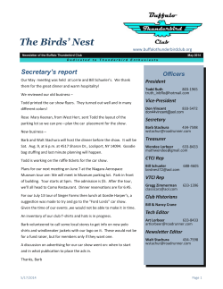


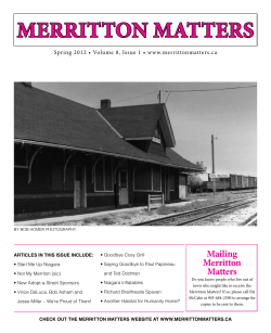

© Copyright 2026