
Anchor Fastening Technology Manual Hilti
Anchor Fastening
Technology Manual
Hilti
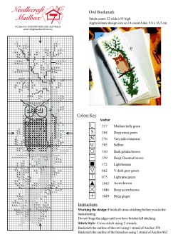
Screw anchor
Steinless steel
HUS-HR
HUS-CR
Size 6 – 14
0
04 / 2014
Version 2014-04
Hilti worldwide
HUS-HR, CR Screw anchor, stainless steel
Anchor version
Benefits
- High productivity – less drilling
and fewer operations than with
conventional anchors
HUS-HR 6 / 8 / 10 / 14
Stainless steel
concrete Screw
with hexagonal head
- ETA approval for cracked and
non-cracked concrete
- Seismic approval ETA C1
HUS-CR 10
Stainless steel
concrete screw
with countersunk head
Concrete
Tensile
zone
Small edge
distance
and spacing
Solid brick
European
Technical
Approval
CE
conformity
Sprinkler
approved
PROFIS
Anchor
design
software
Autoclaved
aerated
concrete
- Small edge and spacing distances
Fire
resistance
Corrosion
Resistance
Seismic
Approvals / certificates
Description
a)
European technical approval
Fire test report
Fire test report ZTV – Tunnel (EBA)
Authority / Laboratory
DIBt, Berlin
DIBt, Berlin
MFPA, Leipzig
No, / date of issue
ETA-08/0307 / 2014-04-29
ETA-08/0307 / 2014-04-29
PB III / 08-354 / 2008-11-27
a) Data for HUS-HR with standard and reduced embedment depth is given in this section according ETA-08/0307
issue 2014-04-29,
Basic loading data
All data in this section applies to
- Correct setting (See setting instruction)
- No edge distance and spacing influence
- Concrete as specified in the table
- Steel failure
- Minimum base material thickness
- Concrete C 20/25, fck,cube = 25 N/mm²
04 / 2014
For details see Simplified design method
1
Mean ultimate resistance
Non-cracked concrete
Anchor size
Type
HUS
Cracked concrete
6
8
10
14
6
8
10
14
HR
HR
HR,CR
HR
HR
HR
HR,CR
HR
50
60
-
30
50
60
-
-
-
a)
6,7
10,0
-
-
a)
22,5
30,0
-
Extra reduced embedment (Hilti Tech Data)
hnom
Tensile NRu,m
Shear VRu,m
[mm]
[kN]
[kN]
30
-
a)
-
a)
12,0
16,0
31,5
41,9
-
Reduced embedment (ETA-08/0307)
hnom
[mm]
-
60
70
70
-
60
70
70
Tensile NRu,m
[kN]
-
16,0
21,3
25,2
-
8,0
12,0
16,0
Shear VRu,m
[kN]
-
34,7
44,0
50,4
-
30,9
38,1
36,0
Standard embedment (ETA-08/0307)
hnom
[mm]
55
80
90
110
55
80
90
110
Tensile NRu,m
[kN]
12,0
21,3
33,3
53,6
6,7
16,0
21,3
33,3
Shear VRu,m
[kN]
22,7
34,7
44,0
102,7
21,7
34,7
44,0
76,6
a) Please refer to resistance table in all load directions for multiple use fastenings in section HUS 6 screw anchor
for redundant fastening,
Characteristic resistance
Non-cracked concrete
Anchor size
Type
HUS
Cracked concrete
6
8
10
14
6
8
10
14
HR
HR
HR,CR
HR
HR
HR
HR,CR
HR
50
60
-
30
50
60
-
-
-
a)
5,0
7,5
-
-
a)
16,9
22,5
-
Extra reduced embedment (Hilti Tech Data)
hnom
Tensile NRk
Shear VRk
[mm]
[kN]
[kN]
30
-
a)
-
a)
9,0
12,0
23,6
31,4
-
Reduced embedment (ETA-08/0307)
hnom
[mm]
-
60
70
70
-
60
70
70
Tensile NRk
[kN]
-
12,0
16,0
18,9
-
6,0
9,0
12,0
Shear VRk
[kN]
-
26,0
33,0
37,8
-
23,2
28,6
27,0
Standard embedment (ETA-08/0307)
hnom
[mm]
55
80
90
110
55
80
90
110
Tensile NRk
[kN]
9,0
16,0
25,0
40,2
5,0
12,0
16,0
25,0
Shear VRk
[kN]
17,0
26,0
33,0
77,0
16,3
26,0
33,0
57,4
a) Please refer to resistance table in all load directions for multiple use fastenings in section HUS 6 screw anchor
for redundant fastening,
Design resistance
Non-cracked concrete
Anchor size
Type
HUS
Cracked concrete
6
8
10
14
6
8
10
14
HR
HR
HR,CR
HR
HR
HR
HR,CR
HR
50
60
-
30
50
60
-
-
-
a)
2,8
4,2
-
-
a)
11,2
15,0
-
Extra reduced embedment (Hilti Tech Data)
hnom
Tensile NRd
Shear VRd
2
[mm]
[kN]
[kN]
30
-
a)
-
a)
5,0
15,7
6,7
21,0
-
04 / 2014
Hilti worldwide
Reduced embedment (ETA-08/0307)
hnom
[mm]
-
60
70
70
-
60
70
70
Tensile NRd
[kN]
-
6,7
8,9
10,5
-
3,3
5,0
6,7
Shear VRd
[kN]
-
17,3
22,0
25,2
-
15,5
19,0
18,0
Standard embedment (ETA-08/0307)
hnom
[mm]
55
80
90
110
55
80
90
110
Tensile NRd
[kN]
4,3
8,9
13,9
22,3
2,4
6,7
8,9
13,9
Shear VRd
[kN]
11,3
17,3
22,0
51,3
10,9
17,3
22,0
38,3
a) Please refer to resistance table in all load directions for multiple use fastenings in section HUS 6 screw anchor
for redundant fastening,
Recommended loads
Non-cracked concrete
Anchor size
Type
HUS
Cracked concrete
6
8
10
14
6
8
10
14
HR
HR
HR,CR
HR
HR
HR
HR,CR
HR
50
60
-
30
50
60
-
-
-
b)
2,0
3,0
-
-
b)
8,0
10,7
-
Extra reduced embedment (Hilti Tech Data)
hnom
[mm]
Tensile Nrec
Shear Vrec
a)
a)
[kN]
[kN]
30
-
b)
-
b)
3,6
4,8
11,2
15,0
-
Reduced embedment (ETA-08/0307)
hnom
Tensile Nrec
Shear Vrec
a)
a)
[mm]
-
60
70
70
-
60
70
70
[kN]
-
4,8
6,3
7,5
-
2,4
3,6
4,8
[kN]
-
12,4
15,7
18,0
-
11,0
13,6
12,9
[mm]
55
80
90
110
55
80
90
110
[kN]
3,1
6,3
9,9
16,0
1,7
4,8
6,3
9,9
[kN]
8,1
12,4
15,7
36,7
7,8
12,4
15,7
27,3
Standard embedment (ETA-08/0307)
hnom
Tensile Nrec
Shear Vrec
a)
a)
a) With overall partial safety factor for action = 1,4, The partial safety factors for action depend on the type of
loading and shall be taken from national regulations,
b) Please refer to resistance table in all load directions for multiple use fastenings in section HUS 6 screw anchor
for redundant fastening,
04 / 2014
3
Materials
Mechanical properties
Anchor size
Type
6
HUS-HR
8
HUS-HR
10
HUS-HR,CR
14
HUS-HR
Nominal tensile strength fuk [N/mm²]
1050
870
950
690
Nominal yield strength fyk
[N/mm²]
900
745
815
590
Stressed cross-section As
[mm²]
22,9
39,0
55,4
143,1
Moment of resistance W
[mm³]
15
34
58
255
Design bending resistance
MRd,s
[Nm]
19
36
66
193
Part
Stainless steel hexagonal head
concrete screw
Material
Stainless steel (grade A4)
Anchor dimensions
Dimensions
Anchor version
ds
[mm]
dk
[mm]
As
2
[mm ]
HUS-HR 6
7,6
5,4
22,9
HUS-HR 8
10,1
7,05
39,0
HUS-HR 10
12,3
8,40
55,4
HUS-CR 10
12,3
8,40
55,4
HUS-HR 14
16,6
12,6
143,1
4
04 / 2014
Hilti worldwide
Screw length and thickness of fixture for HUS-HR (hex head)
Anchor size
6
HUS HR
Nominal anchorage depth
[mm]
Length of anchor [mm]
35
45
60
65
70
75
80
85
95
105
115
120
130
135
8
hnom
30
hnom
55
hnom
50
tfix1
tfix2
tfix1
5
15
30
40
-
5
15
-
15
25
35
45
55
-
10
hnom
hnom
hnom
hnom
60
80
60
70
Thickness of fixture [mm]
tfix2
tfix3
tfix1
tfix2
5
15
25
35
45
-
5
15
25
-
5
15
25
35
45
55
70
-
5
15
25
35
45
60
-
14
hnom
90
hnom
70
hnom
110
tfix3
tfix1
tfix2
5
15
25
40
-
10
50
65
10
25
Screw length and thickness of fixture for HUS-CR (countersunk head)
Anchor size
Nominal anchorage depth
[mm]
Length of anchor [mm]
75
85
105
04 / 2014
10
HUS HR
hnom
60
hnom
70
hnom
90
Thickness of fixture [mm]
tfix1
tfix2
tfix3
15
25
45
15
35
15
5
Setting
Recommended installation equipment
Anchor size
HUS
Rotary hammer
drill bit
Socket wrench insert
Torx (CR type only)
Impact screw driver
6
Hilti TE 2 – TE 30
TE-C3X 6/17
S-NSD 13 ½ (L)
Hilti SIW 14-A, 22-A
8
Hilti TE 2 – TE 30
TE-C3X 8/17
S-NSD 13 ½ (L)
-
10
Hilti TE 2 – TE 30
TE-C3X 10/22
S-NSD 15 ½ (L)
S-SY TX50
Hilti SIW 22 T-A
14
Hilti TE 2 – TE 30
TE-C3X 14/22
S-NSD 21 ½
-
Setting instruction
For detailed information on installation see instruction for use given with the package of the product,
Setting details: depth of drill hole h1 and effective anchorage depth hef
6
04 / 2014
Hilti worldwide
Setting details
Anchor version
6
Type
HUS
8
HR
30
10
HR
55
50
60
14
HR, CR
80
60
70
a)
90
HR
70
110
Nominal embedment depth
hnom
[mm]
Nominal diameter of drill bit
do
[mm]
6
8
10
14
Cutting diameter of drill bit
dcut ≤
[mm]
6,4
8,45
10,45
14,5
Depth of drill hole
h1 ≥
[mm]
Diameter of countersunk head
dh
[mm]
-
-
21
-
Diameter of clearance hole in the
fixture
df ≤
[mm]
9
12
14
18
Effective anchorage depth
hef
[mm]
23
45
38
47
64
Concrete
Tinst
[Nm]
20
- a)
35
- a)
- a)
Solid m, Mz 12
Tinst
[Nm]
- b)
10
- b)
16
16
-
20
20
- b)
- b)
Solid m, KS 12
Tinst
[Nm]
- b)
10
- b)
16
16
-
20
20
- b)
- b)
- b)
4
- b)
Aerated conc,
Tinst
[Nm]
a) Hilti recommends machine setting only in concrete
b) Hilti does not recommend this setting process for this application,
c) Intallation torque refer to HUS-HR only
8
8
-
10
10
- b)
- b)
Max,
installation
torque
40
65
60
70
90
70
46
80
100
54
71
80
120
52
45 c)
86
65
Base material thickness, anchor spacing and edge distance
Anchor size
Type
6
8
10
14
HUS-HR
HUS-HR
HUS-HR, CR
HUS-HR
Nominal embedment
hnom
depth
[mm]
30
55
50
60
80
60
70
90
70
110
Minimum base
material thickness
hmin
non-cracked concrete
[mm]
100
100
100
100
120
120
120
140
140
160
Minimum spacing
smin
[mm]
35
35
45
45
50
50
50
50
50
60
cmin
[mm]
35
35
45
45
50
50
50
50
50
60
scr,N =
scr,sp
[mm]
69
135
114
141
192
166
194
256
187
310
ccr,N =
ccr,sp
[mm]
35
68
57
71
96
83
97
128
94
155
Minimum edge
distance
Critical spacing for
concrete cone and
splitting failure
Critical edge distance
for concrete cone
and splitting failure
For spacing (edge distance) smaller than critical spacing (critical edge distance) the design loads have to be
reduced (see system design resistance),
Critical spacing and critical edge distance for splitting failure apply only for non-cracked concrete, For cracked
concrete only the critical spacing and critical edge distance for concrete cone failure are decisive,
04 / 2014
7
Simplified design method
Simplified version of the design method according ETAG 001, Annex C, Design resistance according data given in
ETA-08/0307 issue 2011,01,21,
Influence of concrete strength
Influence of edge distance
Influence of spacing
Valid for a group of two anchors, (The method may also be applied for anchor groups with more than two
anchors or more than one edge, The influencing factors must then be considered for each edge distance
and spacing, The calculated design loads are then on the save side: They will be lower than the exact
values according ETAG 001, Annex C, To avoid this, it is recommended to use the anchor design software
PROFIS anchor)
The design method is based on the following simplification:
No different loads are acting on individual anchors (no eccentricity)
The values are valid for one anchor (single point fastening), multiple use applications are not part of this design
method,
For more complex fastening applications please use the anchor design software PROFIS Anchor,
TENSION loading
The design tensile resistance is the lower value of
- Steel resistance:
NRd,s
- Concrete pull-out resistance:
NRd,p = N
0
Rd,p
fB
- Concrete cone resistance:
NRd,c = N
0
Rd,c
fB f1,N f2,N f3,N fre,N
NRd,sp = N
0
Rd,c
fB f1,sp f2,sp f3,sp fre,N
Concrete splitting resistance
(only non-cracked concrete):
-
Basic design tensile resistance
Design steel resistance NRd,s
Anchor size
Type
NRd,s
6
8
10
14
HUS-HR
HUS-HR
HUS-HR, CR
HUS-HR
17,0
24,3
37,6
73,0
[kN]
Design pull-out resistance NRd,p = N0Rd,p fB
Non-cracked concrete
Anchor size
Cracked concrete
6
8
10
14
6
8
10
14
Extra reduced embedment
(Hilti Tech Data)
hnom
[mm]
30
50
60
-
30
50
60
-
Tensile NRd
[kN]
-
5,0
6,7
-
-
2,8
4,2
-
hnom
[mm]
-
60
70
70
-
60
70
70
Tensile NRd
[kN]
-
6,7
8,9
10,5
-
3,3
5,0
6,7
hnom
[mm]
55
80
90
110
55
80
90
110
Tensile NRd
[kN]
4,3
8,9
13,9
22,3
2,4
6,7
8,9
13,9
Reduced embedment
Standard embedment
8
04 / 2014
Hilti worldwide
Design concrete cone NRd,c = N0Rd,c fB f1,N f2,N f3,N fre,N
Design splitting resistance* NRd,sp = N0Rd,c fB f1,sp f2,sp f3,sp fre,N
Non-cracked concrete
Anchor size
Type
HUS
Cracked concrete
6
8
10
14
6
8
10
14
HR
HR
HR,CR
HR
HR
HR
HR,CR
HR
50
60
-
30
50
60
-
6,6
8,7
Reduced embedment
60
70
70
-
4,7
6,2
-
-
60
70
70
9,0
11,1
10,5
Standard embedment
80
90
110
-
6,4
7,9
7,5
55
80
90
110
5,2
10,2
12,0
16,0
Extra reduced embedment (Hilti Tech Data)
hnom
[mm]
30
0
N Rd,c
[kN]
-
hnom
[mm]
-
0
N Rd,c
[kN]
-
hnom
[mm]
55
0
N Rd,c
[kN]
7,2
14,3
16,8
22,3
a) Splitting resistance must only be considered for non-cracked concrete
ETA: Data according ETA-08/0307 issue 2008-12-12
Hilti: Additional Hilti technical data
Influencing factors
Influence of concrete strength
Concrete strength designation
(ENV 206)
C 20/25
C 25/30
C 30/37
C 35/45
C 40/50
0,5 a)
fB =
(fck,cube/25N/mm²)
1
1,1
1,22
1,34
1,41
a) fck,cube = concrete compressive strength, measured on cubes with 150 mm side length
C 45/55
C 50/60
1,48
1,55
Influence of edge distance a)
c/ccr,N
c/ccr,sp
f1,N =
0,7 + 0,3c/ccr,N ≤ 1
f1,sp = 0,7 + 0,3c/ccr,sp ≤ 1
f2,N =
0,1
0,2
0,3
0,4
0,5
0,6
0,7
0,8
0,9
1
0,73
0,76
0,79
0,82
0,85
0,88
0,91
0,94
0,97
1
0,5(1 + c/ccr,N) ≤ 1
0,55 0,60 0,65 0,70 0,75 0,80 0,85 0,90 0,95
1
f2,sp = 0,5(1 + c/ccr,sp) ≤ 1
a) The edge distance shall not be smaller than the minimum edge distance cmin given in the table with the setting
details, These influencing factors must be considered for every edge distance,
Influence of anchor spacing a)
s/scr,N
0,1
s/scr,sp
f3,N =
0,2
0,3
0,4
0,5
0,6
0,7
0,8
0,9
1
0,5(1 + s/scr,N) ≤ 1
0,55 0,60 0,65 0,70 0,75 0,80 0,85 0,90 0,95
1
f3,sp = 0,5(1 + s/scr,sp) ≤ 1
a) The anchor spacing shall not be smaller than the minimum anchor spacing s min given in the table with the
setting details, This influencing factor must be considered for every anchor spacing,
04 / 2014
9
Influence of base material thickness
h/hef
2/3
f h,sp = [h/(2hef)]
2,0
2,2
2,4
2,6
2,8
3,0
3,2
3,4
3,6
≥ 3,68
1
1,07
1,13
1,19
1,25
1,31
1,37
1,42
1,48
1,5
Influence of reinforcement
Anchor size
Type
6
HR
8
HR
10
HR, CR
14
HR
HUS
hnom
[mm]
30
55
50
60
80
60
70
90
70
110
hef
[mm]
23
45
38
47
64
46
54
71
52
86
0,62 0,73 0,69 0,74 0,82 0,73 0,77 0,86 0,76 0,93
fre,N = 0,5 + hef/200mm ≤ 1
a) This factor applies only for dense reinforcement, If in the area of anchorage there is reinforcement with a
spacing ≥ 150 mm (any diameter) or with a diameter ≤ 10 mm and a spacing ≥ 100 mm, then a factor fre,N = 1
may be applied,
SHEAR loading
The design shear resistance is the lower value of
- Steel resistance:
-
VRd,s
Concrete pryout resistance:
- Concrete edge resistance:
VRd,cp = k NRd,c
VRd,c = V
0
Rd,c
fB fß f h f4 f hef fc
Basic design shear resistance
Design steel resistance VRd,s
Anchor size
Type
HUS
6
HR
8
HR
10
HR, CR
14
HR
Extra reduced
embedment
VRd,s
[kN]
11,3
17,3
22,0
-
Reduced
embedment
VRd,s
[kN]
-
17,3
22,0
36,7
Standard
embedment
VRd,s
[kN]
11,3
17,3
22,0
51,3
Design concrete pryout resistance VRd,cp = k NRd,ca)
Anchor size
Type
HUS
hnom
[mm]
k
a)
10
6
HR
8
HR
30
55
1,0
NRd,c: Design concrete cone resistance
1,5
50
60
10
HR, CR
80
60
70
14
HR
90
70
110
2,0
04 / 2014
Hilti worldwide
Design concrete edge resistance VRd,c = V0Rd,c fB fß f h f4 f hef fc
Non-cracked concrete
Anchor size
Type
HUS
Cracked concrete
6
8
10
14
6
8
10
14
HR
HR
HR,CR
HR
HR
HR
HR,CR
HR
Extra reduced embedment (Hilti Tech Data)
hnom
[mm]
30
50
60
-
30
50
60
-
0
V Rd,c
[kN]
-
5,9
8,6
-
-
4,2
6,1
-
hnom
[mm]
-
60
70
70
-
60
70
70
0
V Rd,c
[kN]
-
5,9
8,6
15
-
4,2
6,1
10,6
hnom
[mm]
55
80
90
110
55
80
90
110
0
V Rd,c
[kN]
3,6
5,9
8,6
15,1
2,6
4,2
6,1
10,7
C 45/55
C 50/60
1,48
1,55
Reduced embedment
Standard embedment
Influencing factors
Influence of concrete strength
Concrete strength designation
(ENV 206)
C 20/25
C 25/30
C 30/37
C 35/45
C 40/50
0,5 a)
fB =
(fck,cube/25N/mm²)
1
1,1
1,22
1,34
1,41
a) fck,cube = concrete compressive strength, measured on cubes with 150 mm side length
Influence of angle between load applied and the direction perpendicular to the free edge
Angle ß
f
0°
10°
20°
30°
40°
50°
60°
70°
80°
≥ 90°
1
1,01
1,05
1,13
1,24
1,40
1,64
1,97
2,32
2,50
0,15
0,3
0,45
0,6
0,75
0,9
1,05
1,2
1,35
≥ 1,5
0,32
0,45
0,55
0,63
0,71
0,77
0,84
0,89
0,95
1,00
1
cos V 2 sin V
2
2,5
Influence of base material thickness
h/c
fh =
04 / 2014
{h/(1,5 c)}
1/2
≤1
11
Influence of anchor spacing and edge distance a) for concrete edge resistance: f4
Group of two anchors s/hef
Single
anchor 0,75 1,50 2,25 3,00 3,75 4,50 5,25 6,00 6,75 7,50 8,25 9,00 9,75 10,50 11,25
0,50
0,35
0,27 0,35 0,35 0,35 0,35 0,35 0,35 0,35 0,35 0,35 0,35 0,35 0,35 0,35 0,35
0,75
0,65
0,43 0,54 0,65 0,65 0,65 0,65 0,65 0,65 0,65 0,65 0,65 0,65 0,65 0,65 0,65
1,00
1,00
0,63 0,75 0,88 1,00 1,00 1,00 1,00 1,00 1,00 1,00 1,00 1,00 1,00 1,00 1,00
1,25
1,40
0,84 0,98 1,12 1,26 1,40 1,40 1,40 1,40 1,40 1,40 1,40 1,40 1,40 1,40 1,40
1,50
1,84
1,07 1,22 1,38 1,53 1,68 1,84 1,84 1,84 1,84 1,84 1,84 1,84 1,84 1,84 1,84
1,75
2,32
1,32 1,49 1,65 1,82 1,98 2,15 2,32 2,32 2,32 2,32 2,32 2,32 2,32 2,32 2,32
2,00
2,83
1,59 1,77 1,94 2,12 2,30 2,47 2,65 2,83 2,83 2,83 2,83 2,83 2,83 2,83 2,83
2,25
3,38
1,88 2,06 2,25 2,44 2,63 2,81 3,00 3,19 3,38 3,38 3,38 3,38 3,38 3,38 3,38
2,50
3,95
2,17 2,37 2,57 2,77 2,96 3,16 3,36 3,56 3,76 3,95 3,95 3,95 3,95 3,95 3,95
2,75
4,56
2,49 2,69 2,90 3,11 3,32 3,52 3,73 3,94 4,15 4,35 4,56 4,56 4,56 4,56 4,56
3,00
5,20
2,81 3,03 3,25 3,46 3,68 3,90 4,11 4,33 4,55 4,76 4,98 5,20 5,20 5,20 5,20
3,25
5,86
3,15 3,38 3,61 3,83 4,06 4,28 4,51 4,73 4,96 5,18 5,41 5,63 5,86 5,86 5,86
3,50
6,55
3,51 3,74 3,98 4,21 4,44 4,68 4,91 5,14 5,38 5,61 5,85 6,08 6,31 6,55 6,55
3,75
7,26
3,87 4,12 4,36 4,60 4,84 5,08 5,33 5,57 5,81 6,05 6,29 6,54 6,78 7,02 7,26
4,00
8,00
4,25 4,50 4,75 5,00 5,25 5,50 5,75 6,00 6,25 6,50 6,75 7,00 7,25 7,50 7,75
4,25
8,76
4,64 4,90 5,15 5,41 5,67 5,93 6,18 6,44 6,70 6,96 7,22 7,47 7,73 7,99 8,25
4,50
9,55
5,04 5,30 5,57 5,83 6,10 6,36 6,63 6,89 7,16 7,42 7,69 7,95 8,22 8,49 8,75
4,75
10,35 5,45 5,72 5,99 6,27 6,54 6,81 7,08 7,36 7,63 7,90 8,17 8,45 8,72 8,99 9,26
5,00
11,18 5,87 6,15 6,43 6,71 6,99 7,27 7,55 7,83 8,11 8,39 8,66 8,94 9,22 9,50 9,78
5,25
12,03 6,30 6,59 6,87 7,16 7,45 7,73 8,02 8,31 8,59 8,88 9,17 9,45 9,74 10,02 10,31
5,50
12,90 6,74 7,04 7,33 7,62 7,92 8,21 8,50 8,79 9,09 9,38 9,67 9,97 10,26 10,55 10,85
a) The anchor spacing and the edge distance shall not be smaller than the minimum anchor spacing s min and the
minimum edge distance cmin,
c/hef
Influence of embedment depth
Anchor size
Type
hnom
f hef =
6
HR
HUS
[mm]
0,05 (hef / d)
1,68
8
HR
10
HR, CR
14
HR
30
55
50
60
80
60
70
90
70
110
-
1,48
0,69
0,98
1,64
0,65
0,85
1,35
0,45
1,06
Influence of edge distance a)
c/d
4
6
8
0,19
10
15
0,77
0,71
0,67
0,65
0,60
fc =
(d / c)
a) The edge distance shall not be smaller than the minimum edge distance cmin,
20
30
40
0,57
0,52
0,50
Combined TENSION and SHEAR loading
For combined tension and shear loading see section “Anchor Design”,
Precalculated values
Design resistance calculated according ETAG 001, Annex C and data given in ETA-08/0307, issue 2011,01,21,
All data applies to concrete C 20/25 – fck,cube =25 N/mm², Hilti technical data for the extra reduced embedment
depth is not part of the approval,
Recommended loads can be calculated by dividing the design resistance by an overall partial safety factor for
action = 1,4, The partial safety factors for action depend on the type of loading and shall be taken from national
regulations,
12
04 / 2014
Hilti worldwide
Design resistance
Single anchor, no edge effects (c ≥ ccr), shear without lever arm
Non-cracked concrete
Anchor size
Type
HUS
Cracked concrete
6
8
10
14
6
8
10
14
HR
HR
HR,CR
HR
HR
HR
HR,CR
HR
Extra reduced embedment (Hilti Tech Data)
[mm]
30
50
60
-
30
50
60
-
Min, base material thickness hmin [mm]
80
100
120
-
80
100
120
-
hnom
Tensile NRd
[kN]
-
5,0
6,7
-
-
2,8
4,2
-
Shear VRd
[kN]
-
15,7
21,0
-
-
11,2
15,0
-
[mm]
-
60
70
70
-
60
70
70
Min, base material thickness hmin [mm]
-
100
120
140
-
100
120
140
Reduced embedment
hnom
Tensile NRd
[kN]
-
6,7
8,9
10,5
-
3,3
5,0
6,7
Shear VRd
[kN]
-
17,3
22,0
25,2
-
15,5
19,0
18,0
Standard embedment
[mm]
55
80
90
110
55
80
90
110
Min, base material thickness hmin [mm]
100
120
140
160
100
120
140
160
hnom
04 / 2014
Tensile NRd
[kN]
4,3
8,9
13,9
22,3
2,4
6,7
8,9
13,9
Shear VRd
[kN]
11,3
17,3
22,0
51,3
10,9
17,3
22,0
38,3
13
Single anchor, min, edge distance (c = cmin), shear without lever arm
Non-cracked concrete
Anchor size
Type
HUS
Cracked concrete
6
8
10
14
6
8
10
14
HR
HR
HR,CR
HR
HR
HR
HR,CR
HR
Extra reduced embedment (Hilti Tech Data)
[mm]
30
50
60
-
30
50
60
-
Min, base material thickness hmin [mm]
Min, edge distance cmin [mm]
80
40
100
45
120
50
-
80
40
100
45
120
50
-
hnom
Tensile NRd
[kN]
-
5,0
6,7
-
-
2,8
4,2
-
Shear VRd
[kN]
-
3,8
4,7
-
-
2,7
3,3
-
[mm]
-
60
70
70
-
60
70
70
Min, base material thickness hmin [mm]
Min, edge distance cmin [mm]
-
100
45
120
50
140
50
-
100
45
120
50
140
50
Reduced embedment
hnom
Tensile NRd
[kN]
-
6,6
8,0
7,7
-
3,3
5,0
4,9
Shear VRd
[kN]
-
3,9
4,8
5,0
-
2,8
3,4
3,6
[mm]
55
80
90
110
55
80
90
110
Min, base material thickness hmin [mm]
Min, edge distance cmin [mm]
100
40
120
50
140
50
160
60
100
40
120
50
140
50
160
60
Standard embedment
hnom
14
Tensile NRd
[kN]
4,3
8,9
10,4
13,8
2,4
6,7
6,8
9,0
Shear VRd
[kN]
3,2
4,8
5,1
7,1
2,2
3,4
3,6
5,0
04 / 2014
Hilti worldwide
Double anchor, no edge effects (c ≥ ccr), min, spacing (s = smin), shear without lever arm
(load values are valid for one anchor)
Non-cracked concrete
Anchor size
Type
HUS
Cracked concrete
6
8
10
14
6
8
10
14
HR
HR
HR,CR
HR
HR
HR
HR,CR
HR
Extra reduced embedment (Hilti Tech Data)
[mm]
30
50
60
-
30
50
60
-
Min, base material thickness hmin [mm]
Min, spacing smin [mm]
80
40
100
45
120
50
-
80
40
100
45
120
50
-
hnom
Tensile NRd
[kN]
-
4,6
6,0
-
-
3,3
4,3
-
Shear VRd
[kN]
-
11,0
14,3
-
-
7,8
10,2
-
[mm]
-
60
70
70
-
60
70
70
Min, base material thickness hmin [mm]
Min, spacing smin [mm]
-
100
45
120
50
140
50
-
100
45
120
50
140
50
Reduced embedment
hnom
Tensile NRd
[kN]
-
6,0
7,3
6,9
-
4,3
5,2
5,0
Shear VRd
[kN]
-
14,3
17,5
16,7
-
10,2
12,5
11,9
[mm]
55
80
90
110
55
80
90
110
Min, base material thickness hmin [mm]
Min, spacing smin [mm]
100
40
120
50
140
50
160
60
100
40
120
50
140
50
160
60
Standard embedment
hnom
04 / 2014
Tensile NRd
[kN]
4,7
9,1
10,4
13,8
3,4
6,5
7,4
9,8
Shear VRd
[kN]
9,9
17,3
22,0
33,1
7,0
15,5
17,7
23,6
15
Fire resistance
Basic loading data for concrete C20/25 – C50/60
All data in this section applies to:
- Correct setting (see setting instruction)
- No edge distance and spacing influence
- Minimum base material thickness
The following technical data are based on:
ETA-08/0307 issue 2014-04-29
Characteristic loads under fire exposure
Anchor Size
Type
HUS
Nominal embedment
depth
hnom
[mm]
6
8
10
14
HR
HR
HR, CR
HR, CR
hnom
hnom
hnom
hnom
hnom
hnom
hnom
50
60
80
70
90
70
110
Steel failure for tension and shear load (FRec,s,fi = NRec,s,fi = VRec,s,fi)
R30
FRec,s,fi
[kN]
2,3
4,4
8,8
19,9
R60
FRec,s,fi
[kN]
1,6
3,0
5,7
12,8
R90
FRec,s,fi
[kN]
0,9
1,5
2,6
5,8
R120
FRec,s,fi
[kN]
0,5
0,8
1,1
2,6
R30
0
M Rec,s,fi
[Nm]
1,9
3,9
9,2
31,2
R60
0
M Rec,s,fi
[Nm]
1,3
2,6
6,0
20,2
R90
0
M Rec,s,fi
[Nm]
0,7
1,3
2,7
9,1
R120
0
M Rec,s,fi
[Nm]
0,4
0,7
1,2
4,0
R30
R60
R90
NRec,p,fi
[kN]
0,6
0,7
1,4
1,1
1,9
1,4
3,0
R120
NRec,p,fi
[kN]
0,5
0,6
1,1
0,9
1,5
1,1
2,4
R30 to R120
ccr,N
[mm]
2hef
R30 to R120
scr,N
[mm]
4hef
k
[-]
Recommended
tensile and
shear load
Pull out failure
Recommended
resistance
Concrete cone failure
Edge distance
Spacing
Concrete pry-out failure
R30 to R120
1,5
2,0
2,0
2,0
a) gThe recommended loads under fire exposure include a safety factor for resistance under fire exposure M,fi = 1,0 and the partial
safety factor for action F,fi = 1,0, The partial safety factors for action shall be taken from national regulations,
16
04 / 2014
Hilti worldwide
Seismic design
Basic loading data for concrete C20/25 – C50/60
All data in this section applies to:
- Seismic design according to TR045
The following technical data are based on:
ETA-08/0307 issue 2014-04-30
Anchorage depth range
Anchor size
8
10
14
HUS
HR
HR, CR
HR
[mm]
80
90
110
8
10
14
HUS
HR
HR, CR
HR
Characteristic tension resistance to steel failure
NRk,s,seis
[kN]
34,0
52,6
102,2
Type
Nominal anchorage depth range
hnom
Tension resistance in case of seismic performance category C1
Anchor size
Type
Partial safety factor
Ms,seis
[-]
1,4
Characteristic pull-out resistance in cracked concrete C20/25 to C50/60
7,7
NRk,p,seis [kN]
Partial safety factor
[-]
Mp,seis
12,5
1,8
Concrete cone resistance and splitting resistance
Partial safety factor
[-]
Mc,seis = Msp,seis
1,8
Displacement under tension load in case of seismic performance category C1
Anchor size
17,5
1)
8
10
14
HR
HR, CR
HR
1,2
1,2
0,4
8
10
14
HUS
HR
HR, CR
HR
Characteristic shear resistance to steel failure
VRk,s,seis
[kN]
Partial safety factor
[-]
Ms,seis
11,1
17,9
1,5
53,9
Type
HUS
Displacement
[mm]
N,seis
1) Maximum displacement during cycling (seismic event),
Shear resistance in case of seismic performance category C1
Anchor size
Type
Concrete pryout resistance and concrete edge resistance
Partial safety factor
[-]
Mc,seis
1) Reduction factor gap = 1,0 when using the Hilti Dynamic Set
1)
1,5
Displacement under tension load in case of seismic performance category C1
Anchor size
Type
HUS
Displacement
[mm]
V,seis
1) Maximum displacement during cycling (seismic event)
04 / 2014
1)
8
10
14
HR
HR, CR
HR
4,8
5,3
7,6
17
Basic loading data for single anchor in solid masonry units
All data in this section applies to
- Load values valid for holes drilled with TE rotary hammers in hammering mod
- Correct anchor setting (see instruction for use, setting details)
- The core / material ratio may not exceed 15% of a bed joint area,
- The brim area around holes must be at least 70mm
- Edge distances, spacing and other influences, see below
Recommended loads
Hilti
Base material
Anchor size
Type
Solid sand-lime brick
KS 12/2,0
Aerated concrete PPW
6-0,4
a)
18
8
HUS-HR
10
HUS-HR, CR
hnom
[mm]
55
60
70
DIN 105/
EN 771-1
a)
fb 12 N/mm²
Tensile Nrec
[kN]
0,9
1,0
1,1
Shear Vrec
[kN]
1,4
2,0
2,3
DIN 106/
EN 771-2
a)
fb 12 N/mm²
Tensile Nrec
0,6
0,6
1,0
0,9
1,1
1,7
DIN 4165/
EN 771-4
a)
fb 6 N/mm²
Tensile Nrec
0,2
0,2
0,4
0,4
0,4
0,9
Germany, Austria, Switzerland
Solid clay brick
Mz12/2,0
6
HUS-HR
Shear Vrec
Shear Vrec
[kN]
[kN]
[kN]
[kN]
fb = brick strength
04 / 2014
Hilti worldwide
Permissible anchor location in brick and block walls
Edge distance and spacing influences
The technical data for the HUS-HR anchors are reference loads for MZ 12 and KS 12, Due to the large
variation of natural stone solid bricks, on site anchor testing is recommended to validate technical data,
The HUS-HR anchor was installed and tested in center of solid bricks as shown, The HUS-HR anchor was
not tested in the mortar joint between solid bricks or in hollow bricks; however a load reduction is expected,
For brick walls where anchor position in brick can not be determined, 100% anchor testing is recommended,
Distance to free edge free edge to solid masonry (Mz and KS) units ≥ 200 mm
Distance to free edge free edge to solid masonry (autoclaved aerated gas concrete) units ≥ 170 mm
The minimum distance to horizontal and vertical mortar joint (c min) is stated in drawing above,
Minimum anchor spacing (smin) in one brick/block is ≥ 2*cmin
Limits
Applied load to individual bricks may not exceed 1,0 kN without compression or 1,4 kN with compression
All data is for multiple use for non structural applications
Plaster, graveling, lining or levelling courses are regarded as non-bearing and may not be taken into account
for the calculation of embedment depth,
04 / 2014
19


© Copyright 2026