
V2 FM TRANSMITTERS TECHNICAL MANUAL Document rev 3
V2 FM TRANSMITTERS
TECHNICAL MANUAL
Document rev 3
The software in the transmitter is upgradeable. This manual may refer to an older software version. Note that
previous versions of software may not have all of the features described in the manual. To check the latest
software go to www.bwbroadcast.com/downloads
No part of this manual may be re-produced in any form without prior written permission from BW Broadcast. The
information and specifications contained in this document is subject to change at any time without notice.
©2014 BW Broadcast
www.bwbroadcast.com
Contents
I
Introduction
1
The TX-V2 . . . . . . . . . . . . . . . . . . . . . . . . . . . . . . . . . . . . . . . . .
8
2
Warranty . . . . . . . . . . . . . . . . . . . . . . . . . . . . . . . . . . . . . . . . .
9
3
Safety . . . . . . . . . . . . . . . . . . . . . . . . . . . . . . . . . . . . . . . . . . .
11
4
Front and Rear Panels . . . . . . . . . . . . . . . . . . . . . . . . . . . . . . . . . .
15
5
4.1
1U (TX5, TX50) . . . . . . . . . . . . . . . . . . . . . . . . . . . . . . . . . . . .
15
4.2
2U (TX300, TX600) . . . . . . . . . . . . . . . . . . . . . . . . . . . . . . . . . .
16
4.3
2U (TX1000, TX1500) . . . . . . . . . . . . . . . . . . . . . . . . . . . . . . . . .
17
User Interface
5.1
5.2
II
7
. . . . . . . . . . . . . . . . . . . . . . . . . . . . . . . . . . . . . .
18
Input Interface . . . . . . . . . . . . . . . . . . . . . . . . . . . . . . . . . . .
18
5.1.1 Navigating the menu . . . . . . . . . . . . . . . . . . . . . . . . . . . . .
18
5.1.2 Editing a parameter
. . . . . . . . . . . . . . . . . . . . . . . . . . . . .
18
5.1.3 Text fields . . . . . . . . . . . . . . . . . . . . . . . . . . . . . . . . . . . .
18
Display . . . . . . . . . . . . . . . . . . . . . . . . . . . . . . . . . . . . . . . .
19
5.2.1 Status Box . . . . . . . . . . . . . . . . . . . . . . . . . . . . . . . . . . . .
19
5.2.2 Menu Box . . . . . . . . . . . . . . . . . . . . . . . . . . . . . . . . . . . .
20
5.2.3 Meters . . . . . . . . . . . . . . . . . . . . . . . . . . . . . . . . . . . . . .
21
Initial Setup and connections
22
6
23
Installation . . . . . . . . . . . . . . . . . . . . . . . . . . . . . . . . . . . . . . . .
6.1
Quick Start . . . . . . . . . . . . . . . . . . . . . . . . . . . . . . . . . . . . . .
23
6.2
Examples of Use . . . . . . . . . . . . . . . . . . . . . . . . . . . . . . . . . . .
24
6.2.1 Transmitter with an external RDS encoder and internal audio processing . . . . . . . . . . . . . . . . . . . . . . . . . . . . . . . . . . . . .
24
6.2.2 Transmitter with an external audio processor . . . . . . . . . . . . . . .
25
6.2.3 Transmitter with an external audio processor and RDS (In Line Connection) . . . . . . . . . . . . . . . . . . . . . . . . . . . . . . . . . . . . .
26
6.2.4 Transmitter with an external audio processor and RDS (Side Chain
Connection) . . . . . . . . . . . . . . . . . . . . . . . . . . . . . . . . . .
27
2
III
System Configuration
29
7
30
Operation Guide . . . . . . . . . . . . . . . . . . . . . . . . . . . . . . . . . . . .
7.1
RF Settings . . . . . . . . . . . . . . . . . . . . . . . . . . . . . . . . . . . . . .
30
7.1.1 Basic Setup . . . . . . . . . . . . . . . . . . . . . . . . . . . . . . . . . . .
30
7.1.2 Power Scheduler . . . . . . . . . . . . . . . . . . . . . . . . . . . . . . .
30
7.2
Audio Settings . . . . . . . . . . . . . . . . . . . . . . . . . . . . . . . . . . . .
31
7.3
Triggers . . . . . . . . . . . . . . . . . . . . . . . . . . . . . . . . . . . . . . . .
31
7.4
Alarms . . . . . . . . . . . . . . . . . . . . . . . . . . . . . . . . . . . . . . . .
32
7.5
System . . . . . . . . . . . . . . . . . . . . . . . . . . . . . . . . . . . . . . . .
33
7.5.1 Real Time Clock . . . . . . . . . . . . . . . . . . . . . . . . . . . . . . . .
33
7.5.2 Unit Information . . . . . . . . . . . . . . . . . . . . . . . . . . . . . . . .
33
7.5.3 Screen Saver . . . . . . . . . . . . . . . . . . . . . . . . . . . . . . . . . .
34
7.5.4 Users . . . . . . . . . . . . . . . . . . . . . . . . . . . . . . . . . . . . . . .
34
7.5.5 Ethernet . . . . . . . . . . . . . . . . . . . . . . . . . . . . . . . . . . . . .
34
7.5.6 E-Mail . . . . . . . . . . . . . . . . . . . . . . . . . . . . . . . . . . . . . .
35
7.5.7 HTTP . . . . . . . . . . . . . . . . . . . . . . . . . . . . . . . . . . . . . . .
36
7.5.8 Telnet . . . . . . . . . . . . . . . . . . . . . . . . . . . . . . . . . . . . . .
36
7.5.9 RS232 . . . . . . . . . . . . . . . . . . . . . . . . . . . . . . . . . . . . . .
37
7.5.10 Log . . . . . . . . . . . . . . . . . . . . . . . . . . . . . . . . . . . . . . . .
37
7.5.11 Diagnostics . . . . . . . . . . . . . . . . . . . . . . . . . . . . . . . . . . .
39
7.5.12 About . . . . . . . . . . . . . . . . . . . . . . . . . . . . . . . . . . . . . .
39
7.5.13 Reboot . . . . . . . . . . . . . . . . . . . . . . . . . . . . . . . . . . . . .
39
7.5.14 Factory Reset . . . . . . . . . . . . . . . . . . . . . . . . . . . . . . . . . .
39
Web Remote . . . . . . . . . . . . . . . . . . . . . . . . . . . . . . . . . . . .
39
7.6.1 Autentication . . . . . . . . . . . . . . . . . . . . . . . . . . . . . . . . .
39
7.6.2 Web Remote Interface . . . . . . . . . . . . . . . . . . . . . . . . . . . .
40
Text Based Access (Telnet or Serial RS232) . . . . . . . . . . . . . . . . . . .
42
7.7.1 Commands . . . . . . . . . . . . . . . . . . . . . . . . . . . . . . . . . . .
42
7.6
7.7
3
7.8
Web API . . . . . . . . . . . . . . . . . . . . . . . . . . . . . . . . . . . . . . .
43
7.8.1 Authentication . . . . . . . . . . . . . . . . . . . . . . . . . . . . . . . . .
44
7.8.2 Setting A Parameter . . . . . . . . . . . . . . . . . . . . . . . . . . . . .
44
7.8.3 Reading Parameters . . . . . . . . . . . . . . . . . . . . . . . . . . . . .
45
7.8.4 Reading Meters . . . . . . . . . . . . . . . . . . . . . . . . . . . . . . . .
46
7.8.5 Reading log files . . . . . . . . . . . . . . . . . . . . . . . . . . . . . . . .
46
Parameters . . . . . . . . . . . . . . . . . . . . . . . . . . . . . . . . . . . . .
47
7.9.1 RF Settings . . . . . . . . . . . . . . . . . . . . . . . . . . . . . . . . . . .
47
7.9.2 Audio Settings . . . . . . . . . . . . . . . . . . . . . . . . . . . . . . . . .
49
7.9.3 Triggers . . . . . . . . . . . . . . . . . . . . . . . . . . . . . . . . . . . . .
50
7.9.4 Alarms . . . . . . . . . . . . . . . . . . . . . . . . . . . . . . . . . . . . . .
50
7.9.5 System . . . . . . . . . . . . . . . . . . . . . . . . . . . . . . . . . . . . . .
51
Parameter Guide . . . . . . . . . . . . . . . . . . . . . . . . . . . . . . . . . . . .
59
7.9
8
8.1
8.2
8.3
RF Settings . . . . . . . . . . . . . . . . . . . . . . . . . . . . . . . . . . . . . .
59
8.1.1 Frequency . . . . . . . . . . . . . . . . . . . . . . . . . . . . . . . . . . .
59
8.1.2 Power . . . . . . . . . . . . . . . . . . . . . . . . . . . . . . . . . . . . . .
59
8.1.3 MPX Source . . . . . . . . . . . . . . . . . . . . . . . . . . . . . . . . . . .
59
8.1.4 FSK (for translators in the USA) . . . . . . . . . . . . . . . . . . . . . . . .
60
8.1.5 RF Mute on Silence . . . . . . . . . . . . . . . . . . . . . . . . . . . . . .
60
8.1.6 RF Mute (Manual) . . . . . . . . . . . . . . . . . . . . . . . . . . . . . . .
60
8.1.7 Power Scheduler . . . . . . . . . . . . . . . . . . . . . . . . . . . . . . .
60
Audio Settings . . . . . . . . . . . . . . . . . . . . . . . . . . . . . . . . . . . .
61
8.2.1 MPX Source . . . . . . . . . . . . . . . . . . . . . . . . . . . . . . . . . . .
61
8.2.2 Audio Input . . . . . . . . . . . . . . . . . . . . . . . . . . . . . . . . . . .
61
8.2.3 Processing Preset . . . . . . . . . . . . . . . . . . . . . . . . . . . . . . .
62
8.2.4 Pre-emphasis . . . . . . . . . . . . . . . . . . . . . . . . . . . . . . . . . .
62
Triggers . . . . . . . . . . . . . . . . . . . . . . . . . . . . . . . . . . . . . . . .
62
8.3.1 Enable . . . . . . . . . . . . . . . . . . . . . . . . . . . . . . . . . . . . . .
62
4
8.4
8.5
IV
8.3.2 Action . . . . . . . . . . . . . . . . . . . . . . . . . . . . . . . . . . . . . .
63
8.3.3 Send e-mail . . . . . . . . . . . . . . . . . . . . . . . . . . . . . . . . . . .
63
8.3.4 (ON) Message . . . . . . . . . . . . . . . . . . . . . . . . . . . . . . . . .
63
Alarms . . . . . . . . . . . . . . . . . . . . . . . . . . . . . . . . . . . . . . . .
64
8.4.1 Type . . . . . . . . . . . . . . . . . . . . . . . . . . . . . . . . . . . . . . .
64
System . . . . . . . . . . . . . . . . . . . . . . . . . . . . . . . . . . . . . . . .
67
8.5.1 Date . . . . . . . . . . . . . . . . . . . . . . . . . . . . . . . . . . . . . . .
67
8.5.2 Time . . . . . . . . . . . . . . . . . . . . . . . . . . . . . . . . . . . . . . .
68
8.5.3 Uptime . . . . . . . . . . . . . . . . . . . . . . . . . . . . . . . . . . . . .
68
8.5.4 Location . . . . . . . . . . . . . . . . . . . . . . . . . . . . . . . . . . . .
68
8.5.5 Contact . . . . . . . . . . . . . . . . . . . . . . . . . . . . . . . . . . . . .
68
8.5.6 Screen Saver . . . . . . . . . . . . . . . . . . . . . . . . . . . . . . . . . .
68
8.5.7 Screen Lock . . . . . . . . . . . . . . . . . . . . . . . . . . . . . . . . . .
68
8.5.8 Screen Lock Code . . . . . . . . . . . . . . . . . . . . . . . . . . . . . .
68
8.5.9 Users . . . . . . . . . . . . . . . . . . . . . . . . . . . . . . . . . . . . . . .
68
8.5.10 Ethernet . . . . . . . . . . . . . . . . . . . . . . . . . . . . . . . . . . . . .
69
8.5.11 E-Mail . . . . . . . . . . . . . . . . . . . . . . . . . . . . . . . . . . . . . .
70
8.5.12 HTTP . . . . . . . . . . . . . . . . . . . . . . . . . . . . . . . . . . . . . . .
71
8.5.13 Telnet . . . . . . . . . . . . . . . . . . . . . . . . . . . . . . . . . . . . . .
71
8.5.14 RS232 . . . . . . . . . . . . . . . . . . . . . . . . . . . . . . . . . . . . . .
72
8.5.15 Log . . . . . . . . . . . . . . . . . . . . . . . . . . . . . . . . . . . . . . . .
72
8.5.16 Diagnostics . . . . . . . . . . . . . . . . . . . . . . . . . . . . . . . . . . .
73
8.5.17 About . . . . . . . . . . . . . . . . . . . . . . . . . . . . . . . . . . . . . .
73
8.5.18 Reboot . . . . . . . . . . . . . . . . . . . . . . . . . . . . . . . . . . . . .
74
8.5.19 Factory Reset . . . . . . . . . . . . . . . . . . . . . . . . . . . . . . . . . .
74
Troubleshooting
9
75
V2 FM Transmitter Troubleshooting Guide . . . . . . . . . . . . . . . . . . . . . .
5
76
V
Technical Specifications
78
10
79
Technical Specifications . . . . . . . . . . . . . . . . . . . . . . . . . . . . . . . .
10.1
10.2
Common Specifications . . . . . . . . . . . . . . . . . . . . . . . . . . . . . .
79
10.1.1 RF . . . . . . . . . . . . . . . . . . . . . . . . . . . . . . . . . . . . . . . . .
79
10.1.2 Audio and MPX I/O . . . . . . . . . . . . . . . . . . . . . . . . . . . . . .
79
10.1.3 Stereo . . . . . . . . . . . . . . . . . . . . . . . . . . . . . . . . . . . . . .
79
10.1.4 Limiter . . . . . . . . . . . . . . . . . . . . . . . . . . . . . . . . . . . . . .
80
10.1.5 Other . . . . . . . . . . . . . . . . . . . . . . . . . . . . . . . . . . . . . .
80
10.1.6 Temperature Protection . . . . . . . . . . . . . . . . . . . . . . . . . . .
80
10.1.7 VSWR Protection . . . . . . . . . . . . . . . . . . . . . . . . . . . . . . . .
80
Model-Specific Specifications . . . . . . . . . . . . . . . . . . . . . . . . . .
81
10.2.1 TX5 V2 . . . . . . . . . . . . . . . . . . . . . . . . . . . . . . . . . . . . . .
81
10.2.2 TX50 V2 . . . . . . . . . . . . . . . . . . . . . . . . . . . . . . . . . . . . .
81
10.2.3 TX300 V2 . . . . . . . . . . . . . . . . . . . . . . . . . . . . . . . . . . . . .
82
10.2.4 TX600 V2 . . . . . . . . . . . . . . . . . . . . . . . . . . . . . . . . . . . . .
82
10.2.5 TX1000 V2 . . . . . . . . . . . . . . . . . . . . . . . . . . . . . . . . . . . .
83
10.2.6 TX1500 V2 . . . . . . . . . . . . . . . . . . . . . . . . . . . . . . . . . . . .
83
6
Part I
Introduction
7
1
The TX-V2
The BW Broadcast TX-V2 is the latest development in a high specification range of FM transmitters over 15 years in the making.
Its broadband ”no-tune” design allows 87.5 - 108MHz operation without requiring tuning or
calibration. The inclusion of four-band DSPX audio processing means stations without a dedicated processor sound great, right out of the box. Those who already have external processing benefit from BW Broadcast’s unique dual-loop virtual VFO exciter and field proven
ultra-low distortion modulator integrated into a great performing, highly stable FM transmission system.
Features such as slide-in power supplies, and unique solder-free Gold-Clamp transistors (on
most models) make in-field maintenance simple.
A high resolution OLED screen displays RF, audio and system parameters. The control wheel
and three front panel buttons allow easy navigation of the menus. Help tips for every parameter make setup simple.
Every TX-V2 Transmitter features a LAN connection for Ethernet local or remote control. The
LAN connection also supports SNMP, telnet, and email alerts via either SMTP or BW Broadcast’s mail server. Where a LAN connection is not available, the RS232 connection can be
used.
Intelligent alarms and email alerts ensure busy engineers can manage their stations with minimal intervention. A real time clock and comprehensive logging is available for those who
like to see more detailed status. Also present are 4 rear panel opto-isolated triggers that allow external equipment to control the transmitter.
It is advised that this manual is read to learn all of the advanced features of the TX-V2 Transmitter.
8
2
Warranty
Please ensure the Warranty Registration process is completed upon receipt of this product.
To do so go to www.bwbroadcast.com/warranty with your product’s serial number to hand.
BW Broadcast warrants the mechanical and electronic components of this product to be
free of defects in material and workmanship for a period of two (2) years* from the original
date of purchase, in accordance with the warranty regulations described below. If the product shows any defects within the specified warranty period that are not due to normal wear
and tear and/or improper handling by the user, BW Broadcast shall, at its sole discretion, either repair or replace the product. If the warranty claim proves to be justified, the product will
be returned to the user freight prepaid. Warranty claims other than those indicated above
are expressly excluded.
Return authorisation number: To obtain warranty service, the buyer (or his authorized
dealer) must contact BW Broadcast during normal business hours BEFORE returning the product. All inquiries must be accompanied by a description of the problem. BW Broadcast will
then issue a return authorization number. Subsequently, the product must be returned in its
original shipping carton, together with the return authorization number to the address indicated by BW Broadcast. Shipments without freight prepaid will not be accepted.
Warranty regulations: Any product deemed eligible for repair or replacement by BW Broadcast under the terms of this warranty will be repaired or replaced within 30 days of receipt
of the product at BW Broadcast. If the product needs to be modified or adapted in order
to comply with applicable technical or safety standards on a national or local level, in any
country which is not the country for which the product was originally developed and manufactured, this modification/- adaptation shall not be considered a defect in materials or
workmanship. The warranty does not cover any such modification/adaptation, irrespective
of whether it was carried out properly or not. Under the terms of this warranty, BW Broadcast
shall not be held responsible for any cost resulting from such a modification/adaptation. Free
inspections and maintenance/repair work are expressly excluded from this warranty, in particular, if caused by improper handling of the product by the user. This also applies to defects
caused by normal wear and tear, in particular, of faders, potentiometers, keys/buttons and
similar parts. Damages/defects caused by the following conditions are not covered by this
warranty: Misuse, neglect or failure to operate the unit in compliance with the instructions
given in BW Broadcast user or service manuals. Connection or operation of the unit in any
way that does not comply with the technical or safety regulations applicable in the country
where the product is used. Damages/defects caused by force majeure or any other condition that is beyond the control of BW Broadcast. Any repair or opening of the unit carried
out by unauthorized personnel (user included) will void the warranty. If an inspection of the
product by BW Broadcast shows that the defect in question is not covered by the warranty,
the inspection costs are payable by the customer. Products which do not meet the terms of
this warranty will be repaired exclusively at the buyer’s expense. BW Broadcast will inform the
buyer of any such circumstance.
9
Warranty transferability: This warranty is extended exclusively to the original buyer (customer of retail dealer) and is not transferable to anyone who may subsequently purchase this
product. No other person (retail dealer, etc.) shall be entitled to give any warranty promise
on behalf of BW Broadcast.
Claims for damages: Failure of BW Broadcast to provide proper warranty service shall not
entitle the buyer to claim (consequential) damages. In no event shall the liability of BW
Broadcast exceed the invoiced value of the product.
Other warranty rights and national law: This warranty does not exclude or limit the buyer’s
statutory rights provided by national law, in particular, any such rights against the seller that
arise from a legally effective purchase contract. The warranty regulations mentioned herein
are applicable unless they constitute an infringement of national warranty law.
*Warranty period can be extended for an additional cost at point of purchase
10
3
Safety
MAINS VOLTAGE: This equipment operates from an AC
power source between 110 and 240 V. There are hazardous voltages present internally. PLEASE OBSERVE CAUTION WITH THE COVER REMOVED.
SWITCHED MODE POWER SUPPLY HAZARD Please note
that the power supply units in this equipment is of the
switched mode variety and have lethal voltages present
internally. The switched mode supplies are universal input
fully approved type. They are non serviceable modules
and should be fully replaced should they fail.
FUSES Only use fuses with the specified voltage and current ratings as stated on the back
panel. Failure to do so may increase the risk of equipment failure, shock and fire hazard.
R.F. The N type R.F. power output socket contains R.F. voltages which may burn or present
a shock. Please make sure that the equipment is connected to an adequately rated load or
antenna system while in operation.
TOXIC HAZARD This equipment includes R.F. components that may contain Beryllium oxide
which is a highly toxic substance that could be hazardous to health if inhaled or ingested.
Care should be taken when replacing or discarding such devices. Seek expert advice from
the manufacturer should you physically damage a device that contains Berillyium Oxide. The
main R.F. output power transistor contains Beryllium oxide.
OTHER SAFETY CONSIDERATIONS Do not operate this equipment in the presence of
flammable gases, fumes or liquids Do not expose this equipment to rain or water.
CE CONFORMANCE This device complies with the requirements of the 1995/5/EC Radio and Telecommunications Terminal Equipment (R&TTE). The equipment will meet
or exceed the following standards: EN 60215:1996 (Safety
Requirements for Radio Transmitting Equipment), EN 301
489-11 (ERM/EMC for Radio Equipment, Part 11 Specific
Conditions for FM Transmitters), EN 302 018-2 ERM (Transmitting Equipment for FM Radio Broadcasting service)
The operating frequencies of this transmitter may not be harmonised in the intended countries of use. The user must obtain a license before using the product in the intended country
of use. Ensure respective country licensing requirements are complied with. Limitations of use
can apply in respect of operating frequency, transmitter power and/or channel spacing.
11
WEEE COMPLIANCE BW Broadcast Ltd is registered with Northern
Compliance PCS number WEE/P3438PR/ SCH and has been issued
with WEE/FA0268RX as its unique producer ID by the appropriate environment agency. BW Broadcast Ltd full comply with it explicit responsibilities, subject to WEEE Collections Policy outlined in their General Terms and conditions of Sale, when it sells Electrical and Electronic Equipment (EEE) to B2B customers in the UK and EU.
This appliance has been designed and manufactured with high
quality materials and components that can be recycled and reused.
Electronic appliances are liable to contain parts that are necessary in
order for the system to work properly but which can become a health
and environmental hazard if they are not handled and disposed of in
the proper way. Consequently, please do not throw your inoperative
appliance with the household waste. Having purchased this appliance it is your responsibility
to dispose of this equipment appropriately.
CAUTION: To reduce the risk of electrical shock, do not remove the cover. No user serviceable parts inside. refer servicing to qualified personnel.
WARNING: To reduce the risk of fire or electrical shock, do not expose this appliance to rain
or moisture.
DETAILED SAFETY INSTRUCTIONS:
All the safety and operation instructions should be read before the appliance is operated.
Retain Instructions: The safety and operating instructions should be retained for future reference.
Heed Warnings:
adhered to.
All warnings on the appliance and in the operating instructions should be
Follow instructions: All operation and user instructions should be followed.
Water and Moisture: The appliance should not be used near water (e.g. near a bathtub,
washbowl, kitchen sink, laundry tub, in a wet basement, or near a swimming pool etc.).
The appliance should not be exposed to dripping or splashing and objects filled with liquids
should not be placed on the appliance.
12
Ventilation: The appliance should be situated so that its location or position does not interfere with its proper ventilation. For example, the appliance should not be situated on a bed,
sofa rug, or similar surface that may block the ventilation openings, or placed in a built-in installation, such as a bookcase or cabinet that may impede the flow of air through the ventilation openings.
Heat: The appliance should be situated away from heat sources such as radiators, heat
registers, stoves, or other appliance (including amplifiers) that produce heat.
Power Source: The appliance should be connected to a power supply only of the type described in the operating instructions or as marked on the appliance.
Grounding or Polarization: Precautions should be taken so that the grounding or polarization means of an appliance is not defeated.
Power-Cord Protection: Power supply cords should be routed so that they are not likely to
be walked on or pinched by items placed upon or against them, paying particular attention
to cords and plugs, convenience receptacles and the point where they exit from the appliance.
Cleaning: The appliance should be cleaned only as recommended by the manufacturer.
Non-use Periods: The power cord of the appliance should be unplugged from the outlet
when left unused for a long period of time.
Object and Liquid Entry: Care should be taken so that objects do not fall and liquids are not
spilled into the enclosure through openings.
Damage Requiring Service:
nel when:
The appliance should be serviced by qualified service person-
• The power supply cord or the plug has been damaged; or
• Objects have fallen, or liquid has been spilled into the appliance; or
• The appliance has been exposed to rain; or
• The appliance does not appear to operate normally or exhibits a marked change in
performance; or
• The appliance has been dropped, or the enclosure damaged.
13
Servicing: The user should not attempt to service the appliance beyond that is described in
the Operating Instructions. All other servicing should be referred to qualified service personnel.
14
Front and Rear Panels
4.1 1U (TX5, TX50)
15
4
4.2 2U (TX300, TX600)
16
4.3 2U (TX1000, TX1500)
17
5
User Interface
5.1 Input Interface
The TX-V2 has an intuitive interface based around a pushable scroll wheel and three buttons.
Push
to Enter
Exit
Help
Meters
5.1.1 Navigating the menu
The menu is navigated by rotating the scroll wheel, pushing it in to open a submenu. Within
in a submenu, pressing exit will return to the parent menu.
5.1.2 Editing a parameter
To edit a parameter, first find it in the menu, highlight it and press enter. For most parameters
this will result in the parameter being highlighted (black text on a yellow background). The
value of the parameter can now be modified using touch sensitive wheel. When the correct
value is selected, press exit to take you back to menu-navigation mode.
Some parameters require a bit more space to edit (e.g. text fields). For these parameters, a
dialog box will pop up allowing more space to edit.
5.1.3 Text fields
When editing a text field, a dialog box will appear allowing modification of the full text. Pressing enter will toggle between two modes:
• Scrolling through the text: the selected character will have a yellow rectangle around
it.
• Modifying the current character: the character will be black on a yellow background.
When modifying a letter, one of the soft-keys will allow selection between the four character sets: lowercase letters, uppercase letters, numbers and symbols.
18
5.2 Display
5.2.1 Status Box
This section of the display gives real time information about the status of the transmitter
A Frequency
The target frequency of the transmitter. When the transmitter is tuning to frequency on
start-up (out of lock), this will flash between full and half brightness, When the transmitter
is locked (has reached frequency), it will remain at full brightness.
B Power
The actual power of the transmitter. After the transmitter has locked on frequency, the
power will ramp up to the set level. During this time the power display will flash between
full and half brightness. When the power level has settled, it will remain at full brightness.
If RF Mute is set either manually or automatically, this section displays ”RF Mute”. If the
reverse power is greater than 10 per cent of the forward power, this section will alternate between ”FWD” and ”REV” to display both readings.
C Deviation
Shows the current peak FM deviation of the transmitter. If the deviation falls below 30kHz
for 30 seconds the deviation display will flash to indicate abnormal modulation.
D Alarms
Indicates alarms which are set or triggered. The letters A-C indicate when an alarm is
enabled and when an alarm is triggered. Each alarm has two states:
- Greyed out - Alarm is enabled but not triggered.
- Alarm is flashing - Alarm has been triggered.
For example:
Not shown -No alarms set
- Only Alarm A is enabled.
- All alarms are enabled.
- Alarm A and alarm C are triggered, Alarm B is enabled.
19
- All alarms are triggered.
An indication the alarms have been triggered will also be shown on the screensaver.
E PA temperature/Power supply voltages/Reverse power
Displays the temperature of the Power Amplifier, the voltages of the Power amplifier
power supply and of the auxiliary power supply and the reverse power:
• PA T: 30°C - Power amplifier temperature.
• PA V: 30.6V - Voltage of power amplifier power supply.
• AUX: 15.2V - Voltage of auxiliary power supply for the control system and exciter of
the transmitter.
• REV: 0.0W - Reverse power.
If FSK is enabled, this section will read FSK ACTIVE while the transmitter is keying as shown
below. Do not expect to see this symbol often as it will only display for around 15 seconds every hour.
5.2.2 Menu Box
This is the main section of the user interface. Navigate by rotating the control wheel and select a menu option by pushing it in. The top button is the back button to move one level up
in the menu structure. The middle button is the help button and will give a brief description
of the function of each menu item. The arrow in the menu (>) indicates the current item is a
sub menu. A map of the entire menu system along with each item’s help description is given
in the appendix at the end of this document.
20
5.2.3 Meters
V2 Transmitters offer extensive metering with just a few clicks of the bottom menu button.
Click the menu button to cycle through each of the 3 meters screens: RF Status, Audio Status
and Config. Status. To leave the meters screen press the exit button.
21
Part II
Initial Setup and connections
22
6
Installation
6.1 Quick Start
N.B. Never power on an FM transmitter without a suitable antenna or dummy load connected.
The V2 Transmitter’s protection circuitry will prevent any internal damage, but it is not advisable to run an FM transmitter without a load connected.
Setting up a V2 Transmitter couldn’t be any easier. First connect either analogue audio to
the left and right back panel connectors (10 and 11), digital audio AES/EBU into the left hand
connector (10) or feed the MPX input (13) from an audio processor. Connect the RF output
(18) to a 50Ohm antenna of the correct power handling capability. Connect the required
remote control / monitoring ports (Ethernet, RS232, Alarms/Triggers Port).
The transmitter’s frequency and power are both set from the RF Settings menu:
Input selection, pre-emphasis, processing and the stereo parameters are set in the audio settings menu:
Input Selects analog or digital input to the transmitter’s built in stereo encoder/audio processor. For analog, connect to left and right XLR Inputs. For digital, connect an AES/EBU connection to the left hand XLR input.
Pre emphasis Sets pre emphasis to off, 50µS (Europe/Japan) or 75µs (Americas).
Processing Preset Selects the processing preset on the integrated 4-band DSPX audio processor.
23
Encoder Selects the stereo generator mode, from either: Stereo, Mono L+R, Mono L, Mono R
and Swap L + R.
MPX Source Selects if the MPX source for the exciter is internal or external. If using the V2 transmitter with no external equipment (RDS, audio processor etc) then set to internal. If using any
external equipment set to external. When set to internal, the MPX In and MPX Out connectors
are internally connected. which routes the internal stereo generator directly to the exciter.
When set to external, the internal the internal stereo generator and audio processor are still
functioning, but the MPX in and MPX out connections are not internally connected, allowing
MPX signals to be routed to and/or from external equipment.
6.2 Examples of Use
6.2.1 Transmitter with an external RDS encoder and internal audio processing
1. Place the transmitter in a well ventilated space.
2. Connect the antenna to the RF output connector on the back of the transmitter.
3. Connect the left and right program audio signals to the XLR input connectors on the
back of the transmitter. If using AES/EBU digital, connect this to the left audio input XLR
connector.
24
4. Connect the Baseband/MPX output on the back of the transmitter to the MPX input of
the RDS encoder.
5. Connect the MPX output of the RDS encoder to the MPX input on the back of the transmitter.
6. Plug the power cord into the power supply module on the rear panel of the transmitter.
7. Connect the required remote control / monitoring ports (Ethernet,
Alarms/Triggers Port).
RS232,
8. In the audio settings menu, select the input source (analog/digital) and set MPX source
to external.
9. Once the transmitter is operating, set the correct carrier frequency and RF power from
the RF settings menu. Check reflected power is OK.
10. Check the documentation that came with your RDS encoder on how to set/check the
proper RDS injection level.
6.2.2 Transmitter with an external audio processor
1. Place the transmitter in a well ventilated space.
2. Connect the antenna to the RF output connector on the back of the transmitter.
25
3. Connect the MPX output of your audio processor (or stereo generator) to the MPX input
on the back of the transmitter.
4. Plug the power cord into the power supply module on the rear panel of the transmitter.
5. Connect the required remote control / monitoring ports (Ethernet,
Alarms/Triggers Port).
RS232,
6. In the RF settings menu, set MPX source to external.
7. Once the transmitter is operating, set the correct carrier frequency and RF power from
the RF settings menu. Check reflected power is OK.
8. Check the modulation level - if the modulation level is low, adjust the MPX output level
on your audio processor (or stereo generator) and/or the MPX input level on the back
of the transmitter. The maximum modulation should not exceed 75kHz.
9. Check the documentation that came with your audio processor on how to set/check
the proper pilot injection level.
In this setup, the stereo multiplex is generated by an external stereo generator and is fed directly into the transmitter exciter of the transmitter stage. Note that the transmitter’s onboard
processing will have no effect on the signal in this configuration.
6.2.3 Transmitter with an external audio processor and RDS (In Line Connection)
1. Place the transmitter in a well ventilated space.
2. Connect the antenna to the RF output connector on the back of the transmitter.
26
3. Connect the MPX output of your audio processor (or stereo generator) to the MPX input
of your RDS encoder.
4. Connect the MPX output of your RDS encoder to the MPX input on the back of the transmitter.
5. Plug the power cord into the power supply module on the rear panel of the transmitter.
6. Connect the required remote control / monitoring ports (Ethernet,
Alarms/Triggers Port).
RS232,
7. In the RF settings menu, set MPX source to external.
8. Once the transmitter is operating, set the correct carrier frequency and power from the
RF settings menu. Check reflected power is OK.
9. Check the modulation level - if the modulation level is low, adjust the MPX output level
on your audio processor (or stereo generator), RDS encoder and/or the MPX input level
on the back of the transmitter. The maximum modulation should not exceed 75kHz.
10. Check the documentation that came with your audio processor on how to set/check
the proper pilot injection level.
11. Check the documentation that came with your RDS encoder on how to set/check the
proper RDS injection level.
In this setup, the stereo multiplex is generated in the audio processor, it is then fed through the
RDS encoder where the RDS subcarrier is added. It is then fed directly into the transmitter’s
exciter. Note that the transmitter’s onboard processing will have no effect on the signal in
this configuration.
6.2.4 Transmitter with an external audio processor and RDS (Side Chain Connection)
27
1. Place the transmitter in a well ventilated space
2. Connect the antenna to the RF output connector on the back of the transmitter.
3. Connect the MPX output of your audio processor (or stereo generator) to the MPX input
on the back of the transmitter.
4. Connect the Pilot output of your audio processor (or stereo generator) to the pilot/reference input on your RDS encoder.
5. Connect the MPX output of your RDS encoder to the SCA input on your audio processor.
6. Plug the power cord into the power supply module on the rear panel of the transmitter.
7. Connect the required remote control / monitoring ports (Ethernet,
Alarms/Triggers Port).
RS232,
8. Once the transmitter is operating, set the correct carrier frequency and power from the
RF settings menu. Check reflected power is OK.
9. In the RF settings menu, set MPX source to external.
10. Check the modulation level - if the modulation level is low, adjust the MPX output level
on your audio processor (or stereo generator) and/or the MPX input level on the back
of the transmitter. The maximum modulation should not exceed 75kHz.
11. Check the documentation that came with your audio processor on how to set/check
the proper pilot injection level.
12. Check the documentation that came with your RDS encoder on how to set/check the
proper RDS injection level.
In this setup, the audio stereo multiplex is generated in the audio processor. The RDS data is
fed into the audio processor where it is combined with the audio multiplex. This combined
signal is fed directly into the transmitter exciter. Note that the transmitter’s onboard processing will have no effect on the signal in this configuration. This is the best connection in terms
of pilot and RDS subcarrier phase synchronization and MPX spectrum cleanliness.
28
Part III
System Configuration
29
7
Operation Guide
7.1 RF Settings
N.B. Never power on an FM transmitter without a suitable antenna or dummy load connected. The V2 Transmitter’s protection circuitry will prevent any internal damage, but it is
not advisable to run an FM transmitter without a load connected.
7.1.1 Basic Setup
1. Select the required Frequency. Note that the frequency displayed on the Status box will
flash for a few seconds, indicating that the system is out of lock and hast not reached
the frequency. Once locked, the value will become steady.
2. Select the required Power. The system will take some time to ramp the power to the selected value. During this time, the value displayed in the Status box will flash.
3. Set the MPX Source parameter. This selects the source for the exciter. Select Internal if
the analog/digital inputs are used. (which are connected to the built-in audio processor) or External if the transmitter is used with an external audio source connected to its
MPX BNC input.
4. Select whether you require the unit to send the FSK ID every hour. If enabled, enter the
FSK ID.
5. If the unit is required to mute the RF output on silence detection, then select set RF Mute
on Silence to the amount of time after which the transmitter’s output will be muted if the
transmitter is transmitting silence. (Note that the unit understands silence as a signal that
produces less than 30 kHz modulation. Look at the Deviation meter ”DEV:” on the status
box).
6. RF Mute (Manual) must be switched to off (once the unit is set-up) to begin transmission.
7.1.2 Power Scheduler
This feature will switch the output power of the unit to an alternate value set at Power Scheduler ⇒ Power during the selected time interval. This feature is intended to allow users to lower
the power of their transmission at night time to reduce power consumption and avoid increasing the range of the transmission due to the change in atmospheric conditions.
In order to setup the feature:
1. In Power, select the power that the unit will use during the scheduled interval
2. Select the Start Time at which the unit will switch to the alternate scheduled power.
30
3. Select the Finish Time at which the unit will switch to the normal power RF Settings ⇒
Power.
4. Current Time is the system time. This is displayed here as a reference for selecting the
start and finish times. It can also be adjusted if required.
5. Set Enable to Enabled. The power Scheduler is now running.
7.2 Audio Settings
BW Broadcast’s range of award winning DSPX audio processors has become known for their
features, performance and value for money. Integrated within all V2 Transmitters is the 4band DSPXmini FM SE. The analogue and digital inputs (XLRs) are connected to the processor.
Set up:
1. Select MPX source as required. Set to Internal if the analog or digital inputs (XLRs) are
used or external if the ”MPX in” BNC socket is used (e.g.: to connect an external audio
processor).
When set to Internal, the built-in audio processor will be used. In this case:
1. Set the Audio Input to Analog or Digital.
2. Set the required Processing preset.
3. Select the desired Pre-emphasis characteristic (off, 50us (for EU) or 75us (for Americas))
4. Select the Audio Mode (Stereo, Mono L+R, Mono L, Mono R, Swap L/R). Selecting mono
disables the stereo pilot and subcarrier.
7.3 Triggers
V2 Transmitters have a comprehensive monitoring
and control system consisting of 3 alarms and 4 triggers. Pin 2 of the connector is hardwired to RF mute.
Connecting this pin to ground will mute the transmitter. The alarms and triggers port can also be used to
control the unit through a telemetry interface system.
Trigger pins are designed to work with relay contacts
to ground or 5 V drivers able to sink 15 mA (per trigger
pin).
31
Figure 7.1: Alarms and Triggers Port
Triggers are used to control certain parameters on
the V2 Transmitter using the relevant pins on the rear
alarms and triggers connector. To fire a trigger, the
pin must be pulled low.
To set up a trigger:
1. Connect the required trigger pin to the required source. Make sure that the voltage
and current levels are compatible.
2. Navigate to the Triggers folder and enter the required trigger folder (Trigger 1, ..., Trigger
4).
3. Set Enable to Enabled.
4. Select the Action that the trigger will perform. Options are: Frequency Up, Frequency
Down, Power Up, Power Down, RF Mute and Reboot. Frequency Up, Frequency Down,
Power Up, Power Down and reboot will perform the action on falling edges of the signal
on the trigger pin. RF Mute acts based on voltage levels. RF Mute will be engaged for
as long as the trigger signal is pulled low and unmute when the signal is high.
5. If you require email alerts, set Send e-mail to Yes. Make sure e-mails are setup correctly.
(Refer to the e-mails section in this manual)
6. If Send e-mail is set to Yes, enter the (ON) Message that the trigger will send when fired.
7.4 Alarms
Alarms on the V2 Transmitter indicate that a failure
condition is met. They can be set to go off on Modulation level, Forward power, Reverse power and PLL
lock fail. Upon triggering they will toggle the relevant
pin on the rear alarms and trigger connector. They
will also write a notification to the RS232, write to the
system log and send an e-mail if required. Alarm pins
can be configured as open-collector Outputs (when
working as alarms) or as Analog outputs (for reporting
system parameters as analog voltages). When used
as alarms, 10 kOhm external pull-up resistors to 12 V
should be placed on each pin to be able observe
voltage changes in the alarm pins.
Figure 7.2: Alarms and Triggers Port
To set up an Alarm pin as Alarm:
1. If required, connect the required alarm pin to the external measuring equipment. Observe correct current and voltage ratings. Note that an external pull-up resistor may be
required.
32
2. Navigate to the Alarms folder and then enter the Alarm folder that you require (Alarm
A, B, C).
3. Set Type to Alarm.
4. Set the source for the Alarm. For a detailed description consult the parametric guide
section on Alarms.
5. Set the Threshold for the selected fail condition.
6. Set the Pin Polarity
7. Set the On Delay
8. Set the Off Delay
9. If an e-mail notification is required, set Send e-mail to Yes. Make sure that e-mails are
set up correctly.
To set up an Alarm pin as Analog Output:
1. Connect the required alarm pin to the external measuring equipment. Observe correct
current and voltage ratings. Note that an external pull-up resistor may be required.
2. Navigate to the Alarms folder and enter the Alarm folder that you require (Alarm A, B,
C, ..).
3. Set Type to Analog Out.
4. Set the Source for the Analog Out. For a detailed description consult the parametric
guide section on Alarms.
7.5 System
7.5.1 Real Time Clock
1. Set the Date (day Month Year)
2. Set the Time (hh:mm:ss). It is important to set up the clock and date for support diagnostics.
7.5.2 Unit Information
1. Set Location (a brief description of the physical location of the device)
2. Set Contact (Name of the person who manages the unit)
33
7.5.3 Screen Saver
1. Select the Screen Saver time-out before the Screensaver starts.
2. Enable or disable Screen Lock as required. If enabled, enter the desired 4 digit Screen
Lock Code. This code will be requested in order to exit the screen saver screen.
7.5.4 Users
1. Enter the Username for the remote login.
2. Enter the Password for the remote login.
7.5.5 Ethernet
Enable or Disable DHCP as required.
With DHCP set to off (Static IP):
1. Enter the Static IP
2. Enter the Static SM
3. Enter the Static GW
4. Enter the Static DNS 1
5. Enter the Static DNS 2
6. The MAC address of the unit is displayed here and can be used for setting up the network.
With DHCP set to on (Static IP):
1. The system will take some time (usually a few seconds, depending on the network
setup) to gather the required IP configuration from the DHCP server.
2. Once the unit has received the IP configuration information, it will display it in the following parameters: DHCP IP, DHCP SM, DHCP GW, DHCP DNS 1, DHCP DNS 2.
3. The ”Static” Parameters are shown but are not used.
34
7.5.6 E-Mail
V2 Transmitters can send e-mails to provide notifications of alarms or external triggers becoming active. The transmitter can either send emails via a user defined SMTP server or an SMTP
server hosted by BW Broadcast. Please note that SSL authentication is not supported by the
unit. The easier option to set up is to send the email via the BW Broadcast email relay service.
In this case, the unit must be connected to the internet in order to connect to the service.
Ensure the unit is connected to an Ethernet socket and Ethernet is set up correctly to use this
feature.
Sending emails via your own SMTP server (SSL is not supported):
1. Set Send via to SMTP.
2. Enter the email address of the sender in From.
3. Enter the email address(es) of the receiver(s) in Recipient(s). Separate receivers by
commas.
4. Enter the IP address of the SMTP server in Host
5. Enter the Port number of the SMTP server in Port
6. Enter the Username for SMTP authentication. If no authentication is required, this field
must be left blank.
7. Enter the Password for the SMTP authentication. If no authentication is required, this field
must be left blank.
8. Set Max emails a day to the maximum number of emails allowed to be sent by the unit
in a single day.
9. Enter the Test folder and set the Recipient(s) for this test email.
10. Set Test to Yes. Check if the e-mail has been received.
Sending emails via BW Broadcast email relay:
1. Set Send via to BW Broadcast.
2. Enter the email address of the sender in From.
3. Enter the email address(es) of the receiver(s) in Recipient(s). Separate receivers by
commas.
4. Navigate to the Test folder (System ⇒ E-Mail ⇒ Test) and enter the Recipient(s) for this
test email.
5. Set Test to Yes. Check if the e-mail has been received.
35
7.5.7 HTTP
V2 Transmitters provide a graphical web based interface for ease of use and control. This
can be accessed by navigating to the IP address of the unit in any standard web browser.
After entering the login details for the unit, the user can then read and write all parameters
and also perform firmware upgrades. All parameters are saved and updated dynamically
as they are changed in the remote.
Ensure the unit is connected to an Ethernet socket and Ethernet is set up correctly to use this
feature.
By default, HTTP is enabled and running on port 80. In order to change these settings:
1. Navigate to System ⇒ HTTP.
2. Set Enable to Disabled.
3. Set the Webserver TCP port number in Port.
4. Set Enable to Enabled.
5. The Remote Control Indication parameter can be set to Enabled or Disabled. If set to
Enabled, the system will show a message on the screen when being controlled through
the web remote.
For further information on how to use the web remote, please refer to the ”Web Remote
Tutorial” section.
7.5.8 Telnet
V2 Transmitters offer many options for remote monitoring and control. All parameters available on the front panel are available remotely. For text based access via a local network or
the internet, Telnet can be used to connect to the unit. By default, Telnet is enabled on port
23. In order to change these settings:
1. Navigate to System ⇒ Telnet.
2. Set Enable to Disabled.
3. Set the required Port number.
4. Set Enable to Enabled.
For further information on how to use the Telnet remote, refer to the ”Text Based Access” section.
36
7.5.9 RS232
V2 Transmitters offer many options for remote monitoring and control. All parameters available on the front panel are available remotely.
To connect to the unit via RS232 connection, connect a standard serial cable between the
transmitter and the PC, and use the following settings for the COM port:
• Baud rate - Selected Baud rate set in the Unit (default: 19200bps)
• Data Bits - 8
• Parity - None
• Stop Bits - 1
• Flow Control - Hardware
In order to change these settings in the unit:
1. Navigate to System ⇒ RS232.
2. Enable or disable the feature by adjusting the Enable parameter.
3. Select the required Baud rate for the connection.
7.5.10
Log
V2 Transmitters have three methods of logging. Regardless of the log location, the format
is the same. V2 Transmitters will output a list of important parameters, all meter settings and
alarm and trigger statuses 2 minutes after a parameter change and then at hourly intervals.
These can be either received via RS232, UDP or saved to a file on the internal memory of the
transmitter. Each method can be enabled or disabled. In order to enable/disable the different logging methods, navigate to System ⇒ Log and set the different methods to Enabled
or Disabled.
UDP will send the log messages via UDP to an IP address. In order to changes the UDP settings:
1. Navigate to System ⇒ Log ⇒ UDP.
2. Set Enable to Disabled.
3. Set the IP address where the log message should be sent via UDP.
4. Set the Port number.
5. Set Enable to Enabled.
6. Ensure that the unit is connected to an Ethernet socket and Ethernet is set up correctly
to use this feature.
37
Logging to a File in internal memory
If enabled, the system will keep logs of the last 31 days. These logs can be accessed through
the web remote.
An example section from a log file is shown below:
2013-04-22 11:40:06 DTLG > M: exciter_locked = 1
DTLG > M: peak_deviation = 75k
DTLG > M: fwd_power = 250
DTLG > M: rev_power = 3
DTLG > M: pa_voltage = 30.1
DTLG > M: aux_voltage = 15.1
DTLG > M: pa_temp = 30.0
DTLG > M: cpu_temp = 25.0
DTLG > M: tx_input_l = -38.997
DTLG > M: tx_input_r = -38.997
DTLG > M: agc1 = 0m
DTLG > M: agc2 = 0m
DTLG > M: agc3 = 0m
DTLG > M: agc4 = 0m
DTLG > M: lim1 = -5997m
DTLG > M: lim2 = -5997m
DTLG > M: lim3 = -5997m
DTLG > M: lim4 = -5997m
DTLG > M: tx_output_l = -14.000
DTLG > M: tx_output_r = -14.000
DTLG > M: tx_output_mpx = 0m
DTLG > P: transmitter.frequency = 98.00MHz
DTLG > Alarm status [3-0]: Off Off On Off
DTLG > Trigger status [3-0]: On On On On
38
7.5.11
Diagnostics
This set of parameters report the state of various parts of the system upon boot (OK or fail). If
an error condition is observed, the unit should be re-booted and these parameters should be
examined. This information will be useful when contacting support.
7.5.12
About
The about menu contains the version numbers of the different parts of the system. These values should be available when contacting support.
7.5.13
Reboot
This parameter will reboot the unit.
7.5.14
Factory Reset
Performs a factory reset, setting all the parameters to its default value except for Network settings. All user changes will be lost.
7.6 Web Remote
V2 Transmitters provide a graphical web based interface for ease of use and control. This
can be accessed by navigating to the IP address of the unit in any standard web browser.
After entering the login details for the unit, the user can then read and write all parameters
and also perform firmware upgrades. All parameters are saved and updated dynamically
as they are changed in the remote. The system serves a mobile-optimised version when accessed from a mobile web browser.
7.6.1 Autentication
Browse to the IP of the unit (Navigate to System ⇒ Ethernet in the FP. Refer to the Ethernet
section in this manual to set up Ethernet). You will be required to authenticate by entering the
password. This password must match the one selected in the FP (System ⇒ Users ⇒ Password). The default password is ”pass”.
39
7.6.2 Web Remote Interface
The user interface is divided in several sections: Status Bar, Alarms and Notifications, Navigation Bar and Transmitter Controls.
Status Bar
The Status Bar displays the current status of the Transmitter (Frequency, FWD power in Watts,
REV power in Watts, peak Deviation in kHz).
Alarms and Notifications
The Alarms and Notifications Section displays the status of the alarms and the number of
times that the alarms were fired in the last 24 hours. The Notifications section reports the number of emails sent by the unit within the last 24 hours.
Navigation Bar
This Bar Contains shortcuts that bring up the relevant windows connected to the feature:
40
A Status/Config
This Brings up a box with all the relevant Status and configuration settings. There are: RF
Status, Audio Status, Unit Status, Trigger Status, Trigger Config, Alarm Status, Alarm Config, Location, Contact, Date and Time, Uptime, Network, Web Portal, Telnet, RS232, System Details.
B Audio Meters
This Brings up a box with a graphical representation of the Audio Meters (Input, AGC,
Limiters, Output, MPX).
C Log Files
This brings up a box with a collection of all the logs stored in the unit. The latest log (today’s log) is displayed by default (TX-V2.log). Older logs can be selected from the list. If
the unit has been switched on all the time, TX-V2.log.1 corresponds to yesterday’s log,
TX-V2.log.2 corresponds to the log written two days ago and so on. Note that if the unit is
switched off, It will not write to the log and it will not create a new log file for the number
of days it is off, so the older log files in this case will correspond to previous logs (written
several days ago).
Another way of accessing the logs, which may be useful in some cases where the log
file contents need to be copied, is by browsing to a specific URL: http://IPAddress/TXV2.log
For example (IPAddress = 192.168.5.32). For today’s log:
http://192.168.5.32/TX-V2.log
Yesterday’s log:
http://192.168.5.32/TX-V2.log.1
Previous logs:
http://192.168.5.32/TX-V2.log.x
D Reboot
This will reboot the unit.
E Update Firmware
This option allows you to upgrade the Firmware of the unit. Click on ”Choose File” and
select the desired upgrade.dat file. Then click update and wait while the unit receives
the new SW and upgrades the system. The webpage will refresh in 5 minutes. The upgrading process may be finished in two minutes so try refreshing the page after this time.
Software Upgrade files can be downloaded from http://www.bwbroadcast.com/downloads.
These bring new features and improvements to the unit.
F Factory Reset
This option resets the unit, bringing all parameters to their default value. Network settings
are not affected.
41
G Disconnect
Clicking this button closes the active web remote session.
H Transmitter Controls
All the controls in the transmitter can be found in this section. These are the same options that can be found in the Front Panel Controll System on the transmitter itself. Click
on the Help Icon (?) located on the top left of the screen or refer to the relevant sections
of this manual to understand any particular feature.
I TX Model and Serial Number Indicator
The TX Model and product Serial Number are displayed on the top right of the page.
7.7 Text Based Access (Telnet or Serial RS232)
The unit offers text based access via a local network or the internet through Telnet or serial
RS232.
7.7.1 Commands
The following commands are available:
Command
help
get
set
reboot
factoryReset
Description
Displays help message
Gets a parameter
Sets a parameter
Reboots the unit
Restores all settings to factory default except for Ethernet settings
help
This command (without any arguments) displays a list of the commands the unit understands.
help parameter_id This command displays a short description of the requested parameter.
e.g.:
”TX V2> help transmitter.power
transmitter.power: Sets the output power level in watts. This parameter accepts values from
0 to 600.”
42
get parameter_id
This command returns the current value of the parameter requested. e.g.
TX V2> get transmitter.frequency
98.00MHz
set parameter_id parameter_value
This command sets the parameter requested to the value specified. e.g.
TX V2> set transmitter.power 150
OK
reboot
This command reboots the unit.
Please note - there will be no confirmation stage, if you send this command the unit will reboot immediately, taking your transmitter temporarily off-air.
factoryReset
This command resets all values to their default apart from the Ethernet settings of the unit.
Please note - there will be no confirmation stage, if you send this command the unit will revert
all settings to factory defaults which may result in a temporary loss of signal.
7.8 Web API
All the parameters in the unit can be read or set using standard HTTP requests in the fashion
of, for example, ”http://192.168.5.34/api/getParameter?id=transmitter.power”
43
7.8.1 Authentication
Logging in
In order be able to read or modify parameters through the Web API, the user must first authenticate by sending the following request:
”http://IP_ADRESS/api/auth?password=PASSWORD
Where IP_ADRESS is the IP Adress of the unit and PASSWORD is the password set in the Font
Panel (System ⇒ Users ⇒ Password)
The unit will respond with a page with xml content (text/xml) and the following content if the
login attempt is correct:
<response login=”true” sid=”884498006”/>
Note that the sid value will be different in different sessions.
Logging Out
The following request performs a ’log out’. This request should be issued when finished using
the unit through the Web API.
”http://IP_ADDRESS/api/logout”
7.8.2 Setting A Parameter
To set parameters, use the following request:
”http://IP_ADRESS/api/setParameter?id=PARAMETER_NAME&value=PARAMETER_VALUE”
The unit will respond with a page with xml content (text/xml) and the following if the request
was successful:
”<response success=”true”/>”
Please refer to the ”Parameter list” subsection for a list with all the parameters available in the
unit.
E.g. To set the frequency to 99 MHz, issue the following request:
”http://192.168.5.34/api/setParameter?id=transmitter.frequency&value=99M”
Note that for parameters containing brackets in their name (such as alarm[1].email.active),
these characters should be escaped and must be written as ”%5B” and ”%5D” in the html
request. E.g.:
”http://192.168.5.34/api/setParameter?id=alarm%5B1%5D.email.active&value=yes”
44
7.8.3 Reading Parameters
Reading one Parameter
To get the value of a specific parameter, use the following request:
”http://IP_ADRESS/api/getParameter?id=PARAMETER_NAME”
e.g:
”http://192.168.5.34/api/getParameter?id=transmitter.power”
Response with xml content (text/xml):
”<parameters> <parameter id=”transmitter.power” value=”5.40”/> </parameters>”
Reading all the Parameters
To get a list with all the parameters, use the following request:
”http://IP_ADRESS/api/getparameters”
e.g.:
”http://192.168.5.34/api/getParameters”
Response with xml content (text/xml):
<parameters lastmodified=”1391767126”>
<parameter id=”system.contact” value=””/>
<parameter id=”system.location” value=””/>
<parameter id=”system.username.admin” value=”admin”/>
<parameter id=”system.password.admin” value=”pass”/>
<parameter id=”system.uptime” value=”0 days, 00:09:42”/>
<parameter id=”system.screen.timeout” value=”300”/>
<parameter id=”system.screen.lock.enabled” value=”off”/>
... ...
... ...
... ...
<parameter id=”powerscheduler.finishtime” value=”00:00:00”/>
45
<parameter id=”powerscheduler.power” value=”5.40”/>
</parameters>
7.8.4 Reading Meters
The following request will return a page with all the values for the different meters:
”http://IP_ADRESS/api/streammeters”
7.8.5 Reading log files
The following request will return a page with the latest log contained in the unit (today’s log):
”http://IP_ADRESS/TX-V2.log”
To access old log files, use the following requests:
For yesterday’s log:
”http://IP_ADRESS/TX-V2.log.1”
Two days ago:
”http://IP_ADRESS/TX-V2.log.2”
n days ago:
”http://IP_ADRESS/TX-V2.log.n”
46
7.9 Parameters
This section contains a list of all the parameters in the unit and all of their possible values. This
should must be used as a reference when controlling the unit via text based access (Telnet
or Serial RS232) or the Web API.
When setting the value of a parameter, trying to set a value greater than the allowed maximum will result in the maximum value being set. When setting a value less than the allowed
minimum, the minimum value will be set. When setting a parameter to a value which does
not align to the step size of that particular parameter, the closest lower value multiple of the
step size will be set.
Setting values allows the use of prefixes. available prefixes are: m (mili = *0.001), k or K (kilo =
* 1000), M (Mega = * 1000). These can be used when setting a parameter value. E.g.:
Setting the frequency to 98 MHz:
”set transmitter.frequency 98M”
”set transmitter.frequency 98000K”
”set transmitter.frequency 98000000”
7.9.1 RF Settings
Frequency
transmitter.frequency
Range: Frequency in Hz (87.5MHz to 108MHz for Normal Band II transmitters).
e.g.: ”set transmitter.frequency 90M”
or ”set transmitter.frequency 90000k”
or ”set transmitter.frequency 90000000”
Power
transmitter.set_power
Range: Power in Watts (depending on the TX Model, see attached table)
Transmitter Model
TX5
TX50
TX300
TX600
TX1000
TX1500
Minimum Power
0.05
5.4
30.8
60.5
152
162
Maximum Power
5.05
50.4
310.8
610.5
1102
1512
47
Step Size
0.05
0.45
2.8
5.5
9.5
13.5
e.g.: ”set transmitter.set_power 50”
MPX Source
mpx.source
Options: int (for internal), ext (for external)
FSK
transmitter.fsk_interval
Options: off, 3600 (sends every hour)
FSK ID
transmitter.fsk_id
Accepts up to 16 characters of text
RF Mute on Silence
transmitter.rf_mute.timeout
Options: off, 60 (for 1 minutes), 600 (for 10 min), 1800 (for 30 min), 3600 (for 1 hour)
RF Mute Manual
transmitter.rf_mute.manual_enable
Options: on (mutes the transmitter), off (unmutes the transmitter)
Power Scheduler
Enable
powerscheduler.enabled
Options: off (disabled), on (enabled)
Power
powerscheduler.power
Range: Power in Watts (depending on the TX Model, see attached table)
Start Time
powerscheduler.starttime
Range: time in format hh:mm:ss or hh.mm.ss
e.g.: ”set powerscheduler.starttime 12:30:30”
Finish Time
powerscheduler.finishtime
Range: time in format hh:mm:ss or hh.mm.ss
48
Current Time
system.time
Range: time in format hh:mm:ss or hh.mm.ss
This parameter can be get or set.
7.9.2 Audio Settings
MPX Source
mpx.source
Options: int (for internal), ext (for external)
Audio Input
audio.input
Options: analog, digital
Processing Preset
audio.processing_preset
Options: 8 to 22.
Value
8
9
10
11
12
13
14
15
16
17
18
19
20
21
22
Preset
Bypass
AC
CHR
Tight
Hot
Loud
Smooth
Clean
Bright
RockNRoll
Low Bass
Urban
Talk
Classic Bright
Classic Bright 2
49
Pre-Emphasis
audio.preemphasis
Options: Options: 0 (for Off), 50 (50 us), 75 (75us)
Audio Mode
audio.stereo
Options: stereo, mono_lr (for Mono L+R), mono_l (Mono L), mono_r (Mono R), swap_lr (Swap
L/R)
7.9.3 Triggers
The following parameters can be used to configure any trigger (trigger[x], where x is 1 to 4)
Enable
trigger[x].active
Options: off, on
Action
trigger[x].action
Options: fup (for Frequency Up), fdown (Frequency Down), pup (Power Up), pdown (Power
Down), rfmute (RF Mute), reboot (Reboot)
Send e-mail
trigger[x].email.active
Options: Options: yes, no
(ON) Message
trigger[x].message.on
Accepts up to 300 characters of text.
7.9.4 Alarms
Type
alarm[x].type
Options: alarm, telemetry (for Analog Out)
Source (for Analog Out)
alarm[x].telemetrysource
Options: fwdpow (for Fwd Power), revpow (Rev Power), pavolts (PA Volts), auxvolts (Aux
Volts), peakmod (Peak Modulation), patemp (PA Temp), rfmute (RF Mute),
Modulation Threshold
alarm[x].modulation_threshold
50
Range: 1000 to 100000.
Fwd Power Threshold
alarm[x].fwd_power_threshold
Range: 0 to double the Maximum Power of the transmitter (Refer to transmitter.set_power).
Rev Power Threshold
alarm[x].rev_power_threshold
Range: 0 to double the Maximum Power of the transmitter (Refer to transmitter.set_power).
Pin Polarity
alarm[x].polarity
Options: positive (for +ve), negative (for -ve)
On Delay
alarm[x].on_delay
Range: 2 to 600 (seconds)
Off Delay
alarm[x].off_delay
Range: 2 to 600 (seconds)
Send e-mail
alarm[x].email.active
Options: yes, no
7.9.5 System
Date
system.date
Range: Date in the following format yyyy-mm-dd
e.g.: ”set system.date 2014-02-22”
Time
system.time
Range: Time in the following format hh.mm.ss
e.g.: ”set system.time 22:10:55”
Uptime
system.uptime
51
Read only (get system.uptime) (reads: x days, hh:mm:ss)
Location
system.location
Range: Up to 64 characters of text.
Contact
system.contact
Range: Up to 64 characters of text.
Screen Saver
system.screen.timeout
Options: 15, 30, 60 (for 1 min), 120 (2min), 180 (3 min), 300 (5 min), 600 (10 min), 900 (15 min),
1200 (20 min), 1500 (25 min), 1800 (30 min)
Screen Lock
system.screen.lock.enabled
Options: off, on
Screen Lock Code
system.screen.lock.code
Range: 4 digits (xxxx) e.g.: ”set system.screen.lock.code 1234”
Users
Username
system.username.admin
Range: up to 15 characters of text.
Password
system.username.password
Range: up to 15 characters of text.
52
Ethernet
DHCP
system.ethernet.dhcp
Options: off, on
DHCP IP
system.ethernet.dhcp.ip
Range: Read only. Reads IPv4 address in the form aaa.bbb.ccc.ddd
DHCP SM
system.ethernet.dhcp.sm
Range: Read only. Reads IPv4 address in the form aaa.bbb.ccc.ddd
DHCP SM
system.ethernet.dhcp.sm
Range: Read only. Reads IPv4 address in the form aaa.bbb.ccc.ddd
DHCP GW
system.ethernet.dhcp.gw
Range: Read only. Reads IPv4 address in the form aaa.bbb.ccc.ddd
DHCP DNS1
system.ethernet.dhcp.dns[1]
Range: Read only. Reads IPv4 address in the form aaa.bbb.ccc.ddd
DHCP DNS2
system.ethernet.dhcp.dns[2]
Range: Read only. Reads IPv4 address in the form aaa.bbb.ccc.ddd
Static IP
system.ethernet.static.ip
Range: Read only. Reads IPv4 address in the form aaa.bbb.ccc.ddd
Static SM
system.ethernet.static.sm
Range: Read only. Reads IPv4 address in the form aaa.bbb.ccc.ddd
Static GW
system.ethernet.static.gw
Range: Read only. Reads IPv4 address in the form aaa.bbb.ccc.ddd
53
Static DNS 1
system.ethernet.static.dns[1]
Range: Read only. Reads IPv4 address in the form aaa.bbb.ccc.ddd
Static DNS 2
system.ethernet.static.dns[2]
Range: Read only. Reads IPv4 address in the form aaa.bbb.ccc.ddd
MAC
system.ethernet.mac
Range: Read only. xx:xx:xx:xx:xx:xx
E-Mail
Test
email.test.send
Options: yes (to send a test email. It will automatically go back to no)
Recipient(s) (For the test e-mail)
email.test.recipient
Range: Accepts text up to 99 characters. Multiple addresses must be separated by commas.
Send Via
email.method
Options: SMTP, BWBroadcast
From
email.from
Options: Accepts up to 64 characters of text.
Recipient(s)
email.recipient
Range: Accepts up to 99 characters of text.
Port
smtp.port
Range: 1 to 1024
Username
smtp.username
54
Range: Accepts up to 64 characters of text
Password
smtp.password
Range: Accepts up to 64 characters of text
Max emails a day
email.limit.daily
Range: 1 to 1000
Emails sent today
email.counter.today
Range: Read only 1 to 100000
HTTP
Enable
system.httpd.active
Options: off, on
Port
system.httpd.port
Range: 1 to 1024
Remote Control Indication
system.httpd.remote_control_message
Options: off, on
Telnet
Enable
system.telnetd.active
Options: off, on
Port
system.telnetd.port
Range: 1 to 1024
55
RS232
Enable
system.rs232d.active
Options: off, on
Baud rate
system.rs232d.baud
Options: 9600, 19200, 38400, 57600, 115200
Log
RS232
system.logging.rs232.active
Options: off, on
File
system.logging.file.active
Options: off, on
Log: UDP
Enable
system.logging.udp.active
Options: off, on
IP
system.logging.udp.ip
Range: IPv4 address in the form aaa.bbb.ccc.ddd
Port
system.logging.udp.port
Range: 1 to 10000
56
Diagnostics
DSPX Comm
system.diagnostics.dspx
Options: Read only (OK, FAIL)
Exciter Comm
system.diagnostics.exciter
Options: Read only (OK, FAIL)
Alarms DAC
system.diagnostics.alarmsdac
Options: Read only (OK, FAIL)
Power DAC
system.diagnostics.power.dac
Options: Read only (OK, FAIL)
About
Product ID
system.product.id
Range: Read only. Reads back the product ID (TXxxx) e.g.: ”TX50”.
Product Version
system.product.version
Range: Read only. Reads back the product version (e.g.: ”3.3”).
Serial Number
system.serial_number
Range: Read only. Reads back the Hardware version (e.g.: ”12”).
Hardware Version
system.hardware.version
Range: Read only. Reads back the Software version (e.g.: ”1.5”).
Software Version
system.software.version
Range: Read only. Reads back the serial number (e.g.: ”1045”).
Control Version
system.control.version
57
Range: Read only. Reads back the Control version (e.g.: ”1.0”).
AIO FW Version
system.aio_fw.version
Range: Read only. Reads back the Software version (e.g.: ”1.5”).
Reboot
Reboot
system.reboot
Options: yes (to perform the reboot). Note that the unit will close the Telnet connection. You
will need to reconnect after a few seconds to allow the unit to reboot.
Factory Reset
Factory Reset
system.factory_reset
Options: yes (to perform the factory reset). Note that all the user settings will be lost and unit
will load the default values for all the parameters.
58
8
Parameter Guide
8.1 RF Settings
8.1.1 Frequency
This sets the transmission frequency. The range for this parameter depends on the Band. For
normal Band II transmitters the range is 87.5 MHz to 108 MHz. The normal step size is 50 kHz.
Other frequency ranges and step sizes are also available on request. Please contact a sales
representative for more information.
8.1.2 Power
This sets the RF output level in watts. The range and the step size for this parameter depend
on the model of the transmitter. The following table lists all the ranges for the different models
in Watts:
Transmitter Model
TX5
TX50
TX300
TX600
TX1000
TX1500
Minimum Power
0.05
5.4
30.8
60.5
152
162
Maximum Power
5.05
50.4
310.8
610.5
1102
1512
Step Size
0.05
0.45
2.8
5.5
9.5
13.5
Note that when setting the power, the unit will automatically adjust the power output to
reach the selected value. This may take a few seconds. During this time, the FWD power indicator in the Status Box will flash to indicate that the unit is still adjusting to reach the selected
power.
8.1.3 MPX Source
This selects the source for the exciter. Options are Internal or External. Internal selects the internal generator, i.e. the output from the internal audio processor. This option must be selected when the digital or analog inputs are used. External selects the MPX BNC input. This
option must be selected when the transmitter is used with an external audio processor connected to the MPX BNC input.
59
8.1.4 FSK (for translators in the USA)
V2 Transmitters support automatic station identification using frequency shift keying (FSK). FSK
sends a user defined ID once every hour using Morse code and shifting the carrier frequency
up by 12.5kHz at 20 words per minute.
FSK ID
If enabled, the FSK ID will be sent once every hour. The required station ID must be entered in
FSK ID (up to 16 characters).
8.1.5 RF Mute on Silence
This selects the time after which the transmitter’s RF output will be muted if the transmitter is
transmitting silence. Options are: off, 1 min, 10 min, 30 min and 1h. The transmitter identifies
silence as a signal that produces a deviation of less than 30 kHz for the time period selected.
The Status box will indicate that the output of the transmitter is muted:
8.1.6 RF Mute (Manual)
This will manually mute the transmitter. The Status box will indicate that the output of the transmitter is muted as shown in the picture above.
8.1.7 Power Scheduler
This feature allows the unit to be configured for transmitting different RF power levels at different times of the day. The unit will normally transmit the signal at the power specified in RF
Settings ⇒ Power. If the power scheduler is disabled, the unit will keep transmitting at this
power level all of the time. If the Power Scheduler is enabled, the unit will switch to the selected scheduled power (Power Scheduler ⇒ Power) when the time matches the Start Time
and will return to normal power when the time matches Finish Time.
This feature is intended to allow users to lower the power of their transmission at night time to
reduce power consumption and avoid increasing the range of the transmission due to the
change in atmospheric conditions. Please adhere to your licensing restrictions on power.
60
Enable
Enables/disables Power Scheduling.
Power
Selects the power that the transmitter will produce during the scheduled interval.
Start Time
Selects the time at which the output power will change from normal power to scheduled
power.
Finish Time
Selects the time at which the output power will change from scheduled power to normal
power.
Current Time
Current time set in the unit. It can be modified to adjust the time in the Real Time Clock.
8.2 Audio Settings
8.2.1 MPX Source
This is the same parameter as described in RF Settings. It has been placed in the Audio settings menu for convenience of access. This selects the source for the exciter. Options are
Internal or External. Internal selects the internal generator, i.e. the output from the internal
audio processor. This option must be selected when the digital or analog inputs are used. External selects the MPX BNC input. This option must be selected when the transmitter is used
with an external audio processor connected to its MPX BNC input.
8.2.2 Audio Input
Selects Digital or Analog as the audio input. These are the XLR connectors in the back panel.
Note that the MPX Source parameter must be set to Internal to use the analog or digital inputs.
61
8.2.3 Processing Preset
BW Broadcast’s range of award winning DSPX audio processors has become known for their
features, performance and value for money. Integrated within all V2 Transmitters is the 4band DSPXmini FM SE. This parameter selects the audio processing preset that the internal audio processor will use. Options are: Bypass, AC, CHR, Tight, Hot, Loud, Smooth, Clean, Bright,
RockNRoll, Low Bass, Urban, Talk, Classic Bright, Classic Bright2. Each processing preset provides a different overall sound. Try and experiment with different presets to find out which
one is more suitable for your program material. Each processing preset is loaded live as the
user scrolls through the menu allowing for easy comparison between them. A dedicated metering screen (Audio Status) indicates the input levels, 4 band automatic gain control and
limiters, along with audio level and MPX level meters. The Bypass preset can be used to bypass the internal processing. This is useful when using an external audio processor connected
to the digital/analog inputs. In this case, an 8dBu signal on the back panel analogue input
(or -18DBFS on AES inputs) should be used to align to the safety clipper thresholds of the internal processor. Make sure Pre-emphasis is off when using the Bypass preset. Another option
for bypassing the internal audio processor is to use the external MPX input. In this case, the
MPX Source parameter must be set to External.
8.2.4 Pre-emphasis
This parameter allows you to select the desired preemphasis characteristic (off, 50us or 75us).
Make sure Pre-emphasis is Off when using an external processor connected to the analog or
digital inputs and select Bypass as the Processing Preset.
8.3 Triggers
V2 Transmitters have a comprehensive monitoring
and control system consisting of 3 alarms and 4 triggers. Pin 2 of the connector is hardwired to RF mute.
Connecting this pin to ground will mute the transmitter. The alarms and triggers port can also be used to
control the unit through a telemetry interface system.
Trigger pins are designed to work with relay contacts
to ground or 5 V drivers able to sink 15 mA (per trigger pin). Triggers are used to control certain parameters on the V2 Transmitter using the relevant pins on
the rear alarms and triggers connector. To fire a trigger, the pin must be pulled low.
Figure 8.1: Alarms and Triggers Port
8.3.1 Enable
Enables/disables the trigger.
62
8.3.2 Action
Selects what the trigger will do when it is detected. Options are: Frequency Up, Frequency
Down, Power Up, Power Down, RF Mute, Switch to Int MPX, Switch to Ext MPX, Switch to Mono,
Switch to Stereo, Reboot. Frequency Up, Frequency Down, Power Up, Power Down and Reboot will perform the action on falling edges of the signal at the trigger pin. RF Mute acts
based on voltage levels. RF Mute will be engaged for as long as the trigger signal is pulled
low and unmute when the signal is high.
Note that the RFMute pin (Pin 2) mutes the unit unconditionally. (Triggers set to RFMute will
not be able to unmute the unit if this pin is connected to ground).
8.3.3 Send e-mail
Selects if an e-mail will be sent when the trigger is fired. Make sure that the unit is connected
to the network and that E-mails have been set up correctly System ⇒ E-Mail to use this feature.
8.3.4 (ON) Message
Sets the message that will be sent when the Trigger changes to ON. This parameter accepts
text up to 300 characters.
Sample e-mail:
”Trigger 1 transitioned to ON.
Equipment: TX-V2, Serial Number #8790
Location:
Local IP Address: 192.168.5.31
If you require off-air emergency technical support, please contact the BW Broadcast 24/7
support team:
International Phone: +44 208 2530295
US Toll Free: 1-888-233-1663
Email: [email protected]
Please note that this is an automatic email alert generated by a BW Broadcast TX-V2. To prevent further emails please clear the cause of the alarm or turn off alarm emails on the TX-V2’s
control system.”
63
8.4 Alarms
Alarms on the V2 Transmitter are used to indicate that
a failure condition is met. They can be set to trigger
on Modulation level, Forward power, Reverse power
and PLL lock fail. Upon triggering they will toggle the
relevant pin on the rear alarms and trigger connector. They will also write a notification to the RS232,
write to the system log and send an e-mail if required.
Alarm pins can be configured as open-collector Outputs (when working as alarms) or as Analogue outputs (for reporting system parameters as analogue
voltages). When used as alarms (open-collector outputs), 10 kOhm external pull-up resistors to 12 V should
be placed on each pin to be able observe voltage
changes in the alarm pins.
Figure 8.2: Alarms and Triggers Port
8.4.1 Type
Alarms can be configured as either alarms (open collector pins that will show ’0’ volts or open
collector depending on the result of the condition tested); or as analogue outputs, which will
report a parameter as an analogue voltage. The parameter Type allows this selection by providing the options Alarm and Analogue Out.
Alarms pins as Alarms
A Type
When the alarm Type is set to be Alarm, the system will look at the specified failure condition in the Source parameter and trigger the alarm if the condition has been present
for longer than the specified On Delay time or release the alarm if the condition has not
been present for longer than the specified Off Delay time.
B Source
Selects the failure condition that alarm will watch for. Options are: Mod Level <, Mod
Level >, Fwd Power <, Fwd Power >, Rev Power <, Rev Power > and PLL Lock Fail.
- Mod Level observes conditions in the modulation (or deviation) level of the transmitted
signal.
- Fwd power observes conditions in the Forward power
- Rev power observes conditions in the Reverse power
- PLL Lock Fail observes if the PLL lock has failed and the system cannot tune to the required frequency.
64
C Threshold
Selects the threshold value that will be used to detect the error condition. This doesn’t
apply to the PLL Lock Fail alarm.
D Pin Polarity
Selects whether the alarm output pin is active high or active low. When +ve is selected,
the output will act as a 430 Ohm resistor to ground when the alarm is active and as a 100
KOhm resistor to ground when the alarm is not active and vice-versa if -ve is selected.
E On Delay
Selects how long the failure condition must be present for before the alarm is fired. This
can be set from 2 seconds to 600 seconds.
F Off Delay
Selects how long the failure condition must have stopped for before the alarm is released. This can be set from 2 seconds to 600 seconds.
G Send e-mail
Selects if an e-mail will be sent when the alarm state changes. Ensure that the unit is
connected to the network and that E-mails have been set up correctly System ⇒ EMail to use this feature.
Examples of alarm uses and set-up
Example 1: We would like the system to fire alarm A with normal polarity when the forward
power has dropped below 40.5 watts for longer than 20 seconds. We would like the alarm to
be release if the power rises above 40.5 watts for longer than 10 seconds.
Setup:
1. Navigate to Alarms ⇒ Alarm A
2. Select Type = Alarm
3. Select Source = Fwd Power <
4. Set Fwd Power Threshold to 40.5W
5. Set Pin Polarity to +ve
6. Set On Delay to 20s
7. Set Off Delay to 10s
8. Set Send e-mail as required. Make sure emails are set up correctly if the feature is enabled (consult the relevant section in this manual)
65
Example 2: We would like the system to fire alarm B with inverted polarity when the modulation level has dropped below 30 kHz for longer than 15 seconds and release alarm B when the
modulation level rises above that level for 5 seconds. This is a way of detecting that silence
being transmitted.
Setup:
1. Navigate to Alarms ⇒ Alarm B
2. Select Type = Alarm
3. Select Source = Mod Level <
4. Set Modulation Threshold to 30kHz
5. Set Pin Polarity to -ve
6. Set On Delay to 15s
7. Set Off Delay to 5s
8. Set Send e-mail as required. Make sure emails are set up correctly if the feature is enabled (consult the relevant section in this manual)
Example 3: We would like the system to fire alarm C with normal polarity when the reverse
power increases above 10.35 watts for longer than 20 seconds. We would like the alarm to
be release if the reverse power decreases below 10.35 watts for longer than 10 seconds.
Setup:
1. Navigate to Alarms ⇒ Alarm C
2. Select Type = Alarm
3. Select Source = Rev Power >
4. Set Fwd Power Threshold to 10.35W
5. Set Pin Polarity to +ve
6. Set On Delay to 20s
7. Set Off Delay to 10s
8. Set Send e-mail as required. Make sure emails are set up correctly if the feature is enabled (consult the relevant section in this manual)
66
Alarms pins as Analogue Outputs
When the alarm Type is set to be Analog Out, the alarm pin will report the status parameter
selected in Source as an analogue voltage on the alarms pins. This setup is typically used
to connect the unit to remote control equipment (also known as telemetry interfaces). The
Souce can be set to any of the following parameters: Fwd Power, Rev Power, PA Volts, Aux
Volts, Peak Modulation, PA Temp, RF Mute.
Use the following equation to translate voltage levels into parameter values:
CurrentValue =
VOut ∗ 1.2 ∗ NominalValue
5
(8.1)
Where:
VOut is the voltage on the pin in Volts.
NominalValue is defined in the following table:
Parameter
FWD Power
REV Power
PA Volts
Aux Volts
Peak Mod
PA Temp
*RF Mute
NominalValue
For TX50 = 50Watts
For TX300 = 300 Watts
...
Same as FWD Power
For TX5 = 15 Volts
For TX25 and TX50 = 24 Volts
For TX300 or greater = 48Volts
15 Volts
100 kHz
100°C
* This parameter does not use the above equation.
Its representation is:
If RF Mute = On, VOut = 5 Volts
If RF Mute = Off, VOut = 0 Volts
For example, if the measured Voltage level is 4.166 Volts on a TX50 reporting Forward Power,
the actual current value will be:
Power (watts)= (4.166*1.2*50)/5 = 49.992 Watts (Approx. 50 Watts)
8.5 System
8.5.1 Date
System Date. This is backed up by an internal battery.
67
8.5.2 Time
System Time. This is backed up by an internal battery.
8.5.3 Uptime
Reports how long the unit has been powered on for. This parameters accepts up to 20 characters of text.
8.5.4 Location
Stores the Physical location of the device (e.g. ’TX Site 3, Rack 5’) It accepts up to 64 characters of text.
8.5.5 Contact
The name of the person who manages this device. This parameter accepts text of up to 64
characters.
8.5.6 Screen Saver
This allows the time-out before the screensaver starts. It can be adjusted between 15 seconds and 30 minutes.
8.5.7 Screen Lock
Enables/disables the screen lock code. If enabled, the system will request a 4 digit lock code
to exit the screensaver.
8.5.8 Screen Lock Code
Sets the 4 digit screen lock code.
8.5.9 Users
Username
This is the username for the remote login (web remote interface). It accepts text of up to 15
characters.
68
Password
This is the password for the remote login. It accepts text of up to 15 characters
8.5.10
Ethernet
The V2 Transmitters have a built in web server which can monitor and control all transmitter
parameters remotely without the need to install any software. The unit can use either static
or dynamic IP addressing. All Ethernet parameters are set in this folder.
Ethernet Parameters:
DHCP
Sets whether the Ethernet is configured manually or by DHCP.
Parameters when DHCP is on:
A DHCP IP This read only parameter shows the IP given by the DHCP to the unit.
B DHCP SM This read only parameter shows the DHCP subnet mask.
C DHCP GW This read only parameter shows the DHCP gateway
D DHCP DNS 1 This read only parameter shows the DHCP Primary DNS server.
E DHCP DNS 2 This read only parameter shows the DHCP Secondary server.
F MAC This read only parameter shows the Ethernet MAC address.
Parameters when DHCP is off:
A Static IP Sets the manual IP address.
aaa.bbb.ccc.ddd
B Static SM Sets the manual subnet mask.
aaa.bbb.ccc.ddd
C Static GW Sets the manual gateway.
aaa.bbb.ccc.ddd
Accepts an IPv4 address in the form
Accepts an IPV4 address in the form
Accepts an IPV4 address in the form
D Static DNS1 Sets the manual Primary DNS server. Accepts an IPv4 address in the form
aaa.bbb.ccc.ddd
E Static DNS2 Sets the manual Secondary DNS server. Accepts an IPv4 address in the form
aaa.bbb.ccc.ddd
F MAC This read only parameter shows the Ethernet MAC address.
69
8.5.11
E-Mail
V2 Transmitters allow the sending of emails to provide notification of an alarm or external trigger being activated. The transmitter can either send emails via a user defined SMTP server or
an SMTP server hosted by BW Broadcast. Note that SSL authentication is not supported.
Test
A Test This will send a test-email.
B Recipient Sets who the test email will be sent to. Multiple addresses must be separated
by commas. This parameter accepts up to 99 characters of text.
Send via
This parameter sets the method used for sending e-mails. Options are SMTP or BW Broadcast.
Please note that SSL authentication is not supported by the unit. An easier option to set up
is to send the email via the BW Broadcast email relay service. In this case, the unit must be
connected to the internet.
Parameters when Send via is set to SMTP:
A From Sets the email address of the sender. The unit will send e-mails through this address.
This parameters accepts up to 64 characters of text.
B Recipient(s) Sets the recipients of the emails. Multiple addresses must be separated by
commas. This parameter accepts up to 99 characters of text.
C Host Sets the IP address of the SMTP server. This parameter accepts up to 64 characters
of text.
D Port Sets the port number of the SMTP server. This parameters accepts values from 1 to
1024.
E Username Sets the username for SMTP authentication. This must be left blank if no authentication is required. This parameter accepts up to 64 characters of text.
F Password Sets the password for SMTP authentication. This must be left blank if no authentication is required. This parameter accepts up to 64 characters of text.
G Max emails a day Sets the maximum number of emails allowed to be sent by the unit
in a single day. This is intended to stop spamming coming from intermittent fault conditions. This parameter accepts values from 1 to 1000.
H Emails sent today Reports the number of emails sent today. This parameter accepts values from 0 to 1000.
70
Parameters when Send via is set to BW Broadcast:
A From Sets the email address of the sender. The unit will send e-mails through this address.
This parameters accepts up to 64 characters of text.
B Recipient(s) Sets the recipients of the emails. Multiple addresses must be separated by
commas. This parameter accepts up to 99 characters of text.
C Max emails a day Sets the maximum number of emails allowed to be sent by the unit
in a single day. This is intended to stop spamming coming from intermittent fault conditions. This parameter accepts values from 1 to 1000.
D Emails sent today Reports the number of emails sent today. This parameter accepts values from 0 to 100000.
8.5.12
HTTP
V2 Transmitters provide a graphical web based interface for ease of use and control. This
can be accessed by navigating to the IP address of the unit in any standard web browser.
After entering the login details for the unit, the user can then read and write all parameters
and also perform firmware upgrades. All parameters are saved and updated dynamically
as they are changed in the remote.
Enable
Enables/disables the web server.
Port
Sets the webserver TCP port. Disable HTTP to change. This parameter accepts values from 1
to 1024.
Remote Control Indication
Displays a message on the screen when the unit is being controlled remotely through the
web remote.
8.5.13
Telnet
For text based access via a local network or the internet, Telnet can be used to connect to
the unit.
71
Enable
Enables/disables the telnet server.
Port
Sets the telnet TCP port. Telnet must be set to Disabled to change. This parameter accepts
values from 1 to 1024.
8.5.14
RS232
Enable
Enables/disables the RS232 remote.
Baud Rate
Sets the RS232 baud rate.
8.5.15
Log
V2 Transmitters have three methods of logging, regardless of the log location, the format is
the same. V2 Transmitters will output a list of important parameters, all meter settings and
alarm and trigger statuses 2 minutes after a parameter change and then at hourly intervals.
These can be either received via RS232, UDP or saved to a file on the device. Each method
can be enabled or disabled.
RS232
Enables/disables logging to RS232.
File
Enables/disables logging to file.
72
UDP
A Enable Enables/disables logging messages to a remote UDP logging/syslog server.
B IP Sets the IP address where the log messages should be sent via UDP. This parameter
accepts IPv4 addresses in the form aaa.bbb.ccc.ddd.
C Port Sets the port where the log messages should be sent via UDP. Disable UDP to
change. This parameter accepts values from 1 to 10000.
8.5.16
Diagnostics
This set of parameters report the state of various parts of the system upon boot (OK or fail). If
an error condition is observed, the unit should be re-booted and these parameters should be
examined. This information will be useful when contacting support.
DSPX Comm
This read only parameter reports communication failure with DSPX chip (OK/FAIL). Restart the
unit to refresh this value in case of failure.
Exciter Comm
This read only parameter reports communication failure with AIO exciter chip (OK/FAIL).
Restart the unit to refresh this value in case of failure.
Alarms DAC Comm
This read only parameter reports communication failure with Alarms DAC chip (OK/FAIL).
Restart the unit to refresh this value in case of failure.
Power DAC Comm
This read only parameter reports communication failure with Power DAC chip (OK/FAIL).
Restart the unit to refresh this value in case of failure.
8.5.17
About
Product ID
This read only parameter displays the product ID.
73
Product Version
This read only parameter displays the product version.
Serial Number
This read only parameter displays the serial number.
Hardware Version
This read only parameter displays the HW version.
Software Version
This read only parameter displays the SW version.
Control Version
This read only parameter displays the control board version.
AIO FW Version
This read only parameter displays the AIO(All in One) PLL+ firmware version.
8.5.18
Reboot
Reboots the unit. When the reboot is performed from the FP, a confirmation window will pop
up asking to confirm the choice.
8.5.19
Factory Reset
Performs a factory reset, setting all the parameters to its default value. All user changes will
be lost except network settings.
74
Part IV
Troubleshooting
75
9
V2 FM Transmitter Troubleshooting
Guide
There is no or low RF output power
• Please ensure that you are using the correct mains voltage as specified in the transmitter’s technical manual.
• On the menu, check that the unit is not set to RF mute or that the alarm ports at the back
are not set to RF mute.
• If the unit has a slide-in power supply, please check that the power supply is pushed in
correctly at the back of the unit.
• Check that the set power on the menu to the desired RF power. (BW Broadcast transmitters are set to minimum output power when they leave the factory. This can be adjusted on the front panel via RF settings ⇒ Power. You may want to increase this parameter to the desired power.
• Check that the Power Scheduler feature is disabled (if not required). Or set-up correctly
if required. Check that the System time is correct. All these settings are contained in the
folder: RF Settings ⇒ Power Scheduler
VSWR fault light is on
• The front panel VSWR fault LED illuminates when there is high reverse RF power from the
antenna. This is usually caused by factors external to the transmitter. In this case, please
check the antenna, cable and connectors, as well as the antenna itself.
I am not able to change any settings on the unit (Passcode)
• This usually means that the front panel screen has been locked with a 4 digit passcode.
The original 4 digit code has to be entered before any settings can be changed. Once
the correct code is inserted, press the middle button on the right hand side to confirm
the passcode.
I have no modulation
• Please check that the correct input source has been selected on the front panel controller Audio Settings ⇒ MPX Source. If you are using the digital or analog inputs (XLR
connectors), this option must be set to Internal. If you are using the external MPX BNC
input, this option must be set to External.
76
Modulation level is too low
• Most professional signal sources will be able to drive BW Broadcast transmitters to full deviation. Some battery-powered or weaker sources, such as PC sound cards, may not be
able to provide enough drive to achieve full modulation in the transmitter. If using the
XLR inputs and the internal audio processor then we advise that you check the meters
screen in the Front Panel (Please press the bottom button on the right until meters screen
appears). Assuming that the transmitter preset is not set to Bypass, then you should be
able to observe movement on the meters labeled ”LIM” and ”AGC”. If you they do not
move, then you should increase the level in your audio source so that they do.
If you are not able to increase your audio level from your external audio source you can
increase it by adjusting the level pot located on the left hand side of the 2 BNCs on the
rear panel.
I am using the MPX input and have strange sound issues
• Ensure that Audio Settings ⇒ MPX Source is set to External.
• Leaving it switched to Internal will feed the internal stereo generator audio into the exciter. This will result in distortion and interference with the signal you are feeding from
your external composite source connected to the MPX input of the transmitter.
Transmitter occasionally changes RF power
• Please check tat the Power Scheduler feature is not enabled (RF Settings ⇒ Power
Scheduler). If this feature is required, ensure it is correctly set-up and the time in the system is correct. Please refer to Operation Guide ⇒ RF Settings ⇒ Power Scheduler on
this manual to properly configure this feature.
Temp fault light is on
• Please ensure that the fans are running and not obstructed and the transmitter is in a
well ventilated area.
Other Issues
If your issue is not covered in this guide or you have tried the above and still having trouble,
you can contact our 24 Hour Support Team:
International Phone: +44 208 253 0295
US Toll Free: +1-888-233-1663
Email: [email protected]
77
Part V
Technical Specifications
78
Technical Specifications
10.1
Common Specifications
10.1.1
RF
Harmonics
Spurious
Frequency range
Frequency steps
Frequency selection
Frequency control type
Frequency stability
Modulation
Synchronous AM Noise
Asynchronous AM Noise
10.1.2
better than -75 dBc
<-90dBc
87.5 - 108 MHz
50 kHz
User interface with display or web remote control
Dual speed phase locked loop
<+/- 500 Hz (fine adjustment available)
Direct frequency modulation
>70dB
>70dB
Audio and MPX I/O
MPX input connector
MPX input level
MPX input response
Audio input connectors
Analog Input impedance
AES/EBU Sampling Rates
10.1.3
10
BNC
MPX input level -10 dB to +10 dB (adjustable)
MPX input response +/- 0.02 dB, 5 Hz to 100 kHz
XLR balanced
10 kOhm
32kHz, 44.1kHz, 48kHz, 88.2kHz and 96kHz
Stereo
Subcarrier generation
Pilot
Pilot generation
Output level
15 kHz filtering
Overshoot filter clipping
Spurious
>80 kHz
>160 kHz
Stereo separation
Microprocessor generated 8x over-sampled
19 kHz +/- 1 Hz (adjustable)
Microprocessor generated 16x over-sampled
+6dBu (BNC)
>= 80dB at 19kHz (DSP based)
DSP based
> -60dBr
> -80dBr
>50dB (20Hz - 15kHz)
79
10.1.4
Limiter
Audio input levels
Input CMRR
Audio distortion
Frequency response
Processing range
Pre-emphasis
Processing type
Process modes
10.1.5
-10dB to +24dB for level control, DSP auto levelling
> 60dB
<0.05% at limiting 1 KHz (bypass preset)
20 Hz to 20 kHz +/- 0.2dB (pre-emphasis off)
Processing control range 40dB
50 µs,75 µs and 0 µs (off)
Multiband DSP Processor. DSPXmini FMSE
Multiple presets
Other
User Interface
External control/monitor
10.1.6
3 buttons, rotary encoder and 256x64 graphics display
I/O Alarms D9-type Male; RS232 D9-Type Female,
Telnet and Web remote RJ45 Ethernet
Temperature Protection
The temperature protection circuitry will protect the unit against over-temperature conditions by reducing the output power. The reduction will start at 71 °C. At 81 °C, the power will
be reduced to 50% and at 85 °C to around 6%.
10.1.7
VSWR Protection
The VSWR protection circuitry will protect the unit against high VSWR conditions by reducing the output power. This protection will reduce the output power to 50% when the reverse
power is 10% of the forward power.
80
10.2
Model-Specific Specifications
10.2.1
TX5 V2
Size
Weight
Votlage input
Power connector
Switched mode approvals
Power Consumption
Power
Power Supply
Connector
Approvals:
10.2.2
485mm x 350mm x 45mm
2kg
100 - 265 VAC
IEC
UL / TUV / CE
30W average @ 5W RF
0.05W - 5.05W Continuous
Internal
N-type 50 Ohm
CE/RTTE –applicable harmonised standards
FCC Part 73 verified
TX50 V2
Size
Weight
Votlage input
Power connector
Switched mode approvals
Power Consumption
Power
Power Supply
Connector
Approvals:
485mm x 350mm x 45mm
6.8kg
100 - 265 VAC
IEC
UL / TUV / CE
104W average @ 50W RF
5.4W - 50.4W Continuous
Internal
N-type 50 Ohm
CE/RTTE –applicable harmonised standards
FCC (FCC ID: TUO TX25-50)
81
10.2.3
TX300 V2
Size
Weight
Votlage input
Power connector
Switched mode approvals
Power Consumption
Power
Power Supply
Connector
Approvals:
10.2.4
485mm x 510mm x 90mm
6.8kg
100 - 265 VAC
IEC C20 (C19 cable)
UL / TUV / CE
465W average @ 300W RF
30.8W - 310.8W Continuous
Internal
N-type 50 Ohm
CE/RTTE –applicable harmonised standards
FCC (FCC ID: 2ABPH-TX300V2)
IC (11730A-TX300V2)
TX600 V2
Size
Weight
Votlage input
Power connector
Switched mode approvals
Power Consumption
Power
Power Supply
Connector
Approvals:
485mm x 510mm x 90mm
9.3kg
100 - 265 VAC
IEC C20 (C19 cable)
UL / TUV / CE
920W average @ 600W RF
60.5W - 610.5W Continuous
Slide-in type
N-type 50 Ohm
CE/RTTE –applicable harmonised standards
FCC (FCC ID: TUO TX600)
82
10.2.5
TX1000 V2
Size
Weight
Votlage input
Power connector
Switched mode approvals
Power Consumption
Power
Power Supply
Connector
Approvals:
10.2.6
490mm x 510mm x 95mm
13.4kg
100 - 265 VAC
IEC C20 (C19 cable)
UL / TUV / CE
1580W average @ 1000W RF
152W - 1102W Continuous
Slide-in type
7/16 Connector 50 Ohm
CE/RTTE –applicable harmonised standards
FCC Part 73 verified
TX1500 V2
Size
Weight
Votlage input
Power connector
Switched mode approvals
Power Consumption
Power
Power Supply
Connector
Approvals:
490mm x 510mm x 95mm
13.4kg
100 - 265 VAC
IEC C20 (C19 cable)
UL / TUV / CE
2344W average @ 1500W RF
162W - 1512W Continuous
Slide-in type
7/16 Connector 50 Ohm
CE/RTTE –applicable harmonised standards
FCC Part 73 verified
83
THIS PAGE IS INTENTIONALLY LEFT BLANK
84


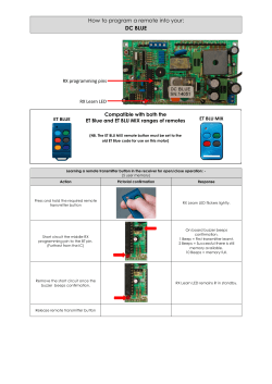


© Copyright 2026