
PDE-1 INSTRUCTION MANUAL
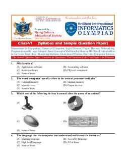
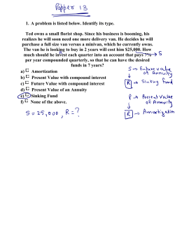
PDE-1 PAGING AND DIALING ENCODER INSTRUCTION MANUAL Model Features Supports 10 pager formats simultaneously 155 entry alias database Two-tone formats include Motorola, GE, Reach Send any arbitrary 2 tones for Plectron Generates POCSAG Supports DTMF and several 5-tone formats Easy to read backlit LCD display Serial printer logging (w/optional cable) MANUAL REVISION: 2013-07-19 COVERS PRODUCT SOFTWARE VERSION(S): 1.2 1.3 1.4 1.41 _____ WITH ENCODER/DECODER VERSION(S): 1.1 _____ _____ _____ _____ MIDIAN ELECTRONICS, INC. To Order: 1-800-MIDIANS 2302 East 22nd Street Telephone: (520) 884-7981 Tucson, Arizona 85713 [email protected] 1 SPECIFICATIONS Voltage/Current Operating Voltage (nominal) ................................. 12 VDC Operating Voltage (min-max) ...........................12-15 VDC Operating Current (standby @12 VDC) ................. 100 mA Operating Current (peak @15 VDC) ...................... 500 mA Inputs Input Level (RX) ..................................... 100-3000 mV p-p Input Impedance (RX) ............................................. > 10k Outputs Output Level (TX, unloaded) .................. 150-2500 mV p-p Output Impedance (TX)........... 27k with jumper JU-4 cut Mechanical Dimensions: ..................................... .2⅞"H x 6½W x 8¾"L Operating Temp ................................................ 0° to 50° C Encode Formats AVCALL, GE, REACH, MOTOROLA QUICK CALL 1 (2+2) AND QUICK CALL 2 (1+1), PULSE 1500/2805, DTMF, CCIR, EEA, EIA, ZVEI, DZVEI, DDZVEI, NATEL, MODAT, and POCSAG. PLECTRON and other 2-tone formats supported with ‘any 2-tone’ format. Quick Call 1 & 2 are trademarks of Motorola. Other Alias Database Size ................................................... .155 MIDIAN ELECTRONICS INCORPORATED PAGE 3 TABLE OF CONTENTS 1 SPECIFICATIONS ........................................................................................................................... 2 2 OVERVIEW ................................................................................................................................ 4 3 INSTALLATION INSTRUCTIONS .............................................................................................. 4 4 5 6 3.1 RADIO INTERFACE................................................................................................................................. 4 3.2 JUMPER SETTINGS................................................................................................................................ 4 3.3 ADJUSTMENTS ...................................................................................................................................... 4 OPERATION .............................................................................................................................. 5 4.1 BASIC OPERATION ................................................................................................................................ 5 4.2 CALLING A UNIT.................................................................................................................................... 6 4.3 USER DATABASE .................................................................................................................................. 6 4.4 SPEED DIAL FEATURE ........................................................................................................................... 7 4.5 SAVED MESSAGES FEATURE ................................................................................................................. 7 4.6 SECURITY FEATURE .............................................................................................................................. 7 MENU SYSTEM.......................................................................................................................... 7 5.1 CALL A UNIT COMMAND ...................................................................................................................... 7 5.2 LOCK OR UNLOCK COMMAND ............................................................................................................. 8 5.3 USERS MENU ...................................................................................................................................... 8 5.4 SAVED MESSAGES MENU ................................................................................................................. 9 5.5 SETUP MENU....................................................................................................................................... 9 APPENDIX ............................................................................................................................... 13 6.1 SYSTEM ERROR MESSAGES ................................................................................................................ 13 6.2 TONE CHARTS .................................................................................................................................... 15 6.3 MENU SYSTEM MAP ............................................................................................................................ 18 PAGE 4 MIDIAN ELECTRONICS INCORPORATED 2 OVERVIEW The PDE-1 is a multi-format paging and dialing encoder. It will support up to 10 different formats simultaneously from the over 35 available. The userfriendly menu system makes it as easy to use as a cell phone. 2-Tone Formats: AVCALL, GE, REACH, and most Motorola 1+1 and 2+2 plans. In addition, the ‘any 2tone’ feature allows for direct entry of any 2 arbitrary frequencies to support PLECTRON and other 2-tone formats without a standardized code plan. Other Tone Formats: DTMF, Pulse tone (1500 or 2805), 5/6-tone EIA, EUROSIGNAL, ZVEI, DZVEI, DDZVEI, EEA, NATEL, and MODAT. Digital Formats: POCSAG 512, 1200, 2400, numeric or alphanumeric. 10 Flexible Pager Profiles: Allows up to 10 different pager types in the same system. User Database: Allows up to 155 names and numbers to be stored for easy access. Call a pager by name or number. Other Features: 10-entry speed dial list. Saved message list allows 10 ‘canned’ alphanumeric messages up to 25 characters long to be saved for instant access. Security feature helps prevent unauthorized personnel from tampering with the PDE configuration. Can operate as a local remote control with optional microphone. Outgoing pages can be logged to a serial printer or PC with optional cable. 3 INSTALLATION INSTRUCTIONS Installation Note: Midian products utilize CMOS integrated circuits, which are susceptible to damage from high static charges. Be sure to follow standard antistatic procedures when handling, including using grounded workstations and soldering irons and wearing grounding bracelets. 3.1 AUDIO INPUT/RX IN (P1-8) [Blue] This connection is only required if you wish to hear radio audio through the PDE speaker. Connect to a point in the radio where squelch controlled receive audio is present at a constant level. AUDIO OUTPUT/TX OUT (P1-4) [Green] For tone formats you can usually connect to the mic-hi input of the radio. The output impedance of the PDE can be adjusted if necessary by replacing leaded resistor R81 with an appropriate value. For digital formats (POCSAG), it may be necessary to connect directly to the modulator inside the radio. PTT OUTPUT (P1-3) [Yellow] This open collector output provides a ground to key-up the radio when transmitting. If connecting to a relay in the radio, make sure the coil is bypassed with a diode to eliminate counter-EMF. COR INPUT (P1-1) [Gray] This connection is required only if you desire to activate the Busy Lockout feature of the PDE. Connect to a point in the radio squelch or CTCSS circuit that changes logic level when carrier (or CTCSS) is detected. A radio whose circuitry provides a logic-low or logic-high can readily turn Q1 on and off. If only a high level is provided, it may be necessary to move R40 from its pull-up to its pull-down position. MONITOR OUTPUT (P1-7) [Orange] This output can be used to control the monitor function of the radio using the <MONITOR> button on the PDE. This is an open collector output which changes state each time the <MONITOR> button is pressed. SQ OUT/LTR IN (P1-2) [Brown] This wire is not used by the PDE. RADIO INTERFACE 3.2 Radio Interface connector P1 is an 8-pin RJ-45 style connector in the center of the back panel. +V IN (P1-5) [Red] The PDE can be powered either by an optional wall transformer or by the radio power supply. Connect this wire to the radio power source provided it is between 12 and 15 VDC. If using a wall transformer, make sure the voltage is between 12 and 15 VDC and the current rating is at least 500mA. Also, be certain that positive is connected to the center pin (inside sleeve). GROUND (P1-6) [Black] Connect to radio ground. JUMPER SETTINGS There are two user configurable jumpers, JU1 and JU4. Both are installed at the factory. JU1 allows signaling audio to be heard in the local speaker. If this is not desired, cut JU1. JU4 controls the output impedance of transmit audio. See OUTPUT LEVEL below to determine if JU4 will need to be cut. 3.3 ADJUSTMENTS Once the unit has been connected to the radio, several adjustments must be made to achieve proper operation. It will be necessary to open the unit. Use the pictorial to identify the location of the following trim pots: R32 near connector P3, R51 near IC U6, and R105 near the volume control. MIDIAN ELECTRONICS INCORPORATED PAGE 5 OUTPUT LEVEL Use a service monitor to measure the modulation level generated by the unit. Cause the unit to generate tones by first pressing <SEND> at the CALL A UNIT prompt and then typing in 1000010000 and pressing <SEND>. Adjust R51 so that the modulation level is at 2/3 of the maximum system modulation (typically 3.3 kHz). If the output level cannot be adjusted low enough, it will be necessary to cut JU4. This changes the output from low impedance to high impedance. MICROPHONE GAIN If an optional microphone is installed, the microphone audio level must be adjusted. Cause the unit to go into transmit mode by holding down the <SEND> key. Speak loudly into the microphone at a normal distance. Adjust R105 such that maximum system modulation is achieved at peak voice. SPEAKER PRE-AMP SCROLL INDICATORS – An arrow appearing on either side of the display indicates more choices are available by pressing the corresponding <SCROLL> button. <SEND> Button – Selects the item shown on the display. Press <SEND> when CALL A UNIT is displayed and you will enter Call Mode. In Call Mode, you will be prompted for CAP code (or a User Name). As shipped from the factory, you can place a Motorola general 1+1 page right now by typing a 3-digit CAP code, followed by <SEND>. If you press <SEND> without typing in a CAP code, it will act like the PTT button of the radio. Though the PDE has a volume control knob, it also has an input audio pre-amplifier. While listening to audio on the channel, adjust R32 so that the minimum and maximum volume control settings are at desired levels. <#> POUND Button – This button is used any time you wish to escape the current selection or abort data entry. Press this key to escape the Call Mode and return the PDE to the Main Menu. Repeatedly pressing the <#> button will always return the PDE to the Main Menu. PRINTER OPTION 4.1.2 With an optional cable, the PDE can log paging activity to a serial printer or even a PC equipped with a COM port. The PDE printer port configuration is fixed at 9600 baud, 8 data bits, 1 stop bit, and no parity. To use the printer, you will have to turn the printer option on in the CONSOLE SETUP. Next, plug the modular plug of the cable into P4 (closest to the volume control). You may need a 9 to 25-pin adapter to connect to your printer. If you choose to log to a PC, you will need a null modem. <MONITOR> - This button always controls the monitor function of the radio (if monitor output connected). Press <MONITOR> to toggle the state of the monitor output to the radio. 4 OPERATION 4.1 BASIC OPERATION 4.1.1 Navigating the PDE The PDE starts off at the Main Menu as illustrated below. Other Controls and Indicators POWER / ALARM LED – Glows red when power is turned on. TRANSMIT / BUSY LED – This LED is off when there is no activity. It glows red during transmit. It blinks green any time the radio channel is busy (provided COR input is active and connected). NUMBER Keys – The number keys are used for both numeric and alphanumeric data entry. They may also be used as Speed Dial buttons if the feature is enabled. <*> STAR Button – Pressing the <*> will toggle the data entry mode between numeric and alphanumeric where this is appropriate (such as when entering POCSAG messages). It can also be used to enter special DTMF characters *,#,A,B, and C (‘D’ is not supported). 4.1.3 Data Entry The PDE supports two modes of data entry: numeric and alphanumeric. When numeric entry is called for such as when entering a CAP code, simply press the appropriate number keys. Alphanumeric entry is called PAGE 6 MIDIAN ELECTRONICS INCORPORATED for when entering User Names or messages for POCSAG alpha pagers. Entering alphabetic characters using the numeric keypad is easy. All of the letters of the alphabet appear above the numbers on the keypad. For example, the letters ‘A’ ‘B’ and ‘C’ appear on the <2> key. Alphabetic characters are entered by pressing 2 digits. The first digit is the key with the desired letter appearing on it. The 2nd digit is the position of the letter on that key. For example, the code for the letter ‘C’ is 23 since it is the 3rd letter on the <2> key. The letter ‘T’ is the 1st letter on the <8> key, so its code is 81. To enter numeric characters in alphanumeric mode, press the <0> key followed by the desired digit. Punctuation characters such as comma <,> and <-> do not appear on the keypad. Special codes have been assigned to allow entry of those characters. Please refer to the following chart. During data entry, the left <SCROLL> button acts as backspace, and the <#> button aborts data entry. In some cases, you can use the <*> button to toggle between numeric and alphanumeric entry (more on this later on). 4.2 CALLING A UNIT 4.2.1 Automatic Pager Profile Selection At this time, you may wish to connect the audio output (green wire) of the PDE to an amplified speaker so you can hear the paging tones go out. Select CALL A UNIT from the Main Menu. Type in 3 digits and press <SEND>. You should hear a 1 second tone followed by a 3 second tone. You have just sent a Motorola General Plan 1+1 page. Now try typing in a 4-digit number. You should hear DTMF tones. You may ask, how does the PDE know which paging format to use? Later on, when there are entries in the User Database, the PDE will determine the format based on the information in the database. Right out of the box, the PDE database is blank so another method is used. The PDE picks the Pager Profile automatically based on the number of digits entered. Enter 3 digits and profile 3 is chosen. Enter 10 digits and profile 10 is used. This was done so that the PDE would work right out of the box. Each of the 10 pager profiles were initialized at the factory with examples. Try entering 7 digits and you can do a POCSAG page. 4.2.2 Changing Pager Profiles A=21 I=43 Q=72 Y=93 7=07 - =15 B=22 J=51 R=73 Z=94 8=08 + =16 C=23 K=52 S=74 1=01 9=09 ] =17 D=31 L=53 T=81 2=02 0=00 * =18 Say you have pagers that work with Motorola code plan ‘L’. You can change profile 3 to match this format. Navigate to SETUP->PAGER SETUP->Profile 3 and press <SEND>. You will first be prompted for a Profile Name. You can call it whatever you want, let’s say MOT L: E=32 M=61 U=82 3=03 . =11 / =19 61 63 81 10 53 <SEND> F=33 N=62 V=83 4=04 , =12 G=41 O=63 W=91 5=05 ?=13 H=42 P=71 X=92 6=06 [=14 =10 Space The code 10 is used to insert a space between characters. 4.1.4 Entering Special DTMF Digits The PDE supports the following special DTMF 'digits' in numeric entry mode: *, #, A, B, and C (D is not supported). These are entered using 2-key sequences as follows: *=** #=*# A=*1 B=*2 C=*3 These special digits can only be entered when adding a User ID to the database. They cannot be dialed directly from the call mode (unless the database is empty). Also, these special sequences should not be used unless you are using DTMF as the encode format. Next you will be prompted for pager type. It should already say ‘2-Tone’, just press <SEND>. Next you will be prompted for the pager Format. Scroll right until you find ‘MOTOROLA L’ and press <SEND>. Next you will be prompted for the 1st and 2nd tone times. They have already been set for 1000 and 3000 milliseconds respectively, which is correct for Motorola. Press <SEND> for each one. You will hear a confirmation signal. Changes do not take effect until the confirmation beeps are heard. Now all 3-digit pages will be in the Motorola L format. This was just one example of a pager profile. The information prompted for will be depend on pager type. For example, a POCSAG pager profile includes a baud rate setting. Please refer to section 5.5.4, PAGER SETUP. 4.3 USER DATABASE The user database makes day-to-day operation of the PDE much easier. You can use easy-to-remember names instead of just numbers. It is advised that the pager profiles be setup before setting up the user database. MIDIAN ELECTRONICS INCORPORATED 4.3.1 User Database Features The primary purpose of the user database is to associate a name (or alias) with a pager profile and CAP code. This way, when you go to place a page, the name of the person can be selected from the database. The PDE can store up to 155 aliases in its database. The PDE retains the database memory even when switched off. 4.3.2 Setting Up the User Database Begin by compiling a list of names along with the pager profiles and CAP codes. Give some thought on how you are going to abbreviate the names since only 14 characters per name are available. To begin entering data, select Add User from the USERS menu. See the description of these items in the USERS menu section 5.3 for more information. 4.3.3 Calling a Unit in the Database To place a call to a unit in the database, first select CALL A UNIT from the Main Menu. Press the right <SCROLL> button to display the first user in the database. Either the CAP code will be displayed, or the User Name (alias) will be displayed. This is determined by the Call Entry Mode setting. Once there are entries in the database, you should navigate to: SETUP->CONSOLE SETUP->Call Entry Mode and change this setting to ALPHA. By doing this, you will automatically be prompted for a User Name instead of a CAP code. You can always use the <*> button to toggle the entry mode between numeric (CAP code) and alphanumeric (User Name). The <*> button can also be used to see which CAP code is assigned to the User Name shown in the display. In either case, after pressing the right <SCROLL> button, the left and right scroll indicators will appear on the bottom line. This indicates that the PDE is in the Select Mode. Use the <SCROLL> keys to locate the desired user within the database. When the name is located, press the <SEND> key to place the call. The <#> key may be used at any time prior to pressing <SEND> to cancel the call. To locate a user in the database more quickly, you can enter one or more of the first few letters of the User Name code prior to pressing the right <SCROLL> button. The PDE will search the database for users matching the first few letters. You can also do the same thing in numeric entry mode, but with numbers. 4.4 SPEED DIAL FEATURE When the speed dial feature is enabled, you can simply press and hold any of the digits 0-9 for 1.5 seconds to place a call (when in Call Mode only). First, you must enter each user assigned to a speed dial button into the database. Then, navigate to PAGE 7 SETUP->SPEED DIAL SET->Speed Dial And turn the feature on. Next, scroll right and select the speed dial button you wish to assign to a user. Locate the user in the database in the same manner as if placing a call. 4.5 SAVED MESSAGES FEATURE The PDE can stored up to 10 ‘pre-canned’ messages of up to 25 characters each for use with POCSAG paging. See section 5.4 on SAVED MESSAGES for information on entering the messages. See section 5.1.1 on POCSAG Message Entry for how to recall saved messages when doing a POCSAG page. 4.6 SECURITY FEATURE The menu system incorporates a lock feature to prevent unauthorized personnel from changing the PDE configuration. The lock feature also serves to simplify day-to-day operation of the unit. When the LOCK command is selected, all of the menus are disabled. The only items available will be CALL A UNIT and UNLOCK. Selecting UNLOCK makes all of the menu items available again. When locked, the unit is password protected so only authorized personnel may unlock the menus. As shipped from the factory, the security feature is disabled and the LOCK/UNLOCK options do not appear. To enable the feature and select a password, see the SECURITY SETUP menu item. Remember your password! Once security is enabled and the menus are locked, the only way to unlock will be to use the password. If you do forget the password, contact Midian for the reset procedure. 5 MENU SYSTEM The following sections describe the various functions of the menu system. Factory default settings are underlined. 5.1 CALL A UNIT COMMAND Places the unit into Call Mode. All pages are done from Call Mode. Selecting a unit to call may be done in several ways. Speed Dial mode – If speed dial is enabled, simply press and hold the number key associated with the unit you wish to call. If the speed dial key continues to be held after the page is complete, it will serve to keep PTT asserted for voice-over paging. For the following four modes, the <SEND> key is pressed to send the page. If doing voice-over paging, keep the <SEND> key pressed to hold up PTT. Direct Numeric Entry mode – Simply key in the CAP PAGE 8 MIDIAN ELECTRONICS INCORPORATED Code of the unit you wish to call. Direct Alphanumeric Entry mode – Key in the User Name as it appears in the user database. Numeric Select mode – Press the right <SCROLL> button to enter select mode. Now you can use both left and right <SCROLL> buttons to select a CAP code from the database. Also, you may enter a partial CAP code prior to pressing right <SCROLL> to find the 1st entry in the database matching the partial code. Alphanumeric Select mode – Press the right <SCROLL> button to enter select mode. Now you can use both left and right <SCROLL> buttons to select a CAP code from the database. Also, you may enter a partial name prior to pressing right <SCROLL> to find the 1st entry in the database matching the partial name. Remember, you can use the <*> to toggle between numeric and alphabetic entry modes. Press <SEND> to make the call. When sending to a POCSAG pager, you will then be prompted for a numeric or alphanumeric message. Entering a message may be done in several ways. 5.1.1 POCSAG Message Entry Numeric Entry mode – Simply key in the numeric message up to 14 digits. Alphanumeric Entry mode – Key in an alphanumeric message up to 25 characters. Select mode – Press the right <SCROLL> button to enter select mode. Now you can use both the left and right <SCROLL> buttons to select a message from the list of 10 ‘pre-canned’ messages in the Saved Messages list. Press <SEND> after message entry to place the page. Note: Numeric POCSAG pagers can decode the following special non-numeric characters: space ? U - [ ]. Alphanumeric entry mode is required to enter these special ‘numeric’ characters. Note that the U character is typically understood to mean ‘urgency’. Press <#> to escape the Call mode and return to the Main Menu. 5.2 LOCK OR UNLOCK COMMAND Note The LOCK and UNLOCK menu options do not appear unless enabled in SECURITY SETUP. Selecting LOCK will disable access to the parts of the menu system described in the following sections. Select UNLOCK to enable the entire menu system. You must enter a 4-digit password to unlock the menu system. See SECURITY SETUP for more information. 5.3 5.3.1 USERS MENU Add User menu Allows the system administrator to add a new user to the database. When ADD USER is selected, you will be prompted to fill in the information for that user such as User Name and CAP Code. See EDIT USER for more information. 5.3.2 Delete User menu Allows you to delete a user record from the database. When DELETE USER is selected, you will be able to select the user you wish to delete in the same manner as if placing a call to a unit. Use the scroll buttons to find the user you wish to delete. Press <SEND> to delete the selected user. You will have to press <SEND> a second time to confirm. Press <#> to cancel if you change your mind. 5.3.3 EDIT USER menu Allows you to change information about a user. Select the user you wish to edit in the same manner is if placing a call to that user. Use the scroll buttons to find the user you wish to edit. Press <SEND> to edit the information for the selected user. You will be prompted to fill out each field in turn. After entering the data for a field, press <SEND> to go on to the next field. To leave a field unchanged, simply press <SEND> without entering data. 5.3.3.1 User Name field This alphanumeric field contains the name of the user associated with a unit. A maximum of 14 characters may be used. A name already in the database will not be accepted. See the Data Entry section for more information. Range: 0-14 characters Default: blank 5.3.3.2 Pager Profile setting Select from among the 10 pager profiles by name using the <SCROLL> buttons. Range: 0-14 characters Default: N/A 5.3.3.3 CAP Code field or Frequency fields If the pager type is 2-tone, 5-tone, DTMF, or POCSAG, You will be prompted for a numeric CAP code to be associated with the unit. If using AVCALL, see the section 6.2.1 for entry instructions. If using Motorola Quick Call 1 (2+2), see section 6.2.2 for entry instructions. Range: 1-10 digits depending on pager format Default: blank If the pager type is ‘any 2-tone’ you will be prompted to enter two 5-digit frequencies. The 1st digit is the 1000’s place and the last the 1/10’s place. For example 615.8 Hz is entered as 06158, 1985.0 Hz is entered as 19850. Technically, you can enter anything from 0000.0 to 9999.9 Hz, however the practical maximum is about 3000.0 Hz. Range: 5 digits MIDIAN ELECTRONICS INCORPORATED Default: 5.4 blank SAVED MESSAGES MENU Allows you to edit each of the 10 saved alphanumeric messages used in POCSAG paging, These messages, each up to 25 characters in length, are saved even when power is turned off. Though these entries are alphanumeric, they can also be used with numeric only pagers provided the message is limited to the characters 0123456789?U-][ and space. 5.4.1 Message 1 Range: 0-25 characters Default: blank 5.4.2 Message 2 Range: 0-25 characters Default: blank 5.4.3 Message 3 Range: 0-25 characters Default: blank 5.4.4 Message 4 Range: 0-25 characters Default: blank 5.4.5 Message 5 Range: 0-25 characters Default: blank 5.4.6 Message 6 Range: 0-25 characters Default: blank 5.4.7 Message 7 Range: 0-25 characters Default: blank 5.4.8 Message 8 Range: 0-25 characters Default: blank 5.4.9 Message 9 Range: 0-25 characters Default: blank 5.4.10 Message 10 Range: 0-25 characters Default: blank 5.5 5.5.1 SETUP MENU SPEED DIAL SETUP menu Allows you to configure the speed dial feature. The PAGE 9 speed dial entries 0-9 correspond to the number keys 0-9. To associate a unit to a speed dial number, it must be in the user database. For each speed dial, simply locate the user in the database much in the same way as placing a call to a unit. 5.5.1.1 Speed Dial feature As shipped, speed dial is disabled. Change this setting to ON to begin using the speed dial feature. OFF Disable speed dial feature. ON Enable speed dial feature. 5.5.1.2 Speed Dial 0 setting Range: 0-14 characters Default: blank 5.5.1.3 Speed Dial 1 setting Range: 0-14 characters Default: blank 5.5.1.4 Speed Dial 2 setting Range: 0-14 characters Default: blank 5.5.1.5 Speed Dial 3 setting Range: 0-14 characters Default: blank 5.5.1.6 Speed Dial 4 setting Range: 0-14 characters Default: blank 5.5.1.7 Speed Dial 5 setting Range: 0-14 characters Default: blank 5.5.1.8 Speed Dial 6 setting Range: 0-14 characters Default: blank 5.5.1.9 Speed Dial 7 setting Range: 0-14 characters Default: blank 5.5.1.10 Speed Dial 8 setting Range: 0-14 characters Default: blank 5.5.1.11 Speed Dial 9 setting Range: 0-14 characters Default: blank 5.5.2 TIME SETUP menu Note: It is necessary to set the time only if using optional printer. In order for the correct time to be PAGE 10 MIDIAN ELECTRONICS INCORPORATED displayed on the print logs, the time clock must be set. The unit must remain switched-on at all times in order to keep track of the time. The clock must be set each time the unit is powered up. 5.5.2.1 Hour setting Set the hour of the day in 24-hour format. Enter two digits. 5.5.3.5 Contrast setting Allows the display contrast to be adjusted for best viewing. LOW Low contrast setting. HIGH High contrast setting. 5.5.3.6 Mic. Option setting 5.5.2.2 Minute setting Selects which type of optional microphone accessory is attached to the PDE. This is necessary so that the PDE knows how to treat the external inputs (for example off-hook or monitor). Set the minutes past the hour. Enter two digits. NONE Range: 00-59 GOOSENECK Gooseneck style microphone. Default: 00 PADDLE Paddle style desktop microphone. HANDSET External handset. Range: 00-23 Default: 00 5.5.3 CONSOLE SETUP menu No microphone. 5.5.3.7 Printer Option Determines if numeric entry or alphanumeric data entry is the default mode when placing a call. The mode of entry can be toggled by pressing the <*> key during data entry. The PDE, if ordered with the printer cable option, can log the ANI traffic to a serial printer. The printer must have a print buffer and a standard RS-232 port. It must be configured for 9600 baud, 8 data bits, 1 stop bit and no parity. In order to send data to the printer, this option must be on. NUMERIC Start in numeric only mode. OFF Do not send data to printer. ALPHA Start entry in alphanumeric mode. ON Send data to printer. 5.5.3.1 Call Entry Mode setting 5.5.3.2 Fast Scrolling setting Fast Scrolling allows for faster navigation through the menu system. The PDE can also animate the scrolling of the screen from side-to-side. This provides positive feedback in response to scrolling through menus and the ANI log. If this effect is desired, Fast Scrolling can be disabled. 5.5.4 PAGER SETUP menu Allows you define up to 10 different pager types. There are 10 pager Profiles consisting of the fields described below. Each profile has a factory default setting intended as examples to follow. OFF Animate scrolling from side to side. 5.5.4.1 Profile Name field ON Scroll at fast speed. Turning this option on causes a beep to be heard for each key press. If this option is off, only error and confirmation tones will be heard. This can be any alphanumeric string up to 14 characters. The name should be chosen based on the pager description such as ‘MOT PLAN L’ or ‘POC ALPHA 12’. When a user is added to the database, you will be able to scroll through the 10 profile names and select the appropriate one. OFF Keypad beeps off. 5.5.4.2 Pager Type field ON Keypad beeps on. Select the basic pager type. You will then be prompted for more information based on the pager type. The following pager types are available: 5.5.3.3 Keypad Beep option 5.5.3.4 Internal Speaker setting If audio input of the PDE is connected to the radio, it’s audio may be heard from the PDE speaker. If this is not desired, turn this setting off. Note that if this setting and the Keypad Beep option are both turned off, error and confirmation beeps can still be heard. If it is desired that absolutely no sound be heard from the console speaker, simply disconnect it from the main circuit board. OFF Internal speaker disabled. ON Internal speaker enabled. 2-Tone 5/6-Tone Pulse Tone Any 2 tones DTMF POCSAG MIDIAN ELECTRONICS INCORPORATED PAGE 11 5.5.4.3 2-Tone type EIA 5.5.4.3.1 Format field EUROSIGNAL Select the format matching the pager from among the following: ZVEI AVCALL/QC1 2+2 GE DZVEI DDZVEI CCIR REACH EEA MOT GENERAL MOTOROLA A NATEL MODAT MOTOROLA B 5.5.4.4.2 1st Tone Time field MOTOROLA C Enter the duration of the 1st tone in milliseconds. For EIA pagers, this is typically 33 milliseconds. All 4 digits must be entered. MOTOROLA D MOTOROLA E Range: MOTOROLA F 0000 to 9999 milliseconds 5.5.4.4.3 Nth Tone Time field MOTOROLA G MOTOROLA J Enter the duration of for each of the tones that follow the 1st tone in milliseconds. For EIA pagers, this is typically 33 milliseconds. All 4 digits must be entered. MOTOROLA K Range: MOTOROLA H MOTOROLA M 0000 to 9999 milliseconds 5.5.4.5 Pulse Tone type MOTOROLA N 5.5.4.5.1 Format field MOTOROLA P Choose the tone frequency. MOTOROLA Q 2805 MOTOROLA R 1500 MOTOROLA S 5.5.4.5.2 Make Time field MOTOROLA T Enter the make time (on-time) of each pulse. The ‘break’ time (off-time) will be 1.5 times the make time. For example, if the make time is 40 ms, the break time is 60 ms. All 4 digits must be entered. MOTOROLA U MOTOROLA V MOTOROLA W Range: 0000 to 9999 milliseconds st 5.5.4.3.2 1 Tone Time field Enter the duration of the 1st tone in milliseconds. For Motorola pagers, this is typically 3 seconds (3000 milliseconds). All 4 digits must be entered. Range: 0000 to 9999 milliseconds 5.5.4.3.3 2nd Tone Time field Enter the duration of the 2nd tone in milliseconds. For Motorola pagers, this is typically 1 second (1000 milliseconds). All 4 digits must be entered. Range: 0000 to 9999 milliseconds 5.5.4.4 5/6-Tone type 5.5.4.4.1 Format field Select the format matching the pager from among the following: 5.5.4.5.3 Tail Time field Enter the duration that tone should remain on after dialing. All 4 digits must be entered. Range: 0000 to 9999 milliseconds 5.5.4.6 Any 2 Tones type Note that this format is provided to support PLECTRON and other formats which do not conform to a standardized code plan. 5.5.4.6.1 1st Tone Time field Enter the duration of the 1st tone in milliseconds. In the PLECTRON fast format, this is 750 ms. All 4 digits must be entered. Range: 0000 to 9999 milliseconds PAGE 12 MIDIAN ELECTRONICS INCORPORATED 5.5.4.6.2 2nd Tone Time field nd Enter the duration of the 2 tone in milliseconds. In the PLECTRON fast format, this is 250 ms. All 4 digits must be entered. Range: 0000 to 9999 milliseconds follows: Profile Name: Pager Type: Format: Make Time: Tail Time: PULSE 2805 Pulse Tone 2805 0040 1000 5.5.4.7 DTMF type 5.5.4.9.2 Profile 2 5.5.4.7.1 On Time field The factory default settings for this profile are as follows: Enter the tone on-time. All 4 digits must be entered. Range: 0000 to 9999 milliseconds 5.5.4.7.2 Gap Time field Enter the gap time between tones. All 4 digits must be entered. Range: 0000 to 9999 milliseconds 5.5.4.8 POCSAG type Profile Name: REACH 2-TONE Pager Type: 2-Tone Format: REACH 1st Tone Time: 2000 2nd Tone Time: 0700 5.5.4.9.3 Profile 3 The factory default settings for this profile are as follows: NUMERIC Numeric only pager. Profile Name: MOT GENERAL Pager Type: 2-Tone Format: MOT GENERAL 1st Tone Time: 1000 2nd Tone Time: 3000 ALPHA Alphanumeric pager. 5.5.4.9.4 Profile 4 5.5.4.8.1 Pager Display field Set the display type of the pager. 5.5.4.8.2 Baud Rate field Set the baud rate of the pager. The factory default settings for this profile are as follows: Profile Name: Pager Type: On Time: Off Time: 512 1200 2400 5.5.4.8.3 Invert field If Invert is on, the POCSAG data bits are inverted. Whether or not this needs to be done will depend on the radio and installation point. Determine this setting by experiment. OFF Do not invert bits. ON Invert POCSAG data bits. DTMF DTMF 0050 0050 5.5.4.9.5 Profile 5 The factory default settings for this profile are as follows: Profile Name: EIA 5-TONE Pager Type: 5/6-Tone Format: EIA 1st Tone Time: 0033 Nth Tone Time: 0033 5.5.4.8.4 Function Bits field 5.5.4.9.6 Profile 6 The way a pager handles the function bits depends on the specific pager. In some instances, they control which sound the pager makes when it goes off. The factory default settings for this profile are as follows: 10 Profile Name: EUROSIGNAL Pager Type: 5/6-Tone Format: EUROSIGNAL 1st Tone Time: 0100 Nth Tone Time: 0100 11 5.5.4.9.7 5.5.4.9 Pager Profiles and Defaults The factory default settings for this profile are as follows: 00 01 The following shows the factory default pager profile settings that allow the PDE to function ‘out of the box’. Please refer to section 4.2.1 for more information. 5.5.4.9.1 Profile 1 The factory default settings for this profile are as Profile 7 Profile Name: POCSAG-NUMERIC Pager Type: POCSAG Pager Display: NUMERIC Baud Rate: 1200 Invert: OFF MIDIAN ELECTRONICS INCORPORATED Function Bits: 00 5.5.4.9.8 Profile 8 The factory default settings for this profile are as follows: Profile Name: QUICK CALL 1 Pager Type: 2-Tone Format: AVCALL/QC1 2+2 1st Tone Time: 1000 2nd Tone Time: 1000 5.5.4.9.9 Profile 9 PAGE 13 New calls cannot be placed until the pending call is completed or canceled. When this option is OFF, the unit will transmit regardless of the state of the COR input. OFF Transmit regardless of COR input. ON Do not transmit when channel busy. 5.5.6 SECURITY SETUP menu 5.5.6.1 Security setting The factory default settings for this profile are as follows: Allows the security option to be turned on and off. If turned off, the LOCK/UNLOCK menus will not appear. Profile Name: GE 2-TONE Pager Type: 2-Tone Format: GE 1st Tone Time: 1000 2nd Tone Time: 1500 OFF Disable security feature. ON Enable security feature. 5.5.4.9.10 Profile 10 The factory default settings for this profile are as follows: Profile Name: PLECTRON-FAST Pager Type: Any 2-Tones 1st Tone Time: 0750 2nd Tone Time: 0250 5.5.6.2 Password setting Sets the password required to UNLOCK the menu system when the Security is turned on. Must be 4 numeric digits. Range: 4 digits Default: 0000 5.5.7 UTILITIES menu 5.5.7.1 Reset Defaults 5.5.5 RADIO SETUP menu 5.5.5.1 Keyup Delay setting This sets the Key-Up Delay, also known as Front Porch Time. This is the amount of time the PDE will wait after asserting PTT before sending tones over the air. This time allows for delays introduced by repeaters and decoding of squelch control signals such as CTCSS. Range: 01 to 99 * 100 milliseconds Default: 04 * 100 milliseconds This will reset all the parameters listed above to the factory default settings. The contents of the user database will not be affected. 5.5.7.2 Clear Database This will completely clear the user database. The contents of the other parameters listed above will not be affected. 5.5.7.3 Factory Debug This is used by the factory for product testing. Do not select this function unless directed to do so by Midian Technical Support. 5.5.5.2 COR Polarity setting Note: If not using the Busy Lockout feature, you may leave the COR input unconnected. The COR input is used in conjunction with the Busy Lockout feature. Change this setting to match the state of the COR (carrier detect) input when the radio channel is busy. LOW Channel is busy when COR is 0V. HIGH Channel is busy when COR is 5V. 5.5.5.3 Busy Lockout feature This feature prevents the PDE from transmitting on a busy channel. If this feature is ON, the unit will not transmit when the COR input is in the active state. When making a call and the channel is busy, the PDE will wait until the channel is clear and then transmit. 6 APPENDIX 6.1 SYSTEM ERROR MESSAGES CHANNEL BUSY Reason: An attempt was made to transmit or make a call on a busy channel with busy lockout enabled. Solution: Wait until the channel is clear before transmitting. DATABASE EMPTY Reason: An attempt was made to edit or delete a user PAGE 14 when the database was empty. Solution: These functions do not apply when the database is empty. DATABASE FULL Reason: An attempt was made to add a user to the database and there is no more room. The maximum number of user aliases of 155 cannot be exceeded. Solution: Remove any old user names that are no longer in service. If this is not possible, contact Midian for possible alternative products. MIDIAN ELECTRONICS INCORPORATED This can happen in the if the total time of the key-up delay and encoding exceeds 20 seconds. This is not likely to happen unless non-standard encode timings and encode lengths are used. It is also possible that there could be a hardware failure. Solution: If total time of the key-up delay and signaling tones exceeds 20 seconds, simply press <SEND> to clear the message from the display. The page will still be sent. In the event of a hardware failure, contact Midian technical support to determine if that is the cause. INVALID CAP CODE DATABASE ERROR Reason: The number of digits in the CAP code are incorrect for the pager format being used. Reason: One or more entries in the user database has been corrupted. This can happen if power is lost at the exact time the database is being updated. Any corrupted records will be blanked-out and must be reentered. Solution: Enter the correct number of digits. Most builtin 2-tone formats require exactly 3 digits. POCSAG requires 7 digits, and ‘any 2-tone’ requires 10 digits. The other formats can accept 1-10 digits. Solution: Cycle power to the unit. This should clear the error. If the error message continues to come up, contact Midian technical support. NOT FOUND Reason: There is no entry in the user database that matches the data entered. Solution: Choose a unique user name for each user. If it is necessary to edit the user record, use the edit menu. Solution: When selecting a user to call, the name or the CAP code can be entered in whole or in part. When entering a partial name or CAP code, press the right <SCROLL> button to search the database for the first partial match. Press <SEND> only if the whole CAP code or name has been entered. There may be no entry in the database that matches in whole or in part. In that case, the user must be added to the database. EE CHKSUM ERR NOT NUMERIC MESSAGE Reason: The configuration settings stored in EEPROM have been corrupted. This can happen if power is lost at the exact time a parameter is being updated. All configuration settings will be set back to defaults. The user database should not be affected. Reason: You are trying to send a message containing non-numeric characters (other than those below) to a POCSAG pager designated as being numeric only. DUPLICATE NAME Reason: An attempt was made to add a user name to the database which is already in the database. Each user name in the database must be unique. Solution: Cycle power to the unit. This should clear the error. If the error message continues to come up, contact Midian technical support. Solution: Restrict your entry to POCSAG ‘numeric’ characters only. These are 0123456789?U-][ and space. PROFILE IN USE EE WRITE FAIL Reason: The EEPROM chip or connections to it have failed. Solution: Contact Midian for instructions on getting the unit repaired. ENCODER TIMEOUT Reason: The PDE expects a page to be completed within 20 seconds and this time has been exceeded. Reason: You have selected a pager profile to edit that is associated with a user in the database. This message is provided as a warning so that you do not change a user’s profile unintentionally. Solution: You may either press <#> to cancel your selection, or press <SEND> to proceed to view or edit the selected profile. Changing an already assigned profile may cause problems if the profile changes, say, from POCSAG to 2-Tone because 2-Tone users cannot have 7-digit CAP codes! Please keep this in mind if you proceed to do this. MIDIAN ELECTRONICS INCORPORATED SPEED DIAL EMPTY Reason: You have pressed a speed dial number, but there is no user associated with it. The user may have been deleted, or no association was ever made. Solution: Go to speed dial setup and associate a user in the database to the speed dial number. 6.2 TONE CHARTS Below are tone charts for some selected formats provided for your convenience. For an extensive collection of full-size tone charts, please view our online tone charts at: http://www.midians.com/pdf/tone_signaling.pdf 6.2.1 AVCALL CAP code entry AVCALL is not like the other tone formats in that the CAP code consists of alphabetic characters instead of numbers. To overcome this, AVCALL CAP codes must be entered as 2 digits per letter. A total of 8 digits must be entered. Refer to the following conversion chart. PAGE 15 PDE-1 CODE 00 01 02 03 04 05 06 07 08 09 10 11 12 13 14 15 6.2.2 AVCALL 2+2 AVCALL TONE CODE FREQ A 0312.6 B 0346.7 C 0384.6 D 0426.6 E 0473.2 F 0524.8 G 0582.1 H 0645.7 J 0716.1 K 0794.3 L 0881.0 M 0977.2 P 1083.9 Q 1202.3 R 1333.5 S 1479.1 QUICK CALL 1 CAP code entry Quick Call 1 (2+2) is not like the other tone formats in that the CAP code consists of alphabetic characters instead of numbers. To overcome this, Quick Call 1 CAP codes must be entered as 2 digits per code. A total of 8 digits must be entered. Refer to the following conversion chart PAGE 16 MOTOROLA QUICK CALL 1 TWO PLUS TWO (2+2) OR CODE TYPE “Y” PDE-1 QC1 TONE CODE CODE FREQ SERIES A 16 DA 0398.1 17 EA 0441.6 18 FA 0489.8 19 GA 0543.3 20 HA 0602.6 21 JA 0668.3 22 KA 0741.3 23 LA 0822.2 24 MA 0912.0 25 CA 0358.9 26 NA 1011.6 27 PA 1122.1 B SERIES 28 DB 0412.1 29 EB 0457.1 30 FB 0507.0 31 GB 0562.3 32 HB 0623.7 33 JB 0691.8 34 KB 0767.4 35 LB 0851.1 36 MB 0944.1 37 CB 0371.5 38 NB 1047.1 39 PB 1161.4 Z SERIES 40 DZ 0384.6 41 EZ 0426.6 42 FZ 0473.2 43 GZ 0524.8 44 HZ 0582.1 45 JZ 0645.7 46 KZ 0716.7 47 LZ 0794.3 48 MZ 0881.0 49 CZ 0346.7 50 NZ 0977.2 51 PZ 1084.0 6.2.3 PLECTRON Chart The PLECTRON format does not use CAP codes. Instead, the frequencies of the tones must be entered directly. Use the ‘Any 2-Tones’ format for PLECTRON. MIDIAN ELECTRONICS INCORPORATED 6.2.4 Motorola 2-tone Charts The following Motorola 2-tone information is provided for your convenience. 6.2.5 GE 2-tone Charts The following GE 2-tone information is provided for your convenience. MIDIAN ELECTRONICS INCORPORATED PAGE 17 6.2.7 5/6-tone Chart The following 5/6-tone information is provided for your convenience. 6.2.6 REACH 2-tone Charts The following REACH 2-tone information is provided for your convenience. 6.2.8 Pager Timing Charts The following timing information is provided for your convenience. PAGE 18 6.3 MENU SYSTEM MAP MIDIAN ELECTRONICS INCORPORATED 3 4 3 COU10:1 U10:1 PIU1002 2 16 2A 5 3 4 PIU1004 6 PIU705 COMPin PIU803 VCOout * PIU8012 PIR2801 1 PIR2601 PIR2602 PIR2501 240K 14 9 PITP401 .022u PIC2801 * 100K 47K D P1:1 PIP101 COP1:1 COR PIQ10C 2.7K PIR3901 PIR3902 PIQ10B PIR40A01 PIQ10E COR40A R40A * Q1 COQ1 B25 14 PIU9014 RX IN 6 PIJU602 PIU906 PIJU702 16 PIU9016 19 PIU9019 COC29 C29 PIC2901 .1u PIC2902 +5V PIC7 01 + PIR4101 PIR40B01 R39 COR39 4800 NOTE C77[1uF] USED ONLY FOR SPECIFIC PROD DATES OF U9 5 PIU1205 MISO 34 PIU1034 6 PIU1206 PIR9301 VDD SK N/C 8 PIU1208 SI N/C 1 PIU1201 VSS 7 PIU1207 SO 6 8 PIC6201 PIC5802 C58 COC58 COC62PIC5801 .01u PIC6202 C62 .1u D7 40 PIU1040 NC3 WP VSS COU13 U13 25C320 47K 39 PIU1039 3 PIU1303 4 PIU1304 PIR9302 COU2 U2 68705C9 PIR10602 19 CS SCK 6 PIU1306 36 PIU2036 SCK SI 5 PIU1305 35 PIU2035 MOSI SO 2 PIU1302 34 PIU2034 MISO PIU2019 PIR10202 32 PIU2032 32 33 PIU2033 PIU1033 RDI PIU1032 C2 PIU1029 CKD CD PIU9013 27 PIU1027 13 30 PIU1030 28 C4 PIU2027 26 27 24 PIU2024 25 C6 PIU2025 C2 PIU2029 C1 PIU2030 29 30 NC1 B4 PIU2017 17 15 RX SYNC PIU9015 25 PIU1025 5 38 PIU1038 PIU905 C6 A2 PIU1010 PIU105 PIU101 PIC3402 PIC57B01 .001u PIP704 +5V +5V COR95 R95 0R PIR9502 PIR9601 PIR9501 PIR9701 * 9 PIU909 VBIAS TDO 10 3 T1_IN 12 PIU16012 R1_OUT OSC1 43 PIU2043 COC9 C9 22p PIC901 PIC902 PIR5 02 PIR5 01 42 PIY101 COY1 Y1 1 PIU1601 C1+ COC49 C49 PIC4902 .1u PIC4901 3 PIU1603 C1- PIY4.032 102 MHz PIU202 PIU201 B6 COD2:2 D2:2 1PID201A6PID2033 20 PIU2020 COP4B:1 P4B:1 COP4B:2 P4B:2 PIP4B01 COP4B:3 P4B:3 T1_OUT R1_IN PIU16013 C2+ PIU1604 MAX232A +5V 1 * 10 PIU6010 + 8 PIR40A02 PIC5201+ VAN SOURCE 2 PIC52A02 COC52A C52A PIC52A01 * PIC520 COC52 C52 1u COU6:3 U6:3 LM324 9 PIU609 - PIC5301+ PIC5302 COC53 C53 4.7u 3 COR86 R86 7.5K PIR8602 PIR401 PIC5401 + PIC5402 COC54 PIC54A02 C54 COC54A C54A 1u 560p +5VLCD 2 COVR2 VR2 PIVR205 MIC2951 PIVR102 4 PIVR104 PIC54A01 1 PIVR201 PIC4801+ PIC1201 C12 COC12 PIC48A02 C48A COC48A PIC1202 .01u PIC48A01 * PIC4802 COC48 C48 1u 2 PIVR202 4 PIVR204 OUT SENSE GND SHDN 3 PIVR203 IN 8 PIVR208 FDBK VTAP 7 PIVR207 6 PIVR105 OUT SENSE 4 GND IN PIVR108 PIVR103 VTAP PIVR106 FDBK PIVR107 C2- + 7 COU6:2 U6:2 LM324 COP4:3 P4:3 RED COP4:4 P4:4 PIP404 GRN COP4:1 P4:1 PIP407 GND COP4:6 P4:6 PIP408 GND 5 PIU1605 PIU1606 PIC5902 C59 COC59 PIC5901 .1u PIR4801 1 R105 COR1053 100K PIR10501 COC37 C37 .022u PIC3701 COR50 R50 62K PIC3702 PIR5001 PIC3602 PIR4802 PIC3901 PIC3902 1 PIP201 COC39 C39 560p PIP107 PIQ40C PIR3601 PIQ40B PIC2602 C26 COC26 PIC2601 560p COQ4 Q4 B25 PIR1 101 PID601 PIR8301 PIR8302 COR83 R83 4.7K COR103 R103 PIR10302 47K PIR10301 COQ3 Q3 BSS PIC202 C2 COC2 PIQ30S 560p PIC201 PIQ30G PIC301 C3 COC3 PIC302 560p PIP102 SW1 PWR/VOL PIFUSE02 5 PISW1R505 PIC60 2 COC60 C60 560p PIC60 1 4 PISW1R504 PIR8501 PIQ20G PIR8202 PID402 PID401 + COC76 C76 COP1:2 P1:2 SQ OUT LTR IN COP1:5 P1:5 +VIN PIP106 COP1:6 P1:6 GND PIP109 PIP1010 COP1:9 P1:9 COP1:10 P1:10 CODCJ DCJ +12VDC IN PID502 COD5 PID501 D5 4001 COP1:3 P1:3 PTT PIP105 COSW1R5:1 PIC7601 PIC7602 470u COP1:7 P1:7 MONITOR PIDCJ02 PIDCJ03 PIDCJ01 PIJU501 PIQ20D COQ2 PIR9402 COD4 D4 4001 COR82 R82 JUMPER PIR8201 COJU5 JU5 * PIJU502 COP2 P2 MIC C PIP103 PIQ30D PIC5602 C56 COC56 PIC5601 .47u COD6:2 D6:2 A6 1 2 PIP202 VAN COFUSE FUSE 3 3PID603 GOOSE NECK MIC [OPTIONAL] PIR5002 5 + PIU605 PIFUSE01 PID603 COC36 C36 4.7u COR48 R48 4.7K PIR10503 +VIN COR111 R111 10K PIR9401 Q2 BSS R85 COR85 0R PIR8502 D PIQ20S 3 6 7 PID702 D7 COD7 PID701 5.1V PIC5 01+ COtb0sch1 PIC5 02 DESIGN: CJS PIVR206 4 PIR4701 6 - PIU606 7 PIP403 PIC50 2 C50 COC50 PIC50 1 .1u 8 SHDN +5V + PIR402 COP4:2 P4:2 BLK COP4:5 P4:5 PIP405 YEL 13 COP1:4 P1:4 AUDIO OUTPUT COR47 R47 7.5K PIP402 COD6:1 D6:1 A6 R94 COR94 4.7K VR1 COVR1 MIC2951 PIP104 PRINTER PIP4B03 14 B PIR8101 COR81 R81 27K PIQ40E PIR12102PID602 PIU9010 COC79 C79 * 4 Z PIU1504 8 GNDPIU1508 7 VEEPIU1507 6 E\ PIU1506 +5V A6 3 PID203 COJU4 JU4 1 PIJU401 PIR8102 PIR3602 COD2:1 D2:1 2PID202 2 2PIR10502 B CONNECTS TO A U15:1 & U15:2 PIR5302 PIC3601 PIU1602 COU16 U16 PIU16015 PIC801 PIC802 PIU2042 47u PIR1 602 COR36 R36 4.7K PIU16014 + COC40 PIC40 2C40 PIC4402 COR4 R4 10K C VCC 5 10K PIC7901 10K PIR8702 PIC7902 PIR8601 PIC4401 COU15:3 U15:3 PIP4B02 COR88 R88 PIR8701 +5V COC64 C64 .1u PRINT RDY PIC40 1 COR53 R53 82R PIR4702 PIR5601 PIU1505Z0 PIU16016 PIR5301 MIC SENSITIVITY COC44 C44 100p PIR1 302 PIC5102 PIC51A01 COC51A C51A + PIC5101 1u PIC51A02 PIR1 601 PIJU402 PIC4602 PIC6402 PIC6401 COC51 C51 560p COQ6 Q6 COC46 C46 2.2u LM324 COR113 R113 2.2K 41 PIU2041 PIC46A02 PIC4601 PIU607 11 PIU16011 B2 1 PIU601 COU6:1 PIU601 U6:1 PIR1 301 PRINT DATA TCAP PIU604 EARPC PIP307 GND VAN COR56 R56 10K PIU1503Z1 PIR8 02 COR87 R87 PIR5602 PIR9702 COC8 C8 22p 1 XTAL PIU901 COC34 C34 3 PIU15099 PIU1516016 74HC4053 PIR8 01 COC77 C77 2 COR97 R97 1.5K 15 PIU2015 COC46A C46A * PIR5103 PIC46A01 COP7:1 P7:1 CTR PIP701 PIR5101 RED COP3:1 P3:1 PIQ60EB25 COR116 R116 * 1 R51 COR51 3 +5V 100K PIU603+ PIP702 COR96 R96 * PIR5201 PIQ60B 2PIR5102 PIR8001 PIU602- COP7:2 P7:2 PIC7802 C78 COC78 PIC7801 * PIR9602 COR79 R79 240K COP7:3 P7:3 COP7:4 P7:4 PIP703 COR107 R107 47K +5V CDRC PIC57A01 .01u PIR7901 MONITOR OUT 14 PIU2014 PIVR101 + PIP601 RDI TCMP 1200/2400 PIC57B02 C57B COC57B PIR8002 EARPC COP3:6 P3:6 PIC4301 COR80 R80 10K PIR7902 COP6:5 P6:5 COP6:1 P6:1 COP6:3 P6:3 PIP605 21 PIU2021 26 C5 PIC57A02 COC57A C57A COP6:2 P6:2 COP6:4 P6:4 18 PIU2018 PIR107 2 C4 TX EN PIC7 02 PIC3401 KEYBOARD ROW1 PIP6010 P6:10 COP6:10 ROW2 PIP6011 P6:11 COP6:11 ROW3 PIP6012 P6:12 COP6:12 ROW4 PIP6013 P6:13 COP6:13 COL1PIP606 P6:6 COP6:6 COL2PIP607 P6:7 COP6:7 COL3PIP608 P6:8 COP6:8 COL4PIP609 P6:9 COP6:9 31 PIU2031 PIU2026 OSC2 C1 COP7:5 P7:5 COP7:6 P7:6 BLK TILT SW 4 9 PIU209 +5V 29 PIU1026 PIC4302 +5V 20 18 12 PIR5202 COP3:2 P3:2 PIP302 BLK PIP308 GND PIQ60C OUTPUT LEVEL ADJUST COC43 C43 560p +5VLCD B5 PIR10201 PIP304 SHLD COR104 R104 47K 10K PIR107 1 33 TDO 12 PIU2012 PTT SW COP3:4 P3:4 GND PIR10402 MIC YEL PIP303 RED SENSE/EXT MIC +5V PIR5701 WHT MIC IN COP3:3 P3:3 +VIN PIP604 1 PIU1301 COR102 R102 47K 1 3 2 14 7 PIU1307 HOLD 8 PIU1308 VCC COP3:5 P3:5 PIP305 YEL PIR4301 COC47 PIC4702 C47 560p PIC4701 COR57 R57 47K PIR10601 +5V +5V PIQ70B PIR4302 COR52 R52 PIP603 2 PIU1202 HANDSET [OPTIONAL] COR43 R43 47K PIR5702 11 PIU2011 PIU2028 B1 A +5V 10 PIU2010 NC2 COR106 R106 47K PIC502 C5 COC5 PIC501 .1u 2 PIP502 PIR10401 PIP602 +5V COR93 R93 10K PIU608 1 35 PIU1035 PIP7013 1 PIP501 PIC4502 8 PIU208 C5 B7 PIR4601 PIC3501 C35 COC35 PIC3502 .1u PIQ70E 11 7 42 68705C9 NC2 SCK MOSI PIP7012 +5V 23 PIU2023 PIR1 401 7 PIU207 C3 C7 GND COC45 C45 COR114 R46 COR46 47u R114 22R 22R PIR4602 6 PIU206 COR55 R55 4.7M PIU9012 TXD IN VSS COR41 R41 R40B COR40B COJU7 JU7 * PIR4102 PIR40B02 PIJU701 TX OUT 17 PIU9017 22 PIU2022 10 PIJU601 COU1 U1 NC4 C0 * 4 PIU1204 PIP701 PIP705 PIP706 PIR7102 PIR7301 CS COP7:13 P7:13 RS VPP A3 PIR7302 36 PIU1036 5 PIU205 COP7:12 P7:12 R/W E PIP7010 PIR6301 PIR6501 COR71 R71 10K 24 C3 PIP707 SS PIR6902 PIR7101 PIU1024 3 PIU1203 PIP708 COP7:11 P7:11 PIC6 02 C66 COC66 PIC6702 C67 COC67 PIC6802 COC68 COC70 PIC7102 C71 COC71 PIC7202 C72 COC72 C68 PIC6902 COC69 C69 PIC70 2 C70 PIC6 01 100p PIC6701 100p PIC6801 100p PIC6901 100p PIC70 1 100p PIC7101 100p PIC7201 100p 2 C PIJU802 4 PIU904 3 PIU203 PIP709 VDD PIR7201 28 PIU1028 A7 * COJU6 JU6 23 PIU1023 5 COJU8 JU8 PIU9020 PIU9018 VDD CLK RATE PIJU801 4 PIU204 GND PIC6101 COC61 C61 PIC6102 .1u COU9 U9 * 37 PIU2037 COU12 U12 +5V +5V COC28 C28 22 PIU1022 C7 A0 44 PIU2044 COR69 R69 10K 20K COR12 R12 PIR1202 +5V COR73 R73 20K PIR1201 8 VAN PIC2802 PIR2901 COTP4 TP4 PIC7501 C75 COC75 PIC7502 .1u OPTION DDU-500/600 FFSK COR31 R31 PIU508 10 PIU5010 + LM324 PIC2502 COC25 C25 PIC2501 .001u PIR30 1 PIR3102 +5V 27K LM324 PIU509 - PIU5014 COU5:4 U5:4 B0 A1 PIR7001 PIU1013 PIR7202 4.7K COU5:3 U5:3 12 PIU5012 + PIR30 2 A2 74HC4053 PIR6702 PIR6901 20K PIU1014 PIR7002 13 COU15:2 U15:2 PIR6801 COR72 R72 PIR3101 PIC2301 COC23 C23 PIC2302 .1u COR29 R29 PIR2701 PIR2502 COR25 R25 PIU805 PIU808 PIR2902 470K PIC2401 9 VCOin PIU809 COR28 R28 PIR2803 100K COR27 R27 13 PIU5013 - 2 PC1out PIU802 3 3 PIC2402 +5V PIR2802 PIR2603 PIR2702 PIC20 2 COC20 C20 COR24 R24 PIC20 1 .047u 240K COC24 C24 .0047u PIR2401 PIU1015 PIR6802 14 COR92 R92 56K COR67 R67 10K IRQ B1 A4 PIR6101 PIR6302 82K PIU801 COR26 R26 100K PIR2301 PIR2402 +5V 2 A5 PIR6502 PIR6701 20K 15 TCMP PIR6601 COR30 R30 R2 COU7:1 U7:1 4 PIU804 15K DDU-300 ZAP FORMAT DDU-400 GSTAR FORMAT B2 PIU806 PIU8016 12 PIU707 PIU708 * 1 PIU701 COR23 R23 * 20K 16 PIU1016 PIR6602 PIU1502Y0 A6 COP7:7 P7:7 COR65 R65 10K COR70 R70 COU8 U8 * PIU1006 PIR2302 COU10:4 U10:4 18 PIU1018 COR68 R68 +5V PIC2202 PIU807 COU10:2 U10:2 GND MRA 5 PIU1005 CPA 7 +5V C 3A PIC2201 PIU8014 +5V CPA VCC 6 PIU706 * 12 PIU10012 B3 +5V PIR4901 +5V PIR6401 COR66 R66 10K PIU702 PIU7016 11 PIU10011 COU4:2 U4:2 * 1 PIU10 7 * NC1 TCAP PIR4902 COC22 C22 .0022u COU7:2 U7:2 13 PIU10013 41 PIU1041 COR49 R49 2 7 15 MRB CPB CPB 10 9 PIU701 PIU709 B4 38 PIU2038 Y PIU15015 2 A7 COR63 R63 10K 20K 17 PIU1017 PIR6402 COC21 C21 .0022u PIC2101 PIC2102 3 PIU1003 11 0B PIU7011 12 1B PIU7012 13 2B PIU7013 14 3B PIU7014 7 PIU1008 1 PIU1001 PIR6201 16 14 PIU10 14 20K 19 PIU1019 PIR6202 COR64 R64 PIU102 +5V PIU7015 PIR4 01 PIC1902 COC19 C19 PIC1901 .001u +5V VAN PIR1 0 1 10 PIU10010 8 PIR2201 7 VAN PIR2202 U5:1 PIU501 COU5:1 LM324 PIU503 + LM324 PIR1902 150K 1 PIU501 C1B 7.5K COR22 R22 PIU504 B5 PIR9201 PITP701 COQ5 Q5 B25 2 2 PIU502 - COU5:2 U5:2 R1 7 PIU507 5 PIU505 + 0R PIJU302 PIR5901 PIR6102 15 COR61 R61 10K COR62 R62 10K PIU407 - PIC7302 C73 COC73 PIC7301 .01u 11 PIC1701 2 PIC1702 PIR1901 8 PIR1801 COR19 R19 COR110 R110 7.5K * 9 PIU1009 11 PIR1802 6 PIU506 - COU10:3 U10:3 +5V A0 COR44 R44 PITP301 + 6 PIU406 PIR1 0 2 PIR2001 B6 PIR6001 PIR4 02 PIR1501 5 PIU405 PIR109 1 27K PIR2002 PIR1502 PIR2102 14 10K COR109 R109 10K SIGin COR18 R18 COTP3 TP3 COR15 R15 1M 6 .01u COC17 C17 .01u PIR2101 +5V PIR1701 PIR109 2 1M COR20 R20 PIJU301 PIR1702 PIC1301 12 PIU1012 20K COTP7 TP7 B 1 PIR11502 PIU1501 Y1 PIR9202 COR59 R59 10K COR60 R60 COJU3 JU3 COR17 R17 +5V 200K COR21 R21 PIC1801 COC18 C18 4 PIC1802 PIJU201 PIR11501 PIR5801 PIR5902 20PIR6002 PIU1020 COR115 R115 * PITP601 20K COP7:8 P7:8 DB6 PIC4501 PIR1 402 V+ PIC1302 OSC2 PIU1 09 PIU1 05 PIU1 06 .022u 21PIR5802 PIU1021 PIU15010 LCD COP7:10 P7:10 DB5 DB4 COP7:9 P7:9 DB7 16 COC13 C13 B7 0R PIR9102 COC14 PIC1401 C14 .001u PIC1402 A1 10 PIU1407 BYP COP5 P5 INTERNAL SPEAKER COC31 C31 * 5 PIU1405 PIQ70C VCC COU4:1 PIU401 U4:1 * COR58 R58 A3 40 PIU2040 PIR8401 B COTP6 TP6 NC3 PIQ50E SENSE/OFFHOOK & EXT MONITOR 39 PIU2039 PIC3101 PIC3102 PIU1401 COQ7 Q7 Y25 V- 2 PIU402 - PIR9101 31 PIU1031 D7 COR84 R84 47K PIU1501 PIC3801 C38 COC38 COR33 R33 PIC3802 .01u 4.7K EXT PTT IN 13 PIU2013 PIR4501 PIU1404 PIR3 02 16 PIU2016 GND 1 PIU401 C0 A5 COJU2 JU2 IN+ COR91 R91 39K PITP201 PIU404 PIU403 + PIC1601 COC16 C16 PIC1602 100p * B PIQ50C 5 3 PIR1301 9 PIU109 11 PIU1011 A4 11 RES 100K PIR1302 COU4:4 U4:4 - PIR7801 1 PIR1602 7 PIU107 PIR8402 A A B0 5 PIR1601 8 PIU108 A6 13 X1 PIU15013 ERR 14 PIU4014 6 PIU106 PIU1043 PIU104 PIU1037 PIU104 PIU103 RES + COR90 R90 10K B3 1 13 PIU4013 PIC6502 COC65 C65 PIC6501 560p PIC73A02 C73A COC73A PIC73B01 C73B COC73B PIC73A01 .001u PIC73B02 * PIR90 2 12 X0 PIU15012 PIJU202 9 12 PIU4012 PIR1102 3.58 MHz PIU1042 11 Q1 PIU11011 12 Q2 PIU11012 13 Q3 PIU11013 14 Q4 PIU11014 15 StD PIU11015 COU11 U11 * C1A PIR1101 PIC1501 COC15 C15 PIC1502 .01u 2 PIR1001 +5V COR13 R13 4 PIR1002 DDU-200 COR16 R16 15K PIU15014 PIC10 1 C10 COC10 PIC10 2 .1u PIY201 COY2 Y2 VRef 8 PIU1108 COTP2 TP2 COU15:1 U15:1 74HC4053 +5V + U14 COU14 _ LM386 2 PIU1402 6 4 PIU1104 11 5 TONE 200K COR112 R112 10K IRQ COU4:3 U4:3 PIU1 07 St/GT COR8 COR9 R8 R9 1M D1:1 COD1:1 COD1:2 470K D1:2 PIR801 2 A6 3 3 A6 1 PIR901 16 PID102 PID103 PID103 PID101 PIU11016 ESt 8 PIU408 10 PIU4010 + PIU1 018 PIR902 1 PIU1101 10K VAN X 17 PIU11017 * COR11 R11 PISW1R502 COR78 R78 1K PIR90 1 15 .1u PIR802 PIR1402 COR10 R10 PIR1 201 PIR4502 PIU1406 PIU1408 3 PIU1403 PISW1R501 PIR7802 VAN PIR3501 OSC2 +5V PIR1401 9 PIU409 IN- COC7 C7 PIC702 PIC701 10K GS 2 PIU1102 VAN COR14 R14 PIU1 01 3 PIU1103 PIR702 OSC1 PIR701 PWDN PIR601 VDD PIR602 INH PIC602 PIC601 PIU304 LM358 4 VAN .01u 1 PIU301 COU3:1 U3:1 PIY202 6 PIU308 3 + PIU303 5 LM358 PITP801 COR7 R7 1M 10 2 PIU302 COU3:2 U3:2 COR6 R6 470K 18 5 + PIU305 COC6 C6 PIR3502 VSS 7 PIU307 COU6:4 U6:4 LM324 PIR3 01 4.7M +5V COTP8 TP8 DDU-100 TOE DTMF +5V 6 PIU306 PIC2701 R5 10K PIC3201 COR35 R35 VCC PIC2702 3 GND PIR3802 COSW1R5:2 PIQ50B INH PIR3801 1 COR2 R2 1M PIR4202 14 PIU6014 COR45 R45 * COC74 C74 .1u PIC6302 PISW1R503 PIR1 20 8 .022u 10K PIR4201 PIC6301 PIR3701 5 COC27 C27 COR38 R38 PIR3201 3 COR32 1 R32 1M 2 PIJU102 10K PIR203 PIR3702 8 PIR3203 10K PIR201 1 PIJU101 COR37 R37 2PIR202 COR42 R42 PIR8901 PIC7401 PIC7402 COC63 C63 2.2u + PIC3001 PIC3002 PIC3202 PIR8902 13 PIU6013- COJU1 JU1 ) PIC3301 PIC3302 PIR7402 22p 22p PITP501 PIR32022 COC32 C32 43 100p COC33 C33 COR89 R89 27K 12 PIU6012+ 100K PIC402 PIC401 COTP5 COC30 C30 TP5 A COC42 C42 PIC4202 .001u COR74 R74 PITP101 PIR7602 44 37 4 3 PIC102 PIC4201 PIR7401 VDD SS VPP NC4 PIR101 PIC101 PIR7601 COC41 C41 100p 4 100p 240K PIR10802 COTP1 TP1 COC4 C4 .022u PIR7502 100K PIC4101 PIC4102 COR76 R76 ERR COC1 C1 OSC1 AUDIO INPUT COR1 R1 10K LOCAL REMOTE PIR102 COP1:8 P1:8 PIP108 +VIN 1 COR108 R108 PIR10801 6 PIR7501 COR75 R75 100K CONNECTS TO U9 C 5 + 2 ) 1 COC55 C55 1u MIDIAN ELECTRONICS, INC. DATE:2012-05-11 DWN BY:DML 5 REV: 2013-06-17 APPR PDE-1 SCHEMATIC COPYRIGHT © 2013 REV DOCUMENT NAME B-1 CP SHEET PROJECT NUMBER 1 of 1 6 7318B - This page intentionally left blank - COVO1 COP4 COR82 COP3 COP1 PAR8201 PAC7601 COC76 PAP408 PAC7602 PAP407 PAP402 PAP404 PAP403 PAP405 PAP109 PAVO109 PAR5302 COR53 PAR5202COR52 PAR5301 PAR5201 COC40 PAP201 PAP202 PAC4001 COR116 PAR11602 PAR11601 PAR11302 PAR5002 COR50 PAR4802COR48 COR1 3 PASW1R503 PAVO103 PAC6302 COC63 PAC6301 COSW1R5 PAC6002 COC60 PAR5602 PAR5601 COC43 PAC4302 PAC4301 PAR5102 COU6 PASW1R501 PAC73A01COC73A PAC52A01COC52A PAC4602 PAC46A02 COC46A COR51 PAR5103 COC46 PAC46A01 PAC4601 PAR8002 PAR8001 PAR11202 PAR7902 PAR7901 COR1 2 PAR11201 COR92 COC41 COR89 PAR7602 PAR9202 PAR9201 PAC4202 PAC4102 PAC4101 PAR8902 PAR8901 COC42 COR76 COR74 PAR7402 PAR7401 PAC4201 PAR7601 COR75 PAR7502 PAR7501 COJU1 PAJU101 PAJU102 COR108 PAR10802 PAR10801 PAC5202 COR78 PAR7802 PAR7801 PAC6001 PAFUSE02 COFUSE PAD702 PAR8502 COR85 COD7 PAR8501 PAQ20D PAVO10D PAFUSE01 PAR11402 PAR11401 COR33 COR46 PAR3302 PAR3301 PAR4602 PAR4601 COC38 PAC3802 PAC3801 COU14 COC5 PAQ50E PPAQ20G AVO10G PAQ20S PAVO10S PAC501 PAVOCOQ5 10E PAVO10B PAQ50B PAU1406 COR94 PAR9402 PAR9401 PAC502 PAQ50C PAVO10C COC56 PAVR108 PAVR107 PAVR106 PAVR105 PAC5501 PAVR208 PAVR207 PAVR206 PAVR205 PAC5602 COC55 PAC3501 PAC3502 PAU1405 COQ2 PAC5601 COVR2 PAC5502 PAC5302COC53 PAC5301 PAC4801 PAC5401 COC48 COC54 PAC4802 PAC5402 PAR8602 COR86 PAR8601 PAU1403 PAY201 PAC73B01 COC32 PAC701 COC7 COR8 PAR802 PAR801 PAD102 COD1 PAU1408 PAU1401 PAC702 COR9 COR87 PAC3102 COC31 PAR4502 COR45 PAC4501 PAC3101 PAR4501 PAC4502 PAC602 COC6 COC45 PAC7402 PAC601 COTP8 PATP801 PAR902 PAR901 PAD101 PAD103 PAR8401 COR49 PAR4902 PAR4901 COR41 PAR4102 PAR4101 PAU1 018 PAU1 017 PAU1 016 PAU1 015 PAU1 014 PAU1 013 PAU1 012 PAU1 01 PAU1 010 COTP2 PAR1702 COR17 PATP201 PAU1208 PAU1207 PAU1206 PAU1205 PAQ30G PAQ30S COC2 PAC202 PAC201 COR103 COC54A PAP502 PAP501 PAU408 PAU1027 PAVO1027 PAD602 COD6 PAU1042 PAVO1042 PAVO1043 PAU1043 PAU1026 PAVO1026 PAVO1025 PAU1025 PAD601 PAVO1044 PAU1044 PAVO1024 PAU1024 PAU101 PAVO1023 PAU1023 PAU102 PAU103 PAU104 PAU105 PAU1022 PAVO1022 PAU106 PAVO1018 PAU1018 COU1 PAVO1020 PAU1020 PAVO1019 PAU1019 PAD603 PAR11102 COR1 1 PAR11101 COJU5 PAJU502 PAJU501 PAU1021 PAVO1021 PAU507 PAU508 COTP4 PATP401 PAC7301 COC24 PAC2401 COR24 PAC2002COC20 PAC2402 PAR2402 PAR2401 PAC2001 PAU801 PAU802 COU8 PAU803 PAU8016 PAU8015 PAU8014 PAU8013 PAC2502 PAU804 PAR2502 PAR2501 COC25 COR25 PAU805 PAC2501 PAC2202 PAC2102 COC2 COC21 PAU806 PAU8012 PAU8011 PAU8010 PAU807 COC75 PAC7501 PAC7502 PAC2201 PAC2101 PAU808 PATP601 COTP6 COR58 PAR5802 PAR5801 PAR5902 COR59 COR60 PAR6002 PAR6001 PAR5901 COR62 PAR6202 PAR6201 PAR6102 COR61 PAJU302 COR72 PAR7002COR70 PAR6802COR68 PAR6602COR6 COJU3 PAJU202COJU2 PAR7302COR73 PAR7202 COR65 PAJU301 PAJU201 PAR7301 PAR7201 PAR7001 PAR6801 PAR6601 PAR6502 PAR6501 PAU205 PAU204 PAU203 PAU202 PAU201 PAU2024 PAU2044 PAU2025 PAU2026 PAU2027 PAU2028 PAU2043 PAU2042 PAU2041 PAU2040 COC61 PAC6101 PAC6102 COC28 PAC2802 PAC2801 PAR7102 PAR7101 COR69 PAR6902 PAR6901 COR67 PAR6702 PAR6701 COR106 PAU1303 PAU1306 PAC5802 COC58 PAR10601 PAU1304 PAU1305 PAC5801 PAR10602 COR102 PAR10202 PAR10201 COR27 COJU7 PAJU702 PAJU701 COJU8 PAJU802 PAJU801 PAJU602 PAJU601 PAU901 PAU902 PAU903 PAU904 PAU905 PAU906 PAU907 PAU908 PAU909 PAU9010 COC9 PAC802 COC8 PAC902 PAC901 PAC801 PAR5502 COR5 COC77 PAC7701 PAC7702 COC34 PAC3401 PAC3402 PAY101 COY1 PAR5501 PAY102 PAR10402 PAR10401 PAU1307 PAR2801 PAR2601 COR26 COJU6 PAR8801 PAR9502 PAR9501 COR95 PAP7013 PAP7012 PAP7011 PAP7010 PAP709 PAP708 PAP707 PAP706 PAP705 PAP704 PAP703 PAP702 PAP701 COP7 PAC7202 PAR9602 PAR9601 COC72 PAC7102COC71 PAC7002COC70 PAC6902COC69 PAC6602COC6 PAC6702COC67 PAC6802COC68 PAC57B02 PAC57A02 PAC7802COC78 COR96 PAR9702 PAR9701 PAC7201 PAC7101 PAC7001 PAC6901 PAC6601 PAC6701 PAC6801 PAC57B01 PAC57A01 PAC7801 COR97 COC57B COC57A PAR2803 PAR2602 PAR3002 PAR3001 PAR2702 PAR2701 COR31 COC23 PAR3102 PAR3101 PAC2301 PAC2302 PAU9020 PAU9019 PAU9018 PAU9017 PAU9016 PAU9015 PAU9014 PAU9013 PAU9012 PAU901 COR104 PAU1308 PAU1302 COR28 PAR2802 PAU809 PAR2603 PAR8802 COR8 PAU2029 PAU2030 PAU2031 PAU2032 PAU203 PAU2034 PAU2035 PAU2036 PAU2037 PAU2038 PAU2039 PAU1301COU13 PAR2902 PAR2901 PAC2902 PAU206 PAU2019 PAU2020 PAU2021 PAU2022 PAU2023 COU2 COR29 COR30 COU9 PAU2018 PAR6402 COR64 PAR6302COR63 PAR6101 PAR6401 PAR6301 COR71 COtb0sch1 PAU505 PAU506 PAU2017 PAU2016 PAU2015 PAU2014 PAU2013 PAU2012 PAU201 PAU2010 PAU209 PAU208 PAU207 PAVO1028 PAU1028 PAVO1040 PAU1040 PAU1 01 PAU1 02 PAU1 03 PAU1 04 PAU1 05 PAU1 06 PAU1 07 PAU1 08 PAU1 09 PAC1001 PAC1002 PAP6013 PAP6012 PAVO1011 PAP6011 PAP6010 PAP609 PAP608 PAP607 PAP606 PAP605 PAP604 PAP603 PAP602 PAP601 PAVO1013 PAVO1012 PAC1702 PAC1701 PAR2002 COR20 COC18 PAC1802 PAC1801 PAR2001 PAU5013 PAC2901COC29 PAR601 PAR701 COP6 COC17 PAU5014 PAU5012 PAU5011 PAU5010 PAU509 PAD202 PAD201 PAU107 PAU108 PAU109 PAU1010 PAU101 PAU1012 PAU1013 PAVUO10 41 PAVUO10 51 PAUVO1016 PAUV1O017 COC10 PAR2302 PAR2301 PAR1202 COR12 PAUV1O039 PAUV1O038 PAVUO1037 PAVUO1036 PAUVO1035 PAUV1O034 PAUV1O03 PAVUO1032 PAVUO1031 PAUVO103 0 PAUV1O029 COU11 COP5 COR23 COTP1 COC73 PAD203 COD2 PAU10 1 PAU10 2 PAU10 3 PAU10 4 PAU10 5 PAU10 6 PAU1007 PAU701 PAU702 PAU703 PAU704 PAU705 PAU706 PAU707 PAU708 PAR3701 PAR1401 PAC1502 PAC1501 PAR1002 COR10 PAC401 PAR1802COR18 PAR1902COR19 PAR2102COR21 PAU501 COR11 PAR1102 PAR1101 PAR1001 PAR1801 PAR1901 PAR2101 PAU502 COU5 PAU503 COC65 PATP101 PAC6502 PAC6501 PAU504 PAR10902 PATP301 COR1 0 PAR10901COR109 PAC7302 PAR11001 PAR11002 COU7 COC15 PAU4012 PAU4011 PAU4010 PAU409 COTP3 PAR9302 COR93 PAR10302 PAR8302COR83 PAR9301 PAR10301 PAR8301 COU4 PAU403 PAR203 COC4 PAC402 PAU4014 PAU4013 PAU401 PAU402 PAR1701 PAR4402 PAU404 COR4 PAR1502 COR15 PAR4401 PAU405 PAU406 PAR1501 PAU407 COR6 PAR702 COR7 PAR602 PAR8702 PAR8701 PAC54A02 PAC54A01 PAR9102 PAR9101 COQ3 PAR10702 PAR10701 PAR201 COU10 PAC101 PAR101 PAR3702 COR37 PAR1402COR14 PAR1201 PAU1041 PAVO1041 PAC3202 PAC3201 PAU1402 COC79 PAC7901 PAC7902 PAR3902 PAR3901 COR91 PAR2 02 PAR2201 PCOC19 AC1902 PAC1901 PAU10 14 PAU10 13 PAU10 12 PAU10 1 PAU10 10 PAU10 9 PAU1008 PAU7016 PAU7015 PAU7014 PAU7013 PAU7012 PAU7011 PAU7010 PAU709 COC1 PAR102 COR1 PAC102 COR2 PADCJ02 COR22 PAC2701 PAR3801 PAR3202 PAR202 PAU301 PAU302 PAU303 PAU304 PAD401 COR32 PAC1401 PAC1601 PAC1301 PAR1301 PAR1601 PAQ30D COR107 PAU1202 PAU1203 PAU1204 COR39 COC73B COVR1 PAVR101 PAVR102 PAVR103 PAVR104 COR40A COR40B PAR40A01 PAR40B01 PAC1402 COC14 PAC1602COC16 PAC1302COC13 PAR1302COR13 PAR1602COR16 PAC5101 PAR40A02 PAR40B02 COTP7 PAU1201COU12 PAR3502 COR35 PAU1407 PAC7401 COC74 PAVR201 PAVR202 PAVR203 PAVR204 PCOC48A AC48A01 PAC48A02 COC12 PAC1202 PAC1201 PAQ10B PAC6402 PAR3201 PAC2702 PAR3802 COC27 COR38 PAR3203 COU3 PAR5701 PAR4302 PAR4301 PAC51A02 PATP701 PAC6201 PAC6202 COY2 PAC73B02 PAC5102 COC51 PAQ70B COR43 COC51A COC62 PAQ10C PAQ70E PAC6401 COC64 PAC51A01 PAR8402 COR84 PAR3501 PAU1404 COU16 PAR11502 PAR1 501 PAU1508 PAU1507 PAU1506 PAU1505 PAU1504 PAU1503 PAU1502 PAU1501 COQ1PAQ10E PAR4202 PAR4201 PATP501 COR42 COTP5 COC30 PAC3002 PAC3001 PAU308 PAU307 PAU306 PAU305 PAQ40B PAR3602 PAR3601 PAU1608 PAU1607 PAU1606 PAU1605 PAU1604 PAU1603 PAU1602 PAU1601 PAU1609 PAU16010 PAU1601 PAU16012 PAU16013 PAU16014 PAU16015 PAU16016 PAU1509 PAU15010 PAU1501 PAU15012 PAU15013 PAU15014 PAU15015 PAU15016 COQ4PAQ40E COR36 PAR5702 COR57 COR115 PAC3302 PAC3301 PAY202 COC35 PAC302 PAC301 COQ7 PAC5902 PAVO102 PAR8102 PAJU402 COC33 COR114 PAD701 COJU4 COR80 COR79 COC52 COR81 COC3 PAQ70C PAC5901 COC59 COU15 PAR5101 PAU608 PAU609 PAU6010 PAU601 PAU6012 PAU6013 PAU6014 PAC5201 PAP4B01 PAVO101 PAR8101 PAJU401 PAQ60C PAR10503 PAC73A02 PAC52A02 PAVO105 PASW1R505 PAR10501COR105 PAQ40C COC49 PAC5001 PAC5002 PAC4901 PAC4902 PADCJ01 PAD501 PAC2602 PAC2601 COC50 CODCJ PADCJ03 COD4 PAC4702 PAC4701 COC47 COC26 COR56 PAU607 PAU606 PAU605 PAU604 PAU603 PAU602 PAU601 PAR10502 PASW1R502 PAC3601 PAC3602 COR4 PAR402 PAR401 PAR9002 PAR9001 PAQ60ECOQ6 PAQ60B COC36 PAR11301 PAC4402 COC4 PAC3702COC37 PAR5001 PAR4801 COR47 PAC4401 PAC3701 PAR4702 PAR4701 PAVO104 PASW1R504 COR90 PAP307 PAVO107 PAP302 PAP304 PAP303 PAP305 PAP101 PAP103 PAP105 PAP107 PAC3902 PAC3901 COP2 PAP308 PAVO108 PAP4B03 PAP4B02 COC39 PAC4002 PAP1010 PAVO1010 PAP102 PAP104 PAP106 PAVO106 PAP108 COP4B PAR8202 PAD502 PAD402 COD5 2OVOC 102OVAP 202OVAP 302OVAP 402OVAP 502OVAP 602OVAP 702OVAP 802OVAP 902OVAP 0102OVAP 1102OVAP 2102OVAP 3102OVAP 2hcs0btOC 1 2 3 4 +5V +5V COP6:2 P6:2 PIP602 +5V[RED] PIC1 01 PIC1 02 COC11 C11 A .01u COP6:4 P6:4 PIR9801 PIR9 01 COR98 R98 PIP604 GND[BLK] 47K PIR9802 COP6:10 P6:10 PIP6010 COP6:11 P6:11 PIP6011 PIR10 01 COR99 R99 47K PIR9 02 PIR10101 COR100 R100 PIR10 02 A COR101 R101 47K 47K COSW1 SW1 PIR10102 1 PISW101 R1[GRY/W] COSW2 SW2 PISW102 PISW201 COSW4 SW4 4 PISW401 R2[GRY] PIP6012 COP6:13 P6:13 PIP6013 COP6:6 P6:6 PIP606 COP6:7 P6:7 PIP607 COP6:8 P6:8 PIP608 COP6:9 P6:9 PIP609 7 PISW701 R3[ORG/W] PISW501 B R4[VIO] * PISW301 5 PISW801 8 PISW601 PISW1101 0 PISW302 PISW1401 6 PISW901 9 COSW15 SW15 PISW602 PISW1502 PISW1201 # PISW1501 INTER COSW16 SW16 PISW902 PISW1601 PISW1602 MONITOR COSW12 SW12 PISW1102 PISW1402 FREQ COSW9 SW9 PISW802 COSW11 SW11 PISW1002 3 COSW14 SW14 COSW6 SW6 PISW502 COSW8 SW8 PISW702 COSW10 SW10 PISW1001 PISW202 COSW5 SW5 PISW402 COSW7 SW7 COP6:12 P6:12 2 COSW3 SW3 COSW17 SW17 PISW1202 PISW1701 PISW1702 B SEND C1[ORG] C2[YEL] C3[GRN/W] C4[WHT] +5V COLED1:2 LED1:2 COR34A R34A GREEN 1K PIR34A02 PIR34B02 PIQ80C COP6:5 P6:5 PIP605 PIQ80B ALARM[BLU] +5V C PIQ80E PIQ90C PIP601 PIQ90B BUSY[GRN] +5V PIQ10 C COP6:3 P6:3 PIP603 PIQ100B SEND[BRN] PIQ10 E PIQ90E PILED103 PIR54A01 PIR54B01 PILED101 PIR3A01 PIR3B01 PILED201 PILED102 COR34B R34B COQ8 Q8 1K B25 COLED1:1 LED1:1 COR54A R54A RED 1K PIR54A02 PIR54B02 COP6:1 P6:1 PIR34A01 PIR34B01 C PILED102 COR54B R54B COQ9 Q9 1K B25 COLED2:1 LED2:1 COR3A R3A RED 1K PIR3A02 PIR3B02 PILED202 COR3B R3B 1K COQ10 Q10 B25 COLED2:2 LED2:2 COR77A R77A GREEN 1K PIR77A02 PIR77A01 PIR77B02 PIR77B01 PILED203 PILED202 COR77B R77B COtb0sch1 1K MIDIAN ELECTRONICS, INC. D DATE:2000-05-01 DWN BY:DML DESIGN: CJS 1 DDU KEYBOARD APPR SCHEMATIC REV: 2013-06-17 2 COPYRIGHT © 2013 3 REV DOCUMENT NAME C-1 CP SHEET PROJECT NUMBER 7318A 1 of 1 4 D - This page intentionally left blank - COVO1 COR10 COC1 PAR10101 PAR10001 PAR9901 PAR9801 PAC1101 PAR10102 PAR10002 PAR9 02 PAR9802 PAC1102 COR101 COR9 COR98 PAR3A01 PAR3B01 PAR77B01 PAR77A01 PAR3A02 PAR3B02 PAR77B02 PAR77A02 COR3A COR3B COQ9 PAQ90B PAQ90C COR7 B COR7 A PAQ100C COQ10 PAQ90E PAQ100B COQ8 PAQ100E PAQ80B PAVO10B PAQ80C PAVO10C PAQ80E PAVO10E COR54B PAR54B01 PAR54A01PAVO101 PAR54B02 PAR54A02PAVO102 COR54A COR34A PAR34A01 PAR34B01 PAR34A02 PAR34B02 COR34B PAVO1013 PAVO1012 PAVO1011 PAVO1010 PAVO109 PAVO108 PAVO107 PAVO106 PAVO105 PAVO104 PAVO103 PAVO100 COVO4 COtb0sch1 2OVOC 101DELAP 201DELAP 301DELAP 302DELAP 202DELAP 102DELAP 1DELOC 2DELOC 6POC 110062OPVAAPP 20026OVPAAPP 3026OPVAP 440062POVAAP 550062POVAAP 660062OPVAAPP 770062OPVAAPP 80026OVPAAPP 9026OPVAP 01010062POVAP 111026OPVAAPP 2121026OPVAAPP 31002O6VPAAPP 2WSOC 1WSOC 3WSOC 41WSOC 102WSAP 51WSOC 202WSAP 0012WOSVAP 1051WSAP 003WSAP 002WSAP 101WSAP 103WSAP 201WSAP 203WSAP 2051WSAP 0041WSAP 0051WSAP 1041WSAP 2041WSAP 5WSOC 4WSOC 6WSOC 104WSAP 106WSAP 204WSAP 206WSAP 61WSOC 005WSAP 004WSAP 006WSAP 105WSAP 205WSAP 7WSOC 0061WSAP 1061WSAP 9WSOC 8WSOC 2061WSAP 108WSAP 208WSAP 007WSAP 009WSAP 008WSAP 107WSAP 109WSAP 207WSAP 209WSAP 01WSOC 11WSOC 71WSOC 1071WSAP 21WSOC 2071WSAP 1001WSAP 1021WSAP 2001WSAP 0071WSAP 2021WSAP 0011WSAP 0001WSAP 0021WSAP 1011WSAP 2011WSAP 2hcs0btOC


© Copyright 2026