
Rosemount Integral Orifice Flowmeter Series Reference Manual 00809-0100-4686, Rev JA
Reference Manual 00809-0100-4686, Rev JA October 2011 Rosemount Integral Orifice Flowmeter Series Rosemount 1195, 3051SFP and 3095MFP www.rosemount.com Rosemount Integral Orifice Flowmeter Series Reference Manual 00809-0100-4686, Rev JA October 2011 Rosemount Integral Orifice Flowmeter Series NOTICE Read this manual before working with the product. For personal and system safety, and for optimum product performance, make sure you thoroughly understand the contents before installing, using, or maintaining this product. The United States has two toll-free assistance numbers and one International number. Customer Central 1-800-999-9307 (7:00 a.m. to 7:00 P.M. CST) International 1-(952) 906-8888 National Response Center 1-800-654-7768 (24 hours a day) Equipment service needs The products described in this document are NOT designed for nuclear-qualified applications. Using non-nuclear qualified products in applications that require nuclear-qualified hardware or products may cause inaccurate readings. For information on Emerson Process Management nuclear-qualified products, contact your local Emerson Process Management Sales Representative. This device is intended for use in temperature monitoring applications and should not be used in control and safety applications. www.rosemount.com Rosemount Integral Orifice Flowmeter Series Reference Manual 00809-0100-4686, Rev JA October 2011 Table of Contents SECTION 1 Introduction Transmitter Information. . . . . . . . . . . . . . . . . . . . . . . . . . . . . . . . . . . . Receiving and Inspection . . . . . . . . . . . . . . . . . . . . . . . . . . . . . . . . . . Returning the Product. . . . . . . . . . . . . . . . . . . . . . . . . . . . . . . . . . . . . Considerations . . . . . . . . . . . . . . . . . . . . . . . . . . . . . . . . . . . . . . . . . . Functional . . . . . . . . . . . . . . . . . . . . . . . . . . . . . . . . . . . . . . . . . . . 1-1 1-1 1-1 1-2 1-2 SECTION 2 Installation Safety Messages . . . . . . . . . . . . . . . . . . . . . . . . . . . . . . . . . . . . . . . . Installation. . . . . . . . . . . . . . . . . . . . . . . . . . . . . . . . . . . . . . . . . . . . . . Flowchart . . . . . . . . . . . . . . . . . . . . . . . . . . . . . . . . . . . . . . . . . . . . Handling . . . . . . . . . . . . . . . . . . . . . . . . . . . . . . . . . . . . . . . . . . . . Straight Run Requirements . . . . . . . . . . . . . . . . . . . . . . . . . . . . . . Bolting a transmitter to the Rosemount 1195 . . . . . . . . . . . . . . . . Direct Mount Orientation . . . . . . . . . . . . . . . . . . . . . . . . . . . . . . . . Remote Mount Orientation . . . . . . . . . . . . . . . . . . . . . . . . . . . . . . Installation . . . . . . . . . . . . . . . . . . . . . . . . . . . . . . . . . . . . . . . . . . . Temperature Sensors . . . . . . . . . . . . . . . . . . . . . . . . . . . . . . . . . . 2-1 2-2 2-2 2-3 2-3 2-4 2-5 2-7 2-8 2-9 SECTION 3 Commissioning Safety Messages . . . . . . . . . . . . . . . . . . . . . . . . . . . . . . . . . . . . . . . . Direct Mount Applications . . . . . . . . . . . . . . . . . . . . . . . . . . . . . . . . . . Liquid Service . . . . . . . . . . . . . . . . . . . . . . . . . . . . . . . . . . . . . . . . Gas Service . . . . . . . . . . . . . . . . . . . . . . . . . . . . . . . . . . . . . . . . . . Steam Service . . . . . . . . . . . . . . . . . . . . . . . . . . . . . . . . . . . . . . . . Remote Mount Applications . . . . . . . . . . . . . . . . . . . . . . . . . . . . . . . . Liquid Service . . . . . . . . . . . . . . . . . . . . . . . . . . . . . . . . . . . . . . . . Gas Service . . . . . . . . . . . . . . . . . . . . . . . . . . . . . . . . . . . . . . . . . . Steam Service . . . . . . . . . . . . . . . . . . . . . . . . . . . . . . . . . . . . . . . . 3-1 3-2 3-2 3-3 3-4 3-5 3-5 3-6 3-7 SECTION 4 Operation and Maintenance Safety Messages . . . . . . . . . . . . . . . . . . . . . . . . . . . . . . . . . . . . . . . . Troubleshooting . . . . . . . . . . . . . . . . . . . . . . . . . . . . . . . . . . . . . . . . . RTD Maintenance. . . . . . . . . . . . . . . . . . . . . . . . . . . . . . . . . . . . . . . . Replacing an RTD . . . . . . . . . . . . . . . . . . . . . . . . . . . . . . . . . . . . . Remote Mount RTD. . . . . . . . . . . . . . . . . . . . . . . . . . . . . . . . . . . . 4-1 4-2 4-3 4-4 4-6 TOC-1 Rosemount Integral Orifice Flowmeter Series Reference Manual 00809-0100-4686, Rev JA October 2011 APPENDIX A Specifications and Reference Data Rosemount 3051SFP Proplate Flowmeter . . . . . . . . . . . . . . . . . . . . . A-1 Specifications. . . . . . . . . . . . . . . . . . . . . . . . . . . . . . . . . . . . . . . . . . . . A-1 Performance . . . . . . . . . . . . . . . . . . . . . . . . . . . . . . . . . . . . . . . . . . A-1 Functional . . . . . . . . . . . . . . . . . . . . . . . . . . . . . . . . . . . . . . . . . . . . A-2 Installation Considerations . . . . . . . . . . . . . . . . . . . . . . . . . . . . . . . A-6 Physical . . . . . . . . . . . . . . . . . . . . . . . . . . . . . . . . . . . . . . . . . . . . . A-7 Dimensional Drawings . . . . . . . . . . . . . . . . . . . . . . . . . . . . . . . . . . . . A-10 Ordering Information . . . . . . . . . . . . . . . . . . . . . . . . . . . . . . . . . . . . . A-11 Rosemount 3095MFP Mass Proplate Flowmeter . . . . . . . . . . . . . . . A-17 Specifications. . . . . . . . . . . . . . . . . . . . . . . . . . . . . . . . . . . . . . . . . . . A-17 Performance . . . . . . . . . . . . . . . . . . . . . . . . . . . . . . . . . . . . . . . . . A-17 Functional . . . . . . . . . . . . . . . . . . . . . . . . . . . . . . . . . . . . . . . . . . . A-17 Physical . . . . . . . . . . . . . . . . . . . . . . . . . . . . . . . . . . . . . . . . . . . . A-20 Installation Considerations . . . . . . . . . . . . . . . . . . . . . . . . . . . . . . A-22 Dimensional Drawings . . . . . . . . . . . . . . . . . . . . . . . . . . . . . . . . . . . . A-24 Ordering Information . . . . . . . . . . . . . . . . . . . . . . . . . . . . . . . . . . . . . A-25 Rosemount 1195 Integral Orifice Primary Element . . . . . . . . . . . . . . A-29 Specifications. . . . . . . . . . . . . . . . . . . . . . . . . . . . . . . . . . . . . . . . . . . A-29 Performance . . . . . . . . . . . . . . . . . . . . . . . . . . . . . . . . . . . . . . . . . A-29 Functional . . . . . . . . . . . . . . . . . . . . . . . . . . . . . . . . . . . . . . . . . . . A-29 Installation Consideration . . . . . . . . . . . . . . . . . . . . . . . . . . . . . . . A-30 Physical . . . . . . . . . . . . . . . . . . . . . . . . . . . . . . . . . . . . . . . . . . . . A-31 Dimensional Drawings . . . . . . . . . . . . . . . . . . . . . . . . . . . . . . . . . . . . A-34 Ordering Information . . . . . . . . . . . . . . . . . . . . . . . . . . . . . . . . . . . . . A-35 Dimensional Drawings . . . . . . . . . . . . . . . . . . . . . . . . . . . . . . . . . . A-38 Spare Parts . . . . . . . . . . . . . . . . . . . . . . . . . . . . . . . . . . . . . . . . . . . . A-40 APPENDIX B Approvals Rosemount 3051SFP Integral Orifice Flowmeter . . . . . . . . . . . . . . . . B-1 Approved Manufacturing Locations . . . . . . . . . . . . . . . . . . . . . . . . B-1 European Directive Information . . . . . . . . . . . . . . . . . . . . . . . . . . . B-1 Ordinary Location Certification for FM . . . . . . . . . . . . . . . . . . . . . . B-1 Hazardous Locations Certifications . . . . . . . . . . . . . . . . . . . . . . . . B-1 Rosemount 3095MFP Integral Orifice Mass Flowmeter . . . . . . . . . . . B-6 Rosemount 3095 with HART . . . . . . . . . . . . . . . . . . . . . . . . . . . . . B-6 Hazardous Locations Certifications . . . . . . . . . . . . . . . . . . . . . . . . B-6 Rosemount 3095 with Fieldbus . . . . . . . . . . . . . . . . . . . . . . . . . . . B-8 Rosemount 3095 Fieldbus Hazardous Locations Certifications . . . . . . . . . . . . . . . . . . . . . . . . B-8 North American Certifications. . . . . . . . . . . . . . . . . . . . . . . . . . . . . B-8 TOC-2 Rosemount Integral Orifice Flowmeter Series Reference Manual 00809-0100-4686, Rev JA October 2011 Section 1 Introduction Transmitter Information . . . . . . . . . . . . . . . . . . . . . . . . . . . page 1-1 Receiving and Inspection . . . . . . . . . . . . . . . . . . . . . . . . . page 1-1 Returning the Product . . . . . . . . . . . . . . . . . . . . . . . . . . . . page 1-1 Considerations . . . . . . . . . . . . . . . . . . . . . . . . . . . . . . . . . . page 1-2 TRANSMITTER INFORMATION If the 1195 primary element was ordered assembled to a Rosemount 3051S transmitter, the new assembly is the Rosemount 3051SFP Proplate Flowmeter. See the Rosemount 3051S Series Pressure Transmitter reference manual (document number 00809-0100-4801) for information regarding transmitter installation, configuration, and operation. If the 1195 primary element was ordered assembled to a Rosemount 3095MV transmitter, the new assembly is the Rosemount 3095MFP Mass Proplate Mass Flowmeter. See the Rosemount 3095MV Mass Flow Transmitter reference manual (document number 00809-0100-4801) for information regarding transmitter installation, configuration, and operation. RECEIVING AND INSPECTION Flowmeters are available in different models and with different options, so it is important to inspect and verify that the appropriate model was delivered before installation. Upon receipt of the shipment, check the packing list against the material received and the purchase order. All items are tagged with a model number, serial number, and customer tag number. Report any damage to the carrier. RETURNING THE PRODUCT To expedite the return process, call the Rosemount National Response Center toll-free at 800-654-7768. This center, available 24 hours a day, will assist you with any needed information or materials. The center will ask for the following information: • Product model • Serial numbers • The last process material to which the product was exposed The center will provide • A Return Material Authorization (RMA) number • Instructions and procedures that are necessary to return goods that were exposed to hazardous substances NOTE If a hazardous substance is identified, a Material Safety Data Sheet (MSDS), required by law to be available to people exposed to specific hazardous substances, must be included with the returned materials. www.rosemount.com Rosemount Integral Orifice Flowmeter Series Reference Manual 00809-0100-4686, Rev JA October 2011 CONSIDERATIONS Functional The Rosemount 1195 produces the most accurate and repeatable measurement when it is used in single-phase flow or steam flow above the saturation temperature. Location of the 1195 in pulsating flow will cause a noisy signal. Vibration can also distort the output signal and compromise the structural limits of the flowmeter. Mount the 1195 in a secure run of pipe as far as possible from pulsation sources such as check valves, reciprocating compressors or pumps, and control valves. Install the 1195 in the correct location within the piping branch to prevent measurement inaccuracies caused by flow disturbances. Maximum temperature for direct mount applications is 450 °F (232 °C). Maximum temperature for remote mount applications is 850 °F (454 °C). 1-2 Rosemount Integral Orifice Flowmeter Series Reference Manual 00809-0100-4686, Rev JA October 2011 Section 2 Installation Safety Messages . . . . . . . . . . . . . . . . . . . . . . . . . . . . . . . . . page 2-1 Installation . . . . . . . . . . . . . . . . . . . . . . . . . . . . . . . . . . . . . . page 2-2 SAFETY MESSAGES Instructions and procedures in this section may require special precautions to ensure the safety of the personnel performing the operations. Please refer to the following safety messages before performing any operation in this section. Explosions could result in death or serious injury: • Do not remove the transmitter cover in explosive atmospheres when the circuit is live. • Before connecting a Field Communicator in an explosive atmosphere, make sure the instruments in the loop are installed in accordance with intrinsically safe or non-incendive field wiring practices. • Verify that the operating atmosphere of the transmitter is consistent with the appropriate hazardous locations certifications. • Both transmitter covers must be fully engaged to meet explosion-proof requirements. Failure to follow these installation guidelines could result in death or serious injury: • Make sure only qualified personnel perform the installation. The product may be hot while in service, potentially causing burns. Handle with care. www.rosemount.com Rosemount Integral Orifice Flowmeter Series Reference Manual 00809-0100-4686, Rev JA October 2011 INSTALLATION Flowchart Figure 2-1 is an installation flowchart that provides guidance through the installation process. Following the figure, an installation checklist has been provided to verify that all critical steps have been taken in the installation process. The checklist numbers are indicated in the flowchart. Figure 2-1. Installation Chart Start. Unpack Instrument Review Product Manual. Verify proper location. Hazardous Location? Bench Configure? Review Appendix B. Configure write-protect and failure alarm Connect the bench power supply Connect the instrument to a PC Perform bench configuration tasks Verify model Remote Mounted Electronics? (Optional) Perform bench calibration tasks Install hardware Install flowmeter Install electronics Wire Remote Mounted Electronics? Commission Finish. 2-2 Commission Rosemount Integral Orifice Flowmeter Series Reference Manual 00809-0100-4686, Rev JA October 2011 Handling The product tag is not designed to withstand the weight of the orifice - do not lift the product by the tag. Straight Run Requirements Pipe Length Requirements for Installation FIGURE A. Reducer (2 d to d over a length of 1.5 d to 3 d) U FIGURE B. Single 90° Bend flow from one branch only U D FIGURE C. Two or More 90° Bends in the Same Planes U FIGURE D. Two or More 90° Bends in Different Planes D U FIGURE E. Expander (0.5 d to d over a length of d to 2 d) U D D FIGURES F and G. Ball/Gate Valve Fully Open D U D TABLE 1. Recommended lengths of pipe The following chart gives the upstream (U) and downstream (D) lengths as a guideline recommended by ISO 5167 for the above installations. The lengths are given in terms of pipe diameters. For example, for a 1-in. line size with a beta ratio (b) of 0.4 using installation type B above, the straight length of upstream piping required is 16 ⫻1 = 16 in., and downstream 6 ⫻1 = 6 in. On Upstream (U) FIGURE A(1) FIGURE B(1) FIGURE C(1) FIGURE D(1) FIGURE E(1) FIGURE F and G(1) On Downstream (D) FIGURES A - G <0.20 0.40 0.50 0.60 0.67 0.75 5(2) 5(2) 8 (5) 9 (5) 12 (6) 13 (8) 6 (3) 16 (3) 22 (9) 42 (13) 44 (20) 44 (20) 10(2) 10(2) 18 (10) 30 (18) 44 (18) 44 (18) 34 (17) 50 (25) 75 (34) 65 (18) 60 (18) 75 (18) 6(2) 12 (8) 20 (9) 26 (11) 28 (14) 36 (18) 12 (6) 12 (6) 12 (6) 14 (7) 18 (9) 24 (12) 4 (2) 6 (3) 6 (3) 7 (3,5) 7 (3,5) 8 (4) U D (1) Values in parenthesis correspond to an additional +0.5% discharge coefficient uncertainty. (2) Straight length gives zero additional uncertainty; data not available for shorter lengths. 2-3 Rosemount Integral Orifice Flowmeter Series Bolting a transmitter to the Rosemount 1195 Reference Manual 00809-0100-4686, Rev JA October 2011 If the 1195 is ordered separately from the 3051S or 3095MV transmitter and will be used in a direct mount configuration, it will need to be assembled to the transmitter. NOTE Factory assembly is recommended for best performance. Bolt to a 3- or 5-Valve Manifold 1. Use studs and nuts supplied with the 1195 to connect to the transmitter sensor and manifold. 2. Always use a 3- or 5-valve manifold when direct mounting a transmitter to the 1195. 3. Observe the side of the orifice plate marked “Inlet.” This side should align to the High Pressure side of the DP transmitter. 4. Torque the bolts to 38 ft-lb. NOTE Protect the transmitter sensing diaphragms and do not remove the o-rings in transmitter sensor module. 5. Carefully assemble the 1195 to the pressure transmitter sensor making sure the “H” and “L” on transmitter and primary match. 6. Preload to 150 in./lbs then final torque at 300 in./lbs. Figure 2-2. Bolting the 1195 to a transmitter Studs Manifold Gaskets 1195 Body Transmitter 2-4 Nut Rosemount Integral Orifice Flowmeter Series Reference Manual 00809-0100-4686, Rev JA October 2011 Direct Mount Orientation A direct mounted 1195 may be shipped with the transmitter already bolted directly to the sensor. NOTE The maximum acceptable temperature for direct mounting is 450 °F (232 °C). Refer to “Remote Mount Orientation” on page 2-7 if the process could potentially exceed this temperature. Gas in Horizontal Pipes The 1195 should be mounted above the pipe to ensure that condensate does not collect on the transmitter sensing diaphragms. Orient the unit within the recommended zone as shown in Figure 2-3. Figure 2-3. Direct Mount Gas in Horizontal Pipes Recommended Zone 90° Vertical Plane Horizontal Plane Liquid or Steam in Horizontal Pipes The 1195 should be mounted below the pipe to ensure that gases do not collect on the transmitter sensing diaphragms. Orient the unit within the recommended zone as shown in Figure 2-4. Figure 2-4. Direct Mount Liquid or Steam in Horizontal Pipes Vertical Plane Horizontal Plane 90° Recommended Zone 2-5 Rosemount Integral Orifice Flowmeter Series Reference Manual 00809-0100-4686, Rev JA October 2011 Liquid in Vertical Pipes The 1195 should be mounted as shown. NOTE The 1195 should not be used in vertical liquid or steam applications if the fluid is flowing down. Figure 2-5. Direct Mount Liquid in Vertical Pipes Recommended Zone 360° Gas in Vertical Pipes The 1195 should be mounted as shown. NOTE Due to drain vent orientation, a direct mount 1195 should not be used in vertical gas applications if the fluid is flowing up. Consider remote mounting the pressure transmitter to facilitate condensate draining. Figure 2-6. Direct Mount Gas in Vertical Pipes Recommended 360° 2-6 Rosemount Integral Orifice Flowmeter Series Reference Manual 00809-0100-4686, Rev JA October 2011 Remote Mount Orientation Gas in Vertical or Horizontal Pipes Mount the transmitter above the 1195 with the instrument lines sloping down. Figure 2-7. Remote Mount Gas in Vertical or Horizontal Pipes 360° Flow Liquid or Steam in Vertical or Horizontal Pipes Mount the transmitter below the 1195 with the instrument lines sloping up. NOTE The 1195 should not be used in vertical liquid or steam applications if the fluid is flowing down. Figure 2-8. Remote Mount Liquid or steam in Vertical or Horizontal Pipes Vent Valves T T Vent Flow LO Valve 360° HI Valve Equalizer Valve 2-7 Rosemount Integral Orifice Flowmeter Series Reference Manual 00809-0100-4686, Rev JA October 2011 Process Connections (Remote Mount Only) The 1195 is available with ½-in. – 14 NPT connections (option codes G2 and G3). The ½-in. connections can be rotated to attain connection centers of 2-in. (51 mm), 2 1/8-in. (54 mm), or 2 ¼-in. (57 mm). The threads are Class 2; use a lubricant or sealant when making the process connections. Ensure all four flange studs are installed and tightened prior to applying pressure to prevent process leakage. NOTE Do not attempt to loosen or remove the flange studs while the 1195 is in service. Perform the following to install flange adapters to the head of the 1195 (see Figure 2-9). 1. Place o-ring in the groove on the instrument connection face. 2. Position flange adapters. 3. Insert studs through the 1195 flange and flange adapters. 4. Thread nuts onto studs. Tighten nuts to 38 ft.-lbs. When compressed, PTFE o-rings tend to cold flow, which aids in their sealing capabilities. When removing adapters, visually inspect the o-rings. Replace them if there are any signs of damage, such as nicks or cuts. If they are undamaged, you may reuse them. If you replace the o-rings, retorque the nuts after installation to compensate for cold flow. High Temperature Units (Option Code G) Inconel® o-rings should be replaced any time the unit is disassembled. Installation Install the 1195 according to the procedure below. 1. Orient the assembly according to the guidelines provided in “Temperature Sensors” on page 2-9. Ensure that the side of the orifice plate marked “Inlet” faces upstream. 2. Insert gaskets. NOTE For ease of installation, the gasket may be secured to the flange face with small pieces of tape. Be sure the gasket and/or tape do not protrude into the pipe. 2-8 3. Insert the 1195 between the flanges so that the indentations on the alignment ring contact the installed studs. The studs must contact the alignment ring in the indentation marked with the appropriate flange rating to ensure proper alignment. 4. Install remaining studs and nuts (hand tight). Ensure that three of the studs are in contact with the alignment ring. 5. Lubricate studs and tighten nuts in a cross pattern to the appropriate torque per local standards. Rosemount Integral Orifice Flowmeter Series Reference Manual 00809-0100-4686, Rev JA October 2011 Figure 2-9. 1195 Installation Studs Nut Manifold Gaskets 1195 Body Transmitter (1) (1) Temperature Sensors Applies to both the 3051SFP (uses a 3051S transmitter) and a 3095MFP (uses a 3095MV transmitter). 3095MFP flowmeters are supplied with a temperature sensor as standard. For direct mount configurations, the unit will be pre-wired to the 3095MV transmitter. On remote mount configurations a 12 ft. (3 m) cable will be provided. For FM/SCA explosion-proof locations the cable will be run inside conduit No cabling is provided on 1195 and 3051SFP models ordered with temperature sensors. 2-9 Rosemount Integral Orifice Flowmeter Series 2-10 Reference Manual 00809-0100-4686, Rev JA October 2011 Rosemount Integral Orifice Flowmeter Series Reference Manual 00809-0100-4686, Rev JA October 2011 Section 3 Commissioning Safety Messages . . . . . . . . . . . . . . . . . . . . . . . . . . . . . . . . . page 3-1 Direct Mount Applications . . . . . . . . . . . . . . . . . . . . . . . . . page 3-2 Remote Mount Applications . . . . . . . . . . . . . . . . . . . . . . . page 3-5 SAFETY MESSAGES Instructions and procedures in this section may require special precautions to ensure the safety of the personnel performing the operations. Please refer to the following safety messages before performing any operation in this section. Explosions could result in death or serious injury: • Do not remove the transmitter cover in explosive atmospheres when the circuit is live. • Before connecting a Field Communicator in an explosive atmosphere, make sure the instruments in the loop are installed in accordance with intrinsically safe or non-incendive field wiring practices. • Verify that the operating atmosphere of the transmitter is consistent with the appropriate hazardous locations certifications. • Both transmitter covers must be fully engaged to meet explosion-proof requirements. Failure to follow these installation guidelines could result in death or serious injury: www.rosemount.com • Make sure only qualified personnel perform the installation. • If the line is pressurized, serious injury or death could occur by opening valves. Rosemount Integral Orifice Flowmeter Series Reference Manual 00809-0100-4686, Rev JA October 2011 DIRECT MOUNT APPLICATIONS Liquid Service 1. Pressurize line. 2. Open the equalizer valve. 3. Open the high and low side valves. 4. Bleed drain/vent valves until no gas is apparent in the liquid. 5. Close the vent/drain valves. 6. Close the low side valve. 7. Check the transmitter zero according to the transmitter product manual so that the output on the test meter reads zero percent of span. 8. Close the equalizer valve. 9. Open the low side valve. The system is now operational. Figure 3-1. Direct Mount Liquid Service Equalizer Valve HI Valve Vent LO Valve 3-2 Rosemount Integral Orifice Flowmeter Series Reference Manual 00809-0100-4686, Rev JA October 2011 Gas Service 1. Pressurize line. 2. Open the equalizer valve. 3. Open the high and low side valves. 4. Open drain/vent valves to ensure no liquid is present. 5. Close the vent/drain valves. 6. Close the low side valve. 7. Check the transmitter zero according to the transmitter product manual so that the output on the test meter reads zero percent of span. 8. Close the equalizer valve. 9. Open the low side valve. The system is now operational. Figure 3-2. Direct Mount Gas Service LO Valve Vent HI Valve Equalizer Valve 3-3 Rosemount Integral Orifice Flowmeter Series Steam Service Reference Manual 00809-0100-4686, Rev JA October 2011 1. Remove pressure from line. 2. Open equalizer, high, and low side valves. 3. Fill manifold and transmitter with water via drain vents. 4. Close low side valve. 5. Pressurize line. 6. Gently tap electronics body, manifold head, and 1195 body with a small wrench to dislodge any entrapped air. 7. Zero electronics. 8. Close equalizer valve. 9. Open the low side valve. The system is now operational. Figure 3-3. Direct Mount Steam Service Equalizer Valve HI Valve Vent LO Valve 3-4 Rosemount Integral Orifice Flowmeter Series Reference Manual 00809-0100-4686, Rev JA October 2011 REMOTE MOUNT APPLICATIONS Liquid Service 1. Pressurize line. 2. Open equalizer valve on transmitter manifold. Close equalizer valve at 1195, if one is used. 3. Open high and low side transmitter manifold valves and high and low block valves at 1195. 4. Bleed drain/vent valves on transmitter manifold until no air is present. 5. Close drain vent valves, then bleed vent valves at the 1195 block valves until no air is present. 6. Close vent valves at 1195 block valves. 7. Close equalizer valve at transmitter manifold. 8. Close low and high side block valves at 1195. 9. Open vent valves at 1195 block valves. 10. Check transmitter zero according to transmitter manual. 11. Close vent valves at 1195 block valves. 12. Open high and low side block valves at 1195. Figure 3-4. Remote Liquid Service Vent Valves T T LO Valve Vent HI Valve Equalizer Valve 3-5 Rosemount Integral Orifice Flowmeter Series Gas Service Reference Manual 00809-0100-4686, Rev JA October 2011 1. Pressurize line. 2. Open equalizer valve on transmitter manifold. 3. Open high and low side transmitter manifold valves. 4. Open drain/vent valves on transmitter manifold to ensure no liquids are present. 5. Close drain/vent valves. 6. Close low side transmitter manifold valve. 7. Check transmitter zero according to transmitter manual. 8. Close equalizer on transmitter manifold. 9. Open low side valve on transmitter manifold. The system is now operational. Figure 3-5. Remote Gas Service LO Valve Vent HI Valve Equalizer Valve 3-6 Rosemount Integral Orifice Flowmeter Series Reference Manual 00809-0100-4686, Rev JA October 2011 Steam Service 1. Remove pressure from line or close block valves at 1195. 2. Open equalizer valves, high and low side valves on the transmitter manifold. Close equalize valve at 1195, if one is used. 3. Open vent valves at 1195 block valves. 4. Fill transmitter manifold and instrument lines with water via low side vent at 1195 block valves. 5. Open and close vent valves at transmitter to bleed out trapped air. 6. Close the equalizer valve at transmitter manifold. 7. Complete filling the low side sensing line. 8. Gently tap electronics body, transmitter manifold, instrument lines, and 1195 with a small wrench to dislodge any trapped air. 9. Check transmitter zero according to transmitter manual. 10. Close vent valves at 1195 block valves. 11. If block valves at 1195 had been closed they should now be opened. System is now operational for steam flow measurement. Figure 3-6. Remote Steam Service Vent Valves T T LO Valve Vent HI Valve Equalizer Valve 3-7 Rosemount Integral Orifice Flowmeter Series 3-8 Reference Manual 00809-0100-4686, Rev JA October 2011 Rosemount Integral Orifice Flowmeter Series Reference Manual 00809-0100-4686, Rev JA October 2011 Section 4 Operation and Maintenance Safety Messages . . . . . . . . . . . . . . . . . . . . . . . . . . . . . . . . . page 4-1 Troubleshooting . . . . . . . . . . . . . . . . . . . . . . . . . . . . . . . . . page 4-2 RTD Maintenance . . . . . . . . . . . . . . . . . . . . . . . . . . . . . . . . page 4-3 SAFETY MESSAGES Procedures and instructions in this section may require special precautions to ensure the safety of the personnel performing the operations. Information that raises potential safety issues is indicated by a warning symbol ( ). Refer to the following safety messages before performing an operation preceded by this symbol. Explosions can result in death or serious injury. • Do not remove the instrument cover in explosive environments when the circuit is live. • Both transmitter covers must be fully engaged to meet explosion-proof requirements. • Before connecting a communicator in an explosive atmosphere, make sure the instruments in the loop are installed in accordance with intrinsically safe or nonincendive field wiring practices. Electrical shock can result in death or serious injury. • www.rosemount.com Avoid contact with the leads and the terminals. Rosemount Integral Orifice Flowmeter Series TROUBLESHOOTING Reference Manual 00809-0100-4686, Rev JA October 2011 If a malfunction is suspected despite the absence of diagnostic messages on the communicator display, follow the procedures described below to verify that the flowmeter hardware and process connections are in good working order. Always approach the most likely and easiest-to-check conditions first. Table 4-1. Troubleshooting Symptom Possible Cause Questionable accuracy or erroneous flow signal Improper installation System leaks Contamination/plugging Closed valve Connections (remote mount only) Entrapped air (liquid applications) Operating conditions Spiking flow signal Two-phase flow Spiking flow signal (Stream Service) Improper insulation (Vertical pipes only) Excessive vibration Corrective Action • Is the flow arrow pointed in the direction of the flow? • Verify that the cross reservoirs are perfectly level with one another. • Is there sufficient straight run upstream and downstream of the flowmeter? Check for leaks in instrument piping. Repair and seal all leaks. Remove the flowmeter and check for contamination. Verify that both HI and LO manifold valves are open. Verify that vent, equalizer, and line valves are properly positioned per the “start up procedure.” Verify that the high side of the electronics is connected to the high side of the flowmeter. Check the same for the low side. Are there uneven water legs caused by air entrapment in the instrument connections? If so, bleed air. Are the operating conditions in compliance with those given at the time the flowmeter was purchased? Check the flow calculation and the fluid parameters for accuracy. Double-check pipe inside diameter for proper sizing. The flowmeter is a head measurement device and will not accurately measure a two-phase flow. Added insulation may be required to ensure that a phase change occurs at the cross reservoirs. Check the impulse piping for vibration. Milliamp reading is zero • • • • Check if power polarity is reversed Verify voltage across terminals (should be 10–55V dc) Check for bad diode in terminal block Replace electronics terminal block Electronics not in communication • • • • Check power supply voltage at electronics (10.5V minimum) Check load resistance (250 ohms minimum) Check if unit is addressed properly Replace electronics board Milliamp reading is low or high • • • • Check pressure variable reading for saturation Check if output is in alarm condition Perform 4–20 mA output trim Replace electronics board No response to changes in applied flow • • • • • • Check test equipment Check impulse piping for blockage Check for disabled span adjustment Check electronics security switch Verify calibration settings (4 and 20 mA points) Contact factory for replacement Low reading/high reading • • • • Check impulse piping for blockage Check test equipment Perform full sensor trim (if software revision is 35 or higher) Contact factory for replacement Erratic reading for pressure variable • • • • Check impulse piping for blockage Check damping Check for EMF interference Contact factory for replacement 4-2 Rosemount Integral Orifice Flowmeter Series Reference Manual 00809-0100-4686, Rev JA October 2011 Check Flow Direction Check that the side of the orifice plate marked “Inlet” is facing upstream. If the DP transmitter is remote mounted from the 1195, be sure that the impulse tubing is connected correctly from the 1195 to the DP transmitter (high to high and low to low). Check Orientation Improper orientation can result in inaccurate measurements. Check Zero The transmitter may read off in the high or low direction if not zeroed properly at start-up/commissioning. Refer to the appropriate transmitter reference manual for additional information. Check Valves The correct valve setting for flow measurement are; equalizer valve fully closed, high and low side valves fully open. Check Configuration/Scaling Is the 20 mA DP URL of the 1195 set properly? This may involve sizing the 1195 in the Toolkit Software program to confirm. Confirm the DCS or PLC and transmitter on 1195 are scaled consistently. Is the square root being taken in the DCS or transmitter attached to the 1195? The square root should not be taken in both places. Check 3095MV Configuration If a Rosemount 3095MV transmitter is being used, its enhanced functionality should be taken into account during configuration and troubleshooting. The square root should not be taken in the DCS if a 3095MV transmitter is being used. See the Rosemount 3095MV reference manual (document number 00809-0100-4716) for additional information. RTD MAINTENANCE To test the 4-wire RTD (refer to Figure 4-1): 1. Disconnect power from the electronics. 2. Remove the Temperature Terminal Housing cover. 3. Disconnect the RTD lead wires from the terminal block. 4. Separate the wires so that the un-insulated ends are not touching anything. 5. Check that the resistance measured between the 2 red wires is the same as the resistance measured between the 2 white wires within +/0.1 ohms. Take note of the resistance value measured between the 2 white wires for use in step 6. 6. Measure the resistance between one red wire and one white wire. Subtract the resistance measured in step 5 from the resistance measured in this step. Refer to Table 4-1 to determine if this resistance matches the temperature that the RTD is in contact with. 7. Check the resistance between any wire and the RTD head or sheath. An acceptable resistance is 200 K ohms or greater. 4-3 Rosemount Integral Orifice Flowmeter Series Reference Manual 00809-0100-4686, Rev JA October 2011 8. If any of the above measurements are not within the acceptable range as stated above, contact an Emerson Process Management representative for a replacement RTD. 9. To return the RTD to service, connect the lead wires as shown in Figure 4-1. 10.Replace the Temperature Terminal Housing cover. 11. Re-connect power to the electronics. Figure 4-1. Temperature Terminal Housing W W W W R R R R 3095MV 4-Wire RTD Terminal Housing Replacing an RTD If an RTD needs to be replaced, proceed as follows: 1. Disconnect power from the electronics. 2. Remove the Temperature Terminal Housing cover. 3. Disconnect the RTD lead wires from the terminal block. NOTE Take care not to damage the RTD lead wires or insulation. 4. Use a 7/16 inch deep socket and a pair of vise grip pliers to remove the RTD from the thermowell. It is necessary to feed the wires through the socket to avoid damaging the lead wires. Grip the socket with the vise grip pliers and turn the socket to remove the RTD. NOTE A special tool (part number 28.509004-01) may be purchased to perform this task. 5. Install the new RTD using the socket and pliers as in step 4 above. 6. Connect the RTD lead wires to the terminal block (see Figure 4-1). 7. Replace the Temperature Terminal Housing cover. 8. Re-connect power to the electronics. 4-4 Rosemount Integral Orifice Flowmeter Series Reference Manual 00809-0100-4686, Rev JA October 2011 Table 4-2. Resistance vs. Temperature IEC 751 Platinum 100, Alpha = 0.00385 RTD °F Ohms °F Ohms °F Ohms °F Ohms °C Ohms °C Ohms °C Ohms °C Ohms –330 18.04 60 106.07 450 187.65 840 263.80 –200 18.52 20 107.79 240 190.47 460 267.56 –320 20.44 70 108.23 460 189.67 850 265.68 –190 22.83 30 111.67 250 194.10 470 270.93 –310 22.83 80 110.38 470 191.68 860 267.56 –180 27.10 40 115.54 260 197.71 480 274.29 –300 25.20 90 112.53 480 193.70 870 269.44 –170 31.34 50 119.40 270 201.31 490 277.64 –290 27.57 100 114.68 490 195.71 880 271.31 –160 35.54 60 123.24 280 204.90 500 280.98 –280 29.93 110 116.83 500 197.71 890 273.17 –150 39.72 70 127.08 290 208.48 510 284.30 –270 32.27 120 118.97 510 199.71 900 275.04 –140 43.88 80 130.90 300 212.05 520 287.62 –260 34.61 130 121.11 520 201.71 910 276.90 –130 48.00 90 134.71 310 215.61 530 290.92 –250 36.94 140 123.24 530 203.71 920 278.75 –120 52.11 100 138.51 320 219.15 540 294.21 –240 39.26 150 125.37 540 205.70 930 280.61 –110 56.19 110 142.29 330 222.68 550 297.49 –230 41.57 160 127.50 550 207.69 940 282.46 –100 60.26 120 146.07 340 226.21 560 300.74 –220 43.88 170 129.62 560 209.67 950 284.30 –90 64.30 130 149.83 350 229.72 570 304.01 –210 46.17 180 131.74 570 211.66 960 286.14 –80 68.33 140 153.58 360 233.21 580 307.25 –200 48.46 190 133.86 580 213.63 970 287.98 –70 72.33 150 157.33 370 236.70 590 310.49 –190 50.74 200 135.97 590 215.61 980 289.82 –60 76.33 160 161.05 380 240.18 600 313.71 –180 53.02 210 138.08 600 217.58 990 291.65 –50 80.31 170 164.77 390 243.64 610 316.92 –170 55.29 220 140.19 610 219.55 1000 293.48 –40 84.27 180 168.48 400 247.09 620 320.12 –160 57.55 230 142.29 620 221.51 1010 295.30 –30 88.22 190 172.17 410 250.53 630 323.30 –150 59.81 240 144.39 630 223.47 1020 297.12 –20 92.16 200 175.86 420 253.96 640 326.48 –140 62.06 250 146.49 640 225.42 1030 298.94 –10 96.09 210 179.53 430 257.38 650 329.64 –130 64.30 260 148.58 650 227.38 1040 300.75 0 100.00 220 183.17 440 260.78 660 332.79 –120 66.54 270 150.67 660 229.33 1050 302.56 10 103.90 230 186.84 450 264.18 –110 68.77 280 152.75 670 231.27 1060 304.37 –100 71.00 290 154.83 680 233.21 1070 306.17 –90 73.22 300 156.91 690 235.15 1080 307.97 –80 75.44 310 158.98 700 237.09 1090 309.77 –70 77.66 320 161.05 710 239.02 1100 311.56 –60 79.86 330 163.12 720 240.95 1110 313.35 –50 82.07 340 165.18 730 242.87 1120 315.14 –40 84.27 350 167.24 740 244.79 1130 316.92 –30 86.47 360 169.30 750 246.71 1140 318.70 To convert from °F to °C: –20 88.66 370 171.35 760 248.62 1150 320.47 0.556 [(°F) – 32] = °C –10 90.85 380 173.40 770 250.53 1160 322.24 0 93.03 390 175.45 780 252.44 1170 324.01 10 95.21 400 177.49 790 254.34 1180 325.77 20 97.39 410 179.53 800 256.24 1190 327.53 30 99.57 420 181.56 810 258.14 1200 329.29 40 101.74 430 183.59 820 260.03 1210 331.04 50 103.90 440 185.62 830 261.92 1220 332.79 NOTE: To convert from °C to °F: [1.8 3 (°C)] + 32 = °F Example: (1.8 3 100) + 32 = 212°F Example: 0.556 (212 – 32) = 100°C 4-5 Rosemount Integral Orifice Flowmeter Series Remote Mount RTD Reference Manual 00809-0100-4686, Rev JA October 2011 If an RTD needs to be replaced on a remote mount, proceed as follows: 1. Close instrument valves to ensure that the pressure is disconnected from the transmitter. 2. Open the bleed valves on the transmitter to remove all pressure. 3. Remove the cap. 4. Remove the RTD wiring only from the terminal. 5. Remove the Terminal Housing from the head. 6. Pull the RTD wire out of the nipple and remove the RTD. The RTD is in a thermowell, so no live line pressure will be present. 7. Install the new RTD and thread the wires through the nipple. 8. Using the appropriate thread lubricant or tape, install the terminal housing onto the remote head. 9. Reconnect the RTD wires to the terminal. This diagram is for a typical RTD transmitter wiring connection. 10.Open the instrument valves. Rubber Bushing (Slide stop to edge of armored cable) Washer Brushing Fitting Compression Fitting 3 /4 to 1/2–in. NPT Adapter (Screws into RTD Connection Head) 4-6 Cap Cap Compression Connect to transmitter Rosemount Integral Orifice Flowmeter Series Reference Manual 00809-0100-4686, Rev JA October 2011 Appendix A Specifications and Reference Data Rosemount 3051SFP Proplate Flowmeter . . . . . . . . . . . . page A-1 Rosemount 3095MFP Mass Proplate Flowmeter . . . . . . . page A-17 Rosemount 1195 Integral Orifice Primary Element . . . . . page A-29 Spare Parts . . . . . . . . . . . . . . . . . . . . . . . . . . . . . . . . . . . . . page A-40 ROSEMOUNT 3051SFP PROPLATE FLOWMETER SPECIFICATIONS Performance System Reference Accuracy Percentage (%) of volumetric flow rate(1) Beta ()(2) Classic (8:1 flow turndown) Ultra (8:1 flow turndown) Ultra for Flow (10:1 flow turndown) ±2.70% ±1.60% ±1.20% ±1.80% ±2.65% ±1.45% ±1.10% ±1.70% ±2.60% 1.40% ±0.95% ±1.65% < 0.1 0.1 < < 0.2 0.2 < < 0.6 0.6 < < 0.8 (1) Without associated straight run piping, discharge coefficient uncertainty can add up to 1.5% - 5% additional error. Consult the factory for additional information. (2) = Orifice Plate Bore body I.D. Repeatability ±0.1% Line Sizes • 1/2-in. (15 mm) • 1-in. (25 mm) • 11/2-in. (40 mm) Performance Statement Assumptions • Use associated piping. • Electronics are trimmed for optimum flow accuracy Sizing Contact a Emerson Process Management sales representative for assistance. A “Configuration Data Sheet” is required prior to order for application verification. www.rosemount.com Rosemount Integral Orifice Flowmeter Series Functional Reference Manual 00809-0100-4686, Rev JA October 2011 Service • Liquid • Gas • Steam 4–20 mA/HART Zero and Span Adjustment Zero and span values can be set anywhere within the range. Span must be greater than or equal to the minimum span. Output Two-wire 4–20 mA is user-selectable for linear or square root output. Digital process variable superimposed on 4–20 mA signal, available to any host that conforms to the HART protocol. Power Supply External power supply required. Standard transmitter (4–20 mA): 10.5 to 42.4 V dc with no load 3051S SIS Safety transmitter: 12 to 42 Vdc with no load 3051S HART Diagnostics transmitter: 12 to 42 Vdc with no load Load Limitations Maximum loop resistance is determined by the voltage level of the external power supply, as described by: Standard Transmitter Maximum Loop Resistance = 43.5 * (Power Supply Voltage – 10.5) Load (Ohms) 1387 1000 500 Operating Region 0 10.5 20 30 Voltage (V dc) 42.4 The Field Communicator requires a minimum loop resistance of 250 for communication. 3051S SIS Safety Transmitter (output code B) 3051S HART Diagnostics Transmitter (option code DA1) Maximum Loop Resistance = 43.5 * (Power Supply Voltage – 12.0) Load (Ohms) 1322 1000 500 Operating Region 0 12.0 20 30 Voltage (V dc) 42.4 The Field Communicator requires a minimum loop resistance of 250 for communication. HART Diagnostics Suite (Option Code DA1) The 3051S HART Diagnostics Transmitter provides Abnormal Situation Prevention (ASP) indication, device operating hours, variable logging, loop output readback diagnostic, and enhanced EDDL graphic displays for easy visual analysis. A-2 Rosemount Integral Orifice Flowmeter Series Reference Manual 00809-0100-4686, Rev JA October 2011 The integral statistical process monitoring (SPM) technology calculates the mean and standard deviation of the process variable 22 times per second and makes them available to the user. The 3051S ASP algorithm uses these values and highly flexible configuration options for customization to detect many user-defined or application specific abnormal situations (e.g. plugged impulse line detection). The device operating hours are logged along with the occurrence of diagnostic events to enable quick troubleshooting of application and installation issues. FOUNDATION fieldbus Power Supply External power supply required; transmitters operate on 9.0 to 32.0 V dc transmitter terminal voltage. Current Draw 17.5 mA for all configurations (including LCD display option) FOUNDATION fieldbus Parameters Schedule Entries Links Virtual Communications Relationships (VCR) 14 (max.) 30 (max.) 20 (max.) Standard Function Blocks Resource Block • Contains hardware, electronics, and diagnostic information. Transducer Block • Contains actual sensor measurement data including the sensor diagnostics and the ability to trim the pressure sensor or recall factory defaults. LCD Block • Configures the local display. 2 Analog Input Blocks • Processes the measurements for input into other function blocks. The output value is in engineering or custom units and contains a status indicating measurement quality. PID Block with Auto-tune • Contains all logic to perform PID control in the field including cascade and feedforward. Auto-tune capability allows for superior tuning for optimized control performance. Backup Link Active Scheduler (LAS) The transmitter can function as a Link Active Scheduler if the current link master device fails or is removed from the segment. Software Upgrade in the Field Software for the 3051S with FOUNDATION fieldbus is easy to upgrade in the field using the FOUNDATION fieldbus Common Device Software Download procedure. PlantWeb Alerts Enable the full power of the PlantWeb digital architecture by diagnosing instrumentation issues, communicating advisory, maintenance, and failure details, and recommending a solution. Advanced Control Function Block Suite (Option Code A01) Input Selector Block • Selects between inputs and generates an output using specific selection strategies such as minimum, maximum, midpoint, average, or first “good.” Arithmetic Block • Provides pre-defined application-based equations including flow with partial density compensation, electronic remote seals, hydrostatic tank gauging, ratio control and others. Signal Characterizer Block • Characterizes or approximates any function that defines an input/output relationship by configuring up to twenty X, Y coordinates. The block interpolates an output value for a given input value using the curve defined by the configured coordinates. A-3 Rosemount Integral Orifice Flowmeter Series Reference Manual 00809-0100-4686, Rev JA October 2011 Integrator Block • Compares the integrated or accumulated value from one or two variables to pre-trip and trip limits and generates discrete output signals when the limits are reached. This block is useful for calculating total flow, total mass, or volume over time. Output Splitter Block • Splits the output of one PID or other control block so that the PID will control two valves or other actuators. Control Selector Block • Selects one of up to three inputs (highest, middle, or lowest) that are normally connected to the outputs of PID or other control function blocks. Block Resource Transducer LCD Block Analog Input 1, 2 PID with Auto-tune Input Selector Arithmetic Signal Characterizer Integrator Output Splitter Control Selector Execution Time 20 milliseconds 25 milliseconds 20 milliseconds 20 milliseconds 20 milliseconds 20 milliseconds 20 milliseconds 20 milliseconds Fully Compensated Mass Flow Block (Option Code H01) Calculates fully compensated mass flow based on differential pressure with external process pressure and temperature measurements over the fieldbus segment. Configuration for the mass flow calculation is easily accomplished using the Rosemount 3095 Engineering Assistant. FOUNDATION fieldbus Diagnostics Suite (Option Code D01) 3051S FOUNDATION fieldbus Diagnostics provide Abnormal Situation Prevention (ASP) indication and enhanced EDDL graphic displays for easy visual analysis. The integral statistical process monitoring (SPM) technology calculates the mean and standard deviation of the process variable 22 times per second and makes them available to the user. The 3051S ASP algorithm uses these values and highly flexible configuration options for customization to detect many user-defined or application specific abnormal situations (e.g. plugged impulse line detection). Process Temperature Limits Direct Mount Electronics • –40 to 450 °F (40 to 232 °C) Remote Mount Electronics • –148 to 850 °F (–100 to 454 °C)(1) Electronics Temperature Limits Ambient • –40 to 185 °F (–40 to 85 °C) • With Integral Mount LCD Display: –4 to 175 °F (–20 to 80 °C) Storage • –50 to 230 °F (–46 to 110 °C) • With Integral Mount LCD Display: –40 to 185 °F (–40 to 85 °C) Pressure Limits(2) Direct Mount Electronics • Pressure retention per ANSI B16.5 600# or DIN PN (1) Bolt Material code G must be provided. (2) Static pressure selection may effect pressure limitations. A-4 Rosemount Integral Orifice Flowmeter Series Reference Manual 00809-0100-4686, Rev JA October 2011 Static Pressure Limits • Range 1A: Operates within specification between static line pressures of 0.5 psia to 2000 psig (0.03 to 138 bar) • Ranges 2A– 3A: Operates within specifications between static line pressures of 0.5 psia and 3626 psig (0.03 bar-A to 250 bar-G) Burst Pressure Limits Coplanar or traditional process flange • 10000 psig (689,5 bar). Overpressure Limits Flowmeters withstand the following limits without damage: • Range 1A: 2000 psig (138 bar) • Ranges 2A–3A: 3626 psig (250 bar) Table A-1. Overpressure Limits(1) Standard ANSI/ASME ANSI/ASME ANSI/ASME Type Class 150 Class 300 Class 600 Carbon Steel Rating 285 (20) 740 (51) 1480 (102) Stainless Steel Rating 275 (19) 720 (50) 1440 (99) At 100 °F (38 °C), the rating decreases with increasing temperature. DIN DIN DIN PN 10/40 PN 10/16 PN 25/40 580 (40) 232 (16) 580 (40) 580 (40) 232 (16) 580 (40) At 248 °F (120 °C), the rating decreases with increasing temperature. (1) Carbon Steel and Stainless Steel Ratings are measured in psig (bar). Humidity Limits • 0–100% relative humidity Turn-On Time Performance within specifications less than 2 seconds (typical) after power is applied to the transmitter Damping Analog output response to a step input change is user-selectable from 0 to 60 seconds for one time constant. This software damping is in addition to sensor module response time Failure Mode Alarm HART 4-20 mA (output option codes A and B) If self-diagnostics detect a gross transmitter failure, the analog signal will be driven offscale to alert the user. Rosemount standard (default), NAMUR, and custom alarm levels are available (see Table A-2). High or low alarm signal is software-selectable or hardware-selectable via the optional switch (option D1). A-5 Rosemount Integral Orifice Flowmeter Series Reference Manual 00809-0100-4686, Rev JA October 2011 Table A-2. Alarm Configuration Default NAMUR compliant(1) Custom levels(2)(3) High Alarm Low Alarm 21.75 mA 22.5 mA 20.2 - 23.0 mA 3.75 mA 3.6 mA 3.6 - 3.8 mA (1) Analog output levels are compliant with NAMUR recommendation NE 43, see option codes C4 or C5. (2) Low alarm must be 0.1 mA less than low saturation and high alarm must be 0.1 mA greater than high saturation. (3) Not available with the 3051S SIS Safety Transmitter. 3051S SIS Safety Transmitter Failure Values Safety accuracy: 2.0%(1) Safety response time: 1.5 seconds (1) A 2% variation of the transmitter mA output is allowed before a safety trip. Trip values in the DCS or safety logic solver should be derated by 2%. Dynamic Performance 4 - 20 mA (HART®)(1) Fieldbus protocol(2) Total Response Time (Td + Tc) : 3051S_C, Ranges 2A - 3A: Range 1A: 100 milliseconds 255 milliseconds 152 milliseconds 307 milliseconds Process Variable Response Time 3051S SIS, Ranges 2A - 3A: Range 1A: 220 milliseconds 375 milliseconds Not Applicable Not Applicable 45 milliseconds (nominal) 97 milliseconds Typical Transmitter Response Time (3) Dead Time (Td)(4) Update Rate Transmitter Output vs. Time Pressure Released Td 100% Tc Td = Dead Time Tc = Time Constant Response Time = Td +Tc 63.2% of Total Step Change 36.8% 3051S 3051S SIS 22 times per second 11 times per second 22 times per second Not Applicable 0% Time (1) Dead time and update rate apply to all models and ranges; analog output only (2) Transmitter fieldbus output only, segment macro-cycle not included. (3) Nominal total response time at 75 °F (24 °C) reference conditions. For option code DA1, add 40 milliseconds (nominal) to 4-20 mA (HART®) total response time values. (4) For option code DA1, dead time (Td) is 85 milliseconds (nominal). Installation Considerations Pipe Orientation Process(1) Orientation/ Flow Direction Gas Liquid Steam Horizontal Vertical Up Vertical Down D/R R R D/R R NR D/R R NR (1) D = Direct mount acceptable (recommended) R = Remote mount acceptable NR = Not recommended A-6 Rosemount Integral Orifice Flowmeter Series Reference Manual 00809-0100-4686, Rev JA October 2011 Flowmeter Orientation Gas (Horizontal) 30° 120° 30° Liquid and Steam (Horizontal) 120° 30° 30° Gas (Vertical) 360° Flow Liquid (Vertical) T Vent Valves Flow T 360° Physical Temperature Measurement Remote RTD • 100 Ohm platinum with 1/2-in. NPT nipple and union (078 series with Rosemount 644 housing) • Standard RTD cable is shielded armored cable, length is 12 ft. (3.66 m) Thermowell with Remote RTD with 1/2-in. SST weld couplet Electrical Considerations 1 /2–14 NPT, G1/2, and CM20 conduit. HART interface connections permanently fixed to terminal block A-7 Rosemount Integral Orifice Flowmeter Series Reference Manual 00809-0100-4686, Rev JA October 2011 Material of Construction Orifice Plate • 316/316L SST • Alloy C-276 • Alloy 400 Body • 316 SST (CF8M), material per ASTM A351 • Alloy C-276 (CW12MW), material per ASTM A494 Flange and Pipe Material (If Applicable) • A312 Gr 316/316L, B622 UNS N10276 • Flange pressure limits are per ANSI B16.5 • Flange face finish per ANSI B16.5, 125 to 250 RMS Body Bolts/Studs • ASTM A193 Gr B8M studs • SAE J429 Gr 8 bolts (meets or exceeds ASTM A193 B7 requirements) for body bolt/stud material option code G for high temperatures. Transmitter Connection Studs • ASTM A193 Gr B8M studs Gaskets/O-rings • Glass filled (PTFE) • Optional high temperature Inconel® X-750 • Gaskets and o-rings must be replaced each time the 3051SFP is disassembled for installation or maintenance. Orifice Type Square edged—orifice bore size • 0.066-in and larger Quadrant edged—orifice bore size (for 1/2-in. line size only) • 0.034-in • 0.020-in • 0.014-in • 0.010-in NOTE Integral orifice bodies contain corner tapped pressure ports. Pipe Lengths • Upstream and downstream associated piping sections are available on the 3051SFP. The table below lists the standard overall length (lay length) as a function of end connections and line size. Line Size /2-in. (15 mm) 1-in. (25 mm) 11/2-in. (40 mm) RF, ANSI Class 150, slip-on 18.2 (463) 28.9 (734) 40.3 (1023) RF, ANSI Class 300, slip-on 18.2 (463) 28.9 (734) 40.3 (1023) RF, ANSI Class 600, slip-on 18.2 (463) 28.9 (734) 40.3 (1023) RF, DIN PN16, slip-on 18.2 (463) 28.9 (734) 40.3 (1023) RF, DIN PN40, slip-on 18.2 (463) 28.9 (734) 40.3 (1023) RF, DIN PN100, slip-on 18.2 (463) 28.9 (734) 40.3 (1023) RF, ANSI Class 150, weld-neck 21.8 (554) 33.2 (843) 44.9 (1140) RF, ANSI Class 300, weld-neck 22.2 (559) 33.7 (856) 45.5 (1156) RF, ANSI Class 600, weld-neck 22.8 (579) 34.3 (871 46.1 (1171) RTJ, ANSI Class 150, slip-on 18.2 (463) 28.9 (734) 40.3 (1023) RTJ, ANSI Class 300, slip-on 18.2 (463) 28.9 (734) 40.3 (1023) RTJ, ANSI Class 600, slip-on 18.2 (463) 28.9 (734) 40.3 (1023) 18 (457) 28.9 (734) 40.3 (1023) Flanged Process Connection(1) (2) (3) NPT / Beveled Process Connection(1)(2)(3) A-8 1 (1) See the ordering information for model code description. (2) Consult factory for other lengths. (3) See page A-38 for additional information on associated pipe lengths. Rosemount Integral Orifice Flowmeter Series Reference Manual 00809-0100-4686, Rev JA October 2011 Weight The following weights are approximate Line Size With Body 1 /2-in. (15 mm) 1-in. (25 mm) 11/2-in. (40 mm) With Flanged Piping(1) lb kg lb kg 13.6 15.6 17.6 6.2 7.1 8.0 17.6 21.6 34.6 8.0 9.8 15.7 (1) As supplied with standard lengths, ANSI Class 150 flanges. Process-Wetted Parts Integral Manifolds • 316 SST • Alloy C-276 Remote Manifolds • 316 SST • Alloy C-276 Transmitter Vent Valves and Process Flanges • 316 SST • Alloy C-276 Process Isolating Diaphragms • 316L SST • Alloy C-276 O-rings • Glass-filled TFE / Inconel X-750 Integral Manifold O-Rings • PTFE / Graphite (D7) Non-Wetted Parts Sensor Module Fill Fluid • Silicone oil • Inert Fill optional Cover O-rings • Buna-N Remote Mounting Brackets • SST Sensor mounting (including nuts, bolts, and gasket) • SST (CS optional for high temperature) Electronic Housing • Low copper aluminum, NEMA 4x, IP65 • SST (optional) Paint • Polyurethane Bolts • CS • SST A-9 Rosemount Integral Orifice Flowmeter Series Reference Manual 00809-0100-4686, Rev JA October 2011 DIMENSIONAL DRAWINGS Rosemount 3051SFP Proplate Flowmeter Front View Bottom View Side View 11.73 (297.22) 8.8 (223.46) 7.7 (195.51)) Flow 5.3 (134.14) B.D.(2) K(1) Downstream J Upstream Dimensions are in inches (millimeters). Line Size Dimension J (RF slip-on, RTJ slip-on, RF-DIN slip-on) J (RF 150#, weld-neck) J (RF 300#, weld-neck) J (RF 600#, weld-neck) K ((RF slip-on, RTJ slip-on, RF-DIN slip-on)(1) K (RF 150#, weld-neck) K (RF 300#, weld-neck) K (RF 600#, weld-neck) B.D.(2) 1 /2-in. (12.7 mm) 12.4-in. 318 mm 14.3-in. 363 mm 14.5-in. 368 mm 14.8-in. 376 mm 5.7-in. 148 mm 7.5-in. 191 mm 7.7-in. 196 mm 8.0-in. 203 mm 0.664-in. 16.9 mm (1) Downstream length shown here includes plate thickness of 0.162-in. (4.11 mm). (2) B.D is diameter of the precision bored portion of the upstream and downstream piping. A-10 1-in. (25.4 mm) 20.2-in. 513 mm 22.3-in. 566 mm 22.6-in. 574 mm 22.9-in. 582 mm 8.7-in. 221 mm 10.9-in. 277 mm 11.1-in. 282 mm 11.4-in. 290 mm 1.097-in. 27.86 mm 11/2-in. (38.1 mm) 28.4-in. 721 mm 30.7-in. 780 mm 31.0-in. 787 mm 31.3-in. 795 mm 11.9-in. 302 mm 14.2-in. 361 mm 14.5-in. 368 mm 14.8-in. 376 mm 1.567-in. 39.80 mm Reference Manual 00809-0100-4686, Rev JA October 2011 Rosemount Integral Orifice Flowmeter Series ORDERING INFORMATION Rosemount 3051SFP Proplate Flowmeter Ordering Information ★ The Standard offering represents the most common options. The starred options (★) should be selected for best delivery. __The Expanded offering is subject to additional delivery lead time. Model Product Description 3051SFP Proplate Flowmeter Code Measurement Type Standard Standard D Differential Pressure Code Body Material Standard Standard S 316 SST Code Line Size Standard ★ Standard 005 010 015 1 Code Process Connection /2-in. (15 mm) 1-in. (25 mm) 11/2-in. (40 mm) Standard ★ ★ ★ Standard T1 S1(1) P1 P2 D1 D2 D3 W1 W3 W6 Expanded A1 A3 A6 R1 R3 R6 P9 NPT Female Body (not available with remote thermowell and RTD) Socket Weld Body (not available with remote thermowell and RTD) Pipe Ends: NPT threaded Pipe Ends: Beveled Pipe Ends: Flanged, RF, DIN PN16, slip-on Pipe Ends: Flanged, RF, DIN PN40, slip-on Pipe Ends: Flanged, RF, DIN PN100, slip-on Pipe Ends: Flanged, RF, ANSI Class 150, weld-neck Pipe Ends: Flanged, RF, ANSI Class 300, weld-neck Pipe Ends: Flanged, RF, ANSI Class 600, weld-neck Code Orifice Plate Material ★ ★ ★ ★ ★ ★ ★ ★ ★ ★ Pipe Ends: Flanged, RF, ANSI Class 150, slip-on Pipe Ends: Flanged, RF, ANSI Class 300, slip-on Pipe Ends: Flanged, RF, ANSI Class 600, slip-on Pipe Ends: Flanged, RTJ, ANSI Class 150, slip-on Pipe Ends: Flanged, RTJ, ANSI Class 300, slip-on Pipe Ends: Flanged, RTJ, ANSI Class 600, slip-on Special process connections Standard Standard S Expanded H M 316 SST Code Bore Size Option ★ Alloy C-276 Alloy 400 Standard 0066 0109 0160(2) 0196(2) 0260(2) 0340(2) 0150 ★ Standard 0.066-in. (1.68 mm) for 1/2-in. pipe 0.109-in. (2.77 mm) for 1/2-in. pipe 0.160-in. (4.06 mm) for 1/2-in. pipe 0.196-in. (4.98 mm) for 1/2-in. pipe 0.260-in. (6.60 mm) for 1/2-in. pipe 0.340-in. (8.64 mm) for 1/2-in. pipe 0.150-in. (3.81 mm) for 1-in. pipe ★ ★ ★ ★ ★ ★ ★ A-11 Rosemount Integral Orifice Flowmeter Series Reference Manual 00809-0100-4686, Rev JA October 2011 Rosemount 3051SFP Proplate Flowmeter Ordering Information ★ The Standard offering represents the most common options. The starred options (★) should be selected for best delivery. __The Expanded offering is subject to additional delivery lead time. 0250(2) 0345(2) 0500(2) 0630(2) 0800 0295 0376(2) 0512(2) 0748(2) 1022 1184 Expanded 0010 0014 0020 0034 0.250-in. (6.35 mm) for 1-in. pipe 0.345-in. (8.76 mm) for 1-in. pipe 0.500-in. (12.70 mm) for 1-in. pipe 0.630-in. (16.00 mm) for 1-in. pipe 0.800-in. (20.32 mm) for 1-in. pipe 0.295-in. (7.49 mm) for 11/2-in. pipe 0.376-in. (9.55 mm) for 11/2-in. pipe 0.512-in. (13.00 mm) for 11/2-in. pipe 0.748-in. (19.00 mm) for 11/2-in. pipe 1.022-in. (25.96 mm) for 11/2-in. pipe 1.184-in. (30.07 mm) for 11/2-in. pipe Code Transmitter Connection Platform ★ ★ ★ ★ ★ ★ ★ ★ ★ ★ ★ 0.010-in. (0.25 mm) for 1/2-in. pipe 0.014-in. (0.36 mm) for 1/2-in. pipe 0.020-in. (0.51 mm) for 1/2-in. pipe 0.034-in. (0.86 mm) for 1/2-in. pipe Standard Standard D3 D5 R3 R5 Expanded D4 D6 D7 R4 R6 Direct-mount, 3-valve manifold, SST Direct-mount, 5-valve manifold, SST Remote-mount, 3-valve manifold, SST Remote-mount, 5-valve manifold, SST Code Differential Pressure Range ★ ★ ★ ★ Direct-mount, 3-valve Manifold, Alloy C-276 Direct-mount, 5-valve Manifold, Alloy C-276 Direct-mount, High Temperature, 5-valve Manifold, SST Remote-mount, 3-valve Manifold, Alloy C-276 Remote-mount, 5-valve Manifold, Alloy C-276 Standard Standard 1A 2A 3A 0 to 25 in H2O (0 to 62.2 mbar) 0 to 250 in H2O (0 to 623 mbar) 0 to 1000 in H2O (0 to 2.5 bar) Code Output Protocol ★ ★ ★ Standard Standard A F(3) X 4–20 mA with digital signal based on HART protocol FOUNDATION fieldbus protocol (Requires PlantWeb housing) Wireless (Requires wireless options and wireless PlantWeb housing) Code Electronics Housing Style Material ★ ★ ★ Conduit Entry Size Standard 00 1A 1B 1J 1K 2A 2B 2E 2F A-12 Standard None (Customer-supplied electrical connection) PlantWeb Housing PlantWeb Housing PlantWeb Housing PlantWeb Housing Junction Box Housing Junction Box Housing Junction Box Housing with output for remote display and interface Junction Box Housing with output for remote display and interface Aluminum Aluminum 316L SST 316L SST Aluminum Aluminum Aluminum 1 /2-14 NPT M20 x 1.5 (CM20) 1 /2-14 NPT M20 x 1.5 (CM20) 1 /2-14 NPT M20 x 1.5 (CM20) 1 /2-14 NPT ★ ★ ★ ★ ★ ★ ★ ★ Aluminum M20 x 1.5 (CM20) ★ Reference Manual 00809-0100-4686, Rev JA October 2011 Rosemount Integral Orifice Flowmeter Series Rosemount 3051SFP Proplate Flowmeter Ordering Information ★ The Standard offering represents the most common options. The starred options (★) should be selected for best delivery. __The Expanded offering is subject to additional delivery lead time. 2J 2M 5A 5J 7J(4) Expanded 1C 1L 2C 2G Code Junction Box Housing Junction Box Housing with output for remote display and interface Wireless PlantWeb housing Wireless PlantWeb housing Quick Connect (A size Mini, 4-pin male termination) 316L SST 316L SST 1 Aluminum SST 316L SST 1 PlantWeb Housing PlantWeb Housing Junction Box Housing Junction Box Housing with output for remote display and interface Aluminum 316L SST Aluminum Aluminum G1/2 G1/2 G1/2 G1/2 /2-14 NPT /2-14 NPT 1 /2-14 NPT /2-14 NPT 1 ★ ★ ★ ★ ★ Performance Class Standard Standard 3(5) 1(5) 2 Ultra for Flow: up to ±0.95% flow rate accuracy, 14:1 flow turndown, 10-year stability. limited 12-year warranty Ultra: up to ±1.05% flow rate accuracy, 8:1 flow turndown, 10-year stability, limited 12-year warranty Classic: 1.50% flow rate accuracy, 8:1 flow turndown, 5-yr stability Code Options ★ ★ ★ Transmitter / Body Bolt Material Expanded G High temperature (850 °F (454 °C)) (SAE J429 Gr8 / Body bolts with A193 Gr B8M transmitter studs) Temperature Sensor Standard Standard T(6) Thermowell and RTD Optional Connection Standard Standard G1 DIN 19231 Transmitter Connection Pressure Testing Expanded P1(7) Hydrostatic Testing Special Cleaning Expanded P2 Cleaning for special processes PA Cleaning per ASTM G93 Level D (section 11.4) Material Testing Expanded V1 Dye Penetrant Exam Material Examination Expanded V2 Radiographic Examination (available only with Process Connection code W1, W3, and W6) Flow Calibration Expanded WD(8) Discharge Coefficient Verification WZ(8) Special Calibration Special Inspection Standard ★ Standard QC1 Visual and dimensional inspection with certificate QC7 Inspection and performance certificate Material Traceability Certification Standard Q8(9) ★ ★ ★ Standard Material Traceability Certification per EN 10204:2004 3.1 ★ A-13 Rosemount Integral Orifice Flowmeter Series Reference Manual 00809-0100-4686, Rev JA October 2011 Rosemount 3051SFP Proplate Flowmeter Ordering Information ★ The Standard offering represents the most common options. The starred options (★) should be selected for best delivery. __The Expanded offering is subject to additional delivery lead time. Code Conformance Expanded J2(10) ANSI / ASME B31.1 J3(10) ANSI / ASME B31.3 J4(10) ANSI / ASME B31.8 Materials Conformance Expanded J5(11) NACE MR-0175 / ISO 15156 Country Certification Standard Standard J6 European Pressure Directive (PED) Expanded J1 Canadian Registration Transmitter Calibration Certification Standard Standard Q4 Calibration Data Certificate for Transmitter Safety Certification Standard Standard ★ Standard E1 I1 N1 IA(12) K1 ND E4 E5 I5 K5 E6 I6 IF(12) K6 E7(12) I7 IG(12) K7 E3 I3 N3 KA ATEX Flameproof ATEX Intrinsically Safe ATEX Type n ATEX FISCO Intrinsically Safe; for FOUNDATION fieldbus protocol only ATEX Flameproof, Intrinsically Safe, Type n, Dust (combination of E1, I1, N1, and ND) ATEX Dust TIIS Flameproof FM Explosion-proof, Dust Ignition-proof FM Intrinsic Safety, Division 2 FM Explosion-proof, Dust Ignition-proof, Intrinsically Safe, Division 2 (combination of E5 and I5) CSA Explosion-proof, Dust Ignition-proof, Division 2 CSA Intrinsically Safe CSA FISCO Intrinsically Safe; for FOUNDATION fieldbus protocol only CSA Explosion-proof, Dust Ignition-proof, Intrinsically Safe, Division 2 (combination of E6 and I6) IECEx Flameproof, Dust Ignition-proof IECEx Intrinsically Safe IECEx FISCO Intrinsically Safe IECEx Flameproof, Dust Ignition-proof, Intrinsic Safety, Type n (combination of E7, I7 and N7) China Flameproof China Intrinsic Safety China Type n ATEX and CSA Flameproof, Intrinsically Safe (combination of E1, I1, E6, and I6) Note: Only available on Housing Style codes 1A, 1J, 2A, 2J, 2E, or 2M. KB FM and CSA Explosion-proof, Dust Ignition-proof, Intrinsically Safe, Div 2 (comb of E5, E6, I5, I6) Note: Only available on Housing Style codes 1A, 1J, 2A, 2J, 2E, or 2M. KC FM and ATEX Explosion-proof, Intrinsically Safe, Division 2 (combination of E5, E1, I5, and I1) Note: Only available on Housing Style codes 1A, 1J, 2A, 2J, 2E, or 2M. KD FM, CSA, and ATEX Explosion-proof, Intrinsically Safe, (combination of E5, E6, E1, I5, I6, and I1) Note: Only available on Housing Style codes 1A, 1J, 2A, 2J, 2E, or 2M. Shipboard Approvals Standard A-14 ★ Standard QT Safety-certified to IEC 61508 with Certificate of FMEDA data Product Certifications SBS ★ ★ ★ ★ ★ ★ ★ ★ ★ ★ ★ ★ ★ ★ ★ ★ ★ ★ ★ ★ ★ ★ ★ ★ ★ ★ Standard American Bureau of Shipping (ABS) Type Approval ★ Reference Manual 00809-0100-4686, Rev JA October 2011 Rosemount Integral Orifice Flowmeter Series Rosemount 3051SFP Proplate Flowmeter Ordering Information ★ The Standard offering represents the most common options. The starred options (★) should be selected for best delivery. __The Expanded offering is subject to additional delivery lead time. Sensor Fill Fluid and O-ring Options Standard L1 L2 LA Display(13) Standard Inert Sensor Fill Fluid Graphite-filled PTFE o-ring Inert sensor fill fluid and graphite-filled (PTFE) o-ring Standard Standard M5 PlantWeb LCD display M7(5)(14) Remote mount LCD display and interface, PlantWeb housing, no cable, SST bracket M8(5)(14) Remote mount LCD display and interface, PlantWeb housing, 50 foot cable, SST bracket M9(5)(14) Remote mount LCD display and interface, PlantWeb housing, 100 foot cable, SST bracket Terminal Blocks Standard Standard A01 FOUNDATION fieldbus Advanced Control Function Block Suite PlantWeb Diagnostic Functionality Standard Standard ★ ★ Standard H01(16)(18) FOUNDATION fieldbus Fully Compensated Mass Flow Block Wireless Update Rate, Operating Frequency and Protocol Standard ★ Standard WA3 User Configurable Update Rate, 2.4GHz DSSS, IEC 62591 (WirelessHART) Omnidirectional Wireless Antenna and SmartPower Standard ★ Standard WK1 External Antenna, Adapter for Black Power Module (I.S. Power Module sold separately) WM1 Extended Range, External Antenna, Adapter for Black Power Module (I.S. Power Module sold separately) Cold Temperature Standard ★ ★ Standard BRR -60 °F (-51 °C) Cold Temperature Start-up Alarm Limits Standard C8(19) ★ Standard D01(16) FOUNDATION fieldbus Diagnostics Suite DA2(17) Advanced HART Diagnostics Suite PlantWeb Enhanced Measurement Functionality C7(5)(19) ★ ★ ★ Standard (16) C4 C5(19) C6(5)(19) ★ ★ ★ ★ Standard T1(13) Transient terminal block T2(15) Terminal block with WAGO® spring clamp terminals (15) T3 Transient terminal block with WAGO spring clamp terminals PlantWeb Control Functionality (19) ★ ★ ★ ★ Standard NAMUR alarm and saturation signal levels, high alarm NAMUR alarm and saturation signal levels, low alarm Custom alarm and saturation signal levels, high alarm Note: Requires option code C1, custom software configuration. A Configuration Data Sheet must be completed Custom alarm and saturation signal levels, low alarm Note: Requires option code C1, custom software configuration. A Configuration Data Sheet must be completed. Low alarm (standard Rosemount alarm and saturation signal levels) ★ ★ ★ ★ ★ A-15 Rosemount Integral Orifice Flowmeter Series Reference Manual 00809-0100-4686, Rev JA October 2011 Rosemount 3051SFP Proplate Flowmeter Ordering Information ★ The Standard offering represents the most common options. The starred options (★) should be selected for best delivery. __The Expanded offering is subject to additional delivery lead time. Hardware Adustments and Ground Screw Standard Standard ★ ★ ★ (19) D1 Hardware Adjustment (zero, span, alarm, security) D4 External ground screw assembly DA(19) Hardware adjustment (zero, span, security) and external ground screw Conduit Plug Standard DO 316 SST Conduit Plug Conduit Electrical Connector Expanded GE (20) M12, 4-pin, Male Connector (eurofast®) (20) GM A size Mini, 4-pin, Male Connector (minifast®) Typical Model Number: 3051SFP D S 010 A3 S (1) (2) (3) (4) Standard ★ 0150 D3 1A A 1A 3 To improve pipe perpendicularity for gasket sealing, socket diameter is smaller than standard pipe O.D. Best flow coefficient uncertainty is between (0.2 < < 0.6). Requires PlantWeb housing. Available with output code A only. Available approvals are FM Intrinsically Safe, Non-incendive (option code I5) or ATEX Instrinsically Safe (option code I1). Contact an Emerson Process Management representative for additional information. (5) Not available with Output Protocol code B. (6) Thermowell material is the same as the body material. (7) Does not apply to Process Connection codes T1 and S1. (8) Not available for bore sizes 0010, 0014, 0020, or 0034. (9) Includes certificates for mechanical and chemical properties of bodies, orifice plates, pipes, flanges, and adapters as applicable. (10) Not available with DIN Process Connection codes D1, D2, or D3. (11) Materials of Construction comply with metallurgical requirements within NACE MR0175/ISO for sour oil field production environments. Environmental limits apply to certain materials. Consult latest standard for details. Selected materials also conform to NACE MR0103 for sour refining environments. (12) Consult factory for availability. (13) Not available with Housing code 7J. (14) Not available for Output Protocol code F, Housing code 01, or option code DA1. (15) Available with Output Protocol code A and PlantWeb housing only. (16) Requires PlantWeb housing and output code F. (17) Requires PlantWeb housing and Output code A. Includes Hardware Adjustments as standard. Contact an Emerson Process Management representative regarding availability. (18) Requires Rosemount 3095 Engineering Assistant to configure. (19) Not available with Output Protocol code F. (20) Not available with Housing code 7J. Available with Intrinsically Safe approvals only. For FM Intrinsically Safe, Non-incendive approval (option code I5) or FM FISCO Intrinsically Safe approval (option code IE), install in accordance with Rosemount drawing 03151-1009 to maintain NEMA 4X rating. A-16 Rosemount Integral Orifice Flowmeter Series Reference Manual 00809-0100-4686, Rev JA October 2011 ROSEMOUNT 3095MFP MASS PROPLATE FLOWMETER SPECIFICATIONS Performance System Reference Accuracy Percentage (%) of mass flow rate(1) Classic Ultra for Flow (8:1 flow turndown) 10:1 flow turndown Beta ()(2) < 0.1 0.1 < < 0.2 0.2 < < 0.6 0.6 < < 0.8 ±2.60% ±1.50% ±1.10% ±1.70% ±2.55% ±1.35% ±0.95% ±1.60% (1) Without associated straight run piping, discharge coefficient uncertainty can add up to 1.5% - 5% additional error. Consult the factory for additional information. (2) = Orifice Plate Bore body I.D. Repeatability ±0.1% Line Sizes • 1/2-in. (15 mm) • 1-in. (25 mm) • 11/2-in. (40 mm) Output Two-wire 4–20 mA, user-selectable for DP, AP, GP, PT, mass flow, or totalized flow. Digital HART protocol superimposed on 4–20 mA signal, available to any host that conforms to the HART protocol. Performance Statement Assumptions • Measured pipe I.D • Electronics are trimmed for optimum flow accuracy Sizing Contact a Emerson Process Management sales representative for assistance. A “Configuration Data Sheet” is required prior to order for application verification. Functional Service • Liquid • Gas • Steam Power Supply 4–20 mA option • External power supply required. Standard transmitter (4–20 mA) operates on 11 to 55 v dc with no load Process Temperature Limits Direct Mount Electronics • –40 to 450 °F (–40 to 232 °C) Remote Mount Electronics • –148 to 850 °F (–100 to 454 °C)(1) (1) Bolt Material code G must be selected. A-17 Rosemount Integral Orifice Flowmeter Series Reference Manual 00809-0100-4686, Rev JA October 2011 Electronics Temperature Limits Ambient • –40 to 185 °F (–40 to 85 °C) • With Integral Mount LCD Display: –4 to 175 °F (–20 to 80 °C) Storage • –50 to 230 °F (–46 to 110 °C) • With Integral Mount LCD Display: –40 to 185 °F (–40 to 85 °C) Overpressure Limits • Zero to two times the absolute pressure range with a maximum of 3626 psia (250 bar). Table A-3. Overpressure Limits Process Connection Code S1 or P2 T1 or P1 S1 or P2 T1 or P1 S1 or P2 T1 or P1 Flanged Line Size 1 /2-in. (12.7 mm) 1-in. (25.4 mm) 11/2-in. (38.1 mm) All Maximum Working Pressure @ 100 °F(1)(2) 3000 psig (207 bar) 1500 psig (103 bar) 2000 psig (138 bar) 1500 psig (103 bar) 1500 psig (103 bar) 1500 psig (103 bar) Meets flange primary pressure rating per ANSI B16.5 (EN-1092-1 for DIN flanges) (1) For pressure ratings at temperatures less than -20 °F (-29 °C) or above 100 °F (38 °C) consult an Emerson Process Management representative. (2) Transmitter static pressure range may limit maximum working pressure. Refer to Static Pressure Ranges specification. Static Pressure Limits Operates within specification between static pressures of 0.5 psia (0.03 bar-A) and the URL of the static pressure sensor. Load Limitations Load (Ohms) Maximum loop resistance is determined by the voltage level of the external power supply, as described by: Maximum Loop Resistance = Power Supply - 11.0 0.022 2000 Operating Region 250 0 11.0 16.5(2) 42.4(1) 55 Power Supply (1) For CSA approval, power supply must not exceed 42.4 V dc. (2) HART protocol communication requires a loop resistance value between 250-1100 ohms, inclusive. Humidity Limits • 0–100% relative humidity Turn-On Time Digital and analog measured variables will be within specification 7 – 10 seconds after power is applied to the transmitter. Digital and analog flow output will be within specifications 10 – 14 seconds after power is applied to the transmitter. A-18 Rosemount Integral Orifice Flowmeter Series Reference Manual 00809-0100-4686, Rev JA October 2011 Damping Analog output response to a step input change is user-selectable from 0 to 29 seconds for one time constant. This software damping is in addition to sensor module response time Failure Mode Alarm Output Code A If self-diagnostics detect a non-recoverable transmitter failure, the analog signal will be driven either below 3.75 mA or above 21.75 mA to alert the user. High or low alarm signal is user-selectable by internal jumper pins. Output Code V If self-diagnostics detect a gross transmitter failure, that information gets passed as a status along with the process variable(s). Configuration HART Hand-held Communicator (Model 275 or 375) • Performs traditional transmitter maintenance functions 3095 Multivariable Engineering Assistant (EA) software package • Contains built-in physical property database • Enables mass flow configuration, maintenance, and diagnostic functions via HART modem (output option code A) Enables mass flow configuration via PCMCIA Interface for FOUNDATION fieldbus (output option code V) Physical Properties Database • Maintained in Engineering Assistant Software Configurator • Physical properties for over 110 fluids • Natural gas per AGA • Steam and water per ASME • Other database fluids per American Institute of Chemical Engineers (AIChE) • Optional custom entry FOUNDATION fieldbus Function Blocks Standard Function Blocks Resource Block • Contains hardware, electronics, and diagnostic information. Transducer Block • Contains actual sensor measurement data including the sensor diagnostics and the ability to trim the pressure sensor or recall factory defaults. LCD Block • Configures the local display. 5 Analog Input Blocks • Processes the measurements for input into other function blocks. The output value is in engineering or custom units and contains a status indicating measurement quality. PID Block with Auto-tune • Contains all logic to perform PID control in the field including cascade and feedforward. Auto-tune capability allows for superior tuning for optimized control performance. Advanced Control Function Block Suite (Option Code A01) Input Selector Block • Selects between inputs and generates an output using specific selection strategies such as minimum, maximum, midpoint, average, or first “good.” Arithmetic Block • Provides pre-defined application-based equations including flow with partial density compensation, electronic remote seals, hydrostatic tank gauging, ratio control and others. A-19 Rosemount Integral Orifice Flowmeter Series Reference Manual 00809-0100-4686, Rev JA October 2011 Signal Characterizer Block • Characterizes or approximates any function that defines an input/output relationship by configuring up to twenty X, Y coordinates. The block interpolates an output value for a given input value using the curve defined by the configured coordinates. Integrator Bock • Compares the integrated or accumulated value from one or two variables to pre-trip and trip limits and generates discrete output signals when the limits are reached. This block is useful for calculating total flow, total mass, or volume over time. Output Splitter Block • Splits the output of one PID or other control block so that the PID will control two valves or other actuators. Control Selector Block • Selects one of up to three inputs (highest, middle, or lowest) that are normally connected to the outputs of PID or other control function blocks. Physical Temperature Measurement Remote RTD • 100 Ohm platinum with 1/2-in. NPT nipple and union (078 series with Rosemount 644 housing) • Standard RTD cable is shielded armored cable, length is12 feet (3.66 m) • Remote RTD material is SST Thermowell • 1/2-in. x 1/2-in. NPT, 316 SST Electrical Considerations 1 /2–14 NPT, G1/2, and CM20 conduit. HART interface connections permanently fixed to terminal block Material of Construction Orifice Plate • 316/316L SST • Alloy C-276 • Alloy 400 Body • 316 SST (CF8M), material per ASTM A351 • Alloy C-276 (CW12MW), material per ASTM A494 Flange and Pipe Material (If Applicable) • A312 Gr 316/316L, B622 UNS N10276 • Flange pressure limits are per ANSI B16.5 • Flange face finish per ANSI B16.5, 125 to 250 RMS Body Bolts/Studs • ASTM A193 Gr B8M studs • SAE J429 Gr 8 bolts (meets or exceeds ASTM A193 B7 requirements) for body bolt/stud material option code G for high temperatures. Transmitter Connection Studs • ASTM A193 Gr B8M studs Gaskets/O-rings • Glass filled PTFE • Optional high temperature Inconel® X-750 • Gaskets and o-rings must be replaced each time the 3095MFP is disassembled for installation or maintenance. A-20 Rosemount Integral Orifice Flowmeter Series Reference Manual 00809-0100-4686, Rev JA October 2011 Orifice Type Square edged—orifice bore size • 0.066-in and larger Quadrant edged—orifice bore size (for 1/2-in. line size only) • 0.034-in • 0.020-in • 0.014-in • 0.010-in NOTE Integral Orifice bodies contain corner tapped pressure ports. Pipe Lengths • Upstream and downstream associated piping sections are available on the 1195. The table below lists the standard overall length (lay length) as a function of end connections and line size. Line Size 1 /2-in. (15 mm) 1-in. (25 mm) 11/2-in. (40 mm) RF, ANSI Class 150, slip-on 18.2 (463) 28.9 (734) 40.3 (1023) RF, ANSI Class 300, slip-on 18.2 (463) 28.9 (734) 40.3 (1023) RF, ANSI Class 600, slip-on 18.2 (463) 28.9 (734) 40.3 (1023) RF, DIN PN16, slip-on 18.2 (463) 28.9 (734) 40.3 (1023) RF, DIN PN40, slip-on 18.2 (463) 28.9 (734) 40.3 (1023) RF, DIN PN100, slip-on 18.2 (463) 28.9 (734) 40.3 (1023) RF, ANSI Class 150, weld-neck 21.8 (554) 33.2 (843) 44.9 (1140) RF, ANSI Class 300, weld-neck 22.2 (559) 33.7 (856) 45.5 (1156) RF, ANSI Class 600, weld-neck 22.8 (579) 34.3 (871 46.1 (1171) RTJ, ANSI Class 150, slip-on 18.2 (463) 28.9 (734) 40.3 (1023) RTJ, ANSI Class 300, slip-on 18.2 (463) 28.9 (734) 40.3 (1023) RTJ, ANSI Class 600, slip-on 18.2 (463) 28.9 (734) 40.3 (1023) 18 (457) 28.9 (734) 40.3 (1023) Flanged Process Connection(1) (2) (3) NPT / Beveled Process Connection(1)(2)(3) (1) See the ordering information for model code description. (2) Consult factory for other lengths. (3) See page A-38 for additional information on associated pipe lengths. Weight The following weights are approximate Line Size With Body 1 /2-in. (15 mm) 1-in. (25 mm) 11/2-in. (40 mm) With Flanged Piping(1) lb kg lb kg 16.1 18.1 20.1 7.3 8.2 9.1 20.1 24.1 37.1 9.1 10.9 16.8 (1) As supplied with standard lengths, ANSI Class 150 flanges. A-21 Rosemount Integral Orifice Flowmeter Series Installation Considerations Reference Manual 00809-0100-4686, Rev JA October 2011 Pipe Orientation Process(1) Orientation/ Flow Direction Gas Liquid Steam Horizontal Vertical Up Vertical Down D/R R R D/R R NR D/R R NR (1) D = Direct mount acceptable (recommended) R = Remote mount acceptable NR = Not recommended Flowmeter Orientation Gas (Horizontal) 30° 120° 30° Liquid and Steam (Horizontal) 30° 120° 30° Gas (Vertical) 360° Flow Flow Liquid (Vertical) 360° A-22 Rosemount Integral Orifice Flowmeter Series Reference Manual 00809-0100-4686, Rev JA October 2011 Process-Wetted Parts Integral Manifolds • 316 SST • Alloy C-276 Remote Manifolds • 316 SST • Alloy C-276 Transmitter Vent Valves and Process Flanges • 316 SST • Alloy C-276 Process Isolating Diaphragms • 316L SST • Alloy C-276 O-rings • Glass-filled TFE / Inconel X-750 Integral Manifold O-Rings • PTFE / Graphite (D7) Non-Wetted Parts Sensor Module Fill Fluid • Silicone oil • Inert Fill optional Cover O-rings • Buna-N Remote Mounting Brackets • SST Sensor mounting (including nuts, bolts, and gasket) • SST (CS optional for high temperature) Electronic Housing • Low copper aluminum, NEMA 4x, IP65 • SST (optional) Paint • Polyurethane Bolts • CS • SST A-23 Rosemount Integral Orifice Flowmeter Series Reference Manual 00809-0100-4686, Rev JA October 2011 DIMENSIONAL DRAWINGS Rosemount 3095MFP Mass Proplate Flowmeter Top View R Bottom View Side View 10.3 (262.32) 8.8 (223.46) 6.3 (160.61)) Flow B.D. 5.3 (134.14) (2) RTDL (1) K Downstream J Upstream Dimensions are in inches (millimeters). Line Size Dimension J (RF slip-on, RTJ slip-on, RF-DIN slip-on) J (RF 150#, weld-neck) J (RF 300#, weld-neck) J (RF 600#, weld-neck) K ((RF slip-on, RTJ slip-on, RF-DIN slip-on)(1) K (RF 150#, weld-neck) K (RF 300#, weld-neck) K (RF 600#, weld-neck) B.D.(2) RTDL R 1 /2-in. (12.7 mm) 12.4-in. 318 mm 14.3-in. 363 mm 14.5-in. 368 mm 14.8-in. 376 mm 5.7-in. 148 mm 7.5-in. 191 mm 7.7-in. 196 mm 8.0-in. 203 mm 0.664-in. 16.9 mm 3.11-in. 78.9 mm 7.4-in. 187.96 mm (1) Downstream length shown here includes plate thickness of 0.162-in. (4.11 mm). (2) B.D is diameter of the precision bored portion of the upstream and downstream piping. A-24 1-in. (25.4 mm) 20.2-in. 513 mm 22.3-in. 566 mm 22.6-in. 574 mm 22.9-in. 582 mm 8.7-in. 221 mm 10.9-in. 277 mm 11.1-in. 282 mm 11.4-in. 290 mm 1.097-in. 27.86 mm 5.25-in. 133.4 mm 7.8-in. 198.12 mm 11/2-in. (38.1 mm) 28.4-in. 721 mm 30.7-in. 780 mm 31.0-in. 787 mm 31.3-in. 795 mm 11.9-in. 302 mm 14.2-in. 361 mm 14.5-in. 368 mm 14.8-in. 376 mm 1.567-in. 39.80 mm 7.50-in. 190.5 mm 8.4-in. 213.36 mm Reference Manual 00809-0100-4686, Rev JA October 2011 Rosemount Integral Orifice Flowmeter Series ORDERING INFORMATION Rosemount 3095MFP Mass Proplate Flowmeter Ordering Information ★ The Standard offering represents the most common options. The starred options (★) should be selected for best delivery. __The Expanded offering is subject to additional delivery lead time. Model Product Description 3095MFP Mass Proplate Flowmeter Code Body Material Standard Standard S 316 SST Code Line Size Standard Standard 005 010 015 1 Code Process Connection /2-in. (15 mm) 1-in. (25 mm) 11/2-in. (40 mm) Standard ★ ★ ★ Standard T1 S1(1) P1 P2 D1 D2 D3 W1 W3 W6 Expanded A1 A3 A6 R1 R3 R6 P9 NPT Female Body (not available with remote thermowell and RTD, requires Temperature Sensor code N) Socket Weld Body (not available with remote thermowell and RTD, requires Temperature Sensor code N) Pipe Ends: NPT threaded Pipe Ends: Beveled Pipe Ends: Flanged, DIN PN16, slip-on Pipe Ends: Flanged, DIN PN40, slip-on Pipe Ends: Flanged, DIN PN100, slip-on Pipe Ends: Flanged, WN, ANSI Class 150, weld-neck Pipe Ends: Flanged, WN, ANSI Class 300, weld-neck Pipe Ends: Flanged, WN, ANSI Class 600, weld-neck Code Orifice Plate Material ★ ★ ★ ★ ★ ★ ★ ★ ★ ★ Pipe Ends: Flanged, RF, ANSI Class 150, slip-on Pipe Ends: Flanged, RF, ANSI Class 300, slip-on Pipe Ends: Flanged, RF, ANSI Class 600, slip-on Pipe Ends: Flanged, RTJ, ANSI Class 150, slip-on Pipe Ends: Flanged, RTJ, ANSI Class 300, slip-on Pipe Ends: Flanged, RTJ, ANSI Class 600, slip-on Special process connections Standard Standard S Expanded H M 316 SST Code Bore Size Option ★ Alloy C-276 Alloy 400 Standard 0066 0109 0150 0160(2) 0196(2) 0250 0260(2) 0295 0340(2) 0345(2) ★ Standard 0.066-in. (1.68 mm) for 1/2-in. pipe 0.109-in. (2.77 mm) for 1/2-in. pipe 0.150-in. (3.81 mm) for 1-in. Pipe 0.160-in. (4.06 mm) for 1/2-in. pipe 0.196-in. (4.98 mm) for 1/2-in. pipe 0.250-in. (6.35 mm) for 1-in. Pipe 0.260-in. (6.60 mm) for 1/2-in. pipe 0.295-in. (7.49 mm) for 1 1/2-in. Pipe 0.340-in. (8.64 mm) for 1/2-in. pipe 0.345-in. (8.76 mm) for 1-in. pipe ★ ★ ★ ★ ★ ★ ★ ★ ★ ★ A-25 Rosemount Integral Orifice Flowmeter Series Reference Manual 00809-0100-4686, Rev JA October 2011 Rosemount 3095MFP Mass Proplate Flowmeter Ordering Information ★ The Standard offering represents the most common options. The starred options (★) should be selected for best delivery. __The Expanded offering is subject to additional delivery lead time. 0376 0500(2) 0512 0630(2) 0748 0800 1022 1184 Expanded 0010 0014 0020 0034 0.376-in. (9.55 mm) for 1 1/2-in. Pipe 0.500-in. (12.70 mm) for 1-in. pipe 0.512-in. (13.00 mm) for 1 1/2-in. Pipe 0.630-in. (16.00 mm) for 1-in. pipe 0.748-in. (19.00 mm) for 1 1/2-in. Pipe 0.800-in. (20.32 mm) for 1-in. pipe 1.022-in. (25.96 mm) for 1 1/2-in. Pipe 1.184-in. (30.07 mm) for 1 1/2-in. Pipe Code Transmitter Connection Platform ★ ★ ★ ★ ★ ★ ★ ★ 0.010-in. (0.25 mm) for 1/2-in. pipe 0.014-in. (0.36 mm) for 1/2-in. pipe 0.020-in. (0.51 mm) for 1/2-in. pipe 0.034-in. (0.86 mm) for 1/2-in. pipe Standard Standard D3 D5 R3 R5 Expanded D4 D7 D6 R4 R6 Direct-mount, 3-valve manifold, SST Direct-mount, 5-valve manifold, SST Remote-mount, 3-valve manifold, SST Remote-mount, 5-valve manifold, SST Code Differential Pressure Range ★ ★ ★ ★ Direct-mount, 3-valve manifold, Alloy C-276 Direct-mount, High Temperature, 5-valve manifold, SST Direct-mount, 5-valve manifold, Alloy C-276 Remote-mount, 3-valve manifold, Alloy C-276 Remote-mount, 5-valve manifold, Alloy C-276 Standard Standard 1 2 3 0 to 25 in H2O (0 to 62.2 mbar) 0 to 250 in H2O (0 to 623 mbar) 0 to 1000 in H2O (0 to 2.5 bar) Code Static Pressure Range ★ ★ ★ Standard Standard B C D E 0 – 8 to 0 – 800 psia (0 –55.16 to 0 – 5515.8 kPa) 0 – 8 to 0 – 800 psig (0 –55.16 to 0 – 5515.8 kPa) 0 – 36.2 to 0 – 3626 psia (0 –250 to 0 – 25000 kPa) 0 – 36.2 to 0 – 3626 psig (0 –250 to 0 – 25000 kPa) Code Transmitter Output ★ ★ ★ ★ Standard Standard ★ ★ A V 4–20 mA with digital signal based on HART protocol FOUNDATION fieldbus protocol Code Transmitter Housing Material Conduit Entry Size Polyurethane-covered aluminum Polyurethane-covered aluminum SST SST 1 Polyurethane-covered aluminum SST G 1/2 G 1/2 Standard 1A 1B 1J 1K Expanded 1C 1L A-26 Standard /2-14 NPT M20 x 1.5 (CM20) 1 /2-14 NPT M20 x 1.5 (CM20) ★ ★ ★ ★ Reference Manual 00809-0100-4686, Rev JA October 2011 Rosemount Integral Orifice Flowmeter Series Rosemount 3095MFP Mass Proplate Flowmeter Ordering Information ★ The Standard offering represents the most common options. The starred options (★) should be selected for best delivery. __The Expanded offering is subject to additional delivery lead time. Code Options Performance Class Standard Standard Ultra for Flow: up to ±0.95% mass flow rate accuracy, up to 10:1 turndown, 10-year stability, limited 12-year warranty U3(3) Transmitter / Body Bolt Material Expanded G High temperature (850 °F (454 °C)) (SAE J429 Gr8 / Body bolts with A193 Gr B8M transmitter studs) Temperature Sensor(4) Expanded N No Thermowell, Cable and RTD Optional Bore Calculation Standard Standard BC Bore Calculation Optional Connection Standard ★ Standard G1 DIN 19231 Transmitter Connection Pressure Testing Expanded P1(5) Hydrostatic Testing with Certificate Special Cleaning Expanded P2 Cleaning for special processes PA Cleaning per ASTM G93 Level D (section 11.4) Material Testing Expanded V1 Dye Penetrant Exam Material Examination Expanded V2 Radiographic Examination (available only with Process Connection codes W1, W3, and W6) Flow Calibration Expanded WD(6) Flow Rate Calibration WZ(6) Special Calibration Special Inspection Standard ★ Standard QC1 Visual and dimensional inspection with certificate QC7 Inspection and performance certificate Material Traceability Certification Standard ★ ★ Standard Q8(7) Material Traceability Certification per EN 10204:2004 3.1 Code Conformance Expanded J2(8) ANSI / ASME B31.1 J3(8) ANSI / ASMEB31.3 J4(8) ANSI / ASMEB31.8 Material Conformance Expanded J5(9) NACE MR-0175 / ISO 15156 Country Certification Standard J6 ★ ★ Standard European Pressure Directive (PED) ★ A-27 Rosemount Integral Orifice Flowmeter Series Reference Manual 00809-0100-4686, Rev JA October 2011 Rosemount 3095MFP Mass Proplate Flowmeter Ordering Information ★ The Standard offering represents the most common options. The starred options (★) should be selected for best delivery. __The Expanded offering is subject to additional delivery lead time. Expanded J1 Canadian Registration Transmitter Calibration Certificate Standard Standard ★ Q4 Calibration Data Certificate for Transmitter Product Certifications Standard Standard E1 ATEX Flameproof I1 ATEX Intrinsically Safe N1 ATEX Type n K1 ATEX Flameproof, Intrinsic Safety, Type n ND ATEX Dust E5 FM Approvals Explosion proof I5 FM Approvals Intrinsically Safe, non-incendive K5 FM Approvals Explosion-proof, Intrinsically Safe, Non-Incendive (combination of E5 and I5) E6 CSA Explosion proof K6 CSA Explosion-proof, Intrinsically Safe, Division 2 I7 IECEx Intrinsically Safe IE(10) FM FISCO Intrinsically Safe; for FOUNDATION fieldbus protocol only IF(10) CSA FISCO Intrinsically Safe; for FOUNDATION fieldbus protocol only IA(10) ATEX FISCO Intrinsically Safe; for FOUNDATION fieldbus protocol only IG (10) IECEx FISCO Intrinsically Safe Alternative Transmitter Material of Construction Standard L1 Display Standard Inert Sensor Fill Fluid (not available with Static Pressure range codes B and D) Standard ★ Standard T1 Transient Protection Typical Model Number: 3095MFP ★ Standard M5 Integral mount LCD display Terminal Blocks (1) (2) (3) (4) (5) (6) (7) (8) (9) ★ ★ ★ ★ ★ ★ ★ ★ ★ ★ ★ ★ ★ ★ ★ Standard ★ S 010 A3 S 0150 D3 1 C A 1A To improve pipe perpendicularity for gasket sealing, socket diameter is smaller than standard pipe O.D. Best flow coefficient uncertainty is between (0.2 < < 0.6). Ultra for Flow applicable for HART protocol, DP ranges 2 and 3 with SST isolator material and silicone fill fluid options only. Rosemount 3095MFP is supplied with an integral temperature sensor as standard. Thermowell material is the same as the body material. Does not apply to Process Connection codes T1 and S1. Not available for bore sizes 0010, 0014, 0020, or 0034. Includes certificates for mechanical and chemical properties of bodies, orifice plates, pipes, flanges, and adapters as applicable. Not available with DIN Process Connection codes D1, D2, or D3. Materials of Construction comply with metallurgical requirements within NACE MR0175/ISO 15156 for sour oil field production environments. Environmental limits apply to certain materials. Consult latest standard for details. Selected materials also conform to NACE MR0103 for sour refining environments. (10) Consult factory for availability. A-28 Rosemount Integral Orifice Flowmeter Series Reference Manual 00809-0100-4686, Rev JA October 2011 ROSEMOUNT 1195 INTEGRAL ORIFICE PRIMARY ELEMENT SPECIFICATIONS Performance Discharge Coefficient Uncertainty(1) Beta ()(2) Discharge Coefficient Uncertainty < 0.1 0.1 < < 0.2 0.2 < < 0.6 0.6 < < 0.8 ±2.50% ±1.25% ±0.75% ±1.50% (1) Without associated straight run piping, discharge coefficient uncertainty can add up to 1.5% - 5% additional error. Consult the factory for additional information. (2) = Orifice Plate Bore body I.D. Line Sizes • 1/2-in. (15 mm) • 1-in. (25 mm) • 11/2-in. (40 mm) Sizing Contact a Emerson Process Management sales representative for assistance. A “Configuration Data Sheet” is required prior to order for application verification. Functional Service • Liquid • Gas • Vapor Process Temperature Limits Standard (direct/remote mount): • –40 to 450 °F (–40 to 232 °C) Extended (remote mount only with option code T): • –148 to 850 °F (–100 to 454 °C) Maximum Working Pressure • Pressure retention per ANSI B16.5 600# or DIN PN100 TABLE 1. Overpressure Limits Line Size 1 /2-in. (12.7 mm) 1-in. (25.4 mm) 11/2-in. (38.1 mm) All Process Connection Code S1 or P2 T1 or P1 S1 or P2 T1 or P1 S1 or P2 T1 or P1 Flanged Maximum Working Pressure @ 100 °F(1)(2) 3000 psig (207 bar) 1500 psig (103 bar) 2000 psig (138 bar) 1500 psig (103 bar) 1500 psig (103 bar) 1500 psig (103 bar) Meets flange primary pressure rating per ANSI B16.5 (EN-1092-1 for DIN flanges) (1) For pressure ratings at temperatures less than -20 °F (-29 °C) or above 100 °F (38 °C) consult an Emerson Process Management representative. (2) Transmitter static pressure range may limit maximum working pressure. Refer to Static Pressure Ranges specification. A-29 Rosemount Integral Orifice Flowmeter Series Reference Manual 00809-0100-4686, Rev JA October 2011 Assembly to a transmitter Select option code D11 for the Rosemount 3051S transmitter (or option code S3 for the Rosemount 3051C or 3095MV transmitters) to factory assemble the Rosemount 1195 to a Rosemount pressure transmitter. The D11 (or S3) option will drive square-root mode operation (output proportional to flow rate.) If the 1195 and transmitter are not factory assembled, they may be shipped separately. Option code S4 is required on the 1195 if assembly to a transmitter is required. For a consolidated shipment, inform an Emerson Process Management sales representative when placing the order. Installation Consideration Pipe Orientation Process(1) Orientation/ Flow Direction Gas Liquid Steam Horizontal Vertical Up Vertical Down D/R R D/R D/R D/R NR D/R R NR (1) D = Direct mount acceptable (recommended) R = Remote mount acceptable NR = Not recommended A-30 Rosemount Integral Orifice Flowmeter Series Reference Manual 00809-0100-4686, Rev JA October 2011 Primary Orientation Gas (Horizontal) 30° 120° 30° Liquid and Steam (Horizontal) 30° 120° 30° Gas (Vertical) 360° Flow Liquid (Vertical) T Flow T 360° Physical Material of Construction Orifice Plate • 316/316L SST • Alloy C-276 • Alloy 400 Body • 316 SST (CF8M), material per ASTM A351 • Alloy C-276 (CW12MW), material per ASTM A494 A-31 Rosemount Integral Orifice Flowmeter Series Reference Manual 00809-0100-4686, Rev JA October 2011 Flange and Pipe Material (If Applicable) • A312 Gr 316/316L, B622 UNS N10276 • Flange pressure limits are per ANSI B16.5 • Flange face finish per ANSI B16.5, 125 to 250 RMS Body Bolts/Studs • ASTM A193 Gr B8M studs • SAE J429 Gr 8 bolts (meets or exceeds ASTM A193 B7 requirements) for body bolt/stud material option code G for high temperatures. Transmitter Connection Studs • ASTM A193 Gr B8M studs Gaskets/O-rings • Glass filled PTFE • Optional high temperature Inconel® X-750 • Gaskets and o-rings must be replaced each time the 1195 is disassembled for installation or maintenance. Orifice Type Square edge–orifice bore sizes • 0.066-in. and larger Quadrant edge–orifice bore sizes (for 1/2-in. line size only) • 0.034-in. • 0.020-in. • 0.014-in. • 0.010-in. NOTE Integral orifice bodies contain corner tapped pressure ports. Pipe Lengths Upstream and downstream associated piping sections are available on the 1195. The table below lists the standard overall length (lay length) as a function of end connections and line size. Line Size /2-in. (15 mm) 1-in. (25 mm) 11/2-in. (40 mm) RF, ANSI Class 150, slip-on 18.2 (463) 28.9 (734) 40.3 (1023) RF, ANSI Class 300, slip-on 18.2 (463) 28.9 (734) 40.3 (1023) RF, ANSI Class 600, slip-on 18.2 (463) 28.9 (734) 40.3 (1023) RF, DIN PN16, slip-on 18.2 (463) 28.9 (734) 40.3 (1023) RF, DIN PN40, slip-on 18.2 (463) 28.9 (734) 40.3 (1023) RF, DIN PN100, slip-on 18.2 (463) 28.9 (734) 40.3 (1023) RF, ANSI Class 150, weld-neck 21.8 (554) 33.2 (843) 44.9 (1140) RF, ANSI Class 300, weld-neck 22.2 (559) 33.7 (856) 45.5 (1156) RF, ANSI Class 600, weld-neck 22.8 (579) 34.3 (871 46.1 (1171) RTJ, ANSI Class 150, slip-on 18.2 (463) 28.9 (734) 40.3 (1023) RTJ, ANSI Class 300, slip-on 18.2 (463) 28.9 (734) 40.3 (1023) RTJ, ANSI Class 600, slip-on 18.2 (463) 28.9 (734) 40.3 (1023) 18 (457) 28.9 (734) 40.3 (1023) Flanged Process Connection(1) (2) (3) NPT / Beveled Process Connection(1)(2)(3) 1 (1) See the ordering information for model code description. (2) Consult factory for other lengths. (3) See page A-38 for additional information on associated pipe lengths. Transmitter Connections 21/8-in. (54 mm) center-to-center. Other transmitter spacing can be accommodated using the optional remote adapters and customer-supplied impulse piping. DIN 19213 connections are available. A-32 Rosemount Integral Orifice Flowmeter Series Reference Manual 00809-0100-4686, Rev JA October 2011 Torque Values of Standard Bolts Orifice Body Studs (for body bolt/stud material codes C or D) • 60 ft-lb (81 N-m) Orifice Body Bolts (for body bolt/stud material code G) • 78 ft-lb (105 N-m) Transmitter studs • 34-38 ft-lb (46-52 N-m) 3-valve manifold bolting • 34-38 ft-lb (46-52 N-m) Weight The following weights are approximate Line Size 1195 Only 1 /2-in. (15 mm) 1-in. (25 mm) 11/2-in. (40 mm) With Flanged Piping(1) lb kg lb kg 4.0 6.0 8.0 1.8 2.7 3.6 8 12 25 3.6 5.4 11.3 (1) As supplied with standard lengths, ANSI Class 150 flanges. A-33 Rosemount Integral Orifice Flowmeter Series Reference Manual 00809-0100-4686, Rev JA October 2011 DIMENSIONAL DRAWINGS Rosemount 1195 Integral Orifice Plate Top View 1 /2-in. NPT Bottom View End View 2.13 (53.98) 1.63 (41) 1.10 (27.94) Flow B.D.(2) K(1) Downstream J Upstream Dimensions are in inches (millimeters). Line Size Dimension J (RF slip-on, RTJ slip-on, RF-DIN slip-on) J (RF 150#, weld-neck) J (RF 300#, weld-neck) J (RF 600#, weld-neck) K ((RF slip-on, RTJ slip-on, RF-DIN slip-on)(1) K (RF 150#, weld-neck) K (RF 300#, weld-neck) K (RF 600#, weld-neck) B.D.(2) 1 /2-in. (12.7 mm) 12.4-in. 14.3-in. 14.5-in. 14.8-in. 5.7-in. 7.5-in. 7.7-in. 8.0-in. 0.664-in. 318 mm 363 mm 368 mm 376 mm 148 mm 191 mm 196 mm 203 mm 16.9 mm (1) Downstream length shown here includes plate thickness of 0.162-in. (4.11 mm). (2) B.D is diameter of the precision bored portion of the upstream and downstream piping. A-34 1-in. (25.4 mm) 20.2-in. 22.3-in. 22.6-in. 22.9-in. 8.7-in. 10.9-in. 11.1-in. 11.4-in. 1.097-in. 513 mm 566 mm 574 mm 582 mm 221 mm 277 mm 282 mm 290 mm 27.86 mm 11/2-in. (38.1 mm) 28.4-in. 30.7-in. 31.0-in. 31.3-in. 11.9-in. 14.2-in. 14.5-in. 14.8-in. 1.567-in. 721 mm 780 mm 787 mm 795 mm 302 mm 361 mm 368 mm 376 mm 39.80 mm Rosemount Integral Orifice Flowmeter Series Reference Manual 00809-0100-4686, Rev JA October 2011 ORDERING INFORMATION Rosemount 1195 Integral Orifice Primary Element Ordering Information ★ The Standard offering represents the most common options. The starred options (★) should be selected for best delivery. __The Expanded offering is subject to additional delivery lead time. Model Product Description 1195 Integral Orifice Primary Element Code Body Material Standard Standard S 316 SST Code Line Size ★ Standard Standard 005 010 015 1 Code Process Connection ★ ★ ★ /2-in. (15 mm) 1-in. (25 mm) 11/2-in. (40 mm) Standard Standard T1 NPT Female Body (not available with remote thermowell and RTD) S1(1) Socket Weld Body (not available with remote thermowell and RTD) P1 Pipe Ends: NPT threaded P2 Pipe Ends: Beveled D1 Pipe Ends: Flanged, RF, DIN PN16, slip-on D2 Pipe Ends: Flanged, RF, DIN PN40, slip-on D3 Pipe Ends: Flanged, RF, DIN PN100, slip-on W1 Pipe Ends: Flanged, RF, ANSI Class 150, weld-neck W3 Pipe Ends: Flanged, RF, ANSI Class 300, weld-neck W6 Pipe Ends: Flanged, RF, ANSI Class 600, weld-neck Expanded A1 Pipe Ends: Flanged, RF, ANSI Class 150, slip-on A3 Pipe Ends: Flanged, RF, ANSI Class 300, slip-on A6 Pipe Ends: Flanged, RF, ANSI Class 600, slip-on R1 Pipe Ends: Flanged, RTJ, ANSI Class 150, slip-on R3 Pipe Ends: Flanged, RTJ, ANSI Class 300, slip-on R6 Pipe Ends: Flanged, RTJ, ANSI Class 600, slip-on P9 Special process connections Code Orifice Plate Material Standard Standard ★ S 316 SST Expanded H Alloy C-276 M Alloy 400 Code Bore Size Option Standard 0066 0109 0150 0160(2) 0196(2) 0250(2) 0260(2) 0295 0340(2) ★ ★ ★ ★ ★ ★ ★ ★ ★ ★ Standard 1 0.066-in. (1.68 mm) for /2-in. pipe 0.109-in. (2.77 mm) for 1/2-in. pipe 0.150-in. (3.81 mm) for 1-in. pipe 0.160-in. (4.06 mm) for 1/2-in. pipe 0.196-in. (4.98 mm) for 1/2-in. pipe 0.250-in. (6.35 mm) for 1-in. pipe 0.260-in. (6.60 mm) for 1/2-in. pipe 0.295-in. (7.49 mm) for 11/2-in. pipe 0.340-in. (8.64 mm) for 1/2-in. pipe ★ ★ ★ ★ ★ ★ ★ ★ ★ A-35 Rosemount Integral Orifice Flowmeter Series Reference Manual 00809-0100-4686, Rev JA October 2011 Rosemount 1195 Integral Orifice Primary Element Ordering Information ★ The Standard offering represents the most common options. The starred options (★) should be selected for best delivery. __The Expanded offering is subject to additional delivery lead time. 0345(2) 0.345-in. (8.76 mm) for 1-in. pipe 0376(2) 0.376-in. (9.55 mm) for 11/2-in. pipe (2) 0500 0.500-in. (12.70 mm) for 1-in. pipe 0512(2) 0.512-in. (13.00 mm) for 11/2-in. pipe (2) 0630 0.630-in. (16.00 mm) for 1-in. pipe 0748(2) 0.748-in. (19.00 mm) for 11/2-in. pipe 0800 0.800-in. (20.32 mm) for 1-in. pipe 1022 1.022-in. (25.96 mm) for 11/2-in. pipe 1184 1.184-in. (30.07 mm) for 11/2-in. pipe Expanded 0010 0.010-in. (0.25 mm) for 1/2-in. pipe 0014 0.014-in. (0.36 mm) for 1/2-in. pipe 0020 0.020-in. (0.51 mm) for 1/2-in. pipe 0034 0.034-in. (0.86 mm) for 1/2-in. pipe Code Transmitter / Body Bolt Material Standard Standard C 316 SST (1 1/2-in. transmitter studs) Expanded G(3) High temperature (850 °F (454 °C)) (SAE J429 Gr8 / Body bolts with A193 Gr B8M transmitter studs) Code ★ ★ ★ ★ ★ ★ ★ ★ ★ ★ Options Temperature Sensor Standard T(4) Thermowell and RTD (Aluminum Temperature Housing) Expanded S(4) Thermowell and RTD (SST Temperature Housing) Assemble to Transmitter Expanded S4(5) Factory assembly – attached to transmitter and manifold Optional Bore Calculation Standard BC Bore Calculation Optional Connection Standard G1 DIN 19231 Transmitter Connection Adapters for Remote Mounting Standard 1 G2 /2–14 NPT Remote Adapters – SST Expanded 1 G3 /2–14 NPT Remote Adapters – Alloy C-276 Pressure Testing Expanded P1(6) Hydrostatic Testing Special Cleaning Expanded P2 Cleaning for special processes PA Cleaning per ASTM G93 Level D (section 11.4) Material Testing Expanded V1 Dye Penetrant Exam Material Examination Expanded V2 Radiographic Examination (available only with Process Connection code W1, W3, and W6) A-36 Standard ★ Standard ★ Standard ★ Standard ★ Reference Manual 00809-0100-4686, Rev JA October 2011 Rosemount Integral Orifice Flowmeter Series Rosemount 1195 Integral Orifice Primary Element Ordering Information ★ The Standard offering represents the most common options. The starred options (★) should be selected for best delivery. __The Expanded offering is subject to additional delivery lead time. Flow Calibration Expanded WD(7) Discharge coefficient Verification WZ(7) Special Calibration Special Inspection Standard QC1 Visual and dimensional inspection with certificate QC7 Inspection and performance certificate Material Traceability Certification Standard Q8(8) Material certification per ISO 10474 3.1.B and EN 10204 3.1.B Code Conformance Expanded J2(9) ANSI / ASME B31.1 J3(9) ANSI / ASME B31.3 J4(9) ANSI / ASME B31.8 Materials Conformance Expanded J5(10) NACE MR-0175 / ISO 15156 Country Certification Standard J6 European Pressure Directive (PED) Expanded J1 Canadian Registration Screw Expanded A1 External Ground Screw for Temperature Connection Head A2 Cover Clamp and External Ground Screw for Temperature Connection Head Typical Model Number: 1195 S 010 A3 S 0150 C Standard ★ ★ Standard ★ Standard ★ (1) To improve pipe perpendicularity for gasket sealing, socket diameter is smaller than standard pipe O.D. (2) Best flow coefficient uncertainty is between (0.2 < < 0.6). (3) Not available with Assemble to Transmitter code S4 or Temperature Sensor code R with E5. (4) Thermowell material is the same as the body material. (5) Not available with Process Connection code S1. (6) Does not apply to Process Connection codes T1 and S1. (7) Not available for bore sizes 0010, 0014, 0020, or 0034. (8) Includes certificates for mechanical and chemical properties of bodies, orifice plates, pipes, flanges, and adapters as applicable. (9) Not available with DIN Process Connection codes D1, D2, or D3. (10) Materials of Construction comply with metallurgical requirements within NACE MR0175/ISO 15156 for sour oil field production environments. Environmental limits apply to certain materials. Consult latest standard for details. Selected materials also conform to NACE MR0103 for sour refining environments. A-37 Rosemount Integral Orifice Flowmeter Series Reference Manual 00809-0100-4686, Rev JA October 2011 DIMENSIONAL DRAWINGS Orifice Plate E Socket-Weld or Threaded Body A 0.162 (4.11) 2.46 (62.4) F D 0.47 (11.85) D 1.625 (41.23) C F Remote Adapter B 2.13 (53.93) 3.37 (85.6) NPT / Beveled Piping (Prepared for welding) M(2) Downstream L Upstream 0.062 (1.57) 0.81 (20.64) B.D. ½–14 NPT 0.81 (20.64) I.D. H 0.47 (11.91). 1.10 (27.94) Flow Temperature Sensor Flow R RTDL Line Size Dimension A B C D(1) E F H L M B.D.(2) I.D. 1 /2-in. (12.7 mm) 3.4-in. 86 mm 4.7-in. 119.38 mm 3.0-in. 76 mm 0.805-in. 20.45 mm 3.6-in. 91 mm 2.6-in. 66 mm 2.5-in. 64 mm 12.4-in. 315 mm 5.6-in. 142 mm 0.664-in. 16.9 mm 0.622-in. 15.8 mm 1-in. (25.4 mm) 3.8-in. 97 mm 5.2-in. 132.08 mm 3.3-in. 84 mm 1.280-in. 32.51 mm 3.9-in. 99 mm 3.0-in. 76 mm 3.0-in. 76 mm 20.1-in. 511 mm 8.6-in. 218 mm 1.097-in. 27.86 mm 1.049-in. 26.64 mm 11/2-in. (38.1 mm) 4.5-in. 114 mm 5.9-in. 149.86 mm 3.7-in. 94 mm 1.865-in. 47.37 mm 4.4-in. 112 mm 3.5-in. 89 mm 3.5-in. 89 mm 28.2-in. 716 mm 11.7-in. 297 mm 1.567-in. 39.80 mm 1.500-in. 38.1 mm (1) To improve pipe perpendicularity for gasket sealing, socket diameter “D” is smaller than standard pipe O.D. Pipe O.D. must be machined smaller than socket diameter “D” to ensure proper fit. (2) B.D is diameter of the precision bored portion of the upstream and downstream piping. A-38 Rosemount Integral Orifice Flowmeter Series Reference Manual 00809-0100-4686, Rev JA October 2011 Pipe Length Requirements for Installation FIGURE A. Reducer (2 d to d over a length of 1.5 d to 3 d) U FIGURE B. Single 90° Bend flow from one branch only U D FIGURE C. Two or More 90° Bends in the Same Planes U FIGURE D. Two or More 90° Bends in Different Planes D U FIGURE E. Expander (0.5 d to d over a length of d to 2 d) U D D FIGURES F and G. Ball/Gate Valve Fully Open D U D Table A-4. Recommended lengths of pipe The following chart gives the upstream (U) and downstream (D) lengths as a guideline recommended by ISO 5167 for the above installations. The lengths are given in terms of pipe diameters. For example, for a 1-in. line size with a beta ratio (b) of 0.4 using installation type B above, the straight length of upstream piping required is 16 ⫻1 = 16 in., and downstream 6 ⫻1 = 6 in. On Upstream (U) FIGURE A(1) FIGURE B(1) FIGURE C(1) FIGURE D(1) FIGURE E(1) FIGURE F and G(1) On Downstream (D) FIGURES A - G <0.20 0.40 0.50 0.60 0.67 0.75 5(2) 5(2) 8 (5) 9 (5) 12 (6) 13 (8) 6 (3) 16 (3) 22 (9) 42 (13) 44 (20) 44 (20) 10(2) 10(2) 18 (10) 30 (18) 44 (18) 44 (18) 34 (17) 50 (25) 75 (34) 65 (18) 60 (18) 75 (18) 6(2) 12 (8) 20 (9) 26 (11) 28 (14) 36 (18) 12 (6) 12 (6) 12 (6) 14 (7) 18 (9) 24 (12) 4 (2) 6 (3) 6 (3) 7 (3,5) 7 (3,5) 8 (4) U D (1) Values in parenthesis correspond to an additional +0.5% discharge coefficient uncertainty. (2) Straight length gives zero additional uncertainty; data not available for shorter lengths. A-39 Rosemount Integral Orifice Flowmeter Series Reference Manual 00809-0100-4686, Rev JA October 2011 SPARE PARTS Description Plate O-Ring Kits Kit, Plate O-ring, PTFE, –40 to 450 °F (–40 to 232 °C), Bag of 10 1 /2-in. Line Size 1-in. Line Size 11/2-in. Line Size Kit, Plate O-ring, Inconel® X750, –148 to 850 °F (–64 to 454 °C), Bag of 4 1 /2-in. Line Size 1-in. Line Size 11/2-in. Line Size Instrument Flange O-Ring Kits / Mounting Gaskets Kit, Instrument Flange O-Ring, Bag of 10 PTFE, –40 to 450 °F (–40 to 232 °C) PTFE, DIN19213, –40 to 450 °F (–40 to 232 °C) PTFE, Inconel X750, –148 to 850 °F (–64 to 454 °C) Bolting Kits Kit, Body Bolting, (7/16-in.–20 x 2.75-in. stud with nuts) A193 Gr B8M, < 450 °F (232 °C) J429 Gr 8, < 850 °F (454 °C) Kit, Manifold / Transmitter Bolting (Direct mount to traditional flange and 305RT/RM manifold), A193 Gr B8M (7/16-in.–20 x 2.75-in. stud with nuts) (< 850 °F (454 °C)) Kit, Transmitter Bolting (Direct mount to 3051C / 2024-DIN)) Remote Adapter Kits Kit, Remote Adapter, 316 SST (includes 316 SST studs with nuts) PTFE Gasket, < 450 °F (232 °C) Inconel Gasket, < 850 °F (454 °C) Kit, Remote Adapter, Alloy-C® (includes 316 SST studs with nuts) PTFE Gasket, < 450 °F (232 °C) Inconel Gasket, < 850 °F (454 °C) A-40 Part Number 01195-0036-0031 01195-0036-0032 01195-0036-0033 01195-0036-0040 01195-0036-0041 01195-0036-0042 01195-0036-0034 01195-0036-0035 01195-0036-0043 01195-0206-0004 01195-0206-0005 01195-0206-0006 01195-0206-0007 01195-0036-0051 01195-0036-0049 01195-0036-0052 01195-0036-0050 Reference Manual 00809-0100-4686, Rev JA October 2011 Description Temperature Sensor RTD Element, –40 to 900 °F (–40 to 518 °C), 1/8-in. NPT, 3.35-in. x 0.093-in diameter, 1/2-in. (12.7 mm) Line Size 3.6-in. x 0.093-in diameter, 1-in. (25.4 mm) Line Size 3.9-in. x 0.093-in diameter, 11/2-in. (28.1 mm) Line Size Thread Adapter, 1/2-in. NPT x CM20, SST Thread Adapter, 1/2-in. NPT x G1/2, SST Cable Gland, 1/2-in. NPT, Plastic KEMA / CENELEC Cover Clamp Kit External Ground Screw Kit Temperature Sensor Housing Cover Aluminum, Blue Stainless Steel Temperature Sensor Housing Cover Gasket, Buna-N Orifice Plate 0.010 Line Size 1/2-in. (12.7 mm) 316 SST Alloy C Alloy 0.014 Line Size 1/2-in. (12.7 mm) 316 SST Alloy C Alloy 0.020 Line Size 1/2-in. (12.7 mm) 316 SST Alloy C Alloy 0.034 Line Size 1/2-in. (12.7 mm) 316 SST Alloy C Alloy 0.066 Line Size 1/2-in. (12.7 mm) 316 SST Alloy C Alloy 0.109 Line Size 1/2-in. (12.7 mm) 316 SST Alloy C Alloy 0.160 Line Size 1/2-in. (12.7 mm) 316 SST Alloy C Alloy 0.196 Line Size 1/2-in. (12.7 mm) 316 SST Alloy C Alloy 0.260 Line Size 1/2-in. (12.7 mm) 316 SST Alloy C Alloy 0.340 Line Size 1/2-in. (12.7 mm) 316 SST Alloy C Rosemount Integral Orifice Flowmeter Series Part Number 01195-3000-0335 01195-3000-0360 01195-3000-0390 00444-0282-0011 03031-0649-0001 12342-02 28-59002-901 TBA 03031-0632-0001 03031-0632-0001 03031-0634-0001 01195-0220-0010 01195-0220-1010 01195-0220-2010 01195-0220-0014 01195-0220-1014 01195-0220-2014 01195-0220-0020 01195-0220-1020 01195-0220-2020 01195-0220-0034 01195-0220-1034 01195-0220-2034 01195-0220-0066 01195-0220-1066 01195-0220-2066 01195-0220-0109 01195-0220-1109 01195-0220-2109 01195-0220-0160 01195-0220-1160 01195-0220-2160 01195-0220-0196 01195-0220-1196 01195-0220-2196 01195-0220-0260 01195-0220-1260 01195-0220-2260 01195-0220-0340 01195-0220-1340 A-41 Rosemount Integral Orifice Flowmeter Series Description Alloy Blank Line Size 1/2-in. (12.7 mm) 316 SST Alloy C Alloy Special Line Size 1/2-in. (12.7 mm) 316 SST Alloy C Alloy 0.150 Line Size 1-in. (25.4 mm) 316 SST Alloy C Alloy 0.250 Line Size 1-in. (25.4 mm) 316 SST Alloy C Alloy 0.345 Line Size 1-in. (25.4 mm) 316 SST Alloy C Alloy 0.500 Line Size 1-in. (25.4 mm) 316 SST Alloy C Alloy 0.630 Line Size 1-in. (25.4 mm) 316 SST Alloy C Alloy 0.800 Line Size 1-in. (25.4 mm) 316 SST Alloy C Alloy Blank Line Size 1-in. (25.4 mm) 316 SST Alloy C Alloy Special Line Size 1-in. (25.4 mm) 316 SST Alloy C Alloy A-42 Reference Manual 00809-0100-4686, Rev JA October 2011 Part Number 01195-0220-2340 01195-0220-0999 01195-0220-1999 01195-0220-2999 01195-0220-0XXX 01195-0220-1XXX 01195-0220-2XXX 01195-0221-0150 01195-0221-1150 01195-0221-2150 01195-0221-0250 01195-0221-1250 01195-0221-2250 01195-0221-0345 01195-0221-1345 01195-0221-2345 01195-0221-0500 01195-0221-1500 01195-0221-2500 01195-0221-0630 01195-0221-1630 01195-0221-2630 01195-0221-0800 01195-0221-1800 01195-0221-2800 01195-0221-0999 01195-0221-1999 01195-0221-2999 01195-0221-0XXX 01195-0221-1XXX 01195-0221-2XXX Reference Manual 00809-0100-4686, Rev JA October 2011 Description Rosemount Integral Orifice Flowmeter Series Part Number 1 0.295 Line Size 1 /2-in. (38.1 mm) 316 SST Alloy C Alloy 0.376 Line Size 11/2-in. (38.1 mm) 316 SST Alloy C Alloy 0.512 Line Size 11/2-in. (38.1 mm) 316 SST Alloy C Alloy 0.748 Line Size 11/2-in. (38.1 mm) 316 SST Alloy C Alloy 1.022 Line Size 11/2-in. (38.1 mm) 316 SST Alloy C Alloy 1.184 Line Size 11/2-in. (38.1 mm) 316 SST Alloy C Alloy Blank Line Size 11/2-in. (38.1 mm) 316 SST Alloy C Alloy Special Line Size 11/2-in. (38.1 mm) 316 SST Alloy C Alloy 01195-0222-0295 01195-0222-1295 01195-0222-2295 01195-0222-0376 01195-0222-1376 01195-0222-2376 01195-0222-0512 01195-0222-1512 01195-0222-2512 01195-0222-0748 01195-0222-1748 01195-0222-2748 01195-0222-5022 01195-0222-6022 01195-0222-7022 01195-0222-5184 01195-0222-6184 01195-0222-7184 01195-0222-0999 01195-0222-1999 01195-0222-2999 01195-0222-0XXX 01195-0222-1XXX 01195-0222-2XXX A-43 Rosemount Integral Orifice Flowmeter Series A-44 Reference Manual 00809-0100-4686, Rev JA October 2011 Rosemount Integral Orifice Flowmeter Series Reference Manual 00809-0100-4686, Rev JA October 2011 Appendix B Approvals Rosemount 3051SFP Integral Orifice Flowmeter . . . . . . . page B-1 Rosemount 3095MFP Integral Orifice Mass Flowmeter . page B-6 ROSEMOUNT 3051SFP INTEGRAL ORIFICE FLOWMETER Approved Manufacturing Locations Rosemount Inc. — Chanhassen, Minnesota USA Emerson Process Management GmbH & Co. — Wessling, Germany Emerson Process Management Asia Pacific Private Limited — Singapore Beijing Rosemount Far East Instrument Co., LTD — Beijing, China European Directive Information The EC declaration of conformity for all applicable European directives for this product can be found at www.rosemount.com. A hard copy may be obtained by contacting an Emerson Process Management representative. ATEX Directive (94/9/EC) Emerson Process Management complies with the ATEX Directive. European Pressure Equipment Directive (PED) (97/23/EC) Models 3051S_CA4; 3051S_CD2, 3, 4, 5; (also with P9 option) Certificate of Assessment EC No. PED-H-20, Module H Conformity Assessment Pressure Transmitters — QS All other Model 3051S Pressure Transmitters — Sound Engineering Practice Transmitter Attachments: Diaphragm Seal - Process Flange Practice Manifold — Sound Engineering Primary Elements, Flowmeter — See appropriate Primary Element QIG Electro Magnetic Compatibility (EMC) (89/336/EEC) All Models: EN 50081-1: 1992; EN 50082-2:1995; EN 61326-1:1997 – Industrial Ordinary Location Certification for FM As standard, the transmitter has been examined and tested to determine that the design meets basic electrical, mechanical, and fire protection requirements by FM, a nationally recognized testing laboratory (NRTL) as accredited by the Federal Occupational Safety and Health Administration (OSHA). Hazardous Locations Certifications North American Certifications FM Approvals E5 www.rosemount.com Explosion-proof for Class I, Division 1, Groups B, C, and D; dust-ignition proof for Class II and Class III, Division 1, Groups E, F, and G; hazardous locations; enclosure Type 4X, conduit seal not required when installed according to Rosemount drawing 03151-1003. Rosemount Integral Orifice Flowmeter Series Reference Manual 00809-0100-4686, Rev JA October 2011 I5/IE Intrinsically Safe for use in Class I, Division 1, Groups A, B, C, and D; Class II, Division 1, Groups E, F, and G; Class III, Division 1; Class I, Zone 0 AEx ia IIC when connected in accordance with Rosemount drawing 03151-1006; Non-incendive for Class I, Division 2, Groups A, B, C, and D Enclosure Type 4X For entity parameters see control drawing 03151-1006. Canadian Standards Association (CSA) E6 Explosion-proof for Class I, Division 1, Groups B, C, and D; Dust-Ignition-Proof for Class II and Class III, Division 1, Groups E, F, and G; suitable for Class I, Division 2, Groups A, B, C, and D, when installed per Rosemount drawing 03151-1013, CSA Enclosure Type 4X; conduit seal not required. I6/IF Intrinsically Safe for Class I, Division 1, Groups A, B, C, and D when connected in accordance with Rosemount drawings 03151-1016; For entity parameters see control drawing 03151-1016. European Certifications I1/IA ATEX Intrinsic Safety Certificate No.: BAS01ATEX1303X EEx ia IIC T5 (-60°C Ta 40°C) T4 (-60°C Ta 70°C) T4 (-60°C Ta 40°C) (FISCO) 1180 II 1G Table B-1. Input Parameters Loop / Power Groups Ui = 30 V HART / FOUNDATION fieldbus/ Remote Display / SIS FISCO HART / FOUNDATION fieldbus/ Remote Display / SIS FISCO HART / Remote Display / SIS FOUNDATION fieldbus FISCO SuperModule™ Platform HART / SIS FOUNDATION fieldbus / Remote Display / FISCO HART / FOUNDATION fieldbus/ SIS / FISCO Remote Display Ui = 17.5 V Ii = 300 mA Ii = 380 mA Pi = 1.0 W Pi = 1.3 W Pi = 5.32 W Ci = 30 nF Ci = 11.4 nF Ci = 0 Li = 0 Li = 60 µH Special conditions for safe use (x) 1. The apparatus, excluding the Types 3051 S-T and 3051 S-C (In-line and Coplanar SuperModules respectively), is not capable of withstanding the 500V test as defined in Clause 6.4.12 of EN 50020. This must be considered during installation. 2. The terminal pins of the Types 3051 S-T and 3051 S-C must be protected to IP20 minimum. N1 ATEX Type n Certificate No.: BAS01ATEX3304X II 3 G EEx nL IIC T5 (Ta = -40 °C TO 70 °C) Ui = 45 Vdc max IP66 Special conditions for safe use (x) The apparatus is not capable of withstanding the 500V insulation test required by Clause 9.1 of EN 50021: 1999. This must be taken into account when installing the apparatus. B-2 Rosemount Integral Orifice Flowmeter Series Reference Manual 00809-0100-4686, Rev JA October 2011 ND ATEX Dust Certificate No.: BAS01ATEX1374X T105°C (-20 °C Tamb 85 °C) Vmax = 42.4 volts max A = 24 mA IP66 1180 II 1 D Special conditions for safe use (x) 1. The user must ensure that the maximum rated voltage and current (42.4 volts, 22 milliampere, DC) are not exceeded. All connections to other apparatus or associated apparatus shall have control over this voltage and current equivalent to a category “ib” circuit according to EN 50020. 2. Cable entries must be used which maintain the ingress protection of the enclosure to at least IP66. 3. Unused cable entries must be filled with suitable blanking plugs which maintain the ingress protection of the enclosure to at least IP66. 4. Cable entries and blanking plugs must be suitable for the ambient range of the apparatus and capable of withstanding a 7J impact test. 5. The 3051S must be securely screwed in place to maintain the ingress protection of the enclosure. E1 ATEX Flameproof Certificate No.: KEMA00ATEX2143X EEx d IIC T6 (-50 °C Tamb 65 °C) EEx d IIC T5 (-50 °C Tamb 80 °C) Vmax = 42.4V 1180 II 1/2 G Special conditions for safe use (x) This device contains a thin wall diaphragm. Installation, maintenance and use shall take into account the environmental conditions to which the diaphragm will be subjected. The manufacturer’s instructions for installation and maintenance shall be followed in detail to assure safety during its expected lifetime. The Model 3051S pressure transmitter must include a Series 300S housing integrally mounted to a Series Model 3051S Sensor module as per Rosemount drawing 03151-1023. Japanese Certifications E4 JIS Flameproof Ex d IIC T6 Certificate Description TC15682 TC15683 TC15684 Coplanar with Junction Box Housing Coplanar with PlantWeb Housing Coplanar with PlantWeb Housing and LCD Display In-Line SST with Junction Box Housing In-Line Alloy with Junction Box Housing In-Line SST with PlantWeb Housing In-Line Alloy with Plantweb Housing In-Line SST with Plantweb Housing and LCD Display In-Line Alloy with PlantWeb Housing and LCD Display TC15685 TC15686 TC15687 TC15688 TC15689 TC15690 Australian Certifications E7 SAA Explosion-proof and DIP Certification No.: AUS Ex 3798X Ex d IIC T6 (Ta = 60°C) IP66 DIP A21 TA T6 (Ta = 60°C) IP66 Special conditions for safe use (x) 1. It is a condition of manufacture that each transmitter module shall be pressure tested in B-3 Rosemount Integral Orifice Flowmeter Series Reference Manual 00809-0100-4686, Rev JA October 2011 accordance with clause 4.3 of AS 2380.2 at minimum pressure of 1450 kPa. As the model 300S housing passed tests at 4 times the reference pressures (400 kPa for single and 3800 kPa for dual compartment housing) and are not of welded construction, they may be exempted from the routing pressure test of clause 4.3 of AS 2380.2. 2. It is a condition of manufacture that each transmitter module and housing combination shall be subjected to a routine high voltage test in accordance with clause 6.2 of AS 2380.1, with the following variation. The test voltage applied to each single or dual compartment housing shall not be less than 500 V, 47 to 62 Hz, for a period of not less than one minute, with a breakdown current of less than 5 mA. 3. It is a condition of safe use that each housing shall be connected to external circuits via suitable conduit or Standards Australia certified cable glands. Where only one entry is used for connection to external circuits, the unused entry shall be closed by means of the blanking plug supplied by the equipment manufacturer or by a suitable Standards Australia certified blanking plug. 4. It is a condition of safe use that a dielectric strength test shall be applied whenever the terminal block is changed or replaced in either the dual compartment or single compartment housings. The breakdown current shall be less than 5 mA, when 500 V, 47 to 62 Hz, is applied for one minute. Note: if tested with an optional T1 transient protector terminal block fitted, the protection will operate and hence there will be no current indicated. 5. It is a condition of safe use that each transmitter module shall be used with a Model 300S housing, in order to comply with flameproof requirements. 6. It is a condition of safe use that each model 300S housing fitted with a transmitter module shall be marked with the same certification marking code information. Should the housing be replaced after initial supply to another model 300S housing, the replacement housing shall have the same certification marking code information as the housing it replaces. IECEx Certifications I7/IG IECEx Intrinsic Safety Certificate No.: IECExBAS04.0017X Ex ia IIC T5 (Ta = -60 °C to 40 °C) -HART/SIS/Remote Meter Ex ia IIC T4 (Ta = -60 °C to 70 °C) -HART/SIS/Remote Meter Ex ia IIC T4 (Ta = -60 °C to 70 °C) -FOUNDATION Fieldbus Ex ia IIC T4 (Ta = -60 °C to 40 °C) -FISCO IP66 TABLE 1. Input Parameters Loop / Power Groups Ui = 30 V HART / FOUNDATION fieldbus/ Remote Display / SIS FISCO HART / FOUNDATION fieldbus/ Remote Display / SIS FISCO HART / Remote Display / SIS FOUNDATION fieldbus FISCO SuperModule™ Platform HART / SIS FOUNDATION fieldbus / Remote Display / FISCO HART / FOUNDATION fieldbus/ SIS / FISCO Ui = 17.5 V Ii = 300 mA Ii = 380 mA Pi = 1.0 W Pi = 1.3 W Pi = 5.32 W Ci = 30 nF Ci = 11.4 nF Ci = 0 Li = 0 Special conditions for safe use (x) 1.The Models 3051S HART 4-20mA, 3051S Fieldbus, 3051S Profibus and 3051S FISCO are not capable of withstanding the 500V test as defined in clause 6.4.12 of IEC 60079-11. This must be taken into account during installation. 2.The terminal pins of the Types 3051S-T and 3051S-C must be protected to IP20 minimum. N7 B-4 IECEx Type n Certificate No.: IECExBAS04.0018X Rosemount Integral Orifice Flowmeter Series Reference Manual 00809-0100-4686, Rev JA October 2011 Ex nC IIC T5 (Ta = -40 °C to 70 °C) Ui = 45 Vdc MAX IP66 Special conditions for safe use (x) The apparatus is not capable of withstanding the 500 V insulation test required by Clause 8 of IEC 79-15: 1987. Combinations of Certifications Stainless steel certification tag is provided when optional approval is specified. Once a device labeled with multiple approval types is installed, it should not be reinstalled using any other approval types. Permanently mark the approval label to distinguish it from unused approval types. K1 Combination of E1, I1, N1, and ND K5 Combination of E5 and I5 K6 Combination of E6 and I6 K7 Combination of E7, I7, and N7 KA Combination of E1, I1, E6, and I6 KB Combination of E5, I5, I6 and E6 KC Combination of E5, E1, I5 and I1 KD Combination of E5, I5, E6, I6, E1, and I1 B-5 Rosemount Integral Orifice Flowmeter Series Reference Manual 00809-0100-4686, Rev JA October 2011 ROSEMOUNT 3095MFP INTEGRAL ORIFICE MASS FLOWMETER Rosemount 3095 with HART European Directive Information The EC declaration of conformity for all applicable European directives for this product can be found on the Rosemount website at www.rosemount.com. A hard copy may be obtained by contacting our local sales office. ATEX Directive (94/9/EC) Emerson Process Management complies with the ATEX Directive. European Pressure Equipment Directive (PED) (97/23/EC) 3095M_2/3,4/D Flow Transmitters — QS Certificate of Assessment - EC No. PED-H-20 Module H Conformity Assessment All other 3095_ Transmitters/Level Controller — Sound Engineering Practice Transmitter Attachments: Process Flange - Manifold — Sound Engineering Practice Electro Magnetic Compatibility (EMC) (89/336/EEC) 3095MV Flow Transmitters — EN 50081-1: 1992; EN 50082-2:1995; EN 61326-1:1997 – Industrial Ordinary Location Certification for Factory Mutual As standard, the transmitter has been examined and tested to determine that the design meets basic electrical, mechanical, and fire protection requirements by FM, a nationally recognized testing laboratory (NRTL) as accredited by the Federal Occupational Safety and Health Administration (OSHA). Hazardous Locations Certifications North American Certifications FM Approvals E5 Explosion Proof for Class I, Division 1, Groups B, C, and D. Dust-Ignition Proof for Class II/Class III, Division 1, Groups E, F, and G. Enclosure type NEMA 4X. Factory Sealed. Provides nonincendive RTD connections for Class I, Division 2, Groups A, B, C, and D. I5 Intrinsically Safe for use in Class I, II and III, Division 1, Groups A, B, C, D, E, F, and G hazardous outdoor locations. Non-incendive for Class I, Division 2, Groups A, B, C, and D. Temperature Code T4. Factory Sealed. For input parameters and installation see control drawing 03095-1020. Canadian Standards Association (CSA) E6 Explosion Proof for Class I, Division 1, Groups B, C, and D. Dust-Ignition Proof for Class II/Class III, Division 1, Groups E, F, and G. CSA enclosure Type 4X suitable for indoor and outdoor hazardous locations. Provides nonincendive RTD connection for Class I, Division 2, Groups A, B, C, and D.Factory Sealed. Install in accordance with Rosemount Drawing 03095-1024. Approved for Class I, Division 2, Groups A, B, C, and D. I6 Intrinsically Safe for Class I, Division 1, Groups A, B, C, and D. when installed in accordance with Rosemount drawing 03095-1021. Temperature Code T3C. For input parameters and installation see control drawing 03095-1021. B-6 Rosemount Integral Orifice Flowmeter Series Reference Manual 00809-0100-4686, Rev JA October 2011 European Certifications I1 ATEX Intrinsic Safety Certificate Number: BAS98ATEX1359X EEx ia IIC T5 (Tamb = –45 °C to 40 °C) EEx ia IIC T4 (Tamb = –45 °C to 70 °C) 1180 II 1 G TABLE 2. Connection Parameters (Power/Signal Terminals) Ui = 30V Ii = 200 mA Pi = 1.0 W Ci = 0.012 µF Li = 0 TABLE 3. Temperature Sensor Connection Parameters Uo = 30V Io = 19 mA Po = 140 mW Ci = 0.002 µF Li = 0 TABLE 4. Temp Sensor Terminals Connection Parameters Co = 0.066 F Gas Group IIC Co = 0.560 F Gas Group IIB Co = 1.82 F Gas Group IIA Lo = 96 mH Gas Group IIC Lo = 365 mH Gas Group IIB Lo = 696 mH Gas Group IIA Lo/Ro = 247 H/ohm Gas Group IIC Lo/Ro = 633 H/ohm Gas Group IIB Lo/Ro= 633 H/ohm Gas Group IIA Special Conditions for Safe Use The 3095, when fitted with the transient terminal block (order code B), are not capable of withstanding the 500 volts insulation test required by EN50 020, Clause 6.4.12 (1994). This condition must be accounted for during installation. N1 ATEX Type N Certificate Number: BAS98ATEX3360X II 3 G EEx nL IIC T5 (Tamb = –45 °C to 40 °C) EEx nL IIC T4 (Tamb = –45 °C to 70 °C) Ui = 55V The apparatus is designed for connection to a remote temperature sensor such as a resistance temperature detection (RTD) Special Conditions for Safe Use The 3095, when fitted with the transient terminal block (order code B), are not capable of withstanding the 500 volts insulation test required by EN50 021, Clause 9.1 (1995). This condition must be accounted for during installation. E1 ATEX Flameproof Certificate Number: KEMA02ATEX2320X EEx d IIC T5 (-50°C Tamb 80°C) T6 (-50°C Tamb 65°C) 1180 II 1/2 G Special Conditions for Safe Use (x): The device contains a thin wall diaphragm. Installation, maintenance, and use shall take into account the environmental conditions to which the diaphragm will be subjected. the manufacturer’s instructions fro installation and maintenance shall be followed in detail to assure safety during its expected lifetime. ND ATEX Dust Certificate Number: KEMA02ATEX2321 V = 55 Vdc MAX I = 23 mA MAX IP66 1180 II 1 D B-7 Rosemount Integral Orifice Flowmeter Series Reference Manual 00809-0100-4686, Rev JA October 2011 Combinations of Certifications Stainless steel certification tag is provided when optional approval is specified. Once a device labeled with multiple approval types is installed, it should not be reinstalled using any other approval types. Permanently mark the approval label to distinguish it from unused approval types. Rosemount 3095 with Fieldbus K5 E5 and I5 combination K6 E6 and I6 combination K1 I1, N1, E1, and ND combination European Directive Information The EC declaration of conformity for all applicable European directives for this product can be found on the Rosemount website at www.rosemount.com. A hard copy may be obtained by contacting our local sales office. ATEX Directive (94/9/EC) Emerson Process Management complies with the ATEX Directive. European Pressure Equipment Directive (PED) (97/23/EC) 3095F_2/3,4/D and 3095M_2/3,4/D Flow Transmitters — QS Certificate of Assessment - EC No. PED-H-20 Module H Conformity Assessment All other 3095_ Transmitters/Level Controller — Sound Engineering Practice Transmitter Attachments: Process Flange - Manifold — Sound Engineering Practice Primary Elements, Flowmeter — See appropriate Primary Element QIG Electro Magnetic Compatibility (EMC) (89/336/EEC) 3095 Flow Transmitters — EN 50081-1: 1992; EN 50082-2:1995; EN 61326-1:1997 – Industrial Ordinary Location Certification for Factory Mutual As standard, the transmitter has been examined and tested to determine that the design meets basic electrical, mechanical, and fire protection requirements by FM, a nationally recognized testing laboratory (NRTL) as accredited by the Federal Occupational Safety and Health Administration (OSHA). Rosemount 3095 Fieldbus Hazardous Locations Certifications North American Certifications FM Approvals E5 Explosion Proof for Class I, Division 1, Groups B, C, and D. Dust-Ignition Proof for Class II/Class III, Division 1, Groups E, F, and G. Enclosure type NEMA 4X. Factory Sealed. Provides nonincendive RTD connections for Class I, Division 2, Groups A, B, C, and D. I5 Intrinsically Safe for use in Class I, II and III, Division 1, Groups A, B, C, D, E, F, and G hazardous outdoor locations. Non-incendive for Class I, Division 2, Groups A, B, C, and D. Temperature Code T4. Factory Sealed. For input parameters and installation see control drawing 03095-1020. IE FISCO for use in Class I, II and III, Division 1, Groups A, B, C, D, E, F, and G hazardous outdoor locations. Temperature Code T4. Factory Sealed. For input parameters and installation see control drawing 03095-1020. B-8 Rosemount Integral Orifice Flowmeter Series Reference Manual 00809-0100-4686, Rev JA October 2011 Combinations of Certifications Stainless steel certification tag is provided when optional approval is specified. Once a device labeled with multiple approval types is installed, it should not be reinstalled using any other approval types. Permanently mark the approval label to distinguish it from unused approval types. K5 E5 and I5 combination Canadian Standards Association (CSA) IF CSA FISCO Intrinsically Safe; for FOUNDATION fieldbus protocol only European Certifications IA ATEX FISCO Intrinsically Safe; for FOUNDATION fieldbus protocol only Australian Certifications IG IECEx FISCO Intrinsic Safety B-9 Rosemount Integral Orifice Flowmeter Series B-10 Reference Manual 00809-0100-4686, Rev JA October 2011 Reference Manual 00809-0100-4686, Rev JA October 2011 Rosemount and the Rosemount logotype are registered trademarks of Rosemount Inc. PlantWeb is a registered trademark of one of the Emerson Process Management group of companies. All other marks are the property of their respective owners. Emerson Process Management Rosemount Inc. 8200 Market Boulevard Chanhassen, MN 55317 USA T (U.S.) 1-800-999-9307 T (International) (952) 906-8888 F (952) 906-8889 www.rosemount.com 00809-0100-4686 Rev JA, 10/11 Rosemount GmbH & Co. Argelsrieder Feld 3 82234 Wessling Germany Tel 49 (8153) 9390 Fax 49 (8153) 939172 Emerson Process Management Asia Pacific Private Limited 1 Pandan Crescent Singapore 128461 T (65) 6777 8211 F (65) 6777 0947 [email protected]


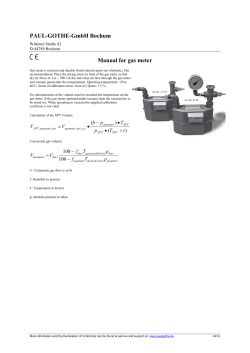


© Copyright 2026