
MT-Series Joker Owner’s Manual 2013 13/15/20
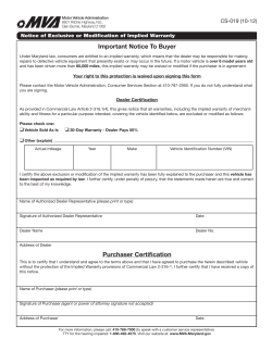
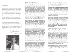
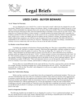
2013 MT-Series Joker Owner’s Manual 13/15/20 200 Knutson St. SE Mapleton, ND 58059 Telephone: (701) 532-1000 Serial Numbers: MT13 SN Earlier – 330013013004 MT15 SN Earlier – 330015013024 MT20 SN Earlier – 330020013015 Fax: (701) 532-1101 Email: [email protected] Web: www.horsch.com 1|Page 2|Page 3|Page Contents Safety and Guidelines ................................................................................................................................... 8 Machine Registration .................................................................................................................................... 8 Warranty Guidelines ..................................................................................................................................... 9 Machine Registration Form: Customer Copy .............................................................................................. 11 Machine Registration Form: Dealer Copy ................................................................................................... 13 Machine Registration Form: HORSCH’s Copy ............................................................................................. 15 Delivery Form: DEALERS’s Copy .................................................................................................................. 17 Product Specification .................................................................................................................................. 19 In These Operating Instructions .................................................................................................................. 20 Authorized Operators ............................................................................................................................. 20 Protective Clothing ................................................................................................................................. 20 Information Regarding Safety ..................................................................................................................... 21 Safety Symbols on the Machine: ............................................................................................................ 21 Operational Safety .................................................................................................................................. 22 Road Traffic Safety .................................................................................................................................. 22 Accident Prevention ................................................................................................................................ 22 Hitching/Unhitching .................................................................................................................................... 23 Changing Implements ............................................................................................................................. 23 In Operation ................................................................................................................................................ 23 Service and Maintenance............................................................................................................................ 23 Correct Calculation of Ballasting ................................................................................................................. 25 Data for calculation: ................................................................................................................................ 25 Formulas: ................................................................................................................................................ 26 Table:....................................................................................................................................................... 27 Technical Data ............................................................................................................................................. 28 Settings/Operation...................................................................................................................................... 29 Ballast Kit..................................................................................................................................................... 30 Hitching/Unhitching the Machine............................................................................................................... 31 Hitching-up:............................................................................................................................................. 31 Parking: ................................................................................................................................................... 31 4|Page RollFlex Packer ............................................................................................................................................ 32 Setup Procedure ......................................................................................................................................... 33 On hard level surface: ............................................................................................................................. 33 In Field Setup: ......................................................................................................................................... 33 Machine Adjustment................................................................................................................................... 34 Depth Setting .............................................................................................................................................. 35 Maintenance and Servicing......................................................................................................................... 36 Cleaning................................................................................................................................................... 36 Maintenance Periods .............................................................................................................................. 36 Storage .................................................................................................................................................... 36 Lubricating Machine ............................................................................................................................... 37 Hygiene ................................................................................................................................................... 37 Exposure to Lubricants............................................................................................................................ 37 Service ..................................................................................................................................................... 37 Maintenance Schedule ............................................................................................................................... 38 Lubrication Points ....................................................................................................................................... 39 Troubleshooting .......................................................................................................................................... 40 Bolt Tightening Torques - Metric Bolts ....................................................................................................... 41 Bolt Tightening Torques - Imperial Bolts .................................................................................................... 42 Notes: .......................................................................................................................................................... 43 5|Page 6|Page 7|Page Safety and Guidelines Safety is YOUR responsibility! READ AND UNDERSTAND THIS MANUAL BEFORE YOU OPERATE THIS MACHINE. Learn how to operate and service your machine correctly. Failure to do so could result in personal injury and/or equipment and property damage. HORSCH will not accept any responsibility for any damage or malfunctions resulting from failure to comply with the Operator’s Manual. If the information found in this manual is not completely understood or if there are any questions, contact HORSCH Customer Service. HORSCH cares about your safety! This machine is designed to provide maximum possible safety; but no machine design can prevent operator error or carelessness. The Operator’s Manual provides instructions for the safe operation and maintenance of this machine. Make sure the machine is in good operation condition. Check service schedule in book. This manual should be considered a permanent part of your machine and should remain with the machine if you no longer own it. Right hand and left hand are determined by facing the direction of forward travel respectively. HORSCH reserves the right to alter illustrations as well as technical data and weights contained in this manual at any time without notice. This data is the property of HORSCH. All use and/or reproduction not specifically authorized by HORSCH are prohibited. All information, illustrations and specifications in this manual are based on the latest information available at the time of publication. The right is reserved to make changes at any time without notice. Some illustrations may show optional equipment. Illustrations may show shields, guards, etc., opened or removed. All shields, guards, etc. must be in place during operation. Machine Registration Please complete the Machine Registration Form on the next few pages and return to HORSCH. Accurately record all the numbers to help in tracing the machine. Your dealer needs these numbers when you order parts. NO WARRANTY CLAIMS WILL BE ACCEPTED IF THIS MACHINE REGISTRATION IS NOT RETURNED. The warranty period begins on the date of delivery. 8|Page Warranty Guidelines 1. The period of warranty for material defects relating to HORSCH products will be 12 months. In the case of written deviations from the statutory provisions, these agreements shall apply. They shall become effective upon delivery of the machine to the end customer. All wear item parts are excluded from the warranty. These parts include but are not limited to disc blades and Rollflex packer tongues. 2. Warranty claims must be submitted to the HORSCH Customer Service Department in Andover, SD via your dealer. It is only possible to process claims which have been completed correctly and submitted no later than four weeks after the damage occurred. 3. In the case of deliveries made under the warranty which are subject to the return of the old parts, the warranty claim, together with the old parts, must be returned to HORSCH within 4 weeks after the damage occurred. 4. In the case of deliveries made under the warranty, which are not subject to the return of the old parts, these parts must be kept for the purpose of further decisions for a period of four weeks after receipt of the warranty claim. 5. Warranty repairs to be carried out by outside companies, or repairs which are expected to take more than 2 working hours, must be approved in advance with HORSCH Customer Service Department. HORSCH LLC 14118 414th Ave Andover, SD 57422 USA (605) 298-5663 www.horschanderson.com www.horsch.com 9|Page 10 | P a g e Machine Registration Form: Customer Copy No Warranty Claims will be accepted if this Machine Registration Form is not returned! To: Horsch LLC 14118 414th Ave. Andover, SD 57422 Machine Type: ......................................................... Additional Equipment: ........................................... Serial Number: ........................................................ Delivery Date: ........................................................ Operator’s Manual and Parts Book: January 1st, 2013. I hereby confirm receipt of the Operator’s Manual and Parts Book for the above mentioned machine. I have been instructed and informed by a HORSCH Service Technician / Dealer about the operation and functions of the machine, as well as about the safety requirements. ............................................................................... Name of the Service Technician Dealer Customer Name: .............................................................. Name:.................................................................... Address: ………………………………………….. Address: ………………………………………………. Postal Code: .................................................... Postal Code:........................................................... Location: ........................................................... Location: ................................................................ Tel: .................................................................. Tel: ........................................................................ Fax: .................................................................. Fax: ...................................................................... E-mail: .............................................................. E-mail: .................................................................. Customer No: ................................................... Customer No: ....................................................... I am aware that a Warranty Claim will only be valid if, after the receipt of the machine, this form has been fully completed, signed and returned to the company HORSCH. ............................................................................. .............................................................................. Place, Date Customer’s Signature Note: After Signing, remove and/or copy this page. Keep signed delivery checklist in machine file at the dealership. 11 | P a g e 12 | P a g e Machine Registration Form: Dealer Copy No Warranty Claims will be accepted if this Machine Registration Form is not returned! To: Horsch LLC 14118 414th Ave. Andover, SD 57422 Machine Type: ......................................................... Additional Equipment: ........................................... Serial Number: ........................................................ Delivery Date: ........................................................ Operator’s Manual and Parts Book: January 1st, 2013. I hereby confirm receipt of the Operator’s Manual and Parts Book for the above mentioned machine. I have been instructed and informed by a HORSCH Service Technician / Dealer about the operation and functions of the machine, as well as about the safety requirements. ............................................................................... Name of the Service Technician Dealer Customer Name: .............................................................. Name: ................................................................... Address: ………………………………………….. Address: ………………………………………………. Postal Code: .................................................... Postal Code: .......................................................... Location: ........................................................... Location: ................................................................ Tel: .................................................................. Tel: ........................................................................ Fax: .................................................................. Fax: ...................................................................... E-mail: .............................................................. E-mail: .................................................................. Customer No: ................................................... Customer No: ........................................................ I am aware that a Warranty Claim will only be valid if, after the receipt of the machine, this form has been fully completed, signed and returned to the company HORSCH. ............................................................................. .............................................................................. Place, Date Customer’s Signature Note: After Signing, remove and/or copy this page. Keep signed delivery checklist in machine file at the dealership. 13 | P a g e 14 | P a g e Machine Registration Form: HORSCH’s Copy No Warranty Claims will be accepted if this Machine Registration Form is not returned! To: Horsch LLC 14118 414th Ave. Andover, SD 57422 Machine Type: ......................................................... Additional Equipment: ........................................... Serial Number: ......................................................... Delivery Date: ........................................................ Operator’s Manual and Parts Book: January 1st, 2013. I hereby confirm receipt of the Operator’s Manual and Parts Book for the above mentioned machine. I have been instructed and informed by a HORSCH Service Technician/Dealer about the operation and functions of the machine, as well as about the safety requirements. ............................................................................... Name of the Service Technician Dealer Customer Name: .............................................................. Name:.................................................................... Address: …………………………………………… Address: ………………………………………………. Postal Code: ................................................... Postal Code:........................................................... Location: .......................................................... Location: ................................................................ Tel: .................................................................. Tel: ......................................................................... Fax: .................................................................. Fax: ........................................................................ E-mail: .............................................................. E-mail: .................................................................... Customer No: ................................................... Customer No: ......................................................... I am aware that a Warranty Claim will only be valid if, after the receipt of the machine, this form has been fully completed, signed and returned to the company HORSCH. ............................................................................. .............................................................................. Place, Date Customer’s Signature Note: After Signing, remove and/or copy this page. Keep signed delivery checklist in machine file at the dealership. 15 | P a g e 16 | P a g e Delivery Form: DEALERS’s Copy At the time the machine is delivered, the following checklist is a reminder of information which should be conveyed directly to the customer. Check off each item as it is fully explained to customer. [ ] Make the customer aware of all safety precautions that must be exercised while using this machine. Point out all Warning and Caution safety labels/decals on the machine. [ ] Point out the location of the Serial Number Tag (product identification numbers), for future reference of the machine. [ ] Give the Operator’s Manual to the customer. Encourage customer to read the manual in its entirety. [ ] Explain all operating adjustments. [ ] Review recommended procedures for attaching and detaching machine from tractor. [ ] Make the customer aware of all safety precautions that must be observed when transporting the machine in field and on public roads. [ ] When the machine is transported on a road or highway at night, or during the day, accessory lighting and devices should be used for adequate warning to operators of other vehicles. In this regard, tell the customer to check local governmental regulations. The machine should be equipped with road lighting and slow moving vehicle sign. [ ] Explain to the customer that the life expectancy of this or any other machine depends on regular lubrication as directed in the Operator’s Manual. Follow all maintenance and lubrication schedules for the machine. [ ] Discuss with the customer the use of proper tools and equipment for service of the machine. [ ] Have customer record Serial Number(s) in the Product Specification section. [ ] To the best of my knowledge, this machine has been delivered ready for field use and the customer has been fully informed as to proper operation and care. Signed: ................................................................................. (Customer) Signed: ................................................................................. (Dealer Representative) Date: ..................................................................................... 17 | P a g e 18 | P a g e Product Specification Each machine manufactured and assembled is serialized and provided a number for tracking purposes. There is a model number, which is the category for product family of the machine, and there is a serial number. The serial number may also be known as, or part of, a Product Identification Number. This number is a formulated number which details the machines build information for tracking purposes and easy identification later during time of service, maintenance and replacement part ordering. The Serial number, along with Model number of the machine, can be found on the Serial Number Tag. HORSCH LLC has placed a Serial Number Tag (reference picture below) on the machine with the above mentioned information. It is located on the main frame cross member tube directly behind the front hitch, just off center towards the left hand side of each machine. Record the Model and Serial number of the machine below. Retain this page for customer use only! For future reference, the information will be used whenever the machine is being serviced, for ordering replacement parts or when requesting information for the machine such as replacement Owner’s Manual or a Parts Catalog. Be sure to provide both, the model number and serial number, when contacting your dealer, for better assistance and quicker support of your machine. HORSCH LLC Serial Number Tag Date of Purchase: ___________________________ Dealer Information: Name: ______________________________ Address: _____________________________ Phone: _______________________________ 19 | P a g e In These Operating Instructions The operating instructions distinguish between three different types of warning and safety instructions. The following graphic symbols are used: Important instructions! If there is a risk of injury! If there is a risk to life and limb! It is important that all the safety instructions contained in these operating instructions and all the warning signs on the machine are read thoroughly and understood prior to operation of the machine. Ensure that the warning signs are legible and replace any signs that are missing or damaged. These instructions must be followed in order to prevent accidents. Inform other users of the warnings and safety instructions and the location of this Owner’s Operators Manual. Do not carry out any operations which may affect the safe use of the machine. Authorized Operators Only those persons who have been authorized and instructed by the operator may operate the Machine. Operators must be at least 16 years of age. The operator must hold a valid driving license. They are responsible for third parties in the operating area. The person in charge must: Make the operating instructions available to the operator. Ensure that the operator has read and understood the operating instructions. The operating instructions are a component part of the machine. Protective Clothing For operation and maintenance of this machine, you will need: Snug fitting clothing; no loose articles or strings. Safety gloves and goggles to protect against dirt and sharp edged machine parts. 20 | P a g e Information Regarding Safety The following warnings and safety instructions apply to all sections in these operating instructions. Safety Symbols on the Machine: Read and adhere to the operating instructions before starting up the machine! Stay clear of swinging area of retractable and extendible machine parts! Switch the engine off and pull out the key before starting maintenance and repair work! Never reach into areas where there is a risk of crushing, as long as parts could still be moving! Watch out for fluids spraying out under high pressure, follow the operating instructions! It is only permitted to remain in the danger zone if the safety support is in place! When hitching up the drill and when operating the hydraulic system, no persons should be between the machines! No passengers are allowed to ride on the machine! Do not climb on rotatable parts. Use mounting steps provided for this purpose! Lifting hook; attach lifting tackle (chains, ropes, etc.) here when performing loading work! 21 | P a g e Operational Safety The machine must only be put into operation after receiving instructions by employees of the authorized dealer or a HORSCH employee. The Machine Registration Form has to be completed and returned to HORSCH. Road Traffic Safety The valid road traffic regulations are to be observed when travelling on public roads, paths and areas. Do not exceed the maximum permissible transportation widths and heights and install road lighting equipment, warnings and safety covers where necessary. Do not exceed the permissible axle loads, tire carrying capacities and total weights, in order to ensure sufficient steering and braking capabilities. Handling is affected by the implement connected. It is important to take into account the large overhang and the centrifugal mass of the implement, particularly when cornering. The whole machine is to be cleaned of soil that has been collected before travel on public roads. Passengers are strictly forbidden to ride on the machine. Accident Prevention In addition to the operating instructions, it is important to observe the accident prevention regulations specified by agricultural trade associations! 22 | P a g e Hitching/Unhitching There is risk of injury to persons when hitching/unhitching the machine to the three-point hitching device of the tractor. • Secure the machine against rolling away. • Take special care when reversing the tractor. Never stand between tractor and machine. • Only park the machine on a firm and level surface. For further information see Page 31. Changing Implements • Secure the machine against unintended rolling! • Secure lifted frame parts, under which you will be working, with suitable supports! • Caution! Danger of injury caused by protruding parts (tines, discs)! • Do not use the packer or other rotating parts when climbing onto the machine. These could start to rotate and you could fall and be seriously injured. In Operation • Check the area around the machine (for children!) before setting off and starting operation of the machine. Ensure sufficient visibility! • Stay clear of the operating range of hydraulically operated parts. • Passengers are not allowed to ride on the machine during operation! Service and Maintenance • Ensure that regular tests and inspections are always carried out to schedule, as specified in the operating instructions. • Prior to performing maintenance and servicing work, ensure that the machine is positioned on firm, level ground and that it is properly secured against rolling away. • Prior to working on the electrical system, disconnect it from the electric power supply. • Retighten screwed connections which had been loosened during servicing and maintenance work. For further Service and maintenance information see Page 35. Do not wash new machines with a steam-jet or high-pressure cleaner. The paint takes approximately 3 months to cure and could thus be damaged if this time has not yet expired. 23 | P a g e 24 | P a g e Correct Calculation of Ballasting The permissible total weight, the permissible axle loads and the load bearing capacity of the tires must not be exceeded when attaching implements in the 3-point linkage at front and rear. The front axle of the tractor must always be loaded with at least 20 % of the tractor’s curb weight! Before transportation on public roads you must make sure that the tractor is not overloaded and suitable for this implement. Data for calculation: All specified weight in (lbs.) All specified dimensions in (feet) TL - Curb weight of tractor TV - Front axle load of empty tractor TH - Rear axle load of empty tractor GH - Total weights of rear implement GV - Total weight of front implement a - Distance from center of gravity of front implement (front ballast) to middle of front axle b - Tractor wheel base c - Distance from middle of rear axle to middle tractor link arm ball d - Distance from middle of tractor link arm ball to center of gravity of rear implement (rear ballast) x - Information of tractor manufacturer for min. rear ballasting. If no information is available, enter 0.45. 25 | P a g e Formulas: 1. Calculation of minimum front ballasting with rear implement: Enter the result into the table. 2. Calculation of minimum rear ballasting with front implement: Enter the result into the table. 3. Calculation of the real front axle load: Enter the result of the calculated actual front axle load and the permissible front axle load from the operating instruction of the tractor into the table. 4. Calculation of the actual total weight: Enter the result of the calculated actual total weight and the permissible total weight from the operating instruction of the tractor into the table. 26 | P a g e Table: The calculated values must be lower than or equal with the permissible values. 27 | P a g e Technical Data Joker MT-13 Working width:..................................... 13 Ft. Transport width:................................... 13 Ft. Weight:................................................. 6458 Lbs. * Number of discs: ................................. 24 Hitching: Hitching:................................................. Three-point Cat III; QuickHitch Compatible Road lighting equipment:...................... 12 V Power requirements:.............................. 120-160 HP Joker MT-15 Working width:...................................... Transport width:.................................... Weight:.................................................. Number of discs: ................................... Hitching: Hitching:................................................ Road lighting equipment:..................... Power requirements:............................ 15 Ft. 15 Ft. 7585 Lbs.* 32 Three-point Cat III; QuickHitch Compatible 12 V 160-180 HP Joker MT-20 Working width:....................................... 20 Ft. Transport width:..................................... 20 Ft. Weight:.................................................. 9635 Lbs.* Number of discs: ................................... 32 Hitching: Hitching:................................................ Three-point Cat III ; QuickHitch Compatible Road lighting equipment:..................... 12 V Power requirements:............................ 180-240 HP *All weights include 1600 Lb Ballast Kit. 28 | P a g e Settings/Operation Cultivation tools: The serrated coulter discs cut the harvest residues and the soil and mix the residues in to the soil down to working depth. Joker CT Maintenance: The bearings are oil filled and therefore, maintenance free. Disc feeder bearing. Check the discs regularly for clearance, leaks, tightness and unrestricted rotation. Notes on cleaning: The mechanical seals of the disc hubs are very sensitive. If water has entered them and the machine is then parked over a longer period of time, damage may occur. This can cause corrosion, and both mechanical seal rings may stick together. The mechanical seal rings will then rotate around the O-ring and damage it. Oil would run out of the hub and the bearing would be damaged after a short while with no lubrication. • Bearings must therefore not be cleaned with high pressure cleaning equipment. • Before longer periods of rest the bearing locations should be sprayed with a rust dissolver or similar. 29 | P a g e Before resuming operation the discs should be turned by hand and checked for unrestricted rotation. The disc hub is oil filled as mentioned above. If the seals or O-rings are damaged and further service is required, replace the seals and O-rings and fill the hub with 1.3 ounces 75w140 synthetic gear oil. Ballast Kit Machine comes with Ballast Kit. • Add and remove weights as needed to achieve desired weight for operation. • Weight is added to help machine go in ground. • Each individual weight ballast weighs 100 lbs. Check to make sure Ballast Kit is secure before operation. 30 | P a g e Hitching/Unhitching the Machine Nobody is to remain between the tractor and the machine when hitching up and unhitching. Hitching-up: • Hitch up the machine to the three-point hitch on the tractor. • Connect the road lighting equipment plug and check the function. • Lift the machine. Do not transport the machine in a position higher than necessary. Parking: • Only park the machine on a firm and level surface. • Disconnect the road lighting equipment plug. • Unhitch the machine. ATTENTION - Cat III QuickHitch Compatible 31 | P a g e RollFlex Packer RollFlex can be attached as a rear packer on the machine. While in use in the field the machine always travels on the packer. Due to the weight of the machine a high consolidation and a fine crumbly, level surface is achieved. RollFlex Packer With cohesive soils the packers may pick up more soil and thus become considerably heavier. This can overload components or soil the roads during transportation. Packers must therefore, always be cleaned before road transportation if they have picked up soil. 32 | P a g e Setup Procedure On hard level surface: 1. Unhook tractor and implement with Rollflex upper depth control pins removed. 2. Set tractor lower link arms to allow lateral float. 3. Adjust lower links so both are at same height. 4. Raise the three-point hitch so that the lower links are just touching the lower mounting pins on the implement. (Record three-point lever location.) 5. Lower the three-point of the tractor to an even distance from the lower mounting pins (i.e. 2”) and record lever location. This will provide the correct depth setting in the field and give the operator a scale by which to adjust depth from. 6. Attach the tractor to the implement, placing the three-point hitch so that it’s at the position found in Step 4. 7. Adjust top link so that it’s tight. In Field Setup: 1. Start a pass in the field and adjust to desired working depth. 2. Continue pass in the field and observe the three-point hitch movement side-to-side. Stop the tractor with the implement still in the ground and observe three-point. If the implement is pulled tight to one sway block, adjust top link to correct. The implement is leveled correctly when the three-point “floats” side-to-side when at working speed and depth in the field. 3. Install Rollflex depth control pins at a setting that allows for constant pin contact with packer frame. Do not allow Rollflex frame to hammer against pins while operating; this will cause excessive wear on the frame and pins and provide inconsistent performance. 4. Continue on the same pass in the field and adjust top link accordingly to minimize side draft. 33 | P a g e Machine Adjustment 1. Adjust length of lower link arms so machine is level side-to-side. 2. Remove lateral float locks from tractor lower link arms. This will allow the machine to follow the ground contour independent of the tractor. 3. Place hitch sway blocks to prevent side movement of arms when working. 4. Place packer depth control pins in desired locations. 5. Lower hitch and slowly operate (5-6 mph) machine in field. Adjust hitch to obtain desired working depth. 6. Set hitch stop point at desired depth. This will prevent machine from working deeper in varying soil conditions. 7. When slowly operating machine, observe machine and hitch lower link arms to determine which direction the machine is pulling. Adjust top link arm until machine pulls straight behind tractor. Proper adjustment is achieved when lower link arms do not contact sway blocks or slightly contacts sway blocks in an alternating motion. 8. Observe packer depth control pins; when operating machine the packer arms should be tight to the pins or not contacting arms at all. Arms must not repeatedly contact pins throughout field or excessive wear may occur to pins and arms. Adjust pin location so that this does not occur. 9. Increase operation to desired speed (8-10 mph) and make fine adjustments as necessary. With cohesive soils the machine may accumulate material and become considerably heavier. This can overload components or create a hazard on the roads during transportation. Machine must therefore, always be cleaned before road transportation. 34 | P a g e Depth Setting In working position, the packer carries the machine at the rear. The inclination of the machine is determined by the front three-point hitch. In the field, lower the machine and switch the linkage control unit to float position. In working position, use the pins to adjust the packer height, until the desired working depth is reached. In working position, adjust the inclination of the machine on the upper link, until it is set horizontally. The machine must be level in order to operate properly! Rear Depth Setting 35 | P a g e Maintenance and Servicing Observe the safety instructions for maintenance and servicing. Your machine has been designed and constructed for maximum power, efficiency and user-friendliness according to a multitude of operating conditions. Your machine has been checked at the factory and by your appointed dealer prior to delivery in order to determine that the machine is in perfect condition. The recommended maintenance and servicing schedule should be carried out at regular intervals in order to maintain failure-free operation. Cleaning The recommended cleaning and maintenance work should be carried out at regular intervals in order to maintain operational availability and guarantee optimum performance. The bearings should not be cleaned with a high pressure cleaner or direct water jet. The seals and bearings are not waterproof under high pressure. Maintenance Periods The maintenance intervals are determined by various different factors. Various operating, weather and soil conditions as well as working speeds affect the maintenance intervals, but also the quality of the lubricants and cleaning agents used determines the time interval required until the next period of maintenance work. The specified maintenance intervals can therefore only be regarded as an indication. The intervals of maintenance work affected have to be adjusted to suit the conditions should there be any deviations from normal operating conditions. Regular maintenance forms the basis for a serviceable machine. Serviced machines lower the risk of malfunctions and guarantee the efficient application and operation of machines. Storage Should the machine not be used for a longer period of time, follow these steps: If possible, store the machine under a roofed area. Protect the machine against rust. Only spray with biologically degradable oils, i.e. rapeseed oil. 36 | P a g e Lubricating Machine The machine should be lubricated regularly and after every pressure wash. This ensures operational reliability and reduces the costs of repair work and down times. Hygiene When used according to regulations, lubricants and mineral oil products present no danger to health. You should, however, avoid longer contact to the skin and not breathe in any fumes. Exposure to Lubricants CAUTION: Avoid direct contact with oils by wearing gloves or protective creams. Thoroughly wash off traces of oil on the skin with warm water and soap. Do not clean your skin with petrol, diesel fuel or other solvents. Oil is poisonous. You should immediately visit your doctor if you have swallowed oil. • Ensure that lubricants are kept out of reach of children. • Never store lubricants in open or unlabeled containers. • Avoid skin contact with oily clothes. Change dirty clothing. • Never keep oily cloths in your pockets. • Dispose of oily shoes as hazardous waste. • Rinse oil that has splashed into your eyes with clean water and visit your doctor, if necessary. • Absorb spilled oil with suitable bonding agents and dispose of properly. • Never extinguish oil fires with water. Only use permissible and suitable extinguishing agents and wear breathing apparatus. Oily waste and waste oil have to be disposed of according to the legal regulations. Check with your local Hazardous Waste Management facility. Service HORSCH hopes you are completely satisfied with your machine and the HORSCH company itself. Please contact your distribution partner or authorized dealer in the event of a problem. The customer service employees of our distribution partners and customer service employees of the company HORSCH are available for your support. Please help us solve any technical faults as soon as possible. Provide the customer service staff with the following details in order to prevent unnecessary queries. • Customer No. • Name of customer service advisor • Name and address • Machine model and serial number • Purchase date and operating hours • Type of problem 37 | P a g e Maintenance Schedule After the first few operating hours: All screwed and plug-in connections Lubricate Packer Coulter discs Frame and connecting parts Hydraulic system and components Road lighting Complete machine Maintenance Schedule Work instructions: Check for tightness and tighten screw connections In operation Lubricate the safety pins Lubricate the packer shafts Check condition, bearing and fastening Check for condition, tight fit and wear Check oil bath bearing for leak tightness and wear Check condition and tight fit Leak, tightness, fastening and chafing Condition, function and cleanliness At the end of the season Carry out service and cleaning work Interval: 40 hours 40 hours 40 hours Daily Daily Prior to use Prior to use Bolts that need to be checked periodically: 38 | P a g e Lubrication Points MT Series Joker –Lubrication Points (Rear RollFlex Packer pivot pins – x2) RollFlex Depth Setting Pins (Not greasable – reference only) 39 | P a g e Troubleshooting Problem Cause Solution Machine does not track straight. Machine does not stop at desired depth. Machine acts erratically, does not maintain consistent depth. Entire machine plugs when running. Machine is not level front to back. Hitch stop point not set correctly. Draft control not set correctly. Adjust hitch top link. Change packer depth stop location. Refer to tractor operator manual for correct operation. Refer to tractor operator manual for correct operation. Ground speed too slow; working depth too deep. Increase ground speed up to 10 mph. Reduce tillage depth. 40 | P a g e Bolt Tightening Torques - Metric Bolts 41 | P a g e Bolt Tightening Torques - Imperial Bolts 42 | P a g e Notes: Go to Top 43 | P a g e * 200 Knutson St. SE, Mapleton ND 58059 USA * 701.532.1000 * www.horsch.com PN 04519100 Ver. 7 04/2014 44 | P a g e


© Copyright 2026