
M20 (Diesel) Scrubber−Sweeper Operator Manual
M20
(Diesel)
Scrubber−Sweeper
Operator Manual
R
The Safe Scrubbing AlternativeR
ESR Extended Scrub System
TennantTrueR Parts
Hygenic R Fully Cleanable Tanks
FloorSmartR Integrated Cleaning System
IRISR a Tennant Technology
North America / International
For the latest parts manuals and other
language Operator manuals, visit:
www.tennantco.com/manuals
Home
Find... Go To..
331410
Rev. 13 (9-2014)
*331410*
INTRODUCTION
This manual is furnished with each new model. It provides necessary operation and maintenance instructions.
Read this manual completely and understand the machine before operating or servicing it.
This machine will provide excellent service. However, the best results will be obtained at minimum costs if:
The machine is operated with reasonable care.
The machine is maintained regularly - per the machine maintenance instructions provided.
The machine is maintained with manufacturer supplied or equivalent parts.
PROTECT THE ENVIRONMENT
Please dispose of packaging materials,
old machine components and fluids in
an environmentally safe way according
to local waste disposal regulations.
MACHINE DATA
Please fill out at time of installation for future
reference.
Model No. −
Always remember to recycle.
Serial No. −
Installation Date −
INTENDED USE
The M20 is an industrial rider machine designed to sweep/scrub hard surfaces (concrete, asphalt, stone, synthetic,
etc). Typical applications include industrial warehouses, manufacturing facilities, distribution facilities, stadiums,
arenas, convention centers, parking facilities, transportation terminals, and construction sites. Do not use this
machine on soil, grass, artificial turf, or carpeted surfaces. This machine can be used both indoors and outdoors, but
ensure there is adequate ventilation if used indoors. This machine is not intended for use on public roadways. Do not
use this machine other than described in this Operator Manual.
Tennant Company
PO Box 1452
Minneapolis, MN 55440
Phone: (800) 553−8033 or (763) 513−2850
www.tennantco.com
CALIFORNIA PROPOSITION 65 WARNING:
Engine exhaust from this product contains chemicals known to the State of California to cause cancer,
birth defects, or other reproductive harm.
Thermo−Sentry, Touch−N−Go, 1−STEP, Clean−Wedge, Variable Drain Valve, EasyOpen, Grip−n−Go, MaxPro, Dura−Track, SmartRelease,
InstantAccess, Duramer, FaST−PAK, ErgoSpace and Lower Total Cost of Ownership are trademarks of Tennant Company.
Specifications and parts are subject to change without notice.
Original Instructions, copyright 2006 − 2014 TENNANT Company, Printed in U.S.A.
Home
Find... Go To..
CONTENTS
CONTENTS
Page
Important Safety Instructions − Save These
Instructions . . . . . . . . . . . . . . . . . . . . . . . . . . . . . 3
Operation . . . . . . . . . . . . . . . . . . . . . . . . . . . . . . . 7
Machine Components . . . . . . . . . . . . . . . . . . 7
Controls And Instruments . . . . . . . . . . . . . . . 8
Touch Panel . . . . . . . . . . . . . . . . . . . . . . . . . . 9
Symbol Definitions . . . . . . . . . . . . . . . . . . . . . 10
Operation Of Controls . . . . . . . . . . . . . . . . . . 11
Charging System Indicator . . . . . . . . . . . 11
Engine Oil Pressure Indicator . . . . . . . . 11
Check Engine Indicator
(S/N 000000−002885) . . . . . . . . . . . . 11
Glow Plug Light (Preheat) . . . . . . . . . . . . 11
Parking Brake Indicator (Option) . . . . . . 11
Setting The Engine Speed . . . . . . . . . . . 12
Side Brush (Option) . . . . . . . . . . . . . . . . . 12
Fuel Indicator . . . . . . . . . . . . . . . . . . . . . . 12
Hour Meter . . . . . . . . . . . . . . . . . . . . . . . . 13
Supervisor Control Buttons . . . . . . . . . . . 13
Operating Lights . . . . . . . . . . . . . . . . . . . . 13
Hazard Light (Option) . . . . . . . . . . . . . . . 13
Operator Seat . . . . . . . . . . . . . . . . . . . . . . 14
Seat Belts . . . . . . . . . . . . . . . . . . . . . . . . . 14
Steering Column Tilt Knob . . . . . . . . . . . 14
Brake Pedal . . . . . . . . . . . . . . . . . . . . . . . 15
Parking Brake Pedal . . . . . . . . . . . . . . . . 15
Directional Pedal . . . . . . . . . . . . . . . . . . . 15
Squeegee Protectors (Option) . . . . . . . . 15
How The Machine Works . . . . . . . . . . . . . . . 16
Brush Information . . . . . . . . . . . . . . . . . . . . . 17
While Operating The Machine . . . . . . . . . . . 17
Pre−Operation Checklist . . . . . . . . . . . . . . . . 18
Starting The Machine . . . . . . . . . . . . . . . . . . 19
Turning Off The Machine . . . . . . . . . . . . . . . 19
Filling The Solution Tank . . . . . . . . . . . . . . . . 20
Foam Scrubbing (FaST Mode) / Ec−H2o
Scrubbing (Ec−H2o Mode) . . . . . . . . . . . 20
Conventional Scrubbing Mode . . . . . . . . . . . 20
Es (Extended Scrub) Mode With Auto−Fill 21
Es (Extended Scrub) Mode −
Manually Filling Tanks . . . . . . . . . . . . . . . 21
Setting Scrub Modes . . . . . . . . . . . . . . . . . . . 22
Setting FaST Mode . . . . . . . . . . . . . . . . . 22
Setting Es (Extended Scrub) Mode . . . . 22
Setting Ec−H2o Mode . . . . . . . . . . . . . . . 22
Setting Brush Pressure . . . . . . . . . . . . . . 22
Setting Solution Flow . . . . . . . . . . . . . . . . 23
Conventional, FaST, And Ec−H2o
Solution Flow . . . . . . . . . . . . . . . . . . . . 23
Es (Extended Scrub) Solution Flow . . . 23
Scrubbing . . . . . . . . . . . . . . . . . . . . . . . . . . . . . 24
Double Scrubbing . . . . . . . . . . . . . . . . . . . . . 25
Water Pickup Mode (No Scrubbing) . . . . . . 26
Sweeping . . . . . . . . . . . . . . . . . . . . . . . . . . . . . 26
Emptying The Hopper . . . . . . . . . . . . . . . . . . 28
Page
Engaging Hopper Support Pin . . . . . . . . . . . 29
Disengaging Hopper Support Pin . . . . . . . . 29
Removing The Hopper Dust Filter . . . . . . . . 30
Cleaning The Hopper And Debris Screen . 31
Draining And Cleaning The Recovery Tank 32
Draining The Recovery Tank With
The Drain Hose . . . . . . . . . . . . . . . . . . . . 32
Draining The Recovery Tank With
The Drain Plug . . . . . . . . . . . . . . . . . . . . . 34
Draining And Cleaning The Solution Tank . 35
Fault Indicator(S) . . . . . . . . . . . . . . . . . . . . . . 37
Conditions / Warnings . . . . . . . . . . . . . . . . . . 38
Options . . . . . . . . . . . . . . . . . . . . . . . . . . . . . . 39
Spray Nozzle (Option) . . . . . . . . . . . . . . . 39
Vacuum Wand (Option) . . . . . . . . . . . . . . 40
Machine Troubleshooting . . . . . . . . . . . . . . . 41
Maintenance . . . . . . . . . . . . . . . . . . . . . . . . . . . . . 43
Maintenance Chart . . . . . . . . . . . . . . . . . . . . 44
Lubrication . . . . . . . . . . . . . . . . . . . . . . . . . . . 46
Engine Oil . . . . . . . . . . . . . . . . . . . . . . . . . . . . 46
Squeegee Caster Bearings . . . . . . . . . . . . . 46
Front Wheel Support Bearing . . . . . . . . . . . 46
Steering Cylinder Bearing . . . . . . . . . . . . . . . 46
Hopper Lift Arm Pivots . . . . . . . . . . . . . . . . . 47
Hopper Door Pivots . . . . . . . . . . . . . . . . . . . . 47
Lift Arm Latch . . . . . . . . . . . . . . . . . . . . . . . . . 47
Torque Tubes . . . . . . . . . . . . . . . . . . . . . . . . . 47
Hydraulics . . . . . . . . . . . . . . . . . . . . . . . . . . . . 48
Hydraulic Fluid . . . . . . . . . . . . . . . . . . . . . 49
Hydraulic Hoses . . . . . . . . . . . . . . . . . . . . 49
Engine . . . . . . . . . . . . . . . . . . . . . . . . . . . . . . . 50
Cooling System . . . . . . . . . . . . . . . . . . . . 50
Air Filter . . . . . . . . . . . . . . . . . . . . . . . . . . . 51
Fuel Filter . . . . . . . . . . . . . . . . . . . . . . . . . 51
Fuel Lines . . . . . . . . . . . . . . . . . . . . . . . . . 51
Priming The Fuel System . . . . . . . . . . . . 52
Engine Belt . . . . . . . . . . . . . . . . . . . . . . . . 52
Battery . . . . . . . . . . . . . . . . . . . . . . . . . . . . . . . 52
Fuses, Relays, And Circuit Breakers . . . . . 53
Relay Panel Fuses And Relays . . . . . . . . . . 53
Engine Harness Fuses And Relays . . . . . . 54
Circuit Breakers (Ec−H2o) . . . . . . . . . . . . . . 54
Cleaning The Hopper Dust Filter . . . . . . . . . 54
Thermo−Sentry . . . . . . . . . . . . . . . . . . . . . . . 55
Main Brushes . . . . . . . . . . . . . . . . . . . . . . . . . 55
Replacing Or Rotating The Main
Brushes . . . . . . . . . . . . . . . . . . . . . . . . 55
Checking The Main Brush Pattern . . . . 57
Adjusting The Main Brush Taper . . . . . . 58
Adjusting The Main Brush Width . . . . . . 58
Side Brush (Option) . . . . . . . . . . . . . . . . . . . . 59
Replacing The Side Brush . . . . . . . . . . . 59
1
M20 Diesel 331410 (3−2013)
Home
Find... Go To..
CONTENTS
Page
FaST System . . . . . . . . . . . . . . . . . . . . . . . . . . 60
Replacing The FaST−Pak Carton . . . . . 60
Cleaning The FaST Supply Hose
Connector . . . . . . . . . . . . . . . . . . . . . . 61
Cleaning The FaST System
Filter Screen . . . . . . . . . . . . . . . . . . . . . 61
Cleaning The FaST System Air Pump
Filter (S/N 000000 − 002532) . . . . . . 61
Replacing The FaST System Filters
(S/N 002533−
) . . . . . . . . . . . . . 61
Ec−H2o Module Flush Procedure . . . . . . . . 62
Cleaning The Ec−H2o Filter Screen . . . 63
Squeegee Blades . . . . . . . . . . . . . . . . . . . . . . 64
Replacing (Or Rotating) The Rear
Squeegee Blades . . . . . . . . . . . . . . . . 64
Replacing Or Rotating The Side
Squeegee Blades . . . . . . . . . . . . . . . . 66
Replacing The Side Brush Squeegee
Blade (S/N 000000−003076) (Option) 68
Replacing Or Adjusting The Side Brush
Squeegee Blade (S/N 003077−
)
(Option) . . . . . . . . . . . . . . . . . . . . . 69
Leveling The Rear Squeegee . . . . . . . . . 70
Adjusting The Rear Squeegee Blade
Deflection . . . . . . . . . . . . . . . . . . . . . . . 71
Skirts And Seals . . . . . . . . . . . . . . . . . . . . . . . 72
Scrub Head Skirt . . . . . . . . . . . . . . . . . . . . . . 72
Recovery Tank Seal . . . . . . . . . . . . . . . . . . . 72
Solution Tank Seals . . . . . . . . . . . . . . . . . . . . 72
Brakes And Tires . . . . . . . . . . . . . . . . . . . . . . 73
Brakes . . . . . . . . . . . . . . . . . . . . . . . . . . . . 73
Tires . . . . . . . . . . . . . . . . . . . . . . . . . . . . . . . 73
Front Wheel . . . . . . . . . . . . . . . . . . . . . . . 73
Propelling Motor . . . . . . . . . . . . . . . . . . . . . . . 73
Pushing, Towing, And Transporting
The Machine . . . . . . . . . . . . . . . . . . . . . . . 74
Pushing Or Towing The Machine . . . . . . 74
Transporting The Machine . . . . . . . . . . . 74
Machine Jacking . . . . . . . . . . . . . . . . . . . . . . 76
Storage Information . . . . . . . . . . . . . . . . . . . . 76
Freeze Protection (Machines Without
Ec−H2o System) . . . . . . . . . . . . . . . . 77
Freeze Protection (Machines With
Ec−H2o System) . . . . . . . . . . . . . . . . 77
Priming The Ec−H2o System . . . . . . . . . 79
Specifications . . . . . . . . . . . . . . . . . . . . . . . . . . . . . 80
General Machine Dimensions/Capacities . 80
General Machine Performance . . . . . . . . . . 80
Hydraulic System . . . . . . . . . . . . . . . . . . . . . . 80
Steering . . . . . . . . . . . . . . . . . . . . . . . . . . . . . . 81
Power Type . . . . . . . . . . . . . . . . . . . . . . . . . . . . 81
Tires . . . . . . . . . . . . . . . . . . . . . . . . . . . . . . . . . . 81
FaST System . . . . . . . . . . . . . . . . . . . . . . . . . . 82
Ec−H2o System . . . . . . . . . . . . . . . . . . . . . . . 82
Machine Dimensions . . . . . . . . . . . . . . . . . . . 83
Index . . . . . . . . . . . . . . . . . . . . . . . . . . . . . . . . . . . 84
2
M20 Diesel 331410 (3−2013)
Home
Find... Go To..
SAFETY PRECAUTIONS
IMPORTANT SAFETY INSTRUCTIONS − SAVE THESE INSTRUCTIONS
The following precautions are used throughout
this manual as indicated in their description:
WARNING: To warn of hazards or
unsafe practices that could result in
severe personal injury or death.
CAUTION: To warn of unsafe practices
that could result in minor or moderate
personal injury.
This machine may be equiped with
technology that automatically communicates
over the cellular network. If this machine will
be operated where cell phone use is restricted
because of concerns related to equipment
interference, please contact a Tennant
representative for information on how to
disable the cellular communication
functionality.
FOR SAFETY:
FOR SAFETY: To identify actions that must be
followed for safe operation of equipment.
The following information signals potentially
dangerous conditions to the operator. Know when
these conditions can exist. Locate all safety
devices on the machine. Report machine
damage or faulty operation immediately.
WARNING: Flammable materials can
cause an explosion or fire. Do not use
flammable materials in tank.
WARNING: Flammable materials or
reactive metals can cause an explosion
or fire. Do not pickup.
WARNING: Moving belt and fan. Keep
away.
WARNING: Engine emits toxic gases.
Serious injury or death can result.
Provide adequate ventilation.
WARNING: Raised hopper may fall.
Engage hopper support pin.
WARNING: Lift arm pinch point. Stay
clear of hopper lift arms.
WARNING: Burn hazard. Hot surface. Do
NOT touch.
CALIFORNIA PROPOSITION 65
WARNING: Engine exhaust from this
product contains chemicals known to
the State of California to cause cancer,
birth defects, or other reproductive
harm.
1. Do not operate machine:
− Unless trained and authorized.
− Unless operator manual is read and
understood.
− Under the influence of alcohol or
drugs.
− While using a cell phone or other
types of electronic devices.
− Unless mentally and physically
capable of following machine
instructions.
− If it is not in proper operating
condition.
− In areas where flammable
vapors/liquids or combustible dusts
are present.
− In areas that are too dark to safely see
the controls or operate the machine
unless operating / headlights are
turned on.
− In areas with possible falling objects
unless equipped with overhead guard.
2. Before starting machine:
− Check machine for fluid leaks.
− Keep sparks and open flame away
from refueling area.
− Make sure all safety devices are in
place and operate properly.
− Check brakes and steering for proper
operation.
3. When starting machine:
− Keep foot on brake and directional
pedal in neutral.
3
M20 Diesel 331410 (3−2013)
Home
Find... Go To..
SAFETY PRECAUTIONS
4. When using machine:
− Use only as described in this manual.
− Do not pick up burning or smoking
debris, such as cigarettes, matches, or
hot ashes.
− Use brakes to stop machine.
− Go slow on inclines and slippery
surfaces.
− Reduce speed when turning.
− Keep all parts of body inside operator
station while machine is moving.
− Use care when reversing machine.
− Move machine with care when hopper
is raised.
− Make sure adequate clearance is
available before raising hopper.
− Do not raise hopper when machine is
on an incline.
− Never allow children to play on or
around machine.
− Do not carry passengers on machine.
− Always follow safety and traffic rules.
− Report machine damage or faulty
operation immediately.
− Follow mixing, handling and disposal
instructions on chemical containers.
− Follow safety guidlines concerning
wet floors.
5. Before leaving or servicing machine:
− Do not park near combustible
materials, dusts, gases, or liquids.
− Stop on level surface.
− Set parking brake.
− Turn off machine and remove key.
6. When servicing machine:
− All work must be done with sufficient
lighting and visibility.
− Avoid moving parts. Do not wear loose
clothing, jewelry and secure long hair.
− Block machine tires before jacking
machine up.
− Jack machine up at designated
locations only. Support machine with
jack stands.
− Use hoist or jack that will support the
weight of the machine.
− Do not power spray or hose off
machine near electrical components.
− Disconnect battery connections before
working on machine.
− Avoid contact with battery acid.
− Avoid contact with hot engine coolant.
− Do not remove cap from radiator when
engine is hot.
− Allow engine to cool.
− Keep flames and sparks away from
fuel system service area. Keep area
well ventilated.
− Use cardboard to locate leaking
hydraulic fluid under pressure.
− All repairs must be performed by a
trained service mechanic.
− Do not modify the machine from its
original design.
− Use Tennant supplied or approved
replacement parts.
− Wear personal protective equipment
as needed and where recommended in
this manual.
For Safety: wear hearing protection.
For Safety: wear protective gloves.
For Safety: wear eye protection.
For Safety: wear protective dust mask.
7. When loading/unloading machine
onto/off truck or trailer:
− Drain tanks before loading machine.
− Lower scrub head and squeegee
before tying down machine.
− Empty debris hopper before loading
machine.
− Turn off machine and remove key.
− Use ramp, truck or trailer that will
support the weight of the machine and
operator.
− Use winch. Do not drive the machine
onto/off the truck or trailer unless the
load height is 380 mm (15 in) or less
from the ground.
− Set parking brake after machine is
loaded.
− Block machine tires.
− Tie machine down to truck or trailer.
4
M20 Diesel 331410 (3−2013)
Home
Find... Go To..
SAFETY PRECAUTIONS
The following safety labels are mounted on the
machine in the locations indicated. If these or any
labels become damaged or illegible, install a new
label in its place.
FLAMMABLE SPILLS LABEL −
Located on the side of the
operator compartment.
EMISSIONS LABEL − Located on the
side of the operator compartment.
FOR SAFETY LABEL −
Located on the side of the
operator compartment.
HOPPER LIFT ARMS LABEL −
Located on both hopper lift arms.
5
M20 Diesel 331410 (9−06)
Home
Find... Go To..
SAFETY PRECAUTIONS
FAN AND BELT LABEL −
Located on engine
compartment panel.
FLAMMABLE MATERIALS
LABEL − Located next to
the solution tank covers
and on the detergent tank.
HOT SURFACE LABEL − Located on
the side of the bumper, on the
exhaust shield, and on the hydraulic
reservoir.
6
RAISED HOPPER LABEL − Located
on both hopper lift arms.
M20 Diesel 331410 (3−07)
Home
Find... Go To..
OPERATION
OPERATION
MACHINE COMPONENTS
J
K
I
A
H
B
G
F
C
E
L
M
D
N
O
P
T
Q
S
R
A.
B.
C.
D.
E.
F.
G.
H.
I.
Instrument panel
Front shroud
Headlights
Side brush (option)
Side squeegee
Scrub head access door
Fuel tank
Seat shroud
FaST carton, or ES detergent tank
compartment, or ec−H2O System Module
compartment (option)
J. Solution tank cover
K.
L.
M.
N.
O.
P.
Q.
R.
S.
T.
Operator seat
Audible backup alarm (option)
Taillights
Recovery tank drain hose
Recovery tank cover
Solution tank drain hose
Hopper
Rear squeegee
Hopper safety pin
Engine cover
7
M20 Diesel 331410 (4−10)
Home
Find... Go To..
OPERATION
CONTROLS AND INSTRUMENTS
K
M
L
A
B
J
C
D
N
I
H
G
E
F
A.
B.
C.
D.
E.
F.
G.
H.
I.
J.
K.
L.
M.
N.
Steering wheel
Ignition switch
Horn button
Steering column tilt knob
Directional pedal
Brake pedal
Parking brake pedal
Hopper door open / close switch
Hopper raise / lower switch
Touch panel
Operating / Hazard Lights switch
Spray nozzle switch (option)
Engine indicator lights
ec−H2O system indicator light (option)
8
M20 Diesel 331410 (4−10)
Home
Find... Go To..
OPERATION
TOUCH PANEL
A
B
O
M
L
N
P
C
G
H
D
J
K
E
I
F
A. Fault indicator light
B. Hour meter / fuel indicator / fault code
indicator
C. 1−STEP sweep button
D. 1−STEP scrub button
E. Scrub vacuum fan / squeegee button
F. ES (Extended Scrub) button (option)
G. FaST button (option)
ec−H2O button (option)
H. Solution increase button (+)
I. Solution decrease button (−)
J. Brush pressure increase button (+)
K. Brush pressure decrease button (−)
L. Filter shaker button
M. Sweep vacuum fan button
N. Side brush button (option)
O. Engine speed button
P. Supervisor control buttons
9
M20 Diesel 331410 (4−10)
Home
Find... Go To..
OPERATION
SYMBOL DEFINITIONS
These symbols are usd on the machine to identify
controls, displays, and features.
Hazard light
Engine speed
Operating lights
Side brush
Spray nozzle
Main brush pressure
Hopper door open
Solution flow
Hopper door close
Increase
Hopper raise
Decrease
Hopper lower
Charging system
Fault indicator
Engine oil pressure (000000−002885)
Filter shaker
Engine oil pressure (002886−
Sweep vac fan
Glow plugs (preheat − diesel only)
Scrub vac fan/squeegee
Horn
1−STEP sweep
Jack point
1−STEP scrub
Diesel fuel only
ES (extended scrub)
Parking Brake (002886−
FaST (foam scrubbing)
Check engine (000000−002885)
)
)
ec−H2O (option)
10
M20 Diesel 331410 (4−10)
Home
Find... Go To..
OPERATION
If this indicator comes on, contact a Tennant
service representative.
OPERATION OF CONTROLS
CHARGING SYSTEM INDICATOR
The Charging system indicator comes on when
the alternator is not operating within the normal
range. If this indicator comes on, stop the
machine immediately and correct the problem.
GLOW PLUG LIGHT (PREHEAT)
The Glow plug light comes on when the igntition
switch is turned counterclockwise to the preheat
position. The light will stay on when the key is
held in this position.
ENGINE OIL PRESSURE INDICATOR
The Engine oil pressure indicator comes on when
the engine oil pressure falls below the normal
operating pressure. If this indicator comes on,
stop the machine immediately and correct the
problem.
PARKING BRAKE INDICATOR (OPTION)
The parking brake indicator comes on when the
parking brake is engaged.
CHECK ENGINE INDICATOR
(S/N 000000−002885)
The Check engine indicator comes on when the
engine control system detects a fault during
machine operation.
11
M20 Diesel 331410 (5−09)
Home
Find... Go To..
OPERATION
SETTING THE ENGINE SPEED
FUEL INDICATOR
The engine speed is controlled automatically
when either the 1−STEP Scrub button or 1−STEP
Sweep button is pressed. When not sweeping or
scrubbing, press the Engine Speed button to
increase the engine RPM for increased travel
speed. Press the Engine Speed button again to
reduce the engine RPM. The two lights above the
button indicate engine speed setting. When one
light is lit the engine is in the low setting. When
two lights are lit the engine is in the high setting.
The Fuel indicator displays the amount of fuel left
in the tank. The fault indicator will flash and a low
fuel message will appear when the tank is near
empty.
SIDE BRUSH (OPTION)
The side brush allows users to sweep or scrub
difficult to reach corners and areas near walls.
The side brush also widens the scrubbing/
sweeping path.
With the 1−STEP Scrub button or 1−STEP Sweep
button activated, press the Side brush button to
lower and start the side brush. The light next to
the button will come on. When finished using the
side brush, press the button again to raise and
stop the side brush. The light next to the button
will turn off. The machine will default to the last
setting used when it is powered on or off.
12
M20 Diesel 331410 (9−06)
Home
Find... Go To..
OPERATION
HOUR METER
OPERATING LIGHTS
The Hour meter records the hours the machine
was operated. Use this information to determine
machine service intervals.
Push the top of the Operating / hazard light switch
to turn on the headlights and taillights. Return the
light switch to the center position to turn off the
lights.
SUPERVISOR CONTROL BUTTONS
The Supervisor Control buttons are for accessing
the configuration and diagnostic modes. Only
properly trained service personnel and TENNANT
representatives should access these modes.
HAZARD LIGHT (OPTION)
Press the bottom of the Operating / hazard light
switch to turn on the hazard light, headlights, and
taillights. Return the light switch to the center
position to turn off the lights.
13
M20 Diesel 331410 (9−06)
Home
Find... Go To..
OPERATION
OPERATOR SEAT
The operator seat has three adjustments:
backrest angle, operator weight, and front to
back.
The front−to−back adjustment lever adjusts the
seat position.
The backrest adjustment knob adjusts the angle
of the backrest.
Adjust: Pull the lever out and slide the seat to the
desired position. Release the lever to lock the
seat into place.
SEAT BELTS
Increase angle: Turn the angle adjustment knob
counterclockwise.
Always fasten and adjust the seat belts before
operating the machine.
Decrease angle: Turn the angle adjustment knob
clockwise.
The weight adjustment knob controls the firmness
of the operator seat.
STEERING COLUMN TILT KNOB
1. Pull the Steering column tilt knob and adjust
the steering column to the desired height.
2. Release the Steering column tilt handle.
Increase firmness: Turn the weight adjustment
knob clockwise.
Decrease firmness: Turn the weight adjustment
knob counterclockwise.
Use the gauge next to the weight adjustment knob
to help determine seat firmness for the operator.
14
M20 Diesel 331410 (9−06)
Home
Find... Go To..
OPERATION
BRAKE PEDAL
DIRECTIONAL PEDAL
Press the Brake pedal to stop the machine.
Press the top of the Directional pedal to move
forward and the bottom of the pedal to move
backward. The backup lights will come on when
the machine is in reverse. The pedal returns to
the neutral position when it is released.
PARKING BRAKE PEDAL
Press the Brake pedal down as far as possible
and use toe to lock the Parking brake pedal into
place. Press the Brake pedal to release the
parking brake. The Parking brake pedal will return
to the unlocked position.
NOTE: An audible alarm will sound and the
backup light will flash when backing the machine if
equipped with the optional backup alarm.
SQUEEGEE PROTECTORS (OPTION)
The rear and side squeegee protectors help
protect the rear squeegee from being damaged.
To engage the rear squeegee protector, pull the
pin, lower the protector bar, and reinsert the pin.
15
M20 Diesel 331410 (9−06)
Home
Find... Go To..
OPERATION
When in the optional ES (Extended Scrub) mode,
the dirty solution in the recovery tank is filtered
through the ES system and returned to the
solution tank for reuse. Detergent is then injected
into the returned solution to revitalize the cleaning
capability of the solution.
HOW THE MACHINE WORKS
This machine can effectively scrub or sweep dirty
floors. The 1−STEP Scrub button and 1−STEP
Sweep button make it possible to immediately
begin scrubbing or sweeping.
When in the optional ec−H2O (electrically
converted water) mode, normal water passes
through a module where it is oxygenated and
charged with an electric current. The electrically
converted water changes into a blended acidic
and alkaline solution forming a neutral pH cleaner.
The converted water attacks the dirt, breaks it into
smaller particles, and pulls it off the floor surface
allowing the machine to easily scrub away the
suspended soil. The converted water then returns
to normal water in the recovery tank . The
ec−H2O system can be used with all double
scrubbing and heavy duty scrubbing applications.
The 1−STEP Sweep button operates all the dry
sweeping functions (without scrubbing). The
1−STEP Scrub button operates all the scrubbing
functions. (The machine also sweeps while
scrubbing).
When in the conventional Scrub mode, a water
and detergent mixture is used to scrub the floor.
When in the optional FaST (Foam scrubbing)
mode, the FaST scrubbing system mixes the
FaST−PAK concentrate with a small amount of
water, creating a large volume of expanded wet
foam. The FaST system can be used with all
double scrubbing and heavy duty scrubbing
applications.
16
M20 Diesel 331410 (3−2013)
Home
Find... Go To..
OPERATION
BRUSH INFORMATION
WHILE OPERATING THE MACHINE
For best results, use the correct brush type for the
cleaning application. Listed below are the brushes
and the applications for which each is best suited.
Pick up oversized debris before scrubbing or
sweeping. Pick up wire, string, twine, large pieces
of wood, or any other debris that could become
wrapped around or tangled in the brushes.
NOTE: The amount and type of soilage play an
important role in determining the type of brushes
to use. Contact a Tennant representative for
specific recommendations.
PolyPro brush − Heavy duty polypropylene
bristles provide a more aggressive cleaning
performance and can more easily lift compacted
dirt, debris, and sand while offering excellent
scrubbing performance.
Polypropylene brush − General purpose
polypropylene bristles lift lightly compacted dirt
without scuffing high-gloss coated floors.
Polyester brush − Softer general purpose
polyester bristles lift light debris while sweeping
and gently clean while scrubbing. Perfect for
sensitive floor surfaces. Polyester does not
absorb water so it is preferred over Nylon in wet
applications.
Super AB brush − Nylon fiber impregnated with
abrasive grit to remove stains and compacted dirt.
Aggressive action on any surface. Performs well
on buildup, grease, or tire marks.
Drive as straight a path as possible. Avoid
bumping into posts or scraping the sides of the
machine. Overlap the scrub/sweep paths by
several centimeters (a few inches).
Avoid turning the steering wheel too sharply when
the machine is in motion. The machine is very
responsive to the movement of the steering wheel.
Avoid sudden turns, except in emergencies.
Adjust the machine speed, brush pressure, and
solution flow as required when scrubbing. Use the
lowest brush pressure and solution flow settings
for best performance. If the machine is equipped
with the FaST or ec−H2O system, use the FaST
or ec−H2O system for the best scrubbing results.
Keep the machine moving to prevent damaging
floor finishes.
If poor cleaning performance is observed, stop
cleaning and refer to MACHINE
TROUBLESHOOTING in this manual.
Perform the Daily Maintenance Procedures after
each use (see MACHINE MAINTENANCE in this
manual).
Drive the machine slowly on inclines. Use the
brake pedal to control machine speed on
descending inclines. Scrub with the machine up
inclines rather than down inclines.
FOR SAFETY: When using machine, go slowly
on inclines and slippery surfaces.
Do not operate machine in areas where the
ambient temperature is above 43 C (110 F). Do
not operate scrubbing functions in areas where
the ambient temperature is below freezing 0 C
(32 F).
The maximum rated incline for scrubbing with the
machine is 14%. The maximum rated incline
during transport of the machine is 18%.
17
M20 Diesel 331410 (3−2013)
Home
Find... Go To..
OPERATION
FaST Scrubbing: Check the FaST−PAK
concentrate agent level. Replace carton as
needed. See the INSTALLING THE
FaST−PAK CARTON section of the manual.
PRE−OPERATION CHECKLIST
Check the hydraulic fluid level.
Check the fuel level.
Check the machine for fluid leaks.
Check the condition of the main brushes.
Remove string, banding, plastic wrap, or other
debris wrapped around the brushes.
Check the main brush compartment right
skirts, seals, and squeegee for damage and
wear.
Side Brush Option: Check the condition of the
brush. Remove string, banding, plastic wrap,
or other debris wrapped around the brush.
FaST Scrubbing: Ensure all conventional
cleaning agents are drained and rinsed from
the solution tank.
FaST Scrubbing: Ensure the solution tank is
filled with clear cool water only.
Check the headlights, taillights, and safety
lights.
Check the brakes and steering for proper
operation.
Check the service records to determine
maintenance requirements.
Side Brush Option: Check the condition of the
side brush skirt or squeegee.
Check the radiator and hydraulic cooler fins
for debris.
Check the engine coolant level.
Check the engine oil level.
Check the main brush compartment left skirts,
seals, and squeegee for damage and wear.
Check the left solution tank cover seal for
damage and wear.
Check the recovery tank cover seal for
damage and wear.
Clean the vacuum fan debris filter.
Drain and clean the recovery tank.
ES Option: Drain and clean the solution tank,
float sensor, and ES filter.
Check the right solution tank cover seal for
damage and wear.
Check the condition of the hopper dust filter
and seals.
Clean the hopper and the debris screen.
Check the squeegee hose for debris or
blockage.
Check the squeegees for damage, wear, and
deflection adjustment.
18
M20 Diesel 331410 (3−2013)
Home
Find... Go To..
OPERATION
4. Allow the engine and hydraulic system to
warm up for three to five minutes.
STARTING THE MACHINE
WARNING: Engine emits toxic gases.
Severe respiratory damage or
asphyxiation can result. Provide
adequate ventilation. Consult with your
regulatory authorities for exposure
limits. Keep engine properly tuned.
1. Sit in the operator seat and press the brake
pedal or set the parking brake.
FOR SAFETY: When starting machine, keep
foot on brake and directional pedal in neutral.
2. Turn the key counterclockwise. The glow plug
light will come on. Hold the key in this position
for 15 to 30 seconds, depending on weather
conditions. Colder weather requires longer
time.
5. Turn on lights.
TURNING OFF THE MACHINE
1. Stop the machine and turn off all scrubbing/
sweeping functions.
2. Turn the ignition switch key counter clockwise
to turn off the machine. Remain in the
operator seat until the engine is off.
FOR SAFETY: Before leaving or servicing
machine, do not park near combustible
materials, dust, gases, or liquids. Stop on
level surface, set parking brake, turn off
machine, and remove key.
3. Turn the key clockwise to start the engine.
NOTE: Do not operate the starter motor for more
than 10 seconds at a time or after the engine has
started. Allow the starter to cool 15−20 seconds
between starting attempts or damage to the
starter motor may occur.
19
M20 Diesel 331410 (3−2013)
Home
Find... Go To..
OPERATION
CONVENTIONAL SCRUBBING MODE
FILLING THE SOLUTION TANK
FOAM SCRUBBING (FaST MODE) / ec−H2O
SCRUBBING (ec−H2O MODE)
FOR SAFETY: Before leaving or servicing
machine, stop on level surface, set parking
brake, turn off machine, and remove key.
1. Open either the left or right solution tank fill
cover.
2. Fill the solution tank with only clean COOL
WATER (less than 21°C / 70°F). DO NOT use
hot water or add any conventional floor
cleaning detergents or FaST system failure
may result.
FOR SAFETY: Before leaving or servicing
machine, stop on level surface, set parking
brake, turn off machine, and remove key.
1. Open either the left or right solution tank fill
cover.
2. Partially fill solution tank with water (not to
exceed 60°C / 140°F). Pour the required
amount of detergent into the solution tank. Fill
the solution tank with water until the level is
just below the indicator tab.
WARNING: Flammable materials can
cause an explosion or fire. Do not use
flammable materials in tank(s).
WARNING: Flammable materials can
cause an explosion or fire. Do not use
flammable materials in tank(s).
NOTE: To install or change the FaST−PAK
carton, see the REPLACING THE FaST−PAK
CARTON section of the manual.
ATTENTION: For Conventional Scrubbing,
only use recommended cleaning detergents.
Machine damage due to improper detergent
usage will void the manufacturer’s warranty.
NOTE: Do not use the FaST or ec−H2O system
when there are conventional cleaning detergents
in the solution tank. Drain, rinse, and refill the
solution tank with clear cool water before
operating the FaST or ec−H2O system.
Conventional cleaning detergents may cause a
FaST / ec−H2O system failure.
NOTE: Pour a recommended foam control
solution into the recovery tank if excessive foam
appears. For specific detergent
recommendations, contact a TENNANT
representative.
20
M20 Diesel 331410 (3−2013)
Home
Find... Go To..
OPERATION
ES (EXTENDED SCRUB) MODE WITH
AUTO−FILL
ES (EXTENDED SCRUB) MODE − MANUALLY
FILLING TANKS
FOR SAFETY: Before leaving or servicing
machine, stop on level surface, set parking
brake, and turn off machine.
FOR SAFETY: Before leaving or servicing
machine, stop on level surface, set parking
brake, and turn off machine.
1. Connect the hose from the water source (not
to exceed 60°C / 140°F) to the auto−fill
connection.
2. Turn the ignition switch to the on position
(without starting) and turn on the water
source. The auto−fill automatically fills the
tanks to the proper level.
1. Open either the left or right solution tank
cover and fill the solution tank with water (not
to exceed 60°C / 140°F) until the level is just
below the indicator tab.
2. Open the recovery tank cover and fill the
recovery tank with water (not to exceed 60°C
/ 140°F) until the recovery tank is
approximately half full.
3. Fill the detergent tank with the proper
detergent.
ATTENTION: For ES Scrubbing, only use
recommended low−foaming cleaning
detergents. Machine damage due to the use of
improper detergent will void the
manufacturer’s warranty.
WARNING: Flammable materials can
cause an explosion or fire. Do not use
flammable materials in tank(s).
21
M20 Diesel 331410 (9−06)
Home
Find... Go To..
OPERATION
SETTING ec−H2O MODE
SETTING SCRUB MODES
Before scrubbing, determine which scrub mode
will be used (FaST, ES or conventional). Then set
the scrub brush pressure and adjust the solution
flow levels.
The ec−H2O button enables the ec−H2O system
to come on when the 1−STEP Scrub button is
activated. The light next to the button will come
on. The machine will default to the last setting
used when it is powered on or off.
SETTING FaST MODE
The FaST button enables the FaST system to
come on when the 1−STEP Scrub button is
activated. The light next to the button will come
on. The machine will default to the last setting
used when it is powered on or off.
NOTE: Storage or transporting machines
equipped with ec−H2O in freezing temperatures
requires special procedures. Follow the freeze
protection procedure located in the STORAGE
INFORMATION section.
SETTING BRUSH PRESSURE
SETTING ES (EXTENDED SCRUB) MODE
The ES button enables the ES system to come on
when the 1−STEP Scrub button is activated. The
light next to the button will come on. The machine
will default to the last setting used when it is
powered on or off.
Under normal cleaning conditions, the brush
pressure should be set to the minimum setting
(the bottom light). Under heavy grime conditions,
the brush pressure can be set to a higher setting.
Travel speed and floor conditions will affect
cleaning performance.
With the 1−STEP Scrub button or the 1−STEP
Sweep button activated, press either the Brush
Pressure increase button (+) or the Brush
Pressure decrease button (−) to set the brush
pressure for the surface being cleaned. If brushes
are worn, it may be necessary to increase the
brush pressure. The machine will default to the
last setting used when it is powered on or off.
NOTE: When the ES system is turned on there is
a slight delay before the ES pump begins
operating.
22
M20 Diesel 331410 (4−10)
Home
Find... Go To..
OPERATION
SETTING SOLUTION FLOW
With the 1−STEP Scrub button activated, press
either Solution increase button (+) or Solution
decrease button (−) to set the solution flow level.
Travel speed and floor conditions will affect
scrubbing performance. The machine will default
to the last setting used when the machine is
powered on or off.
NOTE: In the ES and FaST modes, the solution
flow buttons control both the solution AND
detergent flow levels.
To turn off all solution and detergent flow, press
the Solution decrease button (−) until all indicator
lights are off.
CONVENTIONAL, FaST, AND ec−H2O
SOLUTION FLOW
Under normal soilage conditions the solution flow
level should be set to the lowest setting (the
bottom light). Under heavy grime conditions, the
solution flow level should be set to the higher
settings (middle or top lights).
ES (EXTENDED SCRUB) SOLUTION FLOW
For ES machines, the detergent flow is turned
off when the solution flow is in the lowest
setting (one light). Under normal soilage
conditions, the solution flow level should be
alternated between the middle and lowest setting.
The middle setting (two lights) allows solution
AND detergent flow. The lowest setting (one light)
allows solution flow WITHOUT adding detergent.
Detergent does not have to be continuously
added with the solution flow to attain effective
scrubbing results.
23
M20 Diesel 331410 (4−10)
Home
Find... Go To..
OPERATION
SCRUBBING
The 1−STEP Scrub button operates all the
scrubbing functions. (The machine also wet
sweeps while scrubbing).
ec−H2O Model: If an alarm sounds and the
ec−H2O system indicator light begins to blink red,
the ec−H2O module must be flushed to resume
ec−H2O operation (See ec−H2O MODULE
FLUSH PROCEDURE).
FOR SAFETY: Do not operate machine, unless
operator manual is read and understood.
1. Start the machine.
NOTE: Make sure the scrub modes / settings are
set before scrubbing.
2. Press the 1−STEP Scrub button. The light on
the button will come on. All the preset
scrubbing functions will turn on.
NOTE: When the alarm sounds and the light
blinks red, the machine will bypass the ec−H2O
system. To continue scrubbing, press the ec−H2O
button to turn off the ec−H2O system.
ATTENTION: (ec−H2O model) Do not allow
solution tank to run dry. ec−H2O module
failure may result if operated without water for
an extended period.
ec−H2O SYSTEM
INDICATOR LIGHT CONDITION
CODE
NOTE: DO NOT turn on the FaST or ec−H2O
system during conventional scrubbing.
Conventional cleaning detergents could cause a
FaST or ec−H2O system failure. Drain, rinse, and
refill the solution tank with cool clean water before
operating the FaST or ec−H2O system.
3. Release the parking brake, then press the
Directional pedal to begin scrubbing.
WARNING: Flammable materials or
reactive metals can cause an explosion
or fire. Do not pick up.
Solid green
Normal operation
Blinking red
Flush ec−H2O module
Solid red
Contact Service Center
4. Release the directional pedal and press the
brake pedal to stop the machine.
5. Press the 1−STEP Scrub button to stop
scrubbing. The light next to the button will go
off and scrubbing functions will stop after a
short delay.
FOR SAFETY: When using machine, go slow
on inclines and slippery surfaces.
NOTE: The squeegee automatically rises when
the machine is driven backwards. This prevents
damaging the squeegee.
NOTE:The ec−H2O system indicator light will not
turn on until the machine starts scrubbing.
24
M20 Diesel 331410 (4−10)
Home
Find... Go To..
OPERATION
DOUBLE SCRUBBING
For heavily soiled areas, use the double scrubbing
method.
Double scrubbing can be performed using the
FaST SCRUBBING SYSTEM (option),
ec−H2O SCRUBBING SYSTEM (option) or
CONVENTIONAL SCRUBBING methods.
Side brush option (S/N 000000−003076): Before
double scrubbing, manually lock the side brush
squeegee into the raised position. Pull the pin
from the side brush squeegee bracket, manually
raise the side squeegee to the upper position,
then reinsert the brush pin.
FOR SAFETY: When using machine, go slow
on inclines and slippery surfaces.
Let the cleaning solution soak on the floor for
5−15 minutes. Then place the side squeegee into
the lower position and lock into place with the pin.
Press the Scrub vacuum fan/squeegee button
again to lower the squeegee and turn on the
vacuum fan. The light above the button will come
on. Scrub the floor a second time to pick up the
cleaning solution.
WARNING: Flammable materials or
reactive metals can cause an explosion
or fire. Do not pick up.
Side brush option (S/N 003077−
): Before
double scrubbing, remove the side brush bumper.
Pull the pins and remove the squeegee bumper.
Press the 1−STEP Scrub button, and then the
Scrub vacuum fan/squeegee button. The light
above the Scrub vacuum fan/squeegee button will
turn off, the squeegee will rise, and the vacuum
fan will stop operating. Scrub the heavily soiled
area.
NOTE: To turn off the solution flow when
scrubbing the area a second time, repeatedly
press the Solution decrease button (−) until all
lights above the button are off.
NOTE: Double scrubbing is not recommended in
areas where the cleaning solution will run under
racks or damage products.
25
M20 Diesel 331410 (4−10)
Home
Find... Go To..
OPERATION
WATER PICKUP MODE (NO SCRUBBING)
SWEEPING
The machine can be used to pick up water or
non−flammable liquid spills without scrubbing.
NOTE: The 1−STEP Sweep button operates all
the sweeping functions (without scrubbing).
To pick up water or non−flammable liquid spills,
make sure the 1−STEP Scrub button is not
activated. The light next to the button must be off.
FOR SAFETY: Do not operate machine, unless
operator manual is read and understood.
Side brush option (S/N 000000−003076): Before
sweeping, manually lock the side brush squeegee
into the raised position. Pull the pin from the side
brush squeegee bracket, manually raise the side
squeegee to the upper position, then reinsert the
brush pin.
WARNING: Flammable materials or
reactive metals can cause an explosion
or fire. Do not pick up.
Press the Scrub vacuum fan/squeegee button.
The light above the button will come on, the
squeegee will lower, and the vacuum fan will start
operating. Pick up the water or non−flammable
liquid spill.
Side brush option (S/N 003077−
): Before
sweeping, remove the side brush bumper. Pull the
pins and remove the squeegee bumper.
26
M20 Diesel 331410 (11−09)
Home
Find... Go To..
OPERATION
1. Start the machine.
NOTE: Make sure the sweep modes / settings are
set before sweeping.
5. Press the 1−STEP Sweep button to stop
sweeping. The light next to the button will turn
off and the sweeping functions will stop after a
short delay.
2. Press the 1−STEP Sweep button. The light on
the button will come on. All the preset
sweeping functions will turn on.
NOTE: The filter shaker automatically shakes the
filter for a short time each time the 1−STEP
Sweep button is turned off.
3. Release the parking brake, then press the
Directional pedal to begin sweeping.
6. Empty the debris hopper at the end of each
shift or as needed. See EMPTYING THE
HOPPER section of this manual
FOR SAFETY: When using machine, go slow
on inclines and slippery surfaces.
NOTE: Press the Sweep vacuum fan button to
turn off the vacuum fan when sweeping over large
wet areas or standing water. This prevents the
hopper dust filter from getting wet while sweeping.
4. Release the Directional pedal and press the
Brake pedal to stop the machine.
27
M20 Diesel 331410 (11−09)
Home
Find... Go To..
OPERATION
5. Press and hold the bottom of the Hopper door
open/close button to open the hopper door
and empty the contents from the hopper.
EMPTYING THE HOPPER
1. Drive the machine to a debris site or
container.
2. Press the Filter shaker button. The shaker
operates for approximately 30 seconds. The
indicator light comes on while the filter shaker
is operating.
6. Slowly drive the machine forward away from
the debris site or container.
7. Stop the machine, then press and hold the
bottom of the Hopper raise/lower button until
the hopper is completely lowered.
3. After the filter shaker stops, press and hold
the top of the Hopper raise/lower button to
raise the hopper. Release the button when the
hopper is at the desired position.
NOTE: The hopper door will close automatically
when the hopper is lowered. The hopper door can
be closed by pressing the top of the hopper door
open/close button.
FOR SAFETY: When using machine, make
sure adequate clearance is available before
raising hopper. Do not raise hopper when
machine is on an incline.
NOTE: Be aware the minimum ceiling height
needed to raise the hopper is 2500 mm (98 in).
4. Slowly back the machine up to the debris
container.
FOR SAFETY: When using machine, use care
when reversing machine. Move machine with
care when hopper is raised.
28
M20 Diesel 331410 (3−2013)
Home
Find... Go To..
OPERATION
ENGAGING HOPPER SUPPORT PIN
5. Insert the hopper support pin into one of the
three hopper support holes. Lower the hopper
until it rests on the support pin.
The hopper support pin is a safety feature used to
prevent the raised hopper from falling. Always use
the hopper support pin whenever leaving the
hopper in a raised position.
WARNING: Raised hopper may fall.
Engage hopper support pin.
1. Stop the machine.
2. Press and hold the top of the Hopper
raise/lower switch to raise the hopper.
Release the switch when the hopper is at the
desired position.
WARNING: Lift arm pinch point. Stay
clear of hopper lift arms.
FOR SAFETY: When using machine, make
sure adequate clearance is available before
raising hopper.
DISENGAGING HOPPER SUPPORT PIN
1. Set the parking brake.
2. Press and hold the top of the Hopper
raise/lower switch until the hopper is off the
support pin.
3. Remove the hopper support pin from the
hopper support hole and insert it into the
storage tube.
4. Sit in the operators seat, then press and hold
the bottom of the Hopper raise/lower switch
until the hopper is completely lowered.
3. Set the parking brake.
4. Remove the hopper support pin from the
storage tube.
WARNING: Lift arm pinch point. Stay
clear of hopper lift arms.
29
M20 Diesel 331410 (3−07)
Home
Find... Go To..
OPERATION
REMOVING THE HOPPER DUST FILTER
6. Open the filter cover and rest it against the
machine.
NOTE: Empty hopper before removing the hopper
dust filter.
1. Raise the hopper to the middle support
position and engage the hopper support pin.
See ENGAGING HOPPER SUPPORT PIN
section of this manual.
NOTE: Do NOT raise the hopper to the top
support position when accessing the dust filter.
WARNING: Raised hopper may fall.
Engage hopper support pin.
WARNING: Lift arm pinch point. Stay
clear of hopper lift arms.
7. Remove the dust filter and perma−filter tray
from the hopper.
2. Turn off the machine.
FOR SAFETY: Before leaving or servicing
machine, stop on level surface, set parking
brake, turn off machine, and remove key.
3. Loosen the hose clamp on the squeegee
vacuum hose.
4. Disconnect the squeegee vacuum hose from
the hopper.
8. Clean or discard the dust filter. See the
CLEANING THE HOPPER DUST FILTER
section of this manual.
9. Place the perma−filter tray into the hopper.
10.Place the cleaned or new dust filter into the
hopper. Position the filter screen side up as
shown below.
5. Unhook the handles from the filter cover.
30
M20 Diesel 331410 (3−2013)
Home
Find... Go To..
OPERATION
11. Close the filter cover and secure the filter
cover to the hopper with the handles.
12. Reconnect the squeegee vacuum hose to the
hopper.
13. Disengage the hopper support pin and lower
the hopper. See the DISENGAGING
HOPPER SUPPORT PIN section of this
manual.
CLEANING THE HOPPER AND DEBRIS
SCREEN
FOR SAFETY: Before leaving or servicing
machine, stop on level surface, and set
parking brake.
WARNING: Lift arm pinch point. Stay
clear of hopper lift arms.
3. Turn off the machine.
4. Remove the filter from the hopper. See the
REMOVING THE HOPPER DUST FILTER
section of this manual.
NOTE: Do NOT raise the hopper to the top
support position when accessing the dust filter.
5. Start the machine.
6. Press and hold the bottom of the hopper door
open / close switch until the hopper door is
completely open.
1. Disconnect the vacuum hose from the debris
screen.
7. Turn off the machine.
8. Flush dirt and debris from the debris hose and
debris screen and out into the hopper.
2. Raise the hopper to the middle support
position and engage the hopper support pin.
See ENGAGING HOPPER SUPPORT PIN
section of this manual.
WARNING: Raised hopper may fall.
Engage hopper support pin.
31
M20 Diesel 331410 (3−2013)
Home
Find... Go To..
OPERATION
9. Rinse dirt and debris from the debris screen
and the hopper. If necessary, remove the
debris screen to clean.
2. Place the recovery tank drain hose nozzle
next to a floor drain.
3. Open the recovery tank Variable Drain Valve.
10. Reinstall the hopper dust filter. See
REMOVING THE HOPPER DUST FILTER
section of this manual.
11. Disengage the hopper support pin and lower
the hopper. See the DISENGAGING
HOPPER SUPPORT PIN section of this
manual.
DRAINING AND CLEANING THE RECOVERY
TANK
Drain and clean the recovery tank daily or when
the recovery tank full indicator comes on.
Clean the outside of the recovery tank with vinyl
cleaner.
4. Rinse dirt and debris down through the drain
hole in the demister tray and flush the
vacuum hose.
FOR SAFETY: Before leaving or servicing
machine, stop on level surface, set parking
brake, turn off machine, and remove key.
DRAINING THE RECOVERY TANK WITH THE
DRAIN HOSE
1. Lift the recovery tank cover.
NOTE: DO NOT use steam to clean tanks.
Excessive heat can damage tanks and
components.
32
M20 Diesel 331410 (3−2013)
Home
Find... Go To..
OPERATION
5. Remove the vacuum screen from the
recovery tank and rinse the screen.
9. Close the recovery tank Variable Drain Valve.
6. Rinse the float sensor.
7. ES machines: Rinse the ES filter. If
necessary, remove the ES filter from the
recovery tank.
10. Reinstall the recovery tank drain hose onto
the back of the recovery tank and close the
recovery tank cover.
8. Rinse dirt and debris towards the recovery
tank drain. Allow the recovery tank to drain.
33
M20 Diesel 331410 (3−2013)
Home
Find... Go To..
OPERATION
DRAINING THE RECOVERY TANK WITH THE
DRAIN PLUG
4. Open the recovery tank Variable Drain Valve.
Use the drain plug to drain the recovery tank if the
tank is draining slowly or if the drain hose is
plugged.
1. Park the machine so the larger drain in the
recovery tank is positioned over the disposal
drain. Set the parking brake.
2. To avoid getting the hopper filter wet, raise
the hopper and engage the hopper support
pin in the lowest position.
WARNING: Raised hopper may fall.
Engage hopper support pin.
WARNING: Lift arm pinch point. Stay
clear of hopper lift arms.
FOR SAFETY: Before leaving or servicing
machine, stop on level surface, set parking
brake, and remove key.
5. Remove the recovery tank drain hose from
the back of the recovery tank, then rinse the
dirt and debris from the hose into the tank.
6. Rinse dirt and debris out the open drain.
3. Lift the drain plug handle and remove the
drain plug from the tank.
7. Clean the drain hole, then reinsert the drain
plug. Push the handle down to tighten. Be
sure the drain plug is fully seated before
tightening.
34
M20 Diesel 331410 (3−2013)
Home
Find... Go To..
OPERATION
NOTE: If necessary, turn the handle clockwise for
a tighter fit and counterclockwise for a looser fit.
DRAINING AND CLEANING THE SOLUTION
TANK
The solution tank on non−ES machines does not
require regular maintenance. If deposits form on
the bottom of the tank, rinse the tank with a
strong blast of warm water.
Clean the outside of the solution tank with vinyl
cleaner.
The solution tank on machines with the ES option
should be drained and cleaned daily.
8. Close the recovery tank Variable Drain Valve.
FOR SAFETY: Before leaving or servicing
machine, stop on level surface, set parking
brake, turn off machine, and remove key.
1. Open the solution tank cover(s).
9. Reinstall the recovery tank drain hose onto
the back of the recovery tank.
10. Remove the hopper support pin and insert it
into the storage tube. Then lower the hopper.
2. Place the solution tank drain hose nozzle next
to a floor drain.
11. Close the recovery tank cover.
35
M20 Diesel 331410 (3−2013)
Home
Find... Go To..
OPERATION
3. Open the solution tank Variable Drain Valve.
6. Close the solution tank Variable Drain Valve.
4. Rinse the solution tank. Flush dirt and debris
toward the solution tank drain.
7. Reinstall the solution tank drain hose onto the
back of the recovery tank.
8. Close the solution tank cover(s).
5. Rinse the float sensor and the screen filter.
Allow the solution tank to drain.
36
M20 Diesel 331410 (3−2013)
Home
Find... Go To..
OPERATION
The LCD will display a fault code. If there is more
than one fault, each fault will alternately display.
FAULT INDICATOR(S)
This machine is equipped with two visual
indicators, a red indicator light and an LCD (liquid
crystal display).
The red indicator light will blink continuously
indicating that a fault has occurred.
All faults are also accompanied by an audible
alarm to alert the operator a fault has occurred.
To reset the fault indicators, turn the machine off,
then eliminate the cause of the fault. The fault
indicator will reset when the machine is restarted.
Refer to the table below to determine the cause
and remedy for the fault.
Cause(s)
Fault Code
(Displayed in LCD)
F1: Hopper Up
Hopper is up
F3: Clogged Hyd
F4: Shaker Filter
Result
Terminates sweeping
and scrubbing functions
−
−
F5: Hopper Fire
Hydraulic filter is clogged
Hopper dust filter is
clogged
Fire in the hopper
F6: Sol. Tank E.
F7: Rec. Tank Full
Solution tank is empty
Recovery tank is full
F8: High Eng Temp
Engine temperature is high
−
F9: High Hyd Temp
Hydraulic fluid temperature
is high
−
F10: Low Fuel
F11: Open Scb Vac
(Optional)
F12: Seat Sw Open
(Optional)
Low fuel
Scrub vacuum hose is not
connected
Operator not in the seat
while engine is running and
parking brake not engaged
−
−
Terminates sweeping
functions and closes
hopper door
−
Terminates scrubbing
functions
Engine will shut off
Remedy
Lower hopper completely.
Replace hydraulic filter.
Activate filter shaker to
unclog hopper dust filter.
Shut off machine.
Extinguish fire.
If necessary, call
emergency personnel.
Fill solution tank.
Press the Scrub vacuum
fan/squeegee button for one
minute of extended water
pickup. Empty recovery
tank.
ES models: activate the ES
system to prevent this.
Shut off machine.
Contact TENNANT service
representative.
Shut off machine.
Contact TENNANT service
representative.
Fill fuel tank.
Connect vacuum hose to
squeegee assembly.
Engage parking brake
before leaving the machine.
37
M20 Diesel 331410 (5−09)
Home
Find... Go To..
OPERATION
CONDITIONS / WARNINGS
Condition codes are typically caused by the
operator attempting to activate modes that are
unavailable. The code will appear in the LCD.
Refer to the table below to determine the cause of
the condition.
Condition Code
(Displayed in LCD)
C2: No Sweep Vac
Condition(s)
Sweep vacuum unavailable
C3: No FaST Mode
FaST mode unavailable
C4: No ES Mode
ES mode unavailable
C5: No ES/FaST
ES and FaST systems unavailable
C6: No Side Sweep
Side sweep unavailable
38
Description
Sweep vacuum not available when
1−STEP scrub system is active.
Only machines equipped with FaST
system can be operated in FaST mode.
Only machines equipped with ES system
can be operated in ES mode.
Only machines equipped with ES or FaST
system can be operated in these modes.
Side sweep not allowed to
operate by itself.
M20 Diesel 331410 (9−06)
Home
Find... Go To..
OPERATION
3. Remove the spray nozzle from the storage
area and clean as required.
OPTIONS
SPRAY NOZZLE (OPTION)
The spray nozzle is used to clean the machine
and surrounding areas. The solution tank provides
a water/solution supply for the spray nozzle. A
wand is included with the spray nozzle.
NOTE: Do NOT get water on electronic
components when using the spray nozzle to clean
the machine.
FOR SAFETY: Before leaving or servicing
machine, stop on level surface, set parking
brake, and turn off machine.
1. Turn the key to the on position (without
starting the machine).
NOTE: The spray nozzle can be operated while
the engine is running, but it is recommended to
turn the engine off while using the spray nozzle.
FOR SAFETY: When using pressurized air or
water, wear eye protection.
4. If cleaning a hard to reach area, install the
wand onto the spray nozzle.
2. Press the top of the Spray nozzle switch to
turn on the water supply. The light on the
switch will come on when the spray nozzle is
activated.
5. Twist the off/on knob to turn on the wand.
6. When finished cleaning, place the spray
nozzle and wand back into their storage
locations.
7. Press the bottom of the Spray nozzle switch
to turn off the water supply.
39
M20 Diesel 331410 (3−2013)
Home
Find... Go To..
OPERATION
VACUUM WAND (OPTION)
FOR SAFETY: Before leaving or servicing
machine, stop on level surface, set parking
brake, turn off machine, and remove key.
5. Verify that the 1−STEP Scrub button is off.
The light next to the button will be off.
1. Remove the vacuum wand nozzle and hose
from the storage bag.
6. Press the Scrub vacuum fan/squeegee
button. The light above the button will turn on
and the vacuum fan will start operating.
NOTE: The squeegee will lower.
2. Attach the wand hose to the vacuum hose.
7. Clean the spill or debris.
3. Assemble the wand and nozzle.
8. When finished vacuuming, press the Scrub
vacuum fan/squeegee button to turn off the
vacuum. The light above the button will turn
off.
4. Start the machine.
WARNING: Engine emits toxic gases.
Severe respiratory damage or
asphyxiation can result. Provide
adequate ventilation. Consult with your
regulatory authorities for exposure
limits. Keep engine properly tuned.
9. Turn off the machine.
10. Disassemble the vacuum wand assembly and
return it to the storage bag.
11. Reattach the vacuum hose to the hopper lift
arm.
40
M20 Diesel 331410 (3−2013)
Home
Find... Go To..
OPERATION
MACHINE TROUBLESHOOTING
Problem
Cause
Remedy
Trailing water−poor or no
water pickup
Scrub vacuum fan turned off
Turn on vacuum fan
Worn squeegee blades
Rotate or replace squeegee blades
Squeegee out of adjustment
Adjust squeegee
No detergent in solution tank
causing squeegee to chatter
Add detergent to solution tank
Vacuum hose clogged
Flush vacuum hoses
Vacuum screen dirty
Clean vacuum screen
Recovery tank cover seals worn
Replace seals
Debris caught in squeegee
Remove debris
Vacuum hose to squeegee or
recovery tank disconnected or
damaged
Reconnect or replace vacuum hose
Recovery tank cover not
completely closed
Check for obstructions and make
sure cover is closed properly
Vacuum fan / squeegee button
turned off
Turn on Vacuum fan / squeegee
button
Recovery tank full
Drain recovery tank
Foam filling recovery tank
Empty recovery tank
Scrub vacuum fan will not
turn on
Use less detergent/or use
defoamer
Recovery tank sensor dirty or stuck Clean or replace sensor
Little or no solution flow to
the floor (Conventional
Scrubbing Mode)
Solution tank empty
Fill solution tank
Solution flow turned off
Turn on solution flow
Solution supply lines plugged
Flush solution supply lines
Excessive dusting
Brush skirts and dust seals worn,
damaged, or out of adjustment
Replace or adjust brush skirts and/
or brush seals
Hopper dust filter clogged
Shake and/or replace dust filter
Sweep vacuum fan seal damaged
Replace vacuum fan seal
Sweep vacuum fan failure
Call Tennant service representative
Thermo−Sentry tripped
Allow Therm−Sentry to cool
Worn brush bristles
Replace brushes
Brush pressure set too light
Increase brush pressure
Poor sweeping performance
Main brushes not properly adjusted Adjust brushes
Debris caught in main brush drive
mechanism
Remove debris from main brush
drive mechanism
Main and/or side brush drive failure Call Tennant service representative
Poor scrubbing performance
Hopper is full
Empty hopper
Hopper lip skirts worn or damaged
Replace lip skirts
Improper main brushes
Call Tennant service representative
1−STEP Scrub button not on
Turn on 1−STEP Scrub button
Improper detergent or brushes
Call Tennant service representative
Solution tank empty
Fill solution tank
Debris caught on main brushes
Remove debris
41
M20 Diesel 331410 (9−10)
Home
Find... Go To..
OPERATION
Problem
Cause
Remedy
Poor scrubbing performance
Worn main brushes
Replace brushes
Brush pressure set too light
Increase brush pressure
FaST button is turned off
Turn on the FaST button
Clogged FaST−PAK supply hose
and/or connector
Soak connector and hose in warm
water and clean
FaST−PAK carton is empty or not
connected
Replace FaST−PAK carton and/or
connect supply hose
FaST system is not primed
To prime, operate the FaST
solution system for a few minutes
Clogged filter screen
Drain solution tank, remove and
clean filter screen
Blown fuse
Call Tennant service representative
Faulty solution pump
Call Tennant service representative
FaST System does not
operate
ES System does not operate ES button is turned off
Sweeping or Scrubbing
functions do not turn on
Turn on ES button
ES sensor in tank dirty
Clean sensor
Clogged ES pump filter
Clean ES filter
Water level in recovery tank too low
Fill recovery tank about half full
Water level in solution tank too low
Fill solution tank
Hopper is up
Completely lower hopper
Fire in the hopper
Shut off machine. Extinguish fire.
If necessary, call emergency
personnel.
Recovery tank full
Press the Scrub vacuum
fan/squeegee button for one
minute of extended water pickup.
Empty recovery tank.
ES models: activate the ES system
to prevent this.
ec−H2O Model:
Mineral deposit build−up in module
ec−H2O system indicator
light blinks red and the alarm
sounds
Flush module (See ec−H2O
MODULE FLUSH PROCEDURE),
if indicator light starts flashing
within 1−10 seconds, repeat flush
procedure. If indicator light starts
flashing after a minute of
scrubbing, the water may have low
conductivity.
Low water conductivity
Add 8ml of salt to every 40 L of
water.
ec−H2O Model:
ec−H2O system indicator
light solid red
Defective module
Contact Service Center
ec−H2O Model:
ec−H2O system indicator
light does not turn on
Defective light or module
Contact Service Center
ec−H2O Model:
No water flow
Clogged module
Contact Service Center
Defective solution pump
Replace solution pump
Clogged filter screen
Clean filter screen
42
M20 Diesel 331410 (9−10)
Home
Find... Go To..
MAINTENANCE
MAINTENANCE
9
16
19
12
13
20
17
10
11
2
15
4
14
8
1
7
3
5
20
18
6
43
M20 Diesel 331410 (9−06)
Home
Find... Go To..
MAINTENANCE
MAINTENANCE CHART
The table below indicates the Person Responsible for each procedure.
O = Operator.
T = Trained Personnel.
Person
Interval Resp.
Daily
Key
Description
O
1
O
O
O
O
10
8, 9
3
4
O
6
Rear Squeegee Blade
O
O
O
7
8
8
O
9
O
5
Side Squeegee Blades
Recovery tank
Recovery tank, ES
mode (option)
Solution tank, ES mode
(option)
Hopper
20
Hours
O
5
50
Hours
O
16
O
T
100
Hours
Engine
Hydraulic fluid reservoir
Tank cover seals
Main brushes
Side brush (option)
Procedure
Check oil level
Check coolant level in
reservoir
Check fluid level
Check for damage or wear
Check for damage and wear
Check for damage and wear
Check squeegee blade for
damage and wear
Check for damage and wear
Check deflection
Check for damage and wear
Clean
Clean ES filter
No. of
Lubricant Service
/Fluid
Points
EO
1
WG
1
HYDO
−
−
−
−
1
3
2
1
1
−
−
−
−
−
1
1
2
1
1
Clean
−
1
Clean hopper, debris screen,
and hose
−
1
Hopper dust filter
Check for damage, clean,
replace if necessary
−
1
Clean
−
1
3
3
FaST / ec−H2O filter
screen
Main brushes
Main brushes
Rotate front to rear
Check brush pattern and
adjust if needed
−
−
2
2
T
13
Front wheel
Torque wheel nuts
(after initial 50 hours only)
−
1
T
15
Battery
Clean and tighten battery
cable connections
(after initial 50 hours only)
−
1
T
T
T
T
O
T
T
O
1
19
19
1
13, 20
6
6
2
Engine
Radiator
Hydraulic cooler
Engine
Tires
Rear squeegee casters
Rear squeegee
Scrub head skirt
Check belt tension
Clean core exterior
Clean core exterior
Change oil and filter
Check for damage
Lubricate
Check leveling
Check for damage or wear
−
−
−
EO
−
SPL
−
−
1
1
1
1
3
2
1
1
44
M20 Diesel 331410 (3−2013)
Home
Find... Go To..
MAINTENANCE
The table below indicates the Person Responsible for each procedure.
O = Operator.
T = Trained Personnel.
Interval
Person
Resp.
T
Key
12
T
T
T
1, 17
12
1, 19
T
11
Brake pedal
T
T
T
T
14
5
18
16
400
Hours
T
800
Hours
200
Hours
Description
Front wheel support
bearings
Torque tube
Steering cylinder
Radiator hoses and
clamps
Procedure
Lubricate
Lubricate
Lubricate
Check for tightness and
wear
No. of
Lubricant/ Service
Fluid
Points
SPL
2
SPL
SPL
−
4
1
2
Check adjustment
−
1
Hopper lift arm pivots
Hopper door pivots
Hopper lift arm latch
FaST air filter
(S/N 000000−002532)
Lubricate
Lubricate
Clean and lubricate
Clean
SPL
SPL
SPL
−
2
2
1
1
1
Engine
−
−
T
10
Hydraulic reservoir
Replace air filter
Replace fuel filter
Replace filler cap
1
1
1
T
−
Hydraulic hoses
−
All
T
T
T
1, 19
13
13
Cooling system
Propelling motor
Front wheel
Check for wear and
damage
Flush
Torque shaft nut
Torque wheel nuts
WG
−
−
2
1
1
T
15
Battery
Clean and tighten battery
cable connections
−
1
1000
Hours
T
16
FaST system filters
(S/N 002533−
)
Replace
−
2
1200
Hours
2000
Hours
T
10
Hydraulic fluid filter
* Replace fluid filter
−
1
T
1
Engine
Replace timing belt
−
1
2400
Hours
T
10
Hydraulic fluid reservoir
* Replace strainer outlet
* Change hydraulic fluid
−
HYDO
1
1
NOTE: Change the hydraulic fluid, filter, and suction strainer, indicated (*), after every 800 hours for
machines NOT originally equipped with TennantTrue premium hydraulic fluid. (See Hydraulics section).
LUBRICANT/FLUID
EO . . . .
HYDO .
WG . . .
SPL . . .
10W−30, 10W−40, or 15W−40 Engine oil, API diesel classification CF or better
TennantTrue premium hydraulic fluid or equivalent
Water and ethylene glycol anti-freeze, −34 C (−30 F)
Special lubricant, Lubriplate EMB grease (Tennant part number 01433−1)
NOTE: More frequent maintenance intervals may be required in extremely dusty conditions.
45
M20 Diesel 331410 (3−2013)
Home
Find... Go To..
MAINTENANCE
FRONT WHEEL SUPPORT BEARING
LUBRICATION
FOR SAFETY: Before leaving or servicing
machine, stop on level surface, set parking
brake, turn off machine, and remove key.
Lubricate the front wheel support bearings after
every 200 hours of operation. Both front wheel
support grease fittings are located underneath the
frame support plate.
ENGINE OIL
Check the engine oil level daily. Change the oil
and oil filter after every 100 hours of operation.
STEERING CYLINDER BEARING
Lubricate the steering cylinder after every 200
hours of operation. The steering cylinder bearing
is located next to the front wheel support.
Fill the engine with oil until the oil is between the
indicator marks on the dipstick. DO NOT fill past
the top indicator mark. The engine oil capacity is
6 L (6.35 qt) with oil filter.
SQUEEGEE CASTER BEARINGS
Lubricate the squeegee caster bearings after
every 100 hours of operation.
46
M20 Diesel 331410 (3−2013)
Home
Find... Go To..
MAINTENANCE
HOPPER LIFT ARM PIVOTS
LIFT ARM LATCH
Lubricate the hopper lift arm pivots after every
200 hours of operation.
Clean and lubricate the lift arm latch and latch
stop after every 200 hours of operation.
HOPPER DOOR PIVOTS
TORQUE TUBES
Lubricate the hopper door pivots after every 200
hours of operation.
Lubricate the torque tubes after every 200 hours
of operation. The torque tube grease fittings on
the operator side of the machine are located
beneath the fuel tank.
On the other side of the machine the torque tube
grease fittings are located beneath the propel
pump.
47
M20 Diesel 331410 (9−06)
Home
Find... Go To..
MAINTENANCE
HYDRAULICS
FOR SAFETY: Before leaving or servicing
machine, stop on level surface, set parking
brake, turn off machine, and remove key.
Replace the filler cap after every 800 hours of
operation. Apply a light film of hydraulic fluid onto
the filler cap gasket before installing the cap onto
the reservoir.
Check the hydraulic fluid level at operating
temperature daily. The hydraulic fluid level should
be between the two lines on the hydraulic gauge.
The hopper must be down when checking
hydraulic fluid level.
Replace the hydraulic fluid filter after every 1200
hours of operation or if the hydraulic reservoir
gauge is in the yellow/red zone when the reservoir
hydraulic fluid is approximately 32 C (90 F).
ATTENTION! Do not overfill the hydraulic fluid
reservoir or operate the machine with a low
level of hydraulic fluid in the reservoir.
Damage to the machine hydraulic system may
result.
Drain and refill the hydraulic fluid reservoir with
new TennantTrue premium hydraulic fluid after
every 2400 hours of operation. Machines have a
blue colored drop (left photo) on the hydraulic fluid
label if originally equipped with TennantTrue
premium hydraulic fluid.
WARNING: Burn hazard. Hot surface. Do
NOT touch.
TennantTrue Fluid
Replace the hydraulic strainer outlet after every
2400 hours of operation.
Previous Fluid
48
M20 Diesel 331410 (3−2013)
Home
Find... Go To..
MAINTENANCE
HYDRAULIC FLUID
HYDRAULIC HOSES
There are three fluids available for different
ambient air temperature ranges:
Check the hydraulic hoses after every 800 hours
of operation for wear or damage.
TennantTrue premium
hydraulic fluid (Extended Life)
Part
Capacity ISO
Ambient Air
Number
Grade
Temperature
Viscosity Ranges
Index (VI)
1057710 3.8 L
(1 gal)
1057711 19 L
(5 gal)
1069019 3.8 L
(1 gal)
1069020 19 L
(5 gal)
1057707 3.8 L
(1 gal)
1057708 19 L
(5 gal)
ISO 100
VI 126 or
higher
19 C
(65 F) or
higher
ISO 68
VI 155 or
higher
7 to 43 C
(45 to
110 F)
ISO 32
VI 163 or
higher
16 C
(60 F) or
lower
FOR SAFETY: When servicing machine, use
cardboard to locate leaking hydraulic fluid
under pressure.
High pressure fluid escaping from a very small
hole can almost be invisible, and can cause
serious injuries.
00002
If using a locally-available hydraulic fluid, be sure
the specifications match Tennant hydraulic fluid
specifications. Substitute fluids can cause
premature failure of hydraulic components.
Consult a physician immediately if injury results
from escaping hydraulic fluid. Serious infection or
reaction can occur if proper medical treatment is
not given immediately.
ATTENTION! Hydraulic components depend
on system hydraulic fluid for internal
lubrication. Malfunctions, accelerated wear,
and damage will result if dirt or other
contaminants enter the hydraulic system.
Contact a mechanic or supervisor if a leak is
discovered.
49
M20 Diesel 331410 (3−2013)
Home
Find... Go To..
MAINTENANCE
ENGINE
FOR SAFETY: Before leaving or servicing
machine, stop on level surface, set parking
brake, turn off machine, and remove key.
The cooling system must be completely filled with
coolant to keep the engine from overheating.
When filling the cooling system, open the drain
cock to bleed the air from the system.
COOLING SYSTEM
FOR SAFETY: When servicing machine, avoid
contact with hot engine coolant. Do not
remove cap from radiator when engine is hot.
Allow engine to cool.
Check the coolant level in the reservoir daily. The
coolant level must be between the indicator marks
when the engine is cold.
Check the coolant level in the radiator after every
100 hours of operation. Refer to the coolant
manufacture for water/coolant mixing instructions.
Check the radiator hoses and clamps after every
200 hours of operation. Tighten loose clamps.
Replace damaged hoses and clamps.
Flush the radiator and the cooling system after
every 800 hours of operation.
50
M20 Diesel 331410 (3−2013)
Home
Find... Go To..
MAINTENANCE
Check the radiator core exterior and hydraulic
cooler fins for debris after every 100 hours of
operation. Blow or rinse all dust through the grille
and radiator fins, in the opposite direction of
normal air flow. Be careful to not bend the cooling
fins when cleaning. Clean thoroughly to prevent
the fins from becoming encrusted with dust. To
avoid cracking the radiator, allow the radiator and
cooler fins to cool before cleaning.
FUEL FILTER
The fuel filter removed imputities from the fuel.
Replace the fuel filter after every 400 hours of
operation.
FOR SAFETY: When servicing machine, keep
flames and sparks away from fuel system
service area. Keep area well ventilated.
AIR FILTER
FUEL LINES
Replace the air filter after every 400 hours of
operation.
Check the fuel lines every 50 hours of operation.
If the clamp band is loose, apply oil to the screw
of the band and securely tighten the band.
51
M20 Diesel 331410 (3−2013)
Home
Find... Go To..
MAINTENANCE
The rubber fuel lines can become worn−out
whether the engine has been used much or not.
Replace the fuel lines and clamp bands every two
years.
FOR SAFETY: When servicing machine, keep
flames and sparks away from fuel system
service area. Keep area well ventilated.
BATTERY
Clean and tighten the battery connections after
the first 50 hours of operation and after every 800
hours after that. Do not remove the vent plugs
from the battery or add water to the battery.
If the fuel lines and clamp bands are found worn
or damaged before two years’ time; replace or
repair them at once. Bleed the fuel system after
replacement of any fuel lines, see PRIMING THE
FUEL SYSTEM. When the fuel lines are not
installed, plug both ends with clean cloth or paper
to prevent dirt from entering the lines. Dirt in the
lines can cause fuel injection pump malfunction.
PRIMING THE FUEL SYSTEM
Typical diesel fuel systems require priming to
remove pockets of air from the fuel lines and fuel
components. This is usually required after running
out of fuel, changing fuel filter elements or
repairing a fuel system component. Air in the fuel
prevents smooth engine operation.
FOR SAFETY: When servicing machine, avoid
contact with battery acid.
This fuel system however is self-priming. The
return line comes from the top of the injector that
allows the air to escape through the return line.
ENGINE BELT
Check the belt tension after every 50 hours of
operation. Adjust tension as necessary. Proper
belt tension is 13 mm (0.50 in) from a force of 4 to
5 kg (8 to 10 lb) applied at the mid-point of the
longest span.
WARNING: Moving belt and fan. Keep
away.
52
M20 Diesel 331410 (3−2013)
Home
Find... Go To..
MAINTENANCE
FUSES, RELAYS, AND CIRCUIT BREAKERS
Refer to the table below for the fuses and circuits
protected.
Fuse
Rating
FU1
15 A
Auxiliary Relays/Engine Controls
FU2
15 A
Shaker
FU3
15 A
Horn
FU4
15 A
Not Used
FU5
15 A
Scrub Vacuum/Main Brush/
Squeegee Down/Hopper Up
FU6
15 A
Enable/Side Brush/Sweep Vacuum
FU7
15 A
Solution/Hopper Latch and Door/
Auto Fill/Reverse/Shaker
FU8
15 A
ES/FaST/Detergent/
Hopper Down/Spray Wand
FU9
15 A
Lights
FU10
15 A
Unswitched B+ for controller board
FU11
15 A
Not Used: Options
FU12
15 A
Spray Nozzle Pump
FU13
15 A
Not Used
FU14
15 A
Not Used
−
20 A
ec−H2O (near ignition switch)
RELAY PANEL FUSES AND RELAYS
Fuses are one-time protection devices designed
to protect the wire harness by stopping the flow of
current in the event of a circuit overload. Relays
switch the electrical power going to the machine
electrical systems on/off. Remove the relay panel
cover to access fuses and relays.
Circuit Protected
NOTE: Always replace a fuse with a fuse of the
same amperage. Extra 15 Amp fuses are
provided inside the relay panel drawer on the
relay panel.
Refer to the diagram below for locations of the
fuses and relays on the relay panel. The M10
relay for the optional spray nozzle is located
behind the battery.
Refer to the table below for the relays and circuits
controlled.
Relay
Rating
M1
12 VDC, 40 A
Auxiliary 1
Circuit Controlled
M2
12 VDC, 40 A
Auxiliary 2
M3
12 VDC, 40 A
Shaker
M4
12 VDC, 40 A
Reverse
M5
12 VDC, 40 A
Horn
M6
12 VDC, 40 A
Shutdown
M7
12 VDC, 40 A
Starter
M8
12 VDC, 40 A
Starter (Diesel)
M9
12 VDC, 40 A
Restart Delay
M10
12 VDC. 40 A
Spray Wand (Separate Relay)
M11
12 VDC. 40 A
Fuel Pump
53
M20 Diesel 331410 (4−10)
Home
Find... Go To..
MAINTENANCE
ENGINE HARNESS FUSES AND RELAYS
The engine harness fuses and relays are located
in the fuse box inside the engine compartment.
Refer to the fuse box cover for locations of engine
harness fuses and relays.
CLEANING THE HOPPER DUST FILTER
Shake the dust filter before emptying the hopper
and at the end of every shift. Inspect and clean
the filter after every 20 hours of operation.
Replace damaged dust filters.
NOTE: The dust filter may need to be cleaned at
more frequent intervals if the machine is used in
extremely dusty conditions.
Use one of the following methods to clean the
dust filter:
SHAKING−Press the filter shaker button.
NOTE: Always replace a fuse with a fuse of the
same amperage.
TAPPING−Tap the filter, with the dirty side down,
gently on a flat surface. Do not damage the
edges of the filter. The filter will not seal properly
in the filter frame if the edges of the filter are
damaged.
CIRCUIT BREAKERS (ec−H2O)
Circuit breakers are resettable electrical circuit
protection devices that stop the flow of current in
the event of a circuit overload. Once a circuit
breaker is tripped, allow breaker to cool and then
press the reset button to manually reset the
breaker.
AIR−Always wear eye protection when using
compressed air. Blow air through the dust filter
opposite the direction of the arrows. Never use
more than 690 kPa (100 psi) of air pressure and
never hold the nozzle closer than 50 mm (2 in) to
the filter. This may be done with the dust filter in
the machine.
54
M20 Diesel 331410 (3−2013)
Home
Find... Go To..
MAINTENANCE
WATER−Rinse the dust filter with a low pressure
garden hose through the dust filter opposite the
direction of the arrows.
1. Raise the scrub head.
FOR SAFETY: Before leaving or servicing
machine, stop on level surface, set parking
brake, turn off machine, and remove key.
2. Open the outer brush doors.
NOTE: If water is used to clean the dust filter, be
sure the filter is completely dry before reinstalling
it into the hopper. Do Not reinstall a wet dust
filter.
3. Open the inner brush doors.
THERMO−SENTRY
The Thermo−Sentry, located inside the
hopper, senses the temperature of the air pulled
up from the hopper. If there is a fire in the hopper,
the Thermo−Sentry stops the vacuum fan and
cuts off the air flow. The Thermo−Sentry
automatically resets after cooling down.
MAIN BRUSHES
FOR SAFETY: Before leaving or servicing
machine, stop on level surface, set parking
brake, turn off machine, and remove key.
Check the main brushes daily for tangled wire or
string, wear, damage, and adjustment.
4. Remove the brush idler plates.
Replace the brushes when they no longer clean
effectively.
Rotate the brushes from front to rear after every
50 hours of machine operation for maximum
brush life and best scrubbing performance.
NOTE: Replace brushes in sets of two. Otherwise
one scrub brush may scrub more aggressively
than the other.
REPLACING OR ROTATING THE MAIN
BRUSHES
The front brush can be accessed on the left side
of the machine and rear brush can be accessed
on the right side of the machine.
55
M20 Diesel 331410 (3−2013)
Home
Find... Go To..
MAINTENANCE
5. Pull the brushes out from the scrub head.
10. Check the brush pattern and adjust if needed
after rotating them. Refer to CHECKING AND
ADJUSTING THE MAIN BRUSH PATTERN.
6. Install the new or rotated brushes by pushing
down on the ends while sliding them onto the
drive motor hubs.
7. If rotating the brushes, always rotate the front
with the back so that they wear evenly. They
may be rotated end−for−end as well.
A
B
B
Before
A
After
8. Reinstall the brush idler plates.
9. Close the inner and outer brush doors.
56
M20 Diesel 331410 (3−2013)
Home
Find... Go To..
MAINTENANCE
CHECKING THE MAIN BRUSH PATTERN
1. Apply chalk, or a similar marking material, to
a smooth and level section of the floor.
7. If the brush patterns are tapered, see
ADJUSTING THE MAIN BRUSH TAPER
section of this manual.
NOTE: If chalk or other material is not available,
allow the brush to spin on the floor for two
minutes. A polish mark will remain on the floor.
2. Raise the scrub head, then position the
brushes over the chalked area.
3. Set the parking brake.
4. Press the 1−STEP Sweep button to lower the
scrub head. Set the brush pressure to the
lowest setting and allow the brushes to
operate for 15 to 20 seconds. Keep the scrub
head in one spot in the chalked area.
5. Raise the scrub head, release the parking
brake, and drive the machine away from the
chalked area.
FOR SAFETY: Before leaving or servicing
machine, stop on level surface, set parking
brake, turn off machine, and remove key.
10652
8. The brush patterns should be 50 to 75 mm
(2 to 3 in) wide with the brushes in the
lowered position and both patterns should be
the same width. If the width of the brushes is
not the same, see ADJUSTING THE MAIN
BRUSH WIDTH section of this manual.
6. Observe the brush patterns. If the brush
pattern is the same width across the entire
length of each brush and both brushes are the
same width, no adjustment is necessary.
10653
10355
57
M20 Diesel 331410 (3−2013)
Home
Find... Go To..
MAINTENANCE
ADJUSTING THE MAIN BRUSH TAPER
1. Loosen the four mounting bolts on the brush
drive housing.
ADJUSTING THE MAIN BRUSH WIDTH
1. Adjust the length of the drag links on both
sides of the scrub head. Lengthen the drag
links to increase the rear brush pattern width.
Shorten the drag links to increase the front
brush pattern. Always adjust the nut on each
drag link an equal number of turns.
NOTE: Two full turns of the drag link adjustment
bolt will change the brush pattern approximately
25 mm (1 in).
2. Move the brush drive housing up to decrease
the pattern width on that side of the scrub
head or down to increase the pattern width on
that side of the scrub head.
3. Tighten the mounting bolts.
4. Recheck the pattern. Readjust if necessary.
2. Recheck the pattern. Readjust if necessary.
58
M20 Diesel 331410 (3−2013)
Home
Find... Go To..
MAINTENANCE
SIDE BRUSH (OPTION)
FOR SAFETY: Before leaving or servicing
machine, stop on level surface, set parking
brake, turn off machine, and remove key.
Check the side brush daily for wear or damage.
Remove any tangled string or wire from the side
brush or side brush drive hub.
REPLACING THE SIDE BRUSH
Replace the brush when it no longer cleans
effectively.
1. If necessary, raise the side brush.
2. Turn the brush until the spring handles are
visible through the access hole in the side
brush assembly.
3. Squeeze the spring handles and let the side
brush drop to the floor.
4. Remove the side brush from underneath the
side brush assembly.
5. Place the new side brush underneath the side
brush assembly and lift the side brush up onto
the side brush hub until the brush locks onto
the hub.
59
M20 Diesel 331410 (3−2013)
Home
Find... Go To..
MAINTENANCE
FaST SYSTEM
REPLACING THE FaST−PAK CARTON
FOR SAFETY: Before leaving or servicing
machine, stop on level surface, set parking
brake, turn off machine, and remove key.
1. Open the side access door.
2. Slide the seat completely forward.
3. Squeeze the button on the FaST supply hose
connector, then pull the empty FaST−PAK
carton out from the compartment and discard.
4. Remove the perforated knock outs from the
new FaST−PAK carton. Do Not remove the
bag from the carton. Pull out the hose
connector located on the bottom of the bag
and remove the hose cap from the connector.
NOTE: The FaST−PAK Floor Cleaning
Concentrate is specially designed for use with the
FaST system scrubbing application. NEVER use
a substitute. Other cleaning solutions may cause
FaST system failure.
5. Slide the FaST−PAK carton into the
FaST−PAK bracket.
6. Connect the FaST supply hose to the
FaST−PAK hose connector.
7. Scrub with the FaST system for a few
minutes to allow the detergent to reach
maximum foaming.
60
M20 Diesel 331410 (3−2013)
Home
Find... Go To..
MAINTENANCE
CLEANING THE FaST SUPPLY HOSE
CONNECTOR
CLEANING THE FaST SYSTEM AIR PUMP
FILTER (S/N 000000 − 002532)
Soak the connector in warm water if detergent
buildup is visible. When a FaST−PAK carton is not
installed, store the supply hose connector on the
storing plug to prevent the hose from clogging.
Remove and clean the air filter with compressed
air after every 200 hours of FaST scrubbing.
REPLACING THE FaST SYSTEM FILTERS
(S/N 002533−
)
CLEANING THE FaST SYSTEM FILTER
SCREEN
The FaST system filter screen filters water from
the solution tank as the water flows into the FaST
system.
Replace the FaST system filters after every 1000
hours of operation. Empty the solution tank before
replacing the filters.
Remove the filter screen bowl and clean the filter
screen after every 50 hours of operation. Empty
the solution tank before removing the filter.
61
M20 Diesel 331410 (3−2013)
Home
Find... Go To..
MAINTENANCE
ec−H2O MODULE FLUSH PROCEDURE
This procedure is only required when an alarm
sounds and the ec−H2O system indicator light
begins to blink red.
5. Place the ec−H2O system intake hose into a
container containing 5 gallons (19 liters) of
white or rice vinegar. Place the outlet hose
into an empty bucket.
FOR SAFETY: Before leaving or servicing
machine, stop on level surface, set parking
brake, turn off machine.
1. Remove both flush hoses from the storage
bag located behind the operator seat.
2. Lock the operator seat cover open.
3. Disconnect the ec−H2O system intake hose
from the solution supply hose and connect the
intake flush hose (gray connector) to the
ec−H2O system intake hose.
6. Turn the key to the on position without starting
the engine.
7. Press and release the ec−H2O module flush
switch to start the flush cycle.
4. Disconnect the ec−H2O system outlet hose
from the hose to the scrub head and connect
the outlet flush hose (black connector) to the
ec−H2O system outlet hose.
NOTE: The module will automatically shut off
when the flush cycle is complete (approx. 7
minutes). The module must run the full 7 minute
cycle in order to reset the system indicator light
and alarm.
62
M20 Diesel 331410 (3−2013)
Home
Find... Go To..
MAINTENANCE
8. After the 7 minute flush cycle, remove the
siphon hose from the container of vinegar and
place the siphon hose into a container of cool
clean water. Press the flush switch again to
rinse out any remaining vinegar from the
module. After 1−2 minutes, press the flush
switch to turn off the module.
CLEANING THE ec−H2O FILTER SCREEN
Remove and clean the ec−H2O filter screen after
every 50 hours of operation.
9. Disconnect the flush hoses from the ec−H2O
system intake hose and outlet hose and
return the flush hoses to the storage bag.
10. Reconnect ec−H2O intake and outlet hoses. If
the ec−H2O system indicator light continues
to flash, repeat the flush procedure. If the
problem persists, contact an Authorized
Service Center.
11. Insert the outlet and intake hoses between the
ec−H2O assembly and the bracket.
NOTE: The outlet and intake hoses must be down
between the ec−H2O assembly and the bracket so
they are not pinched or damaged when the operator
seat cover is closed.
12. Close the operator seat cover.
63
M20 Diesel 331410 (4−10)
Home
Find... Go To..
MAINTENANCE
6. Loosen the rear retaining band tension latch
and open the retaining band.
SQUEEGEE BLADES
FOR SAFETY: Before leaving or servicing
machine, stop on level surface, set parking
brake, turn off machine, and remove key.
Check the squeegee blades for damage and wear
daily. When the blades become worn, rotate the
blades end−for−end or top−to−bottom to a new
wiping edge. Replace blades when all edges are
worn.
Check the deflection of the squeegee blades daily
or when scrubbing a different type of surface.
Check the leveling of the rear squeegee every
100 hours of operation.
REPLACING (OR ROTATING) THE REAR
SQUEEGEE BLADES
1. Lower the scrub head.
2. Disconnect the vacuum hose from the rear
squeegee assembly.
7. Remove the rear squeegee.
3. Remove both mounting knobs from the rear
squeegee assembly.
4. Turn on the machine, raise the scrub head,
and turn off the machine.
5. Remove the rear squeegee assembly from
the machine.
64
M20 Diesel 331410 (3−2013)
Home
Find... Go To..
MAINTENANCE
8. Install the new rear squeegee blade or rotate
the existing blade to the new edge. Be sure all
the holes in the squeegee blade are hooked
onto the tabs.
9. Reinstall the rear retaining band aligning the
tabs with the holes.
12. Remove the front squeegee.
13. Install the new front squeegee blade or rotate
the existing blade to the new edge. Be sure
the holes in the squeegee blade are hooked
onto the tabs.
10. Tighten the rear retaining band tension latch.
11. Loosen the front retaining band tension latch
and open the retaining band.
65
M20 Diesel 331410 (3−2013)
Home
Find... Go To..
MAINTENANCE
14. Reinstall the front retaining band aligning the
tabs with the notches.
REPLACING OR ROTATING THE SIDE
SQUEEGEE BLADES
1. If necessary, raise the scrub head.
FOR SAFETY: Before leaving or servicing
machine, stop on level surface, set parking
brake, turn off machine, and remove key.
2. Open the outer brush doors.
3. Unhook the latch on the side squeegee
retaining band from the side squeegee
assembly.
15. Tighten the front retaining band tension latch.
16. Reinstall the rear squeegee assembly onto
the machine.
17. Check and adjust the rear squeegee if
necessary. Refer to ADJUSTING THE REAR
SQUEEGEE BLADE DEFLECTION and
LEVELING THE REAR SQUEEGEE sections
of this manual.
4. Remove the retaining band from the side
squeegee assembly.
66
M20 Diesel 331410 (3−2013)
Home
Find... Go To..
MAINTENANCE
5. Remove the side squeegee blade. If the outer
edge of the squeegee blade is not worn,
rotate the squeegee blade with the blade from
the other side of the machine. Discard the
squeegee blade if both edges are worn.
8. Hook the latch on the side squeegee retaining
band.
9. Close the outer brush door.
6. Install the new or rotated squeegee blades.
7. Reattach the side squeegee retaining band to
the side squeegee assembly.
67
M20 Diesel 331410 (3−2013)
Home
Find... Go To..
MAINTENANCE
REPLACING THE SIDE BRUSH SQUEEGEE
BLADE (S/N 000000−003076) (OPTION)
4. Pull the squeegee out from the side brush
assembly.
Check the side brush squeegee blade for damage
and wear daily. Replace the blade if the leading
edge is torn or worn half-way through the
thickness of the blade.
1. If necessary, raise the scrub head.
FOR SAFETY: Before leaving or servicing
machine, stop on level surface, set parking
brake, turn off machine and remove key.
2. Pull the pin from the squeegee bumper and
open the squeegee bumper.
5. Slide the new squeegee into the side brush
assembly.
6. Reinstall the squeegee retainer and clevis pin.
7. Close the squeegee bumper and reinsert the
pin.
3. Remove the clevis pin and squeegee retainer.
68
M20 Diesel 331410 (3−2013)
Home
Find... Go To..
MAINTENANCE
REPLACING OR ADJUSTING THE SIDE
BRUSH SQUEEGEE BLADE (S/N 003077−
(OPTION)
)
4. Remove the squeegees, spacer, and retainer
from the squeegee bumper.
FOR SAFETY: Before leaving or servicing
machine, stop on level surface, set parking
brake, turn off machine, and remove key.
Check the side brush squeegee blade for damage
and wear daily. Replace the blade if the leading
edge is torn or worn half-way through the
thickness of the blade.
1. Lower the scrub head.
2. Pull the pins and remove the squeegee
bumper.
NOTE: The side brush squeegee blades have
different holes for changing height adjustment.
5. Reinstall the squeegees, spacer, and retainer
to the squeegee bumper by aligning the
appropriate holes to the pins on the bumper.
3. Open the retaining band tension latch.
6. Reinstall the retaining band tension latch.
7. Reinstall the squeegee bumper and reinsert
the pins.
69
M20 Diesel 331410 (3−2013)
Home
Find... Go To..
MAINTENANCE
LEVELING THE REAR SQUEEGEE
Leveling the squeegee assures the entire length
of the squeegee blade is in even contact with the
surface being scrubbed. Perform this adjustment
on an even and level floor.
1. Lower the squeegee and drive the machine
forward a few meters (feet).
FOR SAFETY: Before leaving or servicing
machine, stop on level surface, set parking
brake, turn off machine, and remove key.
2. Look at the deflection of the squeegee over
the full length of the squeegee blade.
3. If the deflection is not the same over the full
length of the blade, turn the squeegee
levelling nut to make adjustments.
DO NOT disconnect the suction hose from
the squeegee frame when leveling squeegee.
4. Turn the squeegee leveling nut
counter-clockwise to decrease the deflection
at the ends of the squeegee blade.
Turn the squeegee leveling nut clockwise to
increase the deflection at the ends of the
squeegee blade.
5. Drive the machine forward with the squeegee
down to recheck the squeegee blade
deflection if adjustments were made.
6. Readjust the squeegee blade deflection if
necessary.
70
M20 Diesel 331410 (3−2013)
Home
Find... Go To..
MAINTENANCE
ADJUSTING THE REAR SQUEEGEE BLADE
DEFLECTION
Deflection is the amount of curl the overall
squeegee blade has when the machine moves
forward. The best deflection is when the
squeegee wipes the floor dry with a minimal
amount of deflection.
3. To adjust the overall squeegee blade
deflection, turn the adjustment knobs
counterclockwise to increase deflection or
clockwise to decrease deflection.
NOTE: Make sure the squeegee is level before
adjusting the deflection. See LEVELING THE
REAR SQUEEGEE.
1. Lower the squeegee and drive the machine
forward a few meters (feet).
FOR SAFETY: Before leaving or servicing
machine, stop on level surface, set parking
brake, turn off machine, and remove key.
2. Look at the amount of deflection or “curl” of
the squeegee blade. The correct amount of
deflection is 12 mm (0.50 in) for scrubbing
smooth floors and 15 mm (0.62 in) for rough
floors.
4. Drive the machine forward again to recheck
the squeegee blade deflection after
adjustments are made.
5. Readjust the squeegee blade deflection if
necessary.
12 mm
(0.50 in)
71
M20 Diesel 331410 (3−2013)
Home
Find... Go To..
MAINTENANCE
SOLUTION TANK SEALS
SKIRTS AND SEALS
Check each solution tank cover seal for damage
and wear daily.
FOR SAFETY: Before leaving or servicing
machine, stop on level surface, set parking
brake, turn off machine, and remove key.
SCRUB HEAD SKIRT
Check the skirt for damage and wear after every
100 hours of operation.
The skirts should be between 0 to 6 mm
(0 to 0.25 in) from the floor when the scrub head
is down.
RECOVERY TANK SEAL
Check the recovery tank cover seal for damage
and wear daily.
72
M20 Diesel 331410 (3−2013)
Home
Find... Go To..
MAINTENANCE
BRAKES AND TIRES
PROPELLING MOTOR
BRAKES
Torque the shaft nut to 508 Nm (375 ft lb)
lubricated, 644 Nm (475 ft lb) dry, after every 800
hours of operation.
The mechanical brakes are located on the rear
wheels. The brakes are operated by the foot
brake pedal and connecting cables.
Check the brake adjustment after every 200 hours
of operation.
To check the brake adjustment, measure the
distance from the stationary brake pedal to the
point where there is resistance in the pedal
movement. The distance must be between 6 mm
(0.25 in) and 19 mm (0.75 in). Adjust the brakes if
required.
TIRES
Check tires for damage and wear after every 100
hours of operation.
FRONT WHEEL
Torque the front wheel nuts twice in the pattern
shown to 122 to 149 Nm (90 to 110 ft lb) after the
first 50 hours of operation, and after every 800
hours there after.
2
4
5
1
3
73
M20 Diesel 331410 (3−2013)
Home
Find... Go To..
MAINTENANCE
TRANSPORTING THE MACHINE
PUSHING, TOWING, AND TRANSPORTING
THE MACHINE
1. Raise the squeegee, scrub head, and
brushes. If necessary, raise the hopper for
additional ramp clearance.
PUSHING OR TOWING THE MACHINE
If the machine becomes disabled, it can be
pushed from the front or rear, but only towed from
the front.
The propelling pump has a bypass valve to
prevent damage to the hydraulic system when the
machine is being pushed or towed. This valve
allows a disabled machine to be moved for a very
short distance and at a speed to not exceed 1.6
kp/h (1 mph). The machine is NOT intended to be
pushed or towed a long distance or at a high
speed.
FOR SAFETY: When loading machine onto
truck or trailer, drain tanks and empty hopper
before loading machine.
2. Position the rear of the machine at the loading
edge of the truck or trailer.
3. If the loading surface is not horizontal or is
higher than 380 mm (15 in) from the ground,
use a winch to load machine.
If the loading surface is horizontal and 380
mm (15 in) or less from the ground, the
machine may be driven onto the truck or
trailer.
ATTENTION! Do not push or tow machine for
a long distance or damage may occur to the
propelling system.
Turn the bypass valve located on the bottom of
the propelling pump 90 (either direction) from the
normal position before pushing or towing the
machine. Return the bypass valve back to the
normal position when through pushing or towing
the machine. Do Not use the bypass valve during
normal machine operation.
FOR SAFETY: When loading machine onto
truck or trailer, use winch. Do not drive the
machine onto the truck or trailer unless the
loading surface is horizontal AND is 380 mm
(15 in) or less from the ground.
4. To winch the machine onto the truck or trailer,
attach the winching chains to the holes in the
rear jacking brackets behind the rear tires.
74
M20 Diesel 331410 (3−2013)
Home
Find... Go To..
MAINTENANCE
5. Position the machine as close to the front of
the trailer or truck as possible.
6. Set the parking brake and place a block
behind each wheel to prevent the machine
from rolling.
9. Route the tie−downs to the opposite ends of
the machine and hook them to the brackets
on the floor of the trailer or truck. Tighten the
tie−down straps.
NOTE: It may be necessary to install tie-down
brackets to the floor of the trailer or truck.
7. Lower the scrub head.
FOR SAFETY: When loading/unloading
machine onto/off truck or trailer, lower scrub
head and squeegee before tying down
machine.
8. Connect the tie−down straps to the holes in
the right and left lower corners in front of the
machine and the holes in the rear jacking
brackets behind the rear tires.
10. If the loading surface is not horizontal or is
higher than 380 mm (15 in) from the ground,
use a winch to unload machine.
If the loading surface is horizontal AND is 380
mm (15 in) or less from the ground, the
machine may be driven off the truck or trailer.
FOR SAFETY: When unloading machine off
truck or trailer, use winch. Do not drive the
machine off the truck or trailer unless the
loading surface is horizontal AND 380 mm
(15 in) or less from the ground.
75
M20 Diesel 331410 (3−2013)
Home
Find... Go To..
MAINTENANCE
MACHINE JACKING
STORAGE INFORMATION
Empty the hopper, recovery tank, and solution
tank before jacking up the machine. Jack up the
machine at the designated locations. Use a hoist
or jack capable of supporting the weight of the
machine. Use jackstands to support the machine.
Always stop the machine on a flat, level surface
and block the tires before jacking up the machine.
The following steps should be taken prior to
storing the machine for extended periods.
Rear jacking locations are located directly behind
the rear tires on each side of the machine.
1. Drain and clean the solution and recovery
tanks. Open the recovery tank and solution
tank covers to allow the air to circulate.
2. Park the machine in a cool, dry area. Do not
expose the machine to rain. Store indoors.
3. Remove the battery, or charge battery every
three months.
Front jacking locations are located on the frame
directly in front of the front tire.
FOR SAFETY: Before leaving or servicing
machine, stop on level surface, set parking
brake, turn off machine, and remove key.
FOR SAFETY: When servicing machine, block
machine tires before jacking machine up. Use
a hoist or jack that will support the weight of
the machine. Jack machine up at designated
locations only. Support machine with jack
stands.
76
M20 Diesel 331410 (3−2013)
Home
Find... Go To..
MAINTENANCE
FREEZE PROTECTION (MACHINES WITHOUT
ec−H2O SYSTEM)
FREEZE PROTECTION (MACHINES WITH
ec−H2O SYSTEM)
FOR SAFETY: Before leaving or servicing
machine, stop on level surface, set parking
brake, and turn off machine.
FOR SAFETY: Before leaving or servicing
machine, stop on level surface, set parking
brake, and turn off machine.
1. Be sure the solution tank and recovery tank
are empty.
2. Pour 3.8 L (1 gal) of Propylene Glycol Based /
Recreational Vehicle (RV) Antifreeze into the
solution tank.
3. Turn the key to the on position (without
starting the machine).
1. Empty the solution tank and recovery tank.
2. Remove the intake flush hose and from the
storage bag behind the operator seat.
3. Disconnect the ec−H2O system intake hose
from the solution supply hose and connect the
intake flush hose (gray connector) to the
ec−H2O system intake hose.
4. Press the 1−STEP Scrub button.
5. Repeatedly press the Solution increase button
(+) until the solution flow is at the highest
setting.
6. Press the directional pedal to circulate the RV
antifreeze completely through the system.
7. Press the 1−STEP Scrub button to turn off the
system.
8. Machines equipped with the optional
spray nozzle only: Turn on the pump until
RV antifreeze solution sprays from the nozzle.
9. Turn the key to the off position.
10. The remaining RV antifreeze does not need to
be drained from the solution tank.
4. Pull the drain tube from the between the
ec−H2O unit and the operator compartment,
remove the cap from the tube, and place the
end of the tube into an empty container. Set
the cap aside.
NOTE: Storing or transporting machines equipped
with the ES or the FaST system in freezing
temperatures requires special procedures.
Consult a TENNANT representative for more
information.
77
M20 Diesel 331410 (4−10)
Home
Find... Go To..
MAINTENANCE
5. Turn the key to the on position (without
starting the machine).
6. Press and release the ec−H2O module flush
switch. Allow the system to drain water into
the container for 2 minutes.
7. Press the ec−H2O module flush switch to
shut off the system.
8. Disconnect the ec−H2O system outlet hose
from the hose to the scrub head.
9. Blow pressurized air (less than 344 kPa (50
psi)) into the ec−H2O system outlet hose.
Continue blowing compressed air into the
outlet hose until water no longer drains from
the drain tube
10. Reinstall the cap onto the drain tube and
insert the tube back between the ec−H2O
module and the operator compartment.
11. Reconnect the ec−H2O system intake hose to
the solution supply hose and the ec−H2O
system outlet hose to the hose to the scrub
head.
12. Insert the intake and outlet hoses down
between the ec−H2O assembly and the
bracket.
13. Return the intake flush hose to the storage
bag behind the operator seat.
78
M20 Diesel 331410 (3−2013)
Home
Find... Go To..
MAINTENANCE
PRIMING THE ec−H2O SYSTEM
Prime the ec−H2O system if the machine has
been stored for a long period without water in the
solution tank / ec−H2O system.
FOR SAFETY: Before leaving or servicing
machine, stop on level surface, set parking
brake, and turn off machine.
1. Fill the solution tank with clean cool water.
See FILLING THE SOLUTION TANK section
of this manual.
2. Remove the outlet flush hose (black
connector) from the storage bag behind the
operator seat.
3. Disconnect the ec−H2O system outlet hose
from the hose to the scrub head and connect
the outlet flush hose to the ec−H2O system
outlet hose.
4. Place the ec−H2O system outlet hose into an
empty container.
5. Turn the key to the on position (without
starting the machine).
6. Press and release the ec−H2O module flush
switch. Allow the system to drain water into
the container for 2 minutes.
7. Press the ec−H2O module flush switch to
shut off the system.
8. Disconnect the outlet flush hose from the
ec−H2O system outlet hose and return the
flush hose to the storage bag.
9. Reconnect the ec−H2O system outlet hose to
the hose to the scrub head.
79
M20 Diesel 331410 (4−10)
Home
Find... Go To..
SPECIFICATIONS
SPECIFICATIONS
GENERAL MACHINE DIMENSIONS/CAPACITIES
Item
Length
Height
Height (with overhead guard)
Width/frame (roller to roller)
Width (rear squeegee)
Width (with side brush)
Cleaning path width (Main brush length)
Cleaning path width (with scrubbing side brush)
Cleaning path width (with sweeping side brush)
Main brush diameter (2)
Side brush diameter (scrubbing)
Side brush diameter (sweeping)
Solution tank capacity
Recovery tank capacity
Debris hopper volume capacity
Debris hopper weight capacity
Dump height (variable to)
Minimum ceiling dump height
Weight − empty
GVWR
Transport ground clearance
Protection Grade
Dimension/capacity
2410 mm (95 in)
1470 mm (58 in)
2120 mm (83.5 in)
1270 mm (50 in)
1300 mm (51 in)
1470 mm (58 in)
1020 mm (40 in)
1370 mm (54 in)
1420 mm (56 in)
300 mm (12 in)
410 mm (16 in)
530 mm (21 in)
212 L (56 gallons)
276 L (73 gallons)
110 L (3.9 ft3)
177 kg (390 lbs)
1520 mm (60 in)
2500 mm (98 in)
1497 Kg (3300 lbs)
2359 Kg (5200 lbs)
80 mm (3 in)
IPX3
Values determined as per EN 60335−2−72
Sound pressure level LpA
Sound uncertainty KpA
Sound power level LWA + Uncertainty KWA
Vibration − Hand−arm
Vibration − Whole body
Measure
84 dB(A)
3.0 dB(A)
106 dB(A)
< 2.5 m/s
< 0.5 m/s
GENERAL MACHINE PERFORMANCE
Item
Minimum aisle turn
Travel speed forward (maximum)
Travel speed reverse (maximum)
Maximum ramp incline for loading − Empty tanks
Maximum ramp incline for scrubbing
Maximum ramp incline for transporting (GVWR)
Maximum ambient temperature for machine operation
Minimum temperature for operating machine scrubbing functions
Measure
2790 mm (110 in)
12.9 Km/h (8 mph)
4.8 Km/h (3 mph)
XX%
14%
18%
43 C (110 F)
0 C (32 F)
HYDRAULIC SYSTEM
System
Hydraulic reservoir
Hydraulic total
Capacity
38 L (10 gal)
45 L (12 gal)
ISO Grade Viscosity Index
ISO 100 VI 126 or higher
ISO 68 VI 155 or higher
ISO 32 VI 163 or higher
80
Ambient Air Temperature Ranges
19 C (65 F) or higher
7 to 43 C (45 to 110 F)
16 C (60 F) or lower
M20 Diesel 331410 (9−2014)
Home
Find... Go To..
SPECIFICATIONS
STEERING
Type
Power source
Front wheel, hydraulic cylinder and rotary valve controlled
Hydraulic accessory pump
POWER TYPE
Engine
Type
Kubota V1505−B Piston
Ignition
Cycle
Aspiration
Cylinders Bore
Stroke
Diesel
4
Natural
4
78.4 mm
(3.08 in)
78 mm
(3.07 in)
Displacement
Net power, governed
Net power, maximum
1500 cc (91.4 cu in)
24.6 kw (34 hp) @ 2400 rpm
27.2 kw (37.5 hp) @
3000 rpm
Fuel
Diesel
Fuel tank: 42 L (11.2 gal)
low sulfur fuel content
less than 500ppm only
Cooling system
Electrical system
Water/ethylene glycol
antifreeze
12 V nominal
Total: 7.5 L (2 gal)
37 A alternator
Idle speed, no load
(Fast) governed speed, under
load
Engine lubricating oil
without filter
950 + 50 rpm
2400 + 50 rpm
6 L (6.35 qt)
diesel classification CF
or better
Radiator: 3.8 L (1 gal)
BRAKING SYSTEM
Type
Operation
Service brakes
Mechanical drum brakes (2), one per rear wheel, cable actuated
Parking brake
Utilize service brakes, cable actuated
TIRES
Location
Type
Size
Front (1)
Solid
140 mm x 460 mm (5.5 in x 18 in)
Rear (2)
Solid
90 mm x 410 mm (3.5 in x 16 in)
81
M20 Diesel 331410 (10−08)
Home
Find... Go To..
SPECIFICATIONS
FaST SYSTEM
Item
Measure
Solution pump (S/N 002533 −
)
12 Volt DC, 11A, 0.7 GPM & 1.4 GPM flow,
(2 spees), 75 psi high−pressure shutdown
Solution pump (S/N 000000−002532)
12 Volt DC, 11A, 11.6 LPM (3.0 GPM) open flow,
45 psi bypass setting
Low solution flow rate
2.7 LPM (0.7 GPM)
High solution flow rate
5.4 LPM (1.4 GPM)
Low concentrate flow rate
2.6 CC/Minute (0.085 Liquid Ounces/Minute)
High concentrate flow rate
5.2 CC/Minute (0.17 Liquid Ounces/Minute)
Detergent pump (S/N 000000−002532)
12 Volt DC
Air pump (S/N 000000−002532)
12 Volt DC, 0.6 Maximum Amp draw
Air pump flow rate (S/N 000000−002532)
8.7 LPM (0.3 CFM) open flow
ec−H2O SYSTEM
Item
Measure
Solution pump
12 Volt DC, 11A, 0.7 GPM & 1.4 GPM flow,
(2 speeds), 75 psi high−pressure shutdown
Solution flow rate
2.65 LPM (0.7 GPM) − Low
5.30 LPM (1.4 GPM) − High
82
M20 Diesel 331410 (4−10)
Home
Find... Go To..
SPECIFICATIONS
MACHINE DIMENSIONS
Rear
Squeegee
1300 mm
(51 in)
1470 mm
(58 in)
2410 mm
(95 in)
Frame
(roller to roller)
1270 mm (50 in)
Width
(with side brush)
1470 mm (58 in)
1014751
83
M20 Diesel 331410 (9−06)
Home
Find... Go To..
INDEX
1
C
1-STEP Scrub button, 12, 16, 22, 23, 24, 25, 26
Capacities, 80
1-STEP Sweep button, 12, 16, 22, 27
Charging System Indicator, 11
Check Engine Indicator (S/N 000000-002885),
11
A
Checking the Main Brush Pattern, 57
Adjust operator seat, 14
Circuit breakers, ec-H2O, 54
Adjust steering column, 14
Cleaning the ec-H20 fitler screen, 63
Adjusting the Main Brush Taper, 58
Cleaning the FaST Supply Hose Connector, 61
Adjusting the Main Brush Width, 58
Cleaning the FaST System Air Pump Filter, 61
Adjusting the Rear Squeegee Blade Deflection,
71
Cleaning the FaST System Check Valves, 61
Air Filter, 51
Cleaning the FaST System Filter Screen, 61
Alarms, 37
Fault Indicators, 37
Cleaning the Hopper and Debris Screen, 31
Cleaning the Hopper Dust Filter, 54
Conditions / Warnings, 38
B
Controls and Instruments, 8, 9
Touch Panel, 9
Battery, 52
Cooling System, 50
Brake pedal, 15
Brakes, 73
System specifications, 81
D
Brakes and Tires, 73
Brakes, 73
Front Wheel, 73
Tires, 73
Dimensions, 80
Brush Information, 17
Double Scrubbing, 25
Buttons
1−STEP Scrub button, 24
1−STEP Sweep button, 27
Brush Pressure decrease button (−), 22
Brush Pressure increase button (+), 22
ec−H20 button, 22
Engine Speed Button, 12
ES (Extended Scrub) button, 22
FaST button, 22
Filter shaker button, 28
Hopper door open/close button, 28
Hopper raise/lower button, 28
Scrub vacuum fan/squeegee button, 25
Side Brush button (Option), 12
Solution decrease button (−), 23
Solution increase button (+), 23
Supervisor Control Buttons, 13
Sweep vacuum fan button, 27
Draining and Cleaning the Recovery Tank, 32
Draining the Recovery Tank with the Drain
Hose, 32
Draining the Recovery Tank with the Drain Plug,
33
Directional pedal, 15
Disengaging Hopper Support Pin, 29
Buttons, Controls and Instruments, 9, 12
Bypass valve, 74
Draining and Cleaning the Solution Tank, 35
Draining the Recovery Tank with the Drain Hose,
32
Draining the Recovery Tank with the Drain Plug,
33
Dust Filter, 30
Removing the Hopper Dust Filter, 30
Replacing the Hopper Dust Filter, 30
E
ec-H20 module flush procedure, 62
ec-H20 module flush switch, 62
ec-H20 Scrubbing System, Indicator Light
Codes, 24
ec-H20 Scrubbing System Indicator Light
Codes , 24
84
M20 Diesel 331410 (3−2013)
Home
Find... Go To..
INDEX
ec-H2O system indicator light, 24
Engine Harness Fuses and Relays, 54
Relay Panel Fuses and Relays, 53
Emptying the Hopper, 28
Fuses, Relays, and Circuit Breakers, Circuit
Breakers (ec-H2O), 54
Engaging Hopper Support Pin, 29
Engine, 50
Air Filter, 51
Cooling System, 50
Engine Belt, 52
Fuel Filter, 51
Fuel Lines, 51
Priming the fuel system, 52
Specifications, 81
Glow Plug Light, 11, 19
Engine Belt, 52
Hazard Light Switch (Option), 13
Engine Harness Fuses and Relays, 54
Headlights, 13
Engine Oil, 46
Hopper Door Pivots, 47
Engine Oil Pressure Indicator, 11
Hopper Lift Arm Pivots, 47
Engine Speed Button, 12
Hopper Support Pin, 29
Disengaging Hopper Support Pin, 29
Engaging Hopper Support Pin, 29
G
H
F
Hour Meter, 13
FaST System, 60
Cleaning the FaST Supply Hose Connector, 61
Cleaning the FaST System Air Pump Filter, 61
Cleaning the FaST System Check Valves, 61
Cleaning the FaST System Filter Screen, 61
Replacing the FaST−PAK Carton, 60
Fault Indicators, 37
Filling the Solution Tank, 20
Conventional Scrubbing Mode, 20
ec−H20 scrubbing (ec−H20 Mode), 20
ES (Extended Scrub) Mode − Manually Filling
Tanks, 21
ES (Extended Scrub) Mode with Auto−Fill, 21
Foam scrubbing (FaST Mode), 20
Filters, 30
Cleaning the Hopper Dust Filter, 54
Engine Air Filter, 51
Fuel Filter, 51
Hydraulic Fluid Filter, 48
Removing the Hopper Dust Filter, 30
Replacing the Hopper Dust Filter, 30
Freeze Protection (Machines with ec-H20
system), 77
Freeze Protection (Machines without ec-H20
system), 77
Front Wheel Support Bearing, 46
Front Wheel, Torque, 73
Fuel Filter, 51
How the Machine Works, 16
Hydraulic Fluid, 49
Hydraulic Hoses, 49
Hydraulic System, System specifications, 80
Hydraulics, 48
Drain and refill hydraulic fluid reservoir, 48
Hydraulic Fluid, 49
Hydraulic Hoses, 49
Replace the filler cap, 48
Replace the hydraulic fluid filter, 48
I
Incline, Rated, 17
Indicator Light Codes, ec-H20 Scrubbing
System, 24
Indicator light, ec-H2O system, 24
Indicators
Charging System Indicator, 11
Check Engine Indicator (S/N 000000−002885),
11
Conditions / Warnings, 38
Engine Oil Pressure Indicator, 11
Fault Indicators, 37
Fuel Indicator, 12
Glow Plug Light, 11, 19
Hour Meter, 13
Fuel Indicator, 12
Fuel Lines, 51
Fuses and Relays, 53
85
M20 Diesel 331410 (3−2013)
Home
Find... Go To..
INDEX
Options, 39
Hazard Light, 13
Side Brush, 12
Spray Nozzle (Option), 39
Squeegee protectors, 15
Vacuum Wand (Option), 40
L
Leveling the Rear Squeegee, 70
Lift Arm Latch, 47
Lights
Hazard Light Switch (Option), 13
Headlights, 13
Operating, 13
P
Lubrication, 46
Engine Oil, 46
Front Wheel Support Bearing, 46
Hopper Door Pivots, 47
Hopper Lift Arm Pivots, 47
Lift Arm Latch, 47
Squeegee Caster Bearings, 46
Steering Cylinder Bearing, 46
Torque Tubes, 47
Parking brake pedal, 15
Pedals
Brake pedal, 15
Directional pedal, 15
Parking brake pedal, 15
Pre-Operation Checklist, 18
Preheat-Glow Plug Light, 11, 19
Priming the ec-H20 system, 79
Priming the fuel system, 52
M
Machine components, 7
Propelling Motor, 73
Torque Shaft Nut, 73
Machine Dimensions, 83
Pushing or Towing the Machine, 74
Machine Jacking, 76
Machine Operation, Pre-Operation Checklist, 18
Machine Performance
Aisle Turnaround Width, 80
Climb and Descent Angles, 80
Travel Speed (Maximum), 80
Pushing, Towing, and Transporting the Machine,
74
Pushing or Towing the Machine, 74
Transporting the Machine, 74
R
Machine Specifications, 80 - 83
Machine Troubleshooting, 41
Main Brushes, 55
Adjusting the Taper, 58
Adjusting the Width, 58
Checking the Main Brush Pattern, 57
Replacing or Rotating the Main Brushes, 55
Main Brushes, Adjusting the Taper, 58
Main Brushes, Adjusting the Width, 58
Main Brushes, Checking the Pattern, 57
Radiator, 50
Check hoses and clamps, 50
Clean core exterior, 51
Rated incline, 17
Rear Squeegee
Adjusting the Rear Squeegee Blade Deflection,
71
Leveling the Rear Squeegee, 70
Rear Squeegee Blade, Replacing (or Rotating)
the Rear Squeegee Blade, 64
Main Brushes, Replacing or Rotating, 55
Rear Squeegee, Replacing (or Rotating), 64
Maintenance, 43 - 67
Recovery Tank Seal, 72
Maintenance Chart, 44
Relay Panel Fuses and Relays, 53
Removing the Hopper Dust Filter, 30
O
Operating Lights, 13
Replacing (or Rotating) the Rear Squeegee
Blades, 64
Operating temperature, 17
Replacing or Adjusting the Side Brush Squeegee
Blade (S/N 003077) (Option), 69
Operation, 7 - 31
Replacing or Rotating the Main Brushes, 55
Operation of controls, 11
Replacing or Rotating the Side Squeegee
Blades, 66
Operator seat, 14
Replacing the FaST-PAK Carton, 60
86
M20 Diesel 331410 (3−2013)
Home
Find... Go To..
INDEX
Replacing the Hopper Dust Filter, 30
Side Squeegee Blades, 66
Replacing or Rotating the Side Squeegee
Blades, 66
Replacing the Side Brush (Option), 59
Replacing the Side Brush Squeegee Blade (S/N
000000-003076) (Option), 68
Side Squeegee, Replacing or Rotating, 66
Skirts and Seals, 72
Recovery Tank Seal, 72
Scrub Head Skirt, 72
Solution Tank Seals, 72
S
Safety
Instructions, 3 − 5
Labels, 5 − 7
Solution Tank Seals, 72
Setting Brush Pressure, 22
Specifications, 80 - 83
Braking system, 81
ec−H20 System, 82
FaST System, 82
Hydraulic System, 80
Machine Capacities, 80
Machine Dimensions, 80
Machine Performance, 80
Power Type, 81
Steering, 81
Tires, 81
Setting Conventional Solution Flow, 23
Spray Nozzle (Option), 39
Setting ec-H20 Mode, 22
Squeegee Blades, 64
Replacing (or Rotating) the Rear Squeegee
Blades, 64
Replacing or Rotating the Side Squeegee
Blades, 66
Scrub Head Skirt, 72
Scrubbing, 24
Seals, 72
Recovery Tank Seal, 72
Solution Tank Seals, 72
Seat belts, 14
Seat, Operator, 14
Setting ES (Extended Scrub) Mode, 22
Setting ES Solution Flow, 23
Setting FaST Mode, 22
Squeegee Caster Bearings, 46
Setting FaST Solution Flow, 23
Squeegee Protectors (Option), 15
Setting Scrub Modes, 22
Setting Brush Pressure, 22
Setting ec−H20 Mode, 22
Setting ES (Extended Scrub) Mode, 22
Setting ES Solution Flow, 23
Setting FaST Mode, 22
Setting Solution Flow, 23
Conventional and FaST Mode, 23
ES (Extended Scrub) Mode, 23
Starting the Machine, 19
Steering, Specifications, 81
Steering Cylinder Bearing, 46
Storage Information, 76
Freeze Protection, 77
Priming the ec−H20 system, 79
Storing the Machine, 76
Setting the Engine Speed, 12
Supervisor Control Buttons, 13
Side Brush, 12
Sweeping, 26
Side Brush (Option), 59
Replacing the Side Brush, 59
Replacing the Side Brush Squeegee (S/N
000000−003076), 68
Symbol definitions, 10 - 12
Side Brush (S/N 003077) (Option),
Replacing the Side Brush Squeegee, 69
Side Brush Squeegee (S/N 000000-003076)
(Option), Replacing, 68
Side Brush Squeegee (S/N 003077(Option), Replacing or Adjusting, 69
)
Side Brush, Replacing, 59
87
M20 Diesel 331410 (3−2013)
Home
Find... Go To..
INDEX
T
Temperature, Operating, 17
Thermo-Sentry, 55
Tires, 73
Specifications, 81
Torque Tubes, 47
Touch Panel, 9
Towing the Machine, 74
Transporting the Machine, 74
Turning Off the Machine, 19
V
Vacuum Wand (Option), 40
W
Warning Indicators, 11, 37
Charging System Indicator, 11
Check Engine Indicator (S/N 000000−002885),
11
Conditions / Warnings, 38
Engine Oil Pressure Indicator, 11
Fault Indicators, 37
Water Pickup Mode (No Scrubbing), 26
Wheels, 73
While Operating the Machine, 17
88
M20 Diesel 331410 (3−2013)
Home
Find... Go To..


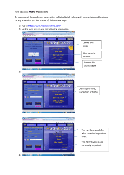

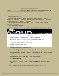

© Copyright 2026