
Workshop manual A Group 21-26, 30 D1-13, D1-20, D1-30, D2-40
Workshop manual
Group 21-26, 30
A
2(0)
D1-13, D1-20, D1-30, D2-40
Group 21–26, 30
Marine diesel engines
D1-13 A, D1-20 A, D1-30 A, D2-40 A
Contents
Safety information ............................................................
General information .........................................................
About this Workshop Manual .........................................
Spare parts .....................................................................
Certified engines ............................................................
Repair instructions ..........................................................
Our common responsibility ............................................
Torque ............................................................................
Torque-angle tightening .................................................
Lock nuts ........................................................................
Strength classes .............................................................
Sealant ...........................................................................
Safety rules for fluorocarbon rubber .................................
3
6
6
6
6
7
7
7
8
8
8
8
9
Special tools ................................................................... 10
Design and function
Group 21 Short block
Engine, general ............................................................ 12
Engine block ................................................................ 16
Cylinder head ............................................................... 16
Crankshaft .................................................................... 17
Timing gear .................................................................. 18
Crankcase breather ..................................................... 18
Group 22 Lubrication system
Lubrication oil system .................................................. 19
Oil valves ...................................................................... 20
Oil pump ....................................................................... 20
Oil filter ......................................................................... 20
Group 23 Fuel system
Fuel system .................................................................. 21
Injection pump .............................................................. 22
Centrifugal regulator .................................................... 22
Injectors ........................................................................ 22
Fuel filter ....................................................................... 23
Feed pump ................................................................... 23
Group 26 Cooling system
Cooling system ............................................................ 24
Thermostat ................................................................... 25
Heat exchanger ............................................................ 25
Sea water pump ........................................................... 25
Coolant pump ............................................................... 25
Group 30 Electrical system
Electrical system .......................................................... 26
Alternator ...................................................................... 27
Starter motor ................................................................. 27
Distribution box ............................................................ 27
Electrical components .................................................. 28
Repair instructions
When working with chemicals, fuel and lubricating oil 29
Before working in a boat .............................................. 29
Before lifting the engine ............................................... 29
Condition test, engine .................................................. 30
Compression test ......................................................... 30
Actions after lifting the engine ...................................... 30
Cooling system, draining ............................................. 31
Engine oil, draining/changing ...................................... 31
Engine fixture, fixing ..................................................... 32
Group 21 Short block
Short block, disassembly ............................................. 33
Inspection, component change, overhaul and
assembly of the short block engine ..................... 37-53
Inspecting the engine block ......................................... 37
Inspecting the cylinder head ........................................ 38
Changing the valve seats ............................................ 38
Grinding of valve and valve seats ................................ 39
Checking the valve guides .......................................... 40
Renovating the rocker arm mechanism ....................... 41
Inspecting the crankshaft ............................................. 42
Inspection of the and crankshaft bushing and
crankshaft journal ......................................................... 42
Inspection of main and big end bearings. ................... 42
Checking the big end bearing clearance: ................... 43
Piston ring inspection and fits ...................................... 44
Inspection and measurement of piston and cylinder
bore. ............................................................................. 44
Inspecting the con rod .................................................. 45
Changing the gudgeon pin bushing ............................ 45
Assembling the piston, piston rings and con rod. ........ 46
Camshafts and valve lifters, inspection ....................... 47
Measuring the camshaft ............................................... 47
Installing the crankshaft ............................................... 49
Installing the piston in the cylinder and the oil pan ..... 50
Installing the timing gear and injection pump .............. 51
Flank clearance, checking ........................................... 52
Measuring the piston height, installing the cylinder
head and other assembly ............................................ 53
Continued on next page
1
Table of contents
Cylinder head, removal ................................................ 56
Valves, removing .......................................................... 58
Valves, installation ....................................................... 58
Cylinder head, installation ........................................... 59
Timing gear, removing ................................................. 61
Timing gear, installation ............................................... 64
Pistons, removal ........................................................... 67
Big end bearing, change ............................................. 68
Pistons, change ............................................................ 68
Pistons, installation ...................................................... 69
Crankshaft, remove ...................................................... 70
Main bearings, change ................................................ 71
Crankshaft, assembly ................................................... 73
Flywheel, change ......................................................... 74
Crankcase seal rear, change ....................................... 75
Crankshaft seal, front, change ..................................... 76
Valves, adjustment ....................................................... 77
Drive belt, change ........................................................ 79
Group 22 Lubrication system
Oil pump bearing, changing ........................................ 80
Group 23 Fuel system
Injection pump, changing ............................................. 81
Injectors, changing ....................................................... 83
Injectors, testing ........................................................... 85
Injectors, check ............................................................ 85
Setting the engine speed ............................................. 86
Feed pump, changing .................................................. 87
Hand pump, changing ................................................. 88
Fuel system, venting .................................................... 89
Group 26 Cooling system
Coolant ......................................................................... 90
Pressure valve in filler cap, checking .......................... 91
Fault causes, cooling system ....................................... 91
Thermostat, change ..................................................... 92
Heat exchanger, cleaning ............................................ 93
Heat exchanger/exhaust manifold, changing .............. 94
Seawater pump, impeller change ................................ 95
Sea water pump, change ............................................. 96
Coolant pump, change ................................................ 97
Group 30 Electrical system
Alternator, changing ..................................................... 98
Starter motor, changing ................................................ 99
Wiring diagram ............................................................. 100
Technical data .............................................................. 103
References to Service Bulletins ................................. 116
© 2006 AB VOLVO PENTA
We reserve the right to make modifications without prior notice. Printed on environmentally compatible paper
2
Safety information
Introduction
This workshop manual contains technical data, descriptions and repair instructions for the Volvo Penta
products or product versions noted in the table of contents. Check that you have the correct Workshop
Manual for your engine.
Read the available safety information, “General information” and “Repair instructions” in the workshop
manual before you start to do any service work.
If work is done adjacent to a running engine, a
careless movement or a dropped tool can lead
to personal injury in the worst case.
Take care to avoid contact with hot surfaces
(exhaust pipes, Turbocharger, air intake pipe,
starter heater etc.) and hot fluids in pipes and
hoses in an engine which is running or has just
been stopped. Reinstall all protective parts removed during service work before starting the
engine.
Check that the warning or information labels on
the product are always clearly visible. Replace
labels which have been damaged or painted
over.
Important
In this book and on the product you will find the following special warning symbols.
WARNING! Warns for the risk of personal injury,
major damage to product or property, or serious
malfunctions if the instruction is ignored.
IMPORTANT! Is used to call attention to things
which could cause damage or malfunctions to
product or property.
NOTE! Is used to call attention to important information, to facilitate work processes or operation.
Below is a summary of the risks involved and safety
precautions you should always observe or carry out
when operating or servicing the engine.
Make it impossible to start the engine by cutting
system current with the main switch(es)and lock
it (them) in the off position before starting service work. Set up a warning notice by the helm
station.
As a general rule all service operations must be
carried out with the engine stopped. Some
tasks, such as adjustments, need the engine to
be running, however. Approaching an engine
which is operating is a safety hazard. Remember that loose clothing or long hair can fasten in
rotating parts and cause serious personal injury.
Never start the engine without installing the air
cleaner filter. The rotating compressor turbine in
the turbocharger can cause severe injury. Foreign objects entering the intake ducts can also
cause mechanical damage.
Never use start spray or similar products as a
starting aid. They may cause an explosion in
the inlet manifold. Danger of personal injury.
Avoid opening the coolant filling cap when the
engine is hot. Steam or hot coolant can spray
out and the system pressure will be lost. Open
the filler cap slowly, and release the pressure in
the cooling system if the filling cap or tap has to
be opened, or if a plug or coolant hose has to be
removed when the engine is hot. Steam or hot
coolant might spray out in an unexpected direction.
Hot oil can cause burns. Avoid skin contact with
hot oil. Ensure that the lubrication system is not
under pressure before carrying out any work.
Never start or operate the engine with the oil filler cap removed, otherwise oil could be ejected.
Stop the engine and close the sea cocks before
doing any work on the cooling system.
Only start the engine in a well- ventilated area.
When operated in a confined space, exhaust
fumes and crankcase gases must be ventilated
from the engine bay or workshop area.
Always use protective glasses or goggles when
carrying out work where there is a risk of splinters, grinding sparks, acid splashes or where
other chemicals are used. Your eyes are extremely sensitive, injury could cause blindness!
3
Safety information
Avoid getting oil on your skin! Repeated exposure to oil or exposure over a long period can result in the skin becoming dry. Irritation, dryness
and eczema and other skin problems can then
occur. Used oil is more dangerous than fresh oil
from a health aspect. Use protective gloves and
avoid oil soaked clothes and rags. Wash regularly, especially before eating. There are special
skin creams which counteract drying out of the
skin and make it easier to clean off dirt after
work is completed.
Most chemicals intended for the product (e.g.
engine and transmission oils, glycol, petrol (gasoline) and diesel oil) or chemicals for workshop
use (e.g. degreasers, paints and solvents) are
hazardous. Read the instructions on the product
packaging with care! Always follow the safety
precautions for the product (for example use of
protective mask, glasses, gloves etc.). Make
sure that other personnel are not inadvertently
exposed to hazardous chemicals, for example in
the air. Ensure good ventilation in the work
place. Follow the instructions provided when disposing of used or leftover chemicals.
Exercise extreme care when leak detecting on
the fuel system and testing the fuel injector nozzles. Use eye protection. The jet which comes
from a fuel injector has very high pressure and
considerable penetrationability. Fuel can force
its way deep into body tissue and cause severe
injury. Danger of blood poisoning (septicemia).
All fuels, and many chemicals, are flammable.
Do not allow naked flame or sparks in the vicinity. Petrol (gasoline), some thinners and hydrogen gas from batteries are extremely flammable
and explosive when mixed with air in the correct
ratio. No smoking! Ensure that the work area is
well ventilated and take the necessary safety
precautions before starting welding or grinding
work. Always ensure that there are fire extinguishers at hand when work is being carried out.
Make sure that oil and fuel soaked rags, and
used fuel and oil filters are stored in a safe
place. Rags soaked in oil can spontaneously ignite under certain circumstances. Used fuel and
oil filters are polluting waste and must be handed to an approved waste management facility
for destruction, together with used lubrication oil,
contaminated fuel, paint residue, solvents, degreasers and wash residue.
4
Batteries must never be exposed to open
flames or electric sparks. Never smoke close to
the batteries. The batteries generate hydrogen
gas when charged, which forms an explosive
gas when mixed with air. This gas is easily ignited and highly volatile. A spark, which can be
caused by incorrect battery connection, can
cause a single spark which is sufficient to
cause an explosion with resulting damage. Do
not move the connections when you attempt to
start the engine (risk of arcing), and do not
stand and lean over one of the batteries.
Always ensure that the Plus (positive) and Minus (negative) battery cables are correctly installed on the corresponding terminal posts on
the batteries. Incorrect installation can result in
serious damage to the electrical equipment. Refer to the wiring diagram.
Always use protective goggles when charging
and handling the batteries. Battery electrolyte
contains sulfuric acid which is highly corrosive.
Should the battery electrolyte come into contact
with unprotected skin wash off immediately using plenty of water and soap. If you get battery
acid in your eyes, flush at once with a generous
amount of water, and get medical assistance at
once.
Turn the engine off and turn off the power at the
main switch(es) before carrying out work on the
electrical system.
Clutch adjustments must be carried out with the
engine stopped.
The existing lugs on the engine/reversing gear
should be used for lifting the assembly.
Always check that the lifting devices are in good
condition and that they have the correct capacity for the lift (the weight of the engine plus the
reversing gear and extra equipment).
The engine should be lifted with a customized or
adjustable lifting boom for safe handling and to
avoid damaging components on top of the engine. All chains or cables should be parallel to
each other and should be as square as possible
to the top of the engine.
If other equipment connected to the engine has
altered its center of gravity, special lifting devices may be needed to obtain the correct balance
and safe handling.
Never do any work on an engine which just
hangs from a lifting device.
Safety information
Never work alone when removing heavy engine
components, even when using lifting devices
such as locking tackle lifts. When using a lifting
device two people are usually required to do the
work, one to take care of the lifting device and
another to ensure that components are lifted
clear and not damaged during the lifting operations.
When you work aboard a boat, always make
sure that there is enough space for disassembly
where you are working, with no risk of personal
injury or material damage.
Remember the following when washing with a
power washer: Never aim the water jet at seals,
rubber hoses or electrical components. Never
use a power washer for engine cleaning.
Only use the fuels recommended by Volvo Penta. Refer to the Instruction Book. Use of fuels
that are of a lower quality can damage the engine. On a diesel engine, poor quality fuel can
cause the control rod to bind and the engine to
overrev with resulting risk of damage to the engine and personal injury. Poor fuel can also lead
to higher maintenance costs.
Components in the electrical and fuel systems
on Volvo Penta products have been designed to
minimize the risks of explosion and fire. The engine must not be run in areas where there are
explosive materials.
5
General information
About this Workshop Manual
Certified engines
This workshop manual contains technical data, descriptions and repair instructions for the following marine diesel engines: D1-13, D1-20, D1-30 and D2-40.
When doing service and repair on emission certified engines, it is important to be aware of the following:
The engine designation and number are noted on the
number plate and engine decal. The engine designation and number must always be given in all correspondence about any product.
Certification means that an engine type has been
checked and approved by the relevant authority. The
engine manufacturer guarantees that all engines made
of the same type are equivalent to the certified engine.
The Workshop Manual is produced primarily for the
use of Volvo Penta workshops and service technicians. This assumes that people who use the Manual
have basic knowledge of marine drive systems and
can do the tasks of a mechanical or electrical nature
associated with the trade.
Volvo Penta constantly improves its products, so we
reserve the right to make modifications without prior
notification. All information in this manual is based on
product data which was available up to the date on
which the manual was printed. Any material changes
introduced into the product or service methods after
this date are notified by means of Service Bulletins.
This makes special demands on service and repair
work, as follows:
●
Maintenance and service intervals recommended
by Volvo Penta must be complied with.
●
Only Volvo Penta original spares may be used.
●
Service to injection pumps, pump settings and injectors must always be done by an authorized
Volvo Penta workshop.
●
The engine must not be converted or modified,
except for the accessories and service kits which
Volvo Penta has approved for the engine.
●
No installation changes to the exhaust pipe and
engine air inlet ducts may be done.
●
No seals on the engine may be broken by unauthorized persons.
The general advice in the instruction book about operation, care and maintenance applies.
Spare parts
Spare parts for electrical- and fuel systems are subject to various national safety requirements, such as
U.S. Coast Guard Safety Regulations. Volvo Penta
Original Spare Parts meet these specifications. Any
damage, occasioned by use of non-original Volvo
Penta spares for the product, will be not be compensated by the warranty offered by Volvo Penta.
6
IMPORTANT! Delayed or inferior care/maintenance, and the use of non-original spares, parts
means that AB Volvo Penta can no longer be responsible for guaranteeing that the engine complies with the certified version.
Damage and/or costs which arise from this will
not be compensated by Volvo Penta.
Repair instructions
The working methods described in the Workshop Manual apply to work carried out in a workshop. For this
reason, the engine is lifted out of the boat and mounted on an engine support. Unless otherwise stated, reconditioning work which can be carried out with the
engine in place follows the same working method.
The warning signs which occur in the workshop manual (please refer to “Safety information” for their meanings)
WARNING!
IMPORTANT!
NOTE!
are not comprehensive in any way, since we can not
of course foresee everything, because service work is
done in highly varying circumstances. For this reason,
all we can do is to point out the risks which we believe
could occur due to incorrect work in a well-equipped
workshop, using work methods and tools tested by
us.
All operations described in the Workshop Manual for
which there are Volvo Penta Special Tools available
assume that these tools are used when carrying out
the repair. Volvo Penta Special Tools have been specifically developed to ensure the most safe and rational working methods possible. It is therefore the responsibility of anyone using other tools or other working methods than we recommend to determine that
there is no risk of personal injury or mechanical damage or malfunction as a result.
In some cases special safety precautions and user instructions may be required in order to use the tools
and chemicals mentioned in the Workshop Manual.
These rules must always be observed, so there are no
special instructions about this in the workshop manual.
By following these basic recommendations and usingusing common sense it is possible to avoid most of
the risks involved in the work. A clean workplace and
a clean engine will eliminate many risks of personal
injury and engine malfunction.
Above all, when work on fuel systems, lubrication
systems, induction systems, turbocharger, bearing
caps and seals is done, it is extremely important that
no dirt or other kinds of foreign particles are able to
get in, since this would otherwise cause malfunctions
or shortened repair life.
Our common responsibility
Each engine consists of many interacting systems
and components. The deviation of one component
from the technical specification can dramatically increase the environmental impact caused by an otherwise good engine. For this reason, it is important that
the specified wear tolerances are observed, that systems which are adjustable are correctly adjusted and
that Volvo Penta Original Spares are used for the engine. The stated service intervals in the Maintenance
Schedule must be observed.
Some systems, such as the components in the fuel
system, require special expertise and special testing
equipment for service and maintenance. For environmental reasons etc., some components are sealed at
the factory. It is only permissible to work on sealed
components if you are authorized to do such work.
Remember that most chemical products, incorrectly
used, damage the environment. Volvo Penta recommends the use of biodegradable degreasers whenever
engine components are de-greased, unless otherwise
specified in the workshop manual. When working
aboard a boat, be careful to ensure that oils, wash
residue etc. are processed for destruction, and are not
inadvertently discharged with bilge water into the environment.
Torque
The tightening torque for vital fasteners, which should
be tightened with a torque wrench, are listed in “Technical Data: Special tightening torques” and noted in
the job descriptions in the book. All torque specifications apply to clean screws, screw heads and mating
faces. Torque data stated apply to lightly oiled or dry
threads. If lubricants, locking fluids or sealants are
needed on a fastener, the type of preparation to be
used will be noted in the job description. For fasteners
where specific torque values are not given, please refer to “Technical data, General Tightening Torque”.
7
Repair instructions
Torque-angle tightening
In torque/angle tightening, the fastener is tightened to the specified
torque, and tightening then continues through a pre-determined angle.
Example; for 90° angle tightening,
the fastener is tightened a further
1/4 turn in one sequence, after the
specified tightening torque has been
achieved.
Lock nuts
Disassembled locknuts shall not be re-used, they
shall be replaced by new ones, since the locking properties are impaired or lost when the nut is used several times. On locknuts with plastic inserts, such as Nylock® , the tightening torque specified in the table
must be reduced if the Nylock® nut has the same nut
height as a standard fully metallic hexagonal nut. Reduce the torque by 25% for screw size 8 mm or larger.
On Nylock® nuts with higher nut height, where the fully
metallic thread is as high as on a standard hexagonal
nut, use the tightening torques in the table.
Sealant
The sealants and locking fluids noted below shall be
used on the engines covered by this manual.
To ensure service work is correctly carried out it is important that the correct sealant and locking fluid type
is used on the joint where the agents are required.
In this Volvo Penta Workshop Manual the user will
find that each section where these agents are applied
in production states which type was used on the engine.
When sealants and locking fluids are used, it is important that the surfaces are free from oil, grease, paint
and rust-protection, and that they are dry. Always follow the manufacturer’s instructions use regarding temperature range, curing time and any other instructions
for the product,
Two different basic types of agent are used on the engine. These are:
RTV preparations (Room Temperature Vulcanizing).
Used for gaskets, sealing gasket joints or coating
gaskets. RTV is visible when a part has been disassembled; old RTV must be removed before resealing
the joint.
The following RTV preparations are used on the engine:
Volvo Penta sealant (cartridge 0.31 l, part. no.
1161231-4, or tube 20 g., part. no. 1161277-7) and
part. no. 840879-1 (tube 25 g).
Remove old sealant with denatured alcohol.
Anaerobic agents. These agents cure in the absence
of air. These preparations are used when two solid
components, such as two cast components, are fitted
together without a gasket. Common uses are also to
lock and seal plugs, stud threads, taps, oil pressure
monitors etc.
Strength classes
Screws and nuts are sub-divided into different
strength classes. The classification is shown by a
marking on the screw head. Markings of a higher number indicate stronger material. For example, a screw
marked 10-9 is stronger than one marked 8-8. For this
reason, it is important when fasteners are dismantled,
that the screws are put back in the correct places
when they are re-installed. If a screw must be replaced check in the spare parts catalogue to make
sure the correct screw is used.
8
Hardened anaerobic preparations are glassy and for
this reason, the preparations are colored to make
them visible.
Hardened anaerobic preparations are highly resistant
to solvents, and old compound must be removed mechanically. On re-assembly, it is important to degrease components carefully first, wipe off and apply
new sealant in accordance with the instructions.
The following anaerobic preparations are used on the
engines:
Volvo Penta thread locking fluid (part. no. 1161053-2)
and sealing compound (part. no. 1161059-9).
Repair instructions
Safety rules for
fluorocarbon rubber
Fluorocarbon rubber is a common material in seal
rings for shafts, and in O-rings, for example.
When fluorocarbon rubber is exposed to high temperatures (above 300°C), hydrofluoric acid can be
formed, which is highly corrosive. Contact with the
skin can result in severe chemical burns. Splashes in
your eyes can result in severe chemical burns. If you
breathe in the fumes, your lungs can be permanently
damaged.
WARNING! Observe the greatest care in working on engines which might have been exposed
to high temperatures, such as overheating during flame cutting or a fire. Seals must never be
cut with a flame torch during disassembly, or
burned in uncontrolled circumstances afterwards.
●
Always use chloroprene rubber gloves (gloves for
chemicals handling) and goggles.
●
Handle the removed seal in the same way as corrosive acid. All residue, including ash, can be
highly corrosive. Never use compressed air to
blow anything clean.
●
Put the remains in a plastic container, seal it and
apply a warning label. Wash the gloves under running water before removing them.
The following seals are most probably made from fluorocarbon rubber:
Seal rings for the crankshaft, camshaft, drive shafts.
O-rings, regardless of where they are installed. Orings for cylinder liner sealing are almost always made
of fluorocarbon rubber.
Please note that seals which have not been exposed to high temperature can be handled normally.
NOTE! As the illustrations in the service literature refer to
several engine variants, certain details may differ from any
particular engine. The essential information in the illustrations is always correct, however.
9
Special tools
856 927
885 484
885 252
885 023
885 498
885 820
885 510
885 822
998 9876
981 2519
885 824
998 6485
856 927
Measurement putty, for measuring main and big end
bearing clearance.
885 023
Valve spring compressor
885 252
Adapter for testing compression pressure
885 484
Adapter for testing compression pressure
885 498
Pressure foot, for valve compressor
885 510
Protective caps, fuel system
885 820
Puller, for pulley
885 822
Magnetic pen
885 824
Engine fixture
981 2519
Multimeter
998 6485
Equipment stand
998 8539
Compression tester
998 9876
Dial gauge
10
998 8539
Special tools
9995192
9995919
999 2520
999 9179
999 6662
999 9696
999 9683
999 9737
384 9639
999 9772
384 9640
999 2520
Equipment stand
999 5192
Holder, dial gauge, piston height measurement
9995919
999 6662
Puller, seals
Pressure testing device
999 9179
Spanner for removing fuel/oil filters
999 9684
Dial gauge
999 9696
Magnetic stand
999 9737
Fixture cylinder, for fixture 885 824
999 9772
Injector tester
384 9639
Installation tool for oil pump shaft (D1-13, D1-20)
384 9640
Installation tool for oil pump shaft (D1-30, D2-40)
11
Design and function
Group 21 Short block
Engine, general
The D1-13, D1-20, D1-30 and D2-40 are four cycle
marine diesel propulsion engines. They all have two
valves per cylinder, a high-mounted camshaft in the
engine block and a mechanical injection pump.
The D1-13 is an in-line two cylinder engine with a total
swept volume of 0.51 liter. The D-20 and D1-30 are inline three cylinder engines with total swept volumes of
0.76 and 1.13 liter respectively. The D2-40 is an inline four cylinder engine with a total swept volume of
1.51 liter.
The D1-13 and D1-20 engines have identical pistons
with the same dimensions. The D1-30 and D2-40 engines have different pistons, but of common dimensions.
D1-30 engine
12
The engines are lubricated by a pressure lubrication
system, in which an oil pump supplies oil under pressure to all lubrication points.
Fresh water cooling uses a thermostatically controlled
sea-water cooled heat exchanger. The sea water
pump is operated by a gear train.
The crankshaft operates the coolant pump and alternator via a drive belt.
Group: 21 Short block
Design and function
D1-13 A with MS10A reversing gear
D1-20 A with MS10A reversing gear
13
Design and function
Group: 21 Short block
D1-30 A with MS15A reversing gear
D2-40 A with 130S sailboat drive
14
Group: 21 Short block
Design and function
Location of information decals and type plates
There are type plates on the engine and transmission, marked with identification numbers. This information must
always be used a reference when spare parts are ordered. The appearance and location of the type plates is
shown below. The figures in brackets refer to the location of the identification number on the type plate.
Engine
Product designation (1) .......................................................................................................
Serial number (2) .................................................................................................................
Product number (3) .............................................................................................................
Certification number (4) .......................................................................................................
S - drive/Reversing gear
Product designation (5) ........................................................................................................
Serial number (6) ..................................................................................................................
Product number (7) ..............................................................................................................
Gear ratio (8) ........................................................................................................................
Propeller designation ............................................................................................................
Engine and transmission decal
D1-30, D2-40
D1-13, D1-20
XXXXXX (7)
XXX (5)
XX (8)
XXXXXXXXXX (6)
S - drive and reversing gear sign
Engine plate
15
Design and function
Group: 21 Short block
Engine block
The engine block is cast in one piece, from specially
alloyed cast iron. The camshaft is located in the engine block.
The D1-13 has two cylinder bores, the D1-20 and
D1-30 have three and the D2-40 has four.
The D1-13 and D1-20 have the same dimension per
cylinder. The D1-30 and D2-40 have a larger, common
dimension per cylinder.
None of the engines have cylinder liners. The cylinder
walls are machined directly in the engine block.
Sump
The sump is located under the engine block and is
made from pressed sheet metal. There is an oil drain
pipe under the sump.
Camshaft
The camshaft has lobes which operate the valves, the
fuel pump and the injection pump. The camshaft is
driven by the crankshaft and gear wheels, via the oil
pump gear wheel.
Cylinder head
The cylinder head (1) is made from specially alloyed
cast iron.
3
The cylinder head has one inlet and one exhaust valve
per cylinder. These are operated by the camshaft via
valve lifters and push rods. The valves have replaceable seats.
An injector is installed in the combustion chamber of
each cylinder. There is one glowplug per cylinder.
Rocker arm cover
The rocker arm cover (2) is made of aluminum and is
located above the cylinder head. The valve mechanism is installed underneath the cover. Pressurized
lube oil passes via an external pipe to the rocker arm
shaft, and then lubricates the rocker arms and valves.
2
Valve cover
The valve cover (3) is made of aluminum and is located above the rocker arm cover. The valve cover has
two internal sections, of which one leads inlet air down
into the cylinder head via an inlet. The other section
contains the crankcase ventilation valve.
1
16
Group: 21 Short block
Design and function
Crankshaft
10
The crankshaft (1) is supported by main bearings (2).
The thrust bearing is integrated in the rear main bearing cap (3). The crankshaft is statically and dynamically balanced, and has induction hardened bearing
surfaces. At the front end, where the gear wheel (4) for
the timing gear and the pulley (5) for the alternator and
coolant pump are located, the crankshaft has a groove
for a Woodruff key. At the rear of the crankshaft, there
is a flange (6) to which the flywheel is attached.
9
2
6
8
Main and big end bearings
The main and big end bearings (7) consist of steelshells lined with bearing metal. The bearings are precision made and are ready to be installed.
1
Con rods
The con rods (8) have an I-section. The small end is
drilled for gudgeon pin lubrication.
7
3
Pistons
The pistons (9) are made of light metal alloy. They
have three piston rings (10). Two piston rings are compression rings and one is an oil scraper ring.
4
5
17
Design and function
Group: 21 Short block
Timing gear
2
1
6
The timing gear consists of cylindrical gear wheels
with helical teeth, located at the front of the engine
block. A timing gear cover (1) provides complete protection for the timing gear.
The camshaft (2) and sea water pump (3) are driven
by the crankshaft gear (4), via an idler wheel (5). The
engine’s lubrication pump is integral with the idler
gear, and is driven by it. The regulator weights (6) are
hung at the front of the camshaft drive and adjust the
injection pump via a mechanism in the timing gear
cover.
4
5
3
Crankcase breather
The crankcase ventilation is sealed and pressure controlled with a valve and spring located in the valve
cover. When the gas pressure is higher, the valve
opens and directs the crankcase gases into the inlet
section, for combustion in the cylinders.
18
Group: 22 Lubrication system
Design and function
Group 22 Lubrication system
Lubrication oil system
The engines are provided with a complete pressure lubrication system. The lube oil pump is a gear wheel
pump, and is driven by the crankshaft. The lube oil is
lead through an external pipe to the valve mechanism.
The lube oil system has a reduction valve which limits
the maximum oil pressure in the engine.
The oil filter is a full-flow filter, with bypass valve.
8
7
1
1.
2.
3.
4.
5.
6.
7.
8.
Oil filter
Oil pressure monitor
Pressure reduction valve
Inlet pipe with strainer
Main oil duct
Oil pump
Oil supply pipe (outer) to valve mechanism
Crankcase ventilation, valve
2
6
3
4
5
19
Design and function
Group: 22 Lubrication system
Oil valves
1
The lubrication pressure is limited by a reduction
valve (1). The valve is installed in the lubrication system, just upstream of the oil filter (2). The valve opens
at high pressure and allows the oil to flow back into
the sump.
The D1-13 and D1-20 engines have a reduction valve
which opens in the interval from 352-448 kPa. On the
D1-30 and D2-40 engines, the valve opens in the interval from 304-500 kPa.
2
A bypass valve located on the oil filter opens if the resistance in the filter rises abnormally high. Oil supply
to the lubrication points is ensured in this way, even if
the filter is blocked, but the oil is no longer cleaned.
Oil pump
The lube oil pump is located in the idler wheel in the
timing gear, which also drives it.
The pump is a rotor pump, with an inner rotor and an
outer rotor, eccentrically mounted in relation to each
other. The inner rotor has one “tooth” less than the
outer rotor.
7
The function of the pump is that the volume of the
spaces between the inner and outer gears increases
and reduces. During the first section of the rotation of
the inner rotor, the volume increases, a partial vacuum occurs and oil is sucked into the inlet. After about
a half rotation, the volume is reduced and a pressure
occurs, which forces the oil out through the outlet.
6
5
8
1. Circlip
2. Spring washer
3. Spring
4. Shim
5. Cap for oil pump
6. Inner rotor
7. Idler wheel with outer rotor
8. Thrust washer
4
3
2
1
Oil filter
1
The purpose of the oil filter is to remove contamination from the oil. The filter is a full flow filter, which
means that all the oil is filtered before it is forced out
into the lubrication system.
Filter insert is a folded paper filter.
There is a bypass valve (1) at the base of the filter,
which opens and allows oil to flow past the filter if the
filter insert should become blocked.
When the filter has been in use for a pre-determined
time, it must be replaced by a completely new filter.
20
Group: 23 Fuel system
Design and function
Group 23 Fuel system
Fuel system
A mechanical feed pump sucks the fuel up from the
fuel tank, possibly through a water separation filter
(optional equipment), and the fuel is then forced
through the secondary filter to the injection pump.
The injection pump, which is driven by the camshaft,
then distributes fuel of specific quantity and timing to
the injectors.
Fuel which returns from the injectors is returned to the
base of the fuel tank. The air in the fuel system can
be transported back to the fuel tank via a connection
between the injection pump and the return fuel pipe.
The fuel is then forced through the injector nozzles
into a pre-combustion chamber in the cylinder head at
high pressure and then enters the combustion chambers in the pistons, where high speed air rotation contributes to even combustion. A glowplug in the precombustion chamber pre-heats the fuel mixture for
cold starting.
The secondary filter in the engine removes contamination which might be left in the fuel, despite the primary
filter.
5
7
6
4
1.
2.
3.
4.
5.
6.
7.
Fuel tank
Pre - filter
Feed pump
Fuel filter
Hand pump
Injection pump
Injectors
1
3
2
21
Design and function
Group: 23 Fuel system
Injection pump
The injection pump is a flange-mounted in-line pump
which is located on the engine block. The pump is
driven by cams on the engine’s camshaft, which operates the pump chambers directly.
The injection pump has the same number of pump
pistons as the engine has cylinders.
Centrifugal regulator
The regulator is mechanical, and uses regulatorweights for engine speed sensing. It is mounted on
the front of the camshaft gear, which also drives it.
The regulator weights operate the injector pump control rod via the regulation sleeve, a lever and a regulator arm. Engine speed is regulated across the engine’s entire speed range, from low idle to high idle (all
speed type).
Injectors
8
9
7
2
3 4
5
6
1
1.
2.
3.
4.
5.
22
Injector nut
Injectors
Joining piece
Compression screw
Spring
6.
7.
8.
9.
Adjustment washers
Injector holder
Washer
Nut
The engines is provided with pintle - type injectors.
Each injector basically consists of a nozzle retainer
and a nozzle.
When the fuel pressure increases to the set value
(opening pressure), the injector needle which is held
pressed against its seat by the compression spring is
lifted and atomized fuel is injected into the precombustion chamber of the engine.
The injector opening pressure is determined by the
compression spring tension, which is adjusted by adjustment washers.
Group: 23 Fuel system
Design and function
Feed pump
The feed pump is mounted on the outside of the engine block and is driven by an eccentric on the rear of
the camshaft.
3
4
2
Fuel filter
The fuel filter (1) is of the disposable type. The filter
insert is a paper filter.
The fuel filter is located in a bracket (2) together with
a hand pump (3) and vent screw (4).
1
23
Design and function
Group: 26 Cooling system
Group 26 Cooling system
General
The engine is fresh water cooled and has a sealed
cooling system with expansion tank. The system is
subdivided into two circuits.
In the inner circuit, the fresh watersystem, the coolant
is circulated by a coolant pump which is driven via a
belt from the crankshaft pulley.
The fresh water circuit operates under a certain
amount of excess pressure, which reduces the risk of
boiling if the temperature rises too high. If the pressure becomes higher than normal, a pressure valve
opens in the filler cap on the expansion tank.
7
The coolant temperature is regulated by a thermostat.
When the engine is cold, a thermostat directs the
coolant round an internal circuit in the engine. When
operating temperature begins to be reached, the coolant is progressively directed out through the entire
heat exchanger, where the surplus heat is removed.
In the outer circuit, the sea water system, sea water
is forced through by a gear-wheel driven pump with
rubber impeller.
The sea water system cools the engine’s heat exchanger. The sea water is returned together with the
exhaust gas, via a connection in the exhaust bend.
9
6
10
5
3
2
1
1.
2.
3.
4.
5.
6.
7.
8.
9.
10.
24
Sea water, inlet
Sea water filter
Sea water pump
Seawater, outlet
Coolant pump
Expansion tank
Heat exchanger/exhaust manifold
Thermostat
Open thermostat - circulation
Closed thermostat - circulation
8
4
Group: 26 Cooling system
Design and function
Thermostat
The engine is equipped with a thermostat whose sensor body contains wax.
When the engine is cold, the thermostat keeps the
path to the heatexchanger closed. Coolant then passes through a by-pass pipe, back directly to the suction
side of the pump. As the engine warms up, the volume of the wax increases and the thermostat progressively opens the passage to the heat exchanger, at
the same time as the by - pass channel is closed.
Please refer to the “Technical Data” chapter for opening temperatures.
The thermostat is located in a housing which is integrated in the heat exchanger and exhaust manifold.
Coolant pump
The coolant pump is mounted on the engine block and
is driven by the crankshaft by means of a drive belt.
Sea water pump
The sea water pump is a rubber impeller type pump,
and is mounted on the front of the engine. The pump
is driven from the engine’s timing gear system and
forces cooling water out to the heat exchanger on the
engine.
The impeller (pump wheel) is made of rubber, and is
replaceable.
NOTE! The impeller will be damaged if the pump is
run dry.
Heat exchanger
The heat exchanger is located in a housing which is
integrated with the exhaust manifold and thermostat.
Sea water passes through the heat exchanger matrix
and transfers heat from the internal cooling circuit in
the engine (fresh water system) to the outer circuit
(sea water). When the thermostat has not yet opened,
the coolant is lead through a short, uncooled passage
in the heat exchanger and back to the engine.
25
Design and function
Group: 30 Electrical system
Group 30 Electrical system
General
The engines have an alternator which supplies electric
current of 115 A. System voltage is 12 V and the
electrical system is single-pole.
The electrical system contains sensors for monitoring
the engine coolant temperature and oil pressure. A
distribution box contains a circuit breaker, and there
are two relays under the heat exchanger.
6
4
2
5
3
1
7, 8, 9
13
1.
2.
3.
4.
5.
6.
7.
8.
9.
10.
11.
12.
13.
26
Glow plugs
Stop solenoid
Coolant temperature monitor
Coolant temperature sensor
Distribution box
Circuit breaker
Starter relay
Glowplug relay
Charge sensing resistor
Starter motor
Alternator
Oil pressure monitor
Engine speed sensor
12
11
10
Group: 30 Electrical system
Design and function
Alternator
The alternator provides alternating current (14V/115A).
The voltage regulator on the alternator is provided with
a sensor system.
The sensor system compares the charge voltage between the alternator terminals, B+ and B-, with the
voltage across the battery positive and negative terminals. The voltage regulator then compensates for any
voltage drop in the cables between the alternator and
the batteries, by increasing the charge voltage supplied by the alternator as necessary.
When delivered from Volvo Penta, the sensor system
is not activated. The connection has probably been
done during engine installation, however.
Starter motor
The starter motor is a DC series motor. The starter
pinion is operated by a control solenoid and can be
slid axially on the rotorshaft.
The starter motor has a reduction gear, which makes
it possible to obtain greater torque.
The starter motor power depends on the engine it is
fitted to, please refer to the table below.
D1-13, D1-20
D1-30
D2-40
0.8 kW
1.1 kW
1.4 kW
Distribution box
Circuit breaker
A 16 A circuit breaker protects the electrical system
and cuts the current if overloaded.
If it has tripped, the electrical system is re-connected
by pressing the button on the circuit breaker in the
distribution box. Always first investigate the reason for
the overload.
Relays
The starting and glowplug functions are each controlled by a switching relay. These relays are identical
and are thus mutually interchangeable. They are located in the distribution box.
Charge sensing resistor
The charge sensing resistor has a value of 33 Ohm/
9 W.
27
Design and function
Group: 30 Electrical system
Electrical components
Lube oil pressure monitor - alarm
Contact type: Normally open. The contacts close if
the lube oil pressure in the engine falls below 0.5
±0.15 bar.
The closing pressure should be checked with falling
pressure.
Coolant temperature monitor - alarm
Contact type: Normally open. The contacts close if
the coolant temperature exceeds:
D1-13, D1-20
D1-30, D2-40
105oC ± 2oC
110oC ± 2oC
The switching point should be checked with rising
temperature.
Coolant temperature sensor
Resistance testing, measured with the sensor immersed down to the hex head screw for three minutes
in circulating fluid, with system current connected.
Temp. 60oC: 134.0 ±13.5 Ω (±4oC)
90oC: 51.2 ±4.3 Ω
(±4oC)
100oC: 38.5 ±3.0 Ω
(±4oC)
Engine speed sensor
The sensor is located on the flywheel housing and
uses inductance to give engine speed information
which changes with the speed of the engine.
Stop solenoid
The stop solenoid is an electrical stopping device
which shuts off fuel supply at the injection pump.
Glow plugs
One glowplug per cylinder is installed in the cylinder
head. All glowplugs are electrically connected by a
busbar.
The glowplugs heat the fuel mixture during starting.
28
Repair instructions
Group 21 Short block
General
A condition test should be done before each major
service activity, if possible, to determine the general
condition of the engine and discovery any concurrent
fault causes. A condition test requires the engine to
be run, so this should be done before the engine or
any engine components are disassembled.
Please refer to “Condition test, engine”.
When working with chemicals,
fuel and lubricating oil
IMPORTANT! Always use protective gloves for
work which includes contact with oil, fuel etc.
Constant skin contact with engine oil can be
very harmful.
Before lifting the engine
Boat removed from the water
1
Turn the battery isolator off, undo the battery connections on the starter motor.
2
Remove the connector for the engine cables to
the instruments.
3
Remove the sea water connections/cool keeling
connection.
4
Remove the exhaust pipe.
5
Close the fuel taps. Remove the fuel connections.
6
Remove the throttle and gear shift cables.
7
Undo the propeller shaft from the reversing gear.
Undo the engine mounting pads from the bed and
lift the engine out. Use the lifting lugs (1) on the
engine.
Before working in a boat
1 Turn the main switch off.
2 Clean the outside of the engine.
NOTE! Make sure that wash residue is collected
for destruction and does not inadvertently end up
in the water. Also refer to the warning text under
“Actions after lifting the engine”.
3 The work includes the following actions on the
cooling system: Close the sea cocks and drain
the coolant from the sea water and fresh water
systems.
WARNING! Make sure that all sea water inlets
are securely closed, so that water can not find
its way in during disassembly of cooling system
sub-components.
29
Repair instructions
Group: 21 Short block
Actions after lifting the engine
1 Clean the engine.
IMPORTANT! Remember the following when
washing with a power washer: Be extremely
careful when cleaning, to avoid getting water inside engine components. When a power washer
is used, the water jet must never be aimed at
seals, such as shaft seals, joints with gaskets,
rubber hoses or electrical components.
2 Drain the engine oil.
3 Remove the reversing gear (as necessary).
Flat Rate: 21035
Condition test, engine
Compression test
Special tools: 885 252, 885 484, 998 8539
A compression test is done, which shows the sealing
of the cylinders and valves, to assess the condition of
the engine in a simple, reliable manner.
•
Warm the engine up, then stop it.
•
Remove all the injectors and test each of the cylinders in turn.
IMPORTANT! Observe the greatest possible
cleanliness, to avoid getting dirt in the fuel system. Plug the connections for the disassembled
injectors and fuel pipes.
The compression pressure must be read at normal
starter motor speed.
Low combustion pressure in all cylinders indicates
worn cylinder bores and piston rings. If one cylinder
has lower compression pressure than the others, the
reason can be poor valve sealing, broken piston rings
or a damaged cylinder head gasket.
Insert adapter nos. 885 484 and 885 252 in the injector hole.
Install a compression gauge 998 8539 in the adapter,
and carry out the compression test.
30
Group: 21 Short block
Repair instructions
Cooling system, draining
D1-13 A
NOTE! Remove the expansion tank filler cap and
close the hull fitting before draining the cooling system.
F
WARNING! Open the pressure cap very carefully if the engine is hot. Steam or hot coolant can
spray out and cause burns.
1
Connect drain hoses to the taps on the fresh water
system. Open all drain points.
F
The sea water system is drained by undoing hoses at
the lowest points of the system.
2
Check that all water drains out.
F = Fresh water drain tap
Check whether the installation has any further taps or
plugs at the lowest points of the cooling water pipes
and exhaust pipe.
3
Close the taps.
4
Pump the bilges out as necessary. Check that no
leakage occurs.
Engine oil, draining/changing
Hot engine
1
Connect the suction pipe on the oil drain pump to the
oil drain pipe.
Suck the oil into a suitable vessel. The oil can also be
drained after the sump drain plug has been removed.
31
Repair instructions
Group: 21 Short block
Engine fixture, fixing
Drained cooling system and engine oil. Engine removed. Right front engine mounting removed.
Special tools: 885 224, 999 9737
Use fixture 885 224 and 999 9737 to fix the engine to
engine stand 998 6485. Only fixture 885 224 is needed
for fixing to engine stand 999 2520.
D1-13-A
D1-20-A
D1-30-A
D2-40-A
32
Screw the fixture to the right side of the engine, as in
the illustrations.
Group: 21 Short block
Repair instructions
Short block, disassembly
Empty the oil and water out of the engine. Lift the engine with a suitable lifting device. Installing the engine
fixture, please refer to “Engine fixture, fixing”.
WARNING! Observe the greatest possible
cleanliness in work on the fuel system. Watch
out for fuel spillage, diesel oil is hazardous on
repeated skin contact.
IMPORTANT! Observe the greatest possible
cleanliness, to avoid getting dirt in the fuel system. Plug the unions in the fuel system with
suitable protective plugs, such as kit no.
885510.
1
3
15
2
5
1.
Remove the induction silencer (1).
2.
Undo the expansion tank (2) and its bracket. Remove all coolant hoses (3) with brackets.
3.
Remove the electronic box (4) complete with cable harness. Undo the engine speed sensor (5).
NOTE! Note the way that the cable harness is
clamped before removing it.
16
14
4.
Remove the alternator (6) with bracket, starter
motor (7) and the left-hand engine mounting (8).
5.
Remove the heat exchanger/exhaust manifold (9),
sea water pump (10), coolant pump (11) with
spacer (D1-13).
6.
Remove the oil pressure monitor (12), dipstick
(13) and oil pressure pipe (14) from the cylinder
head.
7.
Remove the fuel filter bracket (15) with anchorage, feed pump (16) and feed hose by the union
(17) for the injection pump. Leave the fuel hoses
between the fuel filter, feed pump and union in
place.
17
13
12
D1-30-A 10
9
11
4
D1-13-A
8
6
7
33
Repair instructions
Group: 21 Short block
20
18
8.
Remove the fuel supply pipes (18) between the
fuel pump and injector, use the nut underneath the
fuel return pipe to avoid kinking the pipe. Remove
the fuel supply pipes and put them on a clean, dry
surface.
9.
Remove the return fuel pipe (19) and injectors
(20).
10. Unscrew the stop solenoid (21). Remove the injection pump (22). Remove the fixing screws and
nuts on the pump. Turn the stop lever clockwise
and carefully lift the pump, to make the lock clip
on the regulator arm accessible.
19
22
25
Remove the lock clip (23) and free the regulator
arm (24).
IMPORTANT! Be careful when disassembling
the injection pump, avoid damaging or bending
its lever.
21
NOTE! Save the shim/gasket (25) beneath the injection pump flange. Use the same thickness of shims
when re-installing, unless the camshaft, engine block
or injection pump has been changed.
23
24
26
11. Remove the valve cover (26), bus bar (27) and
glow plugs (28).
27
28
34
Group: 21 Short block
Repair instructions
12. Remove the lower part of the valve cover (29) with
the integrated rocker arm bridge. Start by unscrewing the two screws (30) on the edge, then
undo the rocker arm bridge nuts (31) one turn at a
time until the load on them has been relieved.
13. Prepare a stand, marked with cylinder numbers. If
the valve caps, push rods and valve lifters are to
be re-used, they must be put back in their original
places.
Lift the push rods and valve caps out and put in
them in number sequence in the marked stand.
32
31
29
40
30
17. Undo the screws (32) in the opposite sequence to
when they are tightened, please refer to “Technical Data”. Remove the cylinder head.
18. Remove the valve lifters out of the engine block
with a magnetic pen, part no. 885 822. If the valve
lifters are to be re-used, they must be put back in
their original places.
NOTE! The D1-20 and D2-40 engines have some
valve lifters which are chamfered off.
39
19. Remove the flywheel cover (33) and flexible coupling (34).
23. Undo the center nut (35) on the pulley. Remove
pulley (36), use special tool 885 820. Use the flywheel as a counterhold. Remove the Woodruff
key from the crankshaft.
33
34
37
38
36
35
20. Remove the flywheel (37).
22. Remove the inner flywheel housing (38) and rear
crankshaft seal.
40
35
Repair instructions
Group: 21 Short block
23. Remove the timing gear cover (39). Load the stop
arm (40) so that the springs on the inside of the
housing do not come out of position or spring out.
42
24. Remove the idler wheel (41) circlip. Save the
sleeve washer, spring and shims.
Lift away the idler wheel, complete with cover and
oil pump. Also remove the thrust washer behind
the idler wheel.
43
41
25. Remove the locking plate (42) screws. The
screws are accessible behind the holes in the
camshaft gear.
44
Lift out the camshaft (43), complete with gear and
regulator weights.
NOTE! Be careful to avoid damaging the bearings,
bearing tracks and camshaft lobes.
26. Remove the timing gear plate (44) with gasket.
48
45
48
46
47
27. Turn the engine over and remove the sump, together with the external oilpipe. Remove the oil
strainer (45) and oil suction pipe (46). Remove the
oil pressure reduction valve.
28. Scrape away the line of carbon at the top of the
cylinders, to facilitate removal.
Remove the big end bearing caps (47) and press
the pistons out.
NOTE! Check the markings on the big end bearing
caps.
29. Remove the locking screws (48) which hold the
main bearing caps. Lift the crankshaft out carefully, complete with caps, backwards.
NOTE! Tape the crankshaft gear to protect the bearing surfaces in the block during disassembly.
36
Group: 21 Short block
Repair instructions
Short block, inspection,
component change, overhaul
and assembly
Inspecting the engine block
Upper block plane
Check that the upper engine block plane does not
have any cracks or other damage. Also check that it
is not warped (in the same way as for the cylinder
head).
Max warpage, please refer to the “Technical Data”.
Change the engine block if it is outside the tolerances.
Flat Rate: 21302
Cylinder bore
Check that the cylinder bores are not scored or damaged in other ways.
Measure the cylinder bores at the upper and lower
turning positions for the piston rings (app 10 mm and
100 mm below the engine block plane) and also in the
middle. Measurement should be done with an internal
dial gauge and both along and transverse to the engine block (A and B).
For maximum permissible cylinder diameters, please
refer to “Wear tolerances” in Technical data.
37
Repair instructions
C
Group: 21 Short block
A
D
Inspecting the cylinder head
Cylinder head warping must not exceed the value given in “Technical data”. The check should be done with
a feeler gauge and a straight edge. Measurement is
done at six positions (A - F).
If warpage above the permissible level is found, the
cylinder head must be changed. If leakage has been
found, or if the cylinder head has blow lines, no special measurement is needed since such a cylinder
head will have to be attended to in any case.
Check the valve seats and check that the studs are
firmly seated.
F
B
A
E
Inspect the cylinder head for cracks. Carefully check
the areas around the valve seats and the holes for the
injector nozzles.
Changing the valve seats
The valve seats should be changed when distance
“A”, measured with a new valve exceeds 1.8 mm.
1.
Remove the old valve seat by heating it with a
gas torch (600 - 700oC), diagonally across the
seat.
Let the cylinder heat cool for 3 - 5 min in the air.
Then carefully tap the seat out with a mandrel
(check that the cylinder head is not damaged).
The valve seat can also be milled out (check that
the cylinder head is not damaged).
38
2.
Carefully clean the valve seat bed in the cylinder
head. Check the cylinder head for cracks.
3.
Cool the new valve seat with carbon dioxide snow
etc. to minus 60-70oC and possibly heat the cylinder head to 60-100oC.
4.
Seat the seat into the cylinder head. Use a hydraulic press and a suitable mandrel.
5.
Machine the seats to the correct angle and width.
Group: 21 Short block
Repair instructions
Flat Rate: 21401
Grinding of valve and valve seats
1.
Check valve stem wear. Measure the diameter
with a micrometer at points I, II and III.
Diameter, min. inlet: 6.89 mm
Diameter, min. exhaust: 6.84 mm
2.
Grind the valves in a valve grinding machine.
Grind the sealing surface as little as possible, but
just enough to “clean” it up. If the valve disc edge
(A) after grinding is less than 0.5 mm, scrap the
valve. Equally, any valve with a bent valve stem
must be scrapped.
B
A
3.
Check valve guide wear (please refer to “Checking
valveguides”) before the valve seats are machined.
4.
Mill the valve guides. When machined, only remove enough material to give the valve seat the
correct shape and a good mating surface.
Note. Do not grind so much that the valve depth exceeds the permissible value. Please refer to “Changing the valve seats”.
Mill new seats down so far that the distance between the cylinder head plane and the valve disc
surface (C) is 0.65 - 0.95 mm for the inlet and
0.85-1.15 mm for the exhaust.
The mating face (C) must be 45 degrees and the
contact surface (D) must be 1.70-2.10 mm.
C
D
5.
Grind the valves in with grinding paste, and check
contact with marker dye.
39
Repair instructions
Group: 21 Short block
Checking the valve guides*
Special tools: 999 9683, 999 9696
1
Put the cylinder head on the bench, and put
valves in the valve guides.
2
Measure the wear with a dial gauge 999 9683 and
magnetic stand 999 9696.
Lift each valve about 2 mm from its seat, put the
measurement tip on the edge of the valve heat
and check the wear.
Permissible clearance between valve and valve
guide:
Inlet valve, max clearance 0.20 mm.
Exhaust valve, max clearance 0.25 mm.
* Note. Since the valve guides are machined directly in the cylinder head, the cylinder head must be changed when the clearance is too great, even when the valve is new.
40
Group: 21 Short block
Repair instructions
Flat Rate: 21407
Renovating the rocker arm
mechanism
1.
Remove the plug at the front of the rocker arm
shaft. If the shaft has a stop screw, it must be removed before the shaft is pulled out.
2.
Disassemble the rocker arm mechanism. Remove
the rockerarms, springs and washers.
3.
Clean the components. Be specially careful with
the rocker arm oil ducts and the oil holes in the
rocker arms.
4.
Check the wear of the rocker arm shaft with a micrometer.
5.
Check whether the rocker arm bearing surfaces
have been worn oval. Check the clearance between rocker arm and shaft.
Check that the spherical section of the adjustment screw is not deformed or worn. The threads
on the pin and lock nut should be undamaged.
The lock nut should be in good condition.
6.
Oil the rocker arm shaft and disassemble the other components.
41
Repair instructions
Group: 21 Short block
Inspecting the crankshaft
Clean all the drillings in the crankshaft carefully after
disassembly and inspect it very carefully to find out
whether it really needs to be renovated.
1.
Check wear and ovality with a micrometer. Measure diameters “A - A” and “B - B” at points “1”
and “2”.
Max. permissible taper and ovality in the main
and big end bearings is 0.05 mm. Change the
crankshaft if these values are exceeded.
2.
Measure lengthwise crookedness in the crankshaft (runout). Put the crankshaft in a couple of Vblocks which are placed under the front and rear
main bearing journals. Alternately, the crankshaft
can be set up between centers. Measurements
shall be done on the center main bearing
journal(s).
Max lengthwise crookedness (runout), please refer to “Technical Data”.
If these values are exceeded, the crankshaft
must be changed.
3.
Check that the crankshaft seal mating surfaces
on the crankshaft are not worn or damaged.
Inspection of the and crankshaft
bushing and crankshaft journal
Check the bearing clearance between the crankshaft
journal and the crankshaft bushing. Use both internal
and external micrometers.
1.
Measure the inner diameter of the bushing at
points 1 and 2. Measure in two directions (”A” and
“B”) at each point.
2.
Measure the outer diameter of the bearing journal
and calculate the bearing clearance (difference
between the former measurement and the max.
diameter of the bearing journal).
Max bearing clearance, please refer to “Technical
Data”.
Change the bushing if the clearance exceeds the
permissible value.
Inspection of main and big end
bearings
Check the main and big end bearing shells, and the
front main bearing bushing. Change worn bearing
shells, or any with damaged bearing surfaces.
42
Group: 21 Short block
Repair instructions
Checking the big end bearing
clearance:
Special tools: 856927 (measurement putty)
The radial clearance of the big end bearings can be
checked by means of measurement putty part no.
856927 as follows:
1.
Wipe off any oil from the big end bearing and big
end journal. Apply a piece of measurement putty,
the same length as the width of the bearing journal, and put the putty along the big end bearing
journal. Avoid the oil hole.
2.
Install the con rod and bearing cap (note the
alignment marking) and tighten the con rod
screws.
Tightening torque, please refer to the “Technical
Data” chapter.
NOTE! Do not rotate the con rod or crankshaft during
measurement, since this spoils the measurement
strip.
3.
Remove the big end cap and measure the width of
the pressed-out measurement putty at the widest
point. Use the rule which is enclosed with the
measurement putty.
Max permissible big end bearing clearance,
please refer to the “Technical Data”.
Change the main bearing if the bearing clearance
exceeds the permissible value.
43
Repair instructions
Group: 21 Short block
Piston ring inspection and fits
1.
Remove the piston rings with piston ring pliers.
2.
Remove the gudgeon pin circlips and remove the
gudgeon pin carefully, with a suitable mandrel.
3.
Check that the rings do not bind in the piston ring
grooves.
4.
Check the piston ring gap. Slide the ring down below the bottom dead center position using a
piston. Change the piston ring if the gap exceeds
1.0 mm.
Check the piston ring gap with new rings. Please
refer to the “Technical Data, specifications” chapter for measurements.
In general, piston rings should be changed if there
is any noticeable wear or out - of - roundness in
the cylinders, since the piston rings frequently do
not end up in the same positions as they had before disassembly.
Oil consumption is also of decisive importance for
the point in time when a piston ring change should
be done.
5.
Check the clearance in the piston ring grooves.
Roll the ring in its groove in the piston, and measure the clearance at several points with a feeler
gauge. Please refer to the “Technical Data, specifications” chapter for measurements.
Inspection and measurement of
piston and cylinder bore
Check the pistons for cracks and worn piston ring
grooves. Change the piston if it has deep grooves in
the skirt surface. Likewise, if the piston has one or
more cracks in the gudgeon pin hole. If any such
damage is found, the injection equipment should also
be checked.
Measure the piston diameter with a micrometer, at
right angles to the gudgeon pin hole and 10 mm from
the lower edge of the piston. Then measure the
cylinder bore and calculate the clearance between cylinder and piston.
Change the piston if the clearance exceeds the maximum permissible value, or if the piston diameter is
less than the minimum permissible value.
44
Group: 21 Short block
Repair instructions
Inspecting the con rod
1.
Check the con rods for cracking, straightness and
twist before considering changing the gudgeon pin
bush.
Discard the connecting rod if it is cracked, bent or
twisted.
Check the wear in the “small end” with a gudgeon
pin. When the clearance is correct, an oiled gudgeon pin should slowly slide through the bush under its own weight.
2.
Use a new gudgeon pin and measure the straightness of the con rod, using a fixture. Max. deviation: 0.15 mm on 100 mm measured length
3.
Measure con rod twist. Max. deviation: 0.20 mm
on 100 mm measured length
4.
Check the end float between the con rod and
crankshaft. Change the con rod if the end float exceeds 0.035 - 0.085 mm.
Also check the gudgeon pin bushes. Please refer
to “Technical Data”, for the clearance between
gudgeon pin (A) and gudgeon pin bush (B).
Flat Rate: 21641
Changing the gudgeon pin
bushing
1.
Press the old bush out.
2.
Press the new bush in.
NOTE! Make sure that the oil hole in the bush lines up
with the drilling in the con rod. Draw a line across the
hole in the con rod and the bush, with a felt tip pen.
Check that the oil duct is open after pressing.
3.
Broach the bush and measure the con rod with an
internal dial gauge.
45
Repair instructions
Group: 21 Short block
Assembling the piston, piston
rings and con rod
1.
Install one of the circlips in the piston.
2.
Oil the gudgeon pin and gudgeon ring bush.
3.
Warm the piston to about 100oC. Place the piston
and con rod so that the markings line up.
The marking on the con rod and the “SHIBAURA”
marking inside the piston must face the same
way.
Slide the gudgeon pin in.
NOTE! It should be possible to slide the gudgeon pin
in easily. It must not be driven in.
A
1
4.
Install the other circlip.
5.
Check that the con rod does not move stiffly in
the gudgeon pin bush.
6.
Check the big end bearing clearances. Please refer to “Inspecting the crankshaft” and “Inspecting
the main and big end bearings”.
7.
Check the piston ring gap in the cylinder bores,
and check that the rings do not bind in the piston
ring grooves.
8.
Install the piston rings on the pistons, using piston ring pliers. Letters or markings on ring surfaces must always be turned so that the marking faces upwards.
Install the oil scraper ring first. Put the expansion
spring (1) for the oil scraper ring in the lower piston ring groove, with the location dowel (A) inside
both ends of the spring. Check that the ends of
the expansion spring do not overlap. Install the oil
scraper ring (2) above the expansion spring.
Check that the ring gap is installed with 180o displacement to the guide pin.
4
3
2
Install the ring with the tapered surface (3) in the
centre piston ring pair so that the marking faces
the piston crown.
Install the upper ring (4) with the marking upwards.
Check that the ring openings are at 90o to each
other.
46
Group: 21 Short block
Repair instructions
Camshafts and valve lifters,
inspection
1
Check with a steel rule (1), that the valve lifter mating
surfaces against the camshaft are convex or flat. If
the surface is concave, change the valve lifter.
If the valve lifter is worn all across the lifting surface,
the valve lifter should be scrapped. The “ditch” shows
that the valve lifter has not rotated.
A dark line on the outside of the valve lifter shows
that the surface is not worn, on the other hand. It is
the condition of the valve lifters which determines
whether it is necessary to check the camshaft wear.
Check that the lifting surfaces on the camshaft and
the valve lifters do not have large areas of pitting
damage. Pitting damage can occur for various reasons. The damage is caused when small pieces of
metal loosen from the hardened surface. Lifters and
camshafts with minor pitting damage can be used.
Pitting damage seldom become worse.
Check that the camshaft bearing surfaces and cam
curves are not abnormally worn. The cams could be
obliquely worn in an axial direction, for example.
Change the camshaft if major damage or wear occurs.
NOTE! When the camshaft is changed, all the valve
lifters must be changed.
Measuring the camshaft
Cam height (inlet and exhaust), “A” 26.5 mm
Cam height “B” (for injection pump) 41.8 mm
Cam height “C” (for injection pump) 27.0 mm
Change the camshaft if the wear limits have been exceeded.
47
Repair instructions
Group: 21 Short block
Guidelines for replacement
In normal conditions, un-evenness may occur on the
camshaft lobes in the engine. This does not mean
that the camshaft has to be changed. These marks do
not have any negative influence on either engine performance or durability of the engine and its components.
Examples are shown below, of acceptable and not acceptable wear.
Acceptable wear.
Not acceptable wear.
The camshaft does not need to be changed.
NOTE! The camshaft and associated rocker arms
must be changed.
48
Group: 21 Short block
Repair instructions
Installing the crankshaft
1.
Check the cleanliness of the crankshaft drillings
and bearing surfaces, engine block and bearing
caps. Check that the bearing shells and their beds
do not have any burrs or upsets.
2.
Put the main bearings in their places in the
bearing caps. Bearing shells with an oil hole must
be placed in the upper bearing cap. Check that
the lubrication holes in the upper bearing
shells are centered on the oil ducts.
3.
Oil the bearings and the main bearing journals and
install the bearingcaps in their places. The chamfered edges must face forwards on all bearing
caps. Please refer to the illustration, to identify
the location of the bearing caps.
4.
Torque the bearing caps, please refer to the
“Technical Data” chapter for tightening torque.
5.
Carefully lift the crankshaft into place in the engine block. Align the main bearing retainer screw
holes (1) before the crankshaft is pressed into
place.
Note. Tape the crankshaft gear before lifting the
crankshaft into place, to prevent the gear teeth
from damaging the front bearing seat.
6.
Torque the main bearing caps in the engine block.
Tightening torque, please refer to the “Technical
Data” chapter.
7.
Check that the end float does not exceed. 0.5 mm
by using a special tool, magnetic stand 999 9696
and dial gauge 998 9876.
49
Repair instructions
Group: 21 Short block
Installing the piston in the
cylinder and the oil pan
Note. After changing the crankshaft, piston or gudgeon pin, the weight difference between the con rod
complete with piston and piston rings must not exceed 10 g between each cylinder. Also refer to “Pistons, installing” and “Assembly of pistons, piston rings
and con rod”.
1.
Lubricate the pistons and piston rings with engine
oil beside the rings, so that the oil finds its way
into the piston ring grooves. Turn the piston rings
so that the piston ring gaps are aligned at a 90o
angle to each other.
Make sure that no piston ring gap is placed centrally against the gudgeon pin.
2.
Put the bearing shells in their places in the con
rods and caps. Oil the crankshaft journal with engine oil.
3.
Check that the markings on the piston crown or
inside the piston line up with those on the con rod.
Use a piston ring compressor (1) and install the
piston with con rod in its cylinder, starting with
cylinder no. 1 (forwards).
IMPORTANT! Make sure that the con rod studs
to not strike the crankshaft when driven down.
The con rod with the lowest number must be installed furthest forward (in cylinder no. 1) and accordingly, the con rod with the highest number
goes closest to the flywheel.
The con rod must be aligned with the marking
(number/paint dot) facing the injection pump (camshaft side).
4
3
2
4.
Install the bearing caps (2) and tighten the con rod
screws. Tightening torque, please refer to the
“Technical Data” chapter. Bearing caps must be
installed so that the number markings/paint marks
on con rod and cap coincide.
Undamaged con rod screws do not need to be
changed, they can be put back again.
5.
Install the oil suction pipe (3) and oil strainer (4).
Tightening torque, please refer to the “Technical
Data” chapter. Use a new O - ring.
IMPORTANT! Do not press the oil suction pipe
down to the bottom of the hole. There is a risk
that an oil duct could be blocked.
6.
50
Install the sump together with a new gasket.
Tightening torque, please refer to the “Technical
Data” chapter.
Group: 21 Short block
Repair instructions
Installing the timing gear and
injection pump
3
Also refer to “Timing gear, installation”.
2
1
1.
Install the timing gear plate (1) with new gasket.
2.
Oil the camshaft bearing surfaces and carefully
lift the camshaft (2) into place, complete with
drive gear and regulator weights.
Note. Be careful to avoid damaging the bearings,
bearing tracks and camshaft lobes.
4
3.
Install lock plate (3) for the camshaft in the correct position and torque it.
4.
Put the key in place in the crankshaft and install
the crankshaft pulley (4).
IMPORTANT! The components must be oiled before installation.
5
IMPORTANT! Make sure that the gear wheel
markings coincide.
6
5.
7
8
Install the thrust washer (5) on the idler wheel
shaft stub. Install the idler wheel (6) in accordance with the markings.
NOTE! Do not turn the crankshaft before the timing
gear cover has been installed.
9
12
6.
Install the inner rotor (7) and the oil pump cover
(8). Install shims (9), spring (10), spring washer
(11) and lock washer (12).
7.
Adjust the oil pump end float (13) to 0.10 - 0.15
mm. Shims (9) are available in thicknesses of
0.10; 0.15; 0.20 and 0.50 mm.
8.
Install a new, possibly adjusted gasket for the
timing gear cover. Center the cover in front of the
oil pump.
10
11
Note. Check that the tubular pin (14) in the timing cover can engage in the hole (15) in the oil pump cover.
Turn the cover back and forwards, and center it in the
mid position. The stop arm (16) must be turned and
held in place when the timing cover is installed.
9
13
9.
15
14
17 18
16
Check that the starter spring (17) is correctly located in the timing cover, and is connected to the
regulator arm (18).
Put the timing gear cover in place. Insert the
regulator arm through the hole in the engine block.
Screw the timing gear cover down.
7.
Turn the stop arm (19) clockwise and connect the
arm (20) to the injection pump. Install the clip
(21).
51
Repair instructions
Group: 21 Short block
NOTE! Be careful to ensure that the shim/gasket
which was placed underneath the injection pump
flange is put back, before the pump is placed in the
block (applies when the pump has been removed).
19
21
8.
Torque the injection pump, please refer to the
“Technical Data” chapter for tightening torque.
9.
Install a new front crankshaft seal, please refer to
“Front crankshaft seal, changing”. Put the key in
place in the crankshaft and install the crankshaft
pulley. Tightening torque, please refer to the
“Technical Data” chapter.
20
Flank clearance, checking
Use a feeler gauge to measure the flank clearance (1)
between the oil pump gear and the camshaft gear.
Use a feeler gauge to measure the flank clearance (2)
between the oil pump gear and the crankshaft gear.
Please refer to the “Technical Data” chapter for min
and max values.
52
Group: 21 Short block
Repair instructions
1
2
Measuring the piston height,
installing the cylinder head and
other assembly
Also refer to “Cylinder head, installation”.
1.
Clean the cylinder head and engine block mating
planes. Remove any rust from screw holes and
from the threads on the cylinder head screws.
2.
Put the valve lifters in their original places.
IMPORTANT! Please refer to “Timing gear, assembly”, for the positions of the valve lifters.
3.
Put the new cylinder head gasket in place with
the marking (1) upwards. Check that the tubular
pins (2) are installed in the block.
NOTE! The new gasket must be of the same thickness as the old one.
NOTE! If a piston, con rod, crankshaft or engine block
has been changed, new measurement must be done.
Difference in height
between pistons and
engine block plane
Gasket thickness
0.55 to 0.64 mm
1.2 mm
0.65 to 0.75 mm
1.3 mm
4.
3
4
5
Dip the cylinder head screws in engine oil and
leave them to run off on a strainer. The screws
should have stopped dripping when they are installed (otherwise oil cold well up and be regarded
as leakage).
IMPORTANT! The screws are phosphated and
must not be cleaned with a steel wire brush. If
the cylinder head is painted, the contact surfaces for the cylinder head screws must be free
from paint. The clamping force in the joint could
otherwise be very poor.
5.
Put the cylinder head in place.
6.
Torque the cylinder head screws (3) in three stages, where the last stage is to the stated torque.
Tightening schedule and torque, please refer to
“Technical Data”.
Re-tighten all screws.
7.
Install the glowplugs (4) and busbar (5).
53
Repair instructions
Group: 21 Short block
7
9
8
Install the push rods (6), valve caps (7) and rocker arm mechanism (8) with gasket. Torque the
nuts (9), please refer to “Technical Data”.
9.
Install the oil supply pipe (10) between the block
and the rocker arm mechanism, together with the
oil pressure monitor (11). Install the oil pressure
reduction valve (12). Tightening torque, please refer to “Technical Data”.
6
14
13
18
8.
17
Turn the crankshaft round a couple of rotations.
15
10. Adjust the valve clearance, please refer to
“Valves, adjustment”.
10
16
19
11. Install the valve cover (13). Check that the small
ventilation hole in the crankcase ventilation cover
(14) is open.
12. Install copper gaskets for the injectors.
Install the injectors (15). Torque please refer to
“Technical Data”.
11
13. Install the hollow screw (16) on the injection pump
and the banjo nipple with new copper washers.
12
D1-30-A
14. Install new copper gaskets and install the return
fuel pipe (17). Tighten the nuts and connect the
return pipe.
15. Install the fuel supply pipes (18), tightening
torque, please refer to “Technical Data”.
16. Install the coolant pump (19) with spacer (D1-13A) and a new gasket.
21
17. Install the rear crankshaft seal seat in the engine
block and the mating surface on the inner flywheel
housing. Install the rear crankshaft seal (20).
18. Apply an even layer of sealant (VP no. 840 879)
around the crankshaft seal and the camshaft cover (21).
20
54
Group: 21 Short block
38
Repair instructions
19. Install the inner flywheel housing (22). Install the
flywheel (23) as previously marked, please refer
to “Technical Data” for tightening torque. Then install the flexible coupling (24) and the flywheel
housing (25). Install the engine speed sensor (26)
on the flywheel housing.
29
28
26
20. Install the dipstick (27).
20. Install the fuel filter bracket (28) with anchorage
and feed pump (29). Please refer to “Technical
Data” for tightening torque.
Connect the fuel hoses and tighten the hose
clamps.
25
24
23
D1-30-A
22
40
35
27
39
21. Install the heat exchanger/exhaust manifold (30)
and sea water pump (31).
30
36
22. Install the starter motor (32) and alternator (33),
together with the front engine mounting (34).
23. Install the expansion tank with fixing yoke (35).
24. Connect all coolant hoses (36). Tighten all hose
clamps and brackets.
25. Install the electronic box (37) with cable harness,
connect the connectors and other electrical connections. Clamp the cable harness as previously
noted.
31
26. Install the induction silencer (38).
27. Remove the engine fixture and install the engine
mounting (39).
37
D1-13-A
34 33
32
28. Install a new oil filter (40). Add oil and coolant, as
specified in “Technical Data”.
29. Install the engine in the boat. Connect the remaining connections and controls to the engine. Open
the fuel taps and the sea cock. Start the engine
and check carefully that no leakage occurs.
55
Repair instructions
Group: 21 Short block
Cylinder head, removal
Coolant drained. Air filter housing, heat exchanger
and coolant pump with spacer (D1-13) removed.
1
Remove the screw (1) which holds the fuel filter bracket to the cylinder head.
Unscrew the valve cover.
Undo the cable (2) for the glow plugs.
2
Undo and remove the injector pipes (1). Undo and remove the return fuel pipe (2).
IMPORTANT! Seal all openings in the fuel system with protective caps.
3
Undo the oil supply pipe (1) by the cylinder head.
Unscrew the injectors (2).
IMPORTANT! Seal all openings on the injectors
with protective caps.
Unscrew the nuts (3) which hold the rocker arm
bridge. The D1-20, D1-30 and D2-40 engines also
have screws which must be undone. Carefully prise
the rocker arm bridge loose.
56
Group: 21 Short block
Repair instructions
4
Remove the push rods (1) and valve caps (2). Mark
them.
Undo the cylinder head screws (3) in the opposite sequence to when they are tightened, please refer to
“Technical Data”. Remove the cylinder head and gasket.
57
Repair instructions
Group: 21 Short block
Valves, removing
Cylinder head removed.
Special tools: 885023, 885498
1
Remove the busbar (1) and glow plugs (2).
Remove the valves (3) with a valve compressor, tool
nos. 885023 and 885498. Mark the valves.
Remove the valve seals.
Valves, installation
Special tools: 885023, 885498
1
Install the valve (1) in the cylinder head as marked.
Install a new valve seal (2), spring (3) and valve
spring washer (4).
Put the valve compressor in place. Compress the
valve spring and install the collets (5).
2
Install the glow plugs and tighten to the specified
torque, please refer to the “Technical Data” chapter.
Install the bus bar.
58
Group: 21 Short block
Repair instructions
Cylinder head, installation
Special tools: 998 9876, 999 5192
1
Check the piston height with tools 9989876 and
9995192. Select a new cylinder head gasket, please
refer to “Technical data”.
Check that the valve lifters are in place.
2
Check that the engine block guide pins for the cylinder
head are in place. Install a new cylinder head gasket
with the marking upwards.
Put the cylinder head in place. Insert the screws (1)
and torque them as in the tightening schedule, to the
torque specified in “Technical Data”.
3
Install the push rods (1) and valve caps (2).
59
Repair instructions
Group: 21 Short block
4
Install a new seal on the rocker arm bridge (1). Install
a new rocker arm bridge. Make sure that the push
rods and rocker arms (2) are correctly aligned.
Tighten the nuts (3) evenly to the specified torque,
please refer to the “Technical Data” chapter.
5
Install the oil supply pipe (1) on the cylinder head with
new seals.
6
Installing the injectors:
Apply sealant part. no. 840879 to the threads of the
two lowest screws (1).
Put new copper seals on the bottom of the cylinder
head.
Install the injectors and tighten them evenly to the
specified torque, please refer to the “Technical Data”
chapter.
60
Group: 21 Short block
Repair instructions
Timing gear, removing
Cylinder head removed
Special tools: 885820, 885 822
1
Unscrew the seawater pump (1). Remove the end panel (2) and the screws (3).
2
Unscrew the centre nut from the pulley. Install tool no.
885820 on the pulley and remove it.
Remove the Woodruff key from the groove in the shaft
3
Unscrew the injection pump (1). Lift it up until the lock
clip (2) is accessible. Undo the clip and release the
control rod (3).
61
Repair instructions
Group: 21 Short block
4
Unscrew the timing gear cover screws (1) and nut (2).
Remove the cover.
5
Undo the fuel pipe from the fuel filter (1).
Unscrew the fuel feed pump (2). Wipe up the fuel that
has run out.
6
Remove the valve lifters with magnetic tool 885822.
IMPORTANT! Mark the valve lifters so that they
are put back in the same positions. The D1-20
and D2-40 engines have some valve lifters
which are chamfered off.
62
Group: 21 Short block
Repair instructions
7
Rotate the camshaft until the socket cap screw (1) becomes visible in the hole in the camshaft drive gear.
Unscrew the socket cap screw and hex head screw
(2). Remove the lock plate (3).
Remove the camshaft regulator sleeve (4).
Pull the camshaft out carefully.
IMPORTANT! There is a risk that the inner camshaft bearing can be damaged by a camshaft
lobe if it is pulled out with force.
8
Remove the circlip (1) on the oil pump shaft. Remove
all components of the oil pump. Note the spacer
washer (2) inside the oil pump gear.
9
Unscrew the remaining screws (1). Remove the timing
gear plate (2).
Undo the crankshaft gear (3) with a puller. Remove
the gear wheel and its Woodruff key.
63
Repair instructions
Group: 21 Short block
Timing gear, installation
1
Put the gear wheel (1) and its key on the crankshaft.
Tap the gear wheel on.
Install a new gasket and timing gear plate (2).
Tighten the inner screws (3) on the timing gear plate.
2
Carefully insert the camshaft.
IMPORTANT! If you force the camshaft in,
there is a risk that one of the cam lobes will
damage an internal bearing.
Put the lock plate (1) in position. Rotate the camshaft
until the screw hole for the socket cap screw (2) becomes visible in the hole in the camshaft drive gear.
Screw the lock plate down.
Install the camshaft regulator sleeve (3).
3
Fit the thrust washing (1) in place.
Put the oil pump gear wheel (2) in place. Make sure
that the markings (3) on the gear wheel line up with
the markings (4) on the other gear wheels.
Check the gear flank clearance, please refer to “Gear
flank clearance, checking”.
64
Group: 21 Short block
Repair instructions
4
Install the pump gear (1), end washer (2), shims (3),
spring (4) and bush (5) in the oil pump gear. Put the
circlip (6) on the shaft.
NOTE! Note that the end washer (2) has a hole (7)
which must mate up with the guide pin in the timing
gear cover.
Install a new gasket on the timing cover.
NOTE! If the gasket has a center section (8), this
must be cut away.
5
Put the control rod (1) on the heel (2) in the timing
gear cover. Turn the stop arm (3) round so that the
control rod is held against the heel.
6
Install the timing gear cover at the same time as the
control rod (1) is held fixed by the stop arm (2).
Put the timing gear cover in place. Make sure that the
control rod ends up in the correct position and that the
pin (3) engages in the hole (4) in the oil pump end
washer.
Screw the timing gear cover down.
65
Repair instructions
Group: 21 Short block
7
Put a new O-ring (1) in the groove in the seawater
pump.
Install the rear end piece (2) with a new gasket and its
four screws (3).
NOTE! The longest screws must be put on the outside (D1-13, D1-20).
Install the seawater pump and screw it in place.
8
Install the pulley key on the crankshaft.
Install the pulley and tighten it to the specified torque
with the center nut, please refer to the “Technical
Data” chapter.
9
Put the valve lifters in place as marked.
IMPORTANT! All valve lifters must be put back
in their old places. Not that on engine D1-20,
valve lifter no. 2 for cylinder 1 has one chamfer
(1). On engine D2-40, both valve lifters for cylinder 1 have one chamfer.
D1-20 A
66
Group: 21 Short block
Repair instructions
Pistons, removal
Engine oil drained. Cylinder head removed.
1
Turn the engine upside down. Undo the oil drain pipe
anchorage (1) on the cylinder head.
Unscrew the sump (2) and remove it together with the
oil drain pipe (3).
2
Unscrew the oil suction strainer (1). Remove the suction pipe (2) with its O-ring.
Unscrew the bearing caps (3) for the con rods.
IMPORTANT! Note the markings on the bearing
caps and their locations.
3
Press the pistons out.
NOTE! There might be a soot deposit on the top of
the cylinder bores. Remove the deposit to make it
easier to press the pistons out.
67
Repair instructions
Group: 21 Short block
Big end bearing, change
Pistons, removed
1
Remove the big end bearings (1) and put the new
ones in position.
Flat Rate: 21320
Pistons, change
1
Note the positions of the pistons in relation to the
crankshaft.
Remove the circlips (1) and press the gudgeon pin out
(2).
2
Clean the gudgeon pin bushing and check it.
3
Install a new piston in the correct position.
Press the gudgeon pin in.
Install the circlips with the lugs facing upwards.
68
Group: 21 Short block
Repair instructions
Pistons, installation
1
Also refer to “Assembly of pistons, piston rings and
con rod”.
Install a piston ring compressor on the piston.
Lubricate the con rod bearing shells and studs with
engine oil.
2
Turn the crankshaft round so that the big end bearing
is in the lowest position for the piston to be installed.
Install the piston (1) in the bore and carefully tap it
down. The piston marking “ SHIBAURA” must face
the injection pump side.
IMPORTANT! Make sure that the con rod studs
to not strike the crankshaft when driven down.
3
Install the big end bearing cap as marked. Torque to
23 Nm (D1-13, D1-20 or 32 Nm (D1-30, D2-40).
Check the movement of the big end bearing.
Repeat the procedure to install the remaining pistons.
69
Repair instructions
Group: 21 Short block
Crankshaft, remove
Removed pistons, flywheel and timing gear
1
Unscrew the inner timing gear plate (1).
2
Remove the rear crankshaft seal (1) from the crankshaft.
3
Unscrew the oil pressure reduction valve.
4
Undo the screws (1) which hold the main bearing caps.
Lift the crankshaft out.
NOTE! Tape the crankshaft gear teeth to protect the
bearing when the shaft is pulled out.
70
Group: 21 Short block
Repair instructions
Main bearings, change
Crankshaft, removed
1
Unscrew the main bearing retainers (1) and pull them
off the crankshaft.
IMPORTANT! The marking (2) on all main bearing retainers for D1-20, D1-30 and D2-40 must
be carefully noted to prevent incorrect positioning during assembly. Also note the oil holes (3)
in the bearing caps.
D1-20, D1-30
D2-40
2
Drive out the main bearing bush (1) located in the engine block. Use a suitable mandrel and tap the bushing out from inside the crankcase.
3
Inspect all main bearings (1). Remove them from their
holders.
Check and measure the bearing surfaces (2) on the
crankshaft, please refer to “crankshaft inspection”.
71
Repair instructions
Group: 21 Short block
4
Install the new main bearings and lubricate them with
engine oil.
Install the main bearing retainers (1) on the crankshaft
in accordance with the markings (2). Torque the
screws to 23 Nm.
IMPORTANT! Put the main bearing retainers
back in their original places. The oil holes (3)
must face the corresponding holes in the engine
block.
5
Install the main bearing bush (1) in the engine block.
IMPORTANT! Position the bushing so that its
oil hole is correctly aligned in the engine block.
The oil groove (2) in the bushing must be furthest in.
Tap the bushing in with a suitable mandrel (3) until it
lines up with the engine block.
Check that the oil duct is open after pressing in. Also
check the internal diameter of the bushing. For dimensions, please refer to “Technical Data”.
72
Group: 21 Short block
Repair instructions
Crankshaft, assembly
1
Lift the crankshaft into place.
Align the main bearing retainer screw holes (1) before
the crankshaft is pressed into place.
2
Carefully tap the crankshaft into place if necessary,
and torque the main bearing retainers to 27 Nm.
Check that the crankshaft can be turned easily.
3
Install the oil pressure reduction valve with a new
seal. Torque to 64 Nm.
Install a rear crankshaft seal, please refer to “Rear
crankshaft seal, changing”.
73
Repair instructions
Group: 21 Short block
Flat Rate: 21661
Flywheel, change
1
Remove the engine speed sensor (1) and filter housing bracket (2).
Remove the flywheel cover (3) and flexible coupling.
2
Unscrew the flywheel (1) and remove it.
Clean and check the crankshaft seal.
3
Carefully clean the crankshaft and flywheel.
Install the new flywheel and tighten it to the specified
torque, please refer to the “Technical Data” chapter.
Install the flexible coupling, flywheel housing, filter
housing bracket and engine speed sensor.
74
Group: 21 Short block
Repair instructions
Crankcase seal rear, change
Flywheel removed
1
Unscrew the inner timing gear plate (1).
2
Remove the rear crankshaft seal (1).
Check that the area for the crankshaft seal on the engine block, the crankshaft and the inner flywheel
housing are cleaned.
Lubricate the lip of the seal on the new crankshaft
seal with engine oil and put the seal in place.
Apply sealant part no. 840879 all round the crankshaft
seal (2) and the camshaft cover (3).
Fix the inner flywheel plate.
75
Repair instructions
Group: 21 Short block
Flat Rate: 21672
Crankshaft seal, front, change
Special tools: 885820, 9995919
1
Undo the drive belt.
Unscrew the centre nut from the crankshaft pulley. Install tool no. 885820 on the pulley and remove it.
Remove the Woodruff key from the groove in the shaft
2
Insert tool no. 9995919 under the lip of the crankshaft
seal (1) and pull the seal out.
Clean the crankshaft and seal surfaces. Tape the key
groove on the crankshaft to avoid damaging the new
seal during assembly.
3
Lubricate the new crankshaft seal with engine oil and
put it on the crankshaft. Drive the seal into place with
a suitable mandrel.
Remove the tape.
4
Install the pulley key on the crankshaft.
Install the pulley and tighten it to the specified torque
with the center nut, please refer to the “Technical
Data” chapter.
Install and adjust the drive belt.
76
Group: 21 Short block
Repair instructions
Flat Rate: 21403
Valves, adjustment
Stationary, cold engine
1
Remove the air filter housing (1) and valve housing
(2).
2
D1-13
Crank the engine clockwise until the valves (1) for no.
1 cylinder shift position. Then crank the engine exactly one more turn. You can now adjust the valves for
no. 1 cylinder. Please refer to item 3 for the adjustment procedure.
Crank the engine until the valves (2) for no. 2 cylinder
shift position. Then crank the engine exactly one more
turn. Adjust the valves for no. 2 cylinder.
D1-20, D1-30
Crank the engine clockwise until the valves for no. 1
cylinder shift position. Adjust no. 2 inlet valve (1) and
no. 3 exhaust valve (2). Please refer to item 3 for the
adjustment procedure.
Crank the engine clockwise until the valves for no. 2
cylinder shift position. Adjust no. 3 inlet valve (3) and
no. 1 exhaust valve (4).
Crank the engine clockwise until the valves for no. 3
cylinder shift position. Adjust no. 1 inlet valve (5) and
no. 2 exhaust valve (6).
77
Repair instructions
Group: 21 Short block
D2-40
Crank the engine clockwise until the valves for no. 4
cylinder shift position. Adjust no. 1 inlet and exhaust
valve (A). Please refer to item 3 for the adjustment
procedure.
Crank the engine clockwise until the valves for no. 2
cylinder shift position. Adjust no. 3 inlet and exhaust
valve (B).
Crank the engine clockwise until the valves for no. 1
cylinder shift position. Adjust no. 4 inlet and exhaust
valve (C).
Crank the engine clockwise until the valves for no. 3
cylinder shift position. Adjust no. 2 inlet and exhaust
valve (D).
3
Adjustment
Undo the locknut (1) with a ring wrench. Measure the
valve clearance (2) with a feeler gauge. Adjust the
valve clearance with the adjustment screw (3).
The correct valve clearance for all valves and engines
is 0.2 mm.
When the correct valve clearance has been reached,
tighten the locknut (1).
4
Install the valve cover with a new seal.
Install the air filter housing.
Test run the engine and check that no oil leakage occurs.
78
Group: 21 Short block
Repair instructions
Flat Rate: 23641
Drive belt, change
1
Lightly loosen the lower fixing screws (1) on the alternator. Loosen the upper fixing nut (2).
Loosen the tension screw (3) and slacken the drive
belt. Remove the drive belt.
2
Install a new drive belt. Tension the belts with tensioner screw. Check the tension.
Tighten the alternator fixing nut and fixing screws.
IMPORTANT! D1-30, D2-40: Be careful to ensure that the alternator belt is placed in the
groove closest to the alternator.
D1-30, D2-40
79
Repair instructions
Group: 22 Lubrication system
Oil pump bearing, changing
Timing gear and crankshaft removed
Special tools: 384 9639 (D1-13, D1-20), 384 9640 (D130, D2-40)
1
Drive out the oil pump bearing section (1) located in
the engine block. Tap it out from inside the crankcase.
2
Use special tool 384 9639 for D1-13 and D1-20, 384
9640 for D1-30 and D2-40.
First screw the guide pin (1) for the tool into the engine block.
Then put the new oil pump bearing (2) into the tool
block (3).
NOTE! It is important that the engine block surface
touching the tool is clean and even. The tool block
must be oiled.
3
Place the tool block with the bearing in place, using
the guide pin.
Tap the bearing into place until the tool bottoms on
the cylinder head.
80
Group: 23 Fuel system
Repair instructions
Injection pump, changing
1
Unscrew the stop solenoid (1).
Undo the supply pipe (2) to the injection pump.
Undo the supply pipes (3) and return fuel pipe (4).
IMPORTANT! Seal all openings in the fuel system with protective caps.
2
Unscrew the injection pump (1). Lift it up until the lock
clip (2) is accessible. Undo the clip and release the
control rod (3).
Lift the injection pump out and remove the shim.
81
Repair instructions
Group: 23 Fuel system
3
Put a new shim of the same thickness on the pump
housing. Insert the new injection pump into the housing and fix the control rod with the lock clip.
Fix the oil supply pipe (1) on one of the studs (2).
Tighten the injection pump to the specified torque,
please refer to “Technical Data”.
Install the supply pipe (3).
5
Install the stop solenoid (1) with a new seal.
Install the fuel return pipe (2).
Install the fuel supply pipes (3) and tighten to the
specified torque, please refer to the “Technical Data”
chapter.
82
Group: 23 Fuel system
Repair instructions
Flat Rate: 23710
Injectors, changing
2
1
Clean round the injectors (1).
3
5
1
4
Undo the fuel supply pipes (2) by the injection pump
and the injectors. Lift the fuel supply pipes away together.
Remove the nut (3) at the top of each injector, use the
nut (4) underneath the fuel return pipe (5) to avoid
kinking the pipe. Lift the return fuel pipe away.
Unscrew the injectors. Remove the copper seals under the injectors.
IMPORTANT! Seal all openings in the fuel system with protective caps.
2
Install the new injectors with new copper seals. Apply
sealant, part no. 840 879 to the two lowest threads
(1). Tightening torque, please refer to the “Technical
Data” chapter.
Install the new return fuel pipe, use the nut underneath
the fuel return pipe to avoid kinking the pipe.
Install the fuel supply pipes. Check that they do not
come out of alignment, and tighten the nuts. Tightening torque, please refer to the ”Technical Data” chapter.
3
Start the engine and check that no leakage occurs.
83
Repair instructions
Group: 23 Fuel system
Flat Rate: 23701
Renovating the injectors
8
9
7
2
3 4
5
Injector nut
Injectors
Joining piece
Compression screw
Spring
Clean the outside of the injector.
2.
Fix the injector (holder) in a vise. Unscrew the injector nut and take the injector apart.
Note. Be careful that the injector nozzle does not fall
out during disassembly.
3.
6
1
1.
2.
3.
4.
5.
1.
6.
7.
8.
9.
Adjustment washers
Injector holder
Washer
Nut
Pull the injector nozzle out of the injector sleeve
and put the components in cleaning petrol (gasoline).
Note. Make sure that the injector needles and injector
sleeves which belong with each other, and fit together,
are not mixed up if several injectors are cleaned at the
same time. To avoid mixing up, the injectors should
be put in an injector stand or in different compartments.
4.
Check each injector carefully with an illuminated
magnifier or an injector microscope. Also check
the other components.
5.
When you install a new injector, it is important
that conservation oil is washed off the injector
needle and sleeve before the injector is assembled (avoid skin contact with the sliding surfaces
of the needle).
Clean the components in chemically pure petrol
(gasoline). Check that the injector needle slides in
the sleeve, with no tendency to binding.
84
6.
Dip the injector components in pure Diesel or testing oil, and fit the components together. Use the
original thickness of adjustment washer(s) to set
the opening pressure.
7.
Check the opening pressure, jet pattern and sealing in an injector tester.
Group: 23 Fuel system
Repair instructions
Injectors, testing
Testing is done in an injector tester. During the test,
the opening pressure and sealing are the most important things. The spray pattern is more difficult to assess, and does not give a reliable indication of the
injector’s status.
WARNING! Be careful when testing injectors,
avoid getting the fuel jet from an injector on unprotected parts of your body. The jet has such
powerful penetration ability that it can force its
way in under your skin and cause blood poisoning (septicemia).
Opening pressure
With the pressure gauge connected, press the injector
tester lever down slowly until the injector opens and
releases fuel. Read off the opening pressure at the
opening instant.
If the value read does not coincide with the specified
value, the setting must be changed. This is done with
washers.
Note. The opening pressure is increased or reduced
by about 1 MPa by a change in thickness of the
spacer by 0.1 mm.
Injectors, check
Spray pattern
1.
Pump the injector tester, special tool 9999 772,
and check the injector spray pattern. The fuel jet
should be conical and in line with the centerline of
the injector. Fuel drops must not occur in the jet.
2.
Check that the fuel jet has a circular cross section.
Sealing
When sealing is checked, investigate the fuel leakage
which can occur between the injector nozzle seat and
the tapered sealing surface in the injector sleeve.
1.
Wipe the injector nozzle tip dry.
2.
Pump the pressure up to about 2 MPa below the
opening pressure of the injector (please refer to
Technical Data). Keep the pressure constant for
about 10 sec. and check that no fuel drips out
from the tip of the injector. Damp injectors can be
approved.
Install protective caps on the injector pipe couplings
and over the injector nozzle tips, if the injectors will
not be used at once.
85
Repair instructions
Group: 23 Fuel system
Setting the engine speed
Check that the accelerator control functions normally,
i.e. the actuator arm (1) is pressed against the low idle
stop (2) when the accelerator control is at idle, and is
pressed against the full throttle screw (3) when the accelerator control is at full throttle. Adjust the control if
necessary. Also check that the air filter is not
blocked, and that the air inlet is not blocked.
IMPORTANT! The engine’s fuel volume and
speed are set at the factory to give highest power and least environmental impact. These settings must not be disturbed.
6
7
8
NOTE! Seals on injection equipment may only be broken by authorized personnel. Seals which have been
broken must be re-sealed.
Low idle
5 4 3
1.
2.
3.
4.
5.
7.
86
1
2
Actuator arm
Adjustment screw, low idle
Stop screw, full throttle
Adjustment screw, racing speed
Adjustment screw, max. fuel volume
Lock nut
1.
Check that the gap (6) is about 3 mm when the
accelerator is in the idle position. If necessary:
Undo lock nut (7) and adjust screw (8) to give the
correct gap.
2.
Warm the engine up and check the idling speed
with a tachometer (please refer to Technical data
for correct idling speed).
3.
Use adjustment screw (2) to adjust to give the
correct idling speed.
4.
Check the gap (3) again as in item 1.
Racing speed (high idle)
Warm the engine up and check the racing speed with
a workshop tachometer when the engine is unloaded
at full throttle (please refer to “Technical data” for correct racing speed).
Adjust the following as necessary
1.
Loosen the stop screw (3) so that it does not limit
the movement of the actuator arm (1).
2.
Run the engine without load at full throttle and adjust the racing speed to the correct value with adjustment screw (4). Remember to seal the screw
afterwards.
3.
Adjust stop screw (3) to give a clearance of 0.1
mm between stop screw (3) and the actuator arm
(1) when the throttle control is at the full throttle
position.
Group: 23 Fuel system
Repair instructions
Flat Rate: 23311
Feed pump, changing
1
Put a rag under the feed pump to collect spilled fuel.
Undo the unions (1) on the feed pump.
Unscrew the feed pump (2).
2
Put a new O-ring in the feed pump.
Install the feed pump and screw it in place.
Install the fuel unions on the feed pump.
87
Repair instructions
Group: 23 Fuel system
Flat Rate: 23341
Hand pump, changing
1
Put a rag under the filter housing bracket to collect
spilled fuel. Undo the secondary filter (1). This must
be sorted as environmentally hazardous waste.
Undo the fuel unions (2).
Unscrew the hand pump (3) and remove it.
2
Put a new secondary filter in the new hand pump.
Install the hand pump on the bracket.
Screw the fuel unions tight.
Vent the fuel system, please refer to “Fuel System,
Venting”.
88
Group: 23 Fuel system
Repair instructions
Flat Rate: 23080
Fuel system, venting
1
Open the vent screw (1) located above the fuel filter
bracket.
NOTE! Check whether the copper washer on the vent
screw needs to be changed.
2
Press the hand pump (2) located on the fuel filter
bracket until fuel with no air bubbles comes out of the
vent screw. Keep pumping at the same time as the
vent screw is closed.
Pump another 10 strokes.
3
Wipe up the fuel that has run out.
Start the engine and check sealing.
89
Repair instructions
Group: 26 Cooling system
Coolant
Mixing
WARNING! All glycol is hazardous and pollutes
the environment. Flammable. Do not swallow it!
Mix:
40% “Volvo Penta Coolant” (conc. coolant)
60% water
This mixture prevents against internal corrosion, cavitation and frost bursting down to about –28°C. (At
60% glycol concentration, the freezing point is lowered to –54°C.) Never mix more than 60% concentrate
(Volvo Penta Coolant) in the coolant. This will give reduced frost protection and poorer cooling effect, with a
consequent risk of overheating.
IMPORTANT! The coolant must be mixed with
pure water, use distilled – de-ionized water.
IMPORTANT! It is extremely important that the
correct concentration of coolant is put in the
system. Mix in a separate clean vessel before
filling the cooling system. Make sure that the
liquids mix.
Filling the coolant
Flush the cooling system clean before new coolant is
added.
Close all drain points and fill up with coolant to the
correct level.
The engine must be stationary when the cooling
system is filled, and must not be started until the
system is vented and completely filled. If a heating
unit is connected to the engine cooling system, the
heat control valve should be fully opened and the installation vented during filling.
Check all hoses and joints, and rectify any leaks.
Fill the system slowly! Filling must not be done so
fast that air locks are formed in the system. The air
should be allowed to flow out through the filling opening. Check the coolant level after the engine has been
run for about an hour. Top up with coolant as necessary.
Checking the coolant level
WARNING! Do not open the filler cap when the
engine is warm, except in emergencies. Steam
or hot fluid could spray out.
Turn the filler cap to the first stop and allow any excess pressure to hiss out before removing the cap
completely. Top the coolant up as necessary. The
level must be between the MAX and MIN markings.
90
Group: 26 Cooling system
Repair instructions
Pressure valve in filler cap,
checking
Special tools: 9996662
1. Drain some of the coolant and connect the pressure testing device to a nipple or other plugged
hole in the cooling system.
2.
Extend the drain hose from the filler pipe with a
hose which ends up in a water - filled vessel.
3.
Increase the pressure and read the pressure
gauge when the valve opens (water bubbles into
the vessel with the drain hose). The valve should
open at 0.075 MPa.
4.
Remove the test equipment. Install the plug and
fill the engine up with coolant.
Fault causes, cooling system
Too low coolant temperature
Low coolant temperature can be caused by:
•
Faulty thermostat.
•
Faulty temperature sensor or instrument.
•
Low engine loading.
Excessive coolant temperature
Excessive coolant temperature (warning lamp lights
up) can be caused by:
•
Blocked sea water inlet or sea water filter.
•
Defective impeller in the sea water pump.
•
Too low coolant level, air in the fresh water system.
•
Slipping or broken vee belt for the coolant pump.
•
Faulty thermostat, temperature sensor or instrument.
•
Blocked cooling system.
•
Incorrectly set injection advance in the injection
pump.
•
Filler cap gasket does not seal.
Coolant losses
There are two types of coolant losses:
•
Coolant losses during operation.
•
Coolant losses after stopping a hot engine.
Coolant losses during operation can be caused by
poor sealing in the cooling system, or that air or combustion gases are forced into the cooling system and
force coolant out through the pressure cap.
91
Repair instructions
Group: 26 Cooling system
Flat Rate: 26271
Thermostat, change
1
Drain the coolant.
Undo the thermostat housing (1). Remove the O-ring
from the cap.
Remove the thermostat (2) and seal.
2
Install a new thermostat and seal.
Install the thermostat housing cover with a new Oring. Tighten the screws to the specified torque,
please refer to “Technical Data”.
3
Fill up with coolant.
Warm up, and check the sealing and coolant level.
92
Group: 26 Cooling system
Repair instructions
Heat exchanger, cleaning
Drained cooling system and sea water. Air filter
housing removed. Expansion tank and bracket removed (D1-30 and D2-40)
1
Undo the heat exchanger end wall on the alternator
side.
Remove the exhaust pipe elbow (1) and hose clamp
(2) from the heat exchanger end wall. Remove the exhaust pipe elbow.
Undo the other end wall (3) from the heat exchanger.
2
Take the insert out (1) and scrap it.
3
Install new O-rings (1) on the insert end wall.
Slide the insert in from the alternator side. Screw the
end wall onto the heat exchanger.
4
Install new O-rings (2) on the insert and end wall.
Screw the end wall onto the heat exchanger.
Install the exhaust pipe bend.
5
Fill up with coolant. Check the fluid level and sealing
after warming up.
93
Repair instructions
Group: 26 Cooling system
Heat exchanger/exhaust
manifold, changing
Current cut off with the main switch. Drained cooling system and sea water. Expansion tank and
bracket removed (D1-30, D2-40).
1
Undo the hose union on the exhaust pipe elbow.
Unscrew the distribution box (1) and fold it to one
side.
2
Undo the hose connections (1).
Undo the screws (2) and carefully prise the heat exchanger/exhaust manifold away.
Remove the gasket.
3
Clean the sealing surfaces of the cylinder head.
Transfer the exhaust pipe elbow to the new heat exchanger/exhaust manifold.
Install the new heat exchanger/exhaust manifold and
gasket. Start to tighten the screws from the center
and then outwards. Torque to 10 Nm.
Install the distribution box on the exhaust manifold.
4
Install the hose unions and junction to the exhaust
pipe elbow.
Fill up with coolant.
Warm up, and check the sealing and coolant level.
94
Group: 26 Cooling system
Repair instructions
Flat Rate: 26652
Seawater pump, impeller
change
Close sea cock
1
Unscrew all screws on the cover (1).
2
Remove the impeller (1) with water pump pliers.
3
Clean the pump housing and sealing surfaces.
4
Grease the new impeller and housing. Put the impeller
and a new gasket in the housing.
Screw the cover down.
Open the sea cock and start the engine. Check the
sealing.
95
Repair instructions
Group: 26 Cooling system
Flat Rate: 26612
Sea water pump, change
Close sea cock
1
Undo the hose connections (1) for the seawater pump.
Undo the four screws (2) which hold the seawater
pump.
2
Remove the seawater pump and the O-ring.
Check the mating surfaces.
NOTE! Check the seawater pump gear wheel. If it is
damaged, the idler gear must be changed as well.
3
Install a new sea water pump and O-ring.
Install the screws and hose unions.
Open the sea cock and run the engine. Check the
sealing.
96
Group: 26 Cooling system
Repair instructions
Flat Rate: 26211
Coolant pump, change
1
Drain the coolant.
Undo the hose connections (1) for the coolant pump.
Loosen the tension (2) on the drive belt and remove it.
2
Undo the temperature sensor connector (1).
Loosen the screws (2) and nut (3) which hold the coolant pump and alternator stay (4).
Remove the coolant pump and alternator stay.
D1-13:
Also remove the spacer which is located between the
coolant pump and engine block.
3
Clean the sealing surfaces.
Transfer the temperature sensor, hose union and pulley to the new coolant pump.
4
Install the new coolant pump with new seals, spacer
(D1-13) and alternator stay.
Install and tension the drive belt.
Install the hose connections.
5
Fill up with coolant.
Warm up, and check the sealing and coolant level.
97
Repair instructions
Group: 30 Electrical system
Flat Rate: 32111
Alternator, changing
Current cut off with the main switch
1
Mark and undo all electric connections to the alternator.
2
Loosen the upper fixing nut (1).
Undo the tension screw (2) to release the upper fixing
screw (3) for the alternator.
Unscrew the lower fixing screw (4) and remove the alternator.
3
Put the new alternator in position and tighten the lower
fixing screw. Tighten it loosely.
Put the upper fixing screw in position and lightly tighten the upper fixing nut. Screw the tension screw into
the fixing screw.
Put the drive belt in place and tension it with the tension screw.
IMPORTANT! D1-30, D2-40: Be careful to ensure that the alternator belt is placed in the
groove closest to the alternator.
D1-30, D2-40
4
After checking the drive belt tension, tighten the lower
fixing screw and upper fixing nut.
Install the electric connections on the alternator.
98
Group: 30 Electrical system
Repair instructions
Flat Rate: 33111
Starter motor, changing
Current cut off with the main switch. Alternator removed (D1-13).
1
Undo all electric connections (1) to the start solenoid.
2
Undo the screws (2) which hold the starter motor.
Lift the starter motor out.
3
Put the new starter motor in position and fix it with the
screws.
Install the electric connections on the starter motor.
4
Switch the current on and check the starter motor
function.
99
Wiring diagram
Wiring diagram
Engine
1.
2.
3.
4.
5.
6.
7.
8.
9.
10.
11.
12.
13.
14.
Battery
Starter motor
Alternator
Main switch
Glow plugs
Oil pressure monitor
Stop solenoid
Coolant temperature monitor
Coolant temperature sensor
Circuit breaker, 16 A
Starter relay
Glow plug relay
Charge sensing resistor, 33 Ohm/9W
Engine speed sensor
Cable colors
BL
LBL
BN
LBN
GN
GR
=
=
=
=
=
=
Blue
Light blue
Brown
Light brown
Green
Gray
OR
R
SB
W
Y
=
=
=
=
=
Orange
Red
Black
White
Yellow
Cable areas in mm2 are specified after the color code in the wiring schedule.
Cable areas not specified = 1.5 mm².
Cables shown with broken lines are not supplied by Volvo Penta.
100
Wiring diagram
Instrument panel, alternative “A” *
* (without starter switch)
1. Instrument illumination
2. Tachometer with build-in hours counter (optional)
Or blanking plug
3. Connector for connecting extra warning display (optional
equipment)
4. Electronic unit (alarm)
5. Warning lamp, coolant
temperature
6. Warning lamp, oil pressure
7. Charge warning lamp
8. Indication lamp, glow plugs
9. Starter button
10. Press switch. Instrument panel, On/Off
11. Connector for connecting extra neutral position switch
(optional equipment)
12. Semiconductor diode
13. Alarm
14. Tumbler switch. Glow plugs – Alarm test/Acknowledgment
15. 16-pin connector
Cable colors
BL
BN
GN
GR
OR
PU
R
SB
W
Y
=
=
=
=
=
=
=
=
=
=
Blue
Brown
Green
Gray
Orange
Purple
Red
Black
White
Yellow
Cable areas in mm2 are specified after the color
code in the wiring schedule.
101
Wiring diagram
Instrument panel, alternative “B” *
* (with starter switch)
Spring biased
Spring biased
Cable colors
BL
BN
GN
GR
OR
R
SB
VO
W
Y
=
=
=
=
=
=
=
=
=
=
Blue
Brown
Green
Gray
Orange
Red
Black
Violet
White
Yellow
Cable areas in mm2 are specified after the color code in
the wiring schedule.
102
1. Instrument illumination
2. Tachometer with build-in hours counter (optional)
Or blanking plug
3. Connector for connecting extra warning display (optional
equipment)
4. Electronic unit (alarm)
5. Warning lamp, coolant temperature
6. Warning lamp, oil pressure
7. Charge warning lamp
8. Indication lamp, glow plugs
9. Switch, instrumentlighting
10. Switch - Alarm test/Acknowledgment
11. Key switch
12. Alarm
13. Connector for connection of neutral positionswitch (optional
equipment)
14. 16-pin connector
Technical data
Group 20 Technical data
General
Engine designation .................................................................
Number of cylinders ...............................................................
Cylinder diameter, mm (in) ....................................................
Stroke length, mm (in) ............................................................
Displacement, total litres (cu.in) .............................................
Power ....................................................................................
Idling speed, rpm ...................................................................
Rated speed, rpm ...................................................................
Compression ratio ..................................................................
Compression at 250 rpm, repair limit, kPa (psi) ......................
Firing order (highest cyl. No. closest to flywheel) ...................
D1-13-A
2
67 (2.64)
72 (2.83)
0.51 (31)
23.5:1
1-2
Direction of rotation see from front .........................................
Max. forward inclination .........................................................
Max. permissible angle backwards during operation ...............
Max. side angle during operation ............................................
Valve clearance, idle cold engine:
inlet and outlet, mm (in) ......................................................
Weight, engine without oil and water, kg (lb) ........................... 96 (212)
Permitted backpressure in exhaust line, kPa (psi) ..................
D1-20-A
D1-30-A
D2-40-A
3
3
4
67 (2.64)
77 (3.03)
77 (3.03)
72 (2.83)
81 (3.19)
81 (3.19)
0.76 (46.5) 1.13 (69.1) 1.51 (92.1)
See sales literature
850 ±25
3200
23.5:1
23:1
23.5:1
2450 (355)
1-2-3
1-2-3
1-3-4-2
Clockwise
0o
25o
35o
0.20 (0.008)
118 (260) 127 (280)
20 (2.9)
148 (326)
Pistons
Material ..................................................................................
Diameter, mm (in)
D1-13-A, D1-20-A ...................................................................
Service limit ......................................................................
D1-30-A, D2-40-A ...................................................................
Service limit ......................................................................
Piston clearance to the cylinder, mm (in)
D1-13-A, D1-20-A ...................................................................
Service limit ......................................................................
D1-30-A, D2-40-A ...................................................................
Service limit ......................................................................
Front marking
Aluminium Alloy
66.9375 – 66.9525 (2.6353 – 2.6359)
66.7 (2.6260)
76.932 – 76.947 (3.0288 – 3.0294)
76.7 (3.020)
0.048 – 0.082 (0.0019 – 0.0032)
0.25 (0,010)
0.0525 – 0.0865 (0.00210 – 0.00340)
0.25 (0,010)
The ”SHIBAURA” name on the inside of the
piston must be facing the fuel pump on assembly
Piston rings
Compression ring, number .....................................................
Oil ring, number .....................................................................
Top compression ring:
Clearence between groove and ring, all engines, mm (in) ......
Service limit, all engines , mm (in) ....................................
Gap of piston ring, mm (in)
D1-13-A, D1-20-A ...................................................................
D1-30-A, D2-40-A ...................................................................
Service limit, allengines, mm (in) ......................................
2nd compression ring:
Clearence between groove and ring, all engines, mm (in) ......
Service limit, all engines, mm (in) .....................................
Gap of piston ring, mm (in)
D1-13-A, D1-20-A ...................................................................
D1-30-A, D2-40-A ...................................................................
Service limit, all engines, mm (in) .....................................
2
1
0.06 – 0.10 (0.0024 – 0.0039)
0.25 (0.0098)
0.13 – 0.25 (0.0051 – 0.0098)
0.15 – 0.27 (0.0059 – 0.0106)
1.0 (0.039)
0.05 – 0.09 (0.0020 – 0.0035)
0.25 (0.0098)
0.10 – 0.22 (0.0039 – 0.0087)
0.12 – 0.24 (0.0047 – 0.0094)
1.0 (0.039)
103
Technical data
Oil ring:
Clearence between groove and ring, all engines, mm (in) ......
Service limit, all engines ...................................................
Gap of piston ring, mm (in)
D1-13-A, D1-20-A ...................................................................
D1-30-A, D2-40-A ...................................................................
Service limit, all engines ...................................................
0.02 – 0.06 (0.0008 – 0.0024)
0.15 (0.0059)
0.10 – 0.30 (0.0039 – 0.0118)
0.20 – 0.35 (0.0079 – 0.0138)
1.0 (0.039)
Piston pins
Diameter, mm (in)
D1-13-A, D1-20-A ...................................................................
Service limit ......................................................................
D1-30-A, D2-40-A ...................................................................
Service limit ......................................................................
Clearence between hole and pin, all engines, mm (in) ...........
Service limit ......................................................................
18.998 – 19.002 (0.7480 – 0.7481)
18.98 (0.7472)
20.996 – 21.002 (0.8266 – 0.8269)
20.98 (0.826)
–0.004 to +0.004 (–0.00016 to +0.00016)
0.02 (0.0008)
Cylinder block
Diameter of the bore in the cylinder block, mm (in):
D1-13-A, D1-20-A ...................................................................
Service limit ......................................................................
D1-30-A, D2-40-A ...................................................................
Service limit ......................................................................
Flatness of the top of the cylinder block, mm (in) ...................
Service limit ......................................................................
67.000 – 67.019 (2.6378 – 2.6385)
67.200 (2.6457)
77.000 – 77.019 (3.0310 – 3.0320)
77.200 (3.0390)
Less than 0.05 (0.002)
0.12 ( 0.005)
Cylinder head
Distortion of the cylinder head, mm (in) ..................................
Max. service limit, mm (in) ................................................
Max. limit for regrinding the cylinder head, mm (in) ...........
Selection of cylinder head gasket:
Piston height above top face of cylinder block, mm (in) .........
Choose gasket with thickness, mm (in) .............................
Piston height above top face of cylinder block, mm (in) .........
Choose gasket with thickness, mm (in) .............................
0.00 – 0.05 (0.000 – 0.002)
0.12 (0.005)
0.15 (0.006)
0.55 – 0.64 (0.0217 – 0.0252)
1.2 (0.047)
0.65 – 0.75 (0.0256 – 0.0295)
1.3 (0.051)
Rocker shaft
Diameter of the rocker shaft, mm (in):
D1-13-A, D1-20-A ...................................................................
Service limit ......................................................................
D1-30-A, D2-40-A ...................................................................
Service limit ......................................................................
Rocker arm clearance on the rocker shaft, mm (in):
D1-13-A, D1-20-A, Min. permissible clearance .......................
D1-30-A, D2-40-A, Min. permissible clearance .......................
Max. permissible clearance, all engines .................................
104
9.950 – 9.968 (0.3917 – 0.3924)
9.87 (0.3886)
11.65 – 11.67 (0.4587 – 0.4595)
11.57 (0.4555)
0.032 – 0.065 (0.00126 – 0.00260)
0.032 – 0.068 (0.00126 – 0.00268)
0.2 (0.008)
Technical data
Crankshaft
Thrust washers:
Standard thickness, mm (in) .................................................. 21.85 – 21.95 (0.8602 – 0.8642)
Service limit ...................................................................... 21.60 (0.8504)
NOTE! The thrust washers is machined into the holder for the main bearing
Crankshaft end play, mm (in) ................................................. 0.10 – 0.30 (0.0040 – 0.0118)
Service limit ...................................................................... 0.50 (0.0197)
Crankshaft deflection, mm (in) ............................................... 0.30 or less (0.0011)
Service limit ...................................................................... 0.06 (0.0023)
Front crankshaft bush, diameter in mm (in), bearing journal :
Standard, D1-13-A and D1-20-A ........................................ 42.964 – 42.975 (1.69150 – 1.69193)
Service limit ................................................................. 42.90 (1.6890)
Standard, D1-30-A and D2-40-A ........................................ 47.965 – 47.975 (1.88830 – 1.88880)
Service limit ................................................................. 47.90 (1.8858)
NOTE! No undersize bush bearing journals are available
Main bearing journals
D1-13-A
Diameter in mm (in), standard, bearing journal
No. 1 ..................................................
Service limit ..................................
No. 2 ..................................................
Service limit ..................................
NOTE! No undersize main bearing journals are available
D1-20-A
Diameter in mm (in), standard, bearing journal
No. 1 and 2 .........................................
Service limit ..................................
No. 3 ..................................................
Service limit ..................................
NOTE! No undersize main bearing journals are available
D1-30-A
Diameter in mm (in), standard, bearing journal
No. 1 and 2 .........................................
Service limit ..................................
No. 3 ..................................................
Service limit ..................................
NOTE! No undersize main bearing journals are available
D2-40-A
Diameter in mm (in), standard, bearing journal
No. 1, 2 and 3 .....................................
Service limit ..................................
No. 4 ..................................................
Service limit ..................................
NOTE! No undersize main bearing journals are available
Clearance between the main bearing and the main
bearing journal, standard clearance:
D1-13-A, Journal No. 1 ...........................................................
D1-13-A, Journal No. 2 ...........................................................
D1-20-A, Journals No. 1 and 2 ...............................................
D1-20-A, Journal No. 3 ...........................................................
D1-30-A, D2-40-A ...................................................................
Service limit, all engines ........................................................
42.964 – 42.975 (1.69150 – 1.69193)
42.90 (1.6890)
45.948 – 45.959 (1.80897 – 1.80941)
45.90 (1.8071)
42.964 – 42.975 (1.69150 – 1.69193)
42.90 (1.6890)
45.948 – 45.959 (1.80897 – 1.80941)
45.90 (1.8071)
47.965 – 47.975 (1.88830 – 1.88880)
47.90 (1.8858)
47.954 – 47.965 (1.88800 – 1.88830)
47.90 (1.8858)
47.965 – 47.975 (1.88830 – 1.88880)
47.90 (1.8858)
47.954 – 47.965 (1.88800 – 1.88830)
47.90 (1.8858)
0.035 – 0.088 (0.0014
0.039 – 0.092 (0.0015
0.039 – 0.106 (0.0015
0.039 – 0.092 (0.0015
0.039 – 0.106 (0.0015
0.20 (0.0079)
– 0.0035)
– 0.0036)
– 0.0042)
– 0.0036)
– 0.0042)
105
Technical data
Connecting rod bearing journals
D1-13-A, D1-20-A
Diameter in mm (in), bearing journal
Standard ......................................................................
Service limit .........................................................
NOTE! No undersize rod bearing journals are available
D1-30-A, D2-40-A
Diameter in mm (in), bearing journal
Standard ......................................................................
Service limit .........................................................
NOTE! No undersize rod bearing journals are available
Clearance between the connecting rod bearing and the
connecting rod bearing journal, standard clearance:
D1-13-A, D1-20-A ...................................................................
D1-30-A, Journals No. 1 and 2 ...............................................
D1-30-A, Journal No. 3 ...........................................................
D2-40-A ..................................................................................
0.00360)
Service limit, all engines ........................................................
34.964 – 34.975 (1.3765 – 1.3770)
34.90 (1.3740)
40.964 – 40.975 (1.6128 – 1.6132)
40.90 (1.6102)
0.031 – 0.079 (0.00122 – 0.00311)
0.039 – 0.092 (0.00150 – 0.00360)
0.029 – 0.082 (0.00110 – 0.00320)
0.039 – 0.092 (0.00150 –
0.20 (0.0079)
Connecting rods
Piston pin bearing:
Clearance between the piston pin and the piston pin
bearing, mm (in) .....................................................................
Service limit, D1-13-A, D1-20-A ........................................
Service limit, D1-30-A, D2-40-A ........................................
Connection rod bearing:
Clearance between the connecting rod bore and
the connecting rod bearing, mm (in) .......................................
Service limit ......................................................................
106
0.010 – 0.025 (0.00040 – 0.00099)
0.10 (0.004)
0.08 (0.0031)
0.10 – 0.30 (0.004 – 0.012)
0.70 (0.0276)
Technical data
Camshaft
Drive ......................................................................................
Height of the camshaft lobe for the inlet and outlet valves,
all engines, mm (in) ................................................................
Service limit ......................................................................
Height of the camshaft lobe for the fuel injection pump,
all engines, mm (in) ................................................................
Service limit ......................................................................
Height of the camshaft lobe for the fuel priming pump,
all engines, mm (in) ................................................................
Service limit ......................................................................
Gear Wheel
26.955 – 27.010 (1.0612 – 1.0634)
26.5 (1.0430)
39.900 – 40.100 (1.5709 – 1.5787)
39.8 (1.5669)
27.900 – 28.000 (1.0984 – 1.1024)
27.0 (1.0630)
Valves
Inlet
Spindle diameter in mm (in) ....................................................
Service limit ......................................................................
Valve disc edge in mm (in) .....................................................
Service limit ......................................................................
Valve depth below the cylinder head face in mm (in) ..............
Service limit ......................................................................
Clearance in mm (in), valve spindle guide ..............................
Service limit ......................................................................
Seat angle in cylinder head ....................................................
Seat contact face in cylinder head .........................................
Service limit, mm (in) ........................................................
Valve lash in mm (in), cold engine .........................................
6.955 – 6.970 (0.27382 – 0.27441)
6.89 (0.271)
0.925 – 1.075 (0.03642 – 0.04232)
0.5 (0.02)
0.65 – 0.95 (0.0256 – 0.0374)
1.8 (0.071)
0.025 – 0.052 (0.0010 – 0.0020)
0.2 (0.008)
45o
1.70 – 2.10 (0.0670 – 0.0830)
2.5 (0.098)
0.20 (0.008)
Outlet
Spindle diameter in mm (in) ....................................................
Service limit, mm (in) ........................................................
Valve disc edge in mm (in) .....................................................
Service limit, mm (in) ........................................................
Valve depth below the cylinder head face in mm (in) ..............
Service limit, mm (in) ........................................................
Clearance in mm (in), valve spindle guide ..............................
Service limit, mm (in) ........................................................
Seat angle in cylinder head ....................................................
Seat contact face in cylinder head .........................................
Service limit, mm (in) ........................................................
Valve lash in mm (in), cold engine .........................................
6.940 – 6.950 (0.27323 – 0.27362)
6.84 (0.269)
0.925 - 1.075 (0.03642 - 0.04232)
0.5 (0.02)
0.85 – 1.15 (0.0335 – 0.0453)
1.8 (0.071)
0.045 – 0.072 (0.0020 – 0.0030)
0.25 (0.010)
45o
1.70 – 2.10 (0.0670 – 0.0830)
2.5 (0.098)
0.20 (0.008)
Valve springs
Length in mm (in) uncompressed ...........................................
Length in mm (in) with 79.4 N (58.56 ft.lbf) compression .......
35.0 (1.377)
30.4 (1.196)
107
Technical data
Gear group
Max. backlash for all gears, mm (in) ......................................
Min. backlash for all gears, mm (in) .......................................
0.25 (0.010)
0.08 (0.003)
Lubrication system
Oil pressure in kPa (psi), hot engine at high idle .......................
Oil pressure in kPa (psi), hot engine at low idle ........................
Relief valve, opening pressure in kPa (psi)
D1-13-A, D1-20-A ................................................................
D1-30-A, D2-40-A ................................................................
Oil pump:
Clearance, in mm (in), inner – outer rotor ...............................
Service limit ........................................................................
Axial clearance between the face of oil pump cover
and the face of the idler gear, in mm (in) ................................
Service limit ........................................................................
Shims available for adjustning the axial clearance, mm ........
Oil quality as per API system ................................................
Viscosity at -5 to +50°C* (+23 to +122°F)* ..............................
Max. oil volume excl. oil filter, no engine tilt, litres (US gal):
D1-13-A ...............................................................................
D1-20-A ...............................................................................
D1-30-A ...............................................................................
D2-40-A ...............................................................................
Oil change interval
D1-13-A, D1-20-A, D1-30-A .................................................
D2-40-A ...............................................................................
196 – 441 (28.4 – 64)
>48 (7)
352 – 448 (51 – 65)
304 – 500 (44 – 73)
0.01 – 0.15 (0.0004 – 0.0059)
0.25 (0.0098)
0.01 – 0.15 (0.0004 – 0.0059)
0.20 (0.008)
0.10, 0.15, 0.20, 0.50
VDS-2
ACEA E5
API CH-4
SAE 15W/40
SAE 20W/50
1.9 (0.50)
2.8 (0.74)
3.5 (0.92)
6.5 (1.72)
200 h or 12 months
500 h or 12 months
* Note: Temperatures with stable ambient temperature.
Fuel system
Feed pump max. suction height in m (ft) ................................
Feed pressure in kPa (lbf/in2) .................................................
0.8 (2.62)
15 – 25 (2.1 – 3.6)
Fuel injection pump
Type ......................................................................................
Start of injection, crankshaft position, B.T.D.C
D1-13-A, D1-20-A, D1-30-A ....................................................
D2-40-A ..................................................................................
In-line cassete
20o ±1o
22o ±1o
D1-13-A
Pump element, diameter in mm (in) .......................................
Stroke length in mm (in) .........................................................
D1-20-A
D1-30-A
5 (0.1968) 5 (0.1968) 6 (0.2362) 5.5 (0.2165)
6.5 (0.2559) 6.5 (0.2559) 6 (0.2362) 6 (0.2362)
Axial clearance between the face of oil pump cover
and the face of the idler gear, in mm (in) ................................
Service limit ........................................................................
Shims available for adjustning the axial clearance, mm ........
108
D2-40-A
0.01 – 0.15 (0.0004 – 0.0059)
0.20 (0.008)
0.10, 0.15, 0.20, 0.50
Technical data
Injector
Opening pressure (checking), MPa (psi)
D1-13-A, D1-20-A, D2-40-A ....................................................
D1-30-A ..................................................................................
Jet angle ................................................................................
11.77 (1707)
14.71 (2133)
4o
Exhaust system
Permitted Max. back pressure in the exhaust line at rated speed,
all engines, kPa (psi) ............................................................. 20 (2.9)
Cooling system
Type ......................................................................................
Fresh water system volume, approx, litres (US gal)
D1-13-A ...............................................................................
D1-20-A ...............................................................................
D1-30-A ...............................................................................
D2-40-A ...............................................................................
Thermostat, number ...............................................................
Thermostat begins to open at .................................................
fully open at ........................................................................
Coolant, Glycol/water, mixing ratio .........................................
Overpressure, closed cooling system
2.7 (0.71)
3.0 (0.79)
4.1 (1.08)
6.4 (1.69)
1 st
90oC (194oF)
105oC (221oF)
40/60
Electrical system
System voltage ......................................................................
Fuse (automatic) ....................................................................
Battery capacity (starter battery)
D1-13-A, D1-20-A, D1-30-A ....................................................
D2-40-A ..................................................................................
Glow plug:
rated voltage .......................................................................
current ................................................................................
12 V
16 A
70 Ah
88 Ah
11V
11A
Alternator
Output voltage at +20oC (+68oF) .............................................
Max. current ...........................................................................
Suppressor capacitor .............................................................
14,2 ±0,15 V
115 A
2.2 mikroF
Starter motor
Starter motor, power approx.
D1-13-A, D1-20-A ..............................................................
D1-30-A ............................................................................
D2-40-A ............................................................................
0.8 kW
1.1 kW
1.4 kW
109
Technical data
Tightening torque in Nm (ft.lbf)
Cylinder head*
D1-13-A .........................................................................................
D1-20-A .........................................................................................
D1-30-A .........................................................................................
D2-40-A .........................................................................................
Main bearing:
Bolts of the holder for the main bearing ........................................
Retaining bolts for the crankshaft .................................................
Connecting Rod:
D1-13-A, D1-20-A .........................................................................
D1-30-A, D2-40-A .........................................................................
Front housing ....................................................................................
Flywheel backplate:
D1-13-A, D1-20-A .........................................................................
D1-30-A, D2-40-A .........................................................................
Flywheel housing .............................................................................
Flywheel ...........................................................................................
Crankshaft pulley:
D1-13-A, D1-20-A .........................................................................
D1-30-A, D2-40-A .........................................................................
Flexible coupling ..............................................................................
Suction strainer, oil pump .................................................................
Sump ................................................................................................
Drain plug, sump ..............................................................................
Camshaft, setscrews for retainer plate .............................................
Rocker shaft housing:
D1-13-A, D1-20-A .........................................................................
D1-30-A, D2-40-A .........................................................................
Valve mechanism cover:
Setscrews ......................................................................................
Cap nuts ........................................................................................
Rocker arm locknut ...........................................................................
Fuel injection pump:
Mounting nuts and screws ............................................................
Delivery valve holders ..................................................................
Pressure oil pipe (cylinder block – cylinder head) ...........................
Injector ..............................................................................................
Delivery pipe:
D1-13-A, D1-20-A, D2-40-A ..........................................................
D1-30-A .........................................................................................
Lock screw (max. fuel volume) .........................................................
Lock screw (speed) ..........................................................................
Exhaust manifold ..............................................................................
Fuel shutoff solenoid ........................................................................
Fuel pump:
Adjustment screw ..........................................................................
Mounting screws ...........................................................................
Glow plug ..........................................................................................
Oil pressure switch and adapter ......................................................
Coolant temperature switch .............................................................
Coolant drain plug (plastic) ..............................................................
Coolant thermostat housing .............................................................
Oil relief valve ...................................................................................
Starter motor, contacts ......................................................................
36.5 (26.9)
36.5 (26.9)
51 (37.6)
51 (37.6)
23 (16.9)
27 (19.9)
23 (17)
32 (23.6)
10 (7.4)
25
50
25
74
(18.4)
(36.9)
(18.4)
(55)
93 (68.6)
123 (90.7)
8.5 – 11.5 (6.3 – 8.5)
11 (8)
11 (8)
34 (25)
11 (8)
9.5 (7)
23 (17)
11 (8)
10 (7.3)
14 (10)
6 (4.4)
42 (31)
12 (9)
64 (47.2)
20 (14.8)
23 (17)
13 – 16 (9.6 – 11.8)
13 – 16 (9.6 – 11.8)
10 (7.3)
17 (13)
2.5 (1.8)
6 (4.4)
11.5 (8.5)
11 (8)
27 (20)
3 (2.2)
14 (10)
64 (47)
9.8 – 11.8 (7.2 – 8.7)
* The tightening torque given is the final tightening torque.
The cylinder head should be tightened in three stages and in the correct sequence. See tightening procedure.
On assembly lubricate cylinder head setscrewes with clean oil.
110
Technical data
General tightening torques in Nm
M5 ..................................
M6 ..................................
M7 ..................................
M8 ..................................
M10 ................................
M12 ................................
M14 ................................
5 Nm
10 Nm
17 Nm
24 Nm
50 Nm
80 Nm
130 Nm
Tightening sequence
Cylinder head
D2-40
D1-20, D1-30
D1-13
111
Technical data
Conversion table
Metric to American or UK units:
American or UK to Metric units:
To convert
from
To
0.03937
inch
mm
25.40
inch
0.3937
inch
cm
2.540
m
foot
3.2808
foot
m
0.3048
mm²
sq.in.
0.00155
sq. in.
mm²
645.2
m²
sq. ft.
10.76
sq. ft.
m²
0.093
cm³
cu. in.
0.06102
cu. in.
cm³
16.388
liter, dm³
sq. ft.
0.03531
cu. ft.
liter, dm³
28.320
liter, dm³
cu. in.
61.023
cu. in.
liter, dm³
0.01639
liter, dm³
imp. gallon
0.220
imp. gallon
liter, dm³
4.545
liter, dm³
U.S. gallon
0.2642
U.S. gallon
liter, dm³
3.785
m³
cu. ft.
35.315
cu.ft.
m³
Power
N
lbf
0.2248
lbf
N
4.448
Weight
kg
lb.
2.205
lb.
kg
0.454
Power
kW
hp (metric) 1)
hp (metric) 1)
1.36
0.735
kW
bhp
1.341
bhp
kW
0.7457
kW
BTU/min
56.87
BTU/min
kW
0.0176
Torque
Nm
lbf ft
0.738
lbf ft
Nm
1.356
Pressure
Bar
psi
14.5038
psi
Bar
0.06895
MPa
psi
145.038
psi
MPa
0.006895
Pa
mm Wg
0.102
mm Wg
Pa
9.807
Pa
in Wc
0.004
in Wg
Pa
249.098
kPa
in Wg
4.0
in Wg
kPa
0.24908
mWg
in Wg
39.37
in Wg
mWg
0.0254
Energy
kJ/kWh
BTU/hph
0.697
BTU/hph
kJ/kWh
1.435
Work
kJ/kg
BTU/lb
0.430
BTU/lb
kJ/kg
2.326
MJ/kg
BTU/lb
430
BTU/lb
MJ/kg
kJ/kg
kcal/kg
0.239
kcal/kg
kJ/kg
4.184
Fuel
consumption
g/kWh
g/kWh
g/hph
lb/hph
g/hph
lb/hph
g/kWh
g/kWh
1.36
616.78
Inertia
kgm²
lbft²
23.734
lbft²
kgm²
0.042
Flow, gas
m³/h
cu.ft./min.
0.5886
cu.ft./min.
m³/h
1.699
Flow,
fluid
m³/h
US gal/min
4.403
US gal/min
m³/h
0.2271
Speed
m/s
mph
ft./s
knot
3.281
0.869
ft./s
knot
m/s
mph
0.3048
1.1508
Temp.
°F=9/5 x °C+32
Length
Area
Volume
To convert
from
To
mm
inch
cm
Multiply by
1.36
0.736
0.00162
1) All power noted in the catalogue refers to metric horsepower.
112
°C=5/9 x (°F–32)
Multiply by
0.0283
0.00233
Notes
.........................................................................................................................................................................................
.........................................................................................................................................................................................
.........................................................................................................................................................................................
.........................................................................................................................................................................................
.........................................................................................................................................................................................
.........................................................................................................................................................................................
.........................................................................................................................................................................................
.........................................................................................................................................................................................
.........................................................................................................................................................................................
.........................................................................................................................................................................................
.........................................................................................................................................................................................
.........................................................................................................................................................................................
.........................................................................................................................................................................................
.........................................................................................................................................................................................
.........................................................................................................................................................................................
.........................................................................................................................................................................................
.........................................................................................................................................................................................
.........................................................................................................................................................................................
.........................................................................................................................................................................................
.........................................................................................................................................................................................
.........................................................................................................................................................................................
.........................................................................................................................................................................................
.........................................................................................................................................................................................
.........................................................................................................................................................................................
.........................................................................................................................................................................................
.........................................................................................................................................................................................
.........................................................................................................................................................................................
.........................................................................................................................................................................................
.........................................................................................................................................................................................
.........................................................................................................................................................................................
.........................................................................................................................................................................................
.........................................................................................................................................................................................
.........................................................................................................................................................................................
.........................................................................................................................................................................................
113
Notes
.........................................................................................................................................................................................
.........................................................................................................................................................................................
.........................................................................................................................................................................................
.........................................................................................................................................................................................
.........................................................................................................................................................................................
.........................................................................................................................................................................................
.........................................................................................................................................................................................
.........................................................................................................................................................................................
.........................................................................................................................................................................................
.........................................................................................................................................................................................
.........................................................................................................................................................................................
.........................................................................................................................................................................................
.........................................................................................................................................................................................
.........................................................................................................................................................................................
.........................................................................................................................................................................................
.........................................................................................................................................................................................
.........................................................................................................................................................................................
.........................................................................................................................................................................................
.........................................................................................................................................................................................
.........................................................................................................................................................................................
.........................................................................................................................................................................................
.........................................................................................................................................................................................
.........................................................................................................................................................................................
.........................................................................................................................................................................................
.........................................................................................................................................................................................
.........................................................................................................................................................................................
.........................................................................................................................................................................................
.........................................................................................................................................................................................
.........................................................................................................................................................................................
.........................................................................................................................................................................................
.........................................................................................................................................................................................
.........................................................................................................................................................................................
.........................................................................................................................................................................................
.........................................................................................................................................................................................
114
Notes
.........................................................................................................................................................................................
.........................................................................................................................................................................................
.........................................................................................................................................................................................
.........................................................................................................................................................................................
.........................................................................................................................................................................................
.........................................................................................................................................................................................
.........................................................................................................................................................................................
.........................................................................................................................................................................................
.........................................................................................................................................................................................
.........................................................................................................................................................................................
.........................................................................................................................................................................................
.........................................................................................................................................................................................
.........................................................................................................................................................................................
.........................................................................................................................................................................................
.........................................................................................................................................................................................
.........................................................................................................................................................................................
.........................................................................................................................................................................................
.........................................................................................................................................................................................
.........................................................................................................................................................................................
.........................................................................................................................................................................................
.........................................................................................................................................................................................
.........................................................................................................................................................................................
.........................................................................................................................................................................................
.........................................................................................................................................................................................
.........................................................................................................................................................................................
.........................................................................................................................................................................................
.........................................................................................................................................................................................
.........................................................................................................................................................................................
.........................................................................................................................................................................................
.........................................................................................................................................................................................
.........................................................................................................................................................................................
.........................................................................................................................................................................................
.........................................................................................................................................................................................
.........................................................................................................................................................................................
115
References to Service Bulletins
Group
No.
Date
Refers to
.........................................................................................................................................................................................
.........................................................................................................................................................................................
.........................................................................................................................................................................................
.........................................................................................................................................................................................
.........................................................................................................................................................................................
.........................................................................................................................................................................................
.........................................................................................................................................................................................
.........................................................................................................................................................................................
.........................................................................................................................................................................................
.........................................................................................................................................................................................
.........................................................................................................................................................................................
.........................................................................................................................................................................................
.........................................................................................................................................................................................
.........................................................................................................................................................................................
.........................................................................................................................................................................................
.........................................................................................................................................................................................
.........................................................................................................................................................................................
.........................................................................................................................................................................................
.........................................................................................................................................................................................
.........................................................................................................................................................................................
.........................................................................................................................................................................................
.........................................................................................................................................................................................
.........................................................................................................................................................................................
.........................................................................................................................................................................................
.........................................................................................................................................................................................
.........................................................................................................................................................................................
.........................................................................................................................................................................................
.........................................................................................................................................................................................
.........................................................................................................................................................................................
.........................................................................................................................................................................................
.........................................................................................................................................................................................
.........................................................................................................................................................................................
.........................................................................................................................................................................................
.........................................................................................................................................................................................
116
Report form
Do you have any comments or complaints about this manual? Please take a copy
of this page, write your comments on it and send it to us. The address is at the
bottom. We would appreciate it if you were to write in English or Swedish.
From: ............................................................................
......................................................................................
......................................................................................
......................................................................................
Refers to publication: .............................................................................................................................................
Publication no: ............................................................... Date of issue: .................................................................
Suggestion/Motivation: ..........................................................................................................................................
..............................................................................................................................................................................
..............................................................................................................................................................................
..............................................................................................................................................................................
..............................................................................................................................................................................
..............................................................................................................................................................................
..............................................................................................................................................................................
..............................................................................................................................................................................
..............................................................................................................................................................................
Date: ................................................................
Name: ..............................................................
AB Volvo Penta
Technical Information
Dept. 42200
SE-405 08 Göteborg
Sweden
7745200
English
03–2006


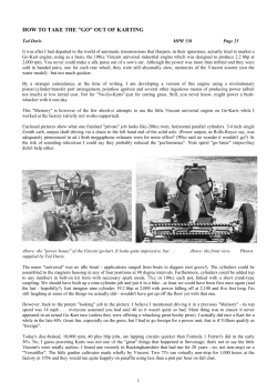


© Copyright 2026