
MV-TRAINER USER MANUAL Version 0.2 – January 2014 Leidy Yanet Serna
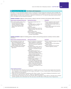
MV-TRAINER USER MANUAL Computational Tool for Modeling and Simulation of Mechanically Ventilated Patients Version 0.2 – January 2014 Leidy Yanet Serna Mauricio Hernández Miguel Ángel Mañanas MV-TRAINER User Manual Content 1. About MV-Trainer ....................................................................................................................1 1.1. Respiratory System Model................................................................................................1 1.2. Ventilatory Modes .............................................................................................................2 1.3. Patient–Ventilator Interaction .........................................................................................3 2. Running MV-Trainer.................................................................................................................3 3. Interactive Panel ........................................................................................................................6 4. Signal Monitor ............................................................................................................................8 5. Saving Simulation Data .............................................................................................................9 6. Contact and Support .............................................................................................................. 10 7. References................................................................................................................................ 11 MV-TRAINER User Manual MV-Trainer User Manual 1 1. About MV-Trainer MV-Trainer is a tool based in mathematical models, developed to make easier the study of the interaction between a mechanical ventilator and a patient. It describes all stages of system development, including simulated ventilatory modes, the pathologies of interest and interaction between the user and the system through a graphical interface implemented using Simulink and Matlab version R2012b or R2013b (© The Mathworks Inc., Natick, MA), which provides a graphical programming environment that promotes modularization of the overall model into hierarchically smaller subsystems. The developed computational tool allows the study of most widely used ventilatory modes and its advantages in the treatment of different kind of patients. The graphical interface displays all variables and parameters in the common way of last generation mechanical ventilators do and it is totally interactive, making possible its use by clinical personal, hiding the complexity of implemented mathematical models to the user. The evaluation in different clinical simulated scenes adjusts properly with recent findings in mechanical ventilation scientific literature. 1.1. Respiratory System Model The model used in this work for the spontaneous respiratory simulation was proposed by (Poon et al. 1992) with the order of describing the stable state respiratory response before stimuli of hypercapnia and exercise. This model has an optimal controller that fits the ventilation in order to minimize the respiratory work and it includes dynamic elements that relate neural activity with mechanical ventilatory characteristics (Younes et al. 1981). Additionally the model distinguishes between the mechanical work of the breathing during inspiration and expiration. Therefore the model not only fits the ventilation, but also the assembly of variables associated with the ventilatory pattern based on the minimum respiratory work (see Figure 1). Logarithmic Coupler Optimal Controller Quadratic Coupler Work Rate Index Neuro-mechanical Efector Gas Exchanger Chemorreceptors Figure 1. Model of the respiratory control system proposed by (Poon et al. 1992) MV-Trainer User Manual 2 1.2. Ventilatory Modes The modes ventilator implemented in MV-Trainer are available in the major modern mechanical ventilators. These are based in three main modes described in Table I: mandatory-synchronized, spontaneous and intermittent-synchronized. The operation of these ventilatory modes and related parameters has been widely described in literature (Tobin 1994, A. Perel et al. 1992, Tobin et al. 1986). The P-CMV and (S) CMV are known as mandatory modes controlled by pressure and volume respectively. These modes allow the synchronization of the patient's inspiratory efforts with the breaths generated by the ventilator. The P-SIMV and (S) SIMV are modes that combine intermittent mandatory breaths controlled by pressure or volume respectively, with spontaneous breaths. In all cases, the synchronization can be adjusted by volume or pressure. In spontaneously (SPONT) all breaths are controlled by the patient. Each ventilatory mode has a set of parameters to be adjusted by physicians depending on the patient condition. MV-Trainer includes all parameters related with each mode, some of them are described in Table I. TABLE I. VENTILATORY MODES MandatorySynchronized PEEP/C PAP I:E Flow Wavefor m Rate ETS Plateau VT Pramp Psupport VENTILATORY MODE Pcontrol CONTROL PARAMETERS Pressure Control x x x x x P-CMV Volume Control x x x x x x (S)CMV Spontaneous Pressure Support x x x x SPONT IntermittentPressure Synchronized Control x x x x x x x x P-SIMV Volume Control x x x x x x x x x (S)SIMV Pcontrol, pressure above PEEP/CPAP to be applied during inspiration. Psupport, pressure above PEEP/CPAP triggered by the patient. Pramp, time required for inspiratory pressure to reach the set pressure. VT, delivered tidal volume. Plateau, pressure after the delivery of the tidal volume but before the patient is allowed to exhale. ETS, expiratory trigger sensitivity. Rate, respiratory frequency. I:E, inspiratory/expiratory ratio. Flow Waveform, defines the waveform supplied by the gas flow MV-Trainer User Manual 3 1.3. Patient–Ventilator Interaction The interaction between the patient and the ventilator involves various subsystems (see Figure 2); ventilatory modes described above and the parameters associated with the ventilator configuration (block 2, Figure 2), respiratory patients with different levels and kind of disease (block 1, Figure 2), and the patient-ventilator interaction (Block 3, Figure 2). Three kinds of patients can be simulated: Chronic Obstructive Pulmonary Disease (COPD), Restrictive Pulmonary Disease (RPD) and arbitrary patients where Ers, Rrs and patient effort are configured by the user. Once ventilatory mode and patient pathology are selected, their interaction can be simulated. Variables such as respiratory frequency, fR and lung volume, Vl, are included in the feedback and they allow the computation of respiratory elastance and resistance continuously during the simulation. That means that the mechanics ventilatory depends of the effect that the ventilator configuration produces. Despite that in this version of MV-Trainer the patient's inspiratory efforts are assisted by the mechanical ventilator, the real interaction between them has not yet been performance because such efforts do not account for work done by machine. The implementation of this interaction is not trivial due to the complexity of the respiratory system. Setting patient activity during Mechanical Ventilation Pathology Respiratory Selection Ventilaroty Mode Selection 2 1 3 Level of EPOC or EPR Respiratory compliance and resistance calculation Ers , Rrs Simulation of ventilatory mode selected Setting control parameters Ers , Rrs f R ,Vl Pvent + Simulation of Patient - Ventilator Interaction Recording parameters and ventilatory variables Pvent , Plung ,VT , Faw , Ers , Rrs , f R ,... Figure 2. Block diagram of the patient-ventilator interaction 2. Running MV-Trainer To begin using MV-Trainer, unzip the “MV_Trainer.rar” file and check that you have all the necessary files. The list of files in “MV_Trainer.rar” file is: MV-Trainer User Manual Files: Sim_Modes.m, Sim_Modes.fig Folders: Functions, Images, ModelsR2012b, ModelsR2013b, work Files in Folder MV_Trainer\Functions\... VentParameters.m VentWaveForms.m --Sub folder ...\GUIDE: MechanicalParameters.m PatternCurve.m Relation.m ModeSelection.m SimulationSetup.m StartSetupMode.m StartSetupPatient.m --Sub folder ...\PoonModel: SfuncPoon.m initopt.m mainpoon.m --Sub folder ...\PoonModel\funcs: PWE.m PWI1.m PWI2.m VExpidot.m chem_plant.m constrfun.m fitfun.m fitfunDATA.m mech_plant.m simulate.m stimvect.m Files in Folder \MV_Trainer \Images\... CNS3.png GIBIC.jpg HG5.jpg Lungs.jpg Pulmon.bmp muscles.jpg patient.jpg udea.png 4 MV-Trainer User Manual 5 Files in Folder MV_Trainer \ModelsR2012b\... MECHPLANT.slxp MONITOR.slxp MVTRAINER.mdl VENTILATOR.slxp Files in Folder MV_Trainer \ModelsR2013b\... MECHPLANT.slxp MONITOR.slxp MVTRAINER.mdl VENTILATOR.slxp After you have unzipped the file, you are ready to run the program in the MATLAB environment, make sure that you are in the Matlab directory where the unzipped files are located. To Open MV- Trainer, in the Matlab command prompt, type (Figure 3): “Sim_Modes.m” Figure 3. Picture that exemplifies how to run MV-Trainer The Control Panel graphic interface and a Simulink model will appear, as shown below. MV-Trainer User Manual 6 Figure 4. Initial GUI (Graphic Interface) Figure 5. MV-Trainer (Simulink Model) 3. Interactive Panel The graphic interface has two main panels: the left one for the configuration of parameters related to the patient and the right one for the mechanical ventilator configuration and visualization of variables (Figure 6). MV-Trainer User Manual 7 0.5 0 15 0.8 0.9 0.1 0.2 10 0.3 0.4 0.5 0.5 0.6 0.6 0.7 0.8 0.9 0.7 MODES 0.8 0.9 SIMULATION 0.8 0 2 4 0 0.1 0.2 0.3 Rate: 10 6 rpm Tinsp: 8 1.67 s PEEP: 10 5 cmH2O 12 ETS: 25% I:E: 2:5 Texp: 4.33 s Plateau: 10% 0.4 0.5 0.6 0.7 0.8 0 VT: 600ml 0.5 0.6 Pramp: 125ms 0.9 1 P 1 [cmH O] aw20 cmH2O 2 Psupport: 0.4 Loop P/V -50 0 500 0 15 VT [ml] 0 0.4 1 5 50 0 50 1 0.6 1 CONTROLS 0.2 2 4 6 8 10 12 0 400 0.2 Vaw[l/s] 5 1 Backup: CMV 15 0 0.7 0.5 0 0.1 0.2 SETTING 0.3 0.4 VENTILATOR 0 0.6 VT [ml] Vaw [l/s] 0.4 0.8 MONITORING: 0 0.5 Paw [cmH2O] V [l/s] Effort Inspiratory Magnitude: 1.5 cmH2O 0.3 VT [ml] 0 10 Respiratory Activity: 0.2 2 2 4 4 6 8 6 8 10 10 1212 8 10 12 VT [ml] [ml] Volume ■1 2 3 4 Vaw [l/s] Disease Level: 0.1 10 300 0 0 0.5 200 1 Paw [cmH2O] 100 5 0 -50 2 4 6 4 6 t [s] 2 4 6 8 10 12 Vaw[l/s] V [ml] 0 500 400 8 10 12 PPressure [cmH2O] aw [cmH2O] Ppeak_aw: 12.03 cmH2O 0 0 2 4 6 8 10 12 300 Pprom_aw: 8.52 cmH2O Pmin_aw: 5 cmH2O 200 Pmin_Lung: 7.63 cmH2O VPlung T [ml] [cmH2O] 15 VT [ml] EPR 1 0 0 [ml] VTPaw [cmH2O] Respiratory Pathology: 1 0.5 1 ■EPOC 0 VT [ml] PATIENT SETTING 1 Paw [cmH2O] MV-TRAINER Paw[cmH2O] Paw[cmH2O] 1 0.5 PEEP: 5 cmH2O 10 100 R: 6.42 cmH2O/l/s 5 0 2 4 6 8 10 8.4 s APNEA SIMV 12 4 l/cmH2O 6 8 C: 0.07 RC: 0.48 s Time (s) t [s] SIMULATE STOP 10 12 Paw [cmH2O] CANCEL EXIT Figure 6. Graphical interface of MV-Trainer. Left panel, for patient selection and right panel, for mode selection and parameters of ventilation setup. The right panel has tree tabs: the first one, Modes, allows the ventilatory mode selection among the modes presented in Table I, the Controls tab allows setting the mechanical ventilator parameters associated with the ventilatory mode selected; and the third tab, Simulation, shows all resulting variables in graphical and tabular ways for their monitoring: airway and lung pressures, volume, flow and XYcurve of Volume vs. Pressure (Figure 6). Figure 7 shows the parameters control for SIMV mode. The user can select the inspiratory flow pattern through the selection box “FlowPattern” and adjust the value of the parameters either by using the slider bar or by typing directly into the box. Both the “min” and the “max” values are shown for each slider bar and represent the range of values that the user can configure. The values that fall within the default spans indicated are recommended, since these are consistent with physiologically feasible ranges. MV-Trainer User Manual 8 Figure 7. Parameters control for SIMV mode, intermittent mandatory controlled by volume mode The virtual tool allows the change of patient and ventilator configuration in an interactive way, i.e. the user can change values during the simulation. 4. Signal Monitor The tab “Simulation” shows all resulting variables in graphical and tabular ways for their monitoring, these are (see Figure 8): Airway pressure Lung Pressure Volume Flow XY curve of Volume vs. Pressure The resulting variables in tabular ways are: Respiratory rate Inspiratory time Expiratory time Tidal Volume Peaks pressure MV-Trainer User Manual 9 Mean pressure AutoPEEP Respiratory Resistance (Rrs) Respiratory Compliance (Crs) Time Constant (RC)… Figure 8. Panel “Simulation” that shows all resulting variables in graphical and tabular ways for their monitoring 5. Saving Simulation Data The data resulting of the simulation can be saved through of the Matlab commands. In the workspace are shows all resulting variables of the simulation. These can be saving by writing in the command window (see Figure 9): “save variable_name file_name.mat” Where variable_name is the variable name that wish saved and file_name is the file name whose extension is .mat. The main variables of the simulation model are: MV-Trainer User Manual 10 Paw: Airway pressure. VT: Tidal volume. Flow: Airway flow. PLung: Lung pressure. Rrs: Resistance of respiratory system. Ers: Elastance of respiratory system. Figure 9. Saving data with Matlab® commands. 6. Contact and Support For questions and suggestions about MV-Trainer can send your valuable comments and feedbacks to mail [email protected] or [email protected]. Once we have the solution, then we will post it so that other users can benefit from it. MV-Trainer User Manual 11 7. References A. Perel and Ch. Stock., 1992. Handbook of Mechanical Ventilatory Support. W.a.W. BALTIMORE ed., ISBN 0-683-06856-3. POON, C.S., LIN, S.L. and KNUDSON, O.B., 1992. Optimization Character of Inspiratory Neural Drive. J Appl Physiol, 05/01, vol. 72, no. 5, pp. 2005-2017. TOBIN, M.J., 1994. Principles and Practice of Mechanical Ventilation. McGraw-Hill ISBN 007064943X. TOBIN, M.J., et al, 1986. The Pattern of Breathing during Successful and Unsuccessful Trials of Weaning from Mechanical Ventilation. The American Review of Respiratory Disease, 12, vol. 134, no. 6, pp. 1111-1118. YOUNES, M. and RIDDLE, W., 1981. A Model for the Relation between Respiratory Neural and Mechanical Outputs. I. Theory. J Appl Physiol, 10/01, vol. 51, no. 4, pp. 963978.


© Copyright 2026