
SAFETY AND INSTALLATION MANUAL
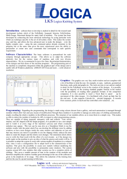
SAFETY AND INSTALLATION MANUAL Photovoltaic Module FU XXX Author: Futura Document Name: 2014_05_19_FU_XXX_installation_manual Revision Date: 19/05/2014 SAFETY AND INSTALLATION MANUAL FOR PHOTOVOLTAIC MODULES FU XXX CONTENTS CONTENTS ......................................................................................................................................... 1 1. General Information ......................................................................................................................... 3 2. Disclaimer of Liability ....................................................................................................................... 4 3. IEC 61216 & 61730 certifications ..................................................................................................... 4 4. Limited Warranty .............................................................................................................................. 4 5. Module Specification ........................................................................................................................ 4 6. Safety Precautions ........................................................................................................................... 4 7. Installation ........................................................................................................................................ 5 8. Use and Maintenance ...................................................................................................................... 7 9. Packaging, Handling and Storage of Modules ................................................................................. 8 2 © 2014 Futura Holding LTD. - Specifications in this manual are subject to revisions without notice SAFETY AND INSTALLATION MANUAL FOR PHOTOVOLTAIC MODULES FU XXX caused by obstacles in and around the area of installation. 1. General Information The photovoltaic (PV) modules FUTURA FU XXX EU, FU XXX EU-M, FU XXX P and FU XXX M (hereafter “FU XXX”) are devices that produce electrical energy by converting the sunlight’s radiation reaching their surface, when appropriately exposed, into continuous/direct current (DC). The FU modules are intended to be used only and exclusively in photovoltaic module systems connected to the electrical grid; therefore, it is not recommended to use them in battery powered photovoltaic module systems (stand alone). The rated currents at Standard Test Conditions (STC) of the FU modules are variable depending on the model and the relative power rating, as indicated in the respective technical data sheets. Most of the electrical parameters of the modules, specified in the datasheets, are determinable only by using special instrumentation in the laboratory; therefore, only some of them are measurable outside of a lab, using common instrumentation (voltmeter, AM meter, solarimeter/pyranometer). Fig. 1: IV curve at different irradiance A high ambient temperature and therefore, an increased operational temperature of the modules, also contribute to a proportional reduction in electrical performance. In order to optimize the production of electical energy of the modules, and therefore of the system connected to an electrical grid, it is the responsibility of the installer to make sure the modules are positioned as much as possible facing south, with the tilt angle (β) (inclination of the surface of the modules in respect to the ground, as shown in Fig.2) optimal for the type of desired application. It is possible, following very precise procedures, to carry out electrical measurements of voltage and current as snapshots, which enable you to monitor the operation of the modules and determine possible, although rare, anomalies. The electrical output parameters for FU modules, of technical importance during the operation, installation and maintenance, are the following: The tilt angle of ideal average throughout Italy is β = 30°; however, even the inclination typical the roof of a dwelling (β = 15-20°), being already an inclined plane, could make the angle acceptable, if not ideal, for the installation of coplanar modules on it (using a special standard structure for support). Voltage at open circuit (Voc) Current at short circuit (Isc) Voltage at point of maximum power (Vmpp) Current at point of maximum power (Impp) Solar radiation in W/m2 at the time Temperature of the cells Depending on the variation of the tilt angle of the modules with respect to the ground, or of their orientation in relation to facing south (Azimuth), there will be changes in the annual average amount of energy produced by the modules themselves, and therefore, of the plant connected to the network to which they are linked. The general performance of the modules is heavily dependent on the intensity of the incident solar radiation, as illustrated in Fig.1. Acheiving maximum performance requires proper installation, with the modules oriented towards the South and their surface exposed as perpendicularly possible to the incident rays of the sun; furthermore, avoiding any shading 3 © 2014 Futura Holding LTD. - Specifications in this manual are subject to revisions without notice SAFETY AND INSTALLATION MANUAL FOR PHOTOVOLTAIC MODULES FU XXX 6. Safety Precautions Installation should be performed only by authorized personnel! Module installation must be performed in compliance with the latest IEC code (CEI in Italy) Within the modules, there are no user serviceable parts. Do not attempt to repair any part of the modules. Contact your module supplier if maintenance is necessary In order to reduce the risk of electric shock, prior to installing the modules, remove metallic jewelry and use insulated tools during installation. Do not expose the modules to artificially concentrated sunlight! Do not stand on, drop, scratch, or allow objects to fall on the modules. Do not lift the modules at the connectors or junction box! Do not install or handle the modules when they are wet or during periods of high winds. Do not use oil-based lubricants on any part of the junction box as this can cause long-term damage to the plastics. Ensure that wire cable connections are routed in accordance with the junction box manufacturer’s recommendations. Incorrect routing of the wire cable can lead to stress damage to the junction box. Do not leave cable connectors exposed in adverse climatic conditions. Water and dust deposits inside the cable connectors can cause long-term damage. Broken module glass, a torn backsheet, a broken junction box or broken connectors are electrical safety hazards; consequently, contact with a damaged module can cause electric shock. The total voltage of modules connected in series corresponds to the sum of the voltages of the single modules; whereas connecting the modules in parallel results in adding up the currents. Consequently, strings of interconnected modules can produce high voltages and high currents and constitute an increased risk of electric shock and may cause injury or death. For installation, maintenance, or before making any electrical connection or disconnection, ensure all modules in the PV array are exposed to a light intensity that is less than 400 W/m2!! If necessary, the modules should be covered with an opaque cloth or other material in order to shield them South East Fig. 2: Orientation Vs. Azimuth 2. Disclaimer of Liability Since the methods of system design, installation techniques, handling and use of this product are beyond company control; FUTURA does not assume responsibility and expressly disclaims liability, for loss, damage or expense resulting from improper installation, handling or use. 3. IEC 61216 & 61730 certifications This product meets or exceeds the requirements set forth by IEC 61215 and 61730 for PV Modules. These standards cover flat-plate PV modules and panels intended for installation on buildings or those intended to be freestanding. This product is not intended for use where artificially concentrated sunlight is applied to the module. 4. Limited Warranty Please refer to FUTURA General Terms and Conditions of Sale for details of the modules’ limited warranty. Failure to comply with this Safety and Installation Manual will invalidate FUTURA Warranty for the PV modules as stated in the General Terms and Conditions of Sale. 5. Module Specification Please refer to the technical datasheet for the module FUTURA FU XXX respectively for electrical performance data. These electrical data are measured under Standard Test Conditions (STC) of 1000 W/m2 irradiance, with Air Mass (AM) of 1.5 spectrum, and a cell temperature of 25°C. 4 © 2014 Futura Holding LTD. - Specifications in this manual are subject to revisions without notice SAFETY AND INSTALLATION MANUAL FOR PHOTOVOLTAIC MODULES FU XXX from exposure to light intensity greater than 400 W/m2. 7. Installation 7a) Module Mounting The module is class C fire rated. When installing FU modules, local building code requirements and regulations must be adhered to at all times. In particular, in case of roof mounting, fire protection must be compatible with the class C fire rating. Class C rating is maintained for mounting of the modules with any inclination angle. Sufficient ventilation of the module backside is required and the mounting configuration (e.g. sufficient clearance) should be adapted accordingly. Do not drill any additional holes into the module frames and do not cover the drainage holes. Pre-assembled mounting systems have been confirmed by FUTURA in writing in advance The modules can be mounted in every angle from horizontal to vertical, avoiding configurations with the junction box up-side down at all times (e.g. trackers with “sleep mode”). In order to maximize module exposure to direct sunlight, the modules should be oriented to the south in the northern hemisphere and to the north in the southern hemisphere. Mounting Methods: Mounting using mounting holes: Each module must be securely fastened at a minimum of 4 points. Use the 4 mounting holes (slots, see Fig. 3) on the PV module frame to bolt the module with stainless steel screws and nuts to the mounting framework. The distance of the mounting holes has been designed in order to result in a uniform wind and snow load without damaging the module. Do not drill additional holes in the module frame; doing so will void the warranty. longer sides facing each other) configuration. (It is recommended to always use stainless steel screws and bolts.) The modules can be mounted on continuous base structures (inclined or horizontal) such as rails or similar. Both base structures must be mounted at the same distance from the symmetrical axis (vertical or horizontal) of the module. In vertical configuration, it is strongly recommended to place the supporting elements nearby the mounting holes, or in any case, allow a spacing of 800-1100 mm between them. This is necessary in order to maintain a correct load distribution. In horizontal configuration, fixing the modules by blocking them at the 4 mounting holes will guarantee the characteristics regarding the static loads as certified. When clamping the modules in horizontal configuration on a support structure, the following rules have to be applied in order to maintain the resistance against static loads as certified: o If the bars or rails are in vertical direction, they have to be placed nearby the corner holes or in any case a spacing of 800-1100 mm between the bars has to be maintained. o If the bars or rails are in horizontal direction, they have to be placed with a spacing of 500-750 mm (with this mounting variant the wind and snow load limit is reduced to 2400 Pa). The modules can also be fixed by placing them with their frame on a structure that is supporting the two sides of the frame over their whole length. In this case, the position of the mounting clamps must be in accordance with the above mentioned spacings (800-1100 mm and 500-750 mm respectively). At least 20 mm spacing must be maintain between modules ATTENTION: in the case of installation with modules in the vertical position, it is preferable to maintain the Junction Box located in the upper part of the module. This practice will help reduce, as much as possible, contact between any standing water and the Junction Box, and avoid possible water infiltration. Mounting using clamping method: FUTURA recommends the use of clamps. When using clamps, it is possible to mount the modules in horizontal (the shorter side of one module facing the shorter side of the neighboring module) or in vertical (the 5 © 2014 Futura Holding LTD. - Specifications in this manual are subject to revisions without notice SAFETY AND INSTALLATION MANUAL FOR PHOTOVOLTAIC MODULES FU XXX During the wiring and installation of the modules use caution! Do not trample on or scratch the modules. Do not drop sharp or heavy objects on either surfaces of the module. Do not subject the modules to any impact, in particular in the vicinity of the edges of the frames and do not flex them mechanically. The modules are made of a single laminate, therefore once damaged, they are not repairable. In the event of any damage to either the front or the back of the module, the part exposed might be electrically active and therefore dangerous, especially if the module is connected in series to a string. 7c) Electrical Connection Danger! Risk of serious injury or death from electric shock or electric arc flash! Do not connect or disconnect modules under load! Even if the modules are protected against accidental contact, under unfavorable conditions high hazardous voltage (several hundreds of volts) may occur during installation. Consequently, installation and maintenance of the modules, as well as the connection to the main power supply, may only be performed by authorized and qualified persons. Before connection of the system to the grid, the PV system must be approved for correct installation, by an electrician responsible to the operator and the local electricity company. Fig. 3: Mechanical drawing of an FU module showing the mounting holes, the drainage holes, and the ground connection holes. See the table below. (mm) A B C D Z FU xxx EU 992 1640 275 1090 40 FU xxx P 990 1650 300 1050 40 FU xxx IT 998 1663 400 863 35 The design of the PV system should be done by a qualified person familiar with PV system design. The system design is the responsibility of the PV system designer. Therefore, FUTURA does not assume any liability for how the modules are installed. 7b) Handling of Modules The FU modules are robust, but in particular, the glass front cover may be subject to damage if improperly handled or installed. Wear protective gloves when handling and installing the modules in order to be protected against cutting by sharp edges and against skin burns. Handle the module in a way that avoids breakage or scratching of the front cover glass and mechanical damage to any other part of the module. Do not carry the module by its connector wires in order to avoid the risk of electric shock and prevent damage to the module. Under normal conditions, a PV module is likely to experience conditions that produce more current and/or voltage than reported at STC. Accordingly, the values of Isc and Voc marked on the module should be multiplied by a factor of 1.25 when determining component voltage ratings, 6 © 2014 Futura Holding LTD. - Specifications in this manual are subject to revisions without notice SAFETY AND INSTALLATION MANUAL FOR PHOTOVOLTAIC MODULES FU XXX conductor current ratings, fuse sizes, and size of controls connected to the PV output. 220V AC - 50Hz to provide energy to the local electricity grid. Also note: Grounding: The module frame or array must be grounded before wiring. For grounding, use material that is certified according to CEI 82/25 or applicable national codes – in particular the grounding should be performed by a qualified electrician. Ensure that the grounding area for the wire is clean and free from oxides or any debris that could impede the electrical grounding. Attach a separate approved ground wire to one of the holes marked with ground label on the module frame with an IEC approved ring terminal or IEC listed grounding lug. 8b) Operational Measurements The only two electrical parameters of output from a PV module, measurable with conventional instrumentation, are the Voc and Isc. When the PV modules are instead connected in series/parallel configuration to an inverter, from its display it is possible to read: Operational voltage at maximum power output (Vmpp) of the string Operational current at maximum power output (Impp) of the string From these above values, it is possible to estimate the voltage at maximum power (Vmpp) of a module in the string under review and any non-uniformity in the voltages (Vmpp) of multiple strings connected to the same inverter. Voc should be increased by a factor according to the lowest ambient air temperatures expected for the installation site. Refer to CEI 82/25 for the correct Voc correction factor according to the respective temperatures. If this information is not available, a 1.25 multiplying factor can be used as default value for correction of Voc. From the Impp for the string it is also possible to verify whether there are obvious differences between one string and another. When a uniform condition is detected, it can be assumed that all the modules are working properly. In order to obtain the required electrical current and/or voltage, the modules can be connected in series, in parallel, or in a combination of both. o In the case of series connection, do not exceed the maximum system voltage of 1000 V even at low temperatures. Always use the same type and rating of module in one installation! o In the case of parallel connection of modules or series strings of modules, fusing may be required. The following measures serve to collect preliminary information on the operational status of the PV modules in a PV system. If there is a need to perform direct measurements on individual modules using conventional instrumentation, the following action should be taken. To measure the open circuit voltage (Voc): Note: even in the presence of an insolation average of 500 W/m2, a module exposed to the rays of the sun presents at its poles (+ and –) a Voc very close to the nominal value at STC (as shown in Fig.3). The voltage of the strings of modules, in series, when measured at their poles, is the sum of all the individual voltages of each module. This total voltage should be compatible with the range of input voltages admissible for the inverter to which the modules are connected. When taking the temperature at which the module is working at that moment into account, the open circuit voltage module (Vocmod) will be approximately equal to: Vocmod = VocSTC – [(Tmod – 25°C) x 0.125V] Where: o VocSTC is the open circuit voltage measured at STC; o -0,125V/ °C is the average variation of Voc of a module for a variation in temperature of 1°C; o 25°C is the reference temperature of STC; 8. Use and Maintenance 8a) Intended Use FU modules are designed for use in gridconnected systems. They are therefore linked in series/parallel combinations to feed a dedicated inverter with a DC input and an AC output of 7 © 2014 Futura Holding LTD. - Specifications in this manual are subject to revisions without notice SAFETY AND INSTALLATION MANUAL FOR PHOTOVOLTAIC MODULES FU XXX o In the case of good solar radiation and at the ambient temperature (Tamb), one can estimate the temperature of the module as follows: Tmod = Tamb + 30°C 8c) Maintenance Although PV modules do not require any routine maintenance, periodic (annual) inspection for damage to glass and inspection of the electrical connections and for corrosion as well as the mechanical connection is recommended. Using the calculations above, it is possible when measuring with a multi-meter, to verify Voc meets the standard shown in the module datasheet. In a case that the Voc to the connectors is decidedly lower than the standard values (75% or less) this could represent a condition of anomaly which should be investigated more thoroughly. Under normal conditions (sufficient rainfall), cleaning of the module is not required. In extreme climatic conditions, the electrical performance of the module may be affected by accumulation of dirt on the glass front cover. In this case, the front cover can be washed using water (no aggressive cleaning solutions, chemicals or abrasives!) and a soft cloth. Exercise extreme caution when applying water on any electrical device!! To measure the short-circuit current (Isc): A PV module exposed to the south, inclined perpendicularly to the rays of the sun, in the middle of the day (about 12:00 to 1:00 PM ) and in conditions of good weather, presents a value of Isc similar to the rated values at STC, as measurable with an amp-meter in continuous current. By measuring the solar radiation (E) effective at the moment with a solarmeter/pyranometer in W/m2 the short circuit current of the module at the moment Iscmod should be very close to the following value: ATTENTION!!!!! To avoid the phenomena of electric arcing, both the connection and disconnection of the connectors of the modules being tested and the measurements of Voc and Isc should be performed with the string of modules in conditions of open circuit. In addition, the Isc should be measured for each individual module in conditions of open circuit and not to the extreme poles of the string, which could be affected by voltages up to 1000V. Iscmod = IscSTC x E/1000 Where: o IscSTC is the short circuit current measured at STC; o 1000 W/m² is the radiation at STC. 9. Packaging, Modules Handling and Storage of 9a) FUTURA's Packaging The measurement of the Isc is executable with precision only when using a solarmeter/pyranometer which gives exact information on the conditions of solar radiation at the moment, otherwise it is not reliable. In the case of the unavailability of a solarmeter/pyranometer, it will only be possible to have an estimate of the functionality of the module by comparing the value of Iscmod measured in relation to those of the other modules of the PV system, measured under the same conditions of irradiation. The acknowledgment of any obvious discrepancies of Isc in the modules thus serves to identify anomalies. FUTURA provides the FU modules in the most appropriate packaging, designed to guarantee that the transportation and storage will be in conditions of maximum safety and protection until the time of installation. Transport the module in its original packaging until installation. Protect all parts of the module during transport and installation from mechanical stresses. 9b) How to Manage the Packaging Each package has been designed to allow the shipment and storage of modules in order to maintain their integrity unchanged over time, provided that the information and indications supplied by FUTURA are closely observed and followed. These indications are summarised by a series of standard symbols posted in a visible manner on each pallet. The list below illustrates 8 © 2014 Futura Holding LTD. - Specifications in this manual are subject to revisions without notice SAFETY AND INSTALLATION MANUAL FOR PHOTOVOLTAIC MODULES FU XXX the meaning of each symbol (you can find some of them in each pallet): that are damaged or are no longer usable for materials. DO NOT STACK: each pallet of modules is packaged according to the maximum number of modules stackable vertically, in order to avoid or reduce mechanical stress or damage as a result of the pressure exerted by the stacked modules. Therefore, it is absolutely forbidden to stack a pallet on top of another, both in the process of shipment and storage of modules. FRAGILE: the photovoltaic modules are manufactured using a glass front which makes up approximately 70% of the total materials used to construct them. Although the modules are stiffened by an aluminium frame, any direct impact to the glass or on the corners of the modules should be avoided. Avoid flexing the laminates or applying non distributed loads and stresses. Avoid scratching the surface of the exterior glass or backsheet. Do not apply any forces to the backsheets. DO NOT EXPOSE TO ATMOSPHERIC AGENTS: each pallet of modules is suitably dressed in a cap of transparent plastic in order to avoid temporary contact with generic water spray or atmospheric agents. The plastic casing does not ensure the protection of the modules in the case of prolonged exposure to atmospheric agents. Similarly, in the case of flooding, the pallet does not ensure the maintenance of the mechanical properties of the weight of the modules. For this reason it is recommended to store the pallet in a place that is sheltered and dry. In addition, as the the junction box has an IP65 degree of protection, in the event of a flood the stagnant water inside of the frame could oxidise the metal contacts of the connectors degrading the characteristics and altering the electrical properties of the contacts of the module causing damage. HANDLE WITH CARE: during the operation of shipping and storage of the modules use maximum care to ensure the full integrity of the modules. 9c) How to Handle the Pallet During the handling of the pallet make sure to pay the utmost attention. The packaging must be raised/moved exclusively with fork-lift trucks or hand pallet trucks fitted with forks of length appropriate to its size and weight. Pay attention during the stages of handling and unpacking. Verify that the package is positioned on a surface that is either flat or not excessively deformed to a point that would impart an inclination to the pallets which could damage the PV modules. DO NOT OVERTURN THE PACKAGING: the packaging is only designed to be handled and stored with the modules maintaining the position of the arrow printed on the packaging, with the arrow always facing upwards. Not following these indicated directions may create forms of mechanical stress on the modules that could cause damage or breakage. FUTURA DOES NOT ASSUME RESPONSIBILITY IN THE EVENT OF DAMAGE TO THE MODULES ARISING FROM MANAGEMENT OF THE PACKAGING THAT IS IMPROPER OR DIFFERENT FROM WHAT WAS STATED IN THIS DOCUMENT. RECYCLABLE: most of the photovoltaic modules are recyclable. They should not be thrown into landfill without a proper method for recycling. Although they are not yet regulated by current rules of refutes RAEE, many institutions and public structures are organising to collect the modules 9d) Unpackaging Observe the following procedures for the unpacking of modules: Place the packaging on a stable and flat surface 9 © 2014 Futura Holding LTD. - Specifications in this manual are subject to revisions without notice SAFETY AND INSTALLATION MANUAL FOR PHOTOVOLTAIC MODULES FU XXX Using a cutter, cut the plastic wrap surrounding the package or to open the paper box Remove the plastic wrap Remove the upper cover Recover the flash list (for record keeping) Using a cutter, cut the straps Remove the PV modules and their protective corners without damaging Note: avoid storing partial packaging! Once you have removed the strapping the packaging must no longer be moved!! 10 © 2014 Futura Holding LTD. - Specifications in this manual are subject to revisions without notice Please conserve a copy of this manual at the location of the PV System! Author: Futura Document Name: 2014_05_19_FU_XXX_installation_manual Revision Date: 19/05/2014


© Copyright 2026