
Manure Spreader Model 27G
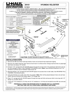
Farmer Helper Compact Manure Spreader 27G
9-26-2014
Manure Spreader
Model 27G
Read and follow the instructions in this manual before operating the equipment.. Failure to follow
the instructions in the manual may result in serious injury.
Features and specifications may be changed at any time without notice being given.
Betst Products, llc. 83371 Melton Rd, Creswell OR, 97426. Phone: 541-895-3083
www.value-leader.com
1
Farmer Helper Compact Manure Spreader 27G
9-26-2014
Contents
Guide to this Manual...........................................................................3
For Your Safety...........................................................................................................................................3
Safety Labels.........................................................................................................................................4
SECTION 2: OPERATION..................................................................7
Understanding Spreader Operation...........................................................................................................7
The Spreader Operating Components................................................................................................7
Connecting the Spreader to the Towing Vehicle...............................................................................7
Guidelines for Loading the Spreader for Operation..........................................................................8
Operating the Spreader......................................................................................................................9
SECTION 3: MAINTENANCE & ADJUSTMENT.........................10
Guidelines for Regular Maintenance.......................................................................................................10
Procedures for Spreader Adjustment................................................................................................12
Adjusting the Rear Pawl....................................................................................................................12
Re-installing the Beater Drive Chain................................................................................................13
APPENDIX A: PARTS REFERENCE............................................14
General Spreader Specifications..............................................................................................................14
Ordering Information...............................................................................................................................15
Spreader Box, Hitch Assembly and Spreader Controls....................................................................15
Axle, Wheel and Safety Shield Assembly..............................................................................................17
Apron Chain Drive Group........................................................................................................................19
Beaters and Drive Assembly....................................................................................................................21
Jack Stand & Dolly Wheel........................................................................................................................23
Manual End Gate....................................................................................................................................24
2
Farmer Helper Compact Manure Spreader 27G
9-26-2014
SECTION 1: INTRODUCTION
Guide to this Manual
This m anual contains all the information necessary to safely operate and m aintain the F a r m e r H e l p e r 27+ or 37+
Spreader. Consult the Table o f Contents for a detailed list of topics covered. You'll find this m anual's step-bystep procedures easy to follow and understand. Should questions arise, please contact Betst Products before
starting any o f the procedures in this manual.
NOTE: Procedures provided in this manual apply to both spreader models (Model 27+ and Model
37+) unless specifically noted otherwise.
R egarding the inform ation presented in this m anual:
All safety, operating, and servicing inform ation reflects current production m odels at the tim e
o f publication o f this m anual.
R eferences m ade to left, right, front, and rear are those directions view ed w hen facing the
unit from the rear.
Please read all sections in the manual carefully—including the important safety information found
in this section—before beginning any procedures; doing so ensures your safety and the optimal
performance o f your Farmer Helper Spreader.
For Your Safety...
F or your safety, F a r m e r H e l p e r docum entation contains the follow ing types o f safety statem ents (listed
here
in order o f increasing intensity):
N O T E : A clarification o f previous inform ation or additional pertinent inform ation.
AT T E N T IO N : A safety statem ent indicating that potential equipm ent dam age m ay occur if
instructions are not followed.
C A U T IO N : A safety' statem ent that rem inds o f safety practices or directs attention to unsafe
practices w hich could result in personal injury if proper precautions are not taken.
WA R N IN G : A strong safety statem ent indicating that a hazard exists w hich can result in
injury or death if prop er precautions are not taken.
D A N G E R ! The utmost levels o f safety must be observed; an extrem e hazard exists which
w ould result in high probability o f death or irreparable serious personal injury if proper
precautions are not taken.
The best operator is a careful operator. By using com m on sense, observing general safety rules, and
3
Farmer Helper Compact Manure Spreader 27G
9-26-2014
For Your Safety... (continued)
In addition to observing the specific precautions listed through out the m anual, th e following gen eral
p re c a u tio n s a p p ly a n d must be heeded f o r p r o p e r , safe o p eratio n .
WA R N IN G : K eep hands and feet from under the spreader at all tim es. Ensure that you are
safely distanced from any other persons before operating the spreader.
WA R N IN G : D O N O T attem pt to operate the spreader in areas w ith steep inclines, ditches,
large rocks, stum ps, or holes w hich m ay endanger the operator by upsetting the tractor or cause dam
age to the spreader.
W A R N IN G : To prevent serious personal injury and to prom ote safe spreader operation, keep all
shields in place during operation. Ensure that all m ounting hardw are is properly tightened.
WA R N IN G : N ever clean, adjust, or repair the spreader w hile the tractor is running.
WA R N IN G : N ever get off th e tractor w hile it is in m otion and/or w hile the spreader is in operation.
WA R N ING : N ever w ear loose clothing w hen operating the spreader as it may becom e caught
in the m oving parts o f the machine.
WA R N IN G : N ever allow children or anyone else to ride on the spreader.
AT T E NT ION : For proper and safe operation o f th e spreader, periodically inspect all parts for
excessive w ear. Replace w orn com ponents w ith factory-authorize parts.
AT T E NT ION : To prevent the hitch from com ing disconnected during operation, use the proper size hitch pin
w ith a safety cotter at all tim es.
Safety Labels
Follow ing are the locations and descriptions o f all labels on the spreader (labels are identical for both M odels
2 7 + and 3 7 + );refer to Figure 1A. Please note that som e labels denote m odel num ber, m odel description, etc.
while others contain important safety messages.
Each Safety L a b e l contains an im portant safety m essage starting w ith a key w ord as discussed earlier in this
section (e.g. ATTEN TIO N , CA U TIO N , WA R N IN G , D A N G ER). F or you r safety and the safe operation o f
your equipm ent, review all labels and heed all safety m essages as printed on the labels.
B e sure to keep the safety labels clean and readable. I f the labels ever becom e dam aged or illegible, contact
Betst Products for replacem ents.
4
Farmer Helper Compact Manure Spreader 27G
9-26-2014
Safety Labels (continued)
S p r e a d e r Safety L ab els
Label P art#
42792
42710
42756
42772
42814
42700
42815/42816
42817/42818
Description
D A N G E R -N O riders
WARNING - Flying Debris
WARNING - Entanglem ent, Do NOT operate w ithout shields
WA RN IN G - Spreader com bination safety label - m oving parts, read manual
ATTEN TIO N - D o N O T exceed specified speed
F a r m e r H e l p e r Logo Label
Spreader Serial N um ber Label
Spreader Model N um ber Label
42815 - 27
42816 -
1-86259
42817 42818 - 37
37
27
F ig u re 1A - S p r e a d e r S afety L a b e l L o catio n s
For your safety, be sure to locate all safety labels and review their content before proceeding with
operating the spreader!
5
Farmer Helper Compact Manure Spreader 27G
9-26-2014
6
Farmer Helper Compact Manure Spreader 27G
9-26-2014
SECTION 2: OPERATION
Understanding Spreader Operation
Proper and safe operation o f th e F a r m e r H e l p e r 27G Spreader requires: (1) being fam iliar w ith the
spreader's
operating com ponents and (2) heeding all safety precautions as stated in this manual.
The Spreader Operating Components
By definition, the left and right sides o f the spreader are determ ined while sitting on the tractor seat.
The follow ing operating com ponents are included with all M odel 21+131+ spreaders:
The left h a n d s p r e a d e r lev er engages thefloor apron chain which moves the manure to the
rear o f the spreader and into the beater.
The r ig h t h a n d s p re a d e r lev er engages the chain that drives the beater and spreads the
manure.
The follow ing are optional operating components included w ith some M odel 21+131+ spreaders (depending on
the specific model configuration ordered):
The jack s tan d d o lly w h eel o p tio n allow s easy m ovem ent o f the spreader around the stable
or bam ; also adjusts the height of the spreader to facilitate hook-up to the spreader tow ing vehicle.
The en d g ate helps to contain loads betw een spreading and also shields the operator during
spreading.
Connecting the Spreader to the Towing Vehicle
For operation in the field, the F a r m e r H e l p e r M odel 27G spreaders can be tow ed by a num ber o f vehicles-garden tractor, A TV , or utility vehicle. Please adhere to the follow ing procedure for connecting the spreader to
your tow ing vehicle. Attaching the spreader to the towing vehicle as instructed is necessary fo r safe
and proper operation o f the equipment.
1.
2.
Back the tow ing vehicle within a few inches o f the spreader hitch.
R efer to Figure 2A. D eterm ine the spreader hitch position required to allow the spreader to remain
parallel to the ground w ith relation to the tow ing vehicle.
N O T E : A s show n in Figure 2A , the adjustable hitch on the front o f th e spreader m ay be positioned in
A num ber o f w ays, by sliding up/down or inverting, to achieve a higher or lower positioning of the
Figure 2A - Adjusting the Hitch Position
7
Farmer Helper Compact Manure Spreader 27G
9-26-2014
Attaching the Spreader to the Towing Vehicle (continued)
4.
R efer to Figure 2B. A djust the overall height o f the spreader/hitch w ith the dolly w heel/jack so the
height o f the spreader hitch m atches the height o f the tractor drawbar or vehicle hitch point (as
applicable).
N O T E : The Jack is held in its upright position w ith a spring-loaded pin. To release the jack
to m ove it into its operational position, sim ply pull the pin outward and sw ing the jack dow n.
F ig u re 2B - U sing th e Jack Stand with Dolly Wheel
5.
6.
7.
8.
Back the tow ing veh icle into the hitch until the holes of the spreader hitch line up w ith the vehicle hitch
point.
Fasten the spreader hitch to the vehicle draw bar/hitch point w ith a hitch pin that fits securely (i .e. so that
it will not com e out during spreader operation) and lock in place with the safety clip.
WA R N IN G : D am age to the spreader or other vehicle, as well as injury to the operator, m ay occur if
A properly-sized hitch pin is not installed as recom m ended. N ote that the installation o f the safety clip to
hold the hitch pin in place is also required for safe spreader operation.
Rem ove the w eight from the Jack /Dolly Wheel by lowering he spreader hitch on the vehicle draw bar/
Hitch point.
T o provide adequate ground clearance for operation, swing the j ack up into its resting
position (i.e. pull the spring-loaded pin out to release the jack and swing the jack upw ard, then allow
Th e p in to re-engage to h o ld th e jack in its upw ard position.)
Guidelines for Loading the Spreader for Operation
F a r m e r H e l p e r recom m ends that you load the spreader from the front toward the back to
facilitate
Easier unloading.
AT T E N T ION : N E V E R store m anure in the spreader between unloading tim es during critical cold
W eather m onths w hen a frozen load could result in severe equipm ent dam age (i.e. tom floor apron
chain).
D O N O T store w et m anure in the spreader (or keep the spreader outdoors w ith m anure in it)—
8
Farmer Helper Compact Manure Spreader 27G
9-26-2014
Operating the Spreader
Before proceeding with operation of the spreader, review all safety statements
as provided in Section 1 of this manual.
WA R N IN G : To prevent serious personal inj ury, ensure that A LL safety shields are in place on the
spreader before starting operation. N E V E R operate the spreader w ithout ALL safety shields in place.
AT T E NT ION / C A U T IO N : In order to obtain proper, aggressive spreading action, the spreader ground
speed must reach a minimum o f 3.0 miles per hour—the equivalent o f a comfortable walking pace.
(N ote th at the w heels drive the beater action.) H ow ever, spreading at speeds over 5.0 m iles per hour (i.e.
Sim ilar to a very brisk w alking pace) can cause excessive w ear or dam age to the equipm ent, w hich m ay void
Your warranty.
1.
2.
3.
4.
5.
6.
7.
8.
9.
10.
Ensure that the spreader (and tow ing vehicle) are in a stopped position (i.e. N OT in m otion).
L if t the m anual end gate.
(Optional equipment)
Engage the right lever to start the beater.
Engage the left lever to start the action o f the apron floor chain (m oving the m aterial towards the rear
o f the spreader).
Begin m oving forward, and ensure that you are reaching the optimal operating speed for spreading
(at least 3.0 m ph, but not m ore than 5.0 m ph ). Rem em ber that this optim al speed is sim ilar to a
comfortable walking ace.
W hen the spreader is alm ost empty and there is very little m anure pushing against the beater,
disengage the right spreader lever (w hich controls the beater rotation).
A llow the apron chain to run the rem aining m anure out the back o f the spreader.
W hen com pletely unloaded, disengage the left spreader lever to stop the action o f t he apron
chain.
I f your spreader is equipped w ith a m anual end gate, return the end gate to the closed (down) position.
Refer to Section 3 in this m anual for m aintenance to be perform ed follow ing operation o f th e spreader.
IMPORTANT! After a few hours o f initial operation, watch and listen fo r any loose components.
Be aware that it may he necessary to re-tighten hitch hardware and/or wheel bolts: please refer to
Section 3 in this manual fo r the proper torque specifications.
9
Farmer Helper Compact Manure Spreader 27G
9-26-2014
SECTION 3: MAINTENANCE &
ADJUSTMENT
Guidelines for Regular Maintenance
WA R N IN G : All shields m ust be replaced after m aintenance or adjustm ent procedures are
perform ed. Failure to do so could result in serious personal injury or death.
Perform ing regular m aintenance on your F a r m e r H e l p e r Spreader w ill help ensure optimal performance.
Please follow these guidelines for maintaining your spreader:
Clean the spreader once a w eek and before storing the unit for an extended period o f time.
AT T E N T ION : N E V E R store m anure in the spreader betw een unloading tim es during
critical cold weather m onths w hen a frozen load could result in severe equipm ent damage
(i .e. tom floor apron chain). Storing w et m anure in the spreader (or keeping the spreader
outdoors with manure in it) will accelerate rusting o f the steel.
C heck the spreader each tim e it is used for loose, bent, broken or m issing parts.
ATT E N T ION : During operation, listen for abnormal sounds w hich m ight indicate loose
parts or other equipm ent damage. Correct any parts problem s im m ediately; expanded parts
view s o f all spreader assem blies are provided in the A ppendixes at the back of this manual.
AT T E N T ION : For safe and proper operation o f the spreader, adhere to the follow ing
specifications for tightening the H IT C H H A R D W A R E ; failure to tighten all hitch hardware
securely m ay result in equipment damage.
H itch H ard w are*
To rq u e Specification
3/8"
25 ft. lbs.
5/16"
15 ft. lbs.
*N ote th a t th ese to rq u e sp ecificatio n s a p p ly to th e h itch m emb ers fasten ed to th e
s p re a d e r box, N O T to the adjustable hitch prong bracket at the front o f the hitch.
C heck that im plem ent tires have adequate air pressure (28 psi). A lw ays use ag-traction
Im plem ent tires on the drive w heels. W heel bolts should be torqued to 60 ft. lbs.
10
Farmer Helper Compact Manure Spreader 27G
9-26-2014
Guidelines for Regular Maintenance (continued)
Periodically check the floor apron chain for tension/tightness (refer to Figure 3A).
P ro c e d u re fo r check in g / adju stin g th e flo o r a p ro n c h a in :
a) Pull up firmly on the center slat o f the floor apron chain.
N OTE : The force required to adequately pul1 up on the apron chain to determ ine the
tension m easures approximately 30 lbs.
b) If y o u can lift it higher than five (5) inches, the chain is too loose.
c) I f you can lift it not higher than three (3) inches, the chain is too tight.
d) If the chain needs adjustment, turn the front nut clockwise or counterclockwise until correct
tension/tightness is achieved. (See Figure 3B.) R ep eat fo r th e other side. M ake sure
that the chains on each side o f the apron are equally taut
Figure 3B - Adjusting the Floor Apron Chain
11
Farmer Helper Compact Manure Spreader 27G
9-26-2014
Procedures for Spreader Adjustment
Problem s w ith spreader operation m ay indicate that certain adjustm ents are required to restore proper function.
The follow ing procedures address com m on problem s w hich m ay be encountered in spreader operation.
Adjusting the Rear Pawl
If th e floor apron chain is not m oving, the m ost comm on cause is im proper brake (rear) pawl adjustment.
N O T E : By engaging both side drives and turning the beater by hand, you w ill be able to observe the brake
pawl engagem ent in the sprocket teeth.
1.
2.
3.
4.
5.
6.
R efer to Figure 3C.
Rem ove the shield covering the brake paw l assem bly by rem oving the tw o (2) nuts holding it in place.
Loosen the nut behind the brake pawl using a 9/16" wrench.
With the roller positioned at the highest point on the star cam , tap the brake paw l up or down as
necessary to attain a 1/16" to 1/8" clearance betw een the brake paw l and the sprocket tooth (see
close-up detail in Figure 3C).
A fter the desired adjustm ent is achieved, re-tighten the rear nut.
Replace the safety shield.
Figure 3C - Adjusting the Rear Brake Pawl
12
Farmer Helper Compact Manure Spreader 27G
9-26-2014
Procedures for Spreader Adjustment (continued)
Re-installing the Beater
The follow ing procedure explains how to re-install the chain should this ever becom e necessary. A s needed,
refer to the B e a ters a n d D riv e A ssem bly parts detail in A p p en d ix A at the back o f this m anual.
1.
2.
3.
4.
5.
6.
7.
8.
9.
10.
11.
D isconnect the spreader from the tractor.
Securely block up the right side o f the spreader, and rem ove the right side w heel.
Rem ove the right safety shield by rem oving the three (3) nuts holding the shield in place.
A t the front o f the spreader, pull up on the right lever to engage the beater drive com ponents.
A s shown in Figure 3D, re-install the chain around the small rear sprocket.
Re-install the chain over the top idler sprocket.
Re-install the chain around the bottom idler sprocket.
Push the operating lever down (right side) to disengage the beater drive.
Verify th at th e chain is positioned properly over and around all sprockets as shown in Figure 3D.
Re-install the safety shield with the three (3) nuts to hold it in place.
Re-install the w heel and torque the w heel bolts to 60 ft. lbs. Rem ove the safety blocking.
Proper
Engaged
Position
Proper
Disengaged
Position
F ig u re 3D - B e a te r D riv e C h a in In sta lle d in th e P r o p e r P osition
13
Farmer Helper Compact Manure Spreader 27G
9-26-2014
APPENDIX A: PARTS REFERENCE
The follow ing inform ation is provided for your reference in understanding how the spreader is
assem bled and how spare parts can be identified and ordered properly.
General Spreader Specifications
Model 27G
*NOTE: The tires are mounted in reverse direction of "normal" installation.
14
Farmer Helper Compact Manure Spreader 27G
9-26-2014
Ordering Information
W hen ordering replacem ent parts, please contact Betst Products, llc, 541-895-3083
M odel and Serial N um ber of th e unit (located on the front left com er o f the spreader)
P art N um ber and D escription as it appears on the follow ing draw ings/parts lists
Spreader Box, Hitch Assembly and Spreader
Figure A1 - Spreader Box, Hitch Assembly and Spreader Controls Part Detail
15
Farmer Helper Compact Manure Spreader 27G
9-26-2014
Spreader Box, Hitch Assembly and Spreader Controls (continued)
Item #
1
2
3
4
5
6
7
8
9
10
11
12
13
14
15
16
17
18
19
20
21
22
23
24
25
26
27
MC Part #
261662
261658
261587
220167
261743
261136
261767
261766
260112
261801
210421
261894
261896
261893
261895
34282
34099
34191
34336
34392
34220
34018
34337
34274
34389
34201
34268
34211
261728
261729
261889
261890
220156
Qtv
1
1
2
2
1
2
1
1
2
8,11
94,128
1
1
4
4
15
25
2
4
4
2
2
4
2
2
8
2
2
1
1
1
1
1
Component Description
Adjustable Hitch
Hitch
Apron Tightener Bracket
Plastic Idler
Apron Idler Shaft
Handle
Right Hitch Bracket
Left Hitch Bracket
Floor Hold Down
Apron Slat
T-rod Chain Link
Half Floor Board 27
Half Floor Board 37
Floor Board 27
Floor Board 37
5/16 x 1-1/2 Carriage Bolt
5/16 Flange Nut
3/8 x 3/4 Carriage Bolt
5/16 x 1 Flange Bolt
3/8 Wide Flange Nut
3/8 Nylon Lock Nut
3/8 Washer
5/16 x 1/2 Carriage Bolt
5/16 x 3/4 Carriage Bolt
3/8 x 3-3/4 Carriage Bolt
3/4 Washer
1/2 x 3-1/2 Bolt
1/2 Nylon Lock Nut
27 Spreader Box
37 Spreader Box
27 Rhino Lined Box
37 Rhino Lined Box
Hitch Pin
16
Farmer Helper Compact Manure Spreader 27G
9-26-2014
Axle, Wheel and Safety Shield Assembly
Figure A2 - Axle, W heel and Safety Shield Assembly Parts Detail
17
Farmer Helper Compact Manure Spreader 27G
9-26-2014
Axle, Wheel and Safety Shield Assembly (continued)
Item #
1
2
3
4
5
6
7
8
9
10
11
12
13
14
15
16
17
18
19
20
21
22
23
24
25
26
27
28
29
30
31
MC Part #
215120
215263
261898
215358
220207
34385
215359
220201
210456
210227
34387
210466
210130
261779
261771
261874
261869
261891
261738
261868
261872
34386
34006
34392
34414
34099
34274
34366
34409
215314
34215
34020
34290
34136
Qtv
1
1
2
2
2
2
2
2
1
2
2
2
2
1
1
1
1
1
1
1
1
8
4
10
2
12
7
1
4
2
3
1
1
4
Component Description
Left Wheel
Right Wheel
Ratcheting Hub (includes bushings 210100)
Keyed Hub
1/4 x 1-1/4 Clevis Pin
3/32 x 3/4 Cotter Pin
Pawl
Torsion Spring
54 Tooth Sprocket
1-1/8" 2 Bolt Flanged Bearing
1/4 x 2-1/2 Cotter Pin
1 /4 x2 Key
1/4x1 Key
Axle Shaft
Cam Wheel
Front Shield
Left Side Shield 27
Left Side Shield 37
Rear Guard Bar
Right Side Shield 27
Right Side Shield 37
1/2x1 Lug Bolt
3/8 x 1 Carriage Bolt
3/8 Wide Flange Nut
1/4 SAE Washer
5/16 Flange Nut
5/16 x 3/4 Carriage Bolt
5/1 6 x3 Carriage Bolt
5/16 x 3/4 Set Screw
Cast Corner
5/1 6 x2 Square Head Set Screw
5/16 Nut
5/16 x 3/4 Square Head Set Screw
5/16 x 1/2 Flange Bolt
18
Farmer Helper Compact Manure Spreader 27G
9-26-2014
Apron Chain Drive Group
Figure A3 - Apron Chain Drive Group Parts Detail
19
Farmer Helper Compact Manure Spreader 27G
9-26-2014
Apron Chain Drive Group (continued)
Item #
1
2
3
4
5
6
7
8
9
10
11
12
13
14
15
16
17
18
19
20
21
22
23
24
25
26
27
28
29
30
31
32
33
34
35
36
37
38
39
40
41
42
43
44
45
46
47
48
49
MC Part #
261739
210436
261772
261754
220104
261830
261752
261748
261829
261050
220105
261756
261867
261871
261832
220138
261818
261884
261900
210124
220199
220204
34218
34392
34391
34198
34227
34202
34006
34314
34099
34337
34412
34390
34219
34018
34141
34087
34410
210129
34282
34413
34223
34201
34409
34057
34092
34124
34245
220208
Qtv
1
2
1
1
2
2,1
1
1
1
1
1
2
1,0
0,1
1
1
1
0,1
0,1
0,1
1
3
2,1
4
4
1
4
1,0
1,2
1
8,11
7,8
1,2
1
1
2,3
1
1
2
1
0,1
0,1
0,1
1,2
2
2
2
1
1
1
Component Description
Right Side Apron Bracket
5 Tooth Sprocket
Apron Shaft
Left Side Apron Bracket
Pawl Spring
Pawl
Cam Roller Arm
Ratchet
Short Crank Arm
Cam Roller
Ratchet Spring
Side Link Guide
Long Linkage 27
Long Linkage 37
Short Linkage
Front Lever Spring
Left Side Lever
Roller Arm Mounting Bracket
Drive Pawl 37
3/4" Shaft Collar
1/4 x 2-1/4 Clevis Pin
Wire Locking Clip
3/8 x 1-1/2 Carriage Bolt
3/8 Wide Flange Nut
3/8 Center Locking Nut
1/2 Thin Nylon Locking Nut
1/2 Washer
3/8 x 2-1/4 Bolt
3/8 x 1 Carriage Bolt
1/4 x 1/2 Carriage Bolt
5/16 Flange Nut
5/16 x 1/2 Carriage Bolt
5/16 x 3-1/2 Carriage Bolt
3/8 x 3-1/2 Carriage Bolt
3/8 x 2-1/2 Carriage Bolt
3/8 Washer
3/8 Lock Washer
3/8 Nut
3/16x1-1/2 Key
3/16x1 Key
5/16 x 1-1/2 Carriage Bolt
3/8 x 2 Carriage Bolt
5/16 Nylon Locking Nut
3/4 Washer
5/16 x 3/4 Set Screw
5/16 Washer
1/4 Flange Nut
1/4 Nylon Lock Nut
1/4 x 1-1/4 Carriage Bolt
Rubber Cap
20
Farmer Helper Compact Manure Spreader 27G
9-26-2014
Beaters and Drive Assembly
F ig u re A 4 - B e a te rs a n d D riv e A ssem b ly P a r ts D etail
21
Farmer Helper Compact Manure Spreader 27G
9-26-2014
Beaters and Drive Assembly (continued)
Item #
1
2
3
4
5
6
7
8
9
10
11
12
13
14
15
16
17
18
19
20
21
22
23
24
25
26
27
28
29
30
31
32
33
MC Part #
261837
220199
220204
261866
261870
261864
261865
220171
261855
210433
261828
220105
210463
210464
210455
210106
261744
210128
34392
34375
34191
34219
34218
34337
34099
34227
34391
34018
34252
34006
280262
261899
34306
34057
220208
Qtv
1
1
5
1
1
1
1
1
1
2
1
1
1
1
1
2
1
1
10
2
1
1
1
4
4
2
1
4
1
1
2
1
2
7
1
Component Description
Right Side Lever
1/4 x 2-1/4 Clevis Pin
Wire Locking Clip
Linkage 27
Linkage 37
Guide Bracket
Lift Arm
Chain Tensioner Spring
Idler Bracket
15 Tooth Idler Sprocket
Lift Arm Mounting Bracket
Long Spring
27 Chain (#50 x 122 Links)
37 Chain (#50x151 Links)
10 Tooth Sprocket
3/4" 2 Bolt Flange Bearing
Beater
3/16x3/4 Key
3/8 Wide Flange Nut
3/8 x 3 Carriage Bolt
3/8 x 3/4 Carriage Bolt
3/8 x 2-1/2 Carriage Bolt
3/8 x 1-1/2 Carriage Bolt
5/16 x 1/2 Carriage Bolt
5/16 Flange Nut
1/2 Washer
3/8 Center Locking Nut
3/8 Washer
3/8 x 1-3/4 Bolt
3/8 x 1 Carriage Bolt
Idler Bushing
Rubber Hose
1/4 x 1/4 Set Screw
5/16 Washer
Rubber Cap
22
Farmer Helper Compact Manure Spreader 27G
9-26-2014
Jack Stand & Dolly Wheel
Item #
1
2
3
4
5
6
7
8
9
10
11
12**
13
MC P art#
261630
215347
261635
261636
220190
34209
261631
34006
34227
34269
34009
34211
34330
Qtv.
1
1
1
1
1
1
1
3
1
1
7
1
4
Component Description
Jack Mount Plate
Dolly Wheel Jack
Jack Bracket
Jack Pivot Bracket
Spring
Cotter Pin
Latch Pin
3/8 x 1 Carriage Bolt
1/2 Washer
1/2x4 Bolt
3/8 Flange Nut
1/2 Nylon Lock Nut
3/8 x 3/4 Flange Bolt
**NOTE: The JACK PIVOT BRACKET must be able to PIVOT for proper operation; DO NOT overtighten the
1/2 Nylon lock nut (item #12). Farmer Helper recommends that you just tighten the lock nut, then loosen 1/4
turn for
23
Farmer Helper Compact Manure Spreader 27G
9-26-2014
Manual
F ig u re A 6 - Ma n u a l E n d g a te P a r ts D etail
Item # MC Part #
1
261670
2
34274
3
34099
4
34057
5*
34072
6**
220192
7
260966
8
260965
9
34328
10
34223
11
34336
Qtv.
1
4
8
4
2
2
1
2
6
2
2
Component Description
Endgate Frame
5/16 x 3/4 Carriage Bolt
5/16 Flange Nut
5/16 Washer
5/16 Grade B Lock Nut
Endgate Stop (rubberfoot)
Endgate
Endgate Plate
5/16 x 3/4 Flange Bolt
5/16 Nylon Stop Nut
5/16x1 Flange Bolt
*NOTE: The ENDGATE FRAME must be able to PIVOT for proper operation; DO NOT over tighten the Grade Block
nut (item #5). Farmer Helper recommends that you just tighten the lock nut, then loosen 1/4 turn for proper
movement.
* * N O T F - W h p n rpnlaninn th p p nrlnatft stnn nipnps
iir p
9 -3 Hrnns n f I nr.ktitp iM RD Cnr p n n ivalp n t aHhe>ci\/p\
24
Parts Request Form
Fax to 541‐895‐2756 or E‐mail
[email protected]
Name:
Model Number:
Address:
Serial Number:
City State Zip:
Purchased From:
Phone:
Purchase Date:
E‐mail:
ItemNo.
Comments:
Description
Qty
Price
Amount
Farmer Helper Compact Manure Spreader 27G
9-26-2014
Farmer Helper Machinery Brand
LIMITED WARRANTY
FARMER HELPER MACHINERY CO. LTD. warrants to original Purchaser that F A R M E R H E L P E R
M A C H I N E R Y C O . L T D . products are free from major defects in material under normal use and
service for a period of Two (2) Years from the date the product is purchased or shipped, whichever is
later. Commercial use 180 days. Use at address that is not yours, is considered commercial use.
Consumable, Expendable, Wear Items (Examples:Rubber & plastic parts, hydraulic hoses, belts, tires,
cables, blades, tines, wedges, teeth, tips, chains, pins, brushes, filters, etc.) and cracked hydraulic pumps,
bent or broken cylinder rods are not covered under this warranty. Warranty does not cover items that
have been modified, damaged by abuse or usage not in accordance with design or maintenance.
FARMER HELPER MACHINERY CO. LTD.’s. obligation under this warranty is to repair or replace
defective product. upon determination by; Betst Products, llc., 83371 Melton Rd. N., Creswell OR
97426 that Warranty Claim is Valid. Product shall be returned upon request of Betst Products,
llc. Transportation charges to be prepaid by buyer. Gasoline or diesel engines used to powered
FARMER HELPER MACHINERY CO. LTD. products are covered by the warranty of the appropriate
engine manufacture and Purchaser must look to the engine manufacture for all issues relating
to engine operation.
Farmer-Helper Machinery nor Betst Products, llc. assumes any responsibility for labor.
PERMISSIBLE BY APPLICABLE LAW, FARMER HELPER MACHINERY CO. LTD. HEREBY
DISCLAIMS ALL WARRANTIES OF ANY KIND, EITHER EXPRESS OR IMPLIED, INCLUDING,
ANY IMPLIED WARRANTIES WITH RESPECT TO THE PRODUCT PURCHASED, WITHOUT
LIMITING THE GENERALITY OF THE FOREGOING, FARMER HELPER MACHINERY CO. LTD.
HEREBY EXPRESSLY DISCLAIMS ALL LIABILITY FOR PRODUCT DEFECT OR FAILURE,
CLAIMS THAT ARE DUE TO NORMAL WEAR, PRODUCT MISUSE, ABUSE, PRODUCT
MODIFICATION, IMPROPER PRODUCT SELECTION, NON-COMPLIANCE WITH ANY CODES,
OR MISAPPROPRIATION.• FARMER HELPER MACHINERY CO. LTD.. MAKES NO WARRANTIES
TO THOSE DEFINED AS "CONSUMERS" IN THE MAGNUSON-MOSS WARRANTY-FEDERAL
TRADE COMMISSION IMPROVEMENTS ACT . THE FOREGOING EXCLUSIONS OF IMPLIED
WARRANTIES DO NOT APPLY TO THE EXTENT PROHIBITED BY LAW. PLEASE REFER
TO YOUR LOCAL LAWS FOR ANY SUCH PROHIBITIONS
THERE SHALL BE NO LIABILITY FOR PRODUCT LIABILITY OR LIABILITY ON THE PART
OF BETST PRODUCTS, LLC. FOR ANY GENERAL, SPECIAL OR CONSEQUENTIAL DAMAGES
ARISING OUT OF THE SALE OR USE OF ANY PRODUCTS SOLD BY BETST PRODUCTS,
LLC OR AN AGENT THEREOF. BETST PRODUCTS, LLC. MAKES NO WARRANTIES, EXPRESS
OR IMPLIED, (INCLUDING, BUT NOT LIMITED TO, ANY WARRANTY OF MERCHANTABILITY
OR FITNESS OF THE PRODUCTS FOR ANY PURPOSE) WITH RESPECT TO THE PRODUCTS
COVERED BY THIS AGREEMENT EXCEPT AS IN THIS PARAGRAPH OTHERWISE EXPRESSLY
PROVIDED.
THIS IS THE SOLE AND ONLY WARRANTY OF FARMER HELPER MACHINERY CO. LTD.
PRODUCTS. NO OTHER WARRANTY IS APPLICABLE, EITHER EXPRESSED OR IMPLIED, IN
FACT OR BY LAW,
This warranty shall not be interpreted to render Betst Products, llc., or any authorized agent liable for
injury or damages of any kind or nature, direct, consequential, or contingent, to person or property.
The sole and only remedy in regard to any defective products shall be the repair or replacement thereof
as herein provided. Betst Products, llc., agent(s) of Betst Products, llc. shall not be liable for any
consequential, special, incidental or punitive damages resulting from or caused by any such defects.
Farmer-Helper Machinery reserves the right to make improvements in design or changes in
specifications at any time, without incurring any obligations to owners of units previously sold.
No one is authorized to alter, modify, or enlarge this warranty nor the exclusions, limitations, and
reservation thereof.
Revised 9-20-14
26
WARRANTY VOID IF REGISTRATION IS NOT RECEIVED OR RECORDED ONLINE WITHIN 30
DAYS OF PURCHASE DATE OR SHIP DATE, WHICHEVER IS LATER.
FARMER HELPER MACHINERY REGISTRATION
Item________________________________Model # _________________ Purchase Date_____/_____/_______
Purchased From: ________________________________Gifto Inv#/Order# ____________________________
Owner Name: _______________________________________ Serial # (if Applicable)______________________
Owner Address: _______________________________________
City: ________________________ County: ___________ ST: ______ Zip Code: _____________
Phone: _______________________ Email: ________________________
Acceptance of responsibility:
I (Purchaser) have read operators manual and Limited Warranty or someone has read/and explained all
instructions to me. I understand this warranty does not cover any labor and that all disputes will be settled by
binding arbitration. Binding arbitration is conducted by the Better Business Bureau (BBB) located at 4004 SW
Kruse Way Place Ste 375 Lake Oswego OR 97035 or the current BBB location closest to Betst Products, I
acknowledge my Limited Warranty is void if any attempt to repair or replace defective parts has been made by
unauthorized personnel. I acknowledge receipt of my Operators Manual and have read the Safe Operation
Section. I acknowledge understanding maintenance and safe operation requirements, item specifications,
operation, controls, and storage requirements. I understand that I alone am responsible for proper
maintenance, care and safe operation of this Value-Leader item.
I (Purchaser) agree that persons not familiar with the operation of this item should not be allowed to use it.
Children especially should not operate or be near Power Products when in use. ANYONE OPERATING
FARMER-HELPER PRODUCTS SHOULD HAVE READ OPERATIONS MANUALS AND SAFETY MANUALS.
Owners Signature: x ____________________________________________ Date: ___/___/___
You must sign this warranty and mail or fax copy to Betst Products, 83371 Melton Rd N.#3, Creswell OR
97426. If you prefer you may complete your registration on line. This warranty is not effective unless the
Purchaser completes Registration and Warranty Form within 30 days of purchase or ship date whichever
is later.
Fax to 1-904-216-2059
NOTE: We may refuse warranty of any kind unless Betst Product, llc., receives a completed, legible and signed
warranty registration. It is the responsibility of the purchaser to assure that registration document is received by
Betst Products, llc..
Fax to 1-904-216-2059
Betst Products, llc. 541-895-3083
[email protected]
2 YEAR EXTENDED WARRANTY & REGISTRATION
Farmer Helper Machinery Branded Products
2 YEAR EXTENDED WARRANTY
2 Year Extended Warranty amends to original Recorded Manufacturers Warranty
Registration the time period of described coverage. Extended Warranty does not apply
to Consumable and Expendable Items as described in Product Warranty Registration.
This Amendment does not affect any other part of recorded Warranty Registration
or Policy. This Warranty Extension is the soul responsibility of Betst Products, llc.
No one is authorized to alter, modify, or enlarge this addition to the original
manufacturers recorded warranty registration.
EXTENDED REGISTRATION & PAYMENT MUST BE RECEIVED
WITHIN 30 DAYS OF PURCHASE DATE
EXTENDED WARRANTY REGISTRATION
Product & Model # : ________________________________________
Serial #: ______________________________
Owner Name: _______________________________________
Betst Products Invoice # ________________________________
Acceptance of responsibility:
I (Purchaser) have Read and understand the Extended Warranty or someone has read/and explained all
the above to me. I understand this extended warranty does not cover any labor. I have filed my Original
Warranty Registration and fully understand my requirements. I understand that I alone am responsible
for proper maintenance, care and safe operation of this tractor implement.
I (purchaser) also understand that persons not familiar with the operation of this equipment should not be
allowed to use it. Children especially should not operate or be near equipment. ANYONE OPERATING
EQUIPMENT SHOULD HAVE READ ALL EQUIPMENT OPERATIONS MANUALS AND SAFETY
MANUALS..
Owners Signature: x ______________________________________________________
Date: _________________
You must sign this extended warranty and email to [email protected] or Fax to 1-305-3971780 or mail copy to Betst Products, 83371 Melton Rd N.#3, Creswell OR 97426. This extended
warranty is not effective unless the Purchaser faxes or mails this Registration Form within 30
days of purchase. NOTE: The manufacturer may refuse warranty of any kind unless Betst Products
receives a completed, legible and signed extended warranty registration. It is the responsibility of the
purchaser to assure that this registration document is received by Betst Products.
To Make Payment for Extended Warranty Call: 1-877-876-7895
Revised 9-20-14


© Copyright 2026