
INSTALLATION MANUAL Side-Tie “B” M
INSTALLATION
MANUAL
Side-Tie “B”
MODEL
4500B
HydroHoist Boat Lifts
®
™
HydroHoist International, Inc.
P.O. Box 1286 Claremore, OK USA 74018
1-800-825-3379
Pub. 8/01/04
Publication 8/01/04
HydroHoist International Inc.
HydroHoist International, Inc.
Product Installation and
Use Warning Disclaimer
ASSEMBLY, INSTALLATION OR REPAIRS OF A HYDROHOIST BOATLIFT SHOULD ONLY BE PERFORMED BY AN AUTHORIZED
HYDROHOIST TECHNICIAN. IF ASSEMBLY, INSTALLATION AND/OR REPAIR IS PERFORMED BY UNAUTHORIZED PERSONS,
SERIOUS PERSONAL INJURY AND/OR PROPERTY DAMAGE COULD OCCUR.
IF UNAUTHORIZED PERSONNEL ASSEMBLE, INSTALL OR REPAIR A HYDROHOIST BOATLIFT, HYDROHOIST INTERNATIONAL,
INC. HEREBY DISCLAIMS ANY AND ALL WARRANTIES, EXPRESSED OR IMPLIED. HYDROHOIST INTERNATIONAL, INC., LIMITS
ITS WARRANTY TO HYDROHOIST INTERNATIONAL INC.'S PUBLISHED BOATLIFT WARRANTY FURNISHED WITH EACH
PRODUCT.
NO OTHER WARRANTY OF ANY KIND EITHER VERBAL OR IMPLIED INCLUDING WARRANTIES OF
MERCHANTABILITY AND FITNESS FOR A PARTICULAR PURPOSE ARE RECOGNIZED.
THE CONTENTS OF THIS MANUAL ARE SUBJECT TO CHANGE WITHOUT NOTICE AND SHOULD NOT BE CONSTRUED AS A
COMMITMENT, REPRESENTATION, WARRANTY OR GUARANTEE OF ANY METHOD, PRODUCT OR DEVICE BY HYDROHOIST
INTERNATIONAL, INC.
REPRODUCTION OR TRANSLATION OF ANY PART OF THIS MANUAL, WITHOUT THE WRITTEN PERMISSION OF HYDROHOIST
INTERNATIONAL, INC., IS PROHIBITED.
ANY INQUIRIES CONCERNING HYDROHOIST INTERNATIONAL, INC.’S, PUBLISHED WARRANTY OR THIS MANUAL AND ITS
CONTENTS SHOULD BE REFERRED TO:
CUSTOMER SERVICE
HYDROHOIST INTERNATIONAL, INC.
915 WEST BLUE STARR DRIVE
CLAREMORE, OK USA 74017
PHONE 918-341-6811
OFFICE HOURS M-F 8AM TO 5PM CT
HydroHoist International, Inc.
Safety Notice
TO ENSURE CONSUMER SAFETY, HYDROHOIST INTERNATIONAL, INC., HAS INSTALLED IN THE CONTROL UNIT’S ELECTRICAL
SYSTEM AN AC GROUND FAULT CIRCUIT INTERRUPTER (GFCI) DEVICE WHICH IS TO BE USED IN SERIES WITH THE USER’S PRIMARY
AC POWER SOURCE. THE GFCI IS AN INTEGRAL PART OF THE HYDROHOIST BOAT LIFT AND IS DESIGNED TO OFFER A LIMITED
MEASURE OF PROTECTION TO THE USER AGAINST HAZARDOUS ELECTRICAL CONDITIONS OR SHOCKS SHOULD THEY OCCUR.
THE USER SHOULD BE AWARE OF THE FOLLOWING WARNING:
WARNING!
IF USER DISABLES THE CONTROL UNIT’S GROUND FAULT CIRCUIT INTERRUPTER (GFCI) DEVICE,
HE IS IN DIRECT CONFLICT WITH THE RECOMMENDATIONS OF THE UNITED STATES GOVERNMENT
CONSUMER PRODUCTS SAFETY COMMISSION. DISABLING THE GFCI COULD RESULT IN SEVERE
ELECTRICAL SHOCK OR DEATH.
BEFORE CONNECTING AC POWER TO THE CONTROL UNIT, BE CERTAIN THAT THE PRIMARY AC
POWER SUPPLY MEETS ALL APPLICABLE ELECTRICAL CODES.
ANY INQUIRIES CONCERNING THE GROUND FAULT CIRCUIT INTERRUPTER (GFCI) DEVICE SHOULD BE REFERRED TO:
CUSTOMER SERVICE
HYDROHOIST INTERNATIONAL, INC.
915 WEST BLUE STARR DRIVE
CLAREMORE, OK USA 74017
PHONE 918-341-6811
OFFICE HOURS M-F 8AM TO 5PM CT
Introduction - I
HydroHoist International, Inc.
Model: 4500B
Publication: 8/01/04
CONTENTS
Getting Started - Section 1
Site Preparation - Section 2
& Lift Data Sheet
Assembly - Section 3
Installation - Section 4
Final Adjustments - Section 5
Trouble Shooting - Section 6
Parts List - Section 7
Technical Supplement - Section 8
Getting Started
Sec. 1 Pg. 1
HydroHoist International, Inc.
Model: 4500B
Publication: 8/01/04
Getting Started
Assembly Platform
Assembly should be done on a flat, level surface.
A flat-bed trailer is preferred, but a boat trailer with planks across the frame will work, provided
that the assembly surface is flat and level
Tools
A list of tools needed for hoist assembly is given below. In addition to these, tools for boat
dock preparation, dock bumper removal, etc., may also be required.
♦
♦
♦
♦
♦
♦
♦
♦
♦
♦
♦
♦
♦
♦
Symbols &
Conventions
1/2” Drive Ratchet (minimum 9-inch handle length for leverage)
Electric Drill
3/4” Deep Well Socket
9/16” Deep Well Socket
5/8” Deep Well Socket
(2) 15/16” Open-end or Combination Wrenches
3/4” Open-end or Combination Wrench
11/16” Open-ended or Combination Wrench
5/16” Nut Runner or medium-blade Slotted Screwdriver
Medium Phillips Screwdriver
Drift Pin or other hole-aligning tool
Large Hammer (3 or 4 lb. shop hammer is best)
Knife or tool for cutting 1” rubber hose
Measuring Tape
All references to the LEFT or RIGHT are considered to be facing forward, as if driving a boat
into the slip. Left is Port side, Right is Starboard side.
Parts are occasionally described as LEFT or RIGHT to identify their opposing construction, not
location on the hoist.
All numbers in brackets [ ] after part names refer to the item numbers on the assembly
illustrations within the manual.
End of Section 1
Site Preparation
Sec. 2 Pg. 1
HydroHoist International, Inc.
Model: 4500B
Publication: 8/01/04
Site Preparation
Verify
The Boat Stall or Mooring Location.
♦
If the hoist is being installed in a commercial marina or multi-slip boat dock, confirm the
correct mooring location for hoist and boat.
The boat specifications.
♦
♦
♦
♦
♦
♦
♦
♦
♦
♦
Inspect
Make ____________________________
Model ___________________________
Length _____________
Beam ______________
Dry Weight of boat ________ lbs.
Fuel: _____ gal. @ 6.6 lbs./gal. = ______ lbs.
Water: ____gal. @ 7.5 lbs./gal. = ______ lbs.
Gear estimated @ 8% of boat’s dry weight ______lbs.
Other equipment or weight ________ lbs.
TOTAL LIFTING WEIGHT _____________ LBS.
The boat slip, dock or seawall to which the hoist will be installed.
♦
The structure should be of good, sturdy construction capable of maintaining a secure
mooring for the hoist.
♦
The 4500B requires a minimum water depth of 4.5 feet in which to operate. Confirm that
there is sufficient water depth at all times of the year.
♦
Check for underwater obstructions, such as structural braces, cables, rocks, or sunken
objects which will interfere with the hoist’s operation.
♦
Check for overhead obstructions and confirm that sufficient clearance exists for the lifting
of the boat.
♦
Confirm that electrical supply is available and sufficient for hoist operation.
♦
Confirm that sufficient dock space is available for mooring the hoist and boat.
CONFIRM THE BOAT HULL CONFIGURATION Boats with a stepped hull design, or with through-the-hull apparatus, may require special
positioning or alteration of the Hull Support Pads. Contact HydroHoist Engineering Department if proper hull support is in question.
♦
End of Section 2
Assembly
Assembly
Sec.
Pg. 11
Sec. 33Pg.
HydroHoist International, Inc.
Model: 4500B
Publication: 8/01/04
Assembly Instructions
Description
The assembly instructions presented within this section represent the steps for
assembling the Model 4500B HydroHoist Boat Lift. It is recommended that
before assembling the components, you read and understand each procedural step
to become familiar with how all parts are assembled.
Tightening of Fasteners
In the assembly procedures, DO NOT TIGHTEN fasteners until directed to do so.
Insert bolts with appropriate washers, lock washers and nuts, but, unless otherwise
instructed, leave the fasteners loose to allow movement of the parts for adjustment
during assembly. Tighten all bolts at finish of assembly - proper torque
specifications for bolts are listed below:
BOLT SIZE
FOOT POUNDS OF
TORQUE
1/4-20
5 ft-lbs
5/16-18
11 ft-lbs
3/8-16
18 ft-lbs
7/16-14
28 ft-lbs
1/2-13
39 ft-lbs
9/16-12
51 ft-lbs
5/8-11
83 ft-lbs
45 B-Model-Steel on Bottom-Exploded
HydroHoist International, Inc.
Model: 4500B
Publication: 8/01/04
Assembly
Assembly
Sec.
Pg. 21
Sec. 33Pg.
45 B-Model-Steel on Top-Exploded
HydroHoist International, Inc.
Model: 4500B
Publication: 8/01/04
Assembly
Assembly
Sec.
Pg. 31
Sec. 33Pg.
Assembly
Sec. 3 Pg. 4
HydroHoist International, Inc.
Model: 4500B
Publication: 8/01/04
Tank & Steel Assembly
STEEL ON BOTTOM
Step
Procedure
1.1
Lay the End Channels [5] for the tank bands crosswise to where the tanks will sit,
with the open ’C’ of the channels facing away from each other. Position the channels
at the points where the tank bands will be put.
Position the Lower Tank Bands [13] as shown in Fig. A2. Hand Tighten 1/2” x 1
1/2” bolt, lock washer & nut in holes 1,8 (outermost hole is 1) on side of hoist opposite mooring. Fasten in holes 5,8 on the side of the hoist the mooring is to be bolted
(bolt will be removed from 5 and placed in 2 when mooring is attached).
Set the Tanks [21] in the Tank Bands [13] with the Air Injection Nipple to the front of
the hoist assembly and in the 12 o’clock position. Position the tanks such that the end
cap seam at the front is 51” from the Front Tank Band.
Sight across the lower tank bands and see if they are level at this time. Next place the
tar strips (located in parts bag) on the Tanks [21] in the correct, relative, position and
carefully set the tank bands on the tanks so that they are oriented the same as shown
in Fig. A2. Verify that the tank bands are level with one another and even with the
lower tank bands. NOTE: ONCE THE TAR STRIPS CONTACT THE TANK
THEY ARE VERY DIFFICULT TO MOVE. PLEASE PERFORM THIS STEP
CAREFULLY. IF THE TANK BANDS MUST BE MOVED APPLY SLOW
CONSTANT PRESSURE (NOT BLUNT FORCE).
Fig. A1
Tank bands
1.2
Fig. A2
1.3
Fig. A2
Fig. A1
STEEL ON BOTTOM
Fig. A2
Assembly
Sec. 3 Pg. 5
HydroHoist International, Inc.
Model: 4500B
Publication: 8/01/04
Step
1.4
Front Hull Pad
Support System
Fig. A3
Procedure
The assembly for the Front Hull Support system is shown in Fig. A3. Notice the suggested position for the bolts. First the Hull Support Column [3,4] should be bolted to
End Channel [5] using the best estimate for hull pad spacing. The 31 1/2” Keel Spanner [8] and Tie Strap [7] are bolted to the Tank Bands [13] and Hull Support Column
[3,4] as shown. Also attach the Front Keel Support [22] to the two Keel Spanners [8]
that are positioned between the Hull Support Columns [3,4]. As shown (14) 1/2” x 1
1/2” bolt, lock washer & nuts are used in both sides of the front assembly.
Fig. A3
Assembly
Sec. 3 Pg. 6
HydroHoist International, Inc.
Model: 4500B
Publication: 8/01/04
Rear Hull Pad
Support System
Step
Procedure
1.5
The assembly for the Rear Hull Support system is shown in Fig. A4. Notice the suggested position for the bolts. The Hull Support Columns [3,4], Tie Straps [7], and
Keel Spanners 31 1/2”[8] bolt up in the same fashion and with same fasteners as Fig
A3.
Attach the Hull Support Pads [ 23] to the top of the Hull Support Columns [3,4]. The
side of the Pads with the long angle iron should be toward the center line of the lift so
that the Pad will tilt inboard toward the boat hull. Fasteners per pad (2ea) 1/2” x 5”
bolt, lock washer & nut. Tighten these bolts only enough to flatten the lock washer.
Install the Hull Pad Braces [2] to the Hull Support Pads [23] and the Hull Support
Columns [3,4]. The flat side of the braces face outboard. Fasteners per Brace: (1ea)
1/2” x 1 1/2” bolt, lock washer & nut at Column (bottom detail), (1ea) 1/2” x 5” bolt,
lock washer & nut at Hull Support Pad (left detail).
Fig. A4
1.6
Fig. A4
1.7
Hull Pad Braces
Fig. A4
Fig. A4
Assembly
Sec. 3 Pg. 7
HydroHoist International, Inc.
Model: 4500B
Publication: 8/01/04
Tank & Steel Assembly
STEEL ON TOP
Tank
Tank bands
Step
Procedure
2.1
Align the Tanks [21] parallel with each other and with the Air Injection Nipple to the
front of the hoist assembly and in the 12 o'clock position.
Fig. B1
2.2
Refer to Fig. B1 for correct Tank Band locations, and position the Tank Bands onto
the Tanks [21]. Note the angle of the tank band is facing the front of the hoist.
Fig. B1
Fig. B1
STEEL ON TOP
Assembly
Sec. 3 Pg. 8
HydroHoist International, Inc.
Model: 4500B
Publication: 8/01/04
End Channels
Step
Procedure
2.4
Place the long section of End Channel [5B] across the Tank Bands [13] as shown so
that the channel’s flat surface faces the ends of the hoist. Bolt the Tank Bands to this
channel at the recommended holes below (the other holes will be used later).
Place the short section of End Channel [5B] mid distance between the Tank Bands
[13] at each end. This puts the short section in the middle of the long section End
Channel [5B]. Loosely fasten the bolts with the flat surfaces of channels mated. The
Hull Support Columns will attach between these two channels. Fasteners: (2ea) 1/2”
x 1-1/2” bolt, lock washer & nut spaced along short channel length, (2ea) 1/2” x 1-1/2
{“ bolt, lock washer & nut for each Tank band [1].
Stand at the front of the Tanks and sight from the front to rear band. The horizontal
surface of the angles of the front and rear bands must be parallel with each other –
adjust if necessary keeping the Tank Nipple at the 12 o’clock position.
Fig. B2
2.5
2.6
2.7
Place the tar strips (located in parts bag) on the lower Tank Bands [13] and carefully
place the tank bands under the tanks so that they are oriented the same as shown in
Fig. B2. Verify that the channels are level and that the lower Tank Bands [13] are
directly below the upper Tank Bands [13]. NOTE: ONCE THE TAR STRIPS
CONTACT THE TANK THEY ARE VERY DIFFICULT TO MOVE.
PLEASE PERFORM THIS STEP CAREFULLY. IF THE TANK BANDS
MUST BE MOVED APPLY SLOW CONSTANT PRESSURE (NOT BLUNT
FORCE).
Fig. B2
Assembly
Sec. 3 Pg. 9
HydroHoist International, Inc.
Model: 4500B
Publication: 8/01/04
Note...
Positioning...
Fig. B3
Front Hull
Support
Columns &
Keel Pad
The parts installed in the next steps may have to be moved to better fit the bottom of the boat
after it has been lifted. Accurate measurements of the boat’s hull before assembly and careful
attention to these steps may prevent repositioning the parts over the water.
If the boat hull is unable to be measured prior to hoist assembly, space the Hull Support
Columns [4B] 36” to 42” apart at the rear of the hoist, and the front columns 3” narrower than
the rear. Typically, the longer leg of the column [4B] is positioned vertically to lift the boat
higher above the water, however the shorter leg of the column may be positioned vertically to
accommodate a boat with a deeper draft.
Step
Procedure
2.7
Attach two Hull Support Columns [3B,4B] and the Keel Support Pad [22] between
the Long and Short End Channels [5B] at the front as shown. Attach the columns
with the flat side of the angles facing to the front of the hoist assembly and the brace
angle of the Support Column outboard. Fasteners per Column: (2ea) 1/2” x 1-1/2”
bolt, lock washer & nut. Fasteners for Keel Support Pad (2ea) 1/2” x 1-1/2” bolt, lock
washer & nut.
Fig. B3
Fig. B3
Assembly
Sec. 3 Pg. 10
HydroHoist International, Inc.
Model: 4500B
Publication: 8/01/04
Hull
Support
Pads
Hull
Support
Braces
Step
2.7
Fig.
B4
2.8
Fig.
B5
Procedure
Attach two Rear Support Columns [3B,4B] between the rear End Channels in a similar manner. Attach the Hull Support Pads [23] to the tops of the front and rear Hull
Support Columns [3B,4B]. The pad’s long angle iron frame member should be
inboard so that its weight keeps the pad tilted inboard, toward the boat hull. Fasteners
per Pad: (2ea) 1/2” x 5” bolt, lock washer & nut. Tighten these bolts only enough to
flatten the lock washers.
Install the Hull Support Braces [2] to the Hull Support Pads [23] and the Hull Support
Columns [3B,4B] at the rear of the hoist. The flat side of the braces face inboard.
Fasteners per Brace: (1ea) 1/2” x 1-1/2” bolt, lock washer & nut at Column; (1ea)
1/2” x 5” bolt, lock washer & nut at Hull Support Pad (Tighten bolt only enough to
flatten lock washer).
Fig. B4
Fig. B5
Assembly
Sec. 3 Pg. 11
HydroHoist International, Inc.
Model: 4500B
Publication: 8/01/04
Walkway Assembly
STEEL ON BOTTOM
Euro Mooring
Posts
Hinge Base
Step
3.1
Fig. A5
3.2
Fig. A5
Hinge Assembly
3.3
Fig. A5
Procedure
The side of the hoist to be moored beside a dock or seawall will have Euro Mooring
Posts attached to the Bottom and Top Tank Bands [13] as shown. The Mooring Posts
[ 12] top mounting tab will be positioned on the inside of the Tank Band [13]. The
Vertical Adapter [6] is used on the backside of the Mooring Post [12] to help reinforce
the Mooring Post [12].
Place Hinge Base [20] onto the angle of the upper Tank Band [13] and backside of
Keel Spanner [8]. Position the outside of the hinge base one hole past the outside end
of the Tank Band angle. Assemble these parts and hand tighten the fasteners: (1) 1/2”
x 1-1/2” bolt, nut & lockwasher on inside of Keel Spanner [8] and (3) 1/2” x 2” bolts
on Hinge Base [20].
Attach the narrow half of the Hinge Assembly [18] to the Hinge Base [20]. Attach the
Hinge to the Base using a 10-1/2” Hinge Pin [19] and secure with a Flat Washer and
Cotter Pin.
Fig. A5
STEEL ON BOTTOM
Assembly
Sec. 3 Pg. 12
HydroHoist International, Inc.
Model: 4500B
Publication: 8/01/04
Walkway Assembly
STEEL ON TOP
Euro Mooring
Posts
Step
3.1
Fig. B6
Hinge Base
3.2
Hinge Assembly
Fig. B6
3.3
Fig. B6
Procedure
The side of the hoist to be moored beside a dock or seawall will have Euro Mooring
Posts attached to the Bottom and Top Tank Bands [13]. The Mooring Posts [12] top
mounting tab will be positioned between the Hinge Base [20] and the Top Tank Band
[13]. A Vertical Adapter [6] is used on the bottom to help reinforce the Mooring
Post.
Place Hinge Base [20] onto the angle of the upper Tank Band [13]. Position the
outside of the Hinge Base one hole past the outside hole of the Tank Band angle. Assemble these parts and hand tighten the fasteners: (4) 1/2” x 1-1/2” bolt, nut &
lockwasher.
Attach the narrow half of the Hinge Assembly [18] to the Hinge Base [20]. Attach the
Hinge to the Base using a 10-1/2” Hinge Pin [19] and secure with a Flat Washer and
Cotter Pin.
Fig. B6
STEEL ON TOP
Assembly
Sec. 3 Pg. 13
HydroHoist International, Inc.
Model: 4500B
Publication: 8/01/04
Step
Walkway Assembly
Procedure
4.1
Lay out two of the Walkway Modules [1] top side up with joint ends together on a flat
surface. Pull the two Modules together using the starter bolt (5/8”x3 1/2”). Be sure to
Fig C1 include the Walkway Spacer (4812075) on the top joint, in between the two walkway
sections, to help reduce sagging of the walkway. Install the opposite side bolt snuggly
Fig C2 and replace the starter bolt with 2 1/2”x5/8 Galvanized bolt, two flat washers, a lock
washer and a nut each. Leave the bolts snug but not tight.. Assemble bolts in the other
side in the same manner. Align the two Modules while tightening all four bolts evenly
to 83 FT.LBS.
4.2
Roll walkway upside down and assemble the Hinge Grip Assembly [16] in the grooves
as far to the front as possible. The tubes can be partially set into the groove with a rubFig C2 ber mallet. Loosely bolt the Brace [17] on each side with four 1 1/2”x1/2” Carriage
bolts with lock washers and nuts. Evenly draw the Hinge Grip Assembly together and
Fig C3 torque the bolts to 39 ft-lbs. Fit the opposite Hinge Grip Assembly according to Fig.
C2.
4.3
Turn the Walkway right side up and set it in place on the Lift. Insert a pin in each
Fig C3 Hinge connecting Hinge Assembly [18] and the Hinge Grip Assembly [16] from the
inside to the outside and secure with a cotter pin and flat washer.
4.4
Operate the Walkways manually making certain that they can freely travel to the full
upright position. If travel is restricted, the first thing to adjust is the distance between
the Hinge Grip Assembly.
Fig. C1
Fig. C3
Fig. C2
Assembly
Assembly
Sec.
Sec.33Pg.
Pg.14
9
HydroHoist International,
International, Inc.
Inc.
HydroHoist
Model: 4500B
4500B
Model:
Publication: 5/01/03
8/01/04
Publication:
Brace Cables
Step
5.1
Fig C4
Procedure
The Brace Cables are attached under each Walkway in an ‘X’ pattern between each
Hinge Base and opposite end Hinge Grip Assembly.
5.2
Lift a Walkway to its fully extended position and securely prop it up. Thread the
brace cable loop around the top pin of the Hinge Grip Assembly. Remove the slack in
the Cable and attach the other end with the U-Bolt in the center of the opposite end
Hinge Base.
Attach the second Cable in a similar manner and remove the prop. Lift the Walkway
and check for freedom of movement.
Fig C4
5.3
Fig C4
Fig. C4
Assembly
Assembly
Sec.
3 Pg.157
Sec. 3 Pg.
HydroHoist International, Inc.
Model: 4500B
Publication: 8/01/04
Step
Procedure
Centering Guides
(Optional Equipment)
>
The optional Centering Guides help hold the boat in position to reduce side drift while
the boat is being lifted. Two guides (1 kit) are required at the stern for stern
centering; four guides (2) kits are required for both bow and stern centering.
Fig D1
Fig D2
6.1
Attach Centering Guide [11] to the End Channel [5] at a distance wide enough apart
to allow the beam of the boat to pass between with a minimum of side drift. Each
Centering Guide should be an equal distance from the center of the End Channel.
Fasteners: (2 per Guide) 1/2” x 1-1/2” bolt, nut and lock washer.
The final eight inches of the Centering Guide [11] is 3/8” steel rod which can be bent
outboard of the boat to prevent the end of the Guide from contacting the boat hull
during the lifting operation. Shape the rod as necessary.
Place Centering Guide Cover [24] over each Centering Guide.
6.2
6.3
Fig. D2
Fig. D1
STEEL ON TOP
STEEL ON BOTTOM
Leveling the Hoist
Tightening All
Fasteners
Step
7.1
Procedure
Stand at the rear of the hoist and sight across the rear End Channels to the front End
Channel to make sure the front and rear are parallel and that there is no twist or warp
in the hoist. If one corner appears to be low, place a block under that corner, as
necessary, to align the corners.
7.2
With the unit level, tighten the 7/16” Tank Band [13] bolts alternating between paired
bolts and with the bolts on the other side of the Tank Band to ensure uniform pressure
on the tank. Proper tightening is achieved when the tank band flanges begin to deflect
and all bolts have equal tension. It is normal for the metal band to make “popping”
noises as it is tightened around the fiberglass tank.
Tighten all 1/2” bolts to approximately 65 ft-lbs of torque. Exception: The 5”
Hull Support bolts previously tightened.
7.3
Assembly
Sec. 3 Pg. 16
HydroHoist International, Inc.
Model: 4500B
STICKERS
STICKERS INDICATE
INDICATEWHICH
WHICH CORNER
CORNER
O
F T H E OF
H OTHE
I S T HOIST
E A C HEACH
VALVE
VALVE CONTROLS.
CONTROLS.
PLACEPLACE
STICKERS
STICKERS
ACCORDINGLY.
ACCORDINGLY.
RI
GH
T
RE
AR
LIF
T/L
AU
21
NC
H
DR
Y
RI
GH
DO
CK
LE
FT
T
FR
ON
RE
AR
T
OF
F
LE
FT
OF
HO
IST
ON
RA
PID
FR
ON
T
LA
UN
CH
9
GF
CI
FR
ON
T
10
HYD
BOROH
AT OIS
LIFT T
S
outer hose inside the
gusset of the Tank Band
Fig. I
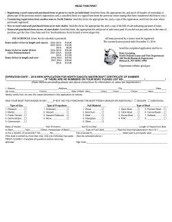
Step
Hose Assembly
Fig I
>
8.1
8.2
8.3
Control Unit
Step
9.1
Fig. I
9.2
Launching the Hoist
Step
10.1
10.2
10.3
Procedure
The hose is shipped in one coil of 75 feet, and must be cut to proper lengths. It is
important that the hoses connecting to the front of the tanks be of equal length, and
the hoses connecting to the rear of the tanks be of equal length. Cut the hose as
follows:
Cut the 75’ hose in half - forming two pieces 37-1/2 feet long.
Using one 37-1/2’ hose, connect one end to the Tank Nipple at the front of the tank.
Route the opposite end of the hose through the support gusset of the Upper Tank Band
(inset fig. I) and attach it to the 90 degree Elbow at the rear section of the tank.
Secure each hose end with a Hose Clamp. Stretch the hose loop as far in front of the
tanks as possible, cutting the hose at the end of the loop.
Repeat the above step for the other tank. The result is two front hoses of equal length,
and two rear hoses of equal length, with all hoses meeting at the same point in front of
the hoist.
Procedure
The B-Model hoist is supplied with a 4-valve Control Unit [10]. Each of the four
valves, with its connecting hose, controls the air supply to a corner of the hoist. The
order of hose attachment can be tailored to fit the application, however, the typical
attachment simulates each corner of the Control Unit to the corners of the hoist as
shown in Fig. I. Each potential hoist operator must be familiar with the Control
Unit and the Valve Handle sequence before operating the hoist.
Attach Hoses [9] to the valves in the Control Unit [10] and secure with Hose Clamps .
Procedure
Secure the Control Unit (without housing) to a Hull Support Column [3,4] in the front
of the hoist. Make sure all valves are closed in the ‘Dry-Dock” position. Attach a
towing line to the rear End Channel. Tank Plugs are recommended for all tows.
Back the trailer into the water to float the hoist. Do this SLOWLY so that the front of
the tanks will not pivot hard into the trailer.
Slowly tow the hoist to its mooring location.
End of Sec. 3
Installation
HydroHoist International, Inc.
Model: 4500B
Publication: 8/01/04
Selecting Position for
Boat & Hoist
Step
1.1
Fig. F1
1.2
1.3
1.4
1.5
Installation
Sec. 4 Pg. 1
Procedure
Pull the boat into the boat slip so that the bow can be easily reached from the front of
the slip. Allow at least 12 inches of space between the dock and the boat, at the dock
level, in the event the boat may need to be later moved in final positioning.
With the boat in the desired location, place a mark on the dock where the boat’s
transom is positioned. Note: Do not include extensions to the hull such as swim
platforms; the transom mark should reflect the location of the end of the bottom of the
hull.
Remove the boat and pull the hoist into the slip.
Position the hoist along side the dock and align the rear end of the Hull Support Pads
with the transom mark on the dock.
With the hoist held stationary at this position, place marks on the dock at the location
of the Rear Mooring Assembly and the Front Mooring Assembly.
Fig. F1
Mooring the Hoist
Step
2.1
Fig. F1
2.2
Fig. G1
Procedure
Move the hoist into position and align the rear Mooring Assembly [12] with the mark
on the dock.
Place the Mooring Cover [14] over the Mooring Assembly [12] and the Slider [15]
over the Mooring Cover [14]. Securely attach the Slider [15] of each Mooring Assembly to the dock. This may be done with a suitable rope of 3/4” diameter (max.). The
tab on the Slider should be positioned away from the dock.
POSITION TAB
TOWARDS HOIST
AND TIE FIRMLY
TO THE DOCK.
15
14
Fig. G1
12
HydroHoist International, Inc.
Model: 4500B
Publication: 8/1/04
Installation
Sec. 4 Pg. 2
Step
Final Details
TIGHTEN ALL BOLTS.
3.2
REMOVE ALL TANK PLUGS IF USED.
3.3
Attach the Control Unit frame to the dock in the desired location and install the Control Unit
Housing onto the frame.
Connect the power cord to proper power source and test the motor switch to ensure operation.
3.4
3.5
Fully Raised Position
Lowering the Hoist
Stern Lowered Position
Fully Lowered Position
Step
Procedure
4.1
Rotate the Control Unit Handles operating the valves leading to the REAR sections of the tanks
to the Lift/Launch position . When the air is fully exhausted from the rear section of the tanks,
the stern section of the hoist is suspended from the Floating Walkways.
With the hoist in the Stern Lowered Position (Fig. H1) Rotate the Control Unit Handles
operating the valves leading to the FRONT sections of the tanks to the Lift/Launch position.
With the air fully exhausted from both the front and rear sections of the tanks, the entire hoist is
suspended from the Floating Walkways.
4.2
Step
Procedure
5.1
Pull the boat over the hoist and align the boat’s transom with the transom mark on the dock.
This should properly position the transom just above the end of the Hull Support Pads.
Hold the boat in position at the transom mark and center it side to side over the hoist.
Temporarily tie the loose ends of the Guide Ropes to the REAR cleats of the boat to hold the
boat in position for the initial lifting steps.
Continue to hold the front of the boat centered over the hoist, pushing the boat to stern gently
until the Guide Ropes are taut. The Guide Ropes center the boat’s stern over the hoist and keep
the transom aligned with the rear of the Hull Pads.
Procedure
5.2
5.3
Lifting the Boat
Temporarily secure one end of each guide rope to the outboard end of each front Upper Tank
Band. Extend each rope to the rear of the hoist and drape it over the Walkway for use later.
Fig. H1
Fig. H1
Positioning the Boat
Procedure
3.1
Step
6.1
6.2
6.3
6.4
Continue holding the boat in position as described in the above stepRotate the Control Unit Handles operating the valves leading to the FRONT sections of the
tanks to the Lift/Launch position and turn the Power Switch to the ON position.
Note: It may be necessary to reset the GFCI switch to activate the switch.
When the hoist contacts the boat hull and the boat is no longer floating freely, you may
discontinue pushing back on the boat. As the FRONT of the hoist and boat rise, observe the
centering position of the boat on the Hull Support Pads - if not centered correctly, lower the
hoist and realign the boat or pads as necessary.
Continue raising the FRONT of the hoist until air bubbles from under the FRONT of the tanks,
then...
Rotate the Control Unit Handles operating the valves leading to the REAR sections of the tanks
to the Lift / Launch position, and...
rotate the Handles leading to the FRONT sections of the tanks to the Dry-Dock position.
As the REAR of the hoist and boat rise, observe the centering position of the boat on the Hull
Support Pads - if not centered correctly, lower the hoist and realign the boat or pads as
necessary.
6.5
Continue raising the REAR of the hoist until air bubbles from under the REAR sections of the
tanks, then again...
rotate the Control Handles operating the valves leading to the FRONT sections of the tanks to
the Lift / Launch position to continue filling the FRONT sections of the tanks.
6.6
When air bubbles from all sections of all tanks, turn the Power Switch to OFF and rotate ALL
Control Handles to the Dry-Dock position. The hoist should now be fully lifted.
End of Sec. 4
HydroHoist International, Inc.
Model: 4500B
Publication: 8/1/04
Final Adjustments
Sec. 5 Pg. 1
Final Adjustments
Balance and Load
Step
1.1
Procedure
Carefully check the boat’s position on the hoist and Hull Support Pads. The boat
should be centered side to side, with the hull Support Pads contacting the hull
between the chines and to the transom area.
Note 1: It is common for some unavoidable crossing of the chines at the bow of the
boat, which is acceptable.
Note 2: The ends of the Hull Support Pads should extend to the transoms of outboard
boats; for stern-drive boats, the ends of the Hull Support Pads should not extend
forward of the engine compartment. Reposition the boat or pads if necessary.
Guide Ropes
1.2
Carefully check the hoist’s position in the water. The tanks should be level fore to aft
with an acceptable 4-inch drop to stern. Correct the fore to aft position of the boat on
the hoist to rectify any unbalance.
1.3
At least 1/3 of each tank should be above the water surface for correct lifting and
hoist stability. If less than 1/3 of the tank is above the water, the boat is too heavy for
the hoist and a larger hoist should be installed.
Step
2.1
Procedure
With the boat correctly positioned on the hoist, untie both the FRONT and REAR
ends of each Guide rope. Tie a small loop (about 6 inches in diameter) in one end of
each Guide Rope and place the loops over the REAR cleats of the boat.
Pull the Guide Ropes tight and tie the loose ends to the outboard ends of each FRONT
Upper Tank Band. (Right rope to right tank band, left rope to left tank band.)
Attach the Warning Decals (2003400) to the Guide Ropes.
2.2
2.3
Final Inspection
Wrapping Up
Step
3.1
♦
♦
♦
♦
♦
♦
C A U T I O N:
HIGH WINDS
AND
ROUGH WATER
CONDITIONS
Procedure
Operate the hoist again - launch then lift - checking for proper positioning of the boat
and Pads and for proper operation of the lift and Walkways.
Secure a bow line to the boat and to the boat dock.
Confirm that the Operating Instructions are in the Control Unit.
Unplug the power cord and stow it in a secure position.
Complete the Warranty information and apply the adhesive Serial Number Tag to the Top
Plate of the Control Unit.
Close and secure the Control Unit Lid.
Whenever possible, instruct the boat owner in the proper operating procedures of the hoist.
The HydroHoist Mooring Apparatus is not designed for severe wind or
water conditions. Should the potential for severe conditions exist, it is
recommended that mooring lines be secured from dock structure to bow
and stern of craft to prevent damage to the HydroHoist Mooring
Apparatus.
End of Sec. 5
Trouble Shooting
Sec. 6 Pg. 1
HydroHoist International, Inc.
Model: 4500B
Publication: 8/1/04
Trouble Shooting
CONDITION:
CAUSE:
CORRECTION:
CONDITION:
Hoist will not completely lift boat from water or stern remains low.
A. Boat loaded too far to rear.
B. Water or equipment in boat creating additional weight.
C. Boat weight exceeds lifting capacity of hoist.
A. Reposition boat forward to balance weight over hoist and adjust the Guide Ropes to
maintain proper positioning.
B. Remove water or equipment.
C. Install correct size hoist to accommodate the boat’s true weight.
A
Hoist tips side to side when lifting or launching.
CAUSE:
A.
B.
C.
D.
Restricted air flow to one quadrant of the lifting tanks.
Hoses not of equal length.
Bulkhead inside of tank is broken or leaking
Host is not square, frame is twisted.
CORRECTION:
A.
B.
C.
D.
Remove kinks or water-lock from hoses.
Correct hose length.
Replace tank.
Loosen Tank Bands, level hoist, and properly tighten Tank Bands.
CONDITION:
CAUSE:
CORRECTION:
CONDITION:
CAUSE:
CORRECTION:
CONDITION:
CAUSE:
CORRECTION:
Walkways unstable when walked upon.
A. Brace system not functioning properly.
A. Repair or replace.
Hoist leans down on one corner.
A. Leak in valve, tank, or hose for that quadrant.
A.
Locate leak and repair.
Hoist leans down on one side (not just one corner).
A. Leak in fore and aft quadrant - tank to valve or bulkhead leaking.
A.
Locate leak and repair. Replace tank if bulkhead damaged.
End of Sec. 6
Parts List
Sec. 7 Pg. 1
HydroHoist International, Inc.
Model: 4500B
Publication: 8/1/03
Parts List
STEEL ON BOTTOM
ITEM #
PART #
DESCRIPTION
QTY
1
2810000
WALKWAY - BLUE - 10FT
4
2
3031700
BRACE - HULL PAD - 25 3/4 ANGLE
2
3
3033000
COLUMN - HULL SUPT - 36 ANGLE - LH
2
4
3033001
COLUMN - HULL SUPT - 36 ANGLE - RH
2
5
3050640
CHANNEL - END - 3" X 9'11"
2
6
3055000
VERT ADPT - STANDARD H MODEL
4
7
3056300
STRAP - 14 STEEL TIE
4
8
3056400
SPANNER - KEEL - 31 1/2 ANGLE
6
9
3072502
HOSE - 1 ID CUT 75' LONG
1
10
3550026
CNTRL - 4V - 1M 120V PLAST. MAN.
1
11
4021155
GUIDE - CENTERING - 6' UNIV. (OPT.)
4
12
4043210
MOORING ASSY - B-MODEL
2
13
4050100
TANK BAND - 24 UPPER
8
14
4666160
COVER - MOORING ASSY - 45/75 B
2
15
4669165
SLIDER - PE - EURO MOORING
2
16
4812025
HINE GRIP - WALKWAY
8
17
4812030
BRACE - WALKWAY
4
18
4812060
HINGE ASSY - WALKWAY
4
19
4812070
PIN - HINGE 10 1/2
8
20
4812080
HINGE BASE ASSY
4
21
5010310
TANK - 24" X 23' - B - NEW
2
22
5025102
PAD - VEE BRACKET
1
23
5025600
PAD - HULL - REGULAR 14'
2
24
5201901
COVER - 6' CENTERING GUIDE(OPT.)
4
25
6098000
PARTS BAG - LIFT - 4500 b
1
26
6937100
PARTS BAG - WALKWAY 45/75/9B4T
1
27
6937400
PARTS BAG - CABLE ASSY 45/75 B
1
28
6939000
PARTS BAG - MOORING - B303
1
Parts List
Sec. 7 Pg. 2
HydroHoist International, Inc.
Model: 4500B
Publication: 8/1/03
Parts List
STEEL ON TOP
ITEM #
PART #
DESCRIPTION
QTY
1
2810000
WALKWAY - BLUE - 10FT
4
2
3031700
BRACE - HULL PAD - 25 3/4 ANGLE
2
3B
4031100
COLUMN - HULL SUPT - UNIV - NORM
2
4B
4031110
COLUMN - HULL SUPT - UNIV - OPP
2
5B
3050610
CHANNEL - END - 3" X 7' 11"
2
5B
3060650
CHANNEL - END - 3" X 11'11"
2
6
3055000
VERT ADPT - STANDARD H MODEL
2
9
3072502
HOSE - 1 ID CUT 75' LONG
1
10
3550026
CNTRL - 4V - 1M 120V PLAST. MAN.
1
11
4021155
GUIDE - CENTERING - 6' UNIV. (OPT.)
4
12
4043210
MOORING ASSY - B-MODEL
2
13
4050100
TANK BAND - 24 UPPER
8
14
4666160
COVER - MOORING ASSY - 45/75 B
2
15
4669165
SLIDER - PE - EURO MOORING
2
16
4812025
HINE GRIP - WALKWAY
8
17
4812030
BRACE - WALKWAY
4
18
4812060
HINGE ASSY - WALKWAY
4
19
4812070
PIN - HINGE 10 1/2
8
20
4812080
HINGE BASE ASSY
4
21
5010310
TANK - 24" X 23' - B - NEW
2
22
5025102
PAD - VEE BRACKET
1
23
5025600
PAD - HULL - REGULAR 14'
2
24
5201901
COVER - 6' CENTERING GUIDE (OPT.)
4
25
6098000
PARTS BAG - LIFT - 4500 b
1
26
6937100
PARTS BAG - WALKWAY 45/75/9B4T
1
27
6937400
PARTS BAG - CABLE ASSY 45/75 B
1
28
6939000
PARTS BAG - MOORING - B303
1
End of Sec.7
HydroHoist International, Inc.
Model: 4500B
Publication: 08/01/03
Assembly
Sec. 8 Pg. 1
Technical Supplement
NOTE: The optional Centering Guides take off approximately 5” of width total.
™


© Copyright 2026