
Installation and Parts & Service Manual ROTO – 180
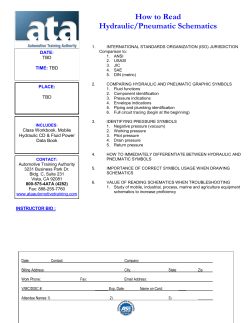
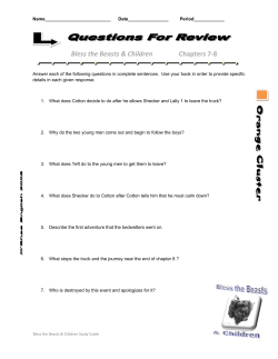
DIVERSIFIED METAL FABRICATORS, INC. Installation and Parts & Service Manual ROTO – 180 (Short – Standard – Long) June 2014 SERIAL NUMBER ________________________ NOTE: Please refer to the serial numbers when ordering parts or inquiring about warranty items. DMF 665 Pylant Street Atlanta, Georgia 30306 Parts (404) 607-1684 Parts Fax (404) 879-7888 [email protected] Service Department (404) 879-7882 [email protected] Phone (404) 875-1512 Fax (404) 875-4835 [email protected] http://www.dmfatlanta.com DIVERSIFIED METAL FABRICATORS, INC. ROTO - 180 Message from DMF Thank you for choosing DMF ROTO-180. We make every effort to provide quality, safe and rugged products for the railroad. We hope you'll find our product to be satisfactory in every way. We take product support very seriously, so if you have any questions, please contact us. Manuals, service bulletins and general information are available on our website listed below. Contact: Diversified Metal Fabricators 665 Pylant St. NE Atlanta, GA 30306 (404) 875-1512 (404) 875-4835 Fax (404) 607-1684 Parts http://www.dmfatlanta.com [email protected] Ship to: 668 Drewry St. NE Atlanta, GA 30306 © 2014 DMF, Inc. All Rights Reserved. DIVERSIFIED METAL FABRICATORS, INC. ROTO-180 TABLE OF CONTENTS Table of Contents ........................................................................................................ 1 Set-Up ......................................................................................................................... 2 I. II. Pre-Installation ................................................................................................... 2 Initial Instructions ............................................................................................... 2 1.0 Control Panel Installation...................................................................................... 4 2.0 Subframe Mounting Procedure .............................................................................. 5 3.0 ROTO-180 System Connection ............................................................................... 6 4.0 Operation & Troubleshooting ................................................................................ 7 4.1 Operation .......................................................................................................... 7 4.2 Troubleshooting .................................................................................................. 7 5.0 Operating the ROTO 180 System ........................................................................... 8 5.1 5.2 5.3 5.4 5.5 Enabling the ROTO 180 System ............................................................................. 8 Raising the Body ................................................................................................. 8 Lowering the Body .............................................................................................. 8 Swinging the Body .............................................................................................. 8 Disabling the ROTO 180 System ............................................................................ 8 6.0 Operation of the Power Take-Off (PTO)................................................................. 9 6.1 Engine Driven Hydraulic Pump .............................................................................. 9 6.2 Transmission Driven PTO and Pump ....................................................................... 9 7.0 Operating the Raildogs ........................................................................................ 11 7.1 Hydraulic Raildogs ............................................................................................. 11 7.2 Manual Raildogs ................................................................................................ 11 8.0 Engaging the Rail ................................................................................................ 12 8.1 Getting On the Rail ............................................................................................ 12 8.2 Getting Off the Rail............................................................................................ 12 9.0 Maintenance Instructions .................................................................................... 14 9.1 Inspection and Maintenance ............................................................................... 14 9.2 Lubrication Specification..................................................................................... 14 10.0 ROTO-180 Schematics & Assemblies ................................................................. 15 DMF Limited Warranty Policy .................................................................................... 61 1 © 2014 DMF, Inc. All Rights Reserved. DIVERSIFIED METAL FABRICATORS, INC. ROTO-180 SET-UP I. Pre-Installation NOTE: Read all instructions and check that all required kit parts are included before beginning the installation. The proper installation of this equipment is solely the responsibility of you, the authorized installer. When in doubt, contact DMF for assistance. Tools Required for Installation: • • • Welder (Arc or Mig) Hoist or Overhead Crane Frame Drill (with 5/8” Drill Bit) • • • General Mechanic Tools Cutting Torch Hand Grinder Assembly Drawings for Parts Procurement: Title Standard ROTO 180 Assembly Standard ROTO 180 Electric Schematic Standard ROTO 180 Hydraulic Schematic Manifold Valve Assembly General Arrangement-Ref. Only Drawing # 18000 18900 18901 18905 ROTO-180 Qty. 1 1 1 1 1 Additional Material that may be Required: Item Hydraulic Hose (Appropriate Size & Rating for System) Swivel Hose Ends (Appropriate Size & Rating for System) Hydraulic Oil – Unax RX-46 (or Equivalent) Grease – Quaker State Multipurpose Lithium EP#2 Bolts – 5/8”-11 Gr.5 (for Subframe Attachment) Nylock Nuts – 5/8”-11 Gr.5 (for Subframe Attachment) II. As As As As Qty. Required Required Required Required 12 12 Initial Instructions Work Area: The area in which the ROTO-180 installation is to occur should meet minimum requirements in order to facilitate the process and provide adequate conditions in which the work can be completed safely, accurately and in a timely manner. • • • Floor - The floor should be level in order to provide a good surface for the installation and alignment of the subframe. Lighting - The work area should be adequately lighted. Space - There should be enough space to maneuver the subframe and truck body components into position and to safely work around other equipment. Preliminary Truck Preparation: The truck should be outfitted with a hydraulic system that includes a 30 gallon tank, suction filter, pump, PTO (Power Take-Off), relief valve and a power beyond/ diverter valve for the railgear (if equipped). The pump should be capable of 21 GPM at 2000 PSI. See section 6 for enabling and operation of the PTO. 2 © 2014 DMF, Inc. All Rights Reserved. DIVERSIFIED METAL FABRICATORS, INC. ROTO-180 NOTE: Frame modifications, other than that required for mounting the ROTO-180, must adhere to the truck manufacturers recommended standard practice. NOTE: Your ROTO-180 kit has been tested and pre-wired at the factory to aid in the installation process. The installation consists of three simple steps: Control Panel Installation, Subframe Mounting and System Connection 3 © 2014 DMF, Inc. All Rights Reserved. DIVERSIFIED METAL FABRICATORS, INC. ROTO-180 1.0 CONTROL PANEL INSTALLATION In your kit is a switch panel wired with a 16-10 cable, approximately 18 ft. long. Find a suitable hole in the truck firewall (on driver’s side) to feed the cable through from the inside of the cab. Mount the control panel in a convenient location for the operator. A commonly used location is at the lower left hand corner of the windshield on top of the dash. Make certain that the 16-10 cable will not interfere with any pedals or controls. Connect the fused wire (marked “power”) to the battery tap on the vehicle fuse panel. Connect the indicator lamp ground (“ground”) to a good location under the dash. Connect the truck body clearance light wire (“cl. Light”) to either the truck clearance light switch or the parking light tap on the headlight switch. 4 © 2014 DMF, Inc. All Rights Reserved. DIVERSIFIED METAL FABRICATORS, INC. ROTO-180 2.0 SUBFRAME MOUNTING PROCEDURE The ROTO-180 should be installed on the chassis with the center of the swing bearing located 3” forward of the center of the tandem (or a single axle rear) to provide maximum support while swinging. If your kit is a standard 10/12- yard size, your chassis must have a minimum cab to tandem (or C.A.) of 87” to mount the unit at the above location. The 3” shift forward allows better weight transfer to the front axle. For “long” ROTO’s with 12/14 -yard bodies, the center of the swing bearing is to be located 15” forward of the center of tandem. The minimum C.T. is 111”. The subframe (located under the swing bearing) is bolted to the vehicle frame with four mounting angles (near the center of rotation) and four offset flat bar clips. Set the ROTO package on the chassis at the pre-determined location and match drill through the mounting angles and chassis frame. Secure the subframe to the truck chassis with 5/8” Grade 5 bolts. NOTE: The slotted leg of the mounting angle bolts to the exposed leg of the mating subframe angle. The slot accommodates different chassis frame widths. Locate two of the offset flat bar clips at the extreme front end of the subframe and match drill through the frame. Bolt the clips to the chassis frame as with the angles. Then, weld the clips to the ROTO subframe. Similarly, locate the other two flat bar clips near the rear end of the subframe and attach as described above. NOTE: If the truck is outfitted with railgear and the subframe extends over the railgear mounting bracket, move the rear two flat bar clips to ½” forward of the frame bracket. Do not weld clips to the railgear bracket. 5 © 2014 DMF, Inc. All Rights Reserved. DIVERSIFIED METAL FABRICATORS, INC. ROTO-180 3.0 ROTO-180 SYSTEM CONNECTION See Truck Preparation in section II for PTO and hydraulic system requirements. Under the front center of the swing bearing plate are three #12 JIC hydraulic fittings. Connect the driver’s side fitting to the pressure line from the pump. The curbside fittings are the return to the tank. These must be dedicated returns. (Ref. Dwg. #18901, Hydraulic Schematic) Pull the 16-10 cable down the driver’s side of the frame to the driver’s front corner of the subframe. Use ty-straps to secure the cable and hoses. Welded to the front cross tube of the lower subframe is a covered terminal strip. Connect the 16-10 cable at the terminal strip using the wire color codes. (Ref. Dwg. #18900, Electrical Schematic.) 6 © 2014 DMF, Inc. All Rights Reserved. DIVERSIFIED METAL FABRICATORS, INC. ROTO-180 4.0 OPERATION & TROUBLESHOOTING 4.1 Operation Engage the PTO and, if equipped, shift the diverter valve to activate the ROTO-180. On the control panel in the cab, hold the hoist switch in the raise position. Raise the body a few inches to clear the body lock. Activate the swing switch and rotate the body a few times in both directions to purge the air out of the swing cylinders. For overall operation of the ROTO-180 see below. 4.2 Troubleshooting If after depressing the ‘Hoist Down’ switch, the red indicator lamp doesn’t glow, there is either an improper ground, a bad power fuse, or no power to the fuse. If during operation of the ROTO, you get an opposite result than indicated by the control panel, you can switch wires in the cab or on the valve terminals in the enclosure under the dump body. If the body swings too fast, flow controls are located in the upper sub frame on the back side of the valve manifold. Turning the adjuster knob clockwise will restrict fluid flow and slow down the swing speed. REMEMBER: The ROTO will not swing until the body is raised to clear the body lock. NOTE: Rail operation of the ROTO-180 requires the use of either manual or hydraulic raildogs to stabilize the truck. For application of raildogs, please refer to the separate “Raildog Installation” manual. 7 © 2014 DMF, Inc. All Rights Reserved. DIVERSIFIED METAL FABRICATORS, INC. ROTO-180 5.0 OPERATING THE ROTO 180 SYSTEM 5.1 Enabling the ROTO 180 System (1) Engage PTO as outlined previously. An illuminated red light will indicate engagement. (2) If truck is equipped with selector valve, shift to activate ROTO 180. 5.2 Raising the Body (1) Hold the hoist switch in the “Hoist Raise” position. The body will stop at 45 °. NOTE: The ROTO 180 is equipped with an automatic tailgate release. This feature is activated when the body raises 22-1/2 °. To override the automatic release, hold “Tailgate Override Switch” simultaneously with “Hoist Raise Switch”. The body will continue to raise with the tailgate locked. The override, however, defeats the 45 ° stop when engaged. Do not exceed 45°. (2) The tailgate may be operated, at any time, by switching “Tailgate” to “Release”. 5.3 Lowering the Body (1) Switch hoist to “Hoist lower”. The switch will stay in this position. A red LED will light up. (2) Lock the tailgate by switching “Tailgate” to “Latch”. (3) After the body has lowered, switch “Hoist” to its neutral position. The red LED will turn off. 5.4 Swinging the Body (1) Raise the body to clear body lock. Then activate “Swing” switch in desired direction. NOTE: When swinging the body, operator judgment determines the use of the tailgate “Release” or “Override” modes. The same holds true if truck is equipped with “Rail dogs”, to avoid overturning or derailing. (2) After dumping, with body down, center the body and check engagement of the body lock. 5.5 Disabling the ROTO 180 System (1) Disengage PTO as outlined in section 6.0. Illuminated red light will turn off. (2) Do not drive with the “Switch Enable” or any other switches in the on position. Make sure they are in the off or neutral position. 8 © 2014 DMF, Inc. All Rights Reserved. DIVERSIFIED METAL FABRICATORS, INC. ROTO-180 6.0 OPERATION OF THE POWER TAKE-OFF (PTO) 6.1 Engine Driven Hydraulic Pump The truck may be equipped with an engine driven hydraulic pump, located directly behind the front bumper. The pump is driven through a drive shaft connected to the front of the engine. To prevent unnecessary wear & tear, the hydraulic pump is unloaded when the ROTO electrical system is disabled. (This does not create any pressure and very little flow.) ****WARNING**** The pump can turn at any time the truck motor is operating. Stay clear of the pump drive shaft at all times. To Enable and Disable the Hydraulic and Electrical System: (1) The “System Enable Switch”, is a push / pull switch that is located in the cab, at the middle of the instrument panel. A red light indicates that the system is on or off. This switch must be on whenever you want to operate the hydraulic system. (2) PULL out the switch, to enable the system. The red light will come on to indicate operation. (3) PUSH in the switch, to disable the system. The red light will go out to indicate end of task. To Enable the System: (1) Engage PTO as outlined above. An illuminated red light will indicate engagement. (2) If truck is equipped with selector valve, shift to activate ROTO. Comments on the Hydraulic System: The system is configured to provide up to (25) gallons per minute (GPM) flow. When the engine speed makes the pump turn fast enough to exceed this setting, the hydraulic system will automatically unload. To reset the unloading valve and restore system operation, lower the engine speed to an idle. The unloading valve will then automatically reset and allow normal system operation. The system is configured to continuously unload the pump whenever the “System Enable” switch is off. This allows the truck to be driven on the road without the parasitic drag of the pump. The pump will turn with the engine, but will not be allowed to build hydraulic pressure. 6.2 Transmission Driven PTO and Pump The truck may be equipped with a transmission driven PTO and pump. ****WARNING**** PTO should be engaged only with the truck stopped. Do not drive truck with PTO engaged: transmission, pump and PTO damage may occur. Manual Transmission (1) A PTO is, and should be, operated as an integral part of the main transmission. (2) Before shifting the PTO into or out of gear, disengage the clutch and wait for transmission and/or PTO gears to stop grinding. Automatic Transmission (1) Manual Shift PTO’s (Includes Air Shift) With automatic shift transmissions, the gears turn when the transmission is in neutral, 9 © 2014 DMF, Inc. All Rights Reserved. DIVERSIFIED METAL FABRICATORS, INC. ROTO-180 therefore, the gear clashing will occur if the power take-off is shifted into gear at this time. • With Converter Driven Gear: a. Shift transmission into any of the drive positions, this will stop the gears from turning. b. Shift PTO into gear. c. Shift transmission into neutral, this will start the gears turning. • With Engine Driven Gear: Shift PTO into gear before starting engine, this will eliminate gear clash. (2) Power Shift PTO’s • Engage PTO with the Engine at Idle Speed. 10 © 2014 DMF, Inc. All Rights Reserved. DIVERSIFIED METAL FABRICATORS, INC. ROTO-180 7.0 OPERATING THE RAILDOGS 7.1 Hydraulic Raildogs (1) (2) (3) (4) Check and make sure that the truck’s parking brake is on. Engage the PTO or turn on system enable switch. Remove the safety pin-off pins. With the raildog clamps open, lower the clamp assembly to the rail position using the manual valve. (5) Close the raildog clamps. The top of the inner jaw should be approximately ¼” below the lower edge of the railhead. If not, check the truck tire pressure. Improper inflation could affect clamp height setting and proper engagement of the raildogs. (6) Visually check that both raildogs have clamped onto the rail securely. (7) Perform work function. • To stow the raildogs, reverse the above procedure. Replace the safety pin-off pins. 7.2 Manual Raildogs (1) Remove raildogs from hook on mounting bracket. (2) Swing down into position, move collar up and the spread clamps will clear rail. (3) Move collar down and the clamps will close. The top of the inner jaw should be approximately ¼” below the edge of the railhead. If not, check the truck tire pressure. Improper inflation could affect clamp height setting and proper engagement of the raildogs. (4) Tighten set screw to lock collar. (5) Perform work function. • • To remove the raildogs, unlock collar (if equipped) move collar up and swing the raildog either fore or aft to clear the railhead. To stow the raildogs, swing the raildog out and up and hook the ring on the collar to the hook on the mounting bracket. 11 © 2014 DMF, Inc. All Rights Reserved. DIVERSIFIED METAL FABRICATORS, INC. ROTO-180 8.0 ENGAGING THE RAIL 8.1 Getting On the Rail Lower rear guide-wheels first: (1) (2) (3) (4) (5) (6) (7) At the track crossing, drive past the track, then back the vehicle onto the rails. Engage the truck’s parking brake to prevent the truck from rolling. If the railgear has brakes, turn brake switch on. Engage the PTO or 12Volt electrical hydraulic pump. Remove the safety pin-off pins (one each side). Push / Pull valve handle to lower wheels to engage rail. When both wheels are fully down and properly engaging rail, replace safety pin-off pins. NOTE: Rear end can be articulated to facilitate alignment by operating one valve at a time. Lower front guide-wheels: (1) (2) (3) (4) If necessary drive the truck into position to line up the front guide-wheels with the rail. Engage the PTO or turn on system enable switch. Remove the safety pin-off pins (one each side) and stow in provided storage tubes. Check and make sure that the front guide-wheels line up with the rail, then engage wheels. NOTE: The front guide-wheel assembly is an over-center design and does not require safety pin-off pins engaged in the rail mode. On the tracks: (1) Do not exceed 30 MPH while on the track. All railroad speed rules should be observed. (2) Be aware that some high rail gear is insulated, and will not operate the crossing gate circuits. (3) Reduce speed at all crossings, curves, branch lines, switches and frogs. (4) Traction is reduced on the track. Tire damage may result from spinning wheels on track. (5) Braking distance is increased on the track. Do not slide tires or guide-wheels on the tracks. (6) Do not exceed the maximum rated capacity of the equipment. (7) On newer trucks with Anti-Lock braking systems, the amber ‘ABS’ dash light may remain on with the front wheels elevated. This will not effect rear truck braking or rail wheel braking. 8.2 Getting Off the Rail Removing truck from track: (1) (2) (3) (4) (5) (6) (7) Engage the PTO and the truck parking brakes. Leave the truck running and the transmission in neutral gear. Lift both sets of railgear (there is no preference for removal order. Engage the safety pin-off pins in highway position. Disengage the switch that controls the railgear brakes (if applicable). Disengage the PTO or de-activate system enable switch before moving the truck. If the amber ‘ABS’ dash light remains on during rail operation, the truck engine must be turned off and restarted after returning to highway operation. This will clear the ‘ABS’ after a few seconds. If the amber light remains on during road operation, the truck’s 12 © 2014 DMF, Inc. All Rights Reserved. DIVERSIFIED METAL FABRICATORS, INC. ROTO-180 brake system may have an active fault and should be checked out. Please refer to the truck’s operation manual. 13 © 2014 DMF, Inc. All Rights Reserved. DIVERSIFIED METAL FABRICATORS, INC. ROTO-180 9.0 MAINTENANCE INSTRUCTIONS 9.1 Inspection and Maintenance Daily: • • • • Visually inspect for hydraulic fluid leaks. Check and make sure that all threaded fasteners are secured. NOTE: All hex nuts are either nylon insert or slotted hex nuts with cotter pins. Check and make sure all tie straps that secure hoses from moving parts and exhaust systems are in place. Replace if cracked or worn. Inspect wheel flanges for excessive wear, primarily noting difference in wear between wheels on the same axle or diagonally. If abnormal pattern is noted, check railgear alignment (see alignment procedure). Weekly: • • Visually inspect the raildog clamps for wear and proper engagement of railhead. Grease and lubricate all grease fittings on front and rear railgear and guidewheel assemblies. NOTE: There are six (6) locations on front assemblies and fourteen (14) locations on rear assemblies. • • • • Grease raildog fittings on pivot tube of slide bracket and head & base ends of clamp cylinder. Grease ROTO fittings according to locations in Drawing: ROTO Grease Fitting Locations in section 10.0. Check level of hydraulic oil and all other fluids. Check air pressure in tires and inflate to proper inflation pressure (if necessary). Bi-annually: • • • • • Remove the hubcaps from the railwheels and inspect for deterioration or loss of wheel bearing grease. Unless there is a problem, the cavity may be topped off with the recommended grease without removing and/or re-packing the bearings. Clean the hubcap and mating surfaces and apply a bead of silicone gasket and re-attach securely. Clean the strainer /filter in the hydraulic power unit tank. Inspect wheel flanges for excessive wear. If abnormal pattern is noted, check railgear alignment (see alignment procedure). Rail test for proper traction and braking. If abnormal, adjust properly (see traction procedure). Annually: • • Inspect all pins and rail clamps for excessive wear and replace as necessary. Service hydraulic system per manual, which includes replacing oil filter element. 9.2 • • • • Lubrication Specification Grease fittings: Quaker State Multipurpose Lithium EP #2 (or equal) Hydraulic oil: Unax RX-46 hydraulic oil (or equal) Wheel bearings: Quaker State Multipurpose Lithium EP #2 (or equal) Oil filter element: Gresen K-23019 14 © 2014 DMF, Inc. All Rights Reserved. DIVERSIFIED METAL FABRICATORS, INC. ROTO-180 10.0 ROTO-180 SCHEMATICS & ASSEMBLIES 10.1 Installation Drawings 10.1.1 M180100 Roto Chassis Requirements 10.1.2 R870010A Truck and ROTO Dump Body with Standard Equipment 10.1.3 R870010B Truck and ROTO Dump Body with Optional Equipment 10.1.4 R18512 ROTO Grease Fitting Locations 10.1.5 R17000 ROTO Assembly Sub-Frame (Short) 10.1.6 R18000 ROTO Assembly Sub-Frame (Standard) 10.1.7 R19000 ROTO Assembly Sub-Frame (Long) 10.1.8 18269 Center Lock Assembly 10.1.9 R18284 Dump Body Limit Prop 10.2 Electrical System 10.2.1 18900 Standard ROTO Electric Schematic 10.2.2 R20188 Remote Control with Full Time Hydraulics Electrical Schematic (POST 1995) 10.2.3 20756 Electrical Schematic with 3 Proximity Switches 10.2.4 20794 2014 N/S SPEC ROTO with Diamond Logic 10.2.5 20771 ROTO Electrical Schematic, Subframe with 3 Proximity Switches & 30 Degree Swing Alarm 10.2.6 20769 Limit Switch Kit for ROTO 10.2.7 20754 Proximity Switch Kit for ROTO 10.2.8 R20114 ROTO Pendant Box Assembly 10.2.9 R20115 ROTO Switch Box Assembly, In-Cab 10.3 Hydraulic System 10.3.1 240316 Hydraulic Cylinder Assembly, ROTO Swing, Right Hand Side 10.3.2 240315 Hydraulic Cylinder Assembly, ROTO Swing, Left Hand Side 10.3.3 18280 ROTO Tailgate Cylinder 10.3.4 R18901A ROTO with Manifold Hydraulic Schematic (1994 & 1995) 10.3.5 R18901B ROTO with Manifold Hydraulic Schematic (1996 & 1999.5) 10.3.6 R18905A Manifold Valve Assembly (Vickers) 10.3.7 R18901 ROTO with Manifold Hydraulic Schematic (Parker) 10.3.8 18905 Manifold Valve Assembly (Parker) 10.3.9 18941 Standard ROTO Hydraulic Schematic 10.3.10 18925 12’ Standard ROTO Subframe with Hydraforce Manifold 15 © 2014 DMF, Inc. All Rights Reserved. DIVERSIFIED METAL FABRICATORS, INC. ROTO-180 10.3.11 18923 14’ Standard ROTO Subframe with Hydraforce Manifold 10.3.12 18926 Manifold Valve Assembly (Hydraforce) 10.3.13 R20183 Front Mount/Full Time Pump Hydraulic Schematic 10.3.14 R20186 Hydraulic Hose Chart (POST 1995) 10.3.15 R20184 Bill of Materials for Hydraulic Schematic (POST 1995) 10.3.16 20301 2014 N/S SPEC ROTO Chassis Hydraulic Schematic 10.3.17 20279 HOC Hydraulic Schematic 10.4 ROTO Options 10.4.1 R20000A Beacon Lights, Hydraulic Tanks, Fuel Tanks, Tank Steps 10.4.2 R20000B Spare Tire Carrier, Fenders, Apron, Spreader Chutes 10.4.3 R20185 ROTO Vibrator Kit (POST 1995) 10.4.4 R20230A Trailer Hitch Assembly, Telescoping Hitch Assembly 16 © 2014 DMF, Inc. All Rights Reserved. G ITEM NO. 1 2 3 4 5 6 PART NUMBER 18275 18276 500691 113014 18281 18288 QTY. 1 1 1 1 1 1 DESCRIPTION ROTO CENTER LOCK SPRING (JONES #31) HEX HEAD CAP SCREW, 1/2-13 X 4 FLAT WASHER, 1/2", GR8 LOCKNUT, 1/2-13, GR8 PIN DETAIL, CENTER LOCK ROTO CENTER LOCK WELDMENT 34.5 A 1 17.25 TO SUIT BODY 6 2 3 4 5 A SECTION A-A G 10/4/2012 REDRAWN IN SOLIDWORKS, 500691 WAS 18277, 113014 WAS 18278 JDI REV DATE DESCRIPTION BY TOLERANCES: TITLE: (UNLESS SPECIFIED) FRAC, MACH: FRAC, OTHER: .X .XX .XXX DRILL SIZES: ANGULAR: SURF FINISH: THREADS: ± 1/32" ± 1/16" ROTO-180 APP ROTO CENTER LOCK ASSEMBLY ± .063 ± .030 ± .005 + .015 ± 1° 125 MICRO 2A AND 2B BREAK SHARP EDGES ( 0.030 X 45° MAX ) DIVERSIFIED METAL FABRICATORS,INC.(404)875-1512 DRAWN BY: DSD APPD BY: - DATE: 01/25/83 DRAWING NUMBER: 18269 REV: G TITLE: ROTO-180 REV: - LIMIT SWITCH KIT FOR GATE/LIFT DRAWING #: 20769 BY: JDI DATE: 5/7/12 REV: DIVERSIFIED METAL FABRICATORS, INC. (404) 875-1512 DATE: DESCRIPTION: BY: - # Limit Switch Kit for Roto 180 Kit Contents PART # DESCRIPTION LIMIT SWITCH KIT FOR GATE/LIFT ROTO TAILGATE TRIP CAM ROTO LIMIT SWITCH ASSEMBLY W/ ARM ROTO LIMIT SWITCH (A-B 802T-A) ROTO LIMIT SWITCH ARM (A-B 802T-W1) ROTO LIMIT SWITCH (A-B 802T-A) ROTO LIMIT SWITCH MOUNT PLATE ROUND HEAD MACHINE SCREW, 10-24 X 2-1/2 HEX NUT, 10-24 ESNA LOCK NUT, 10-24 ROUND HEAD MACHINE SCREW, 10-32 X 1/2 20769 18279 18650 18651 18652 18651 18653 605027 605028 605029 605030 QTY. EA. 1 1 1 1 1 1 4 4 4 4 Installation 1. Park the truck on a level surface. -2. See drawing 18318 for tailgate cylinder installation and adjustment. 3. Position the limit switch mount plate (18653) on the subframe and the tailgate trip cam (18279) on the tailgate latch rod and weld in place. Refer to Figures 1 through 3 for location details. Note the length of the subframe. The position of the limit switch mount plate (18653) is different for 12 and 14 foot subframes. Refer to Figure 3 and Figure 4. ITEM PART NO. QTYDESCRIPTION 1 2 3 4 5 6 BOTTOM OF BODY 1 1/2" 1 1/4" 8 13/16" TAILGATE TRIP CAM (18279) LONG SILL LIMIT SWITCH MOUNT PLATE (18653) 6 5/16" SUBFRAME Figure 1 – 12 and 14 Foot Limit Switch Mount Plate/Cam Location B -- A - REV © 2012 DMF, Inc. All Rights Reserved. - - DATE DESCRIPTION TOLERANCES: TITLE: Page 112/14 of 3FOOT ROTO LIMIT SWITCH L (UNLE S S S P E CIFIE D) ± 1/32" FRA C, OTHE R: ± 1/16" .X ± .063 FRAC, MACH: .XX .XXX DRILL SIZES: ANGULAR: SURF FINISH: THREADS: - ± .030 ± .005 + .015 ± 1° 125 MICRO 2A AND 2B BREAK SHARP EDG ES ( 0. 030 X 45° M AX ) D IVER SIFIED METAL FABR IC ATOR S,IN C .(404)875-1512 D R AW N BY: JDI APPD BY: D ATE: 4/2/12 D R AW IN G N U MBE - ITEM PART NO. QTYDESCRIPTION -- 1 - - 2 3 4 5 1 1/2" 1 1/4" 6 TAILGATE TRIP CAM (18279) BOTTOM OF BODY A A LONG SILL LIMIT SWITCH MOUNT PLATE (18653) 1" SUBFRAME Figure 2 – 12 Foot Side View Limit-- Switch Mount Plate/Cam Location ITEM PART NO. QTYDESCRIPTION - 1 - 2 3 4 5 6 B -- A - REV - - DATE DESCRIPTION TOLERANCES: ± 1/32" FRA C, OTHE R: ± 1/16" .X ± .063 1 1/2" 1 1/4" FRAC, MACH: .XX .XXX DRILL SIZES: ANGULAR: SURF FINISH: THREADS: TAILGATE TRIP CAM (18279) ± 1° 125 MICRO 2A AND 2B D IVER SIFIED METAL FABR IC ATOR S,IN C .(404)875-1512 D R AW N BY: APPD BY: D ATE: BOTTOM JDI OF BODY D R AW IN G N U MBER : 4/2/12 - BREAK SHARP EDG ES ( 0. 030 X 45° M AX ) A A LONG SILL LIMIT SWITCH MOUNT PLATE (18653) 2 1/4" SUBFRAME Figure 3 – 14 Foot Side View Limit Switch Mount Plate/Cam Location B -- A - REV - - DATE DESCRIPTION TOLERANCES: © 2012 DMF, Inc. All Rights Reserved. FRAC, MACH: ± 1/32" FRA C, OTHE R: ± 1/16" .X ± .063 .XX .XXX DRILL SIZES: ANGULAR: SURF FINISH: THREADS: + .015 BREAK SHARP EDG ES ( 0. 030 X 45° M AX ) APP 14 FOOT ROTO LIMIT SWITCH LAYOUT SIDE VIEW - ± .030 ± .005 ± 1° 125 MICRO 2A AND 2B BY TITLE: (UNLE S S S P E CIFIE D) D IVER SIFIED METAL FABR IC ATOR S,IN C .(404)875-1512 D R AW N BY: JDI APPD BY: APP 12 FOOT ROTO LIMIT SWITCH SIDE VIEW - ± .030 ± .005 + .015 BY TITLE: (UNLE S S S P E CIFIE D) D ATE: 4/2/12 D R AW IN G N U MBER : - Page 2 of 3 R EV: # R EV: # 4. Mount the limit switches to the limit switch mount plate (18653). The limit switch (18650) with the adjustable arm goes on the inside of the mount plate closest to the tailgate trip cam ITEM PART NO. QTYDESCRIPTION 1 -(18279). 2 3 5. Fully release the tailgate. Raise the bed to 22 degrees, using a protractor to indicate the angle 4 5 between the bed and horizontal. Set the limit switch (18650) with the adjustable arm such that 6 the roller at the end of the arm is in contact with the tailgate trip cam (18279) and at an angle that triggers the limit switch (18650). Refer to Figure 4. CAUTION: CHECK THE ADJUSTABLE ARM POSITION PRIOR TO RAISING BED AS IT CAN BE BROKEN IF IMPROPERLY POSITIONED. A A TAILGATE TRIP CAM (18279) BOTTOM OF BODY SUBFRAME LIMIT SWITCH (18650) LONG SILL Figure 4 – Setting Limit Switch 6. Continue raising the bed until the desired fully raised position is reached (typically 40 degrees). Check to make sure the other limit switch (fully raised switch) is activated by the tailgate latch rod with the bed in the fully raised position. If it is not, loosen the bolt on the arm and rotate the arm until it is in a position that will be activated--- by the- tailgate latch rod. REV DATE BY APP 7. Test the system to insure that it is performing properly by raising theDESCRIPTION bed from stowed position and checking that at the 22 degree position the adjustable limit switch is triggered and at the fully raised position (40 degrees) the bed stops rising. B A TOLERANCES: TITLE: (UNLESS SPECIFIED) FRAC, MACH: ± 1/32" FRAC, OTHER: .X ± 1/16" .XX .XXX DRILL SIZES: ANGULAR: SURF FINISH: THREADS: ± .030 ± .005 ± .063 + .015 ± 1° 125 MICRO 2A AND 2B BR EAK SH AR P ED GES ( 0.030 X 45° MAX ) © 2012 DMF, Inc. All Rights Reserved. DIVERSIFIED METAL FABRICATORS,INC.(404)875-1512 DRAWN BY: JDI APPD BY: DATE: DRAWING NUMBER: - REV: LIMIT SWITCH ARM SET # Page 3 of 3 ROTO-180 REV: - TITLE: PROXIMITY SWITCH KIT FOR GATE/LIFT DRAWING #: 20754 BY: JJDI DATE: 5/7/12 DIVERSIFIED METAL FABRICATORS, INC. (404) 875-1512 DESCRIPTION: BY: - DATE: - REV: # Proximity Switch Kit for Roto 180 Kit Contents PART # DESCRIPTION PROXIMITY SWITCH KIT FOR GATE/LIFT PROXIMITY SWITCH (18MM) PROXIMITY BRACKET – FOR 22/40 DEG PROX. SWITCHES ITEM PART NO. QTYDESCRIPTION PROXIMITY DETECTION PLATE FOR 22/40 PROX SWITCHES 1 -PROXIMITY BRACKET FOR GATE LATCH POSITION DETECTION 2 FLAT 3WASHER, 1”, GR5 20754 20256 20751 20752 20753 238112 4 QTY. EA. 3 1 1 1 1 5 6 Installation 1. Park the truck on a level surface. 2. See drawing 18318 for tailgate cylinder installation and adjustment. 3. Weld the proximity detection plate (20752) on to the inside of the passenger side long sill of the dump body. Refer to Figure 1 for proper location of detection plate. LONG SILL PROXIMITY DETECTION PLATE (20752) 22 TAILGATE OPEN PROXIMITY SENSOR (20256) 1/2" SUBFRAME PROXIMITY SENSOR BRACKET 22/40 DEGREE (20751) 10 BED FULLY RAISED PROXIMITY SENSOR (20256) Figure 1 – Proximity Detection Plate Location 4. Weld the proximity bracket for the 22/40 degree proximity switches (20751) onto the sub frame. Refer to Figure 2 for proper location of proximity bracket. - - B - A REV DATE DESCRIPTION TOLERANCES: (UNLESS SPECIFIED) FRAC, MACH: ± 1/32" FRAC, OTHER: .X ± 1/16" .XX .XXX DRILL SIZES: ANGULAR: SURF FINISH: THREADS: ± .030 ± .005 APP - ± .063 + .015 ± 1° 125 MICRO 2A AND 2B BR EAK SH AR P ED GES ( 0.030 X 45° MAX ) © 2012 DMF, Inc. All Rights Reserved. BY TITLE: DIVERSIFIED METAL FABRICATORS,INC.(404)875-1512 DRAWN BY: JDI APPD BY: DATE: DRAWING NUMBER: 4/2/12 - Page 1 of 3 REV: # 5 6 PROXIMITY DETECTION PLATE (20752) 22 TAILGATE OPEN PROXIMITY SENSOR (20256) E PROXIMITY (20256) BED FULLY RAISED PROXIMITY SENSOR (20256) LONG SILL LONG SILL 1/8" PROXIMITY SENSOR BRACKET 22/40 DEGREE (20751) FLUSH WITH BOTTOM OF LONG SILL 1" Figure 2 – Bracket Location for 22/40 Degree Proximity Switches 5. Place the proximity switches (20256) into the proximity bracket (20751) so that there is an approximately 1/8” gap between the switch and the detection plate (20752). Hand tighten the jam nuts to lock each switch into its initial position. Final adjustment of proximity switches will be addressed in later steps. 6. Take the flat washer and cut it in half to be used as a stop washer on the tailgate latch rod. 7. Weld one half of the washer, to the tailgate rod, on the inside of the tailgate rod support bracket on both sides --of the body. This is to keep the rod from moving from side - to side and B A - Refer to Figure causing interference between the tailgate proximity switch and the tailgate cam. REV DATE DESCRIPTION BY APP 3 and Figure 4 for proper washer orientation and location. TITLE: 12/14 FOOT SWITCH of LAYOUT 8. Weld the bracket for the tailgate proximity switch (20753) to thePROX underside the bed. Refer to Figure 5 for the proper bracket location. DIVERSIFIED METAL FABRICATORS,INC.(404)875-1512 -DRAWN BY: DATE: NUMBER: 9. Place the tailgate proximity switch into APPD theBY:tailgate proximity bracketDRAWING so there is anREV: 4/2/12 - Hand tighten # approximately 1/8” gap betweenJDIthe face of the switch and the tailgate cam. the jam nuts to lock the switch into its initial position. Check to make sure the proximity switch is located over the tailgate cam when the tailgate is un-latched. TOLERANCES: (UNLESS SPECIFIED) FRAC, MACH: ± 1/32" FRAC, OTHER: .X ± 1/16" .XX .XXX DRILL SIZES: ANGULAR: SURF FINISH: THREADS: ± .030 ± .005 ± .063 ITEM PART NO. QTYDESCRIPTION 1 + .015 2 ± 1° 125 MICRO 2A AND 2B 3 4 BR EAK SH AR P ED GES ( 0.030 X 45° MAX ) 5 6 TAILGATE LATCH ROD TAILGATE ROD SUPPORT BRACKET STOP WASHER (238112) Figure 3 – Stop Washer Location © 2012 DMF, Inc. All Rights Reserved. Page 2 of 3 ITEM 1 PART NO. -- 2 3 4 5 6 B A STOP WASHER (238112) TAILGATE LATCH ROD B - A - REV Figure 4 – Stop Washer Orientation - P P DATE 22 TAILGATE OPEN (UNLESS SPECIFIED) PROXIMITY± 1/32" SENSOR TOLERANCES: FRAC, MACH: PROXIMITY SENSOR GATE LATCH BRACKET (20753) FLUSH WITH CROSSMEMBER AND BOTTOM OF BODY TAILGATE PROXIMITY SENSOR (20256) FRAC, OTHER: .X ± 1/16" .XX .XXX DRILL SIZES: ANGULAR: SURF FINISH: THREADS: ± .030 ± .005 ± .063 + .015 DRA ± 1° 125 MICRO 2A AND 2B BED FULLY RAISED J PROXIMITY SENSOR BR EAK SH AR P ED GES ( 0.030 X 45° MAX ) LONG SILL PROXIMITY SENS BRACKET 22/40 DEGREE (20751) FLUSH WITH BOT OF LONG SILL TAILGATE CAM 1/8" 1" 8 1/2" Figure 5 – Bracket Location for Gate Latch Position Detection 10. Paint over the welds and the brackets to protect them from corrosion. 11. Check that the gate latch proximity switch is on (sensor LED on) when the gate is un-latched. 12. Using a protractor, raise the bed to 22 degrees above horizontal and set the top proximity switch just off the edge of the detection plate (sensor LED off). Continue to raise the bed until the desired fully raised point is reached (typically 40 degrees) and set the lower proximity switch just off the detection plate (sensor LED off). Check that the proximity switches are over the detection plate when the body is in stowed position. 13. Check that all sensors have an approximately 1/8” gap between the face of the sensor and the detection plate. Tighten the proximity switch jam nuts. 14. Test the system by raising the bed from the stowed position. Check that the gate opens at 22 degrees and that the bed will not raise beyond 40 degrees. © 2012 DMF, Inc. All Rights Reserved. Page 3 of 3 B -- A - REV DATE TOLERANCES: (UNLESS SPECIFIED) FRAC, MACH: ± 1/32" FRAC, OTHER: .X ± 1/16" .XX .XXX DRILL SIZES: ANGULAR: SURF FINISH: THREADS: ± .030 ± .005 ± .063 + .015 ± 1° 125 MICRO 2A AND 2B BR EAK SH AR P ED GES ( 0.030 X 45° MAX B SEE PP008 FOR CYLINDER ASS'Y & TEST PROCEDURE ITEM NO. 1 2 3 4 5 6 7 8 9 10 11 12 13 14 PART NUMBER 18952 240107 240201 240204 240207 240208 240209 240310 240323 240324 240325 241105 241106 605119 QTY. 3 1 1 2 1 1 1 1 1 1 1 1 1 1 DESCRIPTION 04 JIC X 06 O'RING 90 FITTING HYD. CYL. O-RING, 1" HYD. CYL. PISTON (3-1/2") HYD. CYL. PISTON SEAL, 3-1/2" 3-1/2" HYDRAULIC CYLINDER GLAND HYD. CYL. O-RING, 3-1/2" HYD. CYL. BACK UP O-RING, 3-1/2" 3-1/2" ROTO CYLINDER TUBE ASSEMBLY (PASSENGER'S SIDE) HYDRAULIC CYL. ROD END, SPHERICAL ROLLER BEARING (15SF24) SNAP RING, 2-7/16" HYD. CYL. ROD ASSEMBLY, ROTO 1-1/2" DIA ROD SEAL 1-1/2" DIA ROD WIPER NYLON LOCK NUT, 1"-14 SECTION A-A A 14 Torque 300 ft-lbs 2 3 8 11 1 6 7 5 10 4 11 90 ° 12 9 13 A 8.0" CLOSED 18-1/8" OPEN 11 1/16" B 9/27/2012 18952 WAS 10456 JDI A REV 9/19/2012 DATE REDRAWN IN SOLIDWORKS DESCRIPTION TITLE: JDI BY TOLERANCES: (UNLESS SPECIFIED) FRAC, MACH: NOTE: DMF P/N 240335 - ROTO SEAL KIT (SEAL KIT INCLUDES ITEM #'S 2, 4, 6, 7, 12, 13 FRAC, OTHER: .X .XX .XXX DRILL SIZES: ANGULAR: SURF FINISH: THREADS: ± 1/32" ± 1/16" ROTO-180 ± .063 ± .030 ± .005 + .015 ± 1° 125 MICRO 2A AND 2B BREAK SHARP EDGES ( 0.030 X 45° MAX ) APP HYD. CYL. ASSY., ROTO SWING, RH (W/ 1-1/2" ROD) DIVERSIFIED METAL FABRICATORS,INC.(404)875-1512 DRAWN BY: WET APPD BY: - DATE: 10/25/01 DRAWING NUMBER: 240316 REV: B B SEE PP008 FOR CYLINDER ASS'Y & TEST PROCEDURE ITEM NO. 1 2 3 4 5 6 7 8 9 10 11 12 13 14 PART NUMBER 18952 240107 240201 240204 240207 240208 240209 240311 240323 240324 240325 241105 241106 605119 QTY. 3 1 1 2 1 1 1 1 1 1 1 1 1 1 DESCRIPTION 04 JIC X 06 O'RING 90 FITTING HYD. CYL. O-RING, 1" HYD. CYL. PISTON (3-1/2") HYD. CYL. PISTON SEAL, 3-1/2" 3-1/2" HYDRAULIC CYLINDER GLAND HYD. CYL. O-RING, 3-1/2" HYD. CYL. BACK UP O-RING, 3-1/2" 3-1/2" ROTO CYLINDER TUBE ASSEMBLY (DRIVER'S SIDE) HYDRAULIC CYL. ROD END, SPHERICAL ROLLER BEARING (15SF24) SNAP RING, 2-7/16" HYD. CYL. ROD ASSEMBLY, ROTO 1-1/2" DIA ROD SEAL 1-1/2" DIA ROD WIPER NYLON LOCK NUT, 1"-14 SECTION A-A A 90 ° 14 Torque 300 ft-lbs 2 3 11 8 1 6 7 5 10 4 11 12 9 13 A 8.0" CLOSED 18-1/8" OPEN 11 1/16" B 9/27/2012 18952 WAS 10456 JDI A 9/19/2012 REDRAWN IN SOLIDWORKS JDI REV DATE DESCRIPTION BY TOLERANCES: FRAC, MACH: NOTE: DMF P/N 240335 - ROTO SEAL KIT (SEAL KIT INCLUDES ITEM #'S 2, 4, 6, 7, 12, 13 FRAC, OTHER: .X .XX .XXX DRILL SIZES: ANGULAR: SURF FINISH: THREADS: ± 1/32" ± 1/16" ROTO-180 ± .063 ± .030 ± .005 + .015 ± 1° 125 MICRO 2A AND 2B BREAK SHARP EDGES ( 0.030 X 45° MAX ) APP TITLE: (UNLESS SPECIFIED) HYD. CYL. ASSY., ROTO SWING, LH (W/ 1-1/2" ROD) DIVERSIFIED METAL FABRICATORS,INC.(404)875-1512 DRAWN BY: WET APPD BY: - DATE: 10/25/01 DRAWING NUMBER: 240315 REV: B QTY. DESCRIPTION - EA CYLINDER, GHC 251507PP-4.625 1.25 PART NUMBER 1 .38 ITEM NO. 9/16-18 TAPPED 13 1/8" CLOSED 17 3/4" OPEN 4 5/8" STROKE 3/4" ROD 1.010 TYP 1-1/2" BORE A 10/4/2012 REDRAWN IN SOLIDWORKS JDI REV DATE DESCRIPTION BY TOLERANCES: TITLE: (UNLESS SPECIFIED) FRAC, MACH: FRAC, OTHER: .X .XX .XXX DRILL SIZES: ANGULAR: SURF FINISH: THREADS: ± 1/32" ± 1/16" ROTO-180 APP ROTO TAILGATE CYLINDER ± .063 ± .030 ± .005 + .015 ± 1° 125 MICRO 2A AND 2B BREAK SHARP EDGES ( 0.030 X 45° MAX ) DIVERSIFIED METAL FABRICATORS,INC.(404)875-1512 DRAWN BY: MSM APPD BY: - DATE: 11/15/94 DRAWING NUMBER: 18280 REV: A DIVERSIFIED METAL FABRICATORS, INC. ROTO-180 DMF LIMITED WARRANTY POLICY Diversified Metal Fabricators (DMF) products are designed to provide the utmost service and reliability. Competent workmen, guided by stringent quality standards, manufacture the products from high-grade material. DMF warrants products of its manufacturer to be free of defects in material and workmanship, under normal use and service, for a period of ONE CALENDAR YEAR. DMF’s obligation under this warranty is limited to repairing or replacing at its factory, or other location designated by us, any part or parts there-of which shall, within 30 DAYS of the date of failure or notice of defect, be returned, and which upon examination shall appear to DMF’s satisfaction to have been defective. Such repair or replacement does not include the cost of installing the new part or any other expenses incident thereto; however, the outbound direct ground freight on the part will be prepaid to locations within the continental United States and Canada. DMF shall not be liable for other loss, damage, or expense directly or indirectly arising from the use of its products. Ordinary wear and tear, abuse, misuse, neglect, or alteration is not covered by this warranty. DMF assumes no liability for expenses or repairs made outside its factory except by written consent. Warranty is null and void if instructions and operating procedures specifically referring to warranty coverage are not followed. Equipment or parts not manufactured by this company, but which are furnished in connection with DMF products are covered directly and solely by the warranty of the manufacturer supplying them. This warranty is in lieu of other warranties, expressed or implied, including any implied warranties of merchantability or fitness for a particular purpose and any liability for special or consequential damages. Diversified Metal Fabricators, Inc. 665 Pylant St. Atlanta, Georgia 30306 (404) 875-1512 61 © 2014 DMF, Inc. All Rights Reserved.


© Copyright 2026