
ECONOMY VACUUM OVEN SVAC1E SVAC1E-2
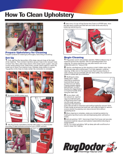
ECONOMY VACUUM OVEN Models: SVAC1E SVAC1E-2 SVAC2E SVAC2E-2 Previously designated as: 1407, 1407-2, 1408, & 1408-2 INSTALLATION AND INSTRUCTION MANUAL 6 / 2014 4861658 Sheldon Manufacturing Inc. P.O. Box 627, Cornelius, Oregon 97113 EMAIL: [email protected] INTERNET: http://www.Shellab.com/~Shellab 1-800-322-4897 (503) 640-3000 FAX (503) 640-1366 TABLE OF CONTENTS SECTION 1.0 RECEIVING AND INSPECTION SECTION 2.0 GRAPHIC SYMBOLS SECTION 3.0 INSTALLATION SECTION 4.0 CONTROL PANEL OVERVIEW SECTION 5.0 PRECAUTIONS SECTION 6.0 VACUUM OPERATION SECTION 7.0 OPERATION SECTION 8.0 MAINTENANCE SECTION 9.0 TROUBLESHOOTING AND SERVICE SECTION 10.0 PARTS LIST UNIT SPECIFICATIONS WIRE DIAGRAM These units are general purpose vacuum ovens for professional, industrial or educational use where the preparation or testing of materials is done at approximately atmospheric pressure and no flammable, volatile or combustible materials are being heated. These units are not intended for hazardous or household locations or use. 2 1 Section RECEIVING AND INSPECTION IMPORTANT: READ THIS INSTRUCTION MANUAL IMMEDIATELY. Your satisfaction and safety require a complete understanding of this unit, including its proper function and operational characteristics. Be sure operators are familiar with these instructions before attempting to put the unit in service. NOTE: This equipment must be used only for its intended application; any alterations or modifications will VOID your warranty. 1.1 Inspection: The carrier, when accepting shipment, also accepts responsibility for safe delivery and is liable for loss or damage claims. On delivery, inspect for visible exterior damage. Note and describe on the freight bill any damage found and enter your claim on the form supplied by the carrier. 1.2 Inspect for concealed loss or damage on the unit itself, both interior and exterior. If any, the carrier will arrange for official inspection to substantiate your claim. 1.3 Return Shipment: Save the shipping carton until you are sure the unit has been delivered in good condition. If for any reason you must return the unit, contact your customer service representative for authorization. Supply the complete data label information when requesting return authorization. Please see the manual cover for information on where to contact customer service. 1.4 Accessories: Verify that all of the equipment indicated on the packing slip is included with the unit. Carefully check all packaging before discarding. The units are equipped with 2 shelves. 3 2 Section GRAPHICS SYMBOLS Your oven is provided with a display of graphic symbols to help in identifying the use and function of the available adjustable components. 2.1 Indicates that you should consult your operation manual for further description and discussion of a control or user item. 2.2 Indicates "AC Power On". 2.3 Indicates "Adjustable Temperature". 2.4 Indicates "Manual Adjustment". 2.5 Indicates "Heating". 2.6 Indicates "Earth Ground" 2.7 Indicates “Potential Shock Hazard” behind partition 2.8 Indicates “Unit should be recycled” (Not disposed of in land-fill) 4 3 Section INSTALLATION Local city, county or other ordinances may govern the use of this equipment. If you have any questions about local requirements, please contact the appropriate local agency. Installation may be performed by the end user. Under normal circumstances this unit is intended for use indoors, at room temperatures between 5 and 40C, at no greater than 80% Relative Humidity (at 25C) and with a supply voltage that does not vary by more than 10%. Customer service should be contacted for operating conditions outside of these limits. 3.1 Power Source: The power source must match the voltage, cycle, phase, and ampere requirements listed on the data plate. This unit is intended for 50/60 HZ application. Plug the cord into a grounded outlet. THE VOLTAGE OF THE OUTLET SHOULD NOT VARY MORE THAN 10% FROM THE DATAPLATE RATING. A separate circuit is recommended to preclude loss of product due to overloading or circuit failure. Note that the electrical supply to the unit must conform to all national and local electrical codes. 3.2 Location: When selecting a site for the unit, consider conditions that may affect performance, such as heat from radiators, ovens, autoclaves, etc. Avoid direct sun, fastmoving air currents, heating/cooling ducts, and high-traffic areas. To ensure air circulation around the unit, allow a minimum of 30 cm between the unit and any walls or partitions that might obstruct free airflow. 3.3 Lifting / Handling: This unit is heavy and care should be taken to use appropriate lifting devices sufficiently rated for such loads. Please see Unit Sepcifications for weight specifications. The unit should only be lifted from the bottom surface. Doors, handles and knobs are not adequate for lifting or stabilization. The unit should be completely restrained from tipping during lifting or transport. All moving parts such as shelves should be removed to prevent shifting and damage. The doors should be positively locked in the closed position during transport. 3.4 Leveling: The unit must sit level and solidly. The unit has four rubber feet that are already attached to the unit and are not adjustable; however, the counter top must be level for maximum working and safety conditions. 3.5 Cleaning: The oven has been cleaned at the factory, but not sterilized and should be disinfected prior to use. Remove all shelving if assembled and clean the chamber with a disinfectant that is appropriate for your application. DO NOT USE chlorine-based bleaches or abrasives as this will damage the interior. DO NOT USE spray cleaners that might leak through openings and cracks and get on electrical parts or that may contain solvents that will harm the coatings. A thorough, periodic cleaning is strongly recommended. WARNING: Never clean the unit with alcohol or flammable cleaners with the unit connected to the electrical supply. Always disconnect the unit from the electrical service when cleaning and assure all volatile or flammable cleaners are evaporated and dry before reattaching the unit to the power supply. 5 3.6 Shelves: See Figure One for proper orientation of shelves. directly on the floor of the chamber. DO NOT place items FIGURE ONE 6 4 Section CONTROL PANEL OVERVIEW 4.1 POWER: The Main Power I/O (ON/OFF) switch controls all power to the oven. It must be in the I, or ON position before any systems are operational. 4.2 HEATING ACTIVATED Light: This pilot lamp is on the when the temperature controller has activated the heating elements to reach and maintain set point. During normal operation this light will be on until the temperature in the chamber gets close to the desired temperature and then will go off and on at regular intervals as the control maintains the temperature within the chamber. 4.3 TEMPERATURE CONTROLLER: The controller is marked SET TEMPERATURE and is equipped with an adjustment knob and a graduated dial. The graduated dial is marked with 10 major increments and 9 minor increments. These increments can be used as index points for setting and returning to set point temperatures. 4.4 VACUUM: The adjustment valve, located on the bottom right corner of the control panel, allows opening and closing of the plumbing to an external vacuum pump or system. Please note that the vacuum valve is the larger of the two valves on the control panel and can be used to vacuum down the chamber. The valve is plumbed to the 3/8” tube on the back of the unit marked “Vacuum”. 4.5 VENT: This adjustment valve, located on the upper right corner of the control panel, controls introduction of gas into the chamber there by relieving vacuum. This valve is plumbed to the ¼” tube in the back of the unit marked “Vent”. 4.6 VACUUM GAUGE: This component, mounted on the control panel adjacent to the two valves, indicates the level of vacuum within the chamber. It has a dual scale and is calibrated in “0 to 76 centimeters of mercury” and “0 to 30 inches of mercury” 7 5 Section PRECAUTIONS 5.1 Do not place or use explosive, combustible, or flammable materials in the oven. 5.2 Do not use sealed containers in the oven chamber. 5.3 Do not cut or remove the ground prong from the power cord or use an ungrounded 2prong adapter plug. 5.4 Disconnect the unit from the electrical power source before attempting to make any repairs or component replacements. 5.5 If a mercury thermometer is used and breakage should occur, all spilled mercury must be completely removed from the chamber. 5.6 THIS IS NOT AN EXPLOSION PROOF OVEN. THIS OVEN IS NOT SUITABLE FOR USE IN CLASS I, II, OR III LOCATIONS, AS DEFINED BY THE NATIONAL ELECTRICAL CODE NFPA 70. 5.7 This oven is not intended, nor can it be used, as a patient connected device. 8 6 Section VACUUM OPERATION 6.1 A pump with a pumping capacity four times greater than the chamber volume is advisable. The SVAC1E (1407) & SVAC1E-2 (1407-2) have a chamber volume of .6 cubic feet, so a pump with a pumping capacity of 4 cubic feet per minute is recommended. When working below 1mm, a diffusion type pump will be needed. The SVAC2E (1408) & SVAC2E-2 (1408-2) have a chamber volume of 1.5 cubic feet so a pump with a capacity of 6 cubic feet per minute is recommended. 6.2 IT IS IMPORTANT TO USE VACUUM TUBING FOR ALL THE VACUUM HOOKUPS. OTHER TYPES OF TUBING MAY COLLAPSE AND PREVENT COMPLETE EVACUATION. 6.3 To Apply Vacuum to the Chamber: Attach the hose from the vacuum pump to the 3/8” tube marked “Vacuum” on the rear of the unit. Close the vent valve on the control panel. Open the vacuum valve on the control panel. Latch the door shut and start the vacuum pump. This action will hold the door shut and against the gasket until the pump creates a vacuum in the chamber. Once a good vacuum seal is accomplished, the door will hold itself shut and sealed until the chamber is returned to atmospheric pressure. 6.4 Watch the VACUUM GAUGE and when the required vacuum is obtained, close the vacuum valve and then turn the pump off. The VACUUM GAUGE is incremented from 0 to 30 inches of Hg (76 cm of Hg) with zero representing atmospheric pressure. 6.5 Vacuum Relief: To return the chamber to atmospheric pressure, open the vent valve very slowly (the one not connected to the vacuum), and allow the chamber to return to atmospheric pressure. The speed at which the vacuum is relieved can be controlled by how much the valve is opened. 9 7 Section OPERATION 7.1 Power Supply: Connect the service cord to a grounded outlet and push the power switch to the ON position. 7.2 Place a reference thermometer inside the chamber where it can be easily viewed through the window, then vacuum down the chamber as described in Vacuum Operation Section. 7.3 Setting Temperature: The operating range for this oven is 40C - 210C. To set the Temperature Controller turn the control knob to the desired oven temperature, using the graduated dial as a reference guide. Allow at least one hour for the temperature to stabilize. Using a reference thermometer, verify the oven temperature, if it is not the correct value, turn the control knob up or down as needed. Allow the temperature to restabilize, and continue this process until the exact desired temperature is achieved. NOTE: Slight vapor or smoke may occur in the initial heat-up. This is a normal occurrence when the oven is first brought up to temperature and protective coatings on the element heat up. 10 8 Section MAINTENANCE Note: Prior to any maintenance or service on this unit, disconnect the service cord from the power supply. 8.1 Cleaning: Clean the oven interior on a regular basis. To prepare the oven for cleaning, remove the shelves and door gasket. A. First clean the removed shelves and interior with an appropriate cleaner or solvent. To decontaminate use a disinfectant that is suitable to your application. DO NOT use chlorine-based bleaches or abrasives, as this will damage the stainless steel surfaces. B. When cleaning the gasket, extreme care must be taken so as not to damage the gasket material. Generally speaking solvents should not be used as they may damage the gasket material. Also handle the gasket carefully so as not to impair the positive seal. 8.2 If the oven is to be shut down for storage or transporting, remove shelves, be certain the chamber is dry, latch the door closed and disconnect the power cord. 8.3 There is no maintenance required on electrical components. If the oven fails to operate as specified, see Troubleshooting before calling for service. 11 9 Section TROUBLESHOOTING AND SERVICE Always make a visual inspection of the oven and control console when troubleshooting. Look for loose or disconnected wires or tubing, which may be the source of the problem. The oven is designed so that no internal electrical servicing should be required under normal conditions. If electrical servicing is necessary, it should be performed by qualified service personnel. TEMPERATURE Temperature too high 1/ controller failed on – call Customer Service Temperature too low 1/ unit not recovered from door opening 2/ unit not recovered from power failure or being turned off 3/ element failure – see if heating light is on; compare current draw to data plate 4/ controller failure – confirm with front panel light that controller is calling for heat Unit will not heat up at all 1/ verify that controller is asking for heat by looking for controller light – if pilot light is not on continuously during initial start up, there is a problem with the controller 2/check amperage – amperage should be virtually at maximum rated (data plate) amperage MECHANICAL Door not sealing 1/ check physical condition of gasket 2/ adjust hinges and latch to insure that the glass is laying flat against the gasket 3/ Confirm that unit has not been damaged and body is not out of square. Unit won’t hold vacuum 1/ check door gasket for damage, wear or improper installation. 2/ assure all vent and feed valves are closed tightly 3/ assure tight connections to pump OTHER Unit or wall fuse/circuit breaker is blown 1/ check wall power source 2/ compare current draw and compare to specs on data plate 3/ see what other loads are on the wall circuit Unit will not turn on 1/ check wall power source 2/ check fuse/circuit breaker on unit or in wall 3/ see if unit is on, e.g., heater, and just controller is off Unit is smoking – Out of box This is not uncommon during initial operation. Put unit under vent and run at full power for one hour. Contamination in chamber 1/ see cleaning procedure in operator’s manual 2/ develop and follow standard operating procedure for specific application; include definition of cleaning technique and maintenance schedule SERVICE: If this product should require service, contact your service representative. Should return of the product be necessary, a return authorization number must be obtained and the product shipped prepaid, to the proper service center. To insure prompt handling, the return authorization number should be placed on the outside of the package or container. Make sure a detailed explanation of the reason for return is enclosed with the unit. For information on where to contact customer service, please see the manual cover. 12 Section 10 PARTS LIST DESCRIPTION PART NUMBER Control Knob Door Glass SVAC1E (1407) & SVAC1E-2 (1407-2) 4450528 3550542 Door Glass SVAC2E (1408) & SVAC2E-2 (1408-2) 3550540 Heating Element I/O (ON/OFF) Switch Pilot Light Power Cord 120v Power Cord 230v Temperature Controller Vent Valve Vacuum Valve Vacuum Gauge Shelf SVAC1E (1407) & SVAC1E-2 (1407-2) 9570939 7850570 4650554 1800529 1800541 1750863 9990736 9990737 9990618 5680566 5680567 1750748 Shelf SVAC2E (1408) & SVAC2E-2 (1408-2) Temp Limit Thermostat Fuse SVAC1E (1407), SVAC1E-2 (1407-2), SVAC2E (1408) SVAC2E-2 (1408-2): T6.3A 250v 3300515 DOOR GASKETS AVAILABLE: Material SVAC1E (1407) SVAC1E-2 (1407-2) SVAC2E (1408) SVAC2E-2 (1408-2) Silicone, Red Fluorosilicone Viton Buna-N 3450508 3450610 3450669 3450712 3450707 3450611 3450670 3450708 13 UNIT SPECIFICATIONS Weight SVAC1E (1407) & SVAC1E-2 (1407-2) SVAC2E (1408) & SVAC2E-2 (1408-2) Dimensions Shipping Net 71 lbs. 59.4 lbs. 154 108 lbs. Exterior WxDxH Interior WxDxH SVAC1E (1407) & 14.25 x 19.5 x 22.25 SVAC1E-2 (1407-2) SVAC2E (1408) & 17.5 x 27.75 x 27.75 SVAC2E-2 (1408-2) Capacity SVAC1E (1407) & SVAC1E-2 (1407-2) SVAC2E (1408) & SVAC2E-2 (1408-2) 9” x 12” x 9” 12” x 20” x 12” Cubic Feet 0.6 1.6 Temperature Range SVAC1E (1407) & SVAC1E-2 (1407-2) + 15C to 210C SVAC2E (1408) & SVAC2E-2 (1408-2) + 15C to 210C Uniformity +3.0C @ 60C +9.0C @ 120C +13.0C @ 200C +3.0C @ 60C +9.0C @ 120C +13.0C @ 200C Rise Time 30 min. to 120C 30 min. to 120C 14 WIRE DIAGRAM SVAC1E (1407) 115V 13A US CORD 1800529 BLACK WHITE WHI TE HT BLACK HT 218˚C 50.5 OHMS 270 WATTS TAN ULTRA HT THERMOSTAT 1750863 TAN ULTRA HT 50.5 OHMS 270 WATTS TAN ULTRA HT BLACK HT LIMIT DISK 1750748 TAN ULTRA HT GREEN LIGHTED SWITCH 103351 HEAT LIGHT 4650554 BLACK BLACK 9851152 15 WIRE DIAGRAM SVAC1E-2 (1407-2) 230V 13A EUROPE CORD1800541 BROWN BLUE WHITE HT BLACK HT GREEN LIGHTED SWITCH 103351 BLACK HT 50.5 OHMS 270 WATTS THERMOSTAT 1750863 TAN ULTRA HT LIMIT DISK 1750748 218˚C TAN ULTRA HT TAN ULTRA HT 50.5 OHMS 270 WATTS HEAT LIGHT 4650554 BLACK BLACK 9851153 16 WIRE DIAGRAM SVAC2E (1408) 115V 13A US CORD 1800516 BLACK WHITE WHITE HT BLACK HT GREEN LIGHTED SWITCH 103351 50.5 OHMS 270 WATTS TAN ULTRA HT 50.5 OHMS 270 WATTS TAN ULTRA HT BLACK HT TAN ULTRA HT 50.5 OHMS 270 WATTS LIMIT DISK 1750748 218˚C TAN ULTRA HT THERMOSTAT 1750863 50.5 OHMS 270 WATTS HEAT LIGHT 4650554 BLACK BLACK 9851154 17 WIRE DIAGRAM SVAC2E-2 (1408-2) 230V 13A EUROPE CORD1800541 BROWN BLUE WHITE HT BLACK HT GREEN LIGHTED SWITCH 103351 50.5 OHMS 270 WATTS 50.5 OHMS 270 WATTS TAN ULTRA HT LIMIT DISK 1750748 THERMOSTAT 1750863 TAN ULTRA HT 50.5 OHMS 270 WATTS TAN ULTRA HT TAN ULTRA HT BLACK HT TAN ULTRA HT TAN ULTRA HT 50.5 OHMS 270 WATTS 218˚C HEAT LIGHT 4650554 BLACK BLACK 9851155 18


© Copyright 2026