
Installation, Operation and Maintenance Manual MX Series
Installation, Operation and
Maintenance Manual
MX Series
Rotary Screw Modular Chillers
50 to 125 Tons
Copyright 2009 Thermal Care
Table of Contents
Foreword ............................................................................................................................................................................. 1
Safety Guidelines ................................................................................................................................................................. 1
General Information ............................................................................................................................................................ 2
Table 1 – Water Cooled Chiller General Data (60 Hz) .......................................................................................................... 2
Table 2 – Remote Air Cooled Condenser Chiller General Data (60 Hz) ................................................................................ 3
Figure 1 – Model Number Description ................................................................................................................................ 4
Capacity Data ...................................................................................................................................................................... 5
MXW Chiller Ratings................................................................................................................................................................. 5
Table 3 – Water Cooled Chiller Performance Data (60 Hz) .................................................................................................. 5
MXR Chiller Ratings .................................................................................................................................................................. 7
Table 4 – Remote Air Cooled Chiller Performance Data (60 Hz) .......................................................................................... 7
Installation .......................................................................................................................................................................... 9
Receiving Inspection ................................................................................................................................................................ 9
Rigging, Handling, and Locating Equipment ............................................................................................................................. 9
Foundation ............................................................................................................................................................................... 9
Electrical Power........................................................................................................................................................................ 9
Table 5 – Chiller Electrical Data (60 Hz) ............................................................................................................................. 11
Table 6 – Remote Air-Cooled Condenser Electrical Data (60 Hz)....................................................................................... 11
Condenser Water Line ........................................................................................................................................................... 11
Figure 2 – MXW Series Condenser Water Pressure Drop .................................................................................................. 12
Table 7 – Water Cooled Condenser Water Flow Rate Requirements ................................................................................ 12
Chilled Water Line .................................................................................................................................................................. 13
Figure 3 – MXW/MXR Series Evaporator Water Pressure Drop ........................................................................................ 13
Table 8 - Chilled Water Flow Rate Requirements .............................................................................................................. 14
Interconnecting Refrigerant Piping ........................................................................................................................................ 14
Water Pressure Gauges .......................................................................................................................................................... 15
Remote Process Sensor .......................................................................................................................................................... 15
System Fluid Freeze Protection.............................................................................................................................................. 15
System Refrigerant and Oil Charge .................................................................................................................................... 15
MXW Chillers .......................................................................................................................................................................... 15
MXR Chillers ........................................................................................................................................................................... 15
Operating Principles .......................................................................................................................................................... 16
Coolant Circuit........................................................................................................................................................................ 16
Refrigerant Circuit .................................................................................................................................................................. 16
Oil Circuit ................................................................................................................................................................................ 16
Components ...................................................................................................................................................................... 17
Chilled Water In Temperature Sensor ................................................................................................................................... 17
Chilled Water Out Temperature Sensor................................................................................................................................. 17
Compressor ............................................................................................................................................................................ 17
Compressor Electronic Motor Module .................................................................................................................................. 17
Compressor Internal Relief Valve ........................................................................................................................................... 17
Compressor Service Valve ...................................................................................................................................................... 17
Condenser Remote Air-Cooled .............................................................................................................................................. 17
Condenser Water-Cooled....................................................................................................................................................... 18
Condenser Water In Temperature Sensor ............................................................................................................................. 18
Condenser Water Out Temperature Sensor .......................................................................................................................... 18
Condenser Water Regulating Valve ....................................................................................................................................... 18
Coolant Flow Switch ............................................................................................................................................................... 18
Crankcase Heater ................................................................................................................................................................... 18
Discharge Check Valve ........................................................................................................................................................... 18
Discharge Pressure Sensor ..................................................................................................................................................... 18
Discharge Temperature Sensor .............................................................................................................................................. 18
Electronic Expansion Valve (EEV) ........................................................................................................................................... 19
Evaporator ............................................................................................................................................................................. 19
High Refrigerant Pressure Switch ........................................................................................................................................... 19
Human Machine Interface (HMI) ........................................................................................................................................... 19
Liquid Line Check Valve .......................................................................................................................................................... 19
Liquid Injection Solenoid Valve .............................................................................................................................................. 19
Liquid Line Solenoid Valve ..................................................................................................................................................... 20
Loader / Unloader Solenoid Valve ......................................................................................................................................... 20
Oil Filter .................................................................................................................................................................................. 20
Oil Level Switch ...................................................................................................................................................................... 20
Oil Separator .......................................................................................................................................................................... 20
Oil Service Valve ..................................................................................................................................................................... 20
Oil Sight Glass ......................................................................................................................................................................... 20
Oil Temperature Sensor ......................................................................................................................................................... 20
Pressure Relief Valve .............................................................................................................................................................. 20
Process Supply Temperature Sensor...................................................................................................................................... 20
Receiver.................................................................................................................................................................................. 21
Refrigerant Filter/Drier .......................................................................................................................................................... 21
Refrigerant Service Valve ....................................................................................................................................................... 21
Refrigerant Sight Glass ........................................................................................................................................................... 21
Suction Pressure Sensor ......................................................................................................................................................... 21
Suction Temperature Sensor ................................................................................................................................................. 21
Water Service Valves (Optional) ............................................................................................................................................ 21
Y Strainer ................................................................................................................................................................................ 21
Operator Interface ............................................................................................................................................................. 22
HMI Screens and Setup .......................................................................................................................................................... 22
Overview ............................................................................................................................................................................ 22
Chiller ................................................................................................................................................................................. 23
Chiller Statistics .................................................................................................................................................................. 24
Security .............................................................................................................................................................................. 24
System Options .................................................................................................................................................................. 27
Chiller Options ................................................................................................................................................................... 28
Mode.................................................................................................................................................................................. 28
Chiller Setup ....................................................................................................................................................................... 28
Menu .................................................................................................................................................................................. 29
Tuning – MXR Models ........................................................................................................................................................ 29
Tuning – MXW Models....................................................................................................................................................... 32
Chiller Operation .................................................................................................................................................................... 35
Runtime Hours ................................................................................................................................................................... 36
Alarm List ........................................................................................................................................................................... 36
I/O View ............................................................................................................................................................................. 37
Graphics ............................................................................................................................................................................. 38
Service Info ........................................................................................................................................................................ 39
Clock Calendar Setup ......................................................................................................................................................... 40
HMI Screen Navigation .......................................................................................................................................................... 41
Control System Parameters ................................................................................................................................................... 44
Table 9 – Parameter List .................................................................................................................................................... 44
Alarm Banner Summary..................................................................................................................................................... 45
Chiller Compressor Fault ........................................................................................................................................................ 45
Chiller Compressor High Pressure Fault ................................................................................................................................. 46
Chiller Compressor Low Pressure Fault.................................................................................................................................. 46
Chiller Crankcase Oil Level Low Fault ..................................................................................................................................... 46
Chiller Compressor Run Contactor Fault ................................................................................................................................ 46
Chiller Compressor Run Contactor Overload ......................................................................................................................... 46
Chiller Compressor Start Contactor Fault .............................................................................................................................. 46
Chiller Compressor Start Contactor Overload ........................................................................................................................ 46
Chiller E-Stop Pressed or MCR Off ......................................................................................................................................... 46
Chiller Flow Switch Fault ........................................................................................................................................................ 46
Chiller Freezestat Fault .......................................................................................................................................................... 47
Chiller Glycol Warning ............................................................................................................................................................ 47
Chiller High Superheat Alarm ................................................................................................................................................. 47
Chiller Leaving Water High Temperature Alarm .................................................................................................................... 47
Chiller Low Superheat Fault ................................................................................................................................................... 47
Chiller Open Pressure Transducer Fault ................................................................................................................................. 47
Chiller Refrigerant High Pressure Fault .................................................................................................................................. 47
Chiller Refrigerant Low Pressure Fault ................................................................................................................................... 47
Chiller TC Module Slot 1 Ch.(X) Alarm .................................................................................................................................... 48
Condenser Fan VFD Alarm ..................................................................................................................................................... 48
Maximum Differential Pressure ............................................................................................................................................. 48
Minimum Differential Pressure .............................................................................................................................................. 48
PLC Battery Low ..................................................................................................................................................................... 48
Power Phase Fault .................................................................................................................................................................. 48
Remote Temperature Sensor Fault ........................................................................................................................................ 48
Control Sequence .............................................................................................................................................................. 49
Startup and Running Sequence .............................................................................................................................................. 49
Shutdown Sequence .............................................................................................................................................................. 49
Table 10 – System Compressor Staging ............................................................................................................................. 50
Initial Startup .................................................................................................................................................................... 50
Table 11 - Recommended Glycol Solutions ....................................................................................................................... 51
Preventive Maintenance ................................................................................................................................................... 53
Once a Week .......................................................................................................................................................................... 53
Once a Month ........................................................................................................................................................................ 53
Once a Year ............................................................................................................................................................................ 54
Maintenance ..................................................................................................................................................................... 54
Installing and Replacing Processor Battery ............................................................................................................................ 54
Replacing a Fuse on the Power Supply .................................................................................................................................. 54
Cleaning the Operator Interface ............................................................................................................................................ 55
Checking Compressor Oil Level .............................................................................................................................................. 55
Warranty Information ....................................................................................................................................................... 56
PLC Troubleshooting .......................................................................................................................................................... 57
Table 12 - Processor Status LEDs ....................................................................................................................................... 57
General Troubleshooting ................................................................................................................................................... 58
Preventive Maintenance Checklist ..................................................................................................................................... 60
Foreword
The intent of this manual is to serve as a guide for placing your central chiller in service and operating and maintaining it
properly. Improper installation can lead to poor equipment performance or severe equipment damage. Failure to follow the
installation instructions may result in damage not covered by your warranty. It is extremely important that a qualified
refrigeration installation contractor perform all installation line sizing and piping. Please supply these instructions to your
authorized refrigeration contractor. This manual is for our standard product line with supplements as required to
accommodate any special items provided for a specific application. The written information contained in this manual, as
well as various drawings, are intended to be general in nature. The drawings included in this manual are typical only and
may not represent the actual unit purchased. Actual drawings are included with the equipment for troubleshooting and
servicing of the unit. Additional copies of drawings are available upon request. We strive to maintain an accurate record of
all equipment during the course of its useful life. Every effort was made to standardize the design features of these chillers,
the various options may make it necessary to rearrange some of the components; therefore, some of the general drawings
in this manual may differ from your specific unit.
Due to the ever-changing nature of applicable codes, ordinances, and other local laws pertaining to the use and operation
of this equipment we do not reference them in this manual. There is no substitute for common sense and good operating
practices when placing any mechanical equipment into operation. We encourage all personnel to familiarize themselves
with this manual's contents. Failure to do so may unnecessarily prolong equipment down time.
The chilling equipment uses chemical refrigerants for heat transfer purposes. This chemical is sealed and tested in a
pressurized system containing ASME coded vessels; however, a system failure will release it. Refrigerant gas can cause toxic
fumes if exposed to fire. Place these units in a well-ventilated area, especially if open flames are present.
Failure to follow these instructions could result in a hazardous condition. The standard refrigerant used in these units is a
hydro fluorocarbon (HFC) trade named R-134A. We strongly recommend our customers implement a refrigerant
management program including a survey of all equipment to document the type and quantity of refrigerant in each
machine. We recommend all refrigeration service technicians be licensed and certified by an EPA approved organization.
Follow good piping practices and the information in this manual to insure a successful installation and operation of this
equipment. We are not responsible for liabilities created by substandard piping methods and installation practices external
to the chiller.
We trust your equipment will have a long and useful life. If you should have any questions, please contact our Customer
Service Department specifying the serial number and model number of the unit as indicated on the nameplate.
Safety Guidelines
Observe all safety precautions during installation, startup, and service of this equipment due to the presence of high
voltage and refrigerant charge. Only qualified personnel should install, startup, and service this equipment.
When working on this equipment, observe precautions in literature, and on tags, stickers, and labels located on the
equipment. Wear work gloves and safety glasses.
WARNING: This equipment contains hazardous voltages that can cause severe injury or death. Disconnect and lock out incoming
power before installing or servicing the equipment.
WARNING: This equipment contains refrigerant under pressure. Accidental release of refrigerant under pressure can cause personal
injury and or property damage. Exercise care while working on or around this equipment.
WARNING: Vent all refrigerant relief valves in accordance to ANSI/ASHRAE Standard 15, Safety Code for Mechanical Refrigeration.
This equipment should be located within a well-ventilated area. Inhalation of refrigerant can be hazardous to your health and the
accumulation of refrigerant within an enclosed space can displace oxygen and cause suffocation.
1
General Information
Table 1 – Water Cooled Chiller General Data (60 Hz)
Model
MXW50
MXW75
MXW100
MXW125
1
1
1
1
74.4
101.0
126.0
Compressor
Quantity
Nominal Capacity (ton)
53.0
Number of Capacity Steps
Continuously Variable Capacity Adjustment
Minimum Unloaded Capacity (ton)
18.0
28.0
34.0
42.0
Fluid Volume (gal)
12
17
24
28
Maximum Refrigerant Pressure (psig)
400
400
400
400
Refrigerant Pressure Relief Valve Setting (psig)
400
400
400
Condenser
Refrigerant Pressure Relief Valve (in)
5
/8 SAE Flare
5
/8 SAE Flare
3
/4 FPT
400
3
/4 FPT
Refrigerant Pressure Relief Valve Flow Capacity (lbs. of air/min)
26.8
26.8
54.0
54.0
Maximum Fluid Pressure (psig)
150
150
150
150
Fluid Inlet Flange Connection (in)
3
4
4
4
Fluid Outlet Flange Connection (in)
3
4
4
4
Evaporator
8
10
12
15
Maximum Refrigerant Pressure (psig)
Fluid Volume (gal)
450
450
450
450
Maximum Fluid Pressure (psig)
450
450
450
450
Fluid Inlet Flange Connection (in)
3
4
4
4
Fluid Outlet Flange Connection (in)
3
4
4
Fluid Drain NPT Connection (in)
1
/2
1
/2
1
/2
4
1
/2
General Information
Refrigerant Type
2
R134a
R134a
R134a
R134a
Refrigerant Charge (lb)
75
105
140
175
Oil Charge (oz)
507
744
744
744
Shipping Weight (lb)
2,965
3,915
4,315
5,020
Operating Weight (lb)
3,145
4,095
4,575
5,330
Table 2 – Remote Air Cooled Condenser Chiller General Data (60 Hz)
Model
MXR50
MXR75
MXR100
MXR125
1
1
1
1
67.5
91.8
114.9
Compressor
Quantity
Nominal Capacity (ton)
47.6
Number of Capacity Steps
Continuously Variable Capacity Adjustment
Minimum Unloaded Capacity (ton)
18.0
28.0
34.0
42.0
Maximum Refrigerant Pressure (psig)
400
400
400
400
Refrigerant Pressure Relief Valve Setting (psig)
400
400
400
400
Condenser
Refrigerant Pressure Relief Valve SAE Flare (in)
Refrigerant Pressure Relief Valve Capacity (lbs. of air/min)
Liquid Line Connection (in)
Discharge Line Connection (in)
5
/8
5
/8
5
/8
5
/8
26.8
26.8
26.8
26.8
3
1 /8
5
1 /8
1
2 /8
2 1/8
1
5
5
3 1/8
2 /8
2 /8
2 /8
Evaporator
8
10
12
15
Maximum Refrigerant Pressure (psig)
Fluid Volume (gal)
450
450
450
450
Maximum Fluid Pressure (psig)
450
450
450
450
3
4
4
4
Fluid Inlet Flange Connection (in)
Fluid Outlet Flange Connection (in)
Fluid Drain NPT Connection (in)
3
1
/2
4
1
/2
4
1
/2
4
1
/2
General Information
Refrigerant Type
Refrigerant Charge (lb)
Oil Charge (oz)
R134a
R134a
R134a
R134a
Varies based on system refrigerant piping – see Installation Guidelines
507
744
744
744
Shipping Weight Chiller (lb)
2,495
3,340
3,485
3,700
Operating Weight Chiller (lb)
2,620
3,510
3,710
3,980
Shipping Weight Remote Condenser (lb)
1,600
2,810
2,885
4,050
Operating Weight Remote Condenser (lb)
Varies base on system refrigerant charge and operating conditions
3
Figure 1 – Model Number Description
Unit Model
Digit Number
MX
1,2
W
3
075
4,5,6
A
7
M
8
Digits 1,2
Chiller Type
MX = Modular Rotary Screw Compressor
Digit 3
Condenser Type
R = Remote Air-Cooled Condenser
W = Integral Water-Cooled Condenser
4
9
S
10
Digits 4,5,6 Nominal Compressor Cooling Capacity
050 = 50 ton
075 = 75 ton
100 = 100 ton
125 = 125 ton
Digit 7
Digit 8
Digit 9
Development Sequence
A = First Development Series
Controller Type
M = Master Controller
S = Slave controller
E = Engineered
Main Power Input
3 = 230/3/60
4 = 460/3/60
5 = 575/3/60
E = Engineered
Digit 10
Design Efficiency
H = High Efficiency
S = Standard Efficiency
Digit 11
Operating Range
S = Standard Temperature Range (20°F to 80°F)
E = Engineered
Digit 12
Refrigerant Type
1 = R134a
2 = R404a
3 = R507
4 = R407c
4
S
11
1
12
13
1
14
0
15
1
16
1
17
0
18
0
19
Digit 14
Panel Type
1 = NEMA-4/12 (Standard Non Flange)
2 = NEMA-12 (Flange Disconnnect)
3 = NEMA-4 (Flange Disconnect)
Digit 15
Disconnect Type
0 = No Disconnect
1 = Rotary Non-Fused
2 = Flange Non-Fused
Digit 16
Water Service Valves
0 = Without Water Service Valves
1 = With Water Service Valves
Digit 17
Alarm Horn
0 = No Alarm Horn
1 = Alarm Horn
Digit 18
Stack Light
0 = No Stacklight
1 = Stack Light
2 = Engineered
Digit 19
Sound Blanket
0 = No Sound Blanket
1 = With Sound Blanket
Capacity Data
MXW Chiller Ratings
All performance data is based on:
1. Coolant temperature rise of 10°F (5.6°C)
2. Cooler fouling factor of 0.0001 ft2 • hr • °F/Btu (0.000018 m3 • kW)
3. Condenser fouling factor of 0.00025 ft2 • hr • °F/Btu (0.000044 m3 • kW)
4. Subcooling of 10°F (5.6°C)
5. Refrigerant R-134A
Table 3 – Water Cooled Chiller Performance Data (60 Hz)
LCWT1
(°F)
20
25
30
35
40
42
44
Model
2
Cap
MXW50
MXW75
MXW100
MXW125
MXW50
MXW75
MXW100
MXW125
MXW50
MXW75
MXW100
MXW125
MXW50
MXW75
MXW100
MXW125
MXW50
MXW75
MXW100
MXW125
MXW50
MXW75
MXW100
MXW125
MXW50
MXW75
MXW100
MXW125
27.8
38.6
52.3
66.3
31.5
43.7
59.1
74.8
35.5
49.3
66.3
83.9
39.7
55.2
74.1
93.7
44.7
62.7
85.0
106.3
46.5
65.3
88.1
110.7
48.4
67.9
91.7
115.1
80
Cooler
Input Flow
3
kW
Rate
(gpm)
33.1
73.8
45.5 102.5
59.4 139.1
75.8 176.2
33.6
82.0
46.2 113.9
60.7 153.9
77.4 194.8
34.3
90.7
46.9 126.0
62.0 169.7
79.1 214.5
35.0
99.9
47.7 138.9
63.3 186.5
81.0 235.7
35.8 106.9
48.7 149.9
65.2 203.6
83.4 254.5
36.1 111.4
49.1 156.3
64.6 211.0
84.2 265.0
36.4 116.0
49.5 162.7
65.1 219.6
85.0 275.8
Cond4
Flow
Cap2
Rate
(gpm)
89.5
26.8
124.1
37.3
166.7
50.9
211.6
64.4
98.8
30.5
137.0
42.4
183.8
57.5
233.1
72.7
108.9
34.4
150.8
47.8
202.2
64.6
256.2
81.6
119.6
38.6
165.7
53.6
221.9
72.2
281.1
91.2
132.1
43.4
184.3
60.9
249.4
82.8
313.2 103.6
136.8
45.2
190.8
63.5
256.5
86.0
324.2 107.8
141.6
47.1
197.5
66.1
265.4
89.5
335.5 112.2
Condenser Entering Water Temperature (°F)
85
90
Cooler Cond4
Cooler
Input
Flow Flow
Input Flow
Cap2
3
3
kW
Rate
Rate
kW
Rate
(gpm) (gpm)
(gpm)
34.7
71.3
88.5
25.9
36.5
68.8
47.8
99.2 122.8
36.0
50.4
95.7
62.9 135.2 165.7
49.3
66.5 131.0
80.0 171.2 210.1
62.5
84.4 166.0
35.3
79.4
97.7
29.4
37.1
76.7
48.5 110.4 135.4
41.0
51.1 106.8
64.1 149.7 182.5
55.8
67.8 145.3
81.6 189.4 231.2
70.6
86.0 183.8
36.0
88.0 107.6
33.3
37.8
85.1
49.3 122.3 149.1
46.3
51.9 118.5
65.4 165.1 200.5
62.7
69.1 160.4
83.3 208.8 253.9
79.3
87.7 202.9
36.7
97.1 118.2
37.4
38.6
94.0
50.1 135.0 163.7
52.0
52.7 130.9
66.8 181.7 219.9
70.2
70.4 176.7
85.1 229.5 278.3
88.7
89.6 223.2
37.6 103.9 130.4
42.1
39.5 100.8
51.2 145.8 182.0
59.1
53.8 141.5
68.4 198.2 246.6
80.5
72.1 192.6
87.5 248.0 309.8 100.8
92.1 241.2
37.9 108.3 135.0
43.9
39.8 105.1
51.6 152.0 188.4
61.6
54.2 147.6
69.0 206.0 254.7
83.8
72.7 200.6
88.4 258.3 320.6 105.0
92.9 251.3
38.2 112.9 139.7
45.7
40.2 109.5
52.0 158.4 195.0
64.2
54.6 153.8
69.5 214.5 263.5
87.2
73.3 208.9
89.2 268.9 331.7 109.2
93.8 261.7
95
Cond4
Cooler
Flow
Input
Flow
Cap2
3
Rate
kW
Rate
(gpm)
(gpm)
87.5
24.9
38.4
66.1
121.5
34.7
53.2
92.2
164.6
47.7
70.3 126.7
208.6
60.4
89.2 160.6
96.5
28.4
39.1
73.9
134.0
39.5
53.9 103.0
181.1
54.0
71.6 140.7
229.3
68.4
90.8 178.1
106.2
32.1
39.8
82.1
147.3
44.8
54.7 114.5
198.8
60.8
73.0 155.5
251.6
76.9
92.6 196.8
116.7
36.1
40.6
90.9
161.7
50.4
55.5 126.7
217.8
68.1
74.3 171.4
275.6
86.1
94.5 216.7
128.7
40.7
41.5
97.5
179.6
57.3
56.7 137.1
243.7
78.1
76.0 186.9
306.4
97.9
96.9 234.3
133.2
42.5
41.9 101.7
185.9
59.7
57.1 143.1
252.0
81.4
76.6 194.8
317.0 102.0
97.8 244.2
137.9
44.3
42.2 106.1
192.4
62.3
57.5 149.2
260.7
84.7
77.2 203.0
328.0 106.2
98.7 254.4
Cond4
Flow
Rate
(gpm)
86.4
120.3
163.5
207.3
95.3
132.6
179.7
227.6
104.9
145.7
197.0
249.4
115.1
159.8
215.6
273.0
126.9
177.3
240.9
303.1
131.4
183.5
249.1
313.6
135.9
189.9
257.6
324.3
Notes:
1. LCWT = Leaving Coolant Temperature
2. Cap = Capacity in tons of refrigeration
3. kW = Compressor motor input power at rated voltage
4. Cond = Condenser
5.
= Requires antifreeze protection of system fluid. See Application Consideration section for more details. Capacities, energy use, and flows based
upon ethylene glycol solutions as follows based on Leaving Coolant Temperature: 15% for 35°F, 20% for 30°F, 25% for 25°F, and 30% for 20°F.
5
MXW Chiller Ratings
All performance data is based on:
1. Coolant temperature rise of 10°F (5.6°C)
2. Cooler fouling factor of 0.0001 ft2 • hr • °F/Btu (0.000018 m3 • kW)
3. Condenser fouling factor of 0.00025 ft2 • hr • °F/Btu (0.000044 m3 • kW)
4. Subcooling of 10°F (5.6°C)
5. Refrigerant R-134AAll performance data is based on:
Table 3 – Water Cooled Chiller Performance Data (60 Hz) - Continued
LCWT1
(°F)
46
48
50
55
60
65
70
75
Model
2
Cap
MXW50
MXW75
MXW100
MXW125
MXW50
MXW75
MXW100
MXW125
MXW50
MXW75
MXW100
MXW125
MXW50
MXW75
MXW100
MXW125
MXW50
MXW75
MXW100
MXW125
MXW50
MXW75
MXW100
MXW125
MXW50
MXW75
MXW100
MXW125
MXW50
MXW75
MXW100
MXW125
50.4
70.7
95.3
119.7
52.4
73.5
99.1
124.4
54.4
76.4
102.8
129.2
59.8
84.0
113.4
141.8
65.6
92.1
124.7
155.3
71.6
100.6
135.6
173.1
74.0
103.5
137.8
173.1
74.0
103.5
140.3
173.1
80
Cooler
Input
Flow
kW3
Rate
(gpm)
36.7
120.8
49.9
169.4
65.7
228.5
85.9
286.9
37.0
125.6
50.3
176.2
66.2
237.5
86.7
298.2
37.4
130.6
50.7
183.3
66.8
246.7
87.6
309.9
38.3
143.6
51.8
201.6
68.5
272.1
89.9
340.5
39.3
157.5
53.1
221.1
70.9
299.6
92.3
373.0
40.3
172.2
54.4
241.9
71.8
326.0
95.5
416.0
40.7
178.0
54.9
248.9
72.8
331.4
95.5
416.2
40.7
178.2
54.9
249.1
72.3
337.7
95.5
416.5
Cond4
Flow
Cap2
Rate
(gpm)
146.5
49.0
204.4
68.8
274.6
93.1
347.0 116.7
151.5
51.0
211.5
71.6
283.9
96.8
358.9 121.3
156.7
53.0
218.7
74.4
293.4 100.5
371.2 126.0
170.3
58.3
237.8
81.9
320.0 111.1
403.2 138.4
184.8
63.9
258.1
89.8
349.0 121.4
437.3 151.7
200.2
69.9
279.7
98.2
375.9 132.4
482.2 168.3
206.2
71.8
286.9 100.5
381.7 134.0
482.2 168.3
206.2
71.8
286.9 100.5
387.4 133.9
482.2 168.3
Notes:
1. LCWT = Leaving Coolant Temperature
2. Cap = Capacity in tons of refrigeration
3. kW = Compressor motor input power at rated voltage
4. Cond = Condenser
6
Condenser Entering Water Temperature (°F)
85
90
Cooler Cond4
Cooler
Input Flow Flow
Input Flow
2
Cap
kW3
Rate
Rate
kW3
Rate
(gpm) (gpm)
(gpm)
38.6 117.5 144.6
47.6
40.5 114.1
52.4 164.9 201.8
66.9
55.1 160.3
70.1 223.2 272.5
90.7
73.8 217.5
90.1 279.7 343.1 113.6
94.6 272.4
38.9 122.3 149.6
49.5
40.9 118.7
52.8 171.6 208.7
69.6
55.5 166.8
70.7 232.0 281.7
94.3
74.4 226.2
91.0 290.9 354.8 118.2
95.5 283.4
39.3 127.1 154.7
51.5
41.2 123.5
53.3 178.5 215.9
72.4
56.0 173.6
71.2 241.0 291.1
98.0
75.0 235.0
91.9 302.4 366.8 122.8
96.5 294.6
40.2 139.9 168.1
56.7
42.2 136.0
54.5 196.5 234.7
79.7
57.3 191.2
72.9 266.7 317.8 108.2
76.7 259.8
94.2 332.4 398.4 135.0
98.9 324.1
41.2 153.5 182.3
62.2
43.3 149.3
55.8 215.7 254.7
87.5
58.7 210.1
74.5 291.6 343.7 116.7
78.1 280.4
96.7 364.4 432.0 163.5 104.5 392.8
42.3 167.9 197.4
68.0
44.3 163.5
57.3 236.1 276.1
95.7
60.2 230.1
76.2 318.3 371.5 131.1
79.3 315.0
99.8 404.6 474.2 163.5 104.5 393.0
42.6 172.7 202.3
69.5
44.6 167.2
57.7 241.7 281.8
97.4
60.5 234.3
76.4 322.2 375.3 129.9
80.2 312.5
99.8 404.8 474.2 163.5 104.5 393.3
42.6 172.8 202.3
69.5
44.6 167.3
57.7 241.8 281.8
97.4
60.5 234.4
76.4 322.4 375.3 129.9
80.2 312.7
99.8 405.1 474.2 163.5 104.5 393.5
95
Cond4
Cooler
Flow
Input Flow
Cap2
Rate
kW3
Rate
(gpm)
(gpm)
142.6
46.1
42.6 110.5
199.1
64.9
58.0 155.5
269.6
88.2
77.8 211.3
339.2 110.5
99.6 264.9
147.5
48.0
43.0 115.1
206.0
67.5
58.4 161.9
278.7
91.7
78.4 219.9
350.7 114.9 100.5 275.6
152.6
49.9
43.4 119.8
213.1
70.3
58.9 168.5
287.9
95.3
79.0 228.5
362.6 119.5 101.5 286.6
165.7
55.0
44.4 132.0
231.6
77.4
60.2 185.9
313.8 105.9
79.7 254.3
393.6 131.4 104.0 315.5
179.7
60.4
45.4 145.1
251.3
85.1
61.7 204.3
335.2 113.6
82.2 273.0
466.3 158.6 109.7 381.0
194.6
66.1
46.5 158.9
272.3
94.3
63.5 226.6
370.6 125.8
84.1 302.5
466.3 158.6 109.7 381.2
198.4
67.2
46.7 161.5
276.6
94.3
63.5 226.7
368.6 125.8
84.1 302.6
466.3 158.6 109.7 381.5
198.4
67.2
46.7 161.6
276.6
94.3
63.5 226.9
368.6 125.8
84.1 302.8
466.3 158.6 109.7 381.8
Cond4
Flow
Rate
(gpm)
140.6
196.5
266.4
335.3
145.5
203.3
275.3
346.7
150.4
210.2
284.4
358.4
163.3
228.4
310.6
389.0
177.1
247.9
331.0
458.5
191.7
271.4
361.8
458.5
194.3
271.4
361.7
458.5
194.3
271.4
361.7
458.5
MXR Chiller Ratings
All performance data is based on:
1. Coolant temperature rise of 10°F (5.6°C)
2. Cooler fouling factor of 0.0001 ft2 • hr • °F/Btu (0.000018 m3 • kW)
3. Subcooling of 10°F (5.6°C)
4. Refrigerant R-134A
Table 4 – Remote Air Cooled Chiller Performance Data (60 Hz)
85
LCWT1
(°F)
Model
Cap2
MXR50
20
MXR75
MXR100
MXR125
MXR50
25
MXR75
MXR100
MXR125
MXR50
30
MXR75
MXR100
MXR125
MXR50
35
MXR75
MXR100
MXR125
MXR50
40
MXR75
MXR100
MXR125
MXR50
42
MXR75
MXR100
MXR125
MXR50
44
MXR75
MXR100
MXR125
MXR50
46
MXR75
MXR100
MXR125
MXR50
48
MXR75
MXR100
MXR125
MXR50
50
MXR75
MXR100
MXR125
26.8
37.4
51.0
64.5
30.3
42.2
57.3
72.4
33.9
47.3
64.0
80.8
37.7
52.7
71.1
89.7
42.1
59.4
80.9
101.1
43.7
61.7
84.0
105.0
45.4
64.1
87.2
108.9
47.1
66.5
90.5
113.0
48.9
69.0
93.8
117.2
50.6
71.5
97.3
121.4
Input
kW3
34.7
47.6
62.5
79.7
35.7
48.8
64.5
82.2
36.8
50.1
66.6
84.9
38.0
51.6
68.8
87.8
39.5
53.5
71.7
91.6
40.0
54.1
72.7
92.9
40.6
54.8
73.7
94.2
41.2
55.6
74.6
95.6
41.8
56.3
75.7
97.0
42.4
57.1
76.7
98.5
Cooler
Flow
Rate
(gpm)
71.3
99.5
135.6
171.5
78.8
110.0
149.2
188.6
86.7
121.0
163.7
206.7
94.9
132.7
179.0
225.8
100.8
142.1
193.6
242.0
104.8
147.8
201.2
251.4
108.8
153.5
209.0
261.0
113.0
159.4
216.9
270.9
117.2
165.5
225.0
281.0
121.5
171.6
233.3
291.3
Cap2
24.9
34.9
47.9
60.6
28.2
39.5
53.9
68.1
31.6
44.3
60.3
76.2
35.3
49.5
67.1
84.7
39.4
55.8
76.2
95.5
41.0
58.0
79.2
99.2
42.6
60.3
82.2
103.0
44.2
62.6
85.3
106.9
45.9
65.0
88.5
110.8
47.6
67.5
91.8
114.9
Condenser Entering Air Temperature (°F)
95
105
Cooler
Input
Flow
Input
Cap2
kW3
Rate
kW3
(gpm)
38.3
52.8
69.8
88.8
39.4
54.1
71.9
91.3
40.6
55.5
74.1
94.2
42.0
57.1
76.3
97.3
43.5
59.1
79.4
101.3
44.1
59.8
80.4
102.7
44.7
60.6
81.4
104.1
45.4
61.4
82.5
105.7
46.0
62.2
83.6
107.2
46.7
63.0
84.7
108.9
66.2
92.7
127.3
161.1
73.4
102.8
140.4
177.5
80.9
113.4
154.1
194.8
88.8
124.5
168.7
213.1
94.4
133.6
182.4
228.5
98.1
139.0
189.6
237.5
102.0
144.5
197.0
246.7
105.9
150.1
204.6
256.1
110.0
155.9
212.3
265.8
114.1
161.8
220.1
275.6
22.8
32.1
44.5
56.5
25.9
36.5
50.2
63.6
29.1
41.2
56.2
71.2
32.6
46.1
62.6
79.3
36.5
52.0
71.2
89.5
38.0
54.2
74.0
93.0
39.5
56.3
76.9
96.7
41.0
58.6
79.8
100.4
42.6
60.8
82.8
104.2
44.2
63.1
85.9
108.0
42.5
59.3
78.0
99.2
43.8
60.6
80.2
102.0
45.1
62.1
82.4
105.0
46.6
63.7
84.8
108.3
48.3
65.8
88.0
112.6
48.9
66.6
89.1
114.1
49.5
67.4
90.1
115.7
50.2
68.2
91.2
117.4
50.9
69.1
92.4
119.1
51.6
70.1
93.5
120.9
115
Cooler
Flow
Rate
(gpm)
60.5
85.4
118.3
150.0
67.4
95.1
130.7
165.7
74.6
105.3
143.8
182.2
82.1
115.9
157.6
199.6
87.4
124.5
170.4
214.2
91.0
129.7
177.2
222.8
94.6
135.0
184.2
231.6
98.4
140.4
191.3
240.6
102.2
145.9
198.6
249.8
106.1
151.5
206.0
259.2
Cap2
20.5
29.3
40.9
52.0
23.4
33.4
46.2
58.8
26.5
37.8
51.8
66.0
29.7
42.5
57.8
73.7
33.4
48.1
65.8
83.2
34.8
50.1
68.4
86.6
36.2
52.2
71.1
90.0
37.6
54.3
73.9
93.5
39.1
56.4
76.7
97.1
40.6
58.6
79.6
100.8
Input
kW3
47.6
67.4
87.3
111.3
48.9
68.7
89.6
114.2
50.4
70.2
91.9
117.5
52.0
71.9
94.4
121.1
53.7
74.0
97.7
125.7
54.4
74.8
98.8
127.4
55.1
75.7
99.9
129.1
55.8
76.6
101.1
130.9
56.6
77.5
102.3
132.8
57.3
78.5
103.5
134.8
Cooler
Flow
Rate
(gpm)
54.4
77.8
108.6
138.3
60.9
87.0
120.3
153.1
67.7
96.7
132.6
168.8
74.8
106.9
145.5
185.4
79.9
115.1
157.4
199.2
83.3
120.0
163.8
207.3
86.7
125.0
170.4
215.7
90.2
130.1
177.1
224.2
93.8
135.3
183.9
232.9
97.5
140.6
190.9
241.9
Notes:
1. LCWT = Leaving Coolant Temperature
2. Cap = Capacity in tons of refrigeration
3. kW = Compressor motor input power at rated voltage
4.
= Requires antifreeze protection of system fluid. See Application Consideration section for more details. Capacities, energy use, and flows based
upon ethylene glycol solutions as follows based on Leaving Coolant Temperature: 15% for 35°F, 20% for 30°F, 25% for 25°F, and 30% for 20°F.
7
MXR Chiller Ratings
All performance data is based on:
1. Coolant temperature rise of 10°F (5.6°C)
2. Cooler fouling factor of 0.0001 ft2 • hr • °F/Btu (0.000018 m3 • kW)
3. Subcooling of 10°F (5.6°C)
4. Refrigerant R-134A
Table 4 – Remote Air Cooled Chiller Performance Data (60 Hz) – Continued
85
LCWT1
(°F)
Model
Cap2
MXR50
55
MXR75
MXR100
MXR125
MXR50
60
MXR75
MXR100
MXR125
MXR50
65
MXR75
MXR100
MXR125
MXR50
70
MXR75
MXR100
MXR125
MXR50
75
MXR75
MXR100
MXR125
55.3
78.1
106.1
132.5
60.1
85.1
115.5
144.1
65.2
92.4
124.6
156.4
65.9
93.2
124.6
156.8
65.9
93.2
124.6
156.8
Input
kW3
44.0
59.3
79.5
102.5
45.8
61.7
82.5
106.8
47.7
64.3
85.4
111.4
47.9
64.6
85.4
111.6
47.9
64.6
85.4
111.6
Cooler
Flow
Rate
(gpm)
132.6
187.6
254.8
318.0
144.3
204.4
277.4
346.2
156.6
222.0
299.4
375.9
158.4
224.1
299.6
377.2
158.5
224.2
299.8
377.5
Notes:
1. LCWT = Leaving Coolant Temperature
2. Cap = Capacity in tons of refrigeration
3. kW = Compressor motor input power at rated voltage
8
Cap2
51.9
73.8
100.2
125.5
56.5
80.4
109.1
136.7
61.3
87.2
116.6
147.5
61.4
87.2
116.6
147.5
61.4
87.2
116.6
147.5
Condenser Entering Air Temperature (°F)
95
105
Cooler
Input
Flow
Input
Cap2
kW3
Rate
kW3
(gpm)
48.4
65.4
87.6
113.2
50.3
68.0
90.7
117.9
52.3
70.8
93.4
122.6
52.3
70.8
93.4
122.6
52.3
70.8
93.4
122.6
124.7
177.1
240.5
301.2
135.8
193.1
262.0
328.3
147.4
209.7
280.4
354.5
147.6
209.8
280.5
354.7
147.7
210.0
280.7
355.0
48.4
69.2
93.9
118.1
52.7
75.5
102.2
128.8
56.6
81.1
108.3
137.8
56.6
81.1
108.3
137.8
56.6
81.1
108.3
137.8
53.5
72.6
96.6
125.6
55.5
75.3
99.9
130.7
57.3
77.9
102.4
135.3
57.3
77.9
102.4
135.3
57.3
77.9
102.4
135.3
115
Cooler
Flow
Rate
(gpm)
116.1
166.0
225.3
283.6
126.6
181.3
245.6
309.4
136.1
195.0
260.4
331.3
136.2
195.2
260.5
331.5
136.3
195.3
260.7
331.7
Cap2
44.5
64.3
87.1
110.4
48.6
70.4
95.0
120.6
51.7
74.9
99.6
127.9
51.7
74.9
99.6
127.9
51.7
74.9
99.6
127.9
Input
kW3
59.3
81.2
106.7
140.0
61.3
84.1
110.2
145.6
62.9
86.5
112.3
149.8
62.9
86.5
112.3
149.8
62.9
86.5
112.3
149.8
Cooler
Flow
Rate
(gpm)
106.9
154.5
209.0
265.1
116.8
169.0
228.1
289.7
124.2
180.0
239.5
307.3
124.2
180.1
239.6
307.5
124.3
180.2
239.8
307.7
Installation
Receiving Inspection
Each chiller is skid mounted and plastic wrapped prior to shipment. If the chiller has a remote air-cooled condenser, the
condenser will ship skid mounted and will contain a holding charge of nitrogen. Before accepting delivery, check the overall
equipment condition for any visible damage and document any evident on the delivery receipt. Shipping damage is the
responsibility of the carrier. In order to expedite payment for damages, it is important to follow proper procedures and
record keeping. Photographs of damaged equipment are excellent documentation for your records.
Inspect for hidden damage after removing the packing. Refrigerant lines can be susceptible to damage in transit. Check for
broken lines, oil leaks, damaged controls, or any other major component torn loose from its mounting point.
Our Customer Service Department will provide assistance in preparation and filing of your claims, including arranging for an
estimate and quotation on repairs; however, filing the claim is the responsibility of the receiving party.
Rigging, Handling, and Locating Equipment
The units have a structural steel frame. Use proper rigging methods to prevent damage to components. Avoid impact
loading caused by sudden jerking when lifting or lowering the chiller. Use pads on any abrasive surface contact areas. The
frame supporting the unit is for positioning the unit with a crane or a forklift. Please refer to the drawings provided with the
chiller for chiller rigging details. If the chiller has a remote air-cooled condenser, please refer to the Remote Condenser
Installation Guidelines manual for further instructions on locating and rigging the remote condenser. This separate
document has been prepared to assist refrigeration contractors with the installation and piping design for our remote
condensers.
As standard, these chillers are for indoor use. Standard units are for indoor use and should not be installed or even stored
in an outdoor location; however, some custom units are for outdoor installations. The unit can be stored in environments
between -22°F (-30°C) and 122°F (50°C) and is designed for operation in environments between 30°F (-1°C) and 110°F
(43°C).
CAUTION: To prevent damage to the equipment caused by freezing, do not store or operate the unit in an ambient which may cause
freezing without adequate freeze protection
Serviceability was a primary concern when designing your central chiller. Do not compromise this feature by locating the
chiller in an inaccessible area. Please allow a minimum of 3 feet around the perimeter of the chiller for required clearance
around the chiller. If it is necessary to store the chiller in an unheated area when not in use, drain all water from the unit or
add an adequate amount of antifreeze to prevent freeze-up of the unit.
Foundation
Provide a rigid mounting surface for the chiller of adequate strength to support the operating weight of the chiller. It is
imperative to include the entire operating weight, including the completed piping and full operating weight of the
refrigerant and water, in total operating weight support requirements.
The chiller once mounted should be level within a 1/4” over the length and width of the unit.
Electrical Power
All wiring must comply with local codes and the National Electric Code. Minimum Circuit Ampacities (MCA) and other unit
electrical data are on the unit nameplate are in Table 5 – Chiller Electrical Data (60 Hz) and Table 6 – Remote Air-Cooled
Condenser Electrical Data (60 Hz).
A specific electrical schematic is shipped with the unit. Measure each leg of the main power supply voltage at the main
power source. Voltage must be within the voltage utilization range given in Table 5 – Chiller Electrical Data (60 Hz). If the
measured voltage on any leg is not within the specified range, notify the supplier and correct before operating the unit.
Voltage imbalance must not exceed two percent. Excessive voltage imbalance between the phases of a three-phase system
can cause motors to overheat and eventually fail.
9
Voltage imbalance is determined using the following calculations:
%Imbalance = (Vavg – Vx) x 100 / Vavg
Vavg = (V1 + V2 + V3) / 3
Vx = phase with greatest difference from Vavg
For example, if the three measured voltages were 442, 460, and 454 volts, the average would be:
(442 + 460 + 454) / 3 = 452
The percentage of imbalance is then:
(452 – 442) x 100 / 452 = 2.2 %
This exceeds the maximum allowable of 2%.
The unit includes a terminal block for main power connection to the main power source. The main power source should be
connected to the terminal block through an appropriate disconnect switch. A separate lug for grounding the unit is in the
main control panel. Check the electrical phase sequence at installation and prior to Startup. Operation of the compressor
with incorrect electrical phase sequencing will result in mechanical damage to the compressors. Check the phasing with a
phase sequence meter prior to applying power. The proper sequence should read ABC on the meter. If the meter reads
CBA, open the main power disconnect and switch two line leads on the line power terminal blocks (or the unit mounted
disconnect). All components are wired and phased correctly at the factory. Do not interchange any load leads that are from
the unit contactors or the motor terminals.
WARNING: It is imperative that L1-L2-L3 are connected in the A-B-C phase sequence to prevent equipment damage due to reverse
rotation.
CAUTION: The unit requires the main power to remain connected during off-hours to energize the compressor’s crankcase heater.
Disconnect main power only when servicing the chiller. The crankcase heater should remain on when the compressor is off to ensure
liquid refrigerant does not accumulate in the compressor crankcase.
WARNING: The control panel and safeties such that connecting the appropriate power source to the main terminal block energizes
the entire electric circuitry of the chiller. A control transformer and power supply has been factory wired to step down the incoming
power to the 115VAC and 24VDC control power. Electric power at the main disconnect should be shut off before opening access panels
for repair or maintenance. Ground the unit properly in compliance with local and national codes.
10
Table 5 – Chiller Electrical Data (60 Hz)
Model
MXW50
MXW75
MXW100
MXW125
MXR50
MXR75
MXR100
MXR125
Voltage Utilization
Rated
Voltage
Min
Max
460/3/60
575/3/60
460/3/60
575/3/60
460/3/60
575/3/60
460/3/60
575/3/60
460/3/60
575/3/60
460/3/60
575/3/60
460/3/60
575/3/60
460/3/60
575/3/60
414
518
414
518
414
518
414
518
414
518
414
518
414
518
414
518
506
632
506
632
506
632
506
632
506
632
506
632
506
632
506
632
Number of
Power
Connections
1
1
1
1
1
1
1
1
1
1
1
1
1
1
1
1
Compressor Data
Number of
Conductors
RLA
3
3
3
3
3
3
3
3
3
3
3
3
3
3
3
3
112
90
137
109
166
133
219
175
112
90
137
109
166
133
219
175
1
LRA
2
267
212
433
346
563
449
716
577
267
212
433
346
563
449
716
577
Unit Data
MCA
3
MOCP4
142
114
173
138
209
168
275
220
142
114
173
138
209
168
275
220
250
200
300
225
350
300
450
350
250
200
300
225
350
300
450
350
Notes:
1. RLA is Rated Load Amps
2. LRA is Locked Rotary Amps
3. MCA is Minimum Circuit Ampacity (for wire sizing)
4. MOCP is Maximum Overcurrent Protection
Table 6 – Remote Air-Cooled Condenser Electrical Data (60 Hz)
Model
Rated
Voltage4
Voltage Utilization
Min
414
414
414
414
Max
506
506
506
506
Number of Power
Connections
Number of
Conductors
LAVF-14412
460/3/60
1
3
LEVF-16410
460/3/60
1
3
LAVF-24410
460/3/60
1
3
LAVF-25410
460/3/60
1
3
Notes:
1. RLA is Rated Load Amps
2. MCA is Minimum Circuit Ampacity (for wire sizing)
3. MOCP is Maximum Overcurrent Protection
4. 575/3/60 remote condensers require special selection and pricing. Consult factory for details.
Fan Data
Qty
4
6
8
10
Unit Data
1
RLA Each
3.5
3.5
3.5
3.5
MCA
15
22
29
36
2
MOCP3
20
30
35
45
Condenser Water Line
(MXW Models Only) The performance of a condenser is dependent on maintaining the proper flow and temperature of
water through the heat exchanger. Insufficient water flow or high condenser water supply temperature will result in the
reduction of cooling capacity of the chiller. Extreme conditions will eventually result in the chiller shutting down due to high
refrigerant pressure. If condenser fouling by contaminants in the condenser water stream occurs, performance is negatively
affected. In order to reduce maintenance costs and chiller downtime, a water treatment program is highly recommended
for the condenser cooling water. If condenser plugging occurs, contact our Customer Service Department for assistance in
the proper procedure for cleaning out the condenser.
Caution: The use of untreated or improperly treated water in a chiller can result in scaling, erosion, algae, or slime buildup. This can
lead to poor system performance or premature failure.
The standard cooling capacity assumes 85°F (29°C) condenser cooling water supply. Under normal operating conditions,
there will be approximately 10°F (6°C) rise through the condenser resulting in 95°F (35°C) exiting water temperature from
the condenser. To ensure proper water flow through the condenser, the condenser water pump must be able to supply the
pressure drop given in Figure 2 – MXW Series Condenser Water Pressure Drop when providing the required condenser
water flow.
11
Figure 2 – MXW Series Condenser Water Pressure Drop
25.00
MXW125
MXW100
Pressure Drop (PSI)
20.00
15.00
MXW50
10.00
5.00
0.00
0
100
200
300
400
500
600
Water Flow Rate (GPM)
Nominal condenser water flow rates based on 50°F leaving chiller water temperature and 85°F entering condenser cooling
water are given in Table 7 – Water Cooled Condenser Water Flow Rate Requirements. For conditions other than nominal,
reference the condenser water flows listed in Table 3 – Water Cooled Chiller Performance Data (60 Hz). Do not exceed the
minimum and maximum limits in Table 7 – Water Cooled Condenser Water Flow Rate Requirements. Flow rates greater
than the maximum will cause excessive tube erosion and lead to premature tube failure. Flow rates less than the minimum
will result in excessive tube fouling and reduced heat transfer.
Table 7 – Water Cooled Condenser Water Flow Rate Requirements
Chiller Model
MXW50
MXW75
MXW100
MXW125
Minimum Flow
gpm (lpm)
psid (kPA)
22 (83)
0.1 (0.7)
29 (110)
0.1 (0.7)
32 (121)
0.1 (0.7)
43 (163)
0.2 (1.4)
Nominal Flow
gpm (lpm)
psid (kPA)
155 (587)
5.2 (35.9)
216 (818)
4.8 (33.1)
293 (1109)
10.6 (73.1)
367 (1389)
12.0 (82.7)
Maximum Flow
gpm (lpm)
psid (kPA)
221 (837)
10.6 (73.1)
295 (1117)
9.0 (62.1)
403 (1526)
20.0 (137.9)
487 (1844)
21.1 (145.5)
The pressure drop given in Figure 2 – MXW Series Condenser Water Pressure Drop, is the minimum pressure drop required
in order that the condenser water-regulating valve operates below a 60° open position. Above 60° open position, the valve
flow characteristics are non-linear and can result in poor controllability. The condenser water-regulating valve controls the
condenser water flow in order to maintain the discharge pressure set point. The chiller loading, condenser water inlet
temperature, and discharge pressure set point determine the actual flow. The chiller starts and operates with a condenser
water supply temperature range from 55°F (12.8°C) to 105°F (40.6°C). However, for the most efficient and stable chiller
operation, it is recommended to maintain the condenser water supply temperature range from 65°F (18.3°C) to 85°F
(29.4°C). To prevent damage to the condenser or regulating valve, the condenser water pressure should not exceed 150
PSIG (1035 kPa).
The water-regulating valve will modulate the flow rate of condenser water through the condenser in order to maintain the
discharge pressure set point. If the discharge pressure is above the set point, the water-regulating valve will open to
increase the water flow attempting to provide more cooling. The condenser water flow can exceed nominal flow rates
during these conditions and reduce the available water flow through other processes if sharing the same pump.
Warning: If the condenser water pump is feeding other sources in addition to the chiller, it is highly recommended to install a circuit
setter in line with the chiller in order to limit the maximum flow through the chiller.
12
Chilled Water Line
To prevent unwanted condensation, insulate all chilled water piping. If water condenses on the piping, the state change of
the water from gas to liquid will result in a substantial heat load that becomes an additional burden for the chiller.
Standard central chillers provide 50°F (10°C) coolant to the process. Under normal operating conditions there will be a 10°F
(6°C) rise through the process resulting in 60°F (16°C) return coolant temperature to the chiller.
The importance of properly sized piping between the chiller and process cannot be overemphasized. See the ASHRAE
Handbook or other suitable design guide for proper pipe sizing. In general, run full size piping out to the process and then
reduce the pipe size to match the connections on the process equipment. Poorly designed piping is one of the most
common causes of unsatisfactory chiller performance. Avoid unnecessarily long lengths of hoses or quick disconnect fittings
that offer high resistance to water flow. When manifolds are required for water distribution, install them as close to the use
point as possible. Provide flow-balancing valves at each chilled water use point to assure adequate water distribution in the
entire system. Figure 3 – MXW/MXR Series Evaporator Water Pressure Drop provides the pressure drop through the
evaporator and chilled water piping associated with the chiller. Use this information for assistance when sizing a chilled
water pump. Nominal chilled water flow rates are provided in Table 8 - Chilled Water Flow Rate Requirements, and are
based on a 10°F (18°C) range across the evaporator at 50°F (10°C) LWT and 85°F (29.4°C) entering condenser water or 95°F
(35°C) ambient air for remote air cooled chillers. For other leaving chilled water temperatures, refer to Table 3 – Water
Cooled Chiller Performance Data (60 Hz) and Table 4 – Remote Air Cooled Chiller Performance Data (60 Hz).
Figure 3 – MXW/MXR Series Evaporator Water Pressure Drop
45.00
MXW/MXR100
MXW/MXR125
40.00
35.00
MXW/MXR50
MXW/MXR75
Pressure Drop (PSI)
30.00
25.00
20.00
15.00
10.00
5.00
0.00
0
100
200
300
400
500
600
700
Water Flow Rate (GPM)
13
Table 8 - Chilled Water Flow Rate Requirements
Minimum Flow
Nominal Flow*
gpm (lpm)
psid (kPA)
gpm (lpm)
psid (kPA)
MXW50
62 (235)
1.9 (13.1)
127 (481)
8.1 (55.8)
MXW75
88 (333)
1.9 (13.1)
179 (678)
7.9 (54.5)
MXW100
118 (447)
2.5 (17.2)
242 (916)
10.5 (72.4)
MXW125
148 (560)
2.6 (17.9)
302 (1143)
11.0 (75.8)
MXR50
56 (212)
1.6 (11.0)
114 (432)
6.5 (44.8)
MXR75
78 (295)
1.5 (10.3)
162 (613)
6.4 (44.1)
MXR100
105 (397)
2.0 (13.8)
220 (833)
8.7 (60.0)
MXR125
133 (503)
2.1 (14.5)
276 (1045)
9.2 (63.4)
* Nominal flow required to meet capacity at standard conditions of 60°F (15°C) EWT and 50°F (10°C) LWT
Chiller Model
Maximum Flow
gpm (lpm)
psid (kPA)
250 (946)
31.4 (216.5)
350 (1325)
30.0 (206.8)
470 (1779)
39.7 (273.7)
592 (2241)
42.2 (291.0)
224 (848)
25.2 (173.7)
312 (1181)
23.8 (164.1)
420 (1590)
31.7 (218.6)
532 (2014)
34.1 (235.1)
The minimum flow rates are required to prevent fouling and to ensure the chiller stays within normal refrigerant operating
conditions.
If the process flow requirement is lower than the minimum flow limitation shown in Table 8 - Chilled Water Flow Rate
Requirements, multiple smaller chillers may be used. Another alternative is to use a primary pumping loop designed for
lower flow at a higher temperature rise through the process and a secondary pumping loop designed for a higher flow and
lower temperature drop through the chiller. If a secondary pumping loop is used, maintain the mixed temperature of
coolant entering the evaporator at a minimum of at least 5°F (2.8°C) above the set point of the chiller.
The maximum flow limitation shown in Table 8 - Chilled Water Flow Rate Requirements, is the theoretical limits of the
chiller based upon a 5°F (2.8°C) drop across the cooler; however, these flows result in impractical pressure drops through
the cooler and are therefore not likely for a system design. If the process flow requirement is higher than the maximum
flow limitation shown in Table 8 - Chilled Water Flow Rate Requirements, a bypass around the chiller may be used. Another
alternative is to use a primary pumping loop designed for higher flow and lower temperature rise through the process and a
secondary pumping loop designed for lower flow and higher temperature drop through the chiller. If a secondary pumping
loop is used, maintain the mixed temperature of coolant entering the cooler at a minimum of at least 5°F (2.8°C) above the
set point of the chiller.
The use of varying cooler flows is sometimes necessary; however, it is highly recommended to use a dedicated evaporator
circulation pump to provide increased system stability. The controls of the chiller are very adaptable and are capable of
adjusting to variations in the flow of water through the system and will load and unload compressor(s) as needed to
maintain tight control of the leaving water temperature of the system. If the cooler flow is varied, the minimum fluid loop
volume must be in excess of 3 gallons of coolant per ton of cooling (3.2 L per kW) and the flow rate must change at a rate of
no greater than 10% per minute in order to maintain an acceptable level of temperature control. This is a practical amount
of water which typically buffers fluctuations in the process enough that the chiller will generally see fairly gradual rates of
change in the inlet water temperature and will be able to accurately load or unload the compressor(s) which in turn will
allow for very consistent and stable supply temperatures to the process. Use a system volume of 6 to 10 gallons of coolant
per ton (6.4 to 10.8 L per kW) if the flow rate changes more rapidly than 10% per minute. If the chiller sees a net rates of
change greater than 10% per minute it may result in temporary supply temperature fluctuations greater than 1°F (0.56°C).
Interconnecting Refrigerant Piping
(MXR Models Only) The chiller unit has a full charge of oil, excluding the additional charge for field piping, and a refrigerant
holding charge. The chiller is for use only with the air-cooled condenser provided with the unit. The following section covers
the required piping between the chiller and the provided air-cooled condenser.
Caps are located on the discharge and liquid lines. These line sizes do not necessarily reflect the actual line sizes required
for the piping between the chiller and the air-cooled condenser. The installing contractor need only provide the
interconnecting piping between the chiller and the air-cooled condenser.
Refrigerant piping size and piping design has a significant effect on system performance and reliability. For specific pipe
sizing and configuration, refer to the MXR Series Chiller Remote Air Cooled Condenser Installation Guidelines Manual. All
piping should conform to the applicable local and state codes. Use refrigerant grade copper tubing only and isolate the
refrigeration lines from building structures to prevent transfer of vibration. Do not use a saw to remove end caps. This
might allow copper chips to contaminate the system. Use a tube cutter or heat to remove the caps. When sweating copper
joints it is important to flow dry nitrogen through the system. This prevents scale formation. Do not use soft solders. For
14
copper-to-copper joints use a phos-copper solder with 6% to 8% silver content. Use a high silver content brazing rod for
copper-to-brass or copper-to-steel joints. Only use oxy-acetylene brazing.
Water Pressure Gauges
It is highly recommended to install pressure gauges or taps (field supplied) in the inlet and outlet of both the condenser and
evaporator chilled water piping. The ability to read the pressure drop across the chiller is important and will aid in
preventive maintenance and in troubleshooting the chiller performance.
Remote Process Sensor
When using multiple chiller modules together to form a single system, a remote process-supply temperature sensor is field
installed in the common chilled water supply piping. This sensor should be installed downstream of all individual chilled
water supply streams. This sensor will be the control sensor for the chilled water set point and will determine the
loading/unloading of all compressors. Select the ‘Remote Temp Sensor’ in the system options screen within the HMI. It is
possible to use a remote process sensor with a single chiller if the chilled water control point is not local to the chiller.
Mount the sensor in a ½” NPT coupling in minimum pipe size of 3”. The probe sheath is ½” OD x 3” in length and is
equipped with a ½” NPT fitting for direct mounting in a coupling. The sensor is equipped with a NEMA 4 sensor head. Wiring
must be field provided from the sensor head to the chiller electrical enclosure and landed at the designated terminal blocks
within the enclosure. Please see the electrical schematic provided for further detail.
System Fluid Freeze Protection
For applications where system fluid will be exposed to ambient conditions of 32°F (0°C) or colder and/or the set point of the
system will be below 40°F (4.4°C), antifreeze must be added to the system fluid to protect the chiller and system piping
from potential damage. The amount of antifreeze will vary depending on the actual desired operating conditions and
should be enough to provide freeze protection to temperatures 15°F (8.3°C) colder than the coldest temperature
anticipated. Use only antifreeze solutions designed for heat exchanger duty. Do not use automotive antifreeze due to the
potential for fouling that can occur once its relatively short-lived inhibitors break down.
System Refrigerant and Oil Charge
MXW Chillers
Water-cooled MXW chillers receive a full refrigerant and oil charge and run test at the factory prior to shipping. No
additional refrigerant charge is required during startup unless shipping damage occurred and a refrigerant leak resulted.
MXR Chillers
The approximate amount of the refrigerant charge required by the system can be determined by referring to the MXR
Series Chiller Remote Air-Cooled Condenser Installation Guidelines Manual. To verify the actual system charge, run the
system and check the liquid line sight glass to verify proper superheat and subcooling.
The chiller is factory charged with the amount of oil required by the chiller only and not the total system. The amount of
additional oil required is dependent upon the amount of field-installed piping. Please see the MXR Series Chiller Remote Air
Cooled Condenser Installation Guidelines Manual for the additional oil that is required. Check the oil level after the chiller
has run for 15 minutes. View the oil level within the compressor sight glass while the compressor is running. If oil is
required, add it through the compressor oil service valve. Solest 170 is the only approved oil for this system.
15
Operating Principles
Coolant Circuit
The coolant pump, external to the chiller, circulates coolant through the process piping and then back to the chiller. Upon
entering the chiller, the coolant will pass through a y-strainer, which filters the process fluid before entering the evaporator.
Heat transferred from the coolant to the refrigerant occurs in the evaporator. Varying the amount of heat transferred in the
evaporator determines the loading of the compressor, which maintains the temperature set point of the coolant delivered
to the process. A “Process Return” thermocouple senses the temperature of the coolant as it enters the evaporator.
After leaving the evaporator, the coolant passes by a flow switch and the “Process Supply” thermocouple. The
thermocouple senses the temperature of the coolant delivered to process and communicates this temperature to the PLC
controller. This thermocouple also functions as a freezestat. If the multiple modules are installed and are controlling as a
system, a remote process supply sensor is installed downstream of the main coolant supply header to sense the common to
process temperature. This sensor is the control sensor for the PLC control system.
Refrigerant Circuit
The heat transferred in the evaporator from the coolant to the refrigerant changes the state of the refrigerant from a liquid
to a gas. This refrigerant gas then moves from the evaporator to the compressor.
The compressor is the heart of the refrigeration circuit. Cool, low-pressure gas enters the compressor and hot, highpressure gas exits the compressor. Since the compressor is not 100% efficient, some extra heat gain occurs as the
refrigerant is compressed.
The hot, high-pressure gas exiting the compressor goes to the condenser. In water-cooled condenser units (MXW models),
the heat is transferred from the refrigerant flow around the tubes to the water that is flowing through the tubes. In aircooled condenser units (MXR models), the heat is transferred from the refrigerant in the finned tubes to the air that is
flowing across the finned tubes. As the heat transfer occurs, the refrigerant changes from a gas to a liquid. The condenser
removes the heat from the process load and the heat that added by the compressor.
After leaving the condenser, the liquid refrigerant passes through the filter dryer and sight glass. The filter dryer filters out
any particles and/or moisture from the refrigerant. Use the sight glass to monitor the stream of liquid refrigerant. The liquid
refrigerant then passes through the electronic expansion valve, which meters the flow into the evaporator where the
process begins again.
Oil Circuit
The compressor uses oil to control the discharge temperature, lubricate the compressor bearings, and seal the rotors. The
compressor has a vessel directly attached to the end of the compressor, which acts as an oil reservoir and contains the oil
separator. Due to the pressure difference between the suction and discharge sides of the compressor, the oil flows from
the reservoir through a filter to the bearing chambers and to the profile spaces of the rotors. The oil travels in the direction
of compression and flows with the compressed refrigerant into the reservoir vessel. In the reservoir vessel, oil separation
from the refrigerant occurs and it collects in bottom of vessel where the process repeats.
16
Components
Chilled Water In Temperature Sensor
The thermocouple sensor is in the rear of the evaporator and senses the temperature of the chilled water entering the
evaporator. The chilled water in temperature is on the HMI screen. This probe is directly in the evaporator water, there is
not a sensor well included.
Chilled Water Out Temperature Sensor
This thermocouple sensor is in the chilled water piping leaving the evaporator and provides readings of the chilled water
out temperature to the PLC. This temperature sensor input to the PLC is the control sensor if there is only one chiller
installed and the ‘Local Temp Sensor’ is selected in the system options screen. This temperature input is also used as the
freezestat. If the chilled water out temperature falls below the freezestat set point, the compressor will shutdown in order
to protect the chilled water from freezing in the evaporator. This probe is directly in the evaporator water, there is not a
sensor well included.
Compressor
The MX series chillers use semi-hermetic, direct-drive helical rotary type screw compressors with an integral three-stage oil
separator and filter. Each compressor has two rotors, “male” and “female”, which provide compression. The motor
attaches to and drives the male rotor. The male rotor, in turn, drives the female rotor. Separately housed bearing sets are
at each end of both rotors. The helical rotary compressor is a positive displacement device. The refrigerant from the
evaporator goes into the suction opening, across the motor, and into the intake of the compressor rotor section where it is
compressed. The gas then flows through the integral oil separator and finally out of the compressor at the discharge port.
The compressor is also equipped with infinite or four step capacity control, start unloading, an economizer port, liquid
injection cooling, external oil cooling, suction and discharge service valves, discharge check valve, internal pressure relief
valve, oil sight glass, oil insertion type heater, oil service valve, oil level safety, suction gas filter, and an electronic
protection device. Depending on your exact chiller configuration, the compressor may not contain all the available items as
listed above.
The position of the slider valve determines compressor load capacity. The slider valve moves along the length of the rotor
profile and controls the amount of suction gas flow. The exact position of the slider valve determines how much refrigerant
gas moves through the compressor. The compressor capacity varies to match the process load conditions.
Compressor Electronic Motor Module
The compressor is fitted with an electronic protection device located within the compressor motor terminal box.
This device monitors the temperature of the motor with a series of PTC sensors mounted in the motor winding, the
discharge gas and oil temperature via the oil temperature sensor, motor rotation, and phase failure. The trip point for
motor temperature is 212°F and 251°F for discharge gas and or oil temperature. At the trip-point temperature, the
compressor shuts down immediately. If an incorrect phase rotation or phase failure occurs within the first five seconds after
startup, the compressor will also shutdown immediately. If repeated phase failures occur or any other fault listed above
occurs, the module locks out and requires a manual reset. The main power must be off for at least five seconds to reset the
module. If a temperature fault occurred, the compressor must also first cool down before the module will reset.
Compressor Internal Relief Valve
The compressor is fitted with an internal relief valve for burst protection.
Compressor Service Valve
The compressor is equipped with rotalock shut off valves on the suction and discharge connections.
Condenser Remote Air-Cooled
(MXR Models Only) The remote air-cooled condenser has a copper tube and aluminum fin coil with multiple fans. The
refrigerant passes through the copper tubes, while the air passes over the fins. The condenser supplied is equipped to vary
the header fan(s) speed and operate the remaining fans as needed to control the refrigerant discharge pressure under
varying ambient and chiller loading conditions. The chiller PLC manages this control. Please see the air-cooled remote
condenser installation instructions for proper mounting and connection of the condenser.
17
Condenser Water-Cooled
(MXW Models Only) The shell and tube condenser is a steel shell, removable cast iron end bells, and a bundle of copper
tubes. The condenser water passes through the copper tubes, while the refrigerant flows around the tubes on the shell
side. A water maintenance program should be in place to preserve the quality of water used to cool the condenser.
Excessive condenser fouling caused by poor water quality will cause poor chiller performance and or chiller failure.
Condenser Water In Temperature Sensor
(MXW Models Only) This thermocouple sensor is located in piping entering the condenser and senses the entering
condenser water temperature. The condenser water in temperature is on the HMI screen. This probe is directly in the
condenser water, there is not a sensor well included.
Condenser Water Out Temperature Sensor
(MXW Models Only) This thermocouple sensor is in piping leaving the condenser and senses the leaving condenser water
temperature. The condenser water out temperature is on the HMI screen. This probe is directly in the condenser water,
there is not a sensor well included.
Condenser Water Regulating Valve
(MXW Models Only) An electronic condenser water-regulating valve is standard on all MXW models. The valve is a
modulating type butterfly valve located in the condenser water piping at the outlet of the condenser. The chiller PLC
controls the valve actuator using a high-side refrigerant pressure signal from a pressure transducer. The valve regulates the
flow of water through the condenser in order to maintain the pressure set point. The valve may be set to operate in Auto or
Manual mode. In Auto mode, the PLC selects the minimum operating discharge pressure and fixes the set point. When in
the manual mode, use the HMI to enter the set point. In manual mode, the pressure is set at the factory to maintain 135
PSIG (931 kPa) based on the design inlet temperature of 85°F (29°C). The valve only passes as much water as is required to
maintain the refrigerant pressure, so less water will be required if the water temperature is lower than the design 85°F
(29°C). Adjust the setting if inlet temperatures are different from the design 85°F (29°C).
It is possible to manually opened or closed by sliding and holding the gear release on the side of the actuator. Do not
manual open or close the valve while the circuit is enabled. If the valve is manually opened, it must be manually closed prior
to enabling the circuit if automatic control is desired.
The valve will automatically close when the circuit is disabled or the compressor shuts down due to an alarm condition.
When the circuit is enabled, the valve automatically opens to a predetermined position before starting the compressor.
Coolant Flow Switch
This switch is located in the piping directly after the evaporator outlet. It is to shut the unit down if there is insufficient
coolant flow through the evaporator. The switch is not adjustable. If the chiller shuts down due to low coolant flow, restart
is using the HMI on the control panel.
Crankcase Heater
The compressor crankcase heater prevents too high of refrigerant concentration in the oil during shutdown. It is in a heater
sleeve and is replaceable if necessary without accessing the refrigeration circuit.
Discharge Check Valve
A check valve is in the discharge chamber of the compressor to protect against reverse running when the compressor is off.
Discharge Pressure Sensor
The discharge pressure sensor or transducer monitors the discharge pressure. On the MXW models, the chiller PLC uses this
input to control the electronic condenser water-regulating valve. On the MXR models, the chiller PLC uses this input to
control the remote condenser fan operation. The discharge pressure or compressor head pressure is on the PLC screen.
Discharge Temperature Sensor
This thermocouple sensor is in the refrigerant discharge line and provides readings of the refrigerant vapor temperature to
the PLC. The chiller PLC uses this temperature input to control the operation of the liquid injection valve. The discharge
temperature is on the HMI screen under the system statistics tab. This sensor is in a sensor well and can be removed
without opening the refrigeration circuit.
18
Electronic Expansion Valve (EEV)
The electronic expansion valve separates the refrigerant high pressure/temperature on the condenser side from the
refrigerant low pressure/temperature on the evaporator side. The EEV can serve three different control functions
depending on the system operating conditions. The three control functions are superheat control, suction pressure control,
and manual control.
Superheat Control - The EEV meters the amount of refrigerant into the evaporator in the precise quantity in order to
maintain superheat. The difference between the saturated evaporative temperature and the suction line temperature is
the superheat. The superheat is factory set for 10°F to 12°F (5°C to 6°C) and should never exceed 15°F (8°C) or go below 4°F
(2°C). Only a trained refrigeration service technician should adjust this valve.
Suction Pressure Control - The EEV behaves as a high limit suction pressure regulator when the suction pressure rises above
a preset suction pressure. The valve regulates to maintain suction pressure instead of superheat. The suction pressure set
point is factory set to allow the compressor to run at the highest allowable suction pressure. This value is typically
equivalent to a saturated suction temperature of 55°F (12.8°C). The EEV control reverts back to superheat control if the
suction pressure falls below the maximum limit or if the superheat becomes dangerously low. While in suction pressure
control, the superheat may float as long as it is within the allowable range.
Manual Control – The EEV also operates in a manual control mode. While in manual mode, the PLC holds a predefined EEV
position during the sequence of steps prior to compressor startup. Once the compressor starts, this predefined EEV position
holds until reaching the minimum compressor differential pressure. The minimum pressure differential set point is
adjustable within the HMI options screen. Once reaching the minimum differential pressure, or if the superheat becomes
dangerously low, the EEV mode switches to superheat control. This control function aids in quickly establishing a stable
compressor operation at startup prior to the release of active EEV control.
Evaporator
The evaporator has stainless steel plates and copper brazing. The refrigerant passes between every other set of plates,
while the coolant flows on the other side of the plates in the opposite direction. We recommend implementing a proper
water maintenance program to preserve the quality of chilled water desired. Excessive evaporator fouling caused by poor
chilled water quality will cause poor chiller performance and or chiller failure.
High Refrigerant Pressure Switch
The high refrigerant pressure switch limits the compressor discharge pressure so that it stays within the design parameters
of the compressor. The switch is located on the discharge service valve and is set to open at 260 PSIG (1793 kPa). This
switch has a manual reset.
Should the switch open when a fault condition occurs, pressing the reset button on the back of the switch and pressing the
Alarm Reset on the control panel will reset the alarm. The setting on the switch is not adjustable.
Human Machine Interface (HMI)
The human machine interface (HMI) provides a user interface with the PLC, which controls the operation of the chiller. The
HMI allows data entry for chiller setup, accepts commands to operate chiller, and displays chiller status.
Liquid Line Check Valve
MXR chillers have a non-return liquid line check valve installed in the liquid condensate line upstream of the receiver. This
check valve is essential to prevent migration of the refrigerant to the condenser during low ambient temperatures when
the condenser ambient is cooler than the receiver ambient temperature.
Liquid Injection Solenoid Valve
The liquid injection solenoid valve supplies liquid refrigerant, as required, to the liquid injection nozzle integral to the
compressor. The nozzle meters refrigerant directly into the compressor to provide cooling. Liquid injection cooling is
required during reduced capacity operation while running at high condensing and or low evaporating temperatures. The
PLC monitors the compressor discharge temperature with a sensor mounted in the discharge line and energizes the liquid
injection solenoid valve when the discharge temperature reaches 230°F (110°C) and de-energizes the solenoid when the
discharge temperature cools to 212°F (100°C).
19
Liquid Line Solenoid Valve
The liquid line solenoid valve is located upstream of the electronic expansion valve. The valve is normally closed and opens
when the circuit is enabled and cooling is required. The valve will open ten seconds prior to starting the compressor if the
compressor superheat is greater than 20°F (11°C) prior to starting. This action helps to avoid a low suction pressure fault on
startup, especially important for remote air-cooled chillers during low ambient conditions. The solenoid valve closes when
the compressor stops to prevent migration of liquid refrigerant back to the compressor during shutdown.
Pump down prior to shutdown is not used. The use of pump down control leads to potential situations where the
compressor is operating in a vacuum. Operating in a vacuum causes high discharge temperatures that cause thermal
expansion of the rotor, which can interfere with the housing and cause compressor damage.
Loader / Unloader Solenoid Valve
The compressor is equipped with four solenoid valves flange mounted to the compressor. These solenoid valves control the
location of the slide valve, which determines the cooling capacity of the compressor. The (1) loader valve increases cooling
capacity, and (3) unloader valves decrease cooling capacity. With the combination of these valves, it is possible to either
control cooling capacity in (4) finite stages or in infinite capacity control. The current setup of the chiller employs infinite
capacity control with the use of (2) solenoids. The cooling capacity of the compressor can vary from 25-100% of full
capacity.
Oil Filter
The compressor is fitted with a lifetime 10-micron oil filter that is internal to the compressor. This filter requires no
maintenance.
Oil Level Switch
The oil level switch directly monitors the level of oil in the compressor.
Oil Separator
The oil separator is integral to the compressor and is contained within the vessel on the discharge side of compressor. The
oil separator helps to eliminate oil circulation with the refrigerant, thus retaining the oil within the compressor and
reducing heat exchanger fouling.
Oil Service Valve
The oil service valve assists in adding oil to the compressor and retrieving oil samples.
Oil Sight Glass
The compressor oil level should be visible within the sight glass at all times when the compressor is running. The oil level
may vary as the compressor loads and unloads.
Oil Temperature Sensor
A PTC temperature sensor is in the compressor oil sump and monitors the oil temperature. The sensor connects directly to
the compressor electronic motor module. If the oil temperature reaches 251°F (122°C), the motor module will trip.
Pressure Relief Valve
A pressure relief valve is installed on all pressure vessels to safely relieve pressure due to fire or other abnormal operating
conditions. MXW chillers will have a pressure relief valve installed on the water-cooled condenser and MXR chillers will
have one installed on the receiver. Replace this valve if it opens.
Note: Vent refrigerant relief valves in accordance to ANSI/ASHRAE Standard 15, Safety Code for Mechanical Refrigeration.
Process Supply Temperature Sensor
When installing and configuring multiple chillers to operate as a single system, a remote process-supply temperature sensor
is required to be field installed in system piping. This sensor should be installed downstream of all individual chilled water
supply streams. This sensor will be the control sensor for the chilled water set point and will determine the
loading/unloading of all compressors. Select the ‘Remote Temp Sensor’ in the system options screen within the HMI.
20
Receiver
The receiver is primarily a liquid storage tank to hold liquid refrigerant when not in circulation. Since an air-cooled
condenser located outdoors provides the refrigeration cycle cooling, the refrigerant charge will vary from winter to summer
operation. During the summer months, the receiver holds the excess refrigerant charge required in the winter. The receiver
also aids in holding the refrigerant charge while in pump down. Only MXR units contain a receiver.
Refrigerant Filter/Drier
The filter/drier is located in the liquid line between the condenser and the liquid line solenoid. It removes any moisture
and/or foreign matter that may have gotten into the refrigerant stream. Moisture and foreign matter can cause serious
damage to the components of a refrigeration system. For this reason, it is important that the chiller be equipped with a
clean filter drier. Replace the filter drier core if any of the following conditions occur.
• Opening the refrigeration system to the atmosphere for repairs or maintenance
• Indication of moisture in the sight glass (the green ring has changed to yellow)
• An excessive pressure drop develops across the filter drier (a significant temperature difference between the filter inlet
and outlet indicates this)
Refrigerant Service Valve
A manual two-way ball valve with an access fitting is provided in the refrigerant liquid line just downstream of the watercooled condenser for MXW chillers or just downstream of the receiver for MXR chillers. The MXR chillers provide another
valve in the refrigerant liquid condensate line just before the liquid injection solenoid valve.
Refrigerant Sight Glass
The refrigerant sight glass is located on the electronic expansion valve. It allows the operator or service technician to
observe the flow of liquid refrigerant in the circuit. Prolonged periods of foaming in the sight glass may indicate a low
refrigerant condition or a restriction in the liquid line.
Note: Occasional bubbling in a sight glass may occur at a time when load conditions are changing and the expansion valve is adjusting to the new
conditions. This momentary occurrence is a result of normal chiller operation.
Another use for the sight glass is check if there is moisture in the refrigeration circuit. If there is moisture in the circuit, the
green ring around the perimeter of the sight glass will turn yellow. If this occurs, service the chiller immediately.
Suction Pressure Sensor
The suction pressure sensor or transducer monitors the suction pressure. The suction pressure is on the HMI screen. The
chiller PLC uses this input to control the electronic expansion valve.
Suction Temperature Sensor
This thermocouple sensor is in the refrigeration suction line and provides readings of the refrigerant vapor temperature to
the PLC. The chiller PLC uses this input to control the electronic expansion valve. The suction temperature is on the HMI
screen. This sensor is in a sensor well and is removable without opening the refrigeration circuit.
Water Service Valves (Optional)
Manual two-way flanged butterfly valves provide isolation of the chilled and condenser water piping at the supply and
return connections to the process piping. MXR chillers have chilled water service valves only.
Y Strainer
A Y-strainer with a 20-mesh screen is in the entering chilled water line to help protect the evaporator passages from
clogging.
21
Operator Interface
The chiller uses a color touch-screen interface that uses clear language text menus. Menu access and adjustment are by
touching the screens.
HMI Screens and Setup
Graphical representations presented here may vary based upon the model or job-specific criteria, but the content of
operation will remain consistent. When three-phase power is properly connected and chiller operation is ready to
commence, the HMI (Human/Machine Interface) panel will display the following depending on the chiller type:
Overview
MXR-TYPE OVERVIEW SCREEN
While in local mode,
chiller operation is
controlled by
start/stop buttons.
While in remote
mode, chiller
operation is
controlled by remote
contacts.
Displays
current chiller
module #.
Allows
navigation
between chiller
modules if
more than one
exist.
Buttons allow navigation to other screens.
MXW-TYPE OVERVIEW SCREEN
22
Chiller
Pushing the CHILLER button or touching the chiller in the graphic on the OVERVIEW screen will open the CHILLER screen as
shown below. The CHILLER screen shows the most relevant information for the current selected chiller. Pushing the
OVERVIEW button returns the operator to the previous screen.
MXR-TYPE CHILLER SCREEN
Displays the
current status of
remote condenser
fans. Must be
setup in Chiller
Options Screen.
Displays current
operating mode of
Electronic
Expansion Valve.
This key is only
visible when
logged in at level
3 security.
MXW-TYPE CHILLER SCREEN
23
Chiller Statistics
Pushing the SYSTEM STATISTICS button on the OVERVIEW or CHILLER screen will open the CHILLER STATISTICS screen as
shown below:
MXR-TYPE SYSTEM STATISTICS SCREEN
MXW-TYPE SYSTEM STATISTICS SCREEN
These screens are popup screens. To close them touch the
X-button in the upper right corner.
Security
Selecting the CHILLER MODE or the CHILLER SETUP button on the CHILLER or OVERVIEW screen will activate the message
window below. Both of these screens are password (password level 1) protected.
24
Press the LOGIN button on the HMI to display the SECURITY screen as shown below:
Selecting User / Password Info on the SECURITY screen will open a USER/PASSWORD LIST as shown below:
-
Passwords for User Level 1 – Level 3 are adjustable in the update password screen.
User Level 12 is a System Password and is not changeable.
Please protect the distribution of this password value as seen fit by the policies of your company.
Pushing the button Select User on the SECURITY screen will open the SELECT USER window as shown below:
After selecting the required user (1, 2, 3 or 12) push OK to close this window.
25
To enter the Password for the Selected User, touch the display area indicated by the asterisks on the SECURITY screen:
Use the displayed keypad to enter the following factory default password for User 1: 9999
Then press the enter key and the keypad display will close. If the password was incorrect, a red light will activate to indicate
a Password Error.
If the login was successful, the Current Access Classes for Logged-in User displays as below.
26
If ACCESS CLASS is “C” or higher (User 3 or User 12 is activated) a Change Password button is shown on the SECURITY
screen. Pushing this button will open the UPDATE PASSWORDS screen as shown below:
The Passwords for User 1, User 2 & User 3 can be modified.
System Options
If ACCESS CLASS is “C” or higher (User 3 or User 12 is activated), the OPTION button is visible in the lower left corner on the
OVERVIEW screen. Pushing this button will open the SYSTEM OPTION’S screen as shown below:
Compressor
Staging Order
This determines
the control sensor.
If multiple chillers
are present, a
remote sensor
installed
downstream of all
chillers is
required. The
local sensor is the
leaving chilled
water temperature
sensor of the
master chiller.
Selections on this SYSTEM OPTIONS page include:
- Number of chillers on the system
- Type of each chiller (Water / Air-cooled)
- Chiller size (MX?50 / MX?75 / MX?100 / MX?125)
- System Startup. If auto is selected, the compressors are arranged in order from least to most
running hours once a day and the compressors are staged accordingly to balance running hours
between all compressors. If manual is selected, the order the compressors stage can be
designated based on user preference.
- Number of pumps on the system. There are a maximum of two pumps allowed in the system. The
PLC will enable and disable the remote pumps in parallel with the chiller operation.
- Type of Data Display (Imperial / Metric)
27
Chiller Options
Up to four chillers are selectable on the SYSTEM OPTIONS page. Every selected chiller has an additional CHILLER OPTION
page as shown below:
Control parameters for
MOP feature of electronic
expansion valve.
Control parameters for
Manual mode of electronic
expansion valve.
Only present
for MXR units.
Sets the dead
band around
the chilled
water set point
for the lead
chiller.
These values are factory preset. Only a qualified refrigeration technician should change them.
Mode
To check the status of the individual compressor mode(s) of operation press the CHILLER MODE button in the lower right
corner of the OVERVIEW or CHILLER screen. This screen is password protected (Level 1) and will bring up the following
display:
The mode selection is displayed with a highlighted field. Normal operation selection is ENABLED.
Chiller Setup
Pushing the button CHILLER SETUP in the lower right corner of the OVERVIEW or CHILLER screen will open the password
protected (Level 1) CHILLER SETUP display as shown below:
The setup screen will display the current chiller setup information.
Press any of the numerical fields shown to enter changes to them. The keypad will pop up as before for entries.
28
Menu
Navigating through the MENU button on the lower left corner of the HMI will allow access to the listed screens.
Tuning – MXR Models
Chiller PID, Water Regulating Valve and Electronic Expansion Valve control parameters are bundled in the menu selection
TUNING. They are accessible only by a factory password. The screens are for information only:
MXR Chiller Type
Please note:
The Chiller Tuning screens require a higher level of protection (Level 2).
Login with User 2 (or higher) and Password
Please follow the instruction in the Security section above to login.
Wide and narrow band compressor
slide valve PID parameters
CHILLER STAGING PID SCREEN
29
In manual mode, the discharge
set point is changeable. In auto
mode, the discharge set point is
set to minimum in order to
maximize chiller efficiency.
Electronic Expansion Valve
Superheat Setpoint
DISCHARGE PRESSURE / EXPANSION VALVE SETPOINTS
Condenser Fan PID
parameters
CONDENSER FAN PID SCREEN
CONDENSER FAN SEPOINTS
30
Electronic Expansion Valve
PID parameters
EXPANSION VALVE PID
EXPANSION VALVE STARTUP SETPOINTS
This screen below is for testing the Electronic Expansion Valve when the chiller is not in RUNNING mode. This function is
only for service or troubleshooting and should only be change by a qualified refrigeration technician.
EXPANSION VALVE MANUAL TEST VALUES
31
Tuning – MXW Models
MXW Chiller Type
TUNING SELECTION MENU
Please note:
The Chiller Tuning screens require a higher level of protection (Level 2).
Login with User 2 (or higher) and Password
Please follow the instruction in the Security section above to login.
Wide and narrow band compressor
slide valve PID parameters
CHILLER STAGING PID SCREEN
In manual mode, the discharge
set point is changeable. In auto
mode, the discharge set point is
set to minimum in order to
maximize chiller efficiency.
Electronic Expansion Valve
Superheat Setpoint
DISCHARGE PRESSURE / EXPANSION VALVE SETPOINTS
32
Condenser Water
Regulating Valve PID
parameters
CHILLER WATER REGULATING VALVE PID SCREEN
CHILLER WATER REGULATING VALVE STARTUP SETPOINTS
This screen below is for testing the Chiller Water Regulating Valve when the chiller is not in RUNNING mode. This function
is only for service or troubleshooting. Only a qualified refrigeration technician should change this setting.
CHILLER WATER REGULATING VALVE MANUAL TEST VALUES
33
Electronic Expansion Valve
PID parameters
EXPANSION VALVE PID
EXPANSION VALVE STARTUP SETPOINTS
The screen below is for testing the Electronic Expansion Valve when the chiller is not in RUNNING mode. This function is
only for service or troubleshooting. Only a qualified refrigeration technician should change this setting.
EXPANSION VALVE MANUAL TEST VALUES
34
Chiller Operation
After confirming and/or adjusting the previous setup parameters to the desired values, the chiller is ready for operation.
Press the MENU button in the lower left corner of the HMI. Then press the OVERVIEW button to return to that screen.
Press START to initiate chiller operation. The chiller will begin a controlled startup process if the temperatures indicate a
heat load demand. During the startup process, the SYSTEM STATUS message will change as follows:
- ENABLE CHILLER CIRCUIT
- CHILLERCIRCUIT ENABLED
- SYSTEM RUNNING
The full execution of the startup sequence lasts for approximately 3 minutes, after which the chiller is in full automatic
operation, controlling the water temperature to meet setpoint.
If the STOP button is pressed, the following messages will appear in the SYSTEM STATUS field:
- DISABLE CHILLER CIRCUIT
- CHILLER CIRCUIT OFF
- SYSTEM STOPPED
During system startup and shutdown, the messages in the CHILLER STATUS field will also change to indicate the current
chiller status. Details to these messages are on the CHILLER screen.
Messages during system operation:
- OFF
- RUNNING
- RECYCLE
- READY
- UNLOADING
- NO DEMAND
- OPENING CWRV
- CLOSING CWRV
- SEQUENCE DELAY
- RESET FAULT
- FAULT
35
After the startup sequence is complete, various informational screens are available. Navigating through the MENU button
on the lower left corner of the HMI will allow access to these screens. Examples follow:
Runtime Hours
Compressor operating hours are available from the HOURS selection button.
Alarm List
Below is a sample alarm pop-up banner with its resultant posting to the history screen. The active alarm is scrolling across
the ALARM BANNER.
ACKNOWLEDGE Turn off alarm horn
RESET: Reset inactive alarms
The ALARM LIST screen displays current active alarms. If an alarm has been RESET it will be removed from the ALARM LIST
display.
Touching the “file cabinet” symbol will open the ALARM HISTORY display.
36
The ALARM HISTORY display captures all alarm activity. The alarms on this screen stay on even after power is off.
Touching the “alarm horn” symbol will open the ALARM LIST display.
I/O View
Convenient maps of states of PLC digital Inputs and digital Outputs are available.
MXR- Inputs:
MXR-Outputs:
37
MXW-Inputs:
MXW-Outputs:
Graphics
Graphics help the operator to run the system efficiently.
38
Chiller Trend Real Time Values
Push the TREND – HISTORY button on the bottom of the screen to change to the TREND – HISTORY screen
Chiller Trend History Values
Push the TREND – REAL TIME button on the bottom of the screen to change to the TREND – REAL TIME screen
Service Info
39
Touching the Thermal Care logo on the overview screen will open the Thermal Care information screen as shown below:
The information screen is displayable in multiple
languages by selecting the appropriate language button
on the bottom of the screen.
Clock Calendar Setup
Touching the Time / Date area on the overview or chiller screen will open a clock / calendar pop-up screen as shown
below:
To adjust the time and date, touch the appropriate field and entering the new value on the pop-up keypad as shown below:
40
HMI Screen Navigation
41
42
43
Control System Parameters
Table 9 – Parameter List
Security
Level
HMI Screen
Level 1
Level 1
Level 1
Level 1
Overview / Chiller
Clock-Calendar Setup
Clock-Calendar Setup
Clock-Calendar Setup
Clock-Calendar Setup
Clock-Calendar Setup
Clock-Calendar Setup
Security
Security
Chiller Setup
Chiller Setup
Chiller Setup
Chiller Setup
Level 1
Chiller Setup
Level 1
Level 2
Level 2
Level 2
Level 2
Level 2
Level 2
Level 2
Level 2
Level 2
Level 2
Level 2
Level 2
Level 2
Level 2
Level 2
Level 2
Chiller Mode
Chiller Slide Valve PID
Chiller Slide Valve PID
Chiller Slide Valve PID
Chiller Slide Valve PID
Chiller Slide Valve PID
Chiller Slide Valve PID
Discharge / EEV Setpoint
Discharge / EEV Setpoint
Discharge / EEV Setpoint
Condenser Fan PID (Air Cooled Only)
Condenser Fan PID (Air Cooled Only)
Condenser Fan PID (Air Cooled Only)
Condenser Fan Staging (Air Cooled Only)
Condenser Fan Staging (Air Cooled Only)
Condenser Fan Staging (Air Cooled Only)
Condenser Fan Staging (Air Cooled Only)
Level 2
Condenser Fan Staging (Air Cooled Only)
Level 2
Condenser Fan Staging (Air Cooled Only)
Level 2
Condenser Fan Staging (Air Cooled Only)
Level 2
Level 2
Level 2
Level 2
Level 2
Level 2
Level 2
Level 2
Level 2
CWRV PID (MXW50 Only)
CWRV PID (MXW50 Only)
CWRV PID (MXW50 Only)
CWRV PID (MXW75,100,125 Only)
CWRV PID (MXW75,100,125 Only)
CWRV PID (MXW75,100,125 Only)
CWRV Startup Values (MXW50 Only)
CWRV Startup Values (MXW50 Only)
CWRV Startup Values (MXW50 Only)
CWRV Startup Values (MXW75,100,125
Only)
CWRV Startup Values (MXW75,100,125
Only)
CWRV Startup Values (MXW75,100,125
Only)
CWRV Manual Test Values (Water
Cooled Only)
CWRV Manual Test Values (Water
Cooled Only)
Level 2
Level 2
Level 2
Level 2
Level 2
44
Control Mode
Hours
Minutes
Seconds
Month
Date
Year
Select User
Password
Process Setpoint
Freeze Stat Setpoint
Hi Alarm Setpoint
Discharge Setpoint
Refrigerant High Pressure
Setpoint
Control Mode
Wide Band Gain P
Wide Band Reset I
Wide Band Rate D
Narrow Band Gain P2
Narrow Band Reset I2
Narrow Band Rate D2
Control Mode
Discharge Setpoint
EEV Setpoint
Gain P
Reset I
Rate D
Fan Bank On %
Fan Bank Off %
On Delay
Off Delay
On Pressure / Upper
Deadband
Off Pressure / Lower
Deadband
Fan Pressure Deadband
Timer
Gain P
Reset I
Rate D
Gain P
Reset I
Rate D
Supply Temp
Below Supply Temp
Above Supply Temp
Common
Common
Common
Common
Common
Common
Common
Common
Common
1,2,3,4
1,2,3,4
1,2,3,4
1,2,3,4
Local, Remote
0-23
0-59
0-59
0-12
0-31
1970-9999
0-12
N/A
20-80
10-65
20-120
70-200
Default
Setting
Local
N/A
N/A
N/A
N/A
N/A
N/A
0
N/A
50
40
120
135
1,2,3,4
150-260
230
1,2,3,4
1,2,3,4
1,2,3,4
1,2,3,4
1,2,3,4
1,2,3,4
1,2,3,4
1,2,3,4
1,2,3,4
1,2,3,4
1,2,3,4
1,2,3,4
1,2,3,4
1,2,3,4
1,2,3,4
1,2,3,4
1,2,3,4
Enable, Disable
0-655.35
0-655.35
0-65.54
0-655.35
0-655.35
0-65.54
Auto, Manual
70-200
0-30
0-655.35
0-655.35
0-65.54
0-100
0-100
0-30
0-30
Disable
5.00
5.00
0.001
5.00
5.00
0.001
Auto
135.00
10.00
10
20
0.002
90
20
20
30
1,2,3,4
0-60
20
1,2,3,4
0-60
30
1,2,3,4
0-15
5
1,2,3,4
1,2,3,4
1,2,3,4
1,2,3,4
1,2,3,4
1,2,3,4
1,2,3,4
1,2,3,4
1,2,3,4
0-655.35
0-655.35
0-65.54
0-655.35
0-655.35
0-65.54
0-99
0-100
0-100
5
30
0.02
0.75
30
0.08
65
20
50
Supply Temp
1,2,3,4
0-99
65
Below Supply Temp
1,2,3,4
0-100
20
Above Supply Temp
1,2,3,4
0-100
40
Control Mode
1,2,3,4
Auto, Manual
Auto
%-Value
1,2,3,4
0-100
0
Parameter Name
Chiller #
Range
Table 9 – Parameter List (continued)
Security
Level
Level 2
Level 2
Level 2
Level 2
Level 2
Level 2
Level 2
Level 2
Level 2
Level 2
Level 2
Level 2
Level 2
Level 2
Level 2
Level 3
Level 3
HMI Screen
Parameter Name
Chiller #
EEV PID
EEV PID
EEV PID
EEV PID
EEV PID
EEV PID
EEV PID
EEV PID
EEV PID
EEV Manual Valve
EEV Manual Valve
EEV Startup Values (MX50 Only)
EEV Startup Values (MX50 Only)
EEV Startup Values (MX75,100,125 Only)
EEV Startup Values (MX75,100,125 Only)
System Options
System Options
Superheat Gain P
Superheat Reset I
Superheat Rate D
Suction Pressure Gain P
Suction Pressure Reset I
Suction Pressure Rate D
Differential Pressure Gain P
Differential Pressure Reset I
Differential Pressure Rate D
Control Mode
%-Value
Start Position
Startup Time
Start Position
Startup Time
# of Chillers
Chiller Type
1,2,3,4
1,2,3,4
1,2,3,4
1,2,3,4
1,2,3,4
1,2,3,4
1,2,3,4
1,2,3,4
1,2,3,4
1,2,3,4
1,2,3,4
1,2,3,4
1,2,3,4
1,2,3,4
1,2,3,4
Common
Common
Level 3
System Options
Chiller Model
Common
Level 3
Level 3
Level 3
System Options
System Options
System Options
Level 3
Chiller Options
Level 3
Chiller Options
Level 3
Chiller Options
Level 3
Chiller Options
Level 3
Chiller Options
Level 3
Chiller Options
Level 3
Chiller Options
Level 3
Level 3
Level 3
Chiller Options
Chiller Options
Chiller Options
Temperature Sensor
# of Pumps
Units Display
Suction Pressure Start
Pressure >
Suction Pressure Start Delay
Suction Pressure Stop
Pressure <
Suction Pressure Stop
Superheat <
Suction Pressure Stop Delay
Manual Pressure Stop
Pressure <
Manual Pressure Stop
Superheat <
Manual Pressure Stop Delay
Start Temp Offset
Stop Temp Offset
Level 3
Chiller Options
Level 3
Level 3
Update Password
Update Password
Range
Default
Setting
0-655.35
0-655.35
0-65.54
0-655.35
0-655.35
0-65.54
0-655.35
0-655.35
0-65.54
Auto, Manual
0-100
0-100
0-999
0-100
0-999
1-4
Water Cooled, Air Cooled
MXW50, MXW75, MXW100,
MXW125, MXR50, MXR75,
MXR100, MXR125
12
10
0.001
1
10
0.02
2
20
0.04
Auto
0
35
30
50
30
1
N/A
Common
Common
Common
Local, Remote
0-2
Imperial, Metric
Local
0
Imperial
1,2,3,4
0-100
55
1,2,3,4
0-90
5
1,2,3,4
0-100
35
1,2,3,4
0-30
9
1,2,3,4
0-90
5
1,2,3,4
0-100
0
1,2,3,4
0-30
9
1,2,3,4
1,2,3,4
1,2,3,4
0-90
0-10
0-10
# of Fans (Air Cooled Only)
1,2,3,4
3-6
User 1
User 2
Common
Common
0-999999
0-999999
5
3
5
Model
Specific
9999
****
N/A
Alarm Banner Summary
The following list summarizes the alarm conditions displayed on the alarm banner when a fault occurs. When a fault occurs,
the circuit number and alarm conditions are on the operator interface. Refer to the Troubleshooting section when
determining the cause and remedy of the fault.
Chiller Compressor Fault
If there is a fault in the compressor protection motor module, it will cause the chiller to shut down immediately. Causes for
this fault are such things as a reversal of 3-phase rotation, a phase failure, a high motor winding temperature, or a high oil
temperature. An approximate motor winding temperature of 212°F (100°C) and/or an oil/discharge temperature of 251°F
(122°C) will cause a fault. If three repeated phase failures occur within 18 minutes or any other fault listed above occurs,
the module will lock out and will require manual reset by turning off the power for 5 seconds.
45
The module will not reset if the compressor has not cooled. Once the module is reset and the compressor anti cycle timer
has expired, the chiller will restart. The compressor protection motor module is located within the compressor terminal
box.
Chiller Compressor High Pressure Fault
The discharge pressure is higher than the refrigerant high-pressure switch trip point. The high-pressure switch opens at 260
psig (1792 kPA) and closes at 200 psig (1379 kPa). The switch requires a manual reset. If a compressor high pressure fault
occurs while the chiller is running, the chiller will shut down and only restart once the discharge pressure switch is reset,
the fault is reset via the HMI, and the compressor anti cycle timer has expired. The high-pressure switch is at the
compressor discharge on the body of the compressor.
Chiller Compressor Low Pressure Fault
The compressor suction pressure is lower than the trip point. This setting is 0 psig (0 kPa). This setting is not adjustable and
shuts down the chiller immediately. If a compressor low suction pressure fault occurs while the chiller is running, the chiller
will shut down and only restart once the fault is reset via the HMI, and the compressor anti cycle timer has expired. A
pressure transducer mounted at the compressor suction provides the PLC with the refrigerant suction pressure.
Chiller Crankcase Oil Level Low Fault
The oil level in the compressor is below the minimum level and the oil level switch has opened. The oil should be visible
within the sight glass at all times while the compressor is running. If a low oil level fault occurs while the chiller is running,
the chiller will shut down and only restart once the level switch is closed, the fault is reset via the HMI, and the compressor
anti cycle timer has expired.
Chiller Compressor Run Contactor Fault
The compressor run contactor fails to pull in while the compressor run signal from the PLC is active. The chiller will shut
down and will only restart once the fault is reset via the HMI, and the compressor anti cycle timer has expired.
Chiller Compressor Run Contactor Overload
The current draw in the compressor motor part winding has exceeded the overload setting. The overload setting is factory
set according to the electrical schematic for the particular chiller model. The overload once tripped, requires a manual
reset. The chiller will shutdown if this fault occurs and will only restart once the overload is reset, the fault is reset via the
HMI, and the compressor anti cycle timer has expired.
Chiller Compressor Start Contactor Fault
The compressor start contactor fails to pull in while the compressor run signal from the PLC is active. The chiller will shut
down and will only restart once the fault is reset via the HMI, and the compressor anti cycle timer has expired.
Chiller Compressor Start Contactor Overload
The current draw in the compressor motor part winding has exceeded the overload setting. The overload setting is factory
set according to the electrical schematic for the particular chiller model. The overload once tripped, requires a manual
reset. The chiller will shutdown if this fault occurs and will only restart once the overload is reset, the fault is reset via the
HMI, and the compressor anti cycle timer has expired.
Chiller E-Stop Pressed or MCR Off
If the E-stop is pressed, the chiller will shut down immediately and disables all the outputs including any remote enabled
pump contacts. The chiller restarts when the E-stop button is depressed, the fault is reset via the HMI, and the compressor
anti cycle timer has expired.
Chiller Flow Switch Fault
There is not adequate chilled water flow through the evaporator in order to close the flow switch. The chilled water flow
must be present in order for the chiller to run. If a no flow fault occurs while the chiller is running, the chiller will shut down
and only restart once the chilled water flow is reestablished, the fault is reset via the HMI, and the compressor anti cycle
timer has expired. The chilled water flow switch is in the chilled water piping leaving the evaporator.
46
Chiller Freezestat Fault
The temperature at the outlet of the evaporator is lower than the freezestat setting. The freezestat setting is adjustable
within the chiller setup screen. This setting should be set for 10°F (5.6°C) higher than the freezing point of the chilled water.
If a freezestat fault occurs while the chiller is running, the chiller will shut down and only restart once the chilled water
temperature rises above the freezestat set point, the fault is reset via the HMI, and the compressor anti cycle timer has
expired. This fault will not shutdown external pumps if enabled and controlled by the chiller PLC. A thermocouple sensor
mounted in the chilled water piping leaving the evaporator serves to provide the leaving evaporator water temperature to
the PLC.
Chiller Glycol Warning
The process supply set point is set to 40°F (4.4°C) or below, requiring glycol for freeze protection. See Table 11 Recommended Glycol Solutions for recommended glycol solutions for the set point temperature desired. This alarm will not
cause chiller to shutdown.
Chiller High Superheat Alarm
The compressor gas suction superheat is higher than 20°F (11.1°C) for more than 30 minutes while the EEV is operating in
superheat mode. This setting is not adjustable. The chiller will not shutdown due to this alarm, but may lead to additional
problems if the source of the problem is not addressed. The superheat is a calculated value based on the inputs of the
compressor suction temperature sensor and the compressor suction pressure transducer.
Chiller Leaving Water High Temperature Alarm
The supply water is greater than the alarm set point. This setting is adjustable within the chiller setup screen and is factory
set at 100°F (37.8°C). If the leaving chilled water temperature rises above the set point, an alarm message will display along
with an additional pop up window. The additional window will show the current leaving temperature, the shutdown
temperature, which is 5°F (2.8°C) above set point, and the time remaining until shutdown. If the option to override the
alarm for 30 minutes is not taken, the chiller will shut down once the leaving water temperature rises 5°F (2.8°C) above the
set point. Selecting to override the alarm will ignore the high temperature alarm for 30 minutes. If the temperature cools
below the set point, the warning will disappear. If the temperature remains above the shutdown temperature after 30
minutes, the chiller will shutdown. The chiller can restart only if the follow occur; the alarm is reset using the HMI, the
temperature is below the shutdown temperature or if it is overridden for 30 minutes, and the compressor anti cycle timer
has expired. Restart once the chilled water temperature rises above the freezestat set point, the fault is reset via the HMI,
and the compressor anti cycle timer has expired. A thermocouple sensor mounted in the chilled water piping leaving the
evaporator serves to provide the leaving water temperature to the PLC if a local temperature sensor is selected within the
system options screen. A remote sensor if otherwise selected will provide the PLC with the leaving water temperature.
Chiller Low Superheat Fault
The compressor gas suction superheat is lower than 3°F (1.7°C) for more than 30 seconds. This setting is not adjustable and
will shutdown the chiller if this fault occurs. The chiller will restart once the fault is reset via the HMI, and the compressor
anti cycle timer has expired. The superheat is a calculated value based on the inputs of the compressor suction temperature
sensor and the compressor suction pressure transducer.
Chiller Open Pressure Transducer Fault
The discharge or suction pressure transducer has failed or the wiring is open. The chiller will shutdown if a transducer
failure occurs and will not restart until the transducer is reading within the normal operation range, the fault has been reset
within the HMI, and the compressor anti cycle timer has expired.
Chiller Refrigerant High Pressure Fault
The discharge pressure is higher than the refrigerant high-pressure trip point. This setting is adjustable within the chiller
setup screen. If a refrigerant high pressure fault occurs while the chiller is running, the chiller will shut down and only
restart once the discharge pressure falls below the set point, the fault is reset via the HMI, and the compressor anti cycle
timer has expired. A pressure transducer mounted at the compressor discharge provides the PLC with the refrigerant
discharge pressure.
Chiller Refrigerant Low Pressure Fault
The suction refrigerant pressure is lower than the refrigerant low-pressure tip point. This setting is 4 psig (27.6 kPa) and is
ignored the first 5 minutes after the compressor starts. There is a two-minute time delay from then on. This setting is not
adjustable. If a refrigerant low pressure fault occurs while the chiller is running, the chiller will shut down and only restart
47
once the fault is reset via the HMI, and the compressor anti cycle timer has expired. A pressure transducer mounted at the
compressor suction provides the PLC with the refrigerant suction pressure.
Chiller TC Module Slot 1 Ch.(X) Alarm
The thermocouple is bad or open. This alarm does not shutdown the chiller unless it occurs on the Process Supply control
thermocouple. A bad thermocouple will display 0°F (-17.8°C) on the HMI. A list of thermocouple channels and their
description is below.
Channel #0 - Process Return
Channel #1 - Compressor Discharge
Channel #2 - Condenser Water In (MXW models)
Channel #3 - Condenser Water Out (MXW models)
Channel #4 – Process Supply or Evaporator Out
Channel #5 – Compressor Suction
Condenser Fan VFD Alarm
The remote condenser fan VFD has experienced a fault. An alarm message is on the HMI, but the chiller will not shutdown
when this alarm occurs. Address this alarm quickly as failure of the VFD may cause other faults. The lead fan(s) on the
condenser are the only fans equipped with a VFD.
Maximum Differential Pressure
The differential between the discharge and suction pressures is more than 225 psig (1551 kPa) for more than 5 seconds.
This setting is not adjustable. If a maximum differential pressure fault occurs while the chiller is running, the chiller will shut
down and only restart once the differential pressure falls below the set point, the fault is reset via the HMI, and the
compressor anti cycle timer has expired. Pressure transducers mounted at the compressor suction and discharge provide
the PLC with the refrigerant suction and discharge pressures.
Minimum Differential Pressure
The differential between the discharge and suction pressures is less than 50 psig (345 kPa) for more than 150 seconds. This
setting is not adjustable. If a minimum differential pressure fault occurs while the chiller is running, the chiller will shut
down and only restart once the fault is reset via the HMI and the compressor anti cycle timer has expired. Pressure
transducers mounted at the compressor suction and discharge provide the PLC with the refrigerant suction and discharge
pressures.
PLC Battery Low
The PLC battery is low and needs replacing. See maintenance instructions.
Power Phase Fault
The incoming power is incorrectly phased. Check the phasing with a phase sequence meter prior to applying power. See
Startup procedures earlier in this manual. The power phase monitor is within the main control panel.
WARNING: It is imperative that L1-L2-L3 are connected in the A-B-C phase sequence to prevent equipment damage due to reverse
rotation.
Remote Temperature Sensor Fault
The remote temperature sensor has failed or the wiring is open. The chiller will shutdown if a sensor failure occurs and will
not restart until the sensor is reading within the normal operation range, the fault has been reset within the HMI, and the
compressor anti cycle timer has expired. This sensor is a remote sensor used as the control input for the PLC if the remote
sensor is selected within the system options screen.
48
Control Sequence
The MX chillers use variable capacity control. The compressors are equipped with a slide valve that provides variable
capacity control from 25-100%. The slide valve provides infinite capacity control by directly controlling the amount of
refrigerant gas that is taken in by the compressor rotors. The amount of gas taken in depends on the valve position. The
male loader and unloader solenoid valves control the slide valve position. Energizing the male loader and de-energizing the
male unloaderloads the compressor. De-energizing the male loader and energizing the male unloader unloads the
compressor. These valves are pulsed in short time increments to balance compressor capacity with the chiller load. The
chiller PLC accomplishes this by using a PID control algorithm with the supply temperature as the process variable. The
compressors have a minimum start to start recycle time of ten minutes. For example, if the compressor has run for ten
minutes and cycles down on normal temperature control, then it may restart immediately. If the compressor has run for six
minutes, then it will be off for a minimum of four minutes before a restart may occur.
Startup and Running Sequence
If the chiller circuit(s) is enabled and all the safeties are met, pressing the start button on the HMI overview screen will
ready the chiller for cooling as required. When there is a demand for cooling, chilled water is greater than the chilled water
set point, and the recycle timer has expired, the system will begin its Startup process. Any process water pumps, if
controlled by the PLC, will start first. The condenser water-regulating valve and then the electronic expansion valve for the
lead chiller circuit will open to a predefined position over a predefined time. The liquid line solenoid valve will open and the
compressor will start. The compressor will run unloaded for approximately two minutes. After two minutes, the compressor
will load/unload as required to maintain the chilled water set point. If additional compressors are needed to provide the
required cooling capacity, they will start in same sequence as listed above and then load/unload as needed according to
Table 10 – System Compressor Staging. If the process load falls below the minimum cooling capacity of one compressor, the
compressor will cycle on and off according to differential temperatures setup within the ‘Systems Options” screen. The
system will remain on until an initiated shutdown sequence occurs or a system fault. If a system fault occurs, the
compressor affected by the fault will shut down immediately.
Shutdown Sequence
The unit will run through a controlled shutdown sequence if demand decreases and the compressor shuts off or the stop
button is pressed on the HMI overview screen. The stop button will shut off all running compressors. During this sequence,
the compressors will run unloaded for approximately 30 seconds and then one compressor at a time will shut off with a
two-second time delay between compressors. When the compressor(s) stop, the liquid line solenoid valve(s), condenser
water regulating valve(s), and electronic expansion valve(s) will close. The unloader solenoid valve(s) will stay enabled for
approximately two minutes once the compressor shuts off. The MX chiller does not require a pump down sequence due
the nature of its design. The system is now ready to begin the next Startup sequence. If a safety fault occurs on a particular
circuit, that circuit will stop immediately.
WARNING: The E-Stop button will stop the chiller immediately. A controlled shutdown sequence will not occur.
49
Table 10 – System Compressor Staging
4 Compressors
Compressor 1
Compressor 2
Compressor 3
Compressor 4
3 Compressors
Compressor 1
Compressor 2
Compressor 3
2 Compressors
Compressor 1
Compressor 2
1 Compressors
Compressor 1
System Compressor Staging
0 → 6.25% 6.25 → 18.75 18.75 → 31.25 31.25 → 43.75
25 → 75
25
50
50
25 → 75
Off
Off
50
25 → 75
Off
Off
Off
Off
Off
Off
Off
0 → 8.33% 8.33 → 25
25 → 41.67
41.67 → 50
25 → 75
25
50
50
25 → 75
Off
Off
50
25 → 50
Off
Off
Off
0 → 12.5% 12.5 → 37.5
37.5 → 50
50 → 100
25 → 75
50 → 100
25
50
25 → 50
50 → 100
Off
Off
0 → 25%
25 → 100
25 → 100
25
43.75 → 50
50
50
50
25 → 50
50 → 100
50 → 100
50 → 100
50 → 100
50 → 100
50 → 100
50 → 100
50 → 100
50 → 100
System % Demand
Compressor % Staging
Initial Startup
Full testing of MXW chillers occurs prior to shipping. Readings of voltage, amperage, compressor suction and discharge
pressures, water inlet and outlet temperatures, water flow rates, etc., are recorded to make sure that all system
components are performing up to their specifications. Since the remote condenser ships separately and a full system design
is not possible, electrical testing only occurs for MXR chillers prior to shipping. Every unit is factory set to deliver chilled
water in accordance with the standard operating specifications for that particular chiller. Due to variables involved with
different applications and different installations, minor adjustments may be required during the initial Startup to ensure
proper operation.
We recommend a qualified experience refrigeration technician perform the start-up in proper sequence. If trouble occurs
while putting a chiller in operation, the fault is usually one of the control or safety devices. Use this outline as a checklist for
the initial Startup and for subsequent Startups after the chiller is out of service for a prolonged period.
1.
Connect the main power source properly, make sure it matches the voltage shown on the nameplate of the unit, and
that it is within the voltage utilization range given in Table 5 – Chiller Electrical Data (60 Hz).
a.
Check the electrical phase sequence at installation and prior to Startup. Operation of the compressor with
incorrect electrical phase sequencing will result in mechanical damage to the compressors. Check the phasing
with a phase sequence meter prior to applying power. The proper sequence should read “ABC” on the meter.
If the meter reads “CBA”, open the main power disconnect and switch two line leads on the line power
terminal blocks (or the unit mounted disconnect). All components requiring electric power are in-phase at the
factory. Do not interchange any load leads that are from the unit contactors or the motor terminals. After
confirming proper power connection and grounding exist, turn the main power on.
WARNING: It is imperative that L1-L2-L3 are connected in the A-B-C phase sequence to prevent equipment damage due to reverse
rotation.
b.
50
It is also highly recommended to perform a mechanical rotation test in addition to testing power with a phase
sequence meter. This may also be performed if a meter is not available. Verify that the compressor discharge
valve is fully open. Connect a compound gauge to the compressor suction service valve and close the valve.
Then rotate two turns open from fully closed. Bump start the compressor for approximately 0.5 to 1 second. A
correct compressor rotation will indicate an immediately drop in suction pressure. A rise in pressure or a
cutout of the compressor control module will indicate a wrong direction of rotation. If this happens, open the
main power disconnect switch and switch two line leads on the line power terminal blocks (or the unit
mounted disconnect). All components requiring electric power are in-phase at the factory. Do not interchange
any load leads that are from the unit contactors or the motor terminals.
Note: The main power must be on for 24 hours prior to starting the compressor to allow the crankcase heater to sufficiently vaporize any liquid
refrigerant that may be present in the compressor.
2.
Check the compressor oil level. The level should be visible in the sight glass.
3.
Check to make sure that all of the process chilled water piping connections are secure. Fill the chilled water reservoir
with the proper water or water/glycol solution. Use a glycol with a corrosion inhibitor only. See Table 11 Recommended Glycol Solutions.
Table 11 - Recommended Glycol Solutions
Chilled Water
Temperature
50°F (10°C)
45°F (7.2°C)
40°F (4.4°C)
35°F (1.7°C)
30°F (-1.1°C)
25°F (-3.9°C)
20°F (-6.7°C)
15°F (-9.4°C)
10°F (-12.2°C)
5°F (-15°C)
0°F (-17.8°C)
Percent Glycol
By Volume
Not required
5%
10 %
15 %
20 %
25 %
30 %
35 %
35 %
40 %
40 %
4.
(MXW Models Only) Check the condenser water lines to make sure all connections are secure. Make sure sufficient
condenser water flow and pressure are available, the condenser water supply pump is on, and all shut-off valves are
open. The electronic water regulating valves are in the closed position from the factory and will open automatically
when the circuit is enabled.
5.
(MXR Models Only) Check the refrigerant lines to make sure all connections are secure and that a proper evacuation of
the chiller field piping and the remote condenser has occured.
6.
Charge the chiller with refrigerant. For MXR chillers, please refer to the MXR Series Chiller Remote Air-Cooled
Condenser Installation Guidelines Manual to determine the required refrigerant charge. MXW chillers come factory
charged and should require no additional refrigerant.
7.
(MXR Models Only) Check the remote condenser main power and control wiring to ensure all connections are secure.
8.
Verify that all refrigerant valves are open.
CAUTION: Do not operate the unit with the compressor or liquid line service valves “CLOSED”. Failure to have these “OPEN” may cause
serious compressor damage.
9.
Turn on the control power by pulling the E-Stop button to ‘On’. This should illuminate the panel displays.
10. Due to extreme temperatures during shipment the High Refrigerant Pressure switch may have tripped. If this is the
case, reset the High Refrigerant Pressure by depressing the manual reset button located on the switch.
11. Make sure the Process Set Point, Freezestat Set Point, Hi Alarm Set point, Discharge Set point, and Refrigerant High
Pressure Set Point are set appropriately for the operating conditions of the chiller. The parameters are in the Chiller
Setup screen. The freezestat should be set at 10°F (5°C) below the minimum chilled water temperature setting that the
chiller operate. Be sure the coolant solution has sufficient freeze protection (glycol) to handle at least 5°F (2.8°C) below
the Freezestat setting. All chillers arrive from the factory with the Freezestat set at 40°F (4°C). This is to protect against
a possible freeze-up if no glycol is present in the coolant. Once the proper glycol solution is added, the Freezestat can
be adjusted to the appropriate setting. Access to this screen is limited by password protection. User password level 1 is
required.
51
Note: Our warranty does not cover the evaporator from freezing. It is vital that the Freezestat is set properly.
12. Verify that the chiller mode setup selected is ‘Auto’. This screen access is password protected. User password level 1 is
required.
13. All remaining chiller setup parameters within the ‘Chiller Tuning’ screen and ‘System Options’ should be setup or
verified. This screen access is password protected. User password level 3 is required.
14. Establish flow through the evaporator(s).
Note: The compressors will not start as long as the flow switch is open. Establish a positive flow through the evaporator(s) before the compressor(s) can
operate.
Set process water flow through the evaporator(s) as indicated in Table 8 - Chilled Water Flow Rate Requirements. If a flow
meter is not available, run the chiller fully loaded and balance the flow until a 10°F (6°C) rise is established. A significant
increase in flow beyond the recommended rate may damage the evaporators and create excessive pressure drops that
influence the overall efficiency of the system.
15. Start System. A compressor will not start until its cycle time has expired, its electronic condenser water regulating valve
(CWRV) is open (MXW Models only), its electronic expansion valve is open, its liquid line solenoid valve is open, and its
safeties are met. The time to complete this is on the HMI screen. Once the compressor starts, it will operate fully
unloaded for two minutes. If the demand requires additional loading after the two minutes has expired, the
compressor will load accordingly. This sequence is to improve the compressor’s liquid refrigerant handling capability
during Startup.
WARNING: During normal operation, enable all circuits. Failure to heed this warning may lead to evaporator freeze-up. If a circuit
needs to be shutdown, shut off the water to that circuit’s evaporator.
WARNING: Under no circumstance, deactivate the High Refrigerant Pressure switch. Failure to heed this warning can cause serious
compressor damage, severe personal injury, or death.
16. The chiller controls to the supply chilled water temperature. Unless otherwise specified, it is factory set to deliver
coolant at 50°F (10°C) or as changed as directed in step 9. Adjust to the desired operating temperature. Resetting the
temperature will change the operating conditions of the chiller. Only lower readjustment of the controller after
providing adequate antifreeze protection to the coolant as shown in Table 11 - Recommended Glycol Solutions.
17. Operate the system for approximately 30 minutes. Check the liquid line sight glasses. The refrigerant flow past the sight
glasses should be clear. Bubbles in the refrigerant indicate either low refrigerant charge or excessive pressure drop in
the liquid line. A shortage of refrigerant is indicated if operating pressures are low and subcooling is low. The normal
subcooling range is from 3°F (1.7°C) to 20°F (11°C). If the subcooling is not within this range, check the superheat and
adjust if required. The superheat should be approximately 10°F (5.5°C). For MXW chillers, the unit is factory charged so
adding or removing refrigerant charge should not be necessary. If the refrigerant pressure, sight glass, superheat, and
subcooling readings indicate a refrigerant shortage, gas-charge refrigerant into each circuit, as required. With the unit
running, add refrigerant vapor by connecting the charging line to the suction service valve and slowly charging through
the backseat port until operating conditions become normal.
CAUTION: A clear sight glass alone does not mean that the system is properly charged. Also, check system superheat, subcooling, and
unit operating pressures. If both suction and discharge pressures are low but subcooling is normal, a problem other than refrigerant
shortage exists. Do not add refrigerant, as this may result in overcharging the circuit.
52
Preventive Maintenance
Once your chiller is in service, follow the maintenance procedures as closely as possible. Specific site conditions may require
repeating certain tasks more frequently. The importance of a properly established preventive maintenance program cannot
be overemphasized. Taking the time to follow these simple procedures will result in substantially reduced downtime,
reduced repair costs, and an extended useful lifetime for the chiller. Any monetary costs of implementing these procedures
will usually more than pay for itself.
To make this as simple as possible, prepare a checklist with the recommended service operations and record the record the
date and time when performed. At the end of this manual, you will find a checklist for this purpose. Please notice that there
are locations for voltage readings, amperages, etc. for monitoring over time. With this information, maintenance personnel
may be able to correct a potential problem before it causes any downtime. For best results, take these readings with a full
heat load from process, preferably with similar operating conditions each time. The following is a list of suggested periodic
maintenance.
Once a Week
1.
Check to make sure that the To Process temperature is reasonably close to the Set Point temperature. If the
temperature stays more than 5°F (3°C) away from the set point, there may be a problem with the chiller. If this is the
case, refer to the Troubleshooting Chart or contact our Customer Service Department.
2.
Check the suction and discharge refrigerant pressure at the compressor.
3.
Check each refrigerant sight glass for air bubbles or moisture indication. Bubbles in the refrigerant indicate either low
refrigerant charge or excessive pressure drop in the liquid line. If the sight glass indicates that there is a refrigeration
problem, have the unit serviced as soon as possible.
4.
Check the compressor oil level in sight glass. View the oil level through the sight glass while the compressor is running.
The level will vary as the compressor loads and unloads.
Once a Month
Repeat items 1 through 4 listed above and continue with the following.
5.
Shut off the power disconnect. Check the condition of electrical connections at all contactors, starters, and controls.
Check for loose or frayed wires.
6.
Check the incoming voltage to make sure it is within 10% of the design voltage for the chiller.
7.
Check the amp draws to each leg of the compressor(s) to confirm that it is drawing the proper current.
8.
Check the system superheat and subcooling. The normal superheat is 10°F (5.5°C) and should not be more than 20°F
(11.1°C). The normal subcooling range is from 3°F (1.6°C) to 20°F (11°C).
9.
Check the condition of the compressor discharge check valve. When the compressor shuts off, the compressor should
not run backward for more than five seconds. If this occurs and the discharge and suction pressures equalize, replace
the check valve.
10. Check the operation of the compressor crankcase heater. Energize the heater while the compressor is off. Taking an
amp reading of the heater leads is the best way to determine the correct operation. Another way is to feel if there is
localized heat around the crankcase heater when the heater is on.
11. Units are equipped with a Y-strainer between the return connection and the evaporator inlet. Open the blow-down
valve attached to the Y-strainer to flush the screen free of debris. If the chilled water contains a heavy concentration of
particulates, clean the Y-strainer more regularly.
53
Once a Year
Repeat items 1 through 11 listed above and continue with the following.
12. Check the condition of the chilled water for algae and particulate fouling. Back flush the evaporator with water or
another suitable cleaning agent. The frequency at which this task is required depends on specific site conditions.
13. (MXW Models) Check the condition of the condenser water for algae, scale, and particulate fouling. Rod out the tubes
and back flush the condensers. If scaling exists on the condenser tubes, chemical cleaning of the tubes may also be
necessary. If a chemical cleaning agent is used, it should be suitable with the internal components composed of copper,
steel, and cast iron. The frequency at which this task is required depends on specific site conditions.
14. (MXR Models) Check the condition of the air coils of the remote condensers for dirt and debris. If the coils are dirty or
clogged, use a compressed air source to blow the contaminants out of the air coil. The frequency at which this task is
required depends on specific site conditions.
15. Have a qualified laboratory perform a compressor oil analysis to determine system moisture content and acid level.
Maintenance
Installing and Replacing Processor Battery
The variable settings in the chiller PLC are stored in memory by a replaceable lithium battery. The lithium battery provides
backup for approximately 2 years. A PLC BATTERY LOW Alarm on the operator interface and a red BATTERY LOW LED will
alert you when the battery voltage has fallen below a threshold level. Once the BATTERY LOW LED goes on, do not remove
processor power or your variable settings will revert to the factory settings. An EEPROM Module backs up the processor
program. Replace the battery as soon as possible. You can replace the battery while powering the processor and the chiller
is running. For battery, installation or replacements do as follows.
1.
Open the door of the processor.
2.
If installing a battery in a new processor (battery never installed before), remove the jumper from the battery
connector socket. Store the jumper in a safe place for possible future use without the battery.
3.
If replacing an old battery, unplug the existing battery connector and remove from the retainer clips.
4.
Insert a new or replacement battery in the holder. Make sure the retainer clips hold it in.
5.
Plug the battery connector into the socket.
6.
Close the processor door.
Replacing a Fuse on the Power Supply
To replace a fuse on the power supply:
1.
Remove power from the power supply.
2.
Open the door of the power supply and use a fuse puller to remove the fuse.
3.
Install a replacement fuse.
WARNING: Use only replacement fuses of the type and rating specified for the unit. Improper fuse selection can result in equipment
damage. The exposed pin on the 3-pin jumper is electrically live. Contact with the pin may cause injury to personnel.
54
Cleaning the Operator Interface
Use of abrasive cleaners or solvents may damage the window. Do not scrub or use brushes. To clean the display window:
1.
Disconnect power from the terminal at the power source.
2.
Using a clean sponge or a soft cloth, clean the display with a mild soap or detergent. If paint or grease splash is present,
remove before drying by rubbing lightly with isopropyl alcohol. Afterward, provide a final wash using a mild soap or
detergent solution. Rinse with clean water.
3.
Dry the display with a chamois or moist cellulose sponge to avoid water spots.
Checking Compressor Oil Level
The oil level should be visible in sight glass while the compressor is running. If adding oil, use only approved Polyol Ester oil,
or Solest 170.
55
Warranty Information
Thermal Care warrants its equipment to be free from defects in material and workmanship when used under recommended
operating conditions.
Thermal Care’s obligation is limited to repair (i.e. rewind a motor) or replacement (not adjustment or maintenance), F.O.B.
the factory of any parts supplied by Thermal Care within a period as shown below from the date of shipment to the original
purchaser.
Model
SQ, LQ
EQ
EQR, LQR, SQR(remote condensers)
TCW, TSW, TXW
TCR, TSR, TXR (remote condensers)
Optional Compressor Warranty
Chilled Water Systems
FT or FC Tower Systems
FT Cooling Tower
FC Cooling Tower
RA, RB
All other products
Parts
18 months
12 months
12 months
12 months
12 months
5 years
3
See note
3
See note
12 months (10 years - shell)
5 years (10 years - shell)
(See Warranty Sheet – Form 1-415)
12 months
1
Labor
12 months
12 months
2
12 months
12 months
2
12 months
4
12 months
4
12 months
1
Continental U.S.A., Canada, and Puerto Rico only.
Refrigerant and any labor associated with its evacuation or replacement are not covered for remote condenser systems.
3
See individual product listing for parts warranty coverage.
4
The labor warranty covers all equipment purchased at the same time consisting of a minimum of at least one pumping
system and one cooling tower and/or chiller.
2
This warranty does not cover the cost of labor during overtime hours (after normal working hours or during weekends and
holidays). Any cost differential for overtime labor will be the responsibility of the customer. Thermal Care is not responsible
for any sales, use, excise or other applicable taxes associated with the replacement of parts under this warranty. This
warranty will be voided when, in Thermal Care’s opinion, the equipment and/or system has been subject to misuse,
negligence or operation in excess of recommended limits, including freezing, or has been altered, and/or repaired without
express factory authorization. If equipment is installed in hostile environments, unless such conditions were specified at the
time of purchase; or the serial number has been removed or defaced, this warranty shall not apply. This warranty is not
transferable.
Under no circumstances shall Thermal Care be liable for loss of prospective or speculative profits, or special, indirect,
incidental or consequential damages.
Thermal Care must authorize all warranty service prior to work being performed and have a Thermal Care purchase order
issued. All defective parts become the property of Thermal Care and must be returned as advised by Thermal Care.
Thermal Care neither assumes, nor authorizes any person to assume for it, any liability not expressed in this warranty.
There is an implied warranty of merchantability and of fitness for that particular purpose; all other implied warranties, and
any liability not based upon contract are hereby disclaimed and excluded by this warranty. This warranty is part of the
standard conditions and terms of sale of Thermal Care.
7720 N. Lehigh Avenue
Niles, Illinois 60714-3491
Phone: (847) 966-2260
(888) 828-7387
Fax: (847) 966-9358
56
Email: [email protected]
www.thermalcare.com
Customer Service
Phone: (847) 966-2636
Fax: (847) 966-2906
Form 1-410.11
Effective 4/9/07
PLC Troubleshooting
Once the status of the LED’s are matched to the appropriate table, simply move across the table identifying error
description and probable causes. Follow the recommended action steps for each probable cause until the error is corrected.
If recommended actions do not correct the error, contact our Customer Service Department.
Before working on a Processor modular system, always remove the power supply input power at the main power
disconnect switch. The power LED on the power supply indicates there is DC power to the chassis. The LED could be off
when incoming power is present.
Table 12 - Processor Status LEDs
LED
RUN
OK
When it is
Green
Off
Off
Flashing Red
Red
Green
Flashing Green
Flashing Amber
FORCE
BAT
I/O
Amber
Off
Red
Off
Green
Flashing Green
Flashing Red
Off
Indicates that
The processor is in the Run mode
The processor is in a mode other than Run
No power is applied
Requires firmware update
The processor detects a major error either in the processor, expansion chassis or
memory
Controller is OK
The controller is storing or loading a project to volatile memory
One or more input or output addresses have been forced to an On or Off state but
the forces have not been enabled
The forces have been enabled
No forces are present or enabled
The battery voltage has fallen below a threshold level or the battery and the
battery jumper are missing
The battery is functional or the battery jumper is present
The processor is communicating with all devices
One or more devices are not responding
The controller is not communicating with any devices
There are no devices in I/O configuration
57
General Troubleshooting
Problem
Possible Cause
Compressor Motor Protection Module
Incorrect three-phase rotation
Loss of phase
High motor temperature
High oil / discharge temperature
Low compressor oil level
Compressor will not start
Three-phase power monitor tripped
Compressor overload
Compressor contactor
PLC output card
Compressor failure
Low refrigerant charge
Refrigerant leak
Low flow through evaporator
Clogged Y-strainer
Clogged Evaporator
Expansion valve
Low refrigerant pressure
Liquid line solenoid valve
High refrigerant pressure
High refrigerant pressure
Freezestat
58
Liquid line service valve
Compressor suction service valve
Low refrigerant pressure transducer
PLC input card
Plugged condenser
Insufficient condenser water flow (MXW models
only)
High condenser water temperature (MXW models
only)
Condenser water regulating valve (MXW models
only)
High condenser air temperature (MXR models
only)
Condenser fans inoperable (MXR models only)
Compressor discharge service valve is fully or
partially closed
Refrigerant circuit overcharged
High refrigerant pressure transducer
High refrigerant pressure switch
PLC input card
Low flow through evaporator
Clogged Y-strainer
Clogged evaporator
Freezestat setting
Sensor
PLC input card
Remedy
Reset module, cycle power for five seconds.
Correct phasing of incoming power
Check incoming power
Check oil level, superheat, liquid injection
Check oil level, superheat, liquid injection
Add oil as required
Replace oil level switch if faulty
Correct phasing of incoming power
Check supply voltage, amperage of each leg, contactor
and wiring, overload set point
Replace if faulty
Replace if faulty
Contact Customer Service Department for assistance
Contact refrigeration service technician
Contact refrigeration service technician
Adjust flow to proper level
Clean Y-strainer
Back flush / clean evaporator
Check startup settings
Check control power to IB board, check fuse
Check control signal output from PLC
Replace IB board if faulty
Replace expansion valve if faulty
Check PLC output for control power
Check interface relay, replace if faulty
Check solenoid coil, replace if faulty
Open valve
Open valve all the way
Replace if faulty
Replace if faulty
Clean condenser
Make sure chiller is installed in accordance with
recommendations in this manual
Maximum temperature is 105°F (40°C)
Replace if faulty
Maximum temperature is 115°F (40°C)
Check operation of all condenser fans
Open valve all the way
Contact refrigeration service technician
Replace if faulty
Replace if faulty
Replace if faulty
Adjust flow to proper level
Clean Y-Strainer
Back flush / clean evaporator
Check for proper setting
Replace if faulty
Replace if faulty
General Troubleshooting (continued)
Problem
No Flow
Low differential pressure
High oil temperature or high discharge
temperature
Possible Cause
Low flow through evaporator
Clogged Y-Strainer
Clogged Evaporator
Flow Switch
Condenser overcooling
PLC input card
Liquid Injection
Oil temperature sensor
Discharge temperature sensor
Low oil level
PLC input card
Process load too high
Insufficient cooling (temperature
continues to rise above set point)
Erratic temperature control
Coolant flow through evaporator is outside of
normal operating range
Insufficient condenser cooling
Refrigeration circuit problem
Thermocouple
PLC input card
Low coolant flow through evaporators
Overloading of chiller capacity
Temperature values unsteady or out of
range
Thermocouple
PLC input card
Loose thermocouple wire connections
PLC input card
No LEDs are illuminated on PLC
Control power not available at power supply
Display not updating information
Loss of communication
PLC fault
“PLC no Response” (No communication
with HMI and PLC controller)
Screen objects do not function
Screen objects are not visible
Communications (COMM) fault
Controller is not in run mode
PLC fault
Correct power is not applied
Touch screen interface is in Screen Saver mode
Remedy
Adjust flow to proper level
Clean Y-Strainer
Back flush / clean evaporator
Replace if faulty
Check operation of WRV (MXW units)
Check operation of fans (MXW units)
Adjust discharge pressure set point
Min condenser water is 55°F(12.8°C) (MXW units)
Min ambient air is -20°F(-28.8°C) (MXR units)
Replace if faulty
Check for proper operation
Replace if faulty
Replace if faulty
Contact Customer Service Department for assistance
Replace if faulty
Check to make sure chiller is properly sized for process
load
Adjust flow to proper level
See high refrigerant pressure
Contact refrigeration service technician
Replace if faulty
Replace if faulty
Adjust flow to proper level
Check to make sure chiller is properly sized for process
load
Replace if faulty
Replace if faulty
Tighten terminal screw
Replace if faulty
Check for power at power supply, check control
transformer
Check communication cables for correct port connections.
Check that selector switch is in run mode.
Press HMI reset button on rear
Check status of COM LED and refer to LED Indicators
section and verify cable connections
Place controller in run mode
Press HMI reset button on rear
Verify power connections
Contact Customer Service Department for assistance
59
Preventive Maintenance Checklist
Job Name:
Model No:
Design Leaving Water Temperature:
Design Chilled Water Flow Rate:
Design Evaporator PSID:
Design Condenser Flow Rate:
Design Condenser PSID:
Maintenance Activity
Date
Chilled Water Set Point
Temperature Control
Chiller % Loading
Condenser Water Temperature
Condenser Ambient Temperature
Refrigerant Suction Pressure
Refrigerant Discharge Pressure
Refrigerant Sight Glass
Compressor Oil Level
Electrical Connections
Incoming Voltage
Compressor L1 Amps
Compressor L2 Amps
Compressor L3 Amps
Refrigerant Superheat
Refrigerant Subcooling
Compressor Discharge Check Valve
Compressor Crankcase Heater
Evaporator PSID
Condenser PSID
*Clean Condenser
*Clean Evaporator
*Oil Analysis
* Once a year
60
1
MXW / MXR PREVENTIVE MAINTENANCE CHECKLIST
Job Location:
Unit S/N:
Nameplate Voltage:
Chiller nameplate FLA:
Remote AC Condenser Model No:
Remote AC Condenser Nameplate FLA:
Elevation Above Sea Level:
Week Number
2
3
4
5
6
7
8
9
10
11
12


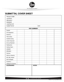
© Copyright 2026