
FUJI IGBT V-IPM APPLICATION MANUAL REH985 September 2012
FUJI IGBT V-IPM APPLICATION MANUAL September 2012 URL http: //www.fujielectric.co.jp/products/semiconductor/ REH985 CONTENTS Chapter 1 Features and structure 1. Features of IGBT-IPM ............................................................................1-2 2. Features of IPM by package ..................................................................1-3 3. Description of what are represented by type and lot number.................1-5 4. Line-up ...................................................................................................1-6 5. External appearances and dimensions drawing ....................................1-7 6. Structure...............................................................................................1-11 Chapter 2 Description of terminal marking and terms 1. Description of terminal marking..............................................................2-2 2. Description of terms ...............................................................................2-3 Chapter 3 Description of functions 1. List of functions ......................................................................................3-2 2. Description of functions..........................................................................3-4 3. Truth table ............................................................................................3-10 4. IPM block diagram ...............................................................................3-12 5. Timing chart..........................................................................................3-17 Chapter 4 Typical application circuits 1. Typical application circuits......................................................................4-2 2. Important points......................................................................................4-6 3. Photocoupler peripheral circuits .............................................................4-9 4. Connector.............................................................................................4-11 Chapter 5 Heat dissipation design 1. Method for selection of heat sink ...........................................................5-2 2. Important points for selection of a heat sink...........................................5-2 3. How to mount the IPM............................................................................5-3 Chapter 6 Precautions for use 1. Main power supply .................................................................................6-2 2. Control power supply .............................................................................6-3 3. Protective functions................................................................................6-4 4. Power Cycling Capability........................................................................6-5 5. Others ....................................................................................................6-6 Chapter 7 Troubleshooting 1. Troubleshooting......................................................................................7-2 2. Failure factor analysis charts..................................................................7-2 3. Alarm factor tree analysis chart..............................................................7-8 – Chapter 1 – Features and structure Table of Contents Page 1 Features of IGBT-IPM .......................... 1-2 2 Features of IPM by package .......................... 1-3 3 Description of what are represented by type and lot number .......................... 1-5 4 Line-up .......................... 1-6 5 External appearances and dimensions drawing .......................... 1-7 6 Structure .......................... 1-11 1-1 Chapter 1 Features and structure 1 Features of IGBT-IPM An IPM (intelligent power module) is an intelligent module mounting a control IC having a drive circuit and a protection circuit built in an IGBT module. It provides the following features: 1.1 Built-in drive circuit • Drives the IGBT under the optimally configured conditions. • The wiring length between the drive circuit and the IGBT is short and the drive circuit impedance is low. Therefore, no reverse bias power supply is needed. • The number of required control power supply units is one (1) on the lower arm side, three (3) on the upper arm side; total four (4) units. 1.2 Built-in protection circuit • Overcurrent protection (OC), short-circuit protection (SC), control power supply under voltage protection (UV), overheat protection (TjOH), and external output (ALM) of these alarms are incorporated. • OC and SC are functions to protect the IGBT against breakdown caused by overcurrent or load short-circuit. As these functions are implemented by detection of collector current by detecting elements built in each IGBT, they permit protection against disorder that occurs in any IGBT, and in addition, they are capable of protecting the IGBT against arm short-circuit. • UV is the protective function that works against drive power supply voltage drop, and it is built in every control IC. • TjOH provides a temperature detecting element on each IGBT chip, and the protection works at high speed against abnormal chip heat-up. • ALM is the function to output an alarm signal to outside, and it is possible to positively stop the system by sending an alarm signal to the microcomputer that controls the IPM on occurrence of protected operation of OC, SC, UV and/or TjOH. *1 *1 See [Chapter 3 Description of functions] for details of protective functions of each IPM. 1.3 Built-in brake circuit (7in1 IPM) • A brake circuit can be configured by adding a resistance that consumes electric power during deceleration. • A drive circuit and protection circuit are incorporated like in the inverter unit. 1.4 Conformity to RoHS directive • All types of V-IPM conform to RoHS directive. 1-2 Chapter 1 Features and structure 2 Features of IPM by package 2.1 Small-capacity type (mounting lower arm <only> alarm output function; 6in1) 600 V-series 20 A to 50 A and 1200 V-series 10 A to 25 A are lined up as small-capacity type. (P629 package) • P629 package products are of copper base type. They provide excellent heat dissipation performance. • Control input terminals are of 2.54 mm standard pitch. • Main terminals are of flat shape and are of the height same as that of control input terminals. Therefore, soldering connection on the same PCB is permitted. • Trade-off of the switching loss with Vce (sat) is improved by the application of 6th generation IGBT, and the total loss is reduced. • The chip is protected against abnormal heat-up by IGBT chip overheat protection. *1 • Detection is made by sense IGBT method for IGBT overcurrent protection. *1 • Mounting is compatible with that of R-IPM-series P619 package products. *1 Although the protective function is provided on the upper arm side, no alarm output function is available. 2.2 Medium-capacity small-size type (mounting upper and lower arm alarm output function; 6in1) 600V-series 50 A to 75 A and 1200 V-series 25 A to 50 A are lined up as medium-capacity small-size type. (P626 package) • Control input terminals are of 2.54 mm standard pitch. • Main terminals are of flat shape and are of the height same as that of control input terminals. Therefore, soldering connection on the same PCB is permitted. • Trade-off of the switching loss with Vce (sat) is improved by the application of 6th generation IGBT, and the total loss is reduced. • The chip is protected against abnormal heat-up by IGBT chip overheat protection. • Detection is made by sense IGBT method for IGBT overcurrent protection. 2.3 Medium-capacity thin type (mounting upper lower arm alarm output function, 6in1, 7in1) 600 V-series 50 A to 200 A and 1200 V-series 25 A to 100 A are lined up as medium-capacity thin type. (P630 package) • Control input terminals are of 2.54 mm standard pitch, and they can be connected using a general-purpose connector or by soldering. Insertion of a PCB connector is easy thanks to use of guide pins. • Main terminals are of M4 screw threads. 1-3 Chapter 1 Features and structure • The diameter of screws for mounting to the heat sink is M4, which is common with that of main terminals. • Electrical connection is entirely made by screws and connectors. No soldering is required and dismounting is easy. • Trade-off of the switching loss with Vce (sat) is improved by the application of 6th generation IGBT, and the total loss is reduced. • The chip is protected against abnormal heat-up by IGBT chip overheat protection. • Detection is made by sense IGBT method for IGBT overcurrent protection. 2.4 Large-capacity type (mounting upper lower arm alarm output function; 6in1, 7in1) 600 V-series 200 A to 400 A and 1200 V-series 100 A to 200 A are lined up as large-capacity type. (P631 package) • Main power supply input terminals (P1, P2, N1, N2), brake terminal (B) and output terminals (U, V, W) are located in proximity to each other, and the package structure permits easy main wiring. Terminals P1 and P2 and terminals N1 and N2 are connected inside. • Main terminals permit positive connection of large current by M5 screws. • The diameter of screws for mounting to the heat sink is M5, which is common with that of main terminals. • Electrical connection is entirely made by screws and connectors. No soldering is required and dismounting is easy. • Trade-off of the switching loss with Vce (sat) is improved by the application of 6th generation IGBT, and the total loss is reduced. • The chip is protected against abnormal heat-up by IGBT chip overheat protection. • Detection is made by sense IGBT method for IGBT overcurrent protection. • Mounting is compatible with that of R-IPM-series P612 package products (excluding control terminal portions). 1-4 Chapter 1 Features and structure 3 Description of what are represented by type and lot number • Type 6 MBP 50 V B A 060 -50 Model sequential number Voltage rating 060: 600 V 120: 1200 V Series sequential number Package A: P629 B: P626 D: P630 E: P631 Series name Current rating of inverter unit Represents “IGBT-IPM” Number of main elements 7: With built-in brake 8: Without brake • Lot number 2 1 0 0 0 Sequential number (001 to 999) Month of production 1: January ・ ・ ・ O: October N: November D: December Year of production 2: 2012 3: 2013 4: 2014 ・ ・ ・ • Label 6MBP50VBA060-50 50A 600V Lot No. Country of production and place of production Data matrix 1-5 Chapter 1 Features and structure 4 Line-up 600V-series Package Current rating 20A 30A 50A 75A 100A 150A 200A 300A 400A P629 P626 P630 6MBP20VAA060-50 6MBP30VAA060-50 6MBP50VAA060-50 - 6MBP50VBA060-50 6MBP75VBA060-50 - P629 P626 6MBP10VAA120-50 6MBP15VAA120-50 6MBP25VAA120-50 6MBP25VBA120-50 6MBP35VBA120-50 6MBP50VBA120-50 - P631 7/6MBP50VDA060-50 7/6MBP75VDA060-50 7/6MBP100VDA060-50 7/6MBP150VDA060-50 7/6MBP200VDA060-50 7/6MBP200VEA060-50 7/6MBP300VEA060-50 7/6MBP400VEA060-50 1200V-series Package Current rating 10A 15A 25A 35A 50A 75A 100A 150A 200A - P630 1-6 P631 7/6MBP25VDA120-50 7/6MBP35VDA120-50 7/6MBP50VDA120-50 7/6MBP75VDA120-50 7/6MBP100VDA120-50 7/6MBP100VEA120-50 7/6MBP150VEA120-50 7/6MBP200VEA120-50 Chapter 1 Features and structure 5 External appearances and dimensions drawing Note: 1. The dimension shown in 注) 1.□は理論寸法を示す。 represents the theoretical 2.端子ピッチは根元寸法とする。 dimension. 3.( )内寸法は、参考値とする。 2. The terminal pitch is the dimension measured4.端子: at the Sn-Cuメッキ root. (半田付け仕様) 3. Dimensions in ( ) are given for information only. [寸法:mm] 4. Terminals: Sn-Cu plating (soldering specification) [Unit of dimensions: mm] Figure 1-1 External appearances and dimensions drawing (P629) Target type: 6MBP20VAA060-50、6MBP30VAA060-50、6MBP50VAA060-50 6MBP10VAA120-50、6MBP15VAA120-50、6MBP25VAA120-50 1-7 Chapter 1 Features and structure Note: 1. The dimension shown in represents the theoretical dimension. 注) 1.□は理論寸法を示す。 2. 2.端子ピッチは根元寸法とする。 The terminal pitch is the dimension 3.端子: Sn-Cuメッキ measured at the root. (半田付け仕様) 3. Terminals: Sn-Cu plating (soldering [寸法:mm] specification) [Unit of dimensions: mm] Figure 1-2 External appearances and dimensions drawing (P626) Target type: 6MBP50VBA060-50、6MBP75VBA060-50 6MBP25VBA120-50、6MBP35VBA120-50、6MBP50VBA120-50 1-8 Chapter 1 Features and structure Note: 1. The dimension shown in represents the theoretical dimension. 2. The terminal pitch is the dimension measured at the root. 1.□は理論寸法を示す。 3.注) Dimensions in ( ) are given for information only. 2.端子ピッチは根元寸法とする。 4. Main terminals: Ni plating 3.( )内寸法は、参考値とする。 Control terminals: Ni plating on the ground, Au plating Niメッキ on4.主端子: the surface 制御端子:soldering 下地Ni+表面Auメッキ (connector, specification) (コネクタ、半田付け仕様) 5. The guide pins located on both sides of a control 5.制御端子両側にあるガイドピンは、黄銅(しんちゅう)です。 terminal are made of brass. (内部は、絶縁されており、どの部分にも接続されていません。) (They are insulated in the interior and are not connected to any object.) [寸法:mm] [Unit of dimensions: mm] Figure 1-3 External appearances and dimensions drawing (P630) Target type: 7/6MBP50VDA060-50、7/6MBP75VDA060-50、7/6MBP100VDA060-50、7/6MBP150VDA060-507/6MBP200VDA060-50、 7/6MBP25VDA120-50、7/6MBP35VDA120-50、7/6MBP50VDA120-50、7/6MBP75VDA120-50、7/6MBP100VDA120-50 1-9 Chapter 1 Features and structure 注) 1.□は理論寸法を示す。 The dimension shown in represents the theoretical dimension. 2.端子ピッチは根元寸法とする。 The terminal pitch is the dimension measured at the root. Dimensions in (3.( ))内寸法は、参考値とする。 are given for information only. Niメッキ Main terminals:4.主端子: Ni plating 制御端子: 下地Ni+表面Auメッキ Control terminals: Ni plating on the ground, Au plating on the surface (connector, soldering specification) (コネクタ、半田付け仕様) 5. The guide pins 5.制御端子両側にあるガイドピンは、黄銅(しんちゅう)です。 located on both sides of a control terminal are made of brass. (内部は、絶縁されており、どの部分にも接続されていません。) (They are insulated in the interior and are not connected to any object.) Note: 1. 2. 3. 4. [寸法:mm] [Unit of dimensions: mm] Figure 1-4 External appearances and dimensions drawing (P631) Target type: 7/6MBP200VEA060-50、7/6MBP300VEA060-50、7/6MBP400VEA060-50 7/6MBP100VEA120-50、7/6MBP150VEA120-50、7/6MBP200VEA120-50 1-10 Chapter 1 Features and structure 6 Structure * This drawing was prepared for explanation of the material. It does not represent accurate chip size or layout. No. Component name 1 2 3 4 Insulated substrate IGBT chip FWD chip Printed circuit board (PCB) 5 IC chip 6 Base 7 Main terminal 8 9 10 11 12 Cover Case Wire Gel Control terminal Material (main) Ceramics Silicone Silicone Glass epoxy Silicone Copper Copper Halogen-free Nickel plating Ground: Nickel plating Surface: Sn-Cu plating UL 94V-0 UL 94V-0 PPS resin PPS resin Aluminum Silicone resin Brass Figure 1-5 Remarks Ground: Nickel plating Surface: Sn-Cu plating Structure (P629) 1-11 Chapter 1 Features and structure * This drawing was prepared for explanation of the material. It does not represent accurate chip size or layout. No. Component name 1 2 3 4 Insulated substrate IGBT chip FWD chip Printed circuit board (PCB) 5 IC chip 6 Base 7 Main terminal 8 9 10 11 12 Cover Case Wire Gel Control terminal Material (main) Ceramics Silicone Silicone Glass epoxy Silicone Copper Copper Halogen-free Nickel plating Ground: Nickel plating Surface: Sn-Cu plating UL 94V-0 UL 94V-0 PPS resin PPS resin Aluminum Silicone resin Brass Figure 1-6 Remarks Ground: Nickel plating Surface: Sn-Cu plating Structure (P626) 1-12 Chapter 1 Features and structure * This drawing was prepared for explanation of the material. It does not represent accurate chip size or layout. No. 1 2 3 4 5 6 7 8 9 10 11 12 Component name Insulated substrate IGBT chip FWD chip Printed circuit board (PCB) IC chip Base Main terminal Cover Case Wire Gel Control terminal 13 Guide pin Material (main) Ceramics Silicone Silicone Glass epoxy Silicone Copper Copper PPS resin PPS resin Aluminum Silicone resin Brass Brass Figure 1-7 Structure (P630) 1-13 Remarks Halogen-free Nickel plating Surface: Nickel plating UL 94V-0 UL 94V-0 Ground: Nickel plating Surface: Au plating Chapter 1 Features and structure * This drawing was prepared for explanation of the material. It does not represent accurate chip size or layout. No. 1 2 3 4 5 6 7 8 9 10 11 12 Component name Insulated substrate IGBT chip FWD chip Printed circuit board (PCB) IC chip Base Main terminal Cover Case Wire Gel Control terminal 13 Guide pin Material (main) Ceramics Silicone Silicone Glass epoxy Silicone Copper Copper PPS resin PPS resin Aluminum Silicone resin Brass Remarks Halogen-free Nickel plating Surface: Nickel plating UL 94V-0 UL 94V-0 Ground: Nickel plating Surface: Au plating Brass Figure 1-8 Structure (P631) 1-14 Chapter 1 Features and structure • Main terminals of IPM (screw type) The structure of the main terminal unit is indicated below: Electrode Area A section Product Screw Main terminal A Nut Figure 1-9 Structure of main terminal unit of IPM (Example: P630) Table 1-1 Specification for IPM main terminal unit PKG Screw standard Main terminal thickness (B) Nut groove depth (C) Screw hole depth (D) P630 M4 0.8 3.5 8.5±0.5 P631 M5 1 4 9.0±0.5 [Unit: mm] • Guide pins of IPM The guide pins located on both sides of control terminal portions of P630 and P631 are made of brass. They are insulated in the interior and are not connected to any object. 1-15 – Chapter 2 – Description of terminal marking and terms Table of Contents Page 1 Description of terminal marking ............................................ 2-2 2 Description of terms ............................................ 2-3 2-1 Chapter 2 Description of terminal marking and terms 1 Description of terminal marking Main terminals Terminal marking Description Terminals for input of main power supply Vdc after smoothing with rectifying converter of the inverter unit P: + side, N: - side Brake input terminal: Terminal for input of resistance current for regenerative action during deceleration 3-phase inverter output terminals P (P1, P2) N (N1, N2) B U V W * P1, P2, N1, and N2 terminals are application to P631 package only. Control terminals Terminal P629 marking GND U ① Vcc U ③ Vin U ② P626 P630 ① ④ ③ P631 ① ③ ② ALM U - ② ④ GND V Vcc V Vin V ④ ⑥ ⑤ ⑤ ⑧ ⑦ ⑤ ⑦ ⑥ ALM V − ⑥ ⑧ GND W Vcc W Vin W ⑦ ⑨ ⑧ ⑨ ⑫ ⑪ ⑨ ⑪ ⑩ ALM W - ⑩ ⑫ GND Vcc Vin X Vin Y Vin Z Vin DB ⑩ ⑪ ⑫ ⑬ ⑭ - ⑬ ⑭ ⑯ ⑰ ⑱ ⑮ ⑬ ⑭ ⑯ ⑰ ⑱ ⑮ ALM ⑮ ⑲ ⑲ Description Control power supply Vcc input of upper arm U-phase Vcc U: + side, GND U: − side Control signal input of upper arm U-phase Alarm output of upper arm U-phase at the occasion of action of protection circuit Control power supply Vcc input of upper arm V-phase Vcc V: + side, GND V: − side Control signal input of upper arm V-phase Alarm output of upper arm V-phase at the occasion of action of protection circuit Control power supply Vcc input of upper arm W-phase Vcc W: + side, GND W: − side Control signal input of upper arm W-phase Alarm output of upper arm W-phase at the occasion of action of protection circuit Control power supply Vcc input of lower arm common Vcc: + side, GND: − side Control signal input of lower arm X-phase Control signal input of lower arm Y-phase Control signal input of lower arm Z-phase Control signal input of lower arm brake phase Alarm signal, "ALM" output of lower arm at the occasion of action of protection circuit * Pin (15) of P626 is of no contact. * Pin (15) of each of P631 (6in1), P630 (6in1) is of no contact. 2-2 Chapter 2 Description of terminal marking and terms 2 Description of terms 2.1 Absolute maximum rating Term Power supply voltage Power supply voltage (at the time of short-circuit) Voltage between collector and emitter Collector current Symbol Description DC power supply voltage that can be impressed between terminals PN VDC DC power supply voltage between terminals PN that can be protected against inVSC charge and overcurrent Maximum voltage between collector and emitter of the built-in IGBT chip and VCES repeated peak inverse voltage of the FWD chip (IGBT only for the brake unit) IC Maximum DC collector current allowed to the IGBT chip ICP Maximum pulse collector current allowed to the IGBT chip -IC Maximum DC forward current allowed to the FWD chip FWD forward current IF Maximum DC forward current allowed to the FWD chip in the brake unit Maximum value of electric power that can be consumed by one element of the Collector loss PC Loss with which Tj = 150°C at the time of Tc = 25°C Control power supply voltage VCC Voltage that can be impressed between terminals Vcc and GND Input voltage Vin Voltage that can be impressed between terminals Vin and GND Alarm impressed voltage VALM Voltage that can be impressed between terminals ALM and GND Alarm output current IALM Maximum value of the current that can be fed between terminals ALM and GND Maximum value of chip junction temperature that permits continuous action of Chip junction temperature Tj IGBT chip and FWD chip Case temperature at the time Case temperature range that permits electrical actions (Case temperature Tc Topr of action measuring point is shown in Figure 5-4.) Range of ambient temperature that permits storage or transportation without Storage temperature Tstg application of electrical load Solder temperature Tsol Maximum temperature at the time of soldering Maximum effective value of sine wave voltage that is permitted between terminals Viso Dielectric strength voltage and heat sink mounting surface with all the terminals shunted. Maximum torque at the occasion of connection of external wiring to a terminal Tightening torque Terminal using a specified screw Maximum torque at the occasion of mounting of an element to a heat sink using a Mounting specified screw 2.2 2.2.1 Electrical characteristics Main circuit Term Interrupting current between collector and emitter Symbol ICES Saturated voltage between collector and emitter VCE (sat) Diode forward voltage VF Turn-on time ton Turn-off time toff Deactivation time tf Reverse recovery time trr Dead time tdead Description Leak current at the time of impression of specified voltage between collector and emitter of the IGBT with full input signal H Voltage between collector and emitter at the time of feed of collector current in the state where the input signal only of the measurement target element is L (= 0 V) and the input to all of other elements is H Forward voltage at the time of current feed to the diode with full input signal H Length of time before the collector current rises to 90% or greater of the required current since the input signal became lower than input threshold voltage Vinth (on). Shown in Figure 2-1. Length of time before the collector current drops to 10% or less of the required current along the reducing tangential line since the input signal became higher than input threshold voltage Vinth (off). Shown in Figure 2-1. Length of time before the collector current drops to 10% or less along the reducing tangential line from 90% of the required current at the time of IGBT turn-off. Shown in Figure 2-1. Length of time before the reverse recovery current of the built-in diode disappears along the reducing tangential line. Shown in Figure 2-1. Upper/lower arm input signal pause time. Shown in Figure 2-5. 2-3 Chapter 2 Description of terminal marking and terms 2.2.2 Control circuit Term Control power supply consumption current Input threshold voltage 2.2.3 Symbol Iccp Iccn Vinth (on) Vinth (off) Description Current that flows between upper arm side control power supply Vcc and GND Current that flows between lower arm side control power supply Vcc and GND Voltage that permits the control IC to identify the input voltage as an ON signal Voltage that permits the control IC to identify the input voltage as an OFF signal Protection circuit Term Overcurrent protected Overcurrent interruption lag time Short-circuit protected Symbol Description Ioc IGBT collector current with which overcurrent protected (OC) operation occurs Lag time since overcurrent protection trip until protection begins. Shown in Figure tdoc 2-3. Isc IGBT collector current with which short-circuit protected (SC) operation occurs Lag time since short-circuit protection trip until protection begins. Shown in Figure Short-circuit protection lag time tsc 2-4. Chip overheat protection Trip temperature at which IGBT is shutoff due to overheat of IGBT chip junction TjOH temperature temperature Tj Chip overheat protection Temperature drop required before reset of output stop after protected operation TjH hysteresis Control power supply under Trip voltage at which soft shutoff of IGBT occurs due to drop in control power VUV voltage protection voltage supply voltage Vcc Control power supply under Reset voltage required before reset of output stop after protected operation VH voltage protection hysteresis tALM (OC) Alarm signal output pulse width produced by overcurrent protected (OC) operation Alarm signal output pulse width produced by control power supply under voltage Alarm output hold time tALM (UV) protection (UV) operation tALM (TjOH) Alarm signal output pulse width produced by chip overheat protected (TjOH) Value of built-in resistance that is connected in series to alarm terminals Alarm output resistance RALM It limits the photocoupler primary side forward current. 2.3 Thermal characteristics Term Thermal resistance between chip and case Thermal resistance between case and fin Case temperature 2.4 Description Rth (c-f) Tc Thermal resistance between case and heat sink in the state of being mounted to the heat sink with recommended torque value using thermal compound IPM case temperature (temperature of copper base bottom face just below IGBT or diode) Noise tolerance Term Common mode 2.5 Symbol Rth (j-c) Q Thermal resistance between chip and case of IGBT Rth (j-c) D Thermal resistance between chip and case of diode Symbol Description Common mode noise tolerance in our test circuit − Others Term Mass Switching frequency Reverse recovery current Reverse bias safe operation area Switching loss Inverse voltage Input current Symbol Description Wt Mass of unit IPM fsw Control signal frequency range that can be input to control signal input terminals Irr Peak value of reverse recovery current. Shown in Figure 2-1. Area of current and voltage that permit IGBT shutoff under specified conditions at RBSOA the time of turn-off. There is a possibility where the element is broken if used outside of this area. Eon IGBT switching loss at the time of turn-on Eoff IGBT switching loss at the time of turn-off Err FWD switching loss at the time of reverse recovery VR Repeated peak inverse voltage of FRD chip in the brake unit Iin Maximum value of the current that can be fed to Vin-GND terminals 2-4 Chapter 2 Description of terminal marking and terms Vinth(off) Vinth(on) off on Input signal trr Irr 90% 90% Collector current tf ton toff Figure 2-1 Switching time With protection factor Protection factor High Without protection factor tALM VALM Low OFF High Vin Low ON IC IGBT guard state Protected period Figure 2-2 Alarm output hold time (tALM) 2-5 10% Chapter 2 Description of terminal marking and terms off Input signal on IOC Collector current Alarm output ① Figure 2-3 ② < tdoc Overcurrent interruption lag time (tdoc) tSC Isc IC VALM Figure 2-4 Short-circuit protection lag time (tsc) 2-6 alarm ≧tdoc Chapter 2 Description of terminal marking and terms Vin Vinth(off) Turn-off side ターンオフ側 Ic Vin tdead Vinth(on) Turn-on side ターンオン側 Ic Figure 2-5 Dead time 2-7 – Chapter 3 – Description of functions Table of Contents Page 1 List of functions ............................................ 3-2 2 Description of functions ............................................ 3-4 3 Truth table ............................................ 3-10 4 IPM block diagram ............................................ 3-12 5 Timing chart ............................................ 3-17 3-1 Chapter 3 Description of functions 1 List of functions The functions incorporated in V-IPM are shown in Tables 3-1 and 3-2. Table 3-1 IPM built-in functions, 600 V-series Number of elements 6 in 1 7 in 1 Type 6MBP20VAA060-50 6MBP30VAA060-50 6MBP50VAA060-50 6MBP50VBA060-50 6MBP75VBA060-50 6MBP50VDA060-50 6MBP75VDA060-50 6MBP100VDA060-50 6MBP150VDA060-50 6MBP200VDA060-50 6MBP200VEA060-50 6MBP300VEA060-50 6MBP400VEA060-50 7MBP50VDA060-50 7MBP75VDA060-50 7MBP100VDA060-50 7MBP150VDA060-50 7MBP200VDA060-50 7MBP200VEA060-50 7MBP300VEA060-50 7MBP400VEA060-50 Built-in function Common to upper and lower Upper arms arm Drive UV TjOH OC / SC ALM ○ – ○ ○ ○ ○ – ○ ○ ○ ○ – ○ ○ ○ ○ ○ ○ ○ ○ ○ ○ ○ ○ ○ ○ ○ ○ ○ ○ ○ ○ ○ ○ ○ ○ ○ ○ ○ ○ ○ ○ ○ ○ ○ ○ ○ ○ ○ ○ ○ ○ ○ ○ ○ ○ ○ ○ ○ ○ ○ ○ ○ ○ ○ ○ ○ ○ ○ ○ ○ ○ ○ ○ ○ ○ ○ ○ ○ ○ ○ ○ ○ ○ ○ ○ ○ ○ ○ ○ ○ ○ ○ ○ ○ ○ ○ ○ ○ ○ ○ ○ ○ ○ ○ Lower arm ALM ○ ○ ○ ○ ○ ○ ○ ○ ○ ○ ○ ○ ○ ○ ○ ○ ○ ○ ○ ○ ○ Package P629 P626 P630 P631 P630 P631 Drive: IGBT drive circuit, UV: Control power supply under voltage protection, TjOH: Chip temperature overheat protection, OC: Overcurrent protection, SC: Short-circuit protection, ALM: Alarm signal output 3-2 Chapter 3 Description of functions Table 3-2 IPM built-in functions, 1200 V-series Number of elements 6 in 1 7 in 1 Type 6MBP10VAA120-50 6MBP15VAA120-50 6MBP25VAA120-50 6MBP25VBA120-50 6MBP35VBA120-50 6MBP50VBA120-50 6MBP25VDA120-50 6MBP35VDA120-50 6MBP50VDA120-50 6MBP75VDA120-50 6MBP100VDA120-50 6MBP100VEA120-50 6MBP150VEA120-50 6MBP200VEA120-50 7MBP25VDA120-50 7MBP35VDA120-50 7MBP50VDA120-50 7MBP75VDA120-50 7MBP100VDA120-50 7MBP100VEA120-50 7MBP150VEA120-50 7MBP200VEA120-50 Built-in function Common to upper and lower Upper arms arm Drive UV TjOH OC / SC ALM ○ ○ ○ ○ ○ ○ ○ ○ ○ ○ ○ ○ ○ ○ ○ ○ ○ ○ ○ ○ ○ ○ ○ ○ ○ ○ ○ ○ ○ ○ ○ ○ ○ ○ ○ ○ ○ ○ ○ ○ ○ ○ ○ ○ ○ ○ ○ ○ ○ ○ ○ ○ ○ ○ ○ ○ ○ ○ ○ ○ ○ ○ ○ ○ ○ ○ ○ ○ ○ ○ ○ ○ ○ ○ ○ ○ ○ ○ ○ ○ ○ ○ ○ ○ ○ ○ ○ ○ ○ ○ ○ ○ ○ ○ ○ ○ ○ ○ ○ ○ ○ ○ ○ ○ ○ ○ ○ Lower arm ALM ○ ○ ○ ○ ○ ○ ○ ○ ○ ○ ○ ○ ○ ○ ○ ○ ○ ○ ○ ○ ○ ○ Package P629 P626 P630 P631 P630 P631 Drive: IGBT drive circuit, UV: Control power supply under voltage protection, TjOH: Chip temperature overheat protection, OC: Overcurrent protection, SC: Short-circuit protection, ALM: Alarm signal output 3-3 Chapter 3 Description of functions 2 Description of functions 2.1 IGBT and FWD for 3-phase inverter IGBT and FWD for 3-phase inverter are incorporated and a 3-phase bridge circuit is configured in IPM as shown in Figure 3-1. The main wiring is completed when the main power supply line is connected to terminals P and N and the 3-phase output line is connected to terminals U, V and W. Connect and use a snubber circuit to suppress the surge voltage. 2.2 IGBT and FWD for brake IGBT and FWD for brake are incorporated and the collector electrode of IGBT is output to outside as terminal B as shown in Figure 3-1. If the brake IGBT is controlled by connecting a brake resistance between terminals P and B, the regenerative energy during deceleration is consumed and voltage rise between terminals P and N can be suppressed. P-side PWM input Alarm output Alarm output Alarm output IPM Pre-Driver Pre-Driver Pre-Driver P B U V W N Pre-Driver Pre-Driver Brake input Figure 3-1 Pre-Driver N-side PWM input Pre-Driver Alarm output Typical application of 3-phase inverter (Example: 7MBP200VDA060-50 with built-in brake) 3-4 Chapter 3 Description of functions 2.3 IGBT drive function Figure 3-2 shows a block diagram of the Pre-Driver. As the IPM incorporates the function to drive the IGBT, when the photocoupler output is connected to the IPM, it is possible to drive the IGBT without designing the gate resistance value. The features of this drive function are introduced below: Independent gate output control A drive circuit dedicated to turn-on and turn-off is incorporated without using a single gate resistance. As this arrangement permits independent control of dv/dt of turn-on and turn-off, it is possible to fully exhibit characteristics of the elements. Soft shutoff The gate voltage is gradually reduced at the occasion of IGBT shutoff by protected operation in a disorder mode of various kinds, generation of surge voltage that accompanies IGBT shutoff is suppressed, and thus breakdown of elements caused by the surge voltage is prevented. Erroneous ON prevention As a circuit that grounds the gate electrode of the IGBT to the emitter at low impedance is provided, erroneous ON caused by rise of VGE due to noise or similar at the occasion of turn-off is prevented. No necessity of reverse bias power supply As the IPM is of short wiring between the control IC and the IGBT, the wiring impedance is small and the IPM can be driven without reverse bias. 3-5 Chapter 3 Description of functions VCC VCC IN OUT VCC AE AER PGND OC VCC VCC OH ロジック回路 SGND VCC Figure 3-2 2.4 Pre-Driver block diagram (Example: 7MBP200VDA060-50) Protective functions The IPM incorporates a protection circuit and protects the IPM against the disorder mode that causes element breakdown. Protective functions of four kinds work in correspondence to factors for disorder modes. Disorder modes are OC (overcurrent protection), SC (short-circuit protection), UV (control power supply under voltage protection) and TjOH (chip temperature overheat protection). When a protective function works, the alarm output MOS is ON, and the alarm output terminal voltage changes from High to Low, and the alarm output terminal becomes conductive to each reference potential GND. Furthermore, since a 1.3 KΩ resistance is connected in series between the control IC and the alarm output terminal, the photocoupler that is connected between the ALM terminal and the Vcc terminal can be driven directly. Alarm signal output function During the protected operation period, the IGBT does not operate even when an ON signal is input. Soft shutoff of the IGBT is applied upon identification of a disorder mode, and alarm signal output can be made from the phase that detected a disorder mode. • If the alarm signal output period (tALM) or longer has elapsed, the alarm factor has been dissolved and the input signal is OFF, then the protected operation is cancelled and normal operation is resumed. 3-6 Chapter 3 Description of functions • Even in case the alarm factor was dissolved during the alarm signal output period (tALM), protected operation continues during the alarm signal output period (tALM), and accordingly, the IGBT does not operate. If the input signal is OFF after elapse of the alarm signal output period (tALM), then the protected operation is cancelled and normal operation is resumed. Furthermore, mutual inter-alarm connection is made for each phase including brake on the lower arm side. When protected operation occurs on the lower arm side, therefore, soft shutoff is applied to all the IGBTs of the lower arm during the protected operation period, and the operation stops. * P629 package incorporates protective functions on the upper arm side, but it does not incorporate the alarm signal output function. For the lower phase, both of protective functions and alarm signal output function are incorporated. Alarm factor identification function As the alarm signal output period (tALM) varies in correspondence to the disorder mode, disorder mode factor identification can be implemented on the device side by using the output alarm signal pulse width. Alarm factor Alarm signal output period (tALM) Overcurrent protection (OC) 2 ms (typ.) Short-circuit protection (SC) Control power supply under 4 ms (typ.) voltage protection (UV) Chip temperature overheat 8 ms (typ.) protection (TjOH) However, the alarm signal output time on the alarming photocoupler secondary side varies by the influence of photocoupler lag time and peripheral circuits. It is necessary to take into account this influence in the design. 3-7 Chapter 3 Description of functions 2.5 Overcurrent protection function: Over Current (OC) The IGBT’s forward collector current is detected by fetching the sense current, which flows to the current sense IGBT built in the IGBT chip, to the control circuit. When current of the set current protection level (IOC) or higher flows continuously for a period of about 5 µs (tdOC), it is judged as being in the OC status and soft shutoff is applied to the IGBT for preventing occurrence of breakdown by overcurrent. When it is judged as being in the OC status, protective functions and alarm signal output function operate. The OC status alarm signal output period (tALM) is about 2 ms. • Protected operation is cancelled and normal operation is resumed, if the current level is lower than the IOC level and the input signal is OFF about 2 ms (tALM) after alarm signal output. • Even in case the alarm factor was dissolved in about 2 ms (tALM), protected operation continues until the period of about 2 ms (tALM) elapses, and accordingly, the IGBT does not operate. If the input signal is OFF after elapse of about 2 ms (tALM), then the protected operation is cancelled and normal operation is resumed. 2.6 Short-circuit protective function: Short Circuit (SC) The SC protective function suppresses the peak current during load short-circuit and arm short-circuit. The IGBT’s forward collector current is detected, and when current of the set current protection level (ISC) or higher flows continuously for a period of tdsc, it is judged as being in the SC status and soft shutoff is applied to the IGBT for preventing occurrence of breakdown by short-circuit. When it is judged as being in the SC status, protective functions and alarm signal output function operate. The SC status alarm signal output period (tALM) is about 2 ms. • Protected operation is cancelled and normal operation is resumed, if the current level is lower than the ISC level and the input signal is OFF about 2 ms (tALM) after alarm signal output. • Even in case the alarm factor was dissolved in about 2 ms (tALM), protected operation continues until the period of about 2 ms (tALM) elapses, and accordingly, the IGBT does not operate. If the input signal is OFF after elapse of about 2 ms (tALM), then the protected operation is cancelled and normal operation is resumed. 2.7 Control power supply under voltage protection function (UV) The UV protective function prevents malfunction of the control IC caused by a drop in the control power supply voltage (VCC) and thermal breakdown of the IGBT caused by increase of the VCE (sat) loss. When VCC is continuously less than the set voltage protection level (VUV) for a period of about 20 µs, it is judged as being in the UV status and soft shutoff is applied to the IGBT to prevent malfunction and breakdown caused by control power supply voltage drop. When it is judged as being in the UV status, protective functions and alarm signal output function operate. The alarm signal output period (tALM) of the UV status is about 4 ms. 3-8 Chapter 3 Description of functions • As hysteresis VH is provided, protected operation is cancelled and normal operation is resumed, if VCC is higher than VUV + VH and the input signal is OFF about 4 ms (tALM) after output of an alarm signal. • Even in case the alarm factor was dissolved in about 4 ms (tALM), protected operation continues until the period of about 4 ms (tALM) elapses, and accordingly, the IGBT does not operate. If the input signal is OFF after elapse of about 4 ms (tALM), then the protected operation is cancelled and normal operation is resumed. Furthermore, an alarm signal for judgment of the UV status is output at the time of activation and deactivation of control power supply voltage VCC. 2.8 chip temperature overheat protective function: IGBT chip Over Heat protection (TjOH) The TjOH protective function directly detects the IGBT chip temperature by a temperature detecting element built in every IGBT chip. If the IGBT chip temperature was continuously higher than protection level (TjOH) for about 1.0 ms, it is judged as being in the overheat status, soft shutoff is applied to the IGBT and element breakdown is prevented by the TjOH protective function. When it is judged as being in the TjOH status, protective functions and alarm signal output function operate. The UV status alarm signal output period (tALM) is about 8 ms. • As hysteresis TjH is provided, protected operation is cancelled and normal operation is resumed, if Tj is less than TjOH-TjH and the input signal is OFF about 8 ms (tALM) after output of an alarm signal. • Even in case the alarm factor was dissolved in about 8 ms (tALM), protected operation continues until the period of about 8 ms (tALM) elapses, and accordingly, the IGBT does not operate. If the input signal is OFF after elapse of about 8 ms (tALM), then the protected operation is cancelled and normal operation is resumed. In addition, the case temperature overheat protective function (TCOH), which was built in the former series, is not built in this V-series. The IGBT chip overheat status can be protected by the TjOH protective function. 3-9 Chapter 3 Description of functions 3 Truth table The truth table at the time of trouble outbreak is shown in Tables 3-3 to 3-5. Table 3-3 Truth table (P629) IGBT Alarm factor U-phase V-phase W-phase Lower arm side X, Y and Zphase V-phase * * * * OFF OFF OFF OFF * * * * * * * * U-phase OFF OFF OFF OFF * * * * * * * * * * * * OC SC UV TjOH OC SC UV TjOH OC SC UV TjOH OC SC UV TjOH Alarm signal output W-phase * * * * * * * * OFF OFF OFF OFF * * * * Lower arm side * * * * * * * * * * * * OFF OFF OFF OFF ALM-Low side High High High High High High High High High High High High Low Low Low Low * Dependent on the input signal. Table 3-4 Truth table (P626) IGBT Alarm factor U-phase V-phase W-phase Lower arm side X, Y and Zphase OC SC UV TjOH OC SC UV TjOH OC SC UV TjOH OC SC UV TjOH U-phase V-phase OFF OFF OFF OFF * * * * * * * * * * * * * * * * OFF OFF OFF OFF * * * * * * * * Alarm signal output Lower arm W-phase side * * * * * * * * * * * * * * * * OFF * OFF * OFF * OFF * * OFF * OFF * OFF * OFF * Dependent on the input signal. 3-10 ALM-U ALM-V ALM-W Low Low Low Low High High High High High High High High High High High High High High High High Low Low Low Low High High High High High High High High High High High High High High High High Low Low Low Low High High High High ALM-Low side High High High High High High High High High High High High Low Low Low Low Chapter 3 Description of functions Table 3-5 Truth table (P630 and P631) IGBT Alarm factor U-phase V-phase W-phase Lower arm side X, Y and Zphase OC SC UV TjOH OC SC UV TjOH OC SC UV TjOH OC SC UV TjOH Alarm signal output Lower arm U-phase V-phase W-phase side OFF * * * OFF * * * * * OFF * * * OFF * OFF * * * * OFF * * * OFF * * * OFF * * * * OFF * * OFF * * * OFF * * OFF * * * * * * OFF * * * OFF * * * OFF * * * OFF * Dependent on the input signal. 3-11 ALM-U ALM-V ALM-W Low Low Low Low High High High High High High High High High High High High High High High High Low Low Low Low High High High High High High High High High High High High High High High High Low Low Low Low High High High High ALM-Low side High High High High High High High High High High High High Low Low Low Low Chapter 3 Description of functions 4 IPM block diagram IPM block diagrams are shown in Figures 3-3 to 3-8. P VccU ③ VinU ② Pre-Driver U GNDU ① VccV ⑥ VinV ⑤ Pre-Driver V GNDV ④ VccW ⑨ VinW ⑧ Pre-Driver W GNDW ⑦ Vcc ⑪ VinX ⑫ VinY ⑬ Pre-Driver VinZ ⑭ GND ⑩ ALM ⑮ N RALM Figure 3-3 IPM block diagram (P629) 3-12 Chapter 3 Description of functions P VccU ④ VinU ③ ALMU ② Pre-Driver RALM U GNDU ① VccV ⑧ VinV ⑦ ALM V ⑥ Pre-Driver RALM GNDV ⑤ V VccW ⑫ VinW ⑪ ALM W ⑩ Pre-Driver RALM GNDW ⑨ W Vcc ⑭ VinX ⑯ Pre-Driver GND ⑬ VinY ⑰ Pre-Driver VinZ ⑱ Pre-Driver ⑮ ALM ⑲ N RALM Figure 3-4 IPM block diagram (P626) 3-13 Chapter 3 Description of functions P VccU ④ VinU ③ ALMU ② Pre-Driver RALM GNDU ① U VccV ⑧ VinV ⑦ ALM V ⑥ Pre-Driver RALM GNDV ⑤ V VccW ⑫ VinW ⑪ ALM W ⑩ Pre-Driver RALM GNDW ⑨ W Vcc ⑭ VinX ⑯ Pre-Driver GND ⑬ VinY ⑰ Pre-Driver B VinZ ⑱ Pre-Driver ⑮ ALM ⑲ N RALM Figure 3-5 IPM block diagram (P630 without break) 3-14 Chapter 3 Description of functions VccU ④ P VinU ③ ALMU ② Pre-Driver RALM U GNDU ① VccV ⑧ VinV ⑦ ALM V ⑥ Pre-Driver RALM V GNDV ⑤ VccW ⑫ VinW ⑪ ALM W ⑩ Pre-Driver RALM W GNDW ⑨ Vcc ⑭ VinX ⑯ Pre-Driver GND ⑬ VinY ⑰ Pre-Driver VinZ ⑱ Pre-Driver B VinDB ⑮ ALM ⑲ Pre-Driver N RALM Figure 3-6 IPM block diagram 3-15 (P630 with built-in brake) Chapter 3 Description of functions VCCU ③ P1 VinU ② ALMU ④ Pre-Driver P2 RALM U GNDU ① VCCV ⑦ VinV ⑥ ALM V ⑧ Pre-Driver RALM GNDV ⑤ V VCCW ⑪ VinW ⑩ ALM W ⑫ Pre-Driver RALM W GNDW ⑨ VCC ⑭ VinX ⑯ Pre-Driver GND ⑬ VinY ⑰ Pre-Driver VinZ ⑱ Pre-Driver B ⑮ N1 ALM ⑲ N2 RALM Figure 3-7 IPM block diagram (P631 without brake) 3-16 Chapter 3 Description of functions VCCU ③ P1 VinU ② ALMU ④ Pre-Driver P2 RALM GNDU ① U VCCV ⑦ VinV ⑥ ALM V ⑧ Pre-Driver RALM GNDV ⑤ V VCCW ⑪ VinW ⑩ ALM W ⑫ Pre-Driver RALM W GNDW ⑨ VCC ⑭ VinX ⑯ Pre-Driver GND ⑬ VinY ⑰ Pre-Driver VinZ ⑱ Pre-Driver B VinDB ⑮ Pre-Driver N1 ALM ⑲ N2 RALM Figure 3-8 IPM block diagram (P631 with built-in brake) 3-17 Chapter 3 Description of functions 5 Timing chart 5.1 Control power supply under voltage protection (UV), Case 1 VUV+VH VUV VCC 5V 20 μs > 20 μs > High (OFF) Vin Low (ON) IC In operation Protected peration Cancelled High 20 μs VALM *2 20 μs 20 μs 20 μs Low tALM (UV) (1) *1 tALM (UV) (2) (3) (4) tALM (UV) (5) (6) (7) < tALM (UV) (8) *1: tALM (UV) is 4 ms, typical. *2: Dead time 20 μs is a typical (1) At the time of VCC close, alarm output begins if VCC is 5 V or higher and is VUV or less. (See 5.3 for details.) (2) Protected operation is not performed, if the length of time during which VCC was VUV or less is shorter than 20 µs. (While Vin is off) (3) While Vin is off, an alarm is output about 20 µs after VCC dropped to VUV or less, and the IGBT is kept in the off status. (4) UV protected operation continues during the tALM (UV) period, even if VCC returns to VUV + VH before elapse of tALM (UV) and even if Vin is off. Reset from protected operation occurs on termination of the tALM (UV) period. (5) Protected operation is not performed, if the length of time during which VCC was VUV or less is shorter 3-18 Chapter 3 Description of functions than 20 µs. (While Vin is on) (6) While Vin is on, an alarm is output about 20 µs after VCC dropped to VUV or less, and soft shutoff is applied to the IGBT. (7) In case VCC returns to VUV + VH before elapse of the tALM (UV) period and Vin on is continued, an alarm is output during the tALM (UV) period, but protected operation is also held thereafter. Reset from protected operation occurs when Vin is off. (8) An alarm is output at VUV or less while VCC is shutoff. (See 5.3 for details.) 5.2 Control power supply under voltage protection (UV), Case 2 VUV+VH VUV VCC 5V High (OFF) Vin Low (ON) IC In operation rotected peration Cancelled High 20 μs VALM 20 μs *2 20 μs 20 μs Low tALM (UV) *1 tALM (UV) (1) (2) tALM (UV) < tALM (UV (3) *1: tALM (UV) is 4 ms, typical. *2: Dead time 20 μs is a typical (1) At the time of VCC close, an alarm is output and Vin is kept in the on status. Therefore, UV protected operation is held regardless of VCC voltage drop. (2) Reset from protected operation occurs at the timing when Vin is off in the state where VCC is VUV+VH or higher. (3) As VCC is VUV or less, protected operation is continued without depending on the Vin signal, and the IGBT is not on. In addition, even if duration of the protected operation is sufficiently longer than tALM (UV), alarm output occurs only once. 3-19 Chapter 3 Description of functions 5.3 Control power supply under voltage protection (UV) at the time of power on and power off V-IPM is provided with the control power supply under voltage protection (UV) function. Because of this reason, it outputs an alarm at the time of power on and also at the time of power off. Its details are described below: 5.3.1 At the time of power on When VCC exceeds 5 V, an alarm is output VUV+V VUV after elapse of 20 μs in both of Case 1 and VCC High (OFF) (UV) is in the off status. In Case 2, protected operation continues even after alarm output (UV). Vin Low (ON) Low (ON) In operation In operation Protected operation because VCC is VUV+VH or less even after 5V High (OFF) Vin because VCC is higher than VUV + VH and Vin elapse of tALM VCC 5V Case 2. In Case 1, reset from protected operation occurs after elapse of tALM VUV+VH VUV Protected operation Cancelled Cancelled Reset from protected High operation occurs when VCC exceeds VUV + VALM VH and Vin is off. High 20 μs 20 μs VALM Low Low tALM (UV) tALM (UV) Case 1 Case 2 5.3.2 At the time of power off When VCC becomes less than VUV, an alarm is output after elapse of 20 μs VUV+VH VUV VCC 5V in both of Case 3 and Case 4. In Case 3, IPM operation becomes unstable and the alarm is cancelled because VCC continues because VCC is higher than VCC 5V High (OFF) Vin High (OFF) Vin Low (ON) becomes less than 5V before elapse of tALM (UV). In Case 4, protected operation VUV+VH VUV In operation Low (ON) In operation Protected operation Protected operation Cancelled Cancelled 5 V even after elapse of tALM (UV). At the time when VCC becomes less than 5 V, protected operation of the control IC is High VALM VALM 20 μs disabled and VALM changes to VCC equivalent. High Low < tALM (UV) Case 3 3-20 20 μs Low tALM (UV) Case 4 Chapter 3 Description of functions 5.4 Overcurrent protection (OC) High (OFF) Vin Low (ON) IOC IC In operation Protected operation Cancelled High VALM tdOC Low tdOC > tdOC tdOC > *2 tALM (OC) tALM (OC) *1 (1) (2) (3) (4) (5) *1: tALM (OC) is 2 ms, typical. *2: tdOC is 5 μs, typical. (1) An alarm is output upon elapse of tdOC after IC exceeded IOC, and soft shutoff is applied to the IGBT. (2) Even if Vin is off before elapse of tALM (OC), protected operation continues during the tALM (OC) period, and reset from protected operation occurs if Vin is off after elapse of tALM (OC). (3) OC protected operation continues if Vin is on after elapse of tALM (OC), and reset from protected operation occurs when Vin is off. In addition, even if duration of the protected operation is sufficiently longer than tALM (OC), alarm output occurs only once. (4) When Vin is off before elapse of tdOC since IC exceeded IOC, protected operation is not performed and normal shutoff is applied to the IGBT. (5) Even if IC is higher than IOC at the timing of Vin on, protected operation is not performed and normal shutoff is applied to the IGBT, if Vin is off before elapse of tdOC. 3-21 Chapter 3 Description of functions 5.5 Short-circuit protection (SC) High (OFF) Vin Low (ON) ISC IOC IC In operation Protected operation Cancelled High VALM tSC Low tSC tSC > tSC > *2 tALM (OC) tALM (OC) *1 (1) (2) (3) (4) (5) *1: tALM (OC) is 2 ms, typical. *2: tSC is 2 μs, typical. (1) Load short-circuit arises immediately after IC began to flow, and the IC peak is suppressed momentarily when ISC is exceeded. After elapse of tSC, an alarm is output and soft shutoff is applied to the IGBT. (2) SC protected operation and alarm are reset simultaneously if Vin is off after elapse of tALM (OC). (3) Load short-circuit arises immediately after IC began to flow, and the IC peak is suppressed momentarily when ISC is exceeded. After elapse of tSC, an alarm is output and soft shutoff is applied to the IGBT. (4) SC protected operation continues if Vin is on even after elapse of tALM (OC). SC protected operation is cancelled when a Vin off signal is input. In addition, even if duration of the protected operation until Vin is off is sufficiently longer than tALM (OC), alarm output occurs only once. (5) Load short-circuit arises immediately after IC began to flow, and the IC peak is suppressed momentarily when ISC is exceeded. If Vin is off before elapse of tSC thereafter, SC protected operation is not performed and normal shutoff is applied to the IGBT. (6) Load short-circuit arises immediately after IC began to flow, and the IC peak is suppressed momentarily when ISC is exceeded. If Vin is off before elapse of tSC thereafter, SC protected operation is not performed and normal shutoff is applied to the IGBT. 3-22 Chapter 3 Description of functions 5.6 Chip temperature heating protection (TjOH), Case 1 High (OFF) Vin Low (ON) TjOH TjOH-TjH Tj IC In operation Protected operation Cancelled High VALM 1 ms Low 1 ms 1 ms *2 tALM(TjOH) (1) *1 tALM(TjOH) (2) tALM(TjOH) (3) (4) *1: tALM (TjOH) is 8 ms, typical. *2: Dead time 1 ms is a typical value. (1) An alarm is output and soft shutoff is applied to the IGBT, if chip temperature Tj is in excess of TjOH continuously for about 1 ms. (2) Protected operation continues during the tALM (TjOH) period even if IGBT chip temperature Tj drops to TjOH-TjH or less before the tALM (TjOH) period elapses. Reset from protected operation occurs, if Vin is on after elapse of the tALM (TjOH) period. (3) Reset from protected operation does not occur, even Vin on is continued, even if chip temperature Tj has dropped to TjOH-TjH or less after elapse of the tALM (TjOH) period. (4) Protected operation continues after elapse of the tALM (TjOH) period, if chip temperature Tj is TjOH-TjH or higher, even if Vin is off. In addition, even if duration of the protected operation is sufficiently longer than tALM (TjOH), alarm output occurs only once. 3-23 Chapter 3 Description of functions 5.7 Chip temperature heating protection (TjOH), Case 2 High (OFF) Vin Low (ON) TjOH TjOH-TjH Tj 1 ms > 1 ms > 2.5 μs < IC In operation Protected operation Cancelled High VALM 1 ms Low 1 ms *2 tALM (TjOH) *1 tALM (TjOH) (1) (2) (3) *1: tALM (TjOH) is 8 ms, typical. *2: Dead time 1 ms is a typical value. (1) Protected operation does not occur if Tj drops to TjOH or less in a period that is less than about 1 ms after it exceeded TjOH, regardless of whether Vin is on or off. (2) Protected operation does not occur if Tj drops to TjOH or less in a period that is less than about 1 ms after it exceeded TjOH, regardless of whether Vin is on or off. (3) The TjOH detection timer of about 1 ms is reset if Tj has been kept at TjOH-TjH or less for a period of about 2.5 µs or longer after it exceeded TjOH. 3-24 Chapter 3 Description of functions 5.8 Case where protective functions operated compositely TjOH TjOH-TjH Tj VUV+VH VUV VCC IC High (OFF) Vin Low (ON) In operation Protected operation Cancelled High VALM 1 ms Low 1 ms 20 μs *3 *4 tALM (TjOH) (1) (2) *1 tALM (TjOH) (3) tALM (UV) (4) (5) (6) *1: tALM (TjOH) is 8 ms, typical. *2: tALM (UV) is 4 ms, typical. *2 (7) *3: Dead time 1 ms is a typical value. *4: Dead time 20 μs is a typical value. (1) An alarm is output and soft shutoff is applied to the IGBT if IGBT chip temperature Tj is continuously in excess of TjOH for about 1 ms. (2) Even if VCC drops to VUV or less before elapse of the tALM (TjOH) period, alarm output by VUV is cancelled because protected operation of tALM (TjOH) is continuing. (3) Reset from protected operation occurs after elapse of the tALM (TjOH) period, if Vin is off and chip temperature Tj drops to TjOH-TjH or less. (4) An alarm is output and soft shutoff is applied to the IGBT if IGBT chip temperature Tj is continuously in excess of TjOH for about 1 ms. (5) Like the case of (2) above, alarm output by VUV is cancelled while protected operation of tALM (TjOH) is continued. 3-25 Chapter 3 Description of functions (6) Reset from protected operation occurs after elapse of the tALM (TjOH) period, if Vin is off and chip temperature Tjdrops to TjOH-TjH or less. As VCC is kept at VUV or less at this time, if the state of being at VUV or less has been continuously kept for about 20 µs after reset from operation of protective functions by TjOH, an alarm is output by VUV again and protected operation is performed. (7) Reset from protected operation occurs after elapse of the tALM (UV) period, if Vin is off and VCC is higher than VUV + VH. 5.9 Multiple alarm outputs from lower arm by control power supply under voltage protection (UV) (excluding P629) The lower arm of V-IPM is provided with three (four for brake built-in type) independent control VUV+VH VUV (IC_A) VUV (IC_B) VCC VUV (IC_C) ICs, and an alarm output is a common output of lower arm control ICs. Therefore, there are cases where an alarm output is produced in multiple because of dispersion of protected High VALM operation level of control ICs. Particularly where Low Lower arm IC_A Lower arm IC_B Lower arm IC_C variation of dv/dt in the vicinity of VUV of VCC is 0.5 V/ms or less, there is a possibility where *1: tALM (UV) is 4 ms, typical. alarm outputs such as what are indicated on the right appear. (It is not an tALM (UV) *1 abnormal phenomenon.) 3-26 – Chapter 4 – Typical application circuits Table of Contents Page 1 Typical application circuits ............................................ 4-2 2 Important points ............................................ 4-6 3 Photocoupler peripheral circuits ............................................ 4-9 4 Connector ............................................ 4-11 4-1 Chapter 4 Typical application circuits 1 Typical application circuits Figure 4-1 exhibits typical application circuits of P629. VccU 5V 0.1uF 15V 10μF 20kΩ Input signal P VinU GNDU U V W VccV N VinV GNDV VccW VinW GNDW IPM Vcc 47 μF VinX GND VinY VinZ Alarm output 10nF ALM Figure 4-1 Typical application circuits of P629 4-2 Chapter 4 Typical application circuits Figure 4-2 exhibits typical application circuits of P626. VccU 5V 0.1uF P VccU 5V 15V 10μF 20kΩ VinU Input signal GNDU P 15V 10μF 20kΩ VinU Input signal 0.1uF U GNDU U V 10nF Alarm output V W ALMU VccV 5V VccV N VinV 5V GNDV ALMV ALMV VccW VccW VinW VinW GNDW GNDW IPM Alarm output 10nF N VinV GNDV IPM ALMW 5V W ALMU ALMW Vcc Vcc 47μF 47μF VinX VinX GND GND VinY VinY VinZ VinZ VinDB VinDB (No Contact) (No Contact) Alarm output ALM (a) Where upper phase alarm is used Figure 4-2 10nF ALM (b) Where upper phase alarm is not used Typical application circuits of P626 4-3 Chapter 4 Typical application circuits Figure 4-3 exhibits typical application circuits of P630 and P631 of brake built-in type. VccU 5V 0.1uF P VccU 5V 15V 10μF 20kΩ VinU Input signal GNDU P 15V 10μF 20kΩ VinU Input signal 0.1uF U GNDU U V 10nF Alarm output VccV 5V V W ALMU B VccV 5V Brake resistor N GNDV GNDV ALMV ALMV VccW VccW VinW VinW GNDW GNDW IPM 10nF IPM ALMW Vcc Vcc 47μF 47μF VinX VinX GND GND VinY VinY VinZ VinZ VinDB VinDB Alarm output ALM (a) Where upper phase alarm is used Figure 4-3 N VinV ALMW Alarm output B Brake resistor VinV 5V W ALMU 10nF ALM (b) Where upper phase alarm is not used Typical application circuits of P630 and P631 of brake built-in type 4-4 Chapter 4 Typical application circuits Figure 4-4 exhibits typical application circuits of P630 and P631 of no brake type. VccU 5V P VccU 5V 15V 10μF 0.1uF 20kΩ VinU Input signal GNDU P 15V 10μF 20kΩ VinU Input signal 0.1uF U GNDU U V 10nF Alarm output 5V 5V V W ALMU VccV B (No Contact) VccV B (No Contact) VinV N VinV N GNDV GNDV ALMV ALMV VccW VccW VinW VinW GNDW GNDW IPM IPM ALMW Alarm output ALMW Vcc 5V Vcc 47μF 10nF 47μF VinX VinX GND GND VinY VinY VinZ VinZ VinDB VinDB (No Contact) (No Contact) Alarm output ALM (a) Where upper phase alarm is used Figure 4-4 W ALMU 10nF ALM (b) Where upper phase alarm is not used Typical application circuits of P630 and P631 of no brake type 4-5 Chapter 4 Typical application circuits 2 Important points 2.1 Control power supply units As control power supply units, insulated power supply units of four (4) systems in total, that is, three (3) on the upper arm side and one (1) on the lower arm side, are needed as shown in typical application circuits. Where power supply units available on the market are used, do not connect GND terminals on the power supply output side. If GND on the output side is connected to + or − of the output, malfunction may arise because each power supply unit is connected to the ground on the power supply input side. Furthermore, reduce stray C (floating capacitance) among power supply units and between each power supply unit and ground to the minimum. Furthermore, apply power supply units that are of small momentary variation and that are capable of supplying and absorbing Icc. 2.2 Structural insulation between four power supply units (input portion connector and PCB) Insulation is needed among four power supply units and between each power supply unit and the main power supply unit. Furthermore, it is necessary to secure a sufficient insulation distance (2 mm or longer is recommended) because large dv/dt is applied to this insulation at the time of IGBT switching. 2.3 GND connection Do not connect control terminal GND U to main terminals U, control terminal GND V to main terminals V, control terminal GND W to main terminal W or control terminal GND to main terminal N (N1 and N2 in case of P631) together by means of an external circuit. Malfunction may result. 2.4 Control power supply capacitors Capacitors of 10 μF (47 μF) and 0.1 μF, which are connected to each power supply unit shown in typical application circuits, are not used for smoothing the control power supply units but are used for correction to the wiring impedance to IPM. Capacitors for smoothing are additionally required. Furthermore, because transient variation arises by the wiring impedance between capacitors of 10 μF (47 μF) and 0.1 μF and control circuits, connect these capacitors in close proximity to IPM control terminals and photocoupler terminals. Also regarding electrolytic capacitors, it is necessary to select those of low impedance and good frequency characteristics, and in addition, to connect capacitors such as film capacitors of good frequency characteristics in parallel. 4-6 Chapter 4 Typical application circuits 2.5 Alarm circuit As the IPM incorporates a 1.3 kΩ alarm resistance, it permits direct connection of a photocoupler without connection of an external resistance. In addition, at the occasion of connection of a photocoupler, it is necessary to minimize the length of the wiring between the photocoupler and the IPM and to adopt such a pattern layout that the floating capacitance on the primary side and secondary side of the photocoupler is small. Due to the fact that there is a possibility where the secondary side potential of the alarming photocoupler is caused to vary by dv/dt, it is recommended that the potential is stabilized by connecting a capacitor of about 10 nF to the output terminal on the secondary side of the alarming photocoupler. Furthermore, with an IPM having alarm output on the upper arm, stabilize the potential by pull-up of the alarm terminal to Vcc, if upper arm alarm is not used. 2.6 Pull-up of signal input terminal Pull up the control signal input terminal to Vcc using a 20 kΩ resistance. Furthermore, pull up of the input terminal of the non-used phase to Vcc using a 20 kΩ resistance in case B-phase is not used with a 7in1 (brake built-in type) IPM, for instance. If such pull-up is not implemented, ON action is disabled because control power supply under voltage protection continues at the time of power on. 2.7 Connection in case there is an unused phase Where there is an unused phase such as the case where a 6in1 IPM (no brake type) is used in single phase or a 7in1 IPM (brake built-in type) is used without using B-phase, stabilize the potential by supplying control power also to the unused phase and by connecting the input terminal and alarm terminal to Vcc. 2.8 Handling of unconnected terminals (no contact terminals) Unconnected terminals (no contact terminals) are not connected in the IPM. As they are insulated, special treatment such as potential stabilization is not needed. Furthermore, guide pins are not connected in the IPM, either. 2.9 Snubbers Directly connect snubbers to terminals P and N by wiring of the minimum length. For P631 package that permits snubber connection at two points, it is effective for surge voltage reduction, if snubbers are mounted on both sides, that is, one between P1 and N1 and one between P2 and N2. Cross-multiply connection such as one between P1 and N2 and one between P2 and N1 should not be made because malfunction may result. 2.10 Grounding capacitor To prevent noise entry from the AC input line, connect a grounding capacitor of about 4700 pF between each one of three phases of the AC input line and ground. 4-7 Chapter 4 Typical application circuits 2.11 Input circuit of IPM A constant current circuit shown in Figures 4 and 5 is provided in the input circuit portion of the IPM, and constant current of Iin = 0.15 mA or Iin = 0.65 mA is output from the input terminal of the IPM in the timing shown in this figure. Because of this reason, it is necessary to decide the IF on the photocoupler primary side so as to permit feed of current that combines current IR, which flows through the pull-up resistance, with constant current Iin to the photocoupler secondary side. If the IF is insufficient, there is a possibility where malfunction arises on the secondary side. IPM Vcc Constant current circuit (0.65 mA) Constant Pull-up resistance current circuit (0.15 mA) R Photocoupler Vcc = 15 V IR SW 1-1 SW 1-2 Iin Constant current circuit (0.05 mA) Vin 200 KΩ I SW 2 GND 0.15 mA outflows from Vin IPM Vin 0.65 mA outflows from Vin About 5 us SW1-1 OFF SW1-2 ON SW2 OFF SW1-1 OFF SW1-2 OFF SW2 ON SW1-1 ON SW1-2 OFF SW2 OFF SW1-1 OFF SW1-2 ON SW2 OFF * The operation time of constant current circuit (0.65 mA) is the length of time required for activation of Vin to Vcc, and it is about 5 μs at maximum. Figure 4-5 IPM input circuit and constant current operation timing 4-8 Chapter 4 Typical application circuits 3 Photocoupler peripheral circuits 3.1 3.1.1 Control input photocoupler Photocoupler rating Use a photocoupler that satisfies the characteristics indicated below: • CMH = CML > 15 kV/μs or 10 kV/μs • tpHL = tpLH < 0.8 μs • tpLH − tpHL = −0.4 to 0.9 μs • CTR > 15% Example: HCPL-4504 made by Avago Technologies TLP759 (IGM) made by Toshiba Furthermore, pay additional attention to safety standards such as UL and VDE. In addition, the photocouplers indicated above are what we recommend, and they are not what we guarantee upon verification of reliability, etc. 3.1.2 Primary side limit resistance Pay attention to the current limit resistance on the photocoupler primary side so as to permit full feed of secondary side current. As photocoupler CTR deteriorates, it is necessary to design the primary side limit resistance with this matter taken into account. 3.1.3 Wiring between photocoupler and IPM Carry out wiring between the photocoupler and IPM control terminals in the shortest distance for reducing the wiring impedance. Be careful not to locate wires in proximity to each other so as not to allow increase of the floating capacitance between the primary side and the secondary side. Large dv/dt is applied between the primary side and the secondary side. 4-9 Chapter 4 Typical application circuits 3.1.4 Photocoupler drive circuit Noise current flows between the primary side and the secondary side of a photocoupler due to dv/dt that is generated inside and outside of the IPM, because of presence of minor floating capacitance between the primary side and the secondary side. The dv/dt tolerance also varies by the photocoupler drive circuit because of this reason. Driving in a good example is recommended as shown in Figures 4 to 6. As the photocoupler input is connected in low impedance in these good examples, malfunction caused by noise current hardly arises. Furthermore, please contact the photocoupler manufacturer for details of matters related to photocouplers. Good example: Totem pole output IC Current limit resistance on cathode side of photodiode Bad example: Open collector Good example: Diodes A and K are shorted between transistors C and E (Case that is particularly strong against photocoupler off) Bad example: Current limit resistance on anode side of photodiode Figure 4-6 Photocoupler input circuit 4-10 Chapter 4 Typical application circuits 3.2 3.2.1 Alarm output photocoupler Photocoupler rating A general-purpose photocoupler can be used. But a photocoupler of the following characteristics is recommended: • 100% < CTR < 300% • Type containing one element Example: TLP781-1-GR rank or TLP785-1-GR rank made by Toshiba Furthermore, pay additional attention to safety standards such as UL and VDE. In addition, the photocouplers indicated above are what we recommend, and they are not what we guarantee upon verification of reliability, etc. 3.2.2 Input current limit resistance A photocoupler input side LED current limit resistance is built in the IPM. RALM = 1.3 kΩ, and when a current limit resistance is directly connected to Vcc, IF = about 10 mA flows in the state where Vcc = 15 V. External connection of a current limit resistance is not required because of this reason. If large current Iout > 10 mA is required on the photocoupler output side, however, it is necessary to increase the photocoupler CTR value to the required level. 3.2.3 Wiring between photocoupler and IPM Attention that is equivalent to what is stated in Section 3.1.3 is needed, because large dv/dt is applied also to the alarming photocoupler. 4 Connector Connectors that conform to the shape of control terminals of V-IPM are available on the market. For P630: MA49-19S-2.54DSA and MA49-19S-2.54DSA (01) made by Hirose Electric For P631: MDF7-25S-2.54DSA made by Hirose Electric Furthermore, please contact the connector manufacturer for details of reliability and use of these connectors. In addition, the connectors indicated above are what we recommend, and they are not what we guarantee upon verification of reliability, etc. 4-11 – Chapter 5 – Heat dissipation design Table of Contents Page 1 Method for selection of heat sink ............................................ 5-2 2 Important points for selection of a heat sink ............................................ 5-2 3 How to mount the IPM ............................................ 5-3 5-1 Chapter 5 Heat dissipation design 1 Method for selection of heat sink • To safely operate the IGBT, it is necessary that junction temperature Tj will not exceed Tjmax. Carry out thermal design having sufficient margins so that junction temperature Tj never exceeds Tjmax also on occurrence of disorder such as overload. • The risk of occurrence of chip thermal breakdown is involved, if the IGBT is operated at temperature of Tjmax or greater. Although the TjOH function works in the IPM when the IGBT chip temperature exceeds Tjmax, there is a possibility where protection cannot be achieved if rapid temperature rise arises. Pay attention also to the FWD, like the IGBT, so that Tjmax will not be exceeded. • For selection of a heat sink, make sure to measure the temperature just below the center of the chip. See the IPM delivery specification for the chip arrangement. In addition, see the following materials regarding design in concrete. [IGBT Module Application Manual RH984b] • How to calculate the occurred loss • How to select a heat sink • How to mount IPM to a heat sink • Troubleshooting 2 Important points for selection of a heat sink Although a method for selection is described in IGBT Module Application Manual RH984b, pay attention to the following points. 2.1 Flatness of heat sink surface It is recommended that flatness of the heat sink surface 50 μm or less per 100 mm between screw mounting points and that the surface roughness is 10 μm or less. If the heat sink surface is recessed, increase of contact thermal resistance (Rth(c-f)) may result. [Reason] • Case of a negative value: A clearance is produced Compound coated face between the heat sink surface and the IPM, and Component the heat dissipation performance becomes worse + − (contact thermal resistance Rth(c-f) increases). 100 mm • Case of +50 μm or greater: The copper base of Between screw mounting points the IPM is deformed and there is a possibility where the internal insulated board is cracked. Figure 5-1 5-2 Flatness of heat sink surface Chapter 5 Heat dissipation design 3 How to mount the IPM 3.1 How to mount the IPM to a heat sink The thermal resistance varies depending on the IPM mounting position. Pay attention to the following matters: • Where one IPM is mounted to a heat sink, the thermal resistance is the smallest when the IPM is mounted to the center of the heat sink. • Where multiple IPMs are mounted to a heat sink, decide their mounting positions with the loss generated by each IPM taken into account. Allocate a large occupying area to an IPM that generates a large loss. 3.2 Application of thermal grease To reduce the contact thermal resistance, apply thermal grease to IPM to heat sink mounting surfaces. Use of a stencil mask and use of a roller are available in general as methods for application of thermal grease. The purpose of use of thermal grease is to promote heat transmission to the heat sink, and it has thermal capacity of itself. If its coating thickness is larger than the adequate thickness, therefore, heat dissipation to the heat sink is obstructed and rise of the chip temperature will result. If the thermal grease coating thickness is less than the adequate thickness, on the other hand, thermal grease non-junction areas may be produced between the heat sink and the IPM, there is a possibility where the contact thermal resistance increases. Thermal grease should be applied in an adequate thickness because of this reason. If the thermal grease coating thickness is inadequate, heat dissipation to the heat sink becomes worse, and there is a possibility where breakdown results in the worst case due to rise of the chip temperature in excess of Tjmax. Coating of thermal grease using a stencil mask that permits application in equal thickness to the back face of the IPM is recommended because of this reason. Figure 5-2 exhibits an outline of a thermal grease application method using a stencil mask. The basic method is to apply thermal grease of specified weight to the metallic base face of the IPM using a stencil mask. By then mounting the IPM coated with thermal grease to the heat sink by tightening screws to the torque recommended for each product, it is possible to make the thermal grease thickness equal in general. Stencil mask designs recommended by Fuji Electric can be provided in correspondence to the request from each customer. 5-3 Chapter 5 Heat dissipation design Figure 5-2 Outline of a thermal grease application method 5-4 Chapter 5 Heat dissipation design The required thermal grease weight in case the thermal grease thickness is assumed to be equal can be expressed by the following expression: Thermal grease thickness (μm) Thermal grease weight (g) × 10−4 = IPM base area (cm2) × Thermal grease density (g/cm3) Calculate the thermal grease weight that corresponds to the required thermal grease thickness from this expression, and apply such thermal grease to the module. It is recommended that the thickness (thermal grease thickness) after spread of thermal grease is about 100 μm. In addition, as the optimum thermal grease coating thickness varies by the characteristics of the used thermal grease and application method, it is necessary to check these factors before use. Table 5-1 exhibits back face base areas of IPMs. Table 5-1 Back face base area of IPM Package Back face base area (cm2) P629 21.71 P626 22.77 P630 55.67 P631 141.24 Table 5-2 exhibits recommended thermal greases (typical). Table 5-2 Typical thermal greases Type Manufacturer G746 Shin-Etsu Chemical Co., Ltd. TG221 Nippon Data Material Co., Ltd. SC102 Dow Corning Toray Co., Ltd. YG6260 Momentive Performance Materials Inc. P12 Wacker Chemie HTC ELECTROLUBE The list of thermal greases shown here is based on the information available at the time of issue of this Application Manual. Please contact these manufacturers for details of these thermal greases. 5-5 Chapter 5 Heat dissipation design 3.4 Screw tightening Figure 5-3 exhibits how to tighten screws for mounting an IPM. Tighten each screw to the specified tightening torque. The specified tightening torque is described in the specification. If the screw tightening torque is insufficient, there is a possibility where the contact thermal resistance increases and screws become loose during operation. If the tightening torque is excessive, on the other hand, case breakage may arise. Extruding direction 押し出し方向 Heat sink ヒートシンク ① Screw ネジ位置 positions ② Module モジュール Torque Order 1st time (temporary tightening) 1/3 of specified torque (1) → (2) 2nd time (permanent tightening) Specified torque (2) → (1) (1) Case of IPM of 2-point mounting type Extruding direction 押し出し方向 ヒートシンク Heat sink ① ③ Screw ネジ位置 positions ④ モジュール Module ② Torque Order 1st time (temporary tightening) 1/3 of specified torque (1) → (2) → (3) → (4) 2nd time (permanent tightening) Specified torque (4) → (3) → (2) → (1) (2) Case of IPM of 4-point mounting type Figure 5-3 IPM mounting method 5-6 Chapter 5 Heat dissipation design 3.5 IPM mounting direction In case of mounting of an IPM to a heat sink produced using an extruding die, it is recommended that the IPM is mounted in parallel to the heat sink extruding direction as shown in Figure 5-3. This is for reducing the influence of heat sink deformation. 3.6 Verification of chip temperature After a heat sink was selected and the IPM mounting position was decided, measure the temperature at various points and check chip junction temperature (Tj). Figure 5-4 exhibits a typical method for accurate measurement of case temperature (Tc). See the chip coordinates described in the specification and measure the temperature just below the chip. Verify if the chip junction temperature is Tjmax or less and if heat dissipation design takes the assumed device service life into account. Groove machining Chip Tc (just below the chip) Base Compound Thermocouple Heat sink Tf (just below the chip) Figure 5-4 Measuring the case temperature 5-7 – Chapter 6 – Precautions for use Table of Contents Page 1 Main power supply ............................................ 6-2 2 Control power supply ............................................ 6-3 3 Protective functions ............................................ 6-4 4 Power Cycling Capability ............................................ 6-5 5 Others ............................................ 6-6 6-1 Chapter 6 Precautions for use 1 Main power supply 1.1 Voltage range • The main power supply voltage should never exceed the absolute maximum rated voltage (600 V-series = 600 V, 1200 V-series = 1200 V) between every collector and emitter main terminals (= VCES). • In order than the maximum surge voltage at the time of switching will not exceed the rated voltage between all terminals, make the lengths of wiring connection between the IPM and its built-in products short, and connect a snubber capacitor at a point nearest to terminals P and N. Between all terminals means the following: P629, P626, P630 (6in1): [P-(U, V, W), (U, V, W)-N] P630 (7in1): [P-(U, V, W, B), (U, V, W, B)-N] P631 (6in1): [P1-(U, V, W), P2-(U, V, W), (U, V, W)-N1, (U, V, W)-N2] P631 (7in1): [P1-(U, V, W, B), P2-(U, V, W, B), (U, V, W, B)-N1, (U, V, W, B)-N2] • In case of P631, connect the main power supply between P1 and N1 or between P2 and N2. Cross-multiply connection such as between P1 and N2 and between P2 and N1 should not be made because malfunction may result. It is effective for surge voltage reduction, if snubber capacitors are mounted on both sides, that is, one between P1 and N1 and one between P2 and N2. 1.2 Exogenous noise • Although countermeasures against exogenous noise are taken in the IPM, there is a possibility where malfunction and breakdown are triggered by exogenous noise depending on the noise kind and intensity. It is necessary to take sufficient countermeasures against noise applied to the IPM. 1.2.1 Noise from outside of the device • Take countermeasures such as provision of a noise filter along the AC line and strengthening of insulating grounding. • Add a capacitor of 100 pF or less between signal input and signal GND of every phase, if necessary. • Connect a grounding capacitor of about 4700 pF between each wire of 3 phases of AC input and ground, for preventing entry of noise through the AC line. • Apply countermeasures such as provision of an arrester against lightning surge. 1.2.2 Noise from inside of the device • Outside of rectifier: Apply countermeasures identical to those described in Section 1.2.1. • Inside of rectifier: Add snubber capacitors or similar to the PN line. (Particularly in case multiple inverters are connected to one rectifying converter) 6-2 Chapter 6 Precautions for use 1.2.3 Noise from output terminals • Apply countermeasures outside of the device so as not to allow entry of contactor switching surge and others. 2 Control power supply 2.1 Voltage range • The control power supply voltage range including ripple should not exceed the standard. Control power supply voltage (Vcc) [V] IPM operation 0 ≤ Vcc ≤ 5.0 Control IC does not normally operate, and gate output to IGBT becomes unstable. However, even if Vcc of 5 V or less is directly applied to IGBT, IGBT cannot be ON because it is less than IGBT gate threshold Vth. Control power supply voltage drop protection does not work, and no alarm is output. Control IC operates. IGBT is fixed in OFF by an action of control power supply voltage drop protection. 5.0 < Vcc ≤ 11.0 An alarm is output because of an action of control power supply voltage drop protection. There are two cases; one is where control power supply voltage drop protection is acting, and another is where control power supply voltage drop protection is not acting. (1) Where control power supply voltage drop protection is acting: 11.0 < Vcc ≤ 12.5 IGBT does not operate, and an alarm is output. (2) Where control power supply voltage drop protection is not acting: The operation of IGBT follows the signal input to the IPM. No alarm is output. Control power supply voltage drop protection does not act. The operation of IGBT follows the signal input to the IPM, but there is such a trend 12.5 < Vcc < 13.5 that the loss increases and the noise decreases. As protection characteristics are shifted, protective functions are insufficient and there are cases where chip breakdown arises. 13.5 ≤ Vcc ≤ 16.5 16.5 < Vcc ≤ 20 Acting (1) Acting Cancelled (2) or before action Hi − Lo − Hi OFF Lo OFF Hi OFF Lo OFF Hi OFF Lo ON Hi OFF Lo ON Hi OFF Lo ON Hi OFF Lo ON − − Cancelled Cancelled The operation of IGBT follows the signal input to the IPM, but there is such a trend that losses increase and noise decreases. As protection characteristics are shifted, protective functions are insufficient and there are cases where chip breakdown arises. Cancelled − Voltage ripple • Recommended voltage range 13.5 to 16.5 V is the range that includes valve ripple of Vcc. Be careful to sufficiently lower the voltage ripple in the design of the control power supply. 6-3 IGBT operation − This is the recommended voltage range. The drive circuit is operating in stability. The operation of IGBT follows the signal input to the IPM. If the control power supply voltage is less than 0V (bias) or exceeds 20 V, there is a Vcc < 0, 20 < Vcc possibility where the drive circuit and main chip are broken. Never impress a control power supply voltage of such a level. 2.2 Control power supply voltage IPM input drop signal protection voltage (UV) − Chapter 6 Precautions for use Furthermore, also be careful to sufficiently lower the noise that is superposed on the power supply. If a control power supply voltage that is beyond the recommended voltage range is impressed, there is a possibility where malfunction or breakdown arises to the IPM. • Design the control power supply so that dv/dt will not exceed 5 V/μs. Furthermore, it is recommended that variation of the power supply voltage does not exceed ±10%. 2.3 Power supply rise/fall sequence • Confirm that Vcc has entered the recommended voltage range, before impression of main power supply (P-N voltage). Vcc fall should occur later than falling of main power supply. If main power supply is impressed before the voltage rises to the recommended voltage range or if main power supply is remaining, there is a possibility where malfunction occurs due to exogenous noise, and chip breakdown may arise in the worst case. 2.4 Alarming at the time of power supply rise and fall • An alarm (typ = 4 ms) is output at a voltage of UV protected operation level at the occasion of power supply rise. The alarm signal is reset typ = 4 ms later. But no input signal is accepted unless the protected operation cancel conditions are satisfied. An input signal is accepted only when all the protected operation cancel conditions (dissolving of protection factor, elapse of tALM, and input signal OFF) are satisfied. Take measures on the drive circuit side so as to permit entry of an input signal after cancellation of the alarm. • An alarm is also output at the occasion of power supply fall. Take measures in the same manner. • See [5 Timing chart] of Chapter 3 for the timing chart. 2.5 Notes for the design of control circuit • Provide a sufficient margin in the design, with the drive circuit consumption current specification (Icc) taken into account. • Minimize the length of the wiring between the photocoupler and the IPM, and adopt such a pattern layout that the floating capacitance on the primary side and secondary side of the photocoupler is small. • Mount a capacitor in proximity between Vcc and GND of the high-speed photocoupler. • Use a high-speed photocoupler of tpHL, tpLH ≤ 0.8 µs and of high CMR type. • Use a low-speed photocoupler of CTR ≥ 100% in the alarm output circuit. • Use four insulated power supply units as control power supply Vcc. Furthermore, provide a design that suppresses transient voltage variation by mounting in proximity a capacitor of good frequency characteristics to each control power supply terminal. • If a capacitor is connected between an input terminal and GND, the response time against a photocoupler primary side input signal becomes long. Be careful. • Provide a sufficient margin in the design of photocoupler primary side current IF, with the CTR of the used 6-4 Chapter 6 Precautions for use photocoupler taken into account. To reduce the influence of noise, lower the impedance by setting the pull-up resistance on the photocoupler secondary side as low as possible. As described in [Chapter 4 Typical application circuits], it is necessary to decide the IF on the photocoupler primary side so as to permit feed of current that combines current IR, which flows through the pull-up resistance, with constant current Iin to the photocoupler secondary side. If the IF is insufficient, there is a possibility where malfunction arises on the secondary side. However, a photocoupler involves a service life. It therefore necessary to also consider the service life in the selection of the primary side limit resistance. 3 Protective functions • Whether an alarm output is produced or not varies depending on the package. Check protective functions of your IPM by referring to [1 List of functions] of Chapter 3. 3.1 3.1.1 Protected operation in general Range of protection • The protective functions of the IPM deal with non-repeated disorder phenomena. Avoid use of the IPM in such a manner that its protected operation works repeatedly. • Overcurrent and short-circuit protections are guaranteed in the ranges of Control power supply voltage 13.5 to 16.5 V and Main power supply voltage 200 to 400 V (600 V-series) or 400 to 800 V (1200 V-series). 3.1.2 Action on occurrence of alarm output • When an alarm is output, stop the device by immediately stopping the input signal to the IPM. • The IPM protective functions protect the IPM against disorder phenomena, but they are not capable of eliminating causes for disorder. It is a job of the customer to eliminate the cause for the disorder after device stop, before device reboot. • When disorder is detected in the upper arm, the output from the IGBT of the detected phase only is turned off and the detected arm produces an alarm output (excluding P629). Switching of other phases is permitted at this time. When disorder is detected in the lower arm, on the other hand, all the IGBTs of the lower arm (+ brake unit) are turned off and an alarm is output from the lower arm regardless of the phase that produced an alarm output. Switching of all phases of the upper arm is permitted at this time. 3.2 3.2.1 Precautions for protected operation Overcurrent (OC) • When overcurrent continues in excess of the dead time, about 5 µs (tdOC), it is judged as being in the OC status, soft shutoff is applied to the IGBT and an alarm is output. 6-5 Chapter 6 Precautions for use If overcurrent was eliminated during the tdOC period, therefore, OC does not work but ordinary (hard) shutoff is applied to the IGBT. • P629 does not produce an alarm output because no alarm control pin is located in the upper arm. But OC does work and soft shutoff is applied to the IGBT. 3.2.2 Short-circuit (SC) • When short-circuit current continues in excess of the dead time, about 2 µs (tdsc), it is judged as being in the SC status, soft shutoff is applied to the IGBT and an alarm is output. If short-circuit current was not eliminated during the tdsc period, therefore, SC does not work but ordinary (hard) shutoff is applied to the IGBT. • P629 does not produce an alarm output because no alarm control pin is located in the upper arm. But SC does work and soft shutoff is applied to the IGBT. 3.2.3 Ground short circuit • When overcurrent flows to the IGBT of the lower arm in excess of dead time (tdOC, tdsc) due to ground short circuit, protected operation is implemented by OC (SC) and an alarm is output from every one of all the IPMs. • When overcurrent flows to the IGBT of the upper arm in excess of dead time (tdOC, tdsc) due to ground short circuit, protected operation is implemented by OC (SC). But the alarm output varies by the package. P629: Protection is made by OC (SC) of the upper arm. But no alarm output is produced. P626, P630, P631: Protection is made by OC (SC) of the upper arm, and an alarm output is produced. 3.2.4 Booting in load short-circuit or ground short circuit status • OC or SC involves dead time (tdOC or tdsc), and protected operation is not implemented with input signal pulse width of dead time or less. Particularly in case the IMP is booted in the load short-circuit status, short-circuit continuously occurs if the input signal pulse width is dead time or less for a long time (tens of ms), and the chip temperature rapidly rises because of this reason. In this case, chip overheat protection (TjOH) works in a usual case against rise of the chip temperature. But since TjOH also involves a lag of about 1ms, there is a possibility where protected operation fails to make and chip breakdown occurs depending on the situation of chip temperature rise. 3.3 Chip overheat protection • Chip overheat protection (TjOH) is built in every IGBT including brake unit. TjOH works when a chip is abnormally heated up. Since the V-IPM is not equipped with case overheat protection, no protection is made if abnormal rise of the case temperature arises in the state where the chip temperature is TjOH or less. It is a job of the customer to mount protective functions as required. 3.4 Protection of FWD 6-6 Chapter 6 Precautions for use • FWD is not equipped with protective functions (overcurrent, overheat protection). 4 Power Cycling Capability • The service life of semiconductor products is not permanent. Thermal fatigue service life caused by temperature rise/drop due to self-heating in particular needs attention. If temperature rise and drop arises continuously, reduce the temperature variation width. • The thermal fatigue service life caused by temperature change is called Power Cycling Capability (tolerance), and is of two patterns indicated below: (1) ΔTj power cycle tolerance: Service life caused by chip temperature change that arises in a relatively short period (service life caused mainly by deterioration of wire junction on the chip surface) See MT5Z02525 (P629, P626, P630, P631) for ΔTj Power Cycling Capability curves. (2) ΔTc power cycle tolerance: Service life caused by base temperature change that arises in a relatively long period (service life caused mainly by deterioration of solder junction used for joining insulated board DCB to copper base) See MT5Z02509 (P629, P626, P630) and MT5Z02569 (P631) for ΔTc Power Cycling Capability curves. • Read [Chapter 11 Reliability of power modules] of Fuji IGBT Module Application Manual (RH984b) in addition. 5 Others 5.1 Precautions for use and for mounting to a device (1) Read the IPM delivery specification in addition to this Manual, for use of the IPM and for mounting of the IPM to a device. (2) Make sure to mount a fuse or circuit breaker of an adequate capacity between the commercial power supply and this product for preventing secondary breakdown, with a case where chip breakdown arises due to a contingency taken into account. (3) At the occasion of review of the chip duty during usual turn-off operation, confirm that motion trajectories of turn-off voltage and current satisfy the RBSOA specification. (4) Fully understand the product working environment and check if the reliability life of the product is satisfactory, before application of this product. If the product is used beyond the reliability life, there is a possibility where chip breakdown arises before the targeted service life of the device. (5) Reduce the contact thermal resistance between the IPM and the heat sink by applying thermal compound or similar. (See Chapter 5, Section 3.) (6) Pay attention to the screw length. The package may be broken, if a screw of length that is longer than 6-7 Chapter 6 Precautions for use the screw hole depth is used. (See Chapter 1, Section 6.) (7) Observe the range specified in the specification for IPM tightening torque and heat sink flatness. Erroneous handling may lead to occurrence of insulation breakdown. (See Chapter 5, Section 2.) (8) Be careful not to allow application of load to the IPM. Pay particular attention not to bend control terminals. (9) Do not apply reflow soldering to main terminals or control terminals. In addition, be careful so that heat, flux and cleaning solution used for soldering of other products will not affect the IPM. (10) Avoid a place where corrosive gases are generated and a place of excessive dust. (11) Be careful so as not to allow application of static electricity to main terminals and control terminals. (12) Confirm that Vcc is 0V, before mounting/dismounting of control circuits to/from the IPM. (13) Do not make the following connections outside of the IPM: Control terminal GNDU to Main terminal U Control terminal GNDV to Main terminal V Control terminal GNDW to Main terminal W Control terminal GND to Main terminal N (N1, N2 in case of P631) Malfunction may result otherwise. (14) If the IPM is used in single phase or if the brake built in the IPM is not used, supply control power also to unused phases, and pull up both of input terminal (VIN) and alarm output (ALM) to Vcc. The alarm output status is produced, if the control power is risen in the state where input terminal (VIN) is open. (15) Pull-up to each control power supply Vcc is required, if the alarm is not used. (16) Regarding the alarm factor identification function, the alarm signal width that is output from the IPM is indicated. It is necessary to design the alarm output time on alarming photocoupler secondary side with photocoupler lag time, peripheral circuits and others taken into account. (17) IPMs cannot be used in a state of parallel connection. Each individual IPM incorporates its own drive and protection circuits, and if multiple IPMs are run in parallel, there is a possibility where breakdown of a specific IPM arises due to current concentration to the pertinent IPM because of staggering of switching time and of protection timing. 6-8 – Chapter 7 – Troubleshooting Table of Contents Page 1 Troubleshooting ............................................ 7-2 2 Failure factor analysis charts ............................................ 7-2 3 Alarm factor tree analysis chart ............................................ 7-8 7-1 Chapter 7 Troubleshooting 1 Troubleshooting An IPM incorporates various protective functions (such as overcurrent protective function and overheat protective function) unlike a standard module, its breakdown hardly arises on occurrence of disorder. However, its breakdown may arise depending on the disorder mode. If breakdown arises, it is necessary to take countermeasures upon clarification of the situation and cause for occurrence. Charts for failure tree analysis related to breakdown are shown in Section 2. Carry out investigation of breakdown factors by using these charts. (For judgment of element failure, see [Chapter 4, Section 2 IGBT test procedures] of IGBT Module Application Manual (RH984b).) Furthermore, when an alarm is output from the IPM, investigate the factor by reference to the alarm factor analysis chart shown in Figure 7-2. 2 Failure factor analysis charts IPM breakdown IGBT breakdown Deviation from RBSOA specification A Gate overvoltage B Excessive junction temperature rise C FWD breakdown D Control circuit breakdown E Reliability breakdown F Figure 7-1 (a) IPM failure tree analysis chart (Codes A to F are linked with those indicated in separate FTA pages.) 7-2 Chapter 7 Troubleshooting A [Estimated point of disorder] Deviation from RBSOA specification Excessive breaking current Overvoltage Excessive turn-off current Short-circuit between upper and lower arms Control PCB disorder Insufficient dead time Control PCB disorder Output short-circuit Load disorder Ground short circuit Load disorder Excessive power supply voltage Input voltage disorder Motor regenerative running Regeneration circuit disorder Overvoltage protection malfunction Control PCB disorder Insufficient snubber discharge Snubber circuit disorder Snubber resistance open circuit Turn-off action at the time of short-circuit Gate drive circuit disorder Control PCB disorder Excessive surge voltage at the time of reverse recovery (FWD) Figure 7-1 (b) B Input signal circuit malfunction D Mode A: Deviation from RBSOA specification [Estimated point of disorder] Gate overvoltage Control power supply overvoltage Excessive power supply voltage Power supply wiring disorder Capacitor disorder Spike voltage Figure 7-1 (c) Control power supply circuit disorder Mode B: Gate overvoltage 7-3 Chapter 7 Troubleshooting C [Estimated point of disorder] Excessive junction temperature rise (rapid temperature rise) Increased steady-state loss Increased saturated voltage VCE (sat) Increased collector current Gate drive circuit disorder Insufficient control power supply voltage Control power supply circuit disorder Short-circuit of upper and lower arms (repeated shortcircuit current) Overcurrent Input signal circuit malfunction Control PCB disorder Insufficient dead time Control PCB disorder Output short-circuit (repeated short-circuit current) Load disorder Ground short circuit (repeated short-circuit current) Load disorder Overload Control PCB disorder Load disorder Increased switching loss Increased switching count Increased carrier frequency Control PCB disorder Input signal malfunction (oscillation) Control PCB disorder Input circuit disorder Increased turn-on loss Increased turn-on time Insufficient control power supply voltage Excessive turnon current Increased turn-off loss Short-circuit between upper and lower arms Input circuit disorder Insufficient dead time Excessive surge voltage Snubber circuit disorder Short-circuit between upper and lower arms Excessive turnoff current Input signal circuit malfunction Insufficient dead time Increased contact thermal resistance Insufficient element tightening force Control PCB disorder Faulty fin warpage Insufficient thermal compound weight Dropped cooling capacity Clogged heat sink Dropped or stopped cooling fan revolution Abnormal rise of ambient temperature Figure 7-1 (d) Control PCB disorder Insufficient tightening torque Excessive fin warpage Case temperature rise Control PCB disorder Stack local overheating Mode C: Excessive junction temperature rise 7-4 Insufficient compound weight adjustment Faulty anti-dust measures Cooling fan disorder Cooling system disorder Chapter 7 Troubleshooting D [Estimated point of disorder] FWD breakdown Excessive junction temperature rise Increased steady-state loss Overload Dropped power factor Load disorder Control PCB disorder Increased switching loss Increased switching count Input signal malfunction Control PCB disorder Input signal circuit disorder Increased carrier frequency Increased contact thermal resistance Case temperature rise Insufficient element tightening force Insufficient tightening torque Excessive fin warpage Faulty fin warpage Insufficient thermal compound weight Insufficient compound weight adjustment Dropped cooling capacity Clogged heat sink Dropped or stopped cooling fan revolution Overvoltage Excessive surge voltage at the time of reverse recovery Abnormal rise of ambient temperature Stack local overheating Faulty anti-dust measures Cooling fan disorder Cooling system disorder Snubber circuit disorder Increased di/dt at the time of turn-on Increased control power supply voltage Control power supply circuit disorder Minor pulse reverse recovery phenomenon Gate signal cracking caused by noise or similar Control power supply circuit disorder Control PCB disorder Excessive surge voltage at the time of IGBT turn-off Overcurrent Control PCB disorder A Excessive charge current at the time of application to converter unit Figure 7-1 (e) Charging circuit disorder Mode D: FWD breakdown 7-5 Chapter 7 Troubleshooting E [Estimated point of disorder] Control circuit breakdown Overvoltage Control power supply circuit disorder Excessive control power supply voltage Spike voltage Power supply instability Capacitor disorder Excessive power supply wiring length ON/OFF of control voltage impression External noise Excessive minus voltage Capacitor disorder External noise Excessive input unit voltage Control circuit disorder Excessive static electricity Figure 7-1 (f) Insufficient static electricity measures Mode E: Control circuit breakdown 7-6 Chapter 7 Troubleshooting F [Estimated point of disorder] Breakdown related to reliability and product handling Breakdown caused by erroneous handling External force, load Excessive loading during product storage Loading conditions Excessive stress applied to terminals and case at the time of IPM mounting Mounting work Excessive stress applied to terminals and case at the time of IPM dismounting Forceful dismounting Excessive screw length used for main terminals Screw length Excessive tightening torque Torque applied to mounting portion Torque applied to terminal portion Insufficient main terminal tightening torque Excessive contact resistance Main terminal screw tightening Excessive vibration during transportation (products, devices) Conditions for transportation Inferior fixing of components at the time of product mounting Product mounting conditions Impact Falling, impact, etc. during transportation Conditions for transportation Heat resistance of soldered terminals Excessive heating during terminal soldering Conditions for assembly during product mounting Storage in inferior environment Storage in corrosive gas atmosphere Conditions for storage Vibration Storage in condensable environment Storage in dusty environment Reliability (service life) breakdown * For results of reliability tests conducted by Fuji Electric, see the specification or reliability test report. Storage in high temperature conditions (shelving under high temperature) Long-term storage in high temperature conditions Storage in low temperature conditions (shelving under low temperature) Long-term storage in low temperature conditions Storage in high temperature and high humidity conditions (shelving under high temperature and high humidity) Long-term storage in high temperature and high humidity conditions Thermal stress fatigue generated by repeating of gradual up-down of product temperature (temperature cycle, ∆Tc power cycle) Conditions for storage Matching of applied conditions with product service life Thermal stress breakdown generated by rapid rise or fall of product temperature (thermal impact) Thermal stress fatigue breakdown to product internal wiring, etc. generated by changes in semiconductor chip temperature caused by rapid load change (∆Tc power cycle) Figure 7-1 (g) Long-time voltage impression (high humidity impression (between C-E and between G-E)) in high temperature conditions Long-term use in high temperature conditions Long-time voltage impression (high humidity and high humidity impression (THB)) in high temperature and high humidity conditions Long-term use in high temperature and high humidity conditions Use in corrosive gas atmosphere Long-term use in atmosphere of hydrogen sulfide or similar Mode F: Breakdown related to reliability and product handling 7-7 Chapter 7 Troubleshooting 3 Alarm factor tree analysis chart When an alarm stop occurs to a device that mounts an IPM, carry out investigation to make distinction between the case where the alarm was output from the IPM and the case where the alarm occurred in the device control circuit (other than IPM) first of all. If it is an alarm from the IPM, then identify the factor in accordance with the factor tree analysis chart indicated below. V-IPM in particular is capable of identifying, by checking the alarm width, which protective function has worked. Therefore, you can shorten the factor analysis time if you carry out factor analysis upon checking the alarm width. In addition, the alarm output voltage can be easily measured by checking the IPM alarm terminal voltage in the state where a 1.3 KΩ resistance is inserted between the IPM alarm terminal and alarming photodiode cathode. Phenomenon Alarm factor and method for identification Occurrence of an IPM alarm Normal alarm Overcurrent tALM Typ = 2 ms Low control power supply voltage tALM Typ = 4 ms The collector current is detected by checking the current that flows to the current sense IGBT that is built in every IGBT chip. The IGBT is OFF for protection, if the overcurrent trip level was continuously exceeded for about 5 μs. [Method for identification of alarm factor] • Observe the alarm and output current (U, V, W) using an oscilloscope. • Observe the alarm and DC input current (P, N) using an oscilloscope. • Observe the change in the current 5μs before occurrence of alarm output. • Where a CT or similar is used for current detection, check the trip level and point of detection. The IGBT is OFF for protection, if control power supply voltage Vcc was of undervoltage trip level or less continuously for 20 μs. [Method for identification of alarm factor] • Observe the alarm and Vcc using an oscilloscope. • Observe the change in the current 20 μs before occurrence of alarm output. Chip overheat tALM Typ = 8 ms The chip temperature is detected by the temperature detection element (diode) that is built in every IGBT chip. The IGBT is OFF for protection, if the TjOH trip level was exceeded continuously for 1 ms. [Method for identification of alarm factor] • Measure control power supply voltage Vcc, DC input voltage Vdc and output current Io. • Measure case temperature Tc just below the chip, calculate ∆Tj-c and estimate the value of Tj. • Check the IPM mounting method. (Fin flatness, thermal compound, etc.) Erroneous alarm Unstable tALM If control power supply voltage Vcc exceeds absolute maximum rating, which is 20 V, or if excessive dv/dt or ripple was impressed, there is a possibility where the drive IC is broken and an erroneous alarm is output. Furthermore, also in case noise current flows to the IPM control circuit, there is a possibility where the IC voltage becomes unstable and an erroneous alarm is output. [Method for identification of alarm factor] • A short-pulse alarm of an μs is produced. • Observe the Vcc waveform using an oscilloscope while the motor is running. It is desirable that the point of observation is located nearest to an IPM control terminal. • Confirm that Vcc < 20 V, dv/dt ≤ 5 V/μs, ripple voltage ≤ ±10% (with every one of four power supply unit). • Confirm that no external wiring connection is made between IPM control GND and main terminal GND. If wiring is made, noise current flows through IPM control circuit. • If the drive IC was broken, there is a large possibility where the value Icc rises to an abnormal level. Example: It is abnormal, if Iccp ≥ 10 mA, Iccn ≥ 20 mA, and @Vin = OFF. 7-8 WARNING 1.This Catalog contains the product specifications, characteristics, data, materials, and structures as of November 2012. The contents are subject to change without notice for specification changes or other reasons. When using a product listed in this Catalog, be sure to obtain the latest specifications. 2.All applications described in this Catalog exemplify the use of Fuji's products for your reference only. No right or license, either express or implied, under any patent, copyright, trade secret or other intellectual property right owned by Fuji Electric Co., Ltd. is (or shall be deemed) granted. Fuji Electric Co., Ltd. makes no representation or warranty, whether express or implied, relating to the infringement or alleged infringement of other's intellectual property rights which may arise from the use of the applications described herein. 3.Although Fuji Electric Co., Ltd. is enhancing product quality and reliability, a small percentage of semiconductor products may become faulty. When using Fuji Electric semiconductor products in your equipment, you are requested to take adequate safety measures to prevent the equipment from causing a physical injury, fire, or other problem if any of the products become faulty. It is recommended to make your design fail-safe, flame retardant, and free of malfunction. 4.The products introduced in this Catalog are intended for use in the following electronic and electrical equipment which has normal reliability requirements. • Computers • OA equipment • Communications equipment (terminal devices) • Measurement equipment • Machine tools • Audiovisual equipment • Electrical home appliances • Personal equipment • Industrial robots etc. 5. If you need to use a product in this Catalog for equipment requiring higher reliability than normal, such as for the equipment listed below, it is imperative to contact Fuji Electric Co., Ltd. to obtain prior approval. When using these products for such equipment, take adequate measures such as a backup system to prevent the equipment from malfunctioning even if a Fuji's product incorporated in the equipment becomes faulty. • Transportation equipment (mounted on cars and ships) • Trunk communications equipment • Traffic-signal control equipment • Gas leakage detectors with an auto-shut-off feature • Emergency equipment for responding to disasters and anti-burglary devices • Safety devices • Medical equipment 6. Do not use products in this Catalog for the equipment requiring strict reliability such as the following and equivalents to strategic equipment (without limitation). • Space equipment • Aeronautic equipment • Nuclear control equipment • Submarine repeater equipment 7. Copyright ©1996-2012 by Fuji Electric Co., Ltd. All rights reserved. No part of this Catalog may be reproduced in any form or by any means without the express permission of Fuji Electric Co., Ltd. 8.If you have any question about any portion in this Catalog, ask Fuji Electric Co., Ltd. or its sales agents before using the product. Neither Fuji Electric Co., Ltd. nor its agents shall be liable for any injury caused by any use of the products not in accordance with instructions set forth herein.


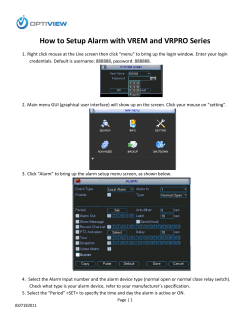


© Copyright 2026