
RedFlash, AirFlash, AutoFlash Manual Assembly and Operating Instructions Flash Model Overview Electrical Requirements
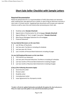
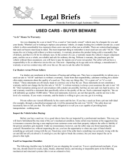
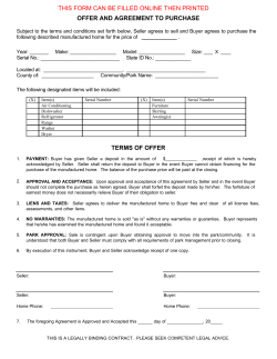
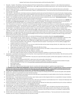
Year of Manufacture: 2014 Doc # 01-03-029B Original Instructions RedFlash, AirFlash, AutoFlash Manual Assembly and Operating Instructions This manual contains the following documents. Flash Model Overview Electrical Requirements Stand Components Safety Information Assembly and Installation Operation and Controls AutoFlash Setup AutoFlash Operation 01-00-005 Warranty 01-00-006 Warranty Summary Sheet 01-00-015 Terms and Conditions Wiring Diagram Vastex International, Inc. 1032 N. Irving St. Allentown, Pa. 18109 USA Phone# 610 434-6004 Fax# 610 434-6607 Web Site www.vastex.com Authorized Representative in Europe: Certification Experts BV Nieuwstad 100 1381 CE Weesp, The Netherlands Tel : + 31 (0) 294 – 48 33 55 Fax : + 31 (0) 294 – 41 46 87 Vastex E-mail assistance Electrical Drawing #: ____________________ Rev: _______ VTX Serial #: ________________________ Date: ____/____/____ Purchasing & Product Info: [email protected] Electrical Support: [email protected] Tech Support, Mechanical Setup, and Operation: [email protected] Screen Printing Issues & Support: [email protected] (Please log your machine's serial number and date of purchase for future reference.) 1 Flash Model Overview Vastex RedFlash R-18-240 (shown on SHHD Stand) R-18-240-HO R-1824-240 (shown on Standard Stand) Vastex AirFlash RA-18-240 (shown on Standard Stand) RA-1824-240 (shown on SHHD Stand) Vastex AutoFlash AF-120 AF-240 (shown on Standard Stand) 2 AF-240 (shown on SHHD Stand) Electrical components and requirements 18” x 18” RedFlash R-18-240: 240 Volts, 11 Amps, 50/60 Hz, 2600 Watts. Supplied with a required NEMA 6-15P Plug. R-18-240-HO: 240 Volts, 16.5 Amps, 50/60 Hz, 3500 Watts Supplied with a required NEMA 6-20P Plug. Requires a dedicated outlet on a properly rated 20 amp circuit. 18” x 24” RedFlash R-1824-240: 240 Volts, 16.5 Amps, 50/60 Hz, 3500 Watts Supplied with a required NEMA 6-20P Plug. Requires a dedicated outlet on a properly rated 20 amp circuit. 18” x 18” AirFlash RA-18-240: 240 volts, 17.5 Amps, 50/60 Hz 3500 Watts Supplied with a required NEMA 6-20P Plug. Requires a dedicated outlet on a properly rated 20 amp circuit. 18” x 24” AirFlash RA-1824: 240 Volts, 22 Amps, 50/60 Hz, 4300 Watts Supplied with a required NEMA 6-30P Plug. Requires a dedicated outlet on a properly rated 30 amp circuit. AutoFlash Unit AF-120: 120 Volts, 1 Amp Supplied with required NEMA 5-15P plug. AF-240: 240 Volts, .5 Amps Supplied with required NEMA 6-15P plug. Do not modify the power cord or plug. If unsure of your power source, consult a qualified electrician. 3 Stand Components SH-STAND-WS Doc #: 01-03-032A Contents of Standard Stand box for Manual Flash Spot Heater Saddle (4) Legs Locking Collar/Knob Spot Heater Column Hardware Package (4) Locking Casters Wrench 1-1/4” SHHD-STAND-M Contents of Heavy Duty Stand box for Manual Flash Center Brace Stand Leg (Left) Spot Heater Saddle Hardware Package (4) End Caps (4) Locking Casters (2) Tube Clamp Spot Heater Column Mounting Hardware Stand Leg (Right) SHHD-STAND Locking Collar/Knob Contents of Heavy Duty Stand box for AutoFlash Stand Leg (Left) Center Brace Hardware Package (4) End Caps (4) Locking Casters (2) Tube Clamp Mounting Hardware Stand Leg (Right) SH-LEG-AF Contents of Standard Stand box for AutoFlash (4) Legs Hardware Package (4) Locking Casters Wrench 1-1/4” 4 Instructions for placing the equipment into service This manual contains assembly and operating instructions for three product lines: RedFlash, AirFlash, and AutoFlash. Refer to page 3 of this manual to determine the electrical requirements for your product. Ensure that your electrical supply matches the requirements of your unit; if it does not, consult a licensed electrician for assistance. 1.) Begin by assembling your unit’s stand. See page 2 of this manual if you are unsure which stand type you have (standard or SHHD heavy-duty). Stand components are shown on page 4. Follow the standard stand assembly directions on page 6, or the heavy-duty stand assembly instructions on page 7, as appropriate to your stand. 2.) Assemble your head unit onto your saddle as shown on page 7. 3.) If you own an AutoFlash model, follow the additional AutoFlash setup instructions on pages 9 and 10 before operating your machine. Instructions for use of this equipment For RedFlash and AirFlash models: follow the instructions on page 8 of this manual. For AutoFlash models: follow the instructions on page 11 of this manual. Stability during use, transportation, assembly, testing, and foreseeable breakdowns This equipment is designed and expected to be stable during all foreseeable conditions, provided that the cautions (page 6) and instructions in this manual are followed. Do not place any objects on machine heads. If it is necessary to remove the column from the stand, lay the saddle/head assembly flat on the ground — do not try to balance it upright. Safe transport, handling, and storage This equipment is designed to be as safe as possible under all foreseeable conditions of transport, handling, and storage. Be certain to switch the equipment off, unplug it, and let it cool before handling any parts that become hot during operation, and before storing. When handling your machinery, be aware of the following weights and dimensions: R‐1824‐240 (Head Only) 43 lbs (19.5 kg) 26" x 35" x 8" (66 x 90 x 20 cm) R‐18‐240 (Head Only) 35 lbs (16 kg) 26" x 29" x 7" (66 x 74 x 18 cm) RA‐18‐240 (Head Only) 64 lbs (29 kg) 29” x 26” x 15” (74 x 66 x 38 cm) RA‐1824‐240 (Head Only) 74 lbs (35.5 kg) 35” x 29” x 15” (89 x 74 x 38 cm) AF‐120/AF‐240 AutoFlash kit 51 lbs (25 kg) 31" x 22" x 14" (79 x 56 x 36 cm) SH‐STAND‐WS Standard Stand for Manual Flash 22 lbs (10 kg) 37" x 7" x 3" (94 x 18 x 8 cm) SHHD‐STAND‐M Heavy Duty Stand for Manual Flash 42 lbs (19kg) 30” x 14” x 7” (76 x 35.5 x 18 cm) SH‐LEGS‐AF Standard Stand for AutoFlash 15 lbs (7 kg) 37" x 7" x 3" (94 x 18 x 8 cm) SHHD‐STAND Heavy Duty Stand for AutoFlash 39 lbs (18 kg) 30” x 15” x 11” (76 x 38 x 28 cm) 5 Safety Information The operator should read and understand the instruction manual before operating this equipment. Store this manual and safety information near the equipment for easy access to operators. VASTEX flash units are intended for the curing of non-flammable inks on screen printed materials. Do not use for any other purpose unless authorized by Vastex International, Inc. Use of this equipment for any other purpose can be dangerous and may cause damage to this equipment, voiding the warranty. It is recommended that the area around this equipment be designated as a work area and only authorized employees are allowed in this area. Children and pets must be kept clear from the work area. Do Not place any objects on top of the heater or control box; surfaces are hot. Never leave equipment unattended. DO NOT operate any flash units with any cover or guard removed. Do Not operate if the power cord or heater face is damaged. Operator must be familiar with the controls of the flash unit before operating. Before starting production, check that all covers and guards are in place, no material has been left on the flash unit, and the work area is clear of obstructions. Make certain when turning on the heater that it is not positioned over any flammable material, including the printer pallet. If heater is allowed to dwell over pallet for extended periods of time it will damage the pallet surface. Always turn off power at the main disconnect at the end of production. Do Not remove any cover or guard until power at the main disconnect is switched off and locked out. No unauthorized persons are to be allowed inside the control boxes. Turn off and lock out power at the main disconnect before cleaning and maintenance. Only qualified technicians should be allowed to make repairs on VASTEX Flash Units. Noise and vibration: These units do not produce noise exceeding 70 dB(A). Warning Heat Control and/or power switch should be switched off before plugging and/or unplugging the power cord. RedFlash Units are equipped with a cooling fan. Fan operates when heat control is turned on. Do Not use flash unit if cooling fan is not operating. Replace fan immediately if NOT operational. See the controls section for cooling fan replacement and ordering information. Stand Assembly Instructions Standard Stand Assembly Flash Tube Tools Required: 7/16”, 9/16” & Adjustable Wrench 1-1/4” Wrench (supplied) Cross Bolt 1/4” x 2-1/4” lg. & lock nut 1) Position the legs as shown below and bolt together with 1/4” bolts and serrated lock nuts. Do not fully tighten at this time. Use the 1-1/4” wrench, supplied and the 9/16” wrench to attach casters to each leg with 3/8” serrated lock nuts. 2) Slide the square tube into the stand until it is flush with the bottom. Install the cross bolt and nut. Then tighten all bolts. 6 Heavy Duty Stand Assembly Tools Required: Center Channel 3/8”, 9/16”, 3/4” Wrench 3/8” Socket and Ratchet Channel Lock Pliers (6) screws on top (2) screws on bottom 1) The Main Assembly must be screwed together using (16) sheet metal screws. Use a 3/8” socket and ratchet to install. There are (8) screws that need to be installed on each Stand Leg, (6) on the top, and (2) on the bottom. Assemble the stand as shown to the right and tighten all screws well. Stand Leg Main Assembly Sheet Metal Screws End Cap 1/2” Nut 2) Install a wheel in each End Cap with a 1/2” serrated lock nut; 3/4” wrench is required. Use (8) sheet metal screw to attach the (4) End Caps onto the stand legs. Use a 3/8” socket and ratchet to install. Caster End Cap installed Flash Tube 3) Attach the Tube Clamps onto the Center Channel with 3/8” bolts, lock washers, and nuts. Do not tighten the bolts. Install the four upper bolts and serrated lock nuts. Do not tighten these bolts. Insert the flash tube into the tube clamps. It must be bottomed out against the center channel. Tighten all the upper bolts first, followed by all the lower bolts. (4) 3/8” Bolts, Serrated Locking Nuts Tube Clamps Center Channel (4) 3/8” Bolts, Flat Washers & Lock Washers Assembly Head installation on saddle Tools Required: 1/4”, 9/16” Wrench Care must be taken to avoid damage to the heater face. Do Not operate if the heater face or power cord is damaged. 2) Slide the locking collar onto the saddle tube and insert saddle into the column. 1) Uncoil the power cord and loosen the two mounting bolts about 1/8”. Mounting bolts Saddle 3) Insert the mounting bolts of the flash head into the slots of the saddle. When fully inserted into the saddle the head will be supported. Tighten the mounting bolts. 4) Turn the knob to level the head over the pallet. Tighten the knob after leveling. S Not n how Manual Flash Head Mount 5) Install the handles on each side of the flash unit using the four self tapping screws. Do not over tighten. Handles not recommended on an AutoFlash unit. 7 Locking Collar AutoFlash Head Mount Operation & Controls Read the safety information before operating the flash unit. Heater Height Adjustment Heating Operation The REDFLASH will effectively dry all types of plastisols and thermoset inks. Set the control to position 5 and a distance of 2-4" from the face of the heater to the surface of the garment. The normal dwell time under the heater is the time you spend printing another garment. Nevertheless, 6-10 seconds is the time needed to effectively “skin-over” the ink deposit. Adjustments to the temperature control and distance may have to be made for the specific application. You should not try to final Locking collar cure with a spot heater due to the fact that matching the precise time in heat of a conveyor will be difficult and can cause damage to your pallet. (Caution should be taken when operating the flash unit. The heater surface is very hot. Never leave the flash unit on and left unattended.) To raise and lower the flash head, grasp the saddle post firmly, loosen the locking collar knob, adjust the height and retighten the knob. Saddle post Controls -Heat Controller The control has positions LO-2-3-4-5-6 and HI. The controller turns the power to the heater on and off to vary the temperature. The higher the number on the controller the longer the on cycle and shorter the off cycle is. The “HI” position keeps the power on constantly. The light indicates controller is on. RedFlash control panel -Heat On This RED light is wired to the controller. It will illuminate when the control is turned on, even if the controller has failed. -Cooling Fan RedFlash Units are equipped with a cooling fan. Fan operates when heat control is turned on. Do Not use flash unit if cooling fan is not operating. Replace fan immediately if NOT operational. Order p/n 04-02052 replacement fan from Vastex International Inc. -RedFlash Shut Down Procedure: Turn heat control to “LO” for 10 minutes. Then turn off heat control. AirFlash control panel Cooling Fan Flash Cover Cooling Fan Replacement: 1) Unplug or switch off power at the main disconnect. 2) Remove plug from cooling fan. 3) Remove Flash Cover mounting screws. 4) Remove failed fan, install new fan, airflow direction is down. 5) Transfer ground wire, warning label plate and guard onto new fan. 6) Reverse step 1-3 to complete reassemble. Air Controls (AirFlash Only) RedFlash W/ Cooling Fan Filter Retainer The Airflash blower runs when the main power switch is on. The AirFlash air controls are operated using a single knob. Loosen and slide the air flow adjust knob to control the air flow through the heater. Adjust from “full on” to “off” (bypass) as needed. The air is also used to cool the flash unit; replace blower when necessary. Air Intake Filter Air Flow Adjust Knob 8 Clean the air intake filter regularly. Slide the filter retainer up to access the filter. AutoFlash Setup Cooling Fan Detent Flash Head Driver Loosen Locking Lever to Adjust Height and Set Home Position Flash Head Dwell Timer Main Power Switch *Max Height: 45" *Min Height: 35" AutoFlash Unit *When using the Standard Stand with your Autoflash Foot Pedal With casters Max Height: 42" Min Height: 32" With Levelers Max Height: 40" Heavy Duty Stand Min Height : 30" Installing AutoFlash Unit on to the HD Stand Installing AutoFlash Unit on to the Standard Stand A 9/16"wrench is required for this step. A 7/16 “ wrench is required for this step. Have the bolts in the stand loose to start. Slide the AutoFlash tube into the stand until it is flush with the bottom then tighten all bolts. Attach the Tube Clamps onto the Center Channel with 3/8” bolts, lock washers, and nuts. Do not tighten the bolts. Install the four upper bolts and serrated lock nuts. Do not tighten these bolts. Insert the flash tube into the tube clamps. It must be bottomed out against the center channel. Tighten all the upper bolts first, followed by all the lower bolts. AutoFlash Tube 1/4” Bolts & Serrated Lock Nuts AutoFlash Tube Tube Clamps (4) 3/8” Bolts, Serrated Locking Nuts Center Channel With the 1/4” bolts loose, slide the AutoFlash tube into the stand until it is flush with the bottom. Then tighten all bolts. (4) 3/8” Bolts, Flat Washers & Lock Washers 9 Detent Flash Head Driver AutoFlash units manufactured after Jan 1, 2013 are equipped with the Detent Flash Head Driver mechanism. The Detent Flash Head Driver functions as an over ride mechanism. If there is an obstruction in the path of the Flash Head, the AutoFlash will complete its cycle and return to home position. Clear the obstruction and rotate the Flash Head back to home position. If the AutoFlash unit malfunctions, the Flash Head can be manually rotated until repairs can be made. See below for setting Flash Head home / extend position and height adjustment. Detent Plate Upper w/Locking Lever Detent Drive Plate AutoFlash Setup Setting Home/Extended Positions for the Flash Head Standard rotation is shown, see next page for reversing rotating direction of the AutoFlash. Loosen the locking lever and rotate the flash head until it is aligned as shown below and tighten the locking lever. Turn on the main power switch and let the machine cycle back to home position. The proper orientation of the flash unit to the control box is now set. To adjust the flash head height, support the flash head and loosen the locking lever. Adjust to the desired height and tighten the locking lever. Recheck that extend position has been maintained. Position the Flash Unit in a clear area of the shop. Plug in the AutoFlash unit. Set the dwell timer to greater than 15 seconds. Press the foot pedal to activate the AutoFlash unit. Once the AutoFlash rotates to the extended position, switch off the main power switch. This will stop the machine in the extended position. While in the extended position, firmly grasp the flash head. Do Not position the flash head over the control box when in the home position. Excessive heat can damage the electrical components. Home Position (Standard Rotation) Flash Head Extended Position (Standard Rotation) HD Stand AutoFlash Unit Control Face HD Stand AutoFlash shown in Home & Extended position Standard Rotation (top view) 10 AutoFlash Operation Operating the AutoFlash 1) Check that the main power switch is in the off position. 2) Plug in the AutoFlash. 3) Set the timer to the desired dwell time over the pallet. 4) To adjust the Flash Head height, firmly grasp the Flash Head, loosen the locking lever and raise or lower as needed. Retighten locking lever. Maintain the proper orientation of the flash unit to the control box when adjusting the height. 5) Move the Flash Unit into position and lock casters. 6) Press the foot pedal once to activate the AutoFlash. It will rotate the Flash Head over the pallet, dwell for the preset time and return to home position. 7) Always unplug the AutoFlash and Flash Head at shifts end. Note: If the AutoFlash unit malfunctions, the Flash Head can be manually rotated until repairs can be made. Reversing an AutoFlash Rotation Reversing the Rotation of an AutoFlash Replace the side cover. It will now be necessary to reset home position. See section for setting home and extend position.If the AutoFlash is in a SHHD Stand, loosen the tube clamp bolts lift the AutoFlash unit out of the stand rotate 180 deg., retighten bolts. Reset home and extend position. Disconnect your unit from its power source. Remove the left side cover to access the limit switches. Two limit switches control the rotation of the flash head. The wires are all labeled. Reversing the order of the wires will result in reversing the rotation of the flash head, see pictures below. Once this is done the HOME Position is now AWAY and AWAY is HOME. Extend Limit Switch Extend Limit Switch #3 Wire #4 Wire #5 Wire #6 Wire Open Position #7 Wire #7 Wire Open Position #6 Wire #5 Wire #4 Wire #3 Wire Home Limit Switch Home Limit Switch Standard Rotation Reversing Rotation 11 Maintenance and Troubleshooting Safe maintenance and troubleshooting: Before beginning any maintenance or troubleshooting on your equipment, unplug your machine from its electrical outlet. The heat control and/or power switch should be switched off before plugging and/or unplugging the power cord. Allow time for the equipment to cool before attempting any service on the heater Do not remove any panels with the equipment powered on; any such service must be performed by qualified personnel only. If your machine appears to be operating abnormally and the troubleshooting charts below do not resolve your problem, shut your unit off, unplug it, and contact Vastex for further assistance. In the event of a malfunction or breakdown: Shut off power to the equipment and unplug from electrical outlet. Then, following the troubleshooting charts below. If this does not resolve your issue, please contact Vastex for support. Troubleshooting Chart—All Models: Symptom Possible Cause Solution No Heat Machine unplugged? Faulty temperature controller Faulty heater Plug into appropriate outlet Contact Vastex for assistance Contact Vastex for assistance Fan/blower not running Faulty fan/blower Replace fan/blower Heat on, cannot be controlled Faulty temperature controller Contact Vastex for assistance Troubleshooting Chart—Additional Considerations for AutoFlash Units: Symptom Possible Cause Solution Unit stops in wrong location Home and extended positions incorrectly set Follow instructions on page 10 to set User wishes to reverse rotation direction of AutoFlash N/A Follow instructions on page 10 to reverse direction Maintenance: Your equipment is designed to provide a long service life with little maintenance required. Before using your machine at the beginning of each work shift, check that its fan is working. Do not operate if the fan/blower has failed. On AirFlash models, clean the air filter regularly (see page 8). On all models, periodically check the heater face and power cord to ensure that neither has become damaged. Periodically verify correct functioning of all controls. 12 Vastex Warranty Doc#01-00-005B Revised 04/10/12 (1.) Vastex, hereinafter referred to as “seller” warrants only to its original “purchaser”, who holds a copy of the original invoice and is the original end user of the equipment in question, its new equipment against defects in materials or workmanship on a pro-rated basis. Warranty period begins from date of shipment to the buyer and will only apply to customers paid in full. Warranty periods are as follows: one (1) year for E-1000, three (3) years for all other complete machines (including F-Flash), fifteen (15) years for infrared heaters (excluding FFlash) installed by Vastex in a new dryer, three (3) years for replacement infrared heaters, and one (1) year for replacement parts. Rubber blankets, light bulbs and glass on exposure units are particularly subject to wear while in use. Wear is not covered by this warranty but as stated above only manufacturers defects are covered. All sales made through Vastex dealers must be certified by that dealer before a warranty replacement is issued. (2.) This warranty is expressly contingent upon the buyer delivering to seller, at the address below, with all transportation charges prepaid, the part or parts claimed to be defective within the above mentioned warranty periods stated in paragraph one. The defective part or parts will be repaired or replaced at the discretion of Vastex International, Inc. If the equipment in question is less than one (1) year old, it will be shipped to the customer at no charge, with an RGA issued by Vastex for the defective part. The defective part must be shipped back to Vastex freight prepaid within 30 days or the account will be billed. If the equipment is more than a year old, the part will be shipped after we receive the defective part. If it’s necessary to expedite the movement of parts and to minimize down time to the buyer, the replacement part shall be supplied on a C.O.D. basis. If testing and analysis of said part by the seller or its supplier discloses that said part is defective, the cost of said part will be refunded to the buyer on a prorated basis. (3.) Except as otherwise provided herein, the equipment is being sold “as-is”. Final determination of the suitability of the equipment for the use contemplated by the buyer, is the sole responsibility of buyer, and seller shall have no responsibility in connection with the suitability. (4.) All warranties implied by law, including the implied warranties of merchantability and fitness are hereby limited to workmanship and defective parts to a warranty period stated in paragraph one. The express warranty and remedies contained herein and such implied limited warranties are made solely to the sole warranties and remedies and are in lieu of all other warranties, guarantees, agreements, and other liabilities, whether express or implied, and all other remedies for breach of warranty or any other liability of seller, in no event shall seller be liable for consequential damages. No person, agent, distributor, or service representative is authorized to change, modify or extend the terms hereof in any manner whatsoever. These terms and conditions are an essential part of the transaction between the parties and constitute the entire agreement between them with respect to the same. Some states do not allow limitation on how long an implied warranty lasts of the exclusion or limitation of incidental, or consequential damages, so the above limitation may not apply to you. This warranty gives you specific legal rights, and you may also have other rights which vary from state to state. Infrared heaters are the only replacement parts covered for a period of (3) years from date of shipment and contingent to receipt of payment in full. Electrical components cannot be returned once installed unless proven defective. Please refer to doc. 01-00-015 for specific terms and conditions of sale and the limited warranty. Please refer to doc. 01-00-017 for V-2000HD printer warranty. Updates: V1000 to 3 year warranty 01/09/12, Heater warranty to 15 years 01/02/2012. --------------------------------------------------------------------------------------------------------------------------------------------------------------------------------------------------------------------TERMS AND CONDITIONS OF SALE AND LIMITED WARRANTY Doc.#01-00-015 1. Buyer’s order will constitute an offer in accordance with the terms hereof and such offer, upon acknowledgment of Seller, will constitute the agreement between Buyer and Seller. Buyer’s order after such acknowledgment by Seller will not be subject to cancellation, change or reduction in amount, or suspension by Buyer of deliveries, unless prior to such action Buyer has obtained Seller’s written consent. Notwithstanding anything to the contrary in Buyer’s Purchase Order or other communications, the parties agree to be bound by these Terms and Conditions. Acceptance of the product by the Buyer shall be deemed to constitute unconditional acceptance of these Terms and Conditions. 2. Any of these terms, conditions and provisions of Buyer’s order which are inconsistent with Seller’s acknowledgment and these Terms and Conditions of Sale shall not be binding on the Seller and shall be considered not applicable to any sale so made. No waiver, alteration or modification of any of the provisions on either side of the document shall be binding upon Seller unless agreed to in writing by Seller. (a) All prices are F.O.B. Seller’s Plant and method of delivery and routing shall be at Seller’s discretion, unless specifically otherwise stated herein. Notwithstanding any agreement to pay freight, delivery of products purchased hereunder to a common carrier or licensed trucker shall constitute delivery to Buyer and be determinative of the date and time of shipment and all risk of loss or damage in transit shall be borne by Buyer. If the Buyer fails to accept the goods from the common carrier or licensed trucker, the Seller shall be entitled to claim payment from the Buyer. Seller shall arrange for storage, the risk and the cost, including insurance costs, to be borne by the Buyer (and Buyer agrees to pay such amounts upon demand) except if the failure to accept delivery is due to any of the exceptions noted in Paragraph 4. (b) Terms of payment shall be as stated on invoice. It is understood that deliveries will be made in accordance with Seller’s regular production schedule. Every reasonable effort will be made to meet the Buyer’s required delivery dates but Seller will not be liable for damages or be deemed to be in default by reason of any failure to deliver or delay in delivery due to any preference, priority, allocation or allotment order issued by the Government, whether Federal, State or local, or causes beyond its control including but not limited to, Acts of God or a public enemy, acts of Government, fires, floods, epidemics, quarantine restrictions, strikes, lockouts, freight embargoes, severe weather, unavailability of materials or shipping space, delays of carriers or suppliers or delays of any subcontractors. Should delay in delivery be caused by any of the circumstances mentioned in this paragraph, such extension of the delivery period shall be granted as is reasonable under the circumstanced of the case. Should delay be caused by an event not specifically mentioned in this paragraph, damages will be limited to cancellation of the purchase order without penalty, and refund of any monies deposited or prepaid on the purchase order with no liability for any consequential or incidental damages. Seller reserves the right to increase the prices prior to Seller’s acceptance of order and/or after expiration of any price quoted by Seller. Unless otherwise stated in writing, Seller’s prices do not include sales, excise, value-added or other taxes. Consequently, in addition to the price specified herein, the amount of any present or future sales, use, excise, value-added or other tax applicable to the manufacture, sale, purchase or use of the products hereunder shall be paid by Buyer, or in lieu thereof, Buyer shall provide Seller with a valid tax exemption certificate acceptable to the taxing authorities. Seller reserves the right, at any time, to revoke any credit extended to Buyer because of Buyer’s failure to pay for any products when due or for any other reason deemed good and sufficient by Seller and in such event, all subsequent shipments shall be paid for prior to at delivery at Seller’s option. (a) SELLER’S LIABILITY SHALL BE LIMITED TO SELLER’S STATED SELLING PRICE PER UNIT OF ANY DEFECTIVE GOODS AND SHALL IN NO EVENT INCLUDE BUYER’S MANUFACTURING COSTS, LOST PROFITS, GOODWILL, OR ANY OTHER SPECIAL, INDIRECT, INCIDENTAL OR CONSEQUENTIAL DAMAGES, ARISING OUT OF THE AGREEMENT, THIS CONTRACT, THE SALE OF THE PRODUCTS TO THE BUYER OR THE USE OR THE PERFORMANCE OF THE PRODUCTS. Seller may at its discretion repair, replace or give the Buyer credit (pro-rated) for such defective products. (b) Notwithstanding anything herein to the contrary, Seller shall have no liability for alleged defects with the products which are not specified in written notice from the Buyer to the Seller within thirty-six (36) months from the date of shipment of machines. Seller shall pass to Buyer any warranty received by Seller from the manufacturer of Limited Life Components, which in most cases is 12 to 18 months. (c) Seller shall have no liability under this Limited Warranty unless Buyer has paid in full for the products. Further, this Limited Warranty is expressly contingent on Buyer’s delivery to Seller, all costs prepaid, the defective part(s) within thirty-six (36) months of shipment to Buyer, together with a written statement specifying the alleged defect(s). Any replacement part(s) shall be shipped to Buyer on a C.O.D. basis. (d) SELLER SPECIFICALLY EXCLUDES ALL WARRANTIES, EXPRESSED, IMPLIED OR OTHERWISE, EXCEPT AS STATED EXPLICITLY IN THESE TERMS AND CONDITIONS OF SALE. SELLER DISCLAIMS THE WARRANTY OF MERCHANTABILITY AND FITNESS FOR A PARTICULAR PURPOSE. The remedies herein reserved by Seller shall be cumulative and in addition to any other legal remedies. No waiver of a breach of any portion of this contract shall constitute a waiver of continuing or future breach of such provision or of any other provisions hereof. These Terms and Conditions constitute the entire agreement of the parties. No amendments, changes, revisions or discharges hereof in whole or in part shall have any force or effect unless set forth in writing and signed by the parties hereto. This contract shall not be assignable by Buyer voluntarily by operation of law or otherwise without Seller’s written consent. This contract shall be governed and shall be construed according to the domestic laws of the Commonwealth of Pennsylvania. Anything herein to the contrary notwithstanding, any action for alleged breach by Seller of the contract between the parties, including but not limited to any action for breach of the warranties herein set forth, shall be barred unless commenced by Buyer within one (1) year from the date such cause of action accrued. This agreement shall inure to the benefit of and be binding upon the parties hereto, their respective successors and permitted assigns. All notices required by this contract to be given by either party shall be sent in writing or by facsimile and shall be addressed to the last known address of such other party. Notices shall be deemed to have been received on the fifth business day following deposit in the mail. 3. 4. 5. 6. 7. 8. 9. 10. 11. 12. 13. 14. 13 VASTEX WARRANTY IMPLEMENTATION SHEET Please read this document in order to fully understand the warranty. Doc.# 01-00-006 Your new Vastex equipment is protected against *manufacturers’ defects by our warranty, completely explained in doc# 01-00-017 for the V2000-HD series manual printer and in doc# 01-00-005 for all other Vastex manufactured equipment. Please refer to these documents for the **warranty term and specific concerns about the warranty. The following are some important facts and requirements for the proper implementation of the warranty. 1.0 Everything is covered! 2.0 **Warranty Term is defined as: Ship date from VASTEX to the date the item in question is returned to VASTEX for inspection and repair. 3.0 *Manufacturers defects are defined as: Parts determined to be defective in workmanship which will lead up to a premature failure. The determination will be made only by the manufacturer of the item in question. 4.0 To take advantage of the warranty the following steps must be taken: 4.1 The equipment must be paid for in full. 4.2 The item in question must be shipped to VASTEX for evaluation with all shipping costs incurred by the buyer. 4.3 If the item is deemed as a manufacturer’s defect it will be repaired or replaced within 2 business days from the time received. The shipping cost back to the customer located in the continental United States will be paid by VASTEX if a warranty item. 4.4 If the item in question must be replaced immediately and is more than a year old, it will have to be purchased at list price and will be shipped COD. A pro-rated credit will be given promptly if the returned item is a valid manufacturer’s defect. 4.5 If the equipment was shipped less than a year before the date of the service call and a technician confirms the part needed for repair, the replacement will be shipped before the replacement is shipped back. An RGA will be issued and must accompany the old part to VASTEX within 30 days or the account will be billed. 5.0 Important facts about the condition of shipped equipment: 5.1 Dryers are partially assembled with the belts tracked and the machine run at full temperature for a min. of 1 ½ hours. 5.2 Printers are partially assembled, inspected, and adjusted for all heads down prior to partial disassembly and packing. 5.3 Exposing units are fully assembled and tested with the maximum screen size for vacuum integrity, timer operation and light output. 6.0 This document is in addition to the standard warranty and only helps the customer understand how to take advantage of the warranty. In no way does this document override the standard warranty or the terms and conditions of sale and the limited warranty doc# 01-00-015. Please see doc# 01-00-015 for specific terms and conditions of sale and the limited warranty 14


© Copyright 2026