
LEON VxWorks 6.7 Generic BSP Manual VxWorks-6.7 Generic BSP Manual 1 .
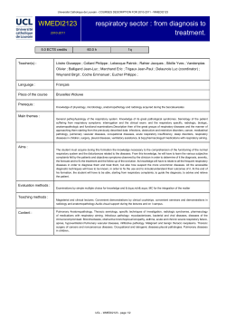
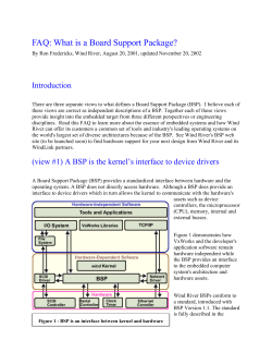
.
VxWorks-6.7 Generic BSP Manual
1
LEON VxWorks 6.7 Generic BSP Manual
VxWorks-6.7 LEON specific BSP manual
VXWORKS-6.7-BSPS
Version 1.0.8
May 2014
Kungsgatan 12
411 19 Gothenburg
Sweden
tel +46 31 7758650
fax +46 31 421407
www.aeroflex.com/gaisler
VxWorks-6.7 Generic BSP Manual
VxWorks-6.7 Generic BSP Manual
Copyright © 2009 Aeroflex Gaisler AB
2
VxWorks-6.7 Generic BSP Manual
iii
Table of Contents
1. Introduction ...................................................................................................................... 1
1.1. Hardware ............................................................................................................... 1
1.2. Source code ........................................................................................................... 1
1.3. LEON2/3 peripherals ............................................................................................... 2
1.4. MMU support ........................................................................................................ 3
1.5. FLASH support ...................................................................................................... 3
2. Examples ......................................................................................................................... 4
2.1. MIL-1553B ............................................................................................................ 4
2.1.1. Usage ......................................................................................................... 4
2.2. Spacewire .............................................................................................................. 4
2.2.1. Usage ......................................................................................................... 4
2.3. SPI ....................................................................................................................... 5
2.3.1. Usage ......................................................................................................... 5
2.4. OC-CAN ............................................................................................................... 5
3. Memory Configuration ....................................................................................................... 6
3.1. Stack .................................................................................................................... 6
4. Memory Management Unit ................................................................................................. 7
4.1. Initialization ........................................................................................................... 7
4.2. Adding a virtual to physical map ............................................................................... 7
5. Booting from persistent memory .......................................................................................... 8
5.1. LEON Boot loader .................................................................................................. 8
5.1.1. BOOTCFG_FREQ_KHZ ............................................................................... 8
5.1.2. BOOTCFG_UART_BAUDRATE ................................................................... 8
5.1.3. BOOTCFG_UART_FLOWCTRL .................................................................... 9
5.1.4. BOOTCFG_WASH_MEM ............................................................................. 9
5.1.5. BOOTCFG_DSU3_ADDRESS ....................................................................... 9
5.1.6. Memory controller configuration options .......................................................... 9
5.1.7. Clock gating unit .......................................................................................... 9
5.2. Booting VxWorks kernel from persistent memory ......................................................... 9
5.2.1. Selecting build rule ....................................................................................... 9
5.3. Bootrom .............................................................................................................. 10
5.3.1. Configuring the boot loader .......................................................................... 10
5.3.2. Creating a bootrom project ........................................................................... 11
5.3.3. Building the bootrom .................................................................................. 11
5.3.4. Installing and running the bootrom ................................................................. 11
5.3.5. Troubleshooting .......................................................................................... 12
6. Interface ......................................................................................................................... 13
6.1. Function interface ................................................................................................. 13
6.1.1. sysOut* and sysIn* ..................................................................................... 13
6.2. VxWorks exception handling .................................................................................. 13
7. Compilers ....................................................................................................................... 14
8. Drivers .......................................................................................................................... 15
9. Support .......................................................................................................................... 16
10. Disclaimer .................................................................................................................... 17
VxWorks-6.7 Generic BSP Manual
1
1. Introduction
This document aims to provide documentation for the SPARC/LEON specific Board Support Packages
(BSPs). The Aeroflex Gaisler distribution contains both board specific BSPs as well as a generic BSP for
custom LEON systems. All BSPs can be found in the vxworks-6.7/target/config directory.
The BSPs implement the necessary functions needed by the SPARC port to function. They handle memory
set up, trap table, MMU, driver selection and so on.
The generic BSP does not target a single board. Instead it tries to be general and support as many boards as
possible. This is possible due to the Plug&Play support on the CPU bus. However, some parameters needs
to be setup. Especially important are the memory parameters that must be set up in order to start a VxWorks
kernel. When booting from FLASH/PROM the boot loader parameters must also be set up.
1.1. Hardware
The supported hardware is summarized in the list below. For documentation about a specific core's driver
please see the LEON VxWorks 6.7 Driver Manual.
•
•
•
•
•
•
•
•
•
•
•
•
•
•
•
•
•
•
•
•
•
•
•
•
•
•
LEON2 and LEON3
MMU and non-MMU systems
FPU, non-FPU, hardware MUL/DIV and software MUL/DIV support
Interrupt controller
UART console/terminal driver
Timer unit
General Purpose I/O (GRGPIO)
10/100 Ethernet networking (GRETH, LAN91C111)
10/100/1000 Ethernet networking (GRETH)
SpaceWire (GRSPW)
DMA CAN 2.0 (GRCAN)
non-DMA CAN 2.0 (OCCAN)
1553: BC, RT and BM support (GR1553B) and basic support for B1553BRM BC, RT and BM
Host USB 1.1 and 2.0 (GRUSBHC)
I2C Master (I2CMST)
GRTM Telemetry transmitter
GRTC Telecommand receiver
ADC/DAC controller (GRADCDAC)
PW2APB non-DMA PacketWire Receiver
APB2PW non-DMA PacketWire Transmitter
PCI support (GRPCI, GRPCI2, PCIF)
PCI support (AT697 PCI for non-MMU BSP)
GR-RASTA-IO PCI Peripheral
GR-701 PCI Target
GR-RASTA-ADCDAC PCI Peripheral
GR-RASTA-TMTC PCI Peripheral
1.2. Source code
The generic LEON BSP is named gr_sparcleon and has to be adapted to the specific board. For new
development this is the recommended BSP to use if no board specific BSP is available. To disable MMU
support you can disable the component INCLUDE_MMU_BASIC. The BSPs starting with wrleon* come
in both MMU and non-MMU variants and does not support changing this in the kernel configuration. For
this reason they are not recommended for new development.
For GR712, UT699, UT700 LEAP and GR-CPCI-LEON4-N2X there are preconfigured BSPs based on the
gr_sparcleon BSP:
VxWorks-6.7 Generic BSP Manual
•
•
•
•
2
GR712 BSP vxworks-6.7/target/config/gr_sparcleon_gr712
UT699 BSP vxworks-6.7/target/config/gr_sparcleon_ut699
UT700 LEAP BSP vxworks-6.7/target/config/gr_ut700leap
GR-CPCI-LEON4-N2X BSP vxworks-6.7/target/config/gr_cpci_leon4_n2x
An overview of the sources in the generic BSP is given by the table below.
Table 1.1. LEON BSP specific sources
Source
Description
sysLib.c
The BSP system library implementation. This is the heart of the BSP. The code
handles reboot, system initialization in two stages, MMU setup and other needed
functions.
sysALib.s
Low level setup, such as stack, trap table. Calls usrInit().
config.h
Default BSP configuration. This file contains the default project configuration
when a project is created based upon the BSP. The settings can then be
overridden from the Kernel Configuration GUI. This file is normally customized
for a particular board.
configNet.h
Networking configuration, number of network interfaces, Ethernet MAC
number IRQ number of SMC91C111 etc.
romInit.s
Boot loader implementation, used to boot the bootrom (Small VxWorks kernel
with network boot capabilities) or standard kernel image. This contains the first
instructions executed when starting from FLASH/PROM. It initializes hardware
registers such as the memory controller, CPU, FPU, wash memory etc. The
settings are controlled by the configuration in bootcfg_def.h, config.h or project
configuration (FOLDER_BOOTCFG in Hardware/BSP configuration variants/
LEON ROM Boot setup).
bootcfg_def.h
Default boot loader configuration (used by romInit.s). It is included from
config.h and the settings can be overridden from the project configurations, or
a custom bootcfg_XYZ.h can be included instead of bootcfg_def.h.
bootloader.h
Used by the boot loader (romInit.s) to calculate some values such as timer
SCALER from system frequency.
Makefile
Makefile when compiling BSP (often bootrom). One must configure which
toolchain to use and the memory parameters to match config.h when creating
a bootrom.
hwconf.c
VxBus Driver/Device configuration controlled from project settings. For
LEON2 systems this also configures the hardware present apart from the basic
peripherals (TIMER, UART, IRQ).
*.cdf
BSP configuration files for WindRiver command line tools and Workbench
kernel configuration GUI.
sysI2C.c
GRLIB I2CMST driver implementation.
eepromI2CSlave.c
A simple I2C EEPROM driver. The EEPROM can be read and written, it does
not support all types I2C of EEPROMs but may serve as a start point for a custom
implementation.
usbPciStub.c
USB 1.1/2.0 driver implementation.
sysSerial.c
Serial UART/Console routines, called from sysLib.c
1.3. LEON2/3 peripherals
The LEON2 on-chip peripherals are assumed to reside in the default address as defined in the LEON2 VHDL
model. Also the interrupt assignment of UART and Timer are assumed to retain their default values. For
LEON3 systems, the address and interrupt is read from the on-chip Plug&Play information, and is assigned
during run-time.
VxWorks-6.7 Generic BSP Manual
3
1.4. MMU support
The generic BSP support the Memory Management Unit (MMU) which offers memory protection between
processes and kernel. Full protection can be achieved by not allowing processes to write each others private
memory and of course not to the kernel area. If such a violation occurs the kernel halts the faulting process
and the developer can find out what process and what instruction went wrong.
1.5. FLASH support
The UT699 and GR-CPCI-LEON4-N2X BSPs have support for reading and writing to the board provided
FLASH memory. The FLASH can, for example, be used to store a file system and/or to store NVRAM data
used by the boot loader.
By default a region of the FLASH memory is reserved for the boot image. The size of this region can be
modified by changing the value of the FLASH_RESERVE_FOR_BOOTIMAGE define in config.h. For
more information about using the FLASH for storing a file system, see Chapter 13 in the VxWorks Kernel
Programmer's Guide.
The FLASH can also be used to support NVRAM. By default the last block of the FLASH is reserved for
this. NVRAM can be enabled by defining SAVE_NVRAM_REGION and moved by changing the value of
NVRAM_START_ADDR. Both defines can be found in config.h. SAVE_NVRAM_REGION can also
be set in the kernel configuration under hardware/BSP configuration variants/Save NVRAM region on flash.
VxWorks-6.7 Generic BSP Manual
4
2. Examples
This chapter gives an overview of the example code provided with LEON VxWorks. For information on
how to create a project, see the provided Getting Started with LEON VxWorks guide. The example code can
be found in the installation directory. The examples are not BSP specific and might not be applicable to all
hardware, or might require modification. They are mainly intended to demonstrate usage of different drivers.
2.1. MIL-1553B
This example demonstrates the usage of the GR1553B driver. It consist of two parts, one for creating a bus
controller (BC) with a bus monitor (BM), and one for creating a remote terminal (RT) with a BM. Running
the application requires two devices connected together by MIL-1553B. One of the devices needs to run the
BC code and the other one the RT code.
2.1.1. Usage
Create two new image projects. Copy the files pnp1553.h, config_bm.h and gr1553bcbm.c to one
of the projects and add the following lines to usrAppInit in usrAppInit.c.
int gr1553bcbm_test(void);
gr1553bcbm_test();
Include the DRV_GRLIB_GR1553BC and DRV_GRLIB_GR1553BM components in the kernel
configuration. This project will take the role of the bus controller.
Copy the files pnp1553.h, config_bm.h and gr1553rtbm.c to the other project and add the
following lines to usrAppInit in usrAppInit.c.
int gr1553rtbm_test(void);
gr1553rtbm_test();
Include the DRV_GRLIB_GR1553RT and DRV_GRLIB_GR1553BM components in the kernel
configuration. This project will take the role of the remote terminal.
Executing the two images on two different devices connected by MIL-1553B will show the messages being
exchanged between the devices.
2.2. Spacewire
This example takes commands from STDIN and generates SpaceWire packets with the path or logical
address the user specififes. The application consists of three threads:
• TA01. Input task, the user commands from STDIN are interpreted into packet scheduling, time-code
generation or status printing.
• TA02. Link monitor task. Prints out whenever a SpaceWire link switch from run-state to any other state
or vice versa.
• TA03. SpaceWire DMA task. Handles reception and transmission of SpaceWire packets on all SpaceWire
devices.
Tick-out IRQs are catched by the time-code ISR, and printed on STDOUT.
2.2.1. Usage
Create a new project and copy the files grspw_pkt_lib.c, grspw_pkt_lib.h and grspw-test.c
to the project. Include the DRV_GRLIB_GRSPWPKT component in the kernel configuration. Add the
following lines to usrAppInit in usrAppInit.c.
void spacewire_test(void);
spacewire_test();
VxWorks-6.7 Generic BSP Manual
5
The example allows commands to be entered to send packets along arbitrary path. Use the h command to
display a list of available commands.
2.3. SPI
This example shows how to use the GRLIB SPI controller driver for single and periodic read/write transfers.
The single transfer example demonstrates communication with a AD7814 temperature sensor and the
periodic transfer example demonstrates communication with a AD7891 multi-channel AD converter.
2.3.1. Usage
Make sure that your board has the necessary hardware connected to the SPI controller. Create a new project
and copy either the file SPI-Single-AD7891.c or the file SPI-Periodic-AD7814.c to the project.
Include the DRV_GRLIB_SPICTRL component in the kernel configuration. Add the following lines to
usrAppInit in usrAppInit.c.
/* For single transfers */
void printTemperature(void);
printTemperature();
/* For periodic transfers */
void printChannels(void);
printChannels();
The single transfer example will read and display a temperature reading with a small task delay. The periodic
transfer example will repeatedly read the value of each channel from the AD converter and display the value
with a small task delay.
2.4. OC-CAN
This example shows how to use the GRLIB OC-CAN driver to communicate with devices on a CAN bus.
The example can be configured to act as a transmitter or receiver, or as both transmitter and receiver in
loopback.
2.1. Usage
Connect two devices using CAN, or use one device in loopback mode. Create a new project and copy the
files in the occan directory to the project. Include the DRV_GRLIB_OCCAN component in the kernel
configuration. Add the following lines to usrAppInit in usrAppInit.c.
#include "occan_test.h"
/* For testing loopback mode */
occan_test_loopback();
/* To act as receiver */
occan_test_receiver();
/* To act as transmitter */
occan_test_transmitter();
The example will send and/or receive messages and display the message count.
VxWorks-6.7 Generic BSP Manual
6
3. Memory Configuration
The memory configuration is not auto detected in VxWorks. It is instead up to the user to configure the
project with a valid memory configuration. The most important memory options are listed in the table below.
Table 3.1. BSP Memory parameters
Parameter
Description
LOCAL_MEM_LOCAL_ADRS
Start address of main memory.
Usually 0x40000000.
LOCAL_MEM_SIZE
Size of VxWorks available memory. Usually the memory size minus
the size of the reserved memory.
For example 0x3ff000 on a system with 4Mb RAM.
RAM_LOW_ADRS
Low RAM address. This is where the VxWorks image will be
placed before jumping into sysALib.s. The trap table is installed on
RAM_LOW_ADRS-0x3000.
Usually the low address is start of main memory + 0x3000,
0x40003000.
RAM_HIGH_ADRS
High RAM address. When the bootrom is used, the boot loader
places the small VxWorks kernel (the bootrom) at high RAM. The
RAM_LOW_ADRS..RAM_HIGH_ADRS is used by the bootrom
kernel to store the VxWorks kernel fetched from the network before
booting.
Usually set to half main memory + 0x3000, for example 0x40203000
on a system with 4Mb RAM.
3.1. Stack
The stack is located at top of the available main memory. Memory may be reserved over the stack making
less memory available. The stack grows downwards to lower addresses on a SPARC CPU.
The Interrupt context is executed on a separate stack. That stack is located just above the SPARC trap table.
VxWorks-6.7 Generic BSP Manual
7
4. Memory Management Unit
The Memory Management Unit (MMU) offers memory protection between processes and kernel. Full
protection can be achieved by not allowing processes to write to each others private memory or to the kernel
area. If such a violation occurs the kernel halts the faulting process and the developer can find out what
process and what instruction went wrong. The MMU is used by default, but can be disabled by removing
the INCLUDE_MMU_BASIC component.
Physical addresses are mapped 1:1 into virtual address space. This is to make it easy to write device drivers
that are independent of the MMU support.
4.1. Initialization
During most of the low level system startup the MMU is disabled. The BSP add areas that need to be mapped
into virtual address space into the sysPhysMemDesc array. The most important area is of course the main
memory. The areas mapped by the BSP using the sysPhysMemDesc array can be viewed by calling,
void sysMemMapShow (void);
The AMBA Plug&Play initialization routines map all APB Slave and AHB Slave I/O address spaces into
virtual space on a 1:1 basis. This means that most of the on-chip AMBA drivers does not have to take into
account if a MMU is present or not.
The PCI Host driver map all configured PCI BARs into virtual address space.
4.2. Adding a virtual to physical map
Physical addresses can be accessed directly using the sysIn/sysOut functions described in Section 6.1.1.
Normally physical addresses does not have to be accessed directly. One can instead map the physical
page (4k large) into virtual space by setting the appropriate permission bits. Pages can be mapped using
platform independent VxWorks functions (vmLib.h), or by adding the map directly into the sysLib.c:
sysPhysMemDesc[] array.
It is possible to debug the virtual to physical mapping using the GRMON command "walk 0xVIRT_ADDR"
and "vmem 0xVIRT_ADDR".
VxWorks-6.7 Generic BSP Manual
8
5. Booting from persistent memory
A VxWorks image can be compiled to be started directly from RAM. This requires the image to be loaded
into RAM by a hardware debugger, such as GRMON, or by a network boot loader, such as VxWorks
bootrom. The image could alternatively be compiled to include a boot loader itself, allowing it to be started
from a persistent memory such as FLASH/PROM/MRAM. The boot loader is responsible for setting up
the memory controller configuration, and similar basic hardware initialization, and to copy the VxWorks
kernel to RAM.
In this chapter the LEON boot loader and the bootrom is discussed. Note that when running the kernel from
RAM using GRMON, it is not necessary to configure the boot loader since it is not used. GRMON itself
does the basic initialization when connecting and typing run.
5.1. LEON Boot loader
The LEON boot loader is part of the BSP, in the file romInit.s. It initializes the memory controllers, CPU,
FPU, washes memory etc. The boot loader's primary task is to load a VxWorks kernel. It performs basic
initialization such as setting memory controller parameters and system console baud rate before booting
VxWorks. The initialization parameters are configured using the VxWorks Kernel configuration utility from
the Workbench, see Figure 5.1, or by modifying the default settings in the bootcfg_def.h file. Editing
the defaults affect every newly created project based on the same BSP. Changes made using the Workbench
only changes that particular project's boot loader settings.
Figure 5.1. LEON Boot loader configuration
Some of the boot loader parameters are briefly described below. To find the correct initialization values,
please consult the core documentation (GR-IP documentation).
5.1.1. BOOTCFG_FREQ_KHZ
Frequency of main AMBA bus in KHz. This setting affects the system timer interrupt frequency, baud rates
calculated from the system frequency etc.
5.1.2. BOOTCFG_UART_BAUDRATE
The UART baud rate it is first initialized to before entering the VxWorks kernel.
VxWorks-6.7 Generic BSP Manual
9
The default is 38400 bits/second.
5.1.3. BOOTCFG_UART_FLOWCTRL
Enable or disable UART flow control on start up.
5.1.4. BOOTCFG_WASH_MEM
Enable or disable main memory clearing. All main memory available to VxWorks is washed by setting the
contents to zero. Enabling washing can be necessary for fault tolerant systems. Any uninitialized data in the
main memory might otherwise have incorrect check bits and will cause a trap when accessed the first time.
5.1.5. BOOTCFG_DSU3_ADDRESS
Debugging the application starting from persistent memory without GRMON can be hard sometimes. Using
"grmon -ni" to connect into a target whose application has crashed may reveal much information. Even more
can be extracted if the DSU trace buffers are enabled first thing during boot. The DSU is enabled early and is
designed not to rely on the Plug&Play information, requiring the user to set BOOTCFG_DSU3_ADDRESS
to the base address of the DSU hardware registers.
The default is to disable this feature. When enabled the default location of the DSU is 0x90000000.
5.1.6. Memory controller configuration options
The memory controller options are all similar, CFG1, CFG2 and CFG3. The values are written to the memory
controller registers configuration registers. Some controllers does not have three configuration registers,
and some bits are ignored, typically EDAC and PROM width because they are configured from the PCB
switches.
GRMON auto detects memory parameters by using different algorithms for different memory controllers.
The configuration can be viewed by issuing 'info reg' and 'info sys' from GRMON. Most of the bits in the
MCFGx registers can be copied without modification. The values auto detected may however not be the
most optimal ones.
To find the correct initialization values please consult the core documentation (GR-IP documentation) and
the memory module documentation.
5.1.7. Clock gating unit
The component INCLUDE_BOOTCFG_GRCG and the bitmask BOOTCFG_GRCG_ENABLED are used
to tell the boot loader which cores it should enable or disable using the clock gating unit. Setting the least
significant bit in the mask to one means that the core behind gate 0 should be enabled. A zero means that
it should be disabled.
5.2. Booting VxWorks kernel from persistent memory
VxWorks kernels can be booted by using the LEON boot loader. The loader loads a VxWorks RAM image
into the RAM_LOW_ADRS, and jumps into it. The configuration parameters of the boot loader must have
been set up according to Section 5.1. The build rule can be changed from default to default_romCompress
to create a boot loader including a compressed RAM image. The compressed image is extracted into
RAM_LOW_ADRS.
5.2.1. Selecting build rule
The build rule can be selected using the Workbench. Choose build rule by pressing the right mouse button
on the project icon and selecting 'Build Options/Set Active Build Spec...'. A dialog presents all possible
targets for the project.
VxWorks-6.7 Generic BSP Manual
10
Figure 5.2. Workbench build rule dialog
The same targets apply for building projects with the command line tools. The build rule is passed as an
environment variable ROM during project building. If ROM is left unset the default target will be built.
Setting it to rom, romCompress or romResident selects one of the build rules described below.
• Default - image to run directly from RAM, no boot loader included. Typically used during debugging
using grmon.
• Default_rom - image with boot loader. Programmed into persistent memory. Boot loader copys kernel to
RAM and starts execution from there.
• Default_romCompress - compressed image with boot loader. Programmed into persistent memory. Boot
loader decompress kernel into RAM and starts execution from there.
• Default_romResident - image intended to run from persistent memory. Programmed into persistent
memory. Kernel is not copied to RAM. Used where RAM space is an issue.
5.3. Bootrom
This section describes the main steps in creating a VxWorks bootrom. The bootrom is typically used during
the development process to download VxWorks kernels from a host on target reset and power on. The host
can distribute VxWorks kernels over the network using FTP, TFTP and TSFS host file system. See the
VxWorks documentation for more information.
A bootrom can be created using either the command line tools or the Workbench GUI. The make targets
vxworks-bsp-compile and vxworks-bsp-res-compile have been prepared for compiling the bootrom using the
command line tools.
The default bootrom is configured with networking and GRETH driver. The driver can be changed by editing
config.h.
5.3.1. Configuring the boot loader
The bootrom is configured using the config.h file for component selection and bootcfg_def.h
for custom boot loader parameters. From config.h and Makefile it is possible to do the
memory configuration needed. See the defines ROM_SIZE, ROM_BASE_ADRS, RAM_LOW_ADRS,
RAM_HIGH_ADRS, LOCAL_MEM_LOCAL_ADRS, LOCAL_MEM_SIZE in Chapter 3. The memory
configuration must be the same for the boot loader and for VxWorks kernels loaded.
Depending on the boot method the component selection may vary. If networking is not needed or the
LanChip driver must be used rather than the GRETH driver, it can be changed from within config.h.
VxWorks-6.7 Generic BSP Manual
11
The bootrom network and boot settings can be changed by editing DEFAULT_BOOT_LINE. The boot line
argument definition can be found in the VxWorks documentation. Below is a typical boot line, booting the
image VxWorks from host neptune (192.168.0.47) using the anonymous FTP service. The target itself has
the IP-address 192.168.0.184 and name grxc3s1500.
greth0(0,0)neptune:vxWorks e=192.168.0.184 h=192.168.0.47 g=192.168.0.1 u=ftp pw=user f=0x04 tn=grxc3s1500
Hardware registers are initialized by the boot loader before the bootrom starts. The boot loader in
romInit.s uses values from bootloader.h and bootcfg_def.h to set up the registers. One must
create a custom bootcfg_def.h in order for the boot loader to successfully initialize the system. The
boot loader parameters are described in Section 5.1.
5.3.2. Creating a bootrom project
A standard bootrom is created from the Workbench with the project creation guide, File -> New -> VxWorks
Boot Loader Project. After giving the project a name, change the build target to Compressed or Resident
and format to ELF.
The boot loader options are not available through the GUI as when creating VxWorks image projects. The
configuration has to be done by hand, by editing the config.h file.
5.3.3. Building the bootrom
The memory configuration in config.h must match the memory configuration in Makefile. The
toolchain used when building the the bootrom is controlled from the TOOL variable in Makefile. It can
be changed to gnu/gnuv8/sfgnu/sfgnuv8 or diab/sfdiab.
Building the bootrom using the workbench is similar to building any other project, by pressing Build.
The bootrom can be built using the different build targets bootrom, bootrom_uncmp, bootrom_res and
bootrom_res_high. The default is bootrom. The bootrom target produces an image that will uncompress
itself into RAM and run from RAM. The build target is selected when creating the project or by selecting
"Project -> Build Options -> Set Active Build Spec". The bootrom ELF-file is created in the project directory,
named bootrom.
When building using the command line tools, the make targets vxworks-bsp-compile and vxworks-bsp-rescompile has been prepared for compiling the bootrom using the command line tools. It is also possible to
create a bootrom using the command line tools manually:
$ make execute
sh-3.00$ cd vxworks-6.7/target/config/gr_sparcleon/
sh-3.00$ make bootrom
5.3.4. Installing and running the bootrom
The bootrom can be installed into FLASH using GRMON. The FLASH must be erased before being written
to.
grmon> flash unlock all
grmon> flash erase all
grmon> flash load bootrom.prom
The bootrom can be installed into MRAM using GRMON.
grmon> load -wprot bootrom.prom
The wprot flag is necessary to temporarily disable the MRAM write protection while loading the image.
After a successful configuration the bootrom is booted after reset and power on. It can also be started from
GRMON as follows,
VxWorks-6.7 Generic BSP Manual
12
grmon> run 0
The bootrom uses the serial terminal with the default settings as indicated by the table below. A terminal
emulator can be started from within the workbench, "Window -> Show View -> Terminal". Other terminal
emulators can also be used, for example minicom or hyper terminal. It is also possible to get the console
output directly to GRMON's console if the flag -u is given when starting GRMON.
Table 5.1. Default terminal settings
Setting
Value
Baud rate
38400
Data bits
8
Stop bits
1
Parity
None
Flow control
None
5.3.5. Troubleshooting
When running the bootrom from GRMON works, but not when power cycling the board, it often is caused
by bad memory controller settings. GRMON sets up them correctly, however the boot loader forgets to
initializes them and everything seems to work.
Note that GRMON auto detects the memory controller configuration by using previous register contents for
some bits. This means that if a faulty boot loader has been loaded, the boot loader may destroy the memory
configuration and GRMON will not be able to auto detect memory parameters no more. To avoid this from
happening the Gaisler boards have a break button which can be pressed during power cycling and reset that
will prevent the CPU from start executing, it will break on reset.
One can compare the memory configuration with the configuration that GRMON auto detects, by issuing
'info sys' and 'info reg'. To avoid that GRMON initializes the registers on start up (overwriting the boot
loader's memory configuration) the -ni flag can be used.
The BOOTCFG_DSUX_ADDRESS can be used to enable the DSU trace buffer on startup, enabling this
during debugging may be helpful, when the boot loader crashes or hangs due to a faulty configuration, the last
instructions may be viewed even though the application wasn't started by GRMON. When connecting with
GRMON, the -ni flag can be used so that GRMON doesn't overwrite registers and memory, the instruction
trace can be viewed by typing 'inst', the back trace can be helpful but it requires that the symbols are loaded
with 'sym bootrom' for C function names to appear.
VxWorks-6.7 Generic BSP Manual
13
6. Interface
This section describes some of the LEON specific functions exported by the BSPs. The intention is not
to document all functions. Many functions are documented in the BSP generic documents provided by
WindRiver.
6.1. Function interface
6.1.1. sysOut* and sysIn*
The sysIn and sysOut functions can be used to load and store a 8-bit, 16-bit or 32-bit data to and from
a physical address (the address is not translated). The loads and stores are guaranteed to occur in order.
However, the LEON Level-1 cache is write-through, meaning all stores will always be directly written to
memory (no cache effects as on some other platforms). sysIn* functions always skip the cache by using the
LDA instruction to force a cache miss. This can be convenient sometimes when a core is doing DMA and
the system does not have snooping, as a cache flush can be avoided.
For a non-MMU system all addresses are physical. On a MMU system the address will not be translated into
a physical and the permission bits for that page will not have an effect. It will not cause a MMU trap when
accessing an invalid page. For more information about mapping see Section 4.2.
6.2. VxWorks exception handling
The LEON port supports the standard VxWorks exception handling routines as described in the VxWorks
Kernel Programmers Guide in the section Error Detection and Reporting.
SPARC exceptions and traps are described in the SPARC architecture manual. The ET bit in PSR enables/
disables all kind of traps. Traps 0x80 and above are generated by software using "ta 0xTT" for system calls
and enable/disable IRQ. When a trap is caused by an exception, the CPU will jump to the trap vector specific
for the exception type. The trap table start address is set by the BSP at startup by writing to the trap base
register (TBR). The lower bits of TBR indicate the last taken trap (the address of the last trap vector). The
function sparc_leon23_get_tbr() can be used to get the TBR value.
The trap table is defined by the BSP in sysALib.s. The default action of unknown or unhandled traps
is to enter excEnt().
The traps 0x02-0x04, 0x07-0x10 and 0x20-0x7f will cause a fatal exception. The default responses to a fatal
exception are:
Table 6.1. Fatal exception handling
Type
Deployed
mode
Debug mode
RTP
delete
RTP
Kernel task
stop task
stop task
edrKernelFatalPolicyHandler
Init
reboot
reboot
edrInitFatalPolicyHandler
Interrupt
reboot
reboot
edrInterruptFatalPolicyHandler
the stop the RTP
Handler
edrRtpFatalPolicyHandler
It is possible to modify the the fatal exception handlers in target/config/comps/src/
edrStubs.c to change the default behavior.
VxWorks-6.7 Generic BSP Manual
14
7. Compilers
The board support packages support both the DIAB and the GNU GCC compiler.
For information about a the compilers please see the LEON VxWorks compiler manual.
VxWorks-6.7 Generic BSP Manual
15
8. Drivers
For information about a specific driver or hardware please see the LEON VxWorks Driver manual.
VxWorks-6.7 Generic BSP Manual
16
9. Support
For Support, contact the Aeroflex Gaisler support team at [email protected].
VxWorks-6.7 Generic BSP Manual
17
10. Disclaimer
Aeroflex Gaisler AB, reserves the right to make changes to any products and services described herein at any
time without notice. Consult Aeroflex or an authorized sales representative to verify that the information in
this document is current before using this product. Aeroflex does not assume any responsibility or liability
arising out of the application or use of any product or service described herein, except as expressly agreed
to in writing by Aeroflex; nor does the purchase, lease, or use of a product or service from Aeroflex convey
a license under any patent rights, copyrights, trademark rights, or any other of the intellectual rights of
Aeroflex or of third parties.


© Copyright 2026