
SECTION 00 0000 PROJECT MANUAL COVER PROJECT MANUAL LANE COUNTY
SECTION 00 0000 PROJECT MANUAL COVER PROJECT MANUAL LANE COUNTY COURT CLERK'S OFFICE REMODEL 125 EAST 8TH AVENUE, EUGENE, OREGON 97401 1302.06 LC–Court Clerk’s Office Remodel Construction Document Set - 4-21-2014 PROJECT MANUAL COVER 00 0000 - Page 1 of 2 PROJECT MANUAL COVER 00 0000 - Page 2 of 2 1302.06 LC–Court Clerk’s Office Remodel Construction Document Set - 4-21-2014 PROJECT TITLE PAGE 00 0101 - Page 2 of 2 1302.06 LC–Court Clerk’s Office Remodel Construction Document Set - 4-21-2014 SECTION 00 0102 PROJECT INFORMATION PART 1 GENERAL 1.01 PROJECT IDENTIFICATION A. Project Name: Lane County Court Clerk's Office Remodel, located at the Lane County Courthouse125 East 8th Avenue, Eugene, OR 97401. B. Owner's Bid Number - LCH 2014-01 C. Architect's Project Number: 1302.06. D. The Owner, hereinafter referred to as Owner: Lane County. E. Owner's Project Manager: Brian Craner. 1. Department: County Administration. 2. Address: 125 East 8th Avenue. 3. City, State, Zip: Eugene, OR 97401. 4. Phone: 541-682-3699. 5. E-mail: [email protected]. 1.02 NOTICE TO PROSPECTIVE BIDDERS A. These documents constitute an Invitation to Bid to General Contractors for the construction of the project described below. 1.03 PROJECT DESCRIPTION A. Summary Project Description: Remodel a portion of the Lane County Courthouse Court Clerk's Office area including all mechanical and electrical work. B. Contract Terms: Lump sum (fixed price, stipulated sum). 1.04 PROJECT CONSULTANTS A. The Architect, hereinafter referred to as Architect: PIVOT Architecture. Address: 44 West Broadway, Suite 300. City, State, Zip: Eugene, OR 97401. Phone: 541-342-7291. Principal in Charge: William D. Seider, FAIA - [email protected] B. MECHANICAL ENGINEER PAE Engineers, Eugene OR 503.502.7068 Contact: Jack Yousey - [email protected] C. ELECTRICAL ENGINEER PAE Engineers, Eugene OR 503-517-3880 Contact: Mike Ware - [email protected] 1.05 PROCUREMENT TIMETABLE A. Construction Documents for Bidding will be available: Monday, April 21, 2014 at 3:00 pm B. Mandatory Pre-Bid Briefing and Site Tour: Tuesday, April 29 at 12:00 pm. C. Informal Site Tour: Tuesday, May 6, 2014 at 12:00 pm. D. Last Request for Substitution Due: 10 days prior to due date of bids. E. Last Request for Information Due: 6 days prior to due date of bids. F. Date of Last Addendum Issued: 5 days prior to due date of bids. 1302.06 LC–Court Clerk’s Office Remodel Construction Document Set - 4-21-2014 PROJECT INFORMATION 00 0102 - Page 1 of 2 G. Bid Closing Date and Time: Tuesday, May 13, 2014, at 3:00 PM local time. H. Bids will be publicly opened, immediately following the bid closing time. Refer to the Bid Form for location to submit bids and place of bid opening. I. First-Tier Subcontractor Disclosure Submission Due: Within two hours of bid closing time. J. Bids May Not Be Withdrawn Until: 60 days after due date. K. Anticipated Construction Start: Approximately 30 days after bid opening. L. Required Substantial Completion Date: Not later than September 17, 2014. M. Required Final Completion Date: Not later than October 17, 2014. N. Completion date is critical due to requirements of Owner's operations. O. The Owner reserves the right to change the schedule or terminate the entire procurement process at any time. 1.06 PROCUREMENT DOCUMENTS A. Availability of Documents: Electronic Copies of complete sets of Contract Documents may be obtained: 1. Copies of the Electronic Files for the Contract Documents may be downloaded by any interested bidder, subcontractor, or supplier by going to the Lane County-Wide Bid Page at www.lanecounty.org/bids 2. As a courtesy, the County will provide copies of Addenda items (official changes / revisions /updates to the process or documentation) via e-mail to Bidders who attend the Mandatory Pre-bid Walk-through, but it is important for all Bidders to understand that the Lane County internet website project page for this Request for Bid is the official source for information and that it is the Bidder’s responsibility to check the site regularly for updates. 3. Contract Documents may be viewed at area plan centers. 4. Printed copies of the Contract Documents may also be ordered at bidders own cost from Central Print, 47 West 5th Avenue, Eugene, OR 97401. 541-342-3624. 5. Documents may also be viewed at PIVOT Architecture's Office, 44 West Broadway, Suite 300, Eugene, OR 97401. 6. Paper copies of Contract Documents for bidding purposes will not be provided by the Owner, or the Architect's office. 1.07 BID SECURITY A. Bids shall be accompanied by a security deposit as follows: 1. Bid Bond of a sum no less than 10 percent of the Bid Amount on AIA A310 Bid Bond Form. 2. Certified check made payable to Owner in the amount of 10 percent of the Bid Amount. PART 2 PRODUCTS (NOT USED) PART 3 EXECUTION (NOT USED) END OF SECTION PROJECT INFORMATION 00 0102 - Page 2 of 2 1302.06 LC–Court Clerk’s Office Remodel Construction Document Set - 4-21-2014 SECTION 00 0110 TABLE OF CONTENTS PROCUREMENT AND CONTRACTING REQUIREMENTS 1.01 DIVISION 00 -- PROCUREMENT AND CONTRACTING REQUIREMENTS 00 0101 - Project Title Page 00 0102 - Project Information 00 0110 - Table of Contents 00 1113 - Advertisement for Bids 00 2113 - Instructions to Bidders 00 3100 - Available Project Information 00 4100 - Bid Form 00 4313 - Bid Security Form 00 5000 - Contracting Forms and Supplements 00 5200 - Agreement Form 00 5201 - LANE COUNTY CONTRACT 00 5202 - LANE COUNTY STANDARD PROVISIONS 21.130 00 5203 - LANE COUNTY STANDARD CONDITIONS FOR PUBLIC IMPROVEMENTS 21.131 00 6113 - Performance and Payment Bonds 00 6115 - Public Works Bond 00 7200 - General Conditions 00 7316 - Insurance Requirements 00 7317 - Insurance Coverage Required Form 00 7343 - Prevailing Wage Rates SPECIFICATIONS DIVISION 01 -- GENERAL REQUIREMENTS 01 1000 - Summary 01 2000 - Price and Payment Procedures 01 3000 - Administrative Requirements 01 3216 - Construction Progress Schedule 01 3553 - Security Procedures 01 3555 - Lane County Facility Access Agreements 01 4000 - Quality Requirements 01 4216 - Definitions 01 5000 - Temporary Facilities and Controls 01 5100 - Temporary Utilities 01 5721 - Indoor Air Quality Controls 01 6000 - Product Requirements 01 6023 - Substitution Request Form 01 6116 - Volatile Organic Compound (VOC) Content Restrictions 01 7000 - Execution and Closeout Requirements 01 7800 - Closeout Submittals DIVISION 02 -- EXISTING CONDITIONS 1302.06 LC–Court Clerk’s Office Remodel Construction Document Set - 4-21-2014 TABLE OF CONTENTS 00 0110 - Page 1 of 4 02 4100 - Demolition DIVISION 03 -- CONCRETE DIVISION 04 -- MASONRY DIVISION 05 -- METALS DIVISION 06 -- WOOD, PLASTICS, AND COMPOSITES 06 2000 - Finish Carpentry 06 4100 - Architectural Wood Casework DIVISION 07 -- THERMAL AND MOISTURE PROTECTION 07 8400 - Firestopping 07 9005 - Joint Sealers DIVISION 08 -- OPENINGS 08 1113 - Hollow Metal Doors and Frames 08 1416 - Flush Wood Doors 08 3100 - Access Doors and Panels 08 7100 - Door Hardware 08 7111 - Door Hardware Schedule 08 8000 - Glazing DIVISION 09 -- FINISHES 09 0699 - Color Schedule 09 2116 - Gypsum Board Assemblies 09 3000 - Tiling 09 5100 - Acoustical Ceilings 09 6500 - Resilient Flooring 09 6813 - Tile Carpeting 09 9000 - Painting and Coating DIVISION 10 -- SPECIALTIES 10 1400 - Signage 10 2800 - Toilet, Bath, and Laundry Accessories 10 4400 - Fire Protection Specialties DIVISION 11 -- EQUIPMENT DIVISION 12 -- FURNISHINGS 12 3600 - Countertops DIVISION 13 -- SPECIAL CONSTRUCTION DIVISION 14 -- CONVEYING EQUIPMENT DIVISION 21 -- FIRE SUPPRESSION 21 0500 - Common Work Results for Fire Suppression 21 1000 - Water Based Fire Suppression Systems DIVISION 22 -- PLUMBING 22 0500 - Common Work Results for Plumbing 22 0523 - General Duty Valves and Specialties for Plumbing 22 0529 - Hangers, Supports and Anchors Plumbing TABLE OF CONTENTS 00 0110 - Page 2 of 4 1302.06 LC–Court Clerk’s Office Remodel Construction Document Set - 4-21-2014 22 0700 - Insulation for Plumbing 22 2113 - Pipe and Pipe Fittings Plumbing 22 4000 - Plumbing Fixtures DIVISION 23 -- HEATING, VENTILATING, AND AIR-CONDITIONING (HVAC) 23 0500 - Common Work Results for HVAC 23 0523 - General Duty Valves and Specialties for HVAC 23 0529 - Hangers, Supports and Anchors for HVAC 23 0548 - Vibration and Seismic Controls for HVAC Piping and Equipment 23 0553 - Identification for HVAC Piping and Equipment 23 0593 - Testing, Adjusting and Balancing 23 0700 - Insulation for HVAC 23 0900 - Instrumentation and Controls for HVAC 23 0993 - Sequence of Operations for HVAC Controls 23 2113 - Pipe and Pipe Fittings HVAC 23 3101 - HVAC Ducts and Casing-Low Pressure 23 3102 - HVAC Ducts and Casing-Medium Pressure 23 3300 - Air Duct Accessories 23 3400 - HVAC Fans 23 3600 - Air Terminal Units 23 3700 - Air Outlets and Inlets 23 8200 - Convection Heating and Cooling Units DIVISION 26 -- ELECTRICAL 26 0500 - Common Work Results for Electrical 26 0519 - Low Voltage Electrical Power Conductors and Cables 26 0526 - Grounding and Bonding for Electrical Systems 26 0529 - Hangers and Supports for Electrical Systems 26 0533 - Raceways and Boxes for Electrical Systems 26 0536 - Cable Trays for Electrical Systems 26 0540 - Surface Nonmetallic Raceway for Electrical Systems 26 0553 - Identification for Electrical Systems 26 2726 - Wiring Devices 26 5000 - Lighting DIVISION 27 -- COMMUNICATIONS 27 1000 - Telecommunications DIVISION 28 -- ELECTRONIC SAFETY AND SECURITY 28 3000 - Fire Detection and Alarm DIVISION 31 -- EARTHWORK (NOT USED) DIVISION 32 -- EXTERIOR IMPROVEMENTS (NOT USED) DIVISION 33 -- UTILITIES (NOT USED) APPENDIX DOCUMENTS APPENDIX SECTION A - REFERENCED AIA DOCUMENTS A701 INSTRUCTIONS TO BIDDERS (Bound in Section 00 2113) 1302.06 LC–Court Clerk’s Office Remodel Construction Document Set - 4-21-2014 TABLE OF CONTENTS 00 0110 - Page 3 of 4 A201 GENERAL CONDITIONS (Bound in Section 007200) A310 BID BOND A312 PERFORMANCE & PAYMENT BOND G701 CHANGE ORDER G702 APPLICATION FOR PAYMENT G703 CONTINUATION SHEET G704 CERTIFICATE OF SUBSTANTIAL COMPLETION G706 CONTRACTOR'S AFFIDAVIT OF PAYMENT OF DEBTS AND CLAIMS G706A CONTRACTOR'S AFFIDAVIT OF RELEASE OF LIENS G707 CONSENT OF SURETY TO FINAL PAYMENT G707A CONSENT OF SURETY TO RELEASE OF RETAINAGE G710 ARCHITECT'S SUPPLEMENTAL INSTRUCTIONS G714 CONSTRUCTION CHANGE DIRECTIVE END OF TABLE OF CONTENTS TABLE OF CONTENTS 00 0110 - Page 4 of 4 1302.06 LC–Court Clerk’s Office Remodel Construction Document Set - 4-21-2014 SECTION 00 1113 ADVERTISEMENT FOR BIDS 1.01 INVITATION TO BID A. Notice is hereby given that sealed bids for Lane County Court Clerk's Office Remodel, Bid #LCH 2014.06 will be received by James Chaney, Contract Review Officer, Lane County Commissioners Reception, Plaza Level, Lane County Public Service Building, 125 East 8th Avenue, Eugene, OR 97401, until The Bid Closing Time of 3:00 p.m. , on Tuesday, May 13, 2014. The Bid Opening time will be immediately after the deadline for submission of bids. Bids will be opened at the above location. B. The Project consists of the general construction services for the remodel a portion of the Lane County Courthouse Court Clerk's Office area including all mechanical and electrical. The area of work measures approximately 5,500 square feet. C. Bids are required for the entire work described in the Bidding Documents. Each bid must be submitted on the required form and be accompanied by a bid security in the form of a bid bond, irrevocable letter of credit issued by an insured institution as defined in ORS 706.008, cashier's check, or certified check, payable to "Lane County" in an amount of not less than ten percent (10%) of the amount of the bid including additive alternates if any. D. Copies of the files for the Bid Documents may be downloaded by any interested Bidder, subcontractor, or supplier on or after Monday, April 21, 2014, by going to the Lane County-Wide Bid Page Site at www.lanecounty.org/bids. E. Any modifications to the Bidding Documents will be made by addendum, which, if any, will be posted on the Lane County County-Wide Bid Page prior to the time stated for receiving bids. It is the bidder's responsibility to visit the County-Wide Bid Page to download any addendum issued prior to submitting a bid. As a courtesy, the County may provide copies of addenda via e-mail to bidders who attend the mandatory Pre-Bid Conference. However, such a courtesy will not relieve bidder of the bidder’s responsibility to examine the County-Wide Bid Page for addenda before submitting a bid. . F. Electronic copies of the Bidding Documents will be provided to many of the region's construction plan rooms. The Bidding Documents may also be examined at the Architects Office (PIVOT Architecture, 44 West Broadway, Eugene, OR 97401). Interested bidders, subcontractors, and suppliers may obtain personal printed sets by paying the cost of reproduction, which is not refundable, through Central Print and Reprographic Services, 47 West 5th Avenue, Eugene, OR, 97401, telephone 541-342-3624 - www.centralreprographics.com G. Prevailing wage rates for public works contracts in Oregon are required for this project. No bid will be received or considered by Lane County unless the bid contains a statement that the Bidder will comply with the provisions of ORS 279C.800 to 279C.840 regarding the payment of prevailing rates of wage. H. All bidders must be "Equal Opportunity Employers" and comply with the appropriate provisions of state and federal law. In regards to Worker's Compensation, all bidders shall be required to comply with ORS 656.017 or are exempt under ORS 656.126. I. MANDATORY PREBID CONFERENCE FOR PRIME BIDDERS AND HVAC PIPING SUBCONTRACTORS. 1. A Mandatory Pre-Bid Conference will be held Tuesday, April 29, 2014, at 12:00 pm, at the Lane County Courthouse Building to tour the site and answer questions regarding the Project. Bidders and interested subcontractors will meet the Owner's representative at the main entry to the Courthouse, in the foyer just before the security checkpoint. 2. Attendance at the Pre-Bid Conference is mandatory for both prime Bidders and for HVAC piping (heating and chilled water piping) subcontractors. Lane County will not receive or consider a bid from a Bidder unless both the Bidder and the Bidder's HVAC piping subcontractor attended and signed-in at the Mandatory Pre-Bid Conference. 1302.06 LC–Court Clerk’s Office Remodel Construction Document Set - 4-21-2014 ADVERTISEMENT FOR BIDS 00 1113 - Page 1 of 2 3. Other interested subcontractors, and suppliers are invited to attend but their presence is not mandatory. J. A second informal opportunity to tour the building has been scheduled for Tuesday, May 6, 2014 at 12:00 pm. K. Each bid must include a statement by the bidder has to whether the bidder is a resident bidder under ORS 279A.120. L. The County may reject any bid that does not comply with all prescribed public bidding procedures and requirements, including the requirements to demonstrate the bidder's responsibility under ORS 279C.375(3)(b). M. The County reserves the right to waive informalities, and for good cause to reject any and all bids after finding that doing so is in the public interest. N. No bid will be received or considered unless the bidder is licensed by the Construction Contractors Board or the State Landscape Contractors Board for the work of the project. O. Each bidder must submit a disclosure of first-tier subcontractors supplying labor or labor and materials within two hours after the date and time of the deadline when bids are due, in accordance with ORS 279C.370 . P. In making an award of this contract, Lane County will: 1. Give preference to goods or services that have been manufactured or produced in the state, if price, fitness, availability, and quality are otherwise equal; and 2. Add a percent increase to the bid of a nonresident bidder equal to the percent, if any, of the preference given to the bidder in the state in which the bidder resides; 3. Give preference to recycled goods in accordance with ORS 279A.125. 4. Comply with the requirements of ORS 279C.375 regarding award and execution of contract, determination of responsibility of bidder, and impermissible exclusions. 5. Comply with the requirements of the Lane Manual regarding solicitation and award, including LM 21.105(5) to (14), 21.106, and 21.107, Q. Questions regarding bidding procedure shall be directed to the Owner: Brian Craner, Capital Projects Manager, (541) 682-3699 R. Questions regarding technical matters shall be directed to the project architect, PIVOT Architecture at (541) 342-7291. S. ALL ENVELOPES MUST BE SEALED AND PLAINLY MARKED ON THE OUTSIDE WITH THE WORDS "BID ENCLOSED," THE BIDDER'S NAME, THE PROJECT TITLE, AND THE DATE AND THE HOUR OF OPENING. T. By: Brian Craner, Capital Projects Manager U. Date: April 21, 2014 END OF BID SOLICITATION ADVERTISEMENT FOR BIDS 00 1113 - Page 2 of 2 1302.06 LC–Court Clerk’s Office Remodel Construction Document Set - 4-21-2014 SECTION 00 2113 INSTRUCTIONS TO BIDDERS FORM OF INSTRUCTIONS TO BIDDERS 1.01 SEE AIA DOCUMENT A701 (1997 EDITION), INSTRUCTIONS TO BIDDERS FOLLOWING THIS DOCUMENT. THE CONTRACTOR AND ALL SUB-CONTRACTORS AND SUPPLIERS SHALL READ AND BE GOVERNED BY THEM. END OF INSTRUCTIONS TO BIDDERS 1302.06 LC–Court Clerk’s Office Remodel Construction Document Set - 4-21-2014 INSTRUCTIONS TO BIDDERS 00 2113 - Page 1 of 2 INSTRUCTIONS TO BIDDERS 00 2113 - Page 2 of 2 1302.06 LC–Court Clerk’s Office Remodel Construction Document Set - 4-21-2014 SECTION 00 3100 AVAILABLE PROJECT INFORMATION PART 1 GENERAL 1.01 EXISTING CONDITIONS A. Certain information relating to existing surface and subsurface conditions and structures is available to bidders but will not be part of the Contract Documents, as follows: 1.02 EXISTING BUILDING CONTRACT DOCUMENTS A. A copy of the original contract documents for the existing buildings core and shell construction are available for viewing, by appointment, at the Architect's office. These are not to be considered As-Built Documents. 1.03 EXISTING CONDITIONS ASBESTOS SURVEY A. A copy of the Building Asbestos Survey for the existing buildings is available for viewing, by appointment. Contact Brian Craner, Capitol Project Manager. PART 2 PRODUCTS (NOT USED) PART 3 EXECUTION (NOT USED) END OF SECTION 1302.06 LC–Court Clerk’s Office Remodel Construction Document Set - 4-21-2014 AVAILABLE PROJECT INFORMATION 00 3100 - Page 1 of 2 AVAILABLE PROJECT INFORMATION 00 3100 - Page 2 of 2 1302.06 LC–Court Clerk’s Office Remodel Construction Document Set - 4-21-2014 SECTION 00 4100 BID FORM THE PROJECT AND THE PARTIES 1.01 DELIVER TO: A. Owner 1. Brian Craner, Capital Projects Manager 2. Lane County Commissioners Reception, Plaza Level 3. Lane County Public Service Building 4. 125 East 8th Avenue 5. Eugene, OR 97401 B. Hand Delivered Bid Forms should be submitted at the Lane County Commissioner's Office Reception Counter on the Plaza Level of the Public Service Building, 125 East 8th Avenue, Eugene, OR. C. Bids should be addressed to Mr. James Chaney, Contract Review Officer 1.02 FOR THE FOLLOWING PROJECT: A. Lane County Court Clerk's Office Remodel 1.03 OWNER'S BID NUMBER: LCH 2014-01 1.04 DATE: A. Bid Closing Date and Time: Tuesday, May 13, 2014 at 3:00 p.m. B. Bids will be opened publicly, immediately following the bid closing time 1.05 PLACE OF BID OPENING A. Board of County Commissioner's Conference Room, Plaza Level, Public Service Building, 125 East 8th Avenue, Eugene, OR 97401 1.06 SUBMITTED BY: (BIDDER TO ENTER NAME AND ADDRESS) A. Bidder's Legal Name: _________________________ 1. Address: _________________________ 2. City, State, Zip: _________________________ Phone: _______________________________ Fax: __________________________________ E-Mail Address: _________________________ B. Type of Organization (check one of the following and insert information requested): 1. __ A Corporation organized and existing under the laws of the State of ______________. 2. __ A Limited Liability Company organized and existing under the laws of the State of ______________. 3. __ A partnership 4. ___An individual 5. __ Other legal entity type 1302.06 LC–Court Clerk’s Office Remodel Construction Document Set - 4-21-2014 BID FORM 00 4100 - Page 1 of 6 1.07 ATTENDANCE AT MANDATORY PREBID CONFERENCE A. Attendance at the Pre-Bid Conference was mandatory for both prime Bidders and for HVAC piping (heating and chilled water piping) subcontractors. The Bidder certifies that both the Bidder and the Bidder's HVAC piping subcontractor attended and signed-in at the Mandatory Pre-Bid Conference. B. Identify HVAC piping subcontractor ____________________________________________. 1.08 BASE BID A. Having examined the site and being familiar with the conditions affecting the work, Bidder proposes to furnish all material and labor and perform all work hereinafter indicated in strict accordance with the Bidding Documents prepared by PIVOT Architecture for the project identified above, for the following Base Bid amount: 1. _________________________________________________________ _________________________________________________________ dollars ($______________________), in lawful money of the United States of America. B. The Base Bid includes all of the work shown on drawings or described in the contract documents, to which work may added or from which work may be deleted for the amounts stated in Alternate Bids. 1.09 INCIDENTAL COSTS INCLUDE A. All bid prices include all supervision, fees, taxes, profit, overhead, insurance, bonds, licenses, permit, and other costs incidental to but required for the Work 1.10 THE UNDERSIGNED AGREES TO BE BOUND BY THE FOLLOWING DOCUMENTS: A. Advertisement for Bids B. Instructions to Bidders C. Bid Bond D. First-Tier Subcontractor Disclosure Form E. Contractor's Drug Testing Program F. Agreement G. Lane County Contract H. Lane County Standard Contract Provisions I. Lane County Standard Contract Provisions for Public Improvements J. Performance Bond K. General Conditions L. Insurance Requirements M. Drawings and Specifications N. Addenda 1.11 SUMMARY OF THE WORK A. The work consists of the general construction services for the remodel a portion of the Lane County Courthouse Court Clerk's Office area including all mechanical and electrical work and related services. BID FORM 00 4100 - Page 2 of 6 1302.06 LC–Court Clerk’s Office Remodel Construction Document Set - 4-21-2014 1.12 CONTRACT TIME OF COMPLETION A. Bidder agrees that, if this Bid is accepted, Bidder will: 1. Substantially Complete the Work by the 17 day of September, 2014. 2. Fully Complete the Work by the 17th day of October, 2014. 1.13 ADDENDA A. The undersigned acknowledges that the following Addenda have been received during the bid period. The modifications to the Bid Documents described in the Addenda itemized below have been considered and all costs are included in the Bid Sum. 1. Addendum # _______ Dated ________________. 2. Addendum # _______ Dated ________________. 3. Addendum # _______ Dated ________________. 4. Addendum # _______ Dated ________________. 1.14 RESIDENT BIDDER A. The undersigned certifies that Bidder is_____/ is not ____ (check one) a Resident Bidder as defined in ORS 279A.120. 1.15 CONTRACTOR REGISTRATION A. The undersigned certifies that Bidder is licensed by the Construction Contractors Board or the State Landscape Contractors Board as follows: 1. Registration No.____________________ Expiration Date __________________ 1.16 BID SECURITY A. This Bid is accompanied by a bid security in the form of a bid bond, irrevocable letter of credit issued by an insured institution as defined in ORS 706.008, cashier's check, or certified check, payable to Lane County in the amount of ten (10%) of the total amount of the Base Bid, plus additive Alternates, if any. 1.17 CONTRACT & BOND A. The undersigned agrees, if awarded the contract, to deliver to the Owner within ten (10) days after receiving the contract forms, a fully and properly executed contract, a performance bond and a payment bond complying with ORS 279C.380, and proof of insurance in the forms and amounts required in the Contract Documents. B. The surety requested to issue the Performance and Payment Bond will be: C. Name and address of Surety Company: D. 1. Name: __________________________________ 2. Address: ________________________________ 3. City/State: _______________________________ Agent Name/Phone: ___________________________ 1.18 NON-COLLUSION A. The undersigned certifies that: 1. This bid has been arrived at independently and is being submitted without collusion with any other vendor of materials, supplies, equipment or services to limit independent bidding or competition, and 2. The contents of this bid have not been communicated by the undersigned or its employees or agents to any person not an employee or agent of the undersigned or its surety on any bond furnished with the bid, and will not be communicated to such person prior to the official opening of the bid. 1302.06 LC–Court Clerk’s Office Remodel Construction Document Set - 4-21-2014 BID FORM 00 4100 - Page 3 of 6 1.19 BID SECURITY FORFEITURE A. Bidder acknowledges that the bid security accompanying this Bid is submitted to the County as a guarantee that, if the Bidder is awarded the contract, the Bidder will execute the contract and furnish the required performance and payment bonds and any required proof of insurance; and that if Bidder fails to promptly and properly execute the contract and deliver the performance bond, payment bond, and proof of insurance within ten (10) days after contract award, Bidder will forfeit the bid security as the measure of liquidated damages which the County will sustain, and not as a penalty for failure of the bidder to execute the contract and deliver the bonds and proof of insurance. 1.20 WAGE RATES A. Bidder agrees, if awarded a contract, that Bidder will comply with the provisions of ORS 279C.838, ORS 279C.840 or Davis-Bacon 40 U.S.C 3141 et seq. as applicable, regarding the payment of the prevailing rates of wage. 1.21 BIDDER ACKNOWLEDGEMENTS A. By signing this bid, Bidder acknowledges that bidder has read and understands the liquidated damages provision included in the General Conditions of the Bid Documents. B. By signing this bid, Bidder acknowledges that bidder has read and understands the terms and conditions applicable to the Bid Documents and that bidder accepts and agrees to be bound by the terms and conditions of the contract, including to perform the scope of work and meet the performance standards. 1.22 BIDDER CERTIFICATIONS A. By signing below the undersigned certifies that Bidder: 1. has not discriminated and will not discriminate against a subcontractor in awarding a subcontract because the subcontractor is a minority, women, or emerging small businesses enterprise certified under ORS 200.055 or a business enterprise that is owned or controlled by or that employs a disabled veteran, as defined in ORS 408.225; and 2. To the best of Bidder's knowledge, Bidder is not in violation of any Oregon tax laws described in ORS 305.380(4). 1.23 FIRST-TIER SUBCONTRACTOR DISCLOSURE A. Bidder agrees to submit bidder's First-Tier Subcontractor Disclosure within two (2) hours after submission of this bid in the form described below: 1. Section 00 4339 - FIRST TIER SUBCONTRACTOR DISCLOSURE FORM (submitted after the bid form as directed in the Instructions to Bidders 00 2113. 1.24 BID FORM SUPPLEMENTS A. The following Supplements are attached to this Bid Form and are considered an integral part of this Bid Form: 1. None B. We agree to submit the following Supplements to Bid Forms within 2 hours after submission of this bid for additional bid information: 1. Section 00 4339 - FIRST TIER SUBCONTRACTOR DISCLOSURE FORM (submitted after the bid form as directed in the Instructions to Bidders 00 2113. BID FORM 00 4100 - Page 4 of 6 1302.06 LC–Court Clerk’s Office Remodel Construction Document Set - 4-21-2014 1.25 BID EXECUTION Name of Firm: ____________________________________________ Contractor's Federal I.D. Number (TIN): ____________________________ By: _____________________________________________________ (if bid is by a partnership, then one of the partners must sign the bid) Type or Print Name: ________________________________________ If Corporation, Attest: _______________________________________ (Signed by Secretary of the Corporation) Type or Print Name: _________________________________________ 1.26 NOTARIZATION OF SIGNATURES A. Subscribed and sworn to before me on the _____ day of ___________________, _______ (year) B. _____________________________________ C. _____________________________________ D. Notary Public for the State of Oregon. My commission expires: _______________________ 1.27 IF THE ABOVE BID IS THAT OF A JOINT VENTURE, ADDITIONAL FORMS OF EXECUTION IDENTIFYING AND BEARING THE SIGNATURE OF EACH MEMBER OF THE JOINT VENTURE IN THE SAME FORM AS ABOVE MUST BE INCLUDED WITH THE BID. END OF BID FORM 1302.06 LC–Court Clerk’s Office Remodel Construction Document Set - 4-21-2014 BID FORM 00 4100 - Page 5 of 6 BID FORM 00 4100 - Page 6 of 6 1302.06 LC–Court Clerk’s Office Remodel Construction Document Set - 4-21-2014 SECTION 00 4313 BID SECURITY FORM PART 1 GENERAL 1.01 FORM OF BID SECURITY A. Bid guarantee as called for in Instructions to Bidders, Section 00 2113 shall be executed on AIA DOCUMENT A-310 - BID BOND. A copy of this Form is bound in the Appendix Section of this Project Manual. PART 2 PRODUCTS - NOT USED PART 3 EXECUTION - NOT USED END OF SECTION 1302.06 LC–Court Clerk’s Office Remodel Construction Document Set - 4-21-2014 BID SECURITY FORM 00 4313 - Page 1 of 2 BID SECURITY FORM 00 4313 - Page 2 of 2 1302.06 LC–Court Clerk’s Office Remodel Construction Document Set - 4-21-2014 SECTION 00 4339 FIRST TIER SUBCONTRACTOR DISCLOSURE FORM PARTICULARS 1.01 DELIVER TO: A. Hand delivered forms should be submitted at the Lane County Commissioner's Office Reception Counter on the upper level of the Public Service Building, 125 East 8th Avenue, Eugene, OR. B. Forms should be addressed to Mr. Brian Craner, Capital Projects Manager C. UNLESS STATED OTHERWISE IN THE ORIGINAL SOLICITATION, THIS DOCUMENT SHALL NOT BE FAXED. IT IS THE RESPONSIBILITY OF BIDDERS TO SUBMIT THIS DISCLOSURE FORM AND ANY ADDITIONAL SHEETS, WITH THE BID NUMBER AND PROJECT NAME CLEARLY MARKED, AT THE LOCATION INDICATED BY THE SPECIFIED DISCLOSURE DEADLINE. SEE INVITATION TO BID AND INSTRUCTIONS TO BIDDERS. 1.02 FOR THE FOLLOWING PROJECT: A. Lane County Court Clerk's Office Remodel 1.03 OWNER'S BID NUMBER: LCH 2014-01 1.04 DATE: A. Bid Closing Date and Time: Tuesday, May 13, 2014 at 3:00 p.m. B. Bids will be opened publicly, immediately following the bid closing time C. First-Tier Submission Due: Within two hours of bid closing time. 1.05 SUBMITTED BY: (BIDDER TO ENTER NAME AND ADDRESS) A. Bidder's Full Name _________________________ 1. Address _________________________ 2. City, State, Zip_________________________ 3. Phone _______________________________ 4. Fax _________________________________ 1.06 SUBMITTAL REQUIREMENTS A. Bidders are required to disclose information about certain first-tier subcontractors providing LABOR or LABOR and MATERIALS when the contract value for a Public Improvement is greater than $100,000 (see ORS 279.027). Specifically, when the contract amount of a first-tier subcontractor is greater than or equal to: (i) 5% of the project bid, but at least $15,000, or (ii) $350,000 regardless of the percentage, you must disclose the following information about that subcontract within two (2) hours of bid closing: 1. The subcontractor's name, 2. The dollar value of the subcontract, and 3. The subcontractor's category of work they will be performing. B. If you will not be using any subcontractors that are subject to the above disclosure requirements, you are required to indicate "NONE" on the accompanying form. C. THE AGENCY MUST REJECT A BID AS NON-RESPONSIVE IF THE BIDDER FAILS TO SUBMIT THE DISCLOSURE FORM WITH THIS INFORMATION. D. To determine disclosure requirements, it is recommended that bidders disclose subcontract information for any subcontractor as follows: 1. Determine the lowest possible contract price. That price will be the base bid amount less all alternate deductive bid amounts (exclusive of any options that can only be exercised after contract award). 2. Provide the required disclosure information for any first-tier subcontractor whose potential contract services (i.e., subcontractor's base bid amount plus all alternate additive bid amounts, exclusive of any options that can only be exercised after contract award) are greater than or equal to: (i) 5% of that lowest contract price, but at least $15,000, or (ii) 1302.06 LC–Court Clerk’s Office Remodel FORM Construction Document Set - 4-21-2014 FIRST TIER SUBCONTRACTOR DISCLOSURE 00 4339 - Page 1 of 4 $350,000 regardless of the percentage. (iii) Total all possible work for each subcontractor in making this determination (e.g., if a subcontractor will provide $15,000 worth of services on the base bid and $40,000 on an additive alternate, then the potential amount of subcontractor's services is $55,000. Assuming that $55,000 exceeds 5% of the lowest contract price, provide the disclosure for both the $15,000 services and the $40,000 services). 1.07 LIST OF FIRST-TIER SUBCONTRACTORS MEETING THE ABOVE CRITERIA A. This form must be submitted within two (2) working hours of the advertised bid closing date and time. B. List below the Name, and category of work of each subcontractor that will be furnishing LABOR or LABOR and MATERIALS that are required to be disclosed. Enter "NONE" if there are no subcontractors that need to be disclosed. (IF NEEDED ATTACH ADDITIONAL SHEETS). 1.08 SUBCONTRACTORS OR SUPPLIERS OF LABOR OR LABOR AND MATERIAL A. Name of subcontractor: _______________________________________ 1. Category of work: _______________________________________ 2. Dollar Value of Subcontract: ______________________________ B. Name of subcontractor: _______________________________________ 1. Category of work: _______________________________________ 2. Dollar Value of Subcontract: ______________________________ C. Name of subcontractor: _______________________________________ 1. Category of work: _______________________________________ 2. Dollar Value of Subcontract: ______________________________ D. Name of subcontractor: _______________________________________ 1. Category of work: _______________________________________ 2. Dollar Value of Subcontract: ______________________________ E. Name of subcontractor: _______________________________________ 1. Category of work: _______________________________________ 2. Dollar Value of Subcontract: ______________________________ F. Name of subcontractor: _______________________________________ 1. Category of work: _______________________________________ 2. Dollar Value of Subcontract: ______________________________ G. Name of subcontractor: _______________________________________ 1. Category of work: _______________________________________ 2. Dollar Value of Subcontract: ______________________________ H. Name of subcontractor: _______________________________________ 1. Category of work: _______________________________________ 2. Dollar Value of Subcontract: ______________________________ I. Name of subcontractor: _______________________________________ 1. Category of work: _______________________________________ 2. Dollar Value of Subcontract: ______________________________ J. Name of subcontractor: _______________________________________ 1. Category of work: _______________________________________ 2. Dollar Value of Subcontract: ______________________________ K. Name of subcontractor: _______________________________________ 1. Category of work: _______________________________________ FIRST TIER SUBCONTRACTOR DISCLOSURE FORM 1302.06 LC–Court Clerk’s Office Remodel 00 4339 - Page 2 of 4 Construction Document Set - 4-21-2014 1.09 CERTIFICATION OF BIDDERS A. The above listed first-tier subcontractor(s) are providing labor and/or labor and materials with a Dollar Value equal to or greater than: 1. 5% of the total Contract Price, but at least $15,000 (including all alternatives). If the Dollar Value is less than $15,000 do not list the subcontractor above; or 2. $350,000 regardless of the percentage of the total Contract Price 1.10 FAILURE TO SUBMIT THIS FORM WILL RESULT IN A BID SUBMITTED BECOMING NON-RESPONSIVE, AND SUCH BIDS SHALL NOT BE CONSIDERED FOR AWARD! 1.11 FORM SIGNATURE(S) A. Name of Firm: ____________________________________________ B. Address of Firm: __________________________________________ C. City, State, Zip Code: ______________________________________ D. By: _____________________________________________________ E. Type or Print Name: ________________________________________ END OF SECTION 1302.06 LC–Court Clerk’s Office Remodel FORM Construction Document Set - 4-21-2014 FIRST TIER SUBCONTRACTOR DISCLOSURE 00 4339 - Page 3 of 4 FIRST TIER SUBCONTRACTOR DISCLOSURE FORM 1302.06 LC–Court Clerk’s Office Remodel 00 4339 - Page 4 of 4 Construction Document Set - 4-21-2014 SECTION 00 5000 CONTRACTING FORMS AND SUPPLEMENTS PART 1 GENERAL 1.01 CONTRACTOR IS RESPONSIBLE FOR OBTAINING A VALID LICENSE TO USE ALL COPYRIGHTED DOCUMENTS SPECIFIED BUT NOT INCLUDED IN THE PROJECT MANUAL. 1.02 AGREEMENT AND CONDITIONS OF THE CONTRACT A. See Section 00 5200 for the Agreement form to be executed. B. See Section 00 7200 for the General Conditions. 1.03 FORMS A. Use the following forms for the specified purposes unless otherwise indicated elsewhere in the Contract Documents. B. Bond Forms: 1. Performance and Payment Bond Form: AIA A312. C. Post-Award Certificates and Other Forms: 1. Application for Payment Form: AIA G702 and G703. D. Clarification and Modification Forms: 1. Change Order Form: AIA G701. E. Closeout Forms: 1. Contractor's Affidavit of Payment of Debts and Claims: AIA G706 2. Affidavit of Payment of Debts and Claims: AIA G706 3. Contractor's Affidavit of Release of Liens: AIA G706A 4. Consent of Surety to Final Payment: AIA G707 5. Consent of Surety to Reduction in or Partial Release of Retainage: G707A 1.04 REFERENCE STANDARDS A. AIA A312 - Performance Bond and Payment Bond; 2010. B. AIA G701 - Change Order; 2001. C. AIA G702 - Application and Certificate for Payment; 1992. D. AIA G703 - Continuation Sheet; 1992. E. AIA G706 - Contractor's Affidavit of Payment of Debts and Claims: 1994 F. AIA G706A: Contractor's Affidavit of Release of Liens: 1994 G. AIA G707: Consent of Surety to Final Payment: 1994 H. AIA G707A: Consent of Surety to Reduction in or Partial Release of Retainage: 1994 PART 2 PRODUCTS - NOT USED PART 3 EXECUTION - NOT USED END OF SECTION 1302.06 LC–Court Clerk’s Office Remodel Construction Document Set - 4-21-2014 CONTRACTING FORMS AND SUPPLEMENTS 00 5000 - Page 1 of 2 CONTRACTING FORMS AND SUPPLEMENTS 00 5000 - Page 2 of 2 1302.06 LC–Court Clerk’s Office Remodel Construction Document Set - 4-21-2014 SECTION 00 5200 AGREEMENT FORM PART 1 GENERAL 1.01 FORM OF AGREEMENT 1.02 THE AGREEMENT TO BE EXECUTED IS ATTACHED FOLLOWING THIS PAGE. 1.03 RELATED REQUIREMENTS A. Section 00 7200 - General Conditions. B. Section 01 4216 - Definitions. 1.04 THE FORM OF AGREEMENT CALLED FOR IN THE GENERAL CONDITIONS SHALL BE EXECUTED ON THE STANDARD LANE COUNTY CONTRACT FORM. AN EXAMPLE OF THE CONTRACT IS BOUND HEREINAFTER. PART 2 PRODUCTS (NOT USED) PART 3 EXECUTION (NOT USED) END OF AGREEMENT 1302.06 LC–Court Clerk’s Office Remodel Construction Document Set - 4-21-2014 AGREEMENT FORM 00 5200 - Page 1 of 2 AGREEMENT FORM 00 5200 - Page 2 of 2 1302.06 LC–Court Clerk’s Office Remodel Construction Document Set - 4-21-2014 SECTION 00 5201 LANE COUNTY CONTRACT IN CONSIDERATION OF THE COVENANTS HEREINBELOW SET FORTH, ____INSERT CONTRACTOR'S NAME HERE______, HEREINAFTER REFERRED TO AS CONTRACTOR, AND LANE COUNTY, A POLITICAL SUBDIVISION OF THE STATE OF OREGON, ACTING BY AND THROUGH ITS BOARD OF COUNTY COMMISSIONERS, HEREAFTER REFERRED TO AS LANE COUNTY, MUTUALLY CONTRACT AS FOLLOWS: 1.01 CONTRACT NUMBER: ________________________________ 1.02 CONTRACT CLAUSES A. CONTRACTOR agrees and covenants to perform all work indicated for the general construction services for the remodel a portion of the Lane County Courthouse Court Clerk's Office area including all mechanical and electrical work, as well as Alternates (if any), at an estimated total cost to LANE COUNTY of $_____Insert Construction Cost here_____, complete with all material, labor and equipment as may be necessary for the faithful and professional performance of this contract, hereby identified as Lane County Court Clerk's Office Remodel, in accordance with the Contract Documents, which are enumerated as follows and incorporated in this Contract as if attached hereto: 1. The Project Manual titled "Project Manual" "Lane County Courthouse - Court Clerk's Remodel, 125 East 8th Avenue, Eugene, OR 97401,"dated April 21, 2014. 2. The complete Plan Drawings titled "Lane County Courthouse - Court Clerk's Remodel, dated April 21, 2014; and 3. Addendum #____, dated ______, and 4. Addendum #____, dated ______. B. Any conflict or difference between the Contract Documents shall be called to the attention of LANE COUNTY by CONTRACTOR before proceeding with affected work. In case of any conflict or any discrepancy between the Contract Documents, the specific provisions of this Lane County Contract, Section 00 52 01, shall have priority over all others. C. CONTRACTOR agrees to complete full performance for all work under the contract in accordance with all terms, plans, and specifications in the Contract Documents. The project shall be substantially complete by the date listed, or within the consecutive number of calendar days written, on the Bid Form. D. Any progress payment shall be due according to contract terms; final payment shall be due when the contract has been fully performed according to its terms. LANE COUNTY shall make payment when CONTRACTOR submits evidence satisfactory to LANE COUNTY of having appropriately paid all payrolls, material bills, and other indebtedness connected with the work, and of having fully complied with all laws and terms of the contract. Contractor shall pay and require subcontractors to pay promptly in accordance with ORS 279C.505, and both parties shall have their respective rights and duties specified in ORS 279C.515 (incorporated herein by this reference), and including the right to withhold retainage, as specified in ORS 279C.550 ORS 279C.580. E. CONTRACTOR agrees that LANE COUNTY shall not be responsible or liable for any payment for additional work or cost over the contract total of $_____Insert Construction Cost Here again_____. LANE COUNTY must pre-approve, in advance and in writing, any necessary work beyond this contract total. LANE COUNTY, in its discretion, may require the execution of a contract amendment by the parties prior to any obligation to pay for additional work. Any LANE COUNTY obligation to pay is conditioned upon the work being performed in accordance with this contract, subject to its terms unless specified otherwise, and performed satisfactorily at the direction of the Architect. Any payment is limited to compensation for actual quantities of work performed or other specified payment basis, taking into account any amounts that may be deductible under this contract. 1302.06 LC–Court Clerk’s Office Remodel Construction Document Set - 4-21-2014 LANE COUNTY CONTRACT 00 5201 - Page 1 of 2 F. CONTRACTOR shall comply with all provisions of Lane County Additional Construction Contract Provisions (including Lane Manual chapters 21.130 and 21.131), attached and incorporated by this reference. G. Each worker in each trade or occupation employed in the performance of the contract either by the CONTRACTOR, subcontractor, or other person doing, or contracting to do, or contracting for the whole or any part of the work on the contract, must be paid not less than the applicable state prevailing rate of wage, or the applicable federal prevailing rate of wage, whichever is higher. As this project does not involve Federal Funds, the federal rate does not apply. The prevailing wage rates as referenced in Section 007343, 1.02B. of the Contract Documents shall be paid by CONTRACTOR. H. CONTRACTOR may only substitute a first-tier subcontractor that was not disclosed under ORS 279C.370 in accordance with statutory criteria, including demonstration of inadvertent error, the subcontractor's failure or refusal to execute or perform under a written contract, to meet bond requirements, to perform substantially satisfactory work or affirmatively causing substantial delay or disruption to work progress, subcontractor's bankruptcy or insolvency, has a license that is not properly endorsed by or failure to be registered with Construction Contractors Board if required, or otherwise be eligible to work on a public improvement project pursuant to applicable statutory provisions. 1. CONTRACTOR is solely responsible for ensuring that any subcontractor selection and substitution has been in accordance with all legal requirements. LANE COUNTY shall not be liable, either directly or indirectly, in any dispute arising out of CONTRACTOR'S actions with regard to subcontractor selection and substitution. 1.03 MODIFICATIONS OR AMENDMENTS TO THIS CONTRACT SHALL BE EFFECTIVE ONLY IF IN WRITING AND EXECUTED BY BOTH PARTIES. 1.04 IN WITNESS WHEREOF, THE PARTIES HAVE EXECUTED THIS CONTRACT ON THE BELOW SAID DATE. 1.05 FOR LANE COUNTY, OREGON: A. Date: ________________________ _______________________________by: ______________________, County Administrator 1.06 FOR THE CONTRACTOR: A. Date: _______________________ _______________________________by: _________________________________ B. Name of Contractor: ___________________________________________________________ C. Contractor's Address, City, State, Zip: D. Contractor's Federal I.D. Number: __________________________________________________ E. Contractor's Board Registration Number & Expiration Date: ____________________________ _______________________________________ 1.07 APPROVED AS TO FORM BY OFFICE OF LEGAL COUNSEL A. Date: _______________________ _______________________________by: _________________________________ END OF SECTION LANE COUNTY CONTRACT 00 5201 - Page 2 of 2 1302.06 LC–Court Clerk’s Office Remodel Construction Document Set - 4-21-2014 SECTION 00 5202 LANE COUNTY STANDARD PROVISIONS 21.130 21.130 STANDARD CONTRACT PROVISIONS. THE FOLLOWING STANDARD PUBLIC CONTRACT CLAUSES MUST BE INCLUDED EXPRESSLY OR BY REFERENCE IN EVERY CONTRACT OF THE COUNTY. (1) Contractor shall make payment promptly, as due, to all persons supplying to such Contractor labor or material for the prosecution of the work provided for in the contract, and shall be responsible for payment to such persons supplying labor or material to any subcontractor. (2) Contractor shall pay promptly all contributions or amounts due to the State Industrial Accident Fund and the State Unemployment Compensation Fund from Contractor or any subcontractor in connection with the performance of the contract. (3) Contractor shall not permit any lien or claim to be filed or prosecuted against the County on account of any labor or material furnished, shall assume responsibility for satisfaction of any lien so filed or prosecuted and shall defend against, indemnify and hold the County harmless from any such lien or claim. (4) Contractor and any subcontractor shall pay to the Department of Revenue all sums withheld from employees pursuant to ORS 316.167. (5) Contractor shall make payment promptly, as due, to any person, co-partnership, association or corporation furnishing medical, surgical, hospital or other needed care and attention, incident to sickness or injury, to the employees of Contractor, of all sums which Contractor agreed to pay or collected or deducted from the wages of employees pursuant to any law, contract or agreement for the purpose of providing payment for such service. (6) With certain exceptions listed below, Contractor shall not require or permit any person to work more than 10 hours in any one day, or 40 hours in any one week except in case of necessity, emergency, or where public policy absolutely requires it, and in such cases Contractor shall pay the person at least time and a half for: (a) All overtime in excess of eight hours a day or 40 hours in any one week when the work week is five consecutive days, Monday through Friday, or (b) All overtime in excess of 10 hours a day or 40 hours in any one week when the work week is four consecutive days, Monday through Friday, and (c) All work performed on the days specified in ORS 279B.020(1) for non-public improvement contracts or ORS 279C.540(1) for public improvement contracts. For personal/professional service contracts as designated under ORS 279A.055, instead of (a) and (b) above, Contractor shall pay a laborer at least time and a half for all overtime worked in excess of 40 hours in any one week, except for individuals under these contracts who are excluded under ORS 653.010 to 653.261 or under 29 U.S.C. Sections 201 to 209, from receiving overtime. Contractor shall follow all other exceptions, pursuant to ORS 279B.235 (for non-public improvement contracts) and ORS 279C.540 (for public improvement contracts), including contracts involving a collective bargaining agreement, contracts for services, and contracts for fire prevention or suppression. For contracts other than construction or public improvements, this subsection (6) does not apply to contracts for purchase of goods or personal property. Contractor shall give written notice to employees who work on a public contract of the number of hours per day and days per week that the employees may be required to work. This notice must be given in writing either at the time of hire or before commencement of work on the contract, or must be posted as a notice in a location frequented by employees. (7) Contractor, any subcontractors, and all employers working under the contract are subject employers under the Oregon Workers' Compensation Law and must comply with ORS 656.017, unless exempt under ORS 656.027. 1302.06 LC–Court Clerk’s Office Remodel Construction Document Set - 4-21-2014 LANE COUNTY STANDARD PROVISIONS 21.130 00 5202 - Page 1 of 4 (8) Unless otherwise provided by the contract or law, the County has a right to exercise the following remedies for Contractor's failure to perform the scope of work or failure to meet established performance standards: (a) Reduce or withhold payment; (b) Require Contractor to perform, at Contractor's expense, additional work necessary to perform the identified scope of work or meet the established performance standards; or (c) Declare a default, terminating the public contract and seeking damages and other relief available under the terms of the public contract or other applicable law. (9) The contract may be canceled at the election of the County for any substantial breach, willful failure or refusal on the part of Contractor to faithfully perform the contract according to its terms. The County may terminate the contract by written order or upon request of Contractor, if the work cannot be completed for reasons beyond the control of either Contractor or the County, or for any reason considered to be in the public interest other than a labor dispute, or by reason of any third party judicial proceeding relating to the work other than one filed in regards to a labor dispute, and when circumstances or conditions are such that it is impracticable within a reasonable time to proceed with a substantial portion of the work. (10) If the County does not appropriate funds for the next succeeding fiscal year to continue payments otherwise required by the contract, the contract will terminate at the end of the last fiscal year for which payments have been appropriated. The County will notify Contractor of such non-appropriation not later than 30 days before the beginning of the year within which funds are not appropriated. Upon termination pursuant to this clause, the County will have no further obligation to Contractor for payments beyond the termination date. This provision does not permit the County to terminate the contract in order to provide similar services or goods from a different contractor. (11) Unless otherwise provided by the contract or law, Contractor agrees that the County and its duly authorized representatives may have access to the books, documents, papers, and records of Contractor which are directly pertinent to this Agreement for the purpose of making audits, examinations, excerpts, copies and transcripts. Contractor shall retain and keep accessible such books, documents, papers, and records for a minimum period of (6) six years after the County makes final payment on this Agreement. Copies of applicable records must be made available upon request, and payment of copy costs is reimbursable by the County. (12) By execution of this contract, Contractor certifies, under penalty of perjury that: (a) To the best of Contractor's knowledge, Contractor is not in violation of any tax laws described in ORS 305.380(4), and (b) Contractor has not discriminated against minority, women or small business enterprises or one that is owned or controlled by or that employs a disabled veteran as defined in ORS 408.225. (13) Contractor shall meet the highest standards prevalent in the industry or business most closely involved in providing the goods or services or personal services covered by this Agreement, except if the County has good cause and the contract provides otherwise. (14) Contractor shall not assign this contract or any payments due hereunder without the proposed assignee being first approved and accepted in writing by County. (15) Contractor shall make all provisions of the contract with the County applicable to any subcontractor performing work under the contract. (16) The County will not be responsible for any losses or unanticipated costs suffered by Contractor as a result of the contractor's failure to obtain full information in advance in regard to all conditions pertaining to the work. (17) All modifications and amendments to the contract will only be effective only if in writing and executed by both parties. (18) Contractor certifies that Contractor has all necessary licenses, permits, or certificates of registration necessary to perform the contract and further certifies that all subcontractors will likewise have all necessary licenses, permits or certificates before performing any work. The LANE COUNTY STANDARD PROVISIONS 21.130 00 5202 - Page 2 of 4 1302.06 LC–Court Clerk’s Office Remodel Construction Document Set - 4-21-2014 failure of Contractor to have or maintain such licenses, permits, or certificates is grounds for rejection of a bid or immediate termination of the contract. (19) Unless otherwise provided, data which originates from this contract constitutes "works for hire" as defined by the U.S. Copyright Act of 1976 and is owned by the County. Data includes, but is not limited to, reports, documents, pamphlets, advertisements, books, magazines, surveys, studies, computer programs, films, tapes, and/or sound reproductions. Ownership includes the right to copyright, patent, register and the ability to transfer these rights. Data which does not originate from this contract, but which is delivered under the contract, is transferred to the County with a nonexclusive, royalty-free, irrevocable license to publish, translate, reproduce, deliver, perform, dispose of, and to authorize others to do so; provided that such license will be limited to the extent which Contractor has a right to grant such a license. Contractor shall exert all reasonable effort to advise the County, at the time of delivery of data furnished under this contract, of all known or potential invasions of privacy contained therein and of any portion of such document which was not produced in the performance of this contract. Contractor shall give the County prompt written notice of any notice or claim of copyright infringement received by Contractor with respect to any data delivered under this contract. The County will have the right to modify or remove any restrictive markings placed upon the data by Contractor. (20) If as a result of this contract, Contractor produces a report, paper, publication, brochure, pamphlet or other document on paper which uses more than a total 500 pages of 8 1/2" by 11" paper, Contractor shall conform to the Lane County Recycled Paper Procurement and Use policy, LM 2.440 through 2.448, by using recycled paper with at least 25% post-consumer content which meets printing specifications and availability requirements. (21) The Oregon Standard Specifications for Construction adopted by the State of Oregon, and the Manual on Uniform Traffic Control Devices, each as is currently in effect, are applicable to all road construction projects except as modified by the bid documents. (22) As to contracts for lawn and landscape maintenance, Contractor shall salvage, recycle, compost or mulch yard waste material in an approved site, if feasible and cost-effective. (23) When a public contract is awarded to a nonresident bidder and the contract price exceeds $10,000, Contractor shall promptly report to the Department of Revenue on forms to be provided by the department the total contract price, terms of payment, length of contract and such other information as the department may require before the County will make final payment on the contract. END OF SECTION 1302.06 LC–Court Clerk’s Office Remodel Construction Document Set - 4-21-2014 LANE COUNTY STANDARD PROVISIONS 21.130 00 5202 - Page 3 of 4 LANE COUNTY STANDARD PROVISIONS 21.130 00 5202 - Page 4 of 4 1302.06 LC–Court Clerk’s Office Remodel Construction Document Set - 4-21-2014 SECTION 00 5203 LANE COUNTY STANDARD CONDITIONS FOR PUBLIC IMPROVEMENTS 21.131 21.131 STANDARD CONTRACT PROVISIONS FOR PUBLIC IMPROVEMENTS. THE FOLLOWING STANDARD PUBLIC CONTRACT CLAUSES MUST BE INCLUDED EXPRESSLY OR BY REFERENCE IN EVERY CONTRACT FOR PUBLIC IMPROVEMENTS. (1) If Contractor fails, neglects or refuses to pay promptly a person’s claim for labor or services that the person provides to Contractor or a subcontractor in connection with the public contract as the claim becomes due, the County may pay the amount of the claim to the person that provides the labor or services and charge the amount of the payment against funds due or to become due the Contractor by reason of the contract. The payment of a claim in the manner authorized hereby will not relieve the Contractor or its surety from the obligation with respect to any unpaid claim. If the County is unable to determine the validity of any claim for labor or services furnished, the County may withhold from any current payment due Contractor an amount equal to said claim until its validity is determined, and the claim, if valid, is paid by Contractor or the County. There will be no final acceptance of the work under the contract until all such claims have been resolved. (2) If Contractor or a first-tier subcontractor of Contractor fails, neglects or refuses to pay a person that provides labor or materials in connection with the public improvement contract within 30 days after receiving payment from the County or the Contractor, the Contractor or first-tier subcontractor owes the person the amount due plus interest charges that begin at the end of the 10-day period within which payment is due under ORS 279C.580 (4) and that end upon final payment, unless payment is subject to a good faith dispute as defined in ORS 279C.580. (3) If Contractor or any subcontractor of Contractor fails, neglects or refuses to pay a person that provides labor or materials in connection with the public improvement contract, the person may file a complaint with the Construction Contractors Board, unless payment is subject to a good faith dispute as defined in ORS 279C.580. Contractor and any subcontractors shall include this condition in every contract related to the public improvement contract. (4) The hourly rate of wage to be paid by any contractor or subcontractor or other persons who are parties to the contract to workers used in performing all or part of the work contemplated by the public works contract must be not less than the applicable prevailing rate of wage for an hour's work in the same trade or occupation in the locality where such labor is performed, in accordance with ORS 279C.838 and ORS 279C.840. For projects also covered by the federal Davis-Bacon Act (40 USC §3141 et seq.), workers on the public works must be paid by contractors and subcontractors or other such contracting parties the higher of the applicable state or federal prevailing rate of wage. (5) Contractor shall comply with all applicable federal, state, and local laws and regulations, including but not limited to those dealing with the prevention of environmental pollution and the preservation of natural resources that affect the performance of the contract. A list of entities who have enacted such laws or regulations is found in the Oregon Standard Specifications for Construction, Section 00170.01 currently in effect and published through Oregon Department of Transportation. If new or amended statutes, ordinances, or regulations are adopted, or Contractor encounters a condition not referred to in the bid document not caused by Contractor and not discoverable by reasonable site inspection which requires compliance with federal, state, or local laws or regulations dealing with the prevention of environmental pollution or the preservation of natural resources, Contractor shall immediately give notice to the County. The County and Contractor will have all the rights and obligations specified in ORS 279C.525 to handle the situation. (6) If the County suspends Contractor’s work but does not terminate the contract, Contractor is entitled to a reasonable time extension, costs and overhead per ORS 279C.655. Unless otherwise stated in the contract, if the contract is terminated, Contractor will be paid per ORS 279C.660 for a public improvement contract. 1302.06 LC–Court Clerk’s Office Remodel PUBLIC IMPROVEMENTS 21.131 Construction Document Set - 4-21-2014 LANE COUNTY STANDARD CONDITIONS FOR 00 5203 - Page 1 of 2 (7) Contractor shall salvage or recycle construction waste and demolition debris, if feasible and cost-effective. (8) Contractor certifies that Contractor has all necessary licenses, bonds, permits, or certificates of registration necessary to perform the contract, including those issued by the Construction Contractors Board and Landscape Contractors Board, and further certifies that all subcontractors must likewise have all necessary licenses, bonds, permits or certificates necessary to perform their work, before performing any work. END OF SECTION LANE COUNTY STANDARD CONDITIONS FOR PUBLIC IMPROVEMENTS 21.131 1302.06 LC–Court Clerk’s Office Remodel 00 5203 - Page 2 of 2 Construction Document Set - 4-21-2014 SECTION 00 6113 PERFORMANCE & PAYMENT BONDS PART 1 GENERAL 1.01 FORM OF THE BONDS A. The Performance & Payment Bonds called for in the General Conditions shall be executed on the AIA DOCUMENT A-312. A copy of this Form is bound in the Appendix Section of this Project Manual. END OF SECTION 1302.06 LC–Court Clerk’s Office Remodel Construction Document Set - 4-21-2014 PERFORMANCE & PAYMENT BONDS 00 6113 - Page 1 of 2 PERFORMANCE & PAYMENT BONDS 00 6113 - Page 2 of 2 1302.06 LC–Court Clerk’s Office Remodel Construction Document Set - 4-21-2014 SECTION 00 6115 PUBLIC WORKS BOND PART 1 GENERAL 1.01 PUBLIC WORKS BOND A. Before starting work on this contract, the Contractor and any subcontractor shall file with the Construction Contractors Board a public works bond in compliance with ORS 279C.836, unless the Contractor is exempt under ORS 279C.836(4), (7), or (8). B. Before permitting any subcontractor to work on the contract, the Contractor shall verify that the subcontractor has filed a public works bond in compliance with ORS 279.836, unless the subcontractor is exempt under ORS 279C.836(4), (7), or (8). C. This bond is in addition to any performance bond and payment bond requirements. END OF SECTION 1302.06 LC–Court Clerk’s Office Remodel Construction Document Set - 4-21-2014 PUBLIC WORKS BOND 00 6115 - Page 1 of 2 PUBLIC WORKS BOND 00 6115 - Page 2 of 2 1302.06 LC–Court Clerk’s Office Remodel Construction Document Set - 4-21-2014 SECTION 00 7200 GENERAL CONDITIONS FORM OF GENERAL CONDITIONS 1.01 THE GENERAL CONDITIONS APPLICABLE TO THIS CONTRACT IS ATTACHED FOLLOWING THIS PAGE. RELATED REQUIREMENTS 2.01 SECTION 01 4216 - DEFINITIONS. 2.02 AIA DOCUMENT A201, GENERAL CONDITIONS OF THE CONTRACT FOR CONSTRUCTION, 2007 EDITION, ATTACHED, IS THE GENERAL CONDITIONS BETWEEN THE OWNER AND CONTRACTOR. A. The Contractor and all Sub-contractors and Suppliers shall read and be governed by them. 2.03 CONFLICTS A. In case of conflict between the "General Conditions" and these specifications, the specifications shall govern END OF DOCUMENT 1302.06 LC–Court Clerk’s Office Remodel Construction Document Set - 4-21-2014 GENERAL CONDITIONS 00 7200 - Page 1 of 2 GENERAL CONDITIONS 00 7200 - Page 2 of 2 1302.06 LC–Court Clerk’s Office Remodel Construction Document Set - 4-21-2014 SECTION 00 7316 INSURANCE REQUIREMENTS PART 1 GENERAL 1.01 INSURANCE REQUIREMENTS A. The Contractor shall provide Insurance in the type and amounts listed on the INSURANCE COVERAGES REQUIRED form bound hereinafter In Section 00 7317. 1.02 FORM OF CERTIFICATION A. The certification of the type and amounts of Insurance shall be executed on ACCORD A-25 STANDARD CERTIFICATE OF INSURANCE. PART 2 PRODUCTS - NOT USED PART 3 EXECUTION - NOT USED END OF SECTION 1302.06 LC–Court Clerk’s Office Remodel Construction Document Set - 4-21-2014 INSURANCE REQUIREMENTS 00 7316 - Page 1 of 2 INSURANCE REQUIREMENTS 00 7316 - Page 2 of 2 1302.06 LC–Court Clerk’s Office Remodel Construction Document Set - 4-21-2014 SECTION 00 7317 INSURANCE COVERAGE REQUIRED FORM LANE COUNTY 1.01 CONTRACTOR SHALL NOT COMMENCE ANY WORK UNTIL CONTRACTOR OBTAINS, AT CONTRACTOR'S OWN EXPENSE, ALL REQUIRED INSURANCE AS SPECIFIED BELOW. SUCH INSURANCE MUST HAVE THE APPROVAL OF THE OWNER AS TO LIMITS, FORM AND AMOUNT. THE TYPES OF INSURANCE CONTRACTOR IS REQUIRED TO OBTAIN OR MAINTAIN FOR THE FULL PERIOD OF THE CONTRACT WILL BE AS SPECIFIED BELOW. 1.02 COMMERCIAL GENERAL LIABILITY INSURANCE COVERING PERSONAL INJURY, BODILY INJURY AND PROPERTY DAMAGE WITH LIMITS AS SPECIFIED BELOW. THE INSURANCE SHALL ALSO INCLUDE: A. COVERAGE’S 1. Explosion & Collapse 2. Underground Hazard 3. Products/Completed Operations 4. Contractual Liability 5. Broad Form Property Damage 6. Owners' & Contractors' Protective B. LIMITS 1. $1 million per occurrence C. FORM 1. All policies must be of the occurrence form with combined single limit for bodily injury and property damage. Any deviation from this must be reviewed by the Risk Manager. All claims-made forms must have the prior approval of Risk Manager. Submit a complete copy of claims-made policies and endorsements with the certificate of insurance 1.03 AUTOMOBILE LIABILITY INSURANCE COMPREHENSIVE FORM WITH LIMITS AS SPECIFIED BELOW. THE COVERAGE SHALL INCLUDE OWNED, HIRED AND NON-OWNED AUTOMOBILES. A. LIMITS 1. $1 million per occurrence 1.04 ADDITIONAL INSURED CLAUSE THE LIABILITY INSURANCE COVERAGES REQUIRED FOR PERFORMANCE OF THIS CONTRACT SHALL BE ENDORSED TO NAME THE OWNER AND ITS DIVISIONS, ITS COMMISSIONERS, OFFICERS, AGENTS AND EMPLOYEES AS ADDITIONAL INSUREDS ON ANY INSURANCE POLICIES REQUIRED HEREIN WITH RESPECT TO PROVIDER'S ACTIVITIES BEING PERFORMED UNDER THE CONTRACT. THE ADDITIONAL INSUREDS MUST BE NAMED AS AN ADDITIONAL INSURED BY ENDORSEMENT, AND THE POLICY MUST BE ENDORSED TO SHOW CANCELLATION EXTENSIONS TO ADDITIONAL INSUREDS. COVERAGE SHALL BE PRIMARY AND NON-CONTRIBUTORY WITH ANY OTHER INSURANCE AND SELF-INSURANCE. 1.05 WORKERS' COMPENSATION AND EMPLOYER'S LIABILITY AS STATUTORILY REQUIRED FOR PERSONS PERFORMING WORK UNDER THIS CONTRACT. ANY SUBCONTRACTOR HIRED BY CONTRACTOR SHALL ALSO CARRY WORKERS' COMPENSATION AND EMPLOYERS' LIABILITY COVERAGE. A. EMPLOYER'S LIABILITY 1. Limits of $500,000 1.06 ANY QUESTIONS CONCERNING INSURANCE AND INDEMNITY SHOULD BE DIRECTED TO THE LANE COUNTY RISK MANAGER AT (541) 682-3971. END OF SECTION 1302.06 LC–Court Clerk’s Office Remodel Construction Document Set - 4-21-2014 INSURANCE COVERAGE REQUIRED FORM 00 7317 - Page 1 of 2 INSURANCE COVERAGE REQUIRED FORM 00 7317 - Page 2 of 2 1302.06 LC–Court Clerk’s Office Remodel Construction Document Set - 4-21-2014 SECTION 00 7343 PREVAILING WAGE RATES PART 1 GENERAL 1.01 MINIMUM WAGE RATES A. The minimum wage rates to be paid all crafts and labor on this contract shall be the prevailing wage for the individual crafts involved in the Lane County area during the life of the contract and as determined by the Commissioner of the Oregon Bureau of Labor and Industries, or in the case of a Federal-Aid project, the wage determination decision of the Federal Secretary of Labor, along with conformance to ORS 279C, as may be applicable to the supplying of the services and/or materials called for in the bid. B. Every contractor and subcontractor shall pay workers not less than the specified minimum hourly rate of wage for each trade or occupation in each locality. When a public works project is subject to Davis-Bacon Act (40 U.S.C. 3141 et seq) that would otherwise be subject to state prevailing wages, if the state prevailing rate of wage is higher than the federal prevailing rate of wage, the contractor and every subcontractor on the project shall pay at least the state prevailing rate of wage. C. Each worker in each trade or occupation employed in the performance of the contract either by the contractor, subcontractor or other person doing or contracting to do or contracting for the whole or any part of the work on the contract, must be paid not less than the applicable state prevailing rate of wage in accordance with ORS 279C.383 and 279C.840, or the applicable federal prevailing rate of wage, whichever is higher. 1.02 GENERAL REQUIREMENTS A. If a dispute arises as to what the prevailing wage rate for any class of worker is, and if the dispute cannot be settled by the parties involved, it may be referred to the Commission of the Bureau of Labor and Industries, State of Oregon, for final determination. The Wage Rates are minimum rates only and the Owner will not consider any claims or additional compensation because of payment made by Contractor or a Sub-Contractor of any wage rate in excess of the prevailing rate. B. Prevailing Wage Rates: 1. Pursuant to ORS Ch. 279C.800 - 279C.870, "Prevailing Wage Rates for Public Works Contracts in Oregon," effective January 1, 2014, and Amendments dated April 1, 2014 if any, are hereby referenced and are included as a part of this Specification as much as if bound herein. If needed, notify BOLI or the architect for the referenced copy of Prevailing Wage Rates applicable for this project a. http://www.boli.state.or.us/ Phone: 971-673-0761 b. BOLI Office Locations 1) Eugene1400 Executive Parkway, Eugene, OR 97401 541/686-7623 2) Medford 700 E. Main, Suite 105, Medford, OR 97504 541/776-6270 3) Portland 800 NE Oregon St., #32, Portland, OR 97232 503/731-4074 4) Salem 3865 Wolverine St. NE, Bldg. E-1, Salem, OR 97305 503/378-3292 C. If the Owner determines at any time that the prevailing rate of wages has not or is not being paid as required herein, it may retain from moneys due to Contractor an amount sufficient to make up the difference between wages actually paid and the prevailing rate of wages, and may also cancel the contract. D. Liquidated damages for failure to pay the rate of wage required herein will be an additional amount equal to the unpaid minimum, over and above the liability of the Contractor, any Subcontractor, or surety to pay said unpaid minimum to any workers affected. 1.03 POSTING MINIMUM WAGE RATES A. The Contractor and each subcontractor must post and maintain the prevailing rates of wage for this project for the Project duration in a conspicuous location accessible to employees 1302.06 LC–Court Clerk’s Office Remodel Construction Document Set - 4-21-2014 PREVAILING WAGE RATES 00 7343 - Page 1 of 4 B. If the Contractor or any subcontractor that provides or contributes to a health and welfare plan or a pension plan, or both, for the contractor or subcontractor's employees on the project, must post a notice in a conspicuous and accessible place in or about the project describing the plan and containing information on how and where to make claims and where to obtain further information. 1.04 NOTICE OF CONTRACT AWARD A. The Owner will send a copy of the Notice of Award of Public Works Contract Form to the State of Oregon Bureau of Labor and Industries. 1.05 PUBLIC WORKS CONTRACT FEE A. In accordance with ORS 279C.825 and OAR 839-025-0020, for Public Works Projects where the contract sum exceeds $50,000 the OWNER must pay to the State of Oregon Bureau of Labor and Industries, Wage and Hour Division, Prevailing Wage Rate Unit, a Public Works Contract Fee equal to 1/10th of 1% of the contract amount (contract amount X 0.001), but not less than $250 and not more than $7,500. B. This fee shall not be included in the Contractor’s Basic Bid amount. 1.06 WAGE CERTIFICATION A. In accordance with the requirements printed in the document titled “Prevailing Wage Rates for Public Works Contracts in Oregon”, the Owner, upon written request from the Contractor, will provide the Contractor with a sample copy of the Payroll Submission Form to be used on this project. Contractors shall use their own copies of this form in their reporting, or may submit a pre-approved substitute form of their own choosing that meets the reporting requirements of the Bureau of Labor and Industries. B. Under the provisions of Oregon Law, ORS 279C.845, the wage certification Payroll Submission Form on public works contracts must be provided to the Owner in accordance with the following schedule: 1. Once within 15 days of the date the Contractor or Subcontractor first began work on the project, and, 2. Once before the final inspection of the project by the public contracting agency, and, 3. In addition, certified statements for each week during which the contractor or subcontractor employs a worker upon the public work must be submitted once a month, by the fifth business day of the following month. 1.07 MAINTAINING & DISTRIBUTION OF CERTIFIED PAYROLL STATEMENTS A. Certified Payroll Statements are public records and are to be filed by the Contractor with the Owner, and must be kept by the Contractor and/or Subcontractor. Certified Payroll Statements must be made available upon request. 1.08 PAYMENT OF PREVAILING WAGE RATES A. If a contractor is required to file certified payroll statements and fails to do so, the Owner may retain 25 percent of any amount earned by the Contractor on a public works contract until the Contractor has filed such statements with the Owner. The Owner will pay the Contractor the amount retained under this provision within 14 days after the Contractor files the certified statements, regardless of whether a subcontractor has failed to file such statements. The Contractor must retain 25 percent of any amount earned by a first-tier subcontractor on a public works until the subcontractor has filed with the Owner certified statements as required by this provision. The Contractor must verify that the first-tier subcontractor has filed the certified statements before the contractor may pay the subcontractor any amount retained under this provision. The Contractor must pay the first-tier subcontractor the amount retained under this provision within 14 days after the subcontractor files the certified statements. The amount retained under this provision is in addition to any other amount permitted to be retained by ORS 279C, including the 5% from any progress payment to ensure satisfactory progress under ORS 279C.570(7). PREVAILING WAGE RATES 00 7343 - Page 2 of 4 1302.06 LC–Court Clerk’s Office Remodel Construction Document Set - 4-21-2014 PART 2 PRODUCTS - NOT USED PART 3 EXECUTION - NOT USED END OF SECTION 1302.06 LC–Court Clerk’s Office Remodel Construction Document Set - 4-21-2014 PREVAILING WAGE RATES 00 7343 - Page 3 of 4 PREVAILING WAGE RATES 00 7343 - Page 4 of 4 1302.06 LC–Court Clerk’s Office Remodel Construction Document Set - 4-21-2014 SECTION 01 1000 SUMMARY PART 1 GENERAL 1.01 PROJECT A. Project Name: Lane County Courthouse - Court Clerk's Remodel. B. Owner's Name: Lane County. C. Architect's Name: PIVOT Architecture. D. The Project consists of the remodel of a portion of the Lane County Courthouse Court Clerk's Office area including all mechanical and electrical work. 1.02 CONTRACT DESCRIPTION A. Contract Type: A single prime contract based on a Stipulated Price as described in Document 00 5200 - Agreement Form. 1.03 DESCRIPTION OF ALTERATIONS WORK A. Scope of demolition and removal work is shown on drawings and specified in Section 02 4100. B. Plumbing: Alter existing system and add new construction, keeping existing in operation. C. HVAC: Alter existing system and add new construction, keeping existing in operation. D. Electrical Power and Lighting: Alter existing system and add new construction, keeping existing in operation. E. Fire Suppression Sprinklers: Alter existing system and add new construction, keeping existing in operation. F. Fire Alarm: Alter existing system and add new construction, keeping existing in operation. G. Voice and Data: Alter existing system and add new construction, keeping existing in operation. H. Owner will remove the following items before start of work: 1. Plaster ceilings in a portion of the work area. 2. Light fixtures in a portion of the work area. 3. Systems furniture. 4. Certain existing carpet tiles . 5. Other items as shown on the Drawings. I. Contractor shall remove, and unless otherwise directed, deliver the following to the Owner's Warehouse at 3040 North Delta Highway in Eugene, OR prior to start of work: 1. HVAC Diffusers. 2. Plumbing Fixtures 3. Light Fixtures 4. Doors and Hollow Metal Frames 5. Door Hardware 6. Other items as shown on the Drawings. J. Contractor shall remove the following equipment and allow Owner the opportunity to salvage parts and pieces. After the Owner notifies the contractor they are complete with that process Contractor shall dispose of the remaining equipment: 1. HVAC Equipment K. Contractor shall remove and store the following prior to start of work, for later reinstallation by Contractor: 1. Equipment and Appliances where so noted on the Drawings. 2. Access control hand reader as noted on drawings. 3. Other items as shown on the Drawings. 1302.06 LC–Court Clerk’s Office Remodel Construction Document Set - 4-21-2014 SUMMARY 01 1000 - Page 1 of 6 1.04 WORK BY OWNER A. Owner has awarded a contract for supply and installation of office systems furniture which will be coordinated with work of this contract by the Owner and General Contractor. B. Owner has awarded a contract to remove portions of the existing plaster ceilings in the work area. C. Items noted OFOI (Owner-Furnished, Owner-Installed) will be supplied and installed by Owner before Substantial Completion. Some items include: 1. Movable cabinets. 2. Furnishings. 3. Small equipment. 4. Artwork. D. Owner will supply the following for installation by Contractor: 1. 4" tall black rubber base (Section 09 6500) 2. Certain toilet room accessories (Section 102800) 3. Microwave in breakroom. 4. Refrigerator in breakroom 1.05 OWNER OCCUPANCY A. Except as noted here, the Owner will vacate the Demolition Work Area during the duration of the demolition and construction work. 1. The second floor lobby and common corridors will remain open to the public throughout the construction work. B. Owner will continue to occupy adjacent portions of the existing building during the entire construction period. C. The Owner's staff, will maintain normal business hours and use the adjacent premises during construction. The public will also continue to have access to the building during regular business hours. D. Owner must be able to occupy the Project area immediately following the Project upon Substantial Completion. E. Cooperate with Owner to minimize conflict and to facilitate Owner's operations. F. Schedule the Work to accommodate Owner occupancy. G. The Owner's staff, will maintain normal business hours and use the premises during construction. The public will also continue to have access to the building during regular business hours. H. The Courthouse staff, including the District and Circuit Courts, Sheriff’s Department, and District Attorney’s Office, will maintain normal business hours and use the premises during construction. The Sheriff’s Department staff and the public access to their department area is open on a 24 hour basis. I. The Contractor shall coordinate the construction process for this Work to assist the Owner in maintaining reasonable continued use of the facilities and site, and protect the Owner's staff and visitors from the effects of construction, especially from noise, vibration, odors and dust that may impact the normal uses of the building. Refer to Section 01 5000 for additional considerations. 1.06 CONSTRUCTION PHASING A. Refer to the drawings for identification of critical phasing requirements where certain areas of the work cannot take place before other areas are fully completed. 1.07 CONTRACTOR BADGING A. Refer to the Lane County Facility Access Agreement - Section 01 3555. SUMMARY 01 1000 - Page 2 of 6 1302.06 LC–Court Clerk’s Office Remodel Construction Document Set - 4-21-2014 B. The Contractor shall coordinate and make arrangements to accommodate all of the unique security requirements of the Owner for the work in this particular facility during the construction work. 1. The procedures shall include screening of all workers employed at the site by the Sheriff’s Department and the issuing of identification badges. 2. The Owner will have the exclusive right to deny access to the Project area or any part of the Project area to any employee or worker based on the Owner's evaluation of the risks associated with that person. 3. Workers requiring access to the Information Technology Equipment Rooms, and other higher sensitive areas, will require a more complete security clearance screening at the discretion of the Owner. C. Identification badges issued by the Owner's Representative shall be worn by all construction workers when on the site, and shall be collected and returned to the owner at the completion of the project. 1.08 CONTRACTOR USE OF SITE AND PREMISES A. Construction Operations: Limited to areas noted on Drawings. B. Arrange use of site and premises to allow: 1. Owner occupancy. 2. Work by Others. 3. Work by Owner. 4. Use of site and premises by the public. C. Provide access to and from site as required by law and by Owner: 1. Emergency Building Exits During Construction: Keep all exits required by code open during construction period; provide temporary exit signs if exit routes are temporarily altered. 2. Do not obstruct roadways, sidewalks, or other public ways without permit. D. Existing building spaces outside of the designated work area may not be used for storage of Contractors tools, equipment or materials, unless specifically approved by the Owner. E. Time Restrictions: 1. Limit conduct of work which creates any noise, dust, or noxious odors on the interior work to the hours of before 7:30 am and after 6:00 pm during weekdays.. F. Utility Outages and Shutdown: 1. Limit disruption of utility services to hours the building is unoccupied. 2. Do not disrupt or shut down life safety systems, including but not limited to fire sprinklers and fire alarm system, without 7 days notice to Owner and authorities having jurisdiction. 3. Prevent accidental disruption of utility services to other facilities. G. Except as otherwise stipulated herein, Contractors will have complete use of the Premises within the boundaries of the project as shown on the Drawings for the execution of the Work. H. The possession, use, or distribution of illicit drugs and alcohol on the Owner's premises is prohibited. Prescription medications brought to the project site shall be in the original container bearing the name of the drug, the name of the physician and the prescribed dosage. I. NO SMOKING POLICY: Smoking is not allowed on the construction site, on the exterior plaza, anywhere else in the PSB, Harris Hall, or Courthouse, and as additionally limited by city or county ordinance. J. Tools, building materials, ladders, scaffolding, and other potential hazards must be removed or secured at all times in work areas accessible to the public, unless workers are present in the work area. K. Open holes and other tripping hazards shall be fenced or barricaded at all times. 1302.06 LC–Court Clerk’s Office Remodel Construction Document Set - 4-21-2014 SUMMARY 01 1000 - Page 3 of 6 L. "Secured Work Area" is defined as an area having a perimeter cyclone fence, or approved equivalent, at least 6 feet in height, with gates which close and lock so that no casual entrance is possible by unauthorized personnel. M. Operations resulting in vapors, emissions or flying objects shall be conducted in such a way as to prevent exposure to any unprotected parties or property. 1.09 REGULAR BUSINESS HOURS A. Regular Business Hours shall be the hours between 7:30 AM and 6 PM, Monday through Friday. B. Without advance warning, or additional cost to the Owner, the Owner may notify the Contractor of the need to extend Regular Business hours for the purpose of continuing Special facility activities. 1.10 WORK DURING REGULAR BUSINESS HOURS A. Only work which does not create any noise, dust, or noxious odors may be done during regular business hours, unless further restrictions listed below apply. B. The Contractor is prohibited from making excessive noise or vibration to the structure, such as that caused by Jack Hammers, Air Compressors, Electricity Generators, Rivet Guns, Drills, or other similar Devices during Regular Business Hours, except by prior approval of the Owner, and then only for short duration. 1.11 DUST PROTECTION AND SAFETY BARRIERS A. The Contractor shall erect temporary Dust and Safety Barriers around all of the Construction Operations to keep dust and debris within the localized work area, and to protect the owner, staff, and the public from construction activities. Additional requirements may be required if airborne dust is judged by the Owner to be a problem. B. The Contractor shall take precautions to protect existing smoke detectors from damage or deterioration from dust caused by work of this contract. 1.12 OVERTIME WORK A. The Contractor shall notify the Owner in writing, at least 48 hours in advance of any overtime work, including nights, weekends, and holidays. Do no overtime work without Owner's prior approval. B. The Contractor shall reimburse the Architect and Owner for any expenses incurred by them because of Contractor's overtime work. 1.13 WORK IN PUBLIC RIGHT-OF-WAY A. The Contractor shall obtain any required Permits, pay Permit Fees, arrange for inspections by Regulatory Agencies, and comply with governing Regulatory Agency requirements. 1.14 PROTECTING EXISTING UTILITIES A. Original Building Drawings indicate approximate location of any known, concealed Utility Lines. Before starting work, Contractor shall determine exact location of any of these Lines that could be damaged by Contract Work. B. Contractor shall assume that other unknown Utility Lines do exist, and Contractor shall proceed with caution when working in areas that could conceal unknown Utilities. C. If such Utility Lines are encountered, immediately request disposition instructions from Architect. D. If Utility Lines are damaged; remove, repair, or replace Lines as directed. Additional compensation and/or extension of time, if any, caused by removing, repairing, or replacing Lines will be determined in accordance with General Conditions. 1.15 PROTECTING EXISTING LANDSCAPING & TREES A. Protect existing Trees, not designated for removal, against damage caused by work of this contract. SUMMARY 01 1000 - Page 4 of 6 1302.06 LC–Court Clerk’s Office Remodel Construction Document Set - 4-21-2014 B. Provide necessary Fencing and Barricades. Erect prior to Work, and unless otherwise instructed, remove after Work completion. For any work around trees in the Right of Way, obtain approval of City of Eugene Urban Forester. C. Prohibit Earth stockpiling, Material storage, and Vehicle Parking and Traffic within Drip-line of Trees. D. Prohibit dumping of Refuse, Chemicals, and other Materials and puddling or running Water which may injure Plant growth including Root systems. E. Prohibit Foot and Vehicle Traffic which may compact Soil over Root Systems. F. Prohibit any unnecessary cutting, breaking and skinning of Branches and Roots, and prohibit skinning and bruising of Bark. All tree pruning activities shall be conducted by a certified arborist. G. Prohibit all cutting, breaking, and skinning of branches and roots, and skinning or bruising of bark of any trees within the street Right of Way. Consult with a certified arborist and the City of Eugene Urban Forester prior to starting and construction activities that may threaten to damage street trees. H. Prohibit Fires, High-heat and Smoke adjacent to Trees. I. Repair or replace with plants of equal size, any material damaged by Construction Operations. J. Where damaged Trees cannot realistically be repaired or replaced, pay Owner, as Liquidated Damage, value of Trees as determined by Council of Tree & Landscape Appraisers and as distributed by International Society of Arborculture. Copies can be obtained from Society at Box 71, Urbana, IL 61801. 1.16 PROTECTING EXISTING SUBGRADE A. Contractor shall protect against damage, existing Subgrade and Earthwork provided under this Contract. B. Where necessary to accomplish required protection, provide additional Temporary Fill or other approved Cover over Work to be protected. 1.17 PROTECT EXISTING STRUCTURES A. Contractor shall protect against damage, existing building parts not scheduled for repair or remodel under this contract. B. Where necessary to accomplish required protection, provide additional Temporary barricades, cushioning, or other approved Cover over material to be protected. 1.18 ASBESTOS A. Building Materials Containing Asbestos have been found in this building in the past. By this notice, the Contractor and the Sub-contractors, and their workers, are asked to be aware of the possible presence of Asbestos Bearing Materials and if found, or even suspected, to immediately stop work in the area, and notify the Architect and the Owners Capital Project Manager, Brian Craner, of the location and condition. A separate independent contract will be issued by the Owner to have the suspected material tested and if needed removed or encapsulated. B. The Contractor and Sub-contractors, and their workers shall be extremely careful when working around any asbestos or encapsulated asbestos materials, and take any necessary precautions to avoid disturbing the asbestos or the encapsulation materials. If the asbestos or the encapsulation is disturbed, immediately stop work in the area, and notify the Engineer and the Owners Capital Project Manager of the location and condition. PART 2 PRODUCTS - NOT USED PART 3 EXECUTION - NOT USED END OF SECTION 1302.06 LC–Court Clerk’s Office Remodel Construction Document Set - 4-21-2014 SUMMARY 01 1000 - Page 5 of 6 SUMMARY 01 1000 - Page 6 of 6 1302.06 LC–Court Clerk’s Office Remodel Construction Document Set - 4-21-2014 SECTION 01 2000 PRICE AND PAYMENT PROCEDURES PART 1 GENERAL 1.01 SECTION INCLUDES A. Procedures for preparation and submittal of applications for progress payments. B. Documentation of changes in Contract Sum and Contract Time. C. Change procedures. D. Correlation of Contractor submittals based on changes. E. Procedures for preparation and submittal of application for final payment. F. Schedule of Values G. Payments for products stored off site. 1.02 RELATED REQUIREMENTS A. Document 00 5200 - Agreement Form: Contract Sum, retainages, payment period, monetary values of unit prices. B. Document 00 7200 - General Conditions and Document 00 7300 - Supplementary Conditions: Additional requirements for progress payments, final payment, changes in the Work. C. Section 00 7343 - Prevailing Wage Rates 1.03 SUBMITTALS A. Submit a preliminary draft to the Architect 3 weeks prior to the submittal for the first Application. The purpose preliminary draft is to confirm the level of detail required by the Design Team. The Contractor is to make adjusted requested by the Architect. The level of detail may include values as separate lines (entities) for each Specification Section. The Architect will not review any Application submitted until changes requested by the Architect to the preliminary draft have been incorporated. 1.04 SCHEDULE OF VALUES A. Form to be used: AIA Form G703 - Application and Certificate for Payment Continuation Sheet.. B. Electronic media printout including equivalent information will be considered in lieu of standard form specified; submit sample to Architect for approval. C. Forms filled out by hand will not be accepted. D. Submit Schedule of Values in duplicate within 15 days after date of Owner-Contractor Agreement. 1. The purpose of the preliminary draft is to confirm the level of detail required by the Design Team, and the Contractor is to make adjustments as requested. The Architect will not review any Application submitted until changes requested by the Architect to the preliminary draft have been incorporated. E. Format: Utilize the Table of Contents of this Project Manual. Identify each line item with number and title of the specification Section. Identify the following. 1. Each major Work Item. 2. Each subcontracted Work Item. For each major Subcontract (i.e. mechanical, electrical and plumbing), list products and operations of that Subcontract as separate line items. 3. Any Products to be stored, for which separate payments will be requested. F. Include separately from each line item, a direct proportional amount of Contractor's overhead and profit. G. Revise schedule to list approved Change Orders, with each Application For Payment. H. Round off values to nearest dollar. I. Sum of values listed shall equal total Contract Sum. 1302.06 LC–Court Clerk’s Office Remodel Construction Document Set - 4-21-2014 PRICE AND PAYMENT PROCEDURES 01 2000 - Page 1 of 4 J. Substantiating Data: When requested by Architect, submit justifying Substantiating Data and Line Item Amounts in question. 1.05 APPLICATIONS FOR PROGRESS PAYMENTS A. Payment Period: Monthly. B. Form to be used: AIA G702 Application and Certificate for Payment and AIA G703 Continuation Sheet including continuation sheets when required. C. Electronic media printout including equivalent information will be considered in lieu of standard form specified; submit sample to Architect for approval. D. Forms filled out by hand will not be accepted. E. Execute certification by signature of authorized officer. F. Use data from approved Schedule of Values. Provide dollar value in each column for each line item for portion of work performed and for stored products. G. List each authorized Change Order as a separate line item, listing Change Order number and dollar amount as for an original item of Work. Include individual line items for change orders involving multiple items. H. Submit one digital copy in PDF format of each Application for Payment. I. Include the following with the application: 1. Construction progress schedule, revised and current as specified in Section 01 3000. 2. LEED submittals applicable to work for which application is being made; see Section 01 3516. 3. Affidavits attesting to off-site stored products. J. When Architect requires substantiating information, submit data justifying dollar amounts in question. Provide one copy of data with cover letter for each copy of submittal. Show application number and date, and line item by number and description. K. Submit Applications for Payment to Architect at times stipulated below. L. When Architect finds Application properly completed and correct, Architect will transmit 3 copies of Certificate for Payment to Owner for approval of payment, with one copy to Contractor, and one retained for files. 1.06 ALTERNATE CONSTRUCTION PAYMENT MANAGEMENT SYSTEMS: A. Nothing contained herein would prohibit the Contractor from proposing the use of a Construction Payment Management System that substantially complies with the requirements of this section. The contractor shall pay all additional fees associated with the Owner and Architect's use of this system. B. Pre-Approved Systems: 1. Textura Construction Payment Management: http://www.texturallc.com/index.htm 1.07 PAYMENT FOR PRODUCTS STORED OFF THE PROJECT SITE A. When delay or added cost to Owner can be avoided by storing Products off Site, Owner will make payment to Contractor for said Products provided that B. Contractor shall: 1. Locate Storage Facilities within 20 miles of the Architect's Office or the Project Site. 2. Make Storage Facilities available for Architect's visual inspection. 3. Segregate and label Stored Products for specified Project. 4. Assume all risk for loss. 5. Assume responsibility for exceeding Product "Shelf-Life". 6. Protect Stored Products and provide applicable Insurance against their damage, discoloration, and theft, listing the Owner and any Mortgagee as Additional Named Insured. 7. Submit itemized Inventory and Schedule of Values for Stored Products together with Certificate of Insurance. PRICE AND PAYMENT PROCEDURES 01 2000 - Page 2 of 4 1302.06 LC–Court Clerk’s Office Remodel Construction Document Set - 4-21-2014 8. Submit payment requests to Owner as part of Contractor's regular Progress Payment Request. 9. Reimburse Owner for damages sustained if Stored Products are not delivered to Jobsite when needed. 10. Submit to Owner, with copy to Architect, a written Waiver of Lien insuring Owner against claims for unpaid Storage Costs. 11. Upon receipt of payment from Owner, prepare and issue to Owner, with a copy for Architect, and any Mortgagee, a Bill of Sale for Stored Products. 1.08 PREVAILING WAGE PAYMENT CERTIFICATION A. Submit Prevailing Wage Payment Certification Forms as required by Section 00 7343. 1.09 APPLICATION PAYMENT SCHEDULE A. Within 15 Days, following Owner's approval of payment of in-order Application for Payment, the Owner will: 1. Until Substantial Completion, pay Ninety-Five Percent (95%) as defined in General Conditions during the previous month, as estimated by Architect. B. After execution of Certificate of Substantial Completion, and within 15 days, following Owner's approval of payment of the next in-order Application for Payment, the Owner will pay: 1. Balance due under Contract, excluding a Retainage Amount of at least $1,000, or double the estimated value of uncompleted and/or unacceptable portions of Work, whichever is the greater amount. C. Thirty (30) days after final inspection and acceptance by Owner, and within 15 days following Owner's approval of payment of final in-order Application for Payment, the Owner will pay: 1. Balance due under Contract, provided Work be then fully completed and Contract be then fully performed. 1.10 MODIFICATION PROCEDURES A. Submit name of the individual authorized to receive change documents and who will be responsible for informing others in Contractor's employ or subcontractors of changes to the Contract Documents. B. For minor changes not involving an adjustment to the Contract Sum or Contract Time, Architect will issue instructions directly to Contractor. C. For other required changes, Architect will issue a Construction Change Directive document signed by Owner instructing Contractor to proceed with the change, for subsequent inclusion in a Change Order. 1. The document will describe the required changes and will designate method of determining any change in Contract Sum or Contract Time. 2. Promptly execute the change. D. For changes for which advance pricing is desired, Architect will issue a Proposal Request document that includes a detailed description of a proposed change with supplementary or revised drawings and specifications, a change in Contract Time for executing the change with a stipulation of any overtime work required and the period of time during which the requested price will be considered valid. Contractor shall prepare and submit a fixed price quotation within 7 calendar days. E. Contractor may propose a change by submitting a request for change to Architect, describing the proposed change and its full effect on the Work, with a statement describing the reason for the change, and the effect on the Contract Sum and Contract Time with full documentation and a statement describing the effect on Work by separate or other contractors. Document any requested substitutions in accordance with Section 01 6000. F. Computation of Change in Contract Amount: As specified in the Agreement and Conditions of the Contract. 1. For change requested by Architect for work falling under a fixed price contract, the amount will be based on Contractor's price quotation. 1302.06 LC–Court Clerk’s Office Remodel Construction Document Set - 4-21-2014 PRICE AND PAYMENT PROCEDURES 01 2000 - Page 3 of 4 2. 3. 4. For change requested by Contractor, the amount will be based on the Contractor's request for a Change Order as approved by Architect. For pre-determined unit prices and quantities, the amount will based on the fixed unit prices. For change ordered by Architect without a quotation from Contractor, the amount will be determined by Architect based on the Contractor's substantiation of costs as specified for Time and Material work. G. Substantiation of Costs: Provide full information required for evaluation. 1. provide following data: a. Quantities of products, labor, and equipment. b. Taxes, insurance, and bonds. c. Overhead and profit. d. Justification for any change in Contract Time. e. Credit for deletions from Contract, similarly documented. 2. Support each claim for additional costs with additional information: a. Origin and date of claim. b. Dates and times work was performed, and by whom. c. Time records and wage rates paid. d. Invoices and receipts for products, equipment, and subcontracts, similarly documented. 3. For Time and Material work, submit itemized account and supporting data after completion of change, within time limits indicated in the Conditions of the Contract. H. Execution of Change Orders: Architect will issue Change Orders for signatures of parties as provided in the Conditions of the Contract. I. After execution of Change Order, promptly revise Schedule of Values and Application for Payment forms to record each authorized Change Order as a separate line item and adjust the Contract Sum. J. Promptly revise progress schedules to reflect any change in Contract Time, revise sub-schedules to adjust times for other items of work affected by the change, and resubmit. K. Promptly enter changes in Project Record Documents. 1.11 APPLICATION FOR FINAL PAYMENT A. Prepare Application for Final Payment as specified for progress payments, identifying total adjusted Contract Sum, previous payments, and sum remaining due. B. Application for Final Payment will not be considered until the following have been accomplished: 1. All closeout procedures specified in Section 01 7000. PART 2 PRODUCTS - NOT USED PART 3 EXECUTION - NOT USED END OF SECTION PRICE AND PAYMENT PROCEDURES 01 2000 - Page 4 of 4 1302.06 LC–Court Clerk’s Office Remodel Construction Document Set - 4-21-2014 SECTION 01 3000 ADMINISTRATIVE REQUIREMENTS PART 1 GENERAL 1.01 SECTION INCLUDES A. Preconstruction meeting. B. Progress meetings. C. Submittals for review, information, and project closeout. D. Number of copies of submittals. E. Submittal procedures. 1.02 RELATED REQUIREMENTS A. Document 00 7200 - General Conditions: Dates for applications for payment. B. Section 01 3216 - Construction Progress Schedule: Form, content, and administration of schedules. C. Section 01 7000 - Execution and Closeout Requirements: Additional coordination requirements. D. Section 01 7800 - Closeout Submittals: Project record documents. 1.03 CONSTRUCTION ORGANIZATION & START-UP A. Responsible Parties: 1. Immediately following Contract execution, Owner will and Contractor shall identify who, within their respective organizations, will be responsible for Project Coordination. B. The Contractor shall establish on-site Lines of Authority and Communications including the following: 1. Schedule attendance at Preconstruction Meeting and schedule and conduct Progress Meetings as specified in Section 01 3000. 2. Establish procedures for Intra-project Communications including: a. Submittals. b. Reports & Records. c. Recommendations. d. Coordination Drawings. e. Schedules. f. Resolution of Conflicts. 3. Technical Documents Interpretation: a. Consult with Architect to obtain interpretation. b. Assist in resolution of questions or conflicts which may arise. c. Transmit written interpretations to Subcontractors and to other concerned parties. 4. Permits & Approvals: a. Verify that Subcontractors have obtained required Permits and Inspections for Work and for Temporary Facilities. 5. Control use of Site: a. Supervise Field Engineering and Project Layout. b. Allocate Field Office Space and Work and Storage Areas for use of each Subcontractor. 1.04 COORDINATING SUBCONTRACTORS' WORK A. Coordinate the Work of all Subcontractors and make certain that, where the Work of one Trade is dependent upon the Work of another Trade, the Work first installed is properly placed, installed, aligned, and finished as specified or required to properly receive subsequent Materials applied or attached thereto. B. Direct Subcontractors to correct defects in Substrates they install when Subcontractors of subsequent Materials have a reasonable and justifiable objection to such surfaces. 1302.06 LC–Court Clerk’s Office Remodel Construction Document Set - 4-21-2014 ADMINISTRATIVE REQUIREMENTS 01 3000 - Page 1 of 6 C. Do not force Subcontractors to apply or install Products to improperly placed or improperly finished Substrates that would result in an unsatisfactory or unacceptable finished Product. 1.05 COORDINATING WORK WITH WORK OF OWNER OR OTHER CONTRACTS A. Coordinate, and make certain that, where Work of either party is dependent upon the other party, the Work first performed is properly placed, installed, aligned, and finished as required to permit the proper installation of the Work following. B. If the Owner's Work in any way interferes with the Contractor's Work, so notify the Owner sufficiently in advance so that the Owner has reasonable time to make necessary adjustments. C. If the Contractor's Work in any way interferes with Owner's Work, so notify the Owner as soon as possible. If the Contractor's Work must be modified to accommodate the Owner's Work, except as described elsewhere in this Specification, the Contract Sum and/or the Contract Time will, when necessary be adjusted by a Change Order. 1.06 CLOSE-OUT DUTIES A. Mechanical & Electrical Equipment start-up: 1. Coordinate check-out of Utilities, Operational Systems, and Equipment. 2. Assist in initial start-up and testing. 3. Record starting dates of Systems and Equipment operation. B. At completion of Work of each Subcontract, conduct inspection to assure that: 1. Work is acceptable. 2. Specified cleaning has been accomplished, and Temporary Facilities and Debris has been removed from Site. C. Substantial Completion: 1. Conduct inspection and prepare list of Work to be completed or corrected. 2. Assist Architect in review of contractor’s inspection list and generation of substantial completion punch list. 3. Supervise correction and completion of Work as established in Architect's Observation Reports and substantial completion punch list. 4. Apply for and receive Final Occupancy Permit from Building Department. 5. Complete submittal of Operations and Maintenance Manuals. 6. Complete submittal of Record Drawings. 7. Complete Owner Training. D. Final Completion: 1. Assist Architect in checking that all identified deficiencies have been corrected. PART 2 PRODUCTS - NOT USED PART 3 EXECUTION 3.01 PRECONSTRUCTION MEETING A. Owner will schedule a meeting after Notice of Award. B. Attendance Required: 1. Owner. 2. Architect. 3. Contractor. 4. Contractor's Superintendent. 5. Major Subcontractors . C. Agenda: 1. Introductions. 2. Execution of Owner-Contractor Agreement. 3. Submission of executed bonds and insurance certificates. 4. Description of Project 5. Distribution of Contract Documents. ADMINISTRATIVE REQUIREMENTS 01 3000 - Page 2 of 6 1302.06 LC–Court Clerk’s Office Remodel Construction Document Set - 4-21-2014 6. Submission of list of Subcontractors, list of Products, schedule of values, and progress schedule. 7. Designation of personnel representing the parties to Contract, Owner and Architect. 8. Procedures and processing of field decisions, submittals, substitutions, applications for payments, proposal request, Change Orders, and Contract closeout procedures. a. ( )Written Change Order requests required b. ( )Supporting back-up will be required for all Change Orders c. ( )Mark-up limitations on Change Orders (See General Conditions Article 7.1.4) d. ( ) Processing time required e. ( ) Applications for Payment 1) ( ) Use AIA documents G702 and G703 latest edition 2) ( ) Wage certifications to be submitted separately directly to the Owner 9. Scheduling, start date and date of substantial completion. 10. Building permit status. 11. Prevailing wage requirements. 12. Public Agency submittal of RESPONSIBILITY DETERMINATION FORM to Construction Contractor's Board. 13. Communications. 14. Role of Owner's Project Manager. 15. Employee Security Screening and Identification Badging. 16. Submittals required per Contract Documents. 17. MSDS Information 18. Waste management procedures 19. Environmental quality requirements 20. Hazardous materials 21. Construction activities, working hours, use of site and building. 22. Staging and temporary parking areas. 23. Temporary facilities and utilities. 24. Request for information and clarification of design 25. Correction of Defects. 26. Weekly on-site progress meetings. 27. Safety and Emergency Procedures. 28. Verify that Contractor's Mandatory Drug Testing Program is in place. 29. Daily Clean-up 30. Project Closeout, substantial completion, final completion. 31. Record drawings and Operations and Maintenance Manuals 32. Tour of Project by Owner's staff and guests (if applicable) 33. Additional Comments D. Architect will record minutes and distribute copies within [five] days after meeting to participants, with digital copies to Owner, participants, and those affected by decisions made. 3.02 OWNER'S PROGRESS MEETINGS A. The Owner will schedule and administer meetings throughout progress of the Work at maximum weekly intervals. B. Architect will make arrangements for meetings, prepare agenda with copies for participants, preside at meetings. C. Attendance Required: Job superintendent, major Subcontractors and suppliers, Owner, Architect, as appropriate to agenda topics for each meeting. D. Agenda: 1. Review minutes of previous meetings. 2. Review of Work progress. 3. Field observations, problems, and decisions. 4. Identification of problems that impede, or will impede, planned progress. 1302.06 LC–Court Clerk’s Office Remodel Construction Document Set - 4-21-2014 ADMINISTRATIVE REQUIREMENTS 01 3000 - Page 3 of 6 5. 6. 7. 8. 9. 10. 11. 12. 13. 14. E. Review of submittals schedule and status of submittals. Review of off-site fabrication and delivery schedules. Maintenance of progress schedule. Corrective measures to regain projected schedules. Planned progress during succeeding work period. Coordination of projected progress. Coordination of work of this package with ongoing work of other packages at each site. Maintenance of quality and work standards. Effect of proposed changes on progress schedule and coordination. Other business relating to Work. The Architect will record minutes and distribute copies within five days after meeting to participants, with digital copies to Contractor and Owner, other participants, and those affected by decisions made. 3.03 PRE-INSTALLATION CONFERENCES A. When required in individual specification sections, the Contractor shall convene a pre-installation meeting prior to commencing work of that section. B. Require attendance of parties directly affecting, or affected by, work of the specific section. C. Notify Architect minimum four days in advance of meeting date. D. The Contractor shall be responsible to prepare agenda and preside at meeting: 1. Review conditions of installation, preparation and installation procedures. 2. Review coordination with related work. E. The Contractor shall be responsible to record minutes and distribute copies within four days after meeting to participants, with copies to Architect, Owner's Project Manager, participants, and those affected by decisions made. 3.04 CONSTRUCTION PROGRESS SCHEDULE - SEE SECTION 01 3216 3.05 SUBMITTALS FOR REVIEW A. Unless otherwise approved by the Architect, except for samples, all submittals will be transmitted between the Architect, Contractor and Owner in digital format using the Architect's Newforma web based software license. The Architect will provide one training session to the Contractor on how to use the Newforma software if needed. There are no licensing fees for the Contractor's use of this software on this project. B. When the following are specified in individual sections, submit them for review: 1. Product data. 2. Shop drawings. 3. Samples for selection. 4. Samples for verification. 5. Other information required in individual specification sections. C. Submit to Architect for review for the limited purpose of checking for conformance with information given and the design concept expressed in the contract documents. D. Product Data: 1. Clearly mark each copy to identify pertinent Products. 2. Show performance characteristics and capacities. 3. Show dimensions, field dimensions, and required clearances. 4. Show wiring and piping diagrams, and controls. 5. Show standard schematic drawings and diagrams: a. Modify to delete information not applicable to Work. b. Supplement standard information to provide information specifically applicable to Work. c. Assure that any photo copied material is clearly legible or provide all original material. E. Samples will be reviewed only for aesthetic, color, or finish selection. ADMINISTRATIVE REQUIREMENTS 01 3000 - Page 4 of 6 1302.06 LC–Court Clerk’s Office Remodel Construction Document Set - 4-21-2014 F. After review, provide copies and distribute in accordance with SUBMITTAL PROCEDURES article below and for record documents purposes described in Section 01 7800 - CLOSEOUT SUBMITTALS. 3.06 SUBMITTALS FOR INFORMATION A. When the following are specified in individual sections, submit them for information: 1. Design data. 2. Certificates. 3. Test reports. 4. Inspection reports. 5. Manufacturer's instructions. 6. Manufacturer's field reports. 7. Other information required in individual specification sections. 8. Other types indicated. B. Submit for Architect's knowledge as contract administrator or for Owner. No action will be taken. 3.07 SUBMITTALS FOR PROJECT CLOSEOUT A. When the following are specified in individual sections, submit them at project closeout: 1. Project record documents. 2. Operation and maintenance data. 3. Warranties. 4. Bonds. 5. Other information required in individual specification sections. 6. Other types as indicated. B. Submit for Owner's benefit during and after project completion. 3.08 NUMBER OF COPIES OF SUBMITTALS A. Documents: Submit one electronic copy in PDF format; an electronically-marked up file will be returned. Create PDFs at native size and right-side up; illegible files will be rejected. B. Samples: Submit the number specified in individual specification sections; two of which will be retained by Architect. 1. After review, produce duplicates. 2. Retained samples will not be returned to Contractor unless specifically so stated. 3. Show full range of color, texture & pattern. 3.09 SUBMITTAL PROCEDURES A. Transmit each submittal with a transmittal form that clearly describes submittal contents and the quantity of items delivered. B. Sequentially number the transmittal form. Revise submittals with original number and a sequential alphabetic suffix. C. Identify Project, Contractor, Subcontractor or supplier; pertinent drawing and detail number, and specification section number, as appropriate on each copy. D. Apply Contractor's stamp, signed or initialed certifying that review, approval, verification of Products required, field dimensions, adjacent construction Work, and coordination of information is in accordance with the requirements of the Work and Contract Documents. E. Deliver submittals to Architect at business address. F. Schedule submittals to expedite the Project, and coordinate submission of related items. G. For each submittal for review, allow 15 days excluding delivery time to and from the Contractor. H. Identify variations from Contract Documents and Product or system limitations that may be detrimental to successful performance of the completed Work. 1302.06 LC–Court Clerk’s Office Remodel Construction Document Set - 4-21-2014 ADMINISTRATIVE REQUIREMENTS 01 3000 - Page 5 of 6 I. Notify Architect in writing, at submission time, of any deviations in Submittals from Contract Document requirements. J. Provide space for Contractor and Architect review stamps. K. When revised for resubmission, identify all changes made since previous submission. L. Distribute reviewed submittals as appropriate. Instruct parties to promptly report any inability to comply with requirements. M. Submittals not requested will not be recognized or processed. N. Submit Shop Drawings, Product Data, and Samples only for those Items specifically required. The Architect will not be obligated to review Shop Drawings, Product Data, or Samples other than those required by the Contract Documents. O. Perform no Work or Fabrication requiring Submittal until Architect approves Submittal. END OF SECTION ADMINISTRATIVE REQUIREMENTS 01 3000 - Page 6 of 6 1302.06 LC–Court Clerk’s Office Remodel Construction Document Set - 4-21-2014 SECTION 01 3216 CONSTRUCTION PROGRESS SCHEDULE PART 1 GENERAL 1.01 SECTION INCLUDES A. Preliminary schedule. B. Construction progress schedule, bar chart type. C. Construction progress schedule, three week look ahead. 1.02 RELATED SECTIONS A. Section 01 1000 - Summary: Work sequence. 1.03 SUBMITTALS A. Within 10 days after date of Agreement, submit preliminary schedule defining planned operations for the first 60 days of Work, with a general outline for remainder of Work. B. If preliminary schedule requires revision after review, submit revised schedule within 10 days. C. Within 20 days after review of preliminary schedule, submit draft of proposed complete schedule for review. D. Within 10 days after joint review, submit complete schedule. E. Submit updated schedule with each Application for Payment. F. Submit schedules as a PDF file to the Architect and Owner. 1.04 SCHEDULE FORMAT A. Listings: In chronological order according to the start date for each activity. Identify each activity with the applicable specification section number. B. PDF Sheet Size: Format digital files for printing out in 11 x 17 inches or 22 x 34 inches. PART 2 PRODUCTS - NOT USED PART 3 EXECUTION 3.01 PRELIMINARY SCHEDULE A. Prepare preliminary schedule in the form of a horizontal bar chart. 3.02 CONTENT A. Show complete sequence of construction by activity, with dates for beginning and completion of each element of construction. B. Identify each item by specification section number. C. Identify work of separate stages and other logically grouped activities. D. Provide sub-schedules to define critical portions of the entire schedule. E. Include conferences and meetings in schedule. F. Show accumulated percentage of completion of each item, and total percentage of Work completed, as of the first day of each month. G. Provide separate schedule of submittal dates for shop drawings, product data, and samples, owner-furnished products, Products identified under Allowances, and dates reviewed submittals will be required from Architect. Indicate decision dates for selection of finishes. H. Indicate delivery dates for owner-furnished products. I. Coordinate content with schedule of values specified in Section 01 2000. J. Provide legend for symbols and abbreviations used. 3.03 BAR CHARTS A. Include a separate bar for each major portion of Work or operation. 1302.06 LC–Court Clerk’s Office Remodel Construction Document Set - 4-21-2014 CONSTRUCTION PROGRESS SCHEDULE 01 3216 - Page 1 of 2 B. Identify the first work day of each week. 3.04 THREE WEEK LOOK AHEAD SCHEDULE A. Each week during construction, provide companion schedule to master project schedule to look ahead three weeks. Provide increased detail as requested by the Owner or Architect to clearly show the work planned for the upcoming weeks. B. Distribute at the beginning of each weekly project meeting. 3.05 REVIEW AND EVALUATION OF SCHEDULE A. Participate in joint review and evaluation of schedule with Architect at each submittal. B. Evaluate project status to determine work behind schedule and work ahead of schedule. C. After review, revise as necessary as result of review, and resubmit within 10 days. 3.06 UPDATING SCHEDULE A. Maintain schedules to record actual start and finish dates of completed activities. B. Indicate progress of each activity to date of revision, with projected completion date of each activity. C. Annotate diagrams to graphically depict current status of Work. D. Identify activities modified since previous submittal, major changes in Work, and other identifiable changes. E. Indicate changes required to maintain Date of Substantial Completion. F. Submit reports required to support recommended changes. 3.07 DISTRIBUTION OF SCHEDULE A. Distribute copies of updated schedules to Contractor's project site file, to Subcontractors, suppliers, Architect, Owner, and other concerned parties. B. Instruct recipients to promptly report, in writing, problems anticipated by projections shown in schedules. END OF SECTION CONSTRUCTION PROGRESS SCHEDULE 01 3216 - Page 2 of 2 1302.06 LC–Court Clerk’s Office Remodel Construction Document Set - 4-21-2014 SECTION 01 3553 SECURITY PROCEDURES PART 1 GENERAL 1.01 SECTION INCLUDES A. Security measures including formal security program, entry control, personnel identification, and miscellaneous restrictions. 1.02 RELATED REQUIREMENTS A. Section 01 1000 - Summary: use of premises and occupancy. B. Section 01 1000 - Summary: Contractor Badging C. Section 01 5000 - Temporary Facilities and Controls: Temporary lighting. 1.03 SECURITY PROGRAM A. Protect Work, existing premises and Owner's operations from theft, vandalism, and unauthorized entry. B. Initiate program in coordination with Owner's existing security system at project mobilization. C. Maintain program throughout construction period until Owner acceptance precludes the need for Contractor security. 1.04 ENTRY CONTROL A. Restrict entrance of persons and vehicles into Project site and existing facilities. B. Allow entrance only to authorized persons with proper identification. C. Maintain log of workers and visitors, make available to Owner on request. D. Owner will control entrance of persons and vehicles related to Owner's operations. E. Coordinate access of Owner's personnel to site in coordination with Owner's security forces. 1.05 PERSONNEL IDENTIFICATION A. Provide identification badge to each person authorized to enter premises. B. Badge To Include: Personal photograph, name, assigned number, expiration date and employer. C. Maintain a list of accredited persons, submit copy to Owner on request. D. Require return of badges at expiration of their employment on the Work. PART 2 PRODUCTS 2.01 SUBMITTALS A. All construction workers required to have access to the Lane County facilities during the course of this project shall complete and submit the attached LANE COUNTY FACILITY ACCESS AGREEMENT form for review and approval by the Owner prior to starting work on the construction site. B. For all construction workers required to access and work in the Lane County Information Technology rooms or equipment closets, and any area where Criminal Justice data could be accessed, such as the Sheriff's Office, Lane County Courthouse, Community Corrections Center, Adult Corrections Facilities, Parole and Probation Offices, Youth Services Facilities, and the District Attorney offices, shall complete and submit the attached LANE COUNTY FACILITY ACCESS AGREEMENT form and the CRIMINAL JUSTICE INFORMATION SYSTEMS SECURITY CLEARANCE BACKGROUND REQUEST form, which will include a fingerprint check, for review and approval by the Owner prior to starting work on the construction site. PART 3 EXECUTION - NOT USED END OF SECTION 1302.06 LC–Court Clerk’s Office Remodel Construction Document Set - 4-21-2014 SECURITY PROCEDURES 01 3553 - Page 1 of 2 SECURITY PROCEDURES 01 3553 - Page 2 of 2 1302.06 LC–Court Clerk’s Office Remodel Construction Document Set - 4-21-2014 LANE COUNTY FACILITY ACCESS AGREEMENT (READ THOROUGHLY) Lane County has directed that access to sensitive areas of Lane County facilities for construction purposes is contingent on passing a computerized criminal and arrest/conviction history investigation. Therefore, I understand and agree to the following: I authorize the Lane County Sheriff's Office or its agent to conduct a computerized criminal and arrest/conviction history investigation of my background. I agree that I will keep any information observed or obtained from any local, State or Federal, criminal justice systems(s), HIPAA protected Electronic Patient Health Information or any other restricted data strictly confidential. I agree that I will use data from these system(s) only in the performance of my assigned job duties and I will not allow any unauthorized access to data. Outside of my job duties, I will not disseminate in any way information observed or obtained from any system. I understand that to use it in any other way may be a violation of Oregon law. I assert that I have not been convicted of a felony at any time, I have not been convicted of a Class A Misdemeanor within the last 24 months, and I am not currently a defendant in a criminal proceeding involving a felony or Class A Misdemeanor. The only exception would be convictions related to driving offenses. If this assertion is found to be false on the basis of a computerized investigation of my background or any other information that becomes available to the Sheriff's Office, I will not be granted access to the Lane County facilities for construction purposes. I also understand that regardless of anything reported on the background check, Lane County reserves the right to deny me access to the building for any reason depending on the area in which construction is being completed. Full Name (First, Middle, Last):________________________________________________________ Date of Birth: ___________ State of Birth: _________ Social Security No.:_____________________ Drivers License No: _____________________________ State Issued: _______________________ All other names I have ever used (e.g. Maiden name, name change, etc.): _____________________ List all states lived in since age eighteen (18): ___________________________________________ Employed by: _____________________________________ Position: ________________________ Signature: _______________________________________ Date: ___________________________ Witness: ________________________________________ Date: ____________________________ Lane County Staff Only: Project Name: ____________________________________________________________________________ Project Contact: _____________________________________________ Phone: _______________________ Cost Coding: Fund ________ DeptID _____________ Program ____________ Account _________________ Fingerprinting required: Yes_____ No _____ Lane County Sheriff’s Office Staff Only: CCH completed by: ________________________________________ Date: ___________________________ Fingerprints already on file: Yes_____ No _____ Pass Fail Authorized by: ______________________________________ Date: _____________ LANE COUNTY FACILITY ACCESS AGREEMENT Page 1 of 1 CRIMINAL JUSTICE INFORMATION SYSTEMS SECURITY CLEARANCE BACKGROUND REQUEST I have been informed that in order to be allowed access into areas associated with or around Criminal Justice Information Systems (CJIS), a state and national fingerprint background check will be required. I understand that the existence of a criminal record in itself would not disqualify me for employment, contract work, or being a volunteer, however may effect what locations I will be allowed access. Further, I understand if there is any question regarding the results of the fingerprint background check, I may contact the Oregon State Police Identification Services Section directly for information regarding the results of the check. _____________________________________________ ___________________________________ Applicant Signature (REQUIRED) Date CLEARLY PRINT THE FOLLOWING: NAME:__________________________________________________________________________________ (Last) (First) (Middle) OTHER NAMES USED (AKA’S):____________________________________________________________ DATE OF BIRTH: _________________________SOC: (optional) _________________________________ EMAIL ADDRESS: ______________________________PHONE :(______)__________________________ TYPE OF POSITION (CIRCLE ONLY ONE) NON-SWORN POLICE OFFICER CORRECTIONS OFFICER RESERVE OFFICER JOB TITLE: ____________________________________________________________________________ Lane County Staff Only: Project Name: ______________________________________________________________________ Project Contact: ____________________________________________ Phone: _________________ Cost Coding: Fund_______ Dept ID_________ Program___________ Account ______________ MANAGER CONTACT INFORMATION FOR RESULTS AGENCY NAME: _______________________________________________________________________ NAME: _________________________________________________ PHONE:(______)________________ EMAIL_________________________________________________ The person identified above will be required access to a CJIS security area under my direction. By this request I am complying with the CJIS Security policy requirement for this facility. ___________________________________________ ____________________________________ Manager Signature (REQUIRED) Date KEYCARD ACCESS FOR BUILDINGS OWNED BY THE STATE DEPT. OF ADMINISTRATIVE SERVICES DAS KEYCARD REQUIRED? (circle one) YES NO If yes, keycard point of contact for DAS will be notified by OSP via email. DAS CONTACT NAME___________________________EMAIL _________________________________ SECTION 01 4000 QUALITY REQUIREMENTS PART 1 GENERAL 1.01 SECTION INCLUDES A. References and standards. B. Quality assurance submittals. C. Mock-ups. D. Control of installation. E. Tolerances. F. Testing and inspection services. G. Manufacturers' field services. 1.02 RELATED REQUIREMENTS A. Document 00 3100 - Available Project Information: Soil investigation data. B. Document 00 7200 - General Conditions: Inspections and approvals required by public authorities. C. Section 01 3000 - Administrative Requirements: Submittal procedures. D. Section 01 4216 - Definitions. E. Section 01 6000 - Product Requirements: Requirements for material and product quality. 1.03 REFERENCE STANDARDS A. ASTM C1021 - Standard Practice for Laboratories Engaged in Testing of Building Sealants; 2008. B. ASTM C1077 - Standard Practice for Laboratories Testing Concrete and Concrete Aggregates for Use in Construction and Criteria for Laboratory Evaluation; 2013a. C. ASTM C1093 - Standard Practice for Accreditation of Testing Agencies for Masonry; 2012. D. ASTM D3740 - Standard Practice for Minimum Requirements for Agencies Engaged in the Testing and/or Inspection of Soil and Rock as Used in Engineering Design and Construction; 2012a. E. ASTM E329 - Standard Specification for Agencies Engaged Construction Inspection and/or Testing; 2011. F. ASTM E543 - Standard Specification for Agencies Performing Nondestructive Testing; 2009. G. OSSC - Oregon Structural Specialty Code, latest edition. 1.04 SUBMITTALS A. Design Data: Submit for Architect's knowledge as contract administrator for the limited purpose of assessing conformance with information given and the design concept expressed in the contract documents, or for Owner's information. B. Test Reports: After each test/inspection, promptly submit two copies of report to Architect and to Contractor. 1. Include: a. Date issued. b. Project title and number. c. Name of inspector. d. Date and time of sampling or inspection. e. Identification of product and specifications section. f. Location in the Project. g. Type of test/inspection. h. Date of test/inspection. 1302.06 LC–Court Clerk’s Office Remodel Construction Document Set - 4-21-2014 QUALITY REQUIREMENTS 01 4000 - Page 1 of 4 2. i. Results of test/inspection. j. Conformance with Contract Documents. k. When requested by Architect, provide interpretation of results. Test report submittals are for Architect's knowledge as contract administrator for the limited purpose of assessing conformance with information given and the design concept expressed in the contract documents, or for Owner's information. C. Certificates: When specified in individual specification sections, submit certification by the manufacturer and Contractor or installation/application subcontractor to Architect, in quantities specified for Product Data. 1. Indicate material or product conforms to or exceeds specified requirements. Submit supporting reference data, affidavits, and certifications as appropriate. 2. Certificates may be recent or previous test results on material or product, but must be acceptable to Architect. D. Manufacturer's Instructions: When specified in individual specification sections, submit printed instructions for delivery, storage, assembly, installation, start-up, adjusting, and finishing, for the Owner's information. Indicate special procedures, perimeter conditions requiring special attention, and special environmental criteria required for application or installation. E. Manufacturer's Field Reports: Submit reports for Architect's benefit as contract administrator or for Owner. 1. Submit for information for the limited purpose of assessing conformance with information given and the design concept expressed in the contract documents. F. Erection Drawings: Submit drawings for Architect's benefit as contract administrator or for Owner. 1. Submit for information for the limited purpose of assessing conformance with information given and the design concept expressed in the contract documents. 2. Data indicating inappropriate or unacceptable Work may be subject to action by Architect or Owner. 1.05 REFERENCES AND STANDARDS A. For products and workmanship specified by reference to a document or documents not included in the Project Manual, also referred to as reference standards, comply with requirements of the standard, except when more rigid requirements are specified or are required by applicable codes. B. Conform to reference standard of date of issue current on date of Contract Documents, except where a specific date is established by applicable code. C. Obtain copies of standards where required by product specification sections. D. Maintain copy at project site during submittals, planning, and progress of the specific work, until Substantial Completion. E. Should specified reference standards conflict with Contract Documents, request clarification from Architect before proceeding. F. Neither the contractual relationships, duties, or responsibilities of the parties in Contract nor those of Architect shall be altered from the Contract Documents by mention or inference otherwise in any reference document. 1.06 TESTING AND INSPECTION AGENCIES A. Owner will employ and pay for services of an independent testing agency to perform specified testing and inspection. B. Employment of agency in no way relieves Contractor of obligation to perform Work in accordance with requirements of Contract Documents. QUALITY REQUIREMENTS 01 4000 - Page 2 of 4 1302.06 LC–Court Clerk’s Office Remodel Construction Document Set - 4-21-2014 PART 2 PRODUCTS - NOT USED PART 3 EXECUTION 3.01 CONTROL OF INSTALLATION A. Monitor quality control over suppliers, manufacturers, products, services, site conditions, and workmanship, to produce Work of specified quality. B. Comply with manufacturers' instructions, including each step in sequence. C. Should manufacturers' instructions conflict with Contract Documents, request clarification from Architect before proceeding. D. Comply with specified standards as minimum quality for the Work except where more stringent tolerances, codes, or specified requirements indicate higher standards or more precise workmanship. E. Have Work performed by persons qualified to produce required and specified quality. F. Verify that field measurements are as indicated on shop drawings or as instructed by the manufacturer. G. Secure products in place with positive anchorage devices designed and sized to withstand stresses, vibration, physical distortion, and disfigurement. 3.02 MOCK-UPS A. Tests will be performed under provisions identified in this section and identified in the respective product specification sections. B. Assemble and erect specified items with specified attachment and anchorage devices, flashings, seals, and finishes. C. Accepted mock-ups shall be a comparison standard for the remaining Work. D. Where mock-up has been accepted by Architect and is specified in product specification sections to be removed, remove mock-up and clear area when directed to do so. 3.03 TOLERANCES A. Monitor fabrication and installation tolerance control of products to produce acceptable Work. Do not permit tolerances to accumulate. B. Comply with manufacturers' tolerances. Should manufacturers' tolerances conflict with Contract Documents, request clarification from Architect before proceeding. C. Adjust products to appropriate dimensions; position before securing products in place. 3.04 TESTING AND INSPECTION A. See individual specification sections and the current building code for testing and inspection required. B. Testing Agency Duties: 1. Provide qualified personnel at site. Cooperate with Architect and Contractor in performance of services. 2. Perform specified sampling and testing of products in accordance with specified standards. 3. Ascertain compliance of materials and mixes with requirements of Contract Documents. 4. Promptly notify Architect and Contractor of observed irregularities or non-conformance of Work or products. 5. Perform additional tests and inspections required by Architect. 6. Submit reports of all tests/inspections specified. C. Limits on Testing/Inspection Agency Authority: 1. Agency may not release, revoke, alter, or enlarge on requirements of Contract Documents. 2. Agency may not approve or accept any portion of the Work. 3. Agency may not assume any duties of Contractor. 4. Agency has no authority to stop the Work. 1302.06 LC–Court Clerk’s Office Remodel Construction Document Set - 4-21-2014 QUALITY REQUIREMENTS 01 4000 - Page 3 of 4 D. Contractor Responsibilities: 1. Deliver to agency at designated location, adequate samples of materials proposed to be used that require testing, along with proposed mix designs. 2. Cooperate with laboratory personnel, and provide access to the Work and to manufacturers' facilities. 3. Provide incidental labor and facilities: a. To provide access to Work to be tested/inspected. b. To obtain and handle samples at the site or at source of Products to be tested/inspected. c. To facilitate tests/inspections. d. To provide storage and curing of test samples. 4. Notify Architect and laboratory 24 hours prior to expected time for operations requiring testing/inspection services. 5. Employ services of an independent qualified testing laboratory and pay for additional samples, tests, and inspections required by Contractor beyond specified requirements. 6. Arrange with Owner's agency and pay for additional samples, tests, and inspections required by Contractor beyond specified requirements. E. Re-testing required because of non-conformance to specified requirements shall be performed by the same agency on instructions by Architect. F. Re-testing required because of non-conformance to specified requirements shall be paid for by Contractor. Payment for re testing will be charged to the Contractor by deducting testing charges from the Contract Price. 3.05 MANUFACTURERS' FIELD SERVICES A. When specified in individual specification sections, require material or product suppliers or manufacturers to provide qualified staff personnel to observe site conditions, conditions of surfaces and installation, quality of workmanship, start-up of equipment, test, adjust and balance of equipment as applicable, and to initiate instructions when necessary. B. Submit qualifications of observer to Architect 30 days in advance of required observations. 1. Observer subject to approval of Architect. 2. Observer subject to approval of Owner. C. Report observations and site decisions or instructions given to applicators or installers that are supplemental or contrary to manufacturers' written instructions. 3.06 DEFECT ASSESSMENT A. Replace Work or portions of the Work not conforming to specified requirements. B. If, in the opinion of Architect, it is not practical to remove and replace the Work, Architect will direct an appropriate remedy or adjust payment. END OF SECTION QUALITY REQUIREMENTS 01 4000 - Page 4 of 4 1302.06 LC–Court Clerk’s Office Remodel Construction Document Set - 4-21-2014 SECTION 01 4216 DEFINITIONS PART 1 GENERAL 1.01 SUMMARY A. This section supplements the definitions contained in the General Conditions. B. Other definitions are included in individual specification sections. 1.02 DEFINITIONS A. Furnish: To supply, deliver, unload, and inspect for damage. B. Install: To unpack, assemble, erect, apply, place, finish, cure, protect, clean, start up, and make ready for use. C. Product: Material, machinery, components, equipment, fixtures, and systems forming the work result. Not materials or equipment used for preparation, fabrication, conveying, or erection and not incorporated into the work result. Products may be new, never before used, or re-used materials or equipment. D. Project Manual: The book-sized volume that includes the procurement requirements (if any), the contracting requirements, and the specifications. E. Provide: To furnish and install. F. Supply: Same as Furnish. PART 2 PRODUCTS - NOT USED PART 3 EXECUTION - NOT USED END OF SECTION 1302.06 LC–Court Clerk’s Office Remodel Construction Document Set - 4-21-2014 DEFINITIONS 01 4216 - Page 1 of 2 DEFINITIONS 01 4216 - Page 2 of 2 1302.06 LC–Court Clerk’s Office Remodel Construction Document Set - 4-21-2014 SECTION 01 5000 TEMPORARY FACILITIES AND CONTROLS PART 1 GENERAL 1.01 SECTION INCLUDES A. Temporary telecommunications services. B. Temporary sanitary facilities. C. Temporary Controls: Barriers, enclosures, and fencing. D. Security requirements. E. Vehicular access and parking. F. Waste removal facilities and services. G. Project identification sign. H. Field offices. 1.02 RELATED REQUIREMENTS A. Section 01 5100 - Temporary Utilities. B. Section 01 3553 - Security Procedures. 1.03 TEMPORARY UTILITIES - SEE SECTION 01 5100 1.04 TELECOMMUNICATIONS SERVICES A. Provide, maintain, and pay for telecommunications services to field office at time of project mobilization. B. Telecommunications services shall include: 1. Windows-based personal computer dedicated to project telecommunications, with necessary software and laser printer. 2. Telephone Land Lines: One line, minimum; one handset per line. a. Cell phone service with voice mail for the project superintendent is an acceptable alternative to a fixed telephone device for this project. 3. Internet Connections: Minimum of one; DSL modem or faster. 4. Email: Account/address reserved for project use. 5. Facsimile Service: Minimum of one dedicated fax machine/printer, with dedicated phone line. a. This service may reside at the Contractor's office for this project if someone in the office can regularly check the device for messages. C. Provide a digital camera at the site capable of taking pictures of job conditions and sending .jpg images via e-mail to Owner and Architect. 1.05 TEMPORARY SANITARY FACILITIES A. Use of existing facilities located at Courthouse second floor is permitted. B. Maintain daily in clean and sanitary condition. C. At end of construction, return facilities to same or better condition as originally found. 1.06 BARRIERS A. Provide barriers to protect workers on the site and the public against injury. B. Provide barriers to prevent unauthorized entry to construction areas, to prevent access to areas that could be hazardous to workers or the public, to allow for owner's use of site and to protect existing facilities and adjacent properties from damage from construction operations and demolition. C. Provide barricades and covered walkways required by governing authorities for public rights-of-way and for public access to existing building. D. Provide protection for plants designated to remain. Replace damaged plants. 1302.06 LC–Court Clerk’s Office Remodel Construction Document Set - 4-21-2014 TEMPORARY FACILITIES AND CONTROLS 01 5000 - Page 1 of 4 E. Protect non-owned vehicular traffic, stored materials, site, and structures from damage. F. Traffic Controls: Provide as required to maintain safe working environment for Owner and Contractor personnel using the site. 1.07 TEMPORARY FIRE PROTECTION A. Provide and maintain necessary facilities and equipment to safeguard Project against Fire Damage. 1.08 EXTERIOR ENCLOSURES A. Provide temporary insulated weather tight closure of exterior openings to accommodate acceptable working conditions and protection for Products, to allow for temporary heating and maintenance of required ambient temperatures identified in individual specification sections, and to prevent entry of unauthorized persons. Provide access doors with self-closing hardware and locks. 1.09 INTERIOR ENCLOSURES A. Provide temporary partitions and ceilings as indicated to separate work areas from Owner-occupied areas, to prevent penetration of dust and moisture into Owner-occupied areas, and to prevent damage to existing materials and equipment. B. Construction: Framing and reinforced polyethylene sheet materials with closed joints and sealed edges at intersections with existing surfaces: 1. Maximum flame spread rating of 75 in accordance with ASTM E84. 1.10 SECURITY - SEE SECTION 01 3553 1.11 VEHICULAR ACCESS AND PARKING A. The Owner will not be able to provide any parking at the site for work of this project. B. Comply with regulations relating to use of streets and sidewalks, access to emergency facilities, and access for emergency vehicles. C. Provide and maintain access to fire hydrants, free of obstructions. D. Do not allow vehicle parking on existing pavement. E. Use designated drop off and delivery areas for short term parking only. F. Repair existing facilities damaged by use, to original condition. G. Provide trained and equipped flag persons to regulate traffic when construction operations or traffic encroach on public traffic lanes. 1.12 MATERIAL STORAGE SPACE A. Maintain within Project Limits in accordance with Architect's and Owner's instructions. Do not block exitways or overload structure. 1.13 WASTE REMOVAL A. Encourage the separation of waste materials and sorting and disposal at a local recycling center. B. Provide waste removal facilities and services as required to maintain the site in clean and orderly condition. C. Provide containers with lids. Remove trash from site periodically. D. If materials to be recycled or re-used on the project must be stored on-site, provide suitable non-combustible containers; locate containers holding flammable material outside the structure unless otherwise approved by the authorities having jurisdiction. E. Open free-fall chutes are not permitted. Terminate closed chutes into appropriate containers with lids. 1.14 PROJECT IDENTIFICATION A. A project sign is not required for this project. TEMPORARY FACILITIES AND CONTROLS 01 5000 - Page 2 of 4 1302.06 LC–Court Clerk’s Office Remodel Construction Document Set - 4-21-2014 B. No other signs are allowed without Owner permission except those required by law. 1.15 FIELD OFFICES A. Designated existing spaces may be used for field offices: Within area of work. 1.16 VISITOR PERSONAL PROTECTION EQUIPMENT A. Provide six sets of Personal Protection Equipment (PPE) for use by official visitors to the project site during construction. Visitor PPE shall include as a minimum, hard hat and protective eye goggles. Provide high visibility garments when moving vehicles are in use on the construction site. Store in Field Office and reserve for use by visitors to the project site. B. Maintain in good condition through the course of the project and replace equipment that does not meet personal safety requirements. 1.17 REMOVAL OF UTILITIES, FACILITIES, AND CONTROLS A. Remove temporary utilities, equipment, facilities, materials, prior to Substantial Completion inspection. B. Clean and repair damage caused by installation or use of temporary work. C. Restore existing facilities used during construction to original condition. D. Restore new permanent facilities used during construction to specified condition. PART 2 PRODUCTS - NOT USED PART 3 EXECUTION - NOT USED END OF SECTION 1302.06 LC–Court Clerk’s Office Remodel Construction Document Set - 4-21-2014 TEMPORARY FACILITIES AND CONTROLS 01 5000 - Page 3 of 4 TEMPORARY FACILITIES AND CONTROLS 01 5000 - Page 4 of 4 1302.06 LC–Court Clerk’s Office Remodel Construction Document Set - 4-21-2014 SECTION 01 5100 TEMPORARY UTILITIES PART 1 GENERAL 1.01 SECTION INCLUDES A. Temporary Utilities: Electricity, lighting, heat, ventilation, and water. 1.02 RELATED REQUIREMENTS A. Section 01 5000 - Temporary Facilities and Controls: 1.03 CONSERVATION A. It is the Owner's practice to utilize natural resources responsibly. Exercise appropriate energy and water conservation measures at all times. 1.04 TEMPORARY ELECTRICITY A. Cost of Energy: By Owner. B. Connect to Owner's existing power service. 1. Do not disrupt Owner's need for continuous service. 2. Exercise measures to conserve energy. C. Provide power outlets for construction operations, with branch wiring and distribution boxes located as required. Provide flexible power cords as required. D. Permanent convenience receptacles may be utilized during construction. E. Provide adequate distribution equipment, wiring, and outlets to provide single phase branch circuits for power and lighting. F. Contractor is to provide any special electrical connections at existing electric panels or wall outlets for equipment used on the project. 1.05 TEMPORARY LIGHTING FOR CONSTRUCTION PURPOSES A. Provide and maintain incandescent lighting for construction operations to achieve a minimum lighting level of 2 watt/sq ft . B. Provide and maintain 1 watt/sq ft lighting to exterior staging and storage areas after dark for security purposes. C. Provide and maintain 0.25 watt/sq ft H.I.D. lighting to interior work areas after dark for security purposes. D. Provide branch wiring from power source to distribution boxes with lighting conductors, pigtails, and lamps as required. E. Maintain lighting and provide routine repairs. F. Permanent building lighting may be utilized during construction. 1.06 TEMPORARY HEATING A. Cost of Energy: By Owner. B. Provide heating devices and heat as needed to maintain specified conditions for construction operations. C. Maintain minimum ambient temperature of 50 degrees F in areas where construction is in progress, unless indicated otherwise in specifications. D. Owner's existing heat plant may be used. 1. Exercise measures to conserve energy. 2. Enclose building prior to activating temporary heat. E. Prior to operation of permanent equipment for temporary heating purposes, verify that installation is approved for operation, equipment is lubricated and filters are in place. Provide and pay for operation, maintenance, and regular replacement of filters and worn or consumed parts. 1302.06 LC–Court Clerk’s Office Remodel Construction Document Set - 4-21-2014 TEMPORARY UTILITIES 01 5100 - Page 1 of 2 1.07 TEMPORARY COOLING A. Cost of Energy: By Owner. B. Provide cooling devices and cooling as needed to maintain specified conditions for construction operations. C. Maintain maximum ambient temperature of 80 degrees F in areas where construction is in progress, unless indicated otherwise in specifications. D. Owner's existing cooling plant may be used. 1. Exercise measures to conserve energy. 2. Enclose building prior to activating temporary cooling. E. Prior to operation of permanent equipment for temporary cooling purposes, verify that installation is approved for operation, equipment is lubricated and filters are in place. Provide and pay for operation, maintenance, and regular replacement of filters and worn or consumed parts. 1.08 TEMPORARY VENTILATION A. Utilize existing ventilation equipment. Extend and supplement equipment with temporary fan units as required to maintain clean air for construction operations. 1.09 TEMPORARY WATER SERVICE A. Cost of Water Used: By Owner. B. Provide and maintain suitable quality water service for construction operations at time of project mobilization. C. Connect to existing water source. 1. Exercise measures to conserve water. D. Extend branch piping with outlets located so water is available by hoses with threaded connections. Provide temporary pipe insulation to prevent freezing. PART 2 PRODUCTS - NOT USED PART 3 EXECUTION - NOT USED END OF SECTION TEMPORARY UTILITIES 01 5100 - Page 2 of 2 1302.06 LC–Court Clerk’s Office Remodel Construction Document Set - 4-21-2014 SECTION 01 5721 INDOOR AIR QUALITY CONTROLS PART 1 GENERAL 1.01 SECTION INCLUDES A. Construction procedures to promote adequate indoor air quality after construction. 1.02 PROJECT GOALS A. Dust and Airborne Particulates: Prevent deposition of dust and other particulates in HVAC ducts and equipment. 1. Contractor shall bear the cost of cleaning required due to failure to protect ducts and equipment from construction dust. 2. Establish condition of existing ducts and equipment prior to start of alterations. B. Airborne Contaminants: Procedures and products have been specified to minimize indoor air pollutants. 1. Furnish products meeting the specifications. 2. Avoid construction practices that could result in contamination of installed products leading to indoor air pollution. 1.03 RELATED REQUIREMENTS A. Section 01 4000 - Quality Requirements: Testing and inspection services. B. Section 01 6116 - Volatile Organic Compound (VOC) Content Restrictions. 1.04 REFERENCE STANDARDS A. ASHRAE Std 52.2 - Method of Testing General Ventilation Air-Cleaning Devices for Removal Efficiency by Particle Size; 2012. B. SMACNA (OCC) - IAQ Guideline for Occupied Buildings Under Construction; 2007. 1.05 DEFINITIONS A. Adsorptive Materials: Gypsum board, acoustical ceiling tile and panels, carpet and carpet tile, fabrics, fibrous insulation, and other similar products. B. Contaminants: Gases, vapors, regulated pollutants, airborne mold and mildew, and the like, as specified. C. Particulates: Dust, dirt, and other airborne solid matter. D. Wet Work: Concrete, plaster, coatings, and other products that emit water vapor or volatile organic compounds during installation, drying, or curing. 1.06 SUBMITTALS A. See Section 01 3000 - Administrative Requirements, for submittal procedures. B. Indoor Air Quality Management Plan: Describe in detail measures to be taken to promote adequate indoor air quality upon completion; use SMACNA IAQ Guidelines for Occupied Buildings Under Construction as a guide. 1. Identify potential sources of odor and dust. 2. Identify construction activities likely to produce odor or dust. 3. Identify areas of project potentially affected, especially occupied areas. 4. Evaluate potential problems by severity and describe methods of control. 5. Describe construction ventilation to be provided, including type and duration of ventilation, use of permanent HVAC systems, types of filters and schedule for replacement of filters. 6. Describe cleaning and dust control procedures. 7. Describe coordination with commissioning procedures. PART 2 PRODUCTS 2.01 MATERIALS A. Low VOC Materials: See Section 01 6116. 1302.06 LC–Court Clerk’s Office Remodel Construction Document Set - 4-21-2014 INDOOR AIR QUALITY CONTROLS 01 5721 - Page 1 of 2 B. Low VOC Materials: See individual sections for specific requirements for materials with low VOC content. C. Auxiliary Air Filters: MERV of 8, minimum, when tested in accordance with ASHRAE 52.2. PART 3 EXECUTION 3.01 CONSTRUCTION PROCEDURES A. Prevent the absorption of moisture and humidity by adsorptive materials by: 1. Sequencing the delivery of such materials so that they are not present in the building until wet work is completed and dry. 2. Delivery and storage of such materials in fully sealed moisture-impermeable packaging. 3. Provide sufficient ventilation for drying within reasonable time frame. B. Begin construction ventilation when building is substantially enclosed. C. If extremely dusty or dirty work must be conducted inside the building, shut down HVAC systems for the duration; remove dust and dirt completely before restarting systems. D. When working in a portion of an occupied building, prevent movement of air from construction area to occupied area. E. HVAC equipment and supply air ductwork may be used for ventilation during construction: 1. Operate HVAC system on 100 percent outside air, with 1.5 air changes per hour, minimum. 2. Ensure that air filters are correctly installed prior to starting use; replace filters when they lose efficiency. 3. Do not use return air ductwork for ventilation unless absolutely necessary. 4. Where return air ducts must be used for ventilation, install auxiliary filters at return inlets, sealed to ducts; use filters with at least the equivalent efficiency as those required at supply air side; inspect and replace filters when they lose efficiency. F. Do not store construction materials or waste in mechanical or electrical rooms. G. Prior to use of return air ductwork without intake filters clean up and remove dust and debris generated by construction activities. 1. Inspect duct intakes, return air grilles, and terminal units for dust. 2. Clean plenum spaces, including top sides of lay-in ceilings, outsides of ducts, tops of pipes and conduit. 3. Clean tops of doors and frames. 4. Clean mechanical and electrical rooms, including tops of pipes, ducts, and conduit, equipment, and supports. 5. Clean return plenums of air handling units. 6. Remove intake filters last, after cleaning is complete. H. Do not perform dusty or dirty work after starting use of return air ducts without intake filters. I. Use other relevant recommendations of SMACNA IAQ Guideline for Occupied Buildings Under Construction for avoiding unnecessary contamination due to construction procedures. END OF SECTION INDOOR AIR QUALITY CONTROLS 01 5721 - Page 2 of 2 1302.06 LC–Court Clerk’s Office Remodel Construction Document Set - 4-21-2014 SECTION 01 6000 PRODUCT REQUIREMENTS PART 1 GENERAL 1.01 SECTION INCLUDES A. General product requirements. B. Re-use of existing products. C. Transportation, handling, storage and protection. D. Product option requirements. E. Substitution limitations and procedures. F. Procedures for Owner-supplied products. G. Maintenance materials, including extra materials, spare parts, tools, and software. 1.02 RELATED REQUIREMENTS A. Document 00 2113 - Instructions to Bidders: Product options and substitution procedures prior to bid date. B. Section 01 1000 - Summary: Lists of products to be removed from existing building. C. Section 01 4000 - Quality Requirements: Product quality monitoring. D. Section 01 6023 - Substitution Request Form E. Section 01 6116 - Volatile Organic Compound (VOC) Content Restrictions: Requirements for VOC-restricted product categories. 1.03 REFERENCE STANDARDS A. GEI (SCH) - GREENGUARD "Children and Schools" Certified Products; GREENGUARD Environmental Institute; current listings at www.greenguard.org. B. GreenSeal GS-36 - Commercial Adhesives; Green Seal, Inc.; 2000. C. SCAQMD 1168 - South Coast Air Quality Management District Rule No.1168; current edition; www.aqmd.gov. 1.04 SUBMITTALS A. Proposed Products List: Submit list of major products that comply with the specifications and are proposed for use, with name of manufacturer, trade name, and model number of each product. 1. Submit within 15 days after date of Subcontract Award Notice. 2. For products specified only by reference standards, list applicable reference standards. B. Product Data Submittals: Submit manufacturer's standard published data. Mark each copy to identify applicable products, models, options, and other data. Supplement manufacturers' standard data to provide information specific to this Project. C. Shop Drawing Submittals: Prepared specifically for this Project; indicate utility and electrical characteristics, utility connection requirements, and location of utility outlets for service for functional equipment and appliances. D. Sample Submittals: Illustrate functional and aesthetic characteristics of the product, with integral parts and attachment devices. Coordinate sample submittals for interfacing work. 1. For selection from standard finishes, submit samples of the full range of the manufacturer's standard colors, textures, and patterns. PART 2 PRODUCTS 2.01 EXISTING PRODUCTS A. Do not use materials and equipment removed from existing premises unless specifically required or permitted by the Contract Documents. 1302.06 LC–Court Clerk’s Office Remodel Construction Document Set - 4-21-2014 PRODUCT REQUIREMENTS 01 6000 - Page 1 of 4 B. Unforeseen historic items encountered remain the property of the Owner; notify Owner promptly upon discovery; protect, remove, handle, and store as directed by Owner. C. Existing materials and equipment indicated to be removed, but not to be re-used, relocated, reinstalled, delivered to the Owner, or otherwise indicated as to remain the property of the Owner, become the property of the Contractor; remove from site. D. Reused Products: Reused products include materials and equipment previously used in this or other construction, salvaged and refurbished as specified. 2.02 NEW PRODUCTS A. Provide new products unless specifically required or permitted by the Contract Documents. B. Do not use products having any of the following characteristics: 1. Made using or containing CFC's or HCFC's. 2. Made of wood from newly cut old growth timber. C. Packaging: 1. Where Contractor has the option to provide one of the listed products or equal, preference shall be given to products with minimal packaging and easily recyclable packaging as defined in ASTM D5834. 2. Maximize use of source reduction and recycling procedures outlined in ASTM D5834. D. Where all other criteria are met, Contractor shall give preference to products that: 1. Are extracted, harvested, and/or manufactured closer to the location of the project. 2. Have longer documented life span under normal use. 3. Result in less construction waste. 4. Are made of vegetable materials that are rapidly renewable. 2.03 PRODUCT OPTIONS A. Products Specified by Reference Standards or by Description Only: Use any product meeting those standards or description. B. Products Specified by Naming One or More Manufacturers: Use a product of one of the manufacturers named and meeting specifications, no options or substitutions allowed. C. Products Specified by Naming One or More Manufacturers with a Provision for Substitutions: Submit a request for substitution for any manufacturer not named. 2.04 MAINTENANCE MATERIALS A. Furnish extra materials, spare parts, tools, and software of types and in quantities specified in individual specification sections. PART 3 EXECUTION 3.01 SUBSTITUTION PROCEDURES A. Instructions to Bidders specify time restrictions for submitting requests for substitutions during the bidding period. Comply with requirements specified in this section. B. Substitutions may be considered when a product becomes unavailable through no fault of the Contractor. C. Document each request with complete data substantiating compliance of proposed substitution with Contract Documents. D. Substitutions 1. Notify Architect when Contractor is aware of materials, equipment, or products that meet the aesthetic and programmatic intent of Contract Documents, but which are more environmentally responsible than materials, equipment, or products specified or indicated in the Contract Documents. E. A request for substitution constitutes a representation that the submitter: 1. Has investigated proposed product and determined that it meets or exceeds the quality level of the specified product. PRODUCT REQUIREMENTS 01 6000 - Page 2 of 4 1302.06 LC–Court Clerk’s Office Remodel Construction Document Set - 4-21-2014 2. 3. 4. Will provide the same warranty for the substitution as for the specified product. Will coordinate installation and make changes to other Work that may be required for the Work to be complete with no additional cost to Owner. Waives claims for additional costs or time extension that may subsequently become apparent. F. Substitutions will not be considered when they are indicated or implied on shop drawing or product data submittals, without separate written request, or when acceptance will require revision to the Contract Documents. G. Each request for substitution approval shall include: 1. Identity of Product for which substitution is requested; include Specification Section. 2. Identity of substitution; include complete Product description, drawings, photographs, performance and test data, and any other information necessary for evaluation. 3. Identify compliance with any described LEED product requirements. 4. Quality comparison of proposed substitution with specified product. 5. Changes in other Work required because of substitution. 6. Effect on construction progress schedule. 7. Cost of proposed substitution compared with specified product. 8. Any required license fees or royalties. 9. Availability of maintenance service. 10. Source of replacement materials. H. Substitution Submittal Procedure: 1. Submit three copies of request for substitution for consideration. Limit each request to one proposed substitution. 2. Submit shop drawings, product data, and certified test results attesting to the proposed product equivalence. Burden of proof is on proposer. 3. The Architect will notify Contractor in writing of decision to accept or reject request. I. Architect will be sole judge of acceptability of any proposed substitution. 3.02 SUBSTITUTIONS AFTER CONTRACT AWARD A. Approval will be granted only when: 1. Specified Product cannot be delivered without Project delay, or 2. Specified Product has been discontinued, or 3. Specified Product has been replaced by superior Product, or 4. Specified Product cannot be guaranteed as specified, or 5. Specified Product will not perform properly, or 6. Specified Product will not fit within designated space, or 7. Specified Product does not comply with governing codes, or 8. Substitution will be clearly in Owner's interest. B. Architect will issue Change Order authorizing approved substitutions and revising Contract Sum where appropriate. 3.03 CONTRACT COMPLIANCE A. Substitution approval does not relieve Contractor from responsibility for proper execution of the Work and for compliance with other Contract requirements. 3.04 OWNER-SUPPLIED PRODUCTS A. See Section 01 1000 - Summary for identification of Owner-supplied products. B. Owner's Responsibilities: 1. Arrange for and deliver Owner reviewed shop drawings, product data, and samples, to Contractor. 2. Arrange and pay for product delivery to site. 3. On delivery, inspect products jointly with Contractor. 4. Submit claims for transportation damage and replace damaged, defective, or deficient items. 1302.06 LC–Court Clerk’s Office Remodel Construction Document Set - 4-21-2014 PRODUCT REQUIREMENTS 01 6000 - Page 3 of 4 5. C. Arrange for manufacturers' warranties, inspections, and service. Contractor's Responsibilities: 1. Review Owner reviewed shop drawings, product data, and samples. 2. Receive and unload products at site; inspect for completeness or damage jointly with Owner. 3. Handle, store, install and finish products. 4. Repair or replace items damaged after receipt. 3.05 TRANSPORTATION AND HANDLING A. Coordinate schedule of product delivery to designated prepared areas in order to minimize site storage time and potential damage to stored materials. B. Transport and handle products in accordance with manufacturer's instructions. C. Transport materials in covered trucks to prevent contamination of product and littering of surrounding areas. D. Promptly inspect shipments to ensure that products comply with requirements, quantities are correct, and products are undamaged. E. Provide equipment and personnel to handle products by methods to prevent soiling, disfigurement, or damage. F. Arrange for the return of packing materials, such as wood pallets, where economically feasible. 3.06 STORAGE AND PROTECTION A. Designate receiving/storage areas for incoming products so that they are delivered according to installation schedule and placed convenient to work area in order to minimize waste due to excessive materials handling and misapplication. B. Store and protect products in accordance with manufacturers' instructions. C. Store with seals and labels intact and legible. D. Store sensitive products in weather tight, climate controlled, enclosures in an environment favorable to product. E. For exterior storage of fabricated products, place on sloped supports above ground. F. Cover products subject to deterioration with impervious sheet covering. Provide ventilation to prevent condensation and degradation of products. G. Prevent contact with material that may cause corrosion, discoloration, or staining. H. Provide equipment and personnel to store products by methods to prevent soiling, disfigurement, or damage. I. Arrange storage of products to permit access for inspection. Periodically inspect to verify products are undamaged and are maintained in acceptable condition. END OF SECTION PRODUCT REQUIREMENTS 01 6000 - Page 4 of 4 1302.06 LC–Court Clerk’s Office Remodel Construction Document Set - 4-21-2014 SECTION 01 6023 SUBSTITUTION REQUEST FORM SUBSTITUTION REQUEST: DATE SUBMITTED ________________________________ 1.01 SUBMIT TO: PIVOT ARCHITECTURE, 44 WEST BROADWAY #300, EUGENE OR 97401-3038 1.02 PROJECT: LANE COUNTY COURTHOUSE - COURT CLERK'S OFFICE REMODEL 1.03 SPECIFIED ITEM: A. SECTION NAME AND NUMBER: _______________________________________________ B. PRODUCT TYPE AND NAME AND MODEL: ________________________________________ C. PARAGRAPH AND PRODUCT DESCRIPTION: ____________________________________ 1.04 PROPOSED SUBSTITUTION: A. MANUFACTURER AND MODEL NUMBER(S): ______________________________________ B. PRODUCT DESCRIPTION: _______________________________________________ C. Attached data includes product description, specifications, drawings, photographs, performance and test data adequate for evaluation of request including identification of applicable data portions. Attached data also includes description of changes to Contract Documents the proposed substitution requires for proper installation. 1.05 UNDERSIGNED CERTIFIES FOLLOWING ITEMS, UNLESS MODIFIED BY ATTACHMENTS, ARE CORRECT: A. Proposed substitution does not affect dimensions shown on the drawings. B. Undersigned pays for changes to building design, including engineering design, detailing, and construction costs caused by proposed substitution. C. Proposed substitution has no adverse effect on other trades, construction schedule, or specified warranty requirements. D. Maintenance and service parts are available locally or readily obtainable for proposed substitution. 1.06 UNDERSIGNED FURTHER CERTIFIES FUNCTION, APPEARANCE, AND QUALITY OF PROPOSED SUBSTITUTION ARE EQUIVALENT OR SUPERIOR TO SPECIFIED ITEM. 1.07 UNDERSIGNED FURTHER CERTIFIES THAT THE MANUFACTURER OF THE PROPOSED SUBSTITUTION IS AWARE OF THIS SUBSTITUTION REQUEST AND AGREES TO THE STATEMENTS NOTED ABOVE. 1.08 UNDERSIGNED AGREES THAT THE TERMS AND CONDITIONS FOR SUBSTITUTIONS FOUND IN BIDDING DOCUMENTS APPLY TO THIS PROPOSED SUBSTITUTION. 1.09 SUBMITTED BY: A. NAME: __________________________ SIGNATURE:________________________________ B. FIRM NAME: __________________________________________________ C. FULL MAILING ADDRESS: __________________________________________________ D. PHONE: _________________ E-MAIL: _________________________________ 1.10 FOR USE BY ARCHITECT OR ENGINEER A. APPROVED OR APPROVED AS NOTED BY: _______________________________________ B. NOT APPROVED BY: __________________________________________________ C. RECEIVED TOO LATE: __________________________________________________ D. REMARKS: __________________________________________________ E. DATE OF RESPONSE: __________________________________________________ END OF SECTION 1302.06 LC–Court Clerk’s Office Remodel Construction Document Set - 4-21-2014 SUBSTITUTION REQUEST FORM 01 6023 - Page 1 of 2 SUBSTITUTION REQUEST FORM 01 6023 - Page 2 of 2 1302.06 LC–Court Clerk’s Office Remodel Construction Document Set - 4-21-2014 SECTION 01 6116 VOLATILE ORGANIC COMPOUND (VOC) CONTENT RESTRICTIONS PART 1 GENERAL 1.01 SECTION INCLUDES A. VOC restrictions for product categories listed below under "DEFINITIONS." B. All products of each category that are installed in the project must comply; Owner's project goals do not allow for partial compliance. 1.02 RELATED REQUIREMENTS A. Section 01 3000 - Administrative Requirements: Submittal procedures. B. Section 01 4000 - Quality Requirements: Procedures for testing and certifications. C. Section 01 5721 - Indoor Air Quality Controls: Procedures and testing. D. Section 01 6000 - Product Requirements: Fundamental product requirements, substitutions and product options, delivery, storage, and handling. 1.03 DEFINITIONS A. VOC-Restricted Products: All products of each of the following categories when installed or applied on-site in the building interior: 1. Adhesives, sealants, and sealer coatings. 2. Carpet. 3. Carpet tile. 4. Resilient floor coverings. 5. Paints and coatings. 6. Insulation. 7. Gypsum board. 8. Acoustical ceilings and panels. 9. Cabinet work. 10. Wall coverings. 11. Composite wood and agrifiber products used either alone or as part of another product. 12. Other products when specifically stated in the specifications. B. Interior of Building: Anywhere inside the exterior weather barrier. C. Adhesives: All gunnable, trowelable, liquid-applied, and aerosol adhesives, whether specified or not; including flooring adhesives, resilient base adhesives, and pipe jointing adhesives. D. Sealants: All gunnable, trowelable, and liquid-applied joint sealants and sealant primers, whether specified or not; including firestopping sealants and duct joint sealers. 1.04 REFERENCE STANDARDS A. CRI (GLP) - Green Label Plus Carpet Testing Program - Approved Products; Carpet and Rug Institute; Current Edition. B. GreenSeal GC-03 - Anti-Corrosive Paints; Green Seal, Inc.; 2007 C. GreenSeal GS-11 - Paints; Green Seal, Inc.; 1993. D. GreenSeal GS-36 - Commercial Adhesives; Green Seal, Inc.; 2011. E. SCAQMD 1113 - South Coast Air Quality Management District Rule No.1113; current edition; www.aqmd.gov. F. SCAQMD 1168 - South Coast Air Quality Management District Rule No.1168; current edition; www.aqmd.gov. G. SCS (CPD) - SCS Certified Products; Scientific Certification Systems; current listings at www.scscertified.com. 1.05 SUBMITTALS A. See Section 01 3000 - Administrative Requirements, for submittal procedures. 1302.06 LC–Court Clerk’s Office Remodel CONTENT RESTRICTIONS Construction Document Set - 4-21-2014 VOLATILE ORGANIC COMPOUND (VOC) 01 6116 - Page 1 of 6 B. Evidence of Compliance: Submit for each different product in each applicable category. C. Product Data: For each VOC-restricted product used in the project, submit product data showing compliance, except when another type of evidence of compliance is required. D. Installer Certifications for Accessory Materials: Require each installer of any type of product (not just the products for which VOC restrictions are specified) to certify that either 1) no adhesives, joint sealants, paints, coatings, or composite wood or agrifiber products have been used in the installation of his products, or 2) that such products used comply with these requirements. PART 2 PRODUCTS 2.01 MATERIALS A. Adhesives and Joint Sealants: Provide only products having volatile organic compound (VOC) content not greater than required by South Coast Air Quality Management District Rule No.1168. 1. Definition: This provision applies to gunnable, trowelable, and liquid-applied adhesives, sealants, and sealant primers used anywhere on the interior of the building inside the weather barrier, including duct sealers and fire stopping. 2. LEED: This provision is applicable to LEED Credit EQ 4.1; submit LEED Prohibited Content Installer Certification Forms and all support material per section 01 35 16.07. 3. Certification: Require each installer to certify compliance and submit product data showing product content. a. Evidence of Compliance: Acceptable types of evidence are: 1) Report of laboratory testing performed in accordance with requirements. 2) Published product data showing compliance with requirements. 3) Certification by manufacturer that product complies with requirements. 4. SCAQMD limits for specific product categories: a. Architectural Applications VOC Limit g/L less water 1) Indoor Carpet Adhesives 50 2) Wood Flooring Adhesive 100 3) Rubber Floor Adhesives 60 4) Subfloor Adhesives 50 5) Ceramic Tile Adhesives 65 6) Dry Wall and Panel Adhesives 50 7) Cove Base Adhesives 50 8) Multipurpose Construction Adhesives 70 9) Structural Glazing Adhesives 100 b. Specialty Applications VOC Limits g/L less water 1) PVC Welding 510 2) CPVC Welding490 3) ABS Welding 325 4) Plastic Cement Welding250 5) Adhesive Primer for Plastic 550 6) Computer Diskette Manufacturing350 7) Contact Adhesive 80 8) Special Purpose Contact Adhesive250 9) Top and Trim Adhesive250 c. Substrate Specific Applications VOC Limit g/L less water 1) Metal to Metal 30 2) Plastic Foams 50 3) Porous Material (except wood) 50 4) Wood 30 5) Fiberglass 80 d. Sealants VOC Limit g/L less water 1) Architectural 250 VOLATILE ORGANIC COMPOUND (VOC) CONTENT RESTRICTIONS 1302.06 LC–Court Clerk’s Office Remodel 01 6116 - Page 2 of 6 Construction Document Set - 4-21-2014 e. 2) Other 420 Sealant Primers VOC Limit g/L less water 1) Architectural Non Porous250 2) Architectural Porous775 3) Other 750 B. Aerosol Adhesives: Provide only products having volatile organic compound (VOC) content not greater than required by GreenSeal GS-36. 1. LEED: This provision is applicable to LEED Credit EQ 4.1; submit LEED Prohibited Content Installer Certification Forms and all support material per section 01 35 16.07 2. Certification: Require each installer to certify compliance and submit product data showing product content. a. Evidence of Compliance: Acceptable types of evidence are: 1) Current GreenSeal Certification. 2) Report of laboratory testing performed in accordance with GreenSeal GS-36 requirements. 3) Published product data showing compliance with requirements. 3. GreenSeal limits for specific product categories: a. Aerosol Adhesives VOC Weight g/L minus water 1) General purpose mist spray65% VOCs by weight 2) General purpose web spray55% VOCs by weight 3) Special purpose aerosol adhesives (all types)70% VOCs by weight C. Paints and Coatings: 1. Definition: This provision applies to paints and coatings used anywhere on the interior of the building inside the weather barrier, including all primers and sealers. 2. Provide coatings that comply with the most stringent requirements specified in the following: a. Architectural Paints and Coatings: Do not exceed VOC content limits established in GreenSeal GS-11. b. Anti-Corrosive and Anti-Rust Paints: Do not exceed VOC content limits established in GreenSeal GS-03. c. Clear Wood Finishes, Floor Coatings, Stains, Primers and Shellacs: Do not exceed the VOC content limits established in SCAQMD Rule No. 1113. 3. Determination of VOC Content: Testing and calculation in accordance with 40 CFR 59, Subpart D (EPA Method 24), exclusive of colorants added to a tint base and water added at project site; or other method acceptable to authorities having jurisdiction. 4. This provision is applicable to LEED Credit EQ 4.1; submit LEED Prohibited Content Installer Certification Forms and all support material per section 01 35 16.07. 5. Certification: Require each installer to certify compliance and submit product data showing product content. a. Evidence of Compliance: Acceptable types of evidence are: 1) Report of laboratory testing performed in accordance with requirements. 2) Published product data showing compliance with requirements. 6. Limits for specific product categories: a. Architectural paints, coatings and primers applied to interior walls and ceilings per GreenSeal GS-11 1) Flats: 50 g/L 2) Non-Flats: 150 g/L 3) Primers 50 g/L b. Interior Anti-Corrosive and Anti-rust paints, coatings and primers per GreenSeal GS-03, Anti-Corrosive Paints 1) 250 g/L c. All other coatings, paints and sealers per SCAQMD Rule #1113, Architectural Coatings 1) Coating Category VOC Limit g/L 1302.06 LC–Court Clerk’s Office Remodel CONTENT RESTRICTIONS Construction Document Set - 4-21-2014 VOLATILE ORGANIC COMPOUND (VOC) 01 6116 - Page 3 of 6 (a) (b) (c) (d) (e) (f) (g) (h) (i) (j) (k) (l) (m) (n) (o) (p) (q) (r) (s) (t) (u) (v) (w) (x) (y) (a`) (aa) (ab) (ac) (ad) (ae) (af) (ag) (ah) (ai) (aj) Bond Breakers 350 Clear Wood Finishes275 Varnish275 Sanding Sealers275 Lacquer275 Clear Brushing Lacquer275 Concrete-Curing Compounds100 Dry-Fog Coatings150 Flats50 Floor Coatings50 Graphic Arts (Sign) Coatings 500 Industrial Maintenance (IM) Coatings100 High Temperature IM Coatings 420 Zinc-Rich IM Primers100 Metallic Pigmented Coatings500 Multi-Color Coatings250 Nonflat Coatings50 Nonflat High Gloss50 Pigmented Lacquer 275 Pre-Treatment Wash Primers420 Primers, Sealers, and Undercoaters100 Quick-Dry Enamels 50 Quick-Dry Primers, Sealers, and Undercoaters100 Recycled Coatings250 Roof Coatings50 Rust Preventative Coatings100 Shellac Clear 730 Shellac Pigmented 550 Specialty Primers100 Stains100 Stains, Interior 250 Waterproofing Sealers100 Waterproofing Concrete/Masonry Sealers100 Wood Preservatives Below-Ground350 Wood Preservatives- Other 350 Low-Solids Coating 120 D. Carpet and Adhesive: Provide products having VOC content not greater than that required for CRI Green Label Plus certification. 1. Evidence of Compliance: Acceptable types of evidence are: a. Current Green Label Plus Certification. b. Report of laboratory testing performed in accordance with requirements. E. Carpet Tile and Adhesive: Provide products having VOC content not greater than that required for CRI Green Label Plus certification. 1. Evidence of Compliance: Acceptable types of evidence are: a. Current Green Label Plus Certification. b. Report of laboratory testing performed in accordance with requirements. F. Composite Wood and Agrifiber Products and Adhesives Used for Laminating Them: Provide products having no added urea-formaldehyde resins. 1. Evidence of Compliance: Acceptable types of evidence are: a. Current SCS "No Added Urea Formaldehyde" certification; www.scscertified.com. b. Published product data showing compliance with requirements. G. Other Product Categories: Comply with limitations specified elsewhere. VOLATILE ORGANIC COMPOUND (VOC) CONTENT RESTRICTIONS 1302.06 LC–Court Clerk’s Office Remodel 01 6116 - Page 4 of 6 Construction Document Set - 4-21-2014 PART 3 EXECUTION 3.01 FIELD QUALITY CONTROL A. Owner reserves the right to reject non-compliant products, whether installed or not, and require their removal and replacement with compliant products at no extra cost to Owner. B. All additional costs to restore indoor air quality due to installation of non-compliant products will be borne by Contractor. END OF SECTION 1302.06 LC–Court Clerk’s Office Remodel CONTENT RESTRICTIONS Construction Document Set - 4-21-2014 VOLATILE ORGANIC COMPOUND (VOC) 01 6116 - Page 5 of 6 VOLATILE ORGANIC COMPOUND (VOC) CONTENT RESTRICTIONS 1302.06 LC–Court Clerk’s Office Remodel 01 6116 - Page 6 of 6 Construction Document Set - 4-21-2014 SECTION 01 7000 EXECUTION AND CLOSEOUT REQUIREMENTS PART 1 GENERAL 1.01 SECTION INCLUDES A. Examination, preparation, and general installation procedures. B. Requirements for alterations work, including selective demolition, except removal, disposal, and/or remediation of hazardous materials and toxic substances. C. Requirements for forming openings in existing construction for all work including mechanical and electrical work. D. Pre-installation meetings. E. Cutting and patching. F. Surveying for laying out the work. G. Cleaning and protection. H. Starting of systems and equipment. I. Demonstration and instruction of Owner personnel. J. Closeout procedures, except payment procedures. K. General requirements for maintenance service. L. Substantial completion M. Final Completion N. Additional fees for delays in completing work 1.02 RELATED REQUIREMENTS A. Section 01 1000 - Summary: Limitations on working in existing building; continued occupancy; work sequence; identification of salvaged and relocated materials. B. Section 01 3000 - Administrative Requirements: Submittals procedures. C. Section 01 4000 - Quality Requirements: Testing and inspection procedures. D. Section 01 5000 - Temporary Facilities and Controls: Temporary exterior enclosures. E. Section 01 5000 - Temporary Facilities and Controls: Temporary interior partitions. F. Section 01 5100 - Temporary Utilities: Temporary heating, cooling, and ventilating facilities. G. Section 01 7800 - Closeout Submittals: Project record documents, operation and maintenance data, warranties and bonds. H. Section 07 8400 - Firestopping. 1.03 REFERENCE STANDARDS A. NFPA 241 - Standard for Safeguarding Construction, Alteration, and Demolition Operations; 2013. 1.04 SUBMITTALS A. See Section 01 3000 - Administrative Requirements, for submittal procedures. B. Cutting and Patching: Submit written request in advance of cutting or alteration that affects: 1. Structural integrity of any element of Project. 2. Integrity of weather exposed or moisture resistant element. 3. Efficiency, maintenance, or safety of any operational element. 4. Visual qualities of sight exposed elements. 5. Work of Owner or separate Contractor. 6. Include in request: a. Identification of Project. b. Location and description of affected work. 1302.06 LC–Court Clerk’s Office Remodel Construction Document Set - 4-21-2014 EXECUTION AND CLOSEOUT REQUIREMENTS 01 7000 - Page 1 of 10 c. d. e. f. g. C. Necessity for cutting or alteration. Description of proposed work and products to be used. Effect on work of Owner or separate Contractor. Written permission of affected separate Contractor. Date and time work will be executed. Project Record Documents: Accurately record actual locations of capped and active utilities. 1.05 QUALIFICATIONS 1.06 PROJECT CONDITIONS A. Use of explosives is not permitted. B. Ventilate enclosed areas to assist cure of materials, to dissipate humidity, and to prevent accumulation of dust, fumes, vapors, or gases. C. Dust Control: Execute work by methods to minimize raising dust from construction operations. Provide positive means to prevent air-borne dust from dispersing into atmosphere and over adjacent property. 1. Provide dust-proof enclosures to prevent entry of dust generated outdoors. D. Noise Control: Provide methods, means, and facilities to minimize noise produced by construction operations. 1. At All Times: Excessively noisy tools and operations will not be tolerated inside the building at any time of day; excessively noisy includes jackhammers. 2. Outdoors: Limit conduct of especially noisy exterior work to the hours of 8 am to 5 pm. 3. Indoors: Limit conduct of especially noisy interior work to the hours of 6 pm to 7 am. E. Pest and Rodent Control: Provide methods, means, and facilities to prevent pests and insects from damaging the work. F. Pollution Control: Provide methods, means, and facilities to prevent contamination of soil, water, and atmosphere from discharge of noxious, toxic substances, and pollutants produced by construction operations. Comply with federal, state, and local regulations. 1.07 COORDINATION A. See Section 01 1000 for occupancy-related requirements. B. Coordinate work of alterations and renovations to expedite completion sequentially and to accommodate occupancy requirements. C. Coordinate scheduling, submittals, and work of the various sections of the Project Manual to ensure efficient and orderly sequence of installation of interdependent construction elements, with provisions for accommodating items installed later. D. Notify affected utility companies and comply with their requirements. E. Verify that utility requirements and characteristics of new operating equipment are compatible with building utilities. Coordinate work of various sections having interdependent responsibilities for installing, connecting to, and placing in service, such equipment. F. Coordinate space requirements, supports, and installation of mechanical and electrical work that are indicated diagrammatically on Drawings. Follow routing shown for pipes, ducts, and conduit, as closely as practicable; place runs parallel with lines of building. Utilize spaces efficiently to maximize accessibility for other installations, for maintenance, and for repairs. G. In finished areas except as otherwise indicated, conceal pipes, ducts, and wiring within the construction. Coordinate locations of fixtures and outlets with finish elements. H. Coordinate completion and clean-up of work of separate sections. I. After Owner occupancy of premises, coordinate access to site for correction of defective work and work not in accordance with Contract Documents, to minimize disruption of Owner's activities. EXECUTION AND CLOSEOUT REQUIREMENTS 01 7000 - Page 2 of 10 1302.06 LC–Court Clerk’s Office Remodel Construction Document Set - 4-21-2014 1.08 CONTRACTOR'S FULL TIME SUPERVISION OF THE WORK A. Contractor shall provide an on-site project superintendent to be present full time whenever work is occurring on site. B. Contractor's Superintendent shall maintain a Daily Log of work activities at the site during construction. 1. Submit copies of the daily Logs to the Owner on a weekly basis. PART 2 PRODUCTS 2.01 PATCHING MATERIALS A. New Materials: As specified in product sections; match existing products and work for patching and extending work. B. Type and Quality of Existing Products: Determine by inspecting and testing products where necessary, referring to existing work as a standard. C. Product Substitution: For any proposed change in materials, submit request for substitution described in Section 01 6000. PART 3 EXECUTION 3.01 EXAMINATION A. Verify that existing site conditions and substrate surfaces are acceptable for subsequent work. Start of work means acceptance of existing conditions. B. Verify that existing substrate is capable of structural support or attachment of new work being applied or attached. C. Examine and verify specific conditions described in individual specification sections. D. Take field measurements before confirming product orders or beginning fabrication, to minimize waste due to over-ordering or misfabrication. E. Verify that utility services are available, of the correct characteristics, and in the correct locations. F. Prior to Cutting: Examine existing conditions prior to commencing work, including elements subject to damage or movement during cutting and patching. After uncovering existing work, assess conditions affecting performance of work. Beginning of cutting or patching means acceptance of existing conditions. 3.02 PREPARATION A. Clean substrate surfaces prior to applying next material or substance. B. Seal cracks or openings of substrate prior to applying next material or substance. C. Apply manufacturer required or recommended substrate primer, sealer, or conditioner prior to applying any new material or substance in contact or bond. 3.03 PREINSTALLATION MEETINGS A. When required in individual specification sections, convene a preinstallation meeting at the site prior to commencing work of the section. B. Require attendance of parties directly affecting, or affected by, work of the specific section. C. Notify Architect four days in advance of meeting date. D. Prepare agenda and preside at meeting: 1. Review conditions of examination, preparation and installation procedures. 2. Review coordination with related work. E. Record minutes and distribute copies within two days after meeting to participants, with two copies to Architect, Owner, participants, and those affected by decisions made. 3.04 LAYING OUT THE WORK A. Promptly notify Architect of any discrepancies discovered. 1302.06 LC–Court Clerk’s Office Remodel Construction Document Set - 4-21-2014 EXECUTION AND CLOSEOUT REQUIREMENTS 01 7000 - Page 3 of 10 B. Establish elevations, lines and levels. Locate and lay out by instrumentation and similar appropriate means: 1. Grid or axis for structures. C. Periodically verify layouts by same means. 3.05 GENERAL INSTALLATION REQUIREMENTS A. Install products as specified in individual sections, in accordance with manufacturer's instructions and recommendations, and so as to avoid waste due to necessity for replacement. B. Make vertical elements plumb and horizontal elements level, unless otherwise indicated. C. Install equipment and fittings plumb and level, neatly aligned with adjacent vertical and horizontal lines, unless otherwise indicated. D. Make consistent texture on surfaces, with seamless transitions, unless otherwise indicated. E. Make neat transitions between different surfaces, maintaining texture and appearance. 3.06 ALTERATIONS A. The stability and integrity of the existing structure during demolition and selective demolition shall be maintained at levels generally acceptable within the construction industry by the use of temporary bracing, shoring, and underpinning until the proposed structure modifications are completed. In no case shall the existing structure be allowed to become unsafe during construction. B. The design, installation, and removal of shoring and bracing systems required to provide temporary support of the existing structure during construction shall be the responsibility of the Contractor and shall be designed to support the dead, live, soil, earthquake, and wind loads that may be imposed on the structure during construction in accordance with industry standards and generally accepted engineering principals. Provide the services of a registered professional engineer to design these systems when required by Oregon State Statute and the building code. C. Drawings showing existing construction and utilities are based on casual field observation and existing record documents only. 1. Verify that construction and utility arrangements are as shown. 2. Report discrepancies to Architect before disturbing existing installation. 3. Beginning of alterations work constitutes acceptance of existing conditions. D. Keep areas in which alterations are being conducted separated from other areas that are still occupied. 1. Provide, erect, and maintain temporary dustproof partitions of construction specified in Section 01 5000 in locations indicated on drawings. 2. Provide appropriate temporary signage including signage for exit or building egress. E. Maintain weatherproof exterior building enclosure except for interruptions required for replacement or modifications; take care to prevent water and humidity damage. 1. Where openings in exterior enclosure exist, provide construction to make exterior enclosure weatherproof. 2. Insulate existing ducts or pipes that are exposed to outdoor ambient temperatures by alterations work. F. Comply with regulatory requirements for Alteration Work: 1. Conform to applicable code for demolition work, dust control, products requiring electrical disconnection and re-connection . 2. Obtain required permits from authorities. 3. Do not close or obstruct egress from any building exit or site exit. 4. Do not disable or disrupt building fire or life safety systems without 3 days' prior written notice to Owner. 5. Conform to applicable regulatory procedures when hazardous or contaminated materials are discovered. Stop all work in the area and notify the Owner's representative. EXECUTION AND CLOSEOUT REQUIREMENTS 01 7000 - Page 4 of 10 1302.06 LC–Court Clerk’s Office Remodel Construction Document Set - 4-21-2014 a. Owner will provide verification, abatement, and removal as required to complete the Work. G. Remove existing work as indicated and as required to accomplish new work. 1. Remove items indicated on drawings. 2. Relocate items indicated on drawings. 3. Where new surface finishes are to be applied to existing work, perform removals, patch, and prepare existing surfaces as required to receive new finish; remove existing finish if necessary for successful application of new finish. 4. Where new surface finishes are not specified or indicated, patch holes and damaged surfaces to match adjacent finished surfaces as closely as possible. H. Services (Including but not limited to HVAC, Plumbing, Fire Protection, Electrical, and Telecommunications): Remove, relocate, and extend existing systems to accommodate new construction. 1. Mark location and termination of utilities. 2. Maintain existing active systems that are to remain in operation; maintain access to equipment and operational components; if necessary, modify installation to allow access or provide access panel. 3. Do not interrupt existing utilities serving occupied or used facilities, except when authorized in writing by the Owner. Provide temporary services during interruption of existing utilities, as acceptable to the Owner 4. Where existing systems or equipment are not active and Contract Documents require reactivation, put back into operational condition; repair supply, distribution, and equipment as required. 5. Where existing active systems serve occupied facilities but are to be replaced with new services, maintain existing systems in service until new systems are complete and ready for service. a. Disable existing systems only to make switchovers and connections; minimize duration of outages. b. See Section 01 1000 for other limitations on outages and required notifications. c. Provide temporary connections as required to maintain existing systems in service. 6. Verify that abandoned services serve only abandoned facilities. 7. Remove abandoned pipe, ducts, conduits, and equipment, including those above accessible ceilings; remove back to source of supply where possible, otherwise cap stub and tag with identification; patch holes left by removal using materials specified for new construction. I. Protect existing work to remain. 1. Prevent movement of structure; provide shoring and bracing if necessary. 2. Perform cutting to accomplish removals neatly and as specified for cutting new work. 3. Repair adjacent construction and finishes damaged during removal work. 4. Patch as specified for patching new work. 5. Cover finish floors to remain. 6. Use only rubber tired vehicles for conveying materials in building. J. Adapt existing work to fit new work: Make as neat and smooth transition as possible. 1. When existing finished surfaces are cut so that a smooth transition with new work is not possible, terminate existing surface along a straight line at a natural line of division and make recommendation to Architect. 2. Where removal of partitions or walls results in adjacent spaces becoming one, rework floors, walls, and ceilings to a smooth plane without breaks, steps, or bulkheads. 3. Where a change of plane of 1/4 inch or more occurs in existing work, submit recommendation for providing a smooth transition for Architect review and request instructions. 4. Trim existing wood doors as necessary to clear new floor finish. Refinish trim as required. 1302.06 LC–Court Clerk’s Office Remodel Construction Document Set - 4-21-2014 EXECUTION AND CLOSEOUT REQUIREMENTS 01 7000 - Page 5 of 10 K. Patching: Where the existing surface is not indicated to be refinished, patch to match the surface finish that existed prior to cutting. Where the surface is indicated to be refinished, patch so that the substrate is ready for the new finish. L. Refinish existing surfaces as indicated: 1. Where rooms or spaces are indicated to be refinished, refinish all visible existing surfaces to remain to the specified condition for each material, with a neat transition to adjacent finishes. 2. If mechanical or electrical work is exposed accidentally during the work, re-cover and refinish to match. M. Clean existing systems and equipment. N. Remove demolition debris and abandoned items from alterations areas and dispose of off-site; do not burn or bury. O. Clean remaining structure, equipment and facilities of all dirt, dust, and debris caused by demolition work. Return areas to conditions existing prior to the start of the work. P. Do not begin new construction in alterations areas before demolition is complete. Q. Comply with all other applicable requirements of this section. 3.07 CUTTING AND PATCHING A. Whenever possible, execute the work by methods that avoid cutting or patching. B. See Alterations article above for additional requirements. C. Perform whatever cutting and patching is necessary to: 1. Complete the work. 2. Fit products together to integrate with other work. 3. Provide openings for penetration of mechanical, electrical, and other services. 4. Match work that has been cut to adjacent work. 5. Repair areas adjacent to cuts to required condition. 6. Repair new work damaged by subsequent work. 7. Remove samples of installed work for testing when requested. 8. Remove and replace defective and non-conforming work. D. Execute work by methods that avoid damage to other work and that will provide appropriate surfaces to receive patching and finishing. In existing work, minimize damage and restore to original condition. E. Employ original installer to perform cutting for weather exposed and moisture resistant elements, and sight exposed surfaces. F. Cut rigid materials using masonry saw or core drill. Pneumatic tools not allowed without prior approval. G. Restore work with new products in accordance with requirements of Contract Documents. H. Fit work air tight to pipes, sleeves, ducts, conduit, and other penetrations through surfaces. I. At penetrations of fire rated walls, partitions, ceiling, or floor construction, completely seal voids with fire rated material in accordance with Section 07 8400, to full thickness of the penetrated element. J. Sawcutting: 1. Employ experienced sawcutting contractor to make all holes, or slab and pavement cutting shown in drawings for architectural, structural, mechanical and electrical work. 2. Do not use water saws in occupied areas, unless otherwise approved. 3. Cut openings square and plumb with sharp edges. Minimize overcutting at corners. 4. Verify location of existing utilities in work area and make proper precautions to protect, disconnect and relocate, or terminate services as directed. K. Patching: EXECUTION AND CLOSEOUT REQUIREMENTS 01 7000 - Page 6 of 10 1302.06 LC–Court Clerk’s Office Remodel Construction Document Set - 4-21-2014 1. 2. 3. 4. 5. 6. 7. L. Finish patched surfaces to match finish that existed prior to patching. On continuous surfaces, refinish to nearest intersection or natural break. For an assembly, refinish entire unit. Match color, texture, and appearance. Repair patched surfaces that are damaged, lifted, discolored, or showing other imperfections due to patching work. If defects are due to condition of substrate, repair substrate prior to repairing finish. Patch and repair any wall and ceiling locations where existing electrical and voice/data outlet and junction boxes are removed or abandoned within the work area. Patch and repair any wall locations where existing wall covering has been removed within the work area. Patch and repair any wall locations where existing wall base has been removed within the work area. Patch and repair any wall locations where existing equipment, accessories, hardware or other surface mounted elements have been removed within the work area. Maintain adequate Temporary Support necessary to assure structural integrity of affected Work. M. Protect other portions of Project Work against damage and discoloration. N. Protect Work exposed by cutting against damage and discoloration. O. Refinish surfaces to match adjacent finish. For continuous surfaces, refinish to nearest intersection or natural break. For an assembly, refinish entire unit. P. Make neat transitions. Patch work to match adjacent work in texture and appearance. Where new work abuts or aligns with existing, perform a smooth and even transition. Q. Patch or replace surfaces that are damaged, lifted, discolored, or showing other imperfections due to patching work. Repair substrate prior to patching finish. Finish patches to produce uniform finish and texture over entire area. When finish cannot be matched, refinish entire surface to nearest intersections. 3.08 PROGRESS CLEANING A. Maintain areas free of waste materials, debris, and rubbish. Maintain site in a clean and orderly condition. B. Remove debris and rubbish from pipe chases, plenums, attics, crawl spaces, and other closed or remote spaces, prior to enclosing the space. C. Broom and vacuum clean interior areas prior to start of surface finishing, and continue cleaning to eliminate dust. D. Collect and remove waste materials, debris, and trash/rubbish from site periodically and dispose off-site; do not burn or bury. 3.09 PROTECTION OF INSTALLED WORK A. Protect installed work from damage by construction operations. B. Provide special protection where specified in individual specification sections. C. Provide temporary and removable protection for installed products. Control activity in immediate work area to prevent damage. D. Provide protective coverings at walls, projections, jambs, sills, and soffits of openings. E. Protect finished floors, stairs, and other surfaces from traffic, dirt, wear, damage, or movement of heavy objects, by protecting with durable sheet materials. F. Prohibit traffic or storage upon waterproofed or roofed surfaces. If traffic or activity is necessary, obtain recommendations for protection from waterproofing or roofing material manufacturer. G. Prohibit traffic from landscaped areas. H. Remove protective coverings when no longer needed; reuse or recycle plastic coverings if possible. 1302.06 LC–Court Clerk’s Office Remodel Construction Document Set - 4-21-2014 EXECUTION AND CLOSEOUT REQUIREMENTS 01 7000 - Page 7 of 10 3.10 SYSTEM STARTUP A. Coordinate schedule for start-up of various equipment and systems. B. Notify Architect and owner seven days prior to start-up of each item. C. Verify that each piece of equipment or system has been checked for proper lubrication, drive rotation, belt tension, control sequence, and for conditions that may cause damage. D. Verify tests, meter readings, and specified electrical characteristics agree with those required by the equipment or system manufacturer. E. Verify that wiring and support components for equipment are complete and tested. F. Execute start-up under supervision of applicable Contractor personnel and manufacturer's representative in accordance with manufacturers' instructions. G. When specified in individual specification Sections, require manufacturer to provide authorized representative to be present at site to inspect, check, and approve equipment or system installation prior to start-up, and to supervise placing equipment or system in operation. H. Submit a written report that equipment or system has been properly installed and is functioning correctly. 3.11 DEMONSTRATION AND INSTRUCTION A. Demonstrate operation and maintenance of products to Owner's personnel two weeks prior to date of Substantial Completion. B. Demonstrate start-up, operation, control, adjustment, trouble-shooting, servicing, maintenance, and shutdown of each item of equipment at scheduled time, at equipment location. C. For equipment or systems requiring seasonal operation, perform demonstration for other season within six months. D. Provide a qualified person who is knowledgeable about the Project to perform demonstration and instruction of owner personnel. E. Utilize operation and maintenance manuals as basis for instruction. Review contents of manual with Owner's personnel in detail to explain all aspects of operation and maintenance. F. Prepare and insert additional data in operations and maintenance manuals when need for additional data becomes apparent during instruction. G. The amount of time required for instruction on each item of equipment and system is that specified in individual sections. 3.12 ADJUSTING A. Adjust operating products and equipment to ensure smooth and unhindered operation. B. Testing, adjusting, and balancing HVAC systems: See Section 23 0593. 3.13 FINAL CLEANING A. Execute final cleaning prior to Substantial Completion. 1. Clean areas to be occupied by Owner prior to final completion before Owner occupancy. B. Use cleaning materials that are nonhazardous. C. Clean interior and exterior glass, surfaces exposed to view; remove temporary labels, stains and foreign substances, polish transparent and glossy surfaces, vacuum carpeted and soft surfaces. D. Remove all labels that are not permanent. Do not paint or otherwise cover fire test labels or nameplates on mechanical and electrical equipment. E. Clean equipment and fixtures to a sanitary condition with cleaning materials appropriate to the surface and material being cleaned. F. Clean interior floors in accordance with flooring manufacturer instructions. G. Clean filters of operating equipment. EXECUTION AND CLOSEOUT REQUIREMENTS 01 7000 - Page 8 of 10 1302.06 LC–Court Clerk’s Office Remodel Construction Document Set - 4-21-2014 H. Clean debris from roofs, gutters, downspouts, and drainage systems. I. Clean site; sweep paved areas, rake clean landscaped surfaces. J. Remove waste, surplus materials, trash/rubbish, and construction facilities from the site; dispose of in legal manner; do not burn or bury. 3.14 CLOSEOUT PROCEDURES A. Make submittals that are required by governing or other authorities. B. Notify Architect when work is considered ready for Substantial Completion. C. Notify Architect when work is considered finally complete. 3.15 SUBSTANTIAL COMPLETION A. Notify Architect when work is considered ready for Substantial Completion. B. Submit written certification that Contract Documents have been reviewed, work has been inspected, and that work is complete in accordance with Contract Documents and ready for Architect's review. C. Complete all required maintenance work prior to the date of substantial completion. D. When Contractor considers Work substantially complete, as defined in General Conditions, submit to the Architect: 1. Written notice that Work, or designated portion thereof, is substantially complete. 2. List of Items to be completed or corrected. 3. Copy of Final or Temporary Occupancy Permit. E. Architect will, as soon as possible thereafter, make an observation visit to the site to determine completion status. F. Should Architect determine that Work is not substantially complete: 1. Architect will promptly notify Contractor in writing, giving reasons therefore. 2. Contractor shall remedy Work deficiencies, and send second notice of substantial completion to Architect. 3. Architect will review the corrected work. G. When Architect concurs that Work is substantially complete, Architect will: 1. Prepare Certificate of Substantial Completion, accompanied by Contractor's list of items to be completed or corrected, as verified and amended by Architect. 2. Submit Certificate to Owner and Contractor for their written acceptance of the responsibilities assigned to them in the Certificate. H. Correct items of work listed in executed Certificates of Substantial Completion and comply with requirements for access to Owner-occupied areas. I. Notify Architect when work is considered finally complete. J. Complete items of work determined by Architect's final inspection. 3.16 FINAL ACCEPTANCE A. When Contractor considers Work complete, submit written certification that: 1. Contract Documents have been reviewed. 2. Contractor has inspected Work for compliance with Contract Documents. 3. Work has been completed in accordance with Contract Documents. 4. Equipment and Systems have been tested in presence of Owner's Representative and are operational. 5. Work is complete and ready for final inspection. B. Architect will, as soon as possible thereafter, make an observation visit to the site to determine completion status. C. Should Architect consider Work incomplete or defective: 1. Architect will promptly notify Contractor in writing, listing incomplete or defective Work. 1302.06 LC–Court Clerk’s Office Remodel Construction Document Set - 4-21-2014 EXECUTION AND CLOSEOUT REQUIREMENTS 01 7000 - Page 9 of 10 2. 3. D. Contractor shall immediately remedy deficiencies, and send second written certification to Architect that Work is complete. Architect will review the corrected Work. When Architect finds Work acceptable under Contract Documents, Architect will request Contractor to make closeout submittals. 3.17 ADDITIONAL FEES FOR DELAYS IN COMPLETING THE WORK A. Architect will make 2 visits to the project site, one at Substantial Completion and one at Final Completion. B. Should Architect be required to make more than the stated 2 final site visits due to Contractor's failure to correct specified deficiencies: 1. Owner will compensate Architect for additional services. 2. Owner will deduct Architect's compensation amount from Contractor's final payment as follows: a. Principal's time at $150.00 per hour. b. Employees' time at $95.00 per hour. c. Consultant employees and Others at 1.1 times the direct cost incurred. d. Charges will be made for necessary travel time, commercial air fare, auto expense computed at 55 cents per mile, room and board, and all other expenses incurred in making inspections. END OF SECTION EXECUTION AND CLOSEOUT REQUIREMENTS 01 7000 - Page 10 of 10 1302.06 LC–Court Clerk’s Office Remodel Construction Document Set - 4-21-2014 SECTION 01 7800 CLOSEOUT SUBMITTALS PART 1 GENERAL 1.01 SECTION INCLUDES A. Project Record Documents. B. Operation and Maintenance Data. C. Warranties and bonds. 1.02 RELATED REQUIREMENTS A. Section 00 7200 - General Conditions: Performance bond and labor and material payment bonds, warranty, and correction of work. B. Section 01 3000 - Administrative Requirements: Submittals procedures, shop drawings, product data, and samples. C. Section 01 7000 - Execution and Closeout Requirements: Contract closeout procedures. D. Individual Product Sections: Specific requirements for operation and maintenance data. E. Individual Product Sections: Warranties required for specific products or Work. 1.03 SUBMITTALS A. Substantial Completion will not commence before the Operations and Maintenance Manuals, Warranties, and the Record Drawings are submitted in accordance with Section 01 7000. B. Project Record Documents: Submit documents to Architect Prior to Substantial Completion. C. Operation and Maintenance Data: 1. Submit one paper copy of preliminary draft or proposed formats and outlines of contents before start of Work. Architect will review draft and return the one copy with comments. 2. For equipment, or component parts of equipment put into service during construction and operated by Owner, submit completed documents within ten days after acceptance. 3. Submit one copy of completed documents 30 days prior to scheduled date of substantial completion. This copy will be reviewed and returned , with Architect comments. Revise content of all document sets as required prior to final submission. 4. Submit three digital copies in PDF file format on CD or DVD discs, and three paper sets of revised final documents in final form prior to date of Substantial Completion. 5. Either the draft copy or the final copy of the O&M manuals must be on the project site during any of the operator training scheduled for the project. D. Warranties and Bonds: 1. For equipment or component parts of equipment put into service during construction with Owner's permission, submit documents within 10 days after acceptance. 2. Make other submittals within 10 days after Date of Substantial Completion, prior to final Application for Payment. 3. For items of Work for which acceptance is delayed beyond Date of Substantial Completion, submit within 10 days after acceptance, listing the date of acceptance as the beginning of the warranty period. 4. Submit three digital copies in PDF file format on CD or DVD discs, and [three] paper sets of final documents prior to date of Substantial Completion. PART 2 PRODUCTS - NOT USED PART 3 EXECUTION 3.01 PROJECT RECORD DOCUMENTS A. Maintain on site one set of the following record documents; record actual revisions to the Work: 1. Drawings. 2. Specifications. 3. Addenda. 1302.06 LC–Court Clerk’s Office Remodel Construction Document Set - 4-21-2014 CLOSEOUT SUBMITTALS 01 7800 - Page 1 of 6 4. 5. 6. Change Orders and other modifications to the Contract. Reviewed shop drawings, product data, and samples. Manufacturer's instruction for assembly, installation, and adjusting. B. Maintenance of documents and samples. 1. Store in Contractor's Field Office apart from Documents used for Construction. 2. Provide Files, Shelving and Cabinets necessary to safely and securely store Documents and Samples. 3. Maintain Documents in a clean, dry, legible, and good order. 4. Do not use Record Documents for Construction Purposes. 5. Make Documents available at all time for Architect's inspection C. Ensure entries are complete and accurate, enabling future reference by Owner. D. Store record documents separate from documents used for construction. E. Record information concurrent with construction progress. F. Specifications: Legibly mark and record at each product section description of actual products installed, including the following: 1. Manufacturer's name and product model and number. 2. Product substitutions or alternates utilized. 3. Changes made by Addenda and modifications. G. Record Drawings and Shop Drawings: Legibly mark each item to record actual construction including: 1. Measured locations of internal utilities and appurtenances concealed in construction, referenced to visible and accessible features of the Work. 2. Field changes of dimension and detail. 3. Details not on original Contract drawings. 3.02 OPERATION AND MAINTENANCE DATA A. Source Data: For each product or system, list names, addresses and telephone numbers of Subcontractors and suppliers, including local source of supplies and replacement parts. B. Product Data: Mark each sheet to clearly identify specific products and component parts, and data applicable to installation. Delete inapplicable information. C. Drawings: Supplement product data to illustrate relations of component parts of equipment and systems, to show control and flow diagrams. Do not use Project Record Documents as maintenance drawings. D. Typed Text: As required to supplement product data. Provide logical sequence of instructions for each procedure, incorporating manufacturer's instructions. 3.03 OPERATION AND MAINTENANCE DATA FOR MATERIALS AND FINISHES A. For Each Product, Applied Material, and Finish: 1. Product data, with catalog number, size, composition, and color and texture designations. 2. Information for re-ordering custom manufactured products. B. Instructions for Care and Maintenance: Manufacturer's recommendations for cleaning agents and methods, precautions against detrimental cleaning agents and methods, and recommended schedule for cleaning and maintenance. C. Moisture protection and weather-exposed products: Include product data listing applicable reference standards, chemical composition, and details of installation. Provide recommendations for inspections, maintenance, and repair. D. Additional information as specified in individual product specification sections. E. Provide a listing in Table of Contents for design data, with tabbed fly sheet and space for insertion of data. 3.04 OPERATION AND MAINTENANCE DATA FOR EQUIPMENT AND SYSTEMS A. In addition to requirements called for in other sections of this manual, provide the following: CLOSEOUT SUBMITTALS 01 7800 - Page 2 of 6 1302.06 LC–Court Clerk’s Office Remodel Construction Document Set - 4-21-2014 B. For Each Item of Equipment and Each System: 1. Description of unit or system, and component parts. 2. Identify function, normal operating characteristics, and limiting conditions. 3. Include performance curves, with engineering data and tests. 4. Complete nomenclature and model number of replaceable parts. C. Panelboard Circuit Directories: Provide electrical service characteristics, controls, and communications; typed. D. Include color coded wiring diagrams as installed. E. Operating Procedures: Include start-up, break-in, and routine normal operating instructions and sequences. Include regulation, control, stopping, shut-down, and emergency instructions. Include summer, winter, and any special operating instructions. F. Maintenance Requirements: Include routine procedures and guide for preventative maintenance and trouble shooting; disassembly, repair, and reassembly instructions; and alignment, adjusting, balancing, and checking instructions. G. Provide servicing and lubrication schedule, and list of lubricants required. H. Include manufacturer's printed operation and maintenance instructions. I. Include sequence of operation by controls manufacturer. J. Provide original manufacturer's parts list, illustrations, assembly drawings, and diagrams required for maintenance. K. Provide control diagrams by controls manufacturer as installed. L. Provide Contractor's coordination drawings, with color coded piping diagrams as installed. M. Provide charts of valve tag numbers, with location and function of each valve, keyed to flow and control diagrams. N. Provide list of original manufacturer's spare parts, current prices, and recommended quantities to be maintained in storage. O. Include test and balancing reports. P. Additional Requirements: As specified in individual product specification sections. 3.05 ASSEMBLY OF OPERATION AND MAINTENANCE MANUALS A. Prepare instructions and data by personnel experienced in maintenance and operation of described products. B. Prepare data in the form of an instructional manual. C. Digital O&M Manuals: In addition to binders described below, prepare manuals as PDF documents organized similar to the printed manuals. Copy to one or more properly labeled CD or DVD discs. 1. Searchable PDF files are preferred when possible. Table of Contents and any divider pages in these PDF files must be searchable. 2. Digital copies of O&M Manuals must be organized by section. D. Paper & 3 Ring Binder O&M Manuals: Commercial quality, 8-1/2 by 11 inch three D side ring binders with durable plastic covers; 2 inch maximum ring size. When multiple binders are used, correlate data into related consistent groupings. E. Cover: Identify each binder with typed or printed title OPERATION AND MAINTENANCE INSTRUCTIONS; identify title of Project; identify subject matter of contents. F. Dividers: Provide tabbed dividers for each separate product and system; identify the contents on the divider tab; immediately following the divider tab include a description of product and major component parts of equipment. G. Text: Manufacturer's printed data, or typewritten data on 24 pound paper. H. Drawings: Provide with reinforced punched binder tab. Bind in with text; fold larger drawings to size of text pages. 1302.06 LC–Court Clerk’s Office Remodel Construction Document Set - 4-21-2014 CLOSEOUT SUBMITTALS 01 7800 - Page 3 of 6 I. Arrange content by systems under section numbers and sequence of Table of Contents of this Project Manual. J. Contents: Prepare a Table of Contents for each volume, with each product or system description identified, in three parts as follows: 1. Part 1: Directory, listing names, addresses, and telephone numbers of Architect, Contractor, Subcontractors, and major equipment suppliers. 2. Part 2: Operation and maintenance instructions, arranged by system and subdivided by specification section. For each category, identify names, addresses, and telephone numbers of Subcontractors and suppliers. Identify the following: a. Significant design criteria. b. List of equipment. c. Parts list for each component. d. Operating instructions. e. Maintenance instructions for equipment and systems. f. Maintenance instructions for special finishes, including recommended cleaning methods and materials, and special precautions identifying detrimental agents. 3. Part 3: Project documents and certificates, including the following: a. Shop drawings and product data. b. Air and water balance reports. c. Certificates. d. Photocopies of warranties and bonds. K. Provide a listing in Table of Contents for design data, with tabbed dividers and space for insertion of data. L. Table of Contents: Provide title of Project; names, addresses, and telephone numbers of Architect, Consultants, and Contractor with name of responsible parties; schedule of products and systems, indexed to content of the volume. 3.06 WARRANTIES AND BONDS A. Obtain warranties and bonds, executed in duplicate by responsible Subcontractors, suppliers, and manufacturers, within 10 days after completion of the applicable item of work. Except for items put into use with Owner's permission, leave date of beginning of time of warranty until the Date of Substantial completion is determined. B. Verify that documents are in proper form, contain full information, and when required have been are notarized. C. Co-execute submittals when required. D. Retain warranties and bonds until time specified for submittal. E. Manual: Bind in commercial quality 8-1/2 by 11 inch three D side ring binders with durable plastic covers. F. Cover: Identify each binder with typed or printed title WARRANTIES AND BONDS, with title of Project; name, address and telephone number of Contractor and equipment supplier; and name of responsible company principal. G. Table of Contents: Neatly typed, in the sequence of the Table of Contents of the Project Manual, with each item identified with the number and title of the specification section in which specified, and the name of product or work item. H. Separate each warranty or bond with index tab sheets keyed to the Table of Contents listing. Provide full information, using separate typed sheets as necessary. List Subcontractor, supplier, and manufacturer, with name, address, and telephone number of responsible principal. 3.07 EVIDENCE OF PAYMENTS & RELEASE OF LIENS A. Contractor shall submit the following: 1. Contractor's Affidavit of Payment of Debts and Claims, AIA Document G-706. A copy of this Form is bound in the Appendix Section of this manual. CLOSEOUT SUBMITTALS 01 7800 - Page 4 of 6 1302.06 LC–Court Clerk’s Office Remodel Construction Document Set - 4-21-2014 2. 3. Contractor's Affidavit of Release of Liens, AIA Document G-706A, bound in the Appendix Section of this manual, including the following: a. Consent of Contractor's Surety to Final Payment, AIA Document G-707, bound in the Appendix Section of this manual. b. Contractor's Release or Waiver of Liens. c. Separate releases or waivers of lien for Subcontractors, Suppliers, and others with lien rights against Owner's Property, together with list of those parties. Duly sign and execute all Submittals, before delivery to Architect. 3.08 CONTRACTOR'S CLOSEOUT SUBMITTALS TO ARCHITECT A. Wage Certification: Section 00 7343 and 01 2000. B. Certificate of Domestic Water Disinfection. See Division 33. C. Building Official's Certificate of Mechanical & Electrical Inspections. D. Building Official's Certificate of Occupancy. 3.09 SPARE PART & MAINTENANCE MATERIAL SUBMITTALS TO OWNER A. All spare parts and extra material are to be delivered to the owner prior to the date of substantial completion. Provide written confirmation of delivery, noting quantity and description as well as storage location. Obtain written acceptance from Owner for receipt of stored items. B. Specific Requirements: See Specifications Sections. C. Products: Identical to those included in Project Work. D. Storage Location: Where directed by Owner. E. Required Submittals: See Specification Sections. 3.10 FINAL ADJUSTMENT OF ACCOUNTS A. Submit final statement of accounting to Architect, including the following: 1. Original Contract Sum. 2. Additions and deductions resulting from: a. Previous Change Orders. b. Adjustments to Cash Allowances c. Other adjustments. d. Deductions for uncompleted Work. e. Deductions for Reinspection Payments. 3. Total Contract Sum, as adjusted. 4. Previous Payments. 5. Sum remaining due. B. Architect will prepare and issue final Change Order, reflecting approved adjustments to Contract Sum not previously made by Change Orders. 3.11 FINAL APPLICATION FOR PAYMENT A. Follow procedures specified in Section 01 2000. END OF SECTION 1302.06 LC–Court Clerk’s Office Remodel Construction Document Set - 4-21-2014 CLOSEOUT SUBMITTALS 01 7800 - Page 5 of 6 CLOSEOUT SUBMITTALS 01 7800 - Page 6 of 6 1302.06 LC–Court Clerk’s Office Remodel Construction Document Set - 4-21-2014 SECTION 02 4100 DEMOLITION PART 1 GENERAL 1.01 SECTION INCLUDES A. Selective demolition of building elements for alteration purposes. 1.02 RELATED REQUIREMENTS A. Section 00 3100 - Available Project Information: Existing building survey conducted by Owner; information about known hazardous materials. B. Section 01 1000 - Summary: Limitations on Contractor's use of site and premises. C. Section 01 1000 - Summary: Sequencing and staging requirements. D. Section 01 1000 - Summary: Description of items to be removed by Owner. E. Section 01 1000 - Summary: Description of items to be salvaged or removed for re-use by Contractor. F. Section 01 5000 - Temporary Facilities and Controls: Security, protective barriers, and waste removal. G. Section 01 6000 - Product Requirements: Handling and storage of items removed for salvage and relocation. H. Section 01 7000 - Execution and Closeout Requirements: Project conditions; protection of existing construction to remain; reinstallation of removed products. 1.03 REFERENCE STANDARDS A. 29 CFR 1926 - U.S. Occupational Safety and Health Standards; current edition. B. NFPA 241 - Standard for Safeguarding Construction, Alteration, and Demolition Operations; 2013. 1.04 SUBMITTALS A. See Section 01 3000 - Administrative Requirements, for submittal procedures. B. Project Record Documents: Accurately record actual locations of capped and active utilities and subsurface construction. PART 2 PRODUCTS PART 3 EXECUTION 3.01 SCOPE A. Remove items indicated, for salvage, relocation, recycling, and to prepare the identified interior building areas for work shown on drawings. 1. Contractor shall maximize use of removed or salvaged products, material, finishes and equipment for use in other parts of this project where similar products, materials, finishes and equipment are shown on the drawings. 3.02 GENERAL PROCEDURES AND PROJECT CONDITIONS A. Comply with applicable codes and regulations for demolition operations and safety of adjacent structures and the public. 1. Obtain required permits. 2. Provide, erect, and maintain temporary barriers and security devices. 3. Use physical barriers to prevent access to areas that could be hazardous to workers or the public. 4. Conduct operations to minimize effects on and interference with adjacent structures and occupants. 5. Do not close or obstruct roadways or sidewalks without permit. 1302.06 LC–Court Clerk’s Office Remodel Construction Document Set - 4-21-2014 DEMOLITION 02 4100 - Page 1 of 4 6. 7. Conduct operations to minimize obstruction of public and private entrances and exits; do not obstruct required exits at any time; protect persons using entrances and exits from removal operations. Use temporary enclosures, and other suitable methods as necessary, to limit the amount of dust and dirt rising and scattering in the air, to the lowest level of air pollution practical for the conditions of work. B. Do not begin removal until receipt of notification to proceed from Owner. C. Do not begin removal until built elements to be salvaged or relocated have been removed. D. Protect existing structures and other elements that are not to be removed. 1. Provide bracing and shoring. 2. Prevent movement or settlement of adjacent structures. 3. Stop work immediately if adjacent structures appear to be in danger. E. Minimize production of dust due to demolition operations; do not use water if that will result in ice, flooding, sedimentation of public waterways or storm sewers, or other pollution. F. If hazardous materials are discovered during removal operations, stop work and notify Architect and Owner; hazardous materials include regulated asbestos containing materials, lead, PCB's, and mercury. G. Perform demolition in a manner that maximizes salvage and recycling of materials. 1. Dismantle existing construction and separate materials. 2. Set aside reusable, recyclable, and salvageable materials; store and deliver to collection point or point of reuse. H. Conform to applicable regulations relating to environmental requirements, disposal of debris, and noise control. I. Burning not permitted. 3.03 EXISTING UTILITIES A. Protect existing utilities to remain from damage. B. Do not close, shut off, or disrupt existing life safety systems that are in use without at least 7 days prior written notification to Owner. C. Do not close, shut off, or disrupt existing utility branches or take-offs that are in use without at least 3 days prior written notification to Owner. D. Remove exposed piping, valves, meters, equipment, supports, conduit, wiring, and foundations of disconnected and abandoned utilities. E. Prepare building demolition areas by disconnecting and capping utilities outside the demolition zone; identify and mark utilities to be subsequently reconnected, in same manner as other utilities to remain. 3.04 SELECTIVE DEMOLITION FOR ALTERATIONS - SEE 01 7000 - EXECUTION AND CLOSEOUT REQUIREMENTS 3.05 SALVAGE A. Salvage for Reuse: 1. Identify materials shown on the drawings for removal that can be reused in the project for a similar use and in a new location as shown on drawings. 2. Coordinate carefully, the removal of items to be reused with the requirements of reinstallation. 3. Carefully remove, clean, pack as necessary and store for reuse. Protect from damage until reinstalled. B. Damaged items: 1. If items to be reused are damaged during removal, storage or reinstallation, repair or replace with new to match existing condition prior to start of the work. C. Other Salvage: DEMOLITION 02 4100 - Page 2 of 4 1302.06 LC–Court Clerk’s Office Remodel Construction Document Set - 4-21-2014 1. Title to all other material to be removed is vested in the Contractor upon notice of award. 3.06 DEBRIS AND WASTE REMOVAL A. Remove debris, junk, and trash from site. B. Leave site in clean condition, ready for subsequent work. C. Clean up spillage and wind-blown debris from public and private lands. D. Clean remaining structure, equipment, and facilities of all dirt, dust and debris caused by demolition work. Return areas to conditions existing prior to the start of the work. END OF SECTION 1302.06 LC–Court Clerk’s Office Remodel Construction Document Set - 4-21-2014 DEMOLITION 02 4100 - Page 3 of 4 DEMOLITION 02 4100 - Page 4 of 4 1302.06 LC–Court Clerk’s Office Remodel Construction Document Set - 4-21-2014 SECTION 06 2000 FINISH CARPENTRY PART 1 GENERAL 1.01 SECTION INCLUDES A. Interior finish carpentry items, including running trim material. B. Wood glazed frames. C. Hardware and attachment accessories. 1.02 RELATED REQUIREMENTS A. Section 01 6116 - Volatile Organic Compound (VOC) Content Restrictions. B. Section 06 4100 - Architectural Wood Casework: Shop fabricated custom cabinet work. C. Section 09 9000 - Painting and Coating: Painting and finishing of finish carpentry items. 1.03 REFERENCE STANDARDS A. AWI/AWMAC/WI (AWS) - Architectural Woodwork Standards; 2009. 1.04 ADMINISTRATIVE REQUIREMENTS A. Coordinate the work with plumbing rough-in, electrical rough-in, and installation of associated and adjacent components. B. Sequence installation to ensure utility connections are achieved in an orderly and expeditious manner. 1.05 SUBMITTALS A. See Section 01 3000 - Administrative Requirements for submittal procedures. B. Product Data: 1. Provide instructions for attachment hardware and finish hardware. C. Shop Drawings: Indicate materials, component profiles, fastening methods, jointing details, and accessories. 1. Provide the information required by AWI/AWMAC/WI Architectural Woodwork Standards. D. Samples: Submit two samples of wood trim 12 inch long. 1.06 QUALITY ASSURANCE A. Fabricator Qualifications: Company specializing in fabricating the products specified in this section with minimum five years of documented experience. 1.07 DELIVERY, STORAGE, AND HANDLING A. Protect work from moisture damage. B. Protect material from discoloration due to uneven exposure to light. PART 2 PRODUCTS 2.01 FINISH CARPENTRY ITEMS A. Quality Grade: Unless otherwise indicated provide products of quality specified by AWI/AWMAC/WI Architectural Woodwork Standards for Custom Grade. B. Surface Burning Characteristics: Provide materials having fire and smoke properties as required by applicable code. C. Interior Woodwork Items: 1. Moldings, Bases, Casings, and Miscellaneous Trim: Select White Maple; prepare for clear finish. 2. Window and Glazed Light Frames: Red Oak; prepare for clear finish. 2.02 WOOD-BASED COMPONENTS A. Wood fabricated from old growth timber is not permitted. 1302.06 LC–Court Clerk’s Office Remodel Construction Document Set - 4-21-2014 FINISH CARPENTRY 06 2000 - Page 1 of 4 2.03 LUMBER MATERIALS A. Softwood Lumber: Douglas Fir species, plain sawn, maximum moisture content of 6 percent; with vertical grain, of quality suitable for transparent finish. B. Interior Wood Chair Rail and Ceiling & Wall Trim: Select White Maple species; PS 20, AWI Custom Grade; smooth sawn, mixed grain; maximum moisture content of 6 percent; suitable for painted finish. 1. Ease exposed edges with 1/16inch radius, unless otherwise shown. 2. Minimum lengths: Opening & Standing Trim: 1 piece, single length. Running Trim: Joints minimum 12 feet apart. 3. Extent of Work: As shown on Drawings, and/or as Scheduled. 2.04 FASTENINGS A. Fasteners: Of size and type to suit application. 2.05 ACCESSORIES A. Lumber for Shimming, Blocking, and Furring: Softwood lumber of Douglas Fir species. B. Wood Filler: Solvent base, tinted to match surface finish color. 2.06 FABRICATION A. Shop assemble work for delivery to site, permitting passage through building openings. B. When necessary to cut and fit on site, provide materials with ample allowance for cutting. Provide trim for scribing and site cutting. 2.07 SHOP FINISHING A. Apply wood filler in exposed nail and screw indentations. B. On items to receive transparent finishes, use wood filler that matches surrounding surfaces and is of type recommended for the applicable finish. C. Finish work in accordance with AWI/AWMAC/WI Architectural Woodwork Standards, Section 5 - Finishing for Grade specified and as follows: 1. Transparent: a. System - 1, Lacquer, Nitrocellulose. b. Stain: As selected by Architect. c. Sheen: Flat. D. Back prime woodwork items to be field finished, prior to installation. PART 3 EXECUTION 3.01 EXAMINATION A. Verify adequacy of backing and support framing. B. Verify mechanical, electrical, and building items affecting work of this section are placed and ready to receive this work. 3.02 INSTALLATION A. Install work in accordance with AWI/AWMAC/WI Architectural Woodwork Standards requirements for grade indicated. B. Set and secure materials and components in place, plumb and level. C. Carefully scribe work abutting other components, with maximum gaps of 1/32 inch. Do not use additional overlay trim to conceal larger gaps. D. Match existing building trim details, design, and treatment. E. Notify Architect about discrepancies between the Drawings and Existing Conditions. F. Match existing corner details at similar locations with either butt or miter jointing. G. Use concealed fasteners wherever possible, unless noted otherwise on Drawings. FINISH CARPENTRY 06 2000 - Page 2 of 4 1302.06 LC–Court Clerk’s Office Remodel Construction Document Set - 4-21-2014 H. At fasteners installed through the exposed surface(s) of the trim, countersink and/or set fasteners low enough to accommodate wood plugs or wood filler. I. Ease sharp external corners prior to finishing. 3.03 PREPARATION FOR SITE FINISHING A. Set exposed fasteners. Apply wood filler in exposed fastener indentations less than 1/4 inch in diameter, and wood plugs in indentations 1/4 inch or greater. Sand work smooth. B. Site Finishing: See Section 09 9000. 3.04 TOLERANCES A. Maximum Variation from True Position: 1/16 inch. B. Maximum Offset from True Alignment with Abutting Materials: 1/32 inch. END OF SECTION 1302.06 LC–Court Clerk’s Office Remodel Construction Document Set - 4-21-2014 FINISH CARPENTRY 06 2000 - Page 3 of 4 FINISH CARPENTRY 06 2000 - Page 4 of 4 1302.06 LC–Court Clerk’s Office Remodel Construction Document Set - 4-21-2014 SECTION 06 4100 ARCHITECTURAL WOOD CASEWORK PART 1 GENERAL 1.01 SECTION INCLUDES A. Specially fabricated cabinet units. B. Cabinet hardware. C. Interior counter window opening screens 1.02 RELATED REQUIREMENTS A. Section 01 6116 - Volatile Organic Compound (VOC) Content Restrictions. B. Section 12 3600 - Countertops. 1.03 REFERENCE STANDARDS A. AWI/AWMAC/WI (AWS) - Architectural Woodwork Standards; 2009. B. BHMA A156.9 - American National Standard for Cabinet Hardware; Builders Hardware Manufacturers Association; 2010 (ANSI/BHMA A156.9). 1.04 SUBMITTALS A. See Section 01 3000 - Administrative Requirements, for submittal procedures. B. Shop Drawings: Indicate materials, component profiles and elevations, fastening methods, jointing details, connections to adjacent work, schedule of finishes, and accessories. C. Product Data: Provide data for hardware accessories. D. Samples: 1. Submit two samples of each plastic laminate color specified, 4 inch x 5 inch size. 2. Submit two samples of each plastic laminate edge banding, 12 inches long 1.05 QUALITY ASSURANCE A. Fabricator Qualifications: Company specializing in fabricating the products specified in this section with minimum five years of documented experience. 1.06 DELIVERY, STORAGE, AND HANDLING A. Make arrangements to pick up the existing open shelving units that are stored at the Lane County Central Warehouse at the Lane County Public Works Facility on Delta Highway. B. Do not deliver casework to jobsite until notified by General Contractor that Project is conditioned and prepared to handle and store casework without damage or discoloration. C. Protect units from moisture damage. PART 2 PRODUCTS 2.01 CABINETS A. Adjust owner furnished existing open shelving units for installation in this project. B. Quality Grade: Unless otherwise indicated provide products of quality specified by AWI//AWMAC/WI Architectural Woodwork Standards for Custom Grade. C. Breakroom Cabinets: Plastic laminate faced, Custom grade. D. Cabinets : 1. Finish - Exposed Exterior Surfaces: Decorative laminate. 2. Finish - Exposed Interior Surfaces: Decorative laminate. 3. Finish - Concealed Surfaces: Decorative laminate. 4. Door and Drawer Front Edge Profiles: Square edge with thin applied band. 5. Door and Drawer Front Retention Profiles: Fixed panel. 6. Casework Construction Type: Type A - Frameless. 7. Interface Style for Cabinet and Door: Style 1 - Overlay; reveal overlay. 1302.06 LC–Court Clerk’s Office Remodel Construction Document Set - 4-21-2014 ARCHITECTURAL WOOD CASEWORK 06 4100 - Page 1 of 4 8. 9. Cabinet Design Series: As indicated on the Drawings. Adjustable Shelf Loading: 50 lbs. per sq. ft.. a. Deflection: L/144. 10. Sliding Screen Panels: 3/4 inch thick MDF with Decorative Laminate finish on both sides and matching edging. 2.02 WOOD-BASED COMPONENTS A. Wood fabricated from old growth timber is not permitted. B. Interior Medium Density Fiberboard (MDF): Industrial Grade engineered wood-based panel, water resistant, manufactured with a formaldehyde-free binder and which meets the requirements of ANSI A208.2-1994, product class MD. 1. Manufacturer and Brand: Medite II, by Sierrapine, or approved. 2.03 LAMINATE MATERIALS A. Manufacturers: 1. Formica Corporation: www.formica.com. 2. Panolam Industries International, Inc\Nevamar: www.nevamar.com. 3. Wilsonart International, Inc: www.wilsonart.com. 4. Pionite: www.pionite.com. 5. Substitutions: See Section 01 6000 - Product Requirements. B. High Pressure Decorative Laminate (HPDL): NEMA LD 3, types as recommended for specific applications. C. Provide specific types as follows: 1. Horizontal Surfaces: HGS, 0.048 inch nominal thickness, through color, colors as scheduled, finish as scheduled. 2. Vertical Surfaces: VGS, 0.028 inch nominal thickness, through color, colors as scheduled, finish as scheduled. 3. Cabinet Liner: CLS, 0.020 inch nominal thickness, through color, colors as scheduled, finish as scheduled. 4. Laminate Backer: BKL, 0.020 inch nominal thickness, undecorated; for application to concealed backside of panels faced with high pressure decorative laminate. 2.04 ACCESSORIES A. Adhesive: Type recommended by fabricator to suit application. B. Fasteners: Size and type to suit application. C. Bolts, Nuts, Washers, Lags, Pins, and Screws: Of size and type to suit application; chrome-plated finish in concealed locations and stainless steel finish in exposed locations. D. Concealed Joint Fasteners: Threaded steel. E. Grommets: Standard plastic grommets for cut-outs, in color as indicated. F. Provide clear rubber cabinet door bumpers at locations where cabinet doors or pulls hit adjacent walls, window sills, or other building elements. 2.05 HARDWARE A. Hardware: BHMA A156.9, types to match existing for quality grade specified. B. Adjustable Shelf Supports: Standard back-mounted system using surface mounted metal shelf standards and coordinated cantilevered shelf brackets, satin chrome finish, for nominal 1 inch spacing adjustments. C. Drawer and Door Pulls: "U" shaped wire pull, steel with satin finish, 4 inch centers. D. Catches: Magnetic. E. Drawer Slides: 1. Type: Full extension. 2. Static Load Capacity: Heavy Duty grade. ARCHITECTURAL WOOD CASEWORK 06 4100 - Page 2 of 4 1302.06 LC–Court Clerk’s Office Remodel Construction Document Set - 4-21-2014 3. 4. 5. Mounting: Side mounted. Stops: Integral type. Products: a. Accuride International, Inc: www.accuride.com. b. Julius Blum, Inc: www.blum.com. c. Knape & Vogt Manufacturing Company: www.knapeandvogt.com. d. Substitutions: See Section 01 6000 - Product Requirements. F. Hinges: European style concealed self-closing type, steel with satin finish. 1. Products: a. Julius Blum, Inc: www.blum.com. b. Substitutions: See Section 01 6000 - Product Requirements. G. Sliding Screen Track and Hardware at Interior Counter Windows 1. Track Manufacturer: Hafele or equal 2. Model: Hafele Sliding Door Fitting EKU Divido 100/HSO or equal, top hung sliding system, single upper running wall mounted track. 3. Accessories: Provide anodized aluminum upper running track, clip-on fascia, and end closure pieces. Provide one pair of running gear and suspension plates for each panel, door stopper, fasteners, and all other accessories for a complete operation. 4. Sliding panel hardware at each panel: a. "U" shaped wire pull matching door pulls specified above. b. Sliding catch bolt - Ives 40 Modern Surface Bolt - 4 inch length, aluminum finish. 2.06 FABRICATION A. Assembly: Shop assemble cabinets for delivery to site in units easily handled and to permit passage through building openings. B. Edging: Fit shelves, doors, and exposed edges with specified edging. Do not use more than one piece for any single length. C. Fitting: When necessary to cut and fit on site, provide materials with ample allowance for cutting. Provide matching trim for scribing and site cutting. D. Plastic Laminate: Apply plastic laminate finish in full uninterrupted sheets consistent with manufactured sizes. Fit corners and joints hairline; secure with concealed fasteners. Slightly bevel arises. Locate counter butt joints minimum 2 feet from sink cut-outs. 1. Apply laminate backing sheet to reverse side of plastic laminate finished surfaces. 2. Cap exposed plastic laminate finish edges with material of same finish and pattern. E. All shelves shall be adjustable, unless required to be fixed in place for the stability of the casework, or as otherwise noted on Drawings. PART 3 EXECUTION 3.01 EXAMINATION A. Verify existing shelving units are suitable for reuse on the project. B. Verify adequacy of backing and support framing. C. Notify Architect of any discrepancies. 3.02 INSTALLATION A. Set and secure custom cabinets in place, assuring that they are rigid, plumb, and level. B. Use fixture attachments in concealed locations for wall mounted components. C. Use concealed joint fasteners to align and secure adjoining cabinet units. D. Carefully scribe casework abutting other components, with maximum gaps of 1/32 inch. Do not use additional overlay trim for this purpose. E. Secure shelving units to floor using appropriate angles and anchorages. 1302.06 LC–Court Clerk’s Office Remodel Construction Document Set - 4-21-2014 ARCHITECTURAL WOOD CASEWORK 06 4100 - Page 3 of 4 F. Countersink anchorage devices at exposed locations. Conceal with solid wood plugs of species to match surrounding wood; finish flush with surrounding surfaces. 3.03 ADJUSTING A. Adjust installed work. B. Adjust moving or operating parts to function smoothly and correctly. 3.04 CLEANING A. Clean casework, counters, shelves, hardware, fittings, and fixtures. END OF SECTION ARCHITECTURAL WOOD CASEWORK 06 4100 - Page 4 of 4 1302.06 LC–Court Clerk’s Office Remodel Construction Document Set - 4-21-2014 SECTION 07 8400 FIRESTOPPING PART 1 GENERAL 1.01 SECTION INCLUDES A. Firestopping systems. B. Firestopping of all joints and penetrations in fire-resistance rated and smoke-resistant assemblies, whether indicated on drawings or not, and other openings indicated. 1.02 RELATED REQUIREMENTS A. Section 01 6116 - Volatile Organic Compound (VOC) Content Restrictions. B. Divisions 21, 22, 23, 26: Firestopping of mechanical, electrical, and plumbing work. 1.03 REFERENCE STANDARDS A. ASTM E814 - Standard Test Method for Fire Tests of Through-Penetration Fire Stops; 2011a. B. ASTM G21 - Standard Practice for Determining Resistance of Synthetic Polymeric Materials to Fungi; 2009. C. ITS (DIR) - Directory of Listed Products; Intertek Testing Services NA, Inc.; current edition. D. FM 4991 - Approval of Firestop Contractors; Factory Mutual Research Corporation; 2001. E. FM P7825 - Approval Guide; Factory Mutual Research Corporation; current edition. F. SCAQMD 1168 - South Coast Air Quality Management District Rule No.1168; current edition; www.aqmd.gov. G. UL (FRD) - Fire Resistance Directory; Underwriters Laboratories Inc.; current edition. H. OSSC - Oregon Structural Specialty Code: Current Edition 1.04 QUALITY ASSURANCE A. Fire Testing: Provide firestopping assemblies of designs that provide the specified fire ratings when tested in accordance with methods indicated. 1. Listing in the current-year classification or certification books of UL, FM, or ITS (Warnock Hersey) will be considered as constituting an acceptable test report. 2. Valid evaluation report published by ICC Evaluation Service, Inc. (ICC-ES) at www.icc-es.org will be considered as constituting an acceptable test report. 3. Submission of actual test reports is required for assemblies for which none of the above substantiation exists. 4. For those firestop applications that exist but there is no UL tested system available through any manufacturer, a manufacturer's engineering judgement derived from similar UL system designs or other tests should be submitted by the contractor to local authorities having jurisdiction for their review and approval prior to installation. B. Manufacturer Qualifications: Company specializing in manufacturing the products specified in this section with minimum three years documented experience. C. Installer Qualifications: Company specializing in performing the work of this section and: 1. Trained by the manufacturer. 2. Approved by Factory Mutual Research under FM Standard 4991, Approval of Firestop Contractors . 3. With minimum 3 years documented experience installing work of this type. 4. Able to show at least 5 satisfactorily completed projects of comparable size and type. 1.05 SEQUENCING A. Sequence Work to permit firestopping materials to be installed after adjacent and surrounding work is complete. 1302.06 LC–Court Clerk’s Office Remodel Construction Document Set - 4-21-2014 FIRESTOPPING 07 8400 - Page 1 of 2 1.06 FIELD CONDITIONS A. Comply with firestopping manufacturer's recommendations for temperature and conditions during and after installation. Maintain minimum temperature before, during, and for 3 days after installation of materials. B. Provide ventilation in areas where solvent-cured materials are being installed. PART 2 PRODUCTS 2.01 FIRESTOPPING - GENERAL REQUIREMENTS A. Manufacturers: 1. A/D Fire Protection Systems Inc: www.adfire.com. 2. 3M Fire Protection Products: www.3m.com/firestop. 3. Hilti, Inc: www.us.hilti.com. 4. Nelson FireStop Products: www.nelsonfirestop.com. 5. Specified Technologies, Inc: www.stifirestop.com. 6. Substitutions: See Section 01 6000 - Product Requirements. B. Firestopping: Any material meeting requirements. C. Firestopping Materials with Volatile Content: Provide only products having lower volatile organic compound (VOC) content than required by South Coast Air Quality Management District Rule No.1168. D. Mold Resistance: Provide firestoppping materials with mold and mildew resistance rating of 0 as determined by ASTM G21. E. Primers, Sleeves, Forms, Insulation, Packing, Stuffing, and Accessories: Type required for tested assembly design. F. Fire Ratings: See Drawings for required construction assemblies and ratings. 2.02 FIRESTOPPING SYSTEMS A. Firestopping: Any material meeting requirements. 1. Fire Ratings: Use any system listed by UL, FM, or ITS (Warnock Hersey) or tested in accordance with ASTM E 814 that has F Rating equal to fire rating of penetrated assembly and T Rating Equal to F Rating and that meets all other specified requirements. 2. Surface Burning Characteristics: Conform to OSSC. PART 3 EXECUTION 3.01 EXAMINATION A. Verify openings are ready to receive the work of this section. 3.02 PREPARATION A. Clean substrate surfaces of dirt, dust, grease, oil, loose material, or other matter that could adversely affect bond of firestopping material. B. Remove incompatible materials that could adversely affect bond. C. Install backing materials to arrest liquid material leakage. 3.03 INSTALLATION A. Install materials in manner described in fire test report and in accordance with manufacturer's instructions, completely closing openings. B. Do not cover installed firestopping until inspected by authority having jurisdiction. 3.04 CLEANING A. Clean adjacent surfaces of firestopping materials. 3.05 PROTECTION A. Protect adjacent surfaces from damage by material installation. END OF SECTION FIRESTOPPING 07 8400 - Page 2 of 2 1302.06 LC–Court Clerk’s Office Remodel Construction Document Set - 4-21-2014 SECTION 07 9005 JOINT SEALERS PART 1 GENERAL 1.01 SECTION INCLUDES A. Sealants and joint backing. 1.02 RELATED REQUIREMENTS A. Section 01 6116 - Volatile Organic Compound (VOC) Content Restrictions. B. Section 07 8400 - Firestopping: Firestopping sealants. C. Section 08 8000 - Glazing: Glazing sealants and accessories. D. Section 09 2116 - Gypsum Board Assemblies: Acoustic sealant. 1.03 REFERENCE STANDARDS A. ASTM C834 - Standard Specification for Latex Sealants; 2010. B. ASTM C919 - Standard Practice for Use of Sealants in Acoustical Applications; 2012. C. ASTM C920 - Standard Specification for Elastomeric Joint Sealants; 2011. D. ASTM C1193 - Standard Guide for Use of Joint Sealants; 2013. E. SCAQMD 1168 - South Coast Air Quality Management District Rule No.1168; current edition; www.aqmd.gov. 1.04 ADMINISTRATIVE REQUIREMENTS A. Coordinate the work with other sections referencing this section. 1.05 QUALITY ASSURANCE A. Manufacturer Qualifications: Company specializing in manufacturing the Products specified in this section with minimum three years documented experience. B. Applicator Qualifications: Company specializing in performing the work of this section with minimum three years documented experience and approved by manufacturer. 1.06 FIELD CONDITIONS A. Maintain temperature and humidity recommended by the sealant manufacturer during and after installation. 1.07 WARRANTY A. See Section 01 7800 - Closeout Submittals, for additional warranty requirements. B. Correct defective work within a five year period after Date of Substantial Completion. C. Warranty: Include coverage for installed sealants and accessories which fail to achieve airtight seal and watertight seal, exhibit loss of adhesion or cohesion, or do not cure. PART 2 PRODUCTS 2.01 MANUFACTURERS A. Gunnable and Pourable Sealants: 1. Adhesives Technology Corporation: www.atcepoxy.com. 2. BASF Construction Chemicals-Building Systems: www.buildingsystems.basf.com. 3. Bostik Inc: www.bostik-us.com. 4. Dow Corning Corporation: www.dowcorning.com. 5. Hilti, Inc: www.us.hilti.com. 6. Momentive Performance Materials, Inc (formerly GE Silicones): www.momentive.com. 7. Pecora Corporation: www.pecora.com. 8. The QUIKRETE Companies: www.quikrete.com. 9. Red Devil: www.reddevil.com. 10. Tremco Global Sealants: www.tremcosealants.com. 1302.06 LC–Court Clerk’s Office Remodel Construction Document Set - 4-21-2014 JOINT SEALERS 07 9005 - Page 1 of 4 11. Sherwin-Williams Company: www.sherwin-williams.com. 12. W.R. Meadows, Inc: www.wrmeadows.com. 13. Substitutions: See Section 01 6000 - Product Requirements. 2.02 SEALANTS A. Sealants and Primers - General: Provide only products having lower volatile organic compound (VOC) content than required by South Coast Air Quality Management District Rule No.1168. B. Definitions from ASTM C 920: 1. Grade: Characteristics of sealant during installation. P - Pourable, NS - Non-Sag, SL, Self-Leveling, 2. Class: Measurement of movement, as a percentage 3. Uses: A - appropriate for Aluminum, G - appropriate for glass, I - continuously submerged, M - appropriate for Mortar, NT - for non-traffic areas, T - for traffic areas, O - for use with other substrates not listed otherwise. 4. Type: Type S - Single Component, Type M - Multi-Component C. General Purpose Interior Sealant: Acrylic emulsion latex; ASTM C834, Type OP, Grade NF single component, paintable. 1. Color: To be selected by Architect from manufacturer's standard range. 2. Product: Sonolac manufactured by Sonneborn or equal. 3. Applications: Use for: a. Interior wall and ceiling control joints. b. Joints between door and window frames and wall surfaces. c. Other interior joints for which no other type of sealant is indicated. D. Bathtub/Tile Sealant: White silicone; ASTM C920, Uses I, M and A; single component, mildew resistant. 1. Product: Omniplus manufactured by Sonneborn or equal. 2. Applications: Use for: a. Joints between plumbing fixtures and floor and wall surfaces. E. Acoustical Sealant for Concealed Locations: 1. Product: Acoustical Sealant manufactured by Tremco or equal. 2. Applications: Use for concealed locations only: a. Sealant bead between top stud runner and structure and between bottom stud track and floor. 2.03 ACCESSORIES A. Primer: Non-staining type, recommended by sealant manufacturer to suit application. B. Joint Cleaner: Non-corrosive and non-staining type, recommended by sealant manufacturer; compatible with joint forming materials. C. Joint Backing: Round foam rod compatible with sealant; ASTM D 1667, closed cell PVC; oversized 30 to 50 percent larger than joint width. D. Bond Breaker: Pressure sensitive tape recommended by sealant manufacturer to suit application. PART 3 EXECUTION 3.01 EXAMINATION A. Verify that substrate surfaces are ready to receive work. B. Verify that joint backing and release tapes are compatible with sealant. 3.02 PREPARATION A. Remove loose materials and foreign matter that could impair adhesion of sealant. B. Clean and prime joints in accordance with manufacturer's instructions. C. Perform preparation in accordance with manufacturer's instructions and ASTM C1193. JOINT SEALERS 07 9005 - Page 2 of 4 1302.06 LC–Court Clerk’s Office Remodel Construction Document Set - 4-21-2014 D. Protect elements surrounding the work of this section from damage or disfigurement. 3.03 INSTALLATION A. Perform work in accordance with sealant manufacturer's requirements for preparation of surfaces and material installation instructions. B. Perform installation in accordance with ASTM C1193. C. Perform acoustical sealant application work in accordance with ASTM C919. D. Measure joint dimensions and size joint backers to achieve width-to-depth ratio, neck dimension, and surface bond area as recommended by manufacturer, except where specific dimensions are indicated. E. Install bond breaker where joint backing is not used. F. Install sealant free of air pockets, foreign embedded matter, ridges, and sags. G. Apply sealant within recommended application temperature ranges. Consult manufacturer when sealant cannot be applied within these temperature ranges. H. Tool joints concave. Remove and replace sealant in joints improperly tooled. 3.04 CLEANING A. Clean adjacent soiled surfaces. 3.05 PROTECTION A. Protect sealants until cured. END OF SECTION 1302.06 LC–Court Clerk’s Office Remodel Construction Document Set - 4-21-2014 JOINT SEALERS 07 9005 - Page 3 of 4 JOINT SEALERS 07 9005 - Page 4 of 4 1302.06 LC–Court Clerk’s Office Remodel Construction Document Set - 4-21-2014 SECTION 08 1113 HOLLOW METAL DOORS AND FRAMES PART 1 GENERAL 1.01 SECTION INCLUDES A. Non-fire-rated steel door frames. B. Steel glazing frames. C. Relocation of existing door frames. 1.02 PRODUCTS TO BE SUPPLIED BY A SINGLE VENDOR A. To provide a higher level of coordination the following building materials must be provided by the same sub-contractor. 1. 08 1113 - Hollow Metal Doors and Frames 2. 08 1416 - Flush Wood Doors 3. 08 7100 - Door Hardware 1.03 RELATED REQUIREMENTS A. Section 08 1416 - Flush Wood Doors B. Section 08 7100 - Door Hardware. C. Section 09 9000 - Painting and Coating: Field painting. 1.04 REFERENCE STANDARDS A. ANSI/ICC A117.1 - American National Standard for Accessible and Usable Buildings and Facilities; International Code Council; 2009. B. ANSI A250.8 - SDI-100 Recommended Specifications for Standard Steel Doors and Frames; 2003. C. ANSI A250.10 - Test Procedure and Acceptance Criteria for Prime Painted Steel Surfaces for Steel Doors and Frames; 1998 (R2011). D. BHMA A156.115 - Hardware Preparation in Steel Doors and Steel Frames; 2006. E. NAAMM HMMA 840 - Guide Specifications for Installation and Storage of Hollow Metal Doors and Frames; The National Association of Architectural Metal Manufacturers; 2007. 1.05 SUBMITTALS A. See Section 01 3000 - Administrative Requirements for submittal procedures. B. Product Data: Materials and details of design and construction, hardware locations, reinforcement type and locations, anchorage and fastening methods, and finishes; and one copy of referenced grade standard. C. Shop Drawings: Details of each opening, showing elevations, glazing, frame profiles, and identifying location of different finishes, if any. D. Installation Instructions: Manufacturer's published instructions, including any special installation instructions relating to this project. E. Manufacturer's Certificate: Certification that products meet or exceed specified requirements. 1.06 QUALITY ASSURANCE A. The steel door and frame supplier shall be a manufacturer or distributor regularly engaged in supplying hollow metal products in this geographic area who has competent field personnel available to consult with the Architect and Contractor regarding applications or field installation problems. B. It is the intent of this specification to provide a general guideline for the quality, function, and design of the hollow metal doors, frames, and windows. It is the specific responsibility of the hollow steel supplier to furnish products which are fully functional, in full compliance with state and local building codes, fire codes, and disability and accessibility codes. Any supplier bidding 1302.06 LC–Court Clerk’s Office Remodel Construction Document Set - 4-21-2014 HOLLOW METAL DOORS AND FRAMES 08 1113 - Page 1 of 4 on this section of the work shall notify the Architect prior to bidding, in accordance with Instructions to Bidders, of discrepancies or will be assumed to have included correct material to make this compliance. 1.07 DELIVERY, STORAGE, AND HANDLING A. Store in accordance with NAAMM HMMA 840. B. Protect with resilient packaging; avoid humidity build-up under coverings; prevent corrosion. PART 2 PRODUCTS 2.01 MANUFACTURERS A. Steel Doors and Frames: 1. CECO: www.ceco.com 2. Steelcraft: www.steelcraft.com. 3. Curries : www.curries.com 4. Substitutions: See Section 01 6000 - Product Requirements. 2.02 DOORS AND FRAMES A. Requirements for All Doors and Frames: 1. Accessibility: Comply with ANSI/ICC A117.1. 2. Door Top Closures: Flush with top of faces and edges. 3. Glazed Lights: Non-removable stops on non-secure side; sizes and configurations as indicated on drawings. 4. Hardware Preparation: In accordance with BHMA A156.115, with reinforcement welded in place, in addition to other requirements specified in door grade standard. a. At frames to be used with existing salvaged doors from the building, hinge preps shall match Steelcraft standard preparation dimensions. 5. Finish: Factory primed, for field finishing. B. Combined Requirements: If a particular door and frame unit is indicated to comply with more than one type of requirement, comply with all the specified requirements for each type; for instance, an exterior door that is also indicated as being sound-rated must comply with the requirements specified for exterior doors and for sound-rated doors; where two requirements conflict, comply with the most stringent. 2.03 STEEL FRAMES A. General: 1. Comply with the requirements of grade specified for corresponding door, except: a. ANSI A250.8 Level 1 Doors: 16 gage frames. b. Frames for Wood Doors: Comply with frame requirements specified in ANSI A250.8 for Level 1, 16 gage 2. Finish: Factory primed, for field finishing. 3. Frames Wider than 48 Inches: Reinforce with steel channel fitted tightly into frame head, flush with top. B. Interior Door Frames, Non-Fire-Rated: Fully welded type. C. Frames for Interior Glazing or Borrowed Lights: Construction and face dimensions to match door frames, and as indicated on drawings. Place the glass and stops on the hallway side of the frame. D. Where electrically operated hardware is scheduled or shown on drawings, provide hardware enclosures, and electrical junction boxes, interconnected by UL approved 1/2 inch minimum conduit and connectors, unless otherwise shown on drawings. 2.04 ACCESSORY MATERIALS A. Glazing: As specified in Section 08 8000 . B. Removable Stops in steel window frames: Formed sheet steel, shape as indicated on drawings, butted corners; prepared for countersink style tamper proof screws. HOLLOW METAL DOORS AND FRAMES 08 1113 - Page 2 of 4 1302.06 LC–Court Clerk’s Office Remodel Construction Document Set - 4-21-2014 C. Temporary Frame Spreaders: Provide for all factory- or shop-assembled frames. 2.05 FINISH MATERIALS A. Primer: Rust-inhibiting, complying with ANSI A250.10, door manufacturer's standard. PART 3 EXECUTION 3.01 EXAMINATION A. Verify existing conditions before starting work. B. Verify that opening sizes and tolerances are acceptable. 3.02 INSTALLATION A. Install in accordance with the requirements of the specified door grade standard and NAAMM HMMA 840. B. Coordinate frame anchor placement with wall construction. 1. Provide 4 fasteners per side; one by top hinge, one by bottom hinge, and the other two between the middle and top and bottom hinge. C. Coordinate installation of hardware. D. Coordinate installation of glazing. E. Coordinate installation of electrical connections to electrical hardware items. 3.03 TOLERANCES A. Clearances Between Door and Frame: As specified in ANSI A250.8. B. Maximum Diagonal Distortion: 1/16 in measured with straight edge, corner to corner. 3.04 ADJUSTING A. Adjust for smooth and balanced door movement. END OF SECTION 1302.06 LC–Court Clerk’s Office Remodel Construction Document Set - 4-21-2014 HOLLOW METAL DOORS AND FRAMES 08 1113 - Page 3 of 4 HOLLOW METAL DOORS AND FRAMES 08 1113 - Page 4 of 4 1302.06 LC–Court Clerk’s Office Remodel Construction Document Set - 4-21-2014 SECTION 08 1416 FLUSH WOOD DOORS PART 1 GENERAL 1.01 SECTION INCLUDES A. Flush wood doors; flush configuration; non-rated. B. Salvage and reuse of existing Red Oak veneer solid core wood doors in salvaged and new steel door frames 1.02 PRODUCTS TO BE SUPPLIED BY A SINGLE VENDOR A. To provide a higher level of coordination the following building materials must be provided by the same sub-contractor. 1. 08 1113 - Steel Doors and Frames 2. 08 1416 - Flush Wood Doors 3. 08 7100 - Door Hardware 1.03 RELATED REQUIREMENTS A. Section 06 6200 - Finish Carpentry: Wood door frames. B. Section 08 1213 - Hollow Metal Frames. C. Section 08 7100 - Door Hardware. D. Section 08 8000 - Glazing. 1.04 REFERENCE STANDARDS 1.05 SUBMITTALS A. See Section 01 3000 - Administrative Requirements for submittal procedures. B. Product Data: Indicate door core materials and construction; veneer species, type and characteristics. C. Shop Drawings: Illustrate door opening criteria, elevations, sizes, types, swings, undercuts required, special beveling, special blocking for hardware, factory machining criteria, factory finishing criteria, identify cutouts for glazing and other specified openings. D. Samples: Submit two samples of door veneer, 8x12 inch in size illustrating wood grain, stain color, and sheen. E. Manufacturer's Installation Instructions: Indicate special installation instructions. F. Warranty, executed in Owner's name. 1.06 QUALITY ASSURANCE A. Manufacturer Qualifications: Company specializing in manufacturing the products specified in this section with minimum three years of documented experience. 1.07 DELIVERY, STORAGE, AND HANDLING A. Package, deliver and store doors in accordance with specified quality standard. B. Accept doors on site in manufacturer's packaging. Inspect for damage. C. Protect doors with resilient packaging sealed with heat shrunk plastic. Do not store in damp or wet areas; or in areas where sunlight might bleach veneer. Seal top and bottom edges with tinted sealer if stored more than one week. Break seal on site to permit ventilation. 1.08 PROJECT CONDITIONS A. Coordinate the work with door opening construction, door frame and door hardware installation. 1.09 WARRANTY A. See Section 01 7800 - Closeout Submittals for additional warranty requirements. B. Interior Doors: Provide manufacturer's warranty for the life of the installation. 1302.06 LC–Court Clerk’s Office Remodel Construction Document Set - 4-21-2014 FLUSH WOOD DOORS 08 1416 - Page 1 of 4 C. Include coverage for delamination of veneer, warping beyond specified installation tolerances, defective materials, telegraphing core construction, and discoloration. PART 2 PRODUCTS 2.01 MANUFACTURERS A. Wood Veneer Faced Doors: 1. Eggers Industries: www.eggersindustries.com. 2. Haley Brothers: www.haleybros.com. 3. Lynden Door, Inc. www.lyndendoor.com 4. Marshfield Door Systems, Inc: www.marshfielddoors.com. (formerly Weyerhaeuser Door Division) 5. Algoma; www.algomahardwoods.com 6. Vancouver Architectural Doors: www.vancouverdoorco.com 7. Western Oregon Door; www.oregondoor.com 8. VT Industries: www.vtindustries.com, 1-800-827-1615 9. Substitutions: See Section 01 6000 - Product Requirements. 2.02 DOORS TYPES A. All Doors: See drawings for locations and additional requirements. 1. Quality Level: Custom Grade, in accordance with AWI/AWMAC Architectural Woodwork Quality Standards Illustrated, Section 1300. 2. Wood Veneer Faced Doors: 5-ply or 7-ply unless otherwise indicated. B. Interior Doors: 1-3/4 inches thick unless otherwise indicated; flush construction. 1. Provide solid core doors at all locations . 2. Wood veneer facing with factory transparent finish where indicated on drawings. 2.03 DOOR AND PANEL CORES A. Non-Rated Solid Core Doors: Type particleboard core (PC), plies and faces as indicated above. 2.04 DOOR FACINGS A. Architect will select one existing door in the work area to be identified as the referenced standard door. New doors to match this referenced door as closely as possible at time of installation. B. Wood Veneer Facing for Transparent Finish: Red Oak, veneer grade as specified by quality standard, plain sliced, book veneer match, running, running assembly match; unless otherwise indicated. 1. Vertical Edges: Compatible hardwood. C. Facing Adhesive: Type I - waterproof. 2.05 ACCESSORIES 2.06 DOOR CONSTRUCTION A. Fabricate doors in accordance with door quality standard specified. B. Provide solid blocks at lock edge and top of door for closer for hardware reinforcement. 1. Provide solid blocking for other through-bolted hardware. C. Fit door edge trim to edge of stiles after applying veneer facing. D. Bond edge banding to cores. E. Factory machine doors for hardware other than surface-mounted hardware, in accordance with hardware requirements and dimensions. F. Factory fit doors for frame opening dimensions identified on shop drawings, with edge clearances in accordance with specified quality standard. 1. Exception: Doors to be field finished. G. Provide edge clearances in accordance with the quality standard specified. FLUSH WOOD DOORS 08 1416 - Page 2 of 4 1302.06 LC–Court Clerk’s Office Remodel Construction Document Set - 4-21-2014 2.07 FACTORY FINISHING - WOOD VENEER DOORS A. Factory finish doors in accordance with specified quality standard: 1. Transparent Finish: Transparent catalyzed polyurethane, Premium quality, satin sheen. 2. Factory finish to match existing finish of referenced standard door. B. Seal door top edge with color sealer to match door facing. PART 3 EXECUTION 3.01 EXAMINATION A. Verify existing conditions before starting work. B. Verify that opening sizes and tolerances are acceptable. C. Do not install doors in frame openings that are not plumb or are out-of-tolerance for size or alignment. 3.02 INSTALLATION A. Install doors in accordance with manufacturer's instructions and specified quality standard. B. Factory-Finished Doors: Do not field cut or trim; if fit or clearance is not correct, replace door. C. Adjust width of non-rated doors by cutting equally on both jamb edges. 1. Trim maximum of 3/4 inch off bottom edges. 2. Trim fire-rated doors in strict compliance with fire rating limitations. D. Seal job-cut Surfaces with 2 coats Waterproof Sealer compatible with Door Finish. E. Use machine tools to cut or drill for hardware. F. Coordinate installation of doors with installation of frames and hardware. G. Coordinate installation of glazing. H. Install door louvers plumb and level. I. Protect veneer from damage during construction. Do not wedge open doors with any material that might cause the veneer to split or chip. 3.03 TOLERANCES A. Conform to specified quality standard for fit and clearance tolerances. B. Conform to specified quality standard for telegraphing, warp, and squareness. C. Maximum Vertical Distortion (Bow): 1/8 inch measured with straight edge or taut string, top to bottom, over an imaginary 36 by 84 inches surface area. D. Maximum Width Distortion (Cup): 1/8 inch measured with straight edge or taut string, edge to edge, over an imaginary 36 by 84 inches surface area. 3.04 ADJUSTING A. Adjust doors for smooth and balanced door movement. B. Adjust closers for full closure. END OF SECTION 1302.06 LC–Court Clerk’s Office Remodel Construction Document Set - 4-21-2014 FLUSH WOOD DOORS 08 1416 - Page 3 of 4 FLUSH WOOD DOORS 08 1416 - Page 4 of 4 1302.06 LC–Court Clerk’s Office Remodel Construction Document Set - 4-21-2014 SECTION 08 3100 ACCESS DOORS AND PANELS PART 1 GENERAL 1.01 SECTION INCLUDES A. Wall access door and frame units. B. Ceiling access door and frame units. 1.02 RELATED REQUIREMENTS A. Section 09 9000 - Painting and Coating: Field paint finish. 1.03 REFERENCE STANDARDS A. ITS (DIR) - Directory of Listed Products; Intertek Testing Services NA, Inc.; current edition. B. UL (FRD) - Fire Resistance Directory; Underwriters Laboratories Inc.; current edition. 1.04 SUBMITTALS A. See Section 01 3000 - Administrative Requirements, for submittal procedures. B. Product Data: Provide sizes, types, finishes, hardware, scheduled locations, and details of adjoining work. C. Manufacturer's Installation Instructions: Indicate installation requirements. D. Project Record Documents: Record actual locations of all access units. PART 2 PRODUCTS 2.01 WALL AND CEILING UNITS A. Manufacturers: 1. Acudor Products Inc: www.acudor.com. 2. Barco Manufacturing. 3. Cierra Products. 4. Dur-Red Products; www.dur-red.com. 5. Karp Associates, Inc: www.karpinc.com. 6. Milcor by Commercial Products Group of Hart & Cooley, Inc: www.milcorinc.com. 7. Substitutions: See Section 01 6000 - Product Requirements. B. Access Doors: Factory fabricated door and frame units, fully assembled units with corner joints welded, filled, and ground flush; square and without rack or warp; coordinate requirements with assemblies units are to be installed in. 1. Material: Steel. 2. Style: Exposed frame with door surface flush with frame surface. a. In Gypsum Board: Use drywall bead type frame. 3. Door Style: Single thickness with rolled or turned in edges. 4. Frames: 16 gage, 0.0598 inch, minimum. 5. Single Thickness Steel Door Panels: 0.070 inch, minimum. 6. Material: Steel. 7. Frames and flanges: 0.058 inch steel. 8. Door panels: 0.070 inch single thickness steel sheet; rounded corners. 9. Units in Fire Rated Assemblies: Fire rating as required by applicable code for the fire rated assembly in which they are to be installed. a. Provide products listed and labeled by UL or ITS (Warnock Hersey) as suitable for the purpose specified and indicated. 10. Steel Finish: Primed. 11. Primed Finish: Polyester powder coat; manufacturer's standard color. 12. Size(s): As indicated. 13. Hardware: a. Hardware for Fire Rated Units: As required for listing. 1302.06 LC–Court Clerk’s Office Remodel Construction Document Set - 4-21-2014 ACCESS DOORS AND PANELS 08 3100 - Page 1 of 2 b. c. d. Hinges for Non-Fire-Rated Units: Continuous piano hinge. Latch/Lock: Cylinder lock operated cam latch, two keys for each unit. Number of Locks/Latches Required: As recommended by the manufacturer for the size of the unit. 14. Prime coat with baked on primer. PART 3 EXECUTION 3.01 EXAMINATION A. Verify that rough openings are correctly sized and located. 3.02 INSTALLATION A. Install units in accordance with manufacturer's instructions. B. Install frames plumb and level in openings. Secure rigidly in place. C. Position units to provide convenient access to the concealed work requiring access. END OF SECTION ACCESS DOORS AND PANELS 08 3100 - Page 2 of 2 1302.06 LC–Court Clerk’s Office Remodel Construction Document Set - 4-21-2014 SECTION 08 7100 DOOR HARDWARE PART 1 GENERAL 1.01 SECTION INCLUDES A. Hardware for wood doors. B. Electrically operated and controlled hardware. C. Reuse existing door butt hinges and miscellaneous hardware as specified on the Door Hardware Schedule including verification of door/frame preparations. 1.02 PRODUCTS TO BE SUPPLIED BY A SINGLE VENDOR A. To provide a higher level of coordination the following building materials must be provided by the same sub-contractor. 1. 08 1133 - Steel Doors and Frames 2. 08 1416 - Flush Wood Doors 3. 08 7100 - Door Hardware 1.03 RELATED REQUIREMENTS A. Section 08 1113 - Hollow Metal Doors and Frames. B. Section 08 1416 - Flush Wood Doors. C. Section 28 1300 - Access Control System: Prox card readers, power supply and additional accessories for the access control system. 1.04 REFERENCE STANDARDS A. BHMA A156.2 - American National Standard for Bored and Preassembled Locks & Latches; Builders Hardware Manufacturers Association; 2011 (ANSI/BHMA A156.2). B. BHMA A156.4 - American National Standard for Door Controls - Closers; Builders Hardware Manufacturers Association, Inc.; 2008 (ANSI/BHMA A156.4). C. BHMA A156.8 - American National Standard for Door Controls - Overhead Stops and Holders; Builders Hardware Manufacturers Association, Inc.; 2010 (ANSI/BHMA A156.8). D. BHMA A156.22 - American National Standard for Door Gasketing and Edge Seal Systems, Builders Hardware Manufacturers Association; 2012 (ANSI/BHMA A156.22). E. BHMA A156.31 - Electric Strikes and Frame Mounted Actuators; 2007 (ANSI/BHMA A156.31). F. DHI (LOCS) - Recommended Locations for Architectural Hardware for Standard Steel Doors and Frames; Door and Hardware Institute; 2004. G. DHI WDHS.3 - Recommended Locations for Architectural Hardware for Flush Wood Doors; Door and Hardware Institute; 1993; also in WDHS-1/WDHS-5 Series, 1996. H. OSSC - Oregon Structural Specialty Code - Latest edition. 1.05 ADMINISTRATIVE REQUIREMENTS A. Coordinate the manufacture, fabrication, and installation of products onto which door hardware will be installed. B. Furnish templates for door and frame preparation to manufacturers and fabricators of products requiring internal reinforcement for door hardware. C. Convey Owner's keying requirements to manufacturers. D. Preinstallation Meeting: For the following hardware types convene a preinstallation meeting on site one week prior to commencing work of this section; require attendance by all affected installers. 1. Electric Strikes E. Sequence installation to ensure utility connections are achieved in an orderly and expeditious manner. 1302.06 LC–Court Clerk’s Office Remodel Construction Document Set - 4-21-2014 DOOR HARDWARE 08 7100 - Page 1 of 8 1.06 SUBMITTALS A. See Section 01 3000 - Administrative Requirements, for submittal procedures. B. Product Data: Manufacturer's catalog literature for each type of hardware, marked to clearly show products to be furnished for this project. C. Shop Drawings: 1. Submit manufacturer's parts lists and templates. D. Hardware Submittal: Prepare a vertical schedule of hardware: 1. Door numbers must be in numerical sequence. 2. List each opening, door size, door hand, door and frame material, description of to and from, manufacturer's numbers and finish. 3. Include clean and clear digital catalog cut sheets with products to be used on the project properly highlighted. 4. Hardware supplier will reissue a complete schedule when changes occur during the project, and will supply the contractor with a digital copy of the final hardware schedule for the O & M Manual. E. Manufacturer's Installation Instructions: Indicate special procedures, perimeter conditions requiring special attention. F. Project Record Documents: Record actual locations of concealed equipment, services, and conduit. G. Maintenance Data: Include data on operating hardware, lubrication requirements, and inspection procedures related to preventative maintenance. 1. Provide a copy of the as-built record of the hardware schedule installed in the project with the operations and maintenance manuals. H. Keys: Deliver with identifying tags to Owner. I. Warranty: Submit manufacturer's warranty and ensure that forms have been completed in Owner's name and registered with manufacturer. J. Prior to final project acceptance, supplier's representative shall make one field inspection and certify, in writing to the Architect, that hardware installation complies with the project documents, approved hardware schedule, and Manufacturer's instructions, and that installation is complete and all hardware items have been properly installed and correctly adjusted, or provide a list of items that require correction. K. Prior to final project acceptance, supplier's representative shall instruct Owner how to properly adjust and maintain hardware. 1.07 QUALITY ASSURANCE A. Manufacturer Qualifications: Company specializing in manufacturing the products specified in this section with minimum three years of documented experience. B. Hardware Supplier Qualifications: Company specializing in supplying commercial door hardware with five years of experience. C. Hardware Supplier Personnel: Employ an Architectural Hardware Consultant (AHC) to assist in the work of this section. This representative shall be available for consultation at the Jobsite by request of the Architect and Contractor to review, consult, advise, and help in the selection, specification and installation of all finish hardware. The representative must have current working knowledge of the State and Local Building Codes, Fire Codes, and disability and accessibility codes. D. Hardware supplier shall be a factory direct distributor for all products and services required for this project. 1.08 DELIVERY, STORAGE, AND HANDLING A. Package hardware items individually; label and identify each package with door opening code to match hardware schedule. DOOR HARDWARE 08 7100 - Page 2 of 8 1302.06 LC–Court Clerk’s Office Remodel Construction Document Set - 4-21-2014 1.09 COORDINATION A. Coordinate the work with other directly affected sections involving manufacture or fabrication of internal reinforcement for door hardware. B. Furnish templates for door and frame preparation. C. Sequence installation to ensure utility connections are achieved in an orderly and expeditious manner. D. Coordinate Owner's keying requirements during the course of the Work. E. Coordinate the installation, wiring and operation of the electric strikes and the access control system. 1.10 WARRANTY A. See Section 01 7800 - Closeout Submittals, for additional warranty requirements. B. Provide one year warranty for all door hardware. C. Provide ten year warranty for door closers. 1.11 MAINTENANCE PRODUCTS A. Provide special wrenches and tools applicable to each different or special hardware component. B. Provide maintenance tools and accessories supplied by hardware component manufacturer. PART 2 PRODUCTS 2.01 RESPONSIBILITY A. This specification is intended as a guideline for quality and operation and is not to be construed as a complete list. It is the specific responsibility of the hardware supplier to furnish complete hardware for all openings that is functional, meets the Owner's intended use, and in full compliance with all State and Local Building Codes, Fire Codes, disability and accessibility codes. Any supplier bidding on this section of the work shall notify the Architect prior to bidding, in accordance with section 00200, of discrepancies or will be assumed to have included correct material to make this compliance. 2.02 MANUFACTURERS - BASIS OF DESIGN A. Basis of Design: Match existing hardware installed in adjacent areas of the building. 2.03 DOOR HARDWARE - GENERAL A. Provide all hardware specified or required to make doors fully functional, compliant with applicable codes, and secure to the extent indicated. B. Provide all items of a single type of the same model by the same manufacturer. C. Provide products that comply with the following: 1. Applicable provisions of federal, state, and local codes. D. Finishes: Identified in schedule. 2.04 HINGES A. Hinges and Butts: Mortise type. B. Hinges: Provide hinges on every swinging door. 1. Provide five-knuckle full mortise butt hinges unless otherwise indicated. 2. Provide ball-bearing hinges at all doors. 3. Provide hinges in the quantities indicated. 4. Provide non-removable pins on outswinging doors. C. Manufacturers - Hinges: 1. Assa Abloy McKinney: www.assaabloydss.com. 2. Ives 3. Hager Companies: www.hagerco.com. 4. Stanley Black & Decker: www.stanleyblackanddecker.com. 1302.06 LC–Court Clerk’s Office Remodel Construction Document Set - 4-21-2014 DOOR HARDWARE 08 7100 - Page 3 of 8 5. 6. McKinney: www.mckinneyhinge.com Substitutions: See Section 01 6000 - Product Requirements. 2.05 LOCKS AND LATCHES A. Locks: Provide a lock for every door, unless specifically indicated as not requiring locking. 1. Hardware Sets indicate locking functions required for each door. 2. Trim: Provide lever handle or pull trim on outside of all locks unless specifically stated to have no outside trim. 3. Lock Cylinders: Provide key access on outside of all locks unless specifically stated to have no locking or no outside trim. B. Lock Cylinders: Manufacturer’s standard removeable tumbler type, Schlage six-pin E-Keyway core. 1. Provide cams and/or tailpieces as required for locking devices required. C. Keying: Key to Owner's Building Master Key. 2.06 CYLINDRICAL LOCKSETS A. Cylindrical Locksets and Latchsets: Provided with removable lock cores for Schlage E-Keyway B. Locking Functions: As defined in BHMA A156.2, and as scheduled: C. Manufacturers - Cylindrical Locksets: 1. Schlage: www.schlage.com. 2. Sargent: www.sargentlock.com 3. Substitutions: See Section 01 6000 - Product Requirements. 2.07 MORTISE LOCKSETS A. Mortise Locks: Meet ANSI Grade 1. Strikes to have extended curved lip where required to protect trim from being marred by extended latch bolt. 1. Schlage: www.schlage.com. 2. Sargent: www.sargentlock.com 3. Substitutions: See Section 01 6000 - Product Requirements. 2.08 ELECTRIC STRIKES A. Electric Strikes: Complying with BHMA A156.31 and UL listed as a Burglary-Resistant Electric Door Strike; style to suit locks. B. Manufacturers: 1. Von Duprin. 2. Substitutions: Not permitted. 2.09 CLOSERS A. Surface Mounted Closers: Check degree of opening for all closers. Mount closer away from exterior, corridors and public spaces. Unless specifically specified, do not restrict door swing. B. Closers: Complying with BHMA A156.4. 1. Provide surface-mounted, door-mounted closers unless otherwise indicated. C. Manufacturers - Closers: 1. Assa Abloy Sargent: www.assaabloydss.com. 2. DORMA Group North America: www.dorma-usa.com/usa. 3. LCN: www.lcnclosers.com. 4. Substitutions: See Section 01 6000 - Product Requirements. 2.10 STOPS AND HOLDERS A. Stops: Complying with BHMA A156.8; provide a stop for every swinging door, unless otherwise indicated. 1. Provide wall stops, unless otherwise indicated. 2. If wall stops are not practical, due to configuration of room or furnishings, provide overhead stop. DOOR HARDWARE 08 7100 - Page 4 of 8 1302.06 LC–Court Clerk’s Office Remodel Construction Document Set - 4-21-2014 3. B. Stop is not required if positive stop feature is specified for door closer; positive stop feature of door closer is not an acceptable substitute for a stop unless specifically so stated. Manufacturers - Wall and Floor Stops/Holders: 1. Assa Abloy McKinney: www.assaabloydss.com. 2. Hager Companies: www.hagerco.com. 3. Hiawatha, Inc: www.hiawathainc.com. 4. Triangle Brass Manufacturing Co., Inc: www.trimcobbw.com. 5. Ives. 6. Substitutions: See Section 01 6000 - Product Requirements. 2.11 GASKETING AND DOOR BOTTOMS A. Gaskets: Complying with BHMA A156.22. B. Manufacturers - Gasketing and Door Bottoms: 1. Assa Abloy McKinney: www.assaabloydss.com. 2. Hager Companies: www.hagerco.com. 3. National Guard Products, Inc: www.ngpinc.com. 4. Pemko Manufacturing Co: www.pemko.com. 5. Zero International, Inc: www.zerointernational.com. 6. Steelcraft. 7. Substitutions: See Section 01 6000 - Product Requirements. 2.12 PROTECTION PLATES AND ARCHITECTURAL TRIM A. Protection Plates: 1. Kickplate: Provide on push side of every door with closer, except storefront and all-glass doors. B. Manufacturers - Protection Plates and Architectural Trim: 1. Assa Abloy McKinney: www.assaabloydss.com. 2. C. R. Laurence Co., Inc; _______: www.crl-arch.com. 3. Hiawatha, Inc: www.hiawathainc.com. 4. Triangle Brass Manufacturing Co., Inc: www.trimcobbw.com. 5. Substitutions: See Section 01 6000 - Product Requirements. 2.13 GENERAL REQUIREMENTS FOR DOOR HARDWARE PRODUCTS A. Provide products that comply with the following: 1. Applicable provisions of Federal, State, and local codes. 2. ANSI/ICC A117.1, American National Standard for Accessible and Usable Buildings and Facilities. 3. Applicable provisions of NFPA 101, Life Safety Code. B. Finishes: Identified in schedule . 2.14 KEYING A. Keying Conference: 1. Upon receipt of approved hardware schedule, supplier will, at the earliest convenience, attend a meeting with the Owner and Architect at the project site. The purpose of the meeting will be to review existing keying patterns and determine keying requirements for the new work. 2. Following this meeting, the Supplier will provide Written Schedule showing keying of all new Lock Systems. B. Supply keys in the following quantities: 1. 4 change keys for each lock, all stamped "DO NOT DUPLICATE". 1302.06 LC–Court Clerk’s Office Remodel Construction Document Set - 4-21-2014 DOOR HARDWARE 08 7100 - Page 5 of 8 PART 3 EXECUTION 3.01 EXAMINATION A. Verify that doors and frames are ready to receive work; labeled, and dimensions are as indicated on shop drawings. B. Verify that electric power is available to power operated devices and of the correct characteristics. 3.02 INSTALLATION A. Install hardware in accordance with manufacturer's instructions and applicable codes. B. Use templates provided by hardware item manufacturer. C. Do not install surface mounted items until finishes applied to substrate are complete. D. Mounting heights for hardware from finished floor to center line of hardware item: 1. For steel frames: Comply with DHI "Recommended Locations for Architectural Hardware for Steel Doors and Frames." 2. For wood doors: Comply with DHI "Recommended Locations for Architectural Hardware for Wood Flush Doors." 3. Wood doors: See Section 08 1416. 3.03 FIELD QUALITY CONTROL A. Provide an Architectural Hardware Consultant to inspect installation and certify that hardware and installation has been furnished and installed in accordance with manufacturer's instructions and as specified. 3.04 ADJUSTING A. Adjust work under provisions of Section 01 7000. B. Adjust hardware for smooth operation. 3.05 CLEANING A. Clean adjacent surfaces soiled by hardware installation. Clean finished hardware per manufacturer's instructions after final adjustments has been made. Replace items that cannot be cleaned to manufacturer's level of finish quality at no additional cost. B. After building ventilation system has been completed and balanced, test and adjust any Closers for complete, silent, and smooth operation. Comply with the following: 1. Closing Time from 70 degrees open to 3 inches from Latch of 3 seconds. 2. Maximum required Door Opening Force (excluding unlatching force): a. Interior Doors- 5 lbs. C. Test and adjust all Locks and Latches, including Lock Keyways for smooth and easy operation. 3.06 CERTIFICATION OF COMPLIANCE A. Prior to final project acceptance, supplier's representative shall make one field inspection and certify, in writing to the Architect, that hardware installation complies with the project documents, approved hardware schedule, and manufacturer's instructions, and that installation is complete and all hardware items have been properly installed and correctly adjusted, or provide a list of items that require correction. B. Prior to final project acceptance, supplier's representative shall instruct Owner how to properly adjust and maintain Hardware. 3.07 PROTECTION A. Protect finished Work under provisions of Section 01 7000. B. Do not permit adjacent work to damage hardware or finish. DOOR HARDWARE 08 7100 - Page 6 of 8 1302.06 LC–Court Clerk’s Office Remodel Construction Document Set - 4-21-2014 3.08 SCHEDULE A. See Section 08 7110 - Hardware Schedule END OF SECTION 1302.06 LC–Court Clerk’s Office Remodel Construction Document Set - 4-21-2014 DOOR HARDWARE 08 7100 - Page 7 of 8 DOOR HARDWARE 08 7100 - Page 8 of 8 1302.06 LC–Court Clerk’s Office Remodel Construction Document Set - 4-21-2014 SECTION 08 7110 DOOR HARDWARE SCHEDULE DOOR HARDWARE SCHEDULE HARDWARE GROUP 1 - DOOR C211A - OFFICE 3 EA BUTTS T4A3786 4.5 X 4 .5 NRP 652 MCK 1 EA LOCKSET 10G04 LL (STORE) 626 SAR 1 EA CYLINDER E KEYWAY (VERIFY TYPE) 626 SCH 1 EA ELECTRIC STRIKE 6211 630 VD 1 EA CLOSER 1431-PULL SIDE/STOP EN SAR 1 EA KICKPLATE 10 X 2LDW 630 TRI 1 SET SEALS PS074 BLACK STE ACCESS CONTROL AND CONNECTIONS TO RELOCATED HAND READER, POWER SUPPLY, WIRING, AND INSTALLATION BY DIVISION 28 HARDWARE GROUP 2 - DOOR C214A - OFFICE - STAND ALONE ACCESS CONTROL 3 EA BUTTS T4A3786 4.5 X 4 .5 NRP 652 MCK 1 EA LOCKSET G1-10G77 LU (OFFICE) 626 SAR 1 EA CYLINDER E KEYWAY (VERIFY TYPE) 626 SCH 1 EA CLOSER 1431-HOLD OPEN - PULL SIDE EN 1 EA WALLSTOP 407.5 630 I 1 SET SEALS PS074 BLACK STE SAR LOCATE KEY PAD ON PUSH SIDE OF DOOR HARDWARE GROUP 3 - DOOR C214B - OFFICE - STAND ALONE ACCESS CONTROL 3 EA BUTTS T4A3786 4.5 X 4 .5 NRP 652 MCK 1 EA LOCKSET G1-10G77 LU (OFFICE) 626 SAR 1 EA CYLINDER E KEYWAY (VERIFY TYPE) 626 SCH 1 EA CLOSER 1431-PULL SID e EN SAR 1 EA WALLSTOP 407.5 630 I 1 SET SEALS PS074 BLACK STE LOCATE KEY PAD ON PULL SIDE OF DOOR HARDWARE GROUP 4 - DOOR C215A - RESTROOM 3 EA BUTTS T4A3786 4.5 X 4 .5 NRP 652 MCK 1 EA INDICATOR PRIVACY 49-8265 LNL 626 SAR 1 EA CYLINDER E KEYWAY (VERIFY TYPE) 626 SCH 1 EA CLOSER 1431-PUSH SIDE/STOP EN SAR 1 EA KICKPLATE 10 X 2LDW 630 TRI 1 SET SEALS PS074 BLACK STE HARDWARE GROUP 5 - DOOR C216A - OFFICE 3 EA BUTTS T4A3786 4.5 X 4 .5 NRP 652 MCK 1 EA LOCKSET 10G05 LL (OFFICE) 626 SAR 1 EA CYLINDER E KEYWAY (VERIFY TYPE) 626 SCH 1 EA WALLSTOP 407.5 630 I 1 SET SEALS PS074 BLACK STE 1302.06 LC–Court Clerk’s Office Remodel Construction Document Set - 4-21-2014 DOOR HARDWARE SCHEDULE 08 7110 - Page 1 of 2 HARDWARE GROUP 6 - DOOR C217A - OFFICE (RELOCATED DOOR AND FRAME) 1 EA LOCKSET 10G05 LL (OFFICE) 626 1 EA CYLINDER E KEYWAY (VERIFY TYPE) SAR 626 SCH REUSE ALL OTHER HARDWARE IN RELOCATED DOOR AND FRAME HARDWARE GROUP 7 - DOOR C218A - BREAKROOM 3 EA BUTTS T4A3786 4.5 X 4 .5 NRP 652 MCK 1 EA LOCKSET 10G05 LL (OFFICE) 626 SAR 1 EA CYLINDER E KEYWAY (VERIFY TYPE) 626 SCH 1 EA WALLSTOP 407.5 630 I 1 SET SEALS PS074 BLACK STE HARDWARE GROUP 8 - DOOR C219A - OFFICE 3 EA BUTTS T4A3786 4.5 X 4 .5 NRP 652 MCK 1 EA LOCKSET 10G05 LL (OFFICE) 626 SAR 1 EA CYLINDER E KEYWAY (VERIFY TYPE) 626 SCH 1 EA WALLSTOP 407.5 630 I 1 SET SEALS PS074 BLACK STE HARDWARE GROUP 9 - DOOR C221A - INFORMATION REVERSE EXISTING CYLINDRICAL LOCKSET ON DOOR TO PROVIDE FREE EXIT FROM INFORMATION ROOM ALL OTHER HARDWARE TO REMAIN HARDWARE GROUP 10 - DOOR C209E - RECORDS 1 EA LOCKSET 10G38 LL (CLASSROOM SECURITY) 626 SAR EXISTING ELECTRIC STRIKE TO REMAIN IN FAIL-SECURE MODE. DISCONNECTION OF EXISTING HAND READER ACCESS CONTROL DEVICE BY DIVISION 28. ALL OTHER HARDWARE TO REMAIN END OF SECTION DOOR HARDWARE SCHEDULE 08 7110 - Page 2 of 2 1302.06 LC–Court Clerk’s Office Remodel Construction Document Set - 4-21-2014 SECTION 08 8000 GLAZING PART 1 GENERAL 1.01 SECTION INCLUDES A. Glass. B. Glazing compounds and accessories. C. Replacement of existing glass panes and glazing tape in interior relights in aluminum and hollow metal frames to remain or to be reused as shown on drawings. 1.02 RELATED REQUIREMENTS A. Section 07 9005 - Joint Sealers: Sealant and back-up material. B. Section 08 1113 - Hollow Metal Doors and Frames: Glazed borrowed lites. C. Section 08 1416 - Flush Wood Doors: Glazed lites in doors. D. Section 10 2800 - Toilet, Bath, and Laundry Accessories: Mirrors. 1.03 REFERENCE STANDARDS A. ASTM C864 - Standard Specification for Dense Elastomeric Compression Seal Gaskets, Setting Blocks, and Spacers; 2005 (Reapproved 2011). B. ASTM C920 - Standard Specification for Elastomeric Joint Sealants; 2011. C. ASTM C1172 - Standard Specification for Laminated Architectural Flat Glass; 2009e1. D. ASTM C1193 - Standard Guide for Use of Joint Sealants; 2013. E. GANA (SM) - GANA Sealant Manual; Glass Association of North America; 2008. F. OSSC - Oregon Structural Specialty Code - Latest edition 1.04 ADMINISTRATIVE REQUIREMENTS A. Pre-installation Meeting: Convene a pre-installation meeting one week before starting work of this section; require attendance by all affected installers. 1.05 QUALITY ASSURANCE A. Perform Work in accordance with GANA Glazing Manual and FGMA Sealant Manual for glazing installation methods. B. Installer Qualifications: Company specializing in performing the work of this section with minimum ten years documented experience. 1.06 FIELD CONDITIONS A. Do not install glazing when ambient temperature is less than 50 degrees F. B. Maintain minimum ambient temperature before, during and 24 hours after installation of glazing compounds. 1.07 WARRANTY A. See Section 01 7800 - Closeout Submittals, for additional warranty requirements. B. Laminated Glass: Provide a ten (10) year warranty to include coverage for delamination, including replacement of failed units. PART 2 PRODUCTS 2.01 MANUFACTURER'S A. All Glass: Contractor's choice. 2.02 GLAZING TYPES A. Type GL-2 - Single Safety Glazing: Non-fire-rated. 1. Applications: Provide this type of glazing in the following locations: a. Glazed lites in doors and side lights where scheduled. 1302.06 LC–Court Clerk’s Office Remodel Construction Document Set - 4-21-2014 GLAZING 08 8000 - Page 1 of 4 2. 3. 4. 5. B. Type: Fully tempered float glass as specified. Tint: Clear. Thickness: 1/4 inch. Glazing Method: Interior dry method, tape and tape. Type GL-3 - Security Glazing: Laminated glass/plastic glazing. 1. Application: Reception counters and other locations indicated on the drawings. 2. Outer Layers: 1/4 inch thick clear tempered vision glass 3. Interlayer: 0.060 plastic film 4. Glazing Method: Interior wet/dry method, tape and sealant. 2.03 GLASS MATERIALS A. Float Glass Manufacturers: 1. Contractor's choice meeting specified requirements. B. Float Glass: All glazing is to be float glass unless otherwise indicated. 1. Thicknesses: As indicated; for exterior glazing comply with specified requirements for wind load design regardless of specified thickness. C. Laminated Glass: Float glass laminated in accordance with ASTM C1172. 1. Plastic Interlayer: 0.060 inch thick, minimum. 2. Where fully tempered is specified or required, provide glass that has been tempered by the tong-less horizontal method. D. Tempered Safety Glass : Clear; fully tempered. 1. Extent of Work: Where shown on drawings or required by OSSC at both new and existing doors and frames. 2. Interior glazed openings: Clear E. Tempered Laminated Safety Glass: Clear, fully tempered 1. Laminated with 0.060 inch thick plastic interlayer; comply with ASTM C 1172 2. Extent of Work: Reception counters and where shown on drawings 2.04 GLAZING COMPOUNDS A. As recommended by the glazing manufacturer for particular applications. B. Silicone Sealant : Single component; neutral curing; capable of water immersion without loss of properties; non-bleeding, non-staining; ASTM C 920, Type S, Grade NS, Class 25, Uses M, A, and G; cured Shore A hardness of 15 to 25; clear color. 2.05 FIXED GLASS ASSEMBLY AT INFORMATION AND RECEPTION COUNTERS A. Where shown on drawings. B. Clear anodized aluminum channel frame assembly. C. Surface mounted on opening jambs as detailed D. Glass: Laminated Safety Glass. Polish exposed edges. E. Sealant: Clear silicone for wet glazed installation. 2.06 GLAZING ACCESSORIES A. Setting Blocks: Neoprene, 80 to 90 Shore A durometer hardness, ASTM C 864 Option I. Length of 0.1 inch for each square foot of glazing or minimum 4 inch x width of glazing rabbet space minus 1/16 inch x height to suit glazing method and pane weight and area. B. Spacer Shims: Neoprene, 50 to 60 Shore A durometer hardness, ASTM C 864 Option I. Minimum 3 inch long x one half the height of the glazing stop x thickness to suit application, self adhesive on one face. C. Glazing Tape: Preformed butyl compound with integral resilient tube spacing device; 10 to 15 Shore A durometer hardness; coiled on release paper; size as needed for conditions of application; black color. GLAZING 08 8000 - Page 2 of 4 1302.06 LC–Court Clerk’s Office Remodel Construction Document Set - 4-21-2014 D. Glazing Gaskets: Resilient silicone extruded shape to suit glazing channel retaining slot; ASTM C 864 Option I; black color. E. Glazing Clips: Manufacturer's standard type. PART 3 EXECUTION 3.01 EXAMINATION A. Verify that openings for glazing are correctly sized and within tolerance. B. Verify that surfaces of glazing channels or recesses are clean, free of obstructions that may impede moisture movement, weeps are clear, and ready to receive glazing. 3.02 PREPARATION A. Clean contact surfaces with solvent and wipe dry. B. Seal porous glazing channels or recesses with substrate compatible primer or sealer. C. Prime surfaces scheduled to receive sealant. D. Install sealants in accordance with ASTM C1193 and GANA Sealant Manual. E. Install sealant in accordance with manufacturer's instructions. 3.03 INSTALLATION A. Install in strict accordance with manufacturer's instructions and FGMA Glazing Manual. 3.04 INSTALLATION - INTERIOR DRY METHOD (TAPE AND TAPE) A. Cut glazing tape to length and set against permanent stops, projecting 1/16 inch (1.6 mm) above sight line. B. Place setting blocks at 1/4 points with edge block no more than 6 inches from corners. C. Rest glazing on setting blocks and push against tape for full contact at perimeter of pane or unit. D. Place glazing tape on free perimeter of glazing in same manner described above. E. Install removable stop without displacement of tape. Exert pressure on tape for full continuous contact. F. Knife trim protruding tape. 3.05 INSTALLATION - INTERIOR WET/DRY METHOD (TAPE AND SEALANT) A. Cut glazing tape to length and install against permanent stops, projecting 1/16 inch (1.6 mm) above sight line. B. Place setting blocks at 1/4 points with edge block no more than 6 inches from corners. C. Rest glazing on setting blocks and push against tape to ensure full contact at perimeter of pane or unit. D. Install removable stops, spacer shims inserted between glazing and applied stops at 24 inch intervals, 1/4 inch below sight line. E. Fill gaps between pane and applied stop with silicone type sealant to depth equal to bite on glazing, to uniform and level line. F. Trim protruding tape edge. 3.06 MANUFACTURER'S FIELD SERVICES A. Glass and Glazing product manufacturers to provide field surveillance of the installation of their products. B. Monitor and report installation procedures and unacceptable conditions. 3.07 CLEANING A. Remove glazing materials from finish surfaces. B. Remove labels after Work is complete. C. Clean glass and adjacent surfaces. 1302.06 LC–Court Clerk’s Office Remodel Construction Document Set - 4-21-2014 GLAZING 08 8000 - Page 3 of 4 3.08 PROTECTION A. After installation, mark pane with an 'X' by using removable plastic tape or paste; do not mark heat absorbing or reflective glass units. END OF SECTION GLAZING 08 8000 - Page 4 of 4 1302.06 LC–Court Clerk’s Office Remodel Construction Document Set - 4-21-2014 SECTION 09 0699 COLOR SCHEDULE 06 2000 FINISH CARPENTRY OAK TRIM - STAIN AND VARNISH TO MATCH EXISTING OAK TRIM 06 41 00 ARCHITECTURAL WOOD CASEWORK PLAM - 1: SEE COUNTERTOPS 12 3600 PLAM-2: WILSONART 4857-60 MANUFACTURER: NEVAMAR COLOR: RECON OAK WZ0005N LOCATION: TOP HUNG SLIDING DOOR PANELS AT INFORMATION & RECORDS WINDOWS PLAM-3: FORMICA 756-58 MANUFACTURER: FORMICA COLOR: PLANKED DELUX PEAR, ARTISAN FINISH LOCATION: UPPER & BASE CABINETS 08 1416 FLUSH WOOD DOORS FACTORY FINISH CLEAR STAIN (MATCH IDENTIFIED SAMPLE) 09 3000 TILING TILE-1: 13" X 13" FLOOR FIELD TILE MANUFACTURER: DALTILE PRODUCT: CONCRETE CONNECTION COLOR: STEEL STRUCTURE CN91 TILE-2: 6" X 13" COVE BASE MANUFACTURER: DALTILE PRODUCT: CONCRETE CONNECTION COLOR: STEEL STRUCTURE CN91 TILE-3: 4 1/2" X 8 1/2" WALL FIELD TILE MANUFACTURER: DALTILE PRODUCT: MODERN DIMENSIONS COLOR: MATTE ARCTIC WHITE 0790 (I) GROUT: AT WALL TILE - COLOR: WHITE AT FLOOR TILE - COLOR: GREY 1302.06 LC–Court Clerk’s Office Remodel Construction Document Set - 4-21-2014 COLOR SCHEDULE 09 0699 - Page 1 of 2 09 5100 ACOUSTICAL CEILINGS GRID: WHITE TILES: WHITE 09 6500 RESILIENT FLOORING RUBBER BASE - MATERIAL FURNISHED BY OWNER - BLACK COLOR LIN-1: MANUFACTURER: FORBO PATTERN: FRESCO COLOR: 3866 ETERNITY WELDING ROD: UNICOLORED VCT-1: MANUFACTURER: CLOSELY MATCH EXISTING VCT IN SECOND FLOOR BUILDING LOBBY PATTERN: TBD COLOR: TBD 09 6800 CARPET TILE CPT-1: MANUFACTURER: INTERFACE PATTERN: ENTROPY COLOR: BASALT 09 9000 PAINTING & COATING PAINT COLORS FOR WALLS AND DOOR FRAMES TO BE SELECTED BY ARCHITECT ALL WALLS TO BE PAINTED THE SAME COLOR TO MATCH THE EXISTING COURTHOUSE OFFICE WALLS 10 44 00 FIRE PROTECTION SPECIALTIES FIRE EXTINGUISHER CABINETS: FACTORY STAINLESS STEEL 12 36 00 COUNTERTOPS PLAM-1: LAMINATE MANUFACTURER: WILSONART COLOR: BLACK FROSTED LOCATION: INFORMATION & RECORDS TRANSACTION COUNTERS CT-1: SOLID SURFACE MANUFACTURER: CORIAN COLOR: SILVER BIRCH LOCATION: BREAK ROOM COUNTERTOP END OF SECTION COLOR SCHEDULE 09 0699 - Page 2 of 2 1302.06 LC–Court Clerk’s Office Remodel Construction Document Set - 4-21-2014 SECTION 09 2116 GYPSUM BOARD ASSEMBLIES PART 1 GENERAL 1.01 SECTION INCLUDES A. Performance criteria for gypsum board assemblies. B. Metal stud wall framing. C. Concealed blocking, nailers, and supports for securing applied fixtures and fittings; specific items to be indicated on the drawings. D. Acoustic insulation in wall and ceiling assemblies receiving gypsum board. E. Gypsum wallboard. F. Joint treatment and accessories. G. Textured finish system. H. Repair and patching of existing walls and ceilings following selective demolition of items noted in the contract documents. 1.02 RELATED REQUIREMENTS A. Section 01 6116 - Volatile Organic Compound (VOC) Content Restrictions. B. Section 07 9005 - Joint Sealers: Acoustic sealant. C. Section 09 2236.23 - Metal Lath - Suspended Gypsum Board Ceilings D. Section 09 96 00 - Painting: PVA Sealer coating on Gypsum Board 1.03 REFERENCE STANDARDS A. ASTM C475/C475M - Standard Specification for Joint Compound and Joint Tape for Finishing Gypsum Board; 2012. B. ASTM C645 - Standard Specification for Nonstructural Steel Framing Members; 2013. C. ASTM C754 - Standard Specification for Installation of Steel Framing Members to Receive Screw-Attached Gypsum Panel Products; 2011. D. ASTM C840 - Standard Specification for Application and Finishing of Gypsum Board; 2011. E. ASTM C954 - Standard Specification for Steel Drill Screws for the Application of Gypsum Panel Products or Metal Plaster Bases to Steel Studs From 0.033 in. (0.84 mm) to 0.112 in. (2.84 mm) in Thickness; 2011. F. ASTM C1002 - Standard Specification for Steel Self-Piercing Tapping Screws for the Application of Gypsum Panel Products or Metal Plaster Bases to Wood Studs or Steel Studs; 2007 (Reapproved 2013). G. ASTM C1047 - Standard Specification for Accessories for Gypsum Wallboard and Gypsum Veneer Base; 2010a. H. ASTM C1396/C1396M - Standard Specification for Gypsum Board; 2013. I. ASTM D3273 - Standard Test Method for Resistance to Growth of Mold on the Surface of Interior Coatings in an Environmental Chamber; 2012. J. ASTM E90 - Standard Test Method for Laboratory Measurement of Airborne Sound Transmission Loss of Building Partitions and Elements; 2009. K. ASTM E413 - Classification for Rating Sound Insulation; 2010. L. GA-216 - Application and Finishing of Gypsum Board; Gypsum Association; 2013. M. UL (FRD) - Fire Resistance Directory; Underwriters Laboratories Inc.; current edition. 1.04 QUALITY ASSURANCE A. Installer Qualifications: Company specializing in performing gypsum board application and finishing, with minimum 5 years of documented experience. 1302.06 LC–Court Clerk’s Office Remodel Construction Document Set - 4-21-2014 GYPSUM BOARD ASSEMBLIES 09 2116 - Page 1 of 6 PART 2 PRODUCTS 2.01 GYPSUM BOARD ASSEMBLIES A. Provide completed assemblies complying with ASTM C840 and GA-216. B. Interior Partitions Indicated as Acoustic: Provide completed assemblies with the following characteristics: 1. Acoustic Attenuation: As shown on drawings calculated in accordance with ASTM E413, based on tests conducted in accordance with ASTM E90. 2.02 METAL FRAMING MATERIALS A. Manufacturers - Metal Framing, Connectors, and Accessories: Contractor's choice B. Non-Loadbearing Framing System Components: ASTM C645; galvanized sheet steel, of size and properties necessary to comply with ASTM C754 for the spacing indicated, with maximum deflection of wall framing of L/240 at 5 psf. 1. Studs: "C" shaped with flat or formed webs with knurled faces. 2. Runners: U shaped, sized to match studs. C. Partition Head To Structure Connections: Provide track fastened to structure with legs of sufficient length to accommodate deflection, for friction fit of studs cut short and fastened as indicated on drawings. 1. Deflection Track: a. "Fire Trak" by Fire Track Corp. b. DFT (Deflection Track) by Steeler, Inc. c. "VertiClip" by the Steel network, Inc. d. Substitutions: See Section 01 6000 - Product Requirements. 2.03 BOARD MATERIALS A. Manufacturers - Gypsum-Based Board: 1. CertainTeed Corporation: www.certainteed.com. 2. Georgia-Pacific Gypsum: www.gpgypsum.com. 3. National Gypsum Company: www.nationalgypsum.com. 4. USG Corporation: www.usg.com. 5. Celotex Corp. 6. Domtar Gypsum America, Inc. 7. Substitutions: See Section 01 6000 - Product Requirements. B. Gypsum Wallboard: Paper-faced gypsum panels as defined in ASTM C1396/C1396M; sizes to minimize joints in place; ends square cut. 1. Application: Use for vertical surfaces and ceilings, unless otherwise indicated. 2. At Assemblies Indicated with no Fire-Rating: Use Type X board. 3. Thickness: a. Vertical Surfaces: 5/8 inch. b. Ceilings: 5/8 inch. c. Multi-Layer Assemblies: Thicknesses as indicated on drawings. C. Backing Board For Wet Areas: Water-resistant gypsum backing board as defined in ASTM C1396/C1396M; sizes to minimum joints in place; ends square cut. 1. Application: Vertical surfaces in wet areas including Breakroom and Coffee Areas.. 2. Mold Resistance: Score of 10, when tested in accordance with ASTM D3273. 3. Type: Type X, in locations indicated. 4. Type X Thickness: 5/8 inch. 5. Edges: Tapered. 6. Products: a. American Gypsum; M-Bloc. b. CertainTeed Corporation; ProRoc Brand Moisture & Mold Resistant Gypsum Board. c. Georgia-Pacific Gypsum; DensShield Tile Backer. d. Lafarge North America Inc; Mold Defense Drywall. GYPSUM BOARD ASSEMBLIES 09 2116 - Page 2 of 6 1302.06 LC–Court Clerk’s Office Remodel Construction Document Set - 4-21-2014 e. f. g. h. i. National Gypsum Company; Gold Bond Brand XP Gypsum Board. Pacific Coast Building Products, Inc; PABCO Mold Curb Gypsum Wallboard. Temple-Inland Building Product by Georgia-Pacific, LLC; ComfortGuard WR. USG Corporation; Sheetrock Brand Mold Tough Gypsum Panels. Substitutions: See Section 01 6000 - Product Requirements. 2.04 ACCESSORIES A. Acoustic Insulation: ASTM C 665; preformed glass fiber, friction fit type, unfaced. Provide insulation made without formaldehyde, or third-party certified to have emission less than 0.05 ppm. Fill entire stud cavity unless otherwise shown on drawings. B. Acoustic Sealant: Non-hardening, non-skinning, for use in conjunction with gypsum board as specified in Section 07 9005. 1. Refer to section 01 6000 - Sealants selected for interior use must comply with product requirements for VOC limits for adhesives, sealants, paints and coatings. C. Finishing Accessories: ASTM C1047, galvanized steel or rolled zinc, unless otherwise indicated. 1. Types: As detailed or required for finished appearance. 2. Special Shapes: In addition to conventional cornerbead and control joints, provide U-bead at exposed panel edges. 3. Provide U-bead where gypsum board abuts finished surfaces of differing material, i.e. concrete, wood paneling, steel, etc. D. Expansion and Control Joints: Aluminum, similar to Fry Reglet DRM-50-50 2 piece. E. Joint Materials: ASTM C475 and as recommended by gypsum board manufacturer for project conditions. 1. Tape: 2 inch wide, creased paper tape for joints and corners, except as otherwise indicated. 2. Ready-mixed vinyl-based joint compound. F. Textured Finish Materials: Latex-based compound; plain. G. Screws for Attachment to Steel Members Less Than 0.03 inch In Thickness, to Wood Members, and to Gypsum Board: ASTM C1002; self-piercing tapping type; cadmium-plated for exterior locations. H. Screws for Attachment to Steel Members From 0.033 to 0.112 inch in Thickness: ASTM C954; steel drill screws for application of gypsum board to loadbearing steel studs. I. Screws: ASTM C 954; steel drill screws for application of gypsum board to loadbearing steel studs. J. Paint Primer: As specified and installed in Section 09 9000. PART 3 EXECUTION 3.01 EXAMINATION A. Verify that project conditions are appropriate for work of this section to commence. 3.02 FRAMING INSTALLATION A. Metal Framing: Install in accordance with ASTM C754 and manufacturer's instructions. B. Studs: Space studs at 16 inches on center. 1. Extend partition framing as noted on drawings 2. Partitions Terminating at Structure: Attach top runner to structure, maintain clearance between top of studs and structure, and connect studs to track using specified mechanical devices in accordance with manufacturer's instructions; verify free movement of top of stud connections; do not leave studs unattached to track. C. Openings: Reinforce openings as required for weight of doors or operable panels, using not less than double studs at jambs. D. Blocking: Install mechanically fastened steel sheet blocking and backing, and steel channel blocking for support of: 1302.06 LC–Court Clerk’s Office Remodel Construction Document Set - 4-21-2014 GYPSUM BOARD ASSEMBLIES 09 2116 - Page 3 of 6 1. 2. 3. 4. 5. 6. Framed openings. Wall mounted cabinets. Plumbing fixtures. Wall mounted door hardware. Wall mounted equipment. Where shown on plans. 3.03 ACOUSTIC ACCESSORIES INSTALLATION A. Acoustic Insulation: Place tightly within spaces, around cut openings, behind and around electrical and mechanical items within partitions, and tight to items passing through partitions. B. Acoustic Sealant: Install in accordance with manufacturer's instructions. 1. Place one bead continuously on substrate before installation of perimeter framing members. 2. Place continuous bead at perimeter of each layer of gypsum board. 3. In non-fire-rated construction, seal around all penetrations by conduit, pipe, ducts, and rough-in boxes. 3.04 BOARD INSTALLATION A. Comply with ASTM C 840 and manufacturer's instructions. Install to minimize butt end joints, especially in highly visible locations. B. Single-Layer Non-Rated: Install gypsum board in most economical direction, with ends and edges occurring over firm bearing. 1. Exception: Tapered edges to receive joint treatment at right angles to framing. C. Double-Layer Non-Rated: Use gypsum board for first layer, placed perpendicular to framing or furring members, with ends and edges occurring over firm bearing. Use glass mat faced gypsum board at exterior walls and at other locations as indicated. Place second layer perpendicular to framing or furring members. Offset joints of second layer from joints of first layer. D. Installation on Metal Framing: Use screws for attachment of all gypsum board except face layer of non-rated double-layer assemblies, which may be installed by means of adhesive lamination. 3.05 INSTALLATION OF TRIM AND ACCESSORIES A. Control Joints: Place control joints consistent with lines of building spaces and as indicated. 1. Not more than 30 feet apart on walls and ceilings over 50 feet long. B. Corner Beads: Install at external corners, using longest practical lengths. C. Edge Trim: Install at locations where gypsum board abuts dissimilar materials and as indicated. D. Wall and Ceiling Mounted Access Hatches: Coordinate size, location and number of access hatches shown to be provided in other specification sections or on the drawings. Install these access hatches in gypsum board walls and ceilings in accordance with manufacturer's instructions flat and smooth in wall and ceiling surfaces. Leave clean and ready for finish painting specified in Section 09 9000. 3.06 REPAIR AND PATCHING OF EXITING SURFACES A. Following completion of selective demolition of all trades patch and repair the walls and ceilings to remain where the following elements have been removed, or where shown on drawings: 1. Walls and ceilings 2. Door and window frames 3. Wall paneling and marker boards 4. Rubber base 5. Electrical boxes for outlets, switches, and similar devices 6. Conduit, duct, and piping attachments 7. Other equipment and components 8. System furniture attachments and accessories B. Leave wall and ceiling surfaces smooth, uniform, and ready for texture and finishing. GYPSUM BOARD ASSEMBLIES 09 2116 - Page 4 of 6 1302.06 LC–Court Clerk’s Office Remodel Construction Document Set - 4-21-2014 3.07 JOINT TREATMENT A. Paper Faced Gypsum Board: Use paper joint tape, bedded with ready-mixed vinyl-based joint compound and finished with ready-mixed vinyl-based joint compound. B. Finish gypsum board in accordance with levels defined in ASTM C840, as follows: 1. Level 4: Walls and ceilings to receive paint finish or wall coverings, unless otherwise indicated. 2. Level 1: Fire rated wall areas above finished ceilings, whether or not accessible in the completed construction. C. Finish gypsum board in scheduled areas in accordance with levels defined in ASTM C 840 and as scheduled below. D. Tape, fill, and sand exposed joints, edges, and corners to produce smooth surface ready to receive finishes. 1. Feather coats of joint compound so that camber is maximum 1/32 inch. 2. Taping, filling, and sanding is not required at surfaces behind adhesive applied ceramic tile and fixed cabinetry. 3. Taping, filling and sanding is not required at base layer of double layer applications. 3.08 TEXTURE FINISH A. Coordinate application of primer paint over Gyp Board after taping, filling, and sanding, but prior to texture application with Work of Section 09 9000. B. Apply a "light fog and splatter (orangepeel)" finish texture coating by means of spraying apparatus in accordance with manufacturer's instructions and to match approved sample. 3.09 TOLERANCES A. Maximum Variation of Finished Gypsum Board Surface from True Flatness: 1/8 inch in 10 feet in any direction. 3.10 FINISH LEVEL SCHEDULE - JOINTS A. Level 4: Walls scheduled to receive flat or eggshell paint finish. END OF SECTION 1302.06 LC–Court Clerk’s Office Remodel Construction Document Set - 4-21-2014 GYPSUM BOARD ASSEMBLIES 09 2116 - Page 5 of 6 GYPSUM BOARD ASSEMBLIES 09 2116 - Page 6 of 6 1302.06 LC–Court Clerk’s Office Remodel Construction Document Set - 4-21-2014 SECTION 09 3000 TILING PART 1 GENERAL 1.01 SECTION INCLUDES A. Tile for floor applications. B. Tile for wall applications. C. Cementitious backer board as tile substrate. D. Ceramic trim. E. Non-ceramic trim. 1.02 REFERENCE STANDARDS A. ANSI A108.1a - American National Standard Specifications for Installation of Ceramic Tile in the Wet-Set Method, with Portland Cement Mortar; 2013.1. B. ANSI A108.1b - American National Standard Specifications for Installation of Ceramic Tile on a Cured Portland Cement Mortar Setting Bed with Dry-Set or Latex Portland Cement Mortar; 2013.1. C. ANSI A108.1c - Specifications for Contractors Option: Installation of Ceramic Tile in the Wet-Set Method with Portland Cement Mortar or Installation of Ceramic Tile on a Cured Portland Cement Mortar Bed with Dry-Set or Latex Portland Cement; 2013.1. D. ANSI A108.4 - American National Standard Specifications for Installation of Ceramic Tile with Organic Adhesives or Water Cleanable Tile-Setting Epoxy Adhesive; 2013.1. E. ANSI A108.5 - American National Standard Specifications for Installation of Ceramic Tile with Dry-Set Portland Cement Mortar or Latex-Portland Cement Mortar; 2013.1. F. ANSI A108.6 - American National Standard Specifications for Installation of Ceramic Tile with Chemical Resistant, Water Cleanable Tile-Setting and -Grouting Epoxy; 2013.1. G. ANSI A108.8 - American National Standard Specifications for Installation of Ceramic Tile with Chemical Resistant Furan Resin Mortar and Grout; 2013.1. H. ANSI A108.9 - American National Standard Specifications for Installation of Ceramic Tile with Modified Epoxy Emulsion Mortar/Grout; 2013.1. I. ANSI A108.10 - American National Standard Specifications for Installation of Grout in Tilework; 2013.1. J. ANSI A108.11 - American National Standard for Interior Installation of Cementitious Backer Units; 2013.1. K. ANSI A108.12 - American National Standard for Installation of Ceramic Tile with EGP (Exterior glue plywood) Latex-Portland Cement Mortar; 2013.1. L. ANSI A108.13 - American National Standard for Installation of Load Bearing, Bonded, Waterproof Membranes for Thin-Set Ceramic Tile and Dimension Stone; 2013.1. M. ANSI A118.4 - American National Standard Specifications for Latex-Portland Cement Mortar; 2013.1. N. ANSI A118.7 - American National Standard Specifications for Polymer Modified Cement Grouts for Tile Installation; 2013.1. O. ANSI A118.9 - American National Standard Specifications for Test Methods and Specifications for Cementitious Backer Units; 2013.1. P. ANSI A118.10 - American National Standard Specifications for Load Bearing, Bonded, Waterproof Membranes for Thin-Set Ceramic Tile and Dimension Stone Installation; 2013.1. Q. ANSI A137.1 - American National Standard Specifications for Ceramic Tile; 2012. R. TCNA (HB) - Handbook for Ceramic, Glass, and Stone Tile Installation; 2013.1. 1302.06 LC–Court Clerk’s Office Remodel Construction Document Set - 4-21-2014 TILING 09 3000 - Page 1 of 6 1.03 ADMINISTRATIVE REQUIREMENTS A. Preinstallation Meeting: Convene a preinstallation meeting one week before starting work of this section; require attendance by all affected installers. 1.04 SUBMITTALS A. See Section 01 3000 - Administrative Requirements, for submittal procedures. B. Product Data: Provide manufacturers' data sheets on tile, mortar, grout, and accessories. Include instructions for using grouts and adhesives. C. Shop Drawings: Indicate tile layout, patterns, color arrangement, perimeter conditions, junctions with dissimilar materials, control and expansion joints, and thresholds. D. Manufacturer's Certificate: Certify that products meet or exceed specified requirements. E. Maintenance Data: Include recommended cleaning methods, cleaning materials, stain removal methods, and polishes and waxes. F. Maintenance Materials: Furnish the following for Owner's use in maintenance of project. 1. See Section 01 6000 - Product Requirements, for additional provisions. 2. Extra Tile: 10 square feet of each size, color, and surface finish combination. 1.05 QUALITY ASSURANCE A. Manufacturer Qualifications: Company specializing in manufacturing the types of products specified in this section, with minimum 5 years of documented experience. B. Installer Qualifications: Company specializing in performing tile installation, with minimum of 5 years of documented experience. 1.06 MOCK-UP A. See Section 01 4000 - Quality Requirements, for general requirements for mock-up. B. Construct tile mock-up where indicated on the drawings, incorporating all components specified for the location. 1. Approved mock-up may remain as part of the Work. C. Following approval of mock-up request Architect to review tile installation prior to start of any grouting. 1.07 DELIVERY, STORAGE, AND HANDLING A. Protect adhesives from freezing or overheating in accordance with manufacturer's instructions. 1.08 FIELD CONDITIONS A. Do not install solvent-based products in an unventilated environment. B. Maintain ambient and substrate temperature of 50 degrees F during installation of mortar materials. PART 2 PRODUCTS 2.01 TILE A. Manufacturers: All products by the same manufacturer. 1. Dal-Tile Corporation: www.daltile.com. 2. Substitutions: See Section 01 6000 - Product Requirements. B. Porcelain Floor Tile : ANSI A137.1, and as follows: 1. "Concrete Connection" manufactured by Daltile or approved equivalent product. 2. Moisture Absorption: 0 to 0.5 percent. 3. Size and Shape: floor tile - 13 x 13 inches. 4. Edges: Cushioned. 5. Surface Finish: UPS. 6. Color: As scheduled. C. Glazed Wall Tile TILING 09 3000 - Page 2 of 6 1302.06 LC–Court Clerk’s Office Remodel Construction Document Set - 4-21-2014 1. 2. 3. 4. 5. 6. "Modern Dimensions" manufactured by Daltile or approved equivalent product. Moisture Absorption: 0 to 20 percent. Size and Shape: Wall tile - 4 x 8 inches. Edges: Cushioned. Surface Finish: Matte. Color: As scheduled. 2.02 TRIM AND ACCESSORIES A. Trim: Matching cove base ceramic shapes in sizes coordinated with field tile. 1. Manufacturer: Same as for tile. B. Non-Ceramic Trim: Satin natural anodized extruded aluminum, style and dimensions to suit application, for setting using tile mortar or adhesive. 1. Applications: Use in the following locations: a. Open edges of wall tile: similar to Schluter - RONDEC - #EVR00100E 1/4 inch radius. b. Open edges of floor tile, including at door openings: 1) Same height transitions: similar to Schluter - SCHIENE. 2) Different height transitions: similar to Schluter - RENO-TK. c. Wall corners, outside and inside. d. Transition between floor finishes of different heights: similar to Schluter - RENO-TK. e. Expansion and control joints, floor and wall: similar to Schluter - DECO. f. Borders and other trim as indicated on drawings. 2. Manufacturer: a. Schluter-Systems: www.schluter.com. b. Genesis APS International: www.genesis-aps.com. c. Substitutions: See Section 01 6000 - Product Requirements. C. Grout Sealer (at Porcelain Tile): Type recommended by tile manufacturer; water based, penetrating. 2.03 SETTING MATERIALS A. Latex-Portland Cement Mortar Bond Coat: ANSI A118.4. 1. Application(s): Use this type of bond coat where indicated and where no other type of bond coat is indicated. 2. Products: a. ARDEX Engineered Cements; ARDEX X 77 MICROTEC: www.ardexamericas.com. b. Ardex Engineered Cements: www.ardex.com c. Custom Building Products: www.custombuildingproducts.com. d. LATICRETE International, Inc: www.laticrete.com. e. Merkrete, by Parex USA, Inc; Merkrete 720 Marble Pro: www.merkrete.com. f. Substitutions: See Section 01 6000 - Product Requirements. 2.04 GROUTS A. Manufacturers: 1. ARDEX Engineered Cements: "FL sanded grout" www.ardexamericas.com. 2. ProSpec, an Oldcastle brand; ProColor Sanded Tile Grout: www.prospec.com. 3. Bostik Inc: www.bostik-us.com. 4. Custom Building Products: www.custombuildingproducts.com. 5. LATICRETE International, Inc: www.laticrete.com. 6. Merkrete, by Parex USA, Inc; Merkrete Sanded Color Grout: www.merkrete.com. 7. Substitutions: See Section 01 6000 - Product Requirements. B. Polymer Modified Grout: ANSI A118.7 polymer modified cement grout. 1. Applications: Use this type of grout where indicated and where no other type of grout is indicated. 2. Use sanded grout for joints 1/8 inch wide and larger; use unsanded grout for joints less than 1/8 inch wide. 1302.06 LC–Court Clerk’s Office Remodel Construction Document Set - 4-21-2014 TILING 09 3000 - Page 3 of 6 3. Color(s): As selected by Architect from manufacturer's full line. 2.05 THIN-SET ACCESSORY MATERIALS A. Waterproofing Membrane at Shower Room: Specifically designed for bonding to cementitious substrate under thick mortar bed or thin-set tile; complying with ANSI A118.10. 1. Type: Fluid-applied. 2. Products: a. ARDEX Engineered Cements; ARDEX 8+9: www.ardexamericas.com. b. AVM Industries, Inc; System 750 with polyester fabric reinforcing at edges, corners, joints, and cracks: www.avmindustries.com. c. LATICRETE International, Inc; LATICRETE Hydro Ban: www.laticrete.com. d. Merkrete, by Parex USA, Inc.; Merkrete Hydro Guard 2000: www.merkrete.com. e. Substitutions: See Section 01 6000 - Product Requirements. B. Cementitious Backer Board: ANSI A118.9; High density, cementitious, glass fiber reinforced, 1/2 inch thick; 2 inch wide coated glass fiber tape for joints and corners. PART 3 EXECUTION 3.01 EXAMINATION A. Verify that sub-floor surfaces are smooth and flat within the tolerances specified for that type of work and are ready to receive tile. B. Verify that wall surfaces are smooth and flat within the tolerances specified for that type of work, are dust-free, and are ready to receive tile. C. Verify that sub-floor surfaces are dust-free and free of substances that could impair bonding of setting materials to sub-floor surfaces. D. Verify that concrete sub-floor surfaces are ready for tile installation by testing for moisture emission rate and alkalinity; obtain instructions if test results are not within limits recommended by tile manufacturer and setting materials manufacturer. E. Verify that required floor-mounted utilities are in correct location. 3.02 PREPARATION A. Protect surrounding work from damage. B. Vacuum clean surfaces and damp clean. C. Seal substrate surface cracks with filler. Level existing substrate surfaces to acceptable flatness tolerances. D. Install backer board in accordance with ANSI A108.11 and board manufacturer's instructions. Tape joints and corners, cover with skim coat of setting material to a feather edge. 3.03 INSTALLATION - GENERAL A. Install tile and grout in accordance with applicable requirements of ANSI A108.1 through A108.13, manufacturer's instructions, and The Tile Council of North America Handbook recommendations. B. Lay tile to pattern indicated. Do not interrupt tile pattern through openings. 1. Stagger floor tiles with 33% overlap. C. Cut and fit tile to penetrations through tile, leaving sealant joint space. Form corners and bases neatly. Align floor and base joints. D. Place tile joints uniform in width, subject to variance in tolerance allowed in tile size. Make grout joints without voids, cracks, excess mortar or excess grout, or too little grout. 1. Use 3/16 inch grout joint unless otherwise recommended by manufacturer. E. Form internal angles square and external angles bullnosed. F. Install non-ceramic trim in accordance with manufacturer's instructions. G. Sound tile after setting. Replace hollow sounding units. TILING 09 3000 - Page 4 of 6 1302.06 LC–Court Clerk’s Office Remodel Construction Document Set - 4-21-2014 H. Keep expansion joints free of adhesive or grout. Apply sealant to joints. I. Prior to grouting, allow installation to completely cure; minimum of 48 hours. J. Grout tile joints. Use standard grout unless otherwise indicated. K. Install grout sealer at grout joints of porcelain tile per tile and grout manufacturer's instructions. L. Apply sealant to junction of tile and dissimilar materials and junction of dissimilar planes. 3.04 INSTALLATION - FLOORS - THIN-SET METHODS A. Over interior concrete substrates, install in accordance with The Tile Council of North America Handbook Method F113, dry-set or latex-Portland cement bond coat, with standard grout, unless otherwise indicated. 1. Where waterproofing membrane is indicated, install in accordance with The Tile Council of North America Handbook Method F122, with latex-Portland cement grout. 3.05 INSTALLATION - WALL TILE A. Over cementitious backer units on studs, install in accordance with The Tile Council of North America Handbook Method W244, using membrane at toilet rooms. 3.06 CLEANING A. Clean tile and grout surfaces. 3.07 PROTECTION A. Do not permit traffic over finished floor surface for 4 days after installation, unless otherwise approved by manufacturer. Protect tile during curing process as recommended by manufacturer. END OF SECTION 1302.06 LC–Court Clerk’s Office Remodel Construction Document Set - 4-21-2014 TILING 09 3000 - Page 5 of 6 TILING 09 3000 - Page 6 of 6 1302.06 LC–Court Clerk’s Office Remodel Construction Document Set - 4-21-2014 SECTION 09 5100 ACOUSTICAL CEILINGS PART 1 GENERAL 1.01 SECTION INCLUDES A. Suspended metal grid ceiling system. B. Acoustical units. C. Removal and replacement of existing ceiling systems for remodel work shown on drawings 1.02 RELATED REQUIREMENTS A. Section 01 6116 - Volatile Organic Compound (VOC) Content Restrictions. B. Section 07 9005 - Joint Sealers: Acoustical sealant. 1.03 REFERENCE STANDARDS A. ASCE 7-05 - Minimum Design Loads for Buildings and Other Structures; American Society of Civil Engineers. B. ASTM C635 - Standard Specification for the Manufacture, Performance, and Testing of Metal Suspension Systems for Acoustical Tile and Lay-in Panel Ceilings; 2007. C. ASTM C636/C636M - Standard Practice for Installation of Metal Ceiling Suspension Systems for Acoustical Tile and Lay-in Panels; 2008. D. ASTM C665 - Standard Specification for Mineral-Fiber Blanket Thermal Insulation for Light Frame Construction and Manufactured Housing; 2012. E. NWCB 401 Oregon - Suspension Systems for Acoustical Lay-in Ceilings, Field Technical Information; Northwest Wall and Ceiling Bureau; 2007. F. UL (FRD) - Fire Resistance Directory; Underwriters Laboratories Inc.; current edition. G. OSSC - Oregon Structural Specialty Code, 2007. 1.04 ADMINISTRATIVE REQUIREMENTS A. Sequence work to ensure acoustical ceilings are not installed until building is enclosed, sufficient heat is provided, dust generating activities have terminated, and overhead work is completed, tested, and approved. B. Do not install acoustical units until after interior wet work is dry. 1.05 SUBMITTALS A. See Section 01 3000 - Administrative Requirements, for submittal procedures. B. Product Data: Provide data on acoustical units. 1.06 QUALITY ASSURANCE A. Fire-Resistive Assemblies: Complete assembly listed and classified by UL for the fire resistance indicated. B. Suspension System Manufacturer Qualifications: Company specializing in manufacturing the products specified in this section with minimum three years experience. C. Acoustical Unit Manufacturer Qualifications: Company specializing in manufacturing the products specified in this section with minimum three years experience. 1.07 FIELD CONDITIONS A. Install acoustical units after interior wet work is dry. 1.08 EXTRA MATERIALS A. See Section 01 6000 - Product Requirements, for additional provisions. B. If any of the specified quantity of new acoustic ceiling tiles remain after the work is completed deliver any unused material to the Owner for storage. 1302.06 LC–Court Clerk’s Office Remodel Construction Document Set - 4-21-2014 ACOUSTICAL CEILINGS 09 5100 - Page 1 of 4 C. Store where directed in un-opened cartons. PART 2 PRODUCTS 2.01 ACOUSTICAL UNITS A. Acoustical Panels Type ACT-4: Painted mineral fiber, ASTM E 1264 Type III, with the following characteristics: 1. Size: 24 x 48 inches. 2. Thickness: 5/8 inches. 3. Composition: Mineral Fiber, Wet-formed. 4. Anti Mold/Mildew and Bacteria Treated 5. Low Formaldehyde 6. Light Reflectance: 0.81 percent, determined as specified in ASTM E 1264. 7. Ceiling Attenuation Class (CAC): 0, determined as specified in ASTM E 1264. 8. NRC Range: 0.55 to 0.55, determined as specified in ASTM E 1264. 9. Fire Resistance: Class A 10. Fire Resistance Rating: One hour fire rated assembly 11. Edge: Square Lay-In. 12. Surface Color: White. 13. Surface Pattern: Non-directional fissured. 14. Product: Fissured Square Lay-in by Armstrong Model #895. 15. Suitable for Suspension Grid Size: 15/16 inch suspension grid suitable for Suspension Grid Size: 15/16 inch suspension grid 16. Extent of Work: All areas showing new ceiling tile installation except where noted otherwise. 2.02 SUSPENSION SYSTEM(S) A. Manufacturers: 1. Armstrong World Industries, Inc: www.armstrong.com. 2. Chicago Metallic Corporation: www.chicagometallic.com. 3. USG: www.usg.com. 4. Substitutions: See Section 01 6000 - Product Requirements. B. Suspension Systems - General: ASTM C 635; die cut and interlocking components, with stabilizer bars, clips, splices, perimeter moldings, and expansion joints as required. C. Fire-Rated Exposed Steel Suspension System: Formed steel, commercial quality cold rolled; light-duty. 1. Profile: Tee; 15/16 inch wide face. 2. Construction: Double web. 3. Fire Rating: Listed and classified for use in a one hour fire-resistive assembly. 4. Finish: White painted. 2.03 ACCESSORIES A. Support Channels and Hangers: Galvanized steel; size and type to suit application and ceiling system flatness requirement specified. B. Acoustical Insulation: ASTM C 665, friction fit type, unfaced batts. 1. Thickness: 3 inch. 2. Size: To fit acoustical suspension system. C. Touch-up Paint: Type and color to match acoustical and grid units. PART 3 EXECUTION 3.01 EXAMINATION A. Verify existing conditions before starting work. B. Verify that layout of hangers will not interfere with other work. ACOUSTICAL CEILINGS 09 5100 - Page 2 of 4 1302.06 LC–Court Clerk’s Office Remodel Construction Document Set - 4-21-2014 3.02 EXISTING CEILINGS TO REMAIN A. Remove and store for reinstallation all existing ceiling tile panels in the work area as shown on the drawings. Be careful not to damage existing Suspension System. B. Remove and store for reinstallation any existing ceiling tile ceiling panels outside of the work area when required to provide access above the ceiling area for work shown on the drawings. Be careful not to damage existing Suspension System. C. Remove existing Over Ceiling Batt Insulation and store for reuse. D. Remove and store for replacement, any existing Suspension System, where access to above Ceiling Plane areas is required by other trades. E. Unless required for access above ceiling for work shown in other sections, installation of walls that will extend to structure above, or if existing ceiling height is to be changed, the existing suspension systems shall be left in place, extended for new ceiling work, and cleaned and refurbished to like new condition. F. When all work above ceilings is complete, replace all ceiling tiles as shown in drawings. Only install reused existing ceiling tiles in good condition, or provide new ceiling tile units. G. Replace any ceiling tiles broken or damaged through work of this project with new matching units not from Owner's own stock. H. Leave entire Ceiling System in a completed, finished appearance. 3.03 INSTALLATION - NEW OR REPLACED SUSPENSION SYSTEM A. Install suspension system in accordance with ASCE 7-05, ASTM C 636, ASTM E 580, and manufacturer's instructions and as supplemented in this section. Coordinate placement for hanger wire spaced as required for expected ceiling loads and layout. B. Provide seismic bracing as shown on drawings and as required by OSSC for Occupancy Category III, Seismic Design Category D. NWCB Technical Document 401-Oregon may be used as a reference. 1. Secure grid system to two adjacent walls, provide 3/4 inch movement at opposite walls. 2. Utilize approved perimeter clips instead of 2 inch wide perimeter moldings. C. Rigidly secure system, including integral mechanical and electrical components, for maximum deflection of 1:360. D. Locate system on room axis according to reflected plan. E. Install after major above-ceiling work is complete. Coordinate the location of hangers with other work. F. Hang suspension system independent of walls, columns, ducts, pipes and conduit. Where carrying members are spliced, avoid visible displacement of face plane of adjacent members. G. Install seismic ceiling expansion joints where indicated on drawings to divide ceiling system areas to less than 2,500 square feet. H. Where ducts or other equipment prevent the regular spacing of hangers, reinforce the nearest affected hangers and related carrying channels to span the extra distance. I. Do not attach to or pass hangers through mechanical or electrical ductwork. J. Do not allow hangers or bracing to obstruct parts of mechanical or electrical systems requiring maintenance. K. Provide framing around any recessed lighting fixtures and other openings. L. Do not support components on main runners or cross runners if weight causes total dead load to exceed deflection capability. M. Support fixture loads using supplementary hangers located within 6 inches of each corner, or support components independently. N. Do not eccentrically load system or induce rotation of runners. 1302.06 LC–Court Clerk’s Office Remodel Construction Document Set - 4-21-2014 ACOUSTICAL CEILINGS 09 5100 - Page 3 of 4 3.04 INSTALLATION - ACOUSTICAL UNITS A. Install acoustical units in accordance with manufacturer's instructions. B. Fit acoustical units in place, free from damaged edges or other defects detrimental to appearance and function. C. Fit border trim neatly against abutting surfaces. D. Install units after above-ceiling work is complete. E. Install acoustical units level, in uniform plane, and free from twist, warp, and dents. F. Cutting Acoustical Units: 1. Cut to fit irregular grid and perimeter edge trim. 2. Make field cut edges of same profile as factory edges. 3. Double cut and field paint exposed reveal edges. G. Lay acoustical insulation for a distance of 48 inches either side of acoustical partitions as indicated. H. Install hold-down clips on each panel to retain panels tight to grid system; comply with fire rating requirements. 3.05 TOLERANCES A. Maximum Variation from Flat and Level Surface: 1/8 inch in 10 feet. B. Maximum Variation from Plumb of Grid Members Caused by Eccentric Loads: 2 degrees. END OF SECTION ACOUSTICAL CEILINGS 09 5100 - Page 4 of 4 1302.06 LC–Court Clerk’s Office Remodel Construction Document Set - 4-21-2014 SECTION 09 6500 RESILIENT FLOORING PART 1 GENERAL 1.01 SECTION INCLUDES A. Resilient sheet flooring. B. Resilient tile flooring. C. Resilient base. D. Installation accessories. 1.02 RELATED REQUIREMENTS A. Section 01 6000 - Product Requirements B. Section 01 6116 - Volatile Organic Compound (VOC) Content Restrictions. 1.03 REFERENCE STANDARDS A. ASTM E 648 - Standard Test Method for Critical Radiant Flux of Floor-Covering Systems Using a Radiant Heat Energy Source; 2008. B. ASTM F1066 - Standard Specification for Vinyl Composition Floor Tile; 2004 (Reapproved 2010)e1. C. ASTM F 1861 - Standard Specification for Resilient Wall Base; 2002. D. ASTM F 2034 - Standard Specification for Sheet Linoleum Floor Covering; 2003. E. BAAQMD 8-51 - Bay Area Air Quality Management District Regulation 8, Rule 51, Adhesive and Sealant Products; www.baaqmd.gov; current edition. F. NFPA 253 - Standard Method of Test for Critical Radiant Flux of Floor Covering Systems Using a Radiant Heat Energy Source; National Fire Protection Association; 2011. G. SCAQMD 1168 - South Coast Air Quality Management District Rule No.1168; current edition; www.aqmd.gov. 1.04 SUBMITTALS A. See Section 01 3000 - Administrative Requirements, for submittal procedures. B. Product Data: Provide data on specified products, describing physical and performance characteristics; including sizes, patterns and colors available; and installation instructions. C. Verification Samples: Submit two samples of each type of resilient flooring, 12x12 inch in size illustrating color and pattern for each resilient flooring product specified. D. Maintenance Data: Include maintenance procedures, recommended maintenance materials, and suggested schedule for cleaning, stripping, and re-waxing. E. Maintenance Materials: Furnish the following for Owner's use in maintenance of project. 1. See Section 01 6000 - Product Requirements, for additional provisions. 2. Extra Flooring Material: 20 square feet of each type and color. 3. Store where directed in un-opened cartons. 1.05 QUALITY ASSURANCE A. Manufacturer Qualifications: Company specializing in manufacturing specified flooring with minimum three years experience. B. Installer Qualifications: Company specializing in installing specified flooring products with minimum with minimum 5 years experience and approved by manufacturer. 1.06 DELIVERY, STORAGE, AND HANDLING A. Protect roll materials from damage by storing on end. B. Deliver in unopened packages with manufacturer's original legible labels thereon. C. Matching coverings shall bear manufacturer's run number. 1302.06 LC–Court Clerk’s Office Remodel Construction Document Set - 4-21-2014 RESILIENT FLOORING 09 6500 - Page 1 of 4 D. Do not remove labels or open packages until Architect inspects. E. Do not work under less than 30 foot candles measured 3 ft. above floor. 1. If necessary, notify General Contractor to provide additional light. 1.07 FIELD CONDITIONS A. Maintain temperature in storage area between 55 degrees F and 90 degrees F. B. Store materials for not less than 48 hours prior to installation in area of installation at a temperature of 70 degrees F to achieve temperature stability. Thereafter, maintain conditions above 55 degrees F. C. When using offensive smelling adhesive, provide sufficient ventilation to maintain healthy and pleasant environment for building occupants. PART 2 PRODUCTS 2.01 COLORS AND PATTERNS A. Selected by Architect from Manufacturer's Standard Product Line. B. Manufacturers listed herein are approved, provided their material matches selected color and pattern to Architect satisfaction. 2.02 SHEET FLOORING A. Linoleum Sheet Flooring: Homogeneous wear layer bonded to backing, with color and pattern through wear layer thickness: 1. Minimum Requirements: Comply with ASTM F2034, Type corresponding to type specified. 2. Backing: Jute fabric. 3. Wear Layer Thickness: 1/10 inch, minimum, excluding backing. 4. Color: See Color Schedule in Section 09 0699. 5. Layout: See drawings for installation layout patterns and seaming colors. 6. Seams: Heat welded. 7. Manufacturers: a. Forbo Linoleum, Inc; Product MARMOLEUM "FRESCO:: www.forbo-industries.com. b. Substitutions: See Section 01 6000 - Product Requirements. B. Linoleum Welding Rod: Solid color linoleum produced by flooring manufacturer for heat welding seams, in color as scheduled. 2.03 TILE FLOORING A. Vinyl Composition Tile: Homogeneous, with color extending throughout thickness, and: 1. Minimum Requirements: Comply with ASTM F1066, of Class corresponding to type specified. 2. Critical Radiant Flux (CRF): Minimum 0.45 watt per square centimeter, when tested in accordance with ASTM E 648 or NFPA 253. 3. Size: 300 mm x 300 mm 4. Thickness: 2.5 mm 5. Pattern: Closely match existing VCT in second floor lobby of Courthouse building. 6. Colors: Selected by Architect. Up to 2 different color tiles will be used as shown on drawings. 7. Manufacturers: a. Armstrong World Industries, Inc: www.armstrong.com. b. Azrock: www.domco.com c. Mannington Mills, Inc: www.mannington.com. d. Johnsonite, a Tarkett Company: www.johnsonite.com. e. Substitutions: See Section 01 6000 - Product Requirements. 2.04 RESILIENT BASE A. NOTE THAT THE OWNER WILL PROVIDE TO THE CONTRACTOR SUFFICIENT QUANTITIES OF NEW 4 INCH TALL RUBBER BASE SPECIFIED HERE IN THEIR RESILIENT FLOORING 09 6500 - Page 2 of 4 1302.06 LC–Court Clerk’s Office Remodel Construction Document Set - 4-21-2014 ORIGINAL CARTONS FROM STOCK STORED AT THE COURTHOUSE. CONTRACTOR SHALL PROVIDE ALL ACCESSORIES AND INSTALL THE RUBBER BASE ACCORDING TO THIS SPECIFICATION AND MANUFACTURER'S RECOMMENDATIONS. B. Resilient Base: ASTM F1861, Type TP, rubber, thermoplastic; top set Style B, Cove, and as follows: 1. Critical Radiant Flux (CRF): Minimum 0.45 watt per square centimeter, when tested in accordance with ASTM E 648 or NFPA 253. 2. Height: 4 and 6 inch typical as scheduled. 3. Thickness: 0.125 inch thick. 4. Finish: Satin. 5. Length: Roll. 6. Color: as scheduled. 7. Accessories: Premolded external corners and end stops. 8. Manufacturers: a. Flexco Floors: www.flexcofloors.com b. Substitutions: See Section 01 6000 - Product Requirements. 2.05 ACCESSORIES A. Subfloor Filler: White premix latex; type recommended by adhesive material manufacturer. B. Primers, Adhesives, and Seaming Materials: Waterproof; types recommended by flooring manufacturer. 1. Provide only products having lower volatile organic compound (VOC) content than required by the more stringent of the South Coast Air Quality Management District Rule No.1168 and the Bay Area Air Quality Management District Regulation 8, Rule 51. C. Moldings and Edge Strips: Black Vinyl; Manufactured by Johnsonite, or approved. PART 3 EXECUTION 3.01 EXAMINATION A. Verify that wall surfaces are smooth and flat within the tolerances specified for that type of work, are dust-free, and are ready to receive resilient base. 3.02 PREPARATION A. Remove sub-floor ridges and bumps. Fill minor low spots, cracks, joints, holes, and other defects with sub-floor filler to achieve smooth, flat, hard surface. 1. Prohibit traffic until filler is cured. B. Clean substrate. C. Apply primer as required to prevent "bleed-through" or interference with adhesion by substances that cannot be removed. 3.03 INSTALLATION A. Starting installation constitutes acceptance of sub-floor conditions. B. Install in accordance with manufacturer's instructions. C. Spread only enough adhesive to permit installation of materials before initial set. D. Fit joints tightly. E. Install edge strips at unprotected or exposed edges, where flooring terminates, and where indicated. 1. Resilient Strips: Attach to substrate using adhesive. 3.04 TILE FLOORING A. Install in accordance with manufacturer's instructions. B. Install flooring prior to the installation of the casework. Provide flooring from wall to wall, including under the casework. Note that the floor pattern drawings, if provided, do not typically indicate flooring under the casework, but it must be provided. 1302.06 LC–Court Clerk’s Office Remodel Construction Document Set - 4-21-2014 RESILIENT FLOORING 09 6500 - Page 3 of 4 C. Mix tile from container to ensure shade variations are consistent when tile is placed, unless manufacturer's instructions say otherwise. D. Spread only enough adhesive to permit installation of materials before initial set. E. Set flooring in place, press with heavy roller to attain full adhesion. F. Lay flooring with joints and seams parallel to building lines to produce symmetrical tile pattern. G. Install tile to ashlar pattern. Allow minimum 1/2 full size tile width at room or area perimeter. H. Install tile all in same direction. Refer to drawings for joint locations. I. Where floor finishes are different on opposite sides of door, terminate flooring under centerline of door. J. Install rubber edge strips at unprotected or exposed edges, where flooring terminates, and where indicated. Secure edge strips after installation of flooring as recommended by manufacturer. Verify type and style with Architect. K. Scribe flooring to walls, columns, cabinets, floor outlets, and other appurtenances to produce tight joints. 3.05 RESILIENT BASE A. Fit joints tightly and make vertical. Maintain minimum dimension of 18 inches between joints. B. Miter internal corners. At external corners, use premolded units. At exposed ends, use premolded units. C. Install base on solid backing. Bond tightly to wall and floor surfaces. D. Scribe and fit to door frames and other interruptions. E. At all areas where 6 inch rubber base is scheduled provide silicone sealant under base at top and bottom edges and at all joints and corners. This applies to all exam rooms, labs, janitor closets and other potentially wet areas and as scheduled. 3.06 CLEANING A. Remove excess adhesive from floor, base, and wall surfaces without damage. B. Clean in accordance with manufacturer's instructions. C. Leave surfaces smooth and defect-free. D. Clean, seal, and wax resilient flooring products in accordance with manufacturer's instructions. 1. At vinyl tile flooring: a. After 48 hours after installation flooring should be completely stripped with stripper approved by manufacturer. b. After rinsing and drying, apply two coats of manufacturer approved sealer to floor covering. c. After sealer has dried apply a minimum 3 coats of manufacturer's approved finish. Provide additional coats as required for a deep, uniform, finish. d. Spray-buff finish to smooth gloss. Hand-buff inaccessible areas. e. After spray-buff, apply manufacturer's approved cleaner. E. At new Linoleum Floors: Clean and seal. See manufacturer's instructions for additional requirements 3.07 PROTECTION A. Prohibit traffic on resilient flooring for 48 hours after installation unless otherwise recommended by manufacturer. END OF SECTION RESILIENT FLOORING 09 6500 - Page 4 of 4 1302.06 LC–Court Clerk’s Office Remodel Construction Document Set - 4-21-2014 SECTION 09 6813 TILE CARPETING PART 1 GENERAL 1.01 SECTION INCLUDES A. Carpet tile, Loose laid with glue-free adhesive squares. B. Removal of existing carpet tile. 1.02 RELATED REQUIREMENTS A. Section 01 6116 - Volatile Organic Compound (VOC) Content Restrictions. 1.03 REFERENCE STANDARDS A. CRI (CIS) - Carpet Installation Standard; Carpet and Rug Institute; 2009. B. CRI (GLA) - Green Label Testing Program - Approved Adhesive Products; Carpet and Rug Institute; current listings at www.carpet-rug.org. 1.04 SUBMITTALS A. See Section 01 3000 - Administrative Requirements, for submittal procedures. B. Shop Drawings: Indicate layout of joints, direction of carpet pile, and location of edge moldings. C. Submit two, 12 inch long samples of edge strip. D. Maintenance Materials: Furnish the following for Owner's use in maintenance of project. 1. See Section 01 6000 - Product Requirements, for additional provisions. 2. Extra Carpet Tiles: Quantity equal to 5 percent of total installed of each color and pattern installed. 1.05 QUALITY ASSURANCE A. Manufacturer Qualifications: Company specializing in manufacturing specified carpet tile with minimum three years documented experience. B. Installer Qualifications: Company specializing in installing carpet with minimum 5 years experience. 1.06 FIELD CONDITIONS A. Store materials in area of installation for minimum period of 24 hours prior to installation. B. Maintain minimum 70 degrees F ambient temperature 24 hours prior to, during and 24 hours after installation. C. Ventilate installation area during installation and for 72 hours after installation. PART 2 PRODUCTS 2.01 MANUFACTURERS A. Interface, Inc: www.interfaceinc.com. B. Substitutions: See Section 01 6000 - Product Requirements. 2.02 MATERIALS A. Carpet Tile Type GlasBac Tile: Tufted, manufactured in one color dye lot. 1. Product: Entropy as manufactured by Interface. Product Number 146480250H 2. Product Condtruction: Tufted Tip-Sheared 3. Tile Size: 19.69 x 19.69 inch, nominal. 4. Thickness:.28 inch. 5. Color: #7238 Basalt. 6. Gage: 1/12 inch. 7. Stitches: 9.70 per inch. 8. Yarn System: Blue Chip (TM) Solution Dyed Type 6 nylon 9. Soil/Stain Protection: Protekt 2 10. Anti-Microbial: (AATCC 138 Washed) (AATCC 174 Parts 2&3) Intersept 1302.06 LC–Court Clerk’s Office Remodel Construction Document Set - 4-21-2014 TILE CARPETING 09 6813 - Page 1 of 4 11. 12. 13. 14. 15. 16. 17. 18. 19. Tufted yarn Weight: 20 oz./sq.yd. Pile Thickness: 0.107 in. Radiant Panel: ASTM E-648, Class 1 Smoke Density: ASTM E-662, less than or equal to 450 Lightfastness: AATCC 16-E 4.0 @ 60 AFU's Static: AATCC - 134 < 3.0 KV Dimensional Stability: AACHEN Din 54318 < 0.10% Traffic Classification: Severe Standard Backing: GlasBac RE Tile 2.03 ACCESSORIES A. Sub-Floor Filler: White premix latex; type recommended by flooring material manufacturer. B. Edge Strips: Rubber, Black color. C. Adhesives: Acceptable to carpet tile manufacturer, compatible with materials being adhered; maximum VOC content as specified in Section 01 6116. D. Glue-Free Adhesive Squares - Similar to Interface TacTiles E. Where adhesives are required for conditions of use, use material acceptable to carpet tile manufacturer, compatible with materials being adhered; maximum VOC of 50 g/L; CRI Green Label certified; in lieu of labeled product, independent test report showing compliance is acceptable. PART 3 EXECUTION 3.01 EXAMINATION A. Verify that sub-floor surfaces are smooth and flat within tolerances specified for that type of work and are ready to receive carpet tile. B. Verify that sub-floor surfaces are dust-free and free of substances that could impair bonding of adhesive materials to sub-floor surfaces. C. Verify that concrete sub-floor surfaces are ready for carpet tile installation by testing for moisture emission rate and alkalinity; obtain instructions if test results are not within limits recommended by carpet tile manufacturer and adhesive materials manufacturer. 3.02 REMOVAL OF EXISTING CARPET A. Remove and dispose of existing carpet in areas designated on drawings. B. Vacuum substrate and wet mop immediately prior to new carpet tile installation, and remove all deleterious substances which would interfere with the installation, would be harmful to the work, or would inhibit the free-lay method of installation of carpet tiles. 3.03 PREPARATION A. Remove existing carpet tile as noted above and where shown on drawings. B. Remove sub-floor ridges and bumps. Fill minor or local low spots, cracks, joints, holes, and other defects with sub-floor filler. C. Apply, trowel, and float filler to achieve smooth, flat, hard surface. Prohibit traffic until filler is cured. D. Vacuum clean substrate. 3.04 INSTALLATION A. Starting installation constitutes acceptance of sub-floor conditions. B. Install carpet tile in accordance with manufacturer's instructions and CRI Carpet Installation Standard. C. Install carpet tile in accordance with manufacturer's instructions and CRI 104. D. Blend carpet from different cartons to ensure minimal variation in color match. E. Cut carpet tile clean. Fit carpet tight to intersection with vertical surfaces without gaps. TILE CARPETING 09 6813 - Page 2 of 4 1302.06 LC–Court Clerk’s Office Remodel Construction Document Set - 4-21-2014 F. Unless otherwise shown on drawings, lay carpet tile in non-directional pattern, with pile direction alternating to next unit, set aligned as indicated on shop drawings G. Locate change of color or pattern between rooms under door centerline. 1. Adjust location of termination under door so any acoustic door bottom comes down on hard surface finish or threshold if present. H. Adhere carpet tiles to each other with glue-free adhesive TacTiles in accordance with instructions, to create a "floating floor". Apply TacTile at every corner. 1. If adhesive is also used, use sparingly and follow manufacturer's instructions. I. Trim carpet tile neatly at walls and around interruptions. J. Complete installation of edge strips, concealing exposed edges. 1. Locate edge strip at any change from one floor material to another. 3.05 CLEANING A. Remove excess adhesive without damage, from floor, base, and wall surfaces. B. Clean and vacuum carpet surfaces. END OF SECTION 1302.06 LC–Court Clerk’s Office Remodel Construction Document Set - 4-21-2014 TILE CARPETING 09 6813 - Page 3 of 4 TILE CARPETING 09 6813 - Page 4 of 4 1302.06 LC–Court Clerk’s Office Remodel Construction Document Set - 4-21-2014 SECTION 09 9000 PAINTS AND COATINGS PAINTS AND COATINGS 1.01 SECTION INCLUDES A. Surface preparation. B. Field application of paints, stains, varnishes, and other coatings. C. Surfaces to be finished are indicated in this section and on the Drawings. 1.02 RELATED REQUIREMENTS A. Section 01 6116 - Volatile Organic Compound (VOC) Content Restrictions. 1.03 REFERENCE STANDARDS A. 40 CFR 59, Subpart D - National Volatile Organic Compound Emission Standards for Architectural Coatings; U.S. Environmental Protection Agency; current edition. B. MPI (APL) - Master Painters Institute Approved Products List; Master Painters and Decorators Association; current edition, www.paintinfo.com. C. MPI (APSM) - Master Painters Institute Architectural Painting Specification Manual; Master Painters and Decorators Association; 2004. 1.04 SUBMITTALS A. See Section 01 3000 - Administrative Requirements, for submittal procedures. B. Product Data: Provide complete list of all products to be used, with the following information for each: 1. Manufacturer's name, product name and/or catalog number, and general product category (e.g. "alkyd enamel"). 2. MPI product number (e.g. MPI #47). 3. Cross-reference to specified paint system(s) product is to be used in; include description of each system (copy of relevant MPI Manual page is acceptable). 4. Manufacturer's installation instructions and surface preparation procedures. 5. If proposal of substitutions is allowed under submittal procedures, submit an explanation of all substitutions proposed. C. Samples: Submit four paper "drop" samples, 8-1/2 by 11 inches in size, illustrating actual color and finish for each finishing product specified. Submit on stiff paper. 1. Where sheen is specified, submit samples in only that sheen. 2. Where sheen is not specified, submit each color in each sheen available. D. Maintenance Data: Submit data on cleaning, touch-up, and repair of painted and coated surfaces. 1.05 QUALITY ASSURANCE A. Manufacturer Qualifications: Company specializing in manufacturing the Products specified in this section with minimum three years experience. B. Applicator Qualifications: Company specializing in performing the work of this section with minimum five years experience. C. Maintain one copy of relevant portions of MPI Architectural Painting Specification Manual on project site at all times. D. Material Safety Data Sheets: At project site maintain file of MSDS sheets for each product used; become familiar with and follow manufacturer's stated application and safety requirements. 1.06 DELIVERY, STORAGE, AND HANDLING A. Deliver products to site in sealed and labeled containers; inspect to verify acceptability. 1302.06 LC–Court Clerk’s Office Remodel Construction Document Set - 4-21-2014 PAINTS AND COATINGS 09 9000 - Page 1 of 8 B. Container Label: Include manufacturer's name, type of paint, brand name, lot number, brand code, coverage, surface preparation, drying time, cleanup requirements, color designation, and instructions for mixing and reducing. C. Paint Materials: Store at minimum ambient temperature of 45 degrees F and a maximum of 90 degrees F, in ventilated area, and as required by manufacturer's instructions. D. Store and dispose of solvent-based materials, and materials used with solvent-based materials, in accordance with requirements of local authorities having jurisdiction over project. 1.07 FIELD CONDITIONS A. Do not apply materials when surface and ambient temperatures are outside the temperature ranges required by the paint product manufacturer. B. Follow manufacturer's recommended procedures for producing best results, including testing of substrates, moisture in substrates, and humidity and temperature limitations. C. Do not apply exterior coatings during rain or snow, or when relative humidity is outside the humidity ranges required by the paint product manufacturer. D. Minimum Application Temperatures for Latex Paints: 45 degrees F for interiors; 50 degrees F for exterior; unless required otherwise by manufacturer's instructions. E. Minimum Application Temperature for Varnish Finishes: 65 degrees F for interior or exterior, unless required otherwise by manufacturer's instructions. F. Provide lighting level of 80 ft candles measured mid-height at substrate surface. PART 2 PRODUCTS 2.01 MANUFACTURERS A. Paints and Coatings: Any manufacturer listed in MPI Approved Products List (at www.paintinfo.com) under applicable MPI product reference number, unless otherwise indicated. B. Provide all paint and coating products used in any individual system from the same manufacturer; no exceptions. C. Provide all paint and coating products from the same manufacturer to the greatest extent possible. D. In the event that a single manufacturer cannot provide all specified products, minor exceptions will be permitted provided approval by Architect is obtained using the specified procedures for substitutions. 1. Substitution of MPI-approved products by a different manufacturer is preferred over substitution of unapproved products by the same manufacturer. E. Substitutions: See Section 01 6000 - Product Requirements. 2.02 MATERIALS - GENERAL A. Volatile Organic Compound (VOC) Content: 1. Provide coatings that comply with the most stringent requirements specified in the following: a. 40 CFR 59, Subpart D--National Volatile Organic Compound Emission Standards for Architectural Coatings. b. Architectural coatings VOC limits of State in which the project is located. 2. Determination of VOC Content: Testing and calculation in accordance with 40 CFR 59, Subpart D (EPA Method 24), exclusive of colorants added to a tint base and water added at project site; or other method acceptable to authorities having jurisdiction. B. Chemical Content: The following compounds are prohibited: 1. Aromatic Compounds: In excess of 1.0 percent by weight of total aromatic compounds (hydrocarbon compounds containing one or more benzene rings). 2. Acrolein, acrylonitrile, antimony, benzene, butyl benzyl phthalate, cadmium, di (2-ethylhexyl) phthalate, di-n-butyl phthalate, di-n-octyl phthalate, 1,2-dichlorobenzene, PAINTS AND COATINGS 09 9000 - Page 2 of 8 1302.06 LC–Court Clerk’s Office Remodel Construction Document Set - 4-21-2014 diethyl phthalate., dimethyl phthalate, ethylbenzene, formaldehyde, hexavalent chromium, isophorone, lead, mercury, methyl ethyl ketone, methyl isobutyl ketone, methylene chloride, naphthalene, toluene (methylbenzene), 1,1,1-trichloroethane, vinyl chloride. C. Paints and Coatings: Where MPI product numbers are specified, provide products listed in Master Painters Institute Approved Product List, current edition available at www.paintinfo.com, for specified MPI Categories, except as otherwise indicated. 1. Provide ready mixed paints and coatings, except field-catalyzed coatings. 2. Do not dilute or thin coatings, except as instructed. 3. For opaque finishes, tint each coat, including primer coat and intermediate coats, one-half shade lighter than succeeding coat, with final finish coat as base color. 4. Provide materials that are compatible with one another and the substrates indicated under conditions of service and application, as demonstrated by manufacturer based on testing and field experience. D. Accessory Materials: Linseed oil, shellac, turpentine, paint thinners and other materials not specifically indicated but required to achieve the finishes specified; commercial quality. E. Patching Material: Latex filler. F. Fastener Head Cover Material: Latex filler. 2.03 PAINT SYSTEMS A. Provide Premium Grade systems (2 top coats) as defined in MPI Architectural Painting Specification Manual, except as otherwise indicated. B. Where a specified paint system does not have a Premium Grade, provide Custom Grade system. C. Where sheen is not specified or more than one sheen is specified, sheen will be selected later by Architect from the manufacturer's full line. D. Provide colors as indicated in the Color Schedule bound in the Project Manual Appendix, except for mechanical and electrical color coding. 2.04 REFERENCED GLOSS LEVELS A. Not all of the following Gloss Level references may be used in the Paint Systems outlined below: 1. Gloss Level 1 a traditional matte finish - flat maximum 5 units and maximum 10 units. 2. Gloss Level 2 a high side sheen flat - a 'velvet-like' finish maximum 10 units and 10-35 units . 3. Gloss Level 3 a traditional 'eggshell-like' finish 10-25 units and 10-35 units . 4. Gloss Level 4 a 'satin- 20-35 units and minimum 35 units. 5. Gloss Level 5 a traditional semi-gloss 35-70 units. 6. Gloss Level 6 a traditional gloss 70-85 units. 7. Gloss Level 7 a high gloss. 2.05 INTERIOR PAINT SYSTEMS A. Steel and Metal Fabrications: 1. At interior Hollow Metal Door and Window Frames and other Misc. Metals: INT 5.1S Institutional Low Odor/VOC: Rust Inhibitive Primer #107, Institutional Low Odor/VOC MPI #147, gloss level 5. a. Refer to section 01 6000 - Paints selected for interior use must comply with product requirements for VOC limits for adhesives, sealants, paints and coatings. b. MPI #107 - A water based, emulsion type, anti-corrosive primer for interior or exterior ferrous metals exposed to mildly corrosive environments. This coating shall be resistant to flash rusting when applied to cleaned steel. c. MPI - #147 SEMI-GLOSS - A white or colored latex paint with low odor characteristics and a VOC of less than 10 grams per liter. B. Dressed Lumber: 1. Applications include but are not limited to countertop trim. 1302.06 LC–Court Clerk’s Office Remodel Construction Document Set - 4-21-2014 PAINTS AND COATINGS 09 9000 - Page 3 of 8 2. C. At Hardwood Trim: INT 6.3W W.B. Acrylic, Clear: Semi Transparent Stain MPI #90, W.B. Acrylic MPI #130, gloss. a. Refer to section 01 6000 - Paints selected for interior use must comply with product requirements for VOC limits for adhesives, sealants, paints and coatings. b. MPI #90 - A solvent based, oil or oil/alkyd, semi transparent, pigmented stain for new interior hard and softwood trims, doors, paneling, glue laminated beams and dimension lumber, that are to be finished with a clear varnish. c. MPI - 130 GLOSS - A water based emulsion-type clear coating for interior wood trim, frames, doors, paneling and cabinetry. These coatings shall be “self sealing” on new or bare hardwood and softwood surfaces. Gypsum Board: 1. Applications include but are not limited to walls, ceilings, soffits, and bulkheads. 2. At Wet Areas including Restroom: INT 9.2F Epoxy, W.B.: PVA Interior/Exterior Primer-Sealer, Latex Primer Seal MPI #50, Epoxy MPI #115. a. Refer to section 01 6000 - Paints selected for interior use must comply with product requirements for VOC limits for adhesives, sealants, paints and coatings. b. Apply first coat of primer coat prior to wall texture Specified in Section 09260. c. MPI #50 - A white, pigmented, water based latex sealer used on new interior plaster, concrete and gypsum wallboard surfaces that are subsequently painted with latex or alkyd finish coat(s). Its purpose is to reduce the porosity of the substrate for finish coats. Not intended for use on wood or previously painted surfaces. d. MPI #115 GLOSS - A water based two component epoxy-modified latex paint for prepared interior surfaces. 3. Walls and ceilings in the Work Area: INT 9.2M Institutional Low Odor/VOC: PVA Interior/Exterior Primer-Sealer, Latex Primer Sealer MPI #50, Institutional Low Odor/VOC MPI #147, gloss level 5. a. Refer to section 01 6000 - Paints selected for interior use must comply with product requirements for VOC limits for adhesives, sealants, paints and coatings. b. Apply first coat of primer coat prior to wall texture Specified in Section 09260. c. MPI #50 - A white, pigmented, water based latex sealer used on new interior plaster, concrete and gypsum wallboard surfaces that are subsequently painted with latex or alkyd finish coat(s). Its purpose is to reduce the porosity of the substrate for finish coats. Not intended for use on wood or previously painted surfaces. d. MPI - #147 SEMI-GLOSS - A white or colored latex paint with low odor characteristics and a VOC of less than 10 grams per liter. PART 3 EXECUTION 3.01 SCOPE -- SURFACES TO BE FINISHED A. Paint all exposed surfaces except where indicated not to be painted or to remain natural; the term "exposed" includes areas visible through permanent and built-in fixtures when they are in place. B. Paint the surfaces described in each individual Paint System in PART 2, indicated on the Drawings and Schedules, and as follows: 1. If a surface, material, or item is not specifically mentioned, paint in the same manner as similar surfaces, materials, or items, regardless of whether colors are indicated or not. 2. Paint surfaces behind movable equipment and furnishings the same as similar exposed surfaces. 3. Paint surfaces to be concealed behind permanently installed fixtures, equipment, and furnishings, using primer only, prior to installation of the permanent item. 4. Paint back sides of access panels and removable and hinged covers to match exposed surfaces. 5. Finish top, bottom, and side edges of exterior doors the same as exposed faces. 6. Mechanical and Electrical Equipment PAINTS AND COATINGS 09 9000 - Page 4 of 8 1302.06 LC–Court Clerk’s Office Remodel Construction Document Set - 4-21-2014 a. b. c. d. e. f. g. h. C. In finished areas, paint all insulated and exposed pipes, conduit, boxes, insulated and exposed ducts, hangers, brackets, collars and supports, mechanical equipment, and electrical equipment to match background surfaces, unless otherwise indicated. In utility areas (mechanical, electrical, telco, boiler and elevator equipment rooms), paint equipment, piping, conduit, and exposed duct work in colors according to the color schedule. On the exterior of the building and on the roof surface paint all mechanical and electrical equipment that is not pre-finished including black steel pipe, galvanized pipe and conduit, duct and pipe supports, and other similar equipment. Refer to Divisions 20 and 26 for schedule of color coding of equipment, duct work, piping, and conduit. Paint shop-primed mechanical and electrical items occurring in finished areas. Remove unfinished louvers, grilles, covers, and access panels on mechanical and electrical components and paint separately. Paint interior surfaces of air ducts and convector and baseboard heating cabinets with flat, nonspecular black paint where visible through registers, grilles, or louvers. Paint dampers exposed behind louvers, grilles, and convector and baseboard cabinets to match face panels. Do Not Paint or Finish the Following Items: 1. Items fully factory-finished unless specifically noted; factory-primed items are not considered factory-finished. 2. Items indicated to receive other finish. 3. Items indicated to remain naturally finished. 4. Fire rating labels, equipment serial number and capacity labels, and operating parts of equipment. 5. Anodized aluminum. 6. Polished and brushed stainless steel items. 7. Brick 8. Concrete masonry. 9. Polished and brushed stainless steel, anodized aluminum, bronze, terne, and lead. 10. Acoustical materials. 11. Concealed piping, ductwork, and conduit. 12. Piping, ductwork, and conduit in mechanical, electrical, telco, boiler and elevator equipment rooms. 3.02 EXAMINATION A. Verify that surfaces are ready to receive Work as instructed by the product manufacturer. B. Examine surfaces scheduled to be finished prior to commencement of work for surface imperfections and for contaminants which could impair performance or appearance of coatings, including but not limited to, loose primer, rust, scale, oil, grease, mildew, algae, or fungus, stains or marks, cracks, indentations, or abrasions. Report any condition that may potentially affect proper application. 3.03 PREPARATION A. Prepare surfaces as specified in MPI Architectural Painting Specification Manual and as follows for the applicable surface and coating; if multiple preparation treatments are specified, use as many as necessary for best results; where the Manual references external standards for preparation (e.g. SSPC standards), prepare as specified in those standards; comply with coating manufacturer's specific preparation methods or treatments, if any. B. Coordinate painting work with cleaning and preparation work so that dust and other contaminants do not fall on newly painted, wet surfaces. C. Surface Appurtenances: Prior to preparing surfaces or finishing, remove electrical plates, hardware, light fixtures, light fixture trim, escutcheons, machined surfaces, fittings, and similar items already installed that are not to be painted. 1302.06 LC–Court Clerk’s Office Remodel Construction Document Set - 4-21-2014 PAINTS AND COATINGS 09 9000 - Page 5 of 8 1. 2. If removal is impractical or impossible because of the size or weight of the item, provide surface-applied protection before preparation and finishing. After completing painting in each space or area, reinstall items removed using workers skilled in the trades involved. D. Surfaces: Correct defects and clean surfaces which affect work of this section. Remove or repair existing coatings that exhibit surface defects. E. Stains and Marks: Seal with shellac those which may bleed through surface finishes. F. Impervious Surfaces: Remove mildew by scrubbing with solution of tetra-sodium phosphate and bleach. Rinse with clean water and allow surface to dry. G. Existing Painted Surfaces: Remove loose and peeling paint. Degloss surface if recommended by manufacturer. Sand smooth. Clean entire surface prior to painting. 1. Previously Painted Wood: a. Remove all dirt and loose paint. b. Where paint is chipped, scratched, or missing: Sand lightly down to bare wood and apply new coatings that match paint system that is applicable to the wood in question. c. Where paint is sound: Sand lightly to roughen paint surface and then apply finished coats in quantity and thickness that matches the paint system for the underlying wood. 2. Previously Painted Metal Work: a. Remove all dirt and loose paint. b. Where paint is chipped, scratched, or missing: Sand lightly down to bare metal and apply new coatings that match paint system that is applicable to the metal in question. c. Where paint is sound: Sand lightly to roughen paint surface and then apply finished coats in quantity and thickness that matches the paint system for the underlying metal. d. Where metal is damaged or unsound, notify Contractor to replace material with matching metal and secure in place matching original installation. 3. Refinishing Existing Casework: a. Clean soiled surfaces with alcohol. b. Hand-block sand with 5/0 grit sandpaper. c. Re-apply finish that is appropriate for the casework material as specified herein or that matches the existing paint system. d. Repair all damage prior to application of finish. H. Concrete, Cement Plaster and Unit Masonry Surfaces to be Painted: Remove dirt, loose mortar, scale, salt or alkali powder, and other foreign matter. Remove oil and grease with a solution of tri-sodium phosphate; rinse well and allow to dry. Remove stains caused by weathering of corroding metals with a solution of sodium metasilicate after thoroughly wetting with water. Allow to dry. 1. Prepare concrete, concrete masonry block, cement plaster, and mineral-fiber-reinforced cement panel surfaces to be painted. Remove efflorescence, chalk, dust, dirt, grease, oils, and release agents. Roughen as required to remove glaze. If hardeners or sealers have been used to improve curing, use mechanical methods of surface preparation. 2. Use abrasive blast-cleaning methods if recommended by paint manufacturer. 3. Allow concrete and mortar to cure a minimum of 28 days before priming. 4. Determine alkalinity and moisture content of surfaces by performing appropriate tests as specified in MPI Manual. If surfaces are sufficiently alkaline to cause the finish paint to blister and burn, correct this condition before application. Do not paint surfaces where moisture is present. 5. Etch concrete as specified in MPI Manual. I. Gypsum Board Surfaces to be Painted: Fill minor defects with filler compound. Spot prime defects after repair. 1. Provide the primer over Gypsum Board after taping, filling, and sanding, but prior to application of texture by 09 2116. PAINTS AND COATINGS 09 9000 - Page 6 of 8 1302.06 LC–Court Clerk’s Office Remodel Construction Document Set - 4-21-2014 J. Shop-Primed Steel Surfaces to be Finish Painted: Sand and scrape to remove loose primer and rust. Feather edges to make touch-up patches inconspicuous. Clean surfaces with solvent. Prime bare steel surfaces. Re-prime entire shop-primed item. K. Interior Wood Items to Receive Transparent Finish: Wood should be clean and dry. Sand wood to obtain a uniform appearance before immediately starting work. Wipe off dust and grit prior to sealing, seal knots, pitch streaks, and sappy sections with sealer. Fill nail holes and cracks after sealer has dried; sand lightly between coats. Prime concealed surfaces with gloss varnish reduced 25 percent with thinner. 3.04 APPLICATION A. Apply products in accordance with manufacturer's instructions and as specified or recommended by MPI Manual, using the preparation, products, sheens, textures, and colors as indicated. 1. Remove, refinish, or repaint work not complying with requirements. B. Do not apply finishes over dirt, rust, scale, grease, moisture, scuffed surfaces, or other conditions detrimental to formation of a durable coating film; do not apply finishes to surfaces that are not dry. C. Use applicators and methods best suited for substrate and type of material being applied and according to manufacturer's instructions. 1. Brush Application: Use brushes best suited for the type of material applied; use brush of appropriate size for the surface or item being painted; produce results free of visible brush marks. 2. Roller Application: Use rollers of carpet, velvet back, or high-pile sheep's wool as recommended by manufacturer for material and texture required. 3. Where application method is listed in the MPI Manual for the paint system that application method is required; otherwise any application method recommended by manufacturer for material used and objects to be painted is acceptable. D. Minimum Coating Thickness: Apply paint materials no thinner than manufacturer's recommended spreading rate; provide total dry film thickness of entire system as recommended by manufacturer. 1. Number of coats and film thickness required are the same regardless of application method. 2. If undercoats, stains, or other conditions show through final coat of paint, apply additional coats until paint film is of uniform finish, color, and appearance. 3. Give special attention to ensure edges, corners, crevices, welds, and exposed fasteners receive dry film thickness equivalent to that of flat surfaces. E. Apply finish to completely cover surfaces with uniform appearance without brush marks, roller marks, runs, sags, laps, ropiness, holidays, spotting, cloudiness, or other surface imperfections. 1. Apply each coat of paint slightly darker than preceding coat unless otherwise approved. 2. Before applying finish coats, apply a prime coat of material recommended by manufacturer, unless the surface has been prime coated by others; where evidence of suction spots or unsealed areas in first coat appear, recoat primed and sealed surfaces to ensure finish coat with no burn through or other defects due to insufficient sealing. 3. Apply first coat to surface that has been cleaned, pretreated, or otherwise prepared as soon as practical after preparation and before subsequent surface deterioration. 4. Do not apply succeeding coats until the previous coat has cured as recommended by manufacturer. 5. Do not recoat until paint has dried to where it feels firm, does not deform or feel sticky under moderate thumb pressure, and application of another coat will not cause the undercoat to lift or lose adhesion. 6. If manufacturer's instructions recommend sanding to produce a smooth, even surface, sand between coats. 7. Before applying next coat vacuum clean surfaces of loose particles. Use tack cloth to remove dust and particles just prior to applying next coat. 1302.06 LC–Court Clerk’s Office Remodel Construction Document Set - 4-21-2014 PAINTS AND COATINGS 09 9000 - Page 7 of 8 3.05 FIELD QUALITY CONTROL A. See Section 01 4000 - Quality Requirements, for general requirements for field inspection. B. Owner will provide field inspection. C. Before proceeding with remaining work, request Architect to review each first-finished room, space, and item for acceptability. D. Dry film paint thicknesses may be measured upon work completion using a Mark II Tooke Coating Inspection Gage, a precision instrument designed for measuring paint coating thickness. Recoat any work measuring less than specified thickness. Touch-up test surface, which will measure approximately 1 sq. inch per test. E. Unless otherwise approved, refinish entire surface where portion of coating is unacceptable. 3.06 CLEANING AND PROTECTION A. Collect waste material which may constitute a fire hazard, place in closed metal containers, and remove daily from site. B. At the end of each workday, remove empty cans, rags, rubbish, and other discarded paint materials from site. C. Protect other work, whether being painted or not, against damage by painting. Correct damage by cleaning, repairing or replacing, and repainting as approved by Architect. D. Provide "Wet Paint" signs to protect newly painted finishes. Remove temporary protective wrappings provided by others to protect their work after completing painting operations. E. At completion of construction activities of other trades, touch up and restore damaged or defaced painted surfaces. Comply with procedures specified in MPI Manual. END OF SECT PAINTS AND COATINGS 09 9000 - Page 8 of 8 1302.06 LC–Court Clerk’s Office Remodel Construction Document Set - 4-21-2014 SECTION 10 1400 SIGNAGE PART 1 GENERAL 1.01 SECTION INCLUDES A. Door opening vinyl identification signs 1.02 SUBMITTALS A. See Section 01 3000 - Administrative Requirements, for submittal procedures. B. Product Data: Manufacturer's printed product literature for each type of sign, indicating sign styles, font, foreground and background colors, locations, overall dimensions of each sign. C. Samples: Submit two samples of each type of sign, of size similar to that required for project, illustrating sign style, font, and method of attachment. D. Manufacturer's Installation Instructions: Include installation templates and attachment devices. 1.03 QUALITY ASSURANCE A. Manufacturer Qualifications: Company specializing in manufacturing the products specified in this section with minimum three years of documented experience. 1.04 DELIVERY, STORAGE, AND HANDLING A. Package signs as required to prevent damage before installation. PART 2 PRODUCTS 2.01 MANUFACTURERS A. Other Signs: 1. Contractor's choice, or as noted below. 2.02 SIGNAGE APPLICATIONS A. Door opening identification signs 1. Use individual vinyl letters and numerals. Identify with door numbers shown on drawings. 2.03 SIGN TYPES A. VINYL LETTER AND NUMERAL SIGNS 1. Application: For Door Opening Identification Signs 2. Manufacturer: Contractor's choice. 3. Type: Self adhering peel-off vinyl letters, reverse adhesive at interior glass mounting locations. 4. Location and Wording: a. Newly Installed and Existing Door Frames in Work Area: Provide 1" tall numerals and letters matching door identification tag on drawings. Mount on "outside" face of door frame on the head, near the jamb side of the frame. 5. Character Font: Helvetica. 6. Character Case: Upper case only. PART 3 EXECUTION 3.01 EXAMINATION A. Verify that substrate surfaces are ready to receive work. 3.02 INSTALLATION A. Install in accordance with manufacturer's instructions. B. Verify location of all signs with architect prior to installation. C. Install neatly, with horizontal edges level. D. Locate signs where indicated on Drawings: 1. If no location is indicated obtain Owner's instructions. 1302.06 LC–Court Clerk’s Office Remodel Construction Document Set - 4-21-2014 SIGNAGE 10 1400 - Page 1 of 2 E. Protect from damage until Substantial Completion; repair or replace damage items. END OF SECTION SIGNAGE 10 1400 - Page 2 of 2 1302.06 LC–Court Clerk’s Office Remodel Construction Document Set - 4-21-2014 SECTION 10 2800 TOILET, BATH, AND LAUNDRY ACCESSORIES PART 1 GENERAL 1.01 SECTION INCLUDES A. Accessories for toilet rooms. B. Grab bars. C. Installation of Owner furnished toilet accessories. 1.02 RELATED REQUIREMENTS A. Section 09 2116 - Gypsum Board: Concealed supports for accessories, including in wall framing and plates. 1.03 REFERENCE STANDARDS A. 36 CFR 1191 - Americans with Disabilities Act Accessibility Guidelines for Buildings and Facilities; Final Rule; current edition; (ADA Standards for Accessible Design). B. ASTM A 269 - Standard Specification for Seamless and Welded Austenitic Stainless Steel Tubing for General Service; 2007a. C. ASTM A666 - Standard Specification for Annealed or Cold-Worked Austenitic Stainless Steel Sheet, Strip, Plate, and Flat Bar; 2010. D. ASTM C1036 - Standard Specification for Flat Glass; 2011e1. 1.04 REGULATORY REQUIREMENTS A. Conform to OSSC for installing work in conformance with accessibility requirements. 1.05 SUBMITTALS A. See Section 01 3000 - Administrative Requirements, for submittal procedures. B. Product Data: Provide data on accessories describing size, finish, details of function, attachment methods. C. Manufacturer's Installation Instructions: Indicate special procedures and conditions requiring special attention. 1.06 COORDINATION A. Coordinate the work with the placement of internal wall reinforcement, concealed ceiling supports, and reinforcement of toilet partitions to receive anchor attachments. PART 2 PRODUCTS 2.01 MANUFACTURERS A. Products listed, are made by Bobrick Washroom Equipment, Inc, www.bobrick.com. B. Other Acceptable Manufacturers: 1. American Specialties, Inc. 2. Bradley Corporation. 3. McKinney 4. GAMCO 5. Substitutions: Section 01 6000 - Product Requirements. C. All items of each type to be made by the same manufacturer. 2.02 MATERIALS A. Accessories - General: Shop assembled, free of dents and scratches and packaged complete with anchors and fittings, steel anchor plates, adapters, and anchor components for installation. 1. Grind welded joints smooth. 2. Fabricate units made of metal sheet of seamless sheets, with flat surfaces. B. Keys: Provide two keys for each accessory to Owner; master key all lockable accessories. 1302.06 LC–Court Clerk’s Office Remodel Construction Document Set - 4-21-2014 TOILET, BATH, AND LAUNDRY ACCESSORIES 10 2800 - Page 1 of 4 C. Stainless Steel Sheet: ASTM A666, Type 304. D. Stainless Steel Tubing: ASTM A269, Type 304 or 316. E. Mirror Glass: Float glass, ASTM C1036 Type I, Class 1, Quality Q2, with silvering, protective and physical characteristics complying with ASTM C1503. F. Adhesive: Two component epoxy type, waterproof. G. Fasteners, Screws, and Bolts: Hot dip galvanized, tamper-proof, security type. 2.03 FINISHES A. Stainless Steel: No. 4 satin brushed finish, unless otherwise noted. PART 3 EXECUTION 3.01 EXAMINATION A. Verify existing conditions before starting work. B. Verify exact location of accessories for installation. C. Verify that field measurements are as indicated on drawings. D. See Section 09 2116 for installation of blocking, reinforcing plates, and concealed anchors in walls and ceilings. 3.02 PREPARATION A. Deliver inserts and rough-in frames to site for timely installation. B. Provide templates and rough-in measurements as required. 3.03 INSTALLATION A. Install accessories in accordance with manufacturers' instructions in locations indicated on the drawings. B. Install plumb and level, securely and rigidly anchored to substrate. C. Mounting Heights and Locations: As required by accessibility regulations and as indicated on drawings 3.04 ADJUSTING A. Adjust moving parts to operate satisfactorily at time of project substantial completion and during warranty period. 3.05 SCHEDULE A. Toilet Paper Dispenser, partition mounted (TPD-1): Owner furnished Contractor installed 1. Model: CO-WY No Waste Jumbo Toilet Tissue Dispenser 2. Size; 5.7 H x 11.5 W x 6.2 D 3. Roll Diameter 10 inches B. Paper Towel Dispenser in Toilet Rooms, surface-mounted (PTD-1): roll paper type, Owner furnished Contractor installed, . 1. Model: enMotion Wall Mount Automated Touchless Towel Dispenser (Georgia Pacific) 2. 14.8 W x 16.75 H x 9.75 D 3. Battery Operated. C. Soap Dispenser (SD-1), Owner furnished Contractor installed, Foam type 1. Model: GJ 5150 Disp GOJO FMX 1250ML 2. Size: 6 W x 10-5/8 x 4 D D. Waste Receptacle (WR-1): Floor mounted, furnished and installed by Owner. (Not shown on drawings) E. Mirrors: Stainless steel framed, 6 mm thick No. 1 quality float glass mirror. 1. Size: See Drawings. 2. Frame: 0.5 inch angle shapes, with mitered and welded and ground corners, and tamperproof hanging system; No.4 finish. TOILET, BATH, AND LAUNDRY ACCESSORIES 10 2800 - Page 2 of 4 1302.06 LC–Court Clerk’s Office Remodel Construction Document Set - 4-21-2014 3. 4. Backing: Full-mirror sized, minimum 0.03 inch galvanized steel sheet and nonabsorptive filler material. Model(s): a. (M2): B-165, 2436 F. Seat Cover Dispenser (SCD- 1): Owner furnished Contractor installed, surface-mounted, reloading by concealed opening at base . 1. Minimum capacity: 250 seat covers . 2 half fold sleeves 2. Model: HG-1-2 - Fort James 960710 ( 17 W X 11-1/2 H X 3 1/2 D) G. Grab Bars (GB-1): Stainless steel, 1-1/4 inches outside diameter, minimum 0.05 inch wall thickness, nonslip grasping surface finish, concealed flange mounting; 1-1/2 inches clearance between wall and inside of grab bar. 1. Length: 36 inches. 2. Model: 5806 x 36. H. Grab Bars (GB-2): Stainless steel, 1-1/4 inches outside diameter, minimum 0.05 inch wall thickness, nonslip grasping surface finish, concealed flange mounting; 1-1/2 inches clearance between wall and inside of grab bar. 1. Length: 42 inches. 2. Model: 5806 x 42. I. Grab Bars (GB-3): Stainless steel, 1-1/4 inches outside diameter, minimum 0.05 inch wall thickness, nonslip grasping surface finish, concealed flange mounting; 1-1/2 inches clearance between wall and inside of grab bar. 1. Length: 24 inches. 2. Model: 5806 x 24. J. Sanitary Napkin Disposal Unit (SND-1): Stainless steel, surface-mounted, self-closing door, locking bottom panel with full-length stainless steel piano-type hinge, removable 1.2 gallon receptacle. 1. Model: B-254. END OF SECTION 1302.06 LC–Court Clerk’s Office Remodel Construction Document Set - 4-21-2014 TOILET, BATH, AND LAUNDRY ACCESSORIES 10 2800 - Page 3 of 4 TOILET, BATH, AND LAUNDRY ACCESSORIES 10 2800 - Page 4 of 4 1302.06 LC–Court Clerk’s Office Remodel Construction Document Set - 4-21-2014 SECTION 10 4400 FIRE PROTECTION SPECIALTIES PART 1 GENERAL 1.01 SECTION INCLUDES A. Fire extinguishers. B. Fire extinguisher cabinets. C. Accessories. 1.02 RELATED REQUIREMENTS 1.03 REFERENCE STANDARDS A. NFPA 10 - Standard for Portable Fire Extinguishers; 2013. B. UL (FPED) - Fire Protection Equipment Directory; Underwriters Laboratories Inc.; current edition. C. Obtain Fire Marshall approval for extinguisher type and location. 1.04 SUBMITTALS A. See Section 01 3000 - Administrative Requirements, for submittal procedures. B. Shop Drawings: Indicate cabinet physical dimensions. C. Product Data: Provide extinguisher operational features. 1.05 FIELD CONDITIONS A. Do not install extinguishers when ambient temperature may cause freezing of extinguisher ingredients. PART 2 PRODUCTS 2.01 MANUFACTURERS A. Fire Extinguishers: 1. Ansul, Inc; Red Line: www.ansul.com. 2. Pyro-Chem: www.pyrochem.com. 3. JL Industries, Inc: www.jlindustries.com 4. Larsen's Manufacturing Co: www.larsensmfg.com. 5. Substitutions: See Section 01 6000 - Product Requirements. B. Fire Extinguisher Cabinets and Accessories: 1. JL Industries, Inc: www.jlindustries.com 2. Amerex Corporation: www.amerex-fire.com 3. Larsen's Manufacturing Co: www.larsensmfg.com. 4. Substitutions: See Section 01 6000 - Product Requirements. 2.02 FIRE EXTINGUISHERS A. Fire Extinguishers - General: Comply with product requirements of NFPA 10 and applicable codes, whichever is more stringent. B. Dry Chemical Type: Stainless steel tank, with pressure gage. Similar to JL "Cosmic Series". 1. UL Classification: A:B:C a. 2-A:10B:C (Similar to JL "Cosmic 5E") b. Nominal Capacity: 5 lbs. 2. Finish: Baked enamel, red color. 3. Extent of Work: Provide Extinguishers in each Fire Extinguisher Cabinet and elsewhere where shown on Drawings. 2.03 FIRE EXTINGUISHER CABINETS A. Metal: Formed primed steel sheet; 0.036 inch thick base metal. 1302.06 LC–Court Clerk’s Office Remodel Construction Document Set - 4-21-2014 FIRE PROTECTION SPECIALTIES 10 4400 - Page 1 of 2 B. Type FEC-1 - Cabinet Configuration: Semi-recessed type. Similar to JL Industries Ambassador C1017V17. 1. Sized to accommodate extinguisher and accessories. 2. Trim: Returned to wall surface, with 2-1/2 inch projection, 1-3/4 inch wide face. C. Door: 0.036 inch thick, reinforced for flatness and rigidity; latch. Hinge doors for 180 degree opening with two butt hinge. Provide nylon catch. D. Door Glazing: Glass, clear, 1/8 inch thick tempered, thin vertical pane. Set in resilient channel gasket glazing. E. Cabinet Mounting Hardware: Appropriate to cabinet. Pre-drill for anchors. F. Weld, fill, and grind components smooth. G. Finish of Cabinet Exterior Trim and Door: Primed for field paint finish. H. Finish of Cabinet Interior: White enamel. 2.04 ACCESSORIES A. Extinguisher Brackets for surface mounted installation: Formed steel, galvanized and enamel finished - red color. Similar to J.L. Industries MB 846. PART 3 EXECUTION 3.01 EXAMINATION A. Verify existing conditions before starting work. B. Verify rough openings for cabinet are correctly sized and located. 3.02 INSTALLATION A. Install in accordance with manufacturer's instructions. B. Install cabinets plumb and level in wall openings, 54 inches from finished floor to inside top of cabinet. C. Secure rigidly in place. D. Place extinguishers and accessories in cabinets. END OF SECTION FIRE PROTECTION SPECIALTIES 10 4400 - Page 2 of 2 1302.06 LC–Court Clerk’s Office Remodel Construction Document Set - 4-21-2014 SECTION 12 3600 COUNTERTOPS PART 1 GENERAL 1.01 SECTION INCLUDES A. Countertops for manufactured casework. 1.02 RELATED REQUIREMENTS A. Section 06 4100 - Architectural Wood Casework. 1.03 REFERENCE STANDARDS A. ASTM E84 - Standard Test Method for Surface Burning Characteristics of Building Materials; 2013a. B. ISFA-2 - Classification and Standards for Solid Surfacing Material; International Solid Surface Fabricators Association; 2001 (2007). C. NEMA LD 3 - High-Pressure Decorative Laminates; 2005. 1.04 SUBMITTALS A. See Section 01 3000 - Administrative Requirements, for submittal procedures. B. Product Data: Manufacturer's data sheets on each product to be used, including: 1. Preparation instructions and recommendations. 2. Storage and handling requirements and recommendations. 3. Specimen warranty. C. Shop Drawings: Complete details of materials and installation; combine with shop drawings of cabinets and casework specified in other sections. D. Verification Samples: For each finish product specified, minimum size 6 inches square, representing actual product, color, and patterns. E. Test Reports: Chemical resistance testing, showing compliance with specified requirements. F. Installation Instructions: Manufacturer's installation instructions and recommendations. G. Maintenance Data: Manufacturer's instructions and recommendations for maintenance and repair of countertop surfaces. 1.05 QUALITY ASSURANCE A. Fabricator Qualifications: Same fabricator as for cabinets on which tops are to be installed. 1.06 DELIVERY, STORAGE, AND HANDLING A. Store and dispose of solvent-based materials, and materials used with solvent-based materials, in accordance with requirements of local authorities having jurisdiction. 1.07 FIELD CONDITIONS A. Maintain environmental conditions (temperature, humidity, and ventilation) within limits recommended by manufacturer for optimum results. Do not install products under environmental conditions outside manufacturer's absolute limits. PART 2 PRODUCTS 2.01 COUNTERTOP ASSEMBLIES A. Quality Standard: See Section 06 4100. B. Plastic Laminate Countertops: High pressure decorative laminate sheet bonded to substrate. 1. Laminate Sheet : NEMA LD 3 Grade HGS, 0.048 inch nominal thickness. a. Surface Burning Characteristics: Flame spread 25, maximum; smoke developed 450, maximum; when tested in accordance with ASTM E84. b. Finish: Matte or suede, gloss rating of 5 to 20. c. Surface Color and Pattern: As indicated on drawings. d. Manufacturers: 1302.06 LC–Court Clerk’s Office Remodel Construction Document Set - 4-21-2014 COUNTERTOPS 12 3600 - Page 1 of 4 2. 3. 4. C. 1) Formica Corporation : www.formica.com. 2) Lamin-Art, Inc : www.laminart.com. 3) Panolam Industries International, Inc\Nevamar : www.nevamar.com. 4) Panolam Industries International, Inc\Pionite : www.pionitelaminates.com. 5) Wilsonart International, Inc : www.wilsonart.com. 6) Substitutions: See Section 01 6000 - Product Requirements. Exposed Counter Edge Treatment: Red Oak hardwood nosing as indicated on drawings, match similar existing conditions in Court Administration area, stained spar varnish finish. Back and End Splashes: As shown on drawings. Fabricate in accordance with AWI/AWMAC Quality Standards Illustrated Custom Grade. Solid Surfacing Countertops: Solid surfacing sheet or plastic resin casting over continuous substrate. 1. Flat Sheet Thickness: 1/4 inch, minimum. 2. Solid Surfacing Sheet and Plastic Resin Castings: Complying with ISFA-2 and NEMA LD 3; acrylic or polyester resin, mineral filler, and pigments; homogenous, non-porous and capable of being worked and repaired using standard woodworking tools; no surface coating; color and pattern consistent throughout thickness. a. Surface Burning Characteristics: Flame spread 25, maximum; smoke developed 450, maximum; when tested in accordance with ASTM E84. b. Finish on Exposed Surfaces: Matte, gloss rating of 5 to 20. c. Color and Pattern: As scheduled. d. Manufacturers: 1) Dupont : www.corian.com. 2) Avonite Surfaces : www.avonitesurfaces.com. 3) Substitutions: See Section 01 6000 - Product Requirements. 3. Other Components Thickness: 1/2 inch, minimum. 4. Back and End Splashes: Same sheet material, square top; minimum 4 inches high. 2.02 ACCESSORY MATERIALS A. Wood-Based Components: As specified in Section 06 4100. B. Adhesives: Chemical resistant waterproof adhesive as recommended by manufacturer of materials being joined. 2.03 FABRICATION A. Fabricate tops and splashes in the largest sections practicable, with top surface of joints flush. 1. Join lengths of tops using best method recommended by manufacturer. 2. Fabricate to overhang fronts and ends of cabinets 1 inch except where top butts against cabinet or wall. 3. Prepare all cutouts accurately to size; replace tops having improperly dimensioned or unnecessary cutouts or fixture holes. B. Provide back/end splash wherever counter edge abuts vertical surface unless otherwise indicated. 1. Secure to countertop with concealed fasteners and with contact surfaces set in waterproof glue. 2. Height: 4 inches, unless otherwise indicated. C. Solid Surfacing: Fabricate tops up to 144 inches long in one piece; join pieces with adhesive sealant in accordance with manufacturer's recommendations and instructions. PART 3 EXECUTION 3.01 EXAMINATION A. Do not begin installation until substrates have been properly prepared. B. If substrate preparation is the responsibility of another installer, notify Architect of unsatisfactory preparation before proceeding. COUNTERTOPS 12 3600 - Page 2 of 4 1302.06 LC–Court Clerk’s Office Remodel Construction Document Set - 4-21-2014 C. Verify that wall surfaces have been finished and mechanical and electrical services and outlets are installed in proper locations. 3.02 PREPARATION A. Clean surfaces thoroughly prior to installation. B. Prepare surfaces using the methods recommended by the manufacturer for achieving the best result for the substrate under the project conditions. 3.03 INSTALLATION A. Securely attach countertops to cabinets using concealed fasteners. Make flat surfaces level; shim where required. B. Attach plastic laminate countertops using screws with minimum penetration into substrate board of 5/8 inch. C. Seal joint between back/end splashes and vertical surfaces. 3.04 TOLERANCES A. Variation From Horizontal: 1/8 inch in 10 feet, maximum. B. Offset From Wall, Countertops: 1/8 inch maximum; 1/16 inch minimum. C. Field Joints: 1/8 inch wide, maximum. 3.05 CLEANING A. Clean countertops surfaces thoroughly. 3.06 PROTECTION A. Protect installed products until completion of project. B. Touch-up, repair or replace damaged products before Substantial Completion. END OF SECTION 1302.06 LC–Court Clerk’s Office Remodel Construction Document Set - 4-21-2014 COUNTERTOPS 12 3600 - Page 3 of 4 COUNTERTOPS 12 3600 - Page 4 of 4 1302.06 LC–Court Clerk’s Office Remodel Construction Document Set - 4-21-2014 SECTION 21 05 00 COMMON WORK RESULTS FOR FIRE SUPPRESSION PART 1 GENERAL 1.01 RELATED DOCUMENTS A. Drawings and general provisions of the Contract, including General and Supplementary Conditions and Division 1 Specification Sections, apply to this Section. 1.02 SUMMARY A. This Section includes: 1. This Section includes Design-Build Work. The intent of Division 21 Specifications and the accompanying Drawings is to provide modifications to the existing wet-pipe sprinkler system, specified and required by applicable codes. Include all work specified in Division 21 and shown on the accompanying Drawings, including appurtenances, connections, etc., in the finished job. 2. The Division 21 Specifications and the accompanying Drawings are complementary and what is called for by one shall be as binding as if called for by both. Items shown on the Drawings are not necessarily included in the Specifications and vice versa. Specifications shall supersede drawings in case of conflict. 3. Imperative language is frequently used in Division 21 Specifications. Except as otherwise specified, requirements expressed imperatively are to be performed by the Contractor. 4. The Drawings that accompany the Division 21 Specifications show the area where existing sprinkler piping and heads are to be modified to suit the new room layout and ceiling type. Piping and sprinkler head locations shall meet the Architectural design intent for the building in addition to applicable code. 5. Furnish piping, pipe fittings, and incidental related items as required for complete system. B. Related Sections include: 1. Section 21 10 00 Water Based Fire Suppression Systems. 1.03 RELATED WORK A. The General and Supplemental Conditions apply to this Division, including but not limited to: 1. Drawings and specifications. 2. Public ordinances, permits. 3. Include payments and fees required by governing authorities for work of this Division. B. Division 1, General Requirements, applies to this Division. 1.04 QUALITY ASSURANCE A. Regulatory Requirements: 1. All products and equipments shall comply with Oregon Revised Statute (ORS) 453.005(7)(e) prohibiting pentabrominated, octabrominated and decabrominated diphenyl ethers. Where products or equipments within this specification contain these banned substances, provide complying products and equipments from approved manufacturers with equal performance characteristics. 2. General: All work and materials shall conform to the local and State codes, and all Federal, State and other applicable laws and regulations. 3. Contractor responsible for obtaining and payment for all permits, licenses, and inspection certificates required in accordance with provisions of Contract Documents. 4. All fire protection system designs must bear the stamp and seal of the registered Professional Engineer who prepared the documents. The Engineer’s stamp certifies that the work was done under the Engineer’s supervision and control. Certification from NICET technicians, or other contractors, cannot replace the certification by the Engineer. Verify/coordinate with local building department for their specific requirements. 5. Contractor shall coordinate review and approval of work of this division with Lane Country Building Department and the City of Eugene Fire Marshal in a timely manner, at no additional cost to owner. 1302.06 LC-Court Clerk’s Office Remodel Construction Document Set – 4/21/2014 COMMON WORK RESULTS FOR FIRE SUPPRESSION 21 05 00 – Page 1 of 5 B. Materials and equipment shall be new. Work shall be of good quality, free of faults and defects and in conformance with the Contract Documents. C. Apparatus shall be built and installed to deliver its full rated capacity at the efficiency for which it was designed. D. For remodel projects, the existing system must remain fully operational, or provisions made to provide fire protection coverage while the new system is being installed. New installation switchover shall require minimal down time. Provide method to maintain fire protection or fire watch during any system down time. Include any related cost for materials or labor that is needed for providing continuous coverage. E. All equipment shall be installed level and true. F. Materials: 1. Furnish all materials of size, make, type, and quality herein specified. G. Workmanship: 1. General: All materials shall be installed in a neat and professional manner. 2. Manufacturer’s Instructions: Follow manufacturer’s directions where they cover points not specifically indicated. If they are in conflict with the Drawings and Division 21 Specifications, obtain clarification from architect before starting work. H. Cutting and Patching: 1. Cutting, patching, and repairing for the proper installation and completion of the work specified in this Division including plastering, masonry work, concrete work, carpentry work, and painting shall be performed by skilled craftsmen of each respective trade in conformance with the appropriate Division of Work. 2. Additional openings required in building construction shall be made by drilling or cutting. Use of jackhammer is specifically prohibited. 3. Fill holes which are cut oversize so that a tight fit is obtained around the sleeves passing through. 4. Beams or columns shall not be pierced without permission of Architect and then only as directed. 5. All new or existing work cut or damaged shall be restored to its original condition. I. Demolition: 1. Where existing equipment, piping and accessories are indicated to be demolished, remove from site and recycle or dispose of legally. 2. Remove piping, supports, accessories, and small equipment that have been confirmed to be abandoned and no longer functional. 1.05 SUBMITTALS A. Certified Shop Drawings: 1. The Drawings indicate the general layout of the piping and various items of equipment. Coordination with other trades and with field conditions will be required. For this purpose, prepare fire protection system layout Drawings showing locations and types of head or outlets, pipe sizes and cutting lengths, test tees and valves, drain valves, and other related items. Shop Drawings shall be new drawings prepared by Contractor and not reproductions or tracings of Architect’s Drawings. Overlay drawings with shop drawings of other trades and check for conflicts. All drawings shall be same size as Architect’s Drawings with title block similar to the Drawings and identifying Architect’s Drawing number or any reference drawings. All drawings shall be fully dimensioned including both plan and elevation dimensions. Shop drawings cannot be used to make scope changes. 2. Shop drawings shall be prepared in two-dimensional format. 1302.06 LC-Court Clerk’s Office Remodel Construction Document Set – 4/21/2014 COMMON WORK RESULTS FOR FIRE SUPPRESSION 21 05 00 – Page 2 of 5 3. 4. B. C. Shop drawings shall include but are not limited to: a. Sprinkler head layout drawings overlaid with ceiling and floor plans. b. Sprinkler floor plans, including all piping, equipment and heads to a minimum of 1/8inch equals 1'-0" scale or same as plans, whichever is greater. Submit shop drawings for review prior to beginning fabrication. Additional shop drawings may be requested if it appears that coordination issues are not being resolved in the field or if there is a question as to whether contract documents are being complied with or the design intent is being met. Product Data: 1. In general, submit product data for review on all scheduled pieces of equipment, on all equipment requiring electrical connections or connections by other trades, and as required by each specification section or by Drawing notes. Include manufacturer’s detailed shop drawings, specifications and data sheets. Data sheets shall include capacities, RPM, BHP, pressure drop, design and operating pressures, temperatures, and similar data. 1. Provide sample of each type of sprinkler head. Record Drawings: 1. Keep record drawings up to date as the work progresses. 2. Show all changes, deviations, addendum items, change orders, corrections, and other variations from the Contract Drawings. 3. Keep record drawings at the jobsite and available for the Architect’s review. 4. At the completion of the work, incorporate all deviations from the installation drawings to indicate “as-built” conditions. D. Test Reports: Submit certificates of completion of tests and inspections. E. Submission Requirements: 1. Refer to Division 1 for additional requirements related to submittals. 2. Shop Drawings: a. Provide one digital copy in PDF format of Drawings showing sprinkler head locations and layout coordinated with architectural ceiling details to the Architect for review prior to submitting Drawings to Building Official and Fire Marshal. b. Then submit one digital copy in PDF format of Drawings approved by the fire marshal to Architect for final review. 3. Product Data: a. Submit electronic copies of shop drawings and product data for Work of Division 21 in PDF format with each item filed under a folder and labeled with its respective specification section number, article and paragraph and mark, if applicable. b. Include a complete index in the original submittal. Indicate both original items submitted and note stragglers that will be submitted at a later date to avoid delay in submitting. F. Contractor Responsibilities: It shall be the Contractor’s responsibility to: 1. See that all submittals are submitted at one time and are in proper order. 2. Ensure that all equipment will fit in the space provided. 3. Assure that all deviations from Drawings and Specifications are specifically noted in the submittals. Failure to comply will void review automatically. 4. Assure that all new components of the system meet code requirements. 1.06 OPERATING AND MAINTENANCE MANUAL, PARTS LISTS, AND OWNERS INSTRUCTIONS A. Refer to Division 1 for additional requirements. B. Submit copies of manufacturer’s operation and maintenance instruction manuals and parts lists for each piece of equipment or item requiring servicing. Clearly mark and label in each submittal, the piece of equipment provided with the proper nameplate and model number identified. Provide wiring diagrams for all electrically powered equipment. 1302.06 LC-Court Clerk’s Office Remodel Construction Document Set – 4/21/2014 COMMON WORK RESULTS FOR FIRE SUPPRESSION 21 05 00 – Page 3 of 5 1.07 PROJECT CONDITIONS A. Existing Conditions: Prior to bidding, verify and become familiar with all existing conditions by visiting the site, and include all factors which may affect the execution of this Work. Include all related costs in the initial bid proposal. B. Coordinate exact requirements governed by actual job conditions. Check all information and report any discrepancies before fabricating work. Report changes in time to avoid unnecessary work. C. Coordinate shutdown and start-up of existing, temporary, and new systems and utilities. Notify Owner, City and Utility Company. 1.08 WARRANTY A. Provide a written guarantee covering the work of this Division (for a period of one calendar year from the date of substantial completion as required by the General Conditions. B. Provide manufacturer’s written warranties for material and equipment furnished under this Division insuring parts and labor for a period of one year from the date of substantial completion. C. Correct warranty items promptly upon notification. 1.09 TEST REPORTS AND CERTIFICATES A. Contractor shall submit one digital copy in PDF format of all test reports and certificates specified herein to the Architect. 1.010 SUBSTITUTIONS A. Contractor shall submit any requests for product substitutions in accordance with the Instructions to Bidders and the General and Supplemental Conditions. PART 2 PRODUCTS PART 3 EXECUTION 3.01 COORDINATION A. Coordinate fire protection piping and appurtenances with ducts, other piping, electrical conduit, and other equipment. 3.02 GENERAL A. Modify the existing fire protection systems to serve the area of work shown on the architectural drawings and as indicated on the fire sprinkler drawing. B. The drawings indicate approximate locations of existing piping and types of systems. The drawings do not indicate the locations of sprinkler heads in ceiling areas. In general, new sprinklers shall be located in the center of ceiling panels and symmetrically within rooms and down corridors, coordinated with and in pattern with lights and grilles. Deviations must be approved by the architect. C. Locations of all sprinkler heads, outlets, piping, and appurtenances are not shown in all areas. 3.03 CLEANING A. General: Clean equipment and piping of stampings and markings (except those required by codes), iron cuttings, and other refuse. B. Painted Surfaces: Clean scratched or marred painted surfaces of rust or other foreign matter and paint with matching color industrial enamel, except as otherwise noted. C. Additional requirements are specified under specific Sections of this Division. 1302.06 LC-Court Clerk’s Office Remodel Construction Document Set – 4/21/2014 COMMON WORK RESULTS FOR FIRE SUPPRESSION 21 05 00 – Page 4 of 5 3.04 ADJUSTING AND CLEANING A. Piping: 1. Clean interior of all piping before installation. 2. Flush sediment out of all piping systems. 3.05 PRESSURE TESTING A. Pressure test system as required by applicable codes. END OF SECTION 1302.06 LC-Court Clerk’s Office Remodel Construction Document Set – 4/21/2014 COMMON WORK RESULTS FOR FIRE SUPPRESSION 21 05 00 – Page 5 of 5 SECTION 21 10 00 WATER BASED FIRE SUPPRESSION SYSTEMS PART 1 GENERAL 1.01 RELATED DOCUMENTS A. Drawings and general provisions of the Contract, including General and Supplementary Conditions and Division 1 Specification Sections, apply to this Section. B. The provisions of Section 21 05 00, Common Work Results for Fire Suppression apply to work specified in this Section. 1.02 SUMMARY A. This Section includes Design-Build work. Provide all required modifications to the existing automatic fire sprinkler system to accommodate changes in the room layouts as shown on drawings and to update heads not in the work area but serving the same compartment, as indicated. Heads serving ceiling space may remain in place. 1.03 QUALITY ASSURANCE A. Provide modifications to the existing wet-pipe sprinkler system in the area of work, in response to change in room layout and ceiling. B. Regulatory Requirements: 1. As a minimum, sprinkler system shall comply with NFPA 13 and local Fire Marshal requirements. C. Hydraulically Calculated Sprinkler System: Sprinkler system to be hydraulically calculated. D. NFPA 13 shall be used for the location, sizing, and installation of piping and sprinkler systems unless local fire marshal or owner’s insurance underwriter requirements are more stringent. Exceptions must be approved by the Engineer prior to usage. E. Water Service Pressure Basis of Design: The Contractor shall obtain current flow test information prior to starting their design of the fire sprinkler system. 1.04 SUBMITTALS A. Provide submittal in accordance with Section 21 05 00. PART 2 PRODUCTS 2.01 ACCEPTABLE MANUFACTURERS A. As indicated for each product. B. Other Manufacturers: Submit Substitution Request. 2.02 SPRINKLER HEADS A. Acceptable Manufacturers: Viking, Reliable Automatic Sprinkler, Tyco Fire Products. B. General: 1. Fire sprinklers shall be of one manufacturer throughout work area. No mixing of sprinkler brands shall be permitted. 2. Sprinklers shall have a quick response frangible bulb type fusible element with a temperature rating of 155 or 200°F 3. Sprinklers shall be UL listed and FM Approved for the appropriate water pressure. 4. All heads shall be U.L. approved for application and installation. C. Sprinklers Installed in Finished Ceilings: Quick response, recessed, bulb type, white finish, white escutcheon, 165°F unless required otherwise. 2.03 BLACK STEEL PIPE A. General: Pipe shall be UL listed and FM approved for fire protection use. Fittings and joints must be UL listed with pipe chosen for use. Listing restrictions and installation procedures per NFPA 13 and state and local authorities for fire protection use. 1302.06 LC-Court Clerk’s Office Remodel Construction Document Set – 4/21/2014 WATER BASED FIRE SUPPRESSION SYSTEMS 21 10 00 – Page 1 of 2 B. Pipe: ASTM A135 or A53. C. Fittings: Roll grooved ends with mechanical couplings PART 3 EXECUTION 3.01 INSTALLATION A. General: 1. Provide seismic hangers as required by code. B. Fire Service: Connect to sprinkler line where it enters the work area. C. Hangers and Supports: 1. Install sprinkler system and service main piping, hangers, and supports in accordance with NFPA 13. 2. Install hangers, and supports in accordance with NFPA 13. 3. Connections to structural framing shall not introduce twisting, torsion, or lateral bending in the framing members. Provide supplementary steel as required. D. Piping: 1. Hold piping as tight to structure as possible. 2. Mechanical Couplings: a. Install in accordance with manufacturer’s directions. 3. Install all piping to drain per NFPA 13. E. Piping Joints: 1. Pipe and fittings shall be joined using methods and materials recommended by manufacturer in conformance with standard practice and applicable codes. Cleaning, cutting, reaming, grooving, etc. shall be done with proper tools and equipment. Hacksaw pipe cutting is prohibited. Peening of welds to stop leaks is not permitted. 2. Do not install couplings in floor or wall sleeves. 3.02 EXTRA STOCK A. Provide additional number of heads of each type and temperature rating installed as required to meet NFPA 13 requirements. B. Provide index label for each head indicating manufacturer, model, orifice size of K-factor, and temperature rating. 3.03 FIELD QUALITY CONTROL A. Tests and Inspections: 1. Perform all tests and arrange for required inspections of installed system as required. 2. Notify the Architect 48 hours prior to any test or inspection. 3. Final test and certification shall be provided in the presence of an Owner representative. Coordinate hereunder. B. Inspection Service: 1. At start of warranty year, execute inspection agreement. 2. Without additional charge to Owner, make quarterly inspection of system during year. a. Check and operate all control valves. b. Lubricate valve parts. C. Report each inspection to Owner. END OF SECTION 1302.06 LC-Court Clerk’s Office Remodel Construction Document Set – 4/21/2014 WATER BASED FIRE SUPPRESSION SYSTEMS 21 10 00 – Page 2 of 2 SECTION 22 05 00 COMMON WORK RESULTS FOR PLUMBING PART 1 GENERAL 1.01 RELATED DOCUMENTS A. Drawings and general provisions of the Contract, including General and Supplementary Conditions and Division 1 Specification Sections, apply to this Section. B. The provisions of This Section, Common Work Results for Plumbing, apply to all sections in Division 22. C. All Sections of Division 22 are interrelated. When interpreting any direction, material, and method specified in any section of Division 22 consider it within the entirety of Work in Division 22. 1.02 SUMMARY A. The intent of Division 22 Specifications and the accompanying Drawings is to provide a complete and workable facility with complete systems as shown, specified and required by applicable codes. Include all work specified in Division 22 and shown on the accompanying Drawings, including appurtenances, connections, etc., in the finished job. B. The Division 22 Specifications and the accompanying Drawings are complimentary and what is called for by one shall be as binding as if called for by both. Items shown on the Drawings are not necessarily included in the Specifications and vice versa. Specifications shall supersede drawings in case of conflict. C. Imperative language is frequently used in Division 22 Specifications. Except as otherwise specified, requirements expressed imperatively are to be performed by the Contractor. D. The Drawings that accompany the Division 22 Specifications are diagrammatic. They do not show every offset, bend, tee, or elbow which may be required to install work in the space provided and avoid conflicts. Offsets and transitions shall be assumed at a minimum at each duct crossing, structural penetrations through shear walls or beams, structural grids where ceiling heights are restricted, and at piping mains. Follow the Drawing as closely as is practical to do so and install additional bends, offsets and elbows where required by local conditions from measurements taken at the Building, subject to approval, and without additional cost to the Owner. The right is reserved to make any reasonable changes in fixture location prior to roughing-in, without cost impact. 1.03 RELATED WORK A. The General and Supplemental Conditions apply to this Division, including but not limited to: 1. Drawings and specifications. 2. Public ordinances, permits. 3. Include payments and fees required by governing authorities for work of this Division. B. Division 1, General Requirements, applies to this Division. 1.04 QUALITY ASSURANCE A. Regulatory Requirements: 1. All products and equipments shall comply with Oregon Revised Statute (ORS) 453.005(7)(e) prohibiting pentabrominated, octabrominated and decabrominated diphenyl ethers. Where products or equipments within this specification contain these banned substances, provide complying products and equipments from approved manufacturers with equal performance characteristics. 2. General: All work and materials shall conform to the local and State codes, and all Federal, State and other applicable laws and regulations. 3. Contractor responsible for obtaining and payment for all permits, licenses, and inspection certificates required in accordance with provisions of Contract Documents. B. Materials and equipment shall be new. Work shall be of good quality, free of faults and defects and in conformance with the Contract Documents. 1302.06 LC-Court Clerk’s Office Remodel Construction Document Set – 4/21/2014 COMMON WORK RESULTS FOR PLUMBING 22 05 00 – Page 1 of 5 C. Apparatus shall be built and installed to deliver its full rated capacity at the efficiency for which it was designed. D. The entire plumbing system and apparatus shall operate at full capacity without objectionable noise or vibration. E. All equipment shall be installed level and true. F. Materials and Equipment: 1. Each piece of equipment furnished shall meet all detailed requirements of the Drawings and Specifications and shall be suitable for the installation shown. Equipment not meeting all requirements will not be acceptable, even though specified by name along with other manufacturers. 2. Where two or more units of the same class of equipment are furnished, use products of the same manufacturer. Component parts of the entire system need not be products of same manufacturer. 3. Furnish all materials and equipment of size, make, type, and quality herein specified. 4. Equipment scheduled by performance or model number shall be considered the basis of the design. If other specified manufacturer's equipment is provided in lieu of the basis of design equipment the contractor is responsible for all changes and costs which may be necessary to accommodate this equipment, including different sizes and locations for connections, different electrical characteristics, different dimensions, different access requirements or any other differences which impact the project. G. Demolition: 1. Where existing equipment, piping, and accessories are indicated to be demolished, remove from site and recycle or dispose of legally. 2. Remove piping, supports, accessories, and small equipment that have been confirmed to be abandoned and no longer functional. H. Workmanship: 1. General: All materials shall be installed in a neat and professional manner. 2. Manufacturer’s Instructions: Follow manufacturer’s directions where they cover points not specifically indicated. If they are in conflict with the Drawings and Division 22 Specifications, obtain clarification from architect before starting work. I. Cutting and Patching: 1. Cutting, patching, and repairing for the proper installation and completion of the work specified in this Division including plastering, masonry work, concrete work, carpentry work, and painting shall be performed by skilled craftsmen of each respective trade in conformance with the appropriate Division of Work. 2. Additional openings required in building construction shall be made by drilling or cutting. Use of jackhammer is specifically prohibited. 3. Fill holes which are cut oversize so that a tight fit is obtained around the sleeves passing through. 4. Beams or columns shall not be pierced without permission of Architect and then only as directed. 5. All new or existing work cut or damaged shall be restored to its original condition. Where alterations disturb lawns, paving, walks, etc., the surfaces shall be repaired, refinished, and left in condition existing prior to commencement of work. 1.05 SUBMITTALS A. Product Data: 1. In general, submit product data for review on all scheduled pieces of equipment, on all equipment requiring electrical connections or connections by other trades, and as required by each specification section or by Drawing notes. Include manufacturer’s detailed shop drawings, specifications and data sheets. Data sheets shall include capacities, design and operating pressures, temperatures, and similar data. Manufacturer’s abbreviations or codes are not acceptable. 1302.06 LC-Court Clerk’s Office Remodel Construction Document Set – 4/21/2014 COMMON WORK RESULTS FOR PLUMBING 22 05 00 – Page 2 of 5 2. 3. Indicate equipment operating weights including bases and weight distribution at support points. In the case of equipment such as wiring devices, time switches, valves, etc., specified by specific catalog number, a statement of conformance will suffice. B. Record Drawings: 1. Keep record drawings up to date as the work progresses. 2. Show all changes, deviations, addendum items, change orders, corrections, and other variations from the Contract Drawings. 3. Keep record drawings at the jobsite and available for the Architect’s review. 4. At the completion of the work, incorporate all deviations from the installation drawings to indicate “as-built” conditions. C. Submission Requirements: 1. Product Data: a. Refer to Division 1 for additional requirements related to submittals. b. Submit electronic copies of product data for Work of Division 22 in PDF format with each item filed under a folder and labeled with its respective specification section number, article, and paragraph and mark, if applicable. c. Include a complete index in the original submittal. d. The bulk of the product data shall be included with the original submittal. D. Contractor Responsibilities: It shall be the Contractor’s responsibility to: 1. See that all submittals are submitted at one time and are in proper order. 2. Ensure that all equipment will fit in the space provided. 3. Assure that all deviations from Drawings and Specifications are specifically noted in the submittals. Failure to comply will void review automatically. 1.06 OPERATING AND MAINTENANCE MANUAL, PARTS LISTS, AND OWNERS INSTRUCTIONS A. Refer to Division 1 for additional requirements. B. Submit copies of manufacturer’s operation and maintenance instruction manuals and parts lists for each piece of equipment or item requiring servicing. Include name and contact information for location of source parts and service for each piece of equipment. Clearly mark and label in each submittal, the piece of equipment provided with the proper nameplate and model number identified. Provide wiring diagrams for all electrically powered equipment. C. Instruct Owner thoroughly in proper operation of equipment and systems, in accordance with manufacturer’s instruction manuals. Operating instructions shall cover all phases of control. 1.07 PROJECT CONDITIONS A. Existing Conditions: Prior to bidding, verify and become familiar with all existing conditions by visiting the site, and include all factors which may affect the execution of this Work. Include all related costs in the initial bid proposal. B. Coordinate exact requirements governed by actual job conditions. Check all information and report any discrepancies before fabricating work. Report changes in time to avoid unnecessary work. C. Coordinate shutdown and start-up of existing, temporary, and new systems and utilities with owner. 1.08 WARRANTY A. Provide a written guaranty covering the work of this Division as required by the General Conditions. B. Provide manufacturer’s written warranties for material and equipment furnished under this Division insuring parts and labor for a period of one year from the date of Substantial Completion. C. Correct warranty items promptly upon notification. 1302.06 LC-Court Clerk’s Office Remodel Construction Document Set – 4/21/2014 COMMON WORK RESULTS FOR PLUMBING 22 05 00 – Page 3 of 5 1.09 TEST REPORTS AND CERTIFICATES A. Contractor shall submit one digital copy in PDF form of all test reports and certificates specified herein to the Architect. 1.010 SUBSTITUTIONS A. Contractor shall submit any requests for product substitutions in accordance with the Instructions to Bidders and the General and Supplemental Conditions. PART 2 PRODUCTS 2.01 FLOOR, WALL AND CEILING PLATES A. Furnish stamped split type plates as follows: 1. Floor Plates: Cast brass, chromium plated. 2. Wall and Ceiling Plates: Spun aluminum. 2.02 ELECTRICAL EQUIPMENT A. General: All equipment and installed work shall be as specified under Division 26, Electrical. B. Coordinate with the electrical Drawings and electrical contractor for minimum electrical equipment bracing requirements based on the available interrupting current (AIC) rating at the bus of the panelboard or switchboard serving the piece of equipment. Provide equipment that meets the bracing requirement. C. Equipment Wiring: Interconnecting wiring within or on a piece of mechanical equipment shall be provided with the equipment unless shown otherwise. D. Control Wiring: All control wiring for plumbing equipment shall be provided herewith. E. Codes: All electrical equipment and products shall bear the Underwriters label as required by governing codes and ordinances. PART 3 EXECUTION 3.01 CLEANING A. General: Clean plumbing equipment, fixtures and piping of stampings and markings (except those required by codes), iron cuttings, and other refuse. B. Painted Surfaces: Clean scratched or marred painted surfaces of rust or other foreign matter and paint with matching color industrial enamel, except as otherwise noted. C. Additional requirements are specified under specific Sections of this Division. 3.02 EQUIPMENT PROTECTION A. Keep pipe and conduit openings closed by means of plugs or caps to prevent the entrance of foreign matter. Protect piping, conduit, fixtures, equipment and apparatus against dirty water, chemical or mechanical damage both before and after installation. Restore damaged or contaminated fixtures, equipment, or apparatus to original conditions or replace at no cost to the Owner. B. Cover or otherwise suitably protect equipment and materials stored on the job site. 3.03 ACCESSIBILITY A. General: Locate valves, cleanout fittings and other indicating equipment or specialties requiring frequent reading, adjustments, inspection, repairs, and removal or replacement conveniently and accessibly with reference to the finished building. 3.04 FLOOR, WALL AND CEILING PLATES A. Install on piping passing through finished walls, floors, ceilings, partitions, and plaster furrings. Plates shall completely cover opening around pipe. B. Secure wall and ceiling plates to pipe, insulation, or structure. C. Plates shall not penetrate insulation vapor barriers. D. Plates not required in mechanical rooms or unfinished spaces. 1302.06 LC-Court Clerk’s Office Remodel Construction Document Set – 4/21/2014 COMMON WORK RESULTS FOR PLUMBING 22 05 00 – Page 4 of 5 3.05 ADJUSTING AND CLEANING A. Before operating any equipment or systems, make thorough check to determine that systems have been flushed and cleaned as required and equipment has been properly installed, lubricated, and serviced. Check factory instructions to see that installations have been made accordingly and that recommended lubricants have been used. 3.06 ELECTRICAL EQUIPMENT A. Piping for plumbing systems not serving electrical space shall not be installed in any switchgear room, transformer vault, telephone room, or electric closet except as indicated. B. Piping for plumbing systems shall not pass over switchboards or electrical panelboards. Where conflicts exist, bring to attention of Architect. 3.07 EQUIPMENT CONNECTIONS A. Make final connections to equipment specified in sections other than Division 22 of the specifications and Owner furnished equipment in accordance with manufacturer’s instructions and shop drawings furnished and as indicated. B. Piping: 1. Connections shall include hot and cold water, sanitary waste and vent. 2. Provide valves and specialties as specified and as detailed on the Drawings. Provide increasers, reducers, and any other fittings required for complete installation. 3. All piping connections shall be independently supported to prevent undue strain on equipment. END OF SECTION 1302.06 LC-Court Clerk’s Office Remodel Construction Document Set – 4/21/2014 COMMON WORK RESULTS FOR PLUMBING 22 05 00 – Page 5 of 5 SECTION 22 05 23 GENERAL DUTY VALVES AND SPECIALTIES FOR PLUMBING PART 1 GENERAL 1.01 RELATED DOCUMENTS A. Drawings and general provisions of the Contract, including General and Supplementary Conditions and Division 1 Specification Sections, apply to this Section. B. The provisions of Section 22 05 00, Common Work Results for Plumbing, apply to work specified in this Section. 1.02 SUMMARY A. This Section includes: Valves. 1.03 SUBMITTALS A. Submit product data. 1.04 DEFINITIONS A. CWP: Cold working pressure. B. PTFE: Polytetraflouroethylene plastic. C. Lead Free: Refers to the wetted surface of pipe, fittings, and fixtures in potable water systems that have a weighted average lead content ≤0.25% per Safe Drinking Water Act as amended January 4th 2011. Section 1417 *Add specific state requirements as needed. 1.05 QUALITY ASSURANCE A. ASME Compliance: 1. ASME B16.10 for ferrous valve dimensions. 2. ASME B31.9 for building services piping valves. B. NSF Compliance: NSF/ANSI 61 and/or NSF/ANSI 372 for valve materials for potable-water service. Valves for domestic water must be 3rd Party Certified. PART 2 PRODUCTS 2.01 ACCEPTABLE MANUFACTURER VALVES A. General: Where only NIBCO INC. figure numbers are listed, equivalent products by those specified below are acceptable. 1. Ball: Gruvlok, Apollo, Crane, Hammond, Milwaukee. B. Other Manufacturers: Submit Substitution Request. C. All such valves shall be of one manufacturer. D. Valve ends may be threaded, flanged, soldered, or grooved, as applicable to piping system. Refer to Section 22 21 13 for allowable fittings. 2.02 BALL VALVES A. Lead Free Bronze Ball: Two piece, full port, Lead Free silicon bronze body, Stainless steel or silicon bronze trim, Reinforced PTFE or TFE seats, 600 psi CWP NIBCO T/S-585-80-LF or T/S585-66-LF. PART 3 EXECUTION 3.01 INSTALLATION A. Provide valves at connections to equipment where shown or required for equipment isolation. B. Provide separate support for valves where necessary. END OF SECTION 1302.06 LC-Court Clerk’s Office Remodel Construction Document Set – 4/21/2014 GENERAL DUTY VALVES AND SPECIALTIES FOR PLUMBING 22 05 23 – Page 1 of 1 SECTION 22 05 29 HANGERS, SUPPORTS AND ANCHORS FOR PLUMBING PART 1 GENERAL 1.01 RELATED DOCUMENTS A. Drawings and general provisions of the Contract, including General and Supplementary Conditions and Division 1 Specification Sections, apply to this Section. B. The provisions of Section 22 05 00, Common Work Results for Plumbing apply to work specified in this Section. 1.02 SUMMARY A. This Section includes: Supports and anchors for piping systems and equipment. B. Related Sections include: 1. Section 22 07 00 Insulation for Plumbing. 2. Section 22 21 13 Pipe and Pipe Fittings Plumbing. PART 2 PRODUCTS 2.01 SUPPORTS, ANCHORAGE A. General: Provide pipe and equipment hangers and supports in accordance with the following: 1. When supports and anchorages for equipment, and supports for conduit and piping are not shown on the Drawings, the contractor shall be responsible for their design. 2. Connections to structural framing shall not introduce twisting, torsion, or lateral bending in the framing members. Provide supplementary steel as required. 2.02 SUPPORTS, GENERAL A. Fabricate support members from welded standard structural shapes, pipe, and plate to carry the necessary rollers, hangers, and accessories as required. Support piping less than 4-inch pipe size from or by prefabricated roll-formed channels with necessary accessories to adequately support piping system. B. Acceptable Manufacturers: Unistrut, Superstrut, Powerstrut and Kinline, B-Line Systems, AnvilStrut. C. Supports and Accessories: Preformed roll-formed channels and accessories with matching compatible accessories as shown, as specified, and as required. D. Dissimilar Metal Protection: Hydra-Zorb cushions or Cush-a-strip. E. Clamps: Super Strut Series 700 through 702 or AnvilStrut Series 1000 through 1200. 2.03 PIPE ATTACHMENTS A. Acceptable Manufacturers: Anvil as noted or equivalent products by Superstrut, B-Line Systems, Tolco, Michigan Hanger. B. Uninsulated Horizontal Copper Piping: 1. 2-inch and Smaller: Anvil CT-65, CT-69, CT-99C. 2. Larger than 2-inch: Anvil 260 field or factory copper plated, plastic coated or other recognized industry methods. Electricians’ tape is unacceptable. C. Insulated Horizontal Copper Pipe with Hangers Inside of Insulation: Same as Uninsulated Horizontal Copper Pipe. D. Insulated Horizontal Copper Pipe with Hangers Outside of Insulation: 1. 2-inch and Smaller: Anvil 65, 70, 104 or 260. 2. Larger than 2-inch: Anvil 260. E. Other Uninsulated Horizontal Pipe: 1. 2-inch and Smaller: Anvil 65, 70, 104 or 260. 2. Larger than 2-inch: Anvil 260. 1302.06 LC-Court Clerk’s Office Remodel Construction Document Set – 4/21/2014 HANGERS, SUPPORTS AND ANCHORS FOR PLUMBING 22 05 29 – Page 1 of 2 F. Other Insulated Horizontal Pipe With Hangers Inside of Insulation: 1. 2-inch and Smaller: Anvil 65, 70, 104, 260 or 300. 2. Larger than 2-inch: Anvil 260. G. Other Insulated Horizontal Pipe with Hangers Outside of Insulation: 1. 2-inch and Smaller: Anvil 65, 70, 104 or 260. 2. Larger than 2-inch: Anvil 260. 2.04 BUILDING ATTACHMENTS A. Acceptable Manufacturers: Anvil as listed or equivalent products by Elcen, Superstrut, B-Line Systems, Tolco, Michigan Hangers. B. Beam Hangers: 1. On piping 6-inch and smaller: Anvil 86 with retaining clip Fig. 89. C. Inserts: Anvil 152 malleable iron or 281 steel inserts. Inserts sized for required rod to support load being carried. D. Expansion Plugs: Similar and equal to Phillips “red-head” self-drilling flush shell selected for safety factor of 4. E. Powder actuated fasteners with silencers as approved by Architect. PART 3 EXECUTION 3.01 HANGERS AND SUPPORTS A. General: 1. Install all support systems as detailed and in accordance with manufacturer’s recommendations. 2. Except as otherwise indicated for exposed continuous pipe runs, install hangers and supports of same type and style as installed for adjacent similar piping. 3. Install all cast iron piping in accordance with Cast Iron Soil Pipe Industry (CISPI) Standards. 4. Support all piping within 2 feet of each change of direction on both sides of fitting. B. Insulated Piping Systems: 1. See Section 22 07 00 for insulation requirements. 2. Insulated Piping Systems with Vapor Barrier Insulation: a. Install hangers outside of insulation. 3. Insulated Piping Systems with Non-Vapor Barrier Insulation: a. At the contractor’s option, hangers may be installed inside or outside of insulation for piping 2-inch and smaller. b. If hangers are installed outside of insulation, provide insulation protection shields at all support locations on piping 1-1/2-inch and larger. C. Horizontal Piping: 1. Support Spacing: Provide support at minimum spacing per MSS SP-69-1996 Pipe Hangers and Supports - Selection and Application: a. Support piping within 2 feet of each change in direction. b. Steel Pipe, Copper Tubing: c. D. Plumbing Piping: Support in accordance with local plumbing code. Building Attachments: 1. Fastening or attaching to steel deck (without concrete fill) is prohibited. It will be necessary to support all piping from structural members, beams, joists, or provide intermediate angle iron supporting members between joists. Supports may be attached to concrete filled steel deck with load limitations shown on the original structural drawings. 2. Arrange supports to prevent eccentric loading of structure. END OF SECTION 1302.06 LC-Court Clerk’s Office Remodel Construction Document Set – 4/21/2014 HANGERS, SUPPORTS AND ANCHORS FOR PLUMBING 22 05 29 – Page 2 of 2 SECTION 22 07 00 INSULATION FOR PLUMBING PART 1 GENERAL 1.01 RELATED DOCUMENTS A. Drawings and general provisions of the Contract, including General and Supplementary Conditions and Division 1 Specification Sections, apply to this Section. B. The provisions of Section 22 05 00, Common Work Results for Plumbing apply to work specified in this Section. 1.02 SUMMARY A. This Section includes: Insulation for piping. B. Related Sections include: 1. Section 22 05 29 Hangers, Supports and Anchors for Plumbing. 1.03 QUALITY ASSURANCE A. Regulatory Requirements: 1. All insulating products shall comply with the Oregon Revised Statute (ORS) 453.005(7)(e) prohibiting pentabrominated, octabrominated and decabrominated diphenyl ethers. Where products within this specification contain these banned substances, provide complying products from approved manufacturers with equal performance characteristics. 2. Flame and Smoke Ratings: Installed composite flame spread not to exceed 25 and smoke developed not to exceed 50 as tested by UL 723. 3. Energy Codes: Local Building and Energy Codes shall govern where insulation performance requirements for thickness exceeds thickness specified. B. Protection: Protect against dirt, water, chemical, or mechanical damage before, during, and after installation. Repair or replace damaged insulation at no additional cost. C. Source Quality Control: 1. Service: Use insulation specifically manufactured for service specified. 2. Labeling: Insulation labeled or stamped with brand name and number. 3. Insulation and accessories shall not provide any nutritional or bodily use to fungi, bacteria, insects, rats, mice, or other vermin, shall not react corrosively with equipment, piping, or ductwork, and shall be asbestos free. 1.04 SUBMITTALS A. Submit the following. 1. Product Data: For each type including density, conductivity, thickness, jacket, vapor barrier, and flame spread and smoke developed indices. PART 2 PRODUCTS 2.01 ACCEPTABLE MANUFACTURERS A. Equivalent products by Johns Manville, Knauf, Owens Corning, and CertainTeed are acceptable. B. All such insulation shall be of one manufacturer. C. Other Manufacturers: Submit Substitution Request. 2.02 PIPE INSULATION A. Fiberglass: Split sectional or snap-on type with 0.23 per inch maximum thermal conductivity (K-factor) at 75°F mean temperature, 850°F maximum service rating and white, vapor barrier jacket with pressure sensitive closure system. Johns Manville Microlok HP. 1302.06 LC-Court Clerk’s Office Remodel Construction Document Set – 4/21/2014 INSULATION FOR PLUMBING 22 07 00 – Page 1 of 3 2.03 ACCESSORIES PIPING A. Adhesives: 1. Fiberglass: Zeston Z-Glu. B. Cements: 1. Insulating: Ryder. 2. Heat Transfer: Zeston Z-20. C. Pipe Fitting Covers: One piece PVC insulated pipe fitting covers. Zeston, Ceel-Co. D. Tapes: Pressure sensitive, weather resistant, and for temperatures up to 150°F. Zeston Ztape. PART 3 EXECUTION 3.01 GENERAL A. Workmanship: 1. Installation: Insulation installed in first class, neat professional manner. 2. Applicators: Applicators shall be employed by firm that specializes in insulation work. B. Preparation: Surfaces of piping and equipment clean, free of oil or dirt, and dry before insulation is applied. C. Stamps: ASME stamps, UL labels, and similar stamps and labels shall not be covered. 3.02 PLUMBING PIPE AND EQUIPMENT INSULATION APPLIED LOCATIONS A. Insulation Applied Locations – Plumbing Piping: System Domestic Cold Water, Above Grade Domestic Hot Water Supply/Return, Above Grade Pipe Size Insulation Type Insulation Thickness 1 1/4-inch and smaller Fiberglass, all purpose jacket 1-inch Above 1 1/4-inch Fiberglass, all purpose jacket 1 1/2-inch 1 1/2-inch and smaller Fiberglass, all purpose jacket 1 1/2-inch B. The following piping is not insulated: 1. Waste and vent. 2. Domestic cold water runouts to single fixture less than 12-inch long and exposed supplies. C. Insulation shall include all fittings, unions, flanges, mechanical couplings, valve bodies, valve bonnets, piping through sleeves, except valve bonnets, unions and flanges need not be insulated on the following systems: Domestic hot water, inside building. 3.03 PIPING INSTALLATION A. General: 1. Joints: Coat both sides of complete joining area with applicable adhesive. a. Longitudinal Joints: Make joints on top or back of pipe to minimize visibility. Except foam plastic, seal with closure system or 3-inch wide tape. b. Butt Joints: Butt lightly together and, except for foam plastic, seal with 3-inch wide tape or butt straps. c. Multiple Layered Insulation: Joints staggered. 2. Voids: Fill all voids, chipped corners and other openings with insulating cement or material compatible with insulating material. 1302.06 LC-Court Clerk’s Office Remodel Construction Document Set – 4/21/2014 INSULATION FOR PLUMBING 22 07 00 – Page 2 of 3 B. Fittings: Insulation specified with continuous vapor barrier, the vapor barrier must not be violated. 1. Fittings covered with insulation to the same level of the adjoining insulation or fill with insulating cement. Finish with pipe fitting covers or cloth facing and tape. C. Unions, Mechanical Joints, Valves, Etc.: 1. General: a. As specified for fittings. b. Minimum thickness same as specified for piping. 2. Unions: Build up insulation at least 1/2-inch beyond adjoining insulation. D. Vapor Barrier Insulation: 1. Refer to Section 22 05 29 for support requirements. 2. Piping which requires vapor barrier protection shall have a continuous vapor barrier, which may not be pierced or broken. The following piping systems require vapor barrier protection: a. Domestic cold water. 3. Vapor Barrier Insulation: a. Insulation for pipe requiring vapor barrier protection 1-1/4-inch or smaller, insulation continuous through pipe hangers and rollers. b. For pipe 1-1/2-inch and larger, 18-inch section of calcium silicate, same thickness as pipe insulation with continuous vapor barrier jacket at each hanger or roller. Provide pipe shield specified in Section 22 05 29. E. Non-Vapor Barrier Insulation: 1. Refer to Section 22 05 29 for support requirements. 2. At contractor’s option, insulation may be interrupted at supports. Butt insulation tight to support. 3. If contractor elects to continue insulation at supports, installation as specified for piping systems with vapor barrier installation. 4. Fill void between saddle and pipe with insulation. 3.04 FIELD QUALITY CONTROL A. Field Test: All systems shall be pressure tested and approved by plumbing inspector prior to installation of insulation. B. Existing Insulation: 1. Repair existing insulation damaged during construction. 2. Make neat connections where new and existing insulation meet. 3. Where existing piping, or equipment is removed, cover existing surfaces neatly to match existing. END OF SECTION 1302.06 LC-Court Clerk’s Office Remodel Construction Document Set – 4/21/2014 INSULATION FOR PLUMBING 22 07 00 – Page 3 of 3 SECTION 22 21 13 PIPE AND PIPE FITTINGS PLUMBING PART 1 GENERAL 1.01 RELATED DOCUMENTS A. Drawings and general provisions of the Contract, including General and Supplementary Conditions and Division 1 Specification Sections, apply to this Section. B. The provisions of Section 22 05 00, Common Work Results for Plumbing apply to work specified in this Section. 1.02 SUMMARY A. This Section includes: Furnish piping, pipe fittings, and incidental related items as required for complete piping systems. 1.03 QUALITY ASSURANCE A. Regulatory Requirements: 1. Piping material and installation to meet requirements of the local plumbing, fire, and building codes and serving utility requirements. B. Correct any damage to the building or systems resulting from failure to properly clean the system without additional expense to the Owner. C. All products with a wetted surface installed in potable water systems shall be UL classified in accordance with ANSI / NSF-61 for potable water service, and shall be certified to the low lead requirements of NSF-372. 1.04 SUBMITTALS A. Submit the Following: 1. List of piping materials indicating the service it is being used for. (Do not submit piping product data). B. Test Reports and Certificates: Submit certificates of inspections and pipe tests to Owner. PART 2 PRODUCTS 2.01 ACCEPTABLE MANUFACTURERS A. As indicated. 2.02 CAST IRON SOIL PIPE, SERVICE WEIGHT (NO-HUB) A. General: A code approved hubless system conforming to Cast Iron Soil Pipe Institute Standard 301. B. Pipe and Fittings: Service weight hubless cast iron conforming to ASTM A 74, marked with the collective trademark of the Cast Iron Soil Pipe Institute (CISPI) and listed by NSF International. Tyler, AB&I, or Charlotte. C. Gaskets: Compression type conforming to ASTM C 564. D. Couplings: 1. Above Grade: Band type coupling in conformance with Cast Iron Soil Pipe Institute (CISPI) 310-90, consisting of stainless steel clamp and corrugated shield assemblies with a neoprene sealing sleeve ANSI A21.6, ANSI A21.10 Fittings. E. Service: 1. Sanitary. 2. Vent piping 2 inches and above. 2.03 GALVANIZED STEEL PIPE A. Pipe: Schedule 40 conforming to ASTM A 135 or A 53. B. Fittings: 150 lb. screwed galvanized malleable iron on 2-inch and below. 1302.06 LC-Court Clerk’s Office Remodel Construction Document Set – 4/21/2014 PIPE AND PIPE FITTINGS PLUMBING 22 21 13 – Page 1 of 3 C. Service: 1. At Contractor’s option, waste and vent piping 1-1/2 inches and under, above grade. 2.04 COPPER PIPE A. Pipe: Hard drawn copper tubing, Class L or K, ASTM B 88. B. Fittings: Wrought copper, 150 psi; ANSI B16.22 for soldered joints, ANSI B16.50 for brazed joints; Chase, Revere, Mueller or approved equal. At contractor’s option, a system using mechanically extracted collars in main with branch line inserted to not obstruct flow may be used on domestic water piping above ground, similar to T-drill. C. Service: 1. Domestic hot and cold water piping above ground (Type L, hard drawn) on piping 4 inches and smaller. 2.05 UNIONS A. 150 psi malleable iron, brass to iron seat, ground joint, black or galvanized to match pipe. 200 psi WOG bronze, ground joint, solder type for copper tubing. B. Dielectric fittings shall be nationally listed, have a dielectric thermoplastic interior lining, and meet requirements of ASTM F-492. Fittings shall be suitable for the pressure and temperature to be encountered. 2.06 SOLDER AND BRAZING A. Brazed Joints: 1. Wrought Copper Piping Fittings: Westinghouse Phos-Copper or Dyna-Flow by J.W. Harris Co., Inc. 2. Applied locations: a. All above grade piping larger than 2-inches for the following services: Domestic hot and cold water. b. Joints in Domestic Hot and Cold Water Piping: Use mechanically extracted collars. Braze in accordance with Copper Development Association Copper Tube Handbook using BCUP series filler material. B. Soldered Joints: 1. Wrought Copper Pipe Fittings: All-State 430 with Duzall Flux, Engelhard Silvabrite with Engelhard General Purpose Flux or J.W. Harris Co. 2. Valves, Cast Fittings or Bronze Fittings: Harris Stay-Silv-15 or Handy & Harmon Sil-Fos. 3. Applied locations: Above grade piping 2-inch and smaller for the following services: Domestic hot and cold water. PART 3 EXECUTION 3.01 PIPING INSTALLATION A. Install unions in all non-flanged piping connections to apparatus and adjacent to all screwed control valves, traps, and appurtenances requiring removal for servicing so located that piping may be disconnected without disturbing the general system. B. Install all piping to vent and drain. Install according to manufacturer’s recommendations. C. Support all piping independently at apparatus so that its weight shall not be carried by the equipment. D. Dielectric Fittings: Provide dielectric couplings, unions, or flanges between dissimilar metals. In addition, provide dielectric couplings as required to isolate cathodically protected piping and equipment. E. No-Hub Couplings: Install per manufacturer’s instructions. 1302.06 LC-Court Clerk’s Office Remodel Construction Document Set – 4/21/2014 PIPE AND PIPE FITTINGS PLUMBING 22 21 13 – Page 2 of 3 3.02 PIPING JOINTS A. Pipe and fittings shall be joined using methods and materials recommended by manufacturer in conformance with standard practice and applicable codes. Cleaning, cutting, reaming, grooving, etc. shall be done with proper tools and equipment. Hacksaw pipe cutting prohibited. Peening of welds to stop leaks not permitted. B. Copper Piping: Pipe cut evenly with cutter, ream to full inside diameter; end of pipe and inside of fitting thoroughly cleaned and polished. Joint shall be uniformly heated, and capillary space completely filled with solder or braze material, leaving full bead around entire circumference. C. No couplings installed in floor or wall sleeves. D. Steel Piping: 1. Screwed Joints: Pipes cut evenly with pipe cutter reamed to full inside diameter with all burrs and cuttings removed. Joints made up with Teflon liquid dope or Teflon tape applied to male threads only, leaving two threads bare. Joints tightened so that not more than two threads are left showing. Junctions between galvanized steel waste pipe and bell of cast iron pipe shall be made with tapped spigot or half coupling on steel pipe to form spigot end and caulked. 3.03 ADJUSTING AND CLEANING A. General: 1. Clean interior of all piping before installation. 2. Flush sediment out of all piping systems after installation before connecting plumbing fixtures to the piping. 3. When placing the water systems in service during construction, each system shall be cleaned by circulating a solution with 1000 ppm (1#20 gallon) of trisodium phosphate for 24 hours, then drained, flushed and placed in service. END OF SECTION 1302.06 LC-Court Clerk’s Office Remodel Construction Document Set – 4/21/2014 PIPE AND PIPE FITTINGS PLUMBING 22 21 13 – Page 3 of 3 SECTION 22 40 00 PLUMBING FIXTURES PART 1 GENERAL 1.01 RELATED DOCUMENTS A. Drawings and general provisions of the Contract, including General and Supplementary Conditions and Division 1 Specification Sections, apply to this Section. B. The provisions of Section 22 05 00, Common Work Results for Plumbing HVAC apply to work specified in this Section. 1.02 SUMMARY A. This Section includes: 1. Plumbing fixtures. 2. Fixture trim. 3. Drainage products. 4. Miscellaneous plumbing items. 1.03 QUALITY ASSURANCE A. Water closets shall have Maximum Performance (MaP) score of no less than 800. B. Faucets shall be certified to NSF/ANSI 61 and California AB1953. 1.04 SUBMITTALS A. Submit the following: 1. Product data for each item specified. 2. Operating and Maintenance Data: a. Hot water dispensers. b. Sensor operated faucets. 3. Mounting heights for all fixtures. PART 2 PRODUCTS 2.01 ACCEPTABLE MANUFACTURERS A. Manufacturers are stated for each fixture specified. The following manufacturers are also acceptable, except when indicated "only". B. Drainage Products and Carrier Products: J.R. Smith, Josam, Sioux Chief, Zurn, Wade, Watts Drainage, Woodford, Mifab. C. Fixtures: Kohler, American Standard, Sloan, Toto. D. Seats: Olsonite, Church, Beneke, Bemis. E. Stainless Steel Products: Elkay, Just, Franke. F. Faucets: Chicago, Delta Commercial, Kohler, Moen Commercial. G. Hot Water Dispensers: Anaheim Manufacturing. H. Sensor Operated Faucets: Sloan, Chicago, Delta Commercial, Moen Commercial. I. Exposed Waste and Supply Piping Insulation Kits: Truebro, McGuire. J. Other Manufacturers: Submit Substitution Request. 2.02 FIXTURE TRIM A. Supply Stops: Chicago cast brass rigid riser supplies with loose key angle stops, wall flanges, NPT female inlet, all chrome plate finish; equivalent NPT McGuire (LK series), Basscraft (SCR series) or NPT stops by fixture supplier. B. Traps: 1. For floor drains, provide coated cast iron P-trap; recessed, screw jointed or bell and spigot. 1302.06 LC-Court Clerk’s Office Remodel Construction Document Set – 4/21/2014 PLUMBING FIXTURES 22 40 00 – Page 1 of 3 2. For other fixtures, provide 17 gauge, chrome plated cast brass P-Traps with solder bushings, and clean-out. C. Support Rims: Hudee stainless steel rims, if sink not furnished with integral rim. D. Vacuum Breakers: Chicago Faucet, A.W. Cash or Febco chrome plated. 2.03 PLUMBING FIXTURES A. WC-1 Water Closet (ADA): 1. Kohler Highline PressureLite, pressure assist, two piece tank type, vitreous china, Sloan flushmate flushing system, elongated bowl, floor mounted,17-1/8-inches floor-to-rim, 12inch rough-in, white color finish. (1.0 GPF) 2. Bemis 1600 series white open-front seat, less cover with external check hinge including 300 series stainless steel post and pintles to stop seat at 11 degrees beyond vertical. B. L-1 Lavatory (Commerical, ADA): 1. American Standard Lucerne series, 20-1/2 x 18-1/4-inch, vitreous china, self-draining deck, backsplash, 4-inch centers, wall hung, concealed arm support with grid drain. 2. Sloan Optima EAF-200 series faucet, 6 VDC transformer powered, above deck mixing valve, electronic sensor operated, 1/2 GPM spray head, vandal resistant complete, with plug in transformer . 3. J.R. Smith Series 700-Z concealed arm, floor mounted carrier or Smith series 800 wall plate. C. S-1 Sink: 1. Elkay LRAD series, 22x19x6-inch single compartment 18 gauge, type 302, 3-hole, self rimming stainless steel sink, chrome plated brass basket strainer. 2. Chicago 2300 series faucet with polished chrome plated solid brass body construction, single lever mixing valve, 10-inch cast brass spout, high temperature limit stop, 8-inch trim plate, 1.5 GPM pressure compensating laminar flow outlet, vandal resistant complete. 3. Anaheim Manufacturing Quick & Hot Elite Series Coronado hot water dispenser, countermounted polished chrome dispenser, under-counter mounted 5/8 gallon insulated stainless steel tank, adjustable thermostat, instant self-closing hot valve, 120 volt, 1300 watt, 10.8 amp heating element, power cord and plug. D. SB-1 Supply Box: Sioux Chief 696 series ice maker supply box with bottom valve supply and shock arrestor. E. MV-1 Mixing Valve (Point-of-Use): Leonard 270 series thermostatic point-of-use mixing valve, bronze body, locked temperature adjustment cap (vandal resistant), integral check valves on hot and cold inlets, minimum flow 0.5 GPM and maximum 3.5 GPM flow rates at 5 PSI loss. 2.04 DRAINAGE PRODUCTS A. FD-1 Floor Drain: J.R. Smith 2005 series, round nickel bronze vandal resistant grate, cast iron body with flashing collar and adjustable strainer head and no-hub outlet. B. WCO Wall Cleanout: J.R. Smith 4530 series, round stainless steel vandal resistant cover and screw. C. TP-1 Trap Priming Valve: J.R. Smith Prime-Eze water saver trap primer, utilizing head of water in lavatory p-trap to prime floor drain. PART 3 EXECUTION 3.01 FIXTURE TRIM A. Provide plumbing fixture trim where applicable on fixtures, including but not limited to supply stops, traps, support rims, flush valve, and vacuum breakers. B. Provide rough-in and final piping connection to fixtures. Carefully review all construction documents to assure that all fixtures are provided with necessary services for a complete operating system. C. Rigidly secure rough-in piping, carriers and supports, and other service piping to structure. 1302.06 LC-Court Clerk’s Office Remodel Construction Document Set – 4/21/2014 PLUMBING FIXTURES 22 40 00 – Page 2 of 3 3.02 PLUMBING FIXTURES A. Americans with Disabilities Act: 1. Those fixtures indicated by “ADA” shall comply with and be installed in accordance with Americans with Disabilities Act Guidelines (ADAAG). Where applicable building code requirements are more stringent than ADAAG guidelines, building code requirements shall be followed. 2. Water Closets: a. Mounting height of ADA water closet shall be 17 to 19 inches from floor to top of the toilet seat. b. Mount flush valve for ADA water closets on wide side of enclosure. 3. Lavatories: a. Mounting height of ADA lavatories shall be at a maximum height of 34 inches from floor to rim. b. Provide insulation kits on exposed hot water and waste piping beneath ADA lavatories. B. Fixture Mounting Heights: All fixtures standard rough-in catalogued heights unless shown otherwise on the Architectural Drawings. C. Water Supplies: When both hot and cold water to a fixture is required, connect the hot on the left and the cold on the right. D. Lavatories with Hard-Wired Electronic Sensors: 1. Install sensors, wiring and piping as recommended by manufacturer. 2. Provide vandalproof screws on wiring boxes for lavatories and sensor boxes. 3. Mount lavatory wiring box on bottom of countertop for total concealment. Coordinate with Division 26 for plug-in transformer and receptacle locations. E. Lavatories: 1. Toilet room lavatories shall have grid strainers. 2. Those lavatories indicated as “ADA” are ADA compatible. F. Cleanout: 1. Where shown or required. 2. Cover set flush with finished surface. G. Floor drains: 1. Set top flush with finished floor. H. Mixing Valves: Provide piping connections per manufacturer’s installation instructions. 3.03 PRIMING VALVES A. All floor drains shall be primed. Use minimum 3/8-inch type K annealed copper tubing. Primer line to be continuous and without joints. END OF SECTION 1302.06 LC-Court Clerk’s Office Remodel Construction Document Set – 4/21/2014 PLUMBING FIXTURES 22 40 00 – Page 3 of 3 SECTION 23 05 00 COMMON WORK RESULTS FOR HVAC PART 1 GENERAL 1.01 RELATED DOCUMENTS A. Drawings and general provisions of the Contract, including General and Supplementary Conditions and Division 1 Specification Sections, apply to this Section. B. The provisions of This Section, Common Work Results for HVAC, apply to all sections in Division 23. C. All Sections of Division 23 are interrelated. When interpreting any direction, material, and method specified in any section of Division 23, consider it within the entirety of Work in Division 23. 1.02 SUMMARY A. The intent of Division 23 Specifications and the accompanying Drawings is to provide a complete and workable facility with complete systems as shown, specified and required by applicable codes. Include all work specified in Division 23 and shown on the accompanying Drawings, including appurtenances, connections, etc., in the finished job. B. The Division 23 Specifications and the accompanying Drawings are complimentary and what is called for by one shall be as binding as if called for by both. Items shown on the Drawings are not necessarily included in the Specifications and vice versa. Specifications shall supersede drawings in case of conflict. C. Imperative language is frequently used in Division 23 Specifications. Except as otherwise specified, requirements expressed imperatively are to be performed by the Contractor. D. The Drawings that accompany the Division 23 Specifications are diagrammatic. They do not show every offset, bend, tee, or elbow which may be required to install work in the space provided and avoid conflicts. Offsets and transitions shall be assumed at a minimum at each duct crossing, structural penetrations through shear walls or beams, structural grids where ceiling heights are restricted, and at piping mains. Follow the Drawing as closely as is practical to do so and install additional bends, offsets and elbows where required by local conditions from measurements taken at the Building, subject to approval, and without additional cost to the Owner. The right is reserved to make any reasonable changes in outlet location prior to roughing-in, without cost impact. 1.03 RELATED WORK A. The General and Supplemental Conditions apply to this Division, including but not limited to: 1. Drawings and specifications. 2. Public ordinances, permits. 3. Include payments and fees required by governing authorities for work of this Division. B. Division 1, General Requirements, applies to this Division. 1.04 QUALITY ASSURANCE A. Regulatory Requirements: 1. All products and equipments shall comply with Oregon Revised Statute (ORS) 453.005(7)(e) prohibiting pentabrominated, octabrominated and decabrominated diphenyl ethers. Where products or equipments within this specification contain these banned substances, provide complying products and equipments from approved manufacturers with equal performance characteristics. 2. General: All work and materials shall conform to the local and State codes, and all Federal, State and other applicable laws and regulations. 3. Contractor responsible for obtaining and payment for all permits, licenses, and inspection certificates required in accordance with provisions of Contract Documents. B. Materials and equipment shall be new. Work shall be of good quality, free of faults and defects and in conformance with the Contract Documents. 1302.06 LC-Court Clerk’s Office Remodel Construction Document Set – 4/21/2014 COMMON WORK RESULTS FOR HVAC 23 05 00 – Page 1 of 5 C. Apparatus shall be built and installed to deliver its full rated capacity at the efficiency for which it was designed. D. The entire mechanical system and apparatus shall operate at full capacity without objectionable noise or vibration. E. Materials and Equipment: 1. Each piece of equipment furnished shall meet all detailed requirements of the Drawings and Specifications and shall be suitable for the installation shown. Equipment not meeting all requirements will not be acceptable, even though specified by name along with other manufacturers. 2. Where two or more units of the same class of equipment are furnished, use products of the same manufacturer. Component parts of the entire system need not be products of same manufacturer. 3. Furnish all materials and equipment of size, make, type, and quality herein specified. 4. Equipment scheduled by performance or model number shall be considered the basis of the design. If other specified manufacturer's equipment is provided in lieu of the basis of design equipment the contractor is responsible for all changes and costs which may be necessary to accommodate this equipment, including different sizes and locations for connections, different electrical characteristics, different dimensions, different access requirements or any other differences which impact the project. F. Demolition: 1. Where existing equipment, piping, ductwork and accessories are indicated to be demolished, remove from site and recycle or dispose of legally. 2. Remove piping, ductwork, supports, accessories, and small equipment that have been confirmed to be abandoned and no longer functional. G. Workmanship: 1. General: All materials shall be installed in a neat and professional manner. 2. Manufacturer’s Instructions: Follow manufacturer’s directions where they cover points not specifically indicated. If they are in conflict with the Drawings and Division 23 Specifications, obtain clarification before starting work. H. Cutting and Patching: 1. Cutting, patching, and repairing for the proper installation and completion of the work specified in this Division including plastering, masonry work, concrete work, carpentry work, and painting shall be performed by skilled craftsmen of each respective trade in conformance with the appropriate Division of Work. 2. Additional openings required in building construction shall be made by drilling or cutting. Use of jackhammer is specifically prohibited. 3. Fill holes which are cut oversize so that a tight fit is obtained around the sleeves passing through. 4. Beams or columns shall not be pierced without permission of Architect and then only as directed. 5. All new or existing work cut or damaged shall be restored to its original condition. Where alterations disturb lawns, paving, walks, etc., the surfaces shall be repaired, refinished, and left in condition existing prior to commencement of work. 1.05 SUBMITTALS A. Product Data: 1. In general, submit product data for review on all scheduled pieces of equipment, on all equipment requiring electrical connections or connections by other trades, and as required by each specification section or by Drawing notes. Include manufacturer’s detailed shop drawings, specifications and data sheets. Data sheets shall include capacities, pressure drop, design and operating pressures, temperatures, and similar data. Manufacturer’s abbreviations or codes are not acceptable. 2. Indicate equipment operating weights including bases and weight distribution at support points. 1302.06 LC-Court Clerk’s Office Remodel Construction Document Set – 4/21/2014 COMMON WORK RESULTS FOR HVAC 23 05 00 – Page 2 of 5 3. In the case of equipment such as wiring devices, time switches, valves, etc., specified by specific catalog number, a statement of conformance will suffice. B. Record Drawings: 1. Keep record drawings up to date as the work progresses. 2. Show all changes, deviations, addendum items, change orders, corrections, and other variations from the Contract Drawings. 3. Keep record drawings at the jobsite and available for the Architect’s review. 4. At the completion of the work, incorporate all deviations from the installation drawings to indicate “as-built” conditions. C. Submission Requirements: 1. Product Data: a. Refer to Division 1 for additional requirements related to submittals. b. Submit electronic copies of shop drawings and product data for Work of Division 23 in PDF format with each item filed under a folder and labeled with its respective specification section number, article and paragraph and mark if applicable. c. Include a complete index in the original submittal. Indicate both original items submitted and note stragglers that will be submitted at a later date to avoid delay in submitting. d. The bulk of the product data, excepting Controls and Instrumentation, shall be included with the original submittal. Controls and Instrumentation submittals may lag but shall be complete when submitted. Partial submittals will not be accepted. Other stragglers submitted after return of the original submittal shall include a tab similar to that originally submitted. D. Contractor Responsibilities: It shall be the Contractor’s responsibility to: 1. See that all submittals are submitted at one time and are in proper order. 2. Ensure that all equipment will fit in the space provided. 3. Assure that all deviations from Drawings and Specifications are specifically noted in the submittals. Failure to comply will void review automatically. 1.06 OPERATING AND MAINTENANCE MANUAL, PARTS LISTS, AND OWNERS INSTRUCTIONS A. Refer to Division 1 for additional requirements. B. Submit digital copies of manufacturer’s operation and maintenance instruction manuals and parts lists for each piece of equipment or item requiring servicing. Literature shall be on 81/2"x11" sheets or catalogs suitable for side binding. Submit data when the work is substantially complete, packaged separately, and clearly identified in durable 3-ring binder. Include name and contact information for location of source parts and service for each piece of equipment. Clearly mark and label in each submittal, the piece of equipment provided with the proper nameplate and model number identified. Provide wiring diagrams for all electrically powered equipment. C. Instruct Owner thoroughly in proper operation of equipment and systems, in accordance with manufacturer’s instruction manuals. Operating instructions shall cover all phases of control. 1.07 PROJECT CONDITIONS A. Existing Conditions: Prior to bidding, verify and become familiar with all existing conditions by visiting the site, and include all factors which may affect the execution of this Work. Include all related costs in the initial bid proposal. B. Coordinate exact requirements governed by actual job conditions. Check all information and report any discrepancies before fabricating work. Report changes in time to avoid unnecessary work. C. Coordinate shutdown and start-up of existing, temporary, and new systems and utilities. With Owner. 1302.06 LC-Court Clerk’s Office Remodel Construction Document Set – 4/21/2014 COMMON WORK RESULTS FOR HVAC 23 05 00 – Page 3 of 5 1.08 WARRANTY A. Provide a written guaranty covering the work of this Division as required by the General Conditions. B. Provide manufacturer’s written warranties for material and equipment furnished under this Division insuring parts and labor for a period of one year from the date of Substantial Completion. C. Correct warranty items promptly upon notification. 1.09 TEST REPORTS AND CERTIFICATES A. Contractor shall submit one copy of all test reports and certificates specified herein to the Architect. 1.010 SUBSTITUTIONS A. Contractor shall submit any requests for product substitutions in accordance with the Instructions to Bidders and the General and Supplemental Conditions. PART 2 PRODUCTS 2.01 FLOOR, WALL AND CEILING PLATES A. Furnish stamped split type plates as follows: 1. Floor Plates: Cast brass, chromium plated. 2. Wall and Ceiling Plates: Spun aluminum. B. Equipment Wiring: Interconnecting wiring within or on a piece of mechanical equipment shall be provided with the equipment unless shown otherwise. This does not include the wiring of motors, starters and controllers provided under Division 26, Electrical. C. Control Wiring: All control wiring for mechanical equipment shall be provided under Section 23 09 00, Instrumentation and Controls for HVAC. D. Codes: All electrical equipment and products shall bear the Underwriters label as required by governing codes and ordinances. PART 3 EXECUTION 3.01 CLEANING A. General: Clean mechanical equipment, piping and ductwork of stampings and markings (except those required by codes), iron cuttings, and other refuse. B. Painted Surfaces: Clean scratched or marred painted surfaces of rust or other foreign matter and paint with matching color industrial enamel, except as otherwise noted. C. Additional requirements are specified under specific Sections of this Division. 3.02 EQUIPMENT PROTECTION A. Keep pipe, ductwork and conduit openings closed by means of plugs or caps to prevent the entrance of foreign matter. Protect piping, conduit, ductwork, equipment and apparatus against dirty water, chemical or mechanical damage both before and after installation. Restore damaged or contaminated fixtures, equipment, or apparatus to original conditions or replace at no cost to the Owner. B. Cover or otherwise suitably protect equipment and materials stored on the job site. 3.03 ACCESSIBILITY A. General: Locate valves, thermometers, cleanout fittings and other indicating equipment or specialties requiring frequent reading, adjustments, inspection, repairs, and removal or replacement conveniently and accessibly with reference to the finished building. 3.04 FLOOR, WALL AND CEILING PLATES A. Install on piping and ductwork passing through finished walls, floors, ceilings, partitions, and plaster furrings. Plates shall completely cover opening around pipe and duct. B. Secure wall and ceiling plates to pipe, insulation, or structure. 1302.06 LC-Court Clerk’s Office Remodel Construction Document Set – 4/21/2014 COMMON WORK RESULTS FOR HVAC 23 05 00 – Page 4 of 5 C. Plates shall not penetrate insulation vapor barriers. D. Plates not required in mechanical rooms or unfinished spaces. 3.05 ADJUSTING AND CLEANING A. Before operating any equipment or systems, make thorough check to determine that systems have been flushed and cleaned as required and equipment has been properly installed, lubricated, and serviced. Check factory instructions to see that installations have been made accordingly and that recommended lubricants have been used. 3.06 ELECTRICAL EQUIPMENT A. Ductwork or piping for mechanical systems not serving electrical space shall not be installed in any switchgear room, transformer vault, telephone room, or electric closet except as indicated. B. Ductwork or piping for mechanical systems shall not pass over switchboards or electrical panelboards. Where conflicts exist, bring to attention of Architect. END OF SECTION 1302.06 LC-Court Clerk’s Office Remodel Construction Document Set – 4/21/2014 COMMON WORK RESULTS FOR HVAC 23 05 00 – Page 5 of 5 SECTION 23 05 23 GENERAL DUTY VALVES AND SPECIALTIES FOR HVAC PART 1 GENERAL 1.01 RELATED DOCUMENTS A. Drawings and general provisions of the Contract, including General and Supplementary Conditions and Division 1 Specification Sections, apply to this Section. B. The provisions of Section 23 05 00, Common Work Results for HVAC, apply to work specified in this Section. 1.02 SUMMARY A. This Section includes: Valves, general purpose gauge cocks, and balance fittings. 1.03 SUBMITTALS A. A. Submit product data. Submit automatic flow control valve schedule with manufacturer, model, size, flow rate and pressure drop. PART 2 PRODUCTS 2.01 ACCEPTABLE MANUFACTURER VALVES A. General: Where only Nibco figure numbers are listed, equivalent products by those specified below are acceptable. 1. Balancing: DeZurik, Homestead, Bell and Gossett, Armstrong, Walworth, Taco, Wheatley, Tour and Andersson, Victaulic, Gruvlok, and Nibco. 2. Butterfly: Victaulic, Gruvlok, Crane, Walworth, Milwaukee and Metraflex. 3. Ball: Gruvlok, Apollo, Crane, Hammond, Milwaukee and Victaulic. B. Other Manufacturers: Submit Substitution Request. C. All such valves shall be of one manufacturer. D. Valve ends may be threaded, flanged, soldered, or grooved, as applicable to piping system. Refer to Section 23 21 13 for allowable fittings. 2.02 BALL VALVES A. Bronze Ball: Bronze cast body or forged brass, chrome-plated full port ball, with handle, Teflon seat, 300 psi WOG, 150 psi steam; Nibco 585-70 or Victaulic Series 589. 2.03 BUTTERFLY VALVES A. Ductile iron body, electroless-nickel chrome plated disc and stainless steel shaft (shaft shall be offset from the disc centerline to provide complete 360-degree circumferential seating), with lever handle and locking feature on valves 6-inches and less, gear operator on valves 8-inches and over; stem neck length to accommodate insulation where applicable, pressure responsive EPDM liner, 300 psi water; Victaulic MasterSeal, Nibco 2000, Nibco 4765. 2.04 AUTOMATIC FLOW CONTROL VALVES A. Acceptable Manufacturers: 1. Griswold, Flow Design. 2. Other Manufacturers: Submit Substitution Request. B. Furnish automatic pressure compensating flow control valves. C. Valves factory set and calibrated within 5% of indicated water flow rate. Provide taps for measuring of flows with quick disconnect valves. D. Field adjustable flow rate with adjustable flow control cartridge. E. Provide identification tags for each valve indicating type, flow characteristics, etc. F. Pressure range for each valve is shown on Drawings. 1302.06 LC-Court Clerk’s Office Remodel Construction Document Set – 4/21/2014 GENERAL DUTY VALVES AND SPECIALTIES FOR HVAC 23 05 23 – Page 1 of 3 G. 150 psi operating pressure. H. Where required, strainers and isolation valves shall be provided separately from flow control valves. I. Size flow control valves based on the published performance curve characteristics for the scheduled flow rate for each location to ensure proper operation at design conditions. 2.05 SYSTEM SPECIALTIES A. Manual Air Vents: Coin type; Dole No. 9 or approved equal. B. Pressure/Temperature Test Plug: 1. Acceptable Manufacturers: a. Peterson Engineering, Inc., Universal Lancaster, Sisco, Trerice. b. Other Manufacturers: Submit Substitution Request. 2. General: 1/2-inch N.P.T. fitting to receive either a temperature or pressure probe 1/8-inch O.D., fitted with a color coded and marked cap with gasket. 3. Material: Solid brass with valve core of Nordel. 4. Rating: Minimum 300 psig at 275°F. 5. Gauges and Thermometers: Supply Owner with two pressure gauge adapters with 1/8inch O.D. probe and two five-inch stem pocket test thermometers 25°-125°F for chilled water, 40°-240°F for heating water. 2.06 INTEGRATED COIL PIPING CONNECTOR A. Acceptable Manufacturers: Griswold Controls, HCi. B. Components shall consist of full port forged brass isolation valves with integral union and pressure temperature port, strainer where indicated, balance valve with memory stop, air vents, and drains. C. Use of integrated flexible braided hoses is not acceptable. D. Provide integrated flexible hose assembly. Flexible hoses shall meet the requirements of specification Section 23 05 48. E. Components shall be of same manufacturer as approved assembly supplier listed in this section or other approved manufacturers listed for each component in other sections of this specification. F. Components shall meet the specifications for each component as listed on other sections of the specification. G. Assembly shall be capable of continuous operation at 150 psi and system test pressure when installed in piping systems. H. Assembly shall be the same size as the pipe it connects and have pipe thread connectors on both ends with male or female end adapters as required, except the balancing valve may be a smaller size as required to balance the flow. 2.07 STRAINERS A. Acceptable Manufacturers: 1. Nibco, Armstrong, McAlear, Sarco, Steamflo, Mueller, R.P. & C. Company Titan Flow Control. 2. Other Manufacturers: Submit Substitution Request. B. Wye Pattern: 1. Bronze: Bronze body, 250 psi, 1/16-inch perforated type 304 stainless screen. 2. Ductile Iron: Ductile iron body, 300 psi, 1/16 or 1/8-inch 304 stainless steel screen. 3. Cast Iron: Cast iron body, 125 psi, 1/16-inch perforated type 304 stainless screen. 4. Cast Iron, High Pressure: Cast iron body, 250 psi, 1/16-inch perforated type 304 stainless screen. 1302.06 LC-Court Clerk’s Office Remodel Construction Document Set – 4/21/2014 GENERAL DUTY VALVES AND SPECIALTIES FOR HVAC 23 05 23 – Page 2 of 3 PART 3 EXECUTION 3.01 INSTALLATION A. Provide valves at connections to equipment where shown or required for equipment isolation. B. Install all valves and strainers in accessible locations and same size as connected piping (not the size of the equipment connection), except balancing valves shall be sized by the contractor to properly balance the flow. C. Provide separate support for valves where necessary. D. Provide drain valves in all low points in the piping system, at coils and equipment, and as indicated. 3.02 APPLIED LOCATIONS HVAC VALVES A. In piping 2-inches and smaller: System Gate NA Heating Water B. Ball Bronze Butterfly Not Allowed Valve Types Check NA Ball Not Allowed Butterfly Ductile Iron In piping 2-1/2-inches and larger: System Chilled Water C. Globe NA Valve Types Swing Check Bronze Gate Not Allowed Globe NA Automatic flow control valves on water coils and in piping systems in accordance with manufacturer’s recommendations to automatically balance water flow in piping loops as indicated. 3.03 VALVE IDENTIFICATION A. General: Identify valves to indicate their function and system served. B. See Section 23 05 53, Identification for HVAC Piping and Equipment. 3.04 INSTALLATION A. Manual Air Vents: 1. Install at all high points where automatic air vents are not used, where noted, and where required for proper venting of system. 2. Install in accordance with manufacturer’s recommendations. B. Test Plugs: Install where indicated and in accordance with the manufacturer’s recommendations. C. Coil Connectors: 1. Applied Locations: Integrated coil connectors are prohibited except where specifically indicated below or on the drawings. 2. Make all connections in accordance with Section 23 21 13, Pipe and Pipe Fittings HVAC. D. Strainer: 1. Provide valved blow off for each strainer of same size as plugs with maximum size of 11/2 inches. Pipe blow off full size and terminate over floor drains except finned tube, reheat coils, fan coils, terminal units, and unit heaters. 2. Applied Locations HVAC: a. Bronze wye, in piping 2-inch and smaller, medium and high pressure steam and condensate. END OF SECTION 1302.06 LC-Court Clerk’s Office Remodel Construction Document Set – 4/21/2014 GENERAL DUTY VALVES AND SPECIALTIES FOR HVAC 23 05 23 – Page 3 of 3 SECTION 23 05 29 HANGERS, SUPPORTS AND ANCHORS FOR HVAC PART 1 GENERAL 1.01 RELATED DOCUMENTS A. Drawings and general provisions of the Contract, including General and Supplementary Conditions and Division 1 Specification Sections, apply to this Section. B. The provisions of Section 23 05 00, Common Work Results for HVAC apply to work specified in this Section. 1.02 SUMMARY A. This Section includes: Supports and anchors for piping systems and equipment. B. Related Sections include: 1. Section 23 05 48 Vibration and Seismic Controls for HVAC Piping and Equipment. 2. Section 23 07 00 Insulation for HVAC. 3. Section 23 21 13 Pipe and Pipe Fittings HVAC. 1.03 QUALITY ASSURANCE A. Provide pipe and equipment hangers and supports in accordance with the following: 1. When supports, anchorages, and seismic restraints for equipment, and supports and seismic restraints for conduit, piping, and ductwork are not shown on the Drawings, the contractor shall be responsible for their design. 2. Seismic restraints and anchorages shall resist seismic forces as specified in the latest edition of the International Building Code for the seismic zone in which the project is constructed. 3. Seismic restraint shall not introduce excessive stresses in the piping caused by thermal expansion or contraction. 4. Connections to structural framing shall not introduce twisting, torsion, or lateral bending in the framing members. Provide supplementary steel as required. 5. Seismic restraints shall be in accordance with the latest edition of the SMACNA “Seismic Restraint Manual - Guidelines for Mechanical Systems” for the Seismic Hazard Level corresponding to the seismic zone in which the project is constructed. 6. Seismic restraints shall be in accordance with the applicable code. 7. Seismic restraints shall follow the provisions described in Section 23 05 48, Vibration and Seismic Controls for HVAC Piping and Equipment. B. Engineered Support Systems: The following support systems shall be designed, detailed, and bear the seal of a professional engineer registered in the State having jurisdiction. 1. Supports and seismic restraints for suspended piping and equipment. 1.04 SUBMITTALS A. Submit the following: 1. Shop Drawings of contractor fabricated support structures. 2. Structural Details and Calculations: Submit structural details and calculations substantiating that building structure, anchorages, and fabricated steel braces can safely withstand maximum calculated loads. 3. No other submittals required under this section. PART 2 PRODUCTS 2.01 SUPPORTS, GENERAL A. Fabricate support members from welded standard structural shapes, pipe, and plate to carry the necessary rollers, hangers, and accessories as required. Support piping less than 4-inch pipe size from or by prefabricated roll-formed channels with necessary accessories to adequately support piping system. 1302.06 LC-Court Clerk’s Office Remodel Construction Document Set – 4/21/2014 HANGERS, SUPPORTS AND ANCHORS FOR HVAC 23 05 29 – Page 1 of 3 B. Acceptable Manufacturers: Unistrut, Superstrut, Powerstrut and Kinline, B-Line Systems, AnvilStrut. C. Supports and Accessories: Preformed roll-formed channels and accessories with matching compatible accessories as shown, as specified, and as required. D. Dissimilar Metal Protection: Hydra-Zorb cushions or Cush-a-strip. E. Clamps: Super Strut Series 700 through 702 or AnvilStrut Series 1000 through 1200. 2.02 PIPE ATTACHMENTS A. Acceptable Manufacturers: Anvil as noted or equivalent products by Superstrut, B-Line Systems, Tolco, Michigan Hanger. B. Insulated Horizontal Copper Pipe with Hangers Inside of Insulation: Same as Uninsulated Horizontal Copper Pipe. C. Other Insulated Horizontal Pipe with Hangers Outside of Insulation: 1. Larger than 2-inch: Anvil 260. 2.03 PIPE ROLLERS, INSULATION PROTECTION SHIELDS AND INSULATION PROTECTION SADDLES A. Acceptable Manufacturers: Anvil as noted or equivalent Super Strut, B-Line Systems, Tolco, Michigan Hangers. B. Pipe Rollers: Anvil 174 or 274 as required. Size for pipe plus insulation for insulated pipe. C. Insulation Protection Shields: Anvil 167. D. Insulation Protection Saddles: Anvil 160 through 166A as required. Saddles for copper pipe, factory or field copper plated. 2.04 BUILDING ATTACHMENTS A. Acceptable Manufacturers: Anvil as listed or equivalent products by Elcen, Superstrut, B-Line Systems, Tolco, Michigan Hangers. B. Beam Hangers: 1. On piping 6-inch and smaller: Anvil 86 with retaining clip Fig. 89. C. Inserts: Anvil 152 malleable iron or 281 steel inserts. Inserts sized for required rod to support load being carried. D. Expansion Plugs: Similar and equal to Phillips “red-head” self-drilling flush shell selected for safety factor of 4. E. Powder actuated fasteners with silencers as approved by Architect. PART 3 EXECUTION 3.01 HANGERS AND SUPPORTS A. General: 1. Install all support systems as detailed and in accordance with manufacturer’s recommendations. 2. Provide adjustable hangers for all pipes complete with inserts, adjusters, bolts, nuts, swivels, all-thread rods, etc., except where specified otherwise. 3. Except as otherwise indicated for exposed continuous pipe runs, install hangers and supports of same type and style as installed for adjacent similar piping. 4. Support all piping within 2 feet of each change of direction on both sides of fitting. B. Insulated Piping Systems: 1. See Section 23 07 00 for insulation requirements. 2. Insulated Piping Systems with Vapor Barrier Insulation: a. Install hangers outside of insulation. b. On piping 1-1/2-inch and larger, provide insulation protection shields at each support location. 1302.06 LC-Court Clerk’s Office Remodel Construction Document Set – 4/21/2014 HANGERS, SUPPORTS AND ANCHORS FOR HVAC 23 05 29 – Page 2 of 3 3. C. Other insulated Piping Systems with Non-Vapor Barrier Insulation: a. At the contractor’s option, hangers may be installed inside or outside of insulation for piping 2-inch and smaller. b. If hangers are installed outside of insulation, provide insulation protection shields at all support locations on piping 1-1/2-inch and larger. c. On piping larger than 2-inch, provide insulation saddles at each support location. Horizontal Piping: 1. Support Spacing: Provide support at minimum spacing per MSS SP-69-1996 Pipe Hangers and Supports - Selection and Application: a. Support piping within 2 feet of each change in direction. b. Steel Pipe, Copper Tubing: Minimum Pipe Size 1-inch and smaller 1-1/4-inch to 2-inch 2-1/2-inch to 3-inch D. Max. Span Steel 7 feet 8 feet 11 feet Max. Span Copper 5 feet 8 feet 9 feet Rod Size 1/4-inch 3/8-inch 1/2-inch Building Attachments: 1. Fastening or attaching to steel deck (without concrete fill) is prohibited. It will be necessary to support all piping from structural members, beams, joists, or provide intermediate angle iron supporting members between joists. Supports may be attached to concrete filled steel deck with load limitations shown on the original structural drawings. 2. Provide horizontal bracing on all horizontal runs 1-1/2 inch and larger and exceeding 50 feet in length at 75 foot intervals and as required to provide stabilized piping systems. 3. Provide all additional structural steel angles, channels, or other members required to support piping where structures do not occur as required for proper support. 4. Arrange supports to prevent eccentric loading of structure. Locate supports at joist panel points. END OF SECTION 1302.06 LC-Court Clerk’s Office Remodel Construction Document Set – 4/21/2014 HANGERS, SUPPORTS AND ANCHORS FOR HVAC 23 05 29 – Page 3 of 3 SECTION 23 05 48 VIBRATION AND SEISMIC CONTROLS FOR HVAC PIPING AND EQUIPMENT PART 1 GENERAL 1.01 RELATED DOCUMENTS A. Drawings and general provisions of the Contract, including General and Supplementary Conditions and Division 1 Specification Sections, apply to this Section. B. The provisions of Section 23 05 00, Common Work Results for HVAC apply to work specified in this Section. 1.02 SUMMARY A. This Section includes: 1. Seismic restraint of piping. B. Related Sections include: 1. Section 23 05 29 Hangers, Supports and Anchors for HVAC. 1.03 QUALITY ASSURANCE A. A single manufacturer shall select and furnish all isolation required, except packaged equipment with integral isolators meeting all the isolation and seismic requirements of this specification. B. The system of vibration isolators and seismic controls shall be designed, detailed, and bear the seal of a professional engineer registered in the State having jurisdiction. C. Isolation performance requirements are indicated in the specifications. All deflections indicated are nominal static deflections for specific equipment supported. D. Seismic Restraints: 1. Restraint of piping to be in accordance with the current state and local Building Code. 2. All calculations shall be in accordance with current state and local Building Code. 1.04 SUBMITTALS A. Submit the following: 1. Structural Details and Calculations: Submit structural details and calculations substantiating that building structure, anchorages, and fabricated steel braces can safely withstand maximum calculated loads. B. Installation report as specified in Part 3 of this section. C. Operation and maintenance data. 1.05 ACCEPTABLE MANUFACTURERS A. Amber Booth. B. Mason Industries, Inc. C. Kinetics Corporation. D. Vibrex. E. Approved equal, meeting all of the conditions and requirements specified herein. 1.06 CONTRACTOR RESPONSIBILITY A. Adequately restrain all piping to resist seismic forces. Design and select restraint devices to meet seismic requirements as defined in the latest issue of the International Building Code under Earthquake Design and applicable state and local codes. 1302.06 LC-Court Clerk’s Office Remodel Construction Document Set – 4/21/2014 VIBRATION AND SEISMIC CONTROLS FOR HVAC PIPING AND EQUIPMENT 23 05 48 – Page 1 of 3 PART 2 PRODUCTS 2.01 SEISMIC RESTRAINTS A. General Requirements: 1. Seismic restraints shall be provided for all piping, both supported and suspended. 2. Bracing of piping shall be in accordance with the code and with the provisions set forth in the SMACNA seismic restraint manual. 3. The structural requirements for the restraints, including their attachment to the building structure, shall be reviewed and approved by the structural engineer. 4. Attachments to supported or suspended equipment must be coordinated with the equipment manufacturer. B. Bracing of Pipes: 1. Provide seismic bracing of all piping as detailed below to meet the building code requirements: a. Exception: Piping suspended by individual hanger’s 12-inches or less in length, as measured from the top of the pipe to the bottom of the support where the hanger is attached, need not be braced where the following criteria are met. 1) Seismic braces are not required on high deformability piping when the Ip=1.0 and provisions are made to avoid impact with larger pipe or mechanical components or to protect the pipe in the event of such impact and the nominal pipe size is 3-inches diameter or less. 2) Seismic braces are not required on high deformability piping when the Ip=1.5 and provisions are made to avoid impact with larger pipe or mechanical components or to protect the pipe in the event of such impact and the nominal pipe size is 1-inch diameter or less. 2. Seismic braces for pipes on trapeze hangers may be used. 3. Provide flexibility in joints where pipes pass through building seismic joints or expansion joints, or where pipes connect to equipment. 4. Cast iron pipe of all types, glass pipe, and any other pipe jointed with a shield and clamp assembly, where the top of the pipe is 12-inches or more from the supporting structure, shall be braced on each side of a change in direction of 90 degrees or more. Riser joints on unsupported sections of piping shall be braced or stabilized between floors. 5. Vertical risers shall be laterally supported with a riser clamp at each floor. For buildings greater than six stories high or for piping subject to thermal change all risers shall be engineered individually. C. Suspended Piping: 1. Seismic cable restraints shall consist of galvanized steel aircraft cables sized to resist seismic loads with a minimum safety factor of two and arranged to provide all-directional restraint. 2. Cable must be pre-stretched to achieve a certified minimum modulus of elasticity. Cable end connections shall be steel assemblies that swivel to final installation angle and utilize two clamping bolts to provide proper cable engagement. 3. Cable assemblies shall be type SCB at the ceiling and at the clevis bolt, SCBH between the hanger rod and the clevis or SCBV if clamped to a beam, all as manufactured by Mason Industries, Inc. 4. Steel angles, sized to prevent buckling, shall be clamped to pipe or equipment rods utilizing a minimum of three ductile iron clamps at each restraint location when required. Welding of a minimum of three ductile iron clamps at each restraint location when required. Welding of support rods is not acceptable. Rod clamp assemblies shall be type SRC or UC as manufactured by Mason Industries, Inc. 5. Pipe clevis cross-bolt braces are required in all restraint locations. They shall be special purpose preformed channels deep enough to be held in place by bolts passing over the cross bolt. Clevis cross brace shall be type CCB as manufactured by Mason Industries, Inc. 1302.06 LC-Court Clerk’s Office Remodel Construction Document Set – 4/21/2014 VIBRATION AND SEISMIC CONTROLS FOR HVAC PIPING AND EQUIPMENT 23 05 48 – Page 2 of 3 PART 3 EXECUTION 3.01 GENERAL A. Do not install any pipe which makes rigid contact with the building. "Building" includes slabs, beams, studs, walls, etc. B. Correct, at no additional cost, all installations which are defective in workmanship or materials. 3.02 INSTALLATION 3.03 SEISMIC RESTRAINTS A. General: 1. Install and adjust seismic restraints so that the piping support is not degraded by the restraints. B. Bracing of Pipes: 1. Branch lines may not be used to brace main lines. 2. Transverse bracing shall be at 40 feet maximum, except where a lesser spacing is indicated in the SMACNA tables for bracing of pipes 3. Longitudinal bracing shall be at 80 feet maximum except where a lesser spacing is indicated in the tables. In pipes where thermal expansion is a consideration, an anchor point may be used as the specified longitudinal brace provided that it has a capacity to resist both the seismic load and the additional force induced by expansion and contraction. 4. A rigid piping system shall not be braced to dissimilar parts of the building or to two dissimilar building systems that may respond differently during an earthquake. 5. Transverse bracing for one pipe section may also act as longitudinal bracing for a pipe section of the same size connected perpendicular to it if the bracing is installed within 24 inches of the elbow or tee. 6. Subject to confirmation by field inspection, seismic bracing is not required on piping when the piping is supported by rod hangers and the hangers in the entire run are 12-inches or less in length from the top of the pipe to the supporting structure, hangers are detailed to avoid bending of the hangers and their attachments and provisions are made for piping to accommodate expected deflections. C. Suspended Piping Cable Method: 1. The cables shall be adjusted to a degree of slackness approved by the Structural Engineer. 2. The uplift and downward restraint nuts and Mason type RW neoprene covered steel rebound washers for the Type 6 hangers shall be adjusted so that there is a maximum 1/4-inch clearance. END OF SECTION . 1302.06 LC-Court Clerk’s Office Remodel Construction Document Set – 4/21/2014 VIBRATION AND SEISMIC CONTROLS FOR HVAC PIPING AND EQUIPMENT 23 05 48 – Page 3 of 3 SECTION 23 05 53 IDENTIFICATION FOR HVAC PIPING AND EQUIPMENT PART 1 GENERAL 1.01 RELATED DOCUMENTS A. Drawings and general provisions of the Contract, including General and Supplementary Conditions and Division 1 Specification Sections, apply to this Section. B. The provisions of Section 23 05 00, Common Work Results for HVAC apply to work specified in this Section. 1.02 SUMMARY A. This Section includes: Identify piping and equipment components of the mechanical systems to indicate their function and system served. PART 2 PRODUCTS 2.01 VALVE IDENTIFICATION 2.02 PIPING MARKERS A. Acceptable Manufacturers: 1. W.H. Brady, Seton, Marking Systems, Inc. (MSI). 2. Other Manufacturers: Submit Substitution Request. B. Pipes shall be labeled with all-vinyl, self-sticking labels or letters. For pipe covering sizes up to and including 3/4-inch outside diameter, select labels with 1/2-inch letters. For sizes from 3/4 to 2-inch outside diameter, 3/4-inch letters; above 2-inches outside diameter, 2-inch letters. The pipe markers shall be identified and color coded as follows with black directional arrows. HVAC SERVICE CHILLED WATER BACKGROUND PIPE MARKER * COLOR ”CHILLED WATER SUPPLY” GREEN ”CHILLED WATER RETURN” GREEN HEATING WATER “HEATING WATER SUPPLY” YELLOW OR GREEN “HEATING WATER RETURN” YELLOW * Directional arrow applied adjacent to pipe marker indicating direction of flow. 2.03 EQUIPMENT IDENTIFICATION A. Nameplates: 1. Tag all fans, terminal units, and miscellaneous items of mechanical equipment with engraved nameplates. Nameplates shall be 1/16-inch thick, 3 x 5 laminated 3-ply plastic, center ply white, outer ply black. Form letters by exposing center ply. 2. Identify unit with equipment tag as shown on Drawings and area served. 3. Access points to fire dampersand combination fire and smoke dampers shall be permanently identified on the exterior of the duct by a label with letters 1/2-inch in height reading: Fire Damper or Fire/Smoke Damper, as appropriate. Label constructed from same material as equipment nameplates. PART 3 EXECUTION 3.01 PIPING MARKERS A. Unless recommendations of ANSI A13.1, 1981 are more stringent, apply labels or letters after completion of pipe cleaning, insulation, painting, or other similar work, as follows: 1. Every 20 feet along continuous exposed lines. 2. Every 10 feet along continuous concealed lines. 3. Adjacent to each valve and stubout for future. 4. Where pipe passes through a wall, into and out of concealed spaces. 1302.06 LC-Court Clerk’s Office Remodel Construction Document Set – 4/21/2014 IDENTIFICATION FOR HVAC PIPING AND EQUIPMENT 23 05 53 – Page 1 of 2 5. 6. 7. B. On each riser. On each leg of a “T”. Locate conspicuously where visible. Further, apply labels or letters to lower quarters of the pipe on horizontal runs where view is not obstructed or on the upper quarters when pipe is normally viewed from above. Apply arrow labels indicating direction of flow. Arrows to be the same color and sizes as identification labels. 3.02 EQUIPMENT IDENTIFICATION A. Nameplates: Attach to prominent area of equipment, either with sheet metal screws, brass chain, or contact cement as applicable. END OF SECTION 1302.06 LC-Court Clerk’s Office Remodel Construction Document Set – 4/21/2014 IDENTIFICATION FOR HVAC PIPING AND EQUIPMENT 23 05 53 – Page 2 of 2 SECTION 23 05 93 TESTING, ADJUSTING AND BALANCING PART 1 GENERAL 1.01 RELATED DOCUMENTS A. Drawings and general provisions of the Contract, including General and Supplementary Conditions and Division 1 Specification Sections, apply to this Section. B. The provisions of Section 23 05 00, Common Work Results for HVAC apply to work specified in this Section. 1.02 SUMMARY A. This Section includes: 1. Testing and balancing of air systems. 2. Testing and balancing of hydronic systems. 3. Testing and balancing of miscellaneous mechanical equipment. B. Related Sections include: 1. Section 23 09 00 Instrumentation and Controls for HVAC. 1.03 QUALITY ASSURANCE A. Acceptable Testing and Balancing Firms: 1. A.I.R., Inc. 2. Air Balance Specialty, Inc. 3. Neudorfer Engineers, Inc. 4. Northwest Engineering Services. 5. Pacific Coast Air Balance. 6. Accurate Balancing Agency, Inc. B. Other Firms: Submit Substitution Requests prior to Bid Date. C. Industrial Standards: Testing and Balancing shall conform to NEBB, American Society of Heating, Refrigerating, and Air Conditioning Engineers (ASHRAE), and American National Standards Institute (ANSI) as follows: 1. NEBB: Comply with Procedural Standards for Testing, Adjusting Balancing of Environmental Systems. 2. ASHRAE: Comply with recommendations pertaining to measurements, instruments, and testing, adjusting and balancing. 3. ANSI: a. S1.4 Specifications for sound level meters. b. S1.11 Specifications for Octave-Band and Fractional-Octave-Band analog and digital filters. D. Instrument Certification: All instruments used shall be accurately calibrated and certified within six months of balancing and maintained in good working order. E. Test Observation: If requested, the tests shall be conducted in the presence of the Architect or the Architect’s representative. 1.04 SUBMITTALS A. Submit the following: 1. Balancing Log: Include all air and water outlets, actual field measured air and water volume, and percentage of design volumes. Provide drawings identifying location of all outlets. 2. Equipment Data Sheets: Indicate actual equipment performance, model numbers, bearing and belt data, motor nameplate data, and final balanced motor data. 3. Additional Data: Submit all additional data as provided by Associated Air Balance Council (AABC) Standard forms. 4. Number of Copies: Submit electronic copy of report. 1302.06 LC-Court Clerk’s Office Remodel Construction Document Set – 4/21/2014 TESTING, ADJUSTING AND BALANCING 23 05 93 – Page 1 of 3 5. B. Instrument Certification: When requested, submit certificate of calibration for all equipment to be used. Record data on NEBB forms or forms approved by the Architect. 1.05 PROJECT CONDITIONS A. Where existing systems are to be adjusted, establish flow rates in all branches prior to making any modifications to system. Submit preliminary report indicating existing conditions prior to making any modifications to existing systems. Adjust central equipment as required and restore all unmodified branches and outlets to original condition. Obtain existing system drawings from Owner and become familiar with extent and nature of existing systems. B. Do not perform final testing, adjusting, and balancing work until heating, ventilating, and air conditioning equipment has been completely installed and operating continuously as required. C. Conduct air testing and balancing with clean filters in place. Clean strainers, etc., prior to performing hydronic testing and balancing. 1.06 WARRANTIES A. In addition to the Requirements of the Contract, include an extended warranty of six months after completion of test and balance work during which time the Architect at his discretion may request a recheck or resetting of any equipment or device listed in the test reports. PART 2 PRODUCTS – NOT APPLICABLE PART 3 EXECUTION 3.01 GENERAL REQUIREMENTS A. Balance to maximum measured flow. Deviation from specified values of ±10 percent at terminal device and ±5 percent at equipment, or mean sound level deviation of 15 decibels. Advise Engineer if deficiencies are generally noted to enable proper corrective actions. 3.02 AIR SYSTEMS A. General: Make measurements in accord with Industrial Standards specified above. Record on appropriate forms. B. Preliminary: 1. Identify and list size, type, and manufacture of all equipment to be tested including air outlets and inlets. 2. Use manufacturer’s ratings for equipment to make required calculations except where field test shows ratings to be impractical. C. Central System: 1. Read and record motor data and amperage draw. D. Distribution: 1. Set terminal units and balancing dampers to scheduled and indicated flowrates. 3.03 HYDRONIC SYSTEMS A. General: Make measurements in accord with Industrial Standards specified above. Record on appropriate forms. B. Preliminary: 1. List complete data of tested equipment and verify against Contract Documents. 2. Verify proper system pressures. 3. Verify air vents in high points of water are properly installed and operating freely. 4. Verify automatic flow control valve flowrates. C. Distribution: 1. Read and adjust water flow for design conditions. 1302.06 LC-Court Clerk’s Office Remodel Construction Document Set – 4/21/2014 TESTING, ADJUSTING AND BALANCING 23 05 93 – Page 2 of 3 3.04 COORDINATION A. Coordinate work with other trades to ensure rapid completion of the project. B. Deficiencies noted during the course of air balancing in the mechanical installation shall be promptly reported to the Architect to allow corrective action to proceed. C. Periodic review of progress shall be provided as requested. END OF SECTION 1302.06 LC-Court Clerk’s Office Remodel Construction Document Set – 4/21/2014 TESTING, ADJUSTING AND BALANCING 23 05 93 – Page 3 of 3 SECTION 23 07 00 INSULATION FOR HVAC PART 1 GENERAL 1.01 RELATED DOCUMENTS A. Drawings and general provisions of the Contract, including General and Supplementary Conditions and Division 1 Specification Sections, apply to this Section. B. The provisions of Section 23 05 00, Common Work Results for HVAC apply to work specified in this Section. 1.02 SUMMARY A. This Section includes: Insulation for piping, ductwork (external), ductwork (internal), and equipment. B. Related Sections include: 1. Section 23 05 29 Hangers, Supports and Anchors for HVAC. 2. Section 23 31 01 HVAC Ducts and Casing – Low Pressure. 3. Section 23 31 02 HVAC Ducts and Casing – Medium Pressure. 1.03 QUALITY ASSURANCE A. Regulatory Requirements: 1. All insulating products shall comply with the Oregon Revised Statute (ORS) 453.005(7)(e) prohibiting pentabrominated, octabrominated and decabrominated diphenyl ethers. Where products within this specification contain these banned substances, provide complying products from approved manufacturers with equal performance characteristics. 2. Flame and Smoke Ratings: Installed composite flame spread not to exceed 25 and smoke developed not to exceed 50 as tested by UL 723. 3. Energy Codes: Local Building and Energy Codes shall govern where insulation performance requirements for thickness exceeds thickness specified. B. Protection: Protect against dirt, water, chemical, or mechanical damage before, during, and after installation. Repair or replace damaged insulation at no additional cost. C. Source Quality Control: 1. Service: Use insulation specifically manufactured for service specified. 2. Labeling: Insulation labeled or stamped with brand name and number. 3. Insulation and accessories shall not provide any nutritional or bodily use to fungi, bacteria, insects, rats, mice, or other vermin, shall not react corrosively with equipment, piping, or ductwork, and shall be asbestos free. 1.04 SUBMITTALS A. Submit the following. 1. Product Data: For each type including density, conductivity, thickness, jacket, vapor barrier, and flame spread and smoke developed indices. PART 2 PRODUCTS 2.01 ACCEPTABLE MANUFACTURERS A. Equivalent products by Johns Manville, Knauf, Owens Corning, and CertainTeed are acceptable. B. All such insulation shall be of one manufacturer. C. Other Manufacturers: Submit Substitution Request. 2.02 PIPE INSULATION A. Fiberglass: Split sectional or snap-on type with 0.23 per inch maximum thermal conductivity (K-factor) at 75°F mean temperature, 850°F maximum service rating and white, vapor barrier jacket with pressure sensitive closure system. Johns Manville Microlok HP. 1302.06 LC-Court Clerk’s Office Remodel Construction Document Set – 4/21/2014 INSULATION FOR HVAC 23 07 00 – Page 1 of 6 2.03 DUCTWORK BLANKET INSULATION A. Fiberglass: 1.0 pcf nominal density, 0.25 per inch maximum K-factor at 75°F mean temperature, 250°F minimum operating temperature limit. Johns Manville Microlite Type 100 with facing as follows: 1. Exposed: FSK facing (foil scrim Kraft) or vinyl - white appearance. 2. Concealed with Vapor Barrier: FSK reinforced foil and paper. 3. Concealed without Vapor Barrier: Facing not required. 2.04 DUCT INSULATION, INTERNAL A. Description: Fiberglass with airstream surface protected with a glass mat facing that contains an EPA registered anti-microbial agent proven to resist microbial growth as determined by ASTM G21 and G22, 1-inch thick unless indicated otherwise. 2-inch thick insulation shall have 0.24 per inch maximum K-Factor at 75°F mean temperature. Johns Manville Duct Liner PM for rectangular ductwork. B. Acoustical Absorption Coefficients: With minimum NRC of 0.70 for 1-inch and 0.90 for 2-inch as tested in accordance with ASTM C-423-90, type A mounting. C. Liner must meet ASTM C1071. 2.05 ACCESSORIES PIPING A. Adhesives: 1. Fiberglass: Zeston Z-Glu. 2. Calcium Silicate: Benjamin Foster 30-36. B. Cements: 1. Insulating: Ryder. 2. Heat Transfer: Zeston Z-20. C. Wire Mesh: 1-inch mesh with 20 gauge annealed steel wire. D. Pipe Fitting Covers: One piece PVC insulated pipe fitting covers. Zeston, Ceel-Co. E. Grooved Coupling Insulation: One piece PVC insulated fitting cover. Zeston, Ceel-Co. F. Cloth Facing: Presized fiberglass cloth. G. Tapes: Pressure sensitive, weather resistant, and for temperatures up to 150°F. Zeston Ztape. 2.06 ACCESSORIES DUCTWORK A. Adhesives: 1. Fiberglass: Zeston Z-Glu. 2. Duct Insulation, Internal: Benjamin Foster 85-20. B. Weld Pins: Duro-Dyne with NC-1 nylon stop clips. C. Cements: 1. Insulating: Ryder. 2. Heat Transfer: Zeston Z-20. D. Wire Mesh: 1-inch mesh with 20 gauge annealed steel wire. E. Mastic: Chicago Mastic: 1. Vapor Barrier: 17-475. F. Cloth Facing: Presized fiberglass cloth. G. Tapes: Pressure sensitive, weather resistant, and for temperatures up to 150°F. Zeston Ztape. 1302.06 LC-Court Clerk’s Office Remodel Construction Document Set – 4/21/2014 INSULATION FOR HVAC 23 07 00 – Page 2 of 6 PART 3 EXECUTION 3.01 GENERAL A. Workmanship: 1. Installation: Insulation installed in first class, neat professional manner. 2. Applicators: Applicators shall be employed by firm that specializes in insulation work. B. Preparation: Surfaces of piping, ductwork and equipment clean, free of oil or dirt, and dry before insulation is applied. C. Stamps: ASME stamps, UL labels, and similar stamps and labels shall not be covered. 3.02 HVAC PIPE INSULATION APPLIED LOCATIONS A. Insulation Applied Locations – HVAC Piping: System Heating Water (to 250°F) Chilled Water Pipe Size Insulation Type Notes 1 1/4-inch and smaller Insulation Thickness Fiberglass 2-inch Note 1 1 1/2-inch to 6-inch Fiberglass 2 1/2-inch 1 Note 1 1 1/4-inch to 6-inch Fiberglass 1 1/2-inch Note 1 B. Insulation shall include all fittings, unions, flanges, mechanical couplings, valve bodies, valve bonnets, piping through sleeves. C. Piping insulation is not required between the control valve and coil on run-outs when the control valve is located within 4 feet of the coils and the pipe size is 1-inch or less. D. Valves and irregular fittings shall be insulated with section of pipe insulation and insulating cement, securely fastened, and finished with 6 oz. canvas and Foster 30-36 lagging adhesive. The contractor shall have the option on all flanges, valves, strainers, not requiring a vapor barrier to insulate with removable replaceable pads fabricated of 1-inch layer of Pittsburgh Corning Temp Mat sandwiched between inner and outer layer of 8 oz. glass cloth held together with stainless staples with sufficient stainless lacing hooks to hold pad firmly to flange or valve with minimum 3-inch overlap onto adjacent pipe insulation using 18 gauge S.S. lacing wire. 3.03 PIPING INSTALLATION A. General: 1. Joints: Coat both sides of complete joining area with applicable adhesive. a. Longitudinal Joints: Make joints on top or back of pipe to minimize visibility. Except foam plastic, seal with closure system or 3-inch wide tape. b. Butt Joints: Butt lightly together and, except for foam plastic, seal with 3-inch wide tape or butt straps. c. Multiple Layered Insulation: Joints staggered. 2. Access: Strainer and other items requiring service or maintenance with easily removable and replaceable section of insulation to provide access. B. Fittings: Insulation specified with continuous vapor barrier, the vapor barrier must not be violated. 1. Fittings covered with insulation to the same level of the adjoining insulation or fill with insulating cement. Finish with pipe fitting covers or cloth facing and tape. 1302.06 LC-Court Clerk’s Office Remodel Construction Document Set – 4/21/2014 INSULATION FOR HVAC 23 07 00 – Page 3 of 6 C. Unions, Mechanical Joints, Valves, Etc.: 1. General: a. As specified for fittings. b. Minimum thickness same as specified for piping. 2. Unions: Build up insulation at least 1/2-inch beyond adjoining insulation. 3. Flanges: With square corners. Where flanges are not insulated, terminate adjacent insulation so flange bolts can be removed. 4. Flanged Valves: Insulation with square corners. D. Vapor Barrier Insulation: 1. Refer to Section 23 05 29 for support requirements. 2. Piping which requires vapor barrier protection shall have a continuous vapor barrier, which may not be pierced or broken. The following piping systems require vapor barrier protection: a. Chilled water. 3. Vapor Barrier Insulation. a. Insulation for pipe requiring vapor barrier protection 1-1/4-inch or smaller, insulation continuous through pipe hangers and rollers. b. For pipe 1-1/2-inch and larger, 18-inch section of calcium silicate, same thickness as pipe insulation with continuous vapor barrier jacket at each hanger or roller. Provide pipe shield specified in Section 23 05 29. E. Non-Vapor Barrier Insulation: 1. Refer to Section 23 05 29 for support requirements. 2. At contractor’s option, insulation may be interrupted at supports. Butt insulation tight to support. 3. If contractor elects to continue insulation at supports, installation as specified for piping systems with vapor barrier installation. 4. Fill void between saddle and pipe with insulation. 3.04 DUCT INSULATION APPLIED LOCATIONS A. General: 1. All external insulation with continuous vapor barriers unless specifically noted otherwise. 2. Internally lined shall be lined completely to grille or diffuser or to indicated terminal points. Dimension shown are net inside of liner. 3. Internally lined ductwork need not be externally insulated. 4. In addition to locations described in specification, internally line medium, low, return and exhaust air ductwork where shown on drawings. 1302.06 LC-Court Clerk’s Office Remodel Construction Document Set – 4/21/2014 INSULATION FOR HVAC 23 07 00 – Page 4 of 6 B. Insulation Applied Location – HVAC Ductwork: System Medium Pressure Supply* Low Pressure Supply* Location Duct Type Insulation Type Thickness Concealed or in mechanical rooms All Fiberglass Blanket 1 1/2-inch Concealed or in mechanical rooms All Fiberglass Blanket 1 1/2-inch Downstream of Air Terminal Units All Internally Lined 1-inch Notes Note 5 In Toilet Rooms, Exhaust Air* 10 ft downstream of All Internally Lined 1-inch Note 5 (Not insulated exhaust grilles except:) * In addition to applied locations listed in this table, provide internally lined ductwork where indicated on drawings. Note 1: Except ductwork downstream of terminal units serving patient care areas in hospitals Note 2: Insulation not required on factory fabricated insulated housings and plenums (AHP). Note 3: Where round or oval ductwork is indicated, provide double walled as specified in 23 31 02. Note 4: Use semi-rigid blanket for galvanized sheet metal duct and use semi-rigid board for stainless steel duct. Note 5: Where round or oval ductwork is indicated, provide double walled round/oval ductwork as specified in 23 31 02, or provide internally lined rectangular ductwork with equivalent free area. 3.05 DUCTWORK INSTALLATION A. General: 1. Install in accordance with manufacturer’s instruction. 2. The vapor barrier shall be continuous. Tears, holes, staples, etc. shall be coated with vapor barrier mastic and patch with facing or tape. Joints between insulation and access with vapor barrier mastic. 3. Insulation at access panels to be removable or attached to panel with edges of panel and opening reinforced with metal beading. B. External Blanket Insulation: 1. Insulation secured to ductwork with 20-gauge snap wires 24 inches on center and at all joints. 2. Joints and seams lapped a minimum of 3 inches and sealed with jacket tape. C. Internal Duct Liner: 1. The coated surface shall face air stream. 2. Weld pins spaced maximum of 15-inch on center in both directions and within 2 inches of all corners and joints. Weld pins flush with liner surface. 3. Complete duct surface coated with adhesive and insulation pressed tightly thereto. 4. Edges at terminal points shall be provided with metal beading and heavily coated with adhesive. 5. All joints and corners shall be heavily coated with adhesive. 6. Damaged areas replaced or heavily coated with adhesive. D. Volume Dampers: Where volume dampers do not allow for continuous insulation, terminate insulation clear of handle sweep and finish edges to maintain vapor barrier and to prevent damage to the insulation. 1302.06 LC-Court Clerk’s Office Remodel Construction Document Set – 4/21/2014 INSULATION FOR HVAC 23 07 00 – Page 5 of 6 3.06 FIELD QUALITY CONTROL A. Field Test: All systems shall be tested and approved prior to installation of insulation. END OF SECTION 1302.06 LC-Court Clerk’s Office Remodel Construction Document Set – 4/21/2014 INSULATION FOR HVAC 23 07 00 – Page 6 of 6 SECTION 23 09 00 INSTRUMENTATION AND CONTROLS FOR HVAC PART 1 GENERAL 1.01 RELATED DOCUMENTS A. Drawings and general provisions of the Contract, including General and Supplementary Conditions and Division 1 Specification Sections, apply to this Section. B. The provisions of Section 23 05 00, Common Work Results for HVAC apply to work specified in this Section. 1.02 SUMMARY A. This Section includes: Extension of existing automatic control system. B. Related Sections include: 1. Section 23 21 13 Pipe and Pipe Fittings HVAC. 2. Section 23 05 93 Testing, Adjusting and Balancing. 3. Section 23 09 93 Sequence of Operation for HVAC Controls. 1.03 QUALITY ASSURANCE A. Control work shall be provided by single company with specialists in the type of work required, so that only one control manufacturer is responsible for all control and automation work for project. B. Provide coordination with other contractors or subcontractors for work required by other trades for accomplishment of control work. C. Prior to substantial completion, controls contractor must demonstrate to Owner that system is operating per the Specifications and final adjustments have been made as approved. D. System, including all components and appurtenances, shall be configured and installed to yield a Mean Time Between Failure (MTBF) of at least 1,000 hours. 1.04 SUBMITTALS A. System Drawings: The submittals shall be prepared in AutoCad format and shall include the following: 1. Equipment installation, block diagrams, and wiring diagrams. 2. DDC panel physical layout and schematics. 3. Sensor and control wiring and installation drawings which identify each component and show all interconnected or interlocked components. 4. Material and equipment descriptive material such as catalog cuts, diagrams, performance curves, and other data to demonstrate conformance with specifications. 5. Details of connections to power sources, including grounding. 6. Details of surge protection device installations. 7. Instrumentation and control diagrams. 8. Complete a written description of control sequences. 9. List of connected data points, including DDC panels to which they are connected, and input device (sensor, etc.). 10. Valve and damper schedules indicating flows, pressure drops, CV’s, and actuator type. B. Equipment Data: The submittals shall include complete data for all materials, including field and system equipment. C. Software Data: The submittals shall consist of complete descriptions of system, command, and applications software as specified. Include description of control sequences which are software based using detailed logic flow diagrams. Diagrams shall indicate logic used to achieve control sequence of calculation specified, and shall show relationship between control sequence and application software packages specified. 1302.06 LC-Court Clerk’s Office Remodel Construction Document Set – 4/21/2014 INSTRUMENTATION AND CONTROLS FOR HVAC 23 09 00 – Page 1 of 6 D. Testing Submittals: Provide test plan and test procedures for approval. Explain in detail, stepby-step, actions and expected results to demonstrate compliance with the requirements of this specification and methods for simulating necessary conditions of operation to demonstrate performance of the system. Test plan and test procedures shall demonstrate capability of system to monitor and control equipment and to accomplish control and monitoring specified. E. Operation and Maintenance Manuals: Provide digital copy of manuals within 30 days after completing acceptance tests. Identify contents. Manuals shall include names, addresses, and telephone numbers of each subcontractor installing equipment and systems, and of nearest service representatives for each item of equipment and each system. Place tab sheets at beginning of each chapter or section and at beginning of each appendix. Final copies delivered after completion of the acceptance tests shall include all modifications made during installation, checkout, and acceptance. Operation and Maintenance Manuals to include hardware manual, software manual, operations manual, and maintenance manual. 1. Hardware Manual: Furnish a digital hardware manual describing all equipment provided, including: a. General description and specifications. b. Installation and checkout procedures. c. Equipment electrical schematics and layout drawings. d. System schematics and I-O wiring lists. e. Alignment and calibration procedures. 2. Software Manual: The software manual shall describe all furnished software. The manual shall be oriented to programmers and shall describe calling requirements, data exchange requirements, data file requirements, and other information necessary to enable proper integration, loading, testing, and program execution. Provide one software manual per Operator’s Terminal. 1.05 ACCEPTANCE TESTING AND TRAINING A. Site Testing: 1. General: Contractor shall provide all personnel, equipment, instrumentation, and supplies necessary to perform testing. Owner or Owner’s representative will witness and sign off on acceptance testing. 2. Acceptance Test: Contractor shall demonstrate compliance of completed control system with contract documents. Using approved test plan, all physical and functional requirements of project shall be demonstrated. PART 2 PRODUCTS 2.01 ACCEPTABLE MANUFACTURERS/INSTALLERS 1. Trane by Trane Oregon, extenstion of existing Summit system. 2.02 MATERIALS AND EQUIPMENT A. Controls and Power Wiring: 1. General: Electric equipment and wiring shall be in accordance with Division 26. Manual or automatic control and protective or signal devices required for operation specified, and any control wiring required for controls and devices, shall be provided hereunder. 2. Wiring: a. Field and Subfield Panels: Voltage in panels shall not exceed 120 volts. Where devices are wired to higher voltages, mount in suitable individual enclosures or group in separate control panel. Coordinate electrical power supply with Division 26. b. Wiring for DDC systems communications buses shall be two conductor minimum 18 gauge foil-shielded, stranded twisted pair cable rated at 300 VDC or more than 80°C. 3. Communications Links Surge Protection: Protect all communications equipment against surges induced on any communications link. All cables and conductors which serve as communications links shall have surge protection circuits installed that meet the requirements of REA PE-60d. 1302.06 LC-Court Clerk’s Office Remodel Construction Document Set – 4/21/2014 INSTRUMENTATION AND CONTROLS FOR HVAC 23 09 00 – Page 2 of 6 4. 5. B. Communications Links Overvoltage Protection: Protect all communications equipment against overvoltage on any communications link conductors. All cables and conductors which serve as communications links shall have overvoltage protection for voltages up to 480 VAC rms, 60 Hz installed. Instrument fuses or fusible resistors are acceptable for this application. Power Line Surge Protection: Protect all equipment connected to AC circuits from power line surges. Fuses shall not be used for surge protection. Control Panels: 1. Wall mounted control panels shall be provided as required to contain all relays, terminal strips, power supplies and other equipment in building control system. 2. Panels shall be U.L. listed, minimum NEMA 1, minimum 14 gauge steel with stiffeners, continuous hinge doors, locking handles, single point latch. 2.03 CONTROL DEVICES A. Temperature Instruments: 1. Room Temperature Sensors: Platinum RTD type with accuracy of ±0.4°F at 70°F; operating range 30-120°F; linear to DDC system; single point sensing element in wallmounted ventilated enclosure with insulating backplate if mounted on exterior wall. a. Sensor shallhave digital readout display. b. Sensor shallhave user adjustment based on DDC programmed offset. B. Duct Temperature Sensors: Platinum RTD element with accuracy of ±0.5°F at 32°F., Motorized Valves: Equip with equal percentage with tight shutoff. Two position valves shall be line size (two position ball valves shall be full port), modulating water valves shall be sized at 5 psi drop or as shown on the Drawing. Screwed ends except 2-1/2-inch and larger valves with flanged ends. Select valves to modulate smoothly at all system pressures and flows. Select valves with close-off ratings and spring ranges designed to operate at the maximum flows and maximum available pump heads scheduled without leakage. C. Valve and Damper Operators: 1. Electronic modulating actuators with low voltage DC or current positioning signal. Each actuator shall have current limiting circuitry incorporated in its design to prevent damage to the actuator. Modulating actuators shall be provided and shall accept 0-10 VDC or 2-10 VDC or 4-20 mA input signal. Actuators shall provide the minimum torque required for proper close-off against the system pressure for the required application. The spring return feature shall permit normally open or normally closed positions of the valve or damper. All direct shaft mount rotational actuators shall have external adjustable stops to limit the travel in either direction. Actuators shall be powered by 24 VAC. D. VAV Actuators: All actuators shall be proportional 24 VAC actuators using a 4 to 20 mA range of control signals.. Actuators shall stop automatically at end of travel and shall include a permanently lubricated gear train. Actuators shall be furnished by the controls manufacturer and factory installed and tested by the terminal unit manufacturer. 2.04 DDC FIELD PANELS A. Terminal Equipment Controller: 1. Terminal equipment controllers shall be provided for each piece of equipment as specified and shall include all point inputs and outputs as necessary to perform specified control sequences. 2. Each controller performing space temperature control shall be provided with a matching room temperature sensor, which shall include terminal jack to monitor all hardware and software associated with controller. 3. Each room sensor shall include setpoint adjustment dial, temperature indicator and override switch. Override switch shall override night setback mode to normal (day) mode when activated by occupant. Adjustment dial and override switch may be locked out, overridden, or limited through software from central work station or portable terminal. 1302.06 LC-Court Clerk’s Office Remodel Construction Document Set – 4/21/2014 INSTRUMENTATION AND CONTROLS FOR HVAC 23 09 00 – Page 3 of 6 4. 5. 6. 7. 8. 9. Each controller shall be independent of other network communications. Controller shall receive real time data from central work station or multipurpose controller. Controller shall utilize proportional, integral, and derivative (PID) algorithms which shall be field adjustable. Data base and sequence of operation programs shall be stored in non-volatile EEPROM and EPROM. Controllers shall be networked through communications link to the Multipurpose controller. Controllers shall be powered from 24 VAC source. Provide dedicated power source. Coordinate with Division 26. VAV box controllers shall include differential pressure transducer connected to manufacturers standard velocity sensor, and shall include provisions for both automatic and manual calibration of transducer to ensure against drift. Controller shall incorporate algorithm to allow for modulation of hot water heating valve.. 2.05 CONNECTION TO EXISTING NETWORK A. General: Communication between all peer-to-peer DDC control panels shall be via TCP/IP over the existing Ethernet system. B. Provide all software and system integration to seamlessly integrate to the existing server for common system graphics, alarming, paging out of alarms via existing paging system. C. Trend Data Collection and Historical Data: 1. Provide trending capabilities that allow the user to easily monitor and preserve records of system activity over an extended period of time. Any system point may be trended automatically at time-intervals, time-synchronized intervals, change of value, or by-event all of which shall be user-definable. Trend data shall be collected stored on hard disk for future diagnostics and reporting. Automatic Trend collection may be scheduled of zones, events, and reports. Additionally, trend data may be archived to network drives or removable disk media for future retrieval. 2. Trend data reports shall be provided to allow the user to view all trended point data. Display data in both tabular and graphical format. Reports may be customized to include individual points or predefined groups of selected points. Provide additional functionality to allow predefined groups of up to 250 trended points to be easily transferred on-line to Microsoft Excel. 2.06 APPLICATION PROGRAMS A. General: Provide user-programmable DDC system programs with library of base-level predefined functions with user specified parameters. B. Time of Day Scheduling: 1. A minimum of 6 schedules shall be provided for equipment operation. 2. Seven unique days per schedule shall be provided. 3. Program individual time cycle capability for each piece of equipment. C. Control Priorities: 1. The system shall provide an effective order of control priorities such that each succeeding level of optimization does not interfere with a more critical function. 2. This shall allow such features as alarm actions and manual commands from the operator to override lower level functions (such as duty cycling or scheduling). 3. Events, initiated outside the DDC system causing equipment shutdown shall automatically reset when events causing the shutdown is cleared, such as power failure or fire alarm. (When Fire Alarm system is cleared and reset, air handlers, etc. shall sequentially restart). For alarms within the control system, such as freeze protection, mechanical equipment such as air handlers, shall restart after the alarm condition is manually reset. 1302.06 LC-Court Clerk’s Office Remodel Construction Document Set – 4/21/2014 INSTRUMENTATION AND CONTROLS FOR HVAC 23 09 00 – Page 4 of 6 D. Alarms: System shall provide following alarm processing capabilities: 1. Any connected status or analog point may be designated as alarm input point. 2. Start/stop points with status feedback as well as associated analog alarms shall have a user-programmable inhibit time assigned to each point to prevent nuisance alarms from occurring during startup of HVAC equipment. 3. Each alarmable point shall have change-of-state priority assignment assignable at 3 levels. One each for its level of criticality -- low for such things as maintenance alarms, high for critical HVAC equipment alarms and emergency for life safety alarms. 4. User may designate which conditions of alarm shall cause alarms to be initiated for display. The user may also designate alarm message for alarm condition and for return to normal condition as desired. Each message may be up to 32 characters in length and up to 32 messages are available in each digital management system. 5. This feature shall provide for orderly display of alarms based on criticality, i.e., if two or more alarms occur simultaneously, alarm with highest level of priority shall be displayed first. 6. User may designate which conditions of alarm shall cause alarms to be initiated for display. User may also designate alarm message for alarm condition and for return to normal condition as desired. Each message may be up to 80 characters in length. 7. Provide automatic phone dialing feature with the capability to report a general alarm recorded message. E. Security: System shall support multi-level password access with the following minimum access levels: 1. Read-only level, without capability of changing any part of software. 2. Adjustment level, allowing operator to adjust setpoints and schedules, force outputs on/off, but not to modify programming. 3. Full programming access. 4. System shall support additional levels of programming access. 2.07 INPUT/OUTPUT (I/O) FUNCTIONS A. Analog Inputs (AI): The AI function shall monitor each analog input, perform A-to-D conversion, and hold the digital value in a buffer for interrogation. Provide signal conditioning for each analog input. Individually calibrate all analog inputs for zero and span, in hardware or in software. Minimum 12 bit A to D resolution. B. Analog Outputs (AO): The AO function shall accept digital data, perform D-to-A conversion, and output a signal compatible with the operator. Individually calibrate all analog outputs for zero and span. Provide short circuit protection. Minimum 8 bit D to A resolution. C. Digital Inputs (DI): The DI function shall accept on/off, open/close, or other change of state (two-state data) indications. Provide isolation and protection against input voltage up to 180 Vac peak. D. Digital Outputs (DO): The DO function shall provide contact closures for momentary and maintained operation of output devices. Closures shall have a minimum duration of 0.1 second. PART 3 EXECUTION 3.01 INSTALLATION A. DDC Field Panels: Provide number of panels required to accommodate all DI, DO, AI, and AO points and all hardware and software to accomplish specified control sequenced. Locate all panels in mechanical or electrical rooms where directed by Owner. Submit proposed locations for approval prior to preparing control drawings. 1302.06 LC-Court Clerk’s Office Remodel Construction Document Set – 4/21/2014 INSTRUMENTATION AND CONTROLS FOR HVAC 23 09 00 – Page 5 of 6 B. Electrical: 1. Provide control wiring for all control devices and control panels. 2. Provide power wiring for all control devices and control panels. Utilized designated circuits in electrical power panels. Refer to Electrical Drawings. If no circuits are designated for DDC Controls, submit detailed request for use of spare circuits at no additional cost. 3. All power wiring to be installed in conduit. 4. Grounding: Instrumentation and communication grounding shall be installed as necessary to preclude ground loops, noise, and surges from adversely affecting system operation. 5. Control voltage shall be limited to maximum of 120 volts. 6. Where relay coil is connected to load side of motor starter to energize with motor operation, external control circuit shall be properly fused with fuse block located in respective starter enclosure. 7. Where relays are used to control single phase motors directly, provide contacts rated for not less than horsepower rating of largest motor switched by relay. C. Room Sensors: Mount at height of 4 feet for wall mounted sensor and thermostats with adjustment on face. Provide insulating back on thermostats mounted on exterior walls. Provide one thermostat for each zone of temperature control. Field verify locations shown in contract drawings and where alternate location is proposed, and obtain approval of locations from Architect prior to preparing control drawings. END OF SECTION 1302.06 LC-Court Clerk’s Office Remodel Construction Document Set – 4/21/2014 INSTRUMENTATION AND CONTROLS FOR HVAC 23 09 00 – Page 6 of 6 SECTION 23 09 93 SEQUENCE OF OPERATIONS FOR HVAC CONTROLS PART 1 GENERAL 1.01 RELATED DOCUMENTS A. This Section includes control sequences for HVAC systems, subsystems, and equipment. 1.02 RELATED WORK A. This Section shall be used in conjunction with the following other specifications and related Contract Documents to establish the total requirements for the system. 1. Section 23 05 00 Common Work Results for HVAC. 2. Section 23 05 93 Testing, Adjusting & Balancing. 3. Section 23 09 00 Instrumentation and Controls for HVAC. 4. Section 23 34 00 HVAC Fans. 5. Section 23 36 00 Air Terminal Units. 1.03 SUBMITTALS A. Reference Section 23 09 00, Instrumentation and Controls for HVAC, for required submittals. 1.04 GENERAL REQUIREMENTS A. General 1. Sequences of Operation for all equipment are described in PART 2 – SEQUENCES OF OPERATION below. 2. All system functions and operations shall be accomplished by the DDC controller, except where explicitly defined as hard-wired, stand-alone, or factory-installed equipment controls. 3. Refer to Section 230900 Instrumentation and Controls for HVAC, Table 2.1 Valve Table for information on valves, including type, configuration and de-energized position. 4. Refer to Section 230900 Instrumentation and Controls for HVAC, Table 2.2 Damper Table for information on dampers, including type, configuration and de-energized position. 5. Provide all devices, materials, equipment, software, wiring, labor and engineering necessary to achieve the Sequences of Operation described in Part 2 below. PART 2 SEQUENCES OF OPERATION A. System Level Sequence: 1. System Equipment: a. Exhaust Fans (EF-201) b. Variable Air Volume Terminal Unit (VVR) c. Reference Unoccupied and Occupied Cycles in individual System Equipment sequences below. B. Single Duct Variable Volume Air Terminal Unit (VVR): 1. General a. Pressure Independence: Counteract changes in airflow caused by system pressure changes by monitoring static and velocity pressure at Air Terminal Unit inlet and adjusting the Damper position accordingly. b. Airflow Measurement: Calibrate controller using manufacturer’s data to provide correct reading of airflow through Air Terminal Unit. Provide auto-recalibration sequence to maintain accuracy. 2. Air Terminal Unit Scheduling a. The Air Terminal Unit shall follow the schedule of the associated Air Handling Unit. 1302.06 LC-Court Clerk’s Office Remodel Construction Document Set – 4/21/2014 SEQUENCE OF OPERATIONS FOR HVAC CONTROLS 23 09 93 – Page 1 of 2 3. 4. 5. 6. 7. 8. C. Unoccupied Cycle a. The Unoccupied Cycle shall be identical to the Occupied Cycle, with the following exceptions: 1) Space temperature setpoints shall be 60 °F (heating, adjustable) and 85 °F (cooling, adjustable). 2) Optimal Start Control: When the associated Air Handling Unit is operating in the Warm-up or Cool-down Mode, the space temperature setpoints will be equal to the Occupied Cycle setpoints. Occupied Cycle a. Space temperature setpoints (adjustable) shall be 75 °F for cooling and 70 °F for heating. Single Duct Variable Volume Air Terminal Unit a. Unoccupied Cycle Operation: The Unoccupied Cycle shall be identical to the Occupied Cycle with the following exceptions: 1) The cooling minimum CFM shall be zero. 2) When the Air Handling Unit is supplying heated air, the damper shall be modulated to maintain the space temperature setpoint. The heating maximum CFM shall be equal to the scheduled cooling maximum CFM. b. Occupied Cycle Operation: 1) Modulate the Damper to vary the airflow between its cooling maximum (adjustable) and cooling minimum (adjustable) to maintain the temperature setpoint (adjustable) at the space temperature sensor. 2) Units With Heating Water Coils: When the airflow has reached its scheduled cooling minimum CFM and the space temperature remains below setpoint, the Heating Water Coil Valve shall be modulated and the airflow increased to the scheduled heating maximum CFM to maintain the required space temperature setpoint. Shutdown Mode a. The Damper shall be open. b. The Heating Coil Valve shall be closed. Additional Points For Monitoring Only: Monitor the following additional points not required for control sequences: a. Air Terminal Unit discharge air temperature Alarms/Safeties: a. Space Temperature Alarm: Generate an alarm in the event the space temperature deviates from the currently scheduled setpoint by more than the specified amount (adjustable). Exhaust Fan (EF-201): 1. Normal Operation Mode a. The Exhaust Fan shall operate in the Normal Operation Mode as determined by a time-based schedule. Schedule shall follow operation of associated air handler. b. The Isolation Damper shall be open when the Exhaust Fan is operating. 2. Shutdown Mode a. The Exhaust Fan shall not operate. b. The Isolation Damper shall be closed. 3. Alarms/Safeties: a. Exhaust Fan Failure Alarm: Generate an alarm in the event of Exhaust Fan/control failure, as sensed by a current transformer switch in the fan power circuit. END OF SECTION 1302.06 LC-Court Clerk’s Office Remodel Construction Document Set – 4/21/2014 SEQUENCE OF OPERATIONS FOR HVAC CONTROLS 23 09 93 – Page 2 of 2 SECTION 23 21 13 PIPE AND PIPE FITTINGS HVAC PART 1 GENERAL 1.01 RELATED DOCUMENTS A. Drawings and general provisions of the Contract, including General and Supplementary Conditions and Division 1 Specification Sections, apply to this Section. B. The provisions of Section 23 05 00, Common Work Results for HVAC apply to work specified in this Section. 1.02 SUMMARY A. This Section includes: Furnish piping, pipe fittings, and incidental related items as required for complete piping systems, and cleaning of HVAC water systems. 1.03 QUALITY ASSURANCE A. Regulatory Requirements: 1. Piping material and installation to meet requirements of the local building codes and serving utility requirements. B. All grooved joint couplings and fittings shall be the products of a single manufacturer. Grooving tools shall be of the same manufacturer as the grooved components. 1. All castings used for coupling housings, fittings, valve bodies, etc., shall be date stamped for quality assurance and traceability. C. Pipe Cleaning: Should any pipe be plugged or should foaming of water systems occur, disconnect piping, re-clean, and reconnect without additional expense to the Owner. D. Correct any damage to the building or systems resulting from failure to properly clean the system without additional expense to the Owner. 1.04 SUBMITTALS A. Submit the Following: 1. List of piping materials indicating the service it is being used for. (Do not submit piping product data). 2. Product data on mechanical couplings and related components. 3. Certificate of completion 4. Treatment Reports B. Test Reports and Certificates: Submit certificates of inspections and pipe tests to Owner. C. Other: Make certified welders’ certificates available. PART 2 PRODUCTS 2.01 ACCEPTABLE MANUFACTURERS A. As indicated. 2.02 BLACK STEEL PIPE, SCHEDULE 40 AND STANDARD A. Pipe: Schedule 40 conforming to ASTM A 135 or A 53. Schedule 40 up to 10-inch diameter. Standard weight for 12-inch diameter and above. B. Fittings: 150 lb. screwed malleable iron on 2 inches and below, Schedule 40 welding fittings conforming to ASTM A 234 for 2-1/2 inches and above or mechanical couplings on select piping as herein specified. Fittings below grade shall be welding fittings. All elbows on pumped systems shall be long radius type. Short radius elbows not acceptable for use except as approved on a case by case basis. C. Service: 1. Chilled and heating water piping up to and including 6-inches. 2.03 COPPER PIPE A. Pipe: Hard drawn copper tubing, Class L, ASTM B 88. 1302.06 LC-Court Clerk’s Office Remodel Construction Document Set – 4/21/2014 PIPE AND PIPE FITTINGS HVAC 23 21 13 – Page 1 of 4 B. Fittings: 1. Wrought copper, 150 psi; ANSI B16.22 for soldered joints, ANSI B16.50 for brazed joints; Chase, Revere, Mueller or approved equal. C. Service: 1. Chilled and heating water piping (Type L, hard drawn) up to and including 4-inches. 2.04 FLANGED JOINTS A. Flanged Joints: Flanges shall be cast iron or steel for screwed piping and forged steel welding neck for welded line sizes. Pressure rating and drilling shall match the apparatus, valve, or fitting to which they are attached. Flanges shall be in accordance with ANSI B16.1; 150 lb. for system pressures to 150 psig; 300 lb. for system pressures 150 psig to 400 psig. Gaskets for all flanged servicesshall be Garlock 3700 or equal, 1/8-inch thick, non-metallic type. Make joint using American Standard hexagon head bolts, lock washers, and nuts (per ASTM A307 GR.B) for service pressures to 150 psig; alloy steel stud bolts, lock washer, and American Standard hexagon head nuts (per ASTM A307 GR.B) for service pressures 150 psig to 400 psig. Use length of bolt required for full nut engagement. Provide electro-cad plated bolts and nuts on cold and chilled water lines. 2.05 UNIONS A. 150 psi malleable iron, brass to iron seat, ground joint, black or galvanized to match pipe. 200 psi WOG bronze, ground joint, solder type for copper tubing. B. Dielectric fittings shall be nationally listed, have a dielectric thermoplastic interior lining, and meet requirements of ASTM F-492. Fittings shall be suitable for the pressure and temperature to be encountered. 2.06 MECHANICAL PIPE COUPLINGS AND FITTINGS A. Acceptable Manufacturers: 1. Victaulic. 2. Anvil Gruvlok 7401, 7001. 3. Other Manufacturers: Submit Substitution Request. B. Couplings: Ductile iron conforming to ASTM A 536, Grade 65-45-12, rust inhibiting paint. C. Fittings: Ductile iron conforming to ASTM A 536, Grade 65-45-12. Elbows shall be long radius type. D. Bolts and Nuts: Zinc electroplated track head bolts conforming to ASTM A 183. E. Gasket: Grade “E” EPDM: 1. Temperature Range: -30°F to 230°F. 2. Flushseal, Installation Ready or Flush Gap configuration. F. Service: 1. Chilled water. 2.07 SOLDERING AND BRAZING A. Brazed Joints: 1. Westinghouse Phos-Copper or Dyna-Flow by J.W. Harris Co., Inc. 2. Applied locations: a. All above grade piping larger than 2-inches for the following services: heating water, chilled water B. Soldered Joints: 1. Wrought Copper Pipe Fittings: All-State 430 with Duzall Flux, Engelhard Silvabrite with Engelhard General Purpose Flux or J.W. Harris Co. 2. Valves, Cast Fittings or Bronze Fittings: Harris Stay-Silv-15 or Handy & Harmon Sil-Fos. 3. Applied locations: Above grade piping 2-inch and smaller for the following services: Heating water, chilled water. C. Valves, Cast Fittings or Bronze Fittings: Harris Stay-Silv-15 or Handy & Harmon Sil-Fos. 1302.06 LC-Court Clerk’s Office Remodel Construction Document Set – 4/21/2014 PIPE AND PIPE FITTINGS HVAC 23 21 13 – Page 2 of 4 PART 3 EXECUTION 3.01 PIPING INSTALLATION A. Install unions in all non-flanged piping connections to apparatus and adjacent to all screwed control valves and appurtenances requiring removal for servicing so located that piping may be disconnected without disturbing the general system. B. Mechanical Pipe Couplings and Fittings: 1. All grooved joint couplings, fittings, valves, and specialties shall be the products of a single manufacturer. Grooving tools shall be of the same manufacturer as the grooved components. 2. Flexible couplings to be used only when expansion, contraction, deflection or noise and vibration is to be dampened, as detailed or specified. 3. On systems using galvanized pipe and fittings, fittings shall be galvanized at factory. 4. Before assembly of couplings, lightly coat pipe ends and outside of gaskets with approved lubricant. 5. Pipe grooving in accordance with manufacturer’s specifications contained in latest published literature. 6. Gaskets shall be molded and produced by the coupling manufacturer, and shall be suitable for the intended service. 7. The coupling manufacturer’s factory trained representative shall provide on-site training for the contractor’s field personnel in the use of grooving tools and installation of grooved joint products. C. Install all piping to vent and drain. Install according to manufacturer’s recommendations. D. Support all piping independently at apparatus so that its weight shall not be carried by the equipment. E. Run piping clear of tube cleaning or removal/replacement access area on coils, heat exchangers, chillers, etc. F. Dielectric Fittings: Provide dielectric couplings, unions, or flanges between dissimilar metals. In addition, provide dielectric couplings as required to isolate cathodically protected piping and equipment. 3.02 PIPING JOINTS A. Pipe and fittings shall be joined using methods and materials recommended by manufacturer in conformance with standard practice and applicable codes. Cleaning, cutting, reaming, grooving, etc. shall be done with proper tools and equipment. Hacksaw pipe cutting prohibited. Peening of welds to stop leaks not permitted. B. Copper Piping: Pipe cut evenly with cutter, ream to full inside diameter; end of pipe and inside of fitting thoroughly cleaned and polished. Joint shall be uniformly heated, and capillary space completely filled with solder or braze material, leaving full bead around entire circumference. C. No couplings installed in floor or wall sleeves. D. Steel Piping: 1. Screwed Joints: Pipes cut evenly with pipe cutter reamed to full inside diameter with all burrs and cuttings removed. Joints made up with suitable lubricant or Teflon tape applied to male threads only, leaving two threads bare. Joints tightened so that not more than two threads are left showing. Junctions between galvanized steel waste pipe and bell of cast iron pipe shall be made with tapped spigot or half coupling on steel pipe to form spigot end and caulked. 2. Flanged Joints: Pressure rating of flanges shall match valve or fitting joined. Joint gaskets shall be coated with graphite and oil. 1302.06 LC-Court Clerk’s Office Remodel Construction Document Set – 4/21/2014 PIPE AND PIPE FITTINGS HVAC 23 21 13 – Page 3 of 4 E. Welded Joints: 1. Preparation for Welding: Bevel piping on both ends before welding: a. Use following weld spacing on all buttwelds: Nominal Pipe Wall Thickness 1/4-inch or less Over 1/4-inch, less than 3/4-inch 2. 3. Spacing 1/8-inch 3/16-inch Bevel 37-1/2 27-1/2 b. Before welding, remove all corrosion products and foreign material from surfaces. Welded Joints: Joints shall be made by the “arc-welding” process using certified welders. Port openings of fittings must match the inside diameter of the pipe to which they are welded. Use full radius welding elbows for all turns, use welding tees for all tees. Reducing fittings must be used for size reduction. “Weldolets” may be used for branches up through one-half the pipe size of the main to which they are attached. Nipples are not allowed. Welding Operation: a. After deposition, clean each layer of weld metal to remove slag and scale by wire brushing or grinding. Chip where necessary to prepare for proper deposition of next layer. b. Weld reinforcement no less than 1/16-inch not more than 1/8-inch above normal surface of jointed sections. Reinforcement crowned at center and taper on each side to surfaces being joined. Exposed surface of weld shall present professional appearance and be free of depressions below surface of jointed members. c. No welding shall be done when temperature of base metal is lower than 0°F. Material to be welded during freezing temperatures shall be made warm and dry before welding is started. Metal shall be “warm to the hand” or approximately 60°F. d. Welding shall be accomplished only during unoccupied hours. Fumes shall be exhausted to the exterior of the building. F. Screwed Joints: Use Teflon tape or Teflon liquid dope applied to male threads only. G. Flexible Couplings: Provide where indicated on the Drawings. 3.03 ADJUSTING AND CLEANING A. General: 1. Clean interior of all piping before installation. 2. Flush sediment out of all piping systems after installation before connecting mechanical equipment to the piping. 3. When placing the water systems in service during construction, each system shall be cleaned by circulating a solution with 1000 ppm of trisodium phosphate for 24 hours, then drained, flushed and placed in service. 4. Clean all strainers prior to placing in service. END OF SECTION 1302.06 LC-Court Clerk’s Office Remodel Construction Document Set – 4/21/2014 PIPE AND PIPE FITTINGS HVAC 23 21 13 – Page 4 of 4 SECTION 23 31 01 HVAC DUCTS AND CASING-LOW PRESSURE PART 1 GENERAL 1.01 RELATED DOCUMENTS A. Drawings and general provisions of the Contract, including General and Supplementary Conditions and Division 1 Specification Sections, apply to this Section. B. The provisions of Section 23 05 00, Common Work Results for HVAC apply to work specified in this Section. 1.02 SUMMARY A. This Section includes: Low pressure ductwork and fittings. B. Related Sections include: 1. Section 23 07 00 Insulation for HVAC. 2. Section 23 33 00 Air Duct Accessories. 1.03 QUALITY ASSURANCE A. Installer Qualifications: Work performed by qualified, experienced mechanics, in accordance with the manual of Duct and Sheet Metal Construction of the Sheet Metal and Air Conditioning Contractors National Association and these Specifications. B. Regulatory Requirements: 1. Entire ductwork system, including materials and installation, installed in accordance with NFPA 90A. 2. Ductwork and components shall be listed as U.L. 181, Class I air duct, flame rating not to exceed 25 and smoke rating not to exceed 50. 1.04 SUBMITTALS A. Submit the following: 1. Provide catalog data on each product specified hereunder. 2. Schedule of duct construction standards. PART 2 PRODUCTS 2.01 SUPPORTS, ANCHORAGE AND RESTRAINTS A. General: 1. When supports and anchorages for equipment, and for ductwork are not shown on the Drawings, the contractor shall be responsible for their design. 2. Connections to structural framing shall not introduce twisting, torsion, or lateral bending in the framing members. Provide supplementary steel as required. 2.02 SHEETMETAL DUCTWORK A. Fabricate from galvanized steel, unless noted otherwise. B. Minimum gauge, duct construction, joint reinforcing, fittings, hangers and supports shall be in accordance with SMACNA “HVAC Duct Construction Standards – Metal and Flexible”, Latest Edition. C. Duct Classification: Ducts shall be considered low pressure when design velocities are 2000 fpm or less and maximum static pressure is 2 inches W.G. positive or negative. 1. The following ductwork constructed in accordance with minimum reinforcement requirements for static pressure class of 1/2-inch W.G. positive or negative. a. Supply ductwork downstream from terminal units. b. Supply, return or exhaust ductwork serving fans scheduled to operate at less than 1/2-inch W.G. c. Supply, return, or exhaust branch ductwork which serves one or two inlets/outlets. 1302.06 LC-Court Clerk’s Office Remodel Construction Document Set – 4/21/2014 HVAC DUCTS AND CASING-LOW PRESSURE 23 31 01 – Page 1 of 3 2. 3. The following ductwork constructed in accordance with minimum reinforcement requirements for static pressure class of 1-inch W.G. positive or negative. a. Supply, return, or exhaust ductwork serving fans scheduled to operate at less than 1 inch W.G. On supply fans pressure drops for louvers, coils, clean filters, and sound traps may be deleted from scheduled fan static. b. Supply, return, or exhaust ductwork serving multiple duct branches where contractor can demonstrate that pressures will not exceed 1 inch W.G. positive or negative. The following ductwork constructed in accordance with minimum reinforcement requirements for static pressure class of 2 inches W.G., positive or negative. a. Supply, return, or exhaust ductwork serving fans scheduled to operate at pressures greater than 1 inch W.G. positive or negative. D. Longitudinal seams on rectangular duct shall be Pittsburgh or Button punch snap lock. Snap lock seams for round duct may be used only on ducts classified for 1/2 inch W.G. Longitudinal seams for round ducts using lap and rivet, spot weld, or fillet weld may be used only on ducts classified for statics 1 inch W.G. or less. E. Joining and reinforcing systems manufactured by Ductmate, Roloc, or TDC are acceptable. Ductmate 35 is equivalent to SMACNA “J”, and Ductmate 25 is equivalent to SMACNA “F”. F. Use of adjustable round elbows not permitted. 2.03 FLEXIBLE DUCTS A. Acceptable Manufacturers: 1. Thermaflex M-KE, Gen Flex IMP-25S. 2. Other Manufacturers: Submit Substitution Request. B. Description: Flexible air duct with CPE or metal film liner permanently bonded to coated spring steel wire helix with 1-inch thick fiberglass insulation blanket covered with fiberglass reinforced metal film vapor barrier jacket. Duct rated for 6-inch W.G. positive and 1-inch W.G. negative. PART 3 EXECUTION 3.01 APPLIED LOCATIONS A. Supply ductwork on downstream side of terminal box: Galvanized sheet metal ductwork, lined where indicated on the Drawings or as specified in Section 23 07 00. B. Supply Ductwork from Spin-In Fittings to Supply Outlet Collar Connection: Flexible duct, maximum 4'-0" length. C. Return Air Trunk Ductwork from End Run to Unit Connection: Galvanized sheet metal ductwork, lined where indicated on the Drawings or as specified in Section 23 07 00. D. Exhaust Ductwork: Galvanized sheet metal ductwork, lined where indicated on the Drawings or as specified in Section 23 07 00. 3.02 INSTALLATION A. Ductwork: 1. Seal traverse joints with an approved mastic during joining procedure or tape after joining to provide airtight duct system. 2. Low pressure ductwork hanger and support systems in accordance with SMACNA “HVAC Duct Construction Standards – Metal and Flexible”. Wire supports are not allowed. 3. Fabricate changes in direction to permit easy air flow, using full 1.5D radius bends or fixed turning vanes in square elbows. Radius elbows less than 1.5D radius shall have splitter vanes. 4. Change in duct size or shape necessitated by interference made using rectangular equivalents of equal velocity. 5. Where pipe, structural member, or other obstruction passes through a duct, provide streamlined sheet metal collar around member and increase duct size to maintain net free area. Fit collar and caulk to make air tight. 1302.06 LC-Court Clerk’s Office Remodel Construction Document Set – 4/21/2014 HVAC DUCTS AND CASING-LOW PRESSURE 23 31 01 – Page 2 of 3 B. Sound Attenuation (Internal Insulation): 1. Provide sound attenuation duct where shown and as specified under Section 23 07 00. 2. Duct dimensions shown are net inside attenuating material. C. Dampers: Install where shown and where necessary to complete final balancing of system. Install regulators as specified in Section 23 33 00 for each specific project condition. Leave all dampers locked wide open in preparation for balancing. D. Flexible Connectors: Make connections to fans and other rotating equipment with flexible connectors with 2-inch minimum clearance between casing and ductwork. Not required on internally spring isolated units. E. Spin-in Fittings: 1. Install at branch takeoffs to outlets using round or flex duct. 2. Connect to flexible duct with draw band strap and minimum of two wraps of duct tape. 3. Leave all dampers locked wide open. F. Flexible Ducts: 1. Make connections at ends using draw band strap and a minimum of 2 wraps of duct tape. 2. Suspend center spans from structure above using wire as required by code. Connect to manufacturer’s eyelet on jacket or use 1-inch wide galvanized steel strap with single loop at top and smooth edges. 3. Suspending duct by laying it on the ceiling is prohibited. 4. Avoid crimping flex duct. All changes in direction shall be made using 2D radius. Duct connections to grilles, registers and diffusers using less than 2D radius bends are not acceptable. Where space is constricted, use sheet metal elbows or Thermaflex Flex Boots (or equal). 3.03 FIELD QUALITY CONTROL A. Coordination with Balance Agency: 1. Provide services of a sheet metal person familiar with the system ductwork to provide assistance to the balancing agency during the initial phases of air balancing in locating all sheet metal dampers. 2. Install missing dampers required to complete final balancing. END OF SECTION 1302.06 LC-Court Clerk’s Office Remodel Construction Document Set – 4/21/2014 HVAC DUCTS AND CASING-LOW PRESSURE 23 31 01 – Page 3 of 3 SECTION 23 31 02 HVAC DUCTS AND CASING-MEDIUM PRESSURE PART 1 GENERAL 1.01 RELATED DOCUMENTS A. Drawings and general provisions of the Contract, including General and Supplementary Conditions and Division 1 Specification Sections, apply to this Section. B. The provisions of Section 23 05 00, Common Work Results for HVAC apply to work specified in this Section. 1.02 SUMMARY A. This Section includes: Medium pressure ductwork and fittings. B. Related Sections include: 1. Section 23 07 00 Insulation for HVAC. 2. Section 23 33 00 Air Duct Accessories. 1.03 QUALITY ASSURANCE A. Installer Qualifications: Work performed by qualified, experienced mechanics, in accordance with the manual of Duct and Sheet Metal Construction of the Sheet Metal and Air Conditioning Contractors National Association and these Specifications. B. Regulatory Requirements: 1. Entire ductwork system including materials and installation, installed in accordance with NFPA 90A. 2. Ductwork and components shall be listed as UL 181 Class I air duct, flame rating not to exceed 25 and smoke rating not to exceed 50. 1.04 SUBMITTALS A. Submit the following: 1. Product data on medium pressure round ductwork and fittings. 2. Schedule of rectangular duct construction standards. PART 2 PRODUCTS 2.01 SUPPORTS AND ANCHORAGE. A. General: 1. When supports and anchorages for equipment and for ductwork are not shown on the Drawings, the contractor shall be responsible for their design. 2. Connections to structural framing shall not introduce twisting, torsion, or lateral bending in the framing members. Provide supplementary steel as required. 2.02 GENERAL A. Fabricate from galvanized steel unless otherwise noted. B. Minimum gauge, duct construction, joint reinforcing, fittings, hangers, and supports in accordance with the latest edition of SMACNA “HVAC Duct Construction Standards”, Third Edition, 2005. C. Duct Classification: Ducts shall be considered medium pressure when design velocities exceed 2000 fpm or static pressure is 2.0-inches WG or greater positive. Ducts constructed in accordance with minimum reinforcement requirements for static pressure class of 3 inches positive. 2.03 SINGLE WALL ROUND DUCT AND FITTINGS A. Materials: 1. Medium pressure round ductwork up to 36-inch diameter spiral lock seam. Round ducts over 36 inches in diameter either spiral lock seam or shop fabricated with longitudinal seams. 1302.06 LC-Court Clerk’s Office Remodel Construction Document Set – 4/21/2014 HVAC DUCTS AND CASING-MEDIUM PRESSURE 23 31 02 – Page 1 of 3 2. 3. Takeoffs: Main and branch takeoffs similar to United Spiral Uniform Duct fittings type SRHTC, SRHTL, or SRHL, typically. No saddle fittings allowed. All fittings welded. Saddle fittings with pop rivet fasteners and sealed with high pressure duct sealer may be used only when adding takeoff fittings to existing duct. Transitions, Elbows: a. Transitions of concentric type or eccentric type to maintain elevations detailed, with not more than 15 degree angle variation on sloped portion. b. 90 degree elbows of 5 piece design with centerline radius equal to 1-1/2 of duct diameter minimum. Mitered elbows not allowed. c. 60 degree and 45 degree elbows of 3 piece design with long radius. d. Y-Branch fittings similar to United Uniseal SRHY or SRHYR. Bull head tees not allowed. 2.04 DOUBLE WALL ROUND AND FLAT OVAL DUCTWORK A. Materials: 1. Medium pressure double wall round ductwork shall have outer pressure sheet from spiral lock seam up to 36-inch diameter round. 2. Double wall fittings shall be similar to single wall fittings except they shall conform to double wall construction as specified above. 2.05 RECTANGULAR STEEL DUCTWORK A. Fabricate from galvanized steel unless noted otherwise. B. Longitudinal seams shall be Pittsburg type. Button punch snap lock may be used only if sheetmetal screws are added on 24-inch centers. C. Joining and reinforcement systems as manufactured by Ductmate, Roloc, or TDC are acceptable. Ductmate 35 is equivalent to SMACNA “J” reinforcement and Ductwork 25 is equivalent o SMACNA “F”. Fasten ductmate to duct with sheetmetal screws minimum of 6-inch on center. D. Fittings: 1. Fabricate fittings for easiest airflow using radius elbows with center-line radius elbows equal to 1-1/2 times the duct dimension in the plane of the turn. 2. Transitions: Concentric or eccentric type to maintain elevations with not more than 15 degree angle variation on sloped portion. 3. Conical Taps: For branch take-off to terminal unit, construct with inlet 4 inches wider than outlet and no raw edges inside. E. Use of mitered elbows with turning vanes is not acceptable except where indicated on drawings. Radius elbows with centerline radius less than 1.5D radius shall be vaned type and may be used only with approval of engineer. PART 3 EXECUTION 3.01 APPLIED LOCATIONS A. Supply ductwork on upstream side of air terminal unit. B. Supply ductwork serving fans scheduled to operate at pressures greater than 2 inches W.G. positive. C. Supply ductwork 20 feet downstream of air handling equipment and the first 6 feet of duct mains connected to the vertical ducts at each floor with round double walled ductwork. 3.02 MEDIUM PRESSURE ROUND DUCTWORK INSTALLATION A. Install in accordance with manufacturer’s instructions and with the latest edition of SMACNA "HVAC Duct Construction Standards". B. Seal all traverse and longitudinal joints with high pressure duct sealer and wrap with duct sealer tape or hard cast with minimum 2-inch overlap. 1302.06 LC-Court Clerk’s Office Remodel Construction Document Set – 4/21/2014 HVAC DUCTS AND CASING-MEDIUM PRESSURE 23 31 02 – Page 2 of 3 C. Field connections for ducts 36-inch diameter and less for round duct not requiring additional reinforcing shall use slip on connections. Other ducts shall use flanged joint connections, fabricated and sealed per manufacturer’s instructions. D. Branch takeoffs rigidly connected to terminal unit without flex duct. 3.03 MEDIUM PRESSURE ROUND DOUBLE WALL DUCT INSTALLATION A. Install in accordance with manufacturer’s instructions. B. Seal all traverse and longitudinal joints with high pressure duct sealer and wrap with duct sealer tape or hardcast with minimum 2-inch overlap. Treat all welded seams with protective paint inside and outside. C. Use slip on connections for double wall round duct. 3.04 MEDIUM PRESSURE RECTANGULAR DUCT INSTALLATION A. Install duct, fittings, supports, and hangers in accordance with the latest edition of SMACNA “HVAC Duct Construction Standards”. B. Seal traverse and longitudinal joints with high pressure duct sealer and wrap with duct sealer tape or hard cast with minimum 2-inch overlap. C. Provide supplementary steel for support of ductwork in shafts and between building structural members. D. Change in duct size or shape necessitated by interference shall be made using rectangular equivalents of equal velocity. END OF SECTION 1302.06 LC-Court Clerk’s Office Remodel Construction Document Set – 4/21/2014 HVAC DUCTS AND CASING-MEDIUM PRESSURE 23 31 02 – Page 3 of 3 SECTION 23 33 00 AIR DUCT ACCESSORIES PART 1 GENERAL 1.01 RELATED DOCUMENTS A. Drawings and general provisions of the Contract, including General and Supplementary Conditions and Division 1 Specification Sections, apply to this Section. B. The provisions of Section 23 05 00, Common Work Results for HVAC apply to work specified in this Section. 1.02 SUMMARY A. This Section includes: Medium and low pressure duct accessories, sealants and tapes, flexible connectors, fire dampers, combination smoke and fire dampers, access doors, spin-in, extractors, back draft dampers. B. Related Sections include: 1. Section 23 31 01 HVAC Ducts and Casing-Low Pressure. 2. Section 23 31 02 HVAC Ducts and Casing-Medium Pressure. 3. Section 23 09 00 Instrumentation and Controls for HVAC. 1.03 QUALITY ASSURANCE A. Work performed by qualified, experienced mechanics in accordance with the manual of Duct and Sheet Metal Construction of the National Association of Sheet Metal and Air Conditioning Contractors and these Specifications. B. Install entire ductwork system, including materials and installation, in accordance with NFPA 90A. C. Flexible connectors, flexible equipment connections, tapes and sealants listed as UL 181, Class I air duct. Flame spread rating not to exceed 25 and smoke developed rating not to exceed 50. 1.04 SUBMITTALS A. Submit the following: Product data for Duct Accessories. 1. Medium Pressure Duct Accessories: a. Acoustical Turning Vanes b. Access Doors c. Bell Mouth Fittings 2. Low Pressure Duct Accessories: a. Backdraft Dampers 3. Fire and Smoke Dampers: a. Fire Dampers b. Combination Smoke and Fire Dampers B. Operation and Maintenance Data: Fire dampers, Combination smoke and fire dampers. PART 2 PRODUCTS 2.01 MEDIUM PRESSURE DUCT ACCESSORIES A. Acceptable Manufacturers: 1. As indicated. 2. Other Manufacturers: Submit Substitution Request. B. Duct Sealer: 1. Based On: McGill Airseal Zero. 2. Description: Suitable for indoor/outdoor use, rated to 10-inch WG, Maximum Flame Spread/Smoke Developed Rating of 25/50, maximum VOC of 30 g/L less water. SCAQMD Rule 1158 compliant. 1302.06 LC-Court Clerk’s Office Remodel Construction Document Set – 4/21/2014 AIR DUCT ACCESSORIES 23 33 00 – Page 1 of 4 C. Flexible Connector: 1. Peabody Noise Control/Kinetics Model KNM-100B, Polymer Adhesive. 2. Description: One pound per square foot density, barium sulphate load vinyl material with fiberglass reinforcing. D. Turning Vane Assemblies: 1. Sheet Metal Vanes: Multiple radius hollow vane air foil type with 4-1/2 inch inside radius, galvanized steel construction. 2. Runners: Embossed type. E. Acoustical Turning Vanes: Multiple radius air foil type, perforated steel construction with fiberglass fill. AirSan Acoustiturn or as approved. F. Access Doors: 1. Manufacturers: United Sheetmetal APR or ASR, Metco, Semco, Cesco, Ruskin, NailorHart or approved equal. 2. Round, oval or rectangular to match duct, single wall to open against positive duct pressure, fastened with spring clips, pressure seal gasket, fastened with chain. Double wall access doors similar except provide insulated frame and insulated door. G. Bell Mouth Fittings: Round or flat oval, radius of 0.20 D minimum. 2.02 LOW PRESSURE DUCT ACCESSORIES A. Acceptable Manufacturers: 1. As indicated. 2. Other Manufacturers: Submit Substitution Request. B. Damper Regulators: 1. Ventlok model numbers used, similar products by Young, Durodyne or approved equal are acceptable. 2. Dial Regulator: Concealed or exposed duct in unfinished spaces, blade lengths 18-inch and less, 3/8-inch, Ventlok 635 or 638 for insulated duct. For blade lengths, 19 inches and above, similar except 1/2-inch shafts. 3. End Bearings: For ducts rated to 1 inch WG, open end, Ventlok 607. For ducts rated above 1 inch WG, closed end, Ventlok 609. Exposed ductwork, finished spaces, Ventlock 609. Spring end bearings not allowed. C. Volume Damper Fabrication: 1. Single blade dampers reinforced or crimped for rigidity, with pivot rod extending through duct. Dampers over 12 inches high use multiple opposed blade damper. Single blade damper no larger than 12 inches x 48 inches. Multiple blade damper factory fabricated, Ruskin MD-35 or equal. 2. Minimum gauge and duct construction in accordance with SMACNA “HVAC Duct Construction Standards”, latest edition. 3. Splitter and butterfly dampers fabricated of 18 gauge galvanized steel. 4. Dampers of length suitable to close branch ducts without damper flutter. 5. Damper blade must be aligned with handle and index pointer. D. Flexible Equipment Connections: 30 oz. Ventfabrics Ventglas or Duro Dyne neoprene coated fire retardant glass fabric or approved equal. E. Spin-in Fittings: 1. Sheet Metal Duct: Straight pattern sheet metal spin-in fitting with scoops designed for connection to sheet metal ductwork, volume damper, and locking quadrant. Construction with spot welds or rivets. “Button-punch” fabrication prohibited. 2. Fiberglass Duct: Straight pattern sheet metal spin-in fitting with scoops designed for connection to fiberglass ductwork volume damper, and locking quadrant. Construction shall be with spot welds or rivets. “Button-punch” fabrication prohibited. 1302.06 LC-Court Clerk’s Office Remodel Construction Document Set – 4/21/2014 AIR DUCT ACCESSORIES 23 33 00 – Page 2 of 4 F. Duct Sealer: 1. Based On: McGill Airseal Zero. 2. Description: Suitable for indoor/outdoor use, rated to 10-inch WG, Maximum Flame Spread/Smoke Developed Rating of 25/50, maximum VOC of 30 g/L less water. SCAQMD Rule 1158 compliant. G. Duct Tape for Sheet Metal: ARNO C520 duct tape similar United, Duro Dyne, Nashua, Polymer Adhesive. H. Tape and Adhesive/Activator System for Sheet Metal: Hardcast, Polymer Adhesive. I. Turning Vane Assemblies: 1. Sheet Metal Vanes: Multiple radius hollow vane air foil type 2-inch (small vane) or 4-1/2inch (large vane) inside radius, galvanized steel construction. 2. Runners: Push-on type. 3. Acoustical Vanes: Multiple radius air foil type, perforated steel construction with fiberglass fill. AirSan Acoustiturn or as approved. J. Access Doors: 1. Manufacturer: Air Balance, Ruskin, Metco, Durodyne, Cesco, Nailor-Hart or approved equal. 2. Doors complete with steel frame, steel door with backing plate, cam latches (two on units 14-inch x 14-inch and larger), hinge and gasketing. Doors on insulated or lined ducts shall be insulated. 3. Grease Duct Access Door: Construct of metal thickness equal to metal duct, doors air and grease tight with hinge and hand operable latches. Ductmate. 4. Size: Duct Width or Duct Diameter Up to 8" 9" to 12" 13" to 20" 21" to 30" 31" to 42" Over 42" K. Net Access Door Opening 6" x 6" 8" x 8" 12" x 12" 16" x 14" 18" x 14" Two 16" x 14" Backdraft Dampers: 1. Manufacturer: Air Balance, Ruskin, Cesco, Advanced Air, Nailor-Hart or approved equal. 2. Description: Gravity operated, vinyl edged, metal bladed backdraft dampers. 2.03 FIRE AND SMOKE DAMPERS A. Acceptable Manufacturers: Where Ruskin is the only manufacturer indicated, equivalent products may be furnished. B. Ceiling Fire Damper: Fabricate from 20 gauge galvanized steel blades, 212°F fusible link, U.L. 555C listed, Ruskin CFD (R) 2 or CFD (2) 3. Provide thermal blanket. C. Combination Fire and Smoke Dampers: 1. Multiblade damper with linkage, extended control rod and damper operator with UL Fire Damper Label. Provide round or oval duct connections where required. Operator to be factory-installed, electric type, 120V with spring return to closed position. Stall type motors are not acceptable. 2. Medium pressure, 1-1/2 hour: for use in partitions up to 2-hour rating. Airfoil shape blades, Ruskin Models FSD60 or FSDR25. 3. Medium pressure, 3 hour: for use in partitions over 2-hour rating. Airfoil shape blades, Ruskin Model FSD60-3 4. Low pressure, 1-1/2 hour: for use in partitions up to 2-hour rating. Ruskin Model FSD36. 5. Low pressure, 3-hour: for use in partitions over 2-hour rating. Ruskin Model FSD60-3. 1302.06 LC-Court Clerk’s Office Remodel Construction Document Set – 4/21/2014 AIR DUCT ACCESSORIES 23 33 00 – Page 3 of 4 6. Provide factory installed and wired U.L. Listed duct smoke detector for 0-3000 fpm flow, Ruskin Model DSDN as part of assembly. Provide contactor from smoke detector to fire alarm system. PART 3 EXECUTION 3.01 INSTALLATION A. Install all devices as shown on the Contract Drawings and per manufacturer’s recommendations. B. Medium Pressure Duct Accessory installation specified under Section 23 33 02. C. Low Pressure Duct Accessory installation specified under Section 23 33 01. D. Ceiling Fire Dampers: 1. Install dampers in accordance with NFPA 90A and manufacturer’s written recommendations. 2. Size and locate dampers as shown on Drawings. E. Combination Fire and Smoke Dampers: 1. Install dampers in accordance with NFPA 90A and manufacturer’s written recommendations. 2. Size and locate dampers as shown on Drawings. 3. Where dampers are not accessible for servicing by removing an outlet, provide access doors for servicing. Doors shall be compatible with the duct in which they are installed. F. Access Doors: Install where indicated and at all duct mounted coils, humidifiers, automatic control dampers, smoke dampers, fire dampers, air flow stations, to provide access for cleaning and maintenance. G. Back Draft Dampers: Install where indicated and at the discharge (or inlet) of exhaust fans where automatic dampers are not indicated. END OF SECTION 1302.06 LC-Court Clerk’s Office Remodel Construction Document Set – 4/21/2014 AIR DUCT ACCESSORIES 23 33 00 – Page 4 of 4 SECTION 23 34 00 HVAC FANS PART 1 GENERAL 1.01 RELATED DOCUMENTS A. Drawings and general provisions of the Contract, including General and Supplementary Conditions and Division 1 Specification Sections, apply to this Section. B. The provisions of Section 23 05 00, Common Work Results for HVAC apply to work specified in this Section. 1.02 SUMMARY A. This Section includes: In-line fans. 1.03 SUBMITTALS A. Submit the following: 1. Shop Drawings: Showing dimensions, details of construction. 2. Product Data: Showing performance of fans. 3. Operation and maintenance data. 4. Submit certified sound power ratings for each fan. PART 2 PRODUCTS 2.01 INLINE CENTRIFUGAL FANS A. Acceptable Manufacturers: 1. Greenheck, Penn, Cook, Acme, Carnes. 2. Other Manufacturers: Submit Substitution Request. B. General Description: Inline centrifugal, direct driven, cabinet fan, AMCA rated, backward inclined wheel, heavy gauge steel housing adequately braced with all edges sealed, externally mounted 1800 rpm motor, hinged access doors. PART 3 EXECUTION 3.01 INSTALLATION, GENERAL A. Provide flexible connections on all inlet and discharge duct connection. 3.02 CENTRIFUGAL FANS A. Suspend from structure with isolating hanger rods or mount on isolator base. B. Lubricate bearings as recommended by the bearing manufacturer. C. Startup: After installation and before starting: 1. Perform pre-startup tasks as recommended by the manufacturer. 3.03 INLINE CENTRIFUGAL FAN A. Mount in ductwork using Vibration Isolation as specified in 23 05 48, and as indicated on drawings. B. Connect ductwork using flexible connections. C. Arrange for unobstructed access to access door. END OF SECTION 1302.06 LC-Court Clerk’s Office Remodel Construction Document Set – 4/21/2014 HVAC FANS 23 34 00 – Page 1 of 1 SECTION 23 36 00 AIR TERMINAL UNITS PART 1 GENERAL 1.01 RELATED DOCUMENTS A. Drawings and general provisions of the Contract, including General and Supplementary Conditions and Division 1 Specification Sections, apply to this Section. B. The provisions of Section 23 05 00, Common Work Results for HVAC apply to work specified in this Section. 1.02 SUMMARY A. This Section includes: Terminal Units. 1.03 QUALITY ASSURANCE A. Select units for sound levels, maximum pressure drops, and maximum inlet velocity as specified. 1.04 SUBMITTALS A. Submit the following: 1. Catalog data, construction details, and performance characteristics for each type and size of terminal unit. 2. Data showing compliance with discharge and radiated sound power level specified. 3. Provide computer calculations for heating coils supplied with unit. 4. Operating and maintenance data. PART 2 PRODUCTS 2.01 SINGLE DUCT VARIABLE VOLUME TERMINAL UNITS A. Acceptable Manufacturers: 1. Carnes, Titus, Trane, Price, Tuttle and Bailey, Nailor, Anemostat, Krueger. 2. Other Manufacturers: Submit Substitution Request. B. Description: Single duct, medium velocity, pressure independent, variable volume. C. Constructed of minimum 22 gauge galvanized steel. Construction to be leakproof with all joints sealed and all access doors gasketed. Leakage rate to be 15 cfm at 3.0" differential S.P. Provide access door for cleaning of coil as an integral part of the unit. Interior lined with coated dual density or matt faced insulation meeting NFPA 90A requirements with lining in accordance with U.L. l8l. D. Volume Regulator Assembly (DDC Controls): 1. Controller and actuator provided by 23 09 00, field mounted in NEMA 1 enclosure. 2. Provide averaging type velocity sensor utilizing multiple sensing points. 3. Air valves all metal construction, non-corrosive, with bearings self-lubricating and moving parts replaceable in the field. 4. Assembled unit tested, factory preset, and guaranteed to provide ±5% total maximum air flow rate through an inlet pressure range to 3.0 inches water. E. Air static pressure drop across terminal unit not to exceed 0.35-inch W.G. without coil and 0.6inch W.G. with water coil. Maximum inlet duct velocities shall not exceed 2200 fpm. 1302.06 LC-Court Clerk’s Office Remodel Construction Document Set – 4/21/2014 AIR TERMINAL UNITS 23 36 00 – Page 1 of 2 F. Sound ratings shall be tested as power level l0-l2 watts in accordance with ARI/ADC 880 standard and ASHRAE Standard 36B-72 at 1.5-inch W.G. inlet static pressure. Unit discharge airborne and casing radiated sound not to exceed following rated sound power levels: MAXIMUM AIRBORNE SOUND POWER (db) OCTAVE BAND & CENTER FREQUENCY (HZ) 63 125 250 500 1K 2K 4K CFM 0 - 300 -63 64 60 60 60 52 301 – 400 68 65 65 63 60 60 52 401 – 800 71 68 67 67 60 60 52 801 – 1200 73 72 68 67 60 60 52 1201 – 2000 73 75 69 67 60 60 54 2001 and above -80 78 76 67 67 60 * Units must have 5-feet of 2-inch thick lined duct or 3-feet 0-inch IAC MS sound trap provided with unit at units discharge to meet acoustic design goals MAXIMUM RADIATED SOUND POWER (db) OCTAVE BAND & CENTER FREQUENCY (HZ) 1 2 3 4 5 6 63 125 250 500 1K 2K CFM 0-2000 71 68 61 61 55 55 * Units must have loaded vinyl wrap over 2-inch thick insulation G. 7 4K 50 Water Heating Coils: See Section 23 82 00 for specification. PART 3 EXECUTION 3.01 INSTALLATION, TERMINAL UNITS A. Support terminal units from structure using thread rod and brackets provided. Make a rigid duct connection to the inlet with minimum length of straight duct upstream of unit as recommended by the manufacturer or as noted whichever is greater. B. Refer to Section 23 07 00 for duct lining requirements at outlet of terminal units. Maintain 3 feet clear in front of control enclosure. C. Arrange units for operation with control system. Coordinate with the work specified in Section 23 09 00. D. Provide a minimum of 5-feet of ductwork prior to first spin-in fitting or outlet branch duct takeoff. E. Install terminal unit to allow for complete access to controls, and all items requiring maintenance or adjustment. Maintain a minimum of 30-inches clearance directly in front of the controls. F. Mount terminal unit controller, actuator to primary air valve, coil connections, control valve, and piping specialties on the same side of the terminal unit. END OF SECTION 1302.06 LC-Court Clerk’s Office Remodel Construction Document Set – 4/21/2014 AIR TERMINAL UNITS 23 36 00 – Page 2 of 2 SECTION 23 37 00 AIR OUTLETS AND INLETS PART 1 GENERAL 1.01 RELATED DOCUMENTS A. Drawings and general provisions of the Contract, including General and Supplementary Conditions and Division 1 Specification Sections, apply to this Section. B. The provisions of Section 23 05 00, Common Work Results for HVAC apply to work specified in this Section. 1.02 SUMMARY A. This Section includes: Ceiling diffusers, grilles. B. Related Sections include: 1. Section 23 33 00 Duct Accessories. 1.03 SUBMITTALS A. Submit the following: 1. Shop Drawings: Showing dimensions and details of construction. 2. Product Data. PART 2 PRODUCTS 2.01 ACCEPTABLE MANUFACTURERS A. Where only Titus figure numbers are listed, equivalent products by Carnes, Price, Krueger, Tuttle & Bailey, Anemostat, Nailor are acceptable. B. All such products shall be of one manufacturer. C. Other Manufacturers: Submit substitution Request. 2.02 PERFORMANCE A. Unit sizing is based on air being introduced at 20°F temperature differential and being diffused at the 5-foot level to a velocity not greater than 50 FPM and a temperature differential not greater than 1.5°F. Units are also selected so as not to exceed the NC-30 curve. 2.03 DIFFUSERS AND GRILLES A. Ceiling Supply Diffuser (C-1): Steel ceiling diffuser for lay in mount. Diffuser shall have steel face panel that captures a secondary formed panel, white baked acrylic finish. Titus OMNI. B. Ceiling Return/Exhaust Grille (C-2): 1/2 x 1/2 x 1/2-inch egg crate grille, neck size as indicated, aluminum construction, baked white enamel finish 24x24 tee bar module, Titus Model 50F, Border type 1. PART 3 EXECUTION 3.01 INSTALLATION A. Install all diffusers tight to their respective mounting surfaces. B. Installed plumb and true with room dimensions and accurately centered on projections as shown on the Architectural reflected ceiling plans. C. Paint ductwork behind all outlets flat black. END OF SECTION 1302.06 LC-Court Clerk’s Office Remodel Construction Document Set – 4/21/2014 AIR OUTLETS AND INLETS 23 37 00 – Page 1 of 1 SECTION 23 82 00 CONVECTION HEATING AND COOLING UNITS PART 1 GENERAL 1.01 RELATED DOCUMENTS A. Drawings and general provisions of the Contract, including General and Supplementary Conditions and Division 1 Specification Sections, apply to this Section. B. The provisions of Section 23 05 00, Common Work Results for HVAC apply to work specified in this Section. 1.02 SUMMARY A. This Section includes: 1. Heating Coils, Water. 1.03 SUBMITTALS A. Submit the following: 1. Catalog data showing dimensions and performance. 2. Computer calculations for coil performance. PART 2 PRODUCTS 2.01 HEATING COILS, WATER A. Terminal Reheating Coils: 0.0045-inch minimum fin thickness; 0.016-inch minimum tube wall thickness; 10 fins per inch maximum. Coils supplied as integral part of terminal unit are acceptable. PART 3 EXECUTION 3.01 INSTALLATION A. Heating Coils: Installed in air supply units as standard with manufacturer or in ductwork as shown. END OF SECTION 1302.06 LC-Court Clerk’s Office Remodel Construction Document Set – 4/21/2014 CONVECTION HEATING AND COOLING UNITS 23 82 00 – Page 1 of 1 SECTION 26 05 00 COMMON WORK RESULTS FOR ELECTRICAL PART 1 GENERAL 1.01 RELATED DOCUMENTS A. Drawings and general provisions of the Contract, including General and Supplementary Conditions and Division 1 Specification Sections, apply to this Section. B. The provisions of This Section, Common Work Results for Electrical, apply to all sections in Division 26. C. All Sections of Division 26, ELECTRICAL, are interrelated. When interpreting any direction, material, and method specified in any section of Division 26, consider it within the entirety of Work in Division 26. 1.02 SUMMARY A. The intent of Division 26 Specifications and Drawings is to provide a complete and workable facility, with complete systems as required by applicable codes, as indicated, and as specified. B. Include all work specified in Division 26 and indicated on Drawings, including appurtenances, connections, fasteners, and accessories required to make a complete working system, whether indicated or not indicated. C. The Division 26 Specifications and the accompanying Drawings are complementary, and what is called for by one shall be as binding as if called for by both. 1. Items shown on the Drawings are not necessarily included in the Specifications and vice versa. 2. In case of conflict, Specifications supersede Drawings. D. Imperative language used in Division 26 Sections addresses the Contractor, as specified in Division 1 Section, “Summary”. 1.03 REFERENCES A. The latest adopted revisions of the publications listed below apply to these Specifications as referenced: 1. International Building Code (IBC). 2. National Electrical Code (NEC). 3. National Fire Protection Association (NFPA). 4. National Electrical Manufacturers Association (NEMA). 5. National Electrical Contractors Association (NECA). 6. American National Standards Institute (ANSI). 7. Institute of Electrical and Electronic Engineers (IEEE). 8. Underwriters Laboratories (UL). 9. The publications are referred to in the text by acronym or initials in parentheses above. 1.04 SYSTEM DESCRIPTION A. Ground Systems: 1. Provide complete ground systems indicated. 2. Include conduit system and miscellaneous grounds required by Contract Documents and by applicable codes. B. System Identification: 1. Clearly identify all elements of the Project electrical system to indicate the loads served, or the function of each item of equipment, connected under this work. 2. Comply with requirements of Division 26 Section, “Identification,” and with applicable codes. 1302.06 LC-Court Clerk’s Office Remodel Construction Document Set – 4/21/2014 COMMON WORK RESULTS FOR ELECTRICAL 26 05 00 – Page 1 of 9 C. Drawings: 1. The Drawings are diagrammatic: they do not show every offset, bend, tee, or elbow which may be required to install work in the space provided and avoid conflicts with other construction. a. Prior to installing work, take field dimensions, and note conditions available for, installation. b. Follow the Drawings as closely as practical to do so, and install additional bends, offsets, and elbows where required by installation conditions. 1) Additional offsets, bends, and other connectors are subject to approval by Project Engineer. 2) Install additional offsets, bends, and other connectors without additional cost to Owner. c. The right to make any reasonable changes in outlet location prior to roughing in is reserved to the Owner’s Representative. 2. Luminaire Designations: a. Lower case letters adjacent to devices or luminaires indicate switching arrangement or circuit grouping. b. Numbers adjacent to devices indicate circuit connection. 3. Circuits and Switching: a. Do not change branch circuiting and switching indicated; nor combine homeruns, without Engineer’s prior approval. b. Do not combine or change feeder runs. 4. Circuit Conductors: a. Cross or hash marks on conduit runs indicate quantity of No. 12 copper branch circuit conductors, unless otherwise noted. b. Where such marks do not appear, provide quantity of circuit conductors to the outlets shown to perform the control or circuiting indicated. c. Include ground, travelers and switchlegs required by the circuiting arrangement indicated. d. Provide a dedicated neutral conductor with each circuit, do not use a shared neutral conductor between phases unless specifically requested or directed. 1.05 SUBMITTALS A. Comply with Division 1, “Submittal Procedures”. B. Shop Drawings and Equipment Data: 1. Combine electrical shop drawings and equipment data in Submittal file. 2. Include: a. A complete index of materials and equipment required by Specifications to be documented by submittals. b. Manufacturer’s detailed specifications and data sheets to fully describe equipment furnished. c. All deviations from the Drawings and Specifications, noted on the submittals. Failure to comply will automatically void any implied approval for use of the equipment on this project. C. Installation Drawings: 1. Submit prior to starting installation. 2. Show all outlets, devices, terminal cabinets, conduits, wiring, and connections required for the complete system described. D. Record Drawings: 1. Keep record drawings up to date as the work progresses. 2. Show all changes, deviations, addendum items, change orders, corrections, and other variations from the Contract Drawings. 3. Keep record drawings at the jobsite and available for the Architect’s review. 4. At the completion of the work, incorporate all deviations from the installation drawings to indicate “as-built” conditions. 1302.06 LC-Court Clerk’s Office Remodel Construction Document Set – 4/21/2014 COMMON WORK RESULTS FOR ELECTRICAL 26 05 00 – Page 2 of 9 E. Operation and Maintenance Data: 1. As specified in Division 1 Section, “Closeout Procedures”. 2. Provide a separate manual or chapter for each system as follows: a. Fire alarm system. b. Security system. c. Lighting system. 3. Description of system. 4. Operating Sequence and Procedures: a. Step-by-step procedure for system start-up, including a pre-start checklist. 1) Refer to controls and indicators by nomenclature consistent with that used on panels and in control diagrams. b. Detailed instruction in proper sequence, for each mode of operation (i.e., day-night, staging of equipment). c. Emergency Operation: 1) If some functions of the equipment can be operated while other functions are disabled, give instructions for operations under those conditions. 2) Include here only those alternate methods of operations (from normal) which the operator can follow when there is a partial failure or malfunctioning of components or other unusual condition. d. Shutdown Procedure: 1) Include instructions for stopping and securing the equipment after operation. 2) If a particular sequence is required, give step-by-step instructions in that order. 5. Preventive Maintenance: a. Schedule for preventive maintenance. 1) State the recommended frequency of performance of each preventive maintenance task such as cleaning, inspection, and scheduled overhauls. b. Cleaning: Provide instructions and schedules for all routine cleaning and inspection with recommended lubricants. c. Inspection: If periodic inspection of equipment is required for operation, cleaning, or other reasons, indicate the items to be inspected and give the inspection criteria. d. Provide instructions for lubrication and adjustments required for preventive maintenance routines. Identify test points and given values for each. 6. Manufacturers’ Brochures: a. Include manufacturers’ descriptive literature covering devices and equipment used in the system, together with illustrations, exploded views, and renewal parts lists. b. Edit manufacturers’ standard brochures so that the information applying to the actual installed equipment is clearly defined. 7. Results of performance testing, as specified in Part 3 of This Section. F. Submittals Procedures: 1. Review and recommendations by the Architect or Engineer are not to be construed as change authorizations. 2. If discrepancies are discovered between the materials or equipment submitted, and the Contract Documents, either prior to or after the data is processed, the Contract Documents govern. 1.06 QUALITY ASSURANCE A. Regulatory Requirements: 1. All products and equipments shall comply with Oregon Revised Statute (ORS) 453.005(7)(e) prohibiting pentabrominated, octabrominated and decabrominated diphenyl ethers. Where products or equipments within this specification contain these banned substances, provide complying products and equipments from approved manufacturers with equal performance characteristics. 1302.06 LC-Court Clerk’s Office Remodel Construction Document Set – 4/21/2014 COMMON WORK RESULTS FOR ELECTRICAL 26 05 00 – Page 3 of 9 2. 3. 4. B. Provide work and materials conforming to: a. Local and State codes b. Federal and State laws and regulations. c. Other applicable laws and regulations. Obtain and pay for all permits, licenses, and inspection certificates required by authorities having jurisdiction. Pay any other fees required by governing authorities for work of this Division. Install only electrical products listed by a recognized testing laboratory, or approved in writing by the local inspection authority as required by governing codes and ordinances. 1.07 SITE VISITATION A. The Contractor shall visit the site prior to bidding and become familiar with existing conditions and all other factors which may affect the execution of the work. Coordination of installation of equipment with prior bid packages previously issued shall be completed. Include all related costs in the initial bid proposal. 1.08 COORDINATION A. Coordinate Work of This Division with all other trades to ensure proper installation of electrical equipment. 1. Review Drawings of other trades or crafts to avoid conflicts with cabinets, counters, equipment, structural members, and other possible impediments to electrical work. 2. Report potential conflicts to Architect prior to rough-in. 3. Proceed with rough-in following Architect’s directives to resolve conflicts. 4. In general, the Architectural Drawings govern. B. Verify the physical dimension of each item of electrical equipment to fit the available space. Contractor’s responsibility includes: 1. Coordination of the equipment to fit into the available space. 2. Access routes through the construction, carefully coordinated with other Trades. C. Where electrical connections are required for equipment provided as Work of other Divisions, coordinate rough-in and wiring requirements for that equipment with its supplier and installer prior to commencing work. Notify Architect and Engineer of any discrepancies between the actual rough-in and wiring requirements, and those identified on Drawings for resolution prior to installation. D. Arrange raceways, wiring, and equipment to permit ready access to switches, motors, and control components. 1. Doors and access panels shall be kept clear. 1.09 CHANGE ORDERS A. All supplemental cost proposals by the Contractor shall be accompanied with a complete itemized breakdown of labor and materials. At the Architect’s request, Contractor’s estimating sheets for the supplemental cost proposals shall be made available to the Architect. Labor and overhead allowances shall be separated and allocated for each item of work. 1.010 WARRANTY A. Provide a written warranty covering the work of this Division as required by the General Conditions. B. Apparatus: 1. Free of defects of material and workmanship and in accord with the Contract Documents. 2. Built and installed to deliver its full rated capacity at the efficiency for which it was designed. 3. Operate at full capacity without objectionable noise or vibration. C. Include in Contractor’s warranty for Work of Division 26 system damage caused by failures of any system component. 1302.06 LC-Court Clerk’s Office Remodel Construction Document Set – 4/21/2014 COMMON WORK RESULTS FOR ELECTRICAL 26 05 00 – Page 4 of 9 PART 2 PRODUCTS 2.01 GENERAL A. Where specified materials or methods conflict with applicable codes, the more stringent requirement applies. B. Provide apparatus built and installed to deliver its full rated capacity at the efficiency for which it was designed. C. Ensure that entire electrical system operates at full capacity without objectionable noise or vibration. D. Materials and Equipment: 1. Use materials and equipment that are: a. New. b. Of quality meeting or exceeding specified standards. c. Free of faults and defects. d. Conforming to Contract Documents. e. Of size, make, type, and quality specified. f. Suitable for the installation indicated. g. Manufactured in accordance with NEMA, ANSI, U.L. or other applicable standards. h. Otherwise as specified in Division 1 Section, “Product Requirements”. 2. Equipment not meeting all requirements will not be acceptable, even though specified by name. 3. Where two or more units of the same class of equipment are furnished, use products of the same manufacturer. a. Component parts of the entire system need not be products of same manufacturer. 4. Basis of Design: a. Equipment scheduled or specified by performance or model number shall be considered the Basis of Design. b. If other equipment is provided in lieu of the Basis of Design equipment, assume responsibility for all changes and costs which may be necessary to accommodate this equipment, including, but not limited to: 1) Different sizes and locations for connections. 2) Different dimensions. 3) Different access requirements. 4) Any other differences. PART 3 EXECUTION 3.01 INSTALLATION A. General: 1. Provide a complete properly operating system for each item of equipment specified. 2. Install materials in a neat and professional manner. 3. Comply with equipment manufacturer’s written instructions, the best industry practices, and the Contract Documents. 4. Comply with latest published NECA Standard of Installation, and provide competent supervision. B. Clarification: 1. Where there is a conflict among manufacturer’s instruction, best practice, and the Documents, request clarification from the Architect prior to rough-in. 2. Architect’s decision will be final. 3. Work installed without clarification shall be removed and corrected by the Contractor at no cost to the Owner. 1302.06 LC-Court Clerk’s Office Remodel Construction Document Set – 4/21/2014 COMMON WORK RESULTS FOR ELECTRICAL 26 05 00 – Page 5 of 9 C. Existing concrete, block or brick walls are considered not accessible and may require use of Surface Mounted Raceway (SMR) if existing concealed raceway and device boxes are not available for reuse or do not meet the intent of the design (i.e. proximity to egress path, point of use, etc.). Coordinate route and installation where SMR is required with the Architect/Engineer prior to rough-in. The contractor will be responsible for reinstalling SMR routed without such prior approval to the Architects satisfaction. D. Existing metal stud walls with or without blocking with plaster, plasterboard or paneling finish are considered accessible with accessible ceiling, attic, above, below or adjacent. Remove, patch, and repair finished surface as required to conceal rough-in for new device locations. If it is determined that a specific instance will not permit concealment of rough-in due to obstructions such as beams, headers, and other structural elements prior approval before rough-in from the Architect is required. 3.02 INSTALLATION IN RATED CONSTRUCTION A. Install intumescent material around ducts, conduits, and other electrical elements penetrating rated construction. B. Comply with firestop materials manufacturer’s written instructions to prevent spread of smoke or fire through sleeves or block-outs penetrating rated fire barriers. C. Provide firestop materials specified in Division 7 Section, “Through-Penetration Firestop Systems,” and as follows: 1. Capable of passing a 3-hour test per ASTM E-814 (UL 1479). 2. Consisting of material capable of expanding nominally eight times when exposed to temperatures of 250-350°F. 3. An alternate method utilizing intumescent materials in caulk or putty complying with Division 7 Section, “Through-Penetration Firestop Systems” may be used. 3.03 NOISE CONTROL A. Minimize transmission of noise between occupied spaces. B. Outlet Boxes: 1. Do not install outlet boxes on opposite sides of partitions back to back. 2. Do not use straight through outlet boxes, except where indicated. C. Conduit: 1. Route conduit along corridors or other “noncritical” space to minimize penetrations through sound rated walls, or through non-sound-rated partitions between occupied spaces. 2. Grout solid and airtight all penetrations through sound rated partitions. 3. Use flexible connections or attachments between independent wall structures. a. Do not rigidly connect (i.e., bridge) independent wall structures. D. Do not install contactors, transformers, starters, and similar noise-producing devices on walls that are common to occupied spaces, unless otherwise indicated. 1. Where such devices are indicated to be mounted on walls common to occupied spaces, use shock mounts, or otherwise isolate them to prevent the transmission of noise to the occupied spaces. E. Ballasts, contactors, starters, transformers, and like equipment which are found to be noticeably noisier than other similar equipment on the project will be deemed defective and shall be replaced. 3.04 EQUIPMENT CONNECTIONS A. General: 1. Provide complete electrical connections for all items of equipment requiring such connections, including incidental wiring, materials, devices, and labor necessary for a finished working installation. 2. Verify the location and method for connecting to each item of equipment prior to roughingin. 1302.06 LC-Court Clerk’s Office Remodel Construction Document Set – 4/21/2014 COMMON WORK RESULTS FOR ELECTRICAL 26 05 00 – Page 6 of 9 3. B. Check the amperage, maximum overcurrent protection, voltage, phase and similar attributes of each item of equipment before rough-in and connection. Control devices and wiring relating to HVAC and Plumbing systems are furnished and installed under Divisions 22 and 23 ; except for provisions or items indicated in Division 26 Drawings and Specifications. 3.05 EQUIPMENT SUPPORT A. Minimum Support Capacity: 1. Provide fastening devices and supports for electrical equipment, luminaires, panels, outlets, and cabinets capable of supporting not less than four times the ultimate weight of the object or objects fastened to or suspended from the building structure. B. Luminaire Supports: 1. Support luminaires from the building structure. 2. Use supports that provide proper alignment and leveling of luminaires. 3. Where permitted at exposed luminaires, install flexible connections neat and straight, without excess slack, and attached to the support device. C. Support all junction boxes, pull boxes, or other conduit terminating housings located above the suspended ceiling from the floor above or structure to prevent sagging or swaying. D. Conduits: 1. Support suspended conduits 1-inch and larger from the overhead structural system with metal ring or trapeze hangers and threaded steel rod having a safety factor of four. 2. Conduits smaller than 1-inch installed in ceiling cavities, may be supported on the mechanical system supports when available space and support capacity has been coordinated with the subcontractor installing the supports. 3. Anchor conduit installed in poured concrete to the steel reinforcing with No. 14 black iron wire. E. Powder actuated or similar shot-in fastening devices will not be permitted for any electrical work except by special permission from the Architect. 3.06 ALIGNMENT A. Fit surface panels, devices, and outlets with neat, appropriate, trims, plates, or covers without overhanging edges, protruding corners, or raw edges. 3.07 CUTTING AND PATCHING A. General: 1. Comply with Division 1 Section, “Cutting and Patching”. 2. Restore to original condition new or existing work cut or damaged by installation, testing, and removal of electrical Work. 3. Patch and finish spaces around conduits passing through floors and walls to match the adjacent construction, including painting or other finishes. 4. Clean up and remove all dirt and debris. B. Make additional required openings by drilling or cutting. Use of jackhammer is prohibited. C. Fill holes that are cut oversize so that a tight fit is obtained around the objects passing through. 1. In rated construction, comply with Division 7 Section, “Through-Penetration Firestop Systems”. D. Obtain Architect’s permission and direction prior to piercing beams or columns. 3.08 PROTECTION OF WORK A. Protect all electrical work and equipment installed under this Division against damage by other trades, weather conditions, or any other causes. 1. Equipment found damaged or in other than new condition will be rejected as defective. 1302.06 LC-Court Clerk’s Office Remodel Construction Document Set – 4/21/2014 COMMON WORK RESULTS FOR ELECTRICAL 26 05 00 – Page 7 of 9 B. Keep switchgear, transformers, panels, luminaires, and all electrical equipment covered or closed to exclude dust, dirt, and splashes of plaster, cement, paint, or other construction material spray. 1. Equipment not free of all such contamination is not acceptable. C. Provide enclosures and trims in new condition, free of rust, scratches, and other finish defects. 1. If damaged, properly refinish in a manner acceptable to the Architect. 3.09 UNINTERRUPTED SERVICE A. Maintain electrical service to all functioning portions of the building throughout construction. B. Pre-arrange with Owner outages necessary for new construction. 1. Comply with Division 1. 2. Apply for scheduled shut-downs minimum 4 weeks prior to time needed and reconfirm a minimum of 72 hours prior to time needed. 3. Contractor is liable for any damages resulting from unscheduled outages or for those not confined to the pre-arranged times. Damages include costs incurred by the Owner and by the Owner’s tenants. C. Maintain signal and communication systems and equipment in operation at all times. 1. Outages of these systems shall be treated the same as electrical power outages. D. Maintain telephone services in accordance with Division 1 Section, “Temporary Facilities and Controls”. 3.010 DEMOLITION AND SALVAGE A. General: 1. Remove or relocate all electrical wiring, equipment, luminaires, etc., as may be encountered in removed or remodeled areas in the existing construction affected by this work. 2. Disconnect electrical service to hard wired equipment scheduled for removal under other Divisions of Work. 3. Wiring which serves usable existing outlets shall be restored and routed clear of the construction or demolition. 4. Safely cut off and terminate all wiring to be abandoned and remove to leave site clean. B. Reuse of existing: 1. Existing concealed conduits meeting this specification and in good condition may be reused for installation of new wiring where available. 2. Existing undamaged, properly supported surface conduits may be reused where surface conduits are called for, if the installation meets all workmanship requirements of the Specifications. 3. Where new wiring is added or existing wiring disturbed in existing branch circuit raceways, all existing wires shall be replaced with new. C. Salvage and Disposal: 1. Removed materials, not containing hazardous waste, not scheduled for reuse shall become the property of the Contractor for removal from the site, except for those items specifically indicated on the Demolition Drawings for salvage or reuse. 2. Materials containing, or possibly containing, hazardous waste shall be identified for removal and disposal by the Owner’s Hazardous Waste Contractor. 3. Neatly store salvaged items at one location at the site where directed by the Owner’s Representative. 4. Salvage properly operating circuit breakers from panels scheduled for removal and use to replace faulty or inadequate breakers in existing panels scheduled to remain. 1302.06 LC-Court Clerk’s Office Remodel Construction Document Set – 4/21/2014 COMMON WORK RESULTS FOR ELECTRICAL 26 05 00 – Page 8 of 9 3.011 COMPLETION AND TESTING A. General: 1. Comply with Division 1 Section, “Quality Requirements”. B. Upon completion, test systems to show that installed equipment operates as designed and specified, free of faults and unintentional grounds. 1. Schedule system tests so that several occur on the same day. 2. Coordinate testing schedule with construction phasing. 3. Conduct tests in the presence of the Architect or its representative. 4. Notify Architect of tests 48 hours in advance. C. Engage a journeyman electrician with required tools to conduct equipment tests. Arrange to have the equipment factory representative present for those test where the manufacturer’s warranty could be impacted by the absence of a factory representative. D. Perform tests per the requirements of each of the following systems: 1. Fire alarm system. 2. Security system. 3. Lighting system. E. Provide a written record of performance tests and submit with operation and maintenance data. END OF SECTION 1302.06 LC-Court Clerk’s Office Remodel Construction Document Set – 4/21/2014 COMMON WORK RESULTS FOR ELECTRICAL 26 05 00 – Page 9 of 9 SECTION 26 05 19 LOW VOLTAGE ELECTRICAL POWER CONDUCTORS AND CABLES PART 1 GENERAL 1.01 RELATED DOCUMENTS A. Drawings and general provisions of the Contract, including General and Supplementary Conditions and Division 1 Specification Sections, apply to this Section. B. The provisions of Division 26 Section, Common Work Results for Electrical apply to this section. 1.02 SUMMARY A. This Section includes: 1. Copper conductors. Indicated sizes shall be considered minimum for ampacities and voltage drop requirements. 2. Conductors for special systems shall be as recommended by the equipment manufacturer except as noted. 3. Deliver conductors to the job site in cartons, protective covers, or on reels. B. Related Sections include: 1. Section 26 05 26 Grounding and Bonding for Electrical Systems. 2. Section 26 05 33 Raceways and Boxes for Electrical Systems. 3. Section 26 05 53 Identification for Electrical Systems. 4. Section 26 05 80 Electrical Testing. 1.03 REFERENCED STANDARDS A. ASTM: American Society For Testing and Materials: 1. ASTM B 3 – Soft or Annealed Copper Wire. 2. ASTM B 8 – Concentric-Lay-Stranded Copper Conductors, Hard, Medium-Hard, or Soft. 3. ASTM B 33 – Tinned Soft or Annealed Copper Wire for Electrical Purposes. B. ICEA: Insulated Cable Engineers Association: 1. S-95-658 – Non-shielded 0-2 kV Cables C. IEEE: Institute of Electrical and Electronic Engineers: 1. IEEE 383 – Type Test of Class IE Electric Cables, Field Splices, and Connections. D. UL: 1. 2. 3. Underwriters Laboratories: UL 44 – Rubber-Insulated Wires and Cables. UL 83 – Thermoplastic-Insulated Wires and Cables. UL 1277 – Type TC Power and Control Tray Cable. 1.04 SUBMITTALS A. Submit product data for the following materials: 1. Single conductor 600-volt power and control conductors. B. Submittals of the following materials shall consist only of a listing of the manufacturer’s name and the applicable catalog numbers of the items to be utilized. 1. Connectors. 2. Branch circuit conductor splices. 3. Splices with compression fitting and heat-shrinkable insulator. PART 2 PRODUCTS 2.01 CONDUCTORS – 600V A. Type: 1. Copper: No. 12 AWG minimum size unless noted otherwise. No. 12 and No. 10, solid or stranded, No. 8 or larger, Class B concentric or compressed stranded. 2. Aluminum is not permitted and shall not be utilized. 1302.06 LC-Court Clerk’s Office Remodel Construction Document Set – 4/21/2014 LOW VOLTAGE ELECTRICAL POWER CONDUCTORS AND CABLES 26 05 19 – Page 1 of 3 B. Insulation: 1. THHN/THWN-2 for conductors 6 AWG and smaller. 2. XHHW-2 for conductors 4 AWG and larger. C. Thru wiring in fluorescent luminaires shall be rated for 90 degree C minimum. D. Manufacturers: General, Essex, Southwire, or equivalent. 2.02 POWER LIMITED WIRING A. Copper, stranded or solid as recommended by the system manufacturer. B. Insulation shall be appropriate for the system and location used. 2.03 MC CABLE A. MC Cable is not permitted and shall not be utilized. 2.04 CONNECTORS – 600V AND BELOW A. Branch Circuit Conductor Splices: 1. Live spring type, Scotchlok, Ideal Wire Nut, Buchanan B-Cap, or 3M Series 560 selfstripping type. B. Cable Splices: Compression tool applied sleeves, Kearney, Burndy, or equivalent with 600V heat shrink insulation. Except where specifically indicated on the plans, all proposed splice locations shall be submitted for review by the Engineer. C. Terminator Lugs for Stranded Wire: 1. 10 AWG Wire and Smaller: Spade flared, tool applied. 2. 8 AWG Wire and Larger: Compression tool applied, Burndy, Anderson, or equivalent. 3. Setscrew type terminator lugs furnished as an integral part of switches and circuit breakers will be acceptable. PART 3 EXECUTION 3.01 CONDUCTORS A. Pulling compounds may be used for pulling all conductors. Clean residue from the conductors and raceway entrances after the pull is made. B. Pulleys or blocks shall be used for alignment of the conductors when pulling. Pulling shall be in accordance with manufacturer’s specifications regarding pulling tensions, bending radii of the cable, and compounds. C. Make up and insulate wiring promptly after installation of conductors. Wire shall not be pulled in until all bushings are installed and raceways terminations are completed. Wire shall not be pulled into conduit embedded in concrete until after the concrete is poured and forms are stripped. D. Provide a dedicated neutral conductor with each branch circuit, do not use a shared neutral conductor between phases unless specifically requested or directed. 3.02 CONNECTORS A. Control and special systems wires shall be terminated with a tool applied spade flared lug when terminating at a screw connection. B. All screw and bolt type connectors shall be made up tight and retightened after an eight hour period. C. All tool applied compression connectors shall be applied per manufacturer’s recommendations and physically checked for tightness. 1302.06 LC-Court Clerk’s Office Remodel Construction Document Set – 4/21/2014 LOW VOLTAGE ELECTRICAL POWER CONDUCTORS AND CABLES 26 05 19 – Page 2 of 3 3.03 COLOR CODING A. Secondary service, feeders, and branch circuit conductors shall be color coded. Phase color code to be consistent at all feeder terminations, A-B-C left-to-right, A-B-C top-to-bottom, or A-BC front-to-back. Color code shall be as follows: 120/240 volt 208Y/120 volt Phase Black A Red B Blue C White Neutral Green Ground** * or white with colored (other than green) tracer **Ground for isolated ground receptacles shall be green with yellow tracer. B. C. D. E. 480 volt 480Y/277 volt Brown Orange Yellow Gray* Green Use solid color compound or solid color coating for No. 12 and No. 10 branch circuit conductors and neutral sizes. Switchlegs, travelers, etc., to be consistent with the phases to which connected or a color distinctive from that listed. Color-coding of the flexible wiring system conductors and connectors shall be the manufacturer’s standard. For modifications and additions to existing wiring systems, color-coding shall conform to the existing wiring system. END OF SECTION 1302.06 LC-Court Clerk’s Office Remodel Construction Document Set – 4/21/2014 LOW VOLTAGE ELECTRICAL POWER CONDUCTORS AND CABLES 26 05 19 – Page 3 of 3 SECTION 26 05 26 GROUNDING AND BONDING FOR ELECTRICAL SYSTEMS PART 1 GENERAL 1.01 RELATED DOCUMENTS A. Drawings and general provisions of the Contract, including General and Supplementary Conditions and Division 1 Specification Sections, apply to this Section. B. The provisions of Division 26 Section, Common Work Results for Electrical, apply to this section. 1.02 SUMMARY A. This Section includes: 1. Provide complete ground systems as indicated. Include conduit system and miscellaneous grounds required. 2. Provide an insulated ground conductor in every conduit or raceway containing power conductors. B. Related Sections include: 1. Section 26 05 33 Raceways and Boxes for Electrical Systems. 2. Section 26 05 80 Electrical Testing. 3. Section 26 27 26 Wiring Devices. PART 2 PRODUCTS 2.01 GROUND CONDUCTORS A. Green insulated copper for use in conduits, raceways, and enclosures. 2.02 CONNECTORS A. Cast, set screw or bolted type. B. Grounding lugs where provided as standard manufacturer’s items on equipment. 2.03 GROUND PADS A. Provide a ground pad at each location shown on the Drawings. Pad shall be 1000A rated copper bus nominally 1/4"x4"x12" long or as shown on the plans. B. Provide 1/4-inch and 1/2-inch bolt holes per ANSI TIA/EIA 607 standards for telecom ground bars. C. Mount ground pads with stand-off devices to provide a minimum of 1-1/2 inches free space behind pad for access to lug nuts and washers. PART 3 EXECUTION 3.01 INSTALLATION A. All Plug-in Receptacles: Bonded to the boxes, raceways, and grounding conductor. 3.02 GROUND PADS A. Drill ground pads as necessary for attachment of all grounding conductors as required. B. Utilize 2-hole lugs for terminating 4/0 AWG and larger ground conductors. C. Bond ground pads to existing copper ground conductor in TI closet. 3.03 EQUIPMENT A. Provide separate green insulated equipment ground conductor in all non-metallic and flexible electrical raceways. Effectively ground all luminaires and noncurrent carrying metallic enclosures. Use bonding jumpers, grounding bushings, lugs, buses, etc., for this purpose. B. Use the same size equipment ground conductors as phase conductors, up through 10 AWG. END OF SECTION 1302.06 LC-Court Clerk’s Office Remodel Construction Document Set – 4/21/2014 GROUNDING AND BONDING FOR ELECTRICAL SYSTEMS 26 05 26 – Page 1 of 1 SECTION 26 05 29 HANGERS AND SUPPORTS FOR ELECTRICAL SYSTEMS PART 1 GENERAL 1.01 RELATED DOCUMENTS A. Drawings and general provisions of the Contract, including General and Supplementary Conditions and Division 1 Specification Sections, apply to this Section. B. The provisions of Division 26 Section, Common Work Results for Electrical, apply to this section. 1.02 SUMMARY A. This section describes supporting devices for electrical equipment, associated conduit, and cable. B. Related Sections include: 1. Section 26 05 33 Raceways and Boxes for Electrical Systems. 2. Section 26 05 36 Cable Trays for Electrical Systems. 3. Section 26 50 00 Lighting. 1.03 REFERENCED STANDARDS A. Oregon Structural Specialty Code – Latest edition B. Sheet Metal and Air Conditioning Contractors’ National Association (SMACNA) PART 2 PRODUCTS 2.01 PRODUCTS A. Hangers: Kindorf B-905-2A channel, H-119-D washer, C105 strap, minimum 1/2-inch rod with ceiling flange, or equal. B. Pipe Straps: Two-hole galvanized or malleable iron. C. Support of Open Cabling: NRTL labeled for support of Category 6 cabling, designed to prevent degradation of cable performance and pinch points that could damage cable. 1. Support brackets with cable tie slots for fastening cable ties to brackets. 2. Lacing bars, spools, J-hooks, and D-rings. 3. Straps and other devices. PART 3 EXECUTION 3.01 INSTALLATION A. Provide all electrical equipment supports. B. Provide independent supports to structural member for electrical fixtures, materials, or equipment installed in or on ceiling, walls, or in void spaces and/or over furred or suspended ceilings. C. Do not use other trades’ fastening devices to support electrical equipment materials or fixtures. D. Do not use supports and/or fastening devices to support other than one particular item. E. Support conduits within 18 inches of outlets, boxes, panels, cabinets, and deflections. F. Provide complete seismic anchorage and bracing for the vertical and lateral restraint of conduit, cable trays, bus ducts, and electrical equipment as required by IBC Chapter 16 and the most recent version of the SMACNA Seismic Restraint Manual for Seismic Hazard Level (SHL) A. Shop drawings of bracing systems shall be submitted to the Architect for review and shall bear the seal of a professional engineer registered in the State of Oregon. 1302.06 LC-Court Clerk’s Office Remodel Construction Document Set – 4/21/2014 HANGERS AND SUPPORTS FOR ELECTRICAL SYSTEMS 26 05 29 – Page 1 of 2 3.02 LUMINAIRES A. Attach No. 12 hanger wire from each corner of the luminaire to the structure above. B. Hanger wires to be positively and securely attached to the luminaire within 6 inches of each corner and to the suspended ceiling framing member by mechanical means. C. Support luminaires weighing 56 pounds or more directly from the structure above with approved hangers attached to each corner of the luminaire. 3.03 PULL AND JUNCTION BOXES A. Pull and junction boxes installed within the cavity of a suspended ceiling that is not a fire rated assembly may be attached to the suspended ceiling framing members, provided the following criteria are met: 1. Installation complies with the ceiling system manufacturer’s instructions. 2. Pull or junction box is not larger than 100 cubic inches. 3. The pull or junction box is supported to the main runner with two fastening devices that are designed for framing member application and positively attach or lock to the member. 4. The pull or junction box serves branch circuits and associated equipment in the area. 5. The pull or junction box is within 6 feet of the luminaires supplied. 6. The framing members are not rotated more than 2 degrees after installation. 7. Pull and junction boxes installed within the cavity of a suspended ceiling may be attached to independent support wires, provided the following criteria are met: a. Independent support wires are taut and connected at both ends, one end to the ceiling framing member and the other to the structure above. b. Pull or junction box is not larger than 100 cubic inches. c. The pull or junction box is secured to the independent support wires by two fastening devices that are designed for the application. d. Independent support wires in a fire-rated ceiling are distinguishable by color, tagging or other effective means. 3.04 CABLES AND RACEWAY A. Cables and raceway installed within the cavity of a suspended ceiling may be attached to independent support wires provided the following criteria are met: 1. Independent support wires are taut and connected at both ends, one end to the ceiling framing member and the other to the structure above. 2. Raceways are not larger than one inch trade size and cables and bundled cables are not larger than one inch diameter including insulation. 3. Not more than three raceways or cables are supported by any independent support wire and are supported within the top or bottom 12 inches. 4. Cables for telecommunications, data processing, Class 2 power-limited signaling systems, fiber optics, and other power limited systems are securely fastened within 2 feet of each termination and at intervals not to exceed 5 feet or per the manufacturer’s installation instructions. 5. Raceways are secured at intervals required for the type of raceway installed. 6. Cables and raceway are secured to independent support wires by fastening devices and clips designed for the purpose. 7. Independent support wires are distinguishable by color, tagging, or other effective means. B. Cables and raceway installed within the cavity of a suspended ceiling may be supported with trapezes constructed of steel rods and channels provided the following criteria are met: 1. The size of the rods, channel, and fastening devices are suitable for the anticipated weight. 2. The spacing of the trapezes meets that required for the type of raceway installed. 3. Cables and raceway are secured to a trapeze by straps designed for the purpose. 4. Cables and raceway do not support other raceway or cables. 5. An appropriately sized seismic bracing system is installed. END OF SECTION 1302.06 LC-Court Clerk’s Office Remodel Construction Document Set – 4/21/2014 HANGERS AND SUPPORTS FOR ELECTRICAL SYSTEMS 26 05 29 – Page 2 of 2 SECTION 26 05 33 RACEWAYS AND BOXES FOR ELECTRICAL SYSTEMS PART 1 GENERAL 1.01 RELATED DOCUMENTS A. Drawings and general provisions of the Contract, including General and Supplementary Conditions and Division Specification Sections, apply to this Section. B. The provisions of Division 26 Section, Common Work Results for Electrical, apply to this section. 1.02 SUMMARY A. This Section includes: 1. Raceways and conduits of specified types for all electrical system wiring, except where clearly indicated otherwise. 2. All fittings, boxes, hangers, and appurtenances required for the conduits and raceways. 3. Size raceways and conduits as indicated. Where no size is indicated, conduit may be the minimum code permitted size for the quantity of conductors installed, based upon NEC tables for conductors with type THW insulation. B. Related Sections include: 1. Section 26 05 19 Low Voltage Electrical Power Conductors and Cables. 2. Section 26 05 26 Grounding and Bonding for Electrical Systems. 3. Section 26 05 29 Hangers and Supports for Electrical Systems. 4. Section 26 05 53 Identification for Electrical Systems. PART 2 PRODUCTS 2.01 METALLIC CONDUITS A. Rigid Metal Conduit (RMC): Smooth surfaced heavy wall mild steel tube of uniform thickness and temper, reamed and threaded at each end and protected inside and out with galvanizing, sherardizing, or equivalent process. RMC shall comply with NEC Article 344. B. Intermediate Metallic Conduit (IMC): Smooth surface, intermediate wall mild steel tube of uniform thickness and temper, reamed and threaded at each end, and protected inside and out with galvanizing, sherardizing, or equivalent process. IMC shall comply with NEC Article 342. C. Electrical Metallic Tubing (EMT): Smooth surface, thin wall mild steel tube of uniform thickness and temper, galvanized or sherardized on the outside, and enameled on the interior. EMT shall comply with NEC Article 358. D. Flexible Conduits (Flex): 1. Flexible Metallic Conduit: Interlocking single strip steel construction, galvanized inside and out after fabrication. Flex shall comply with NEC Article 348. 2. Liquid Tight: Similar to flexible metallic conduit, except encased in a liquid tight polyvinylchloride or equivalent outer jacket over the flexible steel core, and shall comply with NEC Article 350. E. MC Cable is not permitted unless specifically called for in the specification or drawings. 2.02 WIREWAYS A. Troughs: Steel, painted, square in cross section, preformed knock-outs on standard spacing, screw cover. B. Fittings: Tees, elbows, couplings as required for configuration shown on the Drawings. 2.03 FITTINGS A. RMC and IMC: 1. Threaded Locknuts: Sealing type where used with NEMA 2, 3, 3R, 4 and 12 enclosures. 2. Threaded Bushings: 1-1/4-inch and larger, insulated, grounding type as required under Section 26 05 26. 1302.06 LC-Court Clerk’s Office Remodel Construction Document Set – 4/21/2014 RACEWAYS AND BOXES FOR ELECTRICAL SYSTEMS 26 05 33 – Page 1 of 4 3. Threaded Couplings: Standard threaded of the same material and as furnished with conduit supplied. Erickson type couplings may be used where required to complete conduit runs larger than 1 inch. B. EMT: 1. Connectors: Steel compression ring or steel set screw type for conduit termination, with insulated throat, suitable for conditions used. Use lay-in grounding type bushings where terminating grounding conductors. 2. Couplings: Steel compression ring or steel set screw type, concrete tight. C. Threadless: RMC and IMC couplings and box connectors may be steel threadless, compression ring or set screw type for use with conduits 1 inch and smaller where installed in poured concrete locations or where limited working space makes threaded fittings impractical. D. Expansion Couplings: Equivalent to O.Z. type EX with jumper. 2.04 METALLIC BOXES A. Flush and Concealed Outlet Boxes: Galvanized stamped steel with screw ears for device ring mounting, knock-out plugs, mounting holes, fixture studs if required, RACO or equivalent. B. Surface Outlet Boxes: Galvanized stamped steel same as above for use on ceilings; cast steel or aluminum with threaded hubs or bosses for use on walls. C. Large Boxes: Boxes exceeding 4-11/16 inches square when required shall be welded steel construction with screw cover and painted, steel gauge as required by physical size, Hoffman, Circle AW or equivalent. D. Systems: Boxes for systems devices shall be as recommended by the systems manufacturer, suitable for the equipment installed. Equip with grounding lugs, brackets, device rings, etc., as required. PART 3 EXECUTION 3.01 INSTALLATION A. Conceal all conduits in finished spaces. Concealed conduits shall run in a direct line with long sweep bends and offsets. Route exposed conduit parallel or at right angles to structural building lines and neatly offset into boxes. Conduits attached directly to building surfaces shall closely follow the surfaces. Conduit fittings shall be used to “saddle” under beams. Drilling or notching of existing beams, trusses on structural members shall be coordinated with Architect prior to commencing. B. RMC and IMC terminations at boxes, cabinets, and general wiring enclosures shall be rigidly secured with double locknuts and bushings or approved fittings. Conduit shall be screwed in and shall engage at least five threads in hub where conduit boxes with threaded hubs or bosses are used. Insulating bushings shall be used for conduits 1-1/4-inches or larger. C. Keep conduit and raceways closed with suitable plugs or caps during construction to prevent entrance of dirt, moisture, concrete, or foreign objects. Raceways shall be clean and dry before installation of wire and at the time of acceptance. D. Pack spaces around conduits with polyethylene backing rods and seal with polyurethane caulking to prevent entrance of moisture where conduits are installed in sleeves or block-outs penetrating moisture barriers. 3.02 CONDUIT A. RMC: 1. RMC may be used in all areas for all wiring systems. 2. RMC shall be installed for all exposed runs of medium voltage circuits outside of the electrical rooms. 3. RMC shall be installed where subject to mechanical injury. 4. RMC shall be installed with threaded fittings made up tight. 1302.06 LC-Court Clerk’s Office Remodel Construction Document Set – 4/21/2014 RACEWAYS AND BOXES FOR ELECTRICAL SYSTEMS 26 05 33 – Page 2 of 4 B. IMC: 1. IMC may be used for all medium voltage circuits where concealed or where exposed in the electrical rooms. 2. IMC may also be used for all circuits rated 600V and less where not in contact with earth or fill. 3. IMC shall be installed with threaded fittings made up tight. C. EMT: 1. EMT may be used in all other dry protected locations for circuits rated 600V and less. 2. EMT, whether exposed or concealed, shall be securely supported and fastened at intervals of nominally every 8 feet and within 24 inches of each outlet, ell, fitting, panel, etc. D. Flex: 1. Flex shall be used for connections to vibration producing equipment and where installation flexibility is required with a minimum 12 inches slack connection. 2. Limit flex length to 36 inches for exposed equipment connections and 72 inches in concealed ceiling and wall cavities. 3. PVC jacketed flex shall be used in wet locations, areas subject to washdown, and exterior locations. 3.03 RACEWAYS A. Surface metal wireways may be installed at locations to serve motor starters or other control devices where required by a multitude of wiring interconnections or physical layout. 3.04 FITTINGS A. Metallic raceways and conduits shall be assembled continuous and secured to boxes, panels, etc., with appropriate fittings to maintain electrical continuity. All conduit joints shall be cut square and reamed smooth with all fittings drawn up tight. B. Crimp-on, tap-on, indenter type, malleable iron or cast set screw fittings shall not be used. 3.05 BOXES A. General: 1. Outlet boxes shall be of code required size to accommodate all wires, fittings, and devices. 2. Provide multi-gang boxes as required to accept devices installed with no more than one device per gang. 3. Equip all metallic boxes with grounding provisions. B. Size and Type: 1. Flush wall switch and receptacle outlets used with conduit systems shall be 4 inches square, 1-1/2 inches or more deep, with one or two-gang plaster ring, mounted vertically. Where three or more devices are at one location, use one piece multiple gang tile box or gang box with suitable device ring. 2. Wall bracket and ceiling surface mounted luminaire outlets shall be 4-inch octagon 1-1/2 inches deep with 3/8-inch fixture stud where required. Wall bracket outlets shall have single gang opening where required to accommodate luminaire canopy. Provide larger boxes or extension rings where quantity of wires installed requires more cubic capacity. 3. Junction boxes installed in accessible ceiling or wall cavities or exposed in utility areas shall be a minimum of 4 inches square, 1-1/2 inches deep with appropriately marked blank cover. 4. Boxes for the special systems shall be suitable for the equipment installed. Coordinate size and type with the system supplier. 1302.06 LC-Court Clerk’s Office Remodel Construction Document Set – 4/21/2014 RACEWAYS AND BOXES FOR ELECTRICAL SYSTEMS 26 05 33 – Page 3 of 4 C. Installation: 1. Boxes and outlets shall be mounted at nominal centerline heights shown on the drawings. 2. Recessed boxes shall be flush with finished surfaces or not more than 1/8-inch back and be level and plumb. Long screws with spacers or shims for mounting devices will not be acceptable. No combustible material shall be exposed to wiring at outlets. 3. Covers for flush mounted boxes in finished spaces shall extend a minimum of 1/4-inch beyond the box edge to provide a finished appearance. Finish edge of cover to match cover face. 4. Boxes installed attached to a stud in sheet rock walls shall be equipped with opposite side box supports equivalent to Caddy #760. Install drywall screw prior to finish taping. Methods used to attach boxes to studs shall not cause projections on the face of the stud to prevent full-length contact of sheet rock to the stud face. END OF SECTION 1302.06 LC-Court Clerk’s Office Remodel Construction Document Set – 4/21/2014 RACEWAYS AND BOXES FOR ELECTRICAL SYSTEMS 26 05 33 – Page 4 of 4 SECTION 26 05 36 CABLE TRAYS FOR ELECTRICAL SYSTEMS PART 1 GENERAL 1.01 RELATED DOCUMENTS A. Drawings and general provisions of the Contract, including General and Supplementary Conditions and Division 1 Specification Sections, apply to this Section. B. The provisions of Division 26 Section, Common Work Results for Electrical apply to this section. 1.02 SUMMARY A. This Section includes: 1. Provide a complete cable tray system as indicated. B. Related Sections include: 1. Section 26 05 19 Low Voltage Electrical Power Conductors and Cables. 2. Section 25 05 26 Grounding and Bonding for Electrical Systems. 3. Section 26 05 29 Hangers and Supports for Electrical Systems. 1.03 SUBMITTALS A. Shop Drawings: 1. Submit shop drawings indicating materials, finish, dimensions, and accessories. 2. Show layout, support, and installation details. 3. Shop drawings shall include seismic installation detail, approved by a registered structural engineer. B. Product Data: Submit manufacturer's product data, including UL classification. PART 2 PRODUCTS 2.01 ACCEPTABLE MANUFACTURERS A. Basket: Cablofil, Cope, B-Line or equal. 2.02 BASKET TRAYS A. Continuous, rigid, welded steel wire mesh cable management system. 1. Mesh System: Permits continuous ventilation of cables and maximum dissipation of heat. 2. Safety Edge: Continuous safety edge T-welded wire lip. 3. Wire Mesh: Welded at all intersections. B. Material: Carbon steel wire, ASTM A 510, Grade 1008. Wire welded, bent, and surface treated after manufacture. C. Finish for Carbon Steel Wire: Finish applied after welding and bending of mesh. 1. Electro-Plated Zinc Galvanizing: ASTM B 633, Type III, SC-1. 2. Hot-Dip Galvanizing: ASTM A 123. 3. Flat Black: Powder painted surface treatment using ASA 61 black polyester coating. D. Nominal Dimensions: 1. Mesh: 2 x 4 inches. 2. Straight Section Lengths: 120 inches. 3. Width: 12 inches. 4. Depth: 4 inches. 5. Wire Diameter: 0.177 inch, minimum. E. Fittings: Field fabricated in accordance with manufacturer's instructions from straight sections. F. Support System: Standard. 1. Wall Installation: CS Bracket. Maximum tray width of 12 inches. 2. Trapeze Mounting to Ceilings: CS Profile. Maximum tray width of 18 inches. 3. Ceiling Installation: CSC Bracket. Maximum tray width of 12 inches. 4. Fasteners: As required by tray widths. Furnished by manufacturer. 1302.06 LC-Court Clerk’s Office Remodel Construction Document Set – 4/21/2014 CABLE TRAYS FOR ELECTRICAL SYSTEMS 26 05 36 – Page 1 of 2 G. Support System: Cablofil FAS System. 1. Floor and Wall Installation: FAS Profile. 2. Wall Installation: a. FAS Universal Bracket. Maximum tray width of 24 inches. b. FAS L Bracket. Maximum tray width of 12 inches. 3. Ceiling Installation: FAS C Bracket. Maximum tray width of 12 inches. 4. Under Floor Support: UFS Under Floor Support Stand. 5. Fasteners: Not required. H. Hardware: Hardware, including splice connectors and support components furnished by manufacturer. I. ACCESSORIES: 1. Grounding: GTA-2-2 grounding lugs for attachment on tray of continuous ground conductor fixing system. PART 3 EXECUTION 3.01 BASKET INSTALLATION A. Install cable management system at locations indicated on the drawings and in accordance with manufacturer's instructions. B. Load Span Criteria: Install and support cable management system in accordance with span load criteria of L/240. C. Cutting: 1. Cut wires in accordance with manufacturer's instructions. 2. Cut wires with side action bolt cutters to ensure integrity of galvanic protective layer. 3. Cut each wire with 1 clean cut to eliminate grinding or touch-up. D. Install cable management system using hardware, splice connectors, support components, and accessories furnished by manufacturer. END OF SECTION 1302.06 LC-Court Clerk’s Office Remodel Construction Document Set – 4/21/2014 CABLE TRAYS FOR ELECTRICAL SYSTEMS 26 05 36 – Page 2 of 2 SECTION 26 05 40 SURFACE NONMETALIC RACEWAY FOR ELECTRICAL SYSTEMS PART 1 GENERAL 1.01 RELATED DOCUMENTS A. Drawings and general provisions of the Contract, including General and Supplementary Conditions and Division 1 Specification Sections, apply to this Section. B. The provisions of Division 26 Section, Common Work Results for Electrical, apply to this section. 1.02 SUMMARY A. This Section includes: 1. Provide a complete surface raceway system for routing conductors and telecommunications cables to systems furniture. B. Related Sections include: 1. Section 26 05 19 Low Voltage Electrical Power Conductors and Cables. 2. Section 26 05 26 Grounding and Bonding for Electrical Systems. 3. Section 26 05 29 Hangers and Supports for Electrical Systems 4. Section 26 05 53 Identification for Electrical Systems. 1.03 SUBMITTALS A. Shop Drawing Submittals: 1. Submit Shop Drawings of the complete system. Shop Drawings shall include sizes and lengths of raceways, end caps, raceway cover and grounding PART 2 PRODUCTS 2.01 ACCEPTABLE MANUFACTURERS 1. Wiremold or approved equal. 2.02 GENERAL A. The raceway shall be a three-piece design with a base, snap-on cover and snap-on trim cover. Total nominal width shall be 5 3/4 inches by 1 inch deep The raceway base, cover and trim cover shall be available in 8 foot lengths. B. The base shall have two wiring channels separated by an integral barrier, and ribs in the top channel for mounting device brackets. The base shall be manufactured of rigid PVC compound. The base shall have smooth texture, and be white in color. C. The cover shall have flanges for snapping onto the base. The cover shall be manufactured of a rigid PVC compound. The cover shall match the finish on the trim cover. D. The trim cover shall have tabs to interlock to the base and cover. The trim cover shall be manufactured of a rigid PVC compound. The trim cover shall be white in color. PART 3 EXECUTION 3.01 GENERAL A. Raceways to be mounted on walls parallel to or at right angles to structure and casework. B. The number of conductors installed in any raceway shall not be greater than the number for which the raceway is approved. END OF SECTION 1302.06 LC-Court Clerk’s Office Remodel Construction Document Set – 4/21/2014 SURFACE METALLIC RACEWAY FOR ELECTRICAL SYSTEMS 26 05 40 – Page 1 of 1 SECTION 26 05 53 IDENTIFICATION FOR ELECTRICAL SYSTEMS PART 1 GENERAL 1.01 RELATED DOCUMENTS A. Drawings and general provisions of the Contract, including General and Supplementary Conditions and Division 1 Specification Sections, apply to this Section. B. The provisions of Division 26 Section Common Work Results for Electrical, apply to this section. 1.02 SUMMARY A. This Section includes: Clearly and properly identify the complete electrical system to indicate the loads served or the function of each item of equipment connected under this scope of work. B. Related Sections include: 1. Section 26 05 33 Raceways and Boxes for Electrical Systems. 2. Section 26 27 26 Wiring Devices. 3. Section 26 50 00 Lighting. 4. Section 28 30 00 Fire Detection and Alarm. PART 2 PRODUCTS 2.01 LABELS A. Pre-printed: Permanent material pre-printed with black on white, with adhesive backing, Brady, 3M or equivalent. B. Engraved Laminated Plastic: 3-ply laminated plastic, colors indicated herein, with beveled edges, engraved letters and stainless steel screw attachment. Nameplate length to suit engraving. Adhesive attachment is not acceptable. C. Clear Plastic Tape: Black (normal) 12 point Helvetica medium text, clear adhesive backing, field printed with proper equipment for device labeling. Brother P-Touch, Dyno-tape, Kroy, or equal. D. Wire Markers: White with black numbers, adhesive backed tape on dispenser roll, Brady, 3M or equivalent. E. Marker Pen: Black permanent marker suitable for writing on metallic surfaces. PART 3 EXECUTION 3.01 GENERAL 3.02 BRANCH CIRCUIT PANELBOARDS A. Provide complete, new schedule for any panel affected by the work of this project. B. Provide typewritten panel directories, with protective, clear transparent covers, accurately accounting for every breaker installed including spares. 1. Schedules shall use the actual room designations assigned by name or number near completion of the work and not the space designation on the Drawings. Confirm final room designations with Architect and Owner prior to completion of work. 2. Each load description shall include a room or area designation whether indicated on the Drawings or not. 3.03 DEVICES A. Label each receptacle plate with preprinted clear plastic tape indicating serving panel and circuit number (e.g. PANEL 2PA-5). Clean all oils, dirt and any foreign materials from plate prior to label application.Receptacles connected to a GFCI protected circuit downstream from the protecting device shall be so labeled. 1302.06 LC-Court Clerk’s Office Remodel Construction Document Set – 4/21/2014 IDENTIFICATION FOR ELECTRICAL SYSTEMS 26 05 53 – Page 1 of 2 3.04 RACEWAYS AND BOXES A. Label all pull boxes and junction boxes for systems with paint or marker pen on box cover identifying system. Where box covers are exposed in finished areas, label inside of cover. Covers shall be color labeled as follows: 480Y/277V wiring - orange; 208Y/120V wiring - black; fire alarm - red; communications - green; security - blue. B. Label each end of pull wires left in empty conduits with tags or tape indicating location of other end of wire. 3.05 SYSTEMS A. Complex control circuits may utilize any combination of colors with each conductor identified throughout, using wraparound numbers or letters. Use the number or letters shown where the Drawings or operation and maintenance data indicate wiring identification. B. Label the fire alarm and communication equipment zones, controls, indicators, etc., with machine printed labels or indicators appropriate for the equipment installed as supplied or recommended by the equipment manufacturer. 3.06 EXISTING EQUIPMENT A. Equip existing branch circuit panelboards scheduled to remain with new, accurate, typed, circuit directories where circuiting changes are made. END OF SECTION 1302.06 LC-Court Clerk’s Office Remodel Construction Document Set – 4/21/2014 IDENTIFICATION FOR ELECTRICAL SYSTEMS 26 05 53 – Page 2 of 2 SECTION 26 27 26 WIRING DEVICES PART 1 GENERAL 1.01 RELATED DOCUMENTS A. Drawings and general provisions of the Contract, including General and Supplementary Conditions and Division 1 Specification Sections, apply to this Section. B. The provisions of Division 26 Section, Common Work Results for Electrical, apply to this section. 1.02 SUMMARY A. This Section includes: Wiring devices and plates for all outlet boxes shown. B. Related Sections include: 1. Section 26 05 19 Low Voltage Electrical Power Conductors and Cables. 2. Section 26 05 26 Grounding and Bonding for Electrical Systems. 3. Section 26 05 33 Raceways and Boxes for Electrical Systems. 4. Section 26 05 53 Identification for Electrical Systems. 1.03 SUBMITTALS A. Product data. B. Shop drawings of the occupancy sensor locations shall be prepared by the manufacturer in AutoCAD and submitted for review. The shop drawings shall be coordinated with all other trades and identify actual device locations and quantities within each space required to provide adequate sensing coverage in accordance with manufacturer’s recommendations. Identify mounting configuration (i.e. ceiling or wall) and sensor technology proposed at each location. PART 2 PRODUCTS 2.01 MATERIALS A. Wiring devices shall be specification grade, with special devices as noted on the Drawings. Should the Drawings indicate a device other than those listed herein without reference to catalog number, such device shall be of same grade and manufacture as specified below. B. All lighting switches and duplex receptacles installed shall have similar appearance characteristics unless noted otherwise. 2.02 WALL SWITCHES A. Acceptable Manufacturers: Leviton. Generally, Leviton catalog numbers are indentified herein to establish the minimum level of quality for each product. Comparable products that meet the requirements of the specification by other acceptable manufacturers identified herein are acceptable. B. Line Voltage Switches: 20 ampere, 120 volt, quiet type, back and side wired, Leviton CSB120G series. C. Except as noted herein, device exposed finish color shall be as follows: 1. Normal power: Grey. 2.03 RECEPTACLES A. Acceptable Manufacturers: Leviton. Generally, Leviton catalog numbers are indentified herein to establish the minimum level of quality for each product. Comparable products that meet the requirements of the specification by other acceptable manufacturers identified herein are acceptable. B. Standard Duplex: 3-wire, 2-pole grounding, NEMA 5-15R, back and side wired. 1. General Application: Leviton 5262-GY series. 1302.06 LC-Court Clerk’s Office Remodel Construction Document Set – 4/21/2014 WIRING DEVICES 26 27 26 – Page 1 of 3 C. Ground Fault Interrupting Duplex: heavy duty, self-testing, green “ON” LED to indicate power, red “ON” LED to indicate ground fault condition, NEMA 5-15R, back and side wired. 1. General Interior Application: Leviton N7599-GY series. D. Except as noted herein, device exposed finish color shall be as follows: 1. Normal power: Gray. 2.04 PLATES A. Acceptable Manufacturers: Leviton. Generally, Leviton catalog numbers are indentified herein to establish the minimum level of quality for each product. Comparable products that meet the requirements of the specification by other acceptable manufacturers identified herein are acceptable. B. Flush Finish Plates: 0.040" thick, type 302 stainless steel, brush finish. C. Identification: Identify receptacle plates with press on labels indicating serving panel and branch circuit number. 2.05 OCCUPANCY SENSORS A. Acceptable Manufacturers: Watt Stopper. B. Wall-box Mounted: Passive infrared type, 180 degree coverage, automatic-on operation, 3wire type, daylight override, adjustable time-out, selectable walk-through mode and override off switch. Single or dual relay type as required or as shown on Drawings. Watt Stopper PW 100 series. C. Ceiling Mounted: 360 degree coverage, automatic-on operation, light-level sensing, adjustable time-out, automatic sensing/adjustment for optimal time-out delay setting, selectable walkthrough mode, low- or line-voltage as shown on Drawings or described herein, surface mounted, with power pack as required, provide auxiliary contacts. 1. Combination passive infrared and ultrasonic/microphonic type: Watt Stopper #DT-300 series. 2. Passive infrared type: Watt Stopper #CI-200 series. D. Ceiling/Wall Mounted: 180 degree coverage, automatic-on operation, light-level sensing, adjustable time-out, automatic sensing/adjustment for optimal time-out delay setting, selectable walk-through mode, low-voltage with power pack, surface mounted, provide auxiliary contacts. 1. Combination passive infrared and ultrasonic/microphonic type: Watt stopper #DT-200 series. E. Provide all ceiling mounted occupancy sensors with isolated normally open and normally closed output contacts rated at 1A at 30VDC/VAC. Coordinate interface requirements with HVAC contractor. F. Provide multiple contacts and/or power packs for occupancy sensors that: 1. Control both normal and emergency lighting and require separation of branch circuit wiring systems. In case of occupancy sensor failure, emergency lighting shall fail to the “on” state. 2. Control separate lighting control zones. Unless otherwise noted, occupancy sensors are intended to control all light in a designated zone or room. Contractor is responsible for providing the required power packs to insure functionality of the system. PART 3 EXECUTION 3.01 INSTALLATION A. Devices and finish plates to be installed plumb with building lines. Wall mounted receptacles shall be installed vertically at centerline height shown on the Drawings. B. Finish plates and devices are not to be installed until final painting is complete. Scratched or splattered finish plates and devices will not be accepted. C. Switches, receptacles and/or other devices ganged into a common enclosure shall be provided with a separation barrier between devices where the combined circuit voltages within the enclosure exceeds 300 volts. 1302.06 LC-Court Clerk’s Office Remodel Construction Document Set – 4/21/2014 WIRING DEVICES 26 27 26 – Page 2 of 3 3.02 CORD CAPS A. All special plugs provided with the receptacles shall be given to the Owner in their cartons with a letter stating the date and the Owner’s representative that received the materials. 3.03 COORDINATION A. The Electrical Drawings indicate the approximate location of all devices. Refer to Architectural elevations, sections and details for exact locations. B. Coordinate with equipment installer the locations and methods of connection to devices mounted in cabinets, counters, work benches, service pedestals and similar equipment. 3.04 OCCUPANCY SENSORS A. Line voltage occupancy sensors shall be provided when installed in inaccessible ceiling system, except when auxiliary contacts are required, in which case a low voltage occupancy sensor shall be provided. For installation of low voltage occupancy sensors in inaccessible ceiling systems, coordinate power pack locations with Architect prior to installation and provide access panels as required. B. Low voltage occupancy sensors shall be provided when installed in accessible ceiling systems. C. Sensor locations identified on Drawings are diagrammatic and are meant to indicate only that occupancy sensing within a given space is required. Locate sensors to provide maximum coverage of the room, to operate as someone enters the room, and to avoid false operation due to persons outside the room passing an open door. D. Provide additional sensing heads as necessary or per manufacturer’s recommendation to achieve complete coverage of each room. E. Set sensitivity as required to provide small movement coverage throughout the room without extending coverage beyond the room. F. System performance testing shall be done with the sensor timing set to the minimum time delay available. Once complete coverage of a given room has been demonstrated, set the delay to 15 minutes. G. Upon Completion of installation and prior to turning space over to Owner, Contractor shall reset occupancy sensor automatic self-adjustment settings to insure proper time delay selfadjustment for Owner occupant schedule and room use. H. Allow for up to 24 hours of call-back sensor adjustments to be made by the contractor or occupancy sensor manufacturer qualified installer for up to six months after the owner has taken occupancy of the space. 3.05 TESTING A. Receptacles shall be tested for line to neutral, line to ground and neutral to ground faults. Correct any defective wiring. END OF SECTION 1302.06 LC-Court Clerk’s Office Remodel Construction Document Set – 4/21/2014 WIRING DEVICES 26 27 26 – Page 3 of 3 SECTION 26 50 00 LIGHTING PART 1 GENERAL 1.01 RELATED DOCUMENTS A. Drawings and general provisions of the Contract, including General and Supplementary Conditions and Division 1 Specification Sections, apply to this Section. B. The provisions of Division 26 Section, Common Work Results for Electrical, apply to this section. 1.02 SUMMARY A. General Requirements: 1. Provide all lighting outlets indicated on the Drawings with a luminaire of the type designated and appropriate for the location. 2. Where a luminaire type designation has been omitted and cannot be determined by the Contractor, request a clarification from the Architect in writing and provide a suitable luminaire type as directed. 3. Coordinate installation of luminaires with the ceiling installation and all other trades to provide a total system that is neat and orderly in appearance. 4. Luminaires located in fire rated assemblies shall be rated for use in such assemblies or shall have the assembly maintained by the installer through the use of appropriate construction techniques to maintain the assembly rating. It is the responsibility of the contractor to maintain the assembly rating and provide all required components during construction. Coordinate luminaires impacted with division 1 and life safety documents. 5. Coordinate voltage requirements to each luminaire as indicated on drawings. 6. Contractor is responsible for verifying all luminaires carry a valid UL or ELT listing. 7. All luminaires shall be procured through a distributor located within 200 miles of the project site with a valid business license in the state the project is located. 8. Upon request of the architect, engineer or owner, provide all back-up pricing in a unit cost breakdown per luminaire. Back-up pricing shall include distributor net pricing, contractor net pricing, final owner pricing and all mark-ups and discounts (lot price or all-or-none) associated with the luminaires. 9. Lighting related change orders shall include all back-up pricing noted above for review by the engineer and lighting designer. B. Related Sections include: 1. Section 26 05 19 Low Voltage Electrical Power Conductors and Cables. 2. Section 26 05 26 Grounding and Bonding for Electrical Systems. 3. Section 26 27 26 Wiring Devices. 1.03 QUALITY ASSURANCE A. The lighting design for this project was based on luminaire types and manufacturers as specified. B. Specified manufacturers are pre-qualified to bid on products where specified. Inclusion of manufacturer and product series does not relieve specified manufacturer from providing product as described in luminaire schedule; modifications to standard product, if required, shall be included with initial bid. C. Items noted “or equivalent” do not require prior approval but shall be included with the shop drawing submittal. 1302.06 LC-Court Clerk’s Office Remodel Construction Document Set – 4/21/2014 LIGHTING 26 50 00 – Page 1 of 5 D. Other “Or Approved” Manufacturers and Products: Submit Substitution Request prior to bid, complying with requirements of Division 1. Approval shall be determined by review of the following luminaire characteristics where applicable. Lack of pertinent data on any characteristic shall constitute justification for rejection of the submittal. 1. Performance a. Distribution. b. Utilization. c. Average brightness/maximum brightness. d. Spacing to mounting height ratio. e. Visual comfort probability. 2. Construction a. Engineering. b. Workmanship. c. Rigidity. d. Permanence of materials and finishes. 3. Installation Ease a. Captive parts and captive hardware. b. Provision for leveling. c. Through-wiring ease. 4. Maintenance a. Relamping ease. b. Ease of replacement of ballast and lamp sockets. 5. Appearance a. Architectural integration. b. Light tightness. c. Neat, trim styling. d. Conformance with design intent. 1.04 SUBMITTALS A. Submit the following in accordance with Section 26 05 00: 1. Shop Drawings, to include: a. Product Data. Provide manufacturer’s published product data information. b. Luminaire dimensions on a fully dimensioned line drawing. c. Lamp information. d. Lamp socket information. e. Ballast information using ballast manufacturers published product data information. Multiple ballasts may be submitted for single luminaire if compatible with ballast specification included in contract documents. Include certification of lamp and ballast compatibility for all submitted ballasts. f. Mounting details including clips, canopies, supports, and methods for attachment to structure. g. U.L. Labeling information. h. Photometric Reports consisting of: 1) Candlepower distribution curves: Provide five plane candlepower distribution data at no more than 5 degree vertical angle increments. 2) Coefficient of utilization table. 3) Zonal lumen summary including overall luminaire efficiency. 4) Luminaire luminance: Provide measured maximum brightness data for luminaires with reflectors and average brightness data for luminaires with refractors. 5) Spacing to mounting height ratio. If parallel and perpendicular ratios differ, provide data on each plane. 6) VCP calculations (where applicable): For general office lighting luminaires, provide typical VCP calculations for ceiling heights between 9' and 12' at 1' increments, for room sizes 20'x20' and 30'x30'. i. Special requirements of the specification. 1302.06 LC-Court Clerk’s Office Remodel Construction Document Set – 4/21/2014 LIGHTING 26 50 00 – Page 2 of 5 2. Operation and maintenance data. Prepare two copies of a Lighting Systems Maintenance Manual consisting of the following in a hard-cover binder for review. After review, Architect will deliver one copy to Owner. a. One complete set of final submittals of actual product installed, including product data and shop drawings. Include product data for actual ballast installed where applicable. b. List of lamps used in Project, cross-referenced to fixture types, with specific manufacturer’s names and ordering codes. c. Relamping instructions for lamps that require special precautions (tungsten halogen, metal halide, etc.). d. Lighting fixture cleaning instruction, including chemicals to be used or avoided. PART 2 PRODUCTS 2.01 GENERAL A. Luminaires new and complete with mounting accessories, junction boxes, trims and lamps. B. Luminaire assemblies U.L. listed. C. Luminaires U.L. listed appropriate to mounting conditions and application. D. Each luminaire family type (downlights, parabolics, etc.) supplied by only one manufacturer. E. Recessed luminaires installed in fire rated ceilings and using a fire rated protective cover shall be thermally protected for this application and shall carry a fire rated listing. 2.02 LAMPS A. Lamp each luminaire with the suitable lamp cataloged for the specific luminaire type and as indicated as manufactured by Philips or as specifically indicated in the Luminaire Schedule, or as specified herein. B. Fluorescent: 1. Linear Fluorescent: a. T-8 Super System: lamps shall be bi-pin type, Tri-Phosphor with Color Rendering Index (CRI) exceeding 85, Correlated Color Temperature (CCT) of to match building standard with a minimum initial lumen output of not less than 3100 lumens when operated on a reference ballast with a ballast factor of 1.0. Rated lamp life of not less than 30,000 hours when operated at 3 hours per start. Philips Advantage 841. A ballast compatible with the lamp as a system is required as specified in ballast section. 2. All fluorescent lamps shall be of the same manufacturer and phosphor coating unless specifically identified in the Luminaire Schedule. 2.03 LAMP SOCKETS A. Of configuration and design to accept standard lamp bases. B. Linear Fluorescent: 1. T-8: Polycarbonate medium bi-pin twist lock type, with T12 inhibitor, copper or brass contacts. Straight-in type lampholders are not acceptable. 2.04 BALLASTS A. Linear Fluorescent: 1. Non-Dimming Electronic: Ballasts shall meet the requirements of UL 935 and shall bear the appropriate UL label. Tandem wiring between luminaires may be used to minimize the number of ballasts while accomplishing the switching requirements shown on the drawings. Advance, OSRAM/Sylvania, Universal Lighting Technologies, or approved. Ballasts shall have the following electrical characteristics: a. Series wired, Programmed Rapid Start circuitry. b. High frequency operation, >40kHz. c. Withstand input power line transients as defined in ANSI C62.41. The ballasts shall tolerate a line voltage variation of ±10%. 1302.06 LC-Court Clerk’s Office Remodel Construction Document Set – 4/21/2014 LIGHTING 26 50 00 – Page 3 of 5 d. e. 2. 3. 4. The power factor shall be 98% or higher. The lamp crest factor shall measure 1.7 or less for program rapid start ballasts and 1.85 or less for instant start ballasts. f. The average Ballast Factor shall be as indicated in the Luminaire Schedule. g. Total harmonic distortion of the input current to the electronic ballast shall not exceed 10% of the input current and comply with FCC rules and regulations Part 18 concerning the generation of both EMF (electromagnetic interference) and RFI (radio frequency interference). h. Class “A” sound rated and UL Class “P” thermally protected. The ballast shall be provided with an internal fuse to protect the electrical power supply from internal component failure. The ballast shall also be short-circuit protected in the event of miswiring. Non-Dimming Electronic T-8 Super System: Ballasts shall meet the requirements of UL 935 and shall bear the appropriate UL label. Tandem wiring between luminaires may be used to minimize the number of ballasts while accomplishing the switching requirements shown on the drawings. Advance, OSRAM/Sylvania, General Electric, or approved. Ballasts shall have the following electrical characteristics: a. Series wired, Programmed Rapid Start circuitry. b. High frequency operation, >40kHz. c. Withstand input power line transients as defined in ANSI C62.41. The ballasts shall tolerate a line voltage variation of ±10%. d. The power factor shall be 98% or higher. e. The lamp crest factor shall measure 1.7 or less for program rapid start ballasts and 1.85 or less for instant start ballasts. f. The average Ballast Factor shall not exceed .75 under ANSI C82.2 conditions or as indicated in the Luminaire Schedule. g. A two lamp ballast, when operating two Super System lamps as specified in the lamp section, shall consume 51 watts maximum with a total system efficacy of not less than 95 lumens per watt. h. Total harmonic distortion of the input current to the electronic ballast shall not exceed 10% of the input current and comply with FCC rules and regulations Part 18 concerning the generation of both EMF (electromagnetic interference) and RFI (radio frequency interference). i. Class “A” sound rated and UL Class “P” thermally protected. The ballast shall be provided with an internal fuse to protect the electrical power supply from internal component failure. The ballast shall also be short-circuit protected in the event of miswiring. Ballasts shall be warranted against defects in materials and workmanship for three years. The warranty shall include either a $10 replacement labor allowance or complete replacement including labor by an agent of the manufacturer. Ballasts shall operate a maximum of two lamps. B. Ballasts shall be rated for the expected ambient temperature in which they are installed. All exterior installed ballasts shall be rated to start the lamps at 0°F. C. Systems using tandem wired luminaires shall be labeled accordingly. Label shall be in the lamp compartment of each luminaire and identify the function of that luminaire. Label shall not be visible from room. D. Ballast housing shall have circuit diagrams and lamp connections applied thereto. 1302.06 LC-Court Clerk’s Office Remodel Construction Document Set – 4/21/2014 LIGHTING 26 50 00 – Page 4 of 5 2.05 FLUORESCENT LUMINAIRES A. Sheet metal housings: Minimum 22 gauge cold-rolled steel, with welded joints. Exposed weld marks and seams filled and ground smooth. B. Door Frames for lensed luminaires: White painted, flat aluminum with mitered corners andlatches to hinge from either side. C. Finish: Baked white dry polyester powder, unless otherwise specified, with a minimum average reflectance of 85% on all exposed and light reflecting surfaces. Steel components shall be prepared for finishing with a 5-step zinc phosphating process prior to painting. Luminaire (including all painted component parts) shall be painted after fabrication unless specifically noted in the Luminaire Schedule. PART 3 EXECUTION 3.01 INSTALLATION A. Installation shall meet the general requirements of NFPA 70, National Electric Code. B. Support: 1. The luminaires shall be supported by separate means from the building structure and not from the ceiling system, ductwork, piping or other systems. 2. The final decision as to adequacy of support and alignment will be given by the Architect. C. Level luminaires, align in straight lines, and locate as shown on the architectural elevations and reflected ceiling plan. D. Manufacturer's labels or monograms shall not be visible after luminaire is installed, but must be included for future reference. E. Recessed luminaires shall have trims which fit neatly and tightly to the surfaces in which they are installed without light leaks or gaps. Where necessary, install heat resistant non-rubber gaskets to prevent light leaks or moisture from entering between luminaires trim and the surface to which they are mounted. 3.02 COORDINATION OF WORK A. The Architectural Reflected Ceiling Plans shall take preference as to the exact placement of the luminaires in the ceiling. B. Determine ceiling types in each area and provide suitable accessories and mounting frames where required for recessed luminaires. Luminaire catalog numbers do not necessarily denote specific mounting accessories for type of ceiling in which a luminaire may be installed. 3.03 PROJECT CLOSEOUT A. Leave luminaires clean at the time of acceptance of the work. If luminaires are deemed dirty by the Architect at completion of the work, the Contractor shall clean them at no additional cost. Protective plastic wrap is to be removed from parabolic luminaires just prior to owner acceptance. B. Provide fixtures with new lamps all operating at time of final acceptance. END OF SECTION 1302.06 LC-Court Clerk’s Office Remodel Construction Document Set – 4/21/2014 LIGHTING 26 50 00 – Page 5 of 5 SECTION 27 10 00 TELECOMMUNICATIONS Part 1 General 1.01 CONTRACT CONDITIONS A. Work of this section is bound by the Bidding Requirements, Contract Forms, Contract Conditions, and Division 1, bound herewith, in addition to this Specification and accompanying Drawings. 1.02 RELATED WORK SPECIFIED ELSEWHERE A. Section 26 05 00 Common Work Results for Electrical B. Section 26 05 26 Grounding and Bonding for Electrical Systems C. Section 26 05 33 Raceways and Boxes for Electrical Systems 1.03 PRODUCT SUBSTITUTIONS A. Comply with Division 1. 1.04 INSTALLERS QUALIFICATIONS A. All on-site contractor staff, for this project, shall have been Panduit Site Certified Installers on previous jobs for a period of at least 6 months prior to the bid date and shall have at least two years of twisted-pair data/voice installation experience and be licensed by the State of Oregon in one of the following areas: 1. General Supervisor 2. General Journeyman 3. Limited Journeyman Limited Energy 4. Restricted Energy Technician with Data/Telecommunications endorsement B. Exceptions may be approved on a case-by-case basis for staff in a State of Oregon approved apprenticeship program if the following conditions are met: 1. The ratio of supervisor or journeyman license holders to apprentices on site at any time does not exceed 1:1. 2. The apprentices can demonstrate that they are participating in a State of Oregon approved apprenticeship program and have a minimum of one year of experience with twisted-pair data/voice installation. C. Contractor shall submit the following items for owner approval in accordance with Division 1: 1. Letter outlining firm history and years of operation. 2. Name, address and phone number of project coordinator of recent data/voice installations. 3. Photocopies of State of Oregon limited energy licenses and twisted pair data/voice work history of all staff that will be working on this project. 4. A detailed listing of which portions of this project will be sub-contracted to others. 1.05 OVERVIEW A. This document covers specifications for the installation of a data and voice infrastructure, as well as the wreck-out of abandoned cable. B. The installation of approximately 39 new data/voice faceplates locations, 3 WAP locations, and the relocation of 2 existing faceplates shall be required, see drawing for exact numbers. Station cable on the east side shall terminate in Telecommunications Rooms, CC-21. Station cable on the west side shall terminate in CC-20 and will be noted on the drawing. C. Install a new fiber cable with 6 SM and 6 MM strands from the fiber splice case, located in the IT Closet in the basement below the IS Data Center, to CC-21. Terminate with LC connectors. D. Cable Tray and conduit sleeves shall be provided and installed by the electrical contractor, as described on the drawings. 1302.06 LC-Court Clerk’s Office Remodel Construction Document Set – 4/21/2014 TELECOMMUNICATIONS 27 10 00 – Page 1 of 14 1.06 REGULATORY AGENCY REQUIREMENTS A. All portions of this project shall comply with applicable state, local and federal regulations as well as the current National Electric Code. B. All portions of this project shall be in accordance to ANSI/EIA/TIA 568A, 568B and 568C including occasional updates to this specification, which are published as Technical Systems Bulletins (TSB). Information on these standards can be read at http://www.eia.org on the Internet. In the event of a conflict between this document and ANSI/EIA/TIA 568A, 568B or 568C the specifications in this document shall be adhered to. C. The data and voice subcontractor shall obtain and pay for any required building permits for the work described in this section. 1.07 GENERAL INFORMATION A. This document, along with the accompanying drawings constitutes a complete set of data and voice specifications for this project. B. Refer to the drawings for locations and other information. C. Manufacturer and part numbers are included in this document for many components required for this project. See section below titled Materials for information regarding substitutions. D. The data and voice installer for this project will hereafter be referred to as the “subcontractor” of the work described in this specification section. E. All station cable is to be PLENUM rated. 1.08 EQUIPMENT REQUIREMENTS A. Copper cables must be tested with a Microtest OMNIScanner, Fluke DSP-4300 Digital CableAnalyzer, Fluke DTX-1800 CableAnalyzer, Agilent WireScope 350 or approved equal. 1.09 COORDINATION A. The Owner’s Data and Voice cabling representative is Debbie Phillips of Lane County Information Services. Her address is 125 E 8th Ave., Eugene, OR 97401 and phone number is 541-682-4659. B. Fiber optic cable and materials are frequently back-ordered a significant length of time. To avoid project delays, make sure this cable is approved by Lane County and ordered early in the project. 1.10 WARRANTY A. The subcontractor shall warranty the entire installation for a period of 1 year after the completion of work. This warranty shall cover both labor and materials for any repair work. Any repair work shall be completed in a timely manner consistent with the original project specifications. 1.11 CERTIFICATION OF COMPLIANCE A. Prior to substantial completion, sub-contractor shall make one field inspection and certify, in writing to the Architect, that installation complies with the project documents, and manufacturer's instructions, and that installation is complete and all items have been properly installed and correctly adjusted. 1.12 MATERIALS A. Unless explicitly stated, contractor shall provide all required materials. See Part 2 - Products for a list of approved materials. B. Substitutions shall be approved by the Architect and Lane County Information Services. To request approval; submit a written request which includes a detailed description or sample of the substitute item in accordance with Division 1. 1302.06 LC-Court Clerk’s Office Remodel Construction Document Set – 4/21/2014 TELECOMMUNICATIONS 27 10 00 – Page 2 of 14 1.13 SUBMITTALS A. Submit similar to shop drawings in accordance with Division 1, “Submittal Procedures”. B. Provide certified statement that the supplier is a factory direct distributor for all products and services required for this project. C. Indicate each item, material, finish and manufacturer's model number. D. Submit installation qualifications noted above. E. Submit wiring diagrams and building wire routing schematics. F. Submittals for materials listed in this document are not required. Submittals are required and shall be approved by the Architect and Owner for all materials not covered in Part 2 - Products. This includes, but is not limited to J-hooks, labels, patch cords and grounding hardware. G. Submit a mock-up of labeled Panduit WPS-20 & CFPL6IG faceplates for approval prior to the start of work. See labeling section and Part 2 - Products of this document for details. 1.14 DOCUMENTATION A. Prior to project completion, contractor is required to submit to Lane County the following project documentation, in accordance with Division 1, “Submittal Procedures”.: 1. Cable test results in electronic format. See Testing section of this document for additional information. 2. Record drawings in electronic and hardcopy formats, in accordance with Division 1. Submit all electronic record drawings in AutoCAD file formats, version 14 or later. 3. A detailed listing of all deviations from the original specifications. 4. A written warranty from the subcontractor (see above) including contact information. 5. A copy of the approved electrical permit under which this project was completed. B. Contractor will be required to correct and re-submit any documentation, which does not meet requirements stated in this document. 1.15 PRODUCT DELIVERY A. Package each item separately and identify. B. Deliver to authorized installer for installation, in original, unopened containers with legible labels intact. C. Include complete set of specialized hardware maintenance and removal tools necessary for Owner's use. Store where directed by Owner. 1.16 PRODUCT STORAGE AND HANDLING A. Protect against theft, damage, and discoloration. PART 2 PRODUCTS 2.01 CABLE A. Voice station - Belden DataTwist 350, plenum (gray or natural in color) 1585A-1000 B. C. Data station – Belden DataTwist 350, plenum (blue) 1701A-1000 Fiber cable – Corning Plenum-Rated MIC Hybrid Cable, 6 SM / 6 MM (62.5/125) 012X88-A7248-29 or Armored fiber – provide submittal D. Fiber innerduct – 1” corrugated plenum rated innerduct, not slit, orange provide submittal (innerduct not required with Armored fiber cable) 1302.06 LC-Court Clerk’s Office Remodel Construction Document Set – 4/21/2014 TELECOMMUNICATIONS 27 10 00 – Page 3 of 14 2.02 LADDER RACK Not less than 12” wide rack made with solid steel sides and solid or tubular rungs. “C” – channel construction is not acceptable. Grey finish. 2.03 FIBER OPTIC ENCLOSURE FIS 24 Port 2U 19” Rack Mount Enclosure – Black (or approved equal) F1RM24XABLK 2.04 RELAY RACK Chatsworth 7ft x 19in relay rack kit 55053-503 B-Line 7ft x 19in relay rack kit XUAL SB-556-084- 2.05 VERTICAL CABLE MANAGEMENT Panduit Netrunner 83”Hx4.9”Wx6.5”D dual hinged vertical cable management WMPVF45E (side mounting) 2.06 RACK CONCRETE ANCHORS ITW Ramset Trubolt ½” x 4 ½” WS-1244 2.07 RACK MOUNT AC POWER SURGE PROTECTORS Tripp Lite12 Receptacle Surge Protector IBAR12 2.08 GROUND BUS BAR B-Line Grounding bar and hardware kit (or approved equal) SBTGBK 2.09 FACEPLATES AND CONNECTORS Panduit 6 port wall plate CFPL6IGY Panduit Quad 106 insert (gray) CF1064IGY Panduit Stainless steel single-gang 106 duplex faceplate WPS-20 Panduit Mini-Com Cat5e Data jack (blue) CJ5E88TGBU Panduit voice grade USOC jack (gray) CJ66UIGY Panduit Mini-Com Blank Module (gray) CMBIG-X Panduit Mini-Com Box (white) 2-ports CBX2AW-AY Panduit Mini-Com Box (white) 1-port CBX1WH-A 2.10 DATA PATCH PANELS Panduit Flat Modular Patch Panel – 48 port CPPL48WBLY With Adhesive Labels Panduit Mini-Com Cat5e Data jack (blue) CJ5E88TGBU 2.11 VOICE STATION AND RISER CABLE TERMINATION BLOCKS Panduit 110 Block W C-4 Clips (station cable) P110KB1004Y Panduit 110 Block W C-5 Clips (riser) P110KB1005Y 2.12 POUCHES FOR AS-BUILTS C-line shop ticket holder 46114 2.13 LABELING A. Faceplates: Machine generated adhesive black-on-clear with sans-serif font for top label. Silkscreen all port designators (A, B, C, etc), in black, on faceplates. B. Patch Panels / Voice Blocks: Machine generated black-on-white strips with sans-serif font; print continuous ports on one strip of material 1302.06 LC-Court Clerk’s Office Remodel Construction Document Set – 4/21/2014 TELECOMMUNICATIONS 27 10 00 – Page 4 of 14 2.14 FACEPLATE EXAMPLES: A. Terminate data cable in positions A and B. Terminate voice cables in positions C and D on the 4-port faceplate and positions E and F on the 6 port faceplates. B. Silkscreen all port designators (A, B C, etc) on faceplates. PART 3 - EXECUTION 3.01 FIELD MEASUREMENTS A. Where necessary, verify field measurements prior to installation. B. If field measurements differ slightly from drawing dimensions, modify work as required. C. If measurements differ substantially, notify Architect prior to installation. 3.02 GENERAL TESTING A. Detailed test results for each installed cable shall be submitted as part of the as-built documentation. Summary pages showing pass/fail status and length must be submitted for each of the following categories of installed cable: 1. data station cable 2. voice station cable 3. fiber cable B. All installed cable shall meet performance specifications stated in this document. C. Cable testing shall be performed on 100% of installed or relocated cable. D. Test results reports shall correlate each individual cable with the label designator referred to in labeling section of this document. E. All measured lengths shall be in feet. F. Independent testing may be performed by Lane County or appointed representatives. Contractor will be required to make repairs and perform additional testing at no additional cost if problems are uncovered through this process. G. Perform testing of copper cables with OMNIScanner2, Fluke DTX 1800, Fluke DSP-4300, Agilent WireScope 350 Digital CableAnalyzer or approved equal. Devices must support required speeds and tests are per the sections below on voice and data cable. H. If any cable is found to contain any bad pairs or conductors, cable shall be removed and replaced at no additional cost. I. A representative of Lane County may request to be present during contractor testing. J. Voice Station Cable Testing 1. All voice station cables shall be tested to Category 3 specifications for correct wiremap, length and attenuation. Unless otherwise stated, 4 pair Category 5 voice station cables in this project are split between two jacks with two pair per jack. The two jacks may be tested separately or together with a “wye” patch cord at the station end. This patch cord must be configured to correctly transition from a 568B to USOC pinout such that the cable tester doesn’t report a split pair. A 4 pair 110 block adapter will be required for the TR end. 1302.06 LC-Court Clerk’s Office Remodel Construction Document Set – 4/21/2014 TELECOMMUNICATIONS 27 10 00 – Page 5 of 14 K. Data Station Cable Testing 1. The contractor shall test each data station cable to Category 5e Permanent Link specifications as illustrated in the following chart: Category 5e Permanent Link Testing Requirements Test Parameter Acceptable Range @ 100Mhz Wiremap absence of opens, shorts, split pairs, transposed pairs, reversed pairs, etc. Length less than or equal to 295 ft Attenuation less than or equal to 21.6 dB pair-to-pair NEXT greater than or equal to 32.3 dB power sum – NEXT greater than or equal to 29.3 dB pair-to-pair ELFEXT greater than or equal to 18.6 dB power sum – ELFEXT greater than or equal to 15.6 dB return loss greater than or equal to 12.0 dB propagation delay less than or equal to 498 ns delay skew less than or equal to 44 ns pair-to-pair ACR greater than or equal to 10.7 L. All cables shall exceed requirements by half the accuracy of your cable tester for the test being conducted. For instance, the Cat 5e specification calls for attenuation not to exceed 21.6 dB at 100 Mhz. If your cable tester is accurate to +/- 1db, the cable shall test to less than 21.1 dB. The accuracy of your cable tester must be stated with your test results for all tests conducted. M. Issue an RFI to the Owner if any data cables exceed 295 ft in length. K. Fiber Optic Testing and Documentation: Item Maximum Loss LC Connector 0.5 dB each Multi-mode fiber cable 3.5 dB/km @ 850 nm Multi-mode Splice 0.1 dB each Single-mode fiber cable 0.1 dB per/km @ 1310nm Single-mode Splice 0.1 dB each and less than – 40 dB back reflection. 1. All backbone fiber cabling shall be terminated by the contractor and tested to applicable EIA/TIA Standards. 2. All OTDR testing reports shall be delivered in hard copy and electronic formats. Electronic copies shall be in the Bellcore OTDR file format. Submit electronic results on compact disks. 3. Perform a bi-directional power meter test on all strands. 4. Include fiber optic route and pathways on Telecommunications Record drawings. 3.03 ADDITIONAL CABLE RUNS A. During the course of this project, the Owner may request (2) additional faceplates installed at locations to be decided. Station outlet box for this faceplate may need to be provided and cut in. Cable may need to be fished through finished walls. Provide a 302 stainless steel wall plate with (2) blue data jacks and (2) gray voice jacks. Provide Gray Panduit quad 106 insert. The 1302.06 LC-Court Clerk’s Office Remodel Construction Document Set – 4/21/2014 TELECOMMUNICATIONS 27 10 00 – Page 6 of 14 cost for these faceplates shall be factored into the base bid price and installed at no additional cost to the Owner. 3.04 ONSITE REVIEW A. To insure that work is being done according to these specifications, the contractor shall notify the Owner when 20% of the work is completed and request an initial inspection. This will assist both parties in finding problems early in the process. The contractor shall call again for an inspection when 60% and 100% of the work has been completed. 3.05 PREVENTING CABLE DAMAGE A. Contractor shall not stretch, scrape, or otherwise damage any cable when installing, pulling, terminating or installing cable. All damaged cables shall be removed and replaced even if the cable(s) pass tests. B. All cable tray, conduits, hooks, or any other materials that make contact with cables shall have very smooth edges. Installer shall remove all rough edges from cable management devices. All cable management devices with rough edges shall be repaired or replaced. Tape or other temporary coverings shall not be used to cover rough areas. Installer is not responsible for fixing problems that were installed under another contract but are responsible to report any problems in writing to the General Contractor. C. Cable management shall not squeeze or reshape a cable by being installed too tightly around cables. 3.06 LABELING A. In an effort to keep this area consistent with other County buildings, all installed cables, faceplates, patch panels and termination blocks shall be labeled according to requirements in this document. These requirements include placement, the label text, the size and font of the lettering, how the labels are printed and what they are printed on. The contractor is not permitted to make modifications to labeling requirements without written approval from the Owner. No handwritten labels will be permitted. B. All labels must be of a suitable durability. If, within one year, contractor applied labels fade, fall apart, come unstuck or otherwise deteriorate as a consequence of normal operations or use, the contractor will be required to replace affected labels in a timely manner with labels of improved quality. C. Faceplate numbers will be pre-assigned by the Owner, see drawing. D. Telecommunication Closets: Example: CC-21 C = telecommunications room C = Courthouse Bldg 21 = TR on the 2nd floor E. Voice and Data faceplates: (Note: All port designators (A, B, C, etc.) on faceplates must be silkscreened on with black lettering) 1302.06 LC-Court Clerk’s Office Remodel Construction Document Set – 4/21/2014 TELECOMMUNICATIONS 27 10 00 – Page 7 of 14 F. Faceplates Example: 003-CC21 003 C C 21 1. 2. = faceplate number = Telecommunications Room = Courthouse = TR number For the Panduit CFPL6** (where ** denotes the color) style faceplates with windows, use an appropriately sized non-adhesive label behind the top window (top left in the case of the double gang faceplate). Lettering must be black on a white background. Insert a blank label behind unused window. Where Panduit WPS-20 faceplates are specified with Panduit quad 106 insert CF1064**, use an adhesive label (black lettering with a white background) for the faceplate name. All port designators (A, B, C, etc.) must be silkscreened on with black lettering on all faceplates. Use a sans-serif font similar to Helvetica or Arial for all label lettering. Patch Panels Patch panel Example: 143A 143B 145A 145B (4 continuous ports) 143 = faceplate number A = port designator 3. Label patch panels as shown in the illustration above. Label 110 blocks in a similar manner. Choose a font size, which is small enough such that the descriptor for one port (or clip) does not run into the descriptors on either side. Do not use multiple pieces of label stock for a set of contiguous ports or clips. Use one piece of paper for 4 data jacks on the patch panels or 50 cable pairs on the 110 blocks. For the 110 blocks, separate the 1302.06 LC-Court Clerk’s Office Remodel Construction Document Set – 4/21/2014 TELECOMMUNICATIONS 27 10 00 – Page 8 of 14 descriptors with vertical and horizontal lines. Use a slash to denote the two different jacks, which most voice cables serve (e.g. “045E/F”). G. Station Cable 1. All voice and data station cables shall have a machine generated adhesive wraparound label at each end formatted in the following manner with faceplate number, port and Telecommunications Room respectively: 003A – CC21 003A – CC21 003A – CC21 2. 3. 4. Place label approximately 3” from the jack or the punch down at each end of the cable. In the case of 110 blocks, label all cables at one location, which is visible from the front of the blocks (4 to 6” above the top block). Label the cable for wireless access point locations at each end of the cable and label the ceiling tile grid closest to the cable, with port and Telecommunications Room respectively: 020-CC21. Next to the voice station cable blocks in the Telecommunications Room, screw an engraved plastic label (black letters with a white background), 1 inch tall by 3 inches wide onto the backboard, which says the following: STATION CABLE H. Voice Riser Cable 1. Next to the voice riser/backbone blocks in each Telecommunications Room, screw an engraved plastic label (black lettering with a white background), 1 inch tall by at least 3 inches wide, onto the backboard, which says the following: RISER CABLE TO TPc-010 3.07 CABLE TRAY, CONDUIT AND J-HOOKS A. Cable Tray, vertical chase between floors are existing and new conduit sleeves shall be installed by others as shown on the drawing. B. Installation of J hooks or similar cable hangers will be required. Cable must be supported at least every 5’. Hangers, which support up to 12 cables along straight runs must each support cables for a distance of at least 1” along the cable length. Hangers, which support cable around a corner, must have rounded edges and at least a 2” bearing surface along the cable path. Devices to support more than 12 cables must be proportionately larger. Cable may not be supported by metal rings. All cable must be locked into hooks with zip ties prior to project completion. 3.08 DATA AND VOICE STATION CABLE A. For this project, Category 5e cable (Belden Datatwist 350) shall be used for voice and for data. See Part 2 - Products for part numbers. Unless otherwise specified, one voice cable and two data cables shall be pulled to each faceplate (see drawings for exceptions). All station cable shall be plenum rated. B. Where station cables leaves the cable tray at the station end, provide some means to prevent cables from being pulled out of cable tray. Ensure that cables are not wrapped tightly around 1302.06 LC-Court Clerk’s Office Remodel Construction Document Set – 4/21/2014 TELECOMMUNICATIONS 27 10 00 – Page 9 of 14 the sides of the tray at these locations. All bends must/shall observe appropriate minimum bend radius requirements. C. See “Preventing Cable Damage” section earlier in this document. D. Leave a 10’ service coil at the station end of each cable near where the cable enters the station outlet box conduit or data pole. Support service loop on J-hook; not on cable tray. E. Notify Lane County if any cable runs exceed 295 ft. 3.09 DATA AND VOICE FACEPLATES A. Terminate all data/voice faceplates as indicated by the sheet note listed on the architectural drawing. See Reference Notes for faceplate configuration and description of what faceplate and jacks to use. All approved termination materials are listed in Part 2 - Products of this document. B. Terminate data station cables at the top of the faceplate, above the voice jacks. For a 4 position faceplate, the two data jacks will go in the top two positions (A and B) and the two voice jacks will be mounted at the bottom two positions (C and D). For a 6 position faceplate, the two data jacks will go in the top two positions (A and B) and the two voice jacks will be mounted at the bottom two positions (E and F). The C and D positions in the middle will require blanks. C. For the data cable, use the tool from Belden to split pairs. Do not untwist pairs more than ½” beyond punch downs. D. All data cables are terminated with one jack per cable. All four pairs must be connected at both ends. Use the TIA 568B pinout standard for all Cat5e data terminations. Follow termination instructions provided by Panduit. E. Unless otherwise stated, terminate voice cables on two jacks with two pairs per jack using the Universal Service Order Code (USOC) pinout scheme. Terminate cable pairs 1 and 2 (blue/white and orange/white) on pairs 1 and 2 of the first voice jack. Terminate cable pairs 3 and 4 (green/white and brown/white) on pairs 1 and 2 of the second voice jack. If a faceplate requires four voice jacks, pull two cables. Do not split one cable between four jacks. F. All data and voice cables must/shall be labeled in the station outlet box with wraparound labels approximately 3” from the terminations. See labeling section earlier in this document for details. 3.10 MODULAR FURNITURE A. Modular furniture partitions, manufactured by Herman Miller, shall be installed as part of this project. Furniture shall be configured with vertical raceways to the accessible ceiling space. Special panels with vertical raceways shall be appropriately positioned to drop data/voice cable down below the work surface for each data/voice faceplate. The partitions are deep enough to use the flush gray Panduit 6 port faceplates specified. 3.11 TELECOMMUNICATIONS ROOM (CC-21) A. Mount a 12”x12” J-box for the 20ft fiber cable service loop. B. Provide and install relay rack. Bolt the relay rack to the floor using anchors specified. Grind off excess threaded rod. Verify location with Owner’s IT Representative. C. Provide and install vertical cable management. D. Provide and install 12” ladder rack from the south wall to the north wall, add a small section across the top of the relay rack to the west wall. Use J bolts to anchor rack. Do not attach J bolts or any other anchors to the rungs of the ladder. Anchor to the sides of the ladder rack only. A metal plate may be required to attach the ladder rack to the top of the relay racks. Where two sections of ladder rack are joined at right angles, use appropriate hardware to form a butt joint. Do not over lay one section of ladder rack on top of another. Bond together any discontinuous sections. Bond ladder racks to ground bus bar. See Section 26 05 26 Grounding and Bonding for Electrical Systems for related work. 1302.06 LC-Court Clerk’s Office Remodel Construction Document Set – 4/21/2014 TELECOMMUNICATIONS 27 10 00 – Page 10 of 14 E. Provide and install a ground bus bar with insulated stand-offs. Verify location with IT Representative. Drill and tap enough holes in this plate for a least 6 ground lugs. Bond this bar to the relay rack, cable tray and ladder racks with an insulated 8 AWG copper wire with a green jacket. F. Provide and install one rackmount surge suppressor at the bottom of the rack. See Appendix A. G. Mount a closet number sign, CC-21, on an inside wall of the Telecommunications Room near the voice blocks. This sign must be placed in a clearly visible space at least five feet above the floor. The letters shall be two inches high and be in black block letters on a white background. H. Provide and install fiber optic cable with 6 strands of multi-mode fiber and 6 strands of singlemode fiber from IT RM CC-21, on the 2nd floor of the Courthouse, to a splice case and fiber pigtail in the basement below the IS Data Center. Terminate on LC connectors. I. Provide and install innerduct to protect fiber cable. Innerduct is not required if Armored fiber cable is installed. Do not pull fiber cable by the cable jacket. Attach pull cord to either the strength member, and if there is no central strength member, attach to the Armid yarn. Contractor shall be responsible to replace fiber cable if damage is uncovered during testing. J. Label fiber cable Seg #21 CC-21 at the FMDF end and Seg# 21 RIS FMDF at the CC-21 end. K. Provide and install FDU at the top of the relay rack. Provide splice cases, LC connectors, coupler plates and couplers. L. Where station cables leave the cable tray provide some means to support cables from the cable tray to the top of the ladder rack. M. Retest all relocated cable. N. Fill all conduit stubs with Firestop material. O. Data Patch Panels 1. Supply devices to support cable between the ladder rack and the rear of the patch panel. Data station cable shall be terminated on a Panduit 48 Port Modular patch panel, specified in Part 2 - Products. Install as many new patch panels as necessary to accommodate all of the data station cable. 2. Label cables 2 to 3” from the end of the jacket with wraparound labels as described in the labeling section. 3. Label the front of each patch panel as described in the labeling section. P. Voice Riser and Station Cable Termination Blocks 1. Provide and install 110 style riser blocks. Provide and install a 100 pair riser rated extension cable from the existing voice 66 riser blocks to the new 110 blocks. Wreck-out unused voice cable and 66 blocks. Install new riser blocks on the East wall, next to the riser 66 blocks and station cable blocks on the left. See Appendix B for 110 block placement. Use 5 pair clips and label blocks as described in the Labeling section of this document. 2. All voice station cable must be terminated on 110 style blocks specified in Part 2 Products. Use 4 pair clips for station cable. Mount all devices to the backboard on the east wall next to the existing blocks. 3. Label cables 2 to 3” from the top of the 110 style blocks with wraparound labels as described in the labeling section in this document. Q. Provide and install a holder for the record drawings in Telecommunication’s Room, CC-21. 3.12 DATA PATCH CABLES A. Provide, but do not install, the following data patch cords: Qty Length 25 5 ft 25 6 ft 25 7ft 1302.06 LC-Court Clerk’s Office Remodel Construction Document Set – 4/21/2014 TELECOMMUNICATIONS 27 10 00 – Page 11 of 14 B. All patch cords must be made from BLUE Belden DataTwist 6 with stranded wire. Ends must be factory applied RJ-45 connectors without rubber boots. Handmade cables are not acceptable. Cables must be coiled neatly and segregated by length. 3.13 RECORD DRAWINGS A. Install a copy of the record drawing in drawing holder located in Telecommunication Room CC21. 3.14 CABLE WRECK-OUT A. Cable wreck-out shall be required as part of this project. Wreck out may be completed during regular working hours. B. Verify cabling is not in use prior to wreck-out. C. Wreck out station cable starting from the station end and work towards the concentration point. Remove old jacks, faceplates and cable. Cable shall be removed from the faceplate to the far end termination point, which will be located within the area shown on the drawing. Wreck-out cabling from above ceiling and in-floor duct system. Properly installed hangers in the ceiling space do not need to be removed. D. Salvage all Panduit data and voice jacks, inserts, and wall plates and stainless steel wall plates to owner. E. Where wrecked out cable is removed from conduits or conduit sleeves, which cross a fire barrier, contractor shall firestop conduit stubs in a manner consistent with local building codes. F. Contractor shall provide satin stainless steel blank faceplates for all un-used station outlet boxes in the area shown on the drawing. G. Coordinate low-voltage cable wreck-out and relocation of existing cables that terminate in Telecommunications Room, CC-20. H. A representative of Lane County Information Services will be available during wreck out to provide instructions on specific cables and answer any questions, which arise. I. Contractor shall make a reasonable effort to clean up the work area after cable wreck out. This includes dusting work surfaces and vacuuming the carpet after ceiling tiles are removed and replaced. Contractor shall also make a reasonable effort to keep ceiling tiles clean and undamaged. 1302.06 LC-Court Clerk’s Office Remodel Construction Document Set – 4/21/2014 TELECOMMUNICATIONS 27 10 00 – Page 12 of 14 Appendix A – Rack Layout 2 Post Relay Rack Fiber Dist Unit E E N Vertical Cable Management 1302.06 LC-Court Clerk’s Office Remodel Construction Document Set – 4/21/2014 TELECOMMUNICATIONS 27 10 00 – Page 13 of 14 Appendix B – VOICE BLOCKS END OF SECTION 1302.06 LC-Court Clerk’s Office Remodel Construction Document Set – 4/21/2014 TELECOMMUNICATIONS 27 10 00 – Page 14 of 14 SECTION 28 30 00 FIRE DETECTION AND ALARM PART 1 GENERAL 1.01 RELATED DOCUMENTS A. Drawings and general provisions of the Contract, including General and Supplementary Conditions and Division 1 Specification Sections, apply to this Section. B. The provisions of Division 26 Section, Common Work Results for Electrical, apply to this section. 1.02 SUMMARY A. This Section includes: 1. Furnish all labor, materials, and equipment for the addition of fire alarm devices as indicated on the drawings. 2. The system shall included audible and visual fire alarm devices, power supplies, wiring and all accessory devices to provide a complete and operating system. 3. The components shall be compatible with the existing fire alarm system. B. Related Sections include: 1. Section 26 05 19 Low Voltage Electrical Power Conductors and Cables 2. Section 26 05 33 Raceways and Boxes for Electrical Systems 3. Section 26 05 53 Identification for Electrical Systems 1.03 QUALITY ASSURANCE A. Equipment shall be approved and installed in accordance with NFPA, ADA and IBC requirements and shall be UL listed both in individual components and as a system. All equipment shall be ISO-9000 certified; UL & FM listed and meet NFPA 72. B. The system supplier shall furnish evidence that there is an experienced and efficient service organization which carries a stock of repair parts for the system to be furnished and that the organization is capable of providing repair service within 24 hours of a trouble call. C. The system shall be installed by an electrical contractor experienced in the installation of addressable fire alarm systems and certified by the national institute for certification in engineering technologies (NICET) for fire alarm systems. The services of the control equipment factory representative shall be obtained to provide engineered system floor plans and point-to-point drawings on AutoCAD. The representative shall supervise the installation, system start-up, programming, make final adjustments and provide testing of the completed system. The factory representative shall provide a letter of system certification to the Architect. 1.04 CONTRACTOR DESIGN A. The equipment shown on the contract drawings indicate the general nature of the fire alarm system, but does not necessarily show all components required. It is the responsibility of the contractor to provide a complete fire alarm system as needed to meet all applicable codes and requirements under this section. B. It is the responsibility of the contractor to review various sets of drawings for initiating and notification devices, and add devices if needed to comply with the requirements of NFPA 72. C. Raceway, routing, and wiring for field devices are not shown on the drawings except for a few specific design requirements. 1.05 SUBMITTALS A. Shop drawings produced in AutoCAD with Fire Marshal's stamp of approval. B. Product data with wiring schematics. C. AutoCAD wiring diagrams of each type of device. D. AutoCAD riser diagram of the complete system(s). E. Battery and voltage drop calculations based on intended routing and wiring. 1302.06 LC-Court Clerk’s Office Remodel Construction Document Set – 4/21/2014 FIRE DETECTION AND ALARM 28 30 00 – Page 1 of 4 F. Shop drawings of the system shall be prepared by the manufacturer in AutoCAD and submitted to the Fire Marshal for approval. The approved shop drawings will be utilized as the installation drawings. The shop drawings shall show actual conduit routing and conductors as to be installed. These drawings shall be updated by the contractor to include any revisions and changes to the system during construction and installation. 1.06 SYSTEM DESCRIPTION A. All signal, visual and audible alarms, shall be supervised for all opens, shorts and grounds. Any open, short or ground shall cause a trouble on the system, sound the audible trouble sounder and annunciate at the control and remote annunciator: the device, location and nature of the trouble condition. PART 2 PRODUCTS 2.01 ACCEPTABLE MANUFACTURERS A. Components shall be compatible with the existing building Fire Alarm System. 2.02 STROBE SYNCHRONIZATION A. Synchronize all strobes to 1Hz flash to comply with the Americans with Disabilities Act (ADA). 2.03 ANNUNCIATION DEVICES A. Horn and combination horn/strobe mounted to a recessed box with an extension ring. Front of the unit shall allow for candela light levels as required by ADA for the spacing as installed. Horns shall provide a 100 dba peak sound output with field adjustable output level. Finish to be red as selected by the Architect. B. Strobe lights shall be triangular with "FIRE" on white plastic lens, polarized 24 VDC, mounting single gang on four square box. Front of the unit shall allow for candela light levels as required by ADA for the spacing as installed. Strobe candela level shall be field adjustable from 15-110 CD. Mount at 80" or as shown on drawings. Finish to be white or red as selected by the Architect. C. The candela rating of each strobe installed shall be apparent to the Fire Marshal and to qualified service personnel either as installed or with the removal of the faceplate. If faceplates are interchangeable between strobes of different ratings the indication of candela rating shall not be on the faceplate. 2.04 DETECTION DEVICES A. Duct smoke detector housing assemblies shall accommodate the mounting of an analog/addressable detector along with a standard, relay or isolator detector mounting base. The housing shall also protect the measuring chamber from damage and insects. The housing shall utilize an air exhaust tube and an air sampling inlet tube that extends into the duct air stream up to twelve feet. Drilling templates and gaskets to facilitate locating and mounting the housing shall also be provided. 1. Provide sampling tube length as required to accommodate air duct width. 2. Provide remote status/alarm LED indicator and keyswitch test station for each duct smoke detector. 3. Duct smoke detector air velocity range shall include the design air velocity of the ductwork in which the duct smoke detector is to be installed. 2.05 CABLE A. Plenum rated as recommended by System Manufacturer and the building construction methods. 1302.06 LC-Court Clerk’s Office Remodel Construction Document Set – 4/21/2014 FIRE DETECTION AND ALARM 28 30 00 – Page 2 of 4 PART 3 EXECUTION 3.01 INSTALLATION A. General: Install in accordance with code, UFC, UBC, NFPA 72, 101 and the manufacturer’s instructions. Review proper installation of each type of device with manufacturer’s agent. Install all wiring, raceway and outlet boxes required for a complete system as indicated in the Contract Documents. Comply with applicable requirements of Section 26 05 33 for boxes and surface mounted raceways. B. Typical Wiring: Install manufacturer’s recommended listed cable to connect all devices as recommended by the manufacturer. The cable shall be run in conduit where exposed to physical damage. C. Duct Smoke Detectors 1. Provide/maintain working access to all duct smoke detectors. 2. Locate duct smoke detectors in accordance with all code requirements. Locations must ensure adequate airflow within the duct housing. 3. Locate remote status/alarm LED indicator and keyswitch test station at readily accessible location out of general view (e.g. above accessible ceiling) directly below duct smoke detector location. Identify locations on fire alarm shop drawings prior to installation. D. Provide auxiliary power supplies as required and extend the 120V power to the power supply as required and per NEC. E. Provide visual devices and alarm devices as required. Device locations are diagrammatic showing intent of area coverage. The exact placement, sound or light level is to be per the requirements and the listing of the manufacturer’s equipment. 3.02 LABELING A. Label all alarm initiating devices with 1/2-inchx1-inch lamicoid nameplates, indicating control panel point designation. Locate nameplates in the vicinity of the device as approved by the Owner. B. Provide Brady type wire markers to identify all conductors at each junction or terminal. Use numbers indicated on the wiring diagrams. 3.03 TESTS A. Provide the service of a competent, factory-trained technician authorized by the manufacturer of the fire alarm equipment to technically supervise and participate during the programming, final connections, adjustments and tests for the system. B. When the system is complete and prior to the substantial completion, furnish testing equipment and perform the following tests: C. Before energizing system, check for correct wiring connections and test for short circuits, ground faults, continuity, and insulation. D. Test the insulation on all installed wiring by standard methods as recommended by the equipment manufacturer. E. Open all supervised circuits to see if the trouble signal activates. F. Ground all supervised circuits and verify response of trouble signals. G. Check installation, supervision, operation and sensitivity of smoke detectors as recommended by the manufacturer to ascertain that they will avoid false alarm signals yet provide the required automatic detection. H. Test each device for proper operation and auxiliary function. I. Submit a print out of the entire test procedure to the engineer with the letter of certification for the completed fire alarm system. J. When any defects in the work are detected, make repairs and repeat the tests as required. K. Test system for NFPA standby and alarm runtime for the actual load on the system batteries and recharge time of system batteries. 1302.06 LC-Court Clerk’s Office Remodel Construction Document Set – 4/21/2014 FIRE DETECTION AND ALARM 28 30 00 – Page 3 of 4 L. Perform all required and necessary verification of the system operating functions with the Architect and Owner’s facility staff prior to turnover of the complete system for final test observed by the Fire Department. These tests shall be performed in the presence of the Owner or the Owner’s Representative. A System Certification verifying the proper system operation is required prior to acceptance. Instruct Owner’s personnel in system operation, maintenance and programming for a minimum of twenty (20) hours. The cost of any retesting as a result of the failure of the system to operate in accordance with these specifications, drawings, or applicable codes shall be paid for by the contractor to the Owner. 3.04 WARRANTY SERVICE AND INSTRUCTION A. The fire alarm system will be checked on a monthly basis by the fire alarm system service organization during construction and for a period of one year after the date of substantial completion. The monthly checks will consist of reviewing the operation of the system with the Owner’s operating and maintenance personnel, providing additional hands on instruction, and assisting in execution of programming revisions. Each monthly visit will consist of not less than two hours of on-site time and no more than four hours. The monthly visits will be scheduled with the Owner not less than one week in advance. END OF SECTION 1302.06 LC-Court Clerk’s Office Remodel Construction Document Set – 4/21/2014 FIRE DETECTION AND ALARM 28 30 00 – Page 4 of 4
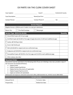


© Copyright 2026