
Operation Manual AxSun Solar Modules and Laminates for
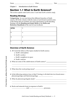
Operation Manual for AxSun Solar Modules and Laminates Translation of the original instruction manual for installers This manual applies to all products of the AxSun AX-P and AX-M series which are manufactured for stationary application. Version 2.0.2 AxSun Solar GmbH & Co. KG Ritter-Heinrich-Str. 1 88471 Laupheim-Baustetten Tel. +49 7392 / 96 96 850 Fax +49 7392 / 96 96 851 Email: [email protected] Internet: www.axsun.de Table of contents 1. Introduction ........................................................................................................................................................ 2 1.1. Intended use ................................................................................................................................................ 2 1.2. Safety information ....................................................................................................................................... 2 1.3. Malfunction ................................................................................................................................................. 2 2. Local conditions and site survey ......................................................................................................................... 2 2.1. Orientation and pitch .................................................................................................................................. 2 2.2. Regulations and standards .......................................................................................................................... 3 3. General safety instructions ................................................................................................................................. 3 3.1. Before start of work .................................................................................................................................... 3 3.2. General safety ............................................................................................................................................. 4 4. Installation........................................................................................................................................................... 4 4.1. Excerpt from data sheet (example) ............................................................................................................. 4 4.2. Installation options ...................................................................................................................................... 4 4.3. Alignment of the modules ........................................................................................................................... 4 4.4. Wind- and snow load ................................................................................................................................... 5 4.5. Mounting structure requirements .............................................................................................................. 5 4.6. Module installation ..................................................................................................................................... 5 4.7. Selection of the modules ............................................................................................................................. 5 4.8. Safety factor ................................................................................................................................................ 5 4.9. Series connection ........................................................................................................................................ 5 4.10. Parallel connection .................................................................................................................................... 6 4.11. Inverters .................................................................................................................................................... 6 4.12. Earthing ..................................................................................................................................................... 6 4.12.1. Functional earthing ............................................................................................................................ 6 4.12.2. Protective earthing ............................................................................................................................ 7 4.13. Electrical installation ................................................................................................................................ 7 4.13.1. Safety regulations .............................................................................................................................. 7 4.13.2. Cables and plug connectors ............................................................................................................... 7 5. Handling of the modules ..................................................................................................................................... 8 5.1. Transportation ............................................................................................................................................. 8 5.2. Storage ........................................................................................................................................................ 8 5.3. Back Sheet protection ................................................................................................................................. 8 6. Maintenance ....................................................................................................................................................... 8 6.1. Cleaning ....................................................................................................................................................... 8 6.2. Maintenance ............................................................................................................................................... 8 7. Decommissioning and Recycling ......................................................................................................................... 9 8. Disclaimer ............................................................................................................................................................ 9 Amendment Solar Laminates ................................................................................................................................ 10 1. Introduction ...................................................................................................................................................... 10 2. Intended use ..................................................................................................................................................... 10 3. Installaton instructions...................................................................................................................................... 10 AxSun Solar GmbH & Co. KG Ritter-Heinrich-Straße 1 88471 Laupheim-Baustetten - 1/12 - Tel. 07392/96 96 850 Fax 07392/96 96 851 [email protected] - www.axsun.de 1. Introduction 2. Local conditions and site survey We are pleased that you have decided on AxSun Solar modules for your PV-system. In order to maintain our high quality modules in good condition for many years, it is necessary to have them installed and maintained by skilled personnel. Read this instruction manual in its entirety and keep this manual in a safe place. AxSun Solar modules are proofed for use in moderate climatic conditions (IEC 61215). Operation temperature is from -40 °C to +85 °C. In order to avoid loss of power, all modules connected in series, should be installed in an allseason shadow-free area. Even partial shadowing results in losses of yield and should be avoided. Ventilation of the modules’ back side will prevent heat build-up which affects the energy yield. This instruction manual is addressed to installers and plant operators who are in charge of installation, commissioning and operating of AxSun Solar modules. It contains useful information to keep the photovoltaic system at its optimum over its entire lifespan. During installation work, follow all local laws and regulations regarding fire protection (see also paragraph 2.2 regulations and standards). The installation of a PV system may affect the fire safety of a building. Faulty installation may lead to fire hazard. For this reason, AxSun Solar modules shall be installed on suitable and fire resistant roofings, only. In case of fire, the fire fighters must have access to the PV system. The purpose of the following instruction is to help you to properly install the Axsun Solar modules. In certain cases please ask for expert advice to accommodate the local conditions. All applicable international, national, and local regulations, standards and requirements shall be followed. Generally, it is recommended to insure for your PVsystem. Solar modules are no explosion-protected equipment. Modules must not be installed in the vicinity of highly flammable gases, vapors or dusts (e.g. gas tanks, filling stations, paint spraying equipment). Modules must not be installed next to open flames and highly inflammable material. 1.1. Intended use AxSun Solar modules may only be used according to their suitability. The use for any other purpose is not allowed. The modules may not be technically altered. Failure to comply with this instruction manual will invalidate the module warranty. The modules mentioned in this instruction manual must not be used on vehicles of any kind and are not suitable for building integration and overhead glazing. Artificially concentrated sunlight shall not be directed on the modules. 1.2. Safety information AxSun Solar modules shall only be installed by qualified professionals. Keep children and animals away from the installation site. Inform people who are in the building about your work. Follow local and national regulations for photovoltaic systems (see also paragraph 2.2 regulations and standards). Failure to comply with the regulations can lead to personal injuries and material damages. This instruction manual is based on German law and regulations. Make sure that the modules will never be submerged in water or be exposed to continuous wetting (e.g. by fountains). Installation under water or close to fountains is not allowed. Exposure to salt or sulfur (sulfur sources, volcanoes) implies a risk of corrosion. A distance of 500 meters to an ocean shall be kept. AxSun Solar modules should not be affected by chemical emissions (e.g. chemical industries). 1.3. Malfunction 2.1. Orientation and pitch In case of a malfunction please call your local installer. Do not try to repair the system by yourself. In order to avoid yield losses, all modules connected in series should be arranged with the same orientation and pitch. The best orientation depends on the latitude. We recommend the use of suitable software tools. AxSun Solar GmbH & Co. KG Ritter-Heinrich-Straße 1 88471 Laupheim-Baustetten - 2/12 - Tel. 07392/96 96 850 Fax 07392/96 96 851 [email protected] - www.axsun.de BGV A2 / A3 Electrical systems and utilities 2.2. Regulations and standards This paragraph is based on German standards and regulations. This list is not intended to be exhaustive. Please observe your local regulations and laws. Please note that all valid standards, building regulations and safety regulations will be met before and during the installation procedure. The following regulations apply: BGV C22 Personal safety kit for fall protection BGV D36 Ladders and steps TRLV-2006 Technical regulations for the use of glazing with linear supports DIN VDE 0100 Setting up of power installations with rated voltage up to 1.000 Volt, all relevant parts, in particular T712 TRPV-2006 Technical regulations for the use of glazing with punctual supports VDE 0105 T100 Operation of electrical systems Regulations of the local utility company VDI 6012 Decentralized energy systems in buildings, in particular page 2, Photovoltaics 3. General safety instructions VDE 0298 T4 rubber-insolated wires Installation, maintenance, connection to the grid and dismantling must be carried out by trained and qualified personnel with approved training certificates for the respective specialist trade. Country-specific regulations have to be met (see paragraph 2.2). Non-compliance may result in damage and/or physical injury. DIN 18382 Electrical cable- and wiring systems in buildings DIN 18334 Carpenter- and timber work 3.1. Before start of work Take action against falls (scaffold, safety belts etc.) Wear protective clothing at all times during installation (safety shoes, insulation gloves, safety helmet etc.) and safety glasses while drilling, doing milling work and doing grinding work. Do not wear any metal jewelry while working on the photovoltaic system. DIN 18338 Roofing- and sealing work DIN 18339 Plumbing work DIN 18351 Work at façades Electrical works have to be carried out by using suitable tools for electrical works only. Tools and surroundings have to be dry. Solar modules and wiring have to be connected to dry plug connectors and dry bushes. DIN 18451 Work at scaffolds Technical connection conditions (TAB) in order to connect to the low voltage system of the utility companies. Solar modules start generating direct current even at diffused incidence of light. As soon as the modules are exposed to light they are voltagecarrying, presenting a serious danger. The voltage of a single module is less than 50V but connection of modules in series adds the voltage of each module. Parallel connection of the modules sums up the current (amperes). Although, the insulated plug connectors protect against accidental contact VDEW-regulation Power generation plant on low voltage regulations of the“ Berufsgenossenschaft der Bauwirtschaft / Dacharbeiten“ BGV A1 General regulations AxSun Solar GmbH & Co. KG Ritter-Heinrich-Straße 1 88471 Laupheim-Baustetten - 3/12 - Tel. 07392/96 96 850 Fax 07392/96 96 851 [email protected] - www.axsun.de the AxSun Solar modules must be covered by lightproof material before doing any kind of work. 4.1. Excerpt from data sheet (example) Basis data: 3.2. General safety Cells: polycrystalline solar cells (156 x 156 mm) Glass: 4 mm tempered Solar safety glass Frame: Anodized aluminium profile with hollow chamber and drainage holes, black or silver anodized Bypass-Diodes: 3 pieces Junction box: plastic, IP 65 type of protection cable, plug: 4mm² solar cable, 1.000 mm length, MC4-compatible Max. voltage: 1.000 V Max. return current: 15 A Temperature range: -40 °C to 85 °C Max. pressure load: 5.400 Pascal (pressure- and suction load), acc. to IEC 61215 Ed. 2 Application class: A, acc. to IEC 61730 Fire class : C, acc. to IEC 61730 Protection class: II Solar modules generate direct current (DC). When disconnecting an electric circuit carrying direct current, electric arcs can occur that may result in life-threatening injuries. Direct current electric arcs are not self-extinguishing. This may result in mortal burn and fire hazard. They can destroy connectors and contact parts. Please observe the following: Remove or open the AC circuit breaker of the inverter before you disconnect the inverter from the grid. Never isolate the solar generator from the inverter as long as the inverter is still connected to the grid. Temperature coefficient (in case of temperature change): Power: PMPP (Watt) Tk PMPP = -0,438 %/K Voltage: UOC (Volt) Tk UOC = -0,325 %/K Current: ISC (Ampere) Tk ISC = 0,045 %/K Switch off the inverter or disconnect it from the system and wait for the time period, specified by the manufacturer, to pass before you start your work. The high-voltage parts need some time to discharge. Please follow the instructions of the inverter manufacturer. 4.2. Installation options There are two approved installation options for AxSun solar modules. Panel format installation and landscape format installation always using clamps.The example shows a solar module AX-P60 with arrowheads mark the fixing points. Please arrange for faultless cable connections. Connect the cables seamlessly and keep them dry and clean. Do not plug any objects made of metal or other conducting material into the plugs or connectors. Damaged solar modules must not be used. Damaged glass or back sheets can cause hazardous voltage. Do not install or maintain solar modules during bad weather conditions like strong wind or rain. Make sure that the maximum open-circuit voltage of the connected solar modules does not exceed 1000 VDC (IEC 61215, Ed. 1 / 61730, Ed. 2) resp. 600 VDC (UL 1703) even at low temperatures and / or a radiation of more than 1000 W/m² For exact measurements of the fixing points please see the drawings on the relevant data sheet. For electrical data and further module details please also refer to the relevant data sheet. 4.3. Alignment of the modules 4. Installation Maintain a minimum tilt angle of 5°. Ensure that rain and melting snow can run off freely. No accumulation underneath the solar modules. Ensure that the drainage holes in the solar module Please note paragraphs 1.2 and 2.2 and 3. to 3.2 before starting your installation work. AxSun Solar GmbH & Co. KG Ritter-Heinrich-Straße 1 88471 Laupheim-Baustetten - 4/12 - Tel. 07392/96 96 850 Fax 07392/96 96 851 [email protected] - www.axsun.de frames are not covered. Ensure that there is no sealing of the drainage holes after installation. This way corrosion and damage by frost are prevented. The junction box must be at the upper sector of the module. Clamp width: ≥ 55 mm Clamp depth: ≥ 7 mm 2 Clamp surface area ≥ 400 mm (clamp depth x clamp width) 4.4. Wind- and snow load AxSun Solar modules are suitable for wind and snow loads up to 5400 Pa when installed properly according to this instruction manual. Clamps must fulfil the structural requirements of the installation site. 4.5. Mounting structure requirements Use of long-term stable clamps that securely fix the modules to the mounting structure. Mounting frames and clamps must be compatible. Requirements for the mounting structure are: 4.7. Selection of the modules Comply with local snow and wind loads. Only connect modules of the same type and the same power class to achieve optimal yield. Properly fastened to the ground, the roof or façade. 4.8. Safety factor Forces acting on the modules are transferred into the mounting substructure. Ensure that no mechanical stresses are generated on the module (e.g. caused by vibrations, twisting, or expansion). During normal operation, it may occur that the module provides a higher current and/or a higher voltage than that determined under standard test conditions. Therefore, please calculate a safety factor of 1.25 when Ensure sufficient rear ventilation of the modules. Determining the voltage design value (VOC) of the components Allows for stress free expansion and contraction due to temperature fluctuations. Determining the current design values of the conductors (ISC) and Ensure long-term stability. Determining the ratings of the control units connected to the solar module output. Ensure that no contact corrosion between different metals occur due to its electrochemical series. Please always refer to local requirements and regulations for the installation of electrical systems. 4.6. Module installation 4.9. Series connection Ensure the long-term stability of the modules. Install AxSun modules according to the above mentioned types. Ensure that the modules rest plane on the mounting system. The connected modules should be of the same power class. Please watch the sorting and tolerance range Voc and Vmpp on the relevant data sheet. Maintain a minimum distance of 10 mm between modules. Fasten the module with 4 clamps in the specified clamping area (see paragraph 4.2). Tighten clamps to a torque of 18 Nm. This way you avoid mechanical tension and twists. The connection of modules in series is only permitted up to the maximum system voltage as determined by the relevant data sheet. Bear in mind all possible operating conditions and all relevant technical standards and regulations. Requirements of the clamp system: AxSun Solar GmbH & Co. KG Ritter-Heinrich-Straße 1 88471 Laupheim-Baustetten - 5/12 - Tel. 07392/96 96 850 Fax 07392/96 96 851 [email protected] - www.axsun.de This ensures that the maximum system voltage, including all necessary safety margins, is not exceeded. 4.12. Earthing Warning! During the planning phase of the PV system bear in mind the voltage limit of the inverter when determining the string size. Wrong or faulty earhing increases fire hazard. 4.10. Parallel connection The connected modules must be of the same power class and type. The maximum reverse current rating, indicated on the data sheet, has to be observed. Modules may be damaged by the occurrence of reverse currents due to module defects, ground leak or defective insulation. 4.12.1. Functional earthing Functional earthing is absolutely essential when the installation of the system is < 500 m from the sea. Ensure that no hazard to life or physical condition occurs when direct earthing. Observe all regulations regarding fire protection and personal security. (see paragraph 2.2.). In order to install a safe functional earthing please: In order to limit reverse currents that may occur, we recommend using the following safety options: Version 1: Layout with a limited number of parallel connected strings. Without undertaking further string overcurrent protection, a maximum of three module strings may be operated in parallel on an inverter or MPP tracker. Only use inverters suitable for functional earthing. Only earth the negative pole of the system. Only use earthing components that are compatible with the inverter’s requirements. Version 2: Use of string diodes. When parallel connection is planned the strings can be protected against reverse current from the remaining parts of the system by using a corporate string diode. A maximum of three strings may use one corporate diode if three or more strings are supposed to be connected in parallel. Observe the earthing instructions given by the inverter manufacturer. Version 3: Layout with overcurrent protection devices. Install overcurrent protection devices in the positive and negative conductors of each string. Observe the overcurrent protection device specifications as indicated by the respective manufacturer as well as valid technical guidelines and standards. (see paragraph 2.2.). 4.11. Inverters Inverters with or without transformers may be used. AxSun Solar GmbH & Co. KG Ritter-Heinrich-Straße 1 88471 Laupheim-Baustetten - 6/12 - Tel. 07392/96 96 850 Fax 07392/96 96 851 [email protected] - www.axsun.de for the minus pole. 4.12.2. Protective earthing Meet and observe all local regulations and standards. Fix the protective earthing (according to the drawing) with a Parker screw to the earthing points. The earthing points are labelled with this symbol: Never open the junction box. Do not remove bypass diodes. 4.13.2. Cables and plug connectors When chosing and using cables and plug connectors please observe the following: Use Parker screws according to DIN 7981, Material A2, Size 5.5 mm x 16 mm. Use specified solar cables only. Use the same connector systems and connector systems compatible with the inverter within one solar system. Ensure that all electrical components are in a proper, dry and safe condition. Thus, you can avoid short circuits or hazardous touch voltage, caused by faulty or damaged cables. Ensure that the cabling is not under mechanical stress. Ensure for a tight connection of each of the plugs (in particular to the inverter). Observe that the plugs click together audibly. 4.13. Electrical installation Electrical work may only be performed by accredited and licensed electricians. 4.13.1. Safety regulations Disconnecting a DC circuit may cause electric arcs which can lead to life-threatening injuries. Never disconnect plugs under load. Ensure that the modules are disconnected at the inverter prior to separation. Make sure to observe the specified time intervals after switching off the inverter and before starting further works. High-voltage components need time to discharge. Cover the modules with light-blocking material during the work. Only this way are the modules reliably switched off. Never touch live contacts with bare hands. Only use dry, insulated tools for electrical work. Ensure that the polarity is correct. The plug connectors are labelled with plus symbol for the plus-pole and minus symbol AxSun Solar GmbH & Co. KG Ritter-Heinrich-Straße 1 88471 Laupheim-Baustetten - 7/12 - Tel. 07392/96 96 850 Fax 07392/96 96 851 [email protected] - www.axsun.de 5. Handling of the modules 6. Maintenance For completeness and visual lack of damage inspect your consignment directly after delivery. Any damages must be mentioned in writing on the lorry driver’s waybill AND to AxSun Solar. Inform your dealer of any damages immediately. AxSun Solar modules have been built for extreme longevity and need only little maintenance and cleaning. Dirt and grime are usually washed away by rain if the modules have been installed with appropriate pitch. If the modules are strongly contaminated by dirt (e.g. foliage, bird droppings, moss, soot etc.) and the rain is not efficient enough, additional cleaning may be necessary. Usually, snow slides off the modules, automatically. Handle the modules with care. Copy the serial numbers of the modules before installation and file them together with your documentation. Follow any safety instructions on the packaging and observe transport and storage instructions to avoid any damage of the modules. Always keep the electrical contacts dry and clean. Never disassemble the solar modules. Never open the junction box. Do not remove parts, symbols or type labels which have been fixed by the manufacturer. 6.1. Cleaning Clean AxSun Solar modules only when module temperature is between 10°C and 30°C e.g. early in the morning or late in the evening. Water temperature should not exceed 40°C. Do not clean the modules when there is a chance of frost and do not clean the modules when the temperature difference between module and air and water is too high. Use water which is deficient in lime or even better water without any lime (e.g. rain water). This will prevent lime spots on the module’s surface. Do not use scrubby cleaning tools or cleaning supplies and no tensides. Do not scratch off dirt. Do not rub off dirt when the modules are in dry condition. Use plenty of water and a soft cloth or sponge. Remove dirt from the mounting system. (foliage, bird’s nests, etc.). Observe the growth of grass around groundmounted PV-systems and cut the grass in due time to avoid shading. Beware of cables and stonechipping while mowing. Never step on the modules and do not subject the modules to any mechanical stress. While cleaning the modules please observe the warnings according to paragraph 2.2 regulations and standards. Do not enter the installation area alone and unsecured. We recommend entrusting a qualified contractor for the cleaning work. Ask your local installer for advice. 5.1. Transportation AxSun Solar modules must be transported and stored up-right. In order to avoid damages modules and packaging units must not be stacked. Assure that the modules do not tip over. It is recommended that the modules are carried by two persons. Never lift or move the module using the connection cables or junction box. Lift or move the module at the frame. Ensure that the modules do not yield or bend under their own weight during transportation. In order to avoid micro cracks the modules must not be stepped on and must not be subject to any mechanical stress. Do not drop the modules. 5.2. Storage Leave AxSun Solar modules up-right in their original packaging until installation. Store the modules securely in cool, dry and ventilated rooms. The packaging is not weatherproof. 5.3. Back Sheet protection Damaged back sheets may cause threat to life or physical condition. Therefore, protect the rear side of the modules from sharp objects, from colours and from glues. The back sheet protects the AxSun Solar module from weather conditions like moisture and water and provides electrical isolation. Damaged back sheets can cause delamination e.g. correction of the defects needs to be done exclusively by AxSun Solar. AxSun Solar GmbH & Co. KG Ritter-Heinrich-Straße 1 88471 Laupheim-Baustetten 6.2. Maintenance Disconnect the photovoltaic modules from other parts of the system by switching off the DC isolator before starting maintenance work. The system should be inspected by an installer annually. Ask your local installer for a service contract regarding the annual maintenance of your PV-system. This way you make sure that your PVsystem will be serviced regularly. Your installer will be able to fix damages or to prevent the system - 8/12 - Tel. 07392/96 96 850 Fax 07392/96 96 851 [email protected] - www.axsun.de from damages to guarantee a reliable operation of the system. This manual does not constitute a warranty of Axsun Solar GmbH & Co.KG. The scope of liability covers the contractual agreements of the framework or of assumed warranties of the framework only. There is no liability beyond the functionality and safety of the modules. The installer should check that: The cables are in excellent condition. The cables must be securely fastened with no mechanical stress subjected to the cables. Observe the instructions for all other system components which may be part of the complete PV-system. It may be necessary to carry out a structural analysis for the entire project. The modules are securely fastened. The contact resistances must be in excellent condition and securely fixed. Text and figures of this manual correspond to the current technical specifications at time of print. AxSun Solar reserves the right to make changes to the product, specifications or this manual without prior notice. All mechanical connections must be clean and undamaged, securely fixed and securely connected. All system components must be free of corrosion. This manual applies to the EU countries. Damages and abnormalities must be fixed immediately. In case that an AxSun Solar module has to be repaired please absolutely contact AxSun Solar. Never try to repair the solar modul by yourself. Improper repair work may cause damages which may lead to a breakdown of the electrical insulation in some years. Insufficient insulation may cause mortal danger. In order to avoid secondary damages and performance loss any damages should be reported and repaired immediately. Laupheim, June 2014 7. Decommissioning and Recycling Decommissioning of AxSun Solar modules shall only be executed by a qualified contractor. All local and national regulations and laws must be followed regarding the disposal of the modules. The customer is in charge of the disposal according to the regulations and laws. Please refer to a local disposal firm or to AxSun Solar. 8. Disclaimer This instruction manual only refers to solar modules manufactured by Axsun Solar. AxSun Solar assumes no liability for damages caused by non-observance of this manual. Please note that the installer company is liable regarding dimensioning and interconnection of the system and liable regarding observing the safety regulations during planning and installation of the PV-system. AxSun Solar GmbH & Co. KG Ritter-Heinrich-Straße 1 88471 Laupheim-Baustetten - 9/12 - Tel. 07392/96 96 850 Fax 07392/96 96 851 [email protected] - www.axsun.de Amendment Solar Laminates Following procedure is valid for all laminates of the AX-P and AX-M series Never lift or move or draw the laminates using the connection cables or junction box. 1. Introduction Observe the polarity of the laminates. (reverse connection may destroy the bypass diodes). We are pleased that you have decided on AxSun Solar laminates for your PV-system. In order to maintain our high quality laminates in good condition for many years, it is necessary to have them installed and maintained by skilled personnel. Read this instruction manual in its entirety and keep this manual in a safe place. The laminates must not be installed in an angle that allows water to run into the junction box (screw connections). The junction box must never be at the lower end of the laminate. The instruction manual for AxSun solar modules (part 1-8) is the basis for the amendment for solar laminates. All warning and safety and legal clauses listed therein also apply to the solar laminates. This amendment provides additional information about installation. Do not fix AxSun Solar-laminates at intervals. Use plane (large-scale) mounting systems. The laminates have to be put in the frames at least at their long sides (four-sided support surface). Laminates with width of more than 800 mm need additional backing. Moreover, these laminates need a four-sided support surface. Install the backings parallelly to the long sides of the laminates. Centralise the backings to avoid deflection of the laminates. The backing must not damage the back sheet. The design of the backing must be absorbed and large-scale in a way that potential wind and snow loads cannot damage the laminates. When determining the mounting system, your installer takes a significant impact on the longevity of the laminates. Improper installation may cause damage to the AxSun solar laminates for which AxSun Solar is not liable. 2. Intended use AxSun Solar laminates may only be used according to their suitability. The use for any other purpose is not allowed. The laminates may not be technically altered. Failure to comply with this instruction manual and in particular to safety regulations will invalidate the module warranty. This manual is for the use of laminates to fit into roof-integrated PVsystems Do not use glues or adhesive tapes to fix the laminates. Only use mechanical mounts and clamps to install the laminates. The edges of the laminates must never be in retained water. Make sure that water resp. snow can drain off. Please note that the edges of the laminates are shock-sensitive despite the implementation of high quality, tempered glasses. 3. Installaton instructions The laminates may not be stepped on Avoid build-up of heat on the back side of the laminates.. Observe the manufacturer instructions of the mounting system as well. The mounting system must be suitable for the installation of AxSun Solar-Laminates. The suitable mounting system must ensure that no mechanical tensions of the body assembly may be transferred into the laminates. Mechanical tensions cause cracks and deformations of the back sheet. AxSun Solar GmbH & Co. KG Ritter-Heinrich-Straße 1 88471 Laupheim-Baustetten Particularly, observe the distance between the laminates. It must not happen that the laminates touch each other due to possible extensions of the materials (min. 10mm AxSun Solar assumes no liability for electronic damages caused by heat build-up due to inadequate ventilation (heat accumulation beneath the laminate). Penetration of moisture e.g. by diffused melting water, may cause significant loss of power. - 10/12 - Tel. 07392/96 96 850 Fax 07392/96 96 851 [email protected] - www.axsun.de Delamination of laminates may be caused by: Heat or heat build-up due to a nonconforming mounting system. Cracks in the back sheet due to incorrect installation Retained water due to incorrect installation Make sure that all laminates are always properly installed. *** This manual applies to the EU countries. Laupheim, June 2014 AxSun Solar GmbH & Co. KG Ritter-Heinrich-Straße 1 88471 Laupheim-Baustetten - 11/12 - Tel. 07392/96 96 850 Fax 07392/96 96 851 [email protected] - www.axsun.de


© Copyright 2026