
CHARTER TOWNSHIP OF PLYMOUTH PLYMOUTH TOWNSHIP PARK PAVILION PROJECT MANUAL
PROJECT MANUAL for CHARTER TOWNSHIP OF PLYMOUTH PLYMOUTH TOWNSHIP PARK PAVILION OWNER: CHARTER TOWNSHIP OF PLYMOUTH 9955 N. HAGGERTY ROAD PLYMOUTH, MI 48170 PROJECT #14-286 APRIL 7, 2014 / 100% CD PKG 14-286 TABLE OF CONTENTS TOC - 1 Division Section Title Pages COVER TABLE OF CONTENTS………………………………………………………………………………………………………… .... 2 DIVISION 01 - GENERAL REQUIREMENTS 000000……….PROJECT IDENTIFICATION………………………………………………………………………………… .... 2 ADVERTISEMENT FOR BIDS .......................................................................................... .................................................... 2 003000……….REQUIRED BID SUBMISSION MATERIALS…………………………………………………………… ......... 2 003100............ CONTRACTOR INSURANCE REQUIREMENTS................................... .................................................... 2 010310……….BID FORM……………….…………………………………………………………… ......................................... 2 011000……….SUMMARY………………………………………………………………………................................................. 4 012100……….ALLOWANCES……………………………………………………………………… .......................................... 2 012300……….ALTERNATES……………………………………………………………………… ........................................... 2 012600……….CONTRACT MODIFICATION PROCEDURES……………………………………………………………… .. 4 012900……….PAYMENT PROCEDURES………………………………………………………………………………… ....... 4 013100……….PROJECT MANAGEMENT AND COORDINATION………………………………………………………...... 6 013200……….CONSTRUCTION PROGRESS DOCUMENTATION……………………………………………………….... 4 013300……….SUBMITTAL PROCEDURES………………………………………………………………………………… .... 8 014000……….QUALITY REQUIREMENTS………………………………………………………………………………… ..... 6 014200……….REFERENCES…………………………………………………………………………………………………..... 12 015000……….TEMPORARY FACILITIES AND CONTROLS…………………………………………………………………6 016000……….PRODUCT REQUIREMENTS………………………………………………………………………………… ... 6 017300……….EXECUTION……………………………………………………………………………………………………..... 8 017700……….CLOSEOUT PROCEDURES…………………………………………………………………………………..... 6 017823……….OPERATION AND MAINTENANCE DATA………………………………………………………………… ..... 4 017839……….PROJECT RECORD DOCUMENTS………………………………………………………………………… .... 4 DIVISION 02 – NOT APPLICABLE DIVISION 03 - CONCRETE 033000……….CAST-IN-PLACE CONCRETE………………………………………………………………………………….. 16 DIVISION 04 - MASONRY 042000……….UNIT MASONRY…………………………………………………………………………………………………. 12 DIVISION 05 - METALS 051200……….STRUCTURAL STEEL FRAMING……………………………………………………………………………… 6 DIVISION 06 - WOOD, PLASTICS, AND COMPOSITES 061053……… MISCELLANEOUS CARPENTRY……………………………………………………………………………… 4 061760……….PREFABRICATED WOOD TRUSSES………………………………………………………………………… 2 064023……….INTERIOR ARCHITECTURAL WOODWORK………………………………………………………………… 4 DIVISION 07 - THERMAL AND MOISTURE PROTECTION 071900……….MASONRY SEALERS & GRAFFITI CONTROL……………………………………………………………….4 072100……….BUILDING INSULATION………………………………………………………………………………………… 8 073100............ FIBERGLASS SHINGLES ........................................................................ .................................................... 10 073150............ VINYL SOFFIT .......................................................................................... .................................................... 2 074610............ SIDING ....................................................................................................... .................................................... 6 077100……….MANUFACTURED ROOF SPECIALITES ................................................ .................................................... 8 APRIL 4, 2014 / 100% CD PKG 14-286 TABLE OF CONTENTS TOC - 2 079200……….JOINT SEALANTS……………………………………………………………………………………………….. 6 DIVISION 08 - OPENINGS 081113……….STEEL DOORS AND FRAMES………………………………………………………………………………… 8 081416……….FLUSH WOOD DOORS…………………………………………………………………………………………. 4 083113……….ACCESS DOORS AND FRAMES………………………………………………………………………………. 4 084229……… AUTOMATIC ENTRANCES…………………………………………………………………………… .............. 8 085113……… ALUMINUM WINDOWS………………………………………………………………………………………….. 6 087100……….DOOR HARDWARE…...……………………………………………………………………………………… .... 6 088000……….GLAZING………………………………………………………………………………………………………… .. 8 DIVISION 09 - FINISHES 092216……….NON-STRUCTURAL METAL FRAMING………………………………………………………………………. 6 092900……….GYPSUM BOARD………………………………………………………………………………………………... 6 093000……….TILING……………………………………………………………………………………………………………… 4 095123……….ACOUSTICAL TILE CEILINGS…………………………………………………………………………………. 4 096513……….RESILIENT BASE AND ACCESSORIES……………………………………………………………………… 4 096816……… CARPET TILE…………………………………………………………………………………….. ....................... 4 099113............ EXTERIOR PAINTING .............................................................................. .................................................... 4 099123……….INTERIOR PAINTING……………………………………………………………………………………………. 6 DIVISION 10 - SPECIALTIES 101420............ INTERIOR SIGNAGE................................................................................ .................................................... 4 102113……….TOILET COMPARTMENTS……………………………………………………………………… ……………4 102800……….TOILET AND BATH ACCESSORIES…………………………………………………………………………... 2 104413……….FIRE EXTINGUISHER CABINETS……………………………………………………………………………... 4 104416……….FIRE EXTINGUISHERS…………………………………………………………………………………………. 2 DIVISIONS 11 THRU DIVISION 21 NOT APPLICABLE DIVISIONS 22 THRU 30 REFER TO PLUMBING, MECHANICAL AND ELECTRICAL DRAWING SETS DIVISION 31 – SITE AND INFRASTRUCTURE 312000............ EARTH MOVING ....................................................................................... .................................................... 8 312300............ UTILITY TRENCHING .............................................................................. .................................................... 4 329219............ HYDRO SEEDING .................................................................................... .................................................... 2 DIVISIONS 32 THRU DIVISION 42 NOT APPLICABLE APRIL 4, 2014 / 100% CD PKG 14-286 PROJECT IDENTIFICATION 000000-1 PROJECT IDENTIFICATION PROJECT: PLYMOUTH TOWNSHIP PARK PAVILION 46550 Ann Arbor Trail Plymouth, MI 48170 OWNER: CHARTER TOWNSHIP OF PLYMOUTH 9955 N. Haggerty Road Plymouth, MI 48170 ARCHITECT: D. S. WRIGHT & ASSOCIATES, P.C. 44456 Clare Blvd. Plymouth, MI 48170 734 377-4632 STRUCTURAL ENGINEER: PARADIS ASSOCIATES, INC. 313 Main Suite A Rochester, MI 48307 248 650-4908 BID DUE DATE: JULY 14, 2014; 2:00PM BID LOCATION: CHARTER TOWNSHIP OF PLYMOUTH TOWNSHIP CLERK’S OFFICE Attn: Nancy Conzelman, Clerk 9955 N. Haggerty Road Plymouth, MI 48170 END OF SECTION April 7, 2014 PARTNERS 05-108 BID FORM 00310-2 THIS PAGE INTENTIONALLY LEFT BLANK APRIL 25, 2005 / 100% CD PKG ADVERTISEMENT FOR BIDS Charter Township of Plymouth – Plymouth Township Park Pavilion Plymouth, Michigan Project # 14-286 The Charter Township of Plymouth will receive single prime sealed bids for the proposed Plymouth Township Park Pavilion located at 46550 Ann Arbor Trail, Plymouth, MI 48170. The bids will be due on or before Monday, July 14th at 2:00 PM. Bids received after this date and time or bids received via facsimile will not be accepted. Bids shall be submitted in a sealed envelope labeled “Plymouth Township Park Pavilion” to the Plymouth Township Clerk’s Office, attention Nancy Conzelman, Clerk, located at 9955 N. Haggerty Road, Plymouth, MI 48170. Submit two (2) complete copies of the bid submittal. Bids received will be publicly opened and read aloud starting at 2:05 PM on Monday, July 14, 2014. This project is partially funded with Land and Water Conservation Fund Grant and relevant State requirements apply. PUBLISHED: DATE: Plymouth Observer June 22nd, 2014 ONLINE: Electronic files (PDF files) will be available on the Charter Township of Plymouth website, http://plymouthtwp.org/Departments/Clerk/RFP.htm and the Michigan Inter-Governmental Trade Network, MITN at http://www.mitn.info. June 20th, 2014 DATE: A copy of the drawings and project manual will be available at the Clerks for public review. Contractors are required to comply with the Charter Township of Plymouth’s Drug and Alcohol Free Workplace Policy. A copy of the policy is available at the Township offices. Michigan State Act PA 517 of 2012, Iran Economic Sanctions Act, requires notification that Iranlinked businesses may not bid on this Contract. Successful bidders will be required to provide certification that they are not an Iran-linked business. Make proposals on the bid form supplied in the project manual. No oral or telegraphic proposals or modifications will be considered. Submit with each bid, a certified check or acceptable bid bond payable to Charter Township of Plymouth, in an amount equal to five percent (5%) of the total bid. Bidders are required to provide a Labor and Material Payment Bond and a Performance Bond for bids in the amount of $50,000 or more. Bids may not be withdrawn for a period of ninety (90) days after the scheduled time of opening bids, without the consent of the Owner. The Township reserves the right to reject any or all bids received and to waive any formalities in regard thereto. In addition, the Township reserves the right to evaluate bids on any basis determined by the Township to be in the best interest of the Township and to consider alternate bids if the low bidder(s) does not comply with the project requirements or are otherwise determined to be unqualified. Questions regarding contract documents may be directed, in writing to D. S. Wright & Associates, P.C., 44456 Clare Blvd., Plymouth, MI, 48170, Fax: 734 956-9090 or email at th [email protected]. Questions must be received no later than 5:00 pm July 7 , 2014. All questions and answers will be placed on the Township website and on the MITN website for public review. 14-286 REQUIRED BID SUBMISSION MATERIALS 003000 - 1 SECTION 003000 –REQUIRED BID SUBMISSION MATERIALS PART 1 - GENERAL 1.1 SUMMARY A. Following this page is the Bid Form. Bidder must completely fill out the Bid Form and submit (2) original copies, by the date and time specified. April 7, 2014 / 100% CD PKG 14-286 REQUIRED BID SUBMISSION MATERIALS 003000 - 2 THIS PAGE INTENTIONALLY LEFT BLANK April 7, 2014 / 100% CD PKG 14-286 CONTRACTOR INSURANCE REQUIREMENTS 003100 – 1 SECTION 003100 –CONTRACTOR INSURANCE REQUIREMENTS The contractor, and any and all of their subcontractors, shall not commence work under this contract until they have obtained the insurance required under this paragraph. All coverage shall be with insurance companies licensed and admitted to do business in the State of Michigan. All coverages shall be with insurance carriers acceptable to Charter Township of Plymouth. The limits required below do not limit the liability of the Contractor. All deductibles and SIRs are the responsibility of the Contractor. 1. Worker’s Compensation Insurance: The Contractor shall procure and maintain during the life of this contract, Worker’s Compensation Insurance, including Employers’ Liability Coverage, in accordance with all applicable statutes of the State of Michigan. 2. Commercial General Liability Insurance: The Contractor shall procure and maintain during the life of this contract, Commercial General Liability Insurance on an “Occurrence Basis” with limits of liability not less than $1,000,000 per occurrence and aggregate. Coverage shall include the following extensions: (A) Contractual Liability; (B) Products and Completed Operations; (C) Independent Contractors Coverage; (D) Broad Form General Liability Extensions or equivalent, if not already included ; (E) Deletion of all Explosion, Collapse, and Underground (XCU) Exclusions, if applicable. 3. Motor Vehicle Liability: The Contractor shall procure and maintain during the life of this contract Motor Vehicle Liability Insurance, including Michigan No-Fault Coverages, with limits of liability not less than $1,000,000 per occurrence combined single limit for Bodily Injury, and Property Damage. Coverage shall include all owned vehicles, all non-owned vehicles, and all hired vehicles. 4. Additional Insured: Commercial General Liability and Motor Vehicle Liability, as described above, shall include an endorsement stating the following shall be Additional Insureds: The Charter Township of Plymouth, all elected and appointed officials, all employees and volunteers, agents, all boards, commissions, and/or authorities and board members, including employees and volunteers thereof. It is understood and agreed by naming the Charter Township of Plymouth as additional insured, coverage afforded is considered to be primary and any other insurance the Charter Township of Plymouth may have in effect shall be considered secondary and/or excess. 5. Cancellation Notice: Worker’s Compensation Insurance, Commercial General Liability Insurance, and Motor Vehicle Liability Insurance, as described above, shall be endorsed to state the following: “It is understood and agreed Thirty (30) days, Ten (10) days for non-payment of premium, Advance Written Notice of Cancellation, NonRenewal, Reduction, and/or Material Change shall be sent to: (Supervisor Richard M. Reaume, Charter Township of Plymouth, 9955 N. Haggerty Road, Plymouth, MI 48170-4673). 6. Owners’ and Contractors’ Protective Liability: The Contractor shall procure and maintain during the life of this contract, a separate Owners’ and Contractors’ Protective Liability Policy with limits of liability not less than $1,000,000 per occurrence and aggregate. The Charter Township of Plymouth shall be “Named Insured” on said coverage. A thirty (30) day, ten (10) day for non-payment of premium, Notice of Cancellation shall be endorsed onto this policy. A per project aggregate on the General Liability policy, in lieu of this requirement, is acceptable. 7. Proof of Insurance Coverage: The Contractor shall provide the Charter Township of Plymouth at the time the contracts are returned by him/her for execution. The furnishing of the foregoing certificates shall not operate to relieve the Contractor or any Subcontractor from any liability or obligation for which he would otherwise be responsible April 7, 2014 / 100% CD PKG 14-286 CONTRACTOR INSURANCE REQUIREMENTS 003100 - 2 under Contract or by accepted practice. Certificates, as listed below, must include specific job by number of, name and location. The furnishing of: a. Two (2) copies of Certificate of Insurance for Worker’s Compensation Insurance; b. Two (2) copies of Certificate of Insurance for Commercial General Liability Insurance; c. Two (2) copies of Certificate of Insurance for Vehicle Liability Insurance; Note: If electronic copies are provided, no duplication of certificates or policies is necessary. 8. If any of the above coverages expire during the term of this contract, the Contractor shall deliver renewal certificates and/or policies to Charter Township of Plymouth at least ten (10) days prior to the expiration date. 9. Property Insurance: The Charter Township of Plymouth shall effect and maintain fire insurance including: vandalism rider with extended coverage upon the entire structure on which the work of this contract is to be done to the extent of one hundred percent (100%) of the insurable value thereof including: all items of work in or adjacent to the insured structure, of such items are included in the costs of the work, excluding mechanic's tools, equipment, scaffolding and other such items where capital value is not included in the cost of the work. Any less under said coverage is to be made adjustable with payment to the Charter Township of Plymouth as trustee for the insured and the Contractor and the Subcontractor as their interest may appear. Insurance coverage shall not be altered or terminated without a 30-day notification to Contractor and Subcontractor. APRIL 7, 2014 / 100% CD PKG 14-286 BID FORM 010310 - 1 BID FORM BID PROPOSAL FOR: CHARTER TOWNSHIP OF PLYMOUTH, PLYMOUTH TOWNSHIP PARK PAVILION BID TO: CHARTER TOWNSHIP OF PLYMOUTH CLERK, NANCY CONZELMAN 9955 N. Haggerty Road Plymouth, MI 48170 BID DUE DATE: JULY 14, 2014; 2:00pm BIDDERS NAME: ______________________________________________________________________ We have examined the Contract Documents for the proposed PLYMOUTH TOWNSHIP PARK PAVILION Project, as prepared by D.S. Wright & Associates, P.C. In accordance therewith, the undersigned proposes to furnish all labor and materials for construction as set forth in the Contract Documents, including the following Addenda, if any (fill in the addenda number, thus confirming receipt): Addendum Number ________ Addendum Number ________ Addendum Number ________ Addendum Number ________ 1. Accompanying the proposal is the required bid security, the same being subject to forfeiture in the event of default by the undersigned. 2. Bids may not be withdrawn for a period of ninety (90) days after the scheduled time of opening bids, without the consent of the Owner. The Township reserves the right to reject any or all bids received and to waive any formalities in regard thereto. In addition, the Township reserves the right to evaluate bids on any basis determined by the Township to be in the best interest of the Township and to consider alternate bids if the low bidder(s) do not comply with the project requirements or are otherwise determined to be unqualified. 4. I agree to complete the project(s) by the date listed in Specification Section 011000 – Summary, provided that a notice to proceed is issued within thirty (30) days. A. BASE BID: (Insert a base bid amount in the blanks provided). __________________________________________________Dollars $_____________________ (Written Out Amount) APRIL 7, 2014 / 100% CD PKG 14-286 BID FORM 010310 - 2 B. ALTERNATE CONSTRUCTION MANAGEMENT PROPOSAL: 1. Provide an alternate propose for Construction Management services in lieu of a General Contract Bid. Purpose of this alternate is to allow the Charter Township of Plymouth to purchase certain materials direct for installation by the Construction Manager Subcontractors. 2. Construction Management Proposal to include, but limited to: a. b. c. d. Provide a budget estimate based on the contract documents. Provide Construction Management Fee as a percentage of the cost of the work. Provide General Conditions Cost, Superintendant, on site costs, etc. Define each subcontractor’s scope of work and clarify subcontractor questions for a thorough understanding of the Project. e. Upon contract award, provide qualified bids for each subcontractor trade, minimum 3 bids each. Review the proposals and make recommendations to the Owner and Architect for contract awards. Write all agreements for Owners approval and provide the necessary certificates of insurance naming the Owner as additional insured. f. Refer to Division One for additional Construction Management requirements 3. BUDGET ESTIMATE: (Insert a budget bid amount in the blank provided). Dollars $ CONSTRUCTION MANAGEMENT FEE: GENERAL CONDITIONS: % (Insert a general conditions amount in the blank provided). Dollars $ C. SCHEDULE: Fill in proposed construction duration (in weeks) if different than that listed in Section 011000 to achieve substantial completion from Notice of Award. _________________ Weeks D. Company Name:_____________________________________________________________ Contact Name:______________________________________________________________ Signature:_____________________________Title__________________________________ Phone Number: _______________________ Fax Number: __________________________ Date:__________________ END OF BID FORM APRIL 7, 2014 / 100% CD PKG Email Address:______________________________ 14-286 SUMMARY 011000 - 1 SECTION 011000 - SUMMARY PART 1 - GENERAL 1.1 SUMMARY A. This Section includes the following: 1. 2. 3. 4. 5. 1.2 Work covered by the Contract Documents. Schedule. Work under other contracts. Use of the premises. Specification formats and conventions. WORK COVERED BY CONTRACT DOCUMENTS A. Project Identification: CHARTER TOWNSHIP OF PLYMOUTH – Plymouth Township Park Pavilion; D.S. Wright & Associates, P.C. project number 14-286. 1. B. Project Location: Plymouth Township Park, 46550 Ann Arbor Trail, Plymouth, MI 48170. Owner: CHARTER TOWNSHIP OF PLYMOUTH. 1. Owner's Representative: Mark Lewis, Chief Building Official, 734 354-3210 C. Architect: D.S. WRIGHT & ASSOCIATES, P.C., 44456 Clare Blvd, Plymouth, MI 41870. D. The Work consists of the following: 1. E. 1.3 The Work includes but is not limited to the following: a. Construction of new single story pavilion with restrooms, warming room, maintenance room, and utility attic. Project will be constructed under a single prime contract. SCHEDULE A. 1.4 All construction must be substantially complete and ready for occupancy no later than November 21, 2014. WORK UNDER OTHER CONTRACTS A. General: Cooperate fully with separate contractors so work on those contracts may be carried out smoothly, without interfering with or delaying work under this Contract. Coordinate the Work of this Contract with work performed under separate contracts. APRIL 7, 2014 / 100% CD PKG 14-286 SUMMARY 011000 - 2 B. Concurrent Work: Owner will award separate contract(s) for the following construction operations at Project site. Those operations will be conducted simultaneously with work under this Contract. 1. 1.5 Communications Cabling: A separate contract will be awarded to for communications cabling. The general contractor will be required to allow the Owner’s communications cabling contractor access to the project site and must account for this task in their project schedule. The general contractor must conduct coordination meetings with this contractor and the Owner to insure timely completion of work by both parties. USE OF PREMISES A. General: Contractor shall have limited use of premises for construction operations. Comply with schedule and work hours as designated above. Coordinate specifics with Owner. B. Use of Site: Limit use of premises to work in areas indicated. Do not disturb portions of Project site beyond areas in which the Work is indicated. Work areas shall be cleaned each day and ready for use and occupancy the following day. 1. Limits: Confine construction operations to work areas within the building and to immediate outside of the building areas. 2. Driveways and Entrances: Keep driveways, loading areas and entrances serving premises clear and available to Owner, Owner's employees, the General Public, and emergency vehicles at all times. Do not use these areas for parking or storage of materials. a. b. 1.6 Schedule deliveries to minimize use of driveways and entrances. Schedule deliveries to minimize space and time requirements for storage of materials and equipment on-site. SPECIFICATION FORMATS AND CONVENTIONS A. Specification Format: The Specifications are organized into Divisions and Sections using the 16-division format and CSI/CSC's "MasterFormat" numbering system. 1. B. Division 1: Sections in Division 1 govern the execution of the Work of all Sections in the Specifications. Specification Content: The Specifications use certain conventions for the style of language and the intended meaning of certain terms, words, and phrases when used in particular situations. These conventions are as follows: 1. Abbreviated Language: Language used in the Specifications and other Contract Documents is abbreviated. Words and meanings shall be interpreted as appropriate. Words implied, but not stated, shall be inferred as the sense requires. Singular words shall be interpreted as plural, and plural words shall be interpreted as singular where applicable as the context of the Contract Documents indicates. APRIL 7, 2014 / 100% CD PKG 14-286 SUMMARY 011000 - 3 2. Imperative mood and streamlined language are generally used in the Specifications. Requirements expressed in the imperative mood are to be performed by Contractor. Occasionally, the indicative or subjunctive mood may be used in the Section Text for clarity to describe responsibilities that must be fulfilled indirectly by Contractor or by others when so noted. a. 1.7 The words "shall," "shall be," or "shall comply with," depending on the context, are implied where a colon (:) is used within a sentence or phrase. MANUFACTURERS COMPLIANCE A. 1.8 Unless otherwise specified “all materials” shall be installed in strict accordance with the instructions of the instructions of the manufacturers of the material used, which instructions shall become a part of these specifications. EXCAVATION AND DEWATERING A. Excess spoils generated by Site, General, Mechanical, Plumbing, Electrical, or Concrete Contractors shall be retained on site and used to backfill excavations as directed by the General Contractor. Excess spoils are to be evenly distributed on site for rough or final grading B. The Contractor shall maintain all excavations and the building in generally dry condition as necessary. 1.9 SOIL BORINGS A. Soil Borings will be made available upon request. PART 2 - PRODUCTS (Not Used) PART 3 - EXECUTION (Not Used) END OF SECTION 011000 APRIL 7, 2014 / 100% CD PKG 14-286 SUMMARY 011000 - 4 THIS PAGE INTENTIONALLY LEFT BLANK APRIL 7, 2014 / 100% CD PKG 14-286 ALLOWANCES 012100 - 1 SECTION 012100 - ALLOWANCES PART 1 - GENERAL 1.1 SUMMARY A. This Section includes administrative and procedural requirements governing the following: 1. Lump-sum allowances. B. See Division 1 Section "Unit Prices" for procedures for using unit prices. C. See Division 1 Section "Quality Requirements" for procedures governing the use of allowances for testing and inspecting. 1.2 SELECTION AND PURCHASE A. At the earliest practical date after award of the Contract, advise the Architect of the date when final selection and purchase of each product or system described by an allowance must be completed to avoid delaying the Work. B. At Architect's request, obtain proposals for each allowance for use in making final selections. Include recommendations that are relevant to performing the Work. C. Purchase products and systems selected by Architect from the designated supplier. 1.3 SUBMITTALS A. Submit proposals for purchase of products or systems included in allowances, in the form specified for Change Orders. B. Submit invoices or delivery slips to show actual quantities of materials delivered to the site for use in fulfillment of each allowance. C. Coordinate and process submittals for allowance items in same manner as for other portions of the Work. 1.4 COORDINATION A. Coordinate allowance items with other portions of the Work. Furnish templates as required to coordinate installation. APRIL 7, 2014 / 100% CD PKG 14-286 ALLOWANCES 012100 - 2 1.5 LUMP-SUM ALLOWANCES A. 1.6 Unless otherwise indicated, Contractor's costs for receiving and handling at Project site, labor, installation, overhead and profit, and similar costs related to products and materials under allowance shall be included as part of the Contract Sum and not part of the allowance. UNUSED AMOUNTS A. Unused amounts shall be credited to Owner. PART 2 - PRODUCTS (Not Used) PART 3 - EXECUTION 3.1 EXAMINATION A. 3.2 Examine products covered by an allowance promptly on delivery for damage or defects. Return damaged or defective products to manufacturer for replacement. PREPARATION A. 3.3 Coordinate materials and their installation for each allowance with related materials and installations to ensure that each allowance item is completely integrated and interfaced with related work. SCHEDULE OF ALLOWANCES A. 3.4 None PERMITS A. A General Building Permit shall be applied for and will be provided by the Owner at no fee to the Contractor. Individual trades will be required to apply and pay for a permit for their individual work scope. END OF SECTION 012100 APRIL 7, 2014 / 100% CD PKG 14-286 CONTRACT MODIFICATION PROCEDURES 012600 - 1 SECTION 012600 - CONTRACT MODIFICATION PROCEDURES PART 1 - GENERAL 1.1 SUMMARY A. This Section specifies administrative and procedural requirements for handling and processing Contract modifications. B. See Division 1 Section "Allowances" for procedural requirements for handling and processing allowances. C. See Division 1 Section "Unit Prices" for administrative requirements for using unit prices. 1.2 MINOR CHANGES IN THE WORK A. 1.3 Architect will issue supplemental instructions authorizing Minor Changes in the Work, not involving adjustment to the Contract Sum or the Contract Time, on "Architect's Supplemental Instructions" form. PROPOSAL REQUESTS A. Owner-Initiated Proposal Requests: Architect will issue a detailed description of proposed changes in the Work that may require adjustment to the Contract Sum or the Contract Time. If necessary, the description will include supplemental or revised Drawings and Specifications. 1. 2. Proposal Requests issued by Architect are for information only. Do not consider them instructions either to stop work in progress or to execute the proposed change. Within seven (7) days after receipt of Proposal Request, submit a quotation estimating cost adjustments to the Contract Sum and the Contract Time necessary to execute the change. a. b. c. d. e. Include a list of quantities of products required or eliminated and unit costs, with total amount of purchases and credits to be made. If requested, furnish survey data to substantiate quantities. Indicate applicable taxes, delivery charges, equipment rental, and amounts of trade discounts. Include costs of labor and supervision directly attributable to the change. Include an updated Contractor's Construction Schedule that indicates the effect of the change, including, but not limited to, changes in activity duration, start and finish times, and activity relationship. Use available total float before requesting an extension of the Contract Time. Quotations submitted will be assumed to be complete. Contractor omissions submitted at a later date and deemed to be associated with said Proposal Request will not be considered and thus additional compensation for the omission will not be paid. APRIL 7, 2014 / 100% CD PKG 14-286 CONTRACT MODIFICATION PROCEDURES 012600 - 2 B. Contractor-Initiated Proposals: If latent or unforeseen conditions require modifications to the Contract, Contractor may propose changes by submitting a request for a change to Architect. 1. 2. 3. 4. 5. 6. C. 1.4 Include a statement outlining reasons for the change and the effect of the change on the Work. Provide a complete description of the proposed change. Indicate the effect of the proposed change on the Contract Sum and the Contract Time. Include a list of quantities of products required or eliminated and unit costs, with total amount of purchases and credits to be made. If requested, furnish survey data to substantiate quantities. Indicate applicable taxes, delivery charges, equipment rental, and amounts of trade discounts. Include costs of labor and supervision directly attributable to the change. Include an updated Contractor's Construction Schedule that indicates the effect of the change, including, but not limited to, changes in activity duration, start and finish times, and activity relationship. Use available total float before requesting an extension of the Contract Time. Comply with requirements in Division 1 Section "Product Requirements" if the proposed change requires substitution of one product or system for product or system specified. Proposal Request Form: Use AIA Document G709 for Proposal Requests. ALLOWANCES A. Allowance Adjustment: To adjust allowance amounts, base each Change Order proposal on the difference between purchase amount and the allowance, multiplied by final measurement of work-in-place. If applicable, include reasonable allowances for cutting losses, tolerances, mixing wastes, normal product imperfections, and similar margins. 1. 2. 3. 4. B. Include installation costs in purchase amount only where indicated as part of the allowance. If requested, prepare explanation and documentation to substantiate distribution of overhead costs and other margins claimed. Submit substantiation of a change in scope of work, if any, claimed in Change Orders related to unit-cost allowances. Owner reserves the right to establish the quantity of work-in-place by independent quantity survey, measure, or count. Submit claims for increased costs because of a change in scope or nature of the allowance described in the Contract Documents, whether for the Purchase Order amount or Contractor's handling, labor, installation, overhead, and profit. Submit claims within 21 days of receipt of the Change Order or Construction Change Directive authorizing work to proceed. Owner will reject claims submitted later than 21 days after such authorization. 1. 2. Do not include Contractor's or subcontractor's indirect expense in the Change Order cost amount unless it is clearly shown that the nature or extent of work has changed from what could have been foreseen from information in the Contract Documents. No change to Contractor's indirect expense is permitted for selection of higher- or lower-priced materials or systems of the same scope and nature as originally indicated. APRIL 7, 2014 / 100% CD PKG 14-286 CONTRACT MODIFICATION PROCEDURES 012600 - 3 1.5 CHANGE ORDER PROCEDURES A. 1.6 On Owner's approval of a Proposal Request, Architect will issue a Change Order for signatures of Owner and Contractor. CONSTRUCTION CHANGE DIRECTIVE A. Construction Change Directive: Architect may issue a Construction Change Directive. Construction Change Directive instructs Contractor to proceed with a change in the Work, for subsequent inclusion in a Change Order. 1. B. Construction Change Directive contains a complete description of change in the Work. It also designates method to be followed to determine change in the Contract Sum or the Contract Time. Documentation: Maintain detailed records on a time and material basis of work required by the Construction Change Directive. 1. After completion of change, submit an itemized account and supporting data necessary to substantiate cost and time adjustments to the Contract. PART 2 - PRODUCTS (Not Used) PART 3 - EXECUTION (Not Used) END OF SECTION 012600 APRIL 7, 2014 / 100% CD PKG 14-286 CONTRACT MODIFICATION PROCEDURES 012600 - 4 THIS PAGE INTENIONALLY LEFT BLANK APRIL 7, 2014 / 100% CD PKG 14-286 PAYMENT PROCEDURES 012900 - 1 SECTION 012900 - PAYMENT PROCEDURES PART 1 - GENERAL 1.1 SUMMARY A. 1.2 This Section specifies administrative and procedural requirements necessary to prepare and process Applications for Payment. SCHEDULE OF VALUES A. Coordination: Coordinate preparation of the Schedule of Values with preparation of Contractor's Construction Schedule. 1. 2. B. Correlate line items in the Schedule of Values with other required administrative forms and schedules, including Application for Payment forms with Continuation Sheets, Submittals Schedule and Contractor's Construction Schedule. Submit the Schedule of Values to Architect at earliest possible date but no later than seven days after signing of contract. Format and Content: Use the Project Manual table of contents as a guide to establish line items for the Schedule of Values. Provide at least one line item for each Specification Section. 1. Identification: Include the following Project identification on the Schedule of Values: a. b. c. d. e. 2. 3. 4. 5. 6. 7. Project name and location. Name of Architect. Architect's project number. Contractor's name and address. Date of submittal. Submit draft of AIA Document G703 Continuation Sheets. Provide a breakdown of the Contract Sum in enough detail to facilitate continued evaluation of Applications for Payment and progress reports. Coordinate with the Project Manual table of contents. Provide several line items for principal subcontract amounts, where appropriate. Include separate line items under required principal subcontracts for operation and maintenance manuals, punch list activities, Project Record Documents, and demonstration and training in the amount of 5 percent of the Contract Sum. Round amounts to nearest whole dollar; total shall equal the Contract Sum. Provide a separate line item in the Schedule of Values for each part of the Work where Applications for Payment may include materials or equipment purchased or fabricated and stored, but not yet installed. Provide separate line items in the Schedule of Values for initial cost of materials, as well as the labor for each line item. Allowances: Provide a separate line item in the Schedule of Values for each allowance. Show line-item value of unit-cost allowances, as a product of the unit cost, multiplied by measured quantity. Use information indicated in the Contract Documents to determine quantities. APRIL 7, 2014 / 100% CD PKG 14-286 PAYMENT PROCEDURES 012900 - 2 8. Each item in the Schedule of Values and Applications for Payment shall be complete. Include total cost and proportionate share of general overhead and profit for each item. a. 9. 1.3 Temporary facilities and other major cost items that are not direct cost of actual work-inplace may be shown either as separate line items in the Schedule of Values or distributed as general overhead expense, at Contractor's option. Schedule Updating: Update and resubmit the Schedule of Values before the next Applications for Payment when Change Orders or Construction Change Directives result in a change in the Contract Sum. APPLICATIONS FOR PAYMENT A. Each Application for Payment shall be consistent with previous applications and payments as certified by Architect and paid for by Owner. 1. Initial Application for Payment, Application for Payment at time of Substantial Completion, and final Application for Payment involve additional requirements. B. Payment Application Times: The date for each progress payment is indicated in the Agreement between Owner and Contractor. The period of construction Work covered by each Application for Payment is the period indicated in the Agreement. C. Payment Application Times: Progress payments shall be submitted to Architect by the first day of the month. The period covered by each Application for Payment is one month, ending on the last day of the previous month. D. Payment Application Forms: Use AIA Document G702 and AIA Document G703 Continuation Sheets as form for Applications for Payment. E. Application Preparation: Complete every entry on form. Notarize and execute by a person authorized to sign legal documents on behalf of Contractor. Architect will return incomplete applications without action. 1. 2. F. Transmittal: Submit (4) signed and notarized original copies of each Application for Payment to Architect by a method ensuring receipt within 24 hours. Three copies shall include waivers of lien and similar attachments. 1. G. Entries shall match data on the Schedule of Values and Contractor's Construction Schedule. Use updated schedules if revisions were made. Include amounts of Change Orders and Construction Change Directives issued before last day of construction period covered by application. Transmit each copy with a transmittal form listing attachments and recording appropriate information about application. Waivers of Mechanic's Lien: With each Application for Payment, submit waivers of mechanic's lien from every entity who is lawfully entitled to file a mechanic's lien arising out of the Contract and related to the Work covered by the payment. APRIL 7, 2014 / 100% CD PKG 14-286 PAYMENT PROCEDURES 012900 - 3 1. 2. 3. 4. H. Initial Application for Payment: Administrative actions and submittals that must precede or coincide with submittal of first Application for Payment include the following: 1. 2. 3. 4. 5. 6. 7. 8. 9. 10. 11. 12. I. List of subcontractors. Schedule of Values. Contractor's Construction Schedule (preliminary if not final). Schedule of unit prices. Submittals Schedule (preliminary if not final). List of Contractor's staff assignments. List of Contractor's principal consultants. Copies of building permits. Copies of authorizations and licenses from authorities having jurisdiction for performance of the Work. Initial progress report. Report of preconstruction conference. Certificates of insurance and insurance policies. Application for Payment at Substantial Completion: After issuing the Certificate of Substantial Completion, submit an Application for Payment showing 100 percent completion for portion of the Work claimed as substantially complete. 1. 2. J. Submit partial waivers on each item for amount requested in previous application, after deduction for retainage, on each item. When an application shows completion of an item, submit final or full waivers. Owner reserves the right to designate which entities involved in the Work must submit waivers. Waiver Forms: Submit waivers of lien on forms, executed in a manner acceptable to Owner. Include documentation supporting claim that the Work is substantially complete and a statement showing an accounting of changes to the Contract Sum. This application shall reflect Certificates of Partial Substantial Completion issued previously for Owner occupancy of designated portions of the Work. Final Payment Application: Submit final Application for Payment with releases and supporting documentation not previously submitted and accepted, including, but not limited, to the following: 1. 2. 3. 4. 5. 6. 7. 8. Evidence of completion of Project closeout requirements. Insurance certificates for products and completed operations where required and proof that taxes, fees, and similar obligations were paid. Updated final statement, accounting for final changes to the Contract Sum. AIA Document G706, "Contractor's Affidavit of Payment of Debts and Claims." AIA Document G706A, "Contractor's Affidavit of Release of Liens." AIA Document G707, "Consent of Surety to Final Payment." Evidence that claims have been settled. Final meter readings for utilities, a measured record of stored fuel, and similar data as of date of Substantial Completion or when Owner took possession of and assumed responsibility for corresponding elements of the Work. APRIL 7, 2014 / 100% CD PKG 14-286 PAYMENT PROCEDURES 012900 - 4 PART 2 - PRODUCTS (Not Used) PART 3 - EXECUTION (Not Used) END OF SECTION 012900 APRIL 7, 2014 / 100% CD PKG 14-286 PROJECT MANAGEMENT AND COORDINATION 013100 - 1 SECTION 013100 - PROJECT MANAGEMENT AND COORDINATION PART 1 - GENERAL 1.1 SUMMARY A. This Section includes administrative provisions for coordinating construction operations on Project including, but not limited to, the following: 1. 2. 3. B. 1.2 Coordination Drawings. Project meetings. Requests for Interpretation (RFIs). See Division 1 Section "Execution Requirements" for procedures for coordinating general installation and field-engineering services, including establishment of benchmarks and control points. DEFINITIONS A. 1.3 RFI: Request from Contractor seeking interpretation or clarification of the Contract Documents. COORDINATION A. Coordination: Coordinate construction operations included in different Sections of the Specifications to ensure efficient and orderly installation of each part of the Work. Coordinate construction operations, included in different Sections that depend on each other for proper installation, connection, and operation. 1. 2. 3. 4. B. Prepare memoranda for distribution to each party involved, outlining special procedures required for coordination. Include such items as required notices, reports, and list of attendees at meetings. 1. C. Schedule construction operations in sequence required to obtain the best results where installation of one part of the Work depends on installation of other components, before or after its own installation. Coordinate installation of different components with other contractors to ensure maximum accessibility for required maintenance, service, and repair. Make adequate provisions to accommodate items scheduled for later installation. Where availability of space is limited, coordinate installation of different components to ensure maximum performance and accessibility for required maintenance, service, and repair of all components, including mechanical and electrical. Prepare similar memoranda for Owner and separate contractors if coordination of their Work is required. Administrative Procedures: Coordinate scheduling and timing of required administrative procedures with other construction activities and activities of other contractors to avoid conflicts and to ensure orderly progress of the Work. Such administrative activities include, but are not limited to, the following: APRIL 7, 2014 / 100% CD PKG 14-286 PROJECT MANAGEMENT AND COORDINATION 013100 - 2 1. 2. 3. 4. 5. 6. 7. 8. 9. 1.4 Preparation of Contractor's Construction Schedule. Preparation of the Schedule of Values. Installation and removal of temporary facilities and controls. Delivery and processing of submittals. Progress meetings. Pre-installation conferences. Project closeout activities. Startup and adjustment of systems. Project closeout activities. SUBMITTALS A. Coordination Drawings: Prepare Coordination Drawings showing maximum utilization of space for efficient installation of different components and to coordinate the installation of products and materials fabricated by separate entities. 1. Content: Project-specific information, drawn accurately to scale. Do not base Coordination Drawings on reproductions of the Contract Documents or standard printed data. Include the following information, as applicable: a. b. 2. 3. 4. 1.5 Indicate functional and spatial relationships of components of all architectural, structural, civil, mechanical, and electrical systems. Indicate dimensions shown on the Contract Drawings and make specific note of dimensions that appear to be in conflict with submitted equipment and minimum clearance requirements. Provide alternate sketches to Architect for resolution of such conflicts. Minor dimension changes and difficult installations will not be considered changes to the Contract. Sheet Size: At least 24 by 36 inches but no larger than 24 by 36 inches. Number of Copies: Submit five (5) opaque copies of each submittal. Architect will retain one copy. Refer to individual Sections for Coordination Drawing requirements for Work in those Sections. PROJECT MEETINGS A. General: Schedule and conduct meetings and conferences at Project site. 1. 2. 3. B. Attendees: Inform participants and others involved, and individuals whose presence is required, of date and time of each meeting. Notify Owner and Architect of scheduled meeting dates and times. Agenda: Prepare the meeting agenda. Distribute the agenda to all invited attendees. Minutes: Record significant discussions and agreements achieved. Distribute the meeting minutes to everyone concerned, including Owner and Architect, within three days of the meeting. Preconstruction Conference: Schedule a preconstruction conference before starting construction, at a time convenient to Owner and Architect, but no later than (10) ten days after execution of the Agreement. Hold the conference at Project site or another convenient location. Conduct the meeting to review responsibilities and personnel assignments. APRIL 7, 2014 / 100% CD PKG 14-286 PROJECT MANAGEMENT AND COORDINATION 013100 - 3 1. 2. Attendees: Authorized representatives of Owner, Architect, and their consultants; Contractor and its superintendent; major subcontractors; suppliers; and other concerned parties shall attend the conference. All participants at the conference shall be familiar with Project and authorized to conclude matters relating to the Work. Agenda: Discuss items of significance that could affect progress, including the following: a. b. c. d. e. f. g. h. i. j. k. l. m. n. o. p. q. r. s. t. u. v. 3. C. Tentative construction schedule. Critical work sequencing and long-lead items. Designation of key personnel and their duties. Procedures for processing field decisions and Change Orders. Procedures for RFIs. Procedures for testing and inspecting. Procedures for processing Applications for Payment. Distribution of the Contract Documents. Submittal procedures. Preparation of Record Documents. Use of the premises. Work restrictions. Owner's occupancy requirements. Responsibility for temporary facilities and controls. Construction waste management and recycling. Parking availability. Office, work, and storage areas. Equipment deliveries and priorities. First aid. Security. Progress cleaning. Working hours. Minutes: Record and distribute meeting minutes. Pre-installation Conferences: Conduct a pre-installation conference at Project site before each construction activity that requires coordination with other construction. 1. 2. Attendees: Installer and representatives of manufacturers and fabricators involved in or affected by the installation and its coordination or integration with other materials and installations that have preceded or will follow, shall attend the meeting. Advise Architect of scheduled meeting dates. Agenda: Review progress of other construction activities and preparations for the particular activity under consideration, including requirements for the following: a. b. c. d. e. f. g. h. i. The Contract Documents. Options. Related RFIs. Related Change Orders. Purchases. Deliveries. Submittals. Review of mockups. Possible conflicts. APRIL 7, 2014 / 100% CD PKG 14-286 PROJECT MANAGEMENT AND COORDINATION 013100 - 4 j. k. l. m. n. o. p. q. r. s. t. u. v. w. x. y. 3. 4. 5. D. Compatibility problems. Time schedules. Weather limitations. Manufacturer's written recommendations. Warranty requirements. Compatibility of materials. Acceptability of substrates. Temporary facilities and controls. Space and access limitations. Regulations of authorities having jurisdiction. Testing and inspecting requirements. Installation procedures. Coordination with other work. Required performance results. Protection of adjacent work. Protection of construction and personnel. Record significant conference discussions, agreements, and disagreements, including required corrective measures and actions. Reporting: Distribute minutes of the meeting to each party present and to parties who should have been present. Do not proceed with installation if the conference cannot be successfully concluded. Initiate whatever actions are necessary to resolve impediments to performance of the Work and reconvene the conference at earliest feasible date. Progress Meetings: Conduct progress meetings at weekly intervals. Coordinate dates of meetings with preparation of payment requests. 1. 2. Attendees: In addition to representatives of Owner and Architect, each contractor, subcontractor, supplier, and other entity concerned with current progress or involved in planning, coordination, or performance of future activities shall be represented at these meetings. All participants at the conference shall be familiar with Project and authorized to conclude matters relating to the Work. Agenda: Review and correct or approve minutes of previous progress meeting. Review other items of significance that could affect progress. Include topics for discussion as appropriate to status of Project. a. Contractor's Construction Schedule: Review progress since the last meeting. Determine whether each activity is on time, ahead of schedule, or behind schedule, in relation to Contractor's Construction Schedule. Determine how construction behind schedule will be expedited; secure commitments from parties involved to do so. Discuss whether schedule revisions are required to ensure that current and subsequent activities will be completed within the Contract Time. 1) b. Review schedule for next period. Review present and future needs of each entity present, including the following: 1) 2) APRIL 7, 2014 / 100% CD PKG Interface requirements. Sequence of operations. 14-286 PROJECT MANAGEMENT AND COORDINATION 013100 - 5 3) 4) 5) 6) 7) 8) 9) 10) 11) 12) 13) 14) 15) 16) 17) 18) 19) 20) 3. 4. Minutes: Record the meeting minutes. Reporting: Distribute minutes of the meeting to each party present and to parties who should have been present. a. 1.6 Status of submittals. Deliveries. Off-site fabrication. Access. Site utilization. Temporary facilities and controls. Work hours. Hazards and risks. Progress cleaning. Quality and work standards. Status of correction of deficient items. Field observations. RFIs. Status of proposal requests. Pending changes. Status of Change Orders. Pending claims and disputes. Documentation of information for payment requests. Schedule Updating: Revise Contractor's Construction Schedule after each progress meeting where revisions to the schedule have been made or recognized. Issue revised schedule concurrently with the report of each meeting. REQUESTS FOR INTERPRETATION (RFIs) A. Procedure: Immediately on discovery of the need for interpretation of the Contract Documents, and if not possible to request interpretation at Project meeting, prepare and submit an RFI in the form specified. 1. 2. 3. B. RFIs shall originate with Contractor. RFIs submitted by entities other than Contractor will be returned with no response. Coordinate and submit RFIs in a prompt manner so as to avoid delays in Contractor's work or work of subcontractors. Submit RFIs on Architect’s form provided. Transmit via e-mail. Content of the RFI: Include a detailed, legible description of item needing interpretation and the following: 1. 2. 3. 4. 5. 6. 7. 8. Project name. Date. Name of Contractor. Name of Architect. RFI number, numbered sequentially. Specification Section number and title and related paragraphs, as appropriate. Drawing number and detail references, as appropriate. Field dimensions and conditions, as appropriate. APRIL 7, 2014 / 100% CD PKG 14-286 PROJECT MANAGEMENT AND COORDINATION 013100 - 6 9. 10. 11. C. Hard-Copy RFIs: Use Architect’s form. 1. D. Contractor's suggested solution(s). If Contractor's solution(s) impact the Contract Time or the Contract Sum, Contractor shall state impact in the RFI. Contractor's signature. Attachments: Include drawings, descriptions, measurements, photos, Product Data, Shop Drawings, and other information necessary to fully describe items needing interpretation. Identify each page of attachments with the RFI number and sequential page number. Architect's Action: Architect will review each RFI, determine action required, and return it. Allow ten (10) days for Architect's response for each RFI. RFIs received after 1:00 p.m. will be considered as received the following working day. In some cases, a response may take longer than seven (7) days. Architect will notify Contractor within ten (10) days if additional time is needed. 1. The following RFIs will be returned without action: a. b. c. d. e. f. 2. 3. Requests for approval of submittals. Requests for approval of substitutions. Requests for coordination information already indicated in the Contract Documents. Requests for adjustments in the Contract Time or the Contract Sum. Requests for interpretation of Architect's actions on submittals. Incomplete RFIs or RFIs with numerous errors. Architect's action may include a request for additional information, in which case Architect's time for response will start again. Architect's action on RFIs that may result in a change to the Contract Time or the Contract Sum may be eligible for Contractor to submit Change Proposal according to Division 1 Section "Contract Modifications." a. If Contractor believes the RFI response warrants change in the Contract Time or the Contract Sum, notify Architect in writing within seven (7) days of receipt of the RFI response. E. On receipt of Architect's action, update the RFI log and immediately distribute the RFI response to affected parties. Review response and notify Architect within seven (7) days if Contractor disagrees with response. F. RFI Log: Prepare, maintain, and submit a tabular log of RFIs organized by the RFI number. Submit log weekly. Long shall be submitted to Architect two (2) days prior to regular progress meetings. Include the following: 1. 2. 3. 4. 5. 6. 7. Project name. Name and address of Contractor. Name and address of Architect. RFI number including RFIs that were dropped and not submitted. RFI description. Date the RFI was submitted. Date Architect's response was received. APRIL 7, 2014 / 100% CD PKG 14-286 PROJECT MANAGEMENT AND COORDINATION 013100 - 7 8. 9. Identification of related Minor Change in the Work, Construction Change Directive, and Proposal Request, as appropriate. Identification of related Field Order, Work Change Directive, and Proposal Request, as appropriate. PART 2 - PRODUCTS (Not Used) PART 3 - EXECUTION (Not Used) END OF SECTION 013100 APRIL 7, 2014 / 100% CD PKG 14-286 PROJECT MANAGEMENT AND COORDINATION 013100 - 8 THIS PAGE INTENTIONALLY LEFT BLANK APRIL 7, 2014 / 100% CD PKG 14-286 CONSTRUCTION PROGRESS DOCUMENTATION 013200 - 1 SECTION 013200 - CONSTRUCTION PROGRESS DOCUMENTATION PART 1 - GENERAL 1.1 SUMMARY A. This Section includes administrative and procedural requirements for documenting the progress of construction during performance of the Work, including the following: 1. 2. 3. 4. B. 1.2 Contractor's Construction Schedule. Submittals Schedule. Daily construction reports. Field condition reports. See Division 1 Section "Payment Procedures" for submitting the Schedule of Values. DEFINITIONS A. Activity: A discrete part of a project that can be identified for planning, scheduling, monitoring, and controlling the construction project. Activities included in a construction schedule consume time and resources. 1. 2. 3. Critical activities are activities on the critical path. They must start and finish on the planned early start and finish times. Predecessor Activity: An activity that precedes another activity in the network. Successor Activity: An activity that follows another activity in the network. B. CPM: Critical path method, which is a method of planning and scheduling a construction project where activities are arranged based on activity relationships. Network calculations determine when activities can be performed and the critical path of Project. C. Critical Path: The longest connected chain of interdependent activities through the network schedule that establishes the minimum overall Project duration and contains no float. D. Float: The measure of leeway in starting and completing an activity. E. Fragnet: A partial or fragmentary network that breaks down activities into smaller activities for greater detail. F. Major Area: A story of construction, a separate building, or a similar significant construction element. 1.3 SUBMITTALS A. Submittals Schedule: Submit three (3) copies of schedule. Arrange the following information in a tabular format: 1. Scheduled date for first submittal. April 7, 2014 / 100% CD PKG 14-286 CONSTRUCTION PROGRESS DOCUMENTATION 013200 - 2 2. Specification Section number and title. 3. 4. 5. 6. Submittal category (action or informational). Name of subcontractor. Description of the Work covered. Scheduled date for Architect's final release or approval. B. Contractor's Construction Schedule: Submit two (2) opaque copies of initial schedule, large enough to show entire schedule for entire construction period. C. Daily Construction Reports: Submit two (2) copies at bi-weekly intervals. D. Field Condition Reports: Submit two (2) copies at time of discovery of differing conditions. 1.4 COORDINATION A. Coordinate preparation and processing of schedules and reports with performance of construction activities and with scheduling and reporting of separate contractors. B. Coordinate Contractor's Construction Schedule with the Schedule of Values, list of subcontracts, Submittals Schedule, progress reports, payment requests, and other required schedules and reports. 1. 2. Secure time commitments for performing critical elements of the Work from parties involved. Coordinate each construction activity in the network with other activities and schedule them in proper sequence. PART 2 - PRODUCTS 2.1 SUBMITTALS SCHEDULE A. Preparation: Submit a schedule of submittals, arranged in chronological order by dates required by construction schedule. Include time required for review, resubmittal, ordering, manufacturing, fabrication, and delivery when establishing dates. 1. 2. 2.2 Coordinate Submittals Schedule with list of subcontracts, the Schedule of Values, and Contractor's Construction Schedule. Submit concurrently with the first complete submittal of Contractor's Construction Schedule. CONTRACTOR'S CONSTRUCTION SCHEDULE, GENERAL A. Time Frame: Extend schedule from date established for the Notice of Award to date of Final Completion. B. Activities: Treat each story or separate area as a separate numbered activity for each principal element of the Work. Comply with the following: April 7, 2014 / 100% CD PKG 1. 2. Procurement Activities: Include procurement process activities for the following long lead items and major items, requiring a cycle of more than 60 days, as separate activities in schedule. Procurement cycle activities include, but are not limited to, submittals, approvals, purchasing, fabrication, and delivery. a. CMU Veneer. b. Structural smooth faced and regular CMU c. Structural Steel and other Structural Components d. Prefabricated Columns e. Aluminum Framing, Aluminum Windows and Glazing f. Fiber cement siding and trim. g. Shingles and fascias. h. Toilet Partitions i. Millwork and Counter Tops j. Porcelain Tile, Carpet, Base k. Doors and Hardware l. Mechanical Equipment m. Plumbing Fixtures n. Lighting Fixtures o. Electrical Equipment p. Communications and Data Equipment 3. Submittal Review Time: Include review and resubmittal times indicated in Division 1 Section "Submittal Procedures" in schedule. Coordinate submittal review times in Contractor's Construction Schedule with Submittals Schedule. Startup and Testing Time: Include not less than 14 days for startup and testing. Substantial Completion: Indicate completion in advance of date established for Substantial Completion, and allow time for Architect's administrative procedures necessary for certification of Substantial Completion. 4. 5. C. Constraints: Include constraints and work restrictions indicated in the Contract Documents and as follows in schedule, and show how the sequence of the Work is affected. 1. 2. 3. 4. 5. D. 14-286 CONSTRUCTION PROGRESS DOCUMENTATION 013200 - 3 Activity Duration: Define activities so no activity is longer than twenty (20) days, unless specifically allowed by Architect. Phasing: Arrange list of activities on schedule by phase. Work under More Than One Contract: Include a separate activity for each contract. Work by Owner’s Contractors: Include a separate activity for each portion of the Work performed by Owner’s Contractors. Work Restrictions: Show the effect of the following items on the schedule: a. Seasonal variations. Work Stages: Indicate important stages of construction for each major portion of the Work. Milestones: Include milestones indicated in the Contract Documents in schedule, including, but not limited to, the Notice to Proceed, Substantial Completion, Final Completion, and all building inspections (rough and final) as required by the Authorities having jurisdiction. April 7, 2014 / 100% CD PKG 14-286 CONSTRUCTION PROGRESS DOCUMENTATION 013200 - 4 E. Contract Modifications: For each proposed contract modification and concurrent with its submission, prepare a time-impact analysis using fragnets to demonstrate the effect of the proposed change on the overall project schedule. 2.3 CONTRACTOR'S CONSTRUCTION SCHEDULE (GANTT CHART) A. 2.4 Gantt-Chart Schedule: Submit a comprehensive, fully developed, horizontal Gantt-chart-type, Contractor's Construction Schedule within twenty-one (21) days of date established for the Notice of Award. Base schedule on the Preliminary Construction Schedule and whatever updating and feedback was received since the start of Project. REPORTS A. Daily Construction Reports: Prepare a daily construction report recording the following information concerning events at Project site: 1. 2. 3. 4. 5. 6. 7. 8. 9. 10. B. List of subcontractors at Project site. Equipment at Project site. Material deliveries. High and low temperatures and general weather conditions. Accidents. Stoppages, delays, shortages, and losses. Meter readings and similar recordings. Orders and requests of authorities having jurisdiction. Services connected and disconnected. Equipment or system tests and startups. Field Condition Reports: Immediately on discovery of a difference between field conditions and the Contract Documents, prepare and submit a detailed report. Submit with a request for interpretation on Architect’s form. Include a detailed description of the differing conditions, together with recommendations for changing the Contract Documents. PART 3 - EXECUTION 3.1 CONTRACTOR'S CONSTRUCTION SCHEDULE A. Contractor's Construction Schedule Updating: At monthly intervals, update schedule to reflect actual construction progress and activities. Issue schedule one week before next regularly scheduled progress meeting. 1. Revise schedule immediately after each meeting or other activity where revisions have been recognized or made. Issue updated schedule concurrently with the report of each such meeting. April 7, 2014 / 100% CD PKG 14-286 CONSTRUCTION PROGRESS DOCUMENTATION 013200 - 5 2. 3. B. Distribution: Distribute copies of approved schedule to Architect Owner, separate contractors, testing and inspecting agencies, and other parties identified by Contractor with a need-to-know schedule responsibility. 1. 2. C. Include a report with updated schedule that indicates every change, including, but not limited to, changes in logic, durations, actual starts and finishes, and activity durations. As the Work progresses, indicate Actual Completion percentage for each activity. Post copies in Project meeting rooms and temporary field offices. When revisions are made, distribute updated schedules to the same parties and post in the same locations. Delete parties from distribution when they have completed their assigned portion of the Work and are no longer involved in performance of construction activities. Two (2) Week Look Ahead Schedule: Generate (2) Week Look Ahead Schedule for review at each construction meeting. Update weekly. END OF SECTION 013200 April 7, 2014 / 100% CD PKG 14-286 CONSTRUCTION PROGRESS DOCUMENTATION 013200 - 6 THIS PAGE INTENTIONALLY LEFT BLANK April 7, 2014 / 100% CD PKG 14-286 SUBMITTAL PROCEDURES 013300 - 1 SECTION 013300 - SUBMITTAL PROCEDURES PART 1 - GENERAL 1.1 SUMMARY A. This Section includes administrative and procedural requirements for submitting Shop Drawings, Product Data, Samples, and other submittals. B. See Division 1 Section "Construction Progress Documentation" for submitting schedules and reports, including Contractor's Construction Schedule. C. See Division 1 Section "Quality Requirements" for submitting test and inspection reports and for mockup requirements. D. See Division 1 Section "Closeout Procedures" for submitting warranties. E. See Division 1 Section "Project Record Documents" for submitting Record Drawings, Record Specifications, and Record Product Data. F. See Division 1 Section "Operation and Maintenance Data" for submitting operation and maintenance manuals. G. See Division 1 Section "Demonstration and Training" for submitting videotapes of demonstration of equipment and training of Owner's personnel. 1.2 DEFINITIONS A. Action Submittals: Written and graphic information that requires Architect's responsive action. B. Informational Submittals: Written information that does not require Architect's responsive action. Submittals may be rejected for not complying with requirements. 1.3 SUBMITTAL PROCEDURES A. Coordination: Coordinate preparation and processing of submittals with performance of construction activities. 1. 2. Coordinate each submittal with fabrication, purchasing, testing, delivery, other submittals, and related activities that require sequential activity. Coordinate transmittal of different types of submittals for related parts of the Work so processing will not be delayed because of need to review submittals concurrently for coordination. a. Architect reserves the right to withhold action on a submittal requiring coordination with other submittals until related submittals are received. April 7, 2014 / 100% CD PKG 14-286 SUBMITTAL PROCEDURES 013300 - 2 B. Submittals Schedule: Comply with requirements in Division 1 Section "Construction Progress Documentation" for list of submittals and time requirements for scheduled performance of related construction activities. C. Processing Time: Allow enough time for submittal review, including time for resubmittals, as follows. Time for review shall commence on Architect's receipt of submittal. No extension of the Contract Time will be authorized because of failure to transmit submittals enough in advance of the Work to permit processing, including resubmittals. 1. 2. 3. D. Initial Review: Allow 15 days for initial review of each submittal. Allow additional time if coordination with subsequent submittals is required. Architect will advise Contractor when a submittal being processed must be delayed for coordination. Intermediate Review: If intermediate submittal is necessary, process it in same manner as initial submittal. Resubmittal Review: Allow 15 days for review of each resubmittal. Identification: Place a permanent label or title block on each submittal for identification. 1. 2. 3. Indicate name of firm or entity that prepared each submittal on label or title block. Provide a space approximately 6 by 8 inches (150 by 200 mm) on label or beside title block to record Contractor's review and approval markings and action taken by Architect. Include the following information on label for processing and recording action taken: a. b. c. d. e. f. g. h. Project name. Date. Name and address of Architect. Name and address of Contractor. Name and address of subcontractor. Name and address of supplier. Name of manufacturer. Submittal number or other unique identifier, including revision identifier. 1) i. j. k. l. Submittal number shall use Specification Section number followed by a decimal point and then a sequential number (e.g., 06100.01). Resubmittals shall include an alphabetic suffix after another decimal point (e.g., 06100.01.A). Number and title of appropriate Specification Section. Drawing number and detail references, as appropriate. Location(s) where product is to be installed, as appropriate. Other necessary identification. E. Deviations: Highlight, encircle, or otherwise specifically identify deviations from the Contract Documents on submittals. F. Additional Copies: Unless additional copies are required for final submittal, and unless Architect observes noncompliance with provisions in the Contract Documents, initial submittal may serve as final submittal. 1. Additional copies submitted for maintenance manuals will not be marked with action taken and will be returned. April 7, 2014 / 100% CD PKG 14-286 SUBMITTAL PROCEDURES 013300 - 3 G. Transmittal: Package each submittal individually and appropriately for transmittal and handling. Transmit each submittal using a transmittal form. Architect will discard submittals received from sources other than Contractor. 1. H. Transmittal Form: Use sample form at end of section. An electronic copy will be provided if requested. Resubmittals: Make resubmittals in same form and number of copies as initial submittal. 1. 2. 3. Note date and content of previous submittal. Note date and content of revision in label or title block and clearly indicate extent of revision. Resubmit submittals until they are marked "No Comments Noted or Comments Noted". I. Distribution: Furnish copies of final submittals to manufacturers, subcontractors, suppliers, fabricators, installers, authorities having jurisdiction, and others as necessary for performance of construction activities. Show distribution on transmittal forms. J. Use for Construction: Use only final submittals with mark indicating "No Comments Noted or Comments Noted" taken by Architect. 1.4 CONTRACTOR'S USE OF ARCHITECT'S CAD FILES A. General: At Contractor's written request, copies of Architect's CAD files will be provided to Contractor for Contractor's use in connection with Project, subject to the following conditions: 1. Signing of a CAD Documents Transfer Agreement. 2. Payment of handling fee of $350.00 plus $100.00 per drawing, payable to Architect. PART 2 - PRODUCTS 2.1 ACTION SUBMITTALS A. General: Prepare and submit Action Submittals required by individual Specification Sections. B. Product Data: Collect information into a single submittal for each element of construction and type of product or equipment. 1. 2. 3. If information must be specially prepared for submittal because standard printed data are not suitable for use, submit as Shop Drawings, not as Product Data. Mark each copy of each submittal to show which products and options are applicable. Include the following information, as applicable: a. b. c. d. Manufacturer's written recommendations. Manufacturer's product specifications. Manufacturer's installation instructions. Manufacturer's catalog cuts. April 7, 2014 / 100% CD PKG 14-286 SUBMITTAL PROCEDURES 013300 - 4 e. f. g. h. i. 4. C. Number of Copies: Submit five copies of Product Data, unless otherwise indicated. Architect will return two copies. Mark up and retain one returned copy as a Project Record Document. Shop Drawings: Prepare Project-specific information, drawn accurately to scale. Do not base Shop Drawings on reproductions of the Contract Documents or standard printed data. 1. Preparation: Fully illustrate requirements in the Contract Documents. Include the following information, as applicable: a. b. c. d. e. f. g. h. i. j. k. l. m. 2. 3. D. Wiring diagrams showing factory-installed wiring. Printed performance curves. Operational range diagrams. Compliance with specified referenced standards. Testing by recognized testing agency. Dimensions. Identification of products. Fabrication and installation drawings. Roughing-in and setting diagrams. Wiring diagrams showing field-installed wiring, including power, signal, and control wiring. Shop work manufacturing instructions. Templates and patterns. Schedules. Notation of coordination requirements. Notation of dimensions established by field measurement. Relationship to adjoining construction clearly indicated. Seal and signature of professional engineer if specified. Wiring Diagrams: Differentiate between manufacturer-installed and field-installed wiring. Sheet Size: Except for templates, patterns, and similar full-size drawings, submit Shop Drawings on sheets at least 8-1/2 by 11 inches (215 by 280 mm) but no larger than 30 by 40 inches (750 by 1000 mm). Number of Copies: Submit three opaque (bond) and two reproducible copies of each submittal. Architect will return one reproducible copy. Samples: Submit Samples for review of kind, color, pattern, and texture for a check of these characteristics with other elements and for a comparison of these characteristics between submittal and actual component as delivered and installed. 1. 2. Transmit Samples that contain multiple, related components such as accessories together in one submittal package. Identification: Attach label on unexposed side of Samples that includes the following: a. b. c. d. Generic description of Sample. Product name and name of manufacturer. Sample source. Number and title of appropriate Specification Section. April 7, 2014 / 100% CD PKG 14-286 SUBMITTAL PROCEDURES 013300 - 5 3. 4. Disposition: Maintain sets of approved Samples at Project site, available for quality-control comparisons throughout the course of construction activity. Sample sets may be used to determine final acceptance of construction associated with each set. Samples for Initial Selection: Submit manufacturer's color charts consisting of units or sections of units showing the full range of colors, textures, and patterns available. a. 5. Samples for Verification: Submit full-size units or Samples of size indicated, prepared from same material to be used for the Work, cured and finished in manner specified, and physically identical with material or product proposed for use, and that show full range of color and texture variations expected. Samples include, but are not limited to, the following: partial sections of manufactured or fabricated components; small cuts or containers of materials; complete units of repetitively used materials; swatches showing color, texture, and pattern; color range sets; and components used for independent testing and inspection. a. E. Number of Samples: Submit three full sets of available choices where color, pattern, texture, or similar characteristics are required to be selected from manufacturer's product line. Architect will return two submittals with options selected. Number of Samples: Submit three sets of Samples. Architect will retain one Sample set; remainder will be returned. Product Schedule or List: As required in individual Specification Sections, prepare a written summary indicating types of products required for the Work and their intended location. 1. Number of Copies: Submit five copies of product schedule or list, unless otherwise indicated. Architect will return four copies. F. Submittals Schedule: Comply with requirements specified in Division 1 Section "Construction Progress Documentation." G. Application for Payment: Comply with requirements specified in Division 1 Section "Payment Procedures." H. Schedule of Values: Comply with requirements specified in Division 1 Section "Payment Procedures." 2.2 INFORMATIONAL SUBMITTALS A. General: Prepare and submit Informational Submittals required by other Specification Sections. 1. 2. 3. B. Number of Copies: Submit two copies of each submittal, unless otherwise indicated. Architect will not return copies. Certificates and Certifications: Provide a notarized statement that includes signature of entity responsible for preparing certification. Certificates and certifications shall be signed by an officer or other individual authorized to sign documents on behalf of that entity. Test and Inspection Reports: Comply with requirements specified in Division 1 Section "Quality Requirements." Coordination Drawings: Comply with requirements specified in Division 1 Section "Project Management and Coordination." April 7, 2014 / 100% CD PKG 14-286 SUBMITTAL PROCEDURES 013300 - 6 C. Contractor's Construction Schedule: Comply with requirements specified in Division 1 Section "Construction Progress Documentation." D. Qualification Data: Prepare written information that demonstrates capabilities and experience of firm or person. Include lists of completed projects with project names and addresses, names and addresses of architects and owners, and other information specified. E. Welding Certificates: Prepare written certification that welding procedures and personnel comply with requirements in the Contract Documents. Submit record of Welding Procedure Specification (WPS) and Procedure Qualification Record (PQR) on AWS forms. Include names of firms and personnel certified. F. Installer Certificates: Prepare written statements on manufacturer's letterhead certifying that Installer complies with requirements in the Contract Documents and, where required, is authorized by manufacturer for this specific Project. G. Manufacturer Certificates: Prepare written statements on manufacturer's letterhead certifying that manufacturer complies with requirements in the Contract Documents. Include evidence of manufacturing experience where required. H. Product Certificates: Prepare written statements on manufacturer's letterhead certifying that product complies with requirements in the Contract Documents. I. Material Certificates: Prepare written statements on manufacturer's letterhead certifying that material complies with requirements in the Contract Documents. J. Material Test Reports: Prepare reports written by a qualified testing agency, on testing agency's standard form, indicating and interpreting test results of material for compliance with requirements in the Contract Documents. K. Product Test Reports: Prepare written reports indicating current product produced by manufacturer complies with requirements in the Contract Documents. Base reports on evaluation of tests performed by manufacturer and witnessed by a qualified testing agency, or on comprehensive tests performed by a qualified testing agency. L. Research/Evaluation Reports: Prepare written evidence, from a model code organization acceptable to authorities having jurisdiction, that product complies with building code in effect for Project. M. Preconstruction Test Reports: Prepare reports written by a qualified testing agency, on testing agency's standard form, indicating and interpreting results of tests performed before installation of product, for compliance with performance requirements in the Contract Documents. N. Compatibility Test Reports: Prepare reports written by a qualified testing agency, on testing agency's standard form, indicating and interpreting results of compatibility tests performed before installation of product. Include written recommendations for primers and substrate preparation needed for adhesion. O. Field Test Reports: Prepare reports written by a qualified testing agency, on testing agency's standard form, indicating and interpreting results of field tests performed either during installation of product or after product is installed in its final location, for compliance with requirements in the Contract Documents. April 7, 2014 / 100% CD PKG 14-286 SUBMITTAL PROCEDURES 013300 - 7 P. Maintenance Data: Prepare written and graphic instructions and procedures for operation and normal maintenance of products and equipment. Comply with requirements specified in Division 1 Section "Operation and Maintenance Data." Q. Design Data: Prepare written and graphic information, including, but not limited to, performance and design criteria, list of applicable codes and regulations, and calculations. Include list of assumptions and other performance and design criteria and a summary of loads. Include load diagrams if applicable. Provide name and version of software, if any, used for calculations. Include page numbers. R. Manufacturer's Instructions: Prepare written or published information that documents manufacturer's recommendations, guidelines, and procedures for installing or operating a product or equipment. Include name of product and name, address, and telephone number of manufacturer. S. Manufacturer's Field Reports: Prepare written information documenting factory-authorized service representative's tests and inspections. Include the following, as applicable: 1. 2. 3. Statement on condition of substrates and their acceptability for installation of product. Summary of installation procedures being followed, whether they comply with requirements and, if not, what corrective action was taken. Results of operational and other tests and a statement of whether observed performance complies with requirements. T. Insurance Certificates and Bonds: Prepare written information indicating current status of insurance or bonding coverage. Include name of entity covered by insurance or bond, limits of coverage, amounts of deductibles, if any, and term of the coverage. U. Material Safety Data Sheets (MSDSs): Submit information directly to Contractor; do not submit to Architect. 1. Architect will not review submittals that include MSDSs and will return them for resubmittal. PART 3 - EXECUTION 3.1 CONTRACTOR'S REVIEW A. Review each submittal and check for coordination with other Work of the Contract and for compliance with the Contract Documents. Note corrections and field dimensions. Mark with approval stamp before submitting to Architect. B. Approval Stamp: Stamp each submittal with a uniform, approval stamp. Include Project name and location, submittal number, Specification Section title and number, name of reviewer, date of Contractor's approval, and statement certifying that submittal has been reviewed, checked, and approved for compliance with the Contract Documents. April 7, 2014 / 100% CD PKG 14-286 SUBMITTAL PROCEDURES 013300 - 8 3.2 ARCHITECT'S ACTION A. General: Architect will not review submittals that do not bear Contractor’s approval stamp and will return them without action. If the Contractor reviews and approves the submittal and the Architect finds the submittal to be unsatisfactory, the additional review time required of the Architect will be charged to the Owner, at the current hourly rates, which will ultimately be deducted from the total contract amount, via Change Order. B. Action Submittals: Architect will review each submittal, make marks to indicate corrections or modifications required, and return it. Architect will stamp each submittal with an action stamp and will mark stamp appropriately to indicate action taken, as follows: 1. No comments noted 2. Comments Noted 3. Revise and send record copies 4. Resubmit information 5. Rejected C. Informational Submittals: Architect will review each submittal and will not return it, or will return it if it does not comply with requirements. Architect will forward each submittal to appropriate party. D. Partial submittals are not acceptable, will be considered nonresponsive, and will be returned without review. E. Submittals not required by the Contract Documents may not be reviewed and may be discarded. END OF SECTION 013300 April 7, 2014 / 100% CD PKG 14-286 QUALITY REQUIREMENTS 014000 - 1 SECTION 014000 - QUALITY REQUIREMENTS PART 1 - GENERAL 1.1 SUMMARY A. This Section includes administrative and procedural requirements for quality assurance and quality control. B. Testing and inspecting services are required to verify compliance with requirements specified or indicated. These services do not relieve Contractor of responsibility for compliance with the Contract Document requirements. 1. 2. C. 1.2 Specified tests, inspections, and related actions do not limit Contractor's other quality-assurance and -control procedures that facilitate compliance with the Contract Document requirements. Requirements for Contractor to provide quality-assurance and -control services required by Architect, Contractor, Owner, or authorities having jurisdiction are not limited by provisions of this Section. See Divisions 2 through 16 Sections for specific test and inspection requirements. DEFINITIONS A. Quality-Assurance Services: Activities, actions, and procedures performed before and during execution of the Work to guard against defects and deficiencies and substantiate that proposed construction will comply with requirements. B. Quality-Control Services: Tests, inspections, procedures, and related actions during and after execution of the Work to evaluate that actual products incorporated into the Work and completed construction comply with requirements. Services do not include contract enforcement activities performed by Architect. C. Mockups: Full-size, physical assemblies that are constructed on-site. Mockups are used to verify selections made under sample submittals, to demonstrate aesthetic effects and, where indicated, qualities of materials and execution, and to review construction, coordination, testing, or operation; they are not Samples. Approved mockups establish the standard by which the Work will be judged. D. Preconstruction Testing: Tests and inspections that are performed specifically for the Project before products and materials are incorporated into the Work to verify performance or compliance with specified criteria. E. Product Testing: Tests and inspections that are performed by an NRTL, an NVLAP, or a testing agency qualified to conduct product testing and acceptable to authorities having jurisdiction, to establish product performance and compliance with industry standards. F. Source Quality-Control Testing: Tests and inspections that are performed at the source, i.e., plant, mill, factory, or shop. April 7, 2014 / 100% CD PKG 14-286 QUALITY REQUIREMENTS 014000 - 2 G. Field Quality-Control Testing: Tests and inspections that are performed on-site for installation of the Work and for completed Work. H. Testing Agency: An entity engaged to perform specific tests, inspections, or both. Testing laboratory shall mean the same as testing agency. I. Installer/Applicator/Erector: Contractor or another entity engaged by Contractor as an employee, Subcontractor, or Sub-subcontractor, to perform a particular construction operation, including installation, erection, application, and similar operations. 1. J. 1.3 Using a term such as "carpentry" does not imply that certain construction activities must be performed by accredited or unionized individuals of a corresponding generic name, such as "carpenter." It also does not imply that requirements specified apply exclusively to tradespeople of the corresponding generic name. Experienced: When used with an entity, "experienced" means having successfully completed a minimum of five previous projects similar in size and scope to this Project; being familiar with special requirements indicated; and having complied with requirements of authorities having jurisdiction. CONFLICTING REQUIREMENTS A. General: If compliance with two or more standards is specified and the standards establish different or conflicting requirements for minimum quantities or quality levels, comply with the most stringent requirement. Refer uncertainties and requirements that are different to Architect for a decision before proceeding. B. Minimum Quantity or Quality Levels: The quantity or quality level shown or specified shall be the minimum provided or performed. The actual installation may comply exactly with the minimum quantity or quality specified, or it may exceed the minimum within reasonable limits. To comply with these requirements, indicated numeric values are minimum or maximum, as appropriate, for the context of requirements. Refer uncertainties to Architect for a decision before proceeding. 1.4 SUBMITTALS A. Qualification Data: For testing agencies specified in "Quality Assurance" Article to demonstrate their capabilities and experience. Include proof of qualifications in the form of a recent report on the inspection of the testing agency by a recognized authority. B. Reports: Prepare and submit certified written reports that include the following: 1. 2. 3. 4. 5. 6. 7. Date of issue. Project title and number. Name, address, and telephone number of testing agency. Dates and locations of samples and tests or inspections. Names of individuals making tests and inspections. Description of the Work and test and inspection method. Identification of product and Specification Section. April 7, 2014 / 100% CD PKG 14-286 QUALITY REQUIREMENTS 014000 - 3 8. 9. 10. 11. 12. 13. C. 1.5 Complete test or inspection data. Test and inspection results and an interpretation of test results. Record of temperature and weather conditions at time of sample taking and testing and inspecting. Comments or professional opinion on whether tested or inspected Work complies with the Contract Document requirements. Name and signature of laboratory inspector. Recommendations on retesting and re-inspecting. Permits, Licenses, and Certificates: For Owner's records, submit copies of permits, licenses, certifications, inspection reports, releases, jurisdictional settlements, notices, receipts for fee payments, judgments, correspondence, records, and similar documents, established for compliance with standards and regulations bearing on performance of the Work. QUALITY ASSURANCE A. General: Qualifications paragraphs in this Article establish the minimum qualification levels required; individual Specification Sections specify additional requirements. B. Installer Qualifications: A firm or individual experienced in installing, erecting, or assembling work similar in material, design, and extent to that indicated for this Project, whose work has resulted in construction with a record of successful in-service performance. C. Manufacturer Qualifications: A firm experienced in manufacturing products or systems similar to those indicated for this Project and with a record of successful in-service performance, as well as sufficient production capacity to produce required units. D. Fabricator Qualifications: A firm experienced in producing products similar to those indicated for this Project and with a record of successful in-service performance, as well as sufficient production capacity to produce required units. E. Professional Engineer Qualifications: A professional engineer who is legally qualified to practice in jurisdiction where Project is located and who is experienced in providing engineering services of the kind indicated. Engineering services are defined as those performed for installations of the system, assembly, or product that are similar to those indicated for this Project in material, design, and extent. F. Testing Agency Qualifications: An NRTL, an NVLAP, or an independent agency with the experience and capability to conduct testing and inspecting indicated, as documented according to ASTM E 548; and with additional qualifications specified in individual Sections; and where required by authorities having jurisdiction, that is acceptable to authorities. 1. 2. G. NRTL: A nationally recognized testing laboratory according to 29 CFR 1910.7. NVLAP: A testing agency accredited according to NIST's National Voluntary Laboratory Accreditation Program. Factory-Authorized Service Representative Qualifications: An authorized representative of manufacturer who is trained and approved by manufacturer to inspect installation of manufacturer's products that are similar in material, design, and extent to those indicated for this Project. April 7, 2014 / 100% CD PKG 14-286 QUALITY REQUIREMENTS 014000 - 4 H. Mockups: Before installing portions of the Work requiring mockups, build mockups for each form of construction and finish required to comply with the following requirements, using materials indicated for the completed Work: 1. 2. 3. 4. 5. 6. I. 1.6 Build mockups in location and of size indicated or, if not indicated, as directed by Architect. Notify Architect seven days in advance of dates and times when mockups will be constructed. Demonstrate the proposed range of aesthetic effects and workmanship. Obtain Architect's approval of mockups before starting work, fabrication, or construction. Maintain mockups during construction in an undisturbed condition as a standard for judging the completed Work. Demolish and remove mockups when directed, unless otherwise indicated. Laboratory Mockups: Comply with requirements of preconstruction testing and those specified in individual Sections in Divisions 2 through 16. QUALITY CONTROL A. Owner Responsibilities: Where quality-control services are indicated as Owner's responsibility, Owner will engage a qualified testing agency to perform these services. 1. 2. B. Owner will furnish Contractor with names, addresses, and telephone numbers of testing agencies engaged and a description of types of testing and inspecting they are engaged to perform. Costs for retesting and re-inspecting construction that replaces or is necessitated by work that failed to comply with the Contract Documents will be charged to Contractor, and the Contract Sum will be adjusted by Change Order. Tests and inspections not explicitly assigned to Owner are Contractor's responsibility. Unless otherwise indicated, provide quality-control services specified and those required by authorities having jurisdiction. Perform quality-control services required of Contractor by authorities having jurisdiction, whether specified or not. 1. Where services are indicated as Contractor's responsibility, engage a qualified testing agency to perform these quality-control services. a. 2. 3. 4. 5. Contractor shall not employ same entity engaged by Owner, unless agreed to in writing by Owner. Notify testing agencies at least 24 hours in advance of time when Work that requires testing or inspecting will be performed. Where quality-control services are indicated as Contractor's responsibility, submit a certified written report, in duplicate, of each quality-control service. Testing and inspecting requested by Contractor and not required by the Contract Documents are Contractor's responsibility. Submit additional copies of each written report directly to authorities having jurisdiction, when they so direct. April 7, 2014 / 100% CD PKG 14-286 QUALITY REQUIREMENTS 014000 - 5 C. Manufacturer's Field Services: Where indicated, engage a factory-authorized service representative to inspect field-assembled components and equipment installation, including service connections. Report results in writing as specified in Division 1 Section "Submittal Procedures." D. Retesting/Re-inspecting: Regardless of whether original tests or inspections were Contractor's responsibility, provide quality-control services, including retesting and re-inspecting, for construction that replaced Work that failed to comply with the Contract Documents. E. Testing Agency Responsibilities: Cooperate with Architect and Contractor in performance of duties. Provide qualified personnel to perform required tests and inspections. 1. 2. 3. 4. 5. 6. F. Associated Services: Cooperate with agencies performing required tests, inspections, and similar qualitycontrol services, and provide reasonable auxiliary services as requested. Notify agency sufficiently in advance of operations to permit assignment of personnel. Provide the following: 1. 2. 3. 4. 5. 6. G. Access to the Work. Incidental labor and facilities necessary to facilitate tests and inspections. Adequate quantities of representative samples of materials that require testing and inspecting. Assist agency in obtaining samples. Facilities for storage and field curing of test samples. Preliminary design mix proposed for use for material mixes that require control by testing agency. Security and protection for samples and for testing and inspecting equipment at Project site. Coordination: Coordinate sequence of activities to accommodate required quality-assurance and -control services with a minimum of delay and to avoid necessity of removing and replacing construction to accommodate testing and inspecting. 1. 1.7 Notify Architect and Contractor promptly of irregularities or deficiencies observed in the Work during performance of its services. Determine the location from which test samples will be taken and in which in-situ tests are conducted. Conduct and interpret tests and inspections and state in each report whether tested and inspected work complies with or deviates from requirements. Submit a certified written report, in duplicate, of each test, inspection, and similar quality-control service through Contractor. Do not release, revoke, alter, or increase the Contract Document requirements or approve or accept any portion of the Work. Do not perform any duties of Contractor. Schedule times for tests, inspections, obtaining samples, and similar activities. SPECIAL TESTS AND INSPECTIONS A. Special Tests and Inspections: Conducted by a qualified testing agency as required by authorities having jurisdiction, as indicated in individual Specification Sections, and as follows: 1. Verifying that manufacturer maintains detailed fabrication and quality-control procedures and reviewing the completeness and adequacy of those procedures to perform the Work. April 7, 2014 / 100% CD PKG 14-286 QUALITY REQUIREMENTS 014000 - 6 2. 3. 4. 5. 6. Notifying Architect and Contractor promptly of irregularities and deficiencies observed in the Work during performance of its services. Submitting a certified written report of each test, inspection, and similar quality-control service to Architect with copy to Contractor and to authorities having jurisdiction. Submitting a final report of special tests and inspections at Substantial Completion, which includes a list of unresolved deficiencies. Interpreting tests and inspections and stating in each report whether tested and inspected work complies with or deviates from the Contract Documents. Retesting and re-inspecting corrected work. PART 2 - PRODUCTS (Not Used) PART 3 - EXECUTION 3.1 REPAIR AND PROTECTION A. General: On completion of testing, inspecting, sample taking, and similar services, repair damaged construction and restore substrates and finishes. 1. Provide materials and comply with installation requirements specified in other Specification Sections. Restore patched areas and extend restoration into adjoining areas with durable seams that are as invisible as possible. B. Protect construction exposed by or for quality-control service activities. C. Repair and protection are Contractor's responsibility, regardless of the assignment of responsibility for quality-control services. END OF SECTION 014000 April 7, 2014 / 100% CD PKG 14-286 REFERENCES 014200 - 1 SECTION 014200 - REFERENCES PART 1 - GENERAL 1.1 DEFINITIONS A. General: Basic Contract definitions are included in the Conditions of the Contract. B. "Approved": When used to convey Architect's action on Contractor's submittals, applications, and requests, "approved" is limited to Architect's duties and responsibilities as stated in the Conditions of the Contract. C. "Directed": A command or instruction by Architect. Other terms including "requested," "authorized," "selected," "required," and "permitted" have the same meaning as "directed." D. "Indicated": Requirements expressed by graphic representations or in written form on Drawings, in Specifications, and in other Contract Documents. Other terms including "shown," "noted," "scheduled," and "specified" have the same meaning as "indicated." E. "Regulations": Laws, ordinances, statutes, and lawful orders issued by authorities having jurisdiction, and rules, conventions, and agreements within the construction industry that control performance of the Work. F. "Furnish": Supply and deliver to Project site, ready for unloading, unpacking, assembly, installation, and similar operations. G. "Install": Operations at Project site including unloading, temporarily storing, unpacking, assembling, erecting, placing, anchoring, applying, working to dimension, finishing, curing, protecting, cleaning, and similar operations. H. "Provide": Furnish and install, complete and ready for the intended use. I. "Project Site": Space available for performing construction activities. The extent of Project site is shown on Drawings and may or may not be identical with the description of the land on which Project is to be built. 1.2 INDUSTRY STANDARDS A. Applicability of Standards: Unless the Contract Documents include more stringent requirements, applicable construction industry standards have the same force and effect as if bound or copied directly into the Contract Documents to the extent referenced. Such standards are made a part of the Contract Documents by reference. B. Publication Dates: Comply with standards in effect as of date of the Contract Documents unless otherwise indicated. C. Copies of Standards: Each entity engaged in construction on Project should be familiar with industry standards applicable to its construction activity. Copies of applicable standards are not bound with the Contract Documents. April 7, 2014 / 100% CD PKG 14-286 REFERENCES 014200 - 2 1. 1.3 Where copies of standards are needed to perform a required construction activity, obtain copies directly from publication source. ABBREVIATIONS AND ACRONYMS A. Industry Organizations: Where abbreviations and acronyms are used in Specifications or other Contract Documents, they shall mean the recognized name of the entities indicated in Thomson Gale's "Encyclopedia of Associations" or in Columbia Books' "National Trade & Professional Associations of the U.S." B. Industry Organizations: Where abbreviations and acronyms are used in Specifications or other Contract Documents, they shall mean the recognized name of the entities in the following list. AA Aluminum Association, Inc. (The) AAADM American Association of Automatic Door Manufacturers AABC Associated Air Balance Council AAMA American Architectural Manufacturers Association AASHTO American Association of State Highway and Transportation Officials AATCC American Association of Textile Chemists and Colorists ABAA Air Barrier Association of America ABMA American Bearing Manufacturers Association ACI American Concrete Institute ACPA American Concrete Pipe Association AEIC Association of Edison Illuminating Companies, Inc. (The) AF&PA American Forest & Paper Association AGA American Gas Association AGC Associated General Contractors of America (The) AHA American Hardboard Association (Now part of CPA) AHAM Association of Home Appliance Manufacturers AI Asphalt Institute AIA American Institute of Architects (The) April 7, 2014 / 100% CD PKG 14-286 REFERENCES 014200 - 3 AISC American Institute of Steel Construction AISI American Iron and Steel Institute AITC American Institute of Timber Construction ALCA Associated Landscape Contractors of America (Now PLANET - Professional Landcare Network) ALSC American Lumber Standard Committee, Incorporated AMCA Air Movement and Control Association International, Inc. ANSI American National Standards Institute AOSA Association of Official Seed Analysts, Inc. APA Architectural Precast Association APA APA - The Engineered Wood Association APA EWS APA - The Engineered Wood Association; Engineered Wood Systems (See APA - The Engineered Wood Association) API American Petroleum Institute ARI Air-Conditioning & Refrigeration Institute ARMA Asphalt Roofing Manufacturers Association ASCE American Society of Civil Engineers ASCE/SEI American Society of Civil Engineers/Structural Engineering Institute (See ASCE) ASHRAE American Society of Heating, Refrigerating and Air-Conditioning Engineers ASME ASME International (American Society of Mechanical Engineers International) ASSE American Society of Sanitary Engineering ASTM ASTM International (American Society for Testing and Materials International) AWCI Association of the Wall and Ceiling Industry AWCMA American Window Covering Manufacturers Association (Now WCMA) April 7, 2014 / 100% CD PKG 14-286 REFERENCES 014200 - 4 AWI Architectural Woodwork Institute AWPA American Wood Protection Association (Formerly: American Wood Preservers' Association) AWS American Welding Society AWWA American Water Works Association BHMA Builders Hardware Manufacturers Association BIA Brick Industry Association (The) BICSI BICSI, Inc. BIFMA BIFMA International (Business and Institutional Furniture Manufacturer's Association International) BISSC Baking Industry Sanitation Standards Committee BWF Badminton World Federation (Formerly: IBF - International Badminton Federation) CCC Carpet Cushion Council CDA Copper Development Association CEA Canadian Electricity Association CEA Consumer Electronics Association CFFA Chemical Fabrics & Film Association, Inc. CGA Compressed Gas Association CIMA Cellulose Insulation Manufacturers Association CISCA Ceilings & Interior Systems Construction Association CISPI Cast Iron Soil Pipe Institute CLFMI Chain Link Fence Manufacturers Institute CRRC Cool Roof Rating Council CPA Composite Panel Association CPPA Corrugated Polyethylene Pipe Association CRI Carpet and Rug Institute (The) April 7, 2014 / 100% CD PKG 14-286 REFERENCES 014200 - 5 CRSI Concrete Reinforcing Steel Institute CSA Canadian Standards Association CSA CSA International (Formerly: IAS - International Approval Services) CSI Cast Stone Institute CSI Construction Specifications Institute (The) CSSB Cedar Shake & Shingle Bureau CTI Cooling Technology Institute (Formerly: Cooling Tower Institute) DHI Door and Hardware Institute EIA Electronic Industries Alliance EIMA EIFS Industry Members Association EJCDC Engineers Joint Contract Documents Committee EJMA Expansion Joint Manufacturers Association, Inc. ESD ESD Association (Electrostatic Discharge Association) ETL SEMCO Intertek ETL SEMCO (Formerly: ITS - Intertek Testing Service NA) FIBA Federation Internationale de Basketball (The International Basketball Federation) FIVB Federation Internationale de Volleyball (The International Volleyball Federation) FM Approvals FM Approvals LLC FM Global FM Global (Formerly: FMG - FM Global) FMRC Factory Mutual Research (Now FM Global) FRSA Florida Roofing, Sheet Metal & Air Conditioning Contractors Association, Inc. FSA Fluid Sealing Association April 7, 2014 / 100% CD PKG 14-286 REFERENCES 014200 - 6 FSC Forest Stewardship Council GA Gypsum Association GANA Glass Association of North America GRI (Part of GSI) GS Green Seal GSI Geosynthetic Institute HI Hydraulic Institute HI Hydronics Institute HMMA Hollow Metal Manufacturers Association (Part of NAAMM) HPVA Hardwood Plywood & Veneer Association HPW H. P. White Laboratory, Inc. IAS International Approval Services (Now CSA International) IBF International Badminton Federation (Now BWF) ICEA Insulated Cable Engineers Association, Inc. ICRI International Concrete Repair Institute, Inc. IEC International Electrotechnical Commission IEEE Institute of Electrical and Electronics Engineers, Inc. (The) IESNA Illuminating Engineering Society of North America IEST Institute of Environmental Sciences and Technology IGCC Insulating Glass Certification Council IGMA Insulating Glass Manufacturers Alliance ILI Indiana Limestone Institute of America, Inc. ISO International Organization for Standardization Available from ANSI April 7, 2014 / 100% CD PKG 14-286 REFERENCES 014200 - 7 ISSFA International Solid Surface Fabricators Association ITS Intertek Testing Service NA (Now ETL SEMCO) ITU International Telecommunication Union KCMA Kitchen Cabinet Manufacturers Association LMA Laminating Materials Association (Now part of CPA) LPI Lightning Protection Institute MBMA Metal Building Manufacturers Association MFMA Maple Flooring Manufacturers Association, Inc. MFMA Metal Framing Manufacturers Association, Inc. MH Material Handling (Now MHIA) MHIA Material Handling Industry of America MIA Marble Institute of America MPI Master Painters Institute MSS Manufacturers Standardization Society of The Valve and Fittings Industry Inc. NAAMM National Association of Architectural Metal Manufacturers NACE NACE International (National Association of Corrosion Engineers International) NADCA National Air Duct Cleaners Association NAGWS National Association for Girls and Women in Sport NAIMA North American Insulation Manufacturers Association NBGQA National Building Granite Quarries Association, Inc. NCAA National Collegiate Athletic Association (The) NCMA National Concrete Masonry Association NCPI National Clay Pipe Institute NCTA National Cable & Telecommunications Association April 7, 2014 / 100% CD PKG 14-286 REFERENCES 014200 - 8 NEBB National Environmental Balancing Bureau NECA National Electrical Contractors Association NeLMA Northeastern Lumber Manufacturers' Association NEMA National Electrical Manufacturers Association NETA InterNational Electrical Testing Association NFHS National Federation of State High School Associations NFPA NFPA (National Fire Protection Association) NFRC National Fenestration Rating Council NGA National Glass Association NHLA National Hardwood Lumber Association NLGA National Lumber Grades Authority NOFMA NOFMA: The Wood Flooring Manufacturers Association (Formerly: National Oak Flooring Manufacturers Association) NOMMA National Ornamental & Miscellaneous Metals Association NRCA National Roofing Contractors Association NRMCA National Ready Mixed Concrete Association NSF NSF International (National Sanitation Foundation International) NSSGA National Stone, Sand & Gravel Association NTMA National Terrazzo & Mosaic Association, Inc. (The) NTRMA National Tile Roofing Manufacturers Association (Now TRI) NWWDA National Wood Window and Door Association (Now WDMA) OPL Omega Point Laboratories, Inc. (Now ITS) PCI Precast/Prestressed Concrete Institute April 7, 2014 / 100% CD PKG 14-286 REFERENCES 014200 - 9 PDCA Painting & Decorating Contractors of America PDI Plumbing & Drainage Institute PGI PVC Geomembrane Institute PLANET Professional Landcare Network (Formerly: ACLA - Associated Landscape Contractors of America) PTI Post-Tensioning Institute RCSC Research Council on Structural Connections RFCI Resilient Floor Covering Institute RIS Redwood Inspection Service SAE SAE International SDI Steel Deck Institute SDI Steel Door Institute SEFA Scientific Equipment and Furniture Association SEI/ASCE Structural Engineering Institute/American Society of Civil Engineers (See ASCE) SGCC Safety Glazing Certification Council SIA Security Industry Association SIGMA Sealed Insulating Glass Manufacturers Association (Now IGMA) SJI Steel Joist Institute SMA Screen Manufacturers Association SMACNA Sheet Metal and Air Conditioning Contractors' National Association SMPTE Society of Motion Picture and Television Engineers SPFA Spray Polyurethane Foam Alliance (Formerly: SPI/SPFD - The Society of the Plastics Industry, Inc.; Spray Polyurethane Foam Division) SPIB Southern Pine Inspection Bureau (The) April 7, 2014 / 100% CD PKG 14-286 REFERENCES 014200 - 10 SPRI Single Ply Roofing Industry SSINA Specialty Steel Industry of North America SSPC SSPC: The Society for Protective Coatings STI Steel Tank Institute SWI Steel Window Institute SWRI Sealant, Waterproofing, & Restoration Institute TCA Tile Council of America, Inc. (Now TCNA) TCNA Tile Council of North America, Inc. TIA/EIA Telecommunications Industry Association/Electronic Industries Alliance TMS The Masonry Society TPI Truss Plate Institute, Inc. TPI Turfgrass Producers International TRI Tile Roofing Institute UL Underwriters Laboratories Inc. UNI Uni-Bell PVC Pipe Association USAV USA Volleyball USGBC U.S. Green Building Council USITT United States Institute for Theatre Technology, Inc. WASTEC Waste Equipment Technology Association WCLIB West Coast Lumber Inspection Bureau WCMA Window Covering Manufacturers Association WCSC Window Covering Safety Council (Formerly: WCMA - Window Covering Manufacturers Association) WDMA Window & Door Manufacturers Association (Formerly: NWWDA - National Wood Window and Door Association) WI Woodwork Institute (Formerly: WIC - Woodwork Institute of California) April 7, 2014 / 100% CD PKG 14-286 REFERENCES 014200 - 11 WIC Woodwork Institute of California (Now WI) WMMPA Wood Moulding & Millwork Producers Association WSRCA Western States Roofing Contractors Association WWPA Western Wood Products Association C. Code Agencies: Where abbreviations and acronyms are used in Specifications or other Contract Documents, they shall mean the recognized name of the entities in the following list. IAPMO International Association of Plumbing and Mechanical Officials ICC International Code Council ICC-ES ICC Evaluation Service, Inc. UBC Uniform Building Code (See ICC) D. State Government Agencies: Where abbreviations and acronyms are used in Specifications or other Contract Documents, they shall mean the recognized name of the entities in the following list. Names, telephone numbers, and Web sites are subject to change and are believed to be accurate and up-to-date as of the date of the Contract Documents. MBC Michigan Building Code 2006 MDOT Michigan Department of Transportation DLEG Michigan Department of Labor and Economic Growth BCC Michigan Bureau of Construction Codes BFS Michigan Bureau of Fire Safety PART 2 - PRODUCTS (Not Used) PART 3 - EXECUTION (Not Used) END OF SECTION 014200 April 7, 2014 / 100% CD PKG 14-286 REFERENCES 014200 - 12 THIS PAGE INTENTIONALLY LEFT BLANK April 7, 2014 / 100% CD PKG 14-286 TEMPORARY FACILITIES AND CONTROLS 015000 - 1 SECTION 015000 - TEMPORARY FACILITIES AND CONTROLS PART 1 - GENERAL 1.1 SUMMARY A. This Section includes requirements for temporary utilities, support facilities, and security and protection facilities. B. See Division 1 Section "Execution Requirements" for progress cleaning requirements. C. See Divisions 2 through 16 Sections for temporary heat, ventilation, and humidity requirements for products in those Sections. 1.2 DEFINITIONS A. 1.3 Permanent Enclosure: As determined by Architect, permanent or temporary roofing is complete, insulated, and weathertight; exterior walls are insulated and weathertight; and all openings are closed with permanent construction or substantial temporary closures. USE CHARGES A. Water Service: Water from Owner's existing water system is available for use without metering and without payment of use charges. Provide connections and extensions of services as required for construction operations. B. Electric Power Service: Electric power from Owner's existing system is available for use without metering and without payment of use charges. Provide connections and extensions of services as required for construction operations. 1.4 QUALITY ASSURANCE A. Electric Service: Comply with NECA, NEMA, and UL standards and regulations for temporary electric service. Install service to comply with NFPA 70. B. Tests and Inspections: Arrange for authorities having jurisdiction to test and inspect each temporary utility before use. Obtain required certifications and permits. 1.5 PROJECT CONDITIONS A. Temporary Use of Permanent Facilities: Installer of each permanent service shall assume responsibility for operation, maintenance, and protection of each permanent service during its use as a construction facility before Owner's acceptance, regardless of previously assigned responsibilities. April 7, 2014 / 100% CD PKG 14-286 TEMPORARY FACILITIES AND CONTROLS 015000 - 2 PART 2 - PRODUCTS 2.1 MATERIALS A. Lumber and Plywood: Comply with requirements in Division 6 Section “Miscellaneous Carpentry." B. Gypsum Board: Minimum 1/2 inch (12.7 mm) thick by 48 inches (1219 mm) wide by maximum available lengths; regular-type panels with tapered edges. Comply with ASTM C 36/C 36M. C. Insulation: Unfaced mineral-fiber blanket, manufactured from glass, slag wool, or rock wool; with maximum flame-spread and smoke-developed indexes of 25 and 50, respectively. 2.2 TEMPORARY FACILITIES A. Field Offices, General: Prefabricated or mobile units with serviceable finishes, temperature controls, and foundations adequate for normal loading. B. Storage and Fabrication Sheds: Provide sheds sized, furnished, and equipped to accommodate materials and equipment for construction operations. 2.3 EQUIPMENT A. Fire Extinguishers: Portable, UL rated; with class and extinguishing agent as required by locations and classes of fire exposures. PART 3 - EXECUTION 3.1 INSTALLATION, GENERAL A. Locate facilities where they will serve Project adequately and result in minimum interference with performance of the Work. Relocate and modify facilities as required by progress of the Work. 1. B. 3.2 Locate facilities to limit site disturbance as specified in Division 1 Section "Summary." Provide each facility ready for use when needed to avoid delay. Do not remove until facilities are no longer needed or are replaced by authorized use of completed permanent facilities. TEMPORARY UTILITY INSTALLATION A. General: Install temporary service or connect to existing service. 1. Arrange with utility company, Owner, and existing users for time when service can be interrupted, if necessary, to make connections for temporary services. April 7, 2014 / 100% CD PKG 14-286 TEMPORARY FACILITIES AND CONTROLS 015000 - 3 B. Water Service: Use of Owner's existing water service facilities will be permitted, as long as facilities are cleaned and maintained in a condition acceptable to Owner. At Substantial Completion, restore these facilities to condition existing before initial use. C. Sanitary Facilities: Provide temporary toilets, wash facilities, and drinking water for use of construction personnel. Comply with authorities having jurisdiction for type, number, location, operation, and maintenance of fixtures and facilities. D. Electric Power Service: Use of Owner's existing electric power service will be permitted, as long as equipment is maintained in a condition acceptable to Owner. E. Lighting: Provide temporary lighting with local switching that provides adequate illumination for construction operations, observations, inspections, and traffic conditions. 1. F. Install and operate temporary lighting that fulfills security and protection requirements without operating entire system. Telephone Service: Provide temporary telephone service in common-use facilities for use by all construction personnel. Install one telephone line(s) for each field office. 1. Provide additional telephone lines for the following: a. 2. G. 3.3 Provide a dedicated telephone line for each facsimile machine and computer in each field office. Provide superintendent with cellular telephone or portable two-way radio for use when away from field office. Electronic Communication Service: electronic mail in field office. Provide temporary electronic communication service, including SUPPORT FACILITIES INSTALLATION A. General: Comply with the following: 1. 2. B. Traffic Controls: Comply with requirements of authorities having jurisdiction. 1. 2. C. Provide incombustible construction for offices, shops, and sheds located within construction area or within 30 feet (9 m) of building lines. Comply with NFPA 241. Maintain support facilities until near Substantial Completion. Remove before Substantial Completion. Personnel remaining after Substantial Completion will be permitted to use permanent facilities, under conditions acceptable to Owner. Protect existing site improvements to remain including curbs, pavement, and utilities. Maintain access for fire-fighting equipment and access to fire hydrants. Parking: Use of Owner's existing parking areas cannot be used for construction personnel. April 7, 2014 / 100% CD PKG 14-286 TEMPORARY FACILITIES AND CONTROLS 015000 - 4 D. Project Identification and Temporary Signs: Provide Project identification and other signs. Install signs where indicated to inform public and individuals seeking entrance to Project. Unauthorized signs are not permitted. 1. 2. Provide temporary, directional signs for construction personnel and visitors. Maintain and touchup signs so they are legible at all times. E. Waste Disposal Facilities: Provide waste-collection containers in sizes adequate to handle waste from construction operations. Comply with requirements of authorities having jurisdiction. Comply with Division 1 Section "Execution Requirements" for progress cleaning requirements. F. Lifts and Hoists: Provide facilities necessary for hoisting materials and personnel. 1. 3.4 Truck cranes and similar devices used for hoisting materials are considered "tools and equipment" and not temporary facilities. SECURITY AND PROTECTION FACILITIES INSTALLATION A. Environmental Protection: Provide protection, operate temporary facilities, and conduct construction in ways and by methods that comply with environmental regulations and that minimize possible air, waterway, and subsoil contamination or pollution or other undesirable effects. B. Security Enclosure and Lockup: Install substantial temporary enclosure around partially completed areas of construction. Provide lockable entrances to prevent unauthorized entrance, vandalism, theft, and similar violations of security. C. Barricades, Warning Signs, and Lights: Comply with requirements of authorities having jurisdiction for erecting structurally adequate barricades, including warning signs and lighting. D. Temporary Enclosures: Provide temporary enclosures for protection of construction, in progress and completed, from exposure, foul weather, other construction operations, and similar activities. Provide temporary weathertight enclosure for building exterior. 1. E. Where heating or cooling is needed and permanent enclosure is not complete, insulate temporary enclosures. Temporary Fire Protection: Install and maintain temporary fire-protection facilities of types needed to protect against reasonably predictable and controllable fire losses. Comply with NFPA 241. 1. 2. 3. 4. Prohibit smoking in construction areas. Supervise welding operations, combustion-type temporary heating units, and similar sources of fire ignition according to requirements of authorities having jurisdiction. Develop and supervise an overall fire-prevention and -protection program for personnel at Project site. Review needs with local fire department and establish procedures to be followed. Instruct personnel in methods and procedures. Post warnings and information. Provide temporary standpipes and hoses for fire protection. Hang hoses with a warning sign stating that hoses are for fire-protection purposes only and are not to be removed. Match hose size with outlet size and equip with suitable nozzles. April 7, 2014 / 100% CD PKG 14-286 TEMPORARY FACILITIES AND CONTROLS 015000 - 5 3.5 OPERATION, TERMINATION, AND REMOVAL A. Supervision: Enforce strict discipline in use of temporary facilities. To minimize waste and abuse, limit availability of temporary facilities to essential and intended uses. B. Maintenance: Maintain facilities in good operating condition until removal. 1. Maintain operation of temporary enclosures, heating, cooling, humidity control, ventilation, and similar facilities on a 24-hour basis where required to achieve indicated results and to avoid possibility of damage. C. Temporary Facility Changeover: Do not change over from using temporary security and protection facilities to permanent facilities until Substantial Completion. D. Termination and Removal: Remove each temporary facility when need for its service has ended, when it has been replaced by authorized use of a permanent facility, or no later than Substantial Completion. Complete or, if necessary, restore permanent construction that may have been delayed because of interference with temporary facility. Repair damaged Work, clean exposed surfaces, and replace construction that cannot be satisfactorily repaired. 1. 2. Materials and facilities that constitute temporary facilities are property of Contractor. Owner reserves right to take possession of Project identification signs. At Substantial Completion, clean and renovate permanent facilities used during construction period. Comply with final cleaning requirements specified in Division 1 Section "Closeout Procedures." END OF SECTION 015000 April 7, 2014 / 100% CD PKG 14-286 TEMPORARY FACILITIES AND CONTROLS 015000 - 6 THIS PAGE INTENTIONALLY LEFT BLANK April 7, 2014 / 100% CD PKG 14-286 PRODUCT REQUIREMENTS 016000 - 1 SECTION 016000 - PRODUCT REQUIREMENTS PART 1 - GENERAL 1.1 SUMMARY A. 1.2 Section includes administrative and procedural requirements for selection of products for use in Project; product delivery, storage, and handling; manufacturers' standard warranties on products; special warranties; and comparable products. DEFINITIONS A. Products: Items obtained for incorporating into the Work, whether purchased for Project or taken from previously purchased stock. The term "product" includes the terms "material," "equipment," "system," and terms of similar intent. 1. 2. 3. B. 1.3 Named Products: Items identified by manufacturer's product name, including make or model number or other designation shown or listed in manufacturer's published product literature, that is current as of date of the Contract Documents. New Products: Items that have not previously been incorporated into another project or facility. Products salvaged or recycled from other projects are not considered new products. Comparable Product: Product that is demonstrated and approved through submittal process to have the indicated qualities related to type, function, dimension, in-service performance, physical properties, appearance, and other characteristics that equal or exceed those of specified product. Basis-of-Design Product Specification: A specification in which a specific manufacturer's product is named and accompanied by the words "basis-of-design product," including make or model number or other designation, to establish the significant qualities related to type, function, dimension, in-service performance, physical properties, appearance, and other characteristics for purposes of evaluating comparable products of additional manufacturers named in the specification. ACTION SUBMITTALS A. Substitution Requests: Submit three copies of each request for consideration. Identify product or fabrication or installation method to be replaced. Include Specification Section number and title and Drawing numbers and titles. 1. 2. Substitution Request Form: Use CSI Form 13.1A. Documentation: Show compliance with requirements for substitutions and the following, as applicable: a. Statement indicating why specified material or product cannot be provided. b. Coordination information, including a list of changes or modifications needed to other parts of the Work and to construction performed by Owner and separate contractors that will be necessary to accommodate proposed substitution. April 7, 2014 / 100% CD PKG 14-286 PRODUCT REQUIREMENTS 016000 - 2 c. d. e. f. g. h. i. j. k. l. 3. Architect's Action: If necessary, Architect will request additional information or documentation for evaluation within 7 days of receipt of a request for substitution. Architect will notify Contractor of acceptance or rejection of proposed substitution within 15 days of receipt of request, or 7 days of receipt of additional information or documentation, whichever is later. a. b. B. 1.4 Detailed comparison of significant qualities of proposed substitution with those of the Work specified. Significant qualities may include attributes such as performance, weight, size, durability, visual effect, and specific features and requirements indicated. Product Data, including drawings and descriptions of products and fabrication and installation procedures. Samples, where applicable or requested. List of similar installations for completed projects with project names and addresses and names and addresses of architects and owners. Material test reports from a qualified testing agency indicating and interpreting test results for compliance with requirements indicated. Research/evaluation reports evidencing compliance with building code in effect for Project, from a model code organization acceptable to authorities having jurisdiction. Detailed comparison of Contractor's Construction Schedule using proposed substitution with products specified for the Work, including effect on the overall Contract Time. If specified product or method of construction cannot be provided within the Contract Time, include letter from manufacturer, on manufacturer's letterhead, stating lack of availability or delays in delivery. Cost information, including a proposal of change, if any, in the Contract Sum. Contractor's certification that proposed substitution complies with requirements in the Contract Documents and is appropriate for applications indicated. Contractor's waiver of rights to additional payment or time that may subsequently become necessary because of failure of proposed substitution to produce indicated results. Form of Acceptance: Change Order. Use product specified if Architect cannot make a decision on use of a proposed substitution within time allocated. Basis-of-Design Product Specification Submittal: Comply with requirements in Division 01 Section "Submittal Procedures." Show compliance with requirements. QUALITY ASSURANCE A. Compatibility of Options: If Contractor is given option of selecting between two or more products for use on Project, select product compatible with products previously selected, even if previously selected products were also options. April 7, 2014 / 100% CD PKG 14-286 PRODUCT REQUIREMENTS 016000 - 3 1.5 PRODUCT DELIVERY, STORAGE, AND HANDLING A. Deliver, store, and handle products using means and methods that will prevent damage, deterioration, and loss, including theft and vandalism. Comply with manufacturer's written instructions. B. Delivery and Handling: 1. 2. 3. 4. C. Storage: 1. 2. 3. 4. 5. 6. 1.6 Schedule delivery to minimize long-term storage at Project site and to prevent overcrowding of construction spaces. Coordinate delivery with installation time to ensure minimum holding time for items that are flammable, hazardous, easily damaged, or sensitive to deterioration, theft, and other losses. Deliver products to Project site in an undamaged condition in manufacturer's original sealed container or other packaging system, complete with labels and instructions for handling, storing, unpacking, protecting, and installing. Inspect products on delivery to determine compliance with the Contract Documents and to determine that products are undamaged and properly protected. Store products to allow for inspection and measurement of quantity or counting of units. Store materials in a manner that will not endanger Project structure. Store products that are subject to damage by the elements, under cover in a weathertight enclosure above ground, with ventilation adequate to prevent condensation. Store foam plastic from exposure to sunlight, except to extent necessary for period of installation and concealment. Comply with product manufacturer's written instructions for temperature, humidity, ventilation, and weather-protection requirements for storage. Protect stored products from damage and liquids from freezing. PRODUCT WARRANTIES A. Warranties specified in other Sections shall be in addition to, and run concurrent with, other warranties required by the Contract Documents. Manufacturer's disclaimers and limitations on product warranties do not relieve Contractor of obligations under requirements of the Contract Documents. 1. 2. B. Manufacturer's Warranty: Written warranty furnished by individual manufacturer for a particular product and specifically endorsed by manufacturer to Owner. Special Warranty: Written warranty required by the Contract Documents to provide specific rights for Owner. Special Warranties: Prepare a written document that contains appropriate terms and identification, ready for execution. 1. 2. 3. Manufacturer's Standard Form: Modified to include Project-specific information and properly executed. Specified Form: When specified forms are included with the Specifications, prepare a written document using indicated form properly executed. Refer to Divisions 02 through 49. Sections for specific content requirements and particular requirements for submitting special warranties. April 7, 2014 / 100% CD PKG 14-286 PRODUCT REQUIREMENTS 016000 - 4 C. Submittal Time: Comply with requirements in Division 01 Section "Closeout Procedures." PART 2 - PRODUCTS 2.1 PRODUCT SELECTION PROCEDURES A. General Product Requirements: Provide products that comply with the Contract Documents, are undamaged and, unless otherwise indicated, are new at time of installation. 1. 2. 3. 4. 5. 6. B. Provide products complete with accessories, trim, finish, fasteners, and other items needed for a complete installation and indicated use and effect. Standard Products: If available, and unless custom products or nonstandard options are specified, provide standard products of types that have been produced and used successfully in similar situations on other projects. Owner reserves the right to limit selection to products with warranties not in conflict with requirements of the Contract Documents. Where products are accompanied by the term "as selected," Architect will make selection. Where products are accompanied by the term "match sample," sample to be matched is Architect's. Descriptive, performance, and reference standard requirements in the Specifications establish salient characteristics of products. Product Selection Procedures: 1. 2. 3. 4. Products: Where Specifications include a list of names of both products and manufacturers, provide one of the products listed that complies with requirements. Manufacturers: Where Specifications include a list of manufacturers' names, provide a product by one of the manufacturers listed that complies with requirements. Basis-of-Design Product: Where Specifications name a product and include a list of manufacturers, provide the specified product or a comparable product by one of the other named manufacturers. Drawings and Specifications indicate sizes, profiles, dimensions, and other characteristics that are based on the product named. Provide Alternate product comparison against Basis-of-Design product. Architect to determine if Alternate product is equal. Visual Selection Specification: Where Specifications include the phrase "as selected from manufacturer's colors, patterns, textures" or a similar phrase, select a product that complies with other specified requirements. a. b. Standard Range: Where Specifications include the phrase "standard range of colors, patterns, textures" or similar phrase, Architect will select color, pattern, density, or texture from manufacturer's product line that does not include premium items. Full Range: Where Specifications include the phrase "full range of colors, patterns, textures" or similar phrase, Architect will select color, pattern, density, or texture from manufacturer's product line that includes both standard and premium items. April 7, 2014 / 100% CD PKG 14-286 PRODUCT REQUIREMENTS 016000 - 5 5. C. 2.2 Basis-of-Design Product: Where Specifications name a product, or refer to a product indicated on Drawings, and include a list of manufacturers, provide the specified or indicated product or an equivalent product by one of the other named manufacturers. Drawings and Specifications indicate sizes, profiles, dimensions, and other characteristics that are based on the product named. Comply with requirements in "Comparable Products" Article for consideration of an unnamed product by one of the other named manufacturers. Visual Selection Specification: Where Specifications include the phrase "as selected by Architect from manufacturer's full range" or similar phrase, select a product that complies with requirements. Architect will select color, gloss, pattern, density, or texture from manufacturer's product line that includes both standard and premium items. EQUIVILANT PRODUCTS A. Timing: Architect will consider requests for substitution if received within 30 days after the Notice of Award. Requests received after that time may be considered or rejected at discretion of Architect. B. Conditions: Architect will consider Contractor's request for substitution when the following conditions are satisfied. If the following conditions are not satisfied, Architect will return requests without action, except to record noncompliance with these requirements: 1. 2. 3. 4. 5. 6. 7. 8. 9. 10. Requested substitution offers Owner a substantial advantage in cost, time, energy conservation, or other considerations, after deducting additional responsibilities Owner must assume. Owner's additional responsibilities may include compensation to Architect for redesign and evaluation services, increased cost of other construction by Owner, and similar considerations. Requested substitution does not require extensive revisions to the Contract Documents. Requested substitution is consistent with the Contract Documents and will produce indicated results. Substitution request is fully documented and properly submitted. Requested substitution will not adversely affect Contractor's Construction Schedule. Requested substitution has received necessary approvals of authorities having jurisdiction. Requested substitution is compatible with other portions of the Work. Requested substitution has been coordinated with other portions of the Work. Requested substitution provides specified warranty. Samples, if requested. PART 3 - EXECUTION (Not Used) END OF SECTION 016000 April 7, 2014 / 100% CD PKG 14-286 PRODUCT REQUIREMENTS 016000 - 6 THIS PAGE INTENTIONALLY LEFT BLANK April 7, 2014 / 100% CD PKG 14-286 EXECUTION 017300 - 1 SECTION 017300 - EXECUTION PART 1 - GENERAL 1.1 SUMMARY A. Section includes general administrative and procedural requirements governing execution of the Work including, but not limited to, the following: 1. 2. 3. 4. 5. 6. 7. 8. 9. B. Related Sections: 1. 2. 1.2 Construction layout. Field engineering and surveying. Installation of the Work. Cutting and patching. Coordination of Owner-installed products. Progress cleaning. Starting and adjusting. Protection of installed construction. Correction of the Work. Division 01 Section "Closeout Procedures" for submitting final property survey with Project Record Documents, recording of Owner-accepted deviations from indicated lines and levels, and final cleaning. Division 07 Section "Penetration Fire stopping" for patching penetrations in fire-rated construction. QUALITY ASSURANCE A. Land Surveyor Qualifications: A professional land surveyor who is legally qualified to practice in jurisdiction where Project is located and who is experienced in providing land-surveying services of the kind indicated. B. Operational Elements: Do not cut and patch operating elements and related components in a manner that results in reducing their capacity to perform as intended or that results in increased maintenance or decreased operational life or safety. C. Other Construction Elements: Do not cut and patch other construction elements or components in a manner that could change their load-carrying capacity, that results in reducing their capacity to perform as intended, or that results in increased maintenance or decreased operational life or safety. D. Visual Elements: Do not cut and patch construction in a manner that results in visual evidence of cutting and patching. Do not cut and patch exposed construction in a manner that would, in Architect's opinion, reduce the building's aesthetic qualities. Remove and replace construction that has been cut and patched in a visually unsatisfactory manner. April 7, 2014 / 100% CD PKG 14-286 EXECUTION 017300 - 2 1.3 WARRANTY A. Existing Warranties: Remove, replace, patch, and repair materials and surfaces cut or damaged during installation or cutting and patching operations, by methods and with materials so as not to void existing warranties. PART 2 - PRODUCTS 2.1 MATERIALS A. In-Place Materials: Use materials for patching identical to in-place materials. For exposed surfaces, use materials that visually match in-place adjacent surfaces to the fullest extent possible. 1. If identical materials are unavailable or cannot be used, use materials that, when installed, will provide a match acceptable to the Architect for the visual and functional performance of in-place materials. PART 3 - EXECUTION 3.1 EXAMINATION A. Existing Conditions: The existence and location of underground and other utilities and construction indicated as existing are not guaranteed. Before beginning sitework, investigate and verify the existence and location of underground utilities, mechanical and electrical systems, and other construction affecting the Work. 1. 2. B. Before construction, verify the location and invert elevation at points of connection of sanitary sewer, storm sewer, and water-service piping; underground electrical services, and other utilities. Furnish location data for work related to Project that must be performed by public utilities serving Project site. Examination and Acceptance of Conditions: Before proceeding with each component of the Work, examine substrates, areas, and conditions, with Installer or Applicator present where indicated, for compliance with requirements for installation tolerances and other conditions affecting performance. Record observations with photographic documentation within 5 days of examination. 1. 2. 3. 4. Verify compatibility with and suitability of substrates, including compatibility with existing finishes or primers. Examine roughing-in for mechanical and electrical systems to verify actual locations of connections before equipment and fixture installation. Examine walls, floors, and roofs for suitable conditions where products and systems are to be installed. Proceed with installation only after unsatisfactory conditions have been corrected. Proceeding with the Work indicates acceptance of surfaces and conditions. April 7, 2014 / 100% CD PKG 14-286 EXECUTION 017300 - 3 3.2 PREPARATION A. Existing Utility Information: Furnish information to local utility that is necessary to adjust, move, or relocate existing utility structures, utility poles, lines, services, or other utility appurtenances located in or affected by construction. Coordinate with authorities having jurisdiction. B. Field Measurements: Take field measurements as required to fit the Work properly. Recheck measurements before installing each product. Where portions of the Work are indicated to fit to other construction, verify dimensions of other construction by field measurements before fabrication. Coordinate fabrication schedule with construction progress to avoid delaying the Work. C. Space Requirements: Verify space requirements and dimensions of items shown diagrammatically on Drawings. D. Review of Contract Documents and Field Conditions: Immediately on discovery of the need for clarification of the Contract Documents caused by differing field conditions outside the control of the Contractor, submit a request for information to Architect according to requirements in Division 01 Section "Project Management and Coordination." 3.3 CONSTRUCTION LAYOUT A. Verification: Before proceeding to lay out the Work, verify layout information shown on Drawings, in relation to the property survey and existing benchmarks. If discrepancies are discovered, notify Architect and Construction Manager promptly. B. General: Engage a land surveyor to lay out the Work using accepted surveying practices. 1. 2. 3. 4. 5. 6. Establish benchmarks and control points to set lines and levels at each story of construction and elsewhere as needed to locate each element of Project. Establish dimensions within tolerances indicated. Do not scale Drawings to obtain required dimensions. Inform installers of lines and levels to which they must comply. Check the location, level and plumb, of every major element as the Work progresses. Notify Architect and Construction Manager when deviations from required lines and levels exceed allowable tolerances. Close site surveys with an error of closure equal to or less than the standard established by authorities having jurisdiction. C. Site Improvements: Locate and lay out site improvements, including pavements, grading, fill and topsoil placement, utility slopes, and rim and invert elevations. D. Building Lines and Levels: Locate and lay out control lines and levels for structures, building foundations, column grids, and floor levels, including those required for mechanical and electrical work. Transfer survey markings and elevations for use with control lines and levels. Level foundations and piers from two or more locations. April 7, 2014 / 100% CD PKG 14-286 EXECUTION 017300 - 4 E. 3.4 Record Log: Maintain a log of layout control work. Record deviations from required lines and levels. Include beginning and ending dates and times of surveys, weather conditions, name and duty of each survey party member, and types of instruments and tapes used. Make the log available for reference by Architect and Construction Manager. FIELD ENGINEERING A. Reference Points: Locate existing permanent benchmarks, control points, and similar reference points before beginning the Work. Preserve and protect permanent benchmarks and control points during construction operations. B. Benchmarks: Establish and maintain a minimum of two permanent benchmarks on Project site, referenced to data established by survey control points. Comply with authorities having jurisdiction for type and size of benchmark. 1. 3.5 Record benchmark locations, with horizontal and vertical data, on Project Record Documents. INSTALLATION A. General: Locate the Work and components of the Work accurately, in correct alignment and elevation, as indicated. 1. 2. 3. Make vertical work plumb and make horizontal work level. Where space is limited, install components to maximize space available for maintenance and ease of removal for replacement. Conceal pipes, ducts, and wiring in finished areas, unless otherwise indicated. B. Comply with manufacturer's written instructions and recommendations for installing products in applications indicated. C. Install products at the time and under conditions that will ensure the best possible results. Maintain conditions required for product performance until Substantial Completion. D. Conduct construction operations so no part of the Work is subjected to damaging operations or loading in excess of that expected during normal conditions of occupancy. E. Tools and Equipment: Do not use tools or equipment that produce harmful noise levels. F. Templates: Obtain and distribute to the parties involved templates for work specified to be factory prepared and field installed. Check Shop Drawings of other work to confirm that adequate provisions are made for locating and installing products to comply with indicated requirements. G. Attachment: Provide blocking and attachment plates and anchors and fasteners of adequate size and number to securely anchor each component in place, accurately located and aligned with other portions of the Work. Where size and type of attachments are not indicated, verify size and type required for load conditions. April 7, 2014 / 100% CD PKG 1. 2. 3. 14-286 EXECUTION 017300 - 5 Mounting Heights: Where mounting heights are not indicated, mount components at heights directed by Architect. Allow for building movement, including thermal expansion and contraction. Coordinate installation of anchorages. Furnish setting drawings, templates, and directions for installing anchorages, including sleeves, concrete inserts, anchor bolts, and items with integral anchors, that are to be embedded in concrete or masonry. Deliver such items to Project site in time for installation. H. Joints: Make joints of uniform width. Where joint locations in exposed work are not indicated, arrange joints for the best visual effect. Fit exposed connections together to form hairline joints. I. Hazardous Materials: hazardous. 3.6 Use products, cleaners, and installation materials that are not considered CUTTING AND PATCHING A. Cutting and Patching, General: Employ skilled workers to perform cutting and patching. Proceed with cutting and patching at the earliest feasible time, and complete without delay. 1. Cut in-place construction to provide for installation of other components or performance of other construction, and subsequently patch as required to restore surfaces to their original condition. B. Temporary Support: Provide temporary support of work to be cut. C. Protection: Protect in-place construction during cutting and patching to prevent damage. Provide protection from adverse weather conditions for portions of Project that might be exposed during cutting and patching operations. D. Adjacent Occupied Areas: Avoid interference with use of adjoining areas or interruption of free passage to adjoining areas. E. Existing Utility Services and Mechanical/Electrical Systems: Where existing services/systems are required to be removed, relocated, or abandoned, bypass such services/systems before cutting to prevent interruption to occupied areas. F. Cutting: Cut in-place construction by sawing, drilling, breaking, chipping, grinding, and similar operations, including excavation, using methods least likely to damage elements retained or adjoining construction. If possible, review proposed procedures with original Installer; comply with original Installer's written recommendations. 1. 2. 3. 4. In general, use hand or small power tools designed for sawing and grinding, not hammering and chopping. Cut holes and slots neatly to minimum size required, and with minimum disturbance of adjacent surfaces. Temporarily cover openings when not in use. Finished Surfaces: Cut or drill from the exposed or finished side into concealed surfaces. Concrete and Masonry: Cut using a cutting machine, such as an abrasive saw or a diamond-core drill. Excavating and Backfilling: Comply with requirements in applicable Division 31 Sections where required by cutting and patching operations. April 7, 2014 / 100% CD PKG 14-286 EXECUTION 017300 - 6 5. 6. G. Patching: Patch construction by filling, repairing, refinishing, closing up, and similar operations following performance of other work. Patch with durable seams that are as invisible as practicable. Provide materials and comply with installation requirements specified in other Sections, where applicable. 1. 2. 3. 4. 5. H. 3.7 Mechanical and Electrical Services: Cut off pipe or conduit in walls or partitions to be removed. Cap, valve, or plug and seal remaining portion of pipe or conduit to prevent entrance of moisture or other foreign matter after cutting. Proceed with patching after construction operations requiring cutting are complete. Inspection: Where feasible, test and inspect patched areas after completion to demonstrate physical integrity of installation. Exposed Finishes: Restore exposed finishes of patched areas and extend finish restoration into retained adjoining construction in a manner that will minimize evidence of patching and refinishing. Floors and Walls: Where walls or partitions that are removed extend one finished area into another, patch and repair floor and wall surfaces in the new space. Provide an even surface of uniform finish, color, texture, and appearance. Remove in-place floor and wall coverings and replace with new materials, if necessary, to achieve uniform color and appearance. Ceilings: Patch, repair, or rehang in-place ceilings as necessary to provide an even-plane surface of uniform appearance. Exterior Building Enclosure: Patch components in a manner that restores enclosure to a weathertight condition. Cleaning: Clean areas and spaces where cutting and patching are performed. Remove paint, mortar, oils, putty, and similar materials from adjacent finished surfaces. PROGRESS CLEANING A. General: Clean Project site and work areas daily, including common areas. Enforce requirements strictly. Dispose of materials lawfully. 1. 2. 3. Comply with requirements in NFPA 241 for removal of combustible waste materials and debris. Do not hold waste materials more than seven days during normal weather or three days if the temperature is expected to rise above 80 deg F (27 deg C). Containerize hazardous and unsanitary waste materials separately from other waste. Mark containers appropriately and dispose of legally, according to regulations. B. Site: Maintain Project site free of waste materials and debris. C. Work Areas: Clean areas where work is in progress to the level of cleanliness necessary for proper execution of the Work. 1. 2. D. Remove liquid spills promptly. Where dust would impair proper execution of the Work, broom-clean or vacuum the entire work area, as appropriate. Installed Work: Keep installed work clean. Clean installed surfaces according to written instructions of manufacturer or fabricator of product installed, using only cleaning materials specifically recommended. If specific cleaning materials are not recommended, use cleaning materials that are not hazardous to health or property and that will not damage exposed surfaces. April 7, 2014 / 100% CD PKG 14-286 EXECUTION 017300 - 7 E. Concealed Spaces: Remove debris from concealed spaces before enclosing the space. F. Exposed Surfaces in Finished Areas: Clean exposed surfaces and protect as necessary to ensure freedom from damage and deterioration at time of Substantial Completion. G. Waste Disposal: Do not bury or burn waste materials on-site. Do not wash waste materials down sewers or into waterways. H. During handling and installation, clean and protect construction in progress and adjoining materials already in place. Apply protective covering where required to ensure protection from damage or deterioration at Substantial Completion. I. Clean and provide maintenance on completed construction as frequently as necessary through the remainder of the construction period. Adjust and lubricate operable components to ensure operability without damaging effects. J. Limiting Exposures: Supervise construction operations to assure that no part of the construction, completed or in progress, is subject to harmful, dangerous, damaging, or otherwise deleterious exposure during the construction period. 3.8 STARTING AND ADJUSTING A. Start equipment and operating components to confirm proper operation. Remove malfunctioning units, replace with new units, and retest. B. Adjust equipment for proper operation. Adjust operating components for proper operation without binding. C. Test each piece of equipment to verify proper operation. Test and adjust controls and safeties. Replace damaged and malfunctioning controls and equipment. D. Manufacturer's Field Service: Comply with qualification requirements in Division 01 Section "Quality Requirements." 3.9 PROTECTION OF INSTALLED CONSTRUCTION A. Provide final protection and maintain conditions that ensure installed Work is without damage or deterioration at time of Substantial Completion. B. Comply with manufacturer's written instructions for temperature and relative humidity. 3.10 A. CORRECTION OF THE WORK Repair or remove and replace defective construction. Restore damaged substrates and finishes. 1. B. Repairing includes replacing defective parts, refinishing damaged surfaces, touching up with matching materials, and properly adjusting operating equipment. Restore permanent facilities used during construction to their specified condition. April 7, 2014 / 100% CD PKG 14-286 EXECUTION 017300 - 8 C. Remove and replace damaged surfaces that are exposed to view if surfaces cannot be repaired without visible evidence of repair. D. Repair components that do not operate properly. Remove and replace operating components that cannot be repaired. E. Remove and replace chipped, scratched, and broken glass or reflective surfaces. END OF SECTION 017300 April 7, 2014 / 100% CD PKG 14-286 CLOSEOUT PROCEDURES 017700 - 1 SECTION 01770 - CLOSEOUT PROCEDURES PART 1 - GENERAL 1.1 SUMMARY A. This Section includes administrative and procedural requirements for contract closeout, including, but not limited to, the following: 1. 2. 3. Inspection procedures. Warranties. Final cleaning. B. See Division 1 Section "Payment Procedures" for requirements for Applications for Payment for Substantial and Final Completion. C. See Division 1 Section "Project Record Documents" for submitting Record Drawings, Record Specifications, and Record Product Data. D. See Division 1 Section "Operation and Maintenance Data" for operation and maintenance manual requirements. E. See Division 1 Section "Demonstration and Training" for requirements for instructing Owner's personnel. F. See Divisions 2 through 16 Sections for specific closeout and special cleaning requirements for the Work in those Sections. 1.2 SUBSTANTIAL COMPLETION A. Preliminary Procedures: Before requesting inspection for determining date of Substantial Completion, complete the following. List items below that are incomplete in request. 1. 2. 3. 4. 5. 6. 7. 8. 9. Prepare a list of items to be completed and corrected (punch list), the value of items on the list, and reasons why the Work is not complete. Advise Owner of pending insurance changeover requirements. Submit specific warranties, workmanship bonds, maintenance service agreements, final certifications, and similar documents. Obtain and submit releases permitting Owner unrestricted use of the Work and access to services and utilities. Include occupancy permits, operating certificates, and similar releases. Prepare and submit Project Record Documents, operation and maintenance manuals, Final Completion construction photographs, damage or settlement surveys, property surveys, and similar final record information. Deliver tools, spare parts, extra materials, and similar items to location designated by Owner. Label with manufacturer's name and model number where applicable. Complete startup testing of systems. Submit test/adjust/balance records. Terminate and remove temporary facilities from Project site, along with mockups, construction tools, and similar elements. April 7, 2014 / 100% CD PKG 14-286 CLOSEOUT PROCEDURES 017700 - 2 10. 11. 12. 13. B. 1.3 Advise Owner of changeover in heat and other utilities. Submit changeover information related to Owner's occupancy, use, operation, and maintenance. Complete final cleaning requirements, including touchup painting. Touch up and otherwise repair and restore marred exposed finishes to eliminate visual defects. Inspection: Submit a written request for inspection for Substantial Completion. On receipt of request, Architect will either proceed with inspection or notify Contractor of unfulfilled requirements. Architect will prepare the Certificate of Substantial Completion after inspection or will notify Contractor of items, either on Contractor's list or additional items identified by Architect, that must be completed or corrected before certificate will be issued. All items on the list must be completed within sixty (60) calendar days of issuance. Within ten (10) days of receipt of Architect’s list of items, Contractor will submit a schedule to complete these items. 1. Reinspection: Request reinspection when the Work identified in previous inspections as incomplete is completed or corrected. 2. Results of completed inspection will form the basis of requirements for Final Completion. FINAL COMPLETION A. Preliminary Procedures: Before requesting final inspection for determining date of Final Completion, complete the following: 1. 2. 3. 4. 5. B. 1.4 Submit a final Application for Payment according to Division 1 Section "Payment Procedures." Submit certified copy of Architect's Substantial Completion inspection list of items to be completed or corrected (punch list), endorsed and dated by Architect. The certified copy of the list shall state that each item has been completed or otherwise resolved for acceptance. Submit evidence of final, continuing insurance coverage complying with insurance requirements. Submit pest-control final inspection report and warranty. Instruct Owner's personnel in operation, adjustment, and maintenance of products, equipment, and systems. Submit demonstration and training videotapes. Inspection: Submit a written request for final inspection for acceptance. On receipt of request, Architect will either proceed with inspection or notify Contractor of unfulfilled requirements. Architect will prepare a final Certificate for Payment after inspection or will notify Contractor of construction that must be completed or corrected before certificate will be issued. 1. Reinspection: Request reinspection when the Work identified in previous inspections as incomplete is completed or corrected. 2. All costs incurred by the Architect or the Architect’s Consultants to close out the project (after 60 calendar days have passed from issuance of punch list items), will be charged to the Owner at the current hourly rates and thus deducted from the final contract amount, via Change Order. LIST OF INCOMPLETE ITEMS (PUNCH LIST) A. Preparation: Submit three copies of list. Include name and identification of each space and area affected by construction operations for incomplete items and items needing correction including, if necessary, areas disturbed by Contractor that are outside the limits of construction. 1. Organize list of spaces in sequential order, starting with exterior areas first and proceeding from lowest floor to highest floor. April 7, 2014 / 100% CD PKG 14-286 CLOSEOUT PROCEDURES 017700 - 3 2. 1.5 Organize items applying to each space by major element, including categories for ceiling, individual walls, floors, equipment, and building systems. WARRANTIES A. Submittal Time: Submit written warranties on request of Architect for designated portions of the Work where commencement of warranties other than date of Substantial Completion is indicated. B. Organize warranty documents into an orderly sequence based on the table of contents of the Project Manual. 1. 2. 3. C. Bind warranties and bonds in heavy-duty, 3-ring, vinyl-covered, loose-leaf binders, thickness as necessary to accommodate contents, and sized to receive 8-1/2-by-11-inch (215-by-280-mm) paper. Provide heavy paper dividers with plastic-covered tabs for each separate warranty. Mark tab to identify the product or installation. Provide a typed description of the product or installation, including the name of the product and the name, address, and telephone number of Installer. Identify each binder on the front and spine with the typed or printed title "WARRANTIES," Project name, and name of Contractor. Provide additional copies of each warranty to include in operation and maintenance manuals. PART 2 - PRODUCTS 2.1 MATERIALS A. Cleaning Agents: Use cleaning materials and agents recommended by manufacturer or fabricator of the surface to be cleaned. Do not use cleaning agents that are potentially hazardous to health or property or that might damage finished surfaces. PART 3 - EXECUTION 3.1 FINAL CLEANING A. General: Provide final cleaning. Conduct cleaning and waste-removal operations to comply with local laws and ordinances and Federal and local environmental and antipollution regulations. B. Cleaning: Employ experienced workers or professional cleaners for final cleaning. Clean each surface or unit to condition expected in an average commercial building cleaning and maintenance program. Comply with manufacturer's written instructions. 1. Complete the following cleaning operations before requesting inspection for certification of Substantial Completion for entire Project or for a portion of Project: April 7, 2014 / 100% CD PKG 14-286 CLOSEOUT PROCEDURES 017700 - 4 a. b. c. d. e. f. g. h. i. j. k. Clean Project site, yard, and grounds, in areas disturbed by construction activities, including landscape development areas, of rubbish, waste material, litter, and other foreign substances. Sweep paved areas broom clean. Remove petrochemical spills, stains, and other foreign deposits. Rake grounds that are neither planted nor paved to a smooth, even-textured surface. Remove tools, construction equipment, machinery, and surplus material from Project site. Remove snow and ice to provide safe access to building. Clean exposed exterior and interior hard-surfaced finishes to a dirt-free condition, free of stains, films, and similar foreign substances. Avoid disturbing natural weathering of exterior surfaces. Restore reflective surfaces to their original condition. Remove debris and surface dust from limited access spaces, including roofs, plenums, shafts, trenches, equipment vaults, manholes, attics, and similar spaces. Sweep concrete floors broom clean in unoccupied spaces. Vacuum carpet and similar soft surfaces, removing debris and excess nap; shampoo if visible soil or stains remain. Clean transparent materials, including mirrors and glass in doors and windows. Remove glazing compounds and other noticeable, vision-obscuring materials. Replace chipped or broken glass and other damaged transparent materials. Polish mirrors and glass, taking care not to scratch surfaces. Touch up and otherwise repair and restore marred, exposed finishes and surfaces. Replace finishes and surfaces that cannot be satisfactorily repaired or restored or that already show evidence of repair or restoration. 1) l. m. n. o. p. q. Do not paint over "UL" and similar labels, including mechanical and electrical nameplates. Wipe surfaces of mechanical and electrical equipment, elevator equipment, and similar equipment. Remove excess lubrication, paint and mortar droppings, and other foreign substances. Replace parts subject to unusual operating conditions. Clean plumbing fixtures to a sanitary condition, free of stains, including stains resulting from water exposure. Replace disposable air filters and clean permanent air filters. Clean exposed surfaces of diffusers, registers, and grills. Clean light fixtures, lamps, globes, and reflectors to function with full efficiency. Replace burned-out bulbs, and those noticeably dimmed by hours of use, and defective and noisy starters in fluorescent and mercury vapor fixtures to comply with requirements for new fixtures. Leave Project clean and ready for occupancy. C. Pest Control: Engage an experienced, licensed exterminator to make a final inspection and rid Project of rodents, insects, and other pests. Prepare a report. D. Comply with safety standards for cleaning. Do not burn waste materials. Do not bury debris or excess materials on Owner's property. Do not discharge volatile, harmful, or dangerous materials into drainage systems. Remove waste materials from Project site and dispose of lawfully. April 7, 2014 / 100% CD PKG 14-286 CLOSEOUT PROCEDURES 017700 - 5 E. If the Owner or Architect determines that the cleaning is not sufficient, the Owner or Architect will request that the cleaning be redone; or at the Owner’s option, the Owner will hire a professional cleaning company to perform the said work, and thus deduct the cost from the final Pay Application. END OF SECTION 017700 April 7, 2014 / 100% CD PKG 14-286 CLOSEOUT PROCEDURES 017700 - 6 THIS PAGE INTENTIONALLY LEFT BLANK April 7, 2014 / 100% CD PKG 14-286 OPERATION AND MAINTENANCE DATA 017823 - 1 SECTION 017823 - OPERATION AND MAINTENANCE DATA PART 1 - GENERAL 1.1 A. SUMMARY This Section includes administrative and procedural requirements for preparing operation and maintenance manuals, including the following: 1. 2. B. 1.2 Operation manuals for systems, subsystems, and equipment. Maintenance manuals for the care and maintenance of products, materials, and finishes, systems and equipment. See Divisions 2 through 16 Sections for specific operation and maintenance manual requirements for the Work in those Sections. SUBMITTALS A. Manual: Submit two copies of each manual in final form at least 15 days before final inspection. Architect will return copy with comments within 15 days after final inspection. 1. Correct or modify each manual to comply with Architect's comments. Submit 3 copies of each corrected manual within 15 days of receipt of Architect's comments. PART 2 - PRODUCTS 2.1 MANUALS, GENERAL A. Organization: Unless otherwise indicated, organize each manual into a separate section for each system and subsystem, and a separate section for each piece of equipment not part of a system. Each manual shall contain a title page, table of contents, and manual contents. B. Title Page: Enclose title page in transparent plastic sleeve. Include the following information: 1. 2. 3. 4. 5. 6. 7. C. Subject matter included in manual. Name and address of Project. Name and address of Owner. Date of submittal. Name, address, and telephone number of Contractor. Name and address of Architect. Cross-reference to related systems in other operation and maintenance manuals. Table of Contents: List each product included in manual, identified by product name, indexed to the content of the volume, and cross-referenced to Specification Section number in Project Manual. April 7, 2014 / 100% CD PKG 14-286 OPERATION AND MAINTENANCE DATA 017823 - 2 D. Manual Contents: Organize into sets of manageable size. Arrange contents alphabetically by system, subsystem, and equipment. If possible, assemble instructions for subsystems, equipment, and components of one system into a single binder. 1. Binders: Heavy-duty, 3-ring, vinyl-covered, loose-leaf binders, in thickness necessary to accommodate contents, sized to hold 8-1/2-by-11-inch (215-by-280-mm) paper; with clear plastic sleeve on spine to hold label describing contents and with pockets inside covers to hold folded oversize sheets. a. 2. 3. 4. Dividers: Heavy-paper dividers with plastic-covered tabs for each section. Mark each tab to indicate contents. Include typed list of products and major components of equipment included in the section on each divider, cross-referenced to Specification Section number and title of Project Manual. Protective Plastic Sleeves: Transparent plastic sleeves designed to enclose diagnostic software diskettes for computerized electronic equipment. Drawings: Attach reinforced, punched binder tabs on drawings and bind with text. a. b. 2.2 Identify each binder on front and spine, with printed title "OPERATION AND MAINTENANCE MANUAL," Project title or name, and subject matter of contents. Indicate volume number for multiple-volume sets. If oversize drawings are necessary, fold drawings to same size as text pages and use as foldouts. If drawings are too large to be used as foldouts, fold and place drawings in labeled envelopes and bind envelopes in rear of manual. At appropriate locations in manual, insert typewritten pages indicating drawing titles, descriptions of contents, and drawing locations. OPERATION MANUALS A. Content: In addition to requirements in this Section, include operation data required in individual Specification Sections and equipment descriptions, operating standards, operating procedures, operating logs, wiring and control diagrams, and license requirements. B. Descriptions: Include the following: 1. 2. 3. 4. 5. 6. 7. 8. 9. C. Product name and model number. Manufacturer's name. Equipment identification with serial number of each component. Equipment function. Operating characteristics. Limiting conditions. Performance curves. Engineering data and tests. Complete nomenclature and number of replacement parts. Operating Procedures: Include start-up, break-in, and control procedures; stopping and normal shutdown instructions; routine, normal, seasonal, and weekend operating instructions; and required sequences for electric or electronic systems. April 7, 2014 / 100% CD PKG 14-286 OPERATION AND MAINTENANCE DATA 017823 - 3 D. Systems and Equipment Controls: Describe the sequence of operation, and diagram controls as installed. E. Piped Systems: Diagram piping as installed, and identify color-coding where required for identification. 2.3 PRODUCT MAINTENANCE MANUAL A. Content: Organize manual into a separate section for each product, material, and finish. Include source information, product information, maintenance procedures, repair materials and sources, and warranties and bonds, as described below. B. Source Information: List each product included in manual, identified by product name and arranged to match manual's table of contents. For each product, list name, address, and telephone number of Installer or supplier and maintenance service agent, and cross-reference Specification Section number and title in Project Manual. C. Product Information: Include the following, as applicable: 1. 2. 3. 4. 5. Product name and model number. Manufacturer's name. Color, pattern, and texture. Material and chemical composition. Reordering information for specially manufactured products. D. Maintenance Procedures: Include manufacturer's written recommendations and inspection procedures, types of cleaning agents, methods of cleaning, schedule for cleaning and maintenance, and repair instructions. E. Repair Materials and Sources: Include lists of materials and local sources of materials and related services. F. Warranties and Bonds: Include copies of warranties and bonds and lists of circumstances and conditions that would affect validity of warranties or bonds. 2.4 SYSTEMS AND EQUIPMENT MAINTENANCE MANUAL A. Content: For each system, subsystem, and piece of equipment not part of a system, include source information, manufacturers' maintenance documentation, maintenance procedures, maintenance and service schedules, spare parts list and source information, maintenance service contracts, and warranty and bond information, as described below. B. Source Information: List each system, subsystem, and piece of equipment included in manual, identified by product name and arranged to match manual's table of contents. For each product, list name, address, and telephone number of Installer or supplier and maintenance service agent, and cross-reference Specification Section number and title in Project Manual. April 7, 2014 / 100% CD PKG 14-286 OPERATION AND MAINTENANCE DATA 017823 - 4 C. Manufacturers' Maintenance Documentation: Manufacturers' maintenance documentation including maintenance instructions, drawings and diagrams for maintenance, nomenclature of parts and components, and recommended spare parts for each component part or piece of equipment: D. Maintenance Procedures: Include test and inspection instructions, troubleshooting guide, disassembly instructions, and adjusting instructions, and demonstration and training videotape if available, that detail essential maintenance procedures: E. Maintenance and Service Schedules: Include service and lubrication requirements, list of required lubricants for equipment, and separate schedules for preventive and routine maintenance and service with standard time allotment. F. Spare Parts List and Source Information: Include lists of replacement and repair parts, with parts identified and cross-referenced to manufacturers' maintenance documentation and local sources of maintenance materials and related services. G. Warranties and Bonds: Include copies of warranties and bonds and lists of circumstances and conditions that would affect validity of warranties or bonds. PART 3 - EXECUTION 3.1 MANUAL PREPARATION A. Product Maintenance Manual: Assemble a complete set of maintenance data indicating care and maintenance of each product, material, and finish incorporated into the Work. B. Operation and Maintenance Manuals: Assemble a complete set of operation and maintenance data indicating operation and maintenance of each system, subsystem, and piece of equipment not part of a system. C. Manufacturers' Data: Where manuals contain manufacturers' standard printed data, include only sheets pertinent to product or component installed. Mark each sheet to identify each product or component incorporated into the Work. If data include more than one item in a tabular format, identify each item using appropriate references from the Contract Documents. Identify data applicable to the Work and delete references to information not applicable. D. Drawings: Prepare drawings supplementing manufacturers' printed data to illustrate the relationship of component parts of equipment and systems and to illustrate control sequence and flow diagrams. Coordinate these drawings with information contained in Record Drawings to ensure correct illustration of completed installation. 1. E. Do not use original Project Record Documents as part of operation and maintenance manuals. Comply with Division 1 Section "Closeout Procedures" for schedule for submitting operation and maintenance documentation. END OF SECTION 017823 April 7, 2014 / 100% CD PKG 14-286 PROJECT RECORD DOCUMENTS 017839 - 1 SECTION 017839 - PROJECT RECORD DOCUMENTS PART 1 - GENERAL 1.1 SUMMARY A. This Section includes administrative and procedural requirements for Project Record Documents, including the following: 1. 2. 3. Record Drawings. Record Specifications. Record Product Data. B. See Division 1 Section "Operation and Maintenance Data" for operation and maintenance manual requirements. C. See Divisions 2 through 49 Sections for specific requirements for Project Record Documents of the Work in those Sections. 1.2 SUBMITTALS A. Record Drawings: Comply with the following: 1. Number of Copies: Submit copies of Record Drawings as follows: a. b. Initial Submittal: Submit two (2) set(s) of corrected Record Transparencies and one set(s) of marked-up Record Prints. Architect will initial and date each transparency and mark whether general scope of changes, additional information recorded, and quality of drafting are acceptable. Architect will return transparencies and prints for organizing into sets, printing, binding, and final submittal. Final Submittal: Submit three (3) sets of marked-up Record Prints, and the following: 1) 2) 3) Record Transparencies: One set. Record CAD Drawing Files and Plots: One set. Copies printed from Record CAD Drawing Plots: Three. Print each Drawing, whether or not changes and additional information were recorded. B. Record Specifications: Submit two (2) copies of Project's Specifications, including addenda and contract modifications. C. Record Product Data: Submit one (1) copy of each Product Data submittal. April 7, 2014 / 100% CD PKG 14-286 PROJECT RECORD DOCUMENTS 017839 - 2 PART 2 - PRODUCTS 2.1 RECORD DRAWINGS A. Record Prints: Maintain one set of blue- or black-line white prints of the Contract Drawings and Shop Drawings. 1. Preparation: Mark Record Prints to show the actual installation where installation varies from that shown originally. Require individual or entity who obtained record data, whether individual or entity is Installer, subcontractor, or similar entity, to prepare the marked-up Record Prints. a. b. 2. 3. 4. B. 2. 3. 4. Incorporate changes and additional information previously marked on Record Prints. Erase, redraw, and add details and notations where applicable. Refer instances of uncertainty to Architect for resolution. Owner will furnish Contractor one set of transparencies of the Contract Drawings for use in recording information. Print the Contract Drawings and Shop Drawings for use as Record Transparencies. Architect will make the Contract Drawings available to Contractor's print shop. Record CAD Drawings: Immediately before inspection for Certificate of Substantial Completion, review marked-up Record Prints with Architect. When authorized, prepare a full set of corrected CAD Drawings of the Contract Drawings, as follows: 1. 2. 3. D. Mark the Contract Drawings or Shop Drawings, whichever is most capable of showing actual physical conditions, completely and accurately. If Shop Drawings are marked, show crossreference on the Contract Drawings. Mark record sets with erasable, red-colored pencil. Use other colors to distinguish between changes for different categories of the Work at same location. Note Construction Change Directive numbers, alternate numbers, Change Order numbers, and similar identification, where applicable. Record Transparencies: Immediately before inspection for Certificate of Substantial Completion, review marked-up Record Prints with Architect. When authorized, prepare a full set of corrected transparencies of the Contract Drawings and Shop Drawings. 1. C. Give particular attention to information on concealed elements that would be difficult to identify or measure and record later. Record data as soon as possible after obtaining it. Record and check the markup before enclosing concealed installations. Format: AutoCAD 2010. Incorporate changes and additional information previously marked on Record Prints. Delete, redraw, and add details and notations where applicable. Refer instances of uncertainty to Architect for resolution. Format: Identify and date each Record Drawing; include the designation "PROJECT RECORD DRAWING" in a prominent location. 1. Record Prints: Organize Record Prints and newly prepared Record Drawings into manageable sets. Bind each set with durable paper cover sheets. Include identification on cover sheets. April 7, 2014 / 100% CD PKG 14-286 PROJECT RECORD DOCUMENTS 017839 - 3 2. 3. 4. Record Transparencies: Organize into unbound sets matching Record Prints. Place transparencies in durable tube-type drawing containers with end caps. Mark end cap of each container with identification. If container does not include a complete set, identify Drawings included. Record CAD Drawings: Organize CAD information into separate electronic files that correspond to each sheet of the Contract Drawings. Name each file with the sheet identification. Include identification in each CAD file. Identification: As follows: a. b. c. d. e. 2.2 Project name. Date. Designation "PROJECT RECORD DRAWINGS." Name of Architect. Name of Contractor. RECORD SPECIFICATIONS A. Preparation: Mark Specifications to indicate the actual product installation where installation varies from that indicated in Specifications, addenda, and contract modifications. 1. 2. 3. 4. 2.3 Give particular attention to information on concealed products and installations that cannot be readily identified and recorded later. Mark copy with the proprietary name and model number of products, materials, and equipment furnished, including substitutions and product options selected. Record the name of manufacturer, supplier, Installer, and other information necessary to provide a record of selections made. Note related Change Orders, Record Product Data, and Record Drawings where applicable. RECORD PRODUCT DATA A. Preparation: Mark Product Data to indicate the actual product installation where installation varies substantially from that indicated in Product Data submittal. 1. 2. 3. 2.4 Give particular attention to information on concealed products and installations that cannot be readily identified and recorded later. Include significant changes in the product delivered to Project site and changes in manufacturer's written instructions for installation. Note related Change Orders, Record Specifications, and Record Drawings where applicable. MISCELLANEOUS RECORD SUBMITTALS A. Assemble miscellaneous records required by other Specification Sections for miscellaneous record keeping and submittal in connection with actual performance of the Work. Bind or file miscellaneous records and identify each, ready for continued use and reference. April 7, 2014 / 100% CD PKG 14-286 PROJECT RECORD DOCUMENTS 017839 - 4 PART 3 - EXECUTION 3.1 RECORDING AND MAINTENANCE A. Recording: Maintain one copy of each submittal during the construction period for Project Record Document purposes. Post changes and modifications to Project Record Documents as they occur; do not wait until the end of Project. B. Maintenance of Record Documents and Samples: Store Record Documents and Samples in the field office apart from the Contract Documents used for construction. Do not use Project Record Documents for construction purposes. Maintain Record Documents in good order and in a clean, dry, legible condition, protected from deterioration and loss. Provide access to Project Record Documents for Architect's reference during normal working hours. END OF SECTION 017839 April 7, 2014 / 100% CD PKG 14-286 CAST IN PLACE CONCRETE 033000 -1 SECTION 033000 - CAST-IN-PLACE CONCRETE PART 1 - GENERAL 1.1 RELATED DOCUMENTS A. 1.2 Drawings and general provisions of the Contract, including General and Supplementary Conditions and Division 1 Specification Sections, apply to this Section. SUMMARY A. This Section specifies cast-in place concrete, including formwork, reinforcement, concrete materials, mixture design, placement procedures, and finishes, for the following: 1. 2. 3. 4. B. 1.3 Footings. Foundation walls. Slabs-on-grade. Supported slabs. Related Sections include the following: 1. Division 31 Section “Earth Moving” for drainage fill under slab on grade. 2. Division 32 Section "Concrete Paving" for concrete pavement and walks. DEFINITIONS A. 1.4 Cementitious Materials: Portland cement alone or in combination with one or more of the following: blended hydraulic cement, fly ash and other pozzolans, ground granulated blast-furnace slag, and silica fume; subject to compliance with requirements. SUBMITTALS A. Product Data: For each type of product indicated. B. Design Mixtures: For each concrete mixture. Submit alternate design mixtures when characteristics of materials, Project conditions, weather, test results, or other circumstances warrant adjustments. 1. Indicate amounts of mixing water to be withheld for later addition at Project site. C. Steel Reinforcement Shop Drawings: Placing drawings that detail fabrication, bending, and placement. Include bar sizes, lengths, material, grade, bar schedules, stirrup spacing, bent bar diagrams, bar arrangement, splices and laps, mechanical connections, tie spacing, hoop spacing, and supports for concrete reinforcement. D. Material Test Reports: For the following, from a qualified testing agency, indicating compliance with requirements: April 7, 2014 / 100% CD PKG 14-286 CAST IN PLACE CONCRETE 033000 -2 1. E. Aggregates. Include service record data indicating absence of deleterious expansion of concrete due to alkali aggregate reactivity. Material Certificates: For each of the following, signed by manufacturers: 1. 2. 3. 4. 5. 6. 7. 8. Cementitious materials. Admixtures. Curing compounds. Floor and slab treatments. Bonding agents. Adhesives. Vapor retarders. Repair materials. F. Floor surface flatness and levelness measurements to determine compliance with specified tolerances. G. Field quality-control test and inspection reports. H. Minutes of pre-installation conference. 1.5 QUALITY ASSURANCE A. Installer Qualifications: A qualified installer who employs on Project personnel qualified as ACI-certified Flatwork Technician and Finisher and a supervisor who is an ACI-certified Concrete Flatwork Technician. B. Manufacturer Qualifications: A firm experienced in manufacturing ready-mixed concrete products and that complies with ASTM C 94/C 94M requirements for production facilities and equipment. 1. Manufacturer certified according to NRMCA's "Certification of Ready Mixed Concrete Production Facilities." C. Source Limitations: Obtain each type or class of cementitious material of the same brand from the same manufacturer's plant, obtain aggregate from one source, and obtain admixtures through one source from a single manufacturer. D. ACI Publications: Comply with the following unless modified by requirements in the Contract Documents: 1. 2. ACI 301, "Specification for Structural Concrete," ACI 117, "Specifications for Tolerances for Concrete Construction and Materials." E. Concrete Testing Service: Engage a qualified independent testing agency (special inspector) to perform material evaluation tests and to design concrete mixtures. F. Pre-installation Conference: Conduct conference at Project site to comply with requirements in Division 1 Section "Project Management and Coordination." April 7, 2014 / 100% CD PKG 14-286 CAST IN PLACE CONCRETE 033000 -3 1. Before submitting design mixtures, review concrete design mixture and examine procedures for ensuring quality of concrete materials. Require representatives of each entity directly concerned with cast-in-place concrete to attend, including the following: a. b. c. d. e. 2. 1.6 Contractor's superintendent. Ready-mix concrete manufacturer. Concrete subcontractor. Architect and Engineer. Owner’s Testing Agency. Review special inspection and testing and inspecting agency procedures for field quality control, concrete finishes and finishing, cold- and hot-weather concreting procedures, curing procedures, construction contraction and isolation joints forms and form removal limitations, vapor-retarder installation, anchor rod and anchorage device installation tolerances, floor and slab flatness and levelness measurement, concrete repair procedures, and concrete protection. DELIVERY, STORAGE, AND HANDLING A. Steel Reinforcement: Deliver, store, and handle steel reinforcement to prevent bending and damage. PART 2 - PRODUCTS 2.1 MANUFACTURERS A. In other Part 2 articles where titles below introduce lists, the following requirements apply to product selection: 1. 2.2 Available Products: Subject to compliance with requirements, products that may be incorporated into the Work include, but are not limited to, products specified. FORM-FACING MATERIALS A. Rough-Formed Finished Concrete: Plywood, lumber, metal, or another approved material. Provide lumber dressed on at least two edges and one side for tight fit. B. Chamfer Strips: Wood, metal, PVC, or rubber strips, 3/4 by 3/4 inch (19 by 19 mm), minimum. C. Rustication Strips: Wood, metal, PVC, or rubber strips, kerfed for ease of form removal. D. Form-Release Agent: Commercially formulated form-release agent that will not bond with, stain, or adversely affect concrete surfaces and will not impair subsequent treatments of concrete surfaces. 1. Formulate form-release agent with rust inhibitor for steel form-facing materials. April 7, 2014 / 100% CD PKG 14-286 CAST IN PLACE CONCRETE 033000 -4 2.3 STEEL REINFORCEMENT A. Reinforcing Bars: ASTM A 615/A 615M, Grade 60 (Grade 420), deformed. B. Plain-Steel Welded Wire Reinforcement: ASTM A 185, plain, fabricated from as-drawn steel wire into flat sheets. 2.4 REINFORCEMENT ACCESSORIES A. Bar Supports: Bolsters, chairs, spacers, and other devices for spacing, supporting, and fastening reinforcing bars and welded wire reinforcement in place. Manufacture bar supports from steel wire, plastic, or precast concrete according to CRSI's "Manual of Standard Practice," of greater compressive strength than concrete and as follows: 1. 2.5 For concrete surfaces exposed to view where legs of wire bar supports contact forms, use CRSI Class 1 plastic-protected steel wire or CRSI Class 2 stainless-steel bar supports. CONCRETE MATERIALS A. Cementitious Material: Use the following cementitious materials, of the same type, brand, and source, throughout Project unless noted otherwise: 1. B. Normal-Weight Aggregates: ASTM C 33, Class 3S coarse aggregate or better, graded. Provide aggregates from a single source with documented service record data of at least 10 years' satisfactory service in similar applications and service conditions using similar aggregates and cementitious materials. 1. 2. C. 2.6 Portland Cement: ASTM C 150, Type I gray or supplement with the following: a. Fly Ash: ASTM C 618, Class C or F (in footing mix only, mix 25% of cement content.). b. Ground Granulated Blast-Furnace Slag: (in footing mix only, max 25% of Cement content).ASTM C 989, Grade 100 or 120. Maximum Coarse-Aggregate Size: 1 inch (25 mm) nominal. Fine Aggregate: Free of materials with deleterious reactivity to alkali in cement. Water: ASTM C 94/C 94M and potable. ADMIXTURES A. Air-Entraining Admixture: ASTM C 260. B. Chemical Admixtures: Provide admixtures certified by manufacturer to be compatible with other admixtures and that will not contribute water-soluble chloride ions exceeding those permitted in hardened concrete. Do not use calcium chloride or admixtures containing calcium chloride. 1. 2. 3. 4. Water-Reducing Admixture: ASTM C 494/C 494M, Type A. Retarding Admixture: ASTM C 494/C 494M, Type B. Water-Reducing and Retarding Admixture: ASTM C 494/C 494M, Type D. High-Range, Water-Reducing Admixture: ASTM C 494/C 494M, Type F. April 7, 2014 / 100% CD PKG 14-286 CAST IN PLACE CONCRETE 033000 -5 5. 6. 2.7 High-Range, Water-Reducing and Retarding Admixture: ASTM C 494/C 494M, Type G. Plasticizing and Retarding Admixture: ASTM C 1017/C 1017M, Type II. VAPOR RETARDERS A. Plastic Vapor Retarder: ASTM E 1745, Class A, not less than 15 mils thick. Include manufacturer's recommended adhesive or pressure-sensitive tape. 1. Products: a. b. c. d. 2. B. 2.8 Fortifiber Corporation; Moistop Ultra 15. Raven Industries Inc.; Vapor Block 15. Reef Industries, Inc.; Griffolyn type 185. Stego Industries, LLC; Stego Wrap, 15 mils. Include manufacturer’s recommended adhesive, pressure sensitive joint tape and other accessories for penetrations. Granular Fill: Clean mixture of crushed stone, crushed gravel, and manufactured or natural sand; ASTM D 448, Size 10, with 100 percent passing a 3/8-inch (9.5-mm) sieve, 10 to 30 percent passing a No. 100 (0.15-mm) sieve, and at least 5 percent passing No. 200 (0.075-mm) sieve; complying with deleterious substance limits of ASTM C 33 for fine aggregates. CURING MATERIALS A. Evaporation Retarder: Waterborne, monomolecular film forming, manufactured for application to fresh concrete. 1. Products: a. b. c. d. e. f. g. h. Axim Concrete Technologies; Cimfilm. Conspec Marketing & Manufacturing Co., Inc., a Dayton Superior Company; Aquafilm. Dayton Superior Corporation; Sure Film. Euclid Chemical Company (The); Eucobar. L&M Construction Chemicals, Inc.; E-Con. Meadows, W. R., Inc.; Sealtight Evapre. Sika Corporation, Inc.; SikaFilm. Symons Corporation, a Dayton Superior Company; Finishing Aid. B. Absorptive Cover: AASHTO M 182, Class 2, burlap cloth made from jute or kenaf, weighing approximately 9 oz./sq. yd. (305 g/sq. m) when dry. C. Moisture-Retaining Cover: ASTM C 171, polyethylene film or white burlap-polyethylene sheet. D. Water: Potable. E. Clear, Waterborne, Membrane-Forming Curing Compound: ASTM C 309, Type 1, Class B, 18 to 25 percent solids, nondissipating, certified by curing compound manufacturer to not interfere with bonding of floor covering. April 7, 2014 / 100% CD PKG 14-286 CAST IN PLACE CONCRETE 033000 -6 1. 2.9 Products: a. Conspec Marketing & Manufacturing Co., Inc., a Dayton Superior Company; High Seal. b. Dayton Superior Corporation; Safe Cure and Seal (J-19). c. Euclid Chemical Company (The); Diamond Clear VOX. d. L&M Construction Chemicals, Inc.; Dress & Seal WB. e. MBT Protection and Repair, Div. of ChemRex; MasterKure-N-Seal VOC. f. Meadows, W. R., Inc.; Vocomp-20. g. Sonneborn, Div. of ChemRex; Kure-N-Seal. h. Symons Corporation, a Dayton Superior Company; Cure & Seal 18 Percent E. RELATED MATERIALS A. Expansion- and Isolation-Joint-Filler Strips: ASTM D 1751, asphalt-saturated cellulosic fiber. B. Epoxy Bonding Adhesive: ASTM C 881, two-component epoxy resin, capable of humid curing and bonding to damp surfaces, of class suitable for application temperature and of grade to suit requirements, and as follows: 1. 2.10 A. REPAIR MATERIALS Repair Overlayment: Cement-based, polymer-modified, self-leveling product that can be applied in thicknesses from 1/8 inch (3.2 mm) and that can be feathered at edges to match adjacent floor elevations. 1. 2. 3. 4. 2.11 A. Cement Binder: ASTM C 150, portland cement or hydraulic or blended hydraulic cement as defined in ASTM C 219. Primer: Product of topping manufacturer recommended for substrate, conditions, and application. Aggregate: Well-graded, washed gravel, 1/8 to 1/4 inch (3.2 to 6 mm) or coarse sand as recommended by topping manufacturer. Compressive Strength: Not less than 5000 psi (34.5 MPa) at 28 days when tested according to ASTM C 109/C 109M. CONCRETE MIXTURES, GENERAL Prepare design mixtures for each type and strength of concrete, proportioned on the basis of laboratory trial mixture or field test data, or both, according to ACI 301. 1. B. Types IV and V, load bearing, for bonding hardened or freshly mixed concrete to hardened concrete. Use a qualified independent testing agency for preparing and reporting proposed mixture designs based on laboratory trial mixtures. Cementitious Materials: Limit percentage, by weight, of cementitious materials other than portland cement in concrete as follows: 1. Fly Ash: 25 percent. April 7, 2014 / 100% CD PKG 14-286 CAST IN PLACE CONCRETE 033000 -7 C. Limit water-soluble, chloride-ion content in hardened concrete to 0.06 percent by weight of cement. D. Admixtures: Use admixtures according to manufacturer's written instructions. 1. 2. 3. 2.12 A. 2.13 A. 2.14 A. Use water-reducing or high-range water-reducing admixture in concrete, as required, for placement and workability. Use water-reducing and retarding admixture when required by high temperatures, low humidity, or other adverse placement conditions. Use water-reducing admixture in pumped concrete, concrete for heavy-use industrial slabs and parking structure slabs, concrete required to be watertight, and concrete with a water-cementitious materials ratio below 0.50. CONCRETE MIXTURES FOR BUILDING ELEMENTS Refer to Structural Drawings for concrete mix guide. FABRICATING REINFORCEMENT Fabricate steel reinforcement according to CRSI's "Manual of Standard Practice." CONCRETE MIXING Ready-Mixed Concrete: Measure, batch, mix, and deliver concrete according to ASTM C 94/C 94M, and furnish batch ticket information. 1. When air temperature is between 85 and 90 deg F (30 and 32 deg C), reduce mixing and delivery time from 1-1/2 hours to 75 minutes; when air temperature is above 90 deg F (32 deg C), reduce mixing and delivery time to 60 minutes. PART 3 - EXECUTION 3.1 FORMWORK A. Design, erect, shore, brace, and maintain formwork, according to ACI 301, to support vertical, lateral, static, and dynamic loads, and construction loads that might be applied, until structure can support such loads. B. Construct formwork so concrete members and structures are of size, shape, alignment, elevation, and position indicated, within tolerance limits of ACI 117. C. Limit concrete surface irregularities, designated by ACI 347R as abrupt or gradual, as follows: 1. 2. D. Class B, 1/4 inch (6 mm) for smooth-formed finished surfaces. Class C, 1/2 inch (13 mm) for rough-formed finished surfaces. Construct forms tight enough to prevent loss of concrete mortar. April 7, 2014 / 100% CD PKG 14-286 CAST IN PLACE CONCRETE 033000 -8 E. Fabricate forms for easy removal without hammering or prying against concrete surfaces. Provide crush or wrecking plates where stripping may damage cast concrete surfaces. Provide top forms for inclined surfaces steeper than 1.5 horizontal to 1 vertical. 1. 2. Install keyways, recesses, and the like, for easy removal. Do not use rust-stained steel form-facing material. F. Set edge forms, bulkheads, and intermediate screed strips for slabs to achieve required elevations and slopes in finished concrete surfaces. Provide and secure units to support screed strips; use strike-off templates or compacting-type screeds. G. Provide temporary openings for cleanouts and inspection ports where interior area of formwork is inaccessible. Close openings with panels tightly fitted to forms and securely braced to prevent loss of concrete mortar. Locate temporary openings in forms at inconspicuous locations. H. Chamfer exterior corners and edges of permanently exposed concrete. I. Form openings, chases, offsets, sinkages, keyways, reglets, blocking, screeds, and bulkheads required in the Work. Determine sizes and locations from trades providing such items. J. Clean forms and adjacent surfaces to receive concrete. Remove chips, wood, sawdust, dirt, and other debris just before placing concrete. K. Retighten forms and bracing before placing concrete, as required, to prevent mortar leaks and maintain proper alignment. L. Coat contact surfaces of forms with form-release agent, according to manufacturer's written instructions, before placing reinforcement. 3.2 VAPOR RETARDERS A. 3.3 Plastic Vapor Retarders: Place, protect, and repair vapor retarders according to ASTM E 1643 and manufacturer's written instructions. 1. Lap joints 6 inches (150 mm) and seal with manufacturer's recommended tape. 2. Seal all penetrations (i.e. plumbing, electrical, etc.) per manufacturer’s recommendations. STEEL REINFORCEMENT A. General: Comply with CRSI's "Manual of Standard Practice" for placing reinforcement. 1. B. Do not cut or puncture vapor retarder. Repair damage and reseal vapor retarder before placing concrete. Clean reinforcement of loose rust and mill scale, earth, ice, and other foreign materials that would reduce bond to concrete. April 7, 2014 / 100% CD PKG 14-286 CAST IN PLACE CONCRETE 033000 -9 C. Accurately position, support, and secure reinforcement against displacement. Locate and support reinforcement with bar supports to maintain minimum concrete cover. Do not tack weld crossing reinforcing bars. D. Set wire ties with ends directed into concrete, not toward exposed concrete surfaces. E. Install welded wire reinforcement in longest practicable lengths on bar supports spaced to minimize sagging. Lap edges and ends of adjoining sheets at least one mesh spacing. Offset laps of adjoining sheet widths to prevent continuous laps in either direction. Lace overlaps with wire. 3.4 JOINTS A. General: Construct joints true to line with faces perpendicular to surface plane of concrete. B. Contraction Joints in Slabs-on-Grade: Form weakened-plane contraction joints, sectioning concrete into areas as indicated. Construct contraction joints for a depth equal to at least one-fourth of concrete thickness as follows: 1. Sawed Joints: Form contraction joints with power saws equipped with shatterproof abrasive or diamond-rimmed blades. Cut 1/8-inch- (3.2-mm-) wide joints into concrete when cutting action will not tear, abrade, or otherwise damage surface and before concrete develops random contraction cracks. 3.5 CONCRETE PLACEMENT A. Before placing concrete, verify that installation of formwork, reinforcement, and embedded items is complete and that required inspections have been performed. B. Do not add water to concrete during delivery, at Project site, or during placement unless approved by Architect. C. Before test sampling and placing concrete, water may be added at Project site, subject to limitations of ACI 301. 1. D. Do not add water to concrete after adding high-range water-reducing admixtures to mixture. Deposit concrete continuously in one layer or in horizontal layers of such thickness that no new concrete will be placed on concrete that has hardened enough to cause seams or planes of weakness. If a section cannot be placed continuously, provide construction joints as indicated. Deposit concrete to avoid segregation. 1. 2. 3. Deposit concrete in horizontal layers of depth to not exceed formwork design pressures and in a manner to avoid inclined construction joints. Consolidate placed concrete with mechanical vibrating equipment according to ACI 301. Do not use vibrators to transport concrete inside forms. Insert and withdraw vibrators vertically at uniformly spaced locations to rapidly penetrate placed layer and at least 6 inches (150 mm) into preceding layer. Do not insert vibrators into lower layers of concrete that have begun to lose plasticity. At each insertion, limit duration of vibration to time necessary to consolidate concrete April 7, 2014 / 100% CD PKG 14-286 CAST IN PLACE CONCRETE 033000 -10 and complete embedment of reinforcement and other embedded items without causing mixture constituents to segregate. E. Deposit and consolidate concrete for floors and slabs in a continuous operation, within limits of construction joints, until placement of a panel or section is complete. 1. 2. 3. 4. 5. F. Cold-Weather Placement: Comply with ACI 306.1 and as follows. Protect concrete work from physical damage or reduced strength that could be caused by frost, freezing actions, or low temperatures. 1. 2. 3. G. When average high and low temperature is expected to fall below 40 deg F (4.4 deg C) for three successive days, maintain delivered concrete mixture temperature within the temperature range required by ACI 301. Do not use frozen materials or materials containing ice or snow. Do not place concrete on frozen subgrade or on subgrade containing frozen materials. Do not use calcium chloride, salt, or other materials containing antifreeze agents or chemical accelerators unless otherwise specified and approved in mixture designs. Hot-Weather Placement: Comply with ACI 301 and as follows: 1. 2. 3.6 Consolidate concrete during placement operations so concrete is thoroughly worked around reinforcement and other embedded items and into corners. Maintain reinforcement in position on chairs during concrete placement. Screed slab surfaces with a straightedge and strike off to correct elevations. Slope surfaces uniformly to drains where required. Begin initial floating using bull floats or darbies to form a uniform and open-textured surface plane, before excess bleedwater appears on the surface. Do not further disturb slab surfaces before starting finishing operations. Maintain concrete temperature below 90 deg F (32 deg C) at time of placement. Chilled mixing water or chopped ice may be used to control temperature, provided water equivalent of ice is calculated to total amount of mixing water. Using liquid nitrogen to cool concrete is Contractor's option. Fog-spray forms, steel reinforcement, and subgrade just before placing concrete. Keep subgrade uniformly moist without standing water, soft spots, or dry areas. FINISHING FORMED SURFACES A. Rough-Formed Finish: As-cast concrete texture imparted by form-facing material with tie holes and defects repaired and patched. Remove fins and other projections that exceed specified limits on formedsurface irregularities. 1. B. Apply to concrete surfaces not exposed to public view. Smooth-Formed Finish: As-cast concrete texture imparted by form-facing material, arranged in an orderly and symmetrical manner with a minimum of seams. Repair and patch tie holes and defects. Remove fins and other projections that exceed specified limits on formed-surface irregularities. 1. Apply to concrete surfaces exposed to public view, to receive a rubbed finish, to be covered with a coating or covering material applied directly to concrete. April 7, 2014 / 100% CD PKG 14-286 CAST IN PLACE CONCRETE 033000 -11 C. 3.7 Related Unformed Surfaces: At tops of walls, horizontal offsets, and similar unformed surfaces adjacent to formed surfaces, strike off smooth and finish with a texture matching adjacent formed surfaces. Continue final surface treatment of formed surfaces uniformly across adjacent unformed surfaces, unless otherwise indicated. FINISHING FLOORS AND SLABS A. General: Comply with ACI 302.1R recommendations for screeding, restraightening, and finishing operations for concrete surfaces. Do not wet concrete surfaces. B. Float Finish: Consolidate surface with power-driven floats or by hand floating if area is small or inaccessible to power driven floats. Restraighten, cut down high spots, and fill low spots. Repeat float passes and restraightening until surface is left with a uniform, smooth, granular texture. 1. C. D. Trowel Finish: After applying float finish, apply first troweling and consolidate concrete by hand or powerdriven trowel. Continue troweling passes and restraighten until surface is free of trowel marks and uniform in texture and appearance. Grind smooth any surface defects that would telegraph through applied coatings or floor coverings. 1. Apply a trowel finish to surfaces exposed to view or to be covered with resilient flooring, carpet, ceramic or quarry tile set over a cleavage membrane, paint, or another thin-film-finish coating system. 2. Finish and measure surface so gap at any point between concrete surface and an unleveled, freestanding, 10-foot- (3.05-m-) long straightedge resting on 2 high spots and placed anywhere on the surface does not exceed 3/16 inch (4.8 mm). Trowel and Fine-Broom Finish: Apply a first trowel finish to surfaces where ceramic or quarry tile is to be installed by either thickset or thin-set method. While concrete is still plastic, slightly scarify surface with a fine broom. 1. E. Comply with flatness and levelness tolerances for trowel finished floor surfaces. Broom Finish: Apply a broom finish to exterior concrete platforms, steps, and ramps, and elsewhere as indicated. 1. 3.8 Apply float finish to surfaces to receive trowel finish and to be covered with fluid-applied or sheet waterproofing, built-up or membrane roofing. Immediately after float finishing, slightly roughen trafficked surface by brooming with fiber-bristle broom perpendicular to main traffic route. Coordinate required final finish with Architect before application. MISCELLANEOUS CONCRETE ITEMS A. Filling In: Fill in holes and openings left in concrete structures, unless otherwise indicated, after work of other trades is in place. Mix, place, and cure concrete, as specified, to blend with in-place construction. Provide other miscellaneous concrete filling indicated or required to complete the Work. April 7, 2014 / 100% CD PKG 14-286 CAST IN PLACE CONCRETE 033000 -12 3.9 CONCRETE PROTECTING AND CURING A. General: Protect freshly placed concrete from premature drying and excessive cold or hot temperatures. Comply with ACI 306.1 for cold-weather protection and ACI 301 for hot-weather protection during curing. B. Evaporation Retarder: Apply evaporation retarder to unformed concrete surfaces if hot, dry, or windy conditions cause moisture loss before and during finishing operations. Apply according to manufacturer's written instructions after placing, screeding, and bull floating or darbying concrete, but before float finishing. C. Unformed Surfaces: Begin curing immediately after finishing concrete. Cure unformed surfaces, including floors and slabs, concrete floor toppings, and other surfaces. D. Cure concrete according to ACI 308.1, by one or a combination of the following methods: 1. Moisture Curing: Keep surfaces continuously moist for not less than seven days with the following materials: a. b. c. 2. Moisture-Retaining-Cover Curing: Cover concrete surfaces with moisture-retaining cover for curing concrete, placed in widest practicable width, with sides and ends lapped at least 12 inches (300 mm), and sealed by waterproof tape or adhesive. Cure for not less than seven days. Immediately repair any holes or tears during curing period using cover material and waterproof tape. a. b. c. 3. Moisture cure or use moisture-retaining covers to cure concrete surfaces to receive floor coverings. Moisture cure or use moisture-retaining covers to cure concrete surfaces to receive penetrating liquid floor treatments. Cure concrete surfaces to receive floor coverings with either a moisture-retaining cover or a curing compound that the manufacturer certifies will not interfere with bonding of floor covering used on Project. Curing Compound: Apply uniformly in continuous operation by power spray or roller according to manufacturer's written instructions. Recoat areas subjected to heavy rainfall within three hours after initial application. Maintain continuity of coating and repair damage during curing period. a. 4. Water. Continuous water-fog spray. Absorptive cover, water saturated, and kept continuously wet. Cover concrete surfaces and edges with 12-inch (300-mm) lap over adjacent absorptive covers. After curing period has elapsed, remove curing compound without damaging concrete surfaces by method recommended by curing compound manufacturer unless manufacturer certifies curing compound will not interfere with bonding of floor covering used on Project. Curing and Sealing Compound: Apply uniformly to floors and slabs indicated in a continuous operation by power spray or roller according to manufacturer's written instructions. Recoat areas subjected to heavy rainfall within three hours after initial application. Repeat process 24 hours later and apply a second coat. Maintain continuity of coating and repair damage during curing period. April 7, 2014 / 100% CD PKG 14-286 CAST IN PLACE CONCRETE 033000 -13 3.10 A. 3.11 LIQUID FLOOR TREATMENTS Sealing Coat: Uniformly apply a continuous sealing coat of curing and sealing compound to hardened concrete by power spray or roller according to manufacturer's written instructions. CONCRETE SURFACE REPAIRS A. Defective Concrete: Repair and patch defective areas when approved by Architect. Remove and replace concrete that cannot be repaired and patched to Architect's approval. B. Patching Mortar: Mix dry-pack patching mortar, consisting of one part portland cement to two and one-half parts fine aggregate passing a No. 16 (1.18-mm) sieve, using only enough water for handling and placing. C. Repairing Formed Surfaces: Surface defects include color and texture irregularities, cracks, spalls, air bubbles, honeycombs, rock pockets, fins and other projections on the surface, and stains and other discolorations that cannot be removed by cleaning. 1. 2. 3. D. Immediately after form removal, cut out honeycombs, rock pockets, and voids more than 1/2 inch (13 mm) in any dimension in solid concrete, but not less than 1 inch (25 mm) in depth. Make edges of cuts perpendicular to concrete surface. Clean, dampen with water, and brush-coat holes and voids with bonding agent. Fill and compact with patching mortar before bonding agent has dried. Fill form-tie voids with patching mortar or cone plugs secured in place with bonding agent. Repair defects on surfaces exposed to view by blending white portland cement and standard portland cement so that, when dry, patching mortar will match surrounding color. Patch a test area at inconspicuous locations to verify mixture and color match before proceeding with patching. Compact mortar in place and strike off slightly higher than surrounding surface. Repair defects on concealed formed surfaces that affect concrete's durability and structural performance as determined by Architect. Repairing Unformed Surfaces: Test unformed surfaces, such as floors and slabs, for finish and verify surface tolerances specified for each surface. Correct low and high areas. Test surfaces sloped to drain for trueness of slope and smoothness; use a sloped template. 1. 2. 3. 4. 5. Repair finished surfaces containing defects. Surface defects include spalls, popouts, honeycombs, rock pockets, crazing and cracks in excess of 0.01 inch (0.25 mm) wide or that penetrate to reinforcement or completely through unreinforced sections regardless of width, and other objectionable conditions. After concrete has cured at least 14 days, correct high areas by grinding. Correct localized low areas during or immediately after completing surface finishing operations by cutting out low areas and replacing with patching mortar. Finish repaired areas to blend into adjacent concrete. Correct other low areas scheduled to receive floor coverings with a repair underlayment. Prepare, mix, and apply repair underlayment and primer according to manufacturer's written instructions to produce a smooth, uniform, plane, and level surface. Feather edges to match adjacent floor elevations. Repair defective areas, except random cracks and single holes 1 inch (25 mm) or less in diameter, by cutting out and replacing with fresh concrete. Remove defective areas with clean, square cuts and expose steel reinforcement with at least a 3/4-inch (19-mm) clearance all around. Dampen concrete surfaces in contact with patching concrete and apply bonding agent. Mix patching April 7, 2014 / 100% CD PKG 14-286 CAST IN PLACE CONCRETE 033000 -14 concrete of same materials and mixture as original concrete except without coarse aggregate. Place, compact, and finish to blend with adjacent finished concrete. Cure in same manner as adjacent concrete. E. Perform structural repairs of concrete, subject to Architect's approval, using epoxy adhesive, patching mortar and concrete. F. Repair materials and installation not specified above may be used, subject to Architect's approval. 3.12 FIELD QUALITY CONTROL A. Testing and Inspecting: Owner will engage a special inspector and qualified testing and inspecting agency (special inspector) to perform field tests and inspections and prepare test reports. B. Inspections: 1. 2. 3. 4. C. Steel reinforcement placement. Verification of use of required design mixture. Concrete placement, including conveying and depositing. Curing procedures and maintenance of curing temperature. Concrete Tests: Testing of composite samples of fresh concrete obtained according to ASTM C 172 shall be performed according to the following requirements: 1. Testing Frequency: Obtain one composite sample for each day's pour of each concrete mixture exceeding 5 cu. yd. (4 cu. m), but less than 25 cu. yd. (19 cu. m), plus one set for each additional 50 cu. yd. (38 cu. m) or fraction thereof. a. 2. 3. 4. 5. 6. When frequency of testing will provide fewer than five compressive-strength tests for each concrete mixture, testing shall be conducted from at least five randomly selected batches or from each batch if fewer than five are used. Slump: ASTM C 143/C 143M; one test at point of placement for each composite sample, but not less than one test for each day's pour of each concrete mixture. Perform additional tests when concrete consistency appears to change. Air Content: ASTM C 231, pressure method, for normal-weight concrete; one test for each composite sample, but not less than one test for each day's pour of each concrete mixture. Concrete Temperature: ASTM C 1064/C 1064M; one test hourly when air temperature is 40 deg F (4.4 deg C) and below and when 80 deg F (27 deg C) and above, and one test for each composite sample. Unit Weight: ASTM C 567, fresh unit weight of structural lightweight concrete; one test for each composite sample, but not less than one test for each day's pour of each concrete mixture. Compression Test Specimens: ASTM C 31/C 31M. a. b. Cast and laboratory cure two sets of two standard cylinder specimens for each composite sample. Cast and field cure one set of two standard cylinder specimens for each composite sample. April 7, 2014 / 100% CD PKG 14-286 CAST IN PLACE CONCRETE 033000 -15 7. Compressive-Strength Tests: ASTM C 39/C 39M; test one set of two laboratory-cured specimens at 7 days and one set of two specimens at 28 days. a. b. 8. 9. 10. 11. 12. 13. 14. Test one set of two field-cured specimens at 7 days and one set of two specimens at 28 days. A compressive-strength test shall be the average compressive strength from a set of two specimens obtained from same composite sample and tested at age indicated. When strength of field-cured cylinders is less than 85 percent of companion laboratory-cured cylinders, Contractor shall evaluate operations and provide corrective procedures for protecting and curing in-place concrete. Strength of each concrete mixture will be satisfactory if every average of any three consecutive compressive-strength tests equals or exceeds specified compressive strength and no compressive-strength test value falls below specified compressive strength by more than 500 psi (3.4 MPa). Test results shall be reported in writing to Architect, concrete manufacturer, and Contractor within 48 hours of testing. Reports of compressive-strength tests shall contain Project identification name and number, date of concrete placement, name of concrete testing and inspecting agency, location of concrete batch in Work, design compressive strength at 28 days, concrete mixture proportions and materials, compressive breaking strength, and type of break for both 7- and 28-day tests. Nondestructive Testing: Impact hammer, sonoscope, or other nondestructive device may be permitted by Architect but will not be used as sole basis for approval or rejection of concrete. Additional Tests: Testing and inspecting agency shall make additional tests of concrete when test results indicate that slump, air entrainment, compressive strengths, or other requirements have not been met, as directed by Architect. Testing and inspecting agency may conduct tests to determine adequacy of concrete by cored cylinders complying with ASTM C 42/C 42M or by other methods as directed by Architect. Additional testing and inspecting, at Contractor's expense, will be performed to determine compliance of replaced or additional work with specified requirements. Correct deficiencies in the Work that test reports and inspections indicate dos not comply with the Contract Documents. END OF SECTION 033000 April 7, 2014 / 100% CD PKG 14-286 CAST IN PLACE CONCRETE 033000 -16 THIS PAGE INTENTIONALLY LEFT BLANK April 7, 2014 / 100% CD PKG 14-286 UNIT MASONRY 042000 - 1 SECTION 042000 - UNIT MASONRY PART 1 - GENERAL 1.1 SUMMARY A. Section Includes: 1. 2. 3. B. Related Sections: 1. 2. 3. 1.2 Concrete masonry units (CMU's). Split faced CMU. Smooth faced CMU. Division 05 Section "Metal Fabrications" for furnishing steel lintels and shelf angles for unit masonry. Division 07 Section "Sheet Metal Flashing and Trim" for furnishing manufactured reglets installed in masonry joints. See Division 07 Section “Building Insulation” for cavity wall insulation. SUBMITTALS A. Product Data: For each type of product indicated. B. Shop Drawings: For reinforcing steel. Detail bending and placement of unit masonry reinforcing bars. Comply with ACI 315, "Details and Detailing of Concrete Reinforcement." Show elevations of reinforced walls. C. Samples for Verification: For each type and color of exposed masonry unit and colored mortar. D. Material Certificates: For each type and size of product indicated. For masonry units include material test reports substantiating compliance with requirements. E. Mix Designs: For each type of mortar and grout. Include description of type and proportions of ingredients. 1. 2. 1.3 Include test reports for mortar mixes required to comply with property specification. Test according to ASTM C 109/C 109M for compressive strength, ASTM C 1506 for water retention, and ASTM C 91 for air content. Include test reports, according to ASTM C 1019, for grout mixes required to comply with compressive strength requirement. QUALITY ASSURANCE A. Masonry Standard: Comply with ACI 530.1/ASCE 6/TMS 602 unless modified by requirements in the Contract Documents. April 7, 2014 / 100% CD PKG 14-286 UNIT MASONRY 042000 - 2 1.4 PROJECT CONDITIONS A. Cold-Weather Requirements: Do not use frozen materials or materials mixed or coated with ice or frost. Do not build on frozen substrates. Remove and replace unit masonry damaged by frost or by freezing conditions. Comply with cold-weather construction requirements contained in ACI 530.1/ASCE 6/TMS 602. B. Hot-Weather Requirements: ACI 530.1/ASCE 6/TMS 602. Comply with hot-weather construction requirements contained in PART 2 - PRODUCTS 2.1 MASONRY UNITS, GENERAL A. Defective Units: Referenced masonry unit standards may allow a certain percentage of units to contain chips, cracks, or other defects exceeding limits stated in the standard. Do not use units where such defects will be exposed in the completed Work. B. Fire-Resistance Ratings: Where indicated, provide units that comply with requirements for fire-resistance ratings indicated as determined by testing according to ASTM E 119, by equivalent masonry thickness, or by other means, as acceptable to authorities having jurisdiction. 2.2 CONCRETE MASONRY UNITS A. Shapes: Provide shapes indicated and for lintels, corners, jambs, sashes, movement joints, headers, bonding, and other special conditions. B. Concrete Masonry Units: ASTM C 90. 1. Available products: a. National Block Company ; 734-721-4056 1. Split faced units. 2. Smooth faced units. 3. Regular units. 2. 3. 4. 5. 6. C. Size: Nominal face dimension of 8” x 16” and nominal depth as indicated on drawing. Unit Compressive Strength: Provide units with minimum average net-area compressive strength of 1900 psi (13.1 MPa). Weight Classification: Medium weight. Both hollow and solid block as indicated. Exposed corners (including door jambs) to be radius profile typical unless otherwise noted. Fire Rating: Provide CMU with fire rating up to 2 hours as required to achieve fire ratings of wall assemblies.Concrete building brick in first paragraph below is often used to adjust dimensions in CMU construction. April 7, 2014 / 100% CD PKG 14-286 UNIT MASONRY 042000 - 3 2.3 MORTAR AND GROUT MATERIALS A. Portland Cement: ASTM C 150, Type I or II, except Type III may be used for cold-weather construction. B. Hydrated Lime: ASTM C 207, Type S. C. Mortar Pigments: Iron oxides and chromium oxides, compounded for use in mortar mixes. Use only pigments with a record of satisfactory performance in masonry mortar. 1. Products: a. Bayer Corporation, Industrial Chemical Div.; Bayferrox Iron Oxide Pigments. b. Davis Colors; True Tone Mortar Colors. c. Solomon Grind-Ghem Services, Inc.; SGS Mortar Colors. D. Colored Cement Product: Packaged blend made from portland cement and lime and mortar pigments, all complying with specified requirements, and containing no other ingredients. 1. Formulate blend as required to produce color indicated or, if not indicated, as selected from manufacturer’s standard colors. a. Colored Portland Cement-Lime Mix: 1) Capital Materials Corporation; Riverton Portland Cement Lime Custom Color. 2) Holcim (US) Inc./ Rainbow Mortamix Custom Color Cement/Lime. 3) Lafarge North America Inc.; Eaglebond. 4) Lehigh Cement Company; Lehigh Custom Color Portland/Lime Cement. E. Aggregate for Mortar: ASTM C 144. 1. 2. For joints less than 1/4 inch (6.5 mm) thick, use aggregate graded with 100 percent passing the No. 16 (1.18-mm) sieve. Colored-Mortar Aggregates: Natural sand or crushed stone of color necessary to produce required mortar color. F. Aggregate for Grout: ASTM C 404. G. Epoxy Pointing Mortar: ASTM C 395, epoxy-resin-based material formulated for use as pointing mortar for structural-clay tile facing units. H. Cold-Weather Admixture: Nonchloride, noncorrosive, accelerating admixture complying with ASTM C 494/C 494M, Type C, and recommended by manufacturer for use in masonry mortar of composition indicated. 1. Products: a. b. c. d. I. Addiment Incorporated; Mortar Kick. Euclid Chemical Company (The); Accelguard 80. Grace Construction Products, a unit of W. R. Grace & Co. - Conn.; Morset. Sonneborn, Div. of ChemRex, Trimix-NCA. Water: Potable. April 7, 2014 / 100% CD PKG 14-286 UNIT MASONRY 042000 - 4 2.4 REINFORCEMENT A. Uncoated Steel Reinforcing Bars: ASTM A 615/A 615M or ASTM A 996/A 996M, Grade 60 (Grade 420). B. Masonry Joint Reinforcement, General: ASTM A 951/A 951M. 1. 2. 3. 4. 5. 6. 7. Interior Walls: Hot-dip galvanized, carbon steel. Exterior Walls: Hot-dip galvanized, carbon steel. Wire Size for Side Rods: W1.7 or 0.148-inch diameter. Wire Size for Cross Rods: W1.7 or 0.148-inch diameter. Wire Size for Veneer Ties: W1.7 or 0.148-inch diameter. Spacing of Cross Rods, Tabs, and Cross Ties: Not more than 16 inches (407 mm) o.c. Provide in lengths of not less than 10 feet (3 m), with prefabricated corner and tee units. C. Masonry Joint Reinforcement for Single-Wythe Masonry: Either ladder or truss type with single pair of side rods. D. Masonry Joint Reinforcement for Multiwythe Masonry: 1. 2. 2.5 Ladder type with 1 side rod at each face shell of hollow masonry units more than 4 inches (100 mm) wide, plus 1 side rod at each wythe of masonry 4 inches (100 mm) wide or less. Adjustable (two-piece) type, either ladder or truss design, with one side rod at each face shell of backing wythe and with separate adjustable ties with pintle-and-eye connections having a maximum adjustment of 1-1/4 inches (32 mm). Size ties to extend at least halfway through facing wythe but with at least 5/8-inch (16-mm) cover on outside face. Ties have hooks or clips to engage a continuous horizontal wire in the facing wythe. TIES AND ANCHORS A. Materials: Provide ties and anchors specified in this article that are made from materials that comply with the following unless otherwise indicated. 1. 2. 3. Hot-Dip Galvanized, Carbon-Steel Wire: ASTM A 82/A 82M; with ASTM A 153/A 153M, Class B-2 coating. Steel Sheet, Galvanized after Fabrication: ASTM A 1008/A 1008M, Commercial Steel, with ASTM A 153/A 153M, Class B coating. Steel Plates, Shapes, and Bars: ASTM A 36/A 36M. B. Wire Ties, General: Unless otherwise indicated, size wire ties to extend at least halfway through veneer but with at least 5/8-inch (16-mm) cover on outside face. Outer ends of wires are bent 90 degrees and extend 2 inches (50 mm) parallel to face of veneer. C. Individual Wire Ties: Rectangular units with closed ends and not less than 4 inches (100 mm) wide. 1. D. Wire: Fabricate from 3/16-inch diameter, hot-dip galvanized steel wire. Adjustable Anchors for Connecting to Structural Steel Framing: Provide anchors that allow vertical or horizontal adjustment but resist tension and compression forces perpendicular to plane of wall. April 7, 2014 / 100% CD PKG 1. 2. 14-286 UNIT MASONRY 042000 - 5 Anchor Section for Welding to Steel Frame: Crimped 1/4-inch- (6.35-mm-) diameter, hot-dip galvanized steel wire. Tie Section: Triangular-shaped wire tie, sized to extend within 1 inch (25 mm) of masonry face, made from 0.187-inch diameter, hot-dip galvanized steel wire. E. Partition Top anchors: 0.105-inch- (2.66-mm-) thick metal plate with 3/8-inch- (9.5-mm-) diameter metal rod 6 inches (152 mm) long welded to plate and with closed-end plastic tube fitted over rod that allows rod to move in and out of tube. Fabricate from steel, hot-dip galvanized after fabrication. F. Rigid Anchors: Fabricate from steel bars 1-1/2 inches (38 mm) wide by 1/4 inch (6.35 mm) thick by 24 inches (610 mm) long, with ends turned up 2 inches (51 mm) or with cross pins unless otherwise indicated. 1. G. Corrosion Protection: Hot-dip galvanized to comply with ASTM A 153/A 153M. Anchor Bolts: L-shaped steel bolts complying with ASTM A 307, Grade A (ASTM F 568M, Property Class 4.6); with ASTM A 563 (ASTM A 563M) hex nuts and, where indicated, flat washers; hot-dip galvanized to comply with ASTM A 153/A 153M, Class C; of dimensions indicated. 2.6 EMBEDDED FLASHING MATERIALS A. Metal Flashing: Provide metal flashing complying with Division 07 Section "Sheet Metal Flashing and Trim" and as follows: 1. 2. 3. B. Metal Drip Edge: Fabricate from stainless steel. Extend at least 3 inches (76 mm) into wall and 1/2 inch (13 mm) out from wall, with outer edge bent down 30 degrees and hemmed. Metal Sealant Stop: Fabricate from stainless steel. Extend at least 3 inches (76 mm) into wall and out to exterior face of wall. At exterior face of wall, bend metal back on itself for 3/4 inch (19 mm) and down into joint 1/4 inch (6 mm) to form a stop for retaining sealant backer rod. Metal Expansion-Joint Strips: Fabricate from stainless steel copper to shapes indicated. Flexible Flashing: Use one of the following unless otherwise indicated: 1. Copper-Laminated Flashing: 5-oz./sq. ft. (1.5-kg/sq. m) copper sheet bonded between 2 layers of glass-fiber cloth. Use only where flashing is fully concealed in masonry. a. Products: Subject to compliance with requirements, [provide the following] [provide one of the following] [available products that may be incorporated into the Work include, but are not limited to, the following]: 1) 2) 3) 4) 5) 6) C. Advanced Building Products Inc.; Copper Fabric Flashing. Dayton Superior Corporation, Dur-O-Wal Division; Copper Fabric Thru-Wall Flashing. Hohmann & Barnard, Inc.; H & B C-Fab Flashing. Phoenix Building Products; Type FCC-Fabric Covered Copper. Sandell Manufacturing Co., Inc.; Copper Fabric Flashing. York Manufacturing, Inc.; Multi-Flash 500. Solder and Sealants for Sheet Metal Flashings: As specified in Division 07 Section "Sheet Metal Flashing and Trim." April 7, 2014 / 100% CD PKG 14-286 UNIT MASONRY 042000 - 6 D. 2.7 Adhesives, Primers, and Seam Tapes for Flashings: Flashing manufacturer's standard products or products recommended by flashing manufacturer for bonding flashing sheets to each other and to substrates. MISCELLANEOUS MASONRY ACCESSORIES A. Compressible Filler: Premolded filler strips complying with ASTM D 1056, Grade 2A1; compressible up to 35 percent; formulated from neoprene. B. Preformed Control-Joint Gaskets: Made from styrene-butadiene-rubber compound, complying with ASTM D 2000, Designation M2AA-805 and designed to fit standard sash block and to maintain lateral stability in masonry wall; size and configuration as indicated. C. Bond-Breaker Strips: Asphalt-saturated, organic roofing felt complying with ASTM D 226, Type I (No. 15 asphalt felt). D. Weep/Vent Products: Use[ one of] the following unless otherwise indicated: 1. Cellular Plastic Weep/Vent: One-piece, flexible extrusion made from UV-resistant polypropylene copolymer, full height and width of head joint and depth 1/8 inch (3 mm) less than depth of outer wythe, in color selected from manufacturer's standard. a. Products: Subject to compliance with requirements, provide one of the following: 1) 2) 3) 4) 5) 6) E. 2.8 Advanced Building Products Inc.; Mortar Maze weep vent. Blok-Lok Limited; Cell-Vent. Dayton Superior Corporation, Dur-O-Wal Division; Cell Vents. Heckmann Building Products Inc.; No. 85 Cell Vent. Hohmann & Barnard, Inc.; Quadro-Vent. Wire-Bond; Cell Vent. Cavity Drainage Material: Clean, pea gravel. WALL INSULATION A. 2.9 Extruded-Polystyrene Board Insulation: Extruded-Polystyrene Board Insulation: Specification Section 072100 “Thermal Insulation”. As specified in MASONRY CLEANERS A. Proprietary Acidic Cleaner: Manufacturer's standard-strength cleaner designed for removing mortar/grout stains, efflorescence, and other new construction stains from new masonry without discoloring or damaging masonry surfaces. Use product expressly approved for intended use by cleaner manufacturer and manufacturer of masonry units being cleaned. 1. Manufacturers: Subject to compliance with requirements, provide products by one of the following: April 7, 2014 / 100% CD PKG 14-286 UNIT MASONRY 042000 - 7 a. b. c. 2.10 A. ProSoCo, Inc. EaCo Chem, Inc. Or equal. MORTAR AND GROUT MIXES General: Do not use admixtures, including pigments, air-entraining agents, accelerators, retarders, waterrepellent agents, antifreeze compounds, or other admixtures, unless otherwise indicated. 1. 2. 3. 4. 5. Do not use calcium chloride in mortar or grout. Use portland cement-lime mortar unless otherwise indicated. For exterior masonry, use portland cement-lime mortar. For reinforced masonry, use portland cement-lime mortar. Add cold-weather admixture (if used) at same rate for all mortar that will be exposed to view, regardless of weather conditions, to ensure that mortar color is consistent. B. Preblended, Dry Mortar Mix: Furnish dry mortar ingredients in form of a preblended mix. Measure quantities by weight to ensure accurate proportions, and thoroughly blend ingredients before delivering to Project site. C. Mortar for Unit Masonry: Comply with ASTM C 270, Proportion Specification. Provide the following types of mortar for applications stated unless another type is indicated. 1. 2. 3. 4. 5. D. Pigmented Mortar: Use colored cement product or select and proportion pigments with other ingredients to produce color required. Do not add pigments to colored cement products. 1. E. For masonry below grade or in contact with earth, use Type S. For reinforced masonry, use Type S. For mortar parge coats, use Type S. For exterior, above-grade, load-bearing and non-load-bearing walls and parapet walls; for interior load-bearing walls; for interior non-load-bearing partitions; and for other applications where another type is not indicated, use Type N. For interior non-load-bearing partitions, Type O may be used instead of Type N. Pigments shall not exceed pigment-to-cement ratio as recommended by manufacturer to maintain specified properties. Grout for Unit Masonry: Comply with ASTM C 476. 1. 2. Use grout of type indicated or, if not otherwise indicated, of type (fine or coarse) that will comply with Table 1.15.1 in ACI 530.1/ASCE 6/TMS 602 for dimensions of grout spaces and pour height. Provide grout with a slump of 8 to 11 inches (203 to 279 mm) as measured according to ASTM C 143/C 143M. April 7, 2014 / 100% CD PKG 14-286 UNIT MASONRY 042000 - 8 PART 3 - EXECUTION 3.1 INSTALLATION, GENERAL A. Use full-size units without cutting if possible. If cutting is required to provide a continuous pattern or to fit adjoining construction, cut units with motor-driven saws; provide clean, sharp, unchipped edges. Allow units to dry before laying unless wetting of units is specified. Install cut units with cut surfaces and, where possible, cut edges concealed. B. Select and arrange units for exposed unit masonry to produce a uniform blend of colors and textures. C. Wetting of Brick: Wet brick before laying if initial rate of absorption exceeds 30 g/30 sq. in. (30 g/194 sq. cm) per minute when tested per ASTM C 67. Allow units to absorb water so they are damp but not wet at time of laying. 3.2 TOLERANCES A. Dimensions and Locations of Elements: 1. 2. 3. B. Lines and Levels: 1. 2. 3. 4. 5. C. For dimensions in cross section or elevation do not vary by more than plus 1/2 inch (12 mm) or minus 1/4 inch (6 mm). For location of elements in plan do not vary from that indicated by more than plus or minus 1/2 inch (12 mm). For location of elements in elevation do not vary from that indicated by more than plus or minus 1/4 inch (6 mm) in a story height or 1/2 inch (12 mm) total. For bed joints and top surfaces of bearing walls do not vary from level by more than 1/4 inch in 10 feet (6 mm in 3 m), or 1/2 inch (12 mm) maximum. For conspicuous horizontal lines, such as lintels, sills, parapets, and reveals, do not vary from level by more than 1/8 inch in 10 feet (3 mm in 3 m), 1/4 inch in 20 feet (6 mm in 6 m), or 1/2 inch (12 mm) maximum. For vertical lines and surfaces do not vary from plumb by more than 1/4 inch in 10 feet (6 mm in 3 m), 3/8 inch in 20 feet (9 mm in 6 m), or 1/2 inch (12 mm) maximum. For conspicuous vertical lines, such as external corners, door jambs, reveals, and expansion and control joints, do not vary from plumb by more than 1/8 inch in 10 feet (3 mm in 3 m), 1/4 inch in 20 feet (6 mm in 6 m), or 1/2 inch (12 mm) maximum. For lines and surfaces do not vary from straight by more than 1/4 inch in 10 feet (6 mm in 3 m), 3/8 inch in 20 feet (9 mm in 6 m), or 1/2 inch (12 mm) maximum. Joints: 1. 2. For bed joints, do not vary from thickness indicated by more than plus or minus 1/8 inch (3 mm), with a maximum thickness limited to 1/2 inch (12 mm). For head and collar joints, do not vary from thickness indicated by more than plus 3/8 inch (9 mm) or minus 1/4 inch (6 mm). April 7, 2014 / 100% CD PKG 14-286 UNIT MASONRY 042000 - 9 3. 3.3 For exposed head joints, do not vary from thickness indicated by more than plus or minus 1/8 inch (3 mm). LAYING MASONRY WALLS A. Lay out walls in advance for accurate spacing of surface bond patterns with uniform joint thicknesses and for accurate location of openings, movement-type joints, returns, and offsets. Avoid using less-than-halfsize units, particularly at corners, jambs, and, where possible, at other locations. B. Bond Pattern for Exposed Masonry: Unless otherwise indicated, lay exposed masonry in running bond; do not use units with less than nominal 4-inch (100-mm) horizontal face dimensions at corners or jambs. C. Built-in Work: As construction progresses, build in items specified in this and other Sections. Fill in solidly with masonry around built-in items. D. Fill space between steel frames and masonry solidly with mortar unless otherwise indicated. E. Fill cores in hollow CMUs with grout 24 inches (600 mm) under bearing plates, beams, lintels, posts, and similar items unless otherwise indicated. 3.4 MORTAR BEDDING AND JOINTING A. Lay CMUs as follows: 1. 2. 3. 4. With face shells fully bedded in mortar and with head joints of depth equal to bed joints. With webs fully bedded in mortar in all courses of piers, columns, and pilasters. With webs fully bedded in mortar in grouted masonry, including starting course on footings. With entire units, including areas under cells, fully bedded in mortar at starting course on footings where cells are not grouted. B. Lay solid masonry units with completely filled bed and head joints; butter ends with sufficient mortar to fill head joints and shove into place. Do not deeply furrow bed joints or slush head joints. C. Tool exposed joints slightly concave when thumbprint hard, using a jointer larger than joint thickness unless otherwise indicated. D. Cut joints flush for masonry walls to receive plaster or other direct-applied finishes (other than paint) unless otherwise indicated. 3.5 MASONRY JOINT REINFORCEMENT A. 3.6 Refer to Structural Drawings. ANCHORING MASONRY TO STRUCTURAL MEMBERS A. Anchor masonry to structural members where masonry abuts or faces structural steel or concrete to comply with the following: April 7, 2014 / 100% CD PKG 14-286 UNIT MASONRY 042000 - 10 1. 2. 3. 3.7 Provide an open space not less than 1 inch (25 mm) wide between masonry and structural steel or concrete unless otherwise indicated. Keep open space free of mortar and other rigid materials. Anchor masonry with anchors embedded in masonry joints and attached to structure. Space anchors as indicated, but not more than 24 inches (610 mm) o.c. vertically and 36 inches (915 mm) o.c. horizontally. ANCHORING MASONRY VENEERS A. 3.8 Anchor masonry veneers to masonry backup with masonry-veneer anchors to comply with the following requirements: 1. Embed connector sections and continuous wire in masonry joints. Provide not less than 2 inches (50 mm) of air space between back of masonry veneer and face of sheathing. 2. Locate anchor sections to allow maximum vertical differential movement of ties up and down. 3. Space anchors as indicated, but not more than 16 inches (406 mm) o.c. vertically and [32 inches (813 mm)] [24 inches (610 mm)] o.c. horizontally with not less than 1 anchor for each [3.5 sq. ft. (0.33 sq. m)] [2.67 sq. ft. (0.25 sq. m)] of wall area. Install additional anchors within 12 inches (305 mm) of openings and at intervals, not exceeding 36 inches (914 mm), around perimeter. FLASHING, WEEP HOLES, CAVITY DRAINAGE, AND VENTS A. General: Install embedded flashing and weep holes in masonry at shelf angles, lintels, ledges, other obstructions to downward flow of water in wall, and where indicated. Install vents at shelf angles, ledges, and other obstructions to upward flow of air in cavities, and where indicated. B. Install flashing as follows unless otherwise indicated: 1. 2. 3. 4. C. Install weep holes in head joints in exterior wythes of first course of masonry immediately above embedded flashing and as follows: 1. 2. 3. D. Prepare masonry surfaces so they are smooth and free from projections that could puncture flashing. Where flashing is within mortar joint, place through-wall flashing on sloping bed of mortar and cover with mortar. Before covering with mortar, seal penetrations in flashing with adhesive, sealant, or tape as recommended by flashing manufacturer. At lintels and shelf angles, extend flashing a minimum of 6 inches (150 mm) into masonry at each end. At heads and sills, extend flashing 6 inches (150 mm) at ends and turn up not less than 2 inches (50 mm) to form end dams. Install metal drip edges beneath flexible flashing at exterior face of wall. Stop flexible flashing 1/2 inch (13 mm) back from outside face of wall and adhere flexible flashing to top of metal drip edge. Install metal flashing termination beneath flexible flashing at exterior face of wall. Stop flexible flashing 1/2 inch (13 mm) back from outside face of wall and adhere flexible flashing to top of metal flashing termination. Use specified weep/vent products to form weep holes. Space weep holes 24 inches (600 mm) o.c. unless otherwise indicated. Cover cavity side of weep holes with plastic insect screening at cavities insulated with loose-fill insulation. Place pea is base of cavities. Pea gravel to be 3” deep. April 7, 2014 / 100% CD PKG E. 14-286 UNIT MASONRY 042000 - 11 Install vents in head joints in exterior wythes at spacing indicated. Use specified weep/vent products to form vents. 1. 3.9 Close cavities off vertically and horizontally with blocking in manner indicated. Install through-wall flashing and weep holes above horizontal blocking. REINFORCED UNIT MASONRY INSTALLATION A. Temporary Formwork and Shores: Construct formwork and shores as needed to support reinforced masonry elements during construction. 1. 2. Construct formwork to provide shape, line, and dimensions of completed masonry as indicated. Make forms sufficiently tight to prevent leakage of mortar and grout. Brace, tie, and support forms to maintain position and shape during construction and curing of reinforced masonry. Do not remove forms and shores until reinforced masonry members have hardened sufficiently to carry their own weight and other loads that may be placed on them during construction. B. Placing Reinforcement: Comply with requirements in ACI 530.1/ASCE 6/TMS 602. C. Grouting: Do not place grout until entire height of masonry to be grouted has attained enough strength to resist grout pressure. 1. 2. 3.10 Comply with requirements in ACI 530.1/ASCE 6/TMS 602 for cleanouts and for grout placement, including minimum grout space and maximum pour height. Limit height of vertical grout pours to not more than 60 inches (1520 mm). FIELD QUALITY CONTROL A. Testing and Inspecting: Owner will engage special inspectors to perform tests and inspections and prepare reports. Allow inspectors access to scaffolding and work areas, as needed to perform tests and inspections. Retesting of materials that fail to comply with specified requirements shall be done at Contractor's expense. B. Inspections: Level 2 special inspections according to the "International Building Code." 1. 2. 3. Begin masonry construction only after inspectors have verified proportions of site-prepared mortar. Place grout only after inspectors have verified compliance of grout spaces and of grades, sizes, and locations of reinforcement. Place grout only after inspectors have verified proportions of site-prepared grout. C. Testing Prior to Construction: One set of tests. D. Testing Frequency: One set of tests for each 5000 sq. ft. (464 sq. m) of wall area or portion thereof. E. Concrete Masonry Unit Test: For each type of unit provided, according to ASTM C 140 for compressive strength. April 7, 2014 / 100% CD PKG 14-286 UNIT MASONRY 042000 - 12 F. Mortar Aggregate Ratio Test (Proportion Specification): ASTM C 780. G. Grout Test (Compressive Strength): For each mix provided, according to ASTM C 1019. 3.11 For each mix provided, according to REPAIRING, POINTING, AND CLEANING A. In-Progress Cleaning: Clean unit masonry as work progresses by dry brushing to remove mortar fins and smears before tooling joints. B. Final Cleaning: After mortar is thoroughly set and cured, clean exposed masonry as follows: 1. 2. 3. 4. 5. Test cleaning methods on sample wall panel; leave one-half of panel uncleaned for comparison purposes. Protect surfaces from contact with cleaner. Wet wall surfaces with water before applying cleaners; remove cleaners promptly by rinsing surfaces thoroughly with clear water. Clean masonry with a proprietary acidic cleaner applied according to manufacturer's written instructions. Clean concrete masonry by cleaning method indicated in NCMA TEK 8-2A applicable to type of stain on exposed surfaces. END OF SECTION 042000 April 7, 2014 / 100% CD PKG 14-286 STRUCTURAL STEEL FRAMING 051200 - 1 SECTION 051200 - STRUCTURAL STEEL FRAMING PART 1 - GENERAL 1.1 SUMMARY A. 1.2 Section includes structural steel. DEFINITIONS A. 1.3 Structural Steel: Elements of structural-steel frame, as classified by AISC 303, "Code of Standard Practice for Steel Buildings and Bridges." PERFORMANCE REQUIREMENTS A. Connections: Provide details of simple shear connections required by the Contract Documents to be selected or completed by structural-steel fabricator to withstand loads indicated and comply with other information and restrictions indicated. 1. 2. 1.4 Select and complete connections using AISC 360. Use ASD; data are given at service-load level. SUBMITTALS A. Product Data: For each type of product indicated. B. Shop Drawings: Show fabrication of structural-steel components. C. Qualification Data: For qualified Installer, fabricator, testing agency. D. Welding certificates. E. Mill test reports for structural steel, including chemical and physical properties. F. Source quality-control reports. 1.5 QUALITY ASSURANCE A. Fabricator Qualifications: A qualified fabricator that participates in the AISC Quality Certification Program and is designated an AISC-Certified Plant, Category STD. B. Installer Qualifications: A qualified installer who participates in the AISC Quality Certification Program and is designated an AISC-Certified Erector, Category CSE. APRIL 7, 2014 / 100% CD PKG 14-286 STRUCTURAL STEEL FRAMING 051200 - 2 C. Welding Qualifications: Qualify procedures and personnel according to AWS D1.1/D1.1M, "Structural Welding Code - Steel." D. Comply with applicable provisions of the following specifications and documents: 1. 2. 3. E. AISC 303. AISC 360. RCSC's "Specification for Structural Joints Using ASTM A325 or A490 Bolts." Preinstallation Conference: Conduct conference at Project site. PART 2 - PRODUCTS 2.1 STRUCTURAL-STEEL MATERIALS A. W-Shapes: ASTM A 992/A 992M. B. Channels, Angles, M, S-Shapes: ASTM A 36/A 36M. C. Plate and Bar: ASTM A 36/A 36M. D. Cold-Formed Hollow Structural Sections: ASTM A 500, Grade B, structural tubing. E. Steel Pipe: ASTM A 53/A 53M, Type E or S, Grade B. F. Welding Electrodes: Comply with AWS requirements. 2.2 BOLTS, CONNECTORS, AND ANCHORS A. High-Strength Bolts, Nuts, and Washers: ASTM A 325 (ASTM A 325M), Type 1, heavy-hex steel structural bolts; ASTM A 563, Grade C, (ASTM A 563M, Class 8S) heavy-hex carbon-steel nuts; and ASTM F 436 (ASTM F 436M), Type 1, hardened carbon-steel washers; all with plain finish. 1. B. Unheaded Anchor Rods: ASTM F 1554, Grade 36, ASTM F 1554, Grade 55, weldable. 1. 2. C. Direct-Tension Indicators: ASTM F 959, Type 325 (ASTM F 959M, Type 8.8), compressiblewasher type with plain finish. Configuration: Hooked. Finish: Hot-dip zinc coating, ASTM A 153/A 153M, Class C. Threaded Rods: ASTM A 36/A 36M, ASTM A 193/A 193M, Grade B7. 1. Finish: Hot-dip zinc coating, ASTM A 153/A 153M, Class C. APRIL 7, 2014 / 100% CD PKG 14-286 STRUCTURAL STEEL FRAMING 051200 - 3 2.3 PRIMER A. 2.4 Primer: Fabricator's standard lead- and chromate-free, nonasphaltic, rust-inhibiting primer complying with MPI#79 and compatible with topcoat. GROUT A. 2.5 Nonmetallic, Shrinkage-Resistant Grout: ASTM C 1107, factory-packaged, nonmetallic aggregate grout, noncorrosive and nonstaining, mixed with water to consistency suitable for application and a 30-minute working time. FABRICATION A. 2.6 Structural Steel: Fabricate and assemble in shop to greatest extent possible. Fabricate according to AISC's "Code of Standard Practice for Steel Buildings and Bridges" and AISC 360. SHOP CONNECTIONS A. High-Strength Bolts: Shop install high-strength bolts according to RCSC's "Specification for Structural Joints Using ASTM A 325 or A 490 Bolts" for type of bolt and type of joint specified. 1. B. 2.7 Joint Type: Snug tightened. Weld Connections: Comply with AWS D1.1/D1.1M for tolerances, appearances, welding procedure specifications, weld quality, and methods used in correcting welding work. SHOP PRIMING A. Shop prime steel surfaces except the following: 1. 2. 3. Surfaces embedded in concrete or mortar. Extend priming of partially embedded members to a depth of 2 inches (50 mm). Surfaces to be field welded. Galvanized surfaces. B. Surface Preparation: Clean surfaces to be painted. Remove loose rust and mill scale and spatter, slag, or flux deposits. Prepare surfaces according to the following specifications and standards: 1. SSPC-SP 3, "Power Tool Cleaning." C. Priming: Immediately after surface preparation, apply primer according to manufacturer's written instructions and at rate recommended by SSPC to provide a minimum dry film thickness of 1.5 mils (0.038 mm). Use priming methods that result in full coverage of joints, corners, edges, and exposed surfaces. 2.8 SOURCE QUALITY CONTROL A. Testing Agency: Owner will engage an independent testing and inspecting agency to perform shop tests and inspections and prepare test reports. APRIL 7, 2014 / 100% CD PKG 14-286 STRUCTURAL STEEL FRAMING 051200 - 4 1. Provide testing agency with access to places where structural-steel work is being fabricated or produced to perform tests and inspections. B. Correct deficiencies in Work that test reports and inspections indicate does not comply with the Contract Documents. C. Bolted Connections: Shop-bolted connections will be tested and inspected according to RCSC's "Specification for Structural Joints Using ASTM A 325 or A 490 Bolts." D. Welded Connections: In addition to visual inspection, shop-welded connections will be tested and inspected according to AWS D1.1/D1.1M and the following inspection procedures, at testing agency's option: 1. 2. 3. 4. Liquid Penetrant Inspection: ASTM E 165. Magnetic Particle Inspection: ASTM E 709; performed on root pass and on finished weld. Cracks or zones of incomplete fusion or penetration will not be accepted. Ultrasonic Inspection: ASTM E 164. Radiographic Inspection: ASTM E 94. PART 3 - EXECUTION 3.1 EXAMINATION A. Verify, with steel Erector present, elevations of concrete- and masonry-bearing surfaces and locations of anchor rods, bearing plates, and other embedments for compliance with requirements. B. Proceed with installation only after unsatisfactory conditions have been corrected. 3.2 ERECTION A. Set structural steel accurately in locations and to elevations indicated and according to AISC 303 and AISC 360. B. Bearing and Leveling Plates: Clean concrete- and masonry-bearing surfaces of bond-reducing materials, and roughen surfaces prior to setting plates. Clean bottom surface of plates. 1. 2. 3. 4. C. Set plates for structural members on wedges, shims, or setting nuts as required. Weld plate washers to top of baseplate. Snug-tighten anchor rods after supported members have been positioned and plumbed. Do not remove wedges or shims but, if protruding, cut off flush with edge of plate before packing with grout. Promptly pack grout solidly between bearing surfaces and plates so no voids remain. Neatly finish exposed surfaces; protect grout and allow to cure. Comply with manufacturer's written installation instructions for shrinkage-resistant grouts. Maintain erection tolerances of structural steel within AISC's "Code of Standard Practice for Steel Buildings and Bridges." APRIL 7, 2014 / 100% CD PKG 14-286 STRUCTURAL STEEL FRAMING 051200 - 5 3.3 FIELD CONNECTIONS A. High-Strength Bolts: Install high-strength bolts according to RCSC's "Specification for Structural Joints Using ASTM A 325 or A 490 Bolts" for type of bolt and type of joint specified. 1. B. Weld Connections: Comply with AWS D1.1/D1.1M and AWS D1.8/D1.8M for tolerances, appearances, welding procedure specifications, weld quality, and methods used in correcting welding work. 1. 3.4 Joint Type: Snug tightened. Comply with AISC 303 and AISC 360 for bearing, alignment, adequacy of temporary connections, and removal of paint on surfaces adjacent to field welds. FIELD QUALITY CONTROL A. Testing Agency: Owner will engage a qualified independent testing and inspecting agency (special inspector) to inspect field welds and high-strength bolted connections. B. Bolted Connections: Bolted connections will be tested and inspected according to RCSC's "Specification for Structural Joints Using ASTM A 325 or A 490 Bolts." C. Welded Connections: Field welds will be visually inspected according to AWS D1.1/D1.1M. 1. In addition to visual inspection, field welds will be tested and inspected according to AWS D1.1/D1.1M and the following inspection procedures, at testing agency's option: a. b. c. d. D. Liquid Penetrant Inspection: ASTM E 165. Magnetic Particle Inspection: ASTM E 709; performed on root pass and on finished weld. Cracks or zones of incomplete fusion or penetration will not be accepted. Ultrasonic Inspection: ASTM E 164. Radiographic Inspection: ASTM E 94. Correct deficiencies in Work that test reports and inspections indicate does not comply with the Contract Documents. END OF SECTION 051200 APRIL 7, 2014 / 100% CD PKG 14-286 STRUCTURAL STEEL FRAMING 051200 - 6 THIS PAGE INTENTIONALLY LEFT BLANK APRIL 7, 2014 / 100% CD PKG 14-286 MISCELLANEOUS CARPENTRY 061053 - 1 SECTION 061053 - MISCELLANEOUS CARPENTRY PART 1 - GENERAL 1.1 SUMMARY A. This Section includes the following: 1. 2. 3. 1.2 Wood blocking, cants, and nailers. Wood framing. Wood furring. SUBMITTALS A. Product Data: For each type of process and factory-fabricated product. 1. Include data for wood-preservative and fire-retardant treatment from chemical treatment manufacturer and certification by treating plant that treated materials comply with requirements. PART 2 - PRODUCTS 2.1 WOOD-PRESERVATIVE-TREATED MATERIALS A. Preservative Treatment by Pressure Process: AWPA C2, except that lumber that is not in contact with the ground and is continuously protected from liquid water may be treated according to AWPA C31 with inorganic boron (SBX). 1. Preservative Chemicals: Acceptable to authorities having jurisdiction and containing no arsenic or chromium. B. Kiln-dry lumber after treatment to a maximum moisture content of 19 percent. Do not use material that is warped or does not comply with requirements for untreated material. C. Mark lumber with treatment quality mark of an inspection agency approved by the ALSC Board of Review. D. Application: Treat items indicated on Drawings, and the following: 1. 2. 2.2 Wood cants, nailers, curbs, equipment support bases, blocking, stripping, and similar members in connection with roofing, flashing, vapor barriers, and waterproofing. Wood sills, sleepers, blocking, furring, stripping, and similar concealed members in contact with masonry or concrete. FIRE-RETARDANT-TREATED MATERIALS A. General: Comply with performance requirements in AWPA C20 (lumber) and AWPA C27 (plywood). April 7, 2014 / 100% CD PKG 14-286 MISCELLANEOUS CARPENTRY 061053 - 2 1. Use Exterior type for exterior locations and where indicated. B. Identify fire-retardant-treated wood with appropriate classification marking of testing and inspecting agency acceptable to authorities having jurisdiction. C. Application: Treat items indicated on Drawings, and the following: 1. 2. 3. 4. 2.3 Framing for raised platforms. Concealed blocking. Roof and exterior soffit construction. Plywood backing panels. MISCELLANEOUS LUMBER A. General: Provide miscellaneous lumber indicated and lumber for support or attachment of other construction, including the following: 1. 2. 3. 4. 5. B. 2.4 Blocking. Nailers. Rooftop equipment bases and support curbs. Cants. Furring. For items of dimension lumber size, provide Construction or No. 2 grade lumber with 19 percent maximum moisture content of any species. FASTENERS A. General: Where carpentry is exposed to weather, in ground contact, pressure-preservative treated, or in area of high relative humidity, provide fasteners with hot-dip zinc coating complying with ASTM A 153/A 153M. B. Power-Driven Fasteners: NES NER-272. C. Screws for Fastening to Cold-Formed Metal Framing: ASTM C 954, except with wafer heads and reamer wings, length as recommended by screw manufacturer for material being fastened. PART 3 - EXECUTION 3.1 INSTALLATION, GENERAL A. Set carpentry to required levels and lines, with members plumb, true to line, cut, and fitted. Fit carpentry to other construction; scribe and cope as needed for accurate fit. Locate furring, nailers, blocking, and similar supports to comply with requirements for attaching other construction. B. Do not splice structural members between supports, unless otherwise indicated. April 7, 2014 / 100% CD PKG C. D. 3.2 14-286 MISCELLANEOUS CARPENTRY 061053 - 3 Comply with AWPA M4 for applying field treatment to cut surfaces of preservative-treated lumber. Securely attach carpentry work to substrate by anchoring and fastening as indicated, complying with the authorities having jurisdiction. PROTECTION A. Protect wood that has been treated with inorganic boron (SBX) from weather. If, despite protection, inorganic boron-treated wood becomes wet, apply EPA-registered borate treatment. Apply borate solution by spraying to comply with EPA-registered label. END OF SECTION 061053 April 7, 2014 / 100% CD PKG 14-286 MISCELLANEOUS CARPENTRY 061053 - 4 THIS PAGE INTENTIONALLY LEFT BLANK April 7, 2014 / 100% CD PKG 14-286 PREFABRICATED WOOD TRUSSES 061760 - 1 SECTION 061760 – PREFABRICATED WOOD TRUSSES PART 1 - GENERAL 1.1 SUMMARY A. This Section includes the following: 1. 1.2 Wood trusses. SUBMITTALS A. Product Data: For each type of process and factory-fabricated product. PART 2 - PRODUCTS 2.1 Refer to Structural Drawings. PART 3 - EXECUTION 3.1 INSTALLATION, GENERAL A. Set carpentry to required levels and lines, with members plumb, true to line, cut, and fitted. Fit carpentry to other construction; scribe and cope as needed for accurate fit. Locate furring, nailers, blocking, and similar supports to comply with requirements for attaching other construction. B. Do not splice structural members between supports, unless otherwise indicated. C. Comply with AWPA M4 for applying field treatment to cut surfaces of preservative-treated lumber. D. Securely attach carpentry work to substrate by anchoring and fastening as indicated, complying with the authorities having jurisdiction. 3.2 PROTECTION A. Protect wood that has been treated with inorganic boron (SBX) from weather. If, despite protection, inorganic boron-treated wood becomes wet, apply EPA-registered borate treatment. Apply borate solution by spraying to comply with EPA-registered label. END OF SECTION 061760 April 7, 2014 / 100% CD PKG 14-286 PREFABRICATED WOOD TRUSSES 061760 - 2 THIS PAGE INTENTIONALLY LEFT BLANK April 7, 2014 / 100% CD PKG 14-286 INTERIOR ARCHITECTURAL WOODWORK 064023 - 1 SECTION 064023 - INTERIOR ARCHITECTURAL WOODWORK PART 1 - GENERAL 1.1 SUMMARY A. This Section includes the following: 1. 2. B. 1.2 Plastic-laminate cabinets. Solid surface counter tops & sills. Interior architectural woodwork includes wood furring, blocking, shims, and hanging strips unless concealed within other construction before woodwork installation. SUBMITTALS A. Product Data: For cabinet hardware and accessories and finishing materials and processes. B. Shop Drawings: Show location of each item, dimensioned plans and elevations, large-scale details, attachment devices, and other components. C. Samples: 1. 2. D. 1.3 Plastic-laminates, for each type, color, pattern, and surface finish. Thermoset decorative panels, for each type, color, pattern, and surface finish. Submit certification stating that all casework will comply with AWI’s “Architectural Woodwork Quality Standards”. QUALITY ASSURANCE A. Installer Qualifications: Fabricator of woodwork. B. Quality Standard: Unless otherwise indicated, comply with AWI's "Architectural Woodwork Quality Standards." 1.4 PROJECT CONDITIONS A. Environmental Limitations: Do not deliver or install woodwork until building is enclosed, wet work is complete, and HVAC system is operating and maintaining temperature and relative humidity at occupancy levels during the remainder of the construction period. April 7, 2014 / 100% CD PKG 14-286 INTERIOR ARCHITECTURAL WOODWORK 064023 - 2 PART 2 - PRODUCTS 2.1 MATERIALS A. Wood Products: 1. Hardboard: AHA A135.4. 2. Medium-Density Fiberboard: ANSI A208.2, Grade MD, made with binder containing no urea formaldehyde. 3. Particleboard: ANSI A208.1, Grade M-2. 4. Softwood Plywood: DOC PS 1, Medium Density Overlay. B. Thermoset Decorative Panels: Particleboard or medium-density fiberboard finished with thermally fused, melamine-impregnated decorative paper complying with LMA SAT-1. C. High-Pressure Decorative Laminate: NEMA LD 3, grades as indicated or, if not indicated, as required by woodwork quality standard. 2.2 CABINET HARDWARE AND ACCESSORIES A. General: Provide cabinet hardware and accessory materials associated with architectural woodwork, except for items specified in Division 8 Section "Door Hardware (Scheduled by Describing Products)." B. Butt Hinges: 2-3/4-inch (70-mm), 5-knuckle steel hinges made from 0.095-inch- (2.4-mm-) thick metal, with hospital tip. C. Wire Pulls: Back mounted, stainless steel, 4 inches (100 mm) long, 5/16 inch (8 mm) in diameter. D. Catches: Roller catches, BHMA A156.9, B03071. E. Drawer Slides: BHMA A156.9, B05091. 1. Heavy Duty (Grade 1HD-100 and Grade 1HD-200): Side mounted; full-overtravel-extension type; zinc-plated steel ball-bearing slides. 2. Box Drawer Slides: Grade 1HD-100; for drawers not more than 6 inches (150 mm) high and 24 inches (600 mm) wide. 3. File Drawer Slides: Grade 1HD-200; for drawers more than 6 inches (150 mm) high or 24 inches (600 mm) wide. 4. Pencil Drawer Slides: Grade 1; for drawers not more than 3 inches (75 mm) high and 24 inches (600 mm) wide. F. Door Locks: BHMA A156.11, E07121. G. Drawer Locks: BHMA A156.11, E07041. H. Exposed Hardware Finishes: For exposed hardware, provide finish that complies with BHMA A156.18 for BHMA finish number indicated. 1. Satin Stainless Steel: BHMA 630. April 7, 2014 / 100% CD PKG 14-286 INTERIOR ARCHITECTURAL WOODWORK 064023 - 3 2.3 MISCELLANEOUS MATERIALS A. Furring, Blocking, Shims, and Hanging Strips: Softwood or hardwood lumber, kiln-dried to less than 15 percent moisture content. B. Adhesives, General: Do not use adhesives that contain urea formaldehyde. 2.4 FABRICATION A. General: Complete fabrication to maximum extent possible before shipment to Project site. Where necessary for fitting at site, provide allowance for scribing, trimming, and fitting. 1. 2. B. Interior Woodwork Grade: Custom. Shop cut openings to maximum extent possible. Sand edges of cutouts to remove splinters and burrs. Seal edges of openings in countertops with a coat of varnish. Plastic-Laminate Cabinets: 1. 2. AWI Type of Cabinet Construction: Flush overlay. Laminate Cladding for Exposed Surfaces: High-pressure decorative laminate as follows: a. b. c. d. 3. 4. 5. 6. 7. C. Horizontal Surfaces Other Than Tops: Grade HGS. Postformed Surfaces: Grade HGP. Vertical Surfaces: Grade VGS. Edges: PVC edge banding, 0.12 inch (3 mm) thick, matching laminate in color, pattern, and finish. Materials for Semiexposed Surfaces Other Than Drawer Bodies: High-pressure decorative laminate, Grade VGS. Drawer Sides and Backs: Melamine. Drawer Bottoms: Melamine. Colors, Patterns, and Finishes: As selected by Architect from laminate manufacturer's full range of color and patterns. Provide dust panels of 1/4-inch (6.4-mm) plywood or tempered hardboard above compartments and drawers, unless located directly under tops. Solid Surface Countertops & Sills: 1. Subject to compliance with requirements, provide products by one of the following: a. Corian® surfaces from the DuPont company (basis of design). 2. Solid polymer components: a. Cast, nonporous, filled polymer, not coated, laminated or of composite construction with through body colors meeting ANSI Z124.3 or ANSI Z124.6, having minimum physical and performance properties specified. April 7, 2014 / 100% CD PKG 14-286 INTERIOR ARCHITECTURAL WOODWORK 064023 - 4 b. Superficial damage to a depth of 0.010 inch (.25 mm) shall be repairable by sanding and/or polishing. 3. Thickness: a. ½” thick material, with edges built up per the drawings. 4. Edge Treatment: a. ½” bullnose, all exposed edges 5. Backsplash: Applied backsplash. PART 3 - EXECUTION 3.1 INSTALLATION A. Before installation, condition woodwork to average prevailing humidity conditions in installation areas. Examine shop-fabricated work for completion and complete work as required, including removal of packing and backpriming. B. Grade: Install woodwork to comply with requirements for the same grade specified in Part 2 for fabrication of type of woodwork involved. C. Install woodwork level, plumb, true, and straight to a tolerance of 1/8 inch in 96 inches (3 mm in 2400 mm). Shim as required with concealed shims. D. Scribe and cut woodwork to fit adjoining work, refinish cut surfaces, and repair damaged finish at cuts. E. Anchor woodwork to anchors or blocking built in or directly attached to substrates. Secure with countersunk, concealed fasteners and blind nailing as required for complete installation. Use fine finishing nails for exposed fastening, countersunk and filled flush with woodwork and matching final finish if transparent finish is indicated. F. Cabinets: Install without distortion so doors and drawers fit openings properly and are accurately aligned. Adjust hardware to center doors and drawers in openings and to provide unencumbered operation. 1. G. Fasten wall cabinets through back, near top and bottom, at ends and not more than 16 inches (400 mm) o.c. with No. 10 wafer-head screws sized for 1-inch (25-mm) penetration into wood framing, blocking, or hanging strips. Countertops: Anchor securely by screwing through corner blocks of base cabinets or other supports into underside of countertop. Calk space between backsplash and wall with sealant specified in Division 7 Section "Joint Sealants." END OF SECTION 064023 April 7, 2014 / 100% CD PKG 14-286 MASONRY SEALER AND GRAFFITI CONTROL 071900 - 1 SECTION 071900 – MASONRY SEALER AND GRAFFITI CONTROL PART 1 GENERAL 1.1 Test Area A. Test a minimum 4 ft. by 4 ft. area on each type of masonry. Use the manufacturer’s application instructions. Let test area protective treatment cure before inspection. Keep test panels available for comparison throughout the protective treatment project. PART 2 PRODUCTS 2.1 Manufacturer: PROSOCO, Inc., 3741 Greenway Circle, Lawrence, KS 66046. Phone: (800) 255-4255; Fax: (785) 830-9797. E-mail: [email protected] A. Product Description 1. Sure Klean® Weather Seal Blok-Guard® & Graffiti Control Ultra 15 is a high performance, clear, solventbased silicone elastomer formulated to weatherproof concrete block and other porous masonry materials and protect treated surfaces from repeated graffiti attacks with little to no change to the natural appearance. 2. Easily applied with low-pressure spray, brush or roller, Blok-Guard® & Graffiti Control Ultra 15 penetrates and fills pores to prevent water penetration through exterior walls exposed to normal weathering. 3. Typical Technical Data: a. b. c. d. e. f. g. h. i. j. FORM: Clear liquid, petroleum odor SPECIFIC GRAVITY: 1.28 pH: not applicable WEIGHT/GALLON: 10.62 pounds ACTIVE CONTENT: 15 percent TOTAL SOLIDS: 15 percent ASTM D2369 VOC CONTENT: less than 100 grams per Liter FLASH POINT: 100 degrees F (38 degrees C) ASTM D3278 FREEZE POINT: less than -22 degrees F (less than -30 degrees C) SHELF LIFE: 1 year in tightly sealed, unopened container 4. Limitations: a. b. c. d. e. f. g. May darken or enhance the natural color of some surfaces. Always Test to ensure desired results. Not suitable for extremely dense or polished surfaces. Not suitable for asphaltic surfaces. Not recommended for below-grade applications. Will not prevent water penetration through structural cracks, defects or open joints. May damage glass or be difficult to remove. Always protect. Not recommended for horizontal surfaces, including horizontal wood surfaces. April 7, 2014 / 100% CD PKG 14-286 MASONRY SEALER AND GRAFFITI CONTROL 071900 - 2 PART 3 EXECUTION 3.1 Application A. Before applying, read “Preparation” and “Safety Information” sections in the Manufacturer’s Product Data Sheet for Weather Seal Blok-Guard® & Graffiti Control Ultra 15. Refer to the Product Data Sheet for additional information about application of Blok-Guard® & Graffiti Control Ultra 15. Do not dilute or alter. Stir thoroughly before use. Once opened, Blok-Guard® & Graffiti Control Ultra 15 must be used immediately. B. Sprayer Application Instructions 1. Using low-pressure (less than 50 psi) spray equipment, saturate, “wet-on-wet” from the bottom up. Avoid excessive overlapping. 2. Let the first application penetrate the masonry surface for 2 to 3 minutes. 3. Immediately brush out runs and drips to prevent build up. C. Brush or Roller Application Instructions 1. Thoroughly saturate the surface. Avoid excessive overlapping. Brush out runs and drip to prevent buildup. 2. Heavily Textured and Porous Surface Application Instructions a. Using low-pressure (less than 50 psi) spray equipment, saturate, “wet-on-wet” from the bottom up, applying enough material to create a 6 to 8 inch rundown below the contact point while avoiding excessive overlapping. Let the first application penetrate the masonry surface for 2 to 3 minutes. b. Reapply in the same saturating manner to ensure complete coverage of recessed surfaces. Immediately brush out runs and rips to prevent build up. D. Dense, Smooth Surface Application Instructions 1. Apply enough in a single saturating application to completely wet the surface without creating drips, puddles or rundown. Brush out or back roll all runs and drips for uniform appearance. DO NOT OVER APPLY. One application is normally enough. 2. Wood Application Instructions Saturate to the point of rejection. Let first application penetrate 2 to 3 minutes. Reapply in the same saturating manner. E. Second Coat Application Instructions 1. Apply the second coat as soon as the first coat is dry to touch, or within 2 hours of the first coat. Immediately back roll or brush out runs and drips for a uniform appearance and to prevent build up. Allowing more than 2 hours between coats reduces effectiveness of the second coat. F. Drying Time: Protect treated surfaces from rain for 4 to 6 hours. In normal weather (60 to 80 degrees Fahrenheit [16 to 27 degrees Celsius] at 50 percent humidity), Blok-Guard® & Graffiti Control Ultra 15 dries to the touch in about 25 minutes. Drying takes lower at lower temperatures. Product gains its water-repellency properties in 24 hours. April 7, 2014 / 100% CD PKG 14-286 MASONRY SEALER AND GRAFFITI CONTROL 071900 - 3 G. Clean-up: clean tools and equipment immediately with mineral spirits or an equivalent cleaning solvent. Remove over spray and spills as soon as possible. END OF SECTION 071900 April 7, 2014 / 100% CD PKG 14-286 MASONRY SEALER AND GRAFFITI CONTROL 071900 - 4 THIS PAGE INTENTIONALLY LEFT BLANK April 7, 2014 / 100% CD PKG 14-286 BUILDING INSULATION 072100 - 1 SECTION 07210 - BUILDING INSULATION PART 1 - GENERAL 1.1 SUMMARY A. This Section includes the following: 1. 2. 3. 4. 1.2 Perimeter insulation under slabs-on-grade. Cavity-wall insulation. Concealed building insulation. Vapor retarders. PERFORMANCE REQUIREMENTS A. Plenum Rating: Provide slag-wool-fiber/rock-wool-fiber insulation where indicated in ceiling plenums whose test performance is rated as follows for use in plenums as determined by testing identical products per "Erosion Test" and "Mold Growth and Humidity Test" described in UL 181, or on comparable tests from another standard acceptable to authorities having jurisdiction. 1. 2. 1.3 Erosion Test Results: Insulation shows no visible evidence of cracking, flaking, peeling, or delamination of interior surface of duct assembly, after testing for 4 hours at 2500-fpm (13-m/s) air velocity. Mold Growth and Humidity Test Results: Insulation shows no evidence of mold growth, delamination, or other deterioration due to the effects of high humidity, after inoculation with Chaetomium globosium on all surfaces and storing for 60 days at 100 percent relative humidity in the dark. SUBMITTALS A. Product Data: For each type of product indicated. B. Samples for Verification: Full-size units for each type of exposed insulation indicated. C. Product test reports. D. Research/Evaluation Reports: For foam-plastic insulation. 1.4 QUALITY ASSURANCE A. Retain ASTM test method below based on product and kind of fire-resistance characteristic specified for each product in Part 2. Fire-Test-Response Characteristics: Provide insulation and related materials with the fire-test-response characteristics indicated, as determined by testing identical products per ASTM E 84 for surface-burning characteristics and other methods indicated with product, by UL or another testing and inspecting agency acceptable to authorities having jurisdiction. Identify materials with appropriate markings of applicable testing and inspecting agency. April 7, 2014 / 100% CD PKG 14-286 BUILDING INSULATION 072100 - 2 PART 2 - PRODUCTS 2.1 MANUFACTURERS A. In other Part 2 articles where titles below introduce lists, the following requirements apply to product selection: 1. 2.2 Available Products: Subject to compliance with requirements, products that may be incorporated into the Work include, but are not limited to, products specified. FOAM-PLASTIC BOARD INSULATION A. Extruded-Polystyrene Board Insulation: ASTM C 578, Type IV, 1.60 lb/cu. ft. (26 kg/cu. m), with maximum flame-spread and smoke-developed indexes of 75 and 450, respectively: 1. Basis-of-Design: Dow Chemical Company “Styrofoam Cavitymate Plus” or equal product by one of the following: a. b. c. d. C. Underslab Insulation - Extruded-Polystyrene Board Insulation: ASTM C 578, Type IV, 1.60 lb/cu. ft. (26 kg/cu. m), with maximum flame-spread and smoke-developed indexes 75 and 450 respectively. Size: 2’ x 8’ x 2” thick; minimum R-10; square edges. 1. Basis-of-Design: Dow Chemical Company “Styrofoam Highload 40” or equal product by one of the following: a. b. c. d. 2.3 DiversiFoam Products. Owens Corning. Pactiv Building Products Division. Or approved equal. DiversiFoam Products. Owens Corning. Pactiv Building Products Division. Or approved equal. GLASS-FIBER BLANKET INSULATION A. Manufacturers: 1. 2. 3. 4. 5. 6. CertainTeed Corporation. Guardian Fiberglass, Inc. Johns Manville. Knauf Fiber Glass. Owens Corning. Or approved equal. April 7, 2014 / 100% CD PKG 14-286 BUILDING INSULATION 072100 - 3 B. Unfaced, Glass-Fiber Blanket Insulation: ASTM C 665, Type I (blankets without membrane facing); consisting of fibers; with maximum flame-spread and smoke-developed indexes of 25 and 50, respectively; passing ASTM E 136 for combustion characteristics. C. Where glass-fiber blanket insulation is indicated by the following thicknesses, provide blankets in batt or roll form with thermal resistances indicated: 1. 3-1/2 inches thick with a thermal resistance of R-13 (RSI 2.3) 2. 5-1/2 inches thick with a thermal resistance of R-21 (RSI 3.7). 3. 12 inches thick with a thermal resistance of R-38 )RSI 6.7) 2.4 SLAG-WOOL-FIBER/ROCK-WOOL-FIBER BLANKET INSULATION (SOUND ATTENUATION INSULATION) A. Manufacturers: 1. 2. 3. 4. B. Unfaced, Slag-Wool-Fiber/Rock-Wool-Fiber Blanket Insulation: ASTM C 665, Type I (blankets without membrane facing); consisting of fibers; with maximum flame-spread and smoke-developed indexes of 25 and 50, respectively; passing ASTM E 136 for combustion characteristics. 1. 2.5 Fibrex Insulations Inc. Owens Corning. Thermafiber. Or approved equal. Minimum 3” thick. INSULATION FASTENERS A. Adhesively Attached, Spindle-Type Anchors: Angle formed from perforated galvanized carbon-steel sheet, 0.030 inch (0.762 mm) thick by 2 inches (50 mm) square, welded to projecting copper-coated steel spindle 0.105 inch (2.67 mm) in diameter and of length capable of holding insulation of thickness indicated securely in position with 1-1/2-inch- (38-mm-) square or diameter self-locking washers complying with the following requirements: 1. 2. B. Insulation-Retaining Washers: Self-locking washers formed from 0.016-inch- (0.41-mm-) thick galvanized steel sheet, with beveled edge for increased stiffness. Where anchors are located in ceiling plenums, protect ends with capped self-locking washers incorporating a spring steel insert to ensure permanent retention of cap. Anchor Adhesive: Product with demonstrated capability to bond insulation anchors securely to substrates indicated without damaging insulation, fasteners, and substrates. April 7, 2014 / 100% CD PKG 14-286 BUILDING INSULATION 072100 - 4 PART 3 - EXECUTION 3.1 INSTALLATION, GENERAL A. Comply with insulation manufacturer's written instructions applicable to products and application indicated. B. Install insulation that is undamaged, dry, and unsoiled and that has not been left exposed at any time to ice, rain, and snow. C. Extend insulation in thickness indicated to envelop entire area to be insulated. Cut and fit tightly around obstructions and fill voids with insulation. Remove projections that interfere with placement. D. Water-Piping Coordination: If water piping is located within insulated exterior walls, coordinate location of piping to ensure that it is placed on warm side of insulation and insulation encapsulates piping. E. For preformed insulating units, provide sizes to fit applications indicated and selected from manufacturer's standard thicknesses, widths, and lengths. Apply single layer of insulation units to produce thickness indicated unless multiple layers are otherwise shown or required to make up total thickness. 3.2 INSTALLATION OF PERIMETER AND UNDER-SLAB INSULATION A. On vertical surfaces, set insulation units in adhesive applied according to manufacturer's written instructions. Use adhesive recommended by insulation manufacturer. B. On horizontal surfaces, loosely lay insulation units according to manufacturer's written instructions. Stagger end joints and tightly abut insulation units. Insulation shall extend a minimum of 24” into building footprint. C. Protect below-grade insulation on vertical surfaces from damage during backfilling by applying protection course with joints butted. Set in adhesive according to insulation manufacturer's written instructions. D. Protect top surface of horizontal insulation from damage during concrete work by applying protection course with joints butted. 3.3 INSTALLATION OF CAVITY-WALL INSULATION A. On units of foam-plastic board insulation, install pads of adhesive spaced approximately 24 inches (610 mm) o.c. both ways on inside face, and as recommended by manufacturer. Fit courses of insulation between furring and other obstructions, with edges butted tightly in both directions. Press units firmly against inside substrates indicated. 1. Supplement adhesive attachment of insulation by securing boards with two-piece wall ties designed for this purpose and specified in Division 4 Section "Unit Masonry Assemblies." April 7, 2014 / 100% CD PKG 14-286 BUILDING INSULATION 072100 - 5 3.4 INSTALLATION OF GENERAL BUILDING INSULATION A. Apply insulation units to substrates by method indicated, complying with manufacturer's written instructions. If no specific method is indicated, bond units to substrate with adhesive or use mechanical anchorage to provide permanent placement and support of units. B. Seal joints between foam-plastic insulation units by applying adhesive, mastic, or sealant to edges of each unit to form a tight seal as units are shoved into place. Fill voids in completed installation with adhesive, mastic, or sealant as recommended by insulation manufacturer. C. Install glass-fiber insulation in cavities formed by framing members according to the following requirements: 1. 2. 3. 4. D. 3.5 Use insulation widths and lengths that fill the cavities formed by framing members. If more than one length is required to fill cavity, provide lengths that will produce a snug fit between ends. Place insulation in cavities formed by framing members to produce a friction fit between edges of insulation and adjoining framing members. Maintain 3-inch (76-mm) clearance of insulation around recessed lighting fixtures. Install eave ventilation troughs between roof framing members in insulated attic spaces at vented eaves. Stuff glass-fiber loose-fill insulation into miscellaneous voids and cavity spaces where indicated as well as where an exterior wall or roof area is void of any insulative material. Compact to approximately 40 percent of normal maximum volume equaling a density of approximately 2.5 lb/cu. ft. (40 kg/cu. m). INSTALLATION OF VAPOR RETARDERS A. General: Extend vapor retarder to extremities of areas to be protected from vapor transmission. Secure in place with adhesives or other anchorage system as indicated. Extend vapor retarder to cover miscellaneous voids in insulated substrates, including those filled with loose-fiber insulation. B. Seal vertical joints in vapor retarders over framing by lapping not less than two wall studs. Fasten vapor retarders to wood framing at top, end, and bottom edges; at perimeter of wall openings; and at lap joints. Space fasteners 16 inches (400 mm) o.c. C. Before installing vapor retarder, apply urethane sealant to flanges of metal framing including runner tracks, metal studs, and framing around door and window openings. Seal overlapping joints in vapor retarders with vapor-retarder tape according to vapor-retarder manufacturer's written instructions. Seal butt joints with vapor-retarder tape. Locate all joints over framing members or other solid substrates. D. Firmly attach vapor retarders to metal framing and solid substrates with vapor-retarder fasteners as recommended by vapor-retarder manufacturer. E. Seal joints caused by pipes, conduits, electrical boxes, and similar items penetrating vapor retarders with vapor-retarder tape to create an airtight seal between penetrating objects and vapor retarder. F. Repair tears or punctures in vapor retarders immediately before concealment by other work. Cover with vapor-retarder tape or another layer of vapor retarder. END OF SECTION 072100 April 7, 2014 / 100% CD PKG 14-286 BUILDING INSULATION 072100 - 6 THIS PAGE INTENTIONALLY LEFT BLANK April 7, 2014 / 100% CD PKG 14-286 FIBERGLASS SHINGLES 073100 - 1 073100 – FIBERGLASS SHINGLES PART 1 - GENERAL 1.01 SECTION INCLUDES A. Fiberglass roofing shingles. B. Leak barrier and roof deck protection. C. Metal flashing associated with shingle roofing. D. Attic ventilation. 1.02 RELATED SECTIONS A. Section 06100 - Rough Carpentry: Framing, wood decking, and roof sheathing. B. Section 07620 - Flashing and Sheet Metal: Sheet metal flashing not associated with shingle roofing; gutters and downspouts. 1.03 REFERENCES American Society for Testing and Materials (ASTM) - ASTM Standards 1. ASTM A 653/A 653M - Standard Specification for Steel Sheet, Zinc Coated (Galvanized) or Zinc-Iron Alloy-Coated (Galvannealed) by the Hot-Dip Process. 2. ASTM B 209 - Standard Specification for Aluminum and Aluminum-Alloy Sheet and Plate. 3. ASTM B 370 - Standard Specification for Copper Sheet and Strip for Building Construction. 4. ASTM D 3018 - Standard Specification for Class A Fiberglass Shingles Surfaced with Mineral Granules. 5. ASTM D 3161 - Standard Test Method for Wind-Resistance of Fiberglass Shingles (FanInduced Method). 6. ASTM D 3462 – Standard Specification for Fiberglass Shingles Made From Glass Felt and Surfaced with Mineral Granules. 7. ASTM D 4586 - Standard Specification for Fiberglass Roof Cement, Asbestos-Free. 8. ASTM D 7158 - Standard Test Method for Wind-Resistance of Sealed Fiberglass Shingles (Uplift Force/Uplift Resistance Method). 9. ASTM E 903 – Standard Test Method for Solar Absorptance, Reflectance, and Transmission of Materials Using Integrating Spheres. Underwriters Laboratories (UL) - Roofing Systems and Materials Guide (TGFU R1306) 1. UL 790 - Tests for Fire Resistance of Roof Covering Materials. 2. UL 997 - Wind Resistance of Prepared Roof Covering Materials. 3. UL 2218 – Impact Resistance of Prepared Roof Covering Materials. C. Fiberglass Roofing Manufacturers Association (ARMA) D. Sheet Metal and Air Conditioning Contractors National Association, 1nc. (SMACNA) - Architectural Sheet Metal Manual. E. National Roofing Contractors Association (NRCA) F. American Society of Civil Engineers (ASCE). April 7, 2014 / 100% CD PKG 14-286 FIBERGLASS SHINGLES 073100 - 2 1. ASCE 7 - Minimum Design Loads for Buildings and Other Structures. G. U.S. Green Building Council (USGBC) H. Leadership in Energy and Environmental Design (LEED) I. ENERGY STAR J. Cool Roof Rating Council (CRRC) 1.05 DEFINITIONS A. Roofing Terminology: Refer to ASTM D1079 and the glossary of the National Roofing Contractors Association (NRCA) Roofing and Waterproofing Manual for definitions of roofing terms related to this section. 1.06 SUBMITTALS A. Submit copies of GAF® product data sheets, detail drawings and samples for each type of roofing product. 1.07 QUALITY ASSURANCE A. Manufacturer Qualifications: Provide all primary roofing products, including shingles, underlayment, leak barrier, and ventilation, by a single manufacturer. B. Installer Qualifications: Installer must be approved for installation of all roofing products to be installed under this section. 1.08 REGULATORY REQUIREMENTS A. Provide a roofing system achieving an Underwriters Laboratories (UL) Class A fire classification. B. . Install all roofing products in accordance with all federal, state and local building codes. D. All work shall be performed in a manner consistent with current OSHA guidelines. 1.09 PREINSTALLATION MEETING A. General: For all projects in excess of 250 squares of roofing, a pre-installation meeting is strongly recommended. B. Timing: The meeting shall take place at the start of the roofing installation, no more than 2 weeks into the roofing project. C. Attendees: Meeting to be called for by manufacturer’s certified contractor. Meeting’s mandatory attendees shall include the certified contractor and the manufacturer’s representative. Nonmandatory attendees shall include the owner’s representative, architect or engineer’s representative, and the general contractor’s representative. D. Topics: Certified contractor and manufacturer’s representative shall review all pertinent requirements for the project, including but not limited to, scheduling, weather considerations, project duration, and requirements for the specified warranty. 1.10 DELIVERY, STORAGE, AND HANDLING A. Store all products in manufacturer's unopened, labeled packaging until they are ready for installation. B. Store products in a covered, ventilated area, at temperature not more than 110 degrees F (43 degrees C); do not store near steam pipes, radiators, or in direct sunlight. April 7, 2014 / 100% CD PKG 14-286 FIBERGLASS SHINGLES 073100 - 3 C. Store bundles on a flat surface. Maximum stacking height shall not exceed GAF®’s recommendations. Store all rolls on end. D. Store and dispose of solvent-based materials in accordance with all federal, state and local regulations. 1.11 WEATHER CONDITIONS A. Proceed with work only when existing and forecasted weather conditions will permit work to be performed in accordance with GAF®’s recommendations 1.12 WARRANTY Provide to the owner a GAF® WeatherStopper® Golden Pledge Ltd Warranty covering: 1. Roofs installed by a Certified GAF® Master Elite™ Contractor only. 2. Manufacturing defects: 100% coverage for materials and labor for: a. 40 years with the first 20 years non- prorated. 3. Workmanship errors: 100% coverage for workmanship errors for: a. 20 years. 4. Roof system NOT installed over an existing roof, all existing roof materials must be removed to the deck. 5. Warranted against algae discoloration for 10 years 6. Full roof installations (Roofs installed on portions of buildings do not qualify) using the following GAF® products. a. You must use GAF® Roof Deck Protection. b. You must use eligible GAF® Leak Barrier in valleys and around dormers, sidewalls, firewalls, chimneys, plumbing vents, and skylights. In the North, leak barriers must be used at all eaves at least 24 inch inside warm wall. c. You must use GAF® pre-cut starter strip products (only those with factory applied adhesive) at the eaves. Note: To obtain bonus wind coverage, you must use GAF® pre cut starter strip products (with factory applied adhesive) at the eaves and rakes and you must install each shingle using 6 nails. For Miami Dade County Florida, no adhesive on rakes. You must cement the starter strip in and nail along the rake. d. You must use eligible COBRA® ventilation with adequate intake ventilation. Master Flow® exhaust ventilation products can be substituted only if COBRA® ridge ventilation cannot be installed due to a structure’s architecture. In any event, adequate ventilation should meet the following requirements: i. Minimum net free ventilation area of 1 sq ft per 150 sq ft of ceiling area is required. When intake vents are located at the eaves and exhaust vents are located near the roof’s peak (in a properly balanced system) for maximum air flow, ventilation may be reduced to 1 sq ft per 300 sq ft. If these standards are not met, GAF® cannot be responsible for damage caused by inadequate ventilation. e. You must use GAF® Ridge Cap Shingles or shingles that correspond to the shingle product you are installing. f. You must use eligible GAF® Roofing Shingles. g. New metal flashings must be installed. Metal drip edge must be used at eaves and is recommended at rake edges. April 7, 2014 / 100% CD PKG 14-286 FIBERGLASS SHINGLES 073100 - 4 7. In addition to the requirements listed above, you installer must register and pay for this warranty. On projects that total more than 250 squares, the permanent Golden Pledge® Ltd Warranty will be issued only if the project passes GAF®’s final inspection. GAF® reserves the right to withhold the warranty if the roof has not been installed according to GAF®’s written application instructions. GAF® also strongly recommends that your Master Elite® Contractor schedule a start-up and at least one interim inspection on projects of 250 squares or more by contacting GAF® at least three weeks prior to the start of roof work. PART 2 - PRODUCTS MANUFACTURERS A. Acceptable Manufacturer: GAF®, 1361 Alps Rd. Wayne NJ 07470. Tel: 1-973-628-3000. SHINGLES A. Super-heavyweight, granule surfaced, self sealing Fiberglass shingle with a strong fiberglass reinforced Micro Weave® core and StainGuard® protection, which prevents pronounced discoloration from blue-green algae through formulation/unique blends of granules. Architectural laminate styling provides a wood shake appearance with a 5 5/8 inch exposure. Features GAF®’s patented High Definition® color blends and enhanced shadow effect. . UL 790 Class A rated with UL 997 Wind Resistance Label; ASTM D 7158, Class H; ASTM D 3161, Type 1; ASTM D 3018, Type 1; ASTM D 3462; CSA A123.5-98; AC438; Dade County Approved, Florida Building Code Approved, Texas Dept of Insurance Approved, ICC Report Approval. Timberline® Ultra HD Lifetime High Definition Shingles, by GAF®. 1. Color: As selected from manufacturers’ full range HIP AND RIDGE SHINGLES A. High profile self sealing hip and ridge cap shingle matching the color of selected roof shingle. Each bundle covers approx. 20 lineal feet (6.10m). Timbertex® Premium Ridge Cap Shingles, by GAF®. B. Distinctive self sealing hip and ridge cap shingle complementing the color of selected roof shingle. Each bundle covers approx. 31 lineal feet (9.45m) with an 8 inch (203mm) exposure. Ridglass™ 12" Ridge Cap Shingles by GAF®. C. Distinctive self sealing hip and ridge cap shingle complementing the color of selected roof shingle. Each bundle covers approx. 31 lineal feet (9.45m) with an 8 inch (203mm) exposure. Ridglass™ 10” Ridge Cap Shingles by GAF®. D. Distinctive self sealing hip and ridge cap shingle complementing the color of selected roof shingle. Each bundle covers approx. 31 lineal feet (9.45m) with an 8 inch (203mm) exposure Ridglass™ 8” Ridge Cap Shingles by GAF®. E. Distinctive self sealing hip and ridge cap shingle complementing the color of selected roof shingle. Each bundle covers approx. 25 lineal feet (7.62mm) with a 6 2/3 inch (169mm) exposure. Seal-ARidge® Ridge Cap Shingles by GAF®. F. Distinctive hip and ridge cap shingle complementing the color of selected roof shingle. Each bundle covers approx. 33.3 lineal feet (10.15m) with a 5 5/8 inch (147mm) exposure. Z® Ridge Shingles by GAF®. April 7, 2014 / 100% CD PKG 14-286 FIBERGLASS SHINGLES 073100 - 5 G. Integrated cap shingle and ridge vent design shingle complementing the color of selected roof shingle. Each bundle covers approx. 20 lineal feet (6.10m) with a 9 ¼ inch (235mm) exposure and provides 10.65 sq. in./linear ft. of net free ventilating area. Vented RidgeCrest™ Venting Ridge Cap Shingles by GAF®. STARTER STRIP A. Self sealing starter shingle designed for premium roof shingles. Each bundle covers approx. 100 lineal feet (30.48m) for English and metric shingles or 50 lineal feet (15.24m) for oversized shingles. WeatherBlocker™ Eave/Rake Starter Strip by GAF®. B. Self sealing starter shingle designed for all roof shingles. Each bundle covers approx. 120 lineal feet (36.58m). ProStart™ Starter Strip by GAF®. LEAK BARRIER A. Self-adhering, self sealing, bituminous leak barrier surfaced with fine, skid-resistant granules. Approved by UL, Dade County, ICC, State of Florida and Texas Department of Insurance. Each roll contains approx. 150 sq ft (13.9 sq.m.), 36” X 50’ (0.9m x 20.3m) or 200 sq ft (18.6 sq.m.), 36” X 66.7’ (0.9m x 20.3m). WeatherWatch® Leak Barrier, by GAF®. B. Self-adhering, self sealing, bituminous leak barrier surfaced with a coated surface and added tack for extra traction. Approved by UL and ICC. Each roll contains approx. 200 sq ft (18.6 sq.m.), 36in. X 66.7ft. (0.9m x 20.3m) WeatherWatch® XT Leak Barrier, by GAF®. C. Self-adhering, self sealing, bituminous leak barrier surfaced with a smooth polyethylene film. Approved by UL, Dade County, ICC, State of Florida and Texas Department of Insurance. Each Roll contains approx. 200 sq ft. (18.6 sq.m.), 36” X 66.7’ (0.9m x 20.3m), and 60 mils thick. StormGuard® Leak Barrier, by GAF®. D. Self-adhering, self sealing, SBS modified waterproof leak barrier. Approved by UL, FM, Dade County, and State of Florida. Each roll contains approx. 200 sq ft (18.6 sq.m.), 39.4in. X 67.8ft. (1 m x 20.7m), UnderRoof™2 Waterproof Protection by GAF®. E. Self-adhering air & moisture barrier film surfaced SBS modified flashing. Roll sizes available in 7 different dimensions. Approved by Dade Country and Florida Building Code. Storm Flash™ SelfAdhering Flashing by GAF®. SHINGLE UNDERLAYMENT A. Premium, water repellant, breather type non-Fiberglassic underlayment. UV stabilized polypropylene construction. Meets or exceeds ASTM D226 and D4869. Approved by Dade Country, Florida Building Code, and ICC. Each roll contains approximately 10 squares (1003 sq. ft.) of material and is 54” x 223’. Deck-Armor™ Premium Breathable Roof Deck Protection, by GAF®. B. Synthetic, non-Fiberglassic, non-woven, anti-skid back coated, polypropylene constructed non breathable underlayment. Meets or exceeds ASTM D226 and D4869 approved by UL, Florida Building Code, ICC and CSA A220.1. Each roll contains approximately 10 squares (1000 gross sq. ft.) of material and is 48 in. x 250 ft. (14.6 m x 76.2 m), Tiger-Paw™ Roof Deck Protection by GAF®. C. Water repellent, breather type cellulose/glass fiber composite roofing underlayment. Meets or exceed ASTM D226 and D4869 and approved by UL and the Florida Building Code. Each roll contains approximately 4 squares (432 sq. ft.) of material and is 36” x 144” Shingle-Mate® Roof Deck Protection, by GAF®. April 7, 2014 / 100% CD PKG 14-286 FIBERGLASS SHINGLES 073100 - 6 D. Premium, all-purpose fiberglass reinforced SBS modified underlayment. Meets or exceeds ASTM D226. Approved by UL and ICC. Each roll contains 2 squares (20.06 sqm.) of material and is 39.37 in. x 65.8 ft. (1m x 20m), Roof Pro™ SBS Modified All-Purpose Underlayment by GAF®. E. Non-woven fiberglass mat underlayment coated on both sides suing a highly filled polymer. Provides a fire barrier and water resistant. Approved by Dade Country, Florida Building Code, and ICC approval. VersaShield® Fire-Resistant Roof Deck Protection by GAF®. F. #15 Roofing Underlayment – By Others: Water repellent breather type cellulose fiber building paper. Meets or exceeds the requirements of ASTM D-4869 Type I. G. #30 Roofing Underlayment - By Others: Water repellent breather type cellulose fiber building paper. Meets or exceeds the requirements of ASTM D-4869 Type II. ROOFING CEMENT A. Fiberglass Plastic Roofing Cement meeting the requirements of ASTM D 4586, Type I or II. ROOF ACCESSORIES A. Exterior acrylic rust resistant aerosol roof accessory paint. Each 6 oz can is available in boxes of 6 and in a wide variety of colors to compliment the roof. Shingle-Match™ Roof Accessory Paint by GAF®. ATTIC VENTILATION A. Ridge Vents 1. Flexible rigid plastic ridge ventilator designed to allow the passage of hot air from attics, while resisting snow infiltration. For use in conjunction with eave/soffit ventilation products. Provides 12.5 sq inches Net Free Ventilation Area per lineal foot (8065 sq.m/m). Each package contains 20 lineal feet (6.10m) of vent. Cobra® Ridge Runner™ Ridge Vent by GAF®. 2. Flexible ridge ventilator designed to allow the passage of hot air from attics. For use in conjunction with eave/ soffit intake ventilation products. Provides 16.9 inches (1430 mm/m) Net Free Ventilation Area (Hand Nail) and 14.1 inches (1193 mm/m) Net Free Ventilation Area (Nail Gun) per lineal foot. Cobra® Exhaust Vent, by GAF®. 3. Rigid plastic ridge ventilator designed to allow the passage of hot air out of attics. For use in conjunction with eave/ soffit intake ventilation products. Provides 18.0 sq inches (11613 sq.mm/m) in Net Free Ventilation Area per lineal foot. Each package contains 40 lineal feet (12.19m) of vent. Cobra® Rigid Vent 3™ ridge vent (includes 3” (76mm) galvanized ring shank nails), by GAF® 4. Rigid plastic ridge ventilator designed to allow the passage of hot air from attics while prohibiting snow infiltration. For use in conjunction with eave/ soffit intake ventilation products. Provides 18.0 sq inches (11613 sq.mm/m) Net Free Ventilation Area per lineal foot. Each package contains 40 lineal feet (12.19m) of vent. Cobra® Snow Country™ or Cobra® Snow Country Advanced™ Ridge Vent (includes 3” (76mm) galvanized ring shank nails), by GAF®. B. Fascia and Soffit/Under Eave Vents 1. Refer to section 073150 for vinyl soffits. April 7, 2014 / 100% CD PKG 14-286 FIBERGLASS SHINGLES 073100 - 7 NAILS A. Standard round wire, zinc-coated steel or aluminum; 10 to 12 gauge, smooth, barbed or deformed shank, with heads 3/8 inch (9mm) to 7/16 inch (11mm) in diameter. Length must be sufficient to penetrate into solid wood at least 3/4 inch (19mm) or through plywood or oriented strand board by at least 1/8 inch (3.18mm). PART 3 - EXECUTION EXAMINATION A. Do not begin installation until the roof deck has been properly prepared. B. If roof deck preparation is the responsibility of another installer, notify the architect or building owner of unsatisfactory preparation before proceeding. PREPARATION - Clean deck surfaces thoroughly prior to installation of eaves protection membrane and underlayment. B. At areas that receive eaves protection membrane, fill knotholes and cracks with latex filler. PREPARATION Verify that the deck is structurally sound and free of deteriorated decking. All deteriorated decking shall be removed and replaced with new materials. B. Verify that the existing shingles are dry, sound, clean and smooth. All curled, buckled or loose tabs shall be nailed down or removed. C. Clean shingle surfaces thoroughly prior to installation of eaves protection membrane and underlayment. INSTALLATION OF UNDERLAYMENTS General: 1. Install using methods recommended by GAF®, in accordance with local building codes. When local codes and application instructions are in conflict, the more stringent requirements shall take precedence. B. Eaves: 1. Install eaves edge metal flashing tight with fascia boards; lap joints 2 inches (51mm) and seal with plastic cement or high quality urethane sealant; nail at the top of the flange. 2. In the north, and on all roofs between 2/12 and 4/12 (low slopes) install GAF® leak barrier up the slope from eaves edge a full 36 inches (914mm) or to at least 24 inches (610 mm) beyond the interior “warm wall”. Lap ends 6 inches (152mm) and bond. C. Hips and Ridges: 1. Install GAF® leak barrier along entire lengths. If ridge vents are to be installed, position the GAF® leak barrier so that the ridge slots will not be covered. D. Roof Deck: 1. Install one layer of GAF® roof deck protection over the entire area not protected by GAF® leak barrier at the eaves or valley. Install sheets horizontally so water sheds and nail in place. 2. On roofs sloped at more than 4:12, lap horizontal edges at least 2 inches (51mm) and at least 2 inches (51mm) over eaves protection membrane. 3. On roofs sloped between 2 :12 and 4:12, lap horizontal edges at least 19 inches (482 mm) and at least 19 inches (482mm) over eaves protection membrane. April 7, 2014 / 100% CD PKG 14-286 FIBERGLASS SHINGLES 073100 - 8 4. Lap ends at least 4 inches (102 mm). Stagger end laps of each layer at least 36 inches (914 mm). 5. Lap GAF® roof deck protection over GAF® leak barrier in valley at least 6 inches (152mm). E. Deck-Armor™ Application 1. Deck-Armor shall be installed over a clean, dry deck. 2. Install Weather Watch® or StormGuard® Leak Barrier at eaves, valleys, rakes, skylights, dormers and other vulnerable leak areas. 3. Lay Deck-Armor™ over deck and overlap 3” (76mm) at side laps and 6” (152mm) at end laps. 4. For exposure to rain or snow, overlap 12” (305mm) at end laps. 5. For side and end laps: fasten Deck-Armor 12” (305mm) o.c. (6” (152mm)o.c. for high wind areas). 6. For middle of the roll: fasten Deck-Armor 24” (610mm) o.c. (12” (305mm) o.c. for high wind areas). 7. For exposure to rail or snow, completely cover all side laps, end laps and fasteners with tape. 8. For long term exposure see complete Deck-Armor installation instructions for side lap detail. 9. If roof may be exposed to high winds, apply tape over all fasteners at the center of the roll to prevent rain or snow from entering at the fasteners. 10. For slopes less that 2:12, a double application of Deck-Armor is required. See complete DeckArmor installation instructions for more information. F. Penetrations: 1. Vent pipes: Install a 24 inch (610 mm) square piece of eaves protection membrane lapping over roof deck underlayment; seal tightly to pipe. 2. Rake Edges: Install metal edge flashing over eaves protection membrane and roof deck underlayment; set tight to rake boards; lap joints at least 2 inches (51mm) and seal with plastic cement; secure with nails. INSTALLATION OF STARTER SHINGLES A. General: 1. Install in accordance with GAF®'s instructions and local building codes. When local codes and application instructions are in conflict, the more stringent requirements shall take precedence. 2. Refer to application instructions for the selected starter strip shingles. B. Placement and Nailing: 1. For maximum wind resistance along rakes & eaves, install any GAF® starter strip containing sealant or cement shingles to underlayment and each other in a 4" (102mm) width of Fiberglass plastic roof cement. 2. Place starter strip shingles 1/4" – 3/4" (6 – 19mm) over eave and rake edges to provide drip edge. 3. Nail approximately 1-1/2" – 3" (38 – 76mm) above the butt edge of the shingle. 4. Rake starter course should overlap eave edge starter strip at least 3" (76mm). April 7, 2014 / 100% CD PKG 14-286 FIBERGLASS SHINGLES 073100 - 9 INSTALLATION OF SHINGLES A. General: 1. Install in accordance with GAF®'s instructions and local building codes. When local codes and application instructions are in conflict, the more stringent requirements shall take precedence. 2. Minimize breakage of shingles by avoiding dropping bundles on edge, by separating shingles carefully (not by "breaking" over ridge or bundles), and by taking extra precautions in temperatures below 40 degrees F (4 degrees C). 3. Handle carefully in hot weather to avoid scuffing the surfacing, or damaging the shingle edges. B. Placement and Nailing: Secure with 4, 5, or 6 nails per shingle per GAF®’s application instructions or local codes. 2. Placement of nails varies based on the type of shingle specified. Consult the application instructions for the specified shingle for details. 3. Nails must be driven flush with the shingle surface. Do not overdrive or under drive the nails. 4. Shingle offset varies based on the type of shingle specified. Consult the application instructions for the specified shingle for details. C. Placement and Nailing: Beginning with the starter strip, trim shingles so that they “nest” within the shingle located beneath it. This procedure will yield a first course that is typically 3 inch (76mm) to 4 inch (102mm) rather than a fully exposed shingle. 2. Laterally, offset the new shingles from the existing keyways, to avoid waves or depressions caused by excessive dips in the roofing materials. 3. Using the bottom of the tab on existing shingles, align subsequent courses. 4. *Note: DO NOT install standard sized shingles (5inch exposure) over metric (5 5/8 inch exposure) shingles, as it will overexpose the shingles and reveal the nails. Use standard alignment methods to assure proper shingle placement. 5. Secure with 4, 5, or 6 nails per shingle per GAF®’s instructions or local codes. 6. Placement of nails varies based on the type of shingle specified. Consult the application instructions for the specified shingle for details. 7. Nails must be driven flush with the shingle surface. Do not overdrive or under drive the nails. 8. Shingle offset varies based on the type of shingle specified. Consult the application instructions for the specified shingle for details. 9. All Penetrations are to be flashed according to GAF®, ARMA and NRCA application instructions and construction details. INSTALLATION OF ATTIC VENTILATION A. General 1. Ventilation must meet or exceed current local code requirements. B. Ridge / Soffit ventilation 1. Install ridge vent along the entire length of ridges: April 7, 2014 / 100% CD PKG 14-286 FIBERGLASS SHINGLES 073100 - 10 2. Cut continuous vent slots through the sheathing, stopping 6 inches (152mm) from each end of the ridge. 3. On roofs without ridge board, make a slot 1 inch (25mm) wide, on either side of the peak (2 inch (51mm) overall). 4. Install ridge vent material along the full length of the ridge, including uncut areas. 5. Butt ends of ridge vent material and join using roofing cement. PROTECTION A. Protect installed products from foot traffic until completion of the project. B. Any roof areas that are not completed by the end of the workday are to be protected from moisture and contaminants. END OF SECTION - 073100 April 7, 2014 / 100% CD PKG 14-286 VINYL SOFFIT 073150 - 1 PART 1 - GENERAL 1.01 SECTION INCLUDES A. Certainteed Vinyl soffits. 1.02 REFERENCES American Society for Testing and Materials (ASTM) - ASTM Standards 1. ASTM D 3679. 2. ASTM D 4477 1.04 SUBMITTALS A. Submit copies of Certainteed product data sheets, detail drawings and samples for each type of soffit product. 1.05 QUALITY ASSURANCE A. Manufacturer Qualifications: Provide all primary roofing products, including shingles, underlayment, leak barrier, and ventilation, by a single manufacturer. B. Installer Qualifications: Installer must be approved for installation of all roofing products to be installed under this section. 1.06 PREINSTALLATION MEETING A. General: For all projects in excess of 500 s.f., a pre-installation meeting is strongly recommended. B. Timing: The meeting shall take place at the start of the roofing installation, no more than 2 weeks into the roofing project. C. Attendees: Meeting to be called for by manufacturer’s certified contractor. Meeting’s mandatory attendees shall include the certified contractor and the manufacturer’s representative. Nonmandatory attendees shall include the owner’s representative, architect or engineer’s representative, and the general contractor’s representative. D. Topics: Certified contractor and manufacturer’s representative shall review all pertinent requirements for the project, including but not limited to, scheduling, weather considerations, project duration, and requirements for the specified warranty. 1.07 DELIVERY, STORAGE, AND HANDLING A. Store all products in manufacturer's unopened, labeled packaging until they are ready for installation. B. Store products in a covered, ventilated area, at temperature not more than 110 degrees F (43 degrees C); do not store near steam pipes, radiators, or in direct sunlight. C. Store bundles on a flat surface. Maximum stacking height shall not exceed Certainteed’s recommendations. Store all rolls on end. D. Store and dispose of solvent-based materials in accordance with all federal, state and local regulations. 1.08 WEATHER CONDITIONS A. Proceed with work only when existing and forecasted weather conditions will permit work to be performed in accordance with Certainteed’s recommendations 1.09 WARRANTY Provide to the owner Certainteed Lifetime Limited Warranty. April 7, 2014 / 100% CD PKG 14-286 VINYL SOFFIT 073150 - 2 PART 2 - PRODUCTS MANUFACTURERS A. Acceptable Manufacturer: Certainteed Saint-Gobain, 800-233-8990. VINYL CARPENTRY A. Certainteed’s Vinyl Carpentry Triple 3-1/3” Invisivent Super Ventilated Soffit. 1. Net free air space of >10.0 sq. inch. 2. Panel projection of ¾”. 3. Wall thickness nominally 0.044”. 4. Post formed lock design. 5. Color: As selected from manufacturers’ full range PART 3 – EXECUTION 1.01 INSTALLATION OF SOFFIT A General: 1. Install in accordance with Certainteed's instructions and local building codes. When local codes and application instructions are in conflict, the more stringent requirements shall take precedence. END OF SECTION - 073150 April 7, 2014 / 100% CD PKG 14-286 SIDING 074610 - 1 SECTION 07461 - SIDING PART 1 GENERAL 1.1 1.2 1.3 1.4 1.5 SECTION INCLUDES A. Fiber cement lap siding, panels, shingle, trim, fascia, moulding and accessories; James Hardie HZ5 Engineered for Climate Siding. B. Factory-finished fiber cement lap siding, panels, shingle, trim, fascia, moulding and accessories; James Hardie HZ5 Engineered for Climate Siding. RELATED SECTIONS A. Section 05400 - Light Gage Metal Framing: Wall framing and bracing. B. Section 06100 - Rough Carpentry: Wood framing and bracing. C. Section 06100 - Rough Carpentry: Sheathing. D. Section 07210 - Insulation: Exterior wall insulation. REFERENCES A. ASTM C1186 - Standard Specification for Flat Fiber-Cement Sheets B. ASTM D3359 - Standard Test Method for Measuring Adhesion by Tape Test, Tool and Tape. C. ASTM E136 - Standard Test Method for Behavior of Materials in a Vertical Tube Furnace at 750 degrees C. SUBMITTALS A. Submit under provisions of Section 01300. B. Product Data: Manufacturer's data sheets on each product to be used, including: 1. Preparation instructions and recommendations. 2. Storage and handling requirements and recommendations. 3. Installation methods. C. Shop Drawings: Provide detailed drawings of atypical non-standard applications of cementitious siding materials which are outside the scope of the standard details and specifications provided by the manufacturer. D. Selection Samples: For each finish product specified, two complete sets of color chips representing manufacturer's full range of available colors and patterns. E. Verification Samples: For each finish product specified, two samples, minimum size 4 by 6 inches (100 by 150 mm), representing actual product, color, and patterns. QUALITY ASSURANCE A. Installer Qualifications: Minimum of 2 years experience with installation of similar products. April 7, 2014 / 100% CD PKG 14-286 SIDING 074610 - 2 1.6 1.7 DELIVERY, STORAGE, AND HANDLING A. Store products in manufacturer's unopened packaging until ready for installation. B. Store siding on edge or lay flat on a smooth level surface. Protect edges and corners from chipping. Store sheets under cover and keep dry prior to installing. C. Store and dispose of solvent-based materials, and materials used with solvent-based materials, in accordance with requirements of local authorities having jurisdiction. PROJECT CONDITIONS A. 1.8 Maintain environmental conditions (temperature, humidity, and ventilation) within limits recommended by manufacturer for optimum results. Do not install products under environmental conditions outside manufacturer's absolute limits. WARRANTY A. Product Warranty: Limited, non-pro-rated product warranty. 1. HardiePlank HZ5 lap siding for 30 years. 2. HardiPanel HZ5 vertical siding for 30 years. 3. HardieSoffit HZ5 panels for 30 years. 4. HardieShingle HZ5 siding for 30 years. 5. Artisan HZ5 lap siding for 30 years. B. Product Warranty: Limited, product warranty. 1. HardieTrim HZ and HZ5 boards for 15 years. C. Finish Warranty: Limited product warranty against manufacturing finish defects. 1. When used for its intended purpose, properly installed and maintained according to James Hardie's published installation instructions, James Hardie's ColorPlus finish with ColorPlus Technology, for a period of 15 years from the date of purchase: will not peel; will not crack; and will not chip. Finish warranty includes the coverage for labor and material. D. Workmanship Warranty: Application limited warranty for 2 years. PART 2 PRODUCTS 2.1 MANUFACTURERS A. Acceptable Manufacturer: James Hardie Building Products, Inc., which is located at: 26300 La Alameda Suite 400 ; Mission Viejo, CA 92691; Toll Free Tel: 866-274-3464; Tel: 949-3674980; Fax: 949-367-4981; Email: request info ([email protected]); Web: www.jameshardiecommercial.com B. Substitutions: Not permitted. C. Requests for approval of equal substitutions will be considered in accordance with provisions of Section 01600. April 7, 2014 / 100% CD PKG 14-286 SIDING 074610 - 3 2.2 2.3 SIDING A. Lap Siding: HardiePlank HZ5 Lap siding with a sloped top, beveled drip edge and nailing line as manufactured by James Hardie Building Products, Inc. 1. Type: Select Cedarmill 6-1/4 inches (159 mm) with 5 inches (127 mm) exposure. B. Trim: 1. HardieTrim HZ5 boards and HardieTrim HZ boards as manufactured by James Hardie Building Products, Inc. 2. HardieTrim HZ5 Crown moulding manufactured by James Hardie Building Products, Inc. FASTENERS A. Wood Framing Fasteners: 1. Wood Framing: 4d common corrosion resistant nails. 2. Wood Framing: 6d common corrosion resistant nails. 3. Wood Framing: 8d box ring common corrosion resistant nails. 4. Wood Framing: 0.089 inch (2.2 mm) shank by 0.221 inch (5.6 mm) head by 2 inches (51 mm) corrosion resistant siding nails. 5. Wood Framing: 0.093 inch (2.4 mm) shank by 0.222 inch (5.6 mm) head by 2 inches (51 mm) corrosion resistant siding nails. 6. Wood Framing: 0.093 inch (2.4 mm) shank by 0.222 inch (5.6 mm) head by 2-1/2 inches (64 mm) corrosion resistant siding nails. 7. Wood Framing: 0.091 inch (2.3 mm) shank by 0.221 inch (5.6 mm) head by 1-1/2 inches (38 mm) corrosion resistant siding nails. 8. Wood Framing: 0.091 inch (2.3 mm) shank by 0.225 inch (5.7 mm) head by 1-1/2 inches (38 mm) corrosion resistant siding nails. 9. Wood Framing: 0.121 inch (3 mm) shank by 0.371 inch (9.4 mm) head by 1-1/4 inches (32 mm) corrosion resistant roofing nails. 10. Wood Framing: No. 11 gauge 1-1/4 inches (32 mm) corrosion resistant roofing nails. 11. Wood Framing: No. 11 gauge 1-1/2 inches (38 mm) corrosion resistant roofing nails. 12. Wood Framing: No. 11 gauge 1-3/4 inches (44 mm) corrosion resistant roofing nails. B. Metal Framing: 1. Metal Framing: 1-1/4 inches (32 mm) No. 8-18 by 0.375 inch (9.5 mm) head selfdrilling, corrosion resistant S-12 ribbed buglehead screws. 2. Metal Framing: 1-5/8 inches (41 mm) No. 8-18 by 0.323 inch (8.2 mm) head selfdrilling, corrosion resistant S-12 ribbed buglehead screws. 3. Metal Framing: 1 inch (25 mm) No. 8-18 by 0.323 inch (8.2 mm) head self-drilling, corrosion resistant ribbed buglehead screws. 4. Metal Framing: 1 inch (25 mm) No. 8-18 by 0.311 inch (7.9 mm) head self-drilling, corrosion resistant S-12 ribbed buglehead screws. 5. Metal Framing: 1.5 inch (38mm) [AGS-100] .100 inches by 25 inches (2540 mm by 635 mm) ET&F Pin or equivalent pneumatic fastener. April 7, 2014 / 100% CD PKG 14-286 SIDING 074610 - 4 2.4 FINISHES A. Factory Finish: Refer to Exterior Finish Schedule. 1. Product: ColorPlus Technology by James Hardie. 2. Definition: Factory applied finish; defined as a finish applied in the same facility and company that manufactures the siding substrate. 3. Process: a. Factory applied finish by fiber cement manufacturer in a controlled environment within the fiber cement manufacturer's own facility utilizing a multi-coat, heat cured finish within one manufacturing process. b. Each finish color must have documented color match to delta E of 0.5 or better between product lines, manufacturing lots or production runs as measured by photospectrometer and verified by third party. 4. Protection: Factory applied finish protection such as plastic laminate that is removed once siding is installed 5. Accessories: Complete finishing system includes pre-packaged touch-up kit provided by fiber cement manufacturer. Provide quantities as recommended by manufacturer. PART 3 EXECUTION 3.1 3.2 EXAMINATION A. Do not begin installation until substrates have been properly prepared. B. If framing preparation is the responsibility of another installer, notify Architect of unsatisfactory preparation before proceeding. C. Nominal 2 inch by 4 inch (51 m by 102 mm) wood framing selected for minimal shrinkage and complying with local building codes, including the use of water-resistive barriers or vapor barriers where required. Minimum 1-1/2 inches (38 mm) face and straight, true, of uniform dimensions and properly aligned. 1. Install water-resistive barriers and claddings to dry surfaces. 2. Repair any punctures or tears in the water-resistive barrier prior to the installation of the siding. 3. Protect siding from other trades. D. Minimum 20 gauge 3-5/8 inch (92 mm) C-Stud 16 inches maximum on center or 16 gauge 35/8 inches (92 mm) C-Stud 24 inches (610 mm) maximum on center metal framing complying with local building codes, including the use of water-resistive barriers and/or vapor barriers where required. Minimum 1-1/2 inches (38 mm) face and straight, true, of uniform dimensions and properly aligned. 1. Install water-resistive barriers and claddings to dry surfaces. 2. Repair any punctures or tears in the water-resistive barrier prior to the installation of the siding. 3. Protect siding from other trades. PREPARATION A. Clean surfaces thoroughly prior to installation. B. Prepare surfaces using the methods recommended by the manufacturer for achieving the best result for the substrate under the project conditions. April 7, 2014 / 100% CD PKG 14-286 SIDING 074610 - 5 3.3 3.4 C. Install a water-resistive barrier is required in accordance with local building code requirements. D. The water-resistive barrier must be appropriately installed with penetration and junction flashing in accordance with local building code requirements. E. Install Engineered for ClimateTM HardieWrapTM weather barrier in accordance with local building code requirements. F. Use HardieWrapTM Seam Tape and joint and laps. G. Install HardieWrapTM flashing, and HardieWrapTM Flex Flashing INSTALLATION - HARDIEPLANK HZ5 LAP SIDING AND ARTISAN HZ5 LAP SIDING A. Install materials in strict accordance with manufacturer's installation instructions. B. Starting: Install a minimum 1/4 inch (6 mm) thick lath starter strip at the bottom course of the wall. Apply planks horizontally with minimum 1-1/4 inches (32 mm) wide laps at the top. The bottom edge of the first plank overlaps the starter strip. C. Allow minimum vertical clearance between the edge of siding and any other material in strict accordance with the manufacturer's installation instructions. D. Align vertical joints of the planks over framing members. E. Maintain clearance between siding and adjacent finished grade. F. Locate splices at least one stud cavity away from window and door openings. G. Wind Resistance: Where a specified level of wind resistance is required Hardieplank lap siding is installed to framing members and secured with fasteners described in Table No. 2 in National Evaluation Service Report No. NER-405. H. Locate splices at least 12 inches (305 mm) away from window and door openings. INSTALLATION - HARDIETRIM HZ5 BOARDS A. Install materials in strict accordance with manufacturer's installation instructions. Install flashing around all wall openings. B. Fasten through trim into structural framing or code complying sheathing. Fasteners must penetrate minimum 3/4 inch (19 mm) or full thickness of sheathing. Additional fasteners may be required to ensure adequate security. C. Place fasteners no closer than 3/4 inch (19 mm) and no further than 2 inches (51 mm) from side edge of trim board and no closer than 1 inch (25 mm) from end. Fasten maximum 16 inches (406 mm) on center. D. Maintain clearance between trim and adjacent finished grade. E. Trim inside corner with a single board trim both side of corner. April 7, 2014 / 100% CD PKG 14-286 SIDING 074610 - 6 3.5 3.6 F. Outside Corner Board Attach Trim on both sides of corner with 16 gage corrosion resistant finish nail 1/2 inch (13 mm) from edge spaced 16 inches (406 mm) apart, weather cut each end spaced minimum 12 inches (305 mm) apart. G. Allow 1/8 inch gap between trim and siding. H. Seal gap with high quality, paint-able caulk. I. Shim frieze board as required to align with corner trim.. J. Fasten through overlapping boards. Do not nail between lap joints. K. Overlay siding with single board of outside corner board then align second corner board to outside edge of first corner board. Do not fasten HardieTrim boards to HardieTrim boards. L. Shim frieze board as required to align with corner trim. M. Install HardieTrim Fascia boards to rafter tails or to sub fascia. FINISHING A. Finish unprimed siding with a minimum one coat high quality, alkali resistant primer and one coat of either, 100 percent acrylic or latex or oil based, exterior grade topcoats or two coats high quality alkali resistant 100 percent acrylic or latex, exterior grade topcoat within 90 days of installation. Follow paint manufacturer's written product recommendation and written application instructions. B. Finish factory primed siding with a minimum of one coat of high quality 100 percent acrylic or latex or oil based exterior grade paint within 180 days of installation. Follow paint manufacturer's written product recommendation and written application instructions. PROTECTION A. Protect installed products until completion of project. B. Touch-up, repair or replace damaged products before Substantial Completion. END OF SECTION - 074610 April 7, 2014 / 100% CD PKG 14-286 MANUFACTURED ROOF SPECIALTIES 077100 - 1 SECTION 077100 - MANUFACTURED ROOF SPECIALTIES PART 1 - GENERAL 1.1 SUMMARY A. This Section includes the following: 1. 2. 3. 1.2 Copings. Roof edge flashings. Counterflashings and reglets. PERFORMANCE REQUIREMENTS A. General: Install sheet metal flashing and trim to withstand wind loads, structural movement, thermally induced movement, and exposure to weather without failing, rattling, leaking, and fastener disengagement. B. Fabricate and install roof edge flashing and copings capable of resisting the following forces according to recommendations in FMG Loss Prevention Data Sheet 1-49: 1. Wind Zone 3: For velocity pressures of 46 to 104 lbf/sq. ft. (2.20 to 4.98 kPa): 208-lbf/sq. ft. (9.96kPa) perimeter uplift force, 312-lbf/sq. ft. (14.94-kPa) corner uplift force, and 104-lbf/sq. ft. (4.98kPa) outward force. C. Thermal Movements: Provide sheet metal flashing and trim that allow for thermal movements resulting from the following maximum change (range) in ambient and surface temperatures by preventing buckling, opening of joints, hole elongation, overstressing of components, failure of joint sealants, failure of connections, and other detrimental effects. Provide clips that resist rotation and avoid shear stress as a result of sheet metal and trim thermal movements. Base engineering calculation on surface temperatures of materials due to both solar heat gain and nighttime-sky heat loss. 1. D. 1.3 Temperature Change (Range): 120 deg F (67 deg C), ambient; 180 deg F (100 deg C), material surfaces. Water Infiltration: Provide sheet metal flashing and trim that do not allow water infiltration to building interior. SUBMITTALS A. Product Data: For each type of product indicated. Include construction details, material descriptions, dimensions of individual components and profiles, and finishes. B. Shop Drawings: Show layouts of sheet metal flashing and trim, including plans and elevations. Distinguish between shop-and field-assembled work. Include the following: 1. Identify material, thickness, weight, and finish for each item and location in Project. APRIL 7, 2014 / 100% CD PKG 14-286 MANUFACTURED ROOF SPECIALTIES 077100 - 2 2. 3. 4. Details for forming sheet metal flashing and trim, including profiles, shapes, seams, and dimensions. Details for fastening, joining, supporting, and anchoring sheet metal flashing and trim; including fasteners, clips, cleats, and attachments to adjoining work. Details of expansion-joint covers, including showing direction of expansion and contraction. C. Samples: For each type of manufactured roof specialty indicated with factory-applied color finishes. D. Product Test Reports: Verifying compliance of copings and roof edge flashings with performance requirements. 1.4 QUALITY ASSURANCE A. Sheet Metal Flashing and Trim Standard: Comply with SMACNA's "Architectural Sheet Metal Manual." Conform to dimensions and profiles shown unless more stringent requirements are indicated. B. Pre-installation Conference: Conduct conference at Project site to comply with requirements in Division 1 Section "Project Management and Coordination." 1. 2. 3. 4. 1.5 Meet with Owner, Architect, Owner's insurer if applicable, Installer, and installers whose work interfaces with or affects sheet metal flashing and trim including installers of roofing materials, roof accessories, unit skylights, and roof-mounted equipment. Review methods and procedures related to sheet metal flashing and trim. Examine substrate conditions for compliance with requirements, including flatness and attachment to structural members. Document proceedings, including corrective measures and actions required, and furnish copy of record to each participant. DELIVERY, STORAGE, AND HANDLING A. Deliver sheet metal flashing materials and fabrications undamaged. Protect sheet metal flashing and trim materials and fabrications during transportation and handling. B. Unload, store, and install sheet metal flashing materials and fabrications in a manner to prevent bending, warping, twisting, and surface damage. C. Stack materials on platforms or pallets, covered with suitable weather-tight and ventilated covering. Do not store sheet metal flashing and trim materials in contact with other materials that might cause staining, denting, or other surface damage. 1.6 COORDINATION A. Coordinate installation of sheet metal flashing and trim with interfacing and adjoining construction to provide a leak-proof, secure, and non-corrosive installation. APRIL 7, 2014 / 100% CD PKG 14-286 MANUFACTURED ROOF SPECIALTIES 077100 - 3 PART 2 - PRODUCTS 2.1 MANUFACTURERS A. 2.2 In other Part 2 articles where titles below introduce lists, the following requirements apply to product selection: 1. Basis-of-Design Product: The designs for copings, roof edge flashings, roof edge drainage system, and counterflashings and reglets are based on the products named. Subject to compliance with requirements, provide either the named products or comparable products by one of the other manufacturers specified. EXPOSED METALS A. Prepainted, Zinc-Coated Steel Sheet: ASTM A 653/A 653M, G90 (Z275) coating designation, structural quality, and prepainted by the coil-coating process to comply with ASTM A 755/A 755M. 1. 2. Surface: Smooth, flat finish. High-Performance Organic Finish: Three-coat, thermocured system with color coats containing not less than 70 percent polyvinylidene fluoride resin by weight; complying with AAMA 2604, except as modified for below: a. 2.3 Humidity and Salt Spray Resistance: 2000 hours. CONCEALED METALS A. Aluminum Sheet: ASTM B 209 (ASTM B 209M), alloy and temper recommended by manufacturer for use and structural performance indicated, mill finished. B. Aluminum Extrusions: ASTM B 221 (ASTM B 221M), alloy and temper recommended by manufacturer for type of use and structural performance indicated, mill finished. C. Stainless-Steel Sheet: ASTM A 240/A 240M, Type 304. D. Zinc-Coated (Galvanized) Steel Sheet: ASTM A 653/A 653M, G90 (Z275) coating designation; structural quality. 2.4 MISCELLANEOUS MATERIALS A. General: Provide materials and types of fasteners, protective coatings, separators, sealants, and other miscellaneous items required by manufacturer for a complete installation. B. Fasteners: Manufacturer's recommended fasteners, suitable for application and designed to withstand design loads. 1. Exposed Penetrating Fasteners: Gasketed screws with hex washer heads matching color of sheet metal. APRIL 7, 2014 / 100% CD PKG 14-286 MANUFACTURED ROOF SPECIALTIES 077100 - 4 C. Elastomeric Sealant: ASTM C 920, elastomeric polymer sealant; of type, grade, class, and use classifications required to seal joints in sheet metal flashing and trim and remain watertight. D. Bituminous Coating: Cold-applied asphalt mastic, SSPC-Paint 12, compounded for 15-mil (0.4-mm) dry film thickness per coat. Provide inert-type noncorrosive compound free of asbestos fibers, sulfur components, and other deleterious impurities. 2.5 COPINGS A. Copings: Manufactured coping system consisting of formed-metal coping cap in section lengths not exceeding 12 feet (3.6 m), concealed anchorage, concealed splice plates with same finish as coping caps, mitered corner units, and end cap units. 1. 2. Basis-of-Design Product: W. P. Hickman Company “Permasnap Parapet Wall Coping” or a comparable product by one of the following: Manufacturers: a. b. c. d. e. f. g. h. 3. Coping Caps: Snap-on, fabricated from the following exposed metal: a. Prepainted, Zinc-Coated Steel: 24 gauge, 0.034 inch (0.85 mm) thick. 4. 5. 6. Coping Cap Color: As indicated in Material Finish / Color Schedule.. Corners: Continuously welded. Snap-on Coping Anchor Plates: Concealed, galvanized steel sheet, 12 inches (300 mm) wide, 20 gauge (0.040 inch) thick, with integral cleats. Face Height: As indicated on drawings. 7. 2.6 Architectural Products Co. ATAS International, Inc. Merchant & Evans, Inc. Metal-Era, Inc. Metal-Fab Manufacturing LLC. MM Systems Corporation. Perimeter Systems, a division of Southern Aluminum Finishing Co. Petersen Aluminum Corp. ROOF EDGE FLASHINGS A. Canted Roof Edge Fascia: Manufactured, two-piece, roof edge fascia consisting of snap-on metal fascia cover in section lengths not exceeding 12 feet (3.6 m) and a continuous formed galvanized steel sheet cant dam, 0.028 inch (0.7 mm) thick, minimum, with integral drip edge cleat. Provide matching mitered and welded corner units. 1. 2. Basis-of-Design Product: W. P. Hickman Company “Safeguard Fascia and Gravel Stop System” or a comparable product by one of the following: Manufacturers: a. b. Architectural Products Co. Castle Metal Products. APRIL 7, 2014 / 100% CD PKG 14-286 MANUFACTURED ROOF SPECIALTIES 077100 - 5 c. d. e. f. g. 2.7 Metal-Era, Inc. Metal-Fab Manufacturing LLC. MM Systems Corporation. Perimeter Systems, a division of Southern Aluminum Finishing Co. Petersen Aluminum Corp. 3. Fascia Cover: Fabricated from the following exposed metal: a. Prepainted, Zinc-Coated Steel: 0.028 inch (0.7 mm) thick. 4. 5. 6. Fascia Cover Color: Match Existing. Splice Plates: Concealed, of same material, finish, and shape as fascia cover. Face Height: Match existing. COUNTERFLASHINGS AND REGLETS A. Basis-of-Design Product: W. P. Hickman Company “Concealed Mount CMR 575”; (2) piece counter flashing or a comparable product by one of the following: B. Manufacturers: 1. 2. 3. 4. 5. 6. 7. Castle Metal Products. Cheney Flashing Company. Fry Reglet Corporation. Keystone Flashing Company. Merchant & Evans, Inc. Metal-Era, Inc. MM Systems Corporation. C. 2 Piece Counterflashings: Manufactured units in lengths not exceeding 12 feet (3.6 m)] designed to snap into reglets and compress against base flashings with joints lapped, from the following exposed metal in thickness indicated: 1. Prepainted, Zinc-Coated Steel: 0.028 inch (0.7 mm) thick. D. Reglets: Manufactured units formed to provide secure interlocking of separate reglet and counterflashing pieces, and compatible with flashings indicated with factory-mitered and -welded corners and junctions, from the following exposed metal in thickness indicated: 1. Prepainted, Zinc-Coated Steel: 0.028 inch (0.7 mm) thick. 2. Hanger rods and attachment hardware shall be galvanized/zinc plated. 3. Fascia shall be standard 8” extruded “J” style (minimum .125 aluminum). 3. Concealed drainage. Water shall drain from covered surfaces into integral fascia gutter and directed to the front for edge and discharge at both sides via built-in scuppers. APRIL 7, 2014 / 100% CD PKG 14-286 MANUFACTURED ROOF SPECIALTIES 077100 - 6 PART 3 - EXECUTION 3.1 INSTALLATION A. General: Install manufactured roof specialties according to manufacturer's written instructions. Anchor manufactured roof specialties securely in place and capable of resisting forces specified in performance requirements. Use fasteners, separators, sealants, and other miscellaneous items as required to complete manufactured roof specialty systems. 1. 2. Install manufactured roof specialties with provisions for thermal and structural movement. Torch cutting of manufactured roof specialties is not permitted. B. Metal Protection: Where dissimilar metals will contact each other or corrosive substrates, protect against galvanic action by painting contact surfaces with bituminous coating or by other permanent separation as recommended by manufacturer. C. Install manufactured roof specialties level, plumb, true to line and elevation, and without warping, jogs in alignment, excessive oil-canning, buckling, or tool marks. D. Install manufactured roof specialties to fit substrates and to result in watertight performance. Verify shapes and dimensions of surfaces to be covered before manufacture. E. Expansion Provisions: Provide for thermal expansion of exposed manufactured roof specialties. Space movement joints at a maximum of 12 feet (3.6 m) with no unplanned joints within 18 inches (450 mm) of corners or intersections. F. Fasteners: Use fasteners of type and size recommended by manufacturer but of sizes that will penetrate substrate not less than 1-1/4 inches (32 mm) for nails and not less than 3/4 inch (19 mm) for wood screws. G. Seal joints with elastomeric sealant as required by manufacturer of roofing specialties. 3.2 COPING INSTALLATION A. Install cleats, anchor plates, and other anchoring and attachment accessories and devices with concealed fasteners. B. Anchor copings to resist uplift and outward forces according to performance requirements. 1. 3.3 Interlock face and back leg drip edges of snap-on coping cap into cleated anchor plates anchored to substrate at manufacturer's recommended spacing. ROOF EDGE FLASHING INSTALLATION A. Install cleats, cant dams, and other anchoring and attachment accessories and devices with concealed fasteners. B. Anchor roof edgings to resist uplift and outward forces according to performance requirements. APRIL 7, 2014 / 100% CD PKG 14-286 MANUFACTURED ROOF SPECIALTIES 077100 - 7 3.4 COUNTERFLASHING AND REGLET INSTALLATION A. Counterflashings: Coordinate installation of counterflashings with installation of base flashings. Insert counterflashings in reglets or receivers and fit tightly to base flashings. Extend counterflashings 4 inches (100 mm) over base flashings. Lap counterflashing joints a minimum of 4 inches (100 mm) and bed with elastomeric sealant. END OF SECTION 077100 APRIL 7, 2014 / 100% CD PKG 14-286 MANUFACTURED ROOF SPECIALTIES 077100 - 8 THIS PAGE INTENTIONALLY LEFT BLANK APRIL 7, 2014 / 100% CD PKG 14-286 STEEL DOORS AND FRAMES 081113 - 1 SECTION 081113 - STEEL DOORS AND FRAMES PART 1 - GENERAL 1.1 SUMMARY A. Section Includes: 1. 1.2 Standard hollow metal doors and frames. SUBMITTALS A. Product Data: For each type of product indicated. B. Shop Drawings: Include elevations, door edge details, frame profiles, metal thicknesses, preparations for hardware, and other details. C. Samples for Initial Selection: For units with factory-applied color finishes. D. Samples for Verification: For each type of exposed finish required. E. Schedule: Prepared by or under the supervision of supplier, using same reference numbers for details and openings as those on Drawings. 1.3 QUALITY ASSURANCE A. Fire-Rated Door Assemblies: Assemblies complying with NFPA 80 that are listed and labeled by a qualified testing agency, for fire-protection ratings indicated, based on testing at positive pressure as close to neutral pressure as possible according to NFPA 252 or UL 10B. 1. B. Temperature-Rise Limit: At vertical exit enclosures and exit passageways, provide doors that have a maximum transmitted temperature end point of not more than 450 deg F (250 deg C) above ambient after 30 minutes of standard fire-test exposure. Fire-Rated, Borrowed-Light Frame Assemblies: Assemblies complying with NFPA 80 that are listed and labeled, by a testing and inspecting agency acceptable to authorities having jurisdiction, for fire-protection ratings indicated, based on testing according to NFPA 257 or UL 9. Label each individual glazed lite. PART 2 - PRODUCTS 2.1 MANUFACTURERS A. Manufacturers: Subject to compliance with requirements, available manufacturers offering products that may be incorporated into the Work include, but are not limited to, the following: APRIL 7, 2014 / 100% CD PKG 14-286 STEEL DOORS AND FRAMES 081113 - 2 1. 2. 3. 4. 5. 6. 7. 8. 2.2 Ceco Door Products; an Assa Abloy Group company. Curries Company; an Assa Abloy Group company. Firedoor Corporation. Kewanee Corporation (The). Mesker Door Inc. Pioneer Industries, Inc. Security Metal Products Corp. Steelcraft; an Ingersoll-Rand company. MATERIALS A. Cold-Rolled Steel Sheet: ASTM A 1008/A 1008M, CS, Type B; suitable for exposed applications. B. Hot-Rolled Steel Sheet: ASTM A 1011/A 1011M, CS, Type B. C. Frame Anchors: ASTM A 591/A 591M, Commercial Steel (CS), 40Z (12G) coating designation; mill phosphatized. D. Inserts, Bolts, and Fasteners: Hot-dip galvanized according to ASTM A 153/A 153M. E. Grout: ASTM C 476, except with a maximum slump of 4 inches (102 mm), as measured according to ASTM C 143/C 143M. F. Mineral-Fiber Insulation: ASTM C 665, Type I. G. Glazing: Division 8 Section "Glazing." H. Bituminous Coating: Cold-applied asphalt mastic, SSPC-Paint 12, compounded for 15-mil (0.4-mm) dry film thickness per coat. 2.3 STANDARD HOLLOW METAL DOORS A. General: Comply with ANSI/SDI A250.8. 1. 2. Design: Flush panel. Core Construction: Manufacturer's standard kraft-paper honeycomb, polystyrene, polyurethane, polyisocyanurate, mineral-board, or vertical steel-stiffener core. a. 3. 4. 5. B. Fire Door Core: indicated. As required to provide fire-protection and temperature-rise ratings Vertical Edges for Single-Acting Doors: Manufacturer's standard. Top and Bottom Edges: Closed with flush or inverted 0.042-inch- (1.0-mm-) thick, end closures or channels of same material as face sheets. Tolerances: SDI 117, "Manufacturing Tolerances for Standard Steel Doors and Frames." Exterior Doors and Interior Door at Apparatus Bay: Face sheets fabricated from metallic-coated steel sheet. Comply with ANSI/SDI A250.8 for level and model and ANSI/SDI A250.4 for physical performance level: APRIL 7, 2014 / 100% CD PKG 1. C. 2.4 14-286 STEEL DOORS AND FRAMES 081113 - 3 Level 2 and Physical Performance Level B (Heavy Duty), Model 1 (Full Flush). Hardware Reinforcement: ANSI/SDI A250.6. STANDARD HOLLOW METAL FRAMES A. General: Comply with ANSI/SDI A250.8. B. Exterior Frames and Interior Frames: Fabricated from metallic-coated steel sheet. 1. 2. 3. C. Interior Frames: Fabricated from cold-rolled steel sheet. 1. 2. 3. 4. 5. D. 2.5 Fabricate frames with mitered or coped corners. Fabricate frames as full profile welded unless otherwise indicated. Frames for Level 2 Steel Doors: 0.053-inch- (1.3-mm-) thick steel sheet. Fabricate frames with mitered or coped corners. Fabricate frames as full profile welded unless otherwise indicated. Frames for Level 2 Steel Doors: 0.053-inch- (1.3-mm-) thick steel sheet. Frames for Wood Doors: 0.042-inch- (1.0-mm-) thick steel sheet. Frames for Borrowed Lights: 0.042-inch- (1.0-mm-) thick steel sheet. Same as adjacent door frame. Hardware Reinforcement: ANSI/SDI A250.6. FRAME ANCHORS A. Jamb Anchors: 1. 2. B. Floor Anchors: Formed from same material as frames, not less than 0.042 inch (1.0 mm) thick, and as follows: 1. 2. 2.6 Masonry Type: Adjustable strap-and-stirrup or T-shaped anchors to suit frame size, not less than 0.042 inch (1.0 mm) thick, with corrugated or perforated straps not less than 2 inches (50 mm) wide by 10 inches (250 mm) long; or wire anchors not less than 0.177 inch (4.5 mm) thick. Stud-Wall Type: Designed to engage stud, welded to back of frames; not less than 0.042 inch (1.0 mm) thick. Monolithic Concrete Slabs: Clip-type anchors, with two holes to receive fasteners. Separate Topping Concrete Slabs: Adjustable-type anchors with extension clips, allowing not less than 2-inch (50-mm) height adjustment. Terminate bottom of frames at finish floor surface. HOLLOW METAL PANELS A. Provide hollow metal panels of same materials, construction, and finish as specified for adjoining hollow metal work. APRIL 7, 2014 / 100% CD PKG 14-286 STEEL DOORS AND FRAMES 081113 - 4 2.7 STOPS AND MOLDINGS A. Moldings for Glazed Lites in Doors: Minimum 0.032 inch (0.8 mm) thick, same material as door face sheet. B. Fixed Frame Moldings: Formed integral with hollow metal frames, a minimum of 5/8 inch (16 mm) high unless otherwise indicated. C. Loose Stops for Glazed Lites in Frames: Minimum 0.032 inch (0.8 mm) thick, same material as frames. 2.8 ACCESSORIES A. Mullions and Transom Bars: Join to adjacent members by welding or rigid mechanical anchors. B. Ceiling Struts: Minimum 1/4-inch-thick by 1-inch- (6.4-mm-thick by 25.4-mm-) wide steel. C. Grout Guards: Formed from same material as frames, not less than 0.016 inch (0.4 mm) thick. 2.9 FABRICATION A. Tolerances: Fabricate hollow metal work to tolerances indicated in SDI 117. B. Hollow Metal Doors: 1. 2. C. Exterior Doors: Provide weep-hole openings in bottom of exterior doors. Seal joints in top edges of doors against water penetration. Glazed Lites: Factory cut openings in doors. Hollow Metal Frames: Where frames are fabricated in sections, provide alignment plates or angles at each joint, fabricated of same thickness metal as frames. 1. 2. 3. 4. 5. 6. Welded Frames: Weld flush face joints continuously; grind, fill, dress, and make smooth, flush, and invisible. Sidelight Frames: Provide closed tubular members with no visible face seams or joints, fabricated from same material as door frame. Fasten members at crossings and to jambs by butt welding. Provide countersunk, flat- or oval-head exposed screws and bolts for exposed fasteners unless otherwise indicated. Grout Guards: Weld guards to frame at back of hardware mortises in frames to be grouted. Floor Anchors: Weld anchors to bottom of jambs and mullions with at least four spot welds per anchor. Jamb Anchors: Provide number and spacing of anchors as follows: a. Masonry Type: Locate anchors not more than 18 inches (457 mm) from top and bottom of frame. Space anchors not more than 32 inches (813 mm) o.c. and as follows: 1) 2) APRIL 7, 2014 / 100% CD PKG Two anchors per jamb up to 60 inches (1524 mm) high. Three anchors per jamb from 60 to 90 inches (1524 to 2286 mm) high. 14-286 STEEL DOORS AND FRAMES 081113 - 5 3) 4) b. Stud-Wall Type: Locate anchors not more than 18 inches (457 mm) from top and bottom of frame. Space anchors not more than 32 inches (813 mm) o.c. and as follows: 1) 2) 3) 4) 5) 7. 3. 4. 2. 3. 4. A. Locate hardware as indicated, or if not indicated, according to ANSI/SDI A250.8. Reinforce doors and frames to receive nontemplated, mortised and surface-mounted door hardware. Comply with applicable requirements in ANSI/SDI A250.6 and ANSI/DHI A115 Series specifications for preparation of hollow metal work for hardware. Coordinate locations of conduit and wiring boxes for electrical connections with Division 16 electrical Sections. Stops and Moldings: Provide stops and moldings around glazed lites where indicated. Form corners of stops and moldings with butted or mitered hairline joints. 1. 2.10 Single-Door Frames: Three door silencers. Double-Door Frames: Two door silencers. Hardware Preparation: Factory prepare hollow metal work to receive templated mortised hardware according to the Door Hardware Schedule and templates furnished as specified in Division 8 Section "Door Hardware." 1. 2. E. Three anchors per jamb up to 60 inches (1524 mm) high. Four anchors per jamb from 60 to 90 inches (1524 to 2286 mm) high. Five anchors per jamb from 90 to 96 inches (2286 to 2438 mm) high. Five anchors per jamb plus 1 additional anchor per jamb for each 24 inches (610 mm) or fraction thereof above 96 inches (2438 mm) high. Two anchors per head for frames more than 42 inches (1066 mm) wide and mounted in metal-stud partitions. Door Silencers: Except on weather-stripped doors, drill stops to receive door silencers. a. b. D. Four anchors per jamb from 90 to 120 inches (2286 to 3048 mm) high. Four anchors per jamb plus 1 additional anchor per jamb for each 24 inches (610 mm) or fraction thereof above 120 inches (3048 mm) high. Single Glazed Lites: Provide fixed stops and moldings welded on secure side of hollow metal work. Provide fixed frame moldings on outside of exterior and on secure side of interior doors and frames. Provide loose stops and moldings on inside of hollow metal work. Coordinate rabbet width between fixed and removable stops with type of glazing and type of installation indicated. STEEL FINISHES Prime Finish: Apply manufacturer's standard primer immediately after cleaning and pretreating. 1. Shop Primer: ANSI/SDI A250.10. APRIL 7, 2014 / 100% CD PKG 14-286 STEEL DOORS AND FRAMES 081113 - 6 PART 3 - EXECUTION 3.1 INSTALLATION A. Hollow Metal Frames: Comply with ANSI/SDI A250.11. 1. Set frames accurately in position, plumbed, aligned, and braced securely until permanent anchors are set. After wall construction is complete, remove temporary braces, leaving surfaces smooth and undamaged. a. b. c. d. e. f. g. 2. Floor Anchors: Provide floor anchors for each jamb and mullion that extends to floor, and secure with postinstalled expansion anchors. a. 3. 4. 5. Floor anchors may be set with powder-actuated fasteners instead of postinstalled expansion anchors if so indicated and approved on Shop Drawings. Metal-Stud Partitions: Solidly pack mineral-fiber insulation behind frames. Masonry Walls: Coordinate installation of frames to allow for solidly filling space between frames and masonry with grout. Installation Tolerances: Adjust hollow metal door frames for squareness, alignment, twist, and plumb to the following tolerances: a. b. c. d. B. At fire-protection-rated openings, install frames according to NFPA 80. Where frames are fabricated in sections because of shipping or handling limitations, field splice at approved locations by welding face joint continuously; grind, fill, dress, and make splice smooth, flush, and invisible on exposed faces. Install frames with removable glazing stops located on secure side of opening. Install door silencers in frames before grouting. Remove temporary braces necessary for installation only after frames have been properly set and secured. Check plumbness, squareness, and twist of frames as walls are constructed. Shim as necessary to comply with installation tolerances. Field apply bituminous coating to backs of frames that are filled with grout containing antifreezing agents. Squareness: Plus or minus 1/16 inch (1.6 mm), measured at door rabbet on a line 90 degrees from jamb perpendicular to frame head. Alignment: Plus or minus 1/16 inch (1.6 mm), measured at jambs on a horizontal line parallel to plane of wall. Twist: Plus or minus 1/16 inch (1.6 mm), measured at opposite face corners of jambs on parallel lines, and perpendicular to plane of wall. Plumbness: Plus or minus 1/16 inch (1.6 mm), measured at jambs at floor. Hollow Metal Doors: Fit hollow metal doors accurately in frames, within clearances specified below. Shim as necessary. 1. Non-Fire-Rated Standard Steel Doors: APRIL 7, 2014 / 100% CD PKG 14-286 STEEL DOORS AND FRAMES 081113 - 7 a. b. c. d. 2. C. Fire-Rated Doors: Install doors with clearances according to NFPA 80. Glazing: Comply with installation requirements in Division 8 Section "Glazing" and with hollow metal manufacturer's written instructions. 1. 3.2 Jambs and Head: 1/8 inch (3 mm) plus or minus 1/16 inch (1.6 mm). Between Edges of Pairs of Doors: 1/8 inch (3 mm) plus or minus 1/16 inch (1.6 mm). Between Bottom of Door and Top of Threshold: Maximum 3/8 inch (9.5 mm). Between Bottom of Door and Top of Finish Floor (No Threshold): Maximum 3/4 inch (19 mm). Secure stops with countersunk flat- or oval-head machine screws spaced uniformly not more than 9 inches (230 mm) o.c. and not more than 2 inches (50 mm) o.c. from each corner. ADJUSTING AND CLEANING A. Final Adjustments: Check and readjust operating hardware items immediately before final inspection. Leave work in complete and proper operating condition. Remove and replace defective work, including hollow metal work that is warped, bowed, or otherwise unacceptable. B. Prime-Coat Touchup: Immediately after erection, sand smooth rusted or damaged areas of prime coat and apply touchup of compatible air-drying, rust-inhibitive primer. C. Metallic-Coated Surfaces: Clean abraded areas and repair with galvanizing repair paint according to manufacturer's written instructions. END OF SECTION 081113 APRIL 7, 2014 / 100% CD PKG 14-286 STEEL DOORS AND FRAMES 081113 - 8 THIS PAGE INTENTIONALLY LEFT BLANK APRIL 7, 2014 / 100% CD PKG 14-286 FLUSH WOOD DOORS 081416 - 1 SECTION 081416 - FLUSH WOOD DOORS PART 1 - GENERAL 1.1 SUMMARY A. Section Includes: 1. 2. 3. B. Related Sections: 1. 1.2 Solid-core doors with wood-veneer faces. Factory finishing flush wood doors. Factory machining for hardware. Division 08 Section "Glazing" for glass view panels in flush wood doors. SUBMITTALS A. Product Data: For each type of door indicated. Include factory-finishing specifications. B. Shop Drawings: Indicate location, size, and hand of each door; elevation of each kind of door; construction details not covered in Product Data; location and extent of hardware blocking; and other pertinent data. 1. 2. 3. 4. 5. C. 1.3 Indicate dimensions and locations of mortises and holes for hardware. Indicate dimensions and locations of cutouts. Indicate requirements for veneer matching. Indicate doors to be factory finished and finish requirements. Indicate fire-protection ratings for fire-rated doors. Samples: For factory-finished doors. QUALITY ASSURANCE A. Manufacturer Qualifications: A qualified manufacturer that is certified for chain of custody by an FSCaccredited certification body. B. Quality Standard: In addition to requirements specified, comply with AWI's "Architectural Woodwork Quality Standards Illustrated" and WDMA I.S.1-A, "Architectural Wood Flush Doors." C. Fire-Rated Wood Doors: Doors complying with NFPA 80 that are listed and labeled by a qualified testing agency, for fire-protection ratings indicated, based on testing at positive pressure according to NFPA 252, UBC Standard 7-2 and UL 10B, [UL 10C. APRIL 7, 2014 / 100% CD PKG 14-286 FLUSH WOOD DOORS 081416 - 2 PART 2 - PRODUCTS 2.1 MANUFACTURERS A. Basis of Design: Subject to compliance with requirements, provide Pre-finished wood doors by Eggers Industries or equal product by one of the following: 1. 2.2 Five Lakes Manufacturing. DOOR CONSTRUCTION, GENERAL A. Low-Emitting Materials: Provide doors made with adhesives and composite wood products that do not contain urea formaldehyde. B. WDMA I.S.1-A Performance Grade: 1. 2. C. Particleboard-Core Doors: 1. 2. 3. D. Heavy Duty unless otherwise indicated. Extra Heavy Duty: Classrooms, public toilets, janitor's closets, assembly spaces and exits. Particleboard: ANSI A208.1, Grade LD-1, made with binder containing no urea-formaldehyde resin. Blocking: Provide wood blocking in particleboard-core doors as needed to eliminate throughbolting hardware. Provide doors with glued-wood-stave cores instead of particleboard cores for doors indicated to receive exit devices. Structural-Composite-Lumber-Core Doors: 1. Structural Composite Lumber: WDMA I.S.10. a. b. E. Fire-Protection-Rated Doors: Provide core specified or mineral core as needed to provide fire-protection rating indicated. 1. 2. F. Screw Withdrawal, Face: 700 lbf (3100 N). Screw Withdrawal, Edge: 400 lbf (1780 N). Edge Construction: Provide edge construction with intumescent seals concealed by outer stile. Comply with specified requirements for exposed edges. Pairs: Provide fire-retardant stiles that are listed and labeled for applications indicated without formed-steel edges and astragals. Comply with specified requirements for exposed edges. Mineral-Core Doors: 1. Core: Noncombustible mineral product complying with requirements of referenced quality standard and testing and inspecting agency for fire-protection rating indicated. APRIL 7, 2014 / 100% CD PKG 14-286 FLUSH WOOD DOORS 081416 - 3 2. 3. 2.3 Blocking: Provide composite blocking with improved screw-holding capability approved for use in doors of fire-protection ratings indicated as needed to eliminate through-bolting hardware. Edge Construction: At hinge stiles, provide laminated-edge construction with improved screwholding capability and split resistance. Comply with specified requirements for exposed edges. VENEERED-FACED DOORS FOR TRANSPARENT FINISH A. Interior Solid-Core Doors: 1. 2. 3. 4. 5. 6. 7. 8. 2.4 Grade: Premium, with Grade A faces. Species: Red oak. Cut: Plain sliced. Match between Veneer Leaves: Book match. Assembly of Veneer Leaves on Door Faces: Balance match. Pair and Set Match: Provide for doors hung in same opening or separated only by mullions. Core: Either glued wood stave or structural composite lumber. Construction: Five or seven plies. Stiles and rails are bonded to core, then entire unit abrasive planed before veneering. FABRICATION A. Factory machine doors for hardware that is not surface applied. B. Openings: Cut and trim openings through doors in factory. 1. 2. 3. 2.5 Light Openings: Trim openings with moldings of material and profile indicated. Glazing: Factory install glazing in doors indicated to be factory finished. Comply with applicable requirements in Division 08 Section "Glazing." Louvers: Factory install louvers in prepared openings. FACTORY FINISHING A. General: Comply with referenced quality standard for factory finishing. Complete fabrication, including fitting doors for openings and machining for hardware that is not surface applied, before finishing. 1. Finish faces, all four edges, edges of cutouts, and mortises. Stains and fillers may be omitted on top and bottom edges, edges of cutouts, and mortises. B. Finish doors at factory with transparent finish. C. Transparent Finish: 1. 2. 3. 4. Grade: Premium. Finish: AWI catalyzed polyurethane system. Staining: Match color as designated in material finish / color schedule. Effect: Semi-filled finish, produced by applying an additional finish coat to partially fill the wood pores. APRIL 7, 2014 / 100% CD PKG 14-286 FLUSH WOOD DOORS 081416 - 4 5. Sheen: Satin. PART 3 - EXECUTION 3.1 INSTALLATION A. Hardware: For installation, see Division 8 Section "Door Hardware." B. Installation Instructions: Install doors to comply with manufacturer's written instructions and the referenced quality standard, and as indicated. 1. C. Install fire-rated doors in corresponding fire-rated frames according to NFPA 80. Job-Fitted Doors: Align and fit doors in frames with uniform clearances and bevels; do not trim stiles and rails in excess of limits set by manufacturer or permitted for fire-rated doors. Machine doors for hardware. Seal edges of doors, edges of cutouts, and mortises after fitting and machining. 1. Clearances: Provide 1/8 inch (3.2 mm) at heads, jambs, and between pairs of doors. Provide 1/8 inch (3.2 mm) from bottom of door to top of decorative floor finish or covering unless otherwise indicated. Where threshold is shown or scheduled, provide 1/4 inch (6.4 mm) from bottom of door to top of threshold unless otherwise indicated. a. Comply with NFPA 80 for fire-rated doors. END OF SECTION 081416 APRIL 7, 2014 / 100% CD PKG 14-286 ACCESS DOORS AND FRAMES 083113 - 1 SECTION 083113 - ACCESS DOORS AND FRAMES PART 1 - GENERAL 1.1 SUMMARY A. 1.2 This Section includes access doors and frames for walls and ceilings. SUBMITTALS A. Product Data: For each type of access door and frame indicated. B. Shop Drawings: Include plans, elevations, sections, details, and attachments to other work. C. Samples: For each door face material in specified finish. D. Schedule: Types, locations, sizes, latching or locking provisions, and other data pertinent to installation. 1.3 COORDINATION A. Verification: Determine specific locations and sizes for access doors needed to gain access to concealed plumbing, mechanical, or other concealed work, and indicate in the schedule specified in "Submittals" Article. PART 2 - PRODUCTS 2.1 STEEL MATERIALS A. Steel Plates, Shapes, and Bars: ASTM A 36/A 36M. 1. 2. B. ASTM A 123/A 123M, for galvanizing steel and iron products. ASTM A 153/A 153M, for galvanizing steel and iron hardware. Rolled-Steel Floor Plate: ASTM A 786/A 786M, rolled from plate complying with ASTM A 36/A 36M or ASTM A 283/A 283M, Grade C or D. 1. 2. ASTM A 123/A 123M, for galvanizing steel and iron products. ASTM A 153/A 153M, for galvanizing steel and iron hardware. C. Steel Sheet: electrolytic zinc-coated, ASTM A 591/A 591M with cold-rolled steel sheet substrate complying with ASTM A 1008/A 1008M, Commercial Steel (CS), exposed. D. Metallic-Coated Steel Sheet: ASTM A 653/A 653M, Commercial Steel (CS) with A60 (ZF180) zinc-ironalloy (galvannealed) coating or G60 (Z180) mill-phosphatized zinc coating. APRIL 7, 2014 / 100% CD PKG 14-286 ACCESS DOORS AND FRAMES 083113 - 2 E. Steel Finishes: Comply with NAAMM's "Metal Finishes Manual for Architectural and Metal Products" for recommendations for applying and designating finishes. 1. Factory-Primed Finish: Manufacturer's standard shop primer. 2. 304 Stainless Steel with #4 satin finish. F. Drywall Beads: 0.0299-inch (0.76-mm) zinc-coated steel sheet to receive joint compound. G. Plaster Beads: 0.0299-inch (0.76-mm) zinc-coated steel sheet with flange of expanded metal lath. H. Manufacturer's standard finish. 2.2 ACCESS DOORS AND FRAMES FOR WALLS AND CEILINGS A. Manufacturers: Subject to compliance with requirements, provide products by one of the following: 1. 2. 3. 4. 5. B. Flush Access Doors and Frames with Exposed Trim: Fabricated from steel sheet. 1. 2. 3. 4. 5. 2.3 Babcock-Davis; A Cierra Products Co. Acudor Products, Inc Cendrex Inc. Jensen Industries. J. L. Industries, Inc. Larsen's Manufacturing Company. Locations: Walls and ceilings. Door: Minimum 0.060-inch- (1.5-mm-) thick sheet metal. Frame: Minimum 0.060-inch- (1.5-mm-) thick sheet metal with 1-1/4-inch- (32-mm-) wide, surfacemounted trim. Hinges: Concealed stainless steel pivot rod hinge. Lock: Mortise cylinder. FABRICATION A. General: Provide access door and frame assemblies manufactured as integral units ready for installation. B. Metal Surfaces: For metal surfaces exposed to view, provide materials with smooth, flat surfaces without blemishes. C. Doors and Frames: Grind exposed welds smooth and flush with adjacent surfaces. Furnish attachment devices and fasteners of type required to secure access panels to types of supports indicated. D. Latching Mechanisms: Furnish number required to hold doors in flush, smooth plane when closed. Provide keyed cylinder locks on all access doors. 1. For cylinder lock, furnish two keys per lock and key all locks alike. MARCH 16, 2009 / 100% CD PKG 14-286 ACCESS DOORS AND FRAMES 083113 - 3 2. For recessed panel doors, provide access sleeves for each locking device. Furnish plastic grommets and install in holes cut through finish. PART 3 - EXECUTION 3.1 INSTALLATION A. Comply with manufacturer's written instructions for installing access doors and frames. B. Set frames accurately in position and attach securely to supports with plane of face panels aligned with adjacent finish surfaces. C. Install doors flush with adjacent finish surfaces or recessed to receive finish material. 3.2 ADJUSTING AND CLEANING A. Adjust doors and hardware after installation for proper operation. B. Remove and replace doors and frames that are warped, bowed, or otherwise damaged. END OF SECTION 083113 APRIL 7, 2014 / 100% CD PKG 14-286 ACCESS DOORS AND FRAMES 083113 - 4 THIS PAGE INTENTIONALLY LEFT BLANK MARCH 16, 2009 / 100% CD PKG 14-286 AUTOMATIC ENTRANCES 084229 - 1 SECTION 084229 - AUTOMATIC ENTRANCES PART 1 - GENERAL 1.1 SUMMARY A. Section Includes: 1. 1.2 Exterior, sliding, power-operated automatic entrances. PERFORMANCE REQUIREMENTS A. Windborne-Debris-Impact-Resistance-Test Performance: Provide automatic entrances that pass small missile-impact and cyclic-pressure tests of ASTM E 1996 according to the IBC. B. Opening-Force Requirements: 1. 2. C. Entrapment Force Requirements: 1. 1.3 Power-Operated Doors: Not more than 50 lbf (222 N) required to manually set door in motion if power fails, and not more than 15 lbf (67 N) required to open door to minimum required width. Breakaway Device for Power-Operated Doors: Not more than 50 lbf (222 N) required for a breakaway door or panel to open. Power-Operated Sliding Doors: Not more than 30 lbf (133 N) required to prevent stopped door from closing. SUBMITTALS A. Product Data: For each type of product indicated. B. Shop Drawings: For automatic entrances. Include plans, elevations, sections, details, hardware mounting heights, and attachments to other work. 1. 2. 3. Wiring Diagrams: For power, signal, and control wiring. Activation and safety devices. Include hardware schedule and indicate hardware types, functions, quantities, and locations. C. Sample: For each exposed product and for each color and texture specified. D. Product certificates. E. Product test reports. F. Field quality-control reports. APRIL 7,2014 / 100% CD PKG 14-286 AUTOMATIC ENTRANCES 084229 - 2 G. Maintenance data. H. Warranties: Sample of special warranties. 1.4 QUALITY ASSURANCE A. Installer Qualifications: Manufacturer's authorized representative who is trained and approved for installation and maintenance of units required for this Project. B. Certified Inspector Qualifications: Certified by AAADM. C. Electrical Components, Devices, and Accessories: Listed and labeled as defined in NFPA 70, by a qualified testing agency, and marked for intended location and application. D. Power-Operated Door Standard: BHMA A156.10. E. Emergency-Exit Door Requirements: Comply with requirements of authorities having jurisdiction for automatic entrances serving as a required means of egress. F. Preinstallation Conference: Conduct conference at Project site. 1.5 WARRANTY A. Special Warranty: Manufacturer's standard form in which manufacturer agrees to repair or replace components of automatic entrances that fail in materials or workmanship within specified warranty period. 1. B. Warranty Period: Two years from date of Substantial Completion. Special Finish Warranty: Manufacturer's standard form in which manufacturer agrees to repair or replace components that show evidence of deterioration of factory-applied finishes within specified warranty period. 1. Warranty Period: 20 years from date of Substantial Completion. PART 2 - PRODUCTS 2.1 MATERIALS A. Aluminum: Alloy and temper recommended by manufacturer for type of use and finish indicated. 1. 2. B. Extruded Bars, Rods, Profiles, and Tubes: ASTM B 221 (ASTM B 221M). Sheet and Plate: ASTM B 209 (ASTM B 209M). Steel Reinforcement: With manufacturer's standard corrosion-resistant primer complying with SSPC-PS Guide No. 12.00 applied immediately after surface preparation and pretreatment. Select surface preparation methods according to recommendations in SSPC-SP COM and prepare surfaces according to applicable SSPC standard. APRIL 7, 2014 / 100% CD PKG 14-286 AUTOMATIC ENTRANCES 084229 - 3 1. 2. 3. Structural Shapes, Plates, and Bars: ASTM A 36/A 36M. Cold-Rolled Sheet and Strip: ASTM A 1008/A 1008M. Hot-Rolled Sheet and Strip: ASTM A 1011/A 1011M. C. Stainless-Steel Bars: ASTM A 276 or ASTM A 666, Type 304. D. Stainless-Steel Tubing: ASTM A 554, Grade MT 304. E. Glazing: As specified in Division 08 Section "Glazing." F. Sealants and Joint Fillers: As specified in Division 07 Section "Joint Sealants." G. Nonmetallic, Shrinkage-Resistant Grout: Premixed, nonmetallic, noncorrosive, nonstaining grout; complying with ASTM C 1107; of consistency suitable for application. H. Bituminous Paint: Cold-applied, asphalt-mastic paint complying with SSPC-Paint 12 requirements, except containing no asbestos; formulated for 30-mil (0.76-mm) thickness per coat. I. Fasteners and Accessories: Manufacturer's standard corrosion-resistant, nonstaining, nonbleeding fasteners and accessories compatible with adjacent materials. 2.2 SLIDING AUTOMATIC ENTRANCES A. General: Provide manufacturer's standard automatic entrances including doors, framing, headers, carrier assemblies, roller tracks, door operators, activation and safety devices, and accessories required for a complete installation. B. Sliding Automatic Entrance: 1. Basis-of-Design Product: Subject to compliance with requirements, provide Horton Automatic Type 110 Sliding Door or comparable product by one of the following: a. Single-Sliding Units: 1) 2) 3) 4) 5) 6) 7) 8) 2. Configuration: Double. a. b. c. 3. Besam Automated Entrance Systems, Inc.; an ASSA ABLOY Group company. DORMA Automatics; Div. of DORMA Group North America. Gildor, Inc. KM Systems, Inc. Nabco Entrances Inc. Sierra Automatic Doors, Inc. Stanley Access Technologies; Div. of The Stanley Works. Tormax Technologies, Inc. Traffic Pattern: Two way. Emergency Breakaway Capability: both leaves. Mounting: Between jambs. Operator Features: APRIL 7,2014 / 100% CD PKG 14-286 AUTOMATIC ENTRANCES 084229 - 4 a. b. c. d. e. f. 4. Sliding Door Carrier Assemblies and Overhead Roller Tracks: Manufacturer's standard carrier assembly that allows vertical adjustment; consisting of nylon- or delrin-covered, ball-bearing-center steel wheels operating on a continuous roller track, or ball-bearing-center steel wheels operating on a nylon- or delrin-covered, continuous roller track. Support doors from carrier assembly by cantilever and pivot assembly. a. 5. 8. 9. 10. Configuration: Saddle-type threshold across door opening and surface-mounted guide track system at sidelites. Combination Activation and Safety Device: Combination motion/presence sensor. Activation Device: Motion sensors mounted on door header to detect pedestrians in activating zone to activate door operator. Safety Devices: To detect pedestrians in presence zone and to prevent door from closing. Sidelite Safety Device: Presence sensor, mounted above each sidelite on side of door opening through which doors travel, to detect obstructions and to prevent door from opening. Finish: Finish framing, door(s), sidelite(s), and header with finish matching adjacent storefront. a. 2.3 Rollers: Minimum of two ball-bearing roller wheels and two antirise rollers for each active leaf. Sliding Door Threshold: Manufacturer's standard threshold members and bottom-guide track system, with stainless-steel, ball-bearing-center roller wheels. a. 6. 7. Power opening and closing. Drive System: Belt. Adjustable opening and closing speeds. Adjustable hold-open time between 0 and 30 seconds. Obstruction recycle. On-off/hold-open switch to control electric power to operator. Color: light bronze. ENTRANCE COMPONENTS A. Framing Members: Manufacturer's standard extruded aluminum, minimum 0.125 inch (3.2 mm) thick and reinforced as required to support imposed loads. 1. 2. B. Sidelite(s): Manufacturer's standard 1-3/4-inch- (45-mm-) deep sidelite(s) with minimum 0.125-inch- (3.2mm-) thick, extruded-aluminum tubular stile and rail members matching door design and finish. 1. C. Nominal Size: 1-3/4 by 4-1/2 inches (45 by 115 mm). Extruded Glazing Stops and Applied Trim: Minimum 0.062-inch (1.6-mm) wall thickness. Glazing Stops and Gaskets: Square, snap-on, extruded-aluminum stops and manufacturer's standard preformed gaskets. Headers: Fabricated from minimum 0.125-inch- (3.2-mm-) thick, extruded aluminum and extending full width of automatic entrance units to conceal door operators and controls. Provide hinged or removable APRIL 7, 2014 / 100% CD PKG 14-286 AUTOMATIC ENTRANCES 084229 - 5 access panels for service and adjustment of door operators and controls. Secure panels to prevent unauthorized access. 1. 2. D. Signage: Affixed to both sides of each door as required by BHMA A156.10 and BHMA A156.19 for type of door and its operation. 1. 2.4 Mounting: Concealed. Capacity: Capable of supporting doors up to 175 lb (79 kg) per leaf over spans up to 14 feet (4.3 m) without intermediate supports. Application Process: Door manufacturer's standard process. DOOR OPERATORS AND ACTIVATION AND SAFETY DEVICES A. Door Operators: Provide door operators of size recommended by manufacturer for door size, weight, and movement; for condition of exposure; and for long-term, maintenance-free operation under normal traffic load for type of occupancy indicated. 1. 2. B. Motion Sensors: Self-contained, K-band-frequency, microwave-scanner units with metal or plastic housing; adjustable to provide detection field sizes and functions required by BHMA A156.10; with relay hold time of not less than 2 to 10 seconds. 1. C. Door Operator Performance: Provide door operators that will open and close doors and maintain them in fully closed position when subjected to Project's design wind loads. Electromechanical Operators: Concealed, self-contained, overhead unit powered by fractionalhorsepower, permanent-magnet dc motor; with closing speed controlled mechanically by gear train and dynamically by braking action of electric motor; with solid-state microprocessor controller; UL 325; and with manual operation with power off. Provide capability for switching between bidirectional and unidirectional detection. Combination Motion/Presence Sensors: Self-contained units; consisting of both motion and presence sensors in a single metal or plastic housing; adjustable to provide detection field sizes and functions required by BHMA A156.10. 1. Motion Sensor: K-band-frequency, microwave-scanner units; with relay hold time of not less than 2 to 10 seconds. a. b. 2. D. Provide capability for switching between bidirectional and unidirectional detection. For one-way-traffic entrances, sensor on egress side shall not be active when doors are fully closed. Presence Sensor: Infrared-scanner units; with relay hold time of not less than 2 to 10 seconds. Sensors shall remain active at all times. Electrical Interlocks: Unless units are equipped with self-protecting devices or circuits, provide electrical interlocks to prevent activation of operator when door is locked, latched, or bolted. APRIL 7,2014 / 100% CD PKG 14-286 AUTOMATIC ENTRANCES 084229 - 6 2.5 HARDWARE A. General: Provide units in sizes and types recommended by automatic entrance and hardware manufacturers for entrances and uses indicated. Finish exposed parts to match door finish. B. Manual Opening for Power-Operated Swinging Doors: Provide hardware that in a power failure allows door to open with a manual force not to exceed 30 lbf (133 N) according to BHMA A156.10. C. Breakaway Device for Power-Operated Doors: Provide breakaway device that allows door to swing out in direction of egress to full 90 degrees from any operating position. Maximum force to open door shall be 50 lbf (222 N) according to BHMA A156.10. Interrupt powered operation of door operator while in breakaway mode. D. Hinges: 1. 2. 3. Center-Pivot Sets: BHMA A156.4, Grade 1, with exposed parts of cast-aluminum alloy. Offset Pivots: BHMA A156.4, Grade 1, with exposed parts of cast-aluminum alloy. Butt Hinges: BHMA A156.1, Grade 1, 5-knuckle, 4-1/2-by-4-inch (114-by-102-mm) ball-bearing butts. a. b. c. E. Provide nonremovable pins at hinges exposed on outside of door. Provide nonferrous hinges for doors exposed to weather. Provide 3 hinges at each leaf for doors up to 36 inches (914 mm) wide and 80 inches (2032 mm) tall; provide 4 hinges at each leaf for taller doors. Deadlocks: Manufacturer's standard deadbolt operated by exterior cylinder and interior thumb turn, with minimum 1-inch- (25-mm-) long throw bolt; BHMA A156.5, Grade 1. 1. Cylinders: BHMA A156.5, Grade 1, six-pin mortise type per manufacturer. a. 2. 3. Keying: key system. Deadbolts: Laminated-steel hook mortise type, BHMA A156.5, Grade 1. Two-Point Locking for Sliding Doors: Mechanism in stile of active door leaf that automatically extends second lockbolt into overhead carrier assembly. F. Thresholds: BHMA A156.21, extruded-aluminum raised thresholds; with beveled edges with a slope of not more than 1:2 and a maximum height of 1/2 inch (13 mm). Provide cutouts as required for door operating hardware. G. Weather Stripping: Manufacturer's standard replaceable components. 1. 2. 3. H. Sliding Type: AAMA 701, made of wool, polypropylene, or nylon woven pile with nylon-fabric or aluminum-strip backing. Compression Type: Made of ASTM D 2000, molded neoprene, or ASTM D 2287, molded PVC. Weather Sweeps: Manufacturer's standard nylon brush sweep mounted to underside of door bottom. Finger Guards: Manufacturer's standard collapsible neoprene or PVC gasket. APRIL 7, 2014 / 100% CD PKG 14-286 AUTOMATIC ENTRANCES 084229 - 7 2.6 FABRICATION A. General: Factory fabricate automatic entrance components to designs, sizes, and thicknesses indicated and to comply with indicated standards. B. Framing: Provide automatic entrances as prefabricated assemblies. Complete fabrication, assembly, finishing, hardware application, and other work before shipment to Project site. C. Doors: Factory fabricated and assembled in profiles indicated. Reinforce as required to support imposed loads and for installing hardware. D. Door Operators: Factory fabricated and installed in headers, including adjusting and testing. E. Glazing: Fabricate framing with minimum glazing edge clearances for thickness and type of glazing indicated, according to GANA's "Glazing Manual." F. Hardware: Factory install hardware to greatest extent possible; remove only as required for final finishing operation and for delivery to and installation at Project site. Cut, drill, and tap for factory-installed hardware before applying finishes. 1. 2. 3. 4. G. Activation and Safety Devices: 1. 2.7 Provide sliding-type weather stripping, mortised into door, at perimeter of doors. Provide compression-type weather stripping at fixed stops of exterior doors. At locations without fixed stops, provide sliding-type weather stripping retained in adjustable strip mortised into door edge. Provide weather sweeps mounted to underside of door bottoms of exterior doors. Provide finger guards at each pivoted entrance door that has clearance at hinge side greater than 1/4 inch (6 mm) and less than 3/4 inch (19 mm) with door in any position. Anchor guards to hingejamb frame. General: Factory install devices in doors and headers as required by BHMA A156.10 for type of door and direction of travel. ALUMINUM FINISHES A. Dark Bronze Anodic Finish: AAMA 611, AA-M12C22A44, Class I, 0.018 mm or thicker. PART 3 - EXECUTION 3.1 INSTALLATION A. General: Do not install damaged components. Fit frame joints to produce hairline joints free of burrs and distortion. Rigidly secure nonmovement joints. Seal joints watertight. 1. Where aluminum will contact dissimilar metals, protect against galvanic action by painting contact surfaces with primer or by applying sealant or tape recommended by manufacturer for this purpose. APRIL 7,2014 / 100% CD PKG 14-286 AUTOMATIC ENTRANCES 084229 - 8 B. Entrances: Install automatic entrances plumb and true in alignment with established lines and grades without warp or rack of framing members and doors. Anchor securely in place. 1. 2. 3. 4. 5. Install surface-mounted hardware using concealed fasteners to greatest extent possible. Set headers, carrier assemblies, tracks, operating brackets, and guides level and true to location with anchorage for permanent support. Install components to drain water passing joints, condensation occurring within framing members, and moisture migrating within system to exterior. Level recesses for recessed thresholds using nonshrink grout. Provide thresholds at exterior doors.. C. Door Operators: Connect door operators to electrical power distribution system as specified in Division 26 Sections. D. Access-Control Devices: Connect access-control devices to access-control system as specified in Division 28 Sections. E. Activation and Safety Devices: Install and adjust devices to provide detection field and functions indicated. F. Glazing: Install glazing as specified in Division 08 Section "Glazing." G. Sealants: Comply with requirements specified in Division 07 Section "Joint Sealants" to provide weathertight installation. H. Wiring within Automatic Entrance Enclosures: Bundle, lace, and train conductors to terminal points with no excess and without exceeding manufacturer's written limitations on bending radii. Provide and use lacing bars and distribution spools. I. Inspection: Engage Installer's certified inspector to test and inspect automatic entrances and prepare test and inspection reports. 1. 2. 3. J. Adjusting: Adjust door operators, controls, and hardware for smooth and safe operation and for weathertight closure; comply with requirements in BHMA A156.10. 1. K. Certified inspector shall test and inspect each automatic entrance to determine compliance of installed systems with applicable BHMA standards. Field Quality-Control Report: Certified inspector shall submit report in writing to Architect and Contractor within 24 hours after inspection. Work will be considered defective if it does not pass tests and inspections. Readjust door operators and controls after repeated operation of completed installation equivalent to 3 days' use by normal traffic (100 to 300 cycles). Lubricate hardware, operating equipment, and other moving parts. Demonstration: Engage a certified inspector to train Owner's maintenance personnel to adjust, operate, and maintain automatic entrances. END OF SECTION 084229 APRIL 7, 2014 / 100% CD PKG 14-286 ALUMINUM WINDOWS 085113 - 1 SECTION 085113 - ALUMINUM WINDOWS PART 1 - GENERAL 1.1 SUMMARY A. This Section includes operable aluminum-framed fixed and sliding type windows. B. See Division 8 Section “Glazing” for glazing type. C. All units to be factory glazed. 1.2 PERFORMANCE REQUIREMENTS A. General: Provide aluminum windows capable of complying with performance requirements indicated, based on testing manufacturer's windows that are representative of those specified, and that are of minimum test size required by AAMA/WDMA 101/I.S.2/NAFS. B. Structural Performance: Provide aluminum windows capable of withstanding the effects of the following loads, based on testing units representative of those indicated for Project that pass AAMA/WDMA 101/I.S.2/NAFS, Uniform Load Structural Test: 1. Design Wind Loads: Determine design wind loads applicable to Project from basic wind speed indicated in miles per hour (meters per second) at 33 feet (10 m) above grade, according to ASCE 7, Section 6.5, "Method 2-Analytical Procedure," based on mean roof heights above grade indicated on Drawings. a. b. c. 2. Basic Wind Speed: 90 mph (40 m/s). Importance Factor: IV. Exposure Category: B. Deflection: Design glass framing system to limit lateral deflections of glass edges to less than 1/175 of glass-edge length or 3/4 inch (19 mm), whichever is less, at design pressure based on testing performed according to AAMA/WDMA 101/I.S.2/NAFS, Uniform Load Deflection Test or structural computations. C. Windborne-Debris Resistance: Provide glazed windows capable of resisting impact from windborne debris, based on the pass/fail criteria as determined from testing glazed windows identical to those specified, according to ASTM E 1886 and testing information in ASTM E 1996 or AAMA 506 and requirements of authorities having jurisdiction. D. Thermal Movements: Provide aluminum windows, including anchorage, that allow for thermal movements resulting from the following maximum change (range) in ambient and surface temperatures by preventing buckling, opening of joints, overstressing of components, failure of joint sealants, failure of connections, and other detrimental effects. Base engineering calculation on surface temperatures of materials due to both solar heat gain and nighttime-sky heat loss. APRIL 7, 2014 / 100% CD PKG 14-286 ALUMINUM WINDOWS 085113 - 2 1. 1.3 Temperature Change (Range): 120 deg F (67 deg C), ambient; 180 deg F (100 deg C) material surfaces. SUBMITTALS A. Product Data: For each type of aluminum window indicated. B. Shop Drawings: Include plans, elevations, sections, details, hardware, attachments to other work, operational clearances, and installation details C. Samples: For each exposed finish. D. Product Schedule: Use same designations indicated on Drawings. E. Field quality-control test reports. F. Product test reports. G. Maintenance data. 1.4 QUALITY ASSURANCE A. Installer: A qualified installer, approved by manufacturer to install manufacturer's products. B. Glazing Publications: Comply with published recommendations of glass manufacturers and with GANA's "Glazing Manual" unless more stringent requirements are indicated. C. Preinstallation Conference: Conduct conference at Project site. 1.5 WARRANTY A. Special Warranty: Manufacturer's standard form in which manufacturer agrees to repair or replace aluminum windows that fail in materials or workmanship within specified warranty period. 1. Failures include, but are not limited to, the following: a. b. c. d. e. 2. Failure to meet performance requirements. Structural failures including excessive deflection, water leakage, air infiltration, or condensation. Faulty operation of movable sash and hardware. Deterioration of metals, other materials, and metal finishes beyond normal weathering. Failure of insulating glass. Warranty Period: a. Window: Three years from date of Substantial Completion. APRIL 7, 2014 / 100% CD PKG 14-286 ALUMINUM WINDOWS 085113 - 3 b. c. Glazing: Five years from date of Substantial Completion. Metal Finish: 10 years from date of Substantial Completion. PART 2 - PRODUCTS 2.1 MANUFACTURERS A. Basis-of-Design Product: Subject to compliance with requirements, provide EFCO, Series 2900T Thermal Heavy Commercial, casement widow or a comparable product by one of the following: 1. 2. 3. 4. 5. 6. 7. 8. 2.2 Custom Window Company. DeSCo Windows. Graham Architectural Products Corp. Kawneer; an Alcoa Company. Mannix; a division of Interstate Window Corp. Thermal Windows, Inc. TRACO. Winco Window Company. PROJECTED WINDOW A. Window Type: fixed. B. Comply with AAMA/WDMA 101/I.S.2/NAFS. 1. Performance Class and Grade: HC 80. C. Condensation-Resistance Factor (CRF): Provide aluminum windows tested for thermal performance according to AAMA 1503, showing a CRF of 56. D. Thermal Transmittance: Provide aluminum windows with a whole-window, U-factor maximum indicated at 15-mph (24-km/h) exterior wind velocity and winter condition temperatures when tested according to AAMA 1503. 1. E. 2.3 U-Factor: 0.60 Btu/sq. ft. x h x deg F (3.4 W/sq. m x K) or less. Solar Heat-Gain Coefficient (SHGC): Provide aluminum windows with a whole-window SHGC maximum of 0.50, determined according to NFRC 200 procedures. PROJECTED WINDOW A. Window Type: sliding. B. Comply with AAMA/WDMA 101/I.S.2/NAFS. 1. Performance Class and Grade: HC 80. C. Condensation-Resistance Factor (CRF): Provide aluminum windows tested for thermal performance according to AAMA 1503, showing a CRF of 56. APRIL 7, 2014 / 100% CD PKG 14-286 ALUMINUM WINDOWS 085113 - 4 D. Thermal Transmittance: Provide aluminum windows with a whole-window, U-factor maximum indicated at 15-mph (24-km/h) exterior wind velocity and winter condition temperatures when tested according to AAMA 1503. 1. E. 2.4 U-Factor: 0.60 Btu/sq. ft. x h x deg F (3.4 W/sq. m x K) or less. Solar Heat-Gain Coefficient (SHGC): Provide aluminum windows with a whole-window SHGC maximum of 0.50, determined according to NFRC 200 procedures. GLAZING A. Glass and Glazing Materials: Refer to Division 08 Section "Glazing" for glass units and glazing requirements applicable to glazed aluminum window units. B. Glazing System: Manufacturer's standard factory-glazing system that produces weathertight seal and complies with requirements for windborne-debris resistance. 2.5 INSECT SCREENS A. General: Design windows and hardware to accommodate screens in a tight-fitting, removable arrangement, with a minimum of exposed fasteners and latches. Fabricate insect screens to fully integrate with window frame. Locate screens on inside of window and provide for each operable exterior sash or ventilator. 1. B. Aluminum Insect Screen Frames: Manufacturer's standard aluminum alloy complying with SMA 1004. Fabricate frames with mitered or coped joints or corner extrusions, concealed fasteners and removable PVC spline/anchor concealing edge of frame. 1. 2. C. 2.6 Aluminum Tubular Framing Sections and Cross Braces: Roll formed from aluminum sheet with minimum wall thickness as required for class indicated. Finish: Match aluminum window members. Aluminum Wire Fabric: 18-by-16 (1.1-by-1.3-mm) mesh of 0.011-inch- (0.28-mm-) diameter, coated aluminum wire. 1. D. Aluminum Tubular Frame Screens: Comply with SMA 1004, "Specifications for Aluminum Tubular Frame Screens for Windows". Wire-Fabric Finish: Bronze to match window frame. Wickets: Provide sliding wickets, framed and trimmed for a tight fit and for durability during handling. FABRICATION A. Fabricate aluminum windows that are reglazable without dismantling sash or ventilator framing. APRIL 7, 2014 / 100% CD PKG B. 14-286 ALUMINUM WINDOWS 085113 - 5 Weather Stripping: Provide full-perimeter weather stripping for each operable sash and ventilator. C. Weep Holes: Provide weep holes and internal passages to conduct infiltrating water to exterior. D. Provide water-shed members above side-hinged ventilators and similar lines of natural water penetration. E. Subframes: Provide subframes with anchors for window units as shown, of profile and dimensions indicated but not less than 0.062-inch- (1.6-mm-) thick extruded aluminum. Miter or cope corners, and weld and dress smooth with concealed mechanical joint fasteners. Finish to match window units. Provide subframes capable of withstanding design loads of window units. F. Glazing Stops: Provide snap-on glazing stops coordinated with Division 08 Section "Glazing" and glazing system indicated. Provide glazing stops to match sash and ventilator frames. 2.7 ALUMINUM FINISHES A. Aluminum Anodic Finish: Class I, clear anodic coating complying with AAMA 611. 1. Color: Light bronze. PART 3 - EXECUTION 3.1 INSTALLATION A. Comply with Drawings, Shop Drawings, and manufacturer's written instructions for installing windows, hardware, accessories, and other components. B. Install windows level, plumb, square, true to line, without distortion or impeding thermal movement, anchored securely in place to structural support, and in proper relation to wall flashing and other adjacent construction. C. Set sill members in bed of sealant or with gaskets, as indicated, for weathertight construction. D. Install windows and components to drain condensation, water penetrating joints, and moisture migrating within windows to the exterior. E. Separate aluminum and other corrodible surfaces from sources of corrosion or electrolytic action at points of contact with other materials. F. Adjust operating sashes and ventilators, screens, hardware, and accessories for a tight fit at contact points and weather stripping for smooth operation and weathertight closure. Lubricate hardware and moving parts. G. Clean aluminum surfaces immediately after installing windows. Avoid damaging protective coatings and finishes. Remove excess sealants, glazing materials, dirt, and other substances. H. Clean factory-glazed glass immediately after installing windows. Comply with manufacturer's written recommendations for final cleaning and maintenance. Remove nonpermanent labels, and clean surfaces. APRIL 7, 2014 / 100% CD PKG 14-286 ALUMINUM WINDOWS 085113 - 6 I. Remove and replace glass that has been broken, chipped, cracked, abraded, or damaged during construction period. END OF SECTION 085113 APRIL 7, 2014 / 100% CD PKG 14-286 DOOR HARDWARE 087100 - 1 SECTION 087100 – DOOR HARDWARE PART 1 - GENERAL Work Included: A. Furnish all items of Finish Hardware specified, scheduled, shown or required herein except those items specifically excluded from this section of the specification. B. Specific Omissions: Hardware for the following is specified or indicated elsewhere, unless specifically listed in the hardware sets: 1. 2. 3. 4. 5. 1.2 Cabinet Hardware. Signs, except as noted. Sliding aluminum doors Access doors and panels Overhead and Coiling doors Quality Assurance A. Requirements of Regulatory Agencies: 1. 2. 3. B. Hardware Supplier: 1. C. Furnish finish hardware to comply with the requirements of laws, codes, ordinances, and regulations of the governmental authorities having jurisdiction where such requirements exceed the requirements of the Specifications. Furnish finish hardware to comply with the requirements of the regulations for public building accommodations for physically handicapped persons of the governmental authority having jurisdiction and to comply with Americans with Disabilities Act. Provide hardware for fire-rated openings in compliance with NFPA 80 and state and local building code requirements. Provide only hardware that has been tested and listed by UL for types and sizes of doors required and complies with requirements of door and door frame labels. Shall be an established firm dealing in contract builders’ hardware. He must have adequate inventory, qualified personnel on staff and be located within 100 miles of the project. The distributor must be a factory-authorized dealer for all materials required. The supplier shall be or have in employment an Architectural Hardware Consultant (AHC). Electrified Door Hardware Supplier: 1. Shall be an experienced door hardware supplier who has completed projects with electrified door hardware similar in material, design, and extent to that indicated for this project, whose work has resulted in construction with a record of successful in-service performance, and who is acceptable to manufacturer of primary materials. APRIL 7, 2014 / 100% CD PKG 14-286 DOOR HARDWARE 087100 - 2 2. 3. D. Pre-installation Meeting: 1. 2. 3. 4. E. Before hardware installation, General Contractor/Construction Manager will request a hardware installation meeting be conducted on the installation of hardware; specifically that of locksets, closers, exit devices, overhead stops and coordinators. Manufacturer's representatives of the above products, in conjunction with the hardware supplier for the project, shall conduct the meeting. Meeting to be held at job site and attended by installers of hardware for aluminum, hollow metal and wood doors. Meeting to address proper coordination and installation of hardware, per finish hardware schedule for this specific project, by using installation manuals, hardware schedule, templates, physical product samples and installation videos. When any electrical or pneumatic hardware is specified this meeting shall also include the following trades/installers: Electrical, Security, Alarm systems and Architect. Convene one week or more prior to commencing work of this Section. The Hardware Supplier shall include the cost of this meeting in his proposal. Manufacturer: 1. 2. 1.3 Shall prepare data for electrified door hardware, including shop drawings, based on testing and engineering analysis of manufacturer’s standard units in assemblies similar to those indicated for this project. Shall have experience in providing consulting services for electrified door hardware installations. Obtain each type of hardware (latch and locksets, hinges, closers, etc.) from a single manufacturer, although several may be indicated as offering products complying with requirements. Provide electrified door hardware from same manufacturer as mechanical door hardware, unless otherwise indicated. Submittals: A. Hardware Schedule 1. Refer to drawings for hardware schedule. Product Data: 2. 3. B. Submit, in booklet form Manufacturers Catalog cut sheets of scheduled hardware. Submit product data with hardware schedule. Samples: 1. 2. Prior to submittal of the final hardware schedule and prior to final ordering of finish hardware, submit one sample, if required, of each type of exposed hardware unit, finished as required and tagged with full description for coordination with schedule. Samples will be returned to the supplier. Units, which are acceptable and remain undamaged through submittal, review and field comparison procedures may, after final check of operation, be used in the work, within limitations of keying coordination requirements. APRIL 7, 2014 / 100% CD PKG 14-286 DOOR HARDWARE 087100 - 3 C. Key Schedule: 1. 2. D. Electrified Hardware Drawings: 1. E. 1.4 Submit detailed schedule indicating clearly how the Owner's final keying instructions have been followed. Submit as a separate schedule. Submit elevation drawings showing relationship of all electrical hardware components to door and frame. Indicate number and gage of wires required. a. Include wiring drawing showing point to point wire hook up for all components. b. Include system operations descriptions for each type of opening; describe each possible condition. Submit to General Contractor/Construction Manager, the factory order acknowledgement numbers for the various hardware items to be used on the project. The factory order acknowledgement numbers shall help to facilitate and expedite any service that may be required on a particular hardware item. General Contractor/Construction Manager shall keep these order acknowledgement numbers on file in the construction trailer. Product Delivery, Storage, and Handling: A. 1.5 Label each item of hardware with the appropriate door number and Hardware Schedule heading number, and deliver to the installer so designated by the contractor. Warranties: A. Refer to Division 1 for warranty requirements. B. During the warranty period, replace defective work, including labor, materials and other costs incidental to the work. Replace work found to be defective as defined in the General Conditions. PART 2 - PRODUCT 2.1 Furnish each category with the products of only one manufacturer unless specified otherwise; this requirement is mandatory whether various manufacturers are listed or not. 2.2 Provide the products of manufacturer designated or if more than one manufacturer is listed, the comparable product of one of the other manufacturers listed. Where only one manufacturer or product is listed, it is understood that this is the owner’s Building Standard and "no substitution" is allowed. A. Hinges: 1. 2. Furnish hinges of class and size as listed in sets. Products of a BHMA member are acceptable. APRIL 7, 2014 / 100% CD PKG 14-286 DOOR HARDWARE 087100 - 4 B. Fasteners: 1. 2. 2.3 Furnish fasteners of the proper type, size, quantity and finish. Use machine screws and expansion shields for attaching hardware to concrete or masonry, and wall grip inserts at hollow wall construction. Furnish machine screws for attachment to reinforced hollow metal doors and frames and reinforced aluminum doors and frames. Furnish full thread wood screws for attachment to solid wood doors and frames. "TEK" type screws are not acceptable. Sex bolts will not be permitted on reinforced metal doors or wood doors where blocking is specified. Finishes: A. 2.4 Generally, Dull Chrome, US26D / BHMA 626. Provide finish for each item as indicated in sets. Templates and Hardware Location: A. Furnish hardware made to template. Supply required templates and hardware locations to the door and frame manufacturers. B. Furnish metal template to frame/door supplier for continuous hinge. C. Refer to Article 3.1 B.2, Locations, and coordinate with templates. 2.5 Cylinders and Keying: A. All cylinders for this project will be supplied by one supplier regardless of door type and location. B. The Finish Hardware supplier will meet with Architect and/or Owner to finalize keying requirements and obtain keying instructions in writing. 1. Supplier shall include the cost of this service in his proposal. C. Provide a cylinder for all hardware components capable of being locked. D. Provide cylinders master and grand master keyed according to Owner's instructions. Provide two change keys for each cylinder, master and grand master keys as required by Owner. PART 3 - EXECUTION 3.1 Installation A. General: APRIL 7, 2014 / 100% CD PKG 14-286 DOOR HARDWARE 087100 - 5 1. 2. 3. 4. 5. 6. 7. B. Locations: 1. 2. C. Install hardware according to manufacturer’s installations and template dimensions. Attach all items of finish hardware to doors, frames, walls, etc. with fasteners furnished and required by the manufacture of the item. Provide blocking/reinforcement for all wall mounted Hardware. Reinforced hollow metal doors and frames and reinforced aluminum door and frames will be drilled and tapped for machine screws. Solid wood doors and frames: full thread wood screws. Drill pilot holes before inserting screws. Continuous gear hinges attached to hollow metal doors and frames and aluminum doors and frames: 12-24 x 1/2" #3 Phillips Keenform self-tapping. Use #13 or 3/16 drill for pilot. Continuous Gear Hinges require continuous mortar guards of foam or cardboard 1/2" thick x frame height, applied with construction adhesive. Install weather-strip gasket prior to parallel arm closer bracket, rim exit device or any stop mounted hardware. Gasket to provide a continuous seal around perimeter of door opening. Allow for gasket when installing finish hardware. Door closers will require special templating. Exit devices will require adjustment in backset. Dimensions are from finish floor to center line of items. Include this list in Hardware Schedule. CATEGORY DIMENSION Hinges Levers Deadlatch Cylinder Push-Pull Units Push Plates Pull Plates Wall Stops/Holders Door Manufacturer's Standard Door Manufacturer's Standard 43" unless conflicting with push-pull. 42" to centerline of Pull 52" 42" At Head Final Adjustment: 1. 2. Provide the services of a representative to inspect material furnished and its installation and adjustment, to make final hardware adjustment, and to instruct the Owner's personnel in adjustment, care and maintenance of hardware. Locksets, closers and exit devices shall be inspected by the factory representative and adjusted after installation and after the HVAC system is in operation, to insure correct installation and proper adjustment in operation. The manufacturer's representative shall prepare a written report stating compliance, and also recording locations and kinds of noncompliance. The original report shall be forwarded to the Architect with copies to the Contractor, hardware distributor, hardware installer and building owner. APRIL 7, 2014 / 100% CD PKG 14-286 DOOR HARDWARE 087100 - 6 D. Technical and Warranty Information: 1. 2. At the completion of the project, the technical and warranty information coalesced and kept on file by the General Contractor/Construction Manager shall be given to the Owner or Owner’s Agent. In addition to both the technical and warranty information, all factory order acknowledgement numbers supplied to the General Contractor/Construction Manager during the construction period shall be given to the Owner or Owner’s Agent. The warranty information and factory order acknowledgement numbers shall serve to both expedite and properly execute any warranty work that may be required on the various hardware items supplied on the project. Submit to General Contractor/Construction Manager, two copies each of parts and service manuals and two each of any special installation or adjustment tools. Include for locksets, exit devices, door closers and any electrical products. END OF SECTION 087100 APRIL 7, 2014 / 100% CD PKG 14-286 GLAZING 088000 - 1 SECTION 08800 - GLAZING PART 1 - GENERAL 1.1 SUMMARY A. This Section includes glazing for the following products and applications, including those specified in other Sections where glazing requirements are specified by reference to this Section: 1. 2. 3. B. 1.2 Windows. Doors. Glazed entrances. See Division 8 “Aluminum Windows”, “Automatic Entrances” and “Aluminum Framed Entrances and Storefronts” for windows and doors. DEFINITIONS A. Interspace: Space between lites of an insulating-glass unit that contains dehydrated air or a specified gas. B. Deterioration of Coated Glass: Defects developed from normal use that are attributed to the manufacturing process and not to causes other than glass breakage and practices for maintaining and cleaning coated glass contrary to manufacturer's written instructions. Defects include peeling, cracking, and other indications of deterioration in metallic coating. C. Deterioration of Insulating Glass: Failure of hermetic seal under normal use that is attributed to the manufacturing process and not to causes other than glass breakage and practices for maintaining and cleaning insulating glass contrary to manufacturer's written instructions. Evidence of failure is the obstruction of vision by dust, moisture, or film on interior surfaces of glass. 1.3 PERFORMANCE REQUIREMENTS A. General: Provide glazing systems capable of withstanding normal thermal movement and wind and impact loads (where applicable) without failure, including loss or glass breakage attributable to the following: defective manufacture, fabrication, and installation; failure of sealants or gaskets to remain watertight and airtight; deterioration of glazing materials; or other defects in construction. B. Glass Design: Glass thickness designations indicated are minimums and are for detailing only. Confirm glass thicknesses by analyzing Project loads and in-service conditions. Provide glass lites in the thickness designations indicated for various size openings, but not less than thicknesses and in strengths (annealed or heat treated) required to meet or exceed the following criteria: 1. Glass Thicknesses: Select minimum glass thicknesses to comply with ASTM E 1300, according to the following requirements: a. Design Wind Loads: Determine design wind loads applicable to Project from basic wind speed indicated in miles per hour (meters per second) at 33 feet (10 m) above grade, according to ASCE 7, "Minimum Design Loads for Buildings and Other Structures": APRIL 7, 2014 / 100% CD PKG 14-286 GLAZING 088000 - 2 Section 6.5, "Method 2-Analytical Procedure," based on mean roof heights above grade indicated on Drawings. 1) 2) 3) b. Probability of Breakage for Vertical Glazing: 8 lites per 1000 for lites set vertically or not more than 15 degrees off vertical and under wind action. 1) c. d. C. Minimum Glass Thickness for Exterior Lites: Not less than 6.0 mm. Thickness of Tinted and Heat-Absorbing Glass: Provide the same thickness for each tint color indicated throughout Project. Temperature Change (Range): 120 deg F (67 deg C), ambient; 180 deg F (100 deg C), material surfaces. Thermal and Optical Performance Properties: Provide glass with performance properties specified based on manufacturer's published test data, as determined according to procedures indicated below: 1. 2. 3. 4. For monolithic-glass lites, properties are based on units with lites 6.0 mm thick. For laminated-glass lites, properties are based on products of construction indicated. For insulating-glass units, properties are based on units of thickness indicated for overall unit and for each lite 6.0 mm thick and a nominal 1/2-inch- (12.7-mm-) wide interspace. Center-of-Glass Values: Based on using LBL-44789 WINDOW 5.0 computer program for the following methodologies: a. b. c. 1.4 Load Duration: 60 seconds or less. Thermal Movements: Provide glazing that allows for thermal movements resulting from the following maximum change (range) in ambient and surface temperatures acting on glass framing members and glazing components. Base engineering calculation on surface temperatures of materials due to both solar heat gain and nighttime-sky heat loss. 1. D. Basic Wind Speed: 90 mph (40 m/s) Importance Factor: IV. Exposure Category: B. U-Factors: NFRC 100 expressed as Btu/ sq. ft. x h x deg F (W/sq. m x K). Solar Heat Gain Coefficient: NFRC 200. Solar Optical Properties: NFRC 300. SUBMITTALS A. Product Data: For each glass product and glazing material indicated. B. Samples: 12-inch- (300-mm-) square, for each type of glass product indicated, other than monolithic clear float glass. C. Glazing Schedule: Use same designations indicated on Drawings. D. Preconstruction Adhesion and Compatibility Test Report: From glazing sealant manufacturer. APRIL 7, 2014 / 100% CD PKG 14-286 GLAZING 088000 - 3 1.5 QUALITY ASSURANCE A. Preconstruction Adhesion and Compatibility Testing: Submit to elastomeric glazing sealant manufacturers, for testing according to ASTM C 1087, samples of each glazing material type, tape sealant, gasket, glazing accessory, and glass-framing member that will contact or affect elastomeric glazing sealants: B. Glazing for Fire-Rated Door and Window Assemblies: Glazing for assemblies that comply with NFPA 80 and that are listed and labeled by a testing and inspecting agency acceptable to authorities having jurisdiction, for fire ratings indicated, based on testing according to NFPA 257. C. Safety Glazing Products: Comply with testing requirements in 16 CFR 1201 and ANSI Z97.1. D. Glazing Publications: Comply with published recommendations of glass product manufacturers and organizations below, unless more stringent requirements are indicated. Refer to these publications for glazing terms not otherwise defined in this Section or in referenced standards. 1. 2. E. 1.6 GANA Publications: GANA Laminated Division's "Laminated Glass Design Guide" and GANA's "Glazing Manual." IGMA Publication for Insulating Glass: SIGMA TM-3000, "Glazing Guidelines for Sealed Insulating Glass Units." Insulating-Glass Certification Program: Permanently marked either on spacers or on at least one component lite of units with appropriate certification label of the Insulating Glass Certification Council or Associated Laboratories, Inc. WARRANTY A. Manufacturer's Special Warranty for Coated-Glass Products: Manufacturer's standard form, made out to Owner and signed by coated-glass manufacturer agreeing to replace coated-glass units that deteriorate as defined in "Definitions" Article, f.o.b. the nearest shipping point to Project site, within specified warranty period indicated below. 1. B. Warranty Period: 10 years from date of Substantial Completion. Manufacturer's Special Warranty on Insulating Glass: Manufacturer's standard form, made out to Owner and signed by insulating-glass manufacturer agreeing to replace insulating-glass units that deteriorate as defined in "Definitions" Article, f.o.b. the nearest shipping point to Project site, within specified warranty period indicated below. 1. Warranty Period: 10 years from date of Substantial Completion. PART 2 - PRODUCTS 2.1 MANUFACTURERS A. In other Part 2 articles where titles below introduce lists, the following requirements apply to product selection: APRIL 7, 2014 / 100% CD PKG 14-286 GLAZING 088000 - 4 1. 2.2 Available Products: Subject to compliance with requirements, products that may be incorporated into the Work include, but are not limited to, products specified. GLASS PRODUCTS A. Float Glass: ASTM C 1036, Type I, Quality-Q3, Class I (clear) unless otherwise indicated. B. Heat-Treated Float Glass: ASTM C 1048; Type I (transparent flat glass); Quality-Q3; of class, kind, and condition indicated. 1. 2. 3. 4. 5. C. Fabrication Process: By horizontal (roller-hearth) process with roll-wave distortion parallel to bottom edge of glass as installed, unless otherwise indicated. Provide Kind HS (heat-strengthened) float glass in place of annealed float glass where needed to resist thermal stresses induced by differential shading of individual glass lites and to comply with glass design requirements specified in Part 1 "Performance Requirements" Article. For uncoated glass, comply with requirements for Condition A. For coated vision glass, comply with requirements for Condition C (other uncoated glass). Provide Kind FT (fully tempered) float glass in place of annealed or Kind HS (heat-strengthened) float glass where safety glass is indicated. Insulating-Glass Units, General: Factory-assembled units consisting of sealed lites of glass separated by a dehydrated interspace, and complying with ASTM E 774 for Class CBA units and with requirements specified in this Article and in Part 2 "Insulating-Glass Units" Article. 1. 2. 3. 4. 5. Provide Kind HS (heat-strengthened) float glass in place of annealed glass where needed to resist thermal stresses induced by differential shading of individual glass lites and to comply with glass design requirements specified in Part 1 "Performance Requirements" Article. Overall Unit Thickness and Thickness of Each Lite: Dimensions indicated for insulating-glass units are nominal and the overall thicknesses of units are measured perpendicularly from outer surfaces of glass lites at unit's edge. Sealing System: Dual seal. Spacer Specifications: Manufacturer's standard spacer material and construction. Spacer Specifications: Manufacturer's standard spacer material and construction complying with the following requirements: a. b. 2.3 Spacer Material: Aluminum with mill or clear anodic finish. Corner Construction: Manufacturer's standard corner construction. GLAZING GASKETS A. Dense Compression Gaskets: Molded or extruded gaskets of material indicated below, complying with standards referenced with name of elastomer indicated below, and of profile and hardness required to maintain watertight seal: 1. 2. 3. EPDM, ASTM C 864. Silicone, ASTM C 1115. Thermoplastic polyolefin rubber, ASTM C 1115. APRIL 7, 2014 / 100% CD PKG 14-286 GLAZING 088000 - 5 2.4 GLAZING SEALANTS A. General: Provide products of type indicated, complying with the following requirements: 1. 2. 3. B. Compatibility: Select glazing sealants that are compatible with one another and with other materials they will contact, including glass products, seals of insulating-glass units, and glazing channel substrates, under conditions of service and application, as demonstrated by sealant manufacturer based on testing and field experience. Suitability: Comply with sealant and glass manufacturers' written instructions for selecting glazing sealants suitable for applications indicated and for conditions existing at time of installation. Colors of Exposed Glazing Sealants: As selected by Architect from manufacturer's full range. Elastomeric Glazing Sealants: Comply with ASTM C 920 and other requirements indicated for each liquidapplied chemically curing sealant specified, including those referencing ASTM C 920 classifications for type, grade, class, and uses related to exposure and joint substrates. 1. Single-Component Neutral-Curing Silicone Glazing Sealants: a. Products: 1) 2) 3) b. c. d. e. 2.5 Tremco Spectrum II Silglaze II 2800 Dow Corning 795 Type and Grade: S (single component) and NS (nonsag). Class: 50. Use Related to Exposure: NT (nontraffic). Uses Related to Glazing Substrates: M, G, A, and, as applicable to glazing substrates indicated, O. GLAZING TAPES A. Back-Bedding Mastic Glazing Tapes: Preformed, butyl-based elastomeric tape with a solids content of 100 percent; nonstaining and nonmigrating in contact with nonporous surfaces; with or without spacer rod as recommended in writing by tape and glass manufacturers for application indicated; packaged on rolls with a release paper backing; and complying with ASTM C 1281 and AAMA 800 for products indicated below: 1. 2. 2.6 AAMA 806.3 tape, for glazing applications in which tape is subject to continuous pressure. AAMA 807.3 tape, for glazing applications in which tape is not subject to continuous pressure. MISCELLANEOUS GLAZING MATERIALS A. General: Provide products of material, size, and shape complying with referenced glazing standard, requirements of manufacturers of glass and other glazing materials for application indicated, and with a proven record of compatibility with surfaces contacted in installation. B. Cleaners, Primers, and Sealers: Types recommended by sealant or gasket manufacturer. APRIL 7, 2014 / 100% CD PKG 14-286 GLAZING 088000 - 6 C. Setting Blocks: Elastomeric material with a Shore, Type A durometer hardness of 85, plus or minus 5. D. Spacers: Elastomeric blocks or continuous extrusions with a Shore, Type A durometer hardness required by glass manufacturer to maintain glass lites in place for installation indicated. E. Edge Blocks: Elastomeric material of hardness needed to limit glass lateral movement (side walking). F. Perimeter Insulation for Fire-Resistive Glazing: Identical to product used in test assembly to obtain fireresistance rating. 2.7 FABRICATION OF GLAZING UNITS A. 2.8 Fabricate glazing units in sizes required to glaze openings indicated for Project, with edge and face clearances, edge and surface conditions, and bite complying with written instructions of product manufacturer and referenced glazing publications, to comply with system performance requirements. INSULATING-GLASS UNITS A. Solar-Control, Clear, Low-E Insulating-Glass Units IG-10: 1. B. Basis of Design: PPG “Solarbronze”, Low E, Clear, or approved equal. a. Overall Unit Thickness and Thickness of Each Lite: 1” and ¼” (25 and 6.0 mm). b. Interspace Content: Air. c. Outdoor Lite: Class 1 (clear) float glass. 1) Annealed or Kind HS (heat strengthened) as recommended by manufacturer. d. Indoor Lite: Class 1 (clear) float glass. 1) Annealed or Kind HS (heat strengthened) as recommended by manufacturer. e. Low-E Coating: Sputtered on third surface. f. Visible Light Transmittance: 70 percent minimum. g. Winter Nighttime U-Factor: .29 maximum. h. Summer Daytime U-Factor: .27 maximum. i. Solar Heat Gain Coefficient: .38 maximum. Solar-Control Clear, Low-E, Tempered, Insulating-Glass Units IG-11: 1. Same as type IG-10, except provide fully tempered inner and outer panes, and clear glazing. PART 3 - EXECUTION 3.1 GLAZING A. General: Comply with combined written instructions of manufacturers of glass, sealants, gaskets, and other glazing materials, unless more stringent requirements are indicated, including those in referenced glazing publications. APRIL 7, 2014 / 100% CD PKG 14-286 GLAZING 088000 - 7 1. 2. 3. 4. 5. 6. 7. B. Tape Glazing: Position tapes on fixed stops so that, when compressed by glass, their exposed edges are flush with or protrude slightly above sightline of stops. Install tapes continuously, but not necessarily in one continuous length. Do not stretch tapes to make them fit opening. 1. 2. 3. C. Cover vertical framing joints by applying tapes to heads and sills first and then to jambs. Cover horizontal framing joints by applying tapes to jambs and then to heads and sills. Place joints in tapes at corners of opening with adjoining lengths butted together, not lapped. Seal joints in tapes with compatible sealant approved by tape manufacturer. Center glass lites in openings on setting blocks and press firmly against tape by inserting dense compression gaskets formed and installed to lock in place against faces of removable stops. Start gasket applications at corners and work toward centers of openings. Gasket Glazing (Dry): Fabricate compression gaskets in lengths recommended by gasket manufacturer to fit openings exactly, with allowance for stretch during installation. 1. 2. 3. D. Glazing channel dimensions, as indicated on Drawings, provide necessary bite on glass, minimum edge and face clearances, and adequate sealant thicknesses, with reasonable tolerances. Adjust as required by Project conditions during installation. Protect glass edges from damage during handling and installation. Remove damaged glass from Project site and legally dispose of off Project site. Damaged glass is glass with edge damage or other imperfections that, when installed, could weaken glass and impair performance and appearance. Apply primers to joint surfaces where required for adhesion of sealants, as determined by preconstruction sealant-substrate testing. Install setting blocks in sill rabbets, sized and located to comply with referenced glazing publications, unless otherwise required by glass manufacturer. Set blocks in thin course of compatible sealant suitable for heel bead. Do not exceed edge pressures stipulated by glass manufacturers for installing glass lites. Provide spacers for glass lites where length plus width is larger than 50 inches (1270 mm). Provide edge blocking where indicated or needed to prevent glass lites from moving sideways in glazing channel, as recommended in writing by glass manufacturer and according to requirements in referenced glazing publications. Insert soft compression gasket between glass and frame or fixed stop so it is securely in place with joints miter cut and bonded together at corners. Center glass lites in openings on setting blocks and press firmly against soft compression gasket by inserting dense compression gaskets formed and installed to lock in place against faces of removable stops. Start gasket applications at corners and work toward centers of openings. Compress gaskets to produce a weathertight seal without developing bending stresses in glass. Seal gasket joints with sealant recommended by gasket manufacturer. Install gaskets so they protrude past face of glazing stops. Sealant Glazing (Wet): Install continuous spacers, or spacers combined with cylindrical sealant backing, between glass lites and glazing stops to maintain glass face clearances and to prevent sealant from extruding into glass channel and blocking weep systems until sealants cure. Secure spacers or spacers and backings in place and in position to control depth of installed sealant relative to edge clearance for optimum sealant performance. APRIL 7, 2014 / 100% CD PKG 14-286 GLAZING 088000 - 8 1. 2. 3.2 Force sealants into glazing channels to eliminate voids and to ensure complete wetting or bond of sealant to glass and channel surfaces. Tool exposed surfaces of sealants to provide a substantial wash away from glass. CLEANING AND PROTECTION A. Protect exterior glass from damage immediately after installation by attaching crossed streamers to framing held away from glass. Do not apply markers to glass surface. Remove nonpermanent labels, and clean surfaces. Protect glass from contact with contaminating substances resulting from construction operations, including weld splatter. If, despite such protection, contaminating substances do come into contact with glass, remove substances immediately as recommended by glass manufacturer. B. Remove and replace glass that is broken, chipped, cracked, or abraded or that is damaged from natural causes, accidents, and vandalism, during construction period. END OF SECTION 088000 APRIL 7, 2014 / 100% CD PKG 14-286 NON-LOAD-BEARING STEEL FRAMING 092216 - 1 SECTION 092216 - NON-LOAD-BEARING STEEL FRAMING PART 1 - GENERAL 1.1 SUMMARY A. This Section includes non-load-bearing steel framing members for the following applications: 1. 2. 1.2 Interior framing systems (e.g., supports for partition walls, framed soffits, furring, etc.). Interior suspension systems (e.g., supports for ceilings, suspended soffits, etc.). SUBMITTALS A. 1.3 Product Data: For each type of product indicated. QUALITY ASSURANCE A. Fire-Test-Response Characteristics: Provide materials and construction identical to those tested in assembly indicated according to ASTM E 119 by a testing and inspection agency. B. Sound Transmission Characteristics: Provide materials and construction identical to those tested in assembly indicated according to ASTM E 90 and classified according to ASTM E 413 by a testing and inspection agency. PART 2 - PRODUCTS 2.1 NON-LOAD-BEARING STEEL FRAMING, GENERAL A. Framing Members, General: Comply with ASTM C 754 for conditions indicated. 1. 2. 2.2 Steel Sheet Components: Comply with ASTM C 645 requirements for metal, unless otherwise indicated. Protective Coating: ASTM A 653/A 653M, G40 (Z120), hot-dip galvanized, unless otherwise indicated. SUSPENSION SYSTEM COMPONENTS A. Tie Wire: ASTM A 641/A 641M, Class 1 zinc coating, soft temper, 0.0625-inch- (1.59-mm-) diameter wire, or double strand of 0.0475-inch- (1.21-mm-) diameter wire. B. Wire Hangers: ASTM A 641/A 641M, Class 1 zinc coating, soft temper, 0.162-inch (4.12-mm) diameter. C. Carrying Channels: Cold-rolled, commercial-steel sheet with a base-metal thickness of 0.0538 inch (1.37 mm) and minimum 1/2-inch- (12.7-mm-) wide flanges. APRIL 7, 2014 / 100% CD PKG 14-286 NON-LOAD-BEARING STEEL FRAMING 092216 - 2 1. Depth: 2-1/2 inches (64 mm). D. Furring Channels (Furring Members): 1. 2. Cold-Rolled Channels: 0.0538-inch (1.37-mm) bare-steel thickness, with minimum 1/2-inch- (12.7mm-) wide flanges, 3/4 inch (19.1 mm) deep. Steel Studs: ASTM C 645. a. b. 3. Hat-Shaped, Rigid Furring Channels: ASTM C 645, 7/8 inch (22.2 mm) deep. a. 4. Configuration: Asymmetrical or hat shaped. Grid Suspension System for Ceilings: ASTM C 645, direct-hung system composed of main beams and cross-furring members that interlock. 1. 2. Available Products: Subject to compliance with requirements, products that may be incorporated into the Work include, but are not limited to, the following: Products: Subject to compliance with requirements, provide one of the following: a. b. c. 2.3 Minimum Base Metal Thickness: 0.0179 inch (0.45 mm). Resilient Furring Channels: 1/2-inch- (12.7-mm-) deep members designed to reduce sound transmission. a. E. Minimum Base-Metal Thickness: 0.0179 inch (0.45 mm) or as indicated. Depth: As indicated on Drawings. Armstrong World Industries, Inc.; Drywall Grid Systems. Chicago Metallic Corporation; 640-C Drywall Furring System. USG Corporation; Drywall Suspension System. STEEL FRAMING FOR FRAMED ASSEMBLIES A. Steel Studs and Runners: ASTM C 645. 1. 2. B. Minimum Base-Metal Thickness: 0.0312 inch (0.79 mm) or as indicated. Depth: As indicated on Drawings. Slip-Type Head Joints: Where indicated, provide one of the following: 1. 2. Single Long-Leg Runner System: ASTM C 645 top runner with 2-inch- (50.8-mm-) deep flanges in thickness not less than indicated for studs, installed with studs friction fit into top runner and with continuous bridging located within 12 inches (305 mm) of the top of studs to provide lateral bracing. Deflection Track: Steel sheet top runner manufactured to prevent cracking of finishes applied to interior partition framing resulting from deflection of structure above; in thickness not less than indicated for studs and in width to accommodate depth of studs. a. Products: Subject to compliance with requirements, provide one of the following: 1) 2) APRIL 7, 2014 / 100% CD PKG Steel Network Inc. (The); VertiClip SLD Series. Superior Metal Trim; Superior Flex Track System (SFT). 14-286 NON-LOAD-BEARING STEEL FRAMING 092216 - 3 3) C. Firestop Tracks: Top runner manufactured to allow partition heads to expand and contract with movement of the structure while maintaining continuity of fire-resistance-rated assembly indicated; in thickness not less than indicated for studs and in width to accommodate depth of studs. 1. Products: Subject to compliance with requirements, provide one of the following: a. b. c. D. 3. 2.4 Configuration: Asymmetrical or hat shaped. Cold-Rolled Furring Channels: 0.0538-inch (1.37-mm) bare-steel thickness, with minimum 1/2-inch- (12.7mm-) wide flanges. 1. 2. H. Minimum Base Metal Thickness: 0.0312 inch (0.79 mm). Depth: As indicated on Drawings. Resilient Furring Channels: 1/2-inch- (12.7-mm-) deep, steel sheet members designed to reduce sound transmission. 1. G. Depth: 1-1/2 inches (38.1 mm). Clip Angle: Not less than 1-1/2 by 1-1/2 inches (38.1 by 38.1 mm), 0.068-inch- (1.73-mm-) thick, galvanized steel. Hat-Shaped, Rigid Furring Channels: ASTM C 645. 1. 2. F. Fire Trak Corp.; Fire Trak attached to studs with Fire Trak Slip Clip. Metal-Lite, Inc.; The System. Or approved equal. Cold-Rolled Channel Bridging: 0.0538-inch (1.37-mm) bare-steel thickness, with minimum 1/2-inch- (12.7mm-) wide flanges. 1. 2. E. Or approved equal. Depth: As indicated on Drawings. Furring Brackets: Adjustable, corrugated-edge type of steel sheet with minimum bare-steel thickness of 0.0312 inch (0.79 mm). Tie Wire: ASTM A 641/A 641M, Class 1 zinc coating, soft temper, 0.0625-inch- (1.59-mm-) diameter wire, or double strand of 0.0475-inch- (1.21-mm-) diameter wire. Z-Shaped Furring: With slotted or nonslotted web, face flange of 1-1/4 inches (31.8 mm), wall attachment flange of 7/8 inch (22.2 mm), minimum bare-metal thickness of 0.0179 inch (0.45 mm), and depth required to fit insulation thickness indicated. AUXILIARY MATERIALS A. Fasteners for Metal Framing: Of type, material, size, corrosion resistance, holding power, and other properties required to fasten steel members to substrates. B. Isolation Strip at Exterior Walls: Provide one of the following: 1. Asphalt-Saturated Organic Felt: ASTM D 226, Type I (No. 15 asphalt felt), nonperforated. APRIL 7, 2014 / 100% CD PKG 14-286 NON-LOAD-BEARING STEEL FRAMING 092216 - 4 2. Foam Gasket: Adhesive-backed, closed-cell vinyl foam strips that allow fastener penetration without foam displacement, 1/8 inch (3.2 mm) thick, in width to suit steel stud size. PART 3 - EXECUTION 3.1 INSTALLATION, GENERAL A. 3.2 Installation Standard: ASTM C 754, except comply with framing sizes and spacing indicated. 1. Gypsum Board Assemblies: Also comply with requirements in ASTM C 840 that apply to framing installation. INSTALLING SUSPENSION SYSTEMS A. Isolate suspension systems from building structure where they abut or are penetrated by building structure to prevent transfer of loading imposed by structural movement. B. Suspend hangers from building structure as follows: 1. Install hangers plumb and free from contact with insulation or other objects within ceiling plenum that are not part of supporting structural or suspension system. a. 2. Where width of ducts and other construction within ceiling plenum produces hanger spacings that interfere with locations of hangers required to support standard suspension system members, install supplemental suspension members and hangers in the form of trapezes or equivalent devices. a. 3. 4. 5. Splay hangers only where required to miss obstructions and offset resulting horizontal forces by bracing, countersplaying, or other equally effective means. Size supplemental suspension members and hangers to support ceiling loads within performance limits established by referenced installation standards Insert deflection limit. Do not attach hangers to steel roof deck. Do not attach hangers to rolled-in hanger tabs of composite steel floor deck. Do not connect or suspend steel framing from ducts, pipes, or conduit. C. Fire-Resistance-Rated Assemblies: Wire tie furring channels to supports. D. Grid Suspension Systems: Attach perimeter wall track or angle where grid suspension systems meet vertical surfaces. Mechanically join main beam and cross-furring members to each other and butt-cut to fit into wall track. E. Installation Tolerances: Install suspension systems that are level to within 1/8 inch in 12 feet (3 mm in 3.6 m) measured lengthwise on each member that will receive finishes and transversely between parallel members that will receive finishes. APRIL 7, 2014 / 100% CD PKG 14-286 NON-LOAD-BEARING STEEL FRAMING 092216 - 5 3.3 INSTALLING FRAMED ASSEMBLIES A. Where studs are installed directly against exterior masonry walls or dissimilar metals at exterior walls, install isolation strip between studs and exterior wall. B. Install studs so flanges within framing system point in same direction. 1. Space studs as follows: a. b. C. Install tracks (runners) at floors and overhead supports. Extend framing full height to structural supports or substrates above suspended ceilings, except where partitions are indicated to terminate at suspended ceilings. Continue framing around ducts penetrating partitions above ceiling. 1. 2. Slip-Type Head Joints: Where framing extends to overhead structural supports, install to produce joints at tops of framing systems that prevent axial loading of finished assemblies. Door Openings: Screw vertical studs at jambs to jamb anchor clips on door frames; install runner track section (for cripple studs) at head and secure to jamb studs. a. b. c. D. Install two studs at each jamb, unless otherwise indicated. Install cripple studs at head adjacent to each jamb stud, with a minimum 1/2-inch (12.7-mm) clearance from jamb stud to allow for installation of control joint in finished assembly. Extend jamb studs through suspended ceilings and attach to underside of overhead structure. 3. Other Framed Openings: Frame openings other than door openings the same as required for door openings, unless otherwise indicated. Install framing below sills of openings to match framing required above door heads. 4. Sound-Rated Partitions: Install framing to comply with sound-rated assembly indicated. Direct Furring: 1. 2. E. Single-Layer Application: 16 inches (406 mm) o.c., unless otherwise indicated. Tile backing panels: 16 inches (406 mm) o.c., unless otherwise indicated. Screw to wood framing. Attach to concrete or masonry with stub nails, screws designed for masonry attachment, or powder-driven fasteners spaced 24 inches (610 mm) o.c. Installation Tolerance: Install each framing member so fastening surfaces vary not more than 1/8 inch (3 mm) from the plane formed by faces of adjacent framing. END OF SECTION 092216 APRIL 7, 2014 / 100% CD PKG 14-286 NON-LOAD-BEARING STEEL FRAMING 092216 - 6 THIS PAGE INTENTIONALLY LEFT BLANK APRIL 7, 2014 / 100% CD PKG 14-286 GYPSUM BOARD 092900 - 1 SECTION 092900 - GYPSUM BOARD PART 1 - GENERAL 1.1 SUMMARY A. This Section includes the following: 1. 1.2 Interior gypsum board. SUBMITTALS A. Product Data: For each type of product indicated. B. Samples: For the following products: 1. 1.3 Trim Accessories: Full-size Sample in 12-inch- (300-mm-) long length for each trim accessory indicated. QUALITY ASSURANCE A. STC-Rated Assemblies: For STC-rated assemblies, provide materials and construction identical to those tested in assembly indicated according to ASTM E 90 and classified according to ASTM E 413 by an independent testing agency. PART 2 - PRODUCTS 2.1 INTERIOR GYPSUM BOARD A. General: Complying with ASTM C 36/C 36M or ASTM C 1396/C 1396M, as applicable to type of gypsum board indicated and whichever is more stringent. 1. Available Manufacturers: Subject to compliance with requirements, manufacturers offering products that may be incorporated into the Work include, but are not limited to, the following: a. b. c. d. e. f. g. h. B. American Gypsum Co. BPB America Inc. G-P Gypsum. Lafarge North America Inc. National Gypsum Company. PABCO Gypsum. Temple. USG Corporation. Typical Wall Type - Type X: APRIL 7, 2014 / 100% CD PKG 14-286 GYPSUM BOARD 092900 - 2 1. 2. C. Ceiling Type: Manufactured to have more sag resistance than regular-type gypsum board. 1. 2. D. Thickness: 1/2 inch (12.7 mm). Long Edges: Tapered. Moisture- and Mold-Resistant Type: With moisture- and mold-resistant core and surfaces for use on exterior walls. 1. 2. 2.2 Thickness: 5/8 inch (15.9 mm). Long Edges: Tapered. Core: 1/2 inch. Long Edges: Tapered. TRIM ACCESSORIES A. Interior Trim: ASTM C 1047. 1. 2. Material: Galvanized or aluminum-coated steel sheet, rolled zinc, plastic, or paper-faced galvanized steel sheet. Shapes: a. b. c. d. e. f. B. Aluminum Trim: Extruded accessories of profiles and dimensions indicated. 1. Available Manufacturers: Subject to compliance with requirements, manufacturers offering products that may be incorporated into the Work include, but are not limited to, the following: a. b. 2. 3. 2.3 Cornerbead. Bullnose bead. LC-Bead: J-shaped; exposed long flange receives joint compound. L-Bead: L-shaped; exposed long flange receives joint compound. U-Bead: J-shaped; exposed short flange does not receive joint compound. Expansion (control) joint. Fry Reglet Corp. Vented Drip Screed – “DS-875-V-875”. Or equal by Gordon, Inc. or Pittcon Industries. Aluminum: Alloy and temper with not less than the strength and durability properties of ASTM B 221 (ASTM B 221M), Alloy 6063-T5. Finish: Clear Anodized Finish. JOINT TREATMENT MATERIALS A. General: Comply with ASTM C 475/C 475M. B. Joint Tape: 1. 2. Interior Gypsum Wallboard: Paper. Exterior Gypsum Wall Board: Fiberglass Mesh. APRIL 7, 2014 / 100% CD PKG 14-286 GYPSUM BOARD 092900 - 3 3. C. Glass-Mat Gypsum Sheathing Board: 10-by-10 glass mesh. Joint Compound for Interior Gypsum Wallboard: For each coat use formulation that is compatible with other compounds applied on previous or for successive coats. 1. 2. Prefilling: At open joints, rounded or beveled panel edges, and damaged surface areas, use setting-type taping compound. Embedding and First Coat: For embedding tape and first coat on joints, fasteners, and trim flanges, use setting-type taping compound. a. 3. 4. 2.4 Use setting-type compound for installing paper-faced metal trim accessories. Fill Coat: For second coat, use setting-type compound. Finish Coat: For third coat, use setting-type compound. AUXILIARY MATERIALS A. General: Provide auxiliary materials that comply with referenced installation standards and manufacturer's written recommendations. B. Laminating Adhesive: Adhesive or joint compound recommended for directly adhering gypsum panels to continuous substrate. 1. C. Use adhesives that have a VOC content of 50 g/L or less when calculated according to 40 CFR 59, Subpart D (EPA Method 24). Steel Drill Screws: ASTM C 1002, unless otherwise indicated. 1. Use screws complying with ASTM C 954 for fastening panels to steel members from 0.033 to 0.112 inch (0.84 to 2.84 mm) thick. D. Sound Attenuation Blankets: As specified in Division 07 Section “Building Insulation”. E. Acoustical Sealant: As specified in Division 07 Section "Joint Sealants." F. Thermal Insulation: As specified in Division 07 Section "Building Insulation." G. Vapor Retarder: As specified in Division 07 Section "Building Insulation." PART 3 - EXECUTION 3.1 APPLYING AND FINISHING PANELS, GENERAL A. Comply with ASTM C 840. B. Examine panels before installation. Reject panels that are wet, moisture damaged, and mold damaged. C. Isolate perimeter of gypsum board applied to non-load-bearing partitions at structural abutments, except floors. Provide 1/4- to 1/2-inch- (6.4- to 12.7-mm-) wide spaces at these locations, and trim edges with APRIL 7, 2014 / 100% CD PKG 14-286 GYPSUM BOARD 092900 - 4 edge trim where edges of panels are exposed. Seal joints between edges and abutting structural surfaces with acoustical sealant. 3.2 APPLYING INTERIOR GYPSUM BOARD A. B. Install interior gypsum board in the following locations: 1. 2. 3. 3.3 Type X: Vertical surfaces, unless otherwise indicated. Ceiling Type: Ceiling surfaces (except Toilet Areas). Moisture- and Mold-Resistant Type at Toilet Rooms and as indicated on Drawings. INSTALLING TRIM ACCESSORIES A. General: For trim with back flanges intended for fasteners, attach to framing with same fasteners used for panels. Otherwise, attach trim according to manufacturer's written instructions. B. Control Joints: Install control joints at locations indicated on Drawings and according to ASTM C 840 and in specific locations approved by Architect for visual effect. C. Interior Trim: Install in the following locations: 1. 2. 3. 4. 5. D. Exterior Trim: Install in the following locations: 1. 2. E. 3.4 Cornerbead: Use at outside corners. Bullnose Bead: Use at outside corners. LC-Bead: Use at exposed panel edges. L-Bead: Use where indicated. U-Bead: Use at exposed panel edges. Cornerbead: Use at outside corners. LC-Bead: Use at exposed panel edges. Aluminum Trim: Install in locations indicated on Drawings. FINISHING GYPSUM BOARD A. General: Treat gypsum board joints, interior angles, edge trim, control joints, penetrations, fastener heads, surface defects, and elsewhere as required to prepare gypsum board surfaces for decoration. Promptly remove residual joint compound from adjacent surfaces. B. Prefill open joints, rounded or beveled edges, and damaged surface areas. C. Apply joint tape over gypsum board joints, except those with trim having flanges not intended for tape. D. Gypsum Board Finish Levels: Finish panels to levels indicated below: 1. 2. Level 1: Ceiling plenum areas, concealed areas, and where indicated. Level 2: Panels that are substrate for tile and where indicated on drawings. APRIL 7, 2014 / 100% CD PKG 3. 14-286 GYPSUM BOARD 092900 - 5 Level 4: At panel surfaces that will be exposed to view, unless otherwise indicated. a. Primer and its application to surfaces are specified in other Division 09 Sections. E. Glass-Mat Gypsum Sheathing Board: Finish according to manufacturer's written instructions for use as exposed soffit board. F. Glass-Mat, Water-Resistant Backing Panels: Finish according to manufacturer's written instructions. 3.5 PROTECTION A. Protect installed products from damage from weather, condensation, direct sunlight, construction, and other causes during remainder of the construction period. B. Remove and replace panels that are wet, moisture damaged, and mold damaged. 1. 2. Indications that panels are wet or moisture damaged include, but are not limited to, discoloration, sagging, or irregular shape. Indications that panels are mold damaged include, but are not limited to, fuzzy or splotchy surface contamination and discoloration. END OF SECTION 092900 APRIL 7, 2014 / 100% CD PKG 14-286 GYPSUM BOARD 092900 - 6 THIS PAGE INTENTIONALLY LEFT BLANK APRIL 7, 2014 / 100% CD PKG 14-286 TILING 093000 - 1 SECTION 093000 – TILING PART 1 - GENERAL 1.1 SUMMARY A. 1.2 This Section includes the following: 1. Porcelain floor tile and base. 2. Crack-suppression membrane for thin-set tile installations. 3. Metal edge strips installed as part of tile installations. SUBMITTALS A. Product Data: For each product indicated. B. Shop Drawings: Show locations of each type of tile and tile pattern. Show widths, details, and locations of expansion, contraction, control, and isolation joints. C. Samples: 1. 2. 3. 1.3 Each type, composition, color, and finish of tile. Assembled samples with grouted joints for each type, composition, color, and finish of tile. Stone thresholds in 6-inch (150-mm) lengths. EXTRA MATERIALS A. Furnish extra materials described below that match products installed and that are packaged with protective covering for storage and identified with labels describing contents. 1. Tile and Trim Units: Furnish quantity of full-size units equal to 3 percent of amount installed, for each type, composition, color, pattern, and size indicated. PART 2 - PRODUCTS 2.1 MANUFACTURERS A. In other Part 2 articles where titles below introduce lists, the following requirements apply for product selection: 1. Basis-of-Design Product: The design for each tile type is based on the product named. Subject to compliance with requirements, provide either the named product or a comparable product by one of the other manufacturers specified. APRIL 7, 2014 / 100% CD PKG 14-286 TILING 093000 - 2 2.2 TILE PRODUCTS A. ANSI Ceramic Tile Standard: Provide Standard grade tile that complies with ANSI A137.1, "Specifications for Ceramic Tile," for types, compositions, and other characteristics indicated. B. Refer to drawings. 2.3 ACCESSORY MATERIALS A. Crack-Suppression Membranes for Thin-Set Tile Installations: Manufacturer's standard product that complies with ANSI A118.10. 1. Fabric-Reinforced, Fluid-Applied Product: Liquid-latex rubber with fabric reinforcement. a. Products: 1) 2) 3) 4) 2.4 Custom Building Products; Trowel & Seal Waterproofing and Anti-Fracture Membrane. LATICRETE International Inc.; Laticrete 9235 Waterproof Membrane. MAPEI Corporation; PRP M19. Summitville Tiles, Inc.; S-9000. SETTING AND GROUTING MATERIALS A. Manufacturers: 1. Bonsal, W. R., Company. 2. DAP, Inc. 3. LATICRETE International Inc. 4. MAPEI Corporation. 5. Southern Grouts & Mortars, Inc. 6. Summitville Tiles, Inc. 7. TEC Specialty Products Inc. B. Latex-Portland Cement Mortar (Thin Set): ANSI A118.4. 1. C. Chemical-Resistant, Water-Cleanable, Tile-Setting and -Grouting Epoxy (Floor Tile Application): ANSI A118.3. 1. D. For wall applications, provide non-sagging mortar. 100% Solids Epoxy Grout – MAPEI Corporation “Kerapoxy” or equal by the manufacturers listed above. a. Color: As selected from full range of colors. Standard Unsanded Cement Grout (Wall Tile Application): ANSI A118.6, color as selected from full range of colors. APRIL 7, 2014 / 100% CD PKG 14-286 TILING 093000 - 3 2.5 MISCELLANEOUS MATERIALS A. Trowelable Underlayments and Patching Compounds: Latex-modified, portland cement-based formulation provided or approved by manufacturer of tile-setting materials. B. Metal Edge Strips: Angle or L-shape, stainless steel; ASTM A 666, 300 Series exposed-edge material. PART 3 - EXECUTION 3.1 PREPARATION A. Remove coatings, including curing compounds and other substances that contain soap, wax, oil, or silicone, that are incompatible with tile-setting materials. B. Fill cracks, holes, and depressions with trowelable leveling and patching compound according to tilesetting material manufacturer's written instructions. C. Remove protrusions, bumps, and ridges by sanding or grinding. D. Blending: For tile exhibiting color variations, use factory blended tile or blend tiles at Project site before installing. E. Field-Applied Temporary Protective Coating: Where indicated under tile type or needed to prevent grout from staining or adhering to exposed tile surfaces, precoat them with continuous film of temporary protective coating, taking care not to coat unexposed tile surfaces. 3.2 INSTALLATION, GENERAL A. ANSI Tile Installation Standards: Comply with parts of ANSI A108 Series "Specifications for Installation of Ceramic Tile" that apply to types of setting and grouting materials and to methods indicated in ceramic tile installation schedules. B. TCA Installation Guidelines: TCA's "Handbook for Ceramic Tile Installation." Comply with TCA installation methods indicated in ceramic tile installation schedules. C. Extend tile work into recesses and under or behind equipment and fixtures to form complete covering without interruptions, unless otherwise indicated. Terminate work neatly at obstructions, edges, and corners without disrupting pattern or joint alignments. D. Accurately form intersections and returns. Perform cutting and drilling of tile without marring visible surfaces. Grind cut edges of tile abutting trim, finish, or built-in items. Fit tile closely to electrical outlets, piping, fixtures, and other penetrations so plates, collars, or covers overlap tile. E. Jointing Pattern: Lay tile in grid pattern, unless otherwise indicated. Align joints when adjoining tiles on floor, base, walls, and trim are same size. Lay out tile work and center tile fields in both directions in each space or on each wall area. Adjust to minimize tile cutting. Provide uniform joint widths, unless otherwise indicated. APRIL 7, 2014 / 100% CD PKG 14-286 TILING 093000 - 4 F. Expansion Joints: Locate expansion joints and other sealant-filled joints during installation of setting materials, mortar beds, and tile. Do not saw-cut joints after installing tiles. 1. 2. G. Locate joints in tile surfaces directly above joints in concrete substrates. Prepare joints and apply sealants to comply with requirements in Division 7 Section "Joint Sealants." Grout tile to comply with requirements of ANSI A108.10, unless otherwise indicated. 1. For chemical-resistant epoxy grouts, comply with ANSI A108.6. H. At showers, tubs, and where indicated, install cementitious backer units and treat joints to comply with ANSI A108.11. I. Install waterproofing to comply with ANSI A108.13 and waterproofing manufacturer's written instructions to produce waterproof membrane of uniform thickness bonded securely to substrate. 1. J. For installations indicated below, follow procedures in ANSI A108 Series tile installation standards for providing 95 percent mortar coverage. 1. 2. 3. K. Do not install tile over waterproofing until waterproofing has cured and been tested to determine that it is watertight. Tile floors in wet areas. Tile floors composed of tiles 8 by 8 inches (200 by 200 mm) or larger. Tile floors composed of rib-backed tiles. Install tile on floors with the following joint widths: 1. Porcelain Floor Tile: 1/8 inch. Metal Edge Strips: Install at locations indicated or where exposed edge of tile flooring meets carpet, wood, or other flooring that finishes flush with top of tile.Delete first paragraph below if portland cement scratch coat and lath are specified in Division 9 Section "Portland Cement Plaster." 3.3 FLOOR TILE INSTALLATION SCHEDULE A. Interior floor installation on concrete and waterproof / crack suppression membrane; thin-set mortar; TCA F113. 1. 2. Thin-Set Mortar: Latex- portland cement mortar. Grout: Epoxy grout. END OF SECTION 093000 APRIL 7, 2014 / 100% CD PKG 14-286 ACOUSTICAL PANEL CEILINGS 095123 - 1 SECTION 095123 - ACOUSTICAL PANEL CEILINGS PART 1 - GENERAL 1.1 SUMMARY A. 1.2 This Section includes acoustical panels and exposed suspension systems for ceilings. SUBMITTALS A. Product Data: For each type of product indicated. B. Samples: For each exposed finish. C. Product test reports. D. Research/evaluation reports. E. Maintenance data. 1.3 QUALITY ASSURANCE A. Acoustical Testing Agency Qualifications: An independent testing laboratory or an NVLAP-accredited laboratory. B. Fire-Test-Response Characteristics: 1. Fire-Resistance Characteristics: Where indicated, provide acoustical panel ceilings identical to those of assemblies tested for fire resistance per ASTM E 119 by UL or another testing and inspecting agency acceptable to authorities having jurisdiction. a. 2. C. 1.4 Identify materials with appropriate markings of applicable testing and inspecting agency. Surface-Burning Characteristics: Acoustical panels complying with ASTM E 1264 for Class A materials, when tested per ASTM E 84. Pre-installation Conference: Conduct conference at Project site. EXTRA MATERIALS A. Furnish extra materials described below that match products installed and that are packaged with protective covering for storage and identified with labels describing contents. 1. 2. Acoustical Ceiling Panels: Full-size panels equal to 2.0 percent of quantity installed. Suspension System Components: Quantity of each exposed component equal to 2.0 percent of quantity installed. APRIL 7, 2014 / 100% CD PKG 14-286 ACOUSTICAL PANEL CEILINGS 095123 - 2 PART 2 - PRODUCTS 2.1 ACOUSTICAL PANEL CEILINGS, GENERAL A. Acoustical Panel Standard: Comply with ASTM E 1264. B. Metal Suspension System Standard: Comply with ASTM C 635. C. Attachment Devices: Size for five times the design load indicated in ASTM C 635, Table 1, "Direct Hung," unless otherwise indicated. Comply with seismic design requirements. D. Wire Hangers, Braces, and Ties: Zinc-coated carbon-steel wire; ASTM A 641/A 641M, Class 1 zinc coating, soft temper. 1. E. 2.2 Size: Select wire diameter so its stress at 3 times hanger design load (ASTM C 635, Table 1, "Direct Hung") will be less than yield stress of wire, but provide not less than 0.106-inch- (2.69-mm) diameter wire. Metal Edge Moldings and Trim: Type and profile indicated or, if not indicated, manufacturer's standard moldings for edges and penetrations that comply with seismic design requirements; formed from sheet metal of same material, finish, and color as that used for exposed flanges of suspension system runners. ACOUSTICAL PANELS FOR ACOUSTICAL PANEL CEILING A. Armstrong Commercial Ceilings. refer t o the drawings, Room Finish Specifications. B. LR: Not less than .88 C. NRC: Not less than .55 D. CAC: Not less than 38. E. Modular Size: As indicated. 2.3 METAL SUSPENSION SYSTEM FOR ACOUSTICAL PANEL CEILING A. Basis-of-Design Product: Subject to compliance with requirements, provide Armstrong “Prelude XL” or a comparable product by one of the following: 1. 2. 3. USG Interiors, Inc. Chicago Metallic Corp. BPB America. APRIL 7, 2014 / 100% CD PKG 14-286 ACOUSTICAL PANEL CEILINGS 095123 - 3 PART 3 - EXECUTION 3.1 INSTALLATION A. Comply with ASTM C 636 and seismic design requirements indicated, per manufacturer's written instructions and CISCA's "Ceiling Systems Handbook." B. Measure each ceiling area and establish layout of acoustical panels to balance border widths at opposite edges of each ceiling. Avoid using less-than-half-width panels at borders. C. Suspend ceiling hangers from building's structural members, plumb and free from contact with insulation or other objects within ceiling plenum. Splay hangers only where required to miss obstructions; offset resulting horizontal forces by bracing, countersplaying, or other equally effective means. Where width of ducts and other construction within ceiling plenum produces hanger spacings that interfere with location of hangers, use trapezes or equivalent devices. When steel framing does not permit installation of hanger wires at spacing required, install carrying channels or other supplemental support for attachment of hanger wires. 1. 2. Do not support ceilings directly from permanent metal forms or floor deck; anchor into concrete slabs. Do not attach hangers to steel deck tabs. D. Install edge moldings and trim of type indicated at perimeter of acoustical ceiling area and where necessary to conceal edges of acoustical panels. Screw attach moldings to substrate at intervals not more than 16 inches (400 mm) o.c. and not more than 3 inches (75 mm) from ends, leveling with ceiling suspension system to a tolerance of 1/8 inch in 12 feet (3.2 mm in 3.6 m). Miter corners accurately and connect securely. E. Install suspension system runners so they are square and securely interlocked with one another. Remove and replace dented, bent, or kinked members. F. Install acoustical panels with undamaged edges and fit accurately into suspension system runners and edge moldings. Scribe and cut panels at borders and penetrations to provide a neat, precise fit. END OF SECTION 095123 APRIL 7, 2014 / 100% CD PKG 14-286 ACOUSTICAL PANEL CEILINGS 095123 - 4 THIS PAGE INTENTIONALLY LEFT BLANK APRIL 7, 2014 / 100% CD PKG 14-286 RESILIENT BASE AND ACCESSORIES 096513 - 1 SECTION 096513 - RESILIENT BASE AND ACCESSORIES PART 1 - GENERAL 1.1 SUMMARY A. Section Includes: 1. 1.2 Resilient base. SUBMITTALS A. Product Data: For each type of product indicated. B. Samples: For each type of product indicated, in manufacturer's standard-size Samples but not less than 12 inches (300 mm) long, of each resilient product color, texture, and pattern required. 1.3 QUALITY ASSURANCE A. Fire-Test-Response Characteristics: As determined by testing identical products according to ASTM E 648 or NFPA 253 by a qualified testing agency. 1. 1.4 Critical Radiant Flux Classification: Class I, not less than 0.45 W/sq. cm. PROJECT CONDITIONS A. Maintain ambient temperatures within range recommended by manufacturer in spaces to receive resilient products. B. Until Substantial Completion, maintain ambient temperatures within range recommended by manufacturer. C. Install resilient products after other finishing operations, including painting, have been completed. PART 2 - PRODUCTS 2.1 RESILIENT BASE A. Resilient Base: 1. Manufacturers: Subject to compliance with requirements, provide VPI Rubber Wall Base or equal product by the following: a. Armstrong World Industries, Inc. APRIL 7, 2014 / 100% CD PKG 14-286 RESILIENT BASE AND ACCESSORIES 096513 - 2 b. c. d. B. Mondo Rubber International, Inc. Musson, R. C. Rubber Co. Roppe Corporation, USA. Resilient Base Standard: ASTM F 1861. 1. 2. 3. Material Requirement: Type TS (rubber, vulcanized thermoset). Manufacturing Method: Group I (solid, homogeneous). Style: Cove (base with toe). A. Minimum Thickness: 0.125 inch (3.2 mm). B. Height: 4 inches (102 mm). C. Lengths: Coils in manufacturer's standard length. D. Outside Corners: job formed. E. Inside Corners: job formed. F. Finish: Low luster. G. Colors and Patterns: As indicated in Material Finish / Color Schedule in Construction Documents. 2.2 INSTALLATION MATERIALS A. Trowelable Leveling and Patching Compounds: Latex-modified, portland cement based or blended hydraulic-cement-based formulation provided or approved by manufacturer for applications indicated. B. Adhesives: Water-resistant type recommended by manufacturer to suit resilient products and substrate conditions indicated. 1. Use adhesives that comply with the following limits for VOC content when calculated according to 40 CFR 59, Subpart D (EPA Method 24): a. C. Cove Base Adhesives: Not more than 50 g/L. Metal Edge Strips: Extruded aluminum with mill finish of width shown, of height required to protect exposed edges of tiles, and in maximum available lengths to minimize running joints. PART 3 - EXECUTION 3.1 PREPARATION A. Prepare substrates according to manufacturer's written instructions to ensure adhesion of resilient products. B. Concrete Substrates for Resilient Stair Treads and Accessories: Prepare according to ASTM F 710. APRIL 7, 2014 / 100% CD PKG 1. 2. 3. 4. 14-286 RESILIENT BASE AND ACCESSORIES 096513 - 3 Verify that substrates are dry and free of curing compounds, sealers, and hardeners. Remove substrate coatings and other substances that are incompatible with adhesives and that contain soap, wax, oil, or silicone, using mechanical methods recommended by manufacturer. Do not use solvents. Alkalinity and Adhesion Testing: Perform tests recommended by manufacturer. Moisture Testing: Perform tests recommended by manufacturer and as follows. Proceed with installation only after substrates pass testing. a. Perform anhydrous calcium chloride test, ASTM F 1869. Proceed with installation only after substrates have maximum moisture-vapor-emission rate of 3 lb of water/1000 sq. ft. (1.36 kg of water/92.9 sq. m) in 24 hours. C. Fill cracks, holes, and depressions in substrates with trowelable leveling and patching compound and remove bumps and ridges to produce a uniform and smooth substrate. D. Do not install resilient products until they are same temperature as the space where they are to be installed. 1. E. 3.2 Move resilient products and installation materials into spaces where they will be installed at least 48 hours in advance of installation. Sweep and vacuum clean substrates to be covered by resilient products immediately before installation. RESILIENT BASE INSTALLATION A. Comply with manufacturer's written instructions for installing resilient base. B. Apply resilient base to walls, columns, pilasters, casework and cabinets in toe spaces, and other permanent fixtures in rooms and areas where base is required. C. Install resilient base in lengths as long as practicable without gaps at seams and with tops of adjacent pieces aligned. D. Tightly adhere resilient base to substrate throughout length of each piece, with base in continuous contact with horizontal and vertical substrates. E. Do not stretch resilient base during installation. F. Resilient Molding Accessories: Butt to adjacent materials and tightly adhere to substrates throughout length of each piece. Install reducer strips at edges of carpet and resilient floor covering that would otherwise be exposed. 3.3 CLEANING AND PROTECTION A. Comply with manufacturer's written instructions for cleaning and protection of resilient products. END OF SECTION 096513 APRIL 7, 2014 / 100% CD PKG 14-286 RESILIENT BASE AND ACCESSORIES 096513 - 4 THIS PAGE INTENTIONALLY LEFT BLANK APRIL 7, 2014 / 100% CD PKG 14-286 CARPET TILE 096816 - 1 SECTION 096816 – CARPET TILE PART 1 - GENERAL 1.1 SUMMARY A. 1.2 This Section includes tufted carpet. SUBMITTALS A. Product Data: For each product indicated. B. Shop Drawings: Show the following: 1. 2. 3. 4. 5. 6. C. Carpet type, color, and dye lot. Pattern type, repeat size, location, direction, and starting point. Pile direction. Edge, transition, and other accessory strips. Transition details to other flooring materials. Manufacturers' product data for carpet and installation adhesive, including printed statement of VOC content. Samples: For each color and texture required. 1. 2. Carpet: 12-inch- (300-mm-) square Sample. Exposed Edge, Transition, and other Accessory Stripping: 12-inch- (300-mm-) long Samples. D. Product Schedule: For carpet. Use same designations indicated on Drawings. E. Maintenance data. 1.3 QUALITY ASSURANCE A. 1.4 Installer Qualifications: An experienced installer who is certified by the Floor Covering Installation Board or who can demonstrate compliance with its certification program requirements. DELIVERY, STORAGE, AND HANDLING A. 1.5 Comply with CRI 104, Section 5, "Storage and Handling." PROJECT CONDITIONS A. Comply with CRI 104, Section 7.2, "Site Conditions; Temperature and Humidity" and Section 7.12, "Ventilation." APRIL 7, 2014 / 100% CD PKG 14-286 CARPET TILE 096816 - 2 1.6 WARRANTY A. Special Warranty for Carpet: Manufacturer's standard form in which manufacturer agrees to repair or replace components of carpet installation that fail in materials or workmanship within specified warranty period. Failures include, but are not limited to, more than 10 percent loss of face fiber, edge raveling, snags, runs, loss of tuft bind strength, excess static discharge, and delamination. 1. 1.7 Warranty Period: 15 years from date of Substantial Completion. EXTRA MATERIALS A. Furnish extra materials described below, before installation begins, that match products installed and that are packaged with protective covering for storage and identified with labels describing contents. 1. Carpet tiles: Furnish and extra 10% for Owner’s future needs. PART 2 - PRODUCTS 2.1 CARPET TILES A. Available Products: Subject to compliance with requirements, products that may be incorporated into the Work include, but are not limited to, the following: B. Products: Subject to compliance with requirements, provide the following or approved equal: 1. 2.2 Shaw Contract Group a. Color: As indicated in Material Finish / Color Schedule in Construction Documents b. Pattern: As indicated in Material Finish / Color Schedule in Construction Documents. c. Secondary Backing: Synthetic Ecoworx Tile d. Source: Shaw Contract Group, 1-800-257-7429. INSTALLATION ACCESSORIES A. Trowelable Leveling and Patching Compounds: Latex-modified, hydraulic-cement-based formulation provided or recommended by carpet manufacturer. B. Adhesives: Water-resistant, mildew-resistant, nonstaining type to suit products and subfloor conditions indicated, that complies with flammability requirements for installed carpet and is recommended or provided by carpet manufacturer. 1. VOC Limits: Provide adhesives with VOC content not more than 50g/L when calculated according to 40 CFR 59, Subpart D (EPA method 24). APRIL 7, 2014 / 100% CD PKG 14-286 CARPET TILE 096816 - 3 PART 3 - EXECUTION 3.1 INSTALLATION A. Comply with CRI 104 and carpet manufacturer's written installation instructions for the following: 1. Direct-Glue-Down Installation: Comply with CRI 104, Section 9, "Direct Glue-Down Installation." B. Comply with carpet manufacturer's written recommendations and Shop Drawings for direction of carpet; maintain uniformity of carpet direction and lay of pile. At doorways, center seams under the door in closed position. C. Extend carpet into toe spaces, door reveals, closets, open-bottomed obstructions, removable flanges, alcoves, and similar openings. END OF SECTION 096816 APRIL 7, 2014 / 100% CD PKG 14-286 CARPET TILE 096816 - 4 THIS PAGE INTENTIONALLY LEFT BLANK APRIL 7, 2014 / 100% CD PKG 14-286 EXTERIOR PAINTING 099113 - 1 SECTION 099113 - EXTERIOR PAINTING PART 1 - GENERAL 1.1 A. SUMMARY This Section includes surface preparation and the application of paint systems on the following exterior substrates: 1. 1.2 Galvanized metal. SUBMITTALS A. Product Data: For each type of product indicated. B. Samples: For each finish and for each color and texture required. C. Product List: Printout of current "MPI Approved Products List" for each product category specified in Part 2, with the proposed product highlighted. 1.3 QUALITY ASSURANCE A. MPI Standards: 1. 2. 1.4 Products: Complying with MPI standards indicated and listed in "MPI Approved Products List." Preparation and Workmanship: Comply with requirements in "MPI Architectural Painting Specification Manual" for products and paint systems indicated. EXTRA MATERIALS A. Furnish extra materials described below that are from same production run (batch mix) as materials applied and that are packaged for storage and identified with labels describing contents. 1. Quantity: Furnish an additional 5 percent, but not less than 2 gal. of each material and color applied. PART 2 - PRODUCTS 2.1 PAINT, GENERAL A. Material Compatibility: APRIL 7, 2014 / 100% CD PKG 14-286 EXTERIOR PAINTING 099113 - 2 1. 2. B. 2.2 Provide materials for use within each paint system that are compatible with one another and substrates indicated, under conditions of service and application as demonstrated by manufacturer, based on testing and field experience. For each coat in a paint system, provide products recommended in writing by manufacturers of topcoat for use in paint system and on substrate indicated. Colors: As indicated in Material Finish / Color Schedule. METAL PRIMERS A. Cementitious Galvanized-Metal Primer: MPI #26. 1. 2.3 VOC Content: E Range of E1. EXTERIOR ALKYD PAINTS A. Exterior Alkyd Enamel (Semigloss): MPI #94 (Gloss Level 5). 1. VOC Content: E Range of E1. PART 3 - EXECUTION 3.1 EXAMINATION A. Examine substrates and conditions, with Applicator present, for compliance with requirements for maximum moisture content and other conditions affecting performance of work. B. Verify suitability of substrates, including surface conditions and compatibility with existing finishes and primers. C. Begin coating application only after unsatisfactory conditions have been corrected and surfaces are dry. 1. 3.2 Beginning coating application constitutes Contractor's acceptance of substrates and conditions. PREPARATION AND APPLICATION A. Comply with manufacturer's written instructions and recommendations in "MPI Architectural Painting Specification Manual" applicable to substrates and paint systems indicated. B. Clean substrates of substances that could impair bond of paints, including dirt, oil, grease, and incompatible paints and encapsulants. 1. Remove incompatible primers and reprime substrate with compatible primers as required to produce paint systems indicated. APRIL 7, 2014 / 100% CD PKG 14-286 EXTERIOR PAINTING 099113 - 3 C. Apply paints to produce surface films without cloudiness, spotting, holidays, laps, brush marks, roller tracking, runs, sags, ropiness, or other surface imperfections. Cut in sharp lines and color breaks. D. Protect work of other trades against damage from paint application. Correct damage to work of other trades by cleaning, repairing, replacing, and refinishing, as approved by Architect, and leave in an undamaged condition. E. At completion of construction activities of other trades, touch up and restore damaged or defaced painted surfaces. 3.3 EXTERIOR PAINTING SCHEDULE A. Galvanized-Metal Substrates: 1. Latex System: MPI EXT 5.3A. a. b. c. Prime Coat: Cementitious galvanized-metal primer. Intermediate Coat: Exterior latex matching topcoat. Topcoat: Exterior latex (semigloss). END OF SECTION 099113 APRIL 7, 2014 / 100% CD PKG 14-286 EXTERIOR PAINTING 099113 - 4 THIS PAGE INTENTIONALLY LEFT BLANK APRIL 7, 2014 / 100% CD PKG 14-286 INTERIOR PAINTING 099123 - 1 SECTION 099123 - INTERIOR PAINTING PART 1 - GENERAL 1.1 SUMMARY A. 1.2 This Section includes surface preparation and the application of paint systems on the following interior substrates: 1. Concrete masonry units (CMU). 2. Steel. 3. Galvanized metal. 4. Gypsum board. SUBMITTALS A. Product Data: For each type of product indicated. B. Samples: For each finish and for each color and texture required. C. Product List: Printout of current "MPI Approved Products List" for each product category specified in Part 2, with the proposed product highlighted. 1.3 QUALITY ASSURANCE A. MPI Standards: 1. 2. B. 1.4 Products: Complying with MPI standards indicated and listed in "MPI Approved Products List." Preparation and Workmanship: Comply with requirements in "MPI Architectural Painting Specification Manual" for products and paint systems indicated. Submittals: Provide (4) four samples of each color and finish for approval. EXTRA MATERIALS A. Furnish extra materials described below that are from same production run (batch mix) as materials applied and that are packaged for storage and identified with labels describing contents. 1. Quantity: Furnish an additional [5] <Insert number> percent, but not less than 2 gal. of each material and color applied. APRIL 7, 2014 / 100% CD PKG 14-286 INTERIOR PAINTING 099123 - 2 PART 2 - PRODUCTS 2.1 PAINT, GENERAL A. Material Compatibility: 1. 2. B. VOC Content of Field-Applied Interior Paints and Coatings: Provide products that comply with the following limits for VOC content, exclusive of colorants added to a tint base, when calculated according to 40 CFR 59, Subpart D (EPA Method 24); these requirements do not apply to paints and coatings that are applied in a fabrication or finishing shop: 1. 2. 3. 4. 5. 6. 7. 8. 9. 10. 11. 12. C. Provide materials for use within each paint system that are compatible with one another and substrates indicated, under conditions of service and application as demonstrated by manufacturer, based on testing and field experience. For each coat in a paint system, provide products recommended in writing by manufacturers of topcoat for use in paint system and on substrate indicated. Flat Paints, Coatings, and Primers: VOC content of not more than 50 g/L. Nonflat Paints, Coatings, and Primers: VOC content of not more than 150 g/L. Anti-Corrosive and Anti-Rust Paints Applied to Ferrous Metals: VOC not more than 250 g/L. Flat Topcoat Paints: VOC content of not more than 50 g/L. Nonflat Topcoat Paints: VOC content of not more than 150 g/L. Anti-Corrosive and Anti-Rust Paints Applied to Ferrous Metals: VOC not more than 250 g/L. Floor Coatings: VOC not more than 100 g/L. Shellacs, Clear: VOC not more than 730 g/L. Shellacs, Pigmented: VOC not more than 550 g/L. Primers, Sealers, and Undercoaters: VOC content of not more than 200 g/L. Zinc-Rich Industrial Maintenance Primers: VOC content of not more than 340 g/L. Pre-Treatment Wash Primers: VOC content of not more than 420 g/L. Chemical Components of Field-Applied Interior Paints and Coatings: Provide topcoat paints and anticorrosive and anti-rust paints applied to ferrous metals that comply with the following chemical restrictions; these requirements do not apply to paints and coatings that are applied in a fabrication or finishing shop: 1. 2. Aromatic Compounds: Paints and coatings shall not contain more than 1.0 percent by weight of total aromatic compounds (hydrocarbon compounds containing one or more benzene rings). Restricted Components: Paints and coatings shall not contain any of the following: a. b. c. d. e. f. g. h. i. j. k. Acrolein. Acrylonitrile. Antimony. Benzene. Butyl benzyl phthalate. Cadmium. Di (2-ethylhexyl) phthalate. Di-n-butyl phthalate. Di-n-octyl phthalate. 1,2-dichlorobenzene. Diethyl phthalate. APRIL 7, 2014 / 100% CD PKG 14-286 INTERIOR PAINTING 099123 - 3 l. m. n. o. p. q. r. s. t. u. v. w. x. y. D. 2.2 Dimethyl phthalate. Ethylbenzene. Formaldehyde. Hexavalent chromium. Isophorone. Lead. Mercury. Methyl ethyl ketone. Methyl isobutyl ketone. Methylene chloride. Naphthalene. Toluene (methylbenzene). 1,1,1-trichloroethane. Vinyl chloride. Colors: As indicated in Material Finish / Color Schedule in Construction Documents. BLOCK FILLERS A. Interior/Exterior Latex Block Filler: MPI #4. 1. B. 2.3 VOC Content: E Range of E2. Interior/Exterior Epoxy Block Filler: MPI #116. 1. VOC Content: E Range of E2. PRIMERS/SEALERS A. Interior Latex Primer/Sealer: MPI #50. 1. 2.4 VOC Content: E Range of E1. METAL PRIMERS A. Alkyd Anticorrosive Metal Primer: MPI #79. 1. B. Quick-Drying Alkyd Metal Primer: MPI #76. 1. C. VOC Content: E Range of E1. VOC Content: E Range of E1. Cementitious Galvanized-Metal Primer: MPI #26. 1. VOC Content: E Range of E1. APRIL 7, 2014 / 100% CD PKG 14-286 INTERIOR PAINTING 099123 - 4 2.5 LATEX PAINTS A. Interior Latex (Flat): MPI #53 (Gloss Level 1). 1. B. Interior Latex (Eggshell): MPI #52 (Gloss Level 3). 1. C. VOC Content: E Range of E1. EPOXY PAINT 1. 2.6 VOC Content: E Range of E1. Interior Latex (Semigloss): MPI #54 (Gloss Level 5). 1. D. VOC Content: E Range of E1. Interior/Exterior Epoxy (water based): MPI #115 QUICK-DRYING ENAMELS A. Quick-Drying Enamel (Semigloss): MPI #81 (Gloss Level 5). 1. VOC Content: E Range of E1. PART 3 - EXECUTION 3.1 EXAMINATION A. Examine substrates and conditions, with Applicator present, for compliance with requirements for maximum moisture content and other conditions affecting performance of work. B. Maximum Moisture Content of Substrates: When measured with an electronic moisture meter as follows: 1. 2. 3. 4. 5. Concrete: 12 percent. Masonry (Clay and CMU): 12 percent. Wood: 15 percent. Gypsum Board: 12 percent. Plaster: 12 percent. C. Verify suitability of substrates, including surface conditions and compatibility with existing finishes and primers. D. Begin coating application only after unsatisfactory conditions have been corrected and surfaces are dry. 1. Beginning coating application constitutes Contractor's acceptance of substrates and conditions. APRIL 7, 2014 / 100% CD PKG 14-286 INTERIOR PAINTING 099123 - 5 3.2 PREPARATION AND APPLICATION A. Comply with manufacturer's written instructions and recommendations in "MPI Architectural Painting Specification Manual" applicable to substrates indicated. B. Clean substrates of substances that could impair bond of paints, including dirt, oil, grease, and incompatible paints and encapsulants. 1. Remove incompatible primers and reprime substrate with compatible primers as required to produce paint systems indicated. C. Apply paints to produce surface films without cloudiness, spotting, holidays, laps, brush marks, roller tracking, runs, sags, ropiness, or other surface imperfections. Cut in sharp lines and color breaks. D. Protect work of other trades against damage from paint application. Correct damage to work of other trades by cleaning, repairing, replacing, and refinishing, as approved by Architect, and leave in an undamaged condition. E. At completion of construction activities of other trades, touch up and restore damaged or defaced painted surfaces. 3.3 INTERIOR PAINTING SCHEDULE A. CMU Substrates: 1. Latex System: MPI INT 4.2A. a. b. c. B. Steel Substrates: 1. Latex System: MPI INT 5.3A. a. b. c. C. Prime Coat: Interior/exterior latex block filler. Intermediate Coat: Interior latex matching topcoat. Topcoat: Interior latex (semigloss). Prime Coat: Cementitious galvanized-metal primer. Intermediate Coat: Interior latex matching topcoat. Topcoat: Interior latex (semigloss). Gypsum Board Substrates: 1. Latex System: MPI INT 9.2A. a. b. c. Prime Coat: Interior latex primer/sealer. Intermediate Coat: Interior latex matching topcoat. Topcoat: Interior latex. 1) Use flat at ceilings and soffits. 2) Use eggshell at walls. END OF SECTION 099123 APRIL 7, 2014 / 100% CD PKG 14-286 INTERIOR PAINTING 099123 - 6 THIS PAGE INTENTIONALLY LEFT BLANK APRIL 7, 2014 / 100% CD PKG 14-286 INTERIOR SIGNAGE 101420 - 1 SECTION 101420 –INTERIOR SIGNAGE PART 1 - GENERAL 1.1 SUMMARY A. This Section includes the following: 1. 1.2 1.3 Interior ADA-compliant panel/plaque signs. REFERENCES A. ANSI A117.1: Providing Accessibility and Usability for Physically Handicapped People. B. Department of Justice, Office of the Attorney General, "Americans with Disabilities Act", Public Law 101-336, (ADA). C. 2010 Standards for Accessible Design (SAD): The updated ADAAG (ADA Accessibility Guidelines), effective on March 15, 2011 and made mandatory on SUBMITTALS SUBMITTALS A. Product Samples: One full size sign sample illustrating the design, construction, colors, typestyles, mounting method and other details as specified. B. Drawings: Identifying all materials, sizes, construction details, graphics layouts, typestyle specifications and mounting methods. C. Signage Schedule: Complete with location of each sign and the required copy/text. D. Sign Program Maintenance Plan: 1. Manufacturer shall provide details of an Online Reordering & Maintenance Application whereby the client can submit sign reorders online and store/view relevant project information such as signtype drawings, message schedules and product instructions. 1.4 QUALITY ASSURANCE A. Manufacturer: Work required under this section from manufacturer regularly engaged in work of this type and scope for a minimum of 5 years. B. Product Warranty: Provide manufacturer’s warranty against defects in materials and workmanship for a minimum of 1 year. APRIL 7, 2014 / 100% CD PKG 14-286 INTERIOR SIGNAGE 101420 - 2 C. 1.5 1.6 Samples: One full size sign sample illustrating the design, construction, colors, typestyles, mounting method and other details as specified. Provide sample in small size sign. DELIVERY, STORAGE & HANDLING A. Package signs to prevent damage during shipment, handling, storage and installation. Products are to remain in their original packaging (unless otherwise specified) until removal is necessary for installation. B. If installation site is not ready for signage upon delivery, store signs in a dry, air-conditioned environment. C. Handle signage in accordance with manufacturer’s instructions. PERFORMANCE REQUIREMENTS A. Provide signage that conforms to the requirements of all regulatory agencies holding jurisdiction. B. Comply with all applicable provisions of the 2010 Standards for Accessible Design (the updated ADA Accessibility Guidelines, ADAAG), effective in March 2011. Requirements include, but are not limited to the following: 1. Tactile copy must be all upper case and raised at least 1/32”. Tactile characters must be san serif, not italic, not oblique, script or highly decorative. 2. The stroke width of the upper case “I” has to be 15% of the letter height or less. The character width of the uppercase “O” must be between 55% and 110% of the height of the corresponding uppercase “I”. 3. The copy height for tactile information must be between 5/8” and 2”. If separate visual characters are provided, raised characters can be ½” and need not contrast with the background. 4. The distance between characters on tactile copy must be a minimum of 1/8” and a maximum of 4 times the character stroke width. These distances are measured between the closest points of adjacent characters. 5. Spacing between lines of tactile copy needs to be a minimum of 135% and a maximum of 170% of the corresponding uppercase “I” height (measured from baseline to baseline). 6. Braille must be Grade II and positioned directly below the corresponding raised characters. If text is multi-lined, Braille is placed below the entire body of text and separated 3/8” from any other tactile characters and 3/8” minimum from raised borders and decorative elements. 7. Visual characters and symbols, and their background, are to have a non-glare finish. The color of raised characters must contrast as much as possible with their background to make sure signs are more legible for persons with low vision. APRIL 7, 2014 / 100% CD PKG 14-286 INTERIOR SIGNAGE 101420 - 3 8. Pictograms, selected from International Standards, are to be located within a 6” vertical void and accompanying text descriptions are to be located directly below the pictogram. C. Provide signage that conforms to the requirements of all regulatory agencies holding jurisdiction. PART 2 PRODUCTS 2.1 2.2 2.3 ACCEPTABLE MANUFACTURERS A. Signage shall be manufactured by APCO Graphics, Inc. (a.k.a. APCO Signs or APCO USA), at 388 Grant Street SE, Atlanta, GA 30312. B. Submit substitution request for review of equal sign manufacturer’s. ACCEPTABLE PRODUCT A. APCO Process 1 ADA Plaque Series B. Requests for substitutions will be considered only within the provisions of Section 01 25 00 and must conform to the quality, capabilities, performance and design intent as the specified APCO product. PRODUCT DETAILS A. Panel/Plaque Construction: PETG plaque featuring chemically fused layer of UV hardened, 1/32” thick raised Photopolymer characters and Braille chemically fused, not applied, to the PETG surface resulting in a single-piece construction. Laminated photopolymers, adhesive-applied characters and applied Braille dots are not acceptable. B. Recycled Content: PETG base must contain a minimum 40% pre-consumer recycled content. C. Typography: As selected from manufacturer’s standards. Manufacturer’s standard ADA-compliant fonts to include, but shall not be limited to, the following: 1. Arial (ARADA) 2. BAVGarde-Normal (AGADA) 3. Frutiger-Normal (F55ADA) 4. HelveticaNeue-Roman (HRADA) 5. Myriad Pro (MPADA) D. Colors and Finishes: As selected from manufacturer’s standards. E. Overall Panel/Plaque Size: Specify 6” wide x 12” high. APRIL 7, 2014 / 100% CD PKG 14-286 INTERIOR SIGNAGE 101420 - 4 F. Panel/Plaque Thickness: (consult Manufacturer for custom options) 1. .080 inch (standard) 2. .060 inch 3. .236 inch 2.4 2.5 G. Panel/Plaque Shape: Reference drawings. H. Graphics: As selected from manufacturer’s standards and as indicated in Signage Schedule for particular units; must meet ADA requirements for letter proportions, stroke thickness, sizes and intercharacter spacing. FABRICATION A. Fabricate units as per specifications and details indicated on reviewed drawings. B. All fabrication must take place in the USA. C. Fabricate signs via a photopolymer process, using computer-generated film negatives for creation of crisp, UV-hardened raised characters and Braille. Engraved plaques, adhesive-applied raised characters and applied Braille are not acceptable. SIGNS A. Provide one (1) sign each for the Women’s Restroom and the Men’s Restroom. 1. Locate and mount per ADA standards. PART 3 EXECUTION 1. INSTALLATION a. b. Locate signs and accessories where indicated, using mounting methods of types described and complying with manufacturer's written instructions. 1) Install signs level, plumb, and at heights indicated, with sign surfaces free of distortion and other defects in appearance. 2) Install all signage in accordance with the 2010 Standard for Accessible Design (SAD), effective March 2011, and any applicable local or state codes. Install signs with concealed fasteners. END OF SECTION 101420 APRIL 7, 2014 / 100% CD PKG 14-286 TOILET COMPARTMENTS 102113 - 1 SECTION 102113 - TOILET COMPARTMENTS PART 1 - GENERAL 1.1 SUMMARY A. Section Includes: 1. 1.2 Plastic (phenolic) toilet compartments configured as toilet enclosures. SUBMITTALS A. Product Data: For each type of product indicated. B. Shop Drawings: For toilet compartments. Include plans, elevations, sections, details, and attachments to other work. C. Samples for each exposed product and for each color and texture specified. D. Product certificates. E. Maintenance data. 1.3 QUALITY ASSURANCE A. Surface-Burning Characteristics: As determined by testing identical products according to ASTM E 84, or another standard acceptable to authorities having jurisdiction, by a qualified testing agency. Identify products with appropriate markings of applicable testing agency. 1. 2. Flame-Spread Index: 200 or less. Smoke-Developed Index: 450 or less. PART 2 - PRODUCTS 2.1 PHENOILC UNITS A. Basis-of-Design Product: Subject to compliance with requirements, provide Bradley Corp. Mills Partitions “ Phenolic Floor Mounted / Braced Series 500” or comparable product by one of the following: 1. 2. 3. General Partitions Mfg. Corp. Hadrian Manufacturing Inc. Sanymetal; a Crane Plumbing company. APRIL 7, 2014 / 100% CD PKG 14-286 TOILET COMPARTMENTS 102113 - 2 B. Toilet-Enclosure Style: Floor braced. Door, Panel, and Pilaster Construction: A. Solid Phenolic core is composed of compressed cellulose fibers impregnated with resins. The surface laminate is fused to the resin-impregnated core. All edges are machined and finished smooth with a 15degree beveled edge. Material will not delaminate even under extreme conditions. Materials are nonabsorbent, impact and graffiti resistant. Materials are impervious to steam, soaps and detergents and will not mildew. B. Panels, doors, and pilasters are to be ½” thick, constructed from solid phenolic core. C. Pilaster Shoes: Stainless-steel sheet, not less than 3 inches (76 mm) high, finished to match hardware. Attach to floor using 3/8”-16 stainless steel wedge anchors, hex nuts, and washers (all hardware provided in shoe kit). D. Brackets (Fittings): 1. E. Phenolic panels, doors, and pilasters. 1. 2.2 Stirrup Type: Ear or U-brackets; stainless steel. Color: refer to the drawings. ACCESSORIES A. Hardware and Accessories: accessories. 1. 2. 3. 4. 5. 6. B. Manufacturer's standard design, heavy-duty operating hardware and Material: Stainless steel. Hinges: Manufacturer's standard paired, self-closing type that can be adjusted to hold doors open at any angle up to 90 degrees. Latch and Keeper: Manufacturer's standard surface-mounted latch unit designed for emergency access and with combination rubber-faced door strike and keeper. Provide units that comply with regulatory requirements for accessibility at compartments designated as accessible. Coat Hook: Manufacturer's standard combination hook and rubber-tipped bumper, sized to prevent in-swinging door from hitting compartment-mounted accessories. Door Bumper: Manufacturer's standard rubber-tipped bumper at out-swinging doors. Door Pull: Manufacturer's standard unit at out-swinging doors that complies with regulatory requirements for accessibility. Provide units on both sides of doors at compartments designated as accessible. Anchorages and Fasteners: Manufacturer's standard exposed fasteners of stainless steel or chromeplated steel or brass, finished to match the items they are securing, with theft-resistant-type heads. Provide sex-type bolts for through-bolt applications. For concealed anchors, use stainless steel, hot-dip galvanized steel, or other rust-resistant, protective-coated steel. APRIL 7, 2014 / 100% CD PKG 14-286 TOILET COMPARTMENTS 102113 - 3 2.3 FABRICATION A. Door Size and Swings: Unless otherwise indicated, provide 24-inch- (610-mm-) wide, in-swinging doors for standard toilet compartments and 36-inch- (914-mm-) wide, out-swinging doors with a minimum 32inch- (813-mm-) wide, clear opening for compartments designated as accessible. PART 3 - EXECUTION 3.1 INSTALLATION A. General: Comply with manufacturer's written installation instructions. Install units rigid, straight, level, and plumb. Secure units in position with manufacturer's recommended anchoring devices. B. Clearances: Maximum 1/2 inch (13 mm) between pilasters and panels; 1 inch (25 mm) between panels and walls. C. Stirrup Brackets: Secure panels to walls and to pilasters with no fewer than three brackets attached at midpoint and near top and bottom of panel. Locate wall brackets so holes for wall anchors occur in masonry or tile joints. Align brackets at pilasters with brackets at walls. 3.2 ADJUSTING A. Hardware Adjustment: Adjust and lubricate hardware according to hardware manufacturer's written instructions for proper operation. Set hinges on in-swinging doors to hold doors open approximately 30 degrees from closed position when unlatched. Set hinges on out-swinging doors to return doors to fully closed position. END OF SECTION 102113 APRIL 7, 2014 / 100% CD PKG 14-286 TOILET COMPARTMENTS 102113 - 4 THIS PAGE INTENTIONALLY LEFT BLANK APRIL 7, 2014 / 100% CD PKG 14-286 TOILET AND BATH ACCESSORIES 102800 - 1 SECTION 102800 - TOILET AND BATH ACCESSORIES PART 1 - GENERAL 1.1 SUMMARY A. This Section includes the following: 1. 2. 1.2 Washroom accessories. Underlavatory guards. SUBMITTALS A. Product Data: For each type of product indicated. B. Product Schedule: 1. 2. Identify locations using room designations indicated on Drawings. Identify products using designations indicated on Drawings. PART 2 - PRODUCTS 2.1 WASHROOM ACCESSORIES A. Available Manufacturers: Subject to compliance with requirements, manufacturers offering products that may be incorporated into the Work include, but are not limited to, the following: B. Manufacturers: Subject to compliance with requirements, provide products by one of the following: C. Basis-of-Design Product: The design for accessories is based on products indicated. Subject to compliance with requirements, provide the named product or a comparable product by one of the following: 1. 2. 3. 4. D. Bradley Corporation. American Specialties, Inc. Bobrick Washroom Equipment, Inc. General Accessory Manufacturing Co. (GAMCO). Refer to the drawings for accessory specifications. APRIL 7, 2014 / 100% CD PKG 14-286 TOILET AND BATH ACCESSORIES 102800 - 2 2.2 UNDERLAVATORY GUARDS: A. Manufacturers: Subject to compliance with requirements, provide products by one of the following: 1. 2. 3. B. Underlavatory Guard: 1. 2. 2.3 Plumberex Specialty Products, Inc. TCI Products. Truebro, Inc. Description: Insulating pipe covering for supply and drain piping assemblies, that prevent direct contact with and burns from piping, and allow service access without removing coverings. Material and Finish: Antimicrobial, molded-plastic, white. FABRICATION A. Keys: Provide universal keys for internal access to accessories for servicing and resupplying. Provide minimum of six keys to Owner's representative. PART 3 - EXECUTION 3.1 INSTALLATION A. Install accessories according to manufacturers' written instructions, using fasteners appropriate to substrate indicated and recommended by unit manufacturer. Install units level, plumb, and firmly anchored in locations and at heights indicated. END OF SECTION 102800 APRIL 7, 2014 / 100% CD PKG 14-286 FIRE EXTINGUISHER CABINETS 104413 - 1 SECTION 104413 - FIRE EXTINGUISHER CABINETS PART 1 - GENERAL 1.1 SUMMARY A. 1.2 Section includes fire protection cabinets for fire extinguishers. SUBMITTALS A. Product Data: For each type of product indicated. B. Shop Drawings: For fire protection cabinets. Include plans, elevations, sections, details, and attachments to other work. C. Samples: For each exposed product and for each color and texture specified. D. Maintenance data. 1.3 QUALITY ASSURANCE A. Fire-Rated, Fire Protection Cabinets: Listed and labeled to comply with requirements in ASTM E 814 for fire-resistance rating of walls where they are installed. B. Coordinate size of fire protection cabinets to ensure that type and capacity of fire extinguishers indicated are accommodated. C. Coordinate sizes and locations of fire protection cabinets with wall depths. PART 2 - PRODUCTS 2.1 MATERIALS A. Cold-Rolled Steel Sheet: ASTM A 1008/A 1008M, Commercial Steel (CS), Type B. B. Aluminum: Alloy and temper recommended by aluminum producer and manufacturer for type of use and finish indicated, and as follows: 1. 2. Sheet: ASTM B 209 (ASTM B 209M). Extruded Shapes: ASTM B 221 (ASTM B 221M). C. Stainless-Steel Sheet: ASTM A 666, Type 304. D. Copper-Alloy Brass Sheet: ASTM B 36/B 36M, alloy UNS No. C26000 (cartridge brass, 70 percent copper). APRIL 7, 2014 / 100% CD PKG 14-286 FIRE EXTINGUISHER CABINETS 104413 - 2 E. Copper-Alloy Bronze Sheet: copper). F. Tempered Float Glass: ASTM C 1048, Kind FT, Condition A, Type I, Quality q3, 3 mm thick, Class 1 (clear). 2.2 ASTM B 36/B 36M, alloy UNS No. C28000 (muntz metal, 60 percent FIRE PROTECTION CABINET A. Cabinet Type: Suitable for fire extinguisher. 1. Basis-of-Design: Subject to compliance with requirements, provide J & L Industries., Cosmopolitian Series, refer to the drawings, or equal by one of the following: a. b. c. d. e. f. g. Fire End & Croker Corporation;. J. L. Industries, Inc., a division of Activar Construction Products Group;. Kidde Residential and Commercial Division, Subsidiary of Kidde plc;. Modern Metal Products, Division of Technico Inc.; Insert product name or designation. Moon-American;. Potter Roemer LLC;. Watrous Division, American Specialties, Inc. B. Cabinet Construction: Nonrated. C. Cabinet Material: Stainless-steel sheet. D. Semirecessed Cabinet: Cabinet box partially recessed in walls of sufficient depth to suit style of trim indicated; with one-piece combination trim and perimeter door frame overlapping surrounding wall surface with exposed trim face and wall return at outer edge (backbend). Provide where walls are of insufficient depth for recessed cabinets but are of sufficient depth to accommodate semirecessed cabinet installation. 1. Rolled-Edge Trim: 2-1/2-inch (64-mm) backbend depth. E. Cabinet Trim Material: Stainless-steel sheet. F. Door Material: Stainless-steel sheet. G. Door Style: solid door. H. Door Hardware: Manufacturer's standard door-operating hardware of proper type for cabinet type, trim style, and door material and style indicated. I. Accessories: 1. 2. 3. Mounting Bracket: Manufacturer's standard steel, designed to secure fire extinguisher to fire protection cabinet, of sizes required for types and capacities of fire extinguishers indicated, with plated or baked-enamel finish. Door Lock: Cam lock that allows door to be opened during emergency by pulling sharply on door handle. Identification: Lettering complying with authorities having jurisdiction for letter style, size, spacing, and location. APRIL 7, 2014 / 100% CD PKG 14-286 FIRE EXTINGUISHER CABINETS 104413 - 3 a. Identify fire extinguisher in fire protection cabinet with the words "FIRE EXTINGUISHER.” 1) 2) 3) 4) J. 2.3 Location: Applied to cabinet door. Application Process: Engraved. Lettering Color: Black. Orientation: Vertical. Finishes: 1. Manufacturer's standard baked-enamel paint for the following: a. Interior of cabinet[ and door]. 2. Stainless Steel: No. 4. FABRICATION A. Fire Protection Cabinets: Provide manufacturer's standard box (tub), with trim, frame, door, and hardware to suit cabinet type, trim style, and door style indicated. Miter and weld joints and grind smooth. PART 3 - EXECUTION 3.1 INSTALLATION A. Examine walls and partitions for suitable framing depth and blocking where semirecessed cabinets will be installed and prepare recesses as required by type and size of cabinet and trim style. B. Install fire protection cabinets in locations and at mounting heights indicated or, if not indicated, at heights acceptable to authorities having jurisdiction. C. Fire Protection Cabinets: Fasten cabinets to structure, square and plumb. D. Adjust fire protection cabinet doors to operate easily without binding. Verify that integral locking devices operate properly. E. Replace fire protection cabinets that have been damaged or have deteriorated beyond successful repair by finish touchup or similar minor repair procedures. END OF SECTION 104413 APRIL 7, 2014 / 100% CD PKG 14-286 FIRE EXTINGUISHER CABINETS 104413 - 4 THIS PAGE INTENTIONALLY LEFT BLANK APRIL 7, 2014 / 100% CD PKG 14-286 FIRE EXTIINGUISHERS 104416 - 1 SECTION 104416 - FIRE EXTINGUISHERS PART 1 - GENERAL 1.1 SUMMARY A. 1.2 Section includes portable, hand-carried fire extinguishers. SUBMITTALS A. Product Data: For each type of product indicated. B. Operation and maintenance data. C. Warranty: Sample of special warranty. 1.3 QUALITY ASSURANCE A. NFPA Compliance: Fabricate and label fire extinguishers to comply with NFPA 10, "Portable Fire Extinguishers." B. Fire Extinguishers: Listed and labeled for type, rating, and classification by an independent testing agency acceptable to authorities having jurisdiction. C. Coordinate type and capacity of fire extinguishers with fire protection cabinets to ensure fit and function. 1.4 WARRANTY A. Special Warranty: Manufacturer's standard form in which manufacturer agrees to repair or replace fire extinguishers that fail in materials or workmanship within specified warranty period. 1. Failures include, but are not limited to, the following: a. b. 2. Failure of hydrostatic test according to NFPA 10. Faulty operation of valves or release levers. Warranty Period: Six years from date of Substantial Completion. PART 2 - PRODUCTS 2.1 PORTABLE, HAND-CARRIED FIRE EXTINGUISHERS A. Fire Extinguishers: Type, size, and capacity for each fire protection cabinet and mounting bracket indicated. APRIL 7, 2014 / 100% CD PKG 14-286 FIRE EXTIINGUISHERS 104416 - 2 1. Basis-of-Design Product: Subject to compliance with requirements, provide J&L Industries. “Cosmic 5” fire extinguisher (U.O.N) or comparable product by one of the following: a. b. c. d. e. f. g. h. i. j. k. 2. Amerex Corporation. Ansul Incorporated; Tyco International Ltd. Badger Fire Protection; a Kidde company. Buckeye Fire Equipment Company. Fire End & Croker Corporation. J. L. Industries, Inc.; a division of Activar Construction Products Group. Kidde Residential and Commercial Division; Subsidiary of Kidde plc. Moon-American. Pem All Fire Extinguisher Corp.; a division of PEM Systems, Inc. Potter Roemer LLC. Pyro-Chem; Tyco Safety Products. Instruction Labels: Appendix B. Include pictorial marking system complying with NFPA 10, PART 3 - EXECUTION 3.1 INSTALLATION A. Examine fire extinguishers for proper charging and tagging. 1. B. Remove and replace damaged, defective, or undercharged fire extinguishers. Install fire extinguishers in locations indicated and in compliance with requirements of authorities having jurisdiction. END OF SECTION 104416 APRIL 7, 2014 / 100% CD PKG 14-286 EARTH MOVING 312000 - 1 SECTION 312000 - EARTH MOVING PART 1 - GENERAL 1.1 SUMMARY A. Section Includes: 1. 2. 3. 4. 5. 6. 1.2 Preparing subgrades for slabs-on-grade, walks, pavements, turf and grasses, and plants. Excavating and backfilling for buildings and structures. Drainage course for concrete slabs-on-grade. Subbase course for concrete walks and pavements. Subbase course and base course for asphalt paving. Excavating and backfilling for utility trenches. DEFINITIONS A. Backfill: Soil material used to fill an excavation. 1. 2. Initial Backfill: Backfill placed beside and over pipe in a trench, including haunches to support sides of pipe. Final Backfill: Backfill placed over initial backfill to fill a trench. B. Base Course: Aggregate layer placed between the subbase course and hot-mix asphalt paving. C. Bedding Course: Aggregate layer placed over the excavated subgrade in a trench before laying pipe. D. Borrow Soil: Satisfactory soil imported from off-site for use as fill or backfill. E. Drainage Course: Aggregate layer supporting the slab-on-grade that also minimizes upward capillary flow of pore water. F. Excavation: Removal of material encountered above subgrade elevations and to lines and dimensions indicated. 1. 2. Authorized Additional Excavation: Excavation below subgrade elevations or beyond indicated lines and dimensions as directed by Architect. Authorized additional excavation and replacement material will be paid for according to Contract provisions for changes in the Work. Unauthorized Excavation: Excavation below subgrade elevations or beyond indicated lines and dimensions without direction by Architect. Unauthorized excavation, as well as remedial work directed by Architect, shall be without additional compensation. G. Fill: Soil materials used to raise existing grades. H. Structures: Buildings, footings, foundations, retaining walls, slabs, tanks, curbs, mechanical and electrical appurtenances, or other man-made stationary features constructed above or below the ground surface. APRIL 7, 2014 / 100% CD PKG 14-286 EARTH MOVING 312000 - 2 I. Subbase Course: Aggregate layer placed between the subgrade and base course for hot-mix asphalt pavement, or aggregate layer placed between the subgrade and a cement concrete pavement or a cement concrete or hot-mix asphalt walk. J. Subgrade: Uppermost surface of an excavation or the top surface of a fill or backfill immediately below subbase, drainage fill, drainage course, or topsoil materials. K. Utilities: On-site underground pipes, conduits, ducts, and cables, as well as underground services within buildings. 1.3 QUALITY ASSURANCE A. 1.4 Preexcavation Conference: Conduct conference at Project site. PROJECT CONDITIONS A. Utility Locator Service: Notify utility locator service for area where Project is located before beginning earth moving operations. PART 2 - PRODUCTS 2.1 SOIL MATERIALS A. General: Provide borrow soil materials when sufficient satisfactory soil materials are not available from excavations. B. Satisfactory Soils: Soil Classification Groups GW, GP, GM, SW, SP, and SM according to ASTM D 2487, Groups A-1, A-2-4, A-2-5, and A-3 according to AASHTO M 145, or a combination of these groups; free of rock or gravel larger than 3 inches in any dimension, debris, waste, frozen materials, vegetation, and other deleterious matter. C. Unsatisfactory Soils: Soil Classification Groups GC, SC, CL, ML, OL, CH, MH, OH, and PT according to ASTM D 2487, Groups A-2-6, A-2-7, A-4, A-5, A-6, and A-7 according to AASHTO M 145, or a combination of these groups. 1. Unsatisfactory soils also include satisfactory soils not maintained within 2 percent of optimum moisture content at time of compaction. D. Subbase Material: Naturally or artificially graded mixture of natural or crushed gravel, crushed stone, and natural or crushed sand; ASTM D 2940; with at least 90 percent passing a 1-1/2-inch sieve and not more than 12 percent passing a No. 200 sieve. E. Base Course: Naturally or artificially graded mixture of natural or crushed gravel, crushed stone, and natural or crushed sand; ASTM D 2940; with at least 95 percent passing a 1-1/2-inch sieve and not more than 8 percent passing a No. 200 sieve. APRIL 7, 2014 / 100% CD PKG 14-286 EARTH MOVING 312000 - 3 F. Engineered Fill: Naturally or artificially graded mixture of natural or crushed gravel, crushed stone, and natural or crushed sand; ASTM D 2940; with at least 90 percent passing a 1-1/2-inch sieve and not more than 12 percent passing a No. 200 sieve. G. Bedding Course: Naturally or artificially graded mixture of natural or crushed gravel, crushed stone, and natural or crushed sand; ASTM D 2940; except with 100 percent passing a 1-inch sieve and not more than 8 percent passing a No. 200 sieve. H. Drainage Course: Narrowly graded mixture of washed crushed stone, or crushed or uncrushed gravel; ASTM D 448; coarse-aggregate grading Size 57; with 100 percent passing a 1-1/2-inch sieve and 0 to 5 percent passing a No. 8 sieve. 2.2 ACCESSORIES A. Warning Tape: Acid- and alkali-resistant, polyethylene film warning tape manufactured for marking and identifying underground utilities, 6 inches wide and 4 mils thick, continuously inscribed with a description of the utility; colored to comply with local practice or requirements of authorities having jurisdiction. B. Detectable Warning Tape: Acid- and alkali-resistant, polyethylene film warning tape manufactured for marking and identifying underground utilities, a minimum of 6 inches wide and 4 mils thick, continuously inscribed with a description of the utility, with metallic core encased in a protective jacket for corrosion protection, detectable by metal detector when tape is buried up to 30 inches deep; colored to comply with local practice or requirements of authorities having jurisdiction. PART 3 - EXECUTION 3.1 PREPARATION A. Protect structures, utilities, sidewalks, pavements, and other facilities from damage caused by settlement, lateral movement, undermining, washout, and other hazards created by earth moving operations. B. Protect and maintain erosion and sedimentation controls during earth moving operations. C. Protect subgrades and foundation soils from freezing temperatures and frost. Remove temporary protection before placing subsequent materials. 3.2 EXCAVATION, GENERAL A. Unclassified Excavation: Excavate to subgrade elevations regardless of the character of surface and subsurface conditions encountered. Unclassified excavated materials may include rock, soil materials, and obstructions. No changes in the Contract Sum or the Contract Time will be authorized for rock excavation or removal of obstructions. 1. If excavated materials intended for fill and backfill include unsatisfactory soil materials and rock, replace with satisfactory soil materials. APRIL 7, 2014 / 100% CD PKG 14-286 EARTH MOVING 312000 - 4 3.3 EXCAVATION FOR STRUCTURES A. Excavate to indicated elevations and dimensions within a tolerance of plus or minus 1 inch. If applicable, extend excavations a sufficient distance from structures for placing and removing concrete formwork, for installing services and other construction, and for inspections. 1. B. Excavations at Edges of Tree- and Plant-Protection Zones: 1. 2. 3.4 Excavations for Footings and Foundations: Do not disturb bottom of excavation. Excavate by hand to final grade just before placing concrete reinforcement. Trim bottoms to required lines and grades to leave solid base to receive other work. Excavate by hand to indicated lines, cross sections, elevations, and subgrades. Use narrow-tine spading forks to comb soil and expose roots. Do not break, tear, or chop exposed roots. Do not use mechanical equipment that rips, tears, or pulls roots. Cut and protect roots according to requirements in Division 01 Section "Temporary Tree and Plant Protection." EXCAVATION FOR WALKS AND PAVEMENTS A. 3.5 Excavate surfaces under walks and pavements to indicated lines, cross sections, elevations, and subgrades. EXCAVATION FOR UTILITY TRENCHES A. Excavate trenches to indicated gradients, lines, depths, and elevations. B. Excavate trenches to uniform widths to provide the following clearance on each side of pipe or conduit. Excavate trench walls vertically from trench bottom to 12 inches higher than top of pipe or conduit unless otherwise indicated. 1. C. Trench Bottoms: Excavate and shape trench bottoms to provide uniform bearing and support of pipes and conduit. Shape subgrade to provide continuous support for bells, joints, and barrels of pipes and for joints, fittings, and bodies of conduits. Remove projecting stones and sharp objects along trench subgrade. 1. D. Clearance: As indicated. Excavate trenches 6 inches deeper than elevation required in rock or other unyielding bearing material, 4 inches deeper elsewhere, to allow for bedding course. Trenches in Tree- and Plant-Protection Zones: 1. 2. Hand-excavate to indicated lines, cross sections, elevations, and subgrades. Use narrow-tine spading forks to comb soil and expose roots. Do not break, tear, or chop exposed roots. Do not use mechanical equipment that rips, tears, or pulls roots. Do not cut main lateral roots or taproots; cut only smaller roots that interfere with installation of utilities. APRIL 7, 2014 / 100% CD PKG 14-286 EARTH MOVING 312000 - 5 3. 3.6 Cut and protect roots according to requirements in Division 01 Section "Temporary Tree and Plant Protection." SUBGRADE INSPECTION A. Proof-roll subgrade below the building slabs and pavements with a pneumatic-tired dump truck to identify soft pockets and areas of excess yielding. Do not proof-roll wet or saturated subgrades. B. Reconstruct subgrades damaged by freezing temperatures, frost, rain, accumulated water, or construction activities, as directed by Architect, without additional compensation. 3.7 UNAUTHORIZED EXCAVATION A. Fill unauthorized excavation under foundations or wall footings by extending bottom elevation of concrete foundation or footing to excavation bottom, without altering top elevation. Lean concrete fill, with 28-day compressive strength of 3000 psi, may be used when approved by Architect. 1. 3.8 Fill unauthorized excavations under other construction, pipe, or conduit as directed by Architect. STORAGE OF SOIL MATERIALS A. Stockpile borrow soil materials and excavated satisfactory soil materials without intermixing. Place, grade, and shape stockpiles to drain surface water. Cover to prevent windblown dust. 1. 3.9 Stockpile soil materials away from edge of excavations. Do not store within drip line of remaining trees. UTILITY TRENCH BACKFILL A. Place backfill on subgrades free of mud, frost, snow, or ice. B. Place and compact bedding course on trench bottoms and where indicated. Shape bedding course to provide continuous support for bells, joints, and barrels of pipes and for joints, fittings, and bodies of conduits. C. Trenches under Footings: Backfill trenches excavated under footings and within 18 inches of bottom of footings with satisfactory soil; fill with concrete to elevation of bottom of footings. Concrete is specified in Division 03 Section "Cast-in-Place Concrete” D. Place and compact initial backfill of satisfactory soil, free of particles larger than 1 inch in any dimension, to a height of 12 inches over the pipe or conduit. 1. E. Carefully compact initial backfill under pipe haunches and compact evenly up on both sides and along the full length of piping or conduit to avoid damage or displacement of piping or conduit. Coordinate backfilling with utilities testing. Place and compact final backfill of satisfactory soil to final subgrade elevation. APRIL 7, 2014 / 100% CD PKG 14-286 EARTH MOVING 312000 - 6 F. 3.10 Install warning tape directly above utilities, 12 inches below finished grade, except 6 inches below subgrade under pavements and slabs. SOIL FILL A. Plow, scarify, bench, or break up sloped surfaces steeper than 1 vertical to 4 horizontal so fill material will bond with existing material. B. Place and compact fill material in layers to required elevations as follows: 1. 2. 3. 4. 5. 3.11 A. SOIL MOISTURE CONTROL Uniformly moisten or aerate subgrade and each subsequent fill or backfill soil layer before compaction to within 2 percent of optimum moisture content. 1. 2. 3.12 Under grass and planted areas, use satisfactory soil material. Under walks and pavements, use satisfactory soil material. Under steps and ramps, use engineered fill. Under building slabs, use engineered fill. Under footings and foundations, use engineered fill. Do not place backfill or fill soil material on surfaces that are muddy, frozen, or contain frost or ice. Remove and replace, or scarify and air dry, otherwise satisfactory soil material that exceeds optimum moisture content by 2 percent and is too wet to compact to specified dry unit weight. COMPACTION OF SOIL BACKFILLS AND FILLS A. Place backfill and fill soil materials in layers not more than 8 inches in loose depth for material compacted by heavy compaction equipment, and not more than 4 inches in loose depth for material compacted by hand-operated tampers. B. Place backfill and fill soil materials evenly on all sides of structures to required elevations, and uniformly along the full length of each structure. C. Compact soil materials to not less than the following percentages of maximum dry unit weight according to ASTM D 698 and ASTM D 1557: 1. 2. 3. 4. Under structures, building slabs, steps, and pavements, scarify and recompact top 12 inches of existing subgrade and each layer of backfill or fill soil material at 95 percent. Under walkways, scarify and recompact top 6 inches below subgrade and compact each layer of backfill or fill soil material at 92 percent. Under turf or unpaved areas, scarify and recompact top 6 inches below subgrade and compact each layer of backfill or fill soil material at 85 percent. For utility trenches, compact each layer of initial and final backfill soil material at 95 percent. APRIL 7, 2014 / 100% CD PKG 14-286 EARTH MOVING 312000 - 7 3.13 GRADING A. General: Uniformly grade areas to a smooth surface, free of irregular surface changes. Comply with compaction requirements and grade to cross sections, lines, and elevations indicated. B. Site Rough Grading: Slope grades to direct water away from buildings and to prevent ponding. Finish subgrades to required elevations within the following tolerances: 1. 2. 3. C. 3.14 Turf or Unpaved Areas: Plus or minus 1 inch. Walks: Plus or minus 1 inch. Pavements: Plus or minus 1/2 inch . Grading inside Building Lines: Finish subgrade to a tolerance of 1/2 inch when tested with a 10-foot straightedge. SUBBASE AND BASE COURSES UNDER PAVEMENTS AND WALKS A. Place subbase course and base course on subgrades free of mud, frost, snow, or ice. B. On prepared subgrade, place subbase course and base course under pavements and walks as follows: 1. 2. 3. 3.15 Shape subbase course and base course to required crown elevations and cross-slope grades. Place subbase course and base course that exceeds 6 inches in compacted thickness in layers of equal thickness, with no compacted layer more than 6 inches thick or less than 3 inches thick. Compact subbase course and base course at optimum moisture content to required grades, lines, cross sections, and thickness to not less than 95 percent of maximum dry unit weight according to ASTM D 698 and ASTM D 1557. DRAINAGE COURSE UNDER CONCRETE SLABS-ON-GRADE A. Place drainage course on subgrades free of mud, frost, snow, or ice. B. On prepared subgrade, place and compact drainage course under cast-in-place concrete slabs-on-grade as follows: 1. 2. 3.16 Place drainage course that exceeds 6 inches in compacted thickness in layers of equal thickness, with no compacted layer more than 6 inches thick or less than 3 inches thick. Compact each layer of drainage course to required cross sections and thicknesses to not less than 95 percent of maximum dry unit weight according to ASTM D 698. FIELD QUALITY CONTROL A. Testing Agency: Owner will engage a qualified geotechnical engineering testing agency to perform tests and inspections. B. Allow testing agency to inspect and test subgrades and each fill or backfill layer. Proceed with subsequent earth moving only after test results for previously completed work comply with requirements. APRIL 7, 2014 / 100% CD PKG 14-286 EARTH MOVING 312000 - 8 C. Footing Subgrade: At footing subgrades, at least one test of each soil stratum will be performed to verify design bearing capacities. Subsequent verification and approval of other footing subgrades may be based on a visual comparison of subgrade with tested subgrade when approved by Architect. D. When testing agency reports that subgrades, fills, or backfills have not achieved degree of compaction specified, scarify and moisten or aerate, or remove and replace soil materials to depth required; recompact and retest until specified compaction is obtained. 3.17 PROTECTION A. Protecting Graded Areas: Protect newly graded areas from traffic, freezing, and erosion. Keep free of trash and debris. B. Repair and reestablish grades to specified tolerances where completed or partially completed surfaces become eroded, rutted, settled, or where they lose compaction due to subsequent construction operations or weather conditions. C. Where settling occurs before Project correction period elapses, remove finished surfacing, backfill with additional soil material, compact, and reconstruct surfacing. 1. 3.18 A. Restore appearance, quality, and condition of finished surfacing to match adjacent work, and eliminate evidence of restoration to greatest extent possible. DISPOSAL OF SURPLUS AND WASTE MATERIALS Remove surplus satisfactory soil and waste materials, including unsatisfactory soil, trash, and debris, and legally dispose of them off Owner's property. END OF SECTION 312000 APRIL 7, 2014 / 100% CD PKG 14-286 UTILITY TRENCHING 313000 - 1 SECTION 313000 – UTILITY TRENCHING PART 1 - GENERAL 1.1 SECTION INCLUDES A. Excavating trenches for underground piping and utilities. B. Compacted fill from top of utility bedding to subgrade elevations. C. Backfilling and compaction. 1.2 REFERENCES A. ANSI/ASTM C136 - Method for Sieve Analysis of Fine and Coarse Aggregates. B. ANSI/ASTM D1557 - Test Methods for Moisture-Density Relations of Soils and Soil Aggregate Mixtures using 10 lb Hammer and 18 inch Drop. C. ASTM D2922 - Test Methods for Density of Soil and Soil Aggregate in Place by Nuclear Methods (Shallow depth). D. ASTM D3017 - Test Methods for Moisture Content of Soil and Soil Aggregate Mixtures. 1.3 DEFINITIONS A. Utility: Any underground pipe, conduit or cable. 1.4 FIELD MEASUREMENTS A. Verify that survey benchmark and intended elevations for the Work are as shown on drawings. 1.5 COORDINATION A. Coordinate work under provisions established in these contract documents. B. Verify work associated with lower elevation utilities are complete before placing higher elevation utilities. PART 2 - MATERIALS 2.1 FILL MATERIALS A. Earth Backfill trench detail as specified in current MDOT Standard Plans for Construction – Utility Trenches, Standard Plan R-83A. B. Class II Granular Material as specified in Section 902 of the MDOT 2003 Standard Specifications for Construction APRIL 7, 2014 / 100% CD PKG 14-286 UTILITY TRENCHING 313000 - 2 C. Concrete: Lean concrete with a compressive strength of 2000 psi. PART 3 - EXECUTION 3.1 PREPARATION A. Identify required lines, levels, contours and datum. B. Protect plant life, lawns, and other features remaining as a portion of final landscaping. C. Protect bench marks, existing structures, fences, sidewalks, paving, and curbs from excavation equipment and vehicular traffic. D. Maintain and protect above and below grade utilities which are to remain. E. Cut out soft areas of subgrade not capable of in situ compaction. Backfill with material specified and compact to density equal to or greater than requirements for subsequent backfill material. 3.2 EXCAVATION A. Excavate subsoil required for utilities. B. Excavation shall be of sufficient widths and depths to provide adequate room for construction, bedding and installation of the work to lines, grades and dimensions called for on plans. Trench width from invert to a height 12 inches above top of utility shall conform to schedule at the end of this Section. C. Do not interfere with 45 degrees bearing splay of foundations. D. Hand trim excavation. Hand trim for bell and spigot pipe joints. Remove loose matter. E. Correct areas over-excavated with Class II granular material or as approved by engineer. F. Remove excess excavated material from site. 3.3 BACKFILLING A. Backfill trenches to contours and elevations with unfrozen materials. B. Systematically backfill to allow maximum time for natural settlement. Do not backfill over porous, wet, frozen or spongy subgrade surfaces. C. Class II Granular Materials are to be placed and compacted in continuous layers not exceeding 8 inches compacted depth. D. Earth Backfill under grass areas shall be placed and compacted with suitable material in continuous layers not exceeding 12 inches compacted depth. E. Maintain optimum moisture content of fill materials to attain required compaction density. APRIL 7, 2014 / 100% CD PKG 14-286 UTILITY TRENCHING 313000 - 3 F. Leave fill material stockpile areas completely free of excess fill materials. 3.4 TOLERANCES A. Top Surface of Backfilling Under Paved Areas: Plus or minus 1 inch from required elevations. B. Top Surface of General Backfilling: Plus or minus 1 inch from required elevations. 3.5 FIELD QUALITY CONTROL A. Field inspection and testing will be performed under provisions set forth in other sections of these construction documents. B. Compaction testing will be performed in accordance with ANSI/ASTM D1557. C. If tests indicate Work does not meet specified requirements, remove Work, replace, compact and retest. D. Frequency of Tests: Every 25 ft., as requested by Engineer, and under pavements. 3.6 PROTECTION OF FINISHED WORK A. Protect installed Work as acceptable to Engineer. B. Reshape and re-compact fills subjected to vehicular traffic during construction. 3.7 SCHEDULES A. Trench widths for hollow conduits: Pipe Diameter Maximum Trench Width 4" to 12" 15" to 36" 42" & greater 30" Pipe O.D. + 12" Pipe O.D. + 24" B. Backfill requirements 1. Concrete and Asphalt Pavements, Sidewalks, Driveways and Parking Areas: a. Crossing Paved Area - Backfill shall be mechanically tamped sand or gravel (suitable excavated sand or gravel material may be used), placed in 12 inch lifts, loose measure. Compaction shall be a minimum 95% of maximum unit weight. b. Parallel trenches within a 1:1 influence from the top surface of a paved area shall meet same requirements as a crossing trench. c. Parallel trench outside a 1:1 influence from the top surface of a paved area - Backfill material shall be placed into trench in 12 inch lifts, loose measure, with each lift compacted to not less than 90% of maximum weight. Excavated material may be used provided compaction requirements can be met. 2. Gravel Roads, Driveways and Parking Areas APRIL 7, 2014 / 100% CD PKG 14-286 UTILITY TRENCHING 313000 - 4 Crossing Gravel Pavement: Backfill material shall be placed into trench in 6 inch lifts, loose measure, with each lift compact to not less than 90% maximum unit weight. Excavated material may be used provided compaction requirement can be met. The Contractor shall immediately restore the roads, driveways and parking areas with MDOT 21A gravel or slag aggregate, at least 8 inches thick and shall maintain them in good, dust-free condition during the life of the contract. Additional aggregate shall be added if settlement occurs. Before final acceptance of the road, driveway or parking area, it shall be topdressed with approved material to match the original surface treatment. Gravel shall be suitably stabilized with calcium chloride. Oil shall be placed on gravel, if necessary, to match original surface treatment. 3. Open Fields and Lawn Areas Trenches in lawn areas shall be backfilled with excavated material placed into the trench in 12 inch lifts, with each lift thoroughly compacted to 90% of its maximum unit weight. All other trenches shall be backfilled by spreading backfill material neatly into trench. Contractor shall regrade as necessary during the life of the contract. 4. Special Backfill Where called for on the plans or where required by “Road Permits”, the Contractor shall backfill trenches and/or other excavation in 6 inch deep lifts, loose measure, with each lift compacted in accordance with the requirements of said plans or “Road Permits” before the succeeding lift is placed. At all locations where “Special Backfill Requirements” are called for on the plans, the Owner will employ an independent testing laboratory to perform compaction tests. The Contractor and the testing laboratory shall work together to establish guidelines which, under reasonable circumstances, shall produce the desired compaction results. The costs of all successful results will be paid for by the Owner. Costs for retesting areas which fail will be paid for by the Contractor. Compaction to 95% modified proctor. END OF SECTION 313000 APRIL 7, 2014 / 100% CD PKG 14-286 HYDRO SEEDING 329219 - 1 SECTION 329219 – HYDRO SEEDING A. SYSTEM DESCRIPTION 1. Section includes: a. Furnish all materials, equipment, and labor necessary for preparation, seeding, fertilizing, mulching, and protection of hydro seeded areas. . B. QUALITY ASSURANCE 1. Seed: Seed to be furnished in containers that show the following information: seed name, lot number, net weight, percentage of purity, germination, weed seed and inert material. Seed which has become wet, moldy, or otherwise damaged will not be accepted. C. WARRANTY 1. Hydro seeding to be guaranteed per the contract documents. 2. Seeded areas must have a relatively uniform stand of grass with no bare spots over 6 inches square at the time of provisional acceptance. Reseed at the original rate and fertilize with 15-30-15 at the rate of 5.75 lbs. per 1,000 square feet. All areas failing to vigorously establish within 90 days after germination or a growing season whichever is longest for any reason whatsoever to be redone. D. COMPONENTS 1. Fertilizer and soil amendments: a. Lawn installation fertilizer, 15-30-15 at 5.75 lbs. per 1,000 s.f. 2. Mulch a. Mulch to be wood cellulose fiber from Alder, containing no growth or germination inhibiting substances; a soil binding agent (tackifier) is required; mulch to be dyed a suitable color to facilitate placement. 3. Soil Binding Agent a. Soil binding agent to consist of non-toxic, biodegradable materials which are environmentally safe such as ESI - TAK or approved equal. 4. Seed: Seed to be one or more of the following mixes: a. Hydro seed Lawn – irrigated: Sun Mix 1. 20 percent Kentucky Bluegrass 98/80 2. 20 percent CR. Red Fescue 3. 20 percent Turf Type Per. Rye 4. 10 percent Baron Kentucky Blue 5. 10 percent Kenblue Kentucky Blue APRIL 7, 2014 / 100% CD PKG 14-286 HYDRO SEEDING 329219 - 2 E. PREPARATION 1. All disturbed areas around the construction site are to be seeded, blending in with existing lawn and grass areas. 2. All soil preparation operations, compaction and clean-up of debris to be done prior to seeding. 3. Cultivation may be done by farm disc, harrow or other suitable equipment. F. INSTALLATION 1. Soil, when specified, to be evenly spread and to the uniform depths. After soil has been spread all large clods, rocks greater than 1 inch diameter and debris to be removed. Soil to not be placed when the ground is frozen, wet or in a condition detrimental to the work. 2. Fertilizer, seed and mulch to be applied in one operation with approved hydraulic equipment. Apply materials at the following rates: a. Seed - 8 lbs. per 1,000 square feet. b. Lawn Installation Fertilizer - 15-22-15, 10 lbs. per 1,000 square feet. c. Soil Binding Agent - 1 lb. per 1,000 square feet. 3. Seeding to not be done during windy weather or when the ground is frozen. Give the Owner 48 hours notice of seeding operation. . G. ACCEPTANCE 1. Final acceptance will be at the end of the one year guarantee period, and after all required repairs have been made. END OF SECTION 329219 APRIL 7, 2014 / 100% CD PKG


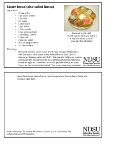


© Copyright 2026