
2006 Perimeter Road. Greenville, SC 29605
2006 Perimeter Road. Greenville, SC 29605
Toll Free: 800/435-9340 - Phone: 864/277-5870
Fax: 864/235-9661 - Website address: www.mightymole.com
Email address: [email protected]
Parts Manual
V100G Vacuum Machine
Part #E850100
(SERIAL #S1S092313128 - 1S1012314337)
© 2014 by McLaughlin Group, Inc.
040714
All rights reserved. No part of this manual may be reproduced in any form, or by any means
without prior written permission of McLaughlin Group, Inc.
Table of Contents
PARTS
SPOIL TANK AND FILTRATION
TANK AND DOOR .....................................................................................................................
ENGINE COMPARTMENT
ENGINE ......................................................................................................................................
BLOWER ....................................................................................................................................
WATER PUMP ...........................................................................................................................
REGULATOR .............................................................................................................................
WATER TANK AND ACCESSORIES
WATER TANKS - 50 GALLON SADDLE................................................................................
FILTRATION .............................................................................................................................
ELECTRICAL ..........................................................................................................................
TOOL RACK ..............................................................................................................................
TOOLS
REDUCTION TOOL .................................................................................................................
SUCTION TOOL .................................................................................................................
WASH WAND ............................................................................................................................
ROTARY LANCE ..............................................................................................................
ELECTRICAL SCHEMATICS
WIRING SCHEMATIC ....................................................................................................
4
6
8
12
16
18
20
22
24
26
28
30
32
35
MAINTENANCE MANUALS
ROOTS BLOWER .................................................................................................................... 37
HONDA ENGINE ..................................................................................................................... 65
WARRANTY
Tank and Door Assembly
1
V100G
2
3
4
21
20
5
18
19
17
6
16
15
7
14
13
8
9
10
11
12
110310-E
4
VACASSY030
Tank and Door Assembly
ITEM
1
2
3
21
QTY
1
1
1
1
1
1
1
1
4
4
4
8
24
8
8
9
1
1
1
1
2
1
2
1
2
2
1
1
1
1
2
1
1
1
PART NO.
X000109
8045655
8030531
8041291
8045578
8045550
8045549
8045579
8030904
U000560
8030851
U000420
U200060
U210060
U100060
8042812
8042381
8045248
8045517
8040255
8040374
8030916
8030174
8041855
J400060
W200120
8040306
8045612
8040413
8041764
8040159
8030393
8041485
8030392
DESCRIPTION
STRAIN RELIEF, 3/4”
TANK FLOAT SWITCH TUBE V100
HIGH LEVEL FLOAT SWITCH
RUBBER, BUSHING
MAIN PLATE WELDMENT
ACCESS PANEL GUARD 24HP V100G
BASE PANEL GUARD 24HP V100G
CONTROL BRACKET
ISOLATOR 840LB.
SCREW, HC 3/8”-16 X 3”
WASHER, SNUBBLING
SCREW, HC 3/8”-16 X 1”
WASHER, FLAT 3/8”
WASHER, LOCK 3/8”
NUT, HEX 3/8”-16
GROMMET 2”ID3”OD 1/4”WOG TRAILER SLOT
FUEL TANK 14GAL
STRAP, EYEBOLT 1” X 42.5” OAL
SKID WELDMENT V100G
CHUTE, VSK100 G/D
CHUTE HOLDER BRACE
4” GATE VALVE
WASHER, QUICKLOCK
DOOR HANDLE
1 7/8” KNOB
O-RING, #225
QUICK LOCK DOOR STRIKER
DOOR, V100G
DOOR HOLDER
SEAL, DOOR SQUARE V100
DOOR PIN ASSEMBLY
3” COUPLING PLUG
LANYARD CABLE
3” FEMALE COUPLING
*
*
*
*
*
*
1
1
2
2
1
1
8040239
X400040
U000020
U210020
X300217
X300230
BATTERY BOX w/ STRAP
BATTERY
SCREW, HC 1/4-20 X .75”
WASHER, LOCK 1/4”
CABLE BATTERY GND 1GA 40”
CABLE BATTRY HOT 1GA 55”
*
NOT SHOWN
4
5
6
7
8
9
10
11
12
13
14
15
16
17
18
19
20
110310-E
V100G
VACASSY030
5
V100G
Engine Honda GX660TAF
7
8
6
2
5
4
1
3
041414-E
6
VACASSY860
Engine Honda GX660TAF
ITEM
1
2
3
4
5
6
7
8
*
*
*
*
*
*
V100G
QTY
1
1
4
4
4
4
1
2
1
1
1
1
1
1
2
2
NUMBER
8046017
8046020
U000560
U100060
U210060
U200600
8046019
8046018
8040695
8040696
8042719
8046013
8046014
8046016
8046016-1
8046016-2
DESCRIPTION
ENGINE, HONDA 24HP
IGNITION KEY
SCREW, HC 3/8-16 X 3.00”
NUT, HEX 3/8-16
WASHER, LOCK 3/8”
WASHER, FLAT 3/8”
FILTER, AIR ELEMENT
SPARK PLUG
6.55”OD SD 3-GROOVE
BUSHING, 1 1/8” SD
FILTER, OIL
OIL COOLER
FUEL FILTER
MUFFLER
MUFFLER, EXHAUST GASKET R.H.
MUFFLER, EXHAUST NUT R.H.
1
1
1
1
1
2
8030689
T400041
8043846
8041517
T401067
8030436
MANUAL BOX
UNION, 3/8"MJ-M14 MALE W/SEAL
HOSE ASSY VAC 6-10 ST-90
HOSE VAC FUEL 5/16-36”
ELBOW,90 3/8"MP-3/8"M HOSEBARB
CLAMP,5/16" FUEL HOSE
* Not Shown
041414-E
VACASSY860
7
Blower Assembly
2
V100G
1
3
5
4
6
19
18
15
3
4
17
3
16
14
7
8
9
13
10
11
12
122810-E
8
VACASSY229
Blower Assembly
ITEM
1
2
3
4
5
6
7
8
9
10
11
12
13
14
15
16
17
18
19
*
122810-E
V100G
QTY
1
1
3
2
1
1
1
1
1
1
4
4
4
1
2
1
1
1
1
1
1
1
1
1
1
1
NUMBER
8030332
8044537
8030395
8045238
8040484
8040945
8040642
U410042
8041797
8041250
U000817
U210100
U200100
8045637
8042605
8045647
T320150
T402020
8030409
8040194
8044951
8043553
8045476
8045648
T400110
8041074
DESCRIPTION
SILENCER, 500CFM, COWL
3” RAIN CAP SILENT
3” U-BOLT CLAMP
3” HOSE X 3” MNPT ADAPTER
SHEAVE, 6.95”OD SDS 2-GROOVE (24 HP)
SHEAVE, 5.95”OD SDS 2-GROOVE (31HP)
BUSHING 7/8”SDS
KEY 3/16” X 3/16” X 2”
RETAINER
BLOWER (MODEL 47)
SCREW, HC 1/2”-13 X 1”
WASHER, LOCK 1/2”
WASHER, FLAT 1/2”
3” EXHAUST ELBOW TIGHT 90ID-OD WELDM’T
CLAMP T-BOLT 3” (350)
HOSE VAC KANAFLEX 3-35”
FITTING HOSE 4HO-4FJ 90
UNION, 4MJ-4MP
2” CLOSE NIPPLE
VALVE, 2” AIR RELIEF SET 10”LG
VACUUM RELIEF FILTER BUSHING
FILTER AIR 3” 245CFM
3” WYE W/2”NPT FLANGE
HOSE ASSY VAC 4-31 1/4” ST-90
UNION, 4FP-4MJ
VACUUM, GAUGE
2
2
8044517
8030379
BELT, BX 57 (24HP)
BELT, BX 51 (31HP)
VACASSY229
9
10
Assembly of URAI DSL Blowers with Splash Lubricated Drive End 3-5” Gear Diameter
URAI-DSL Splash Lubricated Blowers
4" Gear Diameter
Item #
Qty
1
2
1
1
Part #
8041250-1
8041250-2
3
1
8041250Ͳ3
4
2
8041250Ͳ4
7
1
8041250Ͳ7
11
1
8041250Ͳ11
12
1
8041250Ͳ12
13
1
8041250Ͳ13
14
3
8041250Ͳ14
15
1
8041250Ͳ15
16
4
8041250Ͳ16
17
2
8041250Ͳ17
19
1
8041250Ͳ19
21
3
8041250Ͳ21
23
6
8041250Ͳ23
25
1
8041250Ͳ25
26
*
8041250Ͳ26
27
4
8041250Ͳ27
31
4
8041250Ͳ31
32
6
8041250Ͳ32
33
1
8041250Ͳ33
34
2
8041250Ͳ34
35
2
8041250Ͳ35
39
4
8041250Ͳ39
40
2
8041250Ͳ40
42
2
8041250Ͳ42
48
4
8041250Ͳ48
50
1
8041250Ͳ50
52
2
8041250Ͳ52
53
2
8041250Ͳ53
*Quantities vary by blower.
Description
Headplate Gear End
Headplate Drive End
Gearbox
Timing Gears
Gasket, Gear Box, DE Cover
Cylinder
Impeller & Shaft Drive
Impeller & shaft Driven
Bearing, Ball
Bearing, Roller
Pin, Dowel
Gear Nut
Key
Plug, Pipe
Screw Hex
Breather (Plug Vent)
Screw, Hex
Seal, Lip Bearing
Screw, Hex, Nylock
Screw, Hex
Seal LipͲDrive
Clamp Plate
Foot
Washer Mounting
Screw Socket
Screw Hex
DE Oil Slinger Set Screw
Drive End Cover
Drive End Oil Slinger
Oil Sight Glass
11
Water Pump Assembly
100G
1
2
3
5
6
4
14
15
16
13
17
7
8
18
22
21
9
10
19
11
20
12
102810-E
12
VACASSY309
Water Pump Assembly
ITEM
1
2
3
4
5
6
7
8
9
10
11
12
13
14
15
16
17
18
19
20
21
22
102810-E
QTY
1
2
1
1
1
1
1
1
1
1
1
1
2
1
1
1
1
1
2
1
1
2
2
PART NO.
8040176
8040878
8040834
T401125
T400070
T400030
8040177
8030020
T401120
8041830
8030679
8045639
8030525
8030372
T400110
T400028
T402153
T400039
T320030
8045641
8045640
8030524
8040219
100G
DESCRIPTION
WATER PUMP SHEAVE/ CLUTCH
BELT, AX45
PUMP, WATER TX1510 S34
REDUCER, 3/8”MP-1/2”FJ
REDUCER, 8MP X 12MJ
REDUCER, 3/8”MP-1/2”MJ
UNLOADER VALVE
ROD, TENSIONER WELDMENT
ELBOW, 6MP-8MJ
HOSE, 3/8” X 30’ 4000PSI
FITTING, 3/8”FJ X 3/8”FP SWIVEL
HOSE VAC PUSH 12-12 3/4”
#12 PUSH LOCK
WATER PRESSURE GAUGE 1/4NPT
UNION, 1/4”FP-1/4”MJ
UNION, 3/8”MP-3/8”MJ
TEE, 6MJ-6MJ-6FJ
REDUCER, 6FJ-4MJ
FITTING, HOSE 4HO-4FJ
HOSE ASSY VAC 4-8” ST-ST
HOSE VAC PUSH 8-53”
#8 PUSH LOCK
WATER PUMP ADJ BLOCK
VACASSY309
13
Water Pump TX1510
Series “63”
ARTS LIST
TORQUE SPECS*
*Decrease torque by 20%
if threads are lubricated
Pos.
2
10
12
26
28
35
39
45
46
050409
14
Ft/lb
14.7
73.7
7.3
7.3
14.7
11.0
14.7
29.4
29.4
Nm
20
100
10
10
20
15
2
40
40
VACASSY327
Water Pump TX1510
KIT #
ITEM QTY. PART #
DESCRIPTION
1
2
3
4
5
6
7
8
9
10
11
12
13
14
15
16
17
18
19
20
21
22
23
24
25
26
27
28
29
30
31
32
33
34
35
36
37
38
39
40
41
42
43
44
45
46
47
48
49
50
8040834-KIT123
MANIFOLD, 15mm
8040834-KIT124
SCREW, M8 X 65
8040834-KIT159
LOCKWASHER, M8.4
8040834-KIT160
O-RING
8040834-KIT161
VALVE SEAT
8040834-KIT162
VALVE PLATE
8040834-KIT163
SPRING
8040834-KIT164
VALVE CAGE
8040834-KIT165
O-RING
8040834-KIT166
VALVE CAP
8040834-KIT167
VALVE ASSEMBLY
SCREW, M6 X 10
BEARING COVER
OIL LEVEL INDICATOR
O-RING
BALL BEARING
OIL SEAL
CRANKCASE
OIL DIP STICK
CRANKSHAFT 10mm
KEY
PLUNGER GUIDE
CONNECTING ROD
O-RING COVER
REAR CRANKCASE COVER
SCREW, M6 X 14
O-RING
PLUG, 1/4”G
CONNECTING ROD PIN
FLINGER WASHER
ANTI-EXTRUSION RING
O-RING
CERAMIC PLUNGER
BUSHING
NUT, M8
OIL SEAL
RAIL
LOCK WASHER, M8
SCREW, M8 X 16
SEAL RETN’R 15mm
O-RING
SEAL, LP, 15mm
INT. RING, 15mm
PACKING ASSY, 15mm
PLUG, 3/8”G
PLUG, 1/2”G
WASHER, M17.5
WASHER, M21.5
OIL LEVEL INDICATOR
O-RING
1
8
8
6
6
6
6
6
6
6
6
8
2
1
1
2
3
1
1
1
1
3
3
1
1
4
1
2
3
3
3
3
3
3
3
1
2
4
4
3
3
3
3
3
1
1
1
1
1
1
050409
8040834-1
8040834-2
8040834-3
8040834-4
8040834-5
8040834-6
8040834-7
8040834-8
8040834-9
8040834-10
8040834-11
8040834-12
8040834-13
8040834-14
8040834-15
8040834-16
8040834-17
8040834-18
8040834-19
8040834-20
8040834-21
8040834-22
8040834-23
8040834-24
8040834-25
8040834-26
8040834-27
8040834-28
8040834-29
8040834-30
8040834-31
8040834-32
8040834-33
8040834-34
8040834-35
8040834-36
8040834-37
8040834-38
8040834-39
8040834-40
8040834-41
8040834-42
8040834-43
8040834-44
8040834-45
8040834-46
8040834-47
8040834-48
8040834-49
8040834-50
ITEM #’S
INCL’D IN KIT
4,5,6,7,8,(11)
9,10
17
42,44
42,44
40
40
43
43
40,41,42,43,44
40,41,42,43,44
NO. OF ASSY
IN KIT
6
6
3
3
3
3
3
3
3
1
1
NO. OF CYL KIT
WILL SERVICE
3
3
3
3
3
3
3
3
3
1
1
VACASSY327
15
Unloader Valve PULSAR3KHP
INLET
BY-PASS
BY-PASS
DISCHARGE
INLET
050409
16
VACASSY328
Unloader Valve PULSAR3KHP
ITEM
1
2
3
4
5
6
7
8
10
11
12
13
14
15
16
17
20
21
22
23
24
27
28
29
30
31
32
050409
QTY
1
2
1
1
1
1
1
2
2
1
1
1
1
1
1
1
1
1
1
1
1
1
1
1
1
1
2
PART #
8040177-1
8040177-2
8040177-3
8040177-4
8040177-5
8040177-6
8040177-7
8040177-8
8040177-10
8040177-11
8040177-12
8040177-13
8040177-14
8040177-15
8040177-16
8040177-17
8040177-20
8040177-21
8040177-22
8040177-23
8040177-24
8040177-27
8040177-28
8040177-29
8040177-30
8040177-31
8040177-32
DESCRIPTION
INLET FITTING, 3/8 NPT-F
O-RING, .676ID X .070CS
BALL SPRING
SS BALL, 13/32
O-RING, .437ID X .070CS
SS SEAT, .551OD X .335ID
BRASS BODY, 3/8 NPT
PLUG, 3/8”NPT
BACKUP RING
O-RING, .424ID X .103CS
SS PISTON
O0RING, .299ID X .103CS
BACKUP RING
PISTON HOUSING
LOCKING PIN
BLUE SPRING
O-RING, .236ID X .118CS
CHECK VALVE
SS SPRING
O-RING, .739ID X .070CS
OUTLET FITTING, 3/8NPT-F
PLASTIC PLUG for KNOB
ZINC NUT, M8
INSERT M8
PLASTIC KNOB
WASHER, 9mm X 24mm
BRASS NUT, M8
VACASSY328
17
50Gallon
SINGLE
Water Tank Assembly
2
1
5
4
6
7
3
8
9
10
11
12
13
14
15
092110-E
18
VACASSY601
Water Tank Assembly
ITEM
1
14
15
QTY
1
1
2
1
1
1
1
1
2
1
1
1
1
1
1
1
1
1
1
1
1
1
1
1
*
NOT SHOWN
*
2
3
4
5
6
7
8
9
10
11
12
13
092110-E
PART NO.
8034151
8034151-1
8045244
8030020
T405065
8043806
8045093
T420120
8044266
8041525
T403017
T400101
T000185
T404060
8040186
8040186-1
8040186-2
8040186-3
8040186-4
8040186-5
8040186-6
8040186-7
T403080
8031252
50Gallon
SINGLE
DESCRIPTION
50 GALLON WATER TANK
TANK LID
STRAP, EYEBOLT 1” X 57”
BULHEAD ADAPTER 45DEG 1/2MJ
3/4” PLUG MB
SWITCH, WATER TANK BOTTOM SHORT
BULKHEAD 1 1/4” BOTTOM FEED
STREET ELBOW 90- 1 1/4”
FITTING, HOSE BARB 20HB-20MP
HOSE VAC CLEAR VINLY 1 1/4-12
REDUCER, 1 1/4”MP X 3/4”MJ
UNION, 3/4”FJ-3/4”MP
VALVE, BALL 3/4” FNPT BRASS
UNION, 16MP-12MP
STRAINER “Y” BANJO
END CAP
GASKET
STRAINER PLUG
FKM O-RING
STRAINER MESH SCREEN 80
Y-BODY
EPDM O-RING
REDUCER, 1”MP-3/4”FP
ELBOW, 12MP-12MJ 45
VACASSY601
19
Filtration
V100G
10
9
8
7
3
2
4
5
1
6
11
12
13
14
15
5
083010-E
20
VACASSY350
Filtration
ITEM
1
2
3
4
5
6
7
8
9
10
11
12
13
14
15
QTY
1
1
1
1
2
1
1
2
1
1
1
4
8
4
1
2
1
2
1
2
1
4
4
4
1
1
1
083010-E
PART #
8041218
8041357
8041534
U000560
U200600
U210061
U130080
8041232
U200100
8031178
8040228
U000420
U200600
U210061
8045297
8042605
8045649
8042605
8045650
8042605
8040308
U000420
U200600
U210060
8041273
8041444
8041197
V100G
DESCRIPTION
KNOB, AIR FILTER
DOOR SEAL AIR FILTER 575
575 AIR FILTER DOOR WITH TAB
SCREW, HC 3/8”-16 X 3.00
WASHER, FLAT 3/8”
NUT, HEX NY 3/8-16
NUT, WING 1/2-13
WASHER, RUBBER BACKED 1/2”
WASHER, FLAT 1/2”
FILTER, ELEMENT 575
AIR FILTER 575
SCREW, HC 3/8-16 X 1.00
WASHER, FLAT 3/8”
NUT, HEX NY 3/8-16
HOSE VAC KANAFLEX 3-34”
CLAMP, T-BOLT 3” (350)
HOSE VAC KANAFLEX 3-28”
CLAMP, T-BOLT 3” (350)
HOSE VAC KANAFLEX 3-60 3/4”
CLAMP, T-BOLT 3” (350)
CYCLONE 100, WET
SCREW, HC 3/8-16 X 1.00
WASHER, FLAT 3/8”
WASHER LOCK
100 GALLON CYCLONE DOOR WELDMENT
DOOR SEAL CYCLONE 575/1025
KNOB, CYCLONE
VACASSY350
21
Control Panel G-Series
100G
SPOIL TANK
FULL LIGHT
SPOIL TANK
FULL / OVERRIDE LIGHT
WATER
ON / OFF
SPOIL TANK
FULL / OVERRIDE
ANTIFREEZE
2
3
1
4
6
5
10
4
6
5
12
7
8
11
9
041713-E
22
VACASSY01507
Control Panel G-Series
ITEM
1
2
3
4
5
6
7
8
9
10
11
12
QTY
1
4
1
8
8
8
1
1
1
1
1
1
*
NOT SHOWN
041713-E
PART NO.
X000109
U120100
8048638
U200020
U000040
U210020
8048634
8048633
J200636
X000260
X000270
X000274
100G
DESCRIPTION
STRAIN RELIEF, 3/4”
NUT, LOCK 1/4”-20
CONTROL BOX (SMALL)
WASHER, FLAT 1/4”
SCREW, HC 1/4”-20 X .75”
WASHER, LOCK 1/4”
COVER PLATE GASKET
COVER PLATE
DECAL, CONTROL PANEL
LIGHT, LED DUAL PANEL
SWITCH, ROCKER SPST ON-OFF
SWITCH, ROCKER DPST (ON) OFF (ON)
VACASSY01507
23
STD
Tool Rack Assembly
I-BEAM TRAILER
5
1
3
2
6
SKID UNIT
7
4
8
090909-E
24
VACASSY757
Tool Rack Assembly
ITEM
1
2
3
4
5
6
7
8
090909-E
QTY
1
1
1
1
1
1
1
1
1
4
4
16
8
1
3
3
6
1
4
8
4
1
4
8
4
2
4
2
PART NO.
8040985
8045610
8040884
R700175
8041259
8041485
8041244
8045609
8044818
U000020
U000180
U200040
U210041
8044817
U000420
U120110
U200600
8041780
U000040
U200020
U120100
8043601
U000420
U200060
U120110
U000040
U200020
U120100
STD
DESCRIPTION
TOOL RACK WELDMENT
TOOL RACK 3” TOP INSERT
TOOL RACK CLOSURE
R CLIP 7/8”
STRAP, 10”
LANYARD CABLE
CLEVIS PIN 1/2” DIA. 3/4”
TOOL RACK BOTTOM INSERT
ANTIFREEZE BRACKET (I-BEAM TRAILER)
SCREW, HC 5/16”-18 X 1.00”
SCREW, HC 5/16”-18 X .750”
WASHER, FLAT 5/16”
NUT, LOCK NY 5/16”
TOOL RACK BRACKET (I-BEAM TRAILER)
SCREW, HC .375”-16 X 1.00”
NUT, LOCK .375”-16
WASHER, FLAT .375”
ENCLOSURE STIFFENER BRACE (SKID UNITS)
SCREW, HC 1/4”-20 X .750”
WASHER, FLAT .250”
NUT, LOCK .250”
TOOL RACK BRACKET (SKID UNITS)
SCREW, HC .375”-16 X 1.00”
WASHER, FLAT .375”
NUT, LOCK .375-16
SCREW, HC 1/4”-20 X .750”
WASHER, FLAT .250”
NUT, LOCK .250”
VACASSY757
25
Tools (Option)
Reduction Tool
100G/LEG
14
1
8
16
9
2
3
13
12
5
6
15
4
9
8
10
012213-E
26
11
VACASSY01700
Tools(Option)
ITEM
1
2
3
4
5
6
7
8
9
10
11
12
13
14
15
16
*
QTY
1
1
1
1
1
2
1
2
2
1
1
1
2
1
1
1
2
PART NO.
8043113
8042862
8048567
8042811
T400023
8030486
T320030
8031278
8042605
8042855
8030627
8043764
T400020
T422010
8030391
T401065
T401100
8030370
Reduction Tool
100G/LEG
DESCRIPTION
TOOL VAC REDUCTION 100G/LEG COMPLETE
TOOL VAC HEAD ASSY 3”
STRAIGHT SPRAY GUN
TOOL VAC REDUCTION PVC 3" X 48"
UNION 6MP 4FP
WATER QD 1/4 MNPT SS
FITTING, HOSE 4HO 4FJ
HOSE ASSEMBLY REDUCTION TOOL
CLAMP HOSE T BOLT 350
CLAMP HOSE T BOLT 375
TOOL VAC REDUCTION LOWER ASSY
VAC WATER SUPPLY TUBE CHROME 1/4NPT
UNION 1/4" MP-1/4" MJ STRAIGHT
COUPLING,PIPE 1/4"FP
BANJO 3" MALE 3" FNPT
ELBOW, 3/8 MP - 3/8 FP
ELBOW 4MP 4MJ 90
REDUCTION TOOL NOZZLE #2 0DEG
* NOT SHOWN
012213-E
VACASSY01700
27
Tools
3” Suction Tool
1
4
3
2
111210-E
28
VACASSY712
Tools
ITEM
1
2
3
4
111210-E
QTY
1
1
1
1
1
3” Suction Tool
NUMBER
8030215
8030317
8030313
8030356
8030391
DESCRIPTION
TOOL VAC SUCTION 3" COMPLETE
TOOL VAC HANDLE ASSEMBLY 3"
PVC VACUUM TUBE 3"
CLAMP,4"PUNCHLOCK P16-S
COUPLING, 3" BANJO
VACASSY712
29
Tools
Wash Wand
1
2
3
031814-E
30
VACASSY711
Tools
Item
1
2
3
031814-E
Qty
1
1
1
1
Wash Wand
Number
8030348
8030928
8030847
8031303
Description
TOOL VAC SPRAY WAND COMPLETE
TRIGGER ASSEMBLY
WAND
NOZZLE,#10 40 DEGREE FOR WAND
VACASSY711
31
Tools
Rotary Lance
100G & LEG
3
2
1
4
5
120712-E
32
VACASSY719
Tools
ITEM
*
1
2
3
4
5
QTY
1
1
1
1
1
120712-E
PART NO.
8042082
8048567
T400023
8030486
8043765
8048739
Rotary Lance
100G & LEG
DESCRIPTION
TOOL VAC ROTARY LANCE COMPLETE
STRAIGHT SPRAY GUN
UNION 6MP-4FP
WATER QD 1/4MNPT SS
TUBE,CHROME 1/4NPT ENDS 60"
NOZZLE ROTATING 055
VACASSY719
33
PAGE LEFT BLANK
34
V100G ELECTRICAL SCHEMATIC
YELLOW/BLACK WIRE
20 AMP
FUSE
SPARK
PLUG
WIRE
HONDA ENGINE
RED/BLACK WIRE
3
HOUR
METER
87A
87
30
86
2
85
87A
1
SOLENOID
LP
LP
SP
SP
30
87
85
86
TANK FULL
OVERRIDE
TOGGLE
87A
87
30
86
85
OVERRIDE
LIGHT
TANK
FULL
LIGHT
LOW WATER
SHUT OFF
SWITCH
WATER
PUMP
CLUTCH
IN-TANK
FLOAT
SWITCH
35
RELAY SOCKET WIRE CODES
RELAY CONNECTOR
WIRE COLOR
30
BLACK
85
WHITE
86
RED
87A
BLUE
87
GREEN
WIRING SCHEMATIC
WATER
PUMP
CLUTCH
TOGGLE
PAGE LEFT BLANK
36
INSTALLATION OPERATION MAINTENANCE
BLOWERS EXHAUSTERS COMPRESSORS
ROOTS
™
US $3.00, Canada $4.50
Universal RAI®, URAI-DSL, URAI-G and Metric Series
Contents
Information Summary . . . . . . . . . . . . . . . . . . . . . . . . . . . . 1
Inspection & Maintenance. . . . . . . . . . . . . . . . . . . . . . . . 11
Safety Precautions. . . . . . . . . . . . . . . . . . . . . . . . . . . . . . . 3
Figures. . . . . . . . . . . . . . . . . . . . . . . . . . . . . . . . . . . 12-15
Operating Limitations. . . . . . . . . . . . . . . . . . . . . . . . . . . . . 3
Tables. . . . . . . . . . . . . . . . . . . . . . . . . . . . . . . . . . . . . 15-16
Installation. . . . . . . . . . . . . . . . . . . . . . . . . . . . . . . . . . . . 4
Assembly Drawings. . . . . . . . . . . . . . . . . . . . . . . . . . .17-22
Lubrication. . . . . . . . . . . . . . . . . . . . . . . . . . . . . . . . . . . . 8
Parts List. . . . . . . . . . . . . . . . . . . . . . . . . . . . . . . . . . . 23-24
Operation. . . . . . . . . . . . . . . . . . . . . . . . . . . . . . . . . . . . . 9
Basic Connection & Drive Shaft Information. . . . . . . . . 25-27
Troubleshooting. . . . . . . . . . . . . . . . . . . . . . . . . . . . . . . . . 10
Do These Things To Get The Most From Your ROOTS® blower
❏
Read starting check points under OPERATION. Run
equipment briefly to check for installation errors and
make corrections. Follow with a trial run under normal
operating conditions.
❏
In event of trouble during installation or operation, do
not attempt repairs of ROOTS furnished equipment.
Notify ROOTS, giving all nameplate information plus an
outline of operating conditions and a description of the
trouble. Unauthorized attempts at equipment repair may
void ROOTS warranty.
❏
Units out of warranty may be repaired or adjusted by the
owner. Good inspection and maintenance practices
should reduce the need for repairs.
❏
Check shipment for damage. If found, file claim with
carrier and notify ROOTS.
❏
Unpack shipment carefully, and check contents against
Packing List. Notify ROOTS if a shortage appears.
❏
Store in a clean, dry location until ready for installation.
Lift by methods discussed under INSTALLATION to
avoid straining or distorting the equipment. Keep covers
on all openings. Protect against weather and corrosion if
outdoor storage is necessary.
❏
Read OPERATING LIMITATIONS and INSTALLATION sections in this manual and plan the complete installation.
❏
Provide for adequate safeguards against accidents to
persons working on or near the equipment during both
installation and operation. See SAFETY PRECAUTIONS.
NOTE: Information in this manual is correct as of the date of
publication. ROOTS reserves the right to make design or
material changes without notice, and without obligation to
make similar changes on equipment of prior manufacture.
❏
Install all equipment correctly. Foundation design must
be adequate and piping carefully done. Use recommended accessories for operating protection.
For your nearest ROOTS Office, dial our Customer Service
Hot Line toll free; 1 877 363 ROOT(S) (7668) or direct 281966-4700.
❏
Make sure both driving and driven equipment is correctly lubricated before start-up. See LUBRICATION.
ISRB-2002 rev.0705
(formerly IOM-180-205)
37
ROOTS® products are sold subject to the
current General Terms of Sale, GTS-5001
and Warranty Policy WP-5020. Copies are
available upon request.
Contact your local ROOTS Office
or ROOTS Customer Service
Hot Line 1-877-363-ROOT(S) (7668) or
direct 281-966-4700.
38
Safety Precautions
It is important that all personnel observe safety precautions
to minimize the chances of injury. Among many considerations, the following should be particularly noted:
•
•
Blower casing and associated piping or accessories may
become hot enough to cause major skin burns on contact.
Internal and external rotating parts of the blower and
driving equipment can produce serious physical injuries.
Do not reach into any opening in the blower while it is
operating, or while subject to accidental starting. Protect
external moving parts with adequate guards.
•
Disconnect power before doing any work, and avoid
bypassing or rendering inoperative any safety or protective devices.
•
If blower is operated with piping disconnected, place a
strong coarse screen over the inlet and avoid standing in
the discharge air stream. CAUTION: Never cover the
blower inlet with your hand or other part of body.
•
Stay clear of the blast from pressure relief valves and the
suction area of vacuum relief valves.
•
Use proper care and good procedures in handling, lifting,
installing, operating and maintaining the equipment.
•
Casing pressure must not exceed 25 PSI (1725 mbar)
gauge. Do not pressurize vented cavities from an external
source, nor restrict the vents without first consulting
ROOTS.
•
Do not use air blowers on explosive or hazardous gases.
•
Other potential hazards to safety may also be associated
with operation of this equipment. All personnel working
in or passing through the area should be trained to exercise adequate general safety precautions.
•
Measured temperature rise must not exceed listed values when the inlet is at ambient temperature. Ambient
is considered as the general temperature of the space
around the unit. This is not outdoor temperature unless
the unit is installed outdoors.
•
If inlet temperature is higher than ambient, the listed
allowable temperature rise values must be reduced by
2/3 of the difference between the actual measured inlet
temperature and the ambient temperature.
•
The average of the inlet and discharge temperature must
not exceed 250°F. (121°C).
•
The ambient temperature of the space the blower/motor
is installed in should not be highter than 120°F (48.8°C).
Operating Limitations
A ROOTS blower or exhauster must be operated within certain approved limiting conditions to enable continued satisfactory performance. Warranty is contingent on such operation.
Maximum limits for pressure, temperature and speed are
specified in TABLE 1 for various models & sizes of blowers &
exhausters. These limits apply to all units of normal construction, when operated under standard atmospheric conditions. Be sure to arrange connections or taps for instruments, thermometers and pressure or vacuum gauges at or
near the inlet and discharge connections of the unit. These,
along with a tachometer, will enable periodic checks of operating conditions.
PRESSURE – The pressure rise, between inlet and discharge,
must not exceed the figure listed for the specific unit frame
size concerned. Also, in any system where the unit inlet is at
a positive pressure above atmosphere a maximum case rating of 25 PSI gauge (1725 mbar) should not be exceeded
without first consulting the ROOTS. Never should the maximum allowable differential pressure be exceeded.
On vacuum service, with the discharge to atmospheric pressure, the inlet suction or vacuum must not be greater than
values listed for the specific frame size.
TEMPERATURE – Blower & exhauster frame sizes are
approved only for installations where the following temperature limitations can be maintained in service:
SPEED – These blowers & exhausters may be operated at
speeds up to the maximum listed for the various frame sizes.
They may be direct coupled to suitable constant speed drivers if pressure/temperature conditions are also within limits.
At low speeds, excessive temperature rise may be a limiting
factor.
Special Note: The listed maximum allowable temperature
rise for any particular blower & exhauster may occur well
before its maximum pressure or vacuum rating is reached.
This may occur at high altitude, low vacuum or at very low
speed. The units’ operating limit is always determined by the
maximum rating reached first. It can be any one of the three:
Pressure, Temperature or Speed.
For your nearest ROOTS office contact information, please consult the last page of this document.
3
39
Installation
ROOTS blowers & exhausters are treated after factory
assembly to protect against normal atmospheric corrosion.
The maximum period of internal protection is considered to
be one year under average conditions, if shipping plugs &
seals are not removed. Protection against chemical or salt
water atmosphere is not provided. Avoid opening the unit
until ready to start installation, as corrosion protection will
be quickly lost due to evaporation.
If there is to be an extended period between installation and
start up, the following steps should be taken to ensure corrosion protection.
❏
Coat internals of cylinder, gearbox and drive end bearing
reservoir with Nox-Rust VCI-10 or equivalent. Repeat
once a year or as conditions may require. Nox-Rust
VCI-10 is petroleum soluble and does not have to be
removed before lubricating. It may be obtained from
Daubert Chemical Co., 2000 Spring Rd., Oak Brook, Ill.
60521.
❏
Paint shaft extension, inlet and discharge flanges, and all
other exposed surfaces with Nox-Rust X-110 or equivalent.
❏
Seal inlet, discharge, and vent openings. It is not recommended that the unit be set in place, piped to the
system, and allowed to remain idle for extended periods.
If any part is left open to the atmosphere, the Nox-Rust
VCI-10 vapor will escape and lose its effectiveness.
❏
Protect units from excessive vibration during storage.
❏
Rotate shaft three or four revolutions every two weeks.
❏
Prior to start up, remove flange covers on both inlet and
discharge and inspect internals to insure absence of
rust. Check all internal clearances. Also, at this time,
remove gearbox and drive end bearing cover and inspect
gear teeth and bearings for rust.
Because of the completely enclosed unit design, location of
the installation is generally not a critical matter. A clean, dry
and protected indoor location is preferred. However, an outdoor location will normally give satisfactory service.
Important requirements are that the correct grade of lubricating oil be provided for expected operating temperatures, and
that the unit be located so that routine checking and servicing can be performed conveniently. Proper care in locating
driver and accessory equipment must also be considered.
Supervision of the installation by a ROOTS Service Engineer
is not usually required for these units. Workmen with experience in installing light to medium weight machinery should
be able to produce satisfactory results. Handling of the
equipment needs to be accomplished with care, and in compliance with safe practices. Unit mounting must be solid,
without strain or twist, and air piping must be clean, accurately aligned and properly connected.
Bare-shaft Units: Two methods are used to handle a unit
without base. One is to use lifting lugs bolted into the top of
the unit headplates. Test them first for tightness and frac-
40
tures by tapping with a hammer. In lifting, keep the direction
of cable pull on these bolts as nearly vertical as possible. If
lifting lugs are not available, lifting slings may be passed
under the cylinder adjacent to the headplates. Either method
prevents strain on the extended drive shaft.
Packaged Units: When the unit is furnished mounted on a
baseplate, with or without a driver, use of lifting slings passing under the base flanges is required. Arrange these slings
so that no strains are placed on the unit casing or mounting
feet, or on any mounted accessory equipment. DO NOT use
the lifting lugs in the top of the unit headplates.
Before starting the installation, remove plugs, covers or seals
from unit inlet and discharge connections and inspect the
interior completely for foreign material. If cleaning is
required, finish by washing the cylinder, headplates and
impeller thoroughly with a petroleum solvent. Turn the drive
shaft by hand to make sure that the impellers turn freely at
all points. Anti-rust compound on the connection flanges
and drive shaft extension may also be removed at this time
with the same solvent. Cover the flanges until ready to connect piping.
Mounting
Care will pay dividends when arranging the unit mounting.
This is especially true when the unit is a “bare-shaft” unit
furnished without a baseplate. The convenient procedure
may be to mount such a unit directly on a floor or small concrete pad, but this generally produces the least satisfactory
results. It definitely causes the most problems in leveling
and alignment and may result in a “Soft Foot” condition.
Correct soft foot before operation to avoid unnecessary loading on the casing and bearings. Direct use of building structural framing members is not recommended.
For blowers without a base, it is recommended that a well
anchored and carefully leveled steel or cast iron mounting
plate be provided. The plate should be at least 1 inch (25
mm) thick, with its top surface machined flat, and large
enough to provide leveling areas at one side and one end
after the unit is mounted. It should have properly sized
studs or tapped holes located to match the unit foot drilling.
Proper use of a high quality machinist’s level is necessary for
adequate installation.
With the mounting plate in place and leveled, set the unit on
it without bolting and check for rocking. If it is not solid,
determine the total thickness of shims required under one
foot to stop rocking. Place half of this under each of the
diagonally-opposite short feet, and tighten the mounting
studs or screws. Rotate the drive shaft to make sure the
impellers turn freely. If the unit is to be direct coupled to a
driving motor, consider the height of the motor shaft and the
necessity for it to be aligned very accurately with the unit
shaft. Best unit arrangement is directly bolted to the mounting plate while the driver is on shims of at least 1/8 inch
(3mm) thickness. This allows adjustment of motor position
in final shaft alignment by varying the shim thickness.
Aligning
When unit and driver are factory mounted on a common
baseplate, the assembly will have been properly aligned and
is to be treated as a unit for leveling purposes. Satisfactory
installation can be obtained by setting the baseplate on a concrete slab that is rigid and free of vibration, and leveling the
top of the base carefully in two directions so that it is free of
twist. The slab must be provided with suitable anchor bolts.
The use of grouting under and partly inside the leveled and
shimmed base is recommended.
It is possible for a base-mounted assembly to become twisted during shipment, thus disturbing the original alignment.
For this reason, make the following checks after the base has
been leveled and bolted down. Disconnect the drive and
rotate the unit shaft by hand. It should turn freely at all
points. Loosen the unit foot hold-down screws and determine whether all feet are evenly in contact with the base. If
not, insert shims as required and again check for free
impeller rotation. Finally, if unit is direct coupled to the driver, check shaft and coupling alignment carefully and make
any necessary corrections.
In planning the installation, and before setting the unit, consider how piping arrangements are dictated by the unit
design and assembly. Drive shaft rotation must be established accordingly and is indicated by an arrow near the
shaft.
Typical arrangement on vertical units has the drive shaft at
the top with counterclockwise rotation and discharge to the
left. Horizontal units are typically arranged with the drive
shaft at the left with counterclockwise rotation and discharge
down. See Figure 4 for other various unit arrangements and
possible conversions.
When a unit is DIRECT COUPLED to its driver, the driver RPM
must be selected or governed so as not to exceed the maximum speed rating of the unit. Refer to Table 1 for allowable
speeds of various unit sizes.
A flexible type coupling should always be used to connect the
driver and unit shafts.
When direct coupling a motor or engine to a blower you must
insure there is sufficient gap between the coupling halves and
the element to prevent thrust loading the blower bearings.
When a motor, engine or blower is operated the shafts may
expand axially. If the coupling is installed in such a manner
that there is not enough room for expansion the blower shaft
can be forced back into the blower and cause the impeller to
contact the gear end headplate resulting in damage to the
blower. The two shafts must be in as near perfect alignment
in all directions as possible, and the gap must be established
with the motor armature on its electrical center if end-play
exists. Coupling manufacturer’s recommendations for maximum misalignment, although acceptable for the coupling, are
normally too large to achieve smooth operation and maximum life of the blower.
The following requirements of a good installation are recommended. When selecting a coupling to be fitted to the blower
shaft ROOTS recommends a taper lock style coupling to
insure proper contact with the blower shaft. If the coupling
must have a straight bore the coupling halves must be fitted
to the two shafts with a line to line thru .001” interference fit.
Coupling halves must be warmed up per coupling manufacturer’s recommendations. Maximum deviation in offset alignment of the shafts should not exceed .005” (.13 mm) total
indicator reading, taken on the two coupling hubs. Maximum
deviation from parallel of the inside coupling faces should not
exceed .001” (.03 mm) when checked at six points around
the coupling.
When a unit is BELT DRIVEN, the proper selection of sheave
diameters will result in the required unit speed. When selecting a sheave to be fitted to the blower shaft ROOTS recommends a taper lock style sheave to insure proper contact with
the blower shaft. This flexibility can lead to operating temperature problems caused by unit speed being too low. Make
sure the drive speed selected is within the allowable range for
the specific unit size, as specified under Table 1.
Belt drive arrangements usually employ two or more V-belts
running in grooved sheaves. Installation of the driver is less
critical than for direct coupling, but its shaft must be level
and parallel with the unit shaft. The driver should be mounted on the inlet side of a vertical unit (horizontal piping) and
on the side nearest to the shaft on a horizontal unit. SEE
PAGE 6 - Acceptable Blower Drive Arrangement Options.
The driver must also be mounted on an adjustable base to
permit installing, adjusting and removing the V-belts. To
position the driver correctly, both sheaves need to be mounted on their shafts and the nominal shaft center distance
known for the belt lengths to be used.
CAUTION: Drive couplings and sheaves (pulleys) should have
an interference fit to the shaft of the blower (set screw types
of attachment generally do not provide reliable service.) It is
recommended that the drive coupling or sheave used have a
taper lock style bushing which is properly sized to provide the
correct interference fit required. Drive couplings, that require
heating to fit on the blower shaft, should be installed per coupling manufacturer recommendations. A drive coupling or
sheave should not be forced on to the shaft of the blower as
this could affect internal clearances resulting in damage to
the blower.
Engine drive applications often require special consideration
to drive coupling selection to avoid harmful torsional vibrations. These vibrations may lead to blower damage if not
dampened adequately. It is often necessary to install a flywheel and/or a torsionally soft elastic element coupling
based on the engine manufacturer recommendations.
The driver sheave should also be mounted as close to its
bearing as possible, and again should fit the shaft correctly.
Position the driver on its adjustable base so that 2/3 of the
total movement is available in the direction away from the
unit, and mount the assembly so that the face of the sheave
is accurately in line with the unit sheave. This position minimizes belt wear, and allows sufficient adjustment for both
installing and tightening the belts. After belts are installed,
adjust their tension in accordance with the manufacturer’s
instructions. However, only enough tension should be
applied to prevent slippage when the unit is operating under
load. Excessive tightening can lead to early bearing concerns
or shaft breakage.
Before operating the drive under power to check initial belt
tension, first remove covers from the unit connections. Make
sure the interior is still clean, then rotate the shaft by hand.
Place a coarse screen over the inlet connection to prevent
anything being drawn into the unit while it is operating, and
avoid standing in line with the discharge opening. Put oil in
the sumps per instructions under LUBRICATION.
Piping
Before connecting piping, remove any remaining anti-rust
compound from unit connections. Clean pipe should be no
For your nearest ROOTS office contact information, please consult the last page of this document.
5
41
Acceptable Blower Drive Arrangement Options
ACCEPTABLE
UNACCEPTABLE
Top Shaft
DISCHARGE
Top Shaft
INLET
DISCHARGE
Motor On Inlet Side of Blower (Top Shaft)
DISCHARGE
Motor On Discharge Side of Blower (Top Shaft)
INLET
DISCHARGE
Bottom Shaft
INLET
Bottom Shaft
smaller than unit connections. In addition, make sure it is
free of scale, cuttings, weld beads, or foreign material of any
kind. To further guard against damage to the unit, especially
when an inlet filter is not used, install a substantial screen of
16 mesh backed with hardware cloth at or near the inlet connections. Make provisions to clean this screen of collected
debris after a few hours of operation. It should be removed
when its usefulness has ended, as the wire will eventually
deteriorate and small pieces going into the unit may cause
serious damage.
Pipe flanges or male threads must meet the unit connections
accurately and squarely. DO NOT attempt to correct misalignment by springing or cramping the pipe. In most cases
this will distort the unit casing and cause impeller rubbing.
In severe cases it can prevent operation or result in a broken
drive shaft. For similar reasons, piping should be supported
near the unit to eliminate dead weight strains. Also, if pipe
expansion is likely to occur from temperature change, installation of flexible connectors or expansion joints is advisable.
Figure 3 represents an installation with all accessory items
that might be required under various operating conditions.
Inlet piping should be completely free of valves or other
restrictions. When a shut-off valve can not be avoided, make
sure a full size vacuum relief is installed nearest the unit inlet.
This will protect against unit overload caused by accidental
closing of the shut-off valve.
Need for an inlet silencer will depend on unit speed and pressure, as well as sound-level requirements in the general surroundings. An inlet filter is recommended, especially in dusty
Drive Shaft
INLET
Motor On Discharge Side of Blower (Bottom Shaft)
DISCHARGE
Motor On Drive Shaft
Side of Blower
Driven Shaft
DISCHARGE
Drive Shaft
INLET
Motor On Inlet Side of Blower (Bottom Shaft)
42
INLET
Driven Shaft
Motor On Driven Shaft
Side of Blower
or sandy locations. A discharge silencer is also normally
suggested, even though Whispair units operate at generally
lower noise levels than conventional rotary blowers. Specific
recommendations on silencing can be obtained from your
local ROOTS distributor.
Discharge piping requires a pressure relief valve, and should
include a manual unloading valve to permit starting the unit
under no-load conditions. Reliable pressure/vacuum gauges
and good thermometers at both inlet and discharge are recommended to allow making the important checks on unit
operating conditions. The back-pressure regulator shown in
Figure 3 is useful mainly when volume demands vary while
the unit operates at constant output. If demand is constant,
but somewhat lower than the unit output, excess may be
blown off through the manual unloading valve.
In multiple unit installations where two or more units operate
with a common header, use of check valves is mandatory.
These should be of a direct acting or free swinging type, with
one valve located in each line between the unit and header.
Properly installed, they will protect against damage from
reverse rotation caused by air and material back-flow through
an idle unit.
After piping is completed, and before applying power, rotate
the drive shaft by hand again. If it does not move with uniform freedom, look for uneven mounting, piping strain,
excessive belt tension or coupling misalignment.
DO NOT operate the unit at this time unless it has been lubricated per instructions.
Technical Supplement for URAI® Gas Blowers
Technical Supplement for 32, 33, 36, 42, 45, 47, 53, 56, 59,
65, 68, 615 Universal RAI-G blowers
ROOTS Universal RAI-G rotary positive gas blowers are a
design extension of the basic Universal RAI blower model.
URAI-G blower uses (4) mechanical seals in place of the
standard inboard lip seals to minimize gas leakage into the
atmosphere. The seal vent chambers are plugged. These
units are intended for gases which are compatible with cast
iron case material, steel shafts, 300/400 series stainless steel
and carbon seal components, viton o-rings and the oil/grease
lubricants. If there are any questions regarding application or
operation of this gas blower, please contact factory.
Precaution: URAI-G blowers: Care must be used when
opening the head plate seal vent chamber plugs (43) as
some gas will escape–if it is a pressure system, or the
atmospheric air will leak in-if the system is under vacuum.
There is a possibility of some gas leakage through the
mechanical seals. This leakage on the gear end will escape
through the gear box vent, and on the drive end, through the
grease release fittings. If the gas leakage is undesirable,
each seal chamber must be purged with an inert gas
through one purge gas hole (43) per seal . There are two
plugged purge gas holes(1/8 NPT) provided per seal. The
purge gas pressure must be maintained one psi above the
discharge gas pressure. Also, there exists a possibility of
gear end oil and drive end grease leakage into the gas
stream.
The lubricants selected must be compatible with the gas.
URAI GAS Blower Oil and Grease Specifications
The specified oil should be ROOTS synthetic P/N 813-106- of
the proper viscosity.
When servicing drive end bearings of a Gas blower, use the
specified NLGI #2 premium grade aluminum complex*
grease, ROOTS P/N T20019001, with 300°F (149°C) service
temperature and moisture resistance and good mechanical
stability.
*ROOTS Synthetic Oil & Grease is superior in performance to
petroleum based products. It has high oxidation stability, excellent corrosion
protection, extremely high film strength and low coefficient of friction. Typical
oil change intervals are increased 2-3 times over petroleum based lubricants.
Also, ROOTS Synthetic Oil is 100% compatible with petroleum based oils.
Simply drain the oil in the blower and refill the reservoirs with ROOTS Synthetic
Oil to maintain optimum performance of your ROOTS blower.
For your nearest ROOTS office contact information, please consult the last page of this document.
7
43
Lubrication
For Units with a Grease Lubricated Drive End
and is drained downward.
A simple but very effective lubrication system is employed on
the drive shaft end bearings. Hydraulic pressure relief fittings
are provided to vent any excess grease, preventing pressure
build-up on the seals. A restriction plug and metering orifice
prevent loss of lubricant from initial surges in lubricant pressure but permit venting excess lubricant under steadily rising
pressures.
Oil sumps on each end of the blower are filled by removing
top vent plugs, Item (25), and filling until oil reaches the middle of the oil level sight gauge, Item (45 or 53), or the overflow plug (see pages 14 and 15).
When servicing drive end bearings of Non Gas blower, use
the specified NLGI #2 premium grade microgel grease with
250°F (121°C) service temperature and moisture resistance
and good mechanical stability. ROOTS specifies Shell Darina
EP NLGI Grade 2. Product Code 71522.
URAI GAS Blower Oil and Grease Specifications
The specified oil should be ROOTS synthetic P/N 813-106- of
the proper viscosity.
When servicing drive end bearings of a Gas blower, use the
specified NLGI #2 premium grade aluminum complex*
grease, ROOTS P/N T20019001, with 300°F (149°C) service
temperature and moisture resistance and good mechanical
stability.
NOTE: Lithium based greases are not compatible with the
ROOTS Synthetic grease used when assembling a Gas blower or the non-soap base grease used when assembling a
standard URAI blower. Lithium based grease is not
approved for any ROOTS blowers.
Using a pressure gun, slowly force new lubricant into each
drive end bearing housing until traces of clean grease comes
out of the relief fitting. The use of an electric or pneumatic
grease gun could force the grease in too rapidly and thus
invert the seals and should not be used.
After a long shutdown, it is recommended that the grease fittings be removed, the old grease flushed out with kerosene
or #10 lubricating oil, drained thoroughly, and bearings
refilled with new grease. Be sure grease relief fittings are
reinstalled. Grease should be added using a hand operated
grease gun to the drive end bearings at varying time intervals
depending on duty cycle and RPM. Table 4 has been prepared as a general greasing schedule guide based on average
operating conditions. More frequent intervals may be necessary depending on the grease operating temperature and
unusual circumstances.
For Units with Splash Lubrication on Both Ends
Bearings and oil seals are lubricated by the action of the timing gears or oil slingers which dip into the main oil sumps
causing oil to splash directly on gears and into bearings and
seals. A drain port is provided below each bearing to prevent
an excessive amount of oil in the bearings. Seals located
inboard of the bearings in each headplate effectively retain oil
within the sumps. Any small leakage that may occur should
the seals wear passes into a cavity in each vented headplate
44
Initial filling of the sumps should be accomplished with the
blower not operating, in order to obtain the correct oil level.
Approximate oil quantities required for blowers of the various
models and configurations are listed in Table 3. Use a good
grade of industrial type non-detergent, rust inhibiting, antifoaming oil and of correct viscosity per Table 2. *ROOTS synthetic oil (ROOTS P/N 813-106-) is highly recommended.
ROOTS does not recommend automotive type lubricants, as
they are not formulated with the properties mentioned above.
The oil level should not fall below the middle of the site gauge
or overflow plug on URAI (ref. pages 14 & 15) when the
blower is idle. It may rise or fall on the gauge during operation, to an extent depending somewhat on oil temperature
and blower speed.
Proper lubrication is usually the most important single consideration in obtaining maximum service life and satisfactory
operation from the unit. Unless operating conditions are quite
severe, a weekly check of oil level and necessary addition of
lubricant should be sufficient. During the first week of operation, check the oil levels in the oil sumps about once a day,
and watch for leaks. Replenish as necessary. Thereafter, an
occasional check should be sufficient. It is recommended that
the oil be changed after initial 100 hours of operation.
Frequent oil changing is not necessary unless the blower is
operated in a very dusty location.
Normal life expectancy of petroleum based oils is about 2000
hours with an oil temperature of about 180°F (82°C). As the
oil temperature increases by increments of 15-18°F (8°C 10°C), the life is reduced by half. Example: Oil temperatures
of 210-216°F (99°C - 102°C) will produce life expectancy of
1/4 or 500 hours. Therefore, it is considered normal to have
oil change periods of 500 hours with petroleum based oils.
Normal life expectancy of ROOTS™ Synthetic Oil is about 4000
to 8000 hours with an oil temperature of about 180°F (82°C).
As the oil temperature increases by increments of 15-18°F
(8°C - 10°C), the life is reduced by half. Example: Oil temperatures of 210-216°F (99°C - 102°C) will produce life
expectancy of 1/4 or 1000 to 2000 hours.
NOTE: To estimate oil temperature, multiply the discharge
temperature of the blower by 0.80. Example: if the discharge
air temperature of the blower is 200° F, it is estimated that
the oil temperature is 160° F.
*ROOTS™ Synthetic Oil & Grease is superior in performance to petroleum based products. It has high oxidation stability, excellent corrosion protection, extremely high film
strength and low coefficient of friction. Typical oil change intervals are increased 2-3
times over petroleum based lubricants. Also, ROOTS™ Synthetic Oil is 100% compatible
with petroleum based oils. Simply drain the oil in the blower and refill the reservoirs
with ROOTS™ Synthetic Oil to maintain optimum performance of your ROOTS™ blower.
Operation
Before operating a blower under power for the first time,
recheck the unit and the installation thoroughly to reduce the
likelihood of avoidable troubles. Use the following procedure
check list as a guide, but consider any other special conditions in the installation.
❏
Be certain that no bolts, tools, rags, or debris have been
left in the blower air chamber or piping.
❏
If an outdoor intake without filter is used, be sure the
opening is located so it cannot pick up dirt and is protected by a strong screen or grille. Use of the temporary
protective screen as described under INSTALLATION is
strongly recommended.
❏
Recheck blower leveling, drive alignment and tightness
of all mounting bolts if installation is not recent. If belt
drive is used, adjust belt tension correctly.
❏
Turn drive shaft by hand to make sure impellers still
rotate without bumping or rubbing at any point.
❏
Ensure oil levels in the main oil sumps are correct.
❏
Check lubrication of driver. If it is an electric motor, be
sure that power is available and that electrical overload
devices are installed and workable.
❏
Open the manual unloading valve in the discharge air
line. If a valve is in the inlet piping, be sure it is open.
❏
Bump blower a few revolutions with driver to check that
direction of rotation agrees with arrow near blower
shaft, and that both coast freely to a stop.
After the preceding points are cleared, blower is ready for
trial operation under “no-load” conditions. The following
procedure is suggested to cover this initial operation test
period.
a.
Start blower, let it accelerate to full speed, then shut off.
Listen for knocking sounds, both with power on and as
speed slows down.
b.
After blower comes to a complete stop, repeat above,
but let blower run 2 or 3 minutes. Check for noises,
such as knocking sounds.
c.
After blower comes to a complete stop, operate blower
for about 10 minutes unloaded. Check oil levels.
Observe cylinder and headplate surfaces for development of hot spots such as burned paint, indicating
impeller rubs. Be aware of any noticeable increase in
vibration.
Assuming that all trials have been satisfactory, or that necessary corrections have been made, the blower should now
have a final check run of at least one hour under normal
operating conditions. After blower is restarted, gradually
close the discharge unloading valve to apply working pressure. At this point it is recommended that a pressure gauge
or manometer be connected into the discharge line if not
already provided, and that thermometers be in both inlet and
discharge lines. Readings from these instruments will show
whether pressure or temperature ratings of the blower are
being exceeded.
During the final run, check operating conditions frequently
and observe the oil levels at reasonable intervals. If excessive
noise or local heating develops, shut down immediately and
determine the cause. If either pressure rise or temperature
rise across the blower exceeds the limit specified in this
manual, shut down and investigate conditions in the piping
system. Refer to the TROUBLESHOOTING CHECKLIST for
suggestions on various problems that may appear.
The blower should now be ready for continuous duty operation at full load. During the first few days make periodic
checks to determine whether all conditions remain steady, or
at least acceptable. This may be particularly important if the
blower is supplying air to a process system where conditions
can vary. At the first opportunity, stop the blower and clean
the temporary inlet protective screen. If no appreciable
amount of debris has collected, the screen may be removed.
See comments under INSTALLATION. At this same time, verify leveling, coupling alignment or belt tension, and mounting
bolt tightness.
Should operating experience prove that blower capacity is a
little too high for the actual air requirements, a small excess
may be blown off continuously through the manual unloading or vent valve. Never rely on the pressure relief valve as
an automatic vent. Such use may cause the discharge pressure to become excessive, and can also result in failure of
the valve itself. If blower capacity appears to be too low, refer
to the TROUBLESHOOTING CHECKLIST.
Vibration Assessment Criteria
With measurements taken at the bearing locations on the
housings, see chart below for an appropriate assessment
guide for rotary lobe blowers rigidly mounted on stiff foundations.
In general, blower vibration levels should be monitored on a
regular basis and the vibration trend observed for progressive or sudden change in level. If such a change occurs, the
cause should be determined through spectral analysis.
As shown on the chart below, the level of all pass vibration
will determine the need to measure discrete frequency vibration levels and the action required.
All Pass Vibration
(in/sec)
0.45 or less
Greater than 0.45
but 1.0 or less
Greater than 1.0
For your nearest ROOTS office contact information, please consult the last page of this document.
Discrete Frequency
Vibration (in/sec)
N/R
0.45 or less @
any frequency
Greater than 0.45 @
any frequency
Less than 1.0
Greater than 1.0
Action
Acceptable
Acceptable
Investigate
Investigate
Investigate
9
45
Inspection & Maintenance: Universal RAI® series blowers
A good program of consistent inspection and maintenance is
the most reliable method of minimizing repairs to a blower. A
simple record of services and dates will help keep this work
on a regular schedule. Basic service needs are:
any reason. Some oil seal leakage may occur since an oil film
under the lip is required for proper operation. Periodically
leaked oil should be wiped off from surfaces. Minor seal
leakage should not be considered as indicating seal replacement.
•
Lubrication
•
Checking for hot spots
•
Checking for increases or changes in vibration and noise
•
Recording of operating pressures and temperatures
Timing gear wear, when correct lubrication is maintained,
should be negligible. Gear teeth are cut to provide the correct
amount of backlash, and gears correctly mounted on the
shafts will accommodate a normal amount of tooth wear
without permitting contact between lobes of the two
impellers. However, too high an oil level will cause churning
and excessive heating. This is indicated by unusually high
temperature at the bottom of the gear housing. Consequent
heating of the gears will result in loss of tooth-clearance ,
backlash and rapid wear of the gear teeth usually will develop. Continuation of this tooth wear will eventually produce
impeller contacts (knocking), and from this point serious
damage will be unavoidable if blower operation is continued.
A similar situation can be produced suddenly by gear tooth
fracture, which is usually brought on by sustained overloading or momentary shock loads.
Above all, a blower must be operated within its specified rating limits, to obtain satisfactory service life.
A newly installed blower should be checked often during the
first month of full-time operation. Attention there after may
be less frequent assuming satisfactory performance.
Lubrication is normally the most important consideration and
weekly checks of lubricant levels in the gearbox and bearing
reservoirs should be customary. Complete oil change schedules are discussed under LUBRICATION.
Driver lubrication practices should be in accordance with the
manufacturer’s instructions. If direct connected to the blower
through a lubricated type coupling, the coupling should be
checked and greased each time blower oil is changed. This
will help reduce wear and prevent unnecessary vibration. In a
belted drive system, check belt tension periodically and
inspect for frayed or cracked belts.
In a new, and properly installed, unit there is no contact
between the two impellers, or between the impellers and
cylinder or headplates. Wear is confined to the bearings
(which support and locate the shafts) the oil seals, and the
timing gears. All are lubricated and wear should be minimal
if clean oil of the correct grade is always used. Seals are subject to deterioration as well as wear, and may require replacement at varying periods.
Shaft bearings are designed for optimum life under average
conditions with proper lubrication and are critical to the service life of the blower. Gradual bearing wear may allow a shaft
position to change slightly, until rubbing develops between
impeller and casing. This will cause spot heating, which can
be detected by observing these surfaces. Sudden bearing
failure is usually more serious. Since the shaft and impeller
are no longer supported and properly located, extensive general damage to the blower casing and gears is likely to occur.
Problems may also develop from causes other than internal
parts failure. Operating clearances within a blower are only a
few thousandths of an inch. This makes it possible for
impeller interference or casing rubs to result from shifts in
the blower mounting, or from changes in piping support. If
this type of trouble is experienced, and the blower is found
to be clean, try removing mounting strains. Loosen blower
mounting bolts and reset the leveling and drive alignment.
Then tighten mounting again, and make sure that all piping
meets blower connections accurately and squarely Foreign
materials in the blower will also cause trouble, which can
only be cured by disconnecting the piping and thoroughly
cleaning the blower interior.
A wide range of causes & solutions for operating troubles
are covered in the TROUBLE SHOOTING CHECKLIST. The
remedies suggested should be performed by qualified
mechanics with a good background. Major repairs generally
are to be considered beyond the scope of maintenance, and
should be referred to an authorized ROOTS distributor.
Warranty failures should not be repaired at all, unless specific approval has been obtained through ROOTS before starting work. Unauthorized disassembly within the warranty period may void the warranty.
Oil seals should be considered expendable items, to be
replaced whenever drainage from the headplate vent cavity
becomes excessive or when the blower is disassembled for
For your nearest ROOTS office contact information, please consult the last page of this document.
11
Figure 2 - Allowable Overhung Loads for V-Belt Drives Universal RAI®/URAI®-J Units
Belt Pull lbs =
252100 • Motor HP
Blower RPM • Sheave Diameter
Shaft Load (lb.in) = Belt Pull • (A + 1/4” +
Frame
Size
Dimension
“A”
Max Allowable
Shaft Load (lb-in.)
0.61
0.80
1.02
1.13
1.36
1.16
150
400
650
1,325
2,250
2,300
22, 24
32, 33, 36
42, 45, 47
53, 56, 59
65, 68, 615
76, 711, 718
A
Sheave Width
2
Min Sheave
Diameter
4.00
5.00
5.00
6.00
8.00
9.50
NOTE:
Arc of sheave belt contact on the smaller sheave not to be less than 170°
Driver to be installed on the inlet side for vertical units, and on the drive shaft side for horizontal units.
ROOTS recommends the use of two or more 3V, 5V or 8V belts and sheaves.
1/4" Max
Acceptable Blower Drive Arrangement Options
ACCEPTABLE
UNACCEPTABLE
Top Shaft
DISCHARGE
Top Shaft
INLET
DISCHARGE
Motor On Inlet Side of Blower (Top Shaft)
DISCHARGE
Motor On Discharge Side of Blower (Top Shaft)
INLET
DISCHARGE
Bottom Shaft
INLET
Bottom Shaft
Drive Shaft
INLET
Driven Shaft
Motor On Discharge Side of Blower (Bottom Shaft)
DISCHARGE
Motor On Drive Shaft
Side of Blower
DISCHARGE
Drive Shaft
INLET
Motor On Inlet Side of Blower (Bottom Shaft)
12
INLET
Driven Shaft
Motor On Driven Shaft
Side of Blower
)
Figure 3a - Air Blower Installation with Accessories
Above are suggested locations for available accessories.
Figure 3b -Gas Blower Installation with Accessories
Above are suggested locations for available accessories.
For your nearest ROOTS office contact information, please consult the last page of this document.
13
Figure 4
Blower Orientation Conversion
Model
Reversible
Rotation
Whispair™
Design
Universal RAI
yes
no
URAI-J Whispair™
no
yes
URAI-G
yes
no
Special Note: WHISPAIR™ models are designed to operate
with only one shaft rotation direction to take full advantage of
the Whispair feature. Therefore, a WHISPAIR™ blower may be
operated in the following combinations.
•
CCW Rotation: Bottom Shaft; Right side discharge or a
Left Shaft; Bottom discharge
•
CCW Rotation: Top Shaft; Left side discharge or a Right
Shaft; Top discharge
•
CW Rotation: Bottom Shaft; Left side discharge or a
Right Shaft Bottom discharge
•
CW Rotation: Top Shaft; Right side discharge or a Left
Shaft Top discharge
or
Blower Orientation and Lubrication Points: Grease Lubricated Drive End
Universal RAI series & URAI-G gas blowers
14
Drive End Breather Orientation for U-RAI series - DSL with Oil Lube
Table 1 - Universal RAI series, Universal URAI-DSl & URAI-G gas blower,
Maximum Allowable Operating Conditions
Frame
Size
22
24
32
33
36
42
45
47
53
56
59
65
68
615
76
711
718
Gear
Diameter (Inch)
2.5
2.5
3.5
3.5
3.5
4.0
4.0
4.0
5.0
5.0
5.0
6.0
6.0
6.0
7.0
7.0
7.0
Speed
RPM
5275
5275
3600
3600
3600
3600
3600
3600
2850
2850
2850
2350
2350
2350
2050
2050
2050
Temp. Rise
F° (C°)
225
210
240
225
225
240
225
225
225
225
225
250
240
130
250
225
130
(125)
(117)
(133)
(125)
(125)
(133)
(125)
(125)
(125)
(125)
(125)
(130)
(133)
( 72)
(139)
(125)
( 72)
For your nearest ROOTS office contact information, please consult the last page of this document.
Delta Pressure
PSI
(mbar)
12
7
15
12
7
15
10
7
15
13
7
15
14
7
15
10
6
(827)
(483)
1034
(827)
(483)
(1034)
(690)
(483)
(1034)
(896)
(483)
(1034)
(965)
(483)
(1034)
(690)
(414)
Inlet Vacuum
INHG
(mbar)
15
15
16
15
15
16
16
15
16
16
15
16
16
14
16
16
12
(500)
(500)
(539)
(500)
(500)
(539)
(539)
(500)
(539)
(539)
(500)
(539)
(539)
(472)
(539)
(539)
(405)
15
URAI GAS Blower Oil and Grease Specifications
Table 2 - Recommended Oil Grades
Ambient
Temperature °F (°C)
The specified oil should be ROOTS synthetic P/N 813-106- of
the proper viscosity.
ISO
Viscosity No.
Above 90° (32°)
32° to 90° (0° to 32°)
0° to 32° (-18° to 0°)
Below 0° (-18°)
320
220
150
100
Table 3 - Approximate Oil Sump Capacities
These capacities are provided to assist in stocking the correct amount of oil. Exact sump capacities may differ slightly. See
“Lubrication” section for proper filling instructions.
UNIVERSAL URAI series-DSL Splash Lubricated Drive End
UNIVERSAL RAI, URAI-J, URAI-G
Frame Size
22
24
32
33
36
42
45
47
53
56
59
65
68
615
76
711
718
Note that the gear end sump capacity is provided on the adjacent table.
Gear End Capacity Fl. Oz. (Liters)
Vertical
Horizontal
3.4 (.1)
6.1 (.18)
3.4 (.1)
6.1 (.18)
8.5 (.25)
16.0 (.47)
8.5 (.25)
16.0 (.47)
8.5 (.25)
16.0 (.47)
12.7 (.37)
22.8 (.67)
12.7 (.37)
22.8 (.67)
12.7 (.37)
22.8 (.67)
16.0 (.47)
27.6 (.82)
16.0 (.47)
27.6 (.82)
16.0 (.47)
27.6 (.82)
28.3 (.84)
52.1 (1.54)
28.3 (.84)
52.1 (1.54)
28.3 (.84)
52.1 (1.54)
32.3 (.96)
59.5 (1.76)
32.3 (.96)
59.5 (1.76)
32.3 (.96)
59.5 (1.76)
Frame Size
32
33
36
42
45
47
53
56
59
65
68
615
Drive End Capacity Fl. Oz. (Liters)
Vertical
Horizontal
4.0 (.12)
6.5 (.19)
4.0 (.12)
6.5 (.19)
4.0 (.12)
6.5 (.19)
5.5 (.16)
10.8 (.32)
5.5 (.16)
10.8 (.32)
5.5 (.16)
10.8 (.32)
7.5 (.22)
14.8 (.44)
7.5 (.22)
14.8 (.44))
7.5 (.22)
14.8 (.44)
16 (0.47)
31 (0.91)
16 (0.47)
31 (0.91)
16 (0.47)
31 (0.91)
See page 14 and 15 for illustration of vertical and horizontal configurations.
Table 4 - Universal URAI series with Grease Lubricated Drive End: Specified Bearing
Greasing Intervals
Speed In RPM
8
750-1000
1000-1500
1500-2000
2000-2500
2500-3000
3000 and up
7
5
4
3
2
1
Operating Hours Per Day
16
24
Greasing Intervals in Weeks
4
2
2
1
1
1
2
1
1
1
1
1
The specified grease for servicing drive
end bearings of a Gas blower, use a NLGI
#2 premium grade aluminum complex*
grease, ROOTS P/N T20019001 with
300°F (149°C) service temperature and
moisture resistance and good mechanical
stability.
When servicing drive end bearings of Non
Gas blower, use a NLGI #2 premium
grade microgel grease with 250°F (121°C)
service temperature and moisture resistance and good mechanical stability.
ROOTS specifies Shell Darina EP NLGI
Grade 2. Product Code 71522.
NOTE: Lithium based greases are not
compatible with the ROOTS Synthetic
grease used when assembling a Gas
blower or the non-soap base grease used
when assembling a standard URAI blower.
Lithium based grease is not approved for
any ROOTS blowers.
16
For your nearest ROOTS office contact information, please consult the last page of this document.
1
2
4
3
5
6
7
8
9
10
No.
REQ'D.
A- INSTALL ITEM #20 (SCREW)IN ASSEMBLY
NOTES:
11
PATT. No.
PART No.
PART NAME
MAT'L.
B- SEE OPERATING MANUAL IRB-180 FOR
LUBRICATION INSTRUCTION
A
A
46
C- 2-1/2, 3-1/2, & 4" REQ'D SOC. HD. ON G.E. ONLY
31
27
25
1
16
13
E- REQ'D ON 22 & 42 ONLY
11
32
34
27
14
B
F- NUT TO BE TORQUED TO:
2-1/2---60 LB.FT.
3-1/2---110 LB.FT.
4-------190 LB.FT.
5-------250 LB.FT.
G- FOR SIGHT GLASS UNITS ONLY.
USE WASHER OUTSIDE OF GEARBOX.
USE RED LOCTITE ON THE THREADS.
B
4
26
17
C
14
38
SEE NOTE
"F"
5
C
SEE NOTE
"B"
8
37
18
SEE NOTE "A"
(DO NOT DRILL
THRU)
20
42
19
SEE TABLE
11.2378
SEE NOTE
"E"
D
D
9
40
45
SEE NOTE
"C"
SEE NOTE "G"
18
35
E
E
3
33
23
39
39
15
21
F
F
"X" .005
SIZE
7
2
32
0.831
0.731
0.585
0.427
5
4
3-1/2
2-1/2
J
H
G
MFG. REF.
THIS DOCUMENT CONTAINS CONFIDENTIAL INFORMATION OF
ROOTS DIVISION, DRESSER INDUSTRIES, INC. IT SHALL
BE HELD IN STRICTEST CONFIDENCE, AND BE USED ONLY
IN CONJUNCTION WITH ROOTS DIVISION BUSINESS.
35
12
35
REF: EP938
TRUE POSITION
STRAIGHTNESS
2
3
4
T122
01/15/02
BDR #27
04/30/01
T-51
JHB
2-12-93
3804-V
INCREASED GEAR NUT TORQUE
JHB
3577V
D
ITEM 25 REVISED PER ECN
REM
C
LUBRICATION NOTE B REVISED
REM
5-3-90
9-03
87
3-19
87
REVISED PER ECN
5
REDRAWN
PERPENDICULARITY
PROFILE OF LINE
PROFILE OF A SURFACE
PARALLELISM
FORM\ DSIZE.GCM
04/15/02
RK
VC
E
CONCENTRICITY
ANGULARITY
FILE\
RK
DELETED ITEM 41
AGP
AGP
DATE
DR.
FCR
AP
3339-V
FCR
AP
DO NOT SCALE FOR DIMENSIONS
ORDER
No.
ALL DIMENSIONS SHOWN IN BRACKETS { } ARE MILLIMETERS
H
SECTIONAL ASSEMBLY
CHKD.
RM
6-18-85
APP.
FR
6-25-85
DBV
AP
6-27-85
2-1/2 THRU 5" U-RAI BLOWERS
TAPER BORE GEARS
G
DIMENSIONAL TOLERANCES UNLESS OTHERWISE SPECIFIED
FINISHED DIMENSIONS
FLATNESS
F:\
F
CONFIDENTIAL
32
G
ADD LIFTING LUG ITEM# 46
ADD ITEM# 45 FOR SIGHT GLASS UNITS
6
ÿ
DIAMETER
FINISH IN MICRO INCHES
B
ITEM #42 MOVED
A
REV PER ECN
REVISIONS
7
DB
10-16-86
RM
8-26-86
RM
8-7-86
BY
8
17
Assembly of UNIVERSAL RAI Series, Air Blowers, 2-1/2” Through 5” Gear Diameter
DATE
FCR
SCALE
M cC
TWO PLACE DECIMALS (.XX)---.015
FRACTIONAL--1/64
THREE PLACE DECIMALS (.XXX)--.005
CAD FILE / DIRECTORY
AP
FCR
CHANGE
NOTICE
CHKD.
APP
9
/PARTS/XXAS
64720023
FULL
10
11
REV
J
18
Assembly of UNIVERSAL RAI Blowers, 6” and 7” Diameter
For your nearest ROOTS office contact information, please consult the last page of this document.
1
2
4
3
5
6
27
1
13
16
9
10
11
PATT. No.
PART No.
PART NAME
MAT'L.
A
46
E- REQ'D ON 32, 33 & 42 URAI-G ONLY-SEALING
WASHERS & BUTTONHEAD CAPSCREWS.
11
31
VIEW "X"
8
A- USE LOCKTITE #2 (30515) BETWEEN HEADPLATE AND
CYLINDER JOINTS.
B- SEE OPERATING MANUAL IRB-180 FOR GAS BLOWERS
FOR LUBRICATION INSTRUCTION.
C- 36,45 & 47 REQ'D SOC. HD. ON G.E. ONLY
A
25
7
No.
REQ'D.
NOTES:
32
F- NUT TO BE TORQUED TO:
3-1/2---110 LB.FT.
4-------190 LB.FT.
5-------250 LB.FT.
34
27
B
B
14
45
5
26
4
17
38
C
43
SEE NOTE
"F"
C
SEE NOTE
"B"
8
18
20
A
19
37
44
SEE NOTE
" E"
D
D
A
9
40
SEE NOTE
"C" & "E"
3
E
E
33
23
39
15
21
F
F
7
2
32
MFG. REF.
DATE
DR.
35
TRUE POSITION
STRAIGHTNESS
FORM\ DSIZE.GCM
2
3
4
RK
AGP
DBV
RK
04/12/02
T122
RK
AGP
SCALE
B
ADD 33 URAI-G TO NOTE E AND
DEL. FROM NOTE C
RK
12/05/01
T102
RK
AGP
A
PICTURE CHANGE
VC
07/25/01
PROTO
PERPENDICULARITY
PROFILE OF LINE
PROFILE OF A SURFACE
PARALLELISM
FILE\
T129
ADD LIFTING LUG ITEM # 46
D
CONCENTRICITY
ANGULARITY
F:\
08/16/02
C
RK
ADD ITEMS 8 & 20 (NAMEPLATE & SCREW)
DO NOT SCALE FOR DIMENSIONS
H
ORDER
No.
ALL DIMENSIONS SHOWN IN BRACKETS { } ARE MILLIMETERS
SECTIONAL ASSEMBLY
3-1/2 THRU 5" U-RAI GAS BLOWERS
APP.
G
DIMENSIONAL TOLERANCES UNLESS OTHERWISE SPECIFIED
REF: EP938
FLATNESS
0.0000
CHKD.
5
6
ÿ
DIAMETER
FINISH IN MICRO INCHES
REVISIONS
7
BY
8
19
Assembly of UNIVERSAL RAI-G Series Gas Blowers, 3-1/2”Through 5” Gear Diameter
DATE
CHANGE
NOTICE
FINISHED DIMENSIONS
FULL
12
vc
01/10/01
CONFIDENTIAL
THIS DOCUMENT CONTAINS CONFIDENTIAL INFORMATION OF
ROOTS DIVISION, DRESSER INDUSTRIES, INC. IT SHALL
BE HELD IN STRICTEST CONFIDENCE, AND BE USED ONLY
IN CONJUNCTION WITH ROOTS DIVISION BUSINESS.
G
TWO PLACE DECIMALS (.XX)---.015
FRACTIONAL--1/64
THREE PLACE DECIMALS (.XXX)--.005
REV
RK
CHKD.
T30099023
APP
9
10
11
D
20
1
2
5
3
6
7
8
9
10
No.
REQ'D.
11
PATT. No.
PART No.
PART NAME
MAT'L.
A
A
A
0.1980
1
11
13
27
26
42
29
VIEW "X"
B
44
27
25
B
34
45
32
31
14
3
C
37
2
38
C
5
B
B
18
20
19
B
D
8
43
D
33
9
36
15
SEE NOTE "C"
B
"X"
35
17
30
E
E
4
39
32
21
23
7
16
F
NOTES
F
12
A USE LOCKTITE #2 (30515) BETWEEN
HEADPLATE AND CYLINDER JOINTS.
B SEE OPERATING MANUAL IRB-180 FOR
LUBRICATION INSTRUCTION
REF. 64792023
MFG. REF.
DATE
CONFIDENTIAL
C NUT TO BE TORQUED TO:
6"---400 LB. FT.
G
DR.
THIS DOCUMENT CONTAINS CONFIDENTIAL INFORMATION OF
ROOTS DIVISION, DRESSER INDUSTRIES, INC. IT SHALL
BE HELD IN STRICTEST CONFIDENCE, AND BE USED ONLY
IN CONJUNCTION WITH ROOTS DIVISION BUSINESS.
01/12/01
VC
CHKD.
DO NOT SCALE FOR DIMENSIONS
ORDER
No.
ALL DIMENSIONS SHOWN IN BRACKETS { } ARE MILLIMETERS
SECTIONAL ASSEMBLY
FOR 6" U-RAI GAS BLOWERS
G
APP.
DBV
DIMENSIONAL TOLERANCES UNLESS OTHERWISE SPECIFIED
REF: EP938
CONCENTRICITY
PERPENDICULARITY
FLATNESS
PROFILE OF LINE
ANGULARITY
PROFILE OF A SURFACE
PARALLELISM
TRUE POSITION
STRAIGHTNESS
ÿ
DIAMETER
FINISH IN MICRO INCHES
C
ADD ITEMS # 8 & 20 (NAMEPLATE & SCREW)
B
A
PICTURE CHANGE
ADDED DIMENSION .066
REVISIONS
RK
08/16/02
T129
VC
VC
07/25/01
PROTO
06/26/01
PROTO
RK
BY
DATE
CHANGE
NOTICE
CHKD.
RK
SCALE
FINISHED DIMENSIONS
NTS
TWO PLACE DECIMALS (.XX)---.015
FRACTIONAL--1/64
THREE PLACE DECIMALS (.XXX)--.005
RK
T30110023
APP
0.0000
F:\
FILE\
FORM\ DSIZE.GCM
2
3
4
5
6
7
Assembly of UNIVERSAL RAI Series Gas Blowers, 6” Gear Diameter
8
9
10
11
REV
B
Assembly of UNIVERSAL RAI Series - DSL with Splash Lubricated Drive End 3-5” Gear Diameter
For your nearest ROOTS office contact information, please consult the last page of this document.
21
22
Assembly of UNIVERSAL RAI Series - DSL with Splash Lubricated Drive End 6” Gear Diameter
Universal RAI Series Blowers Parts List
2-1/2” – 5” Gear Diameter
Universal RAI Series Blowers Parts List
6” & 7” Gear Diameter
Universal RAI-DSL Series Blowers Parts List
3-1/2” – 5” Gear Diameter
(Refer to drawing #64720023)
(Refer to drawing #64792023)
(Refer to drawing #T30356023)
Item #
Part Name
Qty.
Item #
Part Name
Qty.
Item #
Part Name
Qty.
1
2
3
4
5
7
11
12
13
14
15
16
17
19
21
23
25
26
27
31
32
33
34
35
37
38
39
40
42
Headplate Gear End
Headplate Drive End
Gearbox
Timing Gears
Cover-Blind (Plug Opening)
Gasket, Gear Box
Cylinder
Impeller & Shaft Drive
Impeller & Shaft Driven
Bearing, Ball
Bearing, Roller
Pin, Dowel
Gear Nut
Key
Plug, Pipe
Screw Hex
Breather (Plug Vent)
Screw, Hex
Seal, Lip Bearing
Screw, Hex, Nylock
Screw, Hex
Seal Lip-Drive
Clamp Plate
Foot
Fitting, Grease
Fitting, Relief
Washer Mounting
Screw Socket
Screw Hex
1
1
1
2
1
1
1
1
1
3
1
4
2
1
3
6
1
*
4
4
6
1
2
2
2
2
4
2
2
1
2
3
4
5
7
11
12
13
14
15
16
17
19
21
23
25
26
27
31
32
33
34
35
37
38
39
Headplate Gear End
Headplate Drive End
Gearbox
Timing Gears
Cover-Blind (Plug Opening)
Gasket, Gear Box
Cylinder
Impeller & Shaft Drive
Impeller & Shaft Driven
Bearing, Ball
Bearing, Roller
Pin, Dowel
Gear Nut
Key
Plug, Pipe
Screw Hex Nylock
Breather (Plug Vent)
Screw, Hex
Seal, Lip Bearing
Screw, Hex, Nylock
Screw, Hex
Seal Lip-Drive
Clamp Plate
Foot
Fitting, Grease
Fitting, Relief
Washer Mounting
1
1
1
2
1
1
1
1
1
3
1
4
2
1
3
8
1
*
4
4
10
1
2
2
2
2
4
1
2
3
4
7
11
12
13
14
15
16
17
19
21
23
25
26
27
31
32
33
34
35
39
40
42
48
50
52
53
Headplate Gear End
Headplate Drive End
Gearbox
Timing Gears
Gasket, Gear Box, DE Cover
Cylinder
Impeller & Shaft Drive
Impeller & Shaft Driven
Bearing, Ball
Bearing, Roller
Pin, Dowel
Gear Nut
Key
Plug, Pipe
Screw Hex
Breather (Plug Vent)
Screw, Hex
Seal, Lip Bearing
Screw, Hex, Nylock
Screw, Hex
Seal Lip-Drive
Clamp Plate
Foot
Washer Mounting
Screw Socket
Screw Hex
DE Oil Slinger Set Screw
Drive End Cover
Drive End Oil Slinger
Oil Sight Glass
1
1
1
2
1
1
1
1
3
1
4
2
1
3
6
1
*
4
4
6
1
2
2
4
2
2
4
1
2
2
*Quantities vary by blower.
*Quantities vary by blower.
*Quantities vary by blower.
Universal RAI®-DSL Series Blowers Parts List 6” Gear Diameter
(Refer to drawing #T30382023)
Item #
1
2
3
4
7
11
12
13
14
15
16
17
19
Part Name
Headplate Gear End
Headplate Drive End
Gearbox
Timing Gears
Gasket, Gear Box
Cylinder
Impeller & Shaft Drive
Impeller & Shaft Driven
Bearing, Ball
Bearing, Roller
Pin, Dowel
Gear Nut
Key
Qty.
Item #
1
1
1
2
1
1
1
1
3
1
4
2
1
21
23
25
26
27
31
32
33
34
35
39
48
50
52
Part Name
Plug, Pipe
Screw Hex Nylock
Breather (Plug Vent)
Screw, Hex
Seal, Lip Bearing
Screw, Hex, Nylock
Screw, Hex
Seal Lip-Drive
Clamp Plate
Foot
Washer Mounting
DE Oil Slinger Set Screw
Drive End Cover
Drive End Oil Slinger
Qty.
3
8
1
*
4
4
10
1
2
2
4
4
1
2
*Quantities vary by blower.
For your nearest ROOTS office contact information, please consult the last page of this document.
58
23
Universal RAI Series Gas Blowers Parts List
3-1/2” & 5” Gear Diameter
Universal RAI Series Gas Blowers Parts List
6” Gear Diameter
(Refer to drawing #T30099023)
(Refer to drawing #T3011023)
Item #
Part Name
Qty.
Item #
Part Name
Qty.
1
2
3
4
5
7
11
12
13
14
15
16
17
19
21
23
25
26
27
31
32
33
34
35
37
38
39
40
42
Headplate Gear End
Headplate Drive End
Gearbox
Timing Gears
Cover-Blind (Plug Opening)
Gasket, Gear Box
Cylinder
Impeller & Shaft Drive
Impeller & Shaft Driven
Bearing, Ball
Bearing, Roller
Pin, Dowel
Gear Nut
Key
Plug, Pipe
Screw Hex
Breather (Plug Vent)
Screw, Hex
Seal, Bearing
Screw, Hex
Screw, Hex
Seal Lip-Drive
Clamp Plate
Foot
Fitting, Grease
Fitting, Relief
Washer Mounting
Screw Socket
Screw Hex
1
1
1
2
1
1
1
1
1
3
1
4
2
1
3
8
1
14*
4
4
4
1
2
2
2
2
4
2
2
1
2
3
4
5
7
7*
11
12
13
14
15
16
17
19
21
23
25
26
27
31
32
33
34
35
37
38
39
40
42
43
53
Headplate Gear End
Headplate Drive End
Gearbox
Timing Gears
Cover-Blind (Plug Opening)
Gasket, Gear Box
Gasket DE Cover
Cylinder
Impeller & Shaft Drive
Impeller & Shaft Driven
Bearing, Ball
Bearing, Roller
Pin, Dowel
Gear Nut
Key
Plug, Pipe
Screw Hex Nylock
Breather (Plug Vent)
Screw, Hex
Seal, Bearing
Screw, Hex
Screw, Hex
Seal Lip-Drive
Clamp Plate
Foot
Fitting, Grease
Fitting, Relief
Washer Mounting
Screw Socket
Screw Hex
Plug
Oil Sight Glass
1
1
1
2
1
1
1
1
1
1
3
1
4
2
1
3
8
1
14**
4
4
10
1
2
2
2
2
4
2
2
8
2
*Quantities vary by blower.
Specified Lubricants
*DE cover gasket is not the same as the gasket used on the
GE. You must specify the gasket required when ordering.
**Quantities vary by blower.
ROOTS Synthetic Oil: ISO-VG-220 Grade
Part Number
Quart
813-106-001
Gallon
813-106-002
Case (12 qts)
813-106-008
ROOTS Synthetic Oil: ISO-VG-320 Grade
Part Number
Quart
813-106-004
Gallon
813-106-005
Case (12 qts)
813-106-007
ROOTS Synthetic Grease: NLGI #2
Part Number
14.5 oz. Tube
T200019-001
5 Gallon Pail
T200019-003
Case (30 tubes)
T200019-002
24
59
Basic Connection & Drive Shaft Information
UNIVERSAL RAI (URAI) AIR BLOWERS
URAI AIR BLOWERS (with Grease Lubricated Drive End)
FRAME
INLET/DISCH
BOM # *
SIZE
CONN.
65102020
65103020
71048020
65105020
65106020
65108020
65109020
65110020
65112020
65113020
65114020
65116020
65117020
65118020
65120020
65121020
65122020
22
24
32
33
36
42
45
47
53
56
59
65
68
615
76
711
718
1" NPT
2" NPT
1.25" NPT
2" NPT
2.5" NPT
1.5" NPT
2.5" NPT
3" NPT
2.5" NPT
4" NPT
4" NPT
3" NPT
5" NPT
6" Flange
4" NPT
6" Flange
8" Flange
SHAFT
DIAMETER
BARE
WEIGHT
0.625"
0.625"
0.750"
0.750"
0.750"
0.875"
0.875"
0.875"
1.125"
1.125"
1.125"
1.375"
1.375"
1.375"
1.562"
1.562"
1.562"
32
43
69
74
102
88
109
128
143
170
204
245
285
425
400
530
650
Refer to Specification Sheet S-12K84
URAI-DSL AIR BLOWERS (with Dual Splash Lubrication DSL )
FRAME
INLET/DISCH
SHAFT
BOM # *
SIZE
CONN.
DIAMETER
T30378020
T30379020
T30380020
T30352020
T30353020
T30354020
T30359020
T30360020
T30361020
T30384020
T30385020
T30386020
32
33
36
42
45
47
53
56
59
65
68
615
1.25" NPT
2" NPT
2.5" NPT
1.5" NPT
2.5" NPT
3" NPT
2.5" NPT
4" NPT
4" NPT
3" NPT
5" NPT
6" Flange
0.750"
0.750"
0.750"
0.875"
0.875"
0.875"
1.125"
1.125"
1.125"
1.375"
1.375"
1.375"
BARE
WEIGHT
72
77
105
92
113
132
148
175
209
250
290
430
Refer to Specification Sheet S-27S03
Universal RAI air blowers include detachable mounting feet which permit vertical or horizontal installation.
The units are center timed for rotation in either direction. The bearings on the URAI are grease lubricated
on the drive end and splash lubricated on the gear end. The URAI-DSL is splash lubricated on BOTH ends.
UNIVERSAL RAI (URAI) GAS BLOWERS
URAI-GTM GAS BLOWERS (with Grease Lubricated Drive End)
FRAME
INLET/DISCH
BOM # *
SIZE
CONN.
710480G0
651050G0
651060G0
651080G0
651090G0
651100G0
651120G0
651130G0
651140G0
651160G0
651170G0
651180G0
32
33
36
42
45
47
53
56
59
65
68
615
1.25" NPT
2" NPT
2.5" NPT
1.5" NPT
2.5" NPT
3" NPT
2.5" NPT
4" NPT
4" NPT
3" NPT
5" NPT
6" NPT
SHAFT
DIAMETER
BARE
WEIGHT
0.750"
0.750
0.750
0.875"
0.875
0.875
1.125"
1.125
1.125
1.375"
1.375
1.375
69
74
102
88
109
128
143
170
204
245
285
425
Refer to Specification Sheet S-60A01
Universal RAI-GTM gas blowers include detachable mounting feet which permit vertical or horizontal
installation. Feet are different for vertical and horizontal mounting.
The units are center timed for rotation in either direction. The bearings on the Universal RAI-GTM are grease
lubricated on the drive end and splash lubricated on the gear end. ROOTS Synthetic lubricant is recommended.
For your nearest ROOTS office contact information, please consult the last page of this document.
60
25
Basic Connection & Drive Shaft Information
UNIVERSAL RAI (URAI-J) WHISPAIR AIR BLOWERS
URAI-J WHISPAIR AIR BLOWERS (with Grease Lubed Drive End)
BOM # *
FRAME
SIZE
74065020
33J
74086020
36J
74066020
45J
74087020
47J
74067020
56J
Refer to Specification Sheet S-33A93
INLET/DISCH
CONN.
2" NPT
2.5" NPT
2.5" NPT
3" NPT
4" NPT
SHAFT
DIAMETER
0.750"
0.750
0.875"
0.875
1.125"
BARE
WEIGHT
84
112
119
138
180
URAI-J-DSL WHISPAIR AIR BLOWERS (with Dual Splash Lubrication DSL )
BOM # *
FRAME
SIZE
T30417020
33J
T30418020
36J
T30410020
45J
T30412020
47J
T30415020
56J
Refer to Specification Sheet S-30S03
INLET/DISCH
CONN.
2" NPT
2.5" NPT
2.5" NPT
3" NPT
4" NPT
SHAFT
DIAMETER
0.750"
0.750
0.875"
0.875
1.125"
BARE
WEIGHT
87
115
122
141
185
URAI-J METRIC WHISPAIR AIR BLOWERS (with Grease Lubed Drive End)
BOM # *
FRAME
SIZE
TBD
33J
740860M0
36J
TBD
45J
TBD
47J
TBD
56J
Refer to Specification Sheet XXXXXX
INLET/DISCH
CONN.
2" BSP
2.5" BSP
2.5" BSP
3" BSP
4" BSP
SHAFT
DIAMETER
19 mm
19 mm
24 mm
24 mm
28 mm
BARE
WEIGHT
84
112
119
138
180
URAI-J-DSL METRIC WHISPAIR AIR BLOWERS (with Dual Splash Lubrication DSL )
BOM # *
FRAME
SIZE
TBD
33J
T304660M0
36J
TBD
45J
T304550M0
47J
TBD
56J
Refer to Specification Sheet XXXXX
INLET/DISCH
CONN.
2" BSP
2.5" BSP
2.5" BSP
3" BSP
4" BSP
SHAFT
DIAMETER
19 mm
19 mm
24 mm
24 mm
28 mm
BARE
WEIGHT
87
115
122
141
185
Universal RAI-J air blowers incorporate the patented WhispairTM design in addition to the
same features as the original URAI blowers. The URAI-J's are center timed, however the
WhispairTM benefits can only be realized when the jet is located in the discharge position.
26
61
Basic Connection & Drive Shaft Information
UNIVERSAL RAI METRIC (URAI-M) AIR BLOWERS
NOTE: METRIC URAI product has metric shaft diameter and connection sizes
URAI-METRIC AIR BLOWERS (with Grease Lubricated Drive End)
FRAME
INLET/DISCH
SHAFT
BOM # *
SIZE
CONN.
DIAMETER
651020M0
651030M0
710480M0
651050M0
651060M0
651080M0
651090M0
651100M0
651120M0
651130M0
651140M0
T30392060
T30394060
T30390060
T30396060
T30398060
T30400060
22
24
32
33
36
42
45
47
53
56
59
65
68
615
76
711
718
1" BSP
2" BSP
1 1/4" BSP
2" BSP
2 1/2" BSP
1 1/2" BSP
2 1/2" BSP
3" BSP
2 1/2" BSP
4" BSP
4" BSP
3" BSP
5" BSP
150 NP10
4" BSP
150 NP10
200 NP10
16 mm
16 mm
19 mm
19 mm
19 mm
24 mm
24 mm
24 mm
28 mm
28 mm
28 mm
32 mm
32 mm
32 mm
38 mm
38 mm
38 mm
BARE
WEIGHT
32
43
69
74
102
88
109
128
143
170
204
245
285
425
400
530
650
Refer to Specification Sheet XXXXX
URAI-DSL-METRIC AIR BLOWERS (with Dual Splash Lubrication DSL )
FRAME
INLET/DISCH
SHAFT
BOM # *
SIZE
CONN.
DIAMETER
T30463060
T30464060
T30465060
T30451060
T30452060
T30453060
T30459060
T30460060
T30461060
T30472060
T30473060
T30474060
32
33
36
42
45
47
53
56
59
65
68
615
1 1/4" BSP
2" BSP
2 1/2" BSP
1 1/2" BSP
2 1/2" BSP
3" BSP
2 1/2" BSP
4" BSP
4" BSP
3" BSP
5" BSP
150 NP 10
19 mm
19 mm
19 mm
24 mm
24 mm
24 mm
28 mm
28 mm
28 mm
32 mm
32 mm
32 mm
BARE
WEIGHT
72
77
105
92
113
132
148
175
209
250
290
430
Refer to Specification Sheet XXXXX
Universal RAI air blowers include detachable mounting feet which permit vertical or horizontal installation.
The units are center timed for rotation in either direction. The bearings on the URAI are grease lubricated
on the drive end and splash lubricated on the gear end. The URAI-DSL is splash lubricated on BOTH ends.
For your nearest ROOTS office contact information, please consult the last page of this document.
62
27
Contact List
CUSTOMER SERVICE
Dresser Rooots
2135 Hwy 6 South
Houston, TX 77077
Toll Free Hot Line: 1-877-363-ROOT(S) (7668)
Toll Free Fax: 1-877-357-7238
Local Fax: 281-966-4309
Roots Factory Service
& Repair Centers
Dresser Roots – Houston Service Center
Dresser Roots Factory Service & Repair Center
11611B Tanner Rd.
Houston, TX 77041
Ph: 713-896-4810
Fax: 713-896-4927
Dresser Roots – Connersville Service Center
Dresser Roots Factory Service & Repair Center
900 West Mount Street
Connersville, IN 47331
Ph: 765-827-9200
Fax: 765-827-9266
Dresser Roots – United Kingdom Service Center
Dresser Roots Factory Service & Repair Center
PO Box B7
Off St Andrews Road
Turnbridge, Huddersfield
England HD1 6RB
Ph: +44 (0) 1484 422 222
Aftermarket Direct Line: +44 (0) 1484 487 669
Aftermarket email: [email protected]
Aftermarket Fax: +44 (0) 1484 487 657
Dresser Roots – Mexico Service Center
Dresser Roots Factory Service & Repair Center
Henry Ford No 114
Esq. Roberto Fulton
Fracc. Industrial San Nicolas
Tlalnepantla, Edo de Mexico
Cp 54030
Ph: +52 55 5317 5486
Fax: +52 55 5317 5358
Dresser Roots
Headquarters
2135 Hwy 6 South
Houston, TX 77077
Ph: 281-496-8100
Fx: 281-966-4711
Toll Free (US): 877-363-ROOT(S)
ISRB-2002 rev.0705
(formerly IOM-180-205)
Dresser Roots
Connersville Operation
900 West Mount Street
Connersville, IN 47331
Ph: 765-827-9200
Fx: 765-827-9266
Dresser Roots
Holmes Operation
PO Box B7
Off St. Andrews Rd
Turnbridge, Huddersfield
England HD1 6RB
Ph: +44-1484-422222
Fx: +44-1484-422668
website: www.rootsblower.com • US email: [email protected] • UK email: [email protected]
©2005 Dresser, Inc. all rights reserved. • WHISPAIR is a trademark of Dresser, Inc. • ROOTS and Universal RAI are registered trademarks of Dresser, Inc.
63
PAGE LEFT BLANK
64
WARRANTY
RETURN GOODS POLICY
LIMITED WARRANTY
The Manufacturer warrants its products to be free from defects in material and workmanship for a period of twelve
months from the date of shipment from the factory. The Manufacturer shall not be responsible for any damage
resulting to or caused by its products by reason of installation, improper storage, unauthorized service, alteration
of the products, neglect or abuse, or use of the product in a manner inconsistent with its design. The warranty
does not extend to any component parts not manufactured by Manufacturer; however, Manufacturer’s warranty
herein shall not limit any warranties made by manufacturers of component parts which extend to Buyer.
Claims for defects in material and workmanship shall be made in writing to Manufacturer within ten days of
discovery of defect. Manufacturer may either send a service representative or have the product returned to its
factory at Buyer’s expense for inspection. Upon notification of defect, Manufacturer will issue a return goods
authorization number to Buyer. The return goods authorization number must accompany the product returned. If
judged by the Manufacturer to be defective in material or workmanship, the product will be replaced or repaired at
the option of the Manufacturer, free from all charges except authorized transportation. Buyer shall be responsible
for all maintenance services consisting of lubrication and cleaning of equipment, replacing expandable parts,
making minor adjustments, and performing operating checks, all in accordance with procedures outlined in
Manufacturer’s maintenance literature.
THE FOREGOING WARRANTY IS IN LIEU OF ALL OTHER WARRANTIES AND NO REPRESENTATIONS,
GUARANTEES, OR WARRANTIES, EXPRESS OR IMPLIED, (INCLUDING BUT NOT LIMITED TO A WARRANTY
OF MERCHANTABILITY OR FITNESS FOR A PARTICULAR PURPOSE), ARE MADE BY THE MANUFACTURER
IN CONNECTION WITH THE MANUFACTURE OR SALE OF ITS PRODUCTS. NO EMPLOYEE, DISTRIBUTOR,
OR REPRESENTATIVE IS AUTHORIZED TO CHANGE THIS WARRANTY ON BEHALF OF MANUFACTURER.
THE REMEDIES OF BUYER SET FORTH HEREIN ARE EXCLUSIVE AND ARE IN LIEU OF ALL OTHER REMEDIES. THE LIABILITY OF MANUFACTURER WHETHER IN CONTRACT, TORT, UNDER ANY WARRANTY, OR
OTHERWISE SHALL NOT EXTEND BEYOND ITS OBLIGATION TO REPAIR OR REPLACE, AT ITS OPTION ANY
PRODUCT OR PART FOUND BY MANUFACTURER TO BE DEFECTIVE IN MATERIAL OR WORKMANSHIP.
MANUFACTURER SHALL NOT BE LIABLE FOR COST OF INSTALLATION AND/OR REMOVAL OR BE RESPONSIBLE FOR DIRECT, INDIRECT, SPECIAL OR CONSEQUENTIAL DAMAGES OF ANY NATURE.
GENERAL RETURNS OF MERCHANDISE
1. All returns must be pre-authorized
A. Please call our parts department for an RGA number
B. Please include RGA number on the outside of box
C. Include any required paper work or special instructions
D. Items returned without an RGA number will not be accepted
2. All returns are subject to a 20% restock charge.
3. Special items are non-returnable
A. Non-stock parts
B. Custom parts
C. If you are unsure about a parts status when ordering, ask your McLaughlin representative if
the item fits on of the above conditions.
4. Items must be returned within thirty days of original order date.
5. Items not returned within 30 days from the date of RGA is issued will not be accepted.
6. The item(s) must be in new condition. Used item(s) are not returnable.
Maintenance Record
DATE
________
SERVICE PERFORMED
_______________________________________
BY
_________________________
________
_______________________________________
_________________________
________
_______________________________________
_________________________
________
_______________________________________
_________________________
________
_______________________________________
_________________________
________
_______________________________________
_________________________
________
_______________________________________
_________________________
________
_______________________________________
_________________________
________
_______________________________________
_________________________
________
_______________________________________
_________________________
________
_______________________________________
_________________________
________
_______________________________________
_________________________
________
_______________________________________
_________________________
________
_______________________________________
_________________________
________
_______________________________________
_________________________
________
_______________________________________
_________________________
________
_______________________________________
_________________________
________
_______________________________________
_________________________
________
_______________________________________
_________________________
________
_______________________________________
_________________________
________
_______________________________________
_________________________
________
_______________________________________
_________________________
________
_______________________________________
_________________________
________
_______________________________________
_________________________
________
_______________________________________
_________________________
________
_______________________________________
_________________________
Notes
_______________________________________________________________________________________________________________________________________
_________________________________________________________________________
_________________________________________________________________________
________________________________________________________________________
________________________________________________________________________
_________________________________________________________________________
________________________________________________________________________
________________________________________________________________________
________________________________________________________________________
________________________________________________________________________
________________________________________________________________________
________________________________________________________________________
_________________________________________________________________________
_________________________________________________________________________
_________________________________________________________________________
______________________________________________________________________________________________________________________________________
_________________________________________________________________________
_________________________________________________________________________
________________________________________________________________________
________________________________________________________________________
__________________________________________________________________________
________________________________________________________________________
________________________________________________________________________
________________________________________________________________________
________________________________________________________________________
_________________________________________________________________________
_____________________________________________________________________________
_________________________________________________________________________
_________________________________________________________________________
________________________________________________________________________
______________________________________________________________________________________________________________________________________
________________________________________________________________________
_________________________________________________________________________
________________________________________________________________________
________________________________________________________________________
_________________________________________________________________________
________________________________________________________________________
________________________________________________________________________
_________________________________________________________________________
________________________________________________________________________
________________________________________________________________________
________________________________________________________________________
________________________________________________________________________
________________________________________________________________________


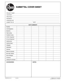
© Copyright 2026