
B . C
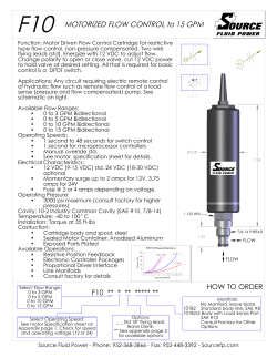
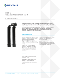
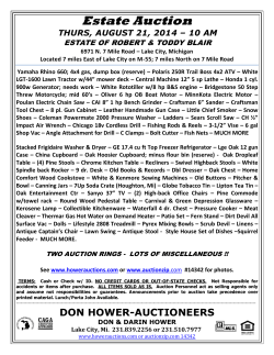
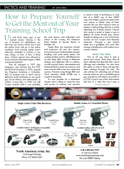
B.C. SPRINKLER IRRIGATION MANUAL Chapter 6 Editor Ted W. van der Gulik, P.Eng. Senior Engineer Authors Stephanie Tam, P.Eng. Water Management Engineer Andrew Petersen, P.Ag. Regional Resource Specialist Prepared and Web Published by Ministry of Agriculture 2014 ISSUE LIMITATION OF LIABILITY AND USER’S RESPONSIBILITY The primary purpose of this manual is to provide irrigation professionals and consultants with a methodology to properly design an agricultural irrigation system. This manual is also used as the reference material for the Irrigation Industry Association’s agriculture sprinkler irrigation certification program. While every effort has been made to ensure the accuracy and completeness of these materials, additional materials may be required to complete more advanced design for some systems. Advice of appropriate professionals and experts may assist in completing designs that are not adequately convered in this manual. All information in this publication and related materials are provided entirely “as is” and no representations, warranties or conditions, either expressed or implied, are made in connection with your use of, or reliance upon, this information. This information is provided to you as the user entirely at your risk. The British Columbia Ministry of Agriculture and the Irrigation Industry Association of British Columbia, their Directors, agents, employees, or contractors will not be liable for any claims, damages or losses of any kind whatsoever arising out of the use of or reliance upon this information. 6 GUN SYSTEM DESIGN In irrigation, the term gun is used to describe high volume sprinklers with discharge rates exceeding 50 US gpm. This chapter will discuss both stationary and travelling guns. Flow rates for guns can vary from 50 to 1,000 US gpm. Gun operating pressures may range from 40 to 120 psi, depending on the gun and type of nozzle selected. For travelling guns, the pressure required at the cart will include the nozzle pressure and friction losses through the hose delivering water from the machine to the gun. Water is usually supplied to the gun by above ground aluminum pipes or buried PVC pipe with hydrants spaced to meet the designed gun spacing. Figure 6.1 shows an example of a travelling gun system. Figure 6.1 Travelling Gun System 6.1 Nozzle Type Guns come in a variety of sizes, trajectory angles, and available nozzles. The trajectory angle is important in determining maximum spray height and distance of throw. Gun systems can utilize three types of nozzles: taper bore, taper ring, and ring nozzles. Taper bore nozzles provide better stream integrity and create maximum distance of throw with less distortion due to wind. See Tables 6.8 – 6.12. Chapter 6 Gun System Design 85 6.2 Operating Pressure Due to the large discharge rates of gun systems, higher operating pressures than sprinkler system are required to ensure good stream break up. An increase in pressure at the gun nozzle increases stream velocity which breaks the water into finer droplets. A fast stream velocity also provides a larger wetted diameter which helps to reduce the instantaneous application rate of the gun system. Proper selection of a gun operating pressure must take into account the nozzle type, soil and crop conditions. In most instances, large droplets are to be avoided as they cause soil compaction and may also cause crop damage. Gun systems are available in various trajectory angles. The higher trajectories maximize the wetted radius and allow for a near zero horizontal droplet velocity before reaching the crop. Lower trajectories operate more efficiently in windy conditions but do not have desirable droplet conditions. Lower trajectory guns need even higher operating pressures to ensure proper stream dispersal before contacting the crop. Table 6.1 indicates recommended minimum operating pressures for various gun sizes based on flow rate. Table 6.1 Recommended Minimum Operating Pressures for Gun Systems Flow Range [US gpm] Minimum Pressure [psi] 100 – 200 65 200 – 300 70 300 – 400 80 400 – 500 85 500+ 90 Special nozzle configurations have been developed to allow some gun systems to operate at pressures as low as 40 to 50 psi. Designers should check manufacturer's recommendations when using these low pressure gun systems. Warning – Gun System Design When operating gun systems near electrical transmission lines the operator must be very careful that the gun stream does not contact the power line. High voltage power lines can arc over to an irrigation stream if sufficient stream break up has not occurred. See Section 6.7 regarding minimum clearances between the jet stream and high voltage power lines. Selecting a gun spacing, flow rate, nozzle size and operating pressure can be simplified using Tables 6.9, 6.10, 6.11 and 6.12. The designer must be conversant with application rates, spacing selection, crop and soil parameters and gun operation before using these tables. Both instantaneous and overlap application rates should be calculated. 86 B.C. Sprinkler Irrigation Manual 6.3 Spacing Selection Gun systems are spaced on the same design parameters as sprinkler irrigation systems, as explained in Section 3.2. However, extra caution should be taken with guns as they are subject to very poor distribution uniformities during windy conditions, due to the large wetted radius and height of throw. Instantaneous application rates also increase substantially when guns are operated during windy conditions. It is strongly recommended that gun systems not be operated during windy conditions. Table 6.2 provides a guide to gun spacing. Since gun systems are susceptible to wind drift, the maximum sprinkler spacing should not exceed 50% of the wetted diameter and the lateral spacing should not exceed 65% of the wetted diameter. Travelling guns can be spaced up to 65% of the wetted diameter in appropriate conditions. Table 6.2 Gun Spacing Recommendations Gun Type Spacing as a Percentage of Wetted Diameter Stationary Gun Maximum sprinkler spacing = 50% Maximum lateral spacing = 65% Travelling Gun Maximum lane spacing = 65% 6.4 Application Rates Gun systems should be operated differently from conventional sprinkler systems due to the inherent high application rates that are produced. Irrigation set times are therefore much shorter to apply the amount of water required by a crop. To reduce the rate at which water is applied to the soil, two guns should never be operated simultaneously side by side. Even so, it is difficult to design stationary gun systems so that the maximum application rate does not exceed the values stated in Table 4.4. Exceeding these values slightly may be acceptable if the set time is less than four hours. However, moving a gun system every three hours may not be practical. To match the gun operation with soil conditions the instantaneous application rate and the overlap application rate should both be calculated as described in the next sections 6.5 and 6.6. Chapter 6 Gun System Design 87 6.5 Stationary Gun Stationary guns are usually used in smaller odd-shaped fields, or to irrigate corners or areas not covered by the primary irrigation system such as a centre pivot or a wheelmove. They provide advantages in tall crop situations but the difficulty of moving them is also a limiting factor. Stationary guns have the lowest application efficiency (58% when the system is designed correctly) of all sprinkler system due to their inherent poor uniformity; however, they are still used because of their low capital cost and flexibility in irrigating odd-shaped areas. Stationary guns should not be used if the goal is improved irrigation performance and efficiency. Typical Application Efficiencies of Sprinkler Irrigation Systems, Table 3.1 Instantaneous Application Rate Since two guns are not operating side by side at one time, the application rate formula that needs to be matched to the soil infiltration rate is different than it is for a sprinkler system. The instantaneous application rate is the actual rate that water is applied to the soil surface by the stationary gun while it is operating. It takes into account the wetted diameter of the gun and the amount of water discharged by the gun. The instantaneous application rate is the value that is checked against the maximum soil infiltration rate values shown in Table 4.4 to minimize runoff from the soil surface. For a stationary gun the Instantaneous Application Rate (IAR) can be calculated using equation 6.1: Equation 6.1 Instantaneous Application Rate IAR = where IAR = Q= Π= R= Q × 96.3 Π × R2 Instantaneous Application Rate [in/hr] Gun Flow Rate [US gpm] 3.14 (constant for an area of a circle) Wetted Radius of the Gun [ft] The instantaneous application rate may be increased significantly in windy conditions. The formula used above calculates the instantaneous application rate for perfect operating conditions. 88 B.C. Sprinkler Irrigation Manual Helpful Tips – Stationary Gun Operation The maximum soil infiltration rates shown in Table 4.4 are based on irrigation system operation times exceeding 4 hours. The infiltration capacity of a soil will be higher than the values shown for application times less than 4 hours. To reduce runoff consider the following: 1. Monitor the soil while the gun is running to determine the maximum run time that can be achieved before signs of puddling and runoff occur. 2. Determine the MSWD of the crop and soil to ensure the gun application rate and run time does not exceed the soil storage capacity. Overlap Application Rate Stationary gun sets should be spaced according to the recommendations in Table 6.2 to give sufficient overlap for proper uniformity. Insufficient overlap will result in parts of the field being under-irrigated. The aerial photo in Figure 6.2 illustrates a poor overlap. No circles should be shown in the photo if the gun system had been set up with a spacing that provided a proper overlap. Sprinkler Layout, Figure 5.1 For a stationary gun, the overlap application rate (OAR) is used to determine the total amount of water applied to the soil after all of the irrigation sets have been completed (the entire field has been irrigated). It will be used to determine the maximum irrigation interval. The overlap application rate is calculated using the gun spacing and flow rate as shown in Equation 6.2: Equation 6.2 Overlap Application Rate OAR = where OAR = Q= S1 = S2 = Q × 96.3 S1 × S 2 Overlap Application Rate [in/hr] Gun Flow Rate [US gpm] Gun Spacing along Lateral [ft] Lateral Spacing [ft] Chapter 6 Gun System Design 89 Figure 6.2 Poor Overlap in Stationary Gun Operation Application Efficiency Stationary gun systems are less efficient than sprinkler systems due to higher operating pressures, susceptibility to wind drift and high application rates. The set times for gun systems are usually shorter than sprinkler systems to avoid over application and runoff. For design purposes, if guns are spaced at no more than 50% of the wetted diameter, application efficiencies of 58% to 60% are the best that can be achieved for these kinds of systems. Typical Application Efficiencies of Sprinkler Irrigation Systems, Table 3.1 Helpful Tips – Stationary Gun System Design Stationary guns are often used in pastures where soils are compacted and the grass grown has a very shallow rooting depth. Take care to ensure that the MSWD is not exceeded. Most stationary gun systems should not run for more than four hours at one location. Automatic shutoffs should be incorporated where the system cannot be shutdown manually within this time frame. 90 B.C. Sprinkler Irrigation Manual Example 6.1 Stationary Gun in Merritt Question: A farmer in Merritt intends to use a stationary gun to grow grass in a series of four pastures. The soil is a deep loam. The pasture area is made up of four 5 acre parcels that are 660 ft x 330 ft each. Total pasture area is 1320 ft x 660 ft. What nozzle, spacing, pressure should be selected and what is the set time and irrigation interval? Information: Calculation: Step 1. Farm location Crop type Soil texture Rooting depth (RD, Table 4.1) Available water soil capacity (AWSC, Table 4.2) Availability coefficient (AC, Table 4.3) Maximum application rate (Max. AR, Table 4.4) Peak Evapotranspiration (Peak ET, Table 4.5) Estimated peak flow rate (Table 4.6) Irrigated acreage Application efficiency (AE, Table 3.1) 1 2 3 4 5 6 7 8 9 10 11 ft in/ft in/hr in/day US gpm acres Determine the maximum soil water deficit (MSWD), maximum irrigation interval (Max. II), and system peak flow rate. Equation 4.2 MSWD = Max II RD x AWSC x AC = 1.5 4 = 1.5 12 in 1.5 12 in 0.28 8 in/day 5.5 13 day Equation 4.3 = = = Equation 4.4 Peak = Flow Rate Step 2. Merritt Pasture Loam 1.5 2.0 0.50 0.35 0.28 7.0 20 0.58 ft x 5 2.0 in/ft x 6 0.50 MSWD Peak ET Estimated Peak Flow Rate Requirement per Acre x Irrigated Area = 7.0 9 US gpm x = 140 14 US gpm 20 10 acres Select a gun nozzle, and determine gun set spacing. 136 Gun flow rate (Q, Table 6.9) 283 Wetted diameter (Table 6.9) Nozzle type (Table 6.9) Taper bore 0.75 Nozzle size (Table 6.9) 70 Operating pressure (Table 6.9) 15 16 17 18 19 US gpm ft in psi Chapter 6 Gun System Design 91 Wetted Radius (R) = Gun Spacing (S 1 ) = 50% x = 142 = Lateral Spacing (S 2 ) Step 3. 50% of wetted diameter 16 283 20 ft ft 50% of wetted diameter = 50% x = 142 ft = 140 21 = 16 283 ft ft (designer select) 65% of wetted diameter = 65% x = 184 ft = 180 22 16 283 ft ft (designer select) Determine the set time. Equation 6.1 IAR = = = Equation 6.2 OAR = = = Q x 96.3 2 ΠxR 15 136 Π x( 20 142 23 0.21 US gpm x 96.3 ft) 2 in/hr must be less than Max AR of 0.35 7 in/hr Q x 96.3 S1 x S2 15 136 140 21 ft x 0.52 24 in/hr US gpm x 96.3 180 22 ft The system needs to be designed to match up with MSWD; therefore, NWR = MSWD. Equation 5.3 GWR = NWR AE = MSWD AE 1.5 4 0.58 11 = 2.6 25 in = GWR OAR 2.6 25 in 0.52 24 in/hr 5.0 26 hr = Set Time = = 92 B.C. Sprinkler Irrigation Manual in Step 4. Determine the irrigation interval. Grid Size Field Size = S1 x S2 = 140 = 1,320 = = = # of Sets per Day 22 ft 27 ft x Field Length S1 x 1,320 27 ft 140 21 ft 35 29 660 28 ft Field Width S2 x 660 28 ft 180 22 ft sets 24 hr = 5.0 26 hr 4.8 30 sets/day # of Sets # of Sets per Day = = = IMPORTANT: 180 24 hr Set time = = Irrigation Interval ft x Field Length x Field Width = # of Sets 21 35 29 sets 4 30 sets/day 9 31 day is over the Max. II of 5.5 13 day This example shows the problems that are inherent with Stationary Guns. The poor efficiency, difficulty in matching gun spacing to fit the areas to be irrigated, and inability to move the system as often as required usually mean that the area is not irrigated as well as it should be. In this case, the irrigation interval is exceeded even if the system could be moved every five hours (set time) which is not practical and not likely. 6.6 Travelling Gun Since travelling guns move during application, the application uniformity is much better than a stationary gun system. The efficiency of application may also be slightly higher as the potential for runoff is reduced. The maximum application efficiency for a travelling gun as shown in Table 3.1 is 65% for most B.C. conditions. As indicated in Figure 6.3, travelling guns use a hose to drag the gun cart across the field. Hose and machine friction losses must therefore be taken into account when selecting machine connection pressure, ensuring that the Chapter 6 Gun System Design 93 nozzle operates above the minimum pressures required as shown in Table 6.1. Travelling gun systems are susceptible to striking electrical transmission lines. The design standards shown in Section 6.7 should be followed when designing a system in the vicinity of high voltage power lines. Travelling gun systems overcome the problem of the short set time generally required with stationary gun designs. The travelling gun system can irrigate larger parcels of land during one irrigation set. Flow rates generally range from a minimum of 50 US gpm up to 700 US gpm. For agricultural irrigation purposes in B.C., travelling gun systems in the 100 to 350 US gpm range are often used. Figure 6.3 shows how a travelling gun is operated to irrigate a field. Figure 6.3 Hard Hose Reel Machine Layout Travel Speed The travel speed of a travelling gun can be adjusted to vary the amount of water applied. Adjustments to the travel speed can also be used to help reduce or eliminate puddling and runoff. Set times can be selected to suit the farm operation, however it is important that the irrigation system design and operation allows the machine to operate at least 23 hours per day to maximize efficiency of use. If total operating times are less than 23 hours per day then a peak flow rate per acre exceeding the values estimated in Table 4.6 may result. The 23 hour set time is selected to allow time for moving the gun to the next set. The travel speed required is determined from Equation 6.3. 94 B.C. Sprinkler Irrigation Manual Equation 6.3 Travel Speed (T) T= where T= Field length = Set time = Field Length Set Time gun cart travel speed [ft/hr] length of field [ft] time to irrigate one set [hr] Amount Applied per Irrigation The amount applied by a travelling gun system is dependent upon the travel speed of the gun cart, the gun flow rate and gun spacing. The amount applied by the machine can be calculated by using Equation 6.4. Equation 6.4 Gross Water Applied (GWA) GWA = where GWA = Q= S= T= Q × 96.3 S ×T gross water applied during an irrigation interval [in] gun flow rate [US gpm] lane spacing between sets [ft] gun cart travel speed [ft/hr] As a quick guide, Table 6.3 provides information on the GWA by a travelling gun for various flow rates, lane spacings and travel speeds. The net water applied (NWA) is calculated by applying the application efficiency of the gun to the gross water applied (GWA). See Equation 6.5. Equation 6.5 Net Water Applied (NWA) NWA = GWA × AE where NWA = GWA = AE = net water applied during an irrigation interval [in] gross water applied during an irrigation interval [in] application efficiency [% in decimal form] Chapter 6 Gun System Design 95 Table 6.3 Depth of Water Applied by Travelling Guns (Inches) Travel Speed [ft/hr] Flow per Gun [US gpm] Lane Spacing [ft] 20 30 40 60 80 100 120 150 180 100 120 135 150 4.01 3.56 3.21 2.68 2.38 2.14 2.00 1.78 1.60 1.33 1.18 1.07 1.00 0.89 0.80 0.80 0.71 0.64 0.67 0.59 0.54 0.54 0.48 0.43 0.43 0.39 0.36 150 135 150 165 180 5.35 4.82 4.37 4.01 3.57 3.21 2.92 2.68 2.68 2.41 2.19 2.00 1.78 1.61 1.46 1.34 1.34 1.20 1.09 1.00 1.07 0.96 0.88 0.80 0.89 0.80 0.73 0.67 0.71 0.64 0.58 0.54 0.59 0.54 0.49 0.45 200 150 165 180 200 – 5.83 5.35 4.81 4.28 3.89 3.56 3.21 3.21 2.92 2.68 2.40 2.14 1.95 1.78 1.60 1.61 1.46 1.34 1.20 1.28 1.17 1.07 0.96 1.07 0.97 0.89 0.80 0.86 0.78 0.71 0.64 0.71 0.65 0.59 0.54 250 160 180 200 220 – – – 5.47 5.01 4.46 4.00 3.65 3.76 3.34 3.00 2.74 2.50 2.23 2.00 1.82 1.38 1.67 1.50 1.34 1.50 1.34 1.20 1.09 1.25 1.11 1.00 0.91 1.00 0.89 0.80 0.73 0.84 0.74 0.67 0.61 300 180 200 220 240 – – – – 5.35 4.81 4.37 4.00 4.01 3.61 3.28 3.00 2.68 2.40 2.19 2.00 2.00 1.81 1.64 1.50 1.60 1.44 1.31 1.20 1.34 1.20 1.09 1.00 1.07 0.96 0.88 0.80 0.89 0.80 0.73 0.67 350 180 200 220 240 – – – – – 5.61 5.11 4.68 4.68 4.21 3.83 3.51 3.12 2.81 2.55 2.34 2.34 2.11 1.92 1.76 1.87 1.68 1.53 1.40 1.56 1.40 1.28 1.17 1.25 1.12 1.02 0.94 1.04 0.94 0.85 0.78 400 200 220 240 260 – – – – – 5.84 5.35 4.94 4.81 4.37 4.01 3.70 3.21 2.92 2.68 2.47 2.41 2.19 2.00 1.85 1.92 1.75 1.60 1.48 1.60 1.46 1.34 1.23 1.28 1.17 1.07 0.99 1.07 0.97 0.89 0.82 450 200 220 240 260 5.42 4.92 4.51 4.17 4.33 3.94 3.61 3.33 3.61 3.28 3.00 2.78 2.71 2.46 2.26 2.08 2.17 1.97 1.81 1.67 1.81 1.64 1.50 1.39 1.55 1.41 1.29 1.19 1.35 1.23 1.13 1.04 1.20 1.09 1.00 0.93 500 220 240 260 280 5.47 5.01 4.62 4.30 4.38 4.01 3.70 3.44 3.64 3.34 3.09 2.87 2.74 2.51 2.31 2.15 2.18 2.00 1.85 1.71 1.82 1.67 1.54 1.43 1.56 1.43 1.32 1.23 1.37 1.25 1.16 1.07 1.22 1.11 1.03 0.95 550 220 240 260 280 6.01 5.51 5.09 4.73 4.81 4.41 4.07 3.78 4.01 3.67 3.40 3.15 3.00 2.76 2.55 2.36 2.40 2.20 2.04 1.89 2.00 1.84 1.70 1.58 1.71 1.58 1.46 1.35 1.50 1.38 1.27 1.18 1.34 1.23 1.13 1.05 600 240 260 280 300 6.02 5.55 5.15 4.81 4.82 4.44 4.13 3.85 4.01 3.70 3.44 3.21 3.00 2.78 2.58 2.41 2.40 2.22 2.06 1.92 2.00 1.85 1.72 1.60 1.72 1.59 1.47 1.38 1.50 1.39 1.29 1.20 1.34 1.23 1.15 1.07 650 240 260 280 300 – 6.02 5.59 5.22 5.21 4.82 4.47 4.17 4.35 4.01 3.73 3.48 3.26 3.00 2.79 2.61 2.60 2.40 2.24 2.09 2.17 2.00 1.86 1.74 1.86 1.72 1.60 1.49 1.63 1.50 1.40 1.30 1.45 1.34 1.24 1.16 700 260 280 300 320 – 6.02 5.62 5.27 5.19 4.82 4.49 4.21 4.32 4.01 3.75 3.51 3.24 3.00 2.81 2.63 2.59 2.40 2.24 2.10 2.16 2.00 1.87 1.75 1.85 1.72 1.61 1.50 1.62 1.50 1.40 1.32 1.44 1.34 1.25 1.17 Note: The blanks indicate depths of application exceeding 6 inches, which will exceed the MSWD for most plant and soil combinations; therefore, are not recommended. 96 B.C. Sprinkler Irrigation Manual Instantaneous Application Rate Part circle guns are used on travelling gun systems to ensure that the cart is pulled along dry ground, ahead of the area being irrigated. This also ensures that the gun does not irrigate beyond the field boundary when the gun cart approaches the machine. The instantaneous application rate (IAR) of the gun will be affected by the part circle. For a proper design, the IAR must not exceed the maximum application rate for the type of soil texture and field type. The part circle of the gun should be maximized while still allow the cart to be dragged through the non-irrigated area. Equation 6.6 illustrates how to determine the instantaneous application rate for part circle guns. Equation 6.6 Instantaneous Application Rate (IAR) IAR = where IAR = Q= R= c= Q × 96.3 ∏ ×R 2 × c Instantaneous application rate [in/hr] gun flow rate [US gpm] wetted radius of the gun [ft] percentage of full circle covered by gun [% in decimal form] Table 6.4 can be used as a guide to determine the instantaneous application rate of a travelling gun. The application rates shown are theoretical values that can be obtained in perfect operating conditions. Windy conditions may substantially affect the application rates shown. The gun radius values indicated are average values taken from manufacturer's specifications. Helpful Tips – Travelling Gun System Design Travelling gun machines are often designed to swivel the machine 180o so that the gun cart can be pulled out in both directions without having to move the machine. If the field is large enough then consider putting the mainline down the middle to utilize this option. It will reduce moving set up time. The travel speed selected should ensure that the soil and crop MSWD is not exceeded. Note that in Table 6.4 the IAR of the gun is reduced as the arc of the gun is increased. Designers should consider increasing the arc if possible where the IAR of the gun is exceeding the maximum soil infiltration rate. Chapter 6 Gun System Design 97 Table 6.4 Instantaneous Application Rates for Part Circle Guns Gun Flow Rate [US gpm] Gun Radius [ft] 100 Instantaneous Application Rate [in/hr] 180o arc (c = 0.5) 240o arc (c = 0.67) 130 0.36 0.27 150 150 0.41 0.31 200 160 0.48 0.36 250 175 0.50 0.37 300 185 0.54 0.40 350 190 0.59 0.44 400 200 0.61 0.46 450 210 0.63 0.47 500 215 0.66 0.49 550 220 0.70 0.52 600 225 0.73 0.54 650 230 0.75 0.56 700 235 0.78 0.58 Helpful Tips – Travelling Gun System Design Example 6.2 In example 6.2, note that the MSWD for the crop and soil is 3.0 inches and the maximum irrigation interval is 14 days if the soil is filled up entirely to the MSWD. However, for the travelling gun system, since the net amount of water applied is 1 inch, the actual irrigation interval during peak conditions is 5.5 days. This indicates that slower travel speeds could be used to increase the amount of water applied and lengthening the actual irrigation interval. No more than 3.0 inches could be applied at one time however or the MSWD would be exceeded. Helpful Tips – Irrigation Design Parameters The travelling gun irrigation design plan shown here is also provided in Appendix C with the corresponding design parameters shown on the adjacent page. The design parameter summary is useful for evaluating the irrigation system design and performance characteristics. This information should be included with every irrigation system plan. 98 B.C. Sprinkler Irrigation Manual Example 6.2 Travelling Gun in Armstrong Question: The farmer in Armstrong (examples 4.1, 4.3 and 4.5) wants to use a travelling gun to irrigate three 40-acre (1,320 ft x 1,320 ft) alfalfa fields consisting of deep sandy loam soil. What nozzle, pressure and lane spacing will be required per travelling gun? What would will be the net water applied per irrigation? Information: Farm location Armstrong 1 Alfalfa 2 Crop type SL 3 Soil texture 3.0 4 Maximum soil water deficit (MSWD, Box 8, Example 4.1) 14 5 Maximum irrigation interval (Max. II, Box 8, Example 4.3) 0.45 6 Maximum application rate (Max. AR, Table 4.4) 0.21 7 Peak Evapotranspiration (Peak ET, Table 4.5) 5.25 8 Estimated peak flow rate (Table 4.6) 40 9 Irrigated area per field 1,320 10 Field length 0.65 11 Application efficiency (AE, Table 3.1) in days in/hr in/day US gpm acres ft The set time for a travelling gun is generally 23.5 hours with 0.5 hour for moving the gun to the next set. 23.5 12 hr Set time Calculation: Step 1. Determine the system peak flow rate. Equation 4.4 Peak = Flow Rate Step 2. Estimated Peak Flow Rate Requirement per Acre x Irrigated Area = 5.25 8 US gpm x = 210 13 US gpm 9 40 acres Select a gun nozzle, and determine gun set spacing. 210 Gun flow rate (Q, Table 6.10) 335 Wetted diameter (Table 6.10) Nozzle type (Table 6.10) Taper bore 0.9 Nozzle size (Table 6.10) 80 Nozzle pressure (Table 6.10) 0.67 c value Wetted Radius (R) = US gpm ft in psi 50% of wetted diameter = 50% x = 168 Maximum Lane Spacing = 14 15 16 17 18 19 14 335 20 ft ft 60% of wetted diameter = 60% x = 201 14 335 21 ft ft A round number will be easier to work with in the field. For convenience, set Lane Spacing = 200 22 ft Chapter 6 Gun System Design 99 Step 3. Check the Instantaneous Application Rate (IAR). o o From Table 6.4, IAR = 0.48 in/hr for a 180 arc, and IAR = 0.36 in/hr for a 240 arc. The maximum application rate cannot be exceeded. Therefore, the gun should be operated o with at least a 240 arc in this case. Gun trajectory Equation 6.6 IAR = = Step 4. 23 Q x 96.3 2 ΠxR xc Π x( = 240o 210 14 US gpm x 96.3 168 20 ft) x 24 0.34 2 0.67 19 in/hr which must be less than Max AR of 0.45 6 in/hr Determine the travel speed (T), gross water applied (GWA), and net water applied (NWA). Equation 6.3 Field Length T = Set Time = = Equation 6.4 GWA = = = 1,320 10 ft 23.5 12 hr 56 25 ft/hr Q x 96.3 SxT 14 210 200 22 ft x 1.8 26 in US gpm x 96.3 56 25 0.65 11 ft/hr Equation 6.5 NWA = GWA x AE = 1.8 26 in x = 1.17 27 in 1.17 27 in 0.21 7 in/d 5.6 28 days which is less than Max II of Equation 5.2 II = = = Note: 100 NWA ET 14 5 day With a spacing of 200 feet the unit will take 6.5 days to cover the field. In hot weather the crop water demand may be greater than the irrigation systems ability to supply water. If the travelling gun application rate exceeds the soil capability, even at arcs approaching full circle, the gun travel speed should be increased to shorten the duration of application as much as possible. B.C. Sprinkler Irrigation Manual Figure 6.4 Chapter 6 Gun System Design 101 6.7 System Design Consideration near Electrical Transmission Lines Striking electrical transmission lines with an irrigation water jet can cause current transfers that may be dangerous to an operator touching the machine. Current transfers can occur in the following conditions: Direct contact of the irrigation system with the transmission line. Leakage current – the result of an alternative path being provided for the conduction of electrical current. This situation can arise when concentrated jets of water from the irrigation system come into contact with transmission line conductors. (Current flows from the power line to the nozzle through the water jet). Flashovers – occur when the insulating qualities of the air are not great enough to overcome the potential difference between a conductor and objects at another potential. Flashovers can occur between conductor to tower, phase to phase and conductor to ground due to a water jet interacting with the power line. An irrigation water jet striking a transmission line is also a nuisance to the power utility because: The force exerted on the lines by the water jet can be many times the weight load or expected wind loading. Swaying of the conductors can result. A flashover can create power outages which may interrupt service to thousands of customers. Minimum Clearance Standards To ensure safe operation of irrigation equipment near transmission lines, minimum separation distances are required from the gun to the transmission lines. The clearance required between the water jet and the live conductors is a function of the voltage of the conductor. The values shown in Table 6.5 are the minimum acceptable clearances provided by BC Hydro for various line voltages. The total water spray height includes the working height of the nozzle plus the maximum stream height above the nozzle. Two irrigation system types that have working heights which interact with power lines are centre pivots and gun systems. Working heights of centre pivot systems range from 12 to 25 feet (3.6 to 7.6 metres); however, most pivots are less than 14 feet (4.2 metres) in height. The working height of a travelling gun ranges from 6 to 11 feet (1.8 to 3.3 metres). These heights are required to permit these systems to operate over crops such as corn, providing good uniformity without damaging the crop. 102 B.C. Sprinkler Irrigation Manual Table 6.5 Irrigation Water Jet to Power Line Clearance Standards Line Voltage [kV] Phase Spacing (S) [ft] Min. Mid-Span Height (H) [ft] Conductor-to-Water Clearance (Y) [ft] Allowable Stream Spray Height (L) [ft] 69 5.0 18.0 2.0 16.0 138 14.0 22.6 3.0 19.6 230 18.0 24.3 5.0 19.3 387 22.0 25.6 6.2 19.4 345 34.8 28.5 7.5 21.0 500 45.0 32.8 10.5 22.3 Source: BC Hydro Calculating Maximum Stream Height While the working height of a nozzle can be measured easily, the maximum stream height is more difficult. The maximum stream height is a function of the type of sprinkler, angle of trajectory, nozzle size and operating pressure. Manufacturers indicate maximum stream heights for various impact sprinklers but not for giant guns. Nelson Irrigation Corporation has developed a formula for determining the maximum stream height and location of maximum stream height for gun systems based on the wetted diameter and pressure (assuming that the gun is operating on level ground). Equation 6.7 Stream Height where X= Z= D= C= K= (a) X = 0.3 × D (b) Z = C × D − K × D2 Horizontal distance from the nozzle at which maximum stream height occurs (ft) Maximum stream height above sprinkler nozzle (ft) Wetted diameter (ft) Dimensionless factor dependent on barrel trajectory Dimensionless factor dependent on barrel trajectory and operating pressure Figure 6.4 shows the various parameters used in Equation 6.7. The dimensionless factors “C” and “K” can be determined from Table 6.6 and Table 6.7. Chapter 6 Gun System Design 103 Figure 6.5 Schematic Indicating Gun Spray Trajectories Table 6.6 C Values Trajectory 15o 18o 21o 24o 27o C Value 0.067 0.081 0.096 0.111 0.127 Source: Nelson Irrigation Corporation Table 6.7 K Values Trajectory o o PSI 15 18 21o 24o 27o 40 0.181 x 10⁻³ 0.187 x 10⁻³ 0.194 x 10⁻³ 0.203 x 10⁻³ 0.213 x 10⁻³ 68 0.121 x 10⁻³ 0.125 x 10⁻³ 0.129 x 10⁻³ 0.135 x 10⁻³ 0.142 x 10⁻³ 80 0.091 x 10⁻³ 0.093 x 10⁻³ 0.097 x 10⁻³ 0.101 x 10⁻³ 0.107 x 10⁻³ 100 0.072 x 10⁻³ 0.075 x 10⁻³ 0.078 x 10⁻³ 0.081 x 10⁻³ 0.085 x 10⁻³ Source: Nelson Irrigation Corporation Helpful Tips – Distance from Electrical Transmission Line The maximum stream height and the distance this height occurs from the nozzle are useful when designing systems that are close to transmission lines. However as demonstrated in Example 6.3, the distance the gun cart must be kept from a transmission line is difficult to determine as there is no calculation for determining how fast the stream height diminishes after the maximum height is reached. Field observation should also be used in addition to the calculations. The transmission line height will be the lowest on the hottest day of the year. The minimum setback distance will be the required clearance distance plus the distance from the cart that the maximum stream height occurs. Actual distance should probably be further at a point where good stream breakup has occurred. The field should be staked at the point where the gun should be towed to. 104 B.C. Sprinkler Irrigation Manual Example 6.3 Maximum Stream Height Question: What is the maximum stream height of the gun system selected in example 6.2 if the cart height is 7 ft? The nozzle selected was a 0.9-inch taper bore nozzle operating at 80 psi with a o 24 trajectory. The flow rate is 210 US gpm with a wetted diameter of 335 ft. What is the distance that the gun cart should be kept from a 500 kV transmission line? Information: Flow rate Wetted diameter (D) C value (Table 6.6) Cart height 210 335 0.111 7 1 2 3 4 US gpm ft ft Select a K value for the pressure that is closest to 80 psi: K value (Table 6.7) 0.101x10⁻³ Calculation: 5 Equation 6.3 (a) X = 0.3 x D = 0.3 x = 100 2 335 6 ft ft Equation 6.3 (b) 2 Z = CxD–KxD Total Height Answer: = 0.111 3 = 25.9 7 = x 335 2 ft – 0.101x10⁻³ 5 x( 335 2 ft) 2 ft Cart Height + Z = 7 4 ft + = 32.9 8 ft 25.9 7 ft A maximum stream height of 25.9 ft occurs 100 ft from the gun operating a 0.9 inch taper bore o nozzle at 80 psi with a 24 trajectory. Adding the cart height of 7 ft means the total height is 32.9 ft. From Table 6.5, the mid-span height (H) of a 500kV transmission line is 32.8 ft, approximately the same height of the gun stream. The conductor to water clearance (Y) is a minimum of 10.5 ft. Visual observation will be required to determine where a safe distance for the gun cart to start irrigating will be. The minimum distance will be 110.5 ft away from the transmission line. (100 + 10.5). Chapter 6 Gun System Design 105 Table 6.8 provides close approximations for stream heights and the distance the height occurs from the nozzle for various nozzles, pressures, flow rates and nozzle trajectories. Equations 6.7 (a) and 6.7 (b) were used to determine these values. The nozzle height from the ground must be added to these values to get the overall height. Comparing values in Table 6.8 with clearance requirements in Table 6.5, only the smaller nozzles with lower trajectories have stream heights that may go under the larger transmission lines. Table 6.8 Stream Trajectory Data for Giant Guns with Taper Bore Nozzles Nozzle 0.6” 0.7” 0.8” 0.9” 1.0” 1.1” 1.3” 1.6” Pressure [psi] Flow Rate [US gpm] 60 81 80 94 60 110 80 128 60 143 80 165 60 182 80 210 60 225 80 260 100 290 80 330 100 370 80 445 100 500 80 675 100 755 Values are approximations only. 106 B.C. Sprinkler Irrigation Manual Nozzle Trajectory [o] Wetted Diameter (D) [ft] Radial Distance to Maximum Stream Height (x) [ft] Maximum Stream Height (Z) [ft] 18 21 24 18 21 24 229 233 240 251 253 260 69 70 72 75 76 78 12.0 15.4 18.9 14.5 18.1 22.0 18 21 24 18 21 24 252 257 265 278 281 290 76 77 80 83 84 87 12.5 16.1 19.9 15.3 19.3 23.7 18 21 24 18 21 24 272 276 285 302 304 310 82 83 86 91 91 93 12.8 16.7 20.7 16.0 20.2 24.7 18 21 24 18 21 24 287 296 305 323 328 335 86 89 92 97 98 101 13.0 17.1 21.3 16.5 21.0 25.9 21 24 21 24 21 24 315 325 344 355 364 375 95 98 103 107 109 113 17.4 21.8 21.5 26.7 24.6 30.2 21 24 27 21 24 27 375 387 395 400 412 420 113 116 119 120 124 126 22.4 27.8 33.5 25.9 32.0 38.3 21 24 27 21 24 27 409 421 430 437 451 460 123 126 129 131 135 138 23.0 28.8 34.8 27.1 33.6 40.4 21 24 27 21 24 27 470 475 485 494 510 520 141 143 146 148 153 156 23.7 29.9 36.4 28.4 35.5 43.1 Table 6.9 Gun Nozzle Performance - Series 75 Guns 24o Trajectory TAPER RING NOZZLES 0.5” Flow Path 0.55” 0.6” 0.65” 0.7” 0.75” PSI GPM DIA GPM DIA GPM DIA GPM DIA GPM DIA GPM DIA 35 40 164’ 49 172’ 59 178’ 69 191’ 81 196’ 93 202’ 40 43 171’ 52 180’ 63 190’ 74 198’ 87 204’ 98 45 46 180’ 56 189’ 67 198’ 79 206’ 91 214’ 104 50 48 186’ 59 195’ 70 203’ 83 212’ 95 220’ 55 50 193’ 62 203’ 74 213’ 87 221’ 100 60 53 198’ 64 208’ 77 220’ 91 228’ 65 55 205’ 67 216’ 80 227’ 95 70 57 210’ 69 221’ 83 232’ 75 59 217’ 72 228’ 86 80 61 222’ 74 234’ 89 0.8” GPM DIA 213’ 112 221’ 223’ 118 230’ 109 230’ 123 237’ 230’ 115 239’ 130 247’ 104 237’ 120 245’ 136 254’ 237’ 109 247’ 125 254’ 142 263’ 98 243’ 113 254’ 129 260’ 147 270’ 239’ 101 250’ 117 261’ 134 268’ 153 277’ 244’ 105 256’ 121 266’ 138 274’ 158 283’ The diameter of flow is approximately 3% less for the 21o trajectory angle, and 6% less for 18o. Source: Nelson Irrigation Corporation Chapter 6 Gun System Design 107 Table 6.10 Gun Nozzle Performance – Series 100 Guns 24o Trajectory Flow Path TAPER BORE NOZZLES 0.50” PSI GPM 0.55” 0.60” 0.65” 0.70” 0.75” 0.80” 0.85” 0.90” DIA GPM DIA GPM DIA GPM DIA GPM DIA GPM DIA GPM DIA GPM DIA GPM DIA 1.0” GPM DIA 40 47 191’ 57 202’ 66 213’ 78 222’ 91 230’ 103 240’ 118 250’ 134 256’ 152 262’ 50 50 205’ 64 215’ 74 225’ 87 235’ 100 245’ 115 256’ 130 265’ 150 273’ 165 280’ 204 300’ 60 55 215’ 69 227’ 81 240’ 96 250’ 110 260’ 126 270’ 143 280’ 164 288’ 182 295’ 224 316’ 70 60 225’ 75 238’ 88 250’ 103 263’ 120 275’ 136 283’ 155 295’ 177 302’ 197 310’ 243 338’ 80 64 235’ 79 248’ 94 260’ 110 273’ 128 285’ 146 295’ 165 305’ 189 314’ 210 325’ 258 354’ 90 68 245’ 83 258’ 100 270’ 117 283’ 135 295’ 155 306’ 175 315’ 201 326’ 223 335’ 274 362’ 100 72 255’ 87 268’ 106 280’ 123 293’ 143 305’ 163 316’ 185 325’ 212 336’ 235 345’ 289 372’ 110 76 265’ 92 278’ 111 290’ 129 303’ 150 315’ 171 324’ 195 335’ 222 344’ 247 355’ 304 380’ TAPER RING NOZZLES 0.64” PSI GPM Flow Path 0.68” 0.72” 0.76” 0.80” 0.84” 0.88” 0.92” 0.96” DIA GPM DIA GPM DIA GPM DIA GPM DIA GPM DIA GPM DIA GPM DIA GPM DIA 40 67 212’ 76 219’ 86 225’ 98 233’ 110 242’ 125 250’ 136 254’ 151 259’ 166 275’ 50 75 224’ 85 231’ 97 240’ 110 250’ 123 258’ 139 266’ 152 271’ 169 279’ 185 288’ 60 83 239’ 94 246’ 106 254’ 120 264’ 135 273’ 153 281’ 167 286’ 186 294’ 203 303’ 70 89 249’ 101 259’ 114 268’ 130 277’ 146 286’ 165 295’ 180 300’ 200 309’ 219 320’ 80 95 259’ 108 269’ 122 278’ 139 288’ 156 297’ 176 306’ 193 313’ 214 324’ 235 336’ 90 101 268’ 115 278’ 130 289’ 147 299’ 166 308’ 187 317’ 204 324’ 227 334’ 249 345’ 100 107 278’ 121 288’ 137 298’ 155 308’ 175 318’ 197 327’ 216 334’ 240 344’ 262 355’ 110 112 288’ 127 298’ 143 308’ 163 317’ 183 326’ 207 336’ 226 342’ 251 353’ 275 364’ RING NOZZLES 0.71” PSI GPM Flow Path 0.77” 0.81” 0.86” 0.89” 0.93” 0.96” DIA GPM DIA GPM DIA GPM DIA GPM DIA GPM DIA GPM DIA 40 66 208’ 78 212’ 91 215’ 103 224’ 118 235’ 134 238’ 152 242’ 50 74 220’ 88 225’ 100 230’ 115 240’ 129 250’ 150 255’ 167 260’ 60 81 235’ 96 240’ 110 245’ 125 260’ 141 270’ 164 275’ 183 280’ 70 88 245’ 104 250’ 118 260’ 135 275’ 152 290’ 177 295’ 198 300’ 80 94 255’ 111 265’ 127 275’ 145 285’ 163 300’ 189 305’ 211 315’ 90 99 265’ 117 275’ 134 285’ 154 295’ 173 310’ 201 315’ 224 325’ 100 105 270’ 124 280’ 142 295’ 162 305’ 182 320’ 212 325’ 236 335’ 110 110 275’ 130 290’ 149 305’ 170 315’ 191 325’ 222 335’ 248 345’ The diameter of flow is approximately 3% less for the 21o trajectory angle, and 6% less for 18o. 108 B.C. Sprinkler Irrigation Manual Source: Nelson Irrigation Corporation Table 6.11 Gun Nozzle Performance - Series 150 Guns 24o Trajectory Flow Path TAPER BORE NOZZLES 0.70” 0.80” 0.90” 1.0” 1.1” 1.2” 1.3” 1.4” PSI GPM DIA GPM DIA GPM DIA GPM DIA GPM DIA GPM DIA GPM DIA GPM DIA 50 100 250’ 130 270’ 165 290’ 205 310’ 255 330’ 300 345’ 350 360’ 408 373’ 60 110 265’ 143 285’ 182 305’ 225 325’ 275 345’ 330 365’ 385 380’ 446 396’ 70 120 280’ 155 300’ 197 320’ 245 340’ 295 360’ 355 380’ 415 395’ 483 412’ 80 128 290’ 165 310’ 210 335’ 260 355’ 315 375’ 380 395’ 445 410’ 516 427’ 90 135 300’ 175 320’ 223 345’ 275 365’ 335 390’ 405 410’ 475 425’ 547 442’ 100 143 310’ 185 330’ 235 355’ 290 375’ 355 400’ 425 420’ 500 440’ 577 458’ 110 150 320’ 195 340’ 247 365’ 305 385’ 370 410’ 445 430’ 525 450’ 605 471’ 120 157 330’ 204 350’ 258 375’ 320 395’ 385 420’ 465 440’ 545 460’ 632 481’ TAPER RING NOZZLES 0.88” Flow Path 0.96” 1.04” 1.12” 1.2” 1.28” 1.36” PSI GPM DIA GPM DIA GPM DIA GPM DIA GPM DIA GPM DIA GPM DIA 50 135 270’ 164 286’ 196 302’ 233 318’ 274 333’ 319 347’ 369 358’ 60 148 284’ 179 301’ 214 317’ 255 334’ 301 351’ 350 367’ 405 378’ 70 159 299’ 194 315’ 231 331’ 276 349’ 325 366’ 378 382’ 437 393’ 80 170 310’ 207 330’ 247 346’ 295 364’ 347 381’ 404 397’ 467 409’ 90 181 320’ 220 340’ 262 357’ 313 377’ 368 396’ 429 411’ 495 424’ 100 191 329’ 231 350’ 277 366’ 330 386’ 388 405’ 452 423’ 522 436’ 110 200 339’ 243 359’ 290 376’ 346 397’ 407 416’ 474 433’ 548 446’ 120 209 349’ 253 369’ 303 386’ 361 407’ 425 426’ 495 443’ 572 457’ RING NOZZLES 0.86” Flow Path 0.97” 1.08” 1.18” 1.26” 1.34” 1.41” 1.47” PSI GPM DIA GPM DIA GPM DIA GPM DIA GPM DIA GPM DIA GPM DIA GPM DIA 50 100 245’ 130 265’ 165 285’ 205 300’ 255 320’ 300 335’ 350 350’ 385 353’ 60 110 260’ 143 280’ 182 300’ 225 315’ 275 335’ 330 350’ 385 365’ 423 368’ 70 120 270’ 155 290’ 197 310’ 245 330’ 295 350’ 355 365’ 415 380’ 458 383’ 80 128 280’ 165 300’ 210 320’ 260 340’ 315 360’ 380 380’ 445 395’ 490 399’ 90 135 290’ 175 310’ 223 330’ 275 350’ 335 370’ 405 390’ 475 405’ 522 409’ 100 143 300’ 185 320’ 235 340’ 290 360’ 355 380’ 425 400’ 500 415’ 550 419’ 110 150 310’ 195 330’ 247 350’ 305 370’ 370 390’ 445 410’ 525 425’ 577 429’ 120 157 315’ 204 335’ 258 360’ 320 380’ 385 400’ 465 420’ 545 435’ 603 439’ The diameter of throw is approximately 3% less for the 21o trajectory angle. Source: Nelson Irrigation Corporation Chapter 6 Gun System Design 109 Table 6.12 Gun Nozzle Performance – Series 200 Guns 27o Trajectory Flow Path TAPER BORE NOZZLES 1.05” 1.1” 1.2” 1.3” 1.4” 1.5” 1.6” 1.75” 1.9” PSI GPM DIA GPM DIA GPM DIA GPM DIA GPM DIA GPM DIA GPM DIA GPM DIA GPM DIA 60 250 345’ 285 355’ 330 375’ 385 390’ 445 410’ 515 430’ 585 445’ 695 470’ 825 495’ 70 270 360’ 310 380’ 355 395’ 415 410’ 480 430’ 555 450’ 630 465’ 755 495’ 890 515’ 80 290 375’ 330 395’ 380 410’ 445 430’ 515 450’ 590 470’ 675 485’ 805 515’ 950 535’ 90 310 390’ 350 410’ 405 425’ 475 445’ 545 465’ 625 485’ 715 505’ 855 535’ 1005 555’ 100 325 400’ 370 420’ 425 440’ 500 460’ 575 480’ 660 500’ 755 520’ 900 550’ 1060 575’ 110 340 410’ 390 430’ 445 450’ 525 470’ 605 495’ 695 515’ 790 535’ 945 565’ 1110 590’ 120 355 420’ 405 440’ 465 460’ 545 480’ 630 505’ 725 530’ 825 550’ 985 580’ 1160 605’ 130 370 425’ 425 445’ 485 465’ 565 485’ 655 515’ 755 540’ 860 560’ 1025 590’ 1210 620’ RING NOZZLES 1.29” Flow Path 1.46” 1.56” 1.66” 1.74” 1.83” 1.93” PSI GPM DIA GPM DIA GPM DIA GPM DIA GPM DIA GPM DIA GPM DIA 50 230 325’ 300 355’ 350 370’ 410 390’ 470 405’ 535 420’ 640 435’ 60 250 340’ 330 370’ 385 390’ 445 410’ 515 425’ 585 440’ 695 455’ 70 270 355’ 355 385’ 415 405’ 480 425’ 555 440’ 630 455’ 755 475’ 80 290 370’ 380 400’ 445 420’ 515 440’ 590 455’ 675 470’ 805 490’ 90 310 380’ 405 415’ 475 435’ 545 455’ 625 470’ 715 485’ 855 505’ 100 325 390’ 425 425’ 500 445’ 575 465’ 660 480’ 755 500’ 900 520’ 110 340 400’ 445 435’ 525 455’ 605 475’ 695 490’ 790 510’ 945 535’ 120 355 410’ 465 445’ 545 465’ 630 485’ 725 500’ 825 520’ 985 545’ 130 370 415’ 485 450’ 565 470’ 655 490’ 755 505’ 860 525’ 1025 550’ The diameter of flow is approximately 2% less for the 24o trajectory angle, and 5% less for 21o. 110 B.C. Sprinkler Irrigation Manual Source: Nelson Irrigation Corporation


© Copyright 2026