
NetQoS Multi-Port Collector 2.0 User Guide
NetQoS Multi-Port Collector 2.0 User Guide NetQoS Multi-Port Collector User Guide Copyright © 2010 NetQoS, Inc. All rights reserved. DM20UG-0 This document and the software it describes are furnished under license and must be used in accordance with that license. Except as permitted by license, no part of this document may be reproduced or transmitted in any form or by any means, electronic or mechanical, including photocopy, recording, or information storage or retrieval system, without the written permission of NetQoS. The contents of this document are for informational purposes only and subject to change without notice. No liability is assumed for technical or editorial omissions contained herein. NetQoS, the NetQoS Logo, SuperAgent, ReporterAnalyzer, NetVoyant, and Allocate are trademarks or registered trademarks of NetQoS, Inc. Other product and company names mentioned herein may be the trademarks or registered trademarks of their respective organizations. Notice to U.S. government end users: this document and the software it describes are “commercial items” as defined by 48 C.F.R § 2.101 and consist of “commercial computer software” and “commercial computer software documentation” as used in 48 C.F.R 12.212 or 48 C.F.R § 227.7202 as applicable. Consistent with 48 C.F.R § 12.212 or 48 C.F.R § 227.7202-1 through 48 C.F.R § 227.7202-4, the commercial software and commercial computer software documentation are being licensed to U.S. government end users only as commercial items and with only those rights as are granted to all other end users pursuant to the terms and conditions set forth in the NetQoS standard commercial license agreement for this software. For DOD agencies, the government’s rights in software, supporting documentation, and technical data are governed by the restrictions in the Technical Data Commercial Items clause at DFARS 252.227-7015 and DFARS 227.7202. Any unpublished rights are reserved under the copyright laws of the United States of America. Contents Related Documentation . . . . . . . . . . . . . . . . . . . . . . . . . . . . . . . . . . . . . . . . . . . . . . . . . . . . . . . viii Conventions . . . . . . . . . . . . . . . . . . . . . . . . . . . . . . . . . . . . . . . . . . . . . . . . . . . . . . . . . . . . . . . . . viii Providing Documentation Feedback . . . . . . . . . . . . . . . . . . . . . . . . . . . . . . . . . . . . . . . . . . . viii CHAPTER 1 CHAPTER 2 Introduction 1 Features and Benefits . . . . . . . . . . . . . . . . . . . . . . . . . . . . . . . . . . . . . . . . . . . . . . . . . . . . . . . . . . 2 Multi-Port Collector Support for NetQoS SuperAgent . . . . . . . . . . . . . . . . . . . . . . . . . . . . . 2 Support for Packet-Capture Investigations . . . . . . . . . . . . . . . . . . . . . . . . . . . . . . . . . . . . . . . 3 Troubleshooting from SuperAgent Reports . . . . . . . . . . . . . . . . . . . . . . . . . . . . . . . . . . . . . . 3 Architecture for SuperAgent Support . . . . . . . . . . . . . . . . . . . . . . . . . . . . . . . . . . . . . . . . . . . 4 Product Components . . . . . . . . . . . . . . . . . . . . . . . . . . . . . . . . . . . . . . . . . . . . . . . . . . . . . . . . . . 5 System Specifications . . . . . . . . . . . . . . . . . . . . . . . . . . . . . . . . . . . . . . . . . . . . . . . . . . . . . . . . . 5 Web Interface . . . . . . . . . . . . . . . . . . . . . . . . . . . . . . . . . . . . . . . . . . . . . . . . . . . . . . . . . . . . . . . 6 Comparison with the SuperAgent Collector . . . . . . . . . . . . . . . . . . . . . . . . . . . . . . . . . . . . . . 6 Performance Limitations . . . . . . . . . . . . . . . . . . . . . . . . . . . . . . . . . . . . . . . . . . . . . . . . . . . . . . 7 Installing the NetQoS Multi-Port Collector 9 Planning for Deployment . . . . . . . . . . . . . . . . . . . . . . . . . . . . . . . . . . . . . . . . . . . . . . . . . . . . . 10 Appliance Placement . . . . . . . . . . . . . . . . . . . . . . . . . . . . . . . . . . . . . . . . . . . . . . . . . . . . . . . . 10 Pre-Installation Configuration Checklist . . . . . . . . . . . . . . . . . . . . . . . . . . . . . . . . . . . . . . . . 11 Working with SPAN Sessions . . . . . . . . . . . . . . . . . . . . . . . . . . . . . . . . . . . . . . . . . . . . . . . . . 11 SPAN Port Overview . . . . . . . . . . . . . . . . . . . . . . . . . . . . . . . . . . . . . . . . . . . . . . . . . . . . . . . . 12 Crafting a Strategy: General Advice . . . . . . . . . . . . . . . . . . . . . . . . . . . . . . . . . . . . . . . . . . . . 12 Spanning Tips . . . . . . . . . . . . . . . . . . . . . . . . . . . . . . . . . . . . . . . . . . . . . . . . . . . . . . . . . . . . . . 13 Advanced SPAN Port Options . . . . . . . . . . . . . . . . . . . . . . . . . . . . . . . . . . . . . . . . . . . . . . . . 14 Collector Port Usage and Firewalls . . . . . . . . . . . . . . . . . . . . . . . . . . . . . . . . . . . . . . . . . . . . . 15 Hardware and Software Installation . . . . . . . . . . . . . . . . . . . . . . . . . . . . . . . . . . . . . . . . . . . . 15 External Hard Drive Setup . . . . . . . . . . . . . . . . . . . . . . . . . . . . . . . . . . . . . . . . . . . . . . . . . . . 16 Multi‐Port Collector 2.0 User Guide i Contents CHAPTER 3 ii Plugging in Cables . . . . . . . . . . . . . . . . . . . . . . . . . . . . . . . . . . . . . . . . . . . . . . . . . . . . . . . . . . 16 Installing the Multi-Port Collector Software . . . . . . . . . . . . . . . . . . . . . . . . . . . . . . . . . . . . . 18 Enabling Network Access on the Appliance . . . . . . . . . . . . . . . . . . . . . . . . . . . . . . . . . . . . . 20 Completing Collector Setup . . . . . . . . . . . . . . . . . . . . . . . . . . . . . . . . . . . . . . . . . . . . . . . . . . . 21 Changing the Password of the Administrator Account . . . . . . . . . . . . . . . . . . . . . . . . . . . . 21 Adding the Collection Device . . . . . . . . . . . . . . . . . . . . . . . . . . . . . . . . . . . . . . . . . . . . . . . . . 22 Single Sign-On and NetQoS SuperAgent . . . . . . . . . . . . . . . . . . . . . . . . . . . . . . . . . . . . . . . 23 Additional Steps . . . . . . . . . . . . . . . . . . . . . . . . . . . . . . . . . . . . . . . . . . . . . . . . . . . . . . . . . . . . 23 Accessing the Appliance Directly . . . . . . . . . . . . . . . . . . . . . . . . . . . . . . . . . . . . . . . . . . . . . . 24 Logging into the Appliance . . . . . . . . . . . . . . . . . . . . . . . . . . . . . . . . . . . . . . . . . . . . . . . . . . . 25 Useful Command-Line Syntax . . . . . . . . . . . . . . . . . . . . . . . . . . . . . . . . . . . . . . . . . . . . . . . . 25 The Analysis Tab 27 The Multi-Port Collector Web Interface. . . . . . . . . . . . . . . . . . . . . . . . . . . . . . . . . . . . . . . . 28 Browser Configuration . . . . . . . . . . . . . . . . . . . . . . . . . . . . . . . . . . . . . . . . . . . . . . . . . . . . . . 28 Single Sign-On Support . . . . . . . . . . . . . . . . . . . . . . . . . . . . . . . . . . . . . . . . . . . . . . . . . . . . . . 29 Web Interface Components . . . . . . . . . . . . . . . . . . . . . . . . . . . . . . . . . . . . . . . . . . . . . . . . . . 29 Working with Data from NetQoS SuperAgent. . . . . . . . . . . . . . . . . . . . . . . . . . . . . . . . . . 30 TCP Sessions in NetQoS SuperAgent . . . . . . . . . . . . . . . . . . . . . . . . . . . . . . . . . . . . . . . . . . 31 Session Analysis from SuperAgent Reports . . . . . . . . . . . . . . . . . . . . . . . . . . . . . . . . . . . . . 31 Working with the Display Area . . . . . . . . . . . . . . . . . . . . . . . . . . . . . . . . . . . . . . . . . . . . . . . 33 Viewing Data in the Display Area Table . . . . . . . . . . . . . . . . . . . . . . . . . . . . . . . . . . . . . . . . 34 Changing the Timeframe . . . . . . . . . . . . . . . . . . . . . . . . . . . . . . . . . . . . . . . . . . . . . . . . . . . . . 34 Working with Global Filters . . . . . . . . . . . . . . . . . . . . . . . . . . . . . . . . . . . . . . . . . . . . . . . . . . 35 Modifying Global Filters . . . . . . . . . . . . . . . . . . . . . . . . . . . . . . . . . . . . . . . . . . . . . . . . . . . . . Removing a Global Filter . . . . . . . . . . . . . . . . . . . . . . . . . . . . . . . . . . . . . . . . . . . . . . . . . . . More about Global Filters . . . . . . . . . . . . . . . . . . . . . . . . . . . . . . . . . . . . . . . . . . . . . . . . . . . Applying Global Filters to an Analysis View . . . . . . . . . . . . . . . . . . . . . . . . . . . . . . . . . . . . . More about Analysis Filters . . . . . . . . . . . . . . . . . . . . . . . . . . . . . . . . . . . . . . . . . . . . . . . . . . 37 38 38 39 39 Creating and Using Analyses . . . . . . . . . . . . . . . . . . . . . . . . . . . . . . . . . . . . . . . . . . . . . . . . . 40 About Analyses . . . . . . . . . . . . . . . . . . . . . . . . . . . . . . . . . . . . . . . . . . . . . . . . . . . . . . . . . . . . . 41 Pre-Defined Analyses. . . . . . . . . . . . . . . . . . . . . . . . . . . . . . . . . . . . . . . . . . . . . . . . . . . . . . . . 41 The Analysis Menu . . . . . . . . . . . . . . . . . . . . . . . . . . . . . . . . . . . . . . . . . . . . . . . . . . . . . . . . . 43 Creating a New Analysis . . . . . . . . . . . . . . . . . . . . . . . . . . . . . . . . . . . . . . . . . . . . . . . . . . . . . 43 Data Views . . . . . . . . . . . . . . . . . . . . . . . . . . . . . . . . . . . . . . . . . . . . . . . . . . . . . . . . . . . . . . . . Customizing Views . . . . . . . . . . . . . . . . . . . . . . . . . . . . . . . . . . . . . . . . . . . . . . . . . . . . . . . . 45 46 Using Filters to Find Answers . . . . . . . . . . . . . . . . . . . . . . . . . . . . . . . . . . . . . . . . . . . . . . . . . 47 Multi‐Port Collector 2.0 User Guide Contents CHAPTER 4 Analysis Filtering . . . . . . . . . . . . . . . . . . . . . . . . . . . . . . . . . . . . . . . . . . . . . . . . . . . . . . . . . . . 47 Editing an Analysis Filter . . . . . . . . . . . . . . . . . . . . . . . . . . . . . . . . . . . . . . . . . . . . . . . . . . . . 51 Viewing Filter Information . . . . . . . . . . . . . . . . . . . . . . . . . . . . . . . . . . . . . . . . . . . . . . . . . . . 52 Interpreting Collected Data 55 Understanding SuperAgent Data . . . . . . . . . . . . . . . . . . . . . . . . . . . . . . . . . . . . . . . . . . . . . . 56 Response Time Measurements . . . . . . . . . . . . . . . . . . . . . . . . . . . . . . . . . . . . . . . . . . . . . . . . Network Metrics . . . . . . . . . . . . . . . . . . . . . . . . . . . . . . . . . . . . . . . . . . . . . . . . . . . . . . . . . . Client and Application Metrics . . . . . . . . . . . . . . . . . . . . . . . . . . . . . . . . . . . . . . . . . . . . . . . . Server Metrics . . . . . . . . . . . . . . . . . . . . . . . . . . . . . . . . . . . . . . . . . . . . . . . . . . . . . . . . . . . . 56 57 57 58 Working with Charts . . . . . . . . . . . . . . . . . . . . . . . . . . . . . . . . . . . . . . . . . . . . . . . . . . . . . . . . . . 59 Chart Features . . . . . . . . . . . . . . . . . . . . . . . . . . . . . . . . . . . . . . . . . . . . . . . . . . . . . . . . . . . . . . 59 Chart Options . . . . . . . . . . . . . . . . . . . . . . . . . . . . . . . . . . . . . . . . . . . . . . . . . . . . . . . . . . . . . . 59 59 60 60 61 61 Summary Trend Chart . . . . . . . . . . . . . . . . . . . . . . . . . . . . . . . . . . . . . . . . . . . . . . . . . . . . . . Bar Chart . . . . . . . . . . . . . . . . . . . . . . . . . . . . . . . . . . . . . . . . . . . . . . . . . . . . . . . . . . . . . . . . Pie Chart . . . . . . . . . . . . . . . . . . . . . . . . . . . . . . . . . . . . . . . . . . . . . . . . . . . . . . . . . . . . . . . . Line Trend Chart . . . . . . . . . . . . . . . . . . . . . . . . . . . . . . . . . . . . . . . . . . . . . . . . . . . . . . . . . . Stacked Trend Chart . . . . . . . . . . . . . . . . . . . . . . . . . . . . . . . . . . . . . . . . . . . . . . . . . . . . . . . Understanding Performance Data . . . . . . . . . . . . . . . . . . . . . . . . . . . . . . . . . . . . . . . . . . . . . 61 Traffic Tab . . . . . . . . . . . . . . . . . . . . . . . . . . . . . . . . . . . . . . . . . . . . . . . . . . . . . . . . . . . . . . . . 62 TCP Tab . . . . . . . . . . . . . . . . . . . . . . . . . . . . . . . . . . . . . . . . . . . . . . . . . . . . . . . . . . . . . . . . . . 64 Byte Counts for Networks and Hosts. . . . . . . . . . . . . . . . . . . . . . . . . . . . . . . . . . . . . . . . . . . 67 Editing Table Columns . . . . . . . . . . . . . . . . . . . . . . . . . . . . . . . . . . . . . . . . . . . . . . . . . . . . . . . 68 Saving and Exporting Data . . . . . . . . . . . . . . . . . . . . . . . . . . . . . . . . . . . . . . . . . . . . . . . . . . . . 68 CHAPTER 5 Exporting Data to a PDF. . . . . . . . . . . . . . . . . . . . . . . . . . . . . . . . . . . . . . . . . . . . . . . . . . . . . 69 Exporting Data to CSV Format . . . . . . . . . . . . . . . . . . . . . . . . . . . . . . . . . . . . . . . . . . . . . . . 69 Exporting Data to a PCAP File . . . . . . . . . . . . . . . . . . . . . . . . . . . . . . . . . . . . . . . . . . . . . . . 70 Sharing Data by Email . . . . . . . . . . . . . . . . . . . . . . . . . . . . . . . . . . . . . . . . . . . . . . . . . . . . . . . 72 Multi-Port Collector System Status 75 The System Status Page . . . . . . . . . . . . . . . . . . . . . . . . . . . . . . . . . . . . . . . . . . . . . . . . . . . . . . . 75 System Information . . . . . . . . . . . . . . . . . . . . . . . . . . . . . . . . . . . . . . . . . . . . . . . . . . . . . . . . . 76 Process Information . . . . . . . . . . . . . . . . . . . . . . . . . . . . . . . . . . . . . . . . . . . . . . . . . . . . . . . . . 76 Database Status . . . . . . . . . . . . . . . . . . . . . . . . . . . . . . . . . . . . . . . . . . . . . . . . . . . . . . . . . . . . 77 Capture Card Physical Port Status . . . . . . . . . . . . . . . . . . . . . . . . . . . . . . . . . . . . . . . . . . . . . . 77 Capture Card Logical Port Status . . . . . . . . . . . . . . . . . . . . . . . . . . . . . . . . . . . . . . . . . . . . . . 77 Capture Card Physical Port Statistics . . . . . . . . . . . . . . . . . . . . . . . . . . . . . . . . . . . . . . . . . . . 78 RAID Status Information . . . . . . . . . . . . . . . . . . . . . . . . . . . . . . . . . . . . . . . . . . . . . . . . . . . . 79 Multi‐Port Collector 2.0 User Guide iii Contents CHAPTER 6 CHAPTER 7 iv File Systems . . . . . . . . . . . . . . . . . . . . . . . . . . . . . . . . . . . . . . . . . . . . . . . . . . . . . . . . . . . . . . . 80 Memory . . . . . . . . . . . . . . . . . . . . . . . . . . . . . . . . . . . . . . . . . . . . . . . . . . . . . . . . . . . . . . . . . . . 80 CPU . . . . . . . . . . . . . . . . . . . . . . . . . . . . . . . . . . . . . . . . . . . . . . . . . . . . . . . . . . . . . . . . . . . . . . 81 Administering the NetQoS Multi-Port Collector 83 Working with Collector Ports . . . . . . . . . . . . . . . . . . . . . . . . . . . . . . . . . . . . . . . . . . . . . . . . . 84 Logical Port Configuration . . . . . . . . . . . . . . . . . . . . . . . . . . . . . . . . . . . . . . . . . . . . . . . . . . . 84 Checking the Logical Port Status in SuperAgent . . . . . . . . . . . . . . . . . . . . . . . . . . . . . . . . . 86 TCP Sessions and Data Sources . . . . . . . . . . . . . . . . . . . . . . . . . . . . . . . . . . . . . . . . . . . . . . . 87 Using Filters to Manage Data . . . . . . . . . . . . . . . . . . . . . . . . . . . . . . . . . . . . . . . . . . . . . . . . . 88 Logical Ports and Hardware Filters . . . . . . . . . . . . . . . . . . . . . . . . . . . . . . . . . . . . . . . . . . . . 88 Setting Up Hardware Filters . . . . . . . . . . . . . . . . . . . . . . . . . . . . . . . . . . . . . . . . . . . . . . . . . . More about Hardware Filters. . . . . . . . . . . . . . . . . . . . . . . . . . . . . . . . . . . . . . . . . . . . . . . . . 90 92 Packet Slicing Options . . . . . . . . . . . . . . . . . . . . . . . . . . . . . . . . . . . . . . . . . . . . . . . . . . . . . . . 93 Advanced Hardware Filtering Options . . . . . . . . . . . . . . . . . . . . . . . . . . . . . . . . . . . . . . . . . 94 Working with Application Settings . . . . . . . . . . . . . . . . . . . . . . . . . . . . . . . . . . . . . . . . . . . . . 98 More about Packet Deduplication . . . . . . . . . . . . . . . . . . . . . . . . . . . . . . . . . . . . . . . . . . . . 100 Working with SNMP Traps . . . . . . . . . . . . . . . . . . . . . . . . . . . . . . . . . . . . . . . . . . . . . . . . . . 101 SNMP Trap Configuration . . . . . . . . . . . . . . . . . . . . . . . . . . . . . . . . . . . . . . . . . . . . . . . . . . 101 Editing Trap Settings . . . . . . . . . . . . . . . . . . . . . . . . . . . . . . . . . . . . . . . . . . . . . . . . . . . . . . . 102 SNMP Trap Options . . . . . . . . . . . . . . . . . . . . . . . . . . . . . . . . . . . . . . . . . . . . . . . . . . . . . . . 104 Working with Users and Roles . . . . . . . . . . . . . . . . . . . . . . . . . . . . . . . . . . . . . . . . . . . . . . . 106 Viewing User Account Information. . . . . . . . . . . . . . . . . . . . . . . . . . . . . . . . . . . . . . . . . . . 106 Editing a User Account . . . . . . . . . . . . . . . . . . . . . . . . . . . . . . . . . . . . . . . . . . . . . . . . . . . . 107 SuperAgent Roles . . . . . . . . . . . . . . . . . . . . . . . . . . . . . . . . . . . . . . . . . . . . . . . . . . . . . . . . . 108 Roles and Product Privileges . . . . . . . . . . . . . . . . . . . . . . . . . . . . . . . . . . . . . . . . . . . . . . . . . 109 Comparing Product Area Access . . . . . . . . . . . . . . . . . . . . . . . . . . . . . . . . . . . . . . . . . . . . . 110 System Maintenance 113 Performing Maintenance Tasks. . . . . . . . . . . . . . . . . . . . . . . . . . . . . . . . . . . . . . . . . . . . . . . 114 Processes . . . . . . . . . . . . . . . . . . . . . . . . . . . . . . . . . . . . . . . . . . . . . . . . . . . . . . . . . . . . . . . . . 114 Upgrading the Multi-Port Collector Software . . . . . . . . . . . . . . . . . . . . . . . . . . . . . . . . . . 115 Viewing System Logs . . . . . . . . . . . . . . . . . . . . . . . . . . . . . . . . . . . . . . . . . . . . . . . . . . . . . . 116 Checking Database Status . . . . . . . . . . . . . . . . . . . . . . . . . . . . . . . . . . . . . . . . . . . . . . . . . . 117 Purging the Database and Removing Older Files . . . . . . . . . . . . . . . . . . . . . . . . . . . . . . . . 118 Multi-Port Collector Support for Automatic Detection . . . . . . . . . . . . . . . . . . . . . . . . . 122 Multi‐Port Collector 2.0 User Guide Contents About the Auto Detect Feature . . . . . . . . . . . . . . . . . . . . . . . . . . . . . . . . . . . . . . . . . . . . . . . 122 Recommendations for Running Auto Detect with the Multi-Port Collector . . . . . . . . . . 123 Using the SuperAgent Configuration Utility . . . . . . . . . . . . . . . . . . . . . . . . . . . . . . . . . . . 123 Color Coding and Status Information . . . . . . . . . . . . . . . . . . . . . . . . . . . . . . . . . . . . . . . . . 124 Tips for Using the Configuration Utility . . . . . . . . . . . . . . . . . . . . . . . . . . . . . . . . . . . . . . . 124 Exporting Configuration Data. . . . . . . . . . . . . . . . . . . . . . . . . . . . . . . . . . . . . . . . . . . . . . . . 126 Multi‐Port Collector 2.0 User Guide v Contents vi Multi‐Port Collector 2.0 User Guide About This Document PREFACE This document provides information and procedures to help you effectively use the NetQoS MultiPort Collector. It includes technical information to help you understand how the Multi-Port Collector works in conjunction with NetQoS SuperAgent® to ensure the performance and health of your IT infrastructure, and it outlines procedures to help you set it up and maintain it. The User Guide contains the following chapters: Chapter Description Chapter 1, “Introduction” Describes the Multi-Port Collector architecture and explains how the product works. Chapter 2, “Installing the NetQoS Multi-Port Collector” Outlines the steps to take to set up your system and discusses hardware components and system scalability. Chapter 3, “The Analysis Tab” Describes the Multi-Port Collector Analysis tab and introduces its major features, including filtering and data analysis. Chapter 4, “Interpreting Collected Data” Interprets the data you can view and analyze in Multi-Port Collector Analyses, defines metrics, and describes chart formats. Chapter 5, “Multi-Port Collector System Status” Describes the features that Multi-Port Collector operators will be using to monitor the system and interprets the metrics shown on the Multi-Port Collector System Status page. Chapter 6, “Administering the NetQoS Multi-Port Collector” Explains how Administrators can configure Multi-Port Collector logical port definitions, port filtering and packetcapture options, and set up alerting via SNMP traps. Chapter 7, “System Maintenance” Instructs the Multi-Port Collector Administrator how to restart processes, perform system upgrades, view system logs, and perform database maintenance tasks. Appendix A, “Collector Support for NetQoS SuperAgent” Provides Collector-specific information about SuperAgent features that the Multi-Port Collector supports and describes how to use the SuperAgent Configuration Utility with the Multi-Port Collector. Multi‐Port Collector 2.0 User Guide vii About This Document RELATED DOCUMENTATION In addition to this book, you can find useful information in the following publications: Document Description Multi-Port Collector Setup Guide Provides a detailed description of the appliance and stepby-step instructions for installing and configuring the collection device. Multi-Port Collector Release Notes Summarizes product features, describes the Multi-Port Collector appliance, and lists open issues. Multi-Port Collector online Help Provides Help that can be accessed from the Help link in the Multi-Port Collector Web interface. Here’s how to access the product documentation listed above: • The Setup Guide is included in the shipping box with the appliance. • On the NetQoS Self-Service Portal, click the links to the Release Notes and User Guide in PDF format. • The User Guide is also available as a link on the About page in the Multi-Port Collector Administration Web interface. Click the About link to access that page. • In the Multi-Port Collector Web interface, click the Help link. Anytime the PDF files of the product documentation are updated, they are made available on the NetQoS Self-Service Portal. CONVENTIONS The following conventions are used in this book: • In instructions, boldface type highlights information that you enter or GUI elements that you select. • All syntax and literal examples are presented in this typeface. • In syntax, path names, or system messages, text enclosed in angle brackets (<>) represents a variable as shown in the following example: net time/setsntp: <ntpserver> PROVIDING DOCUMENTATION FEEDBACK We want to help you use our products effectively so that you can work quickly and efficiently. By telling us about your experience with this document, you can help us achieve that goal. Send an email message with your feedback to our technical publications team at the following address: [email protected] viii Multi‐Port Collector 2.0 User Guide CHAPTER 1 Introduction The NetQoS Multi-Port Collector is a powerful server that captures and processes large amounts of data at an extremely high rate. The increased capacity and processing power make more data available for reporting in NetQoS SuperAgent. By passively monitoring large volumes of data-center traffic from multiple ports, the Multi-Port Collector helps NetQoS SuperAgent keep a continuous record of end-to-end system performance. With the default filtering options in place, packet headers from all traffic passing through the monitored SPAN ports are recorded and stored on the Multi-Port Collector for a short period of time. The Multi-Port Collector Web interface also offers SuperAgent troubleshooting workflows, flexible reporting that can be easily shared with coworkers, and multiple data filtering and sorting options to help IT staff diagnose and respond to reported issues. Packet storage on the Collector also allows you to perform enhanced packet-capture investigations in NetQoS SuperAgent. With a standard SuperAgent Collector, these investigations only capture the packets that are sent after the investigation is initiated. By contrast, the capture files stored on the NetQoS Multi-Port Collector allow you to look back in time for forensic analysis of a performance issue. You can also change filtering options so that more data is captured. Metrics are also forwarded for reporting in the SuperAgent Management Console. In addition, the Collector includes a high-performance database to store data related to network, server, and application performance at a finer granularity. Data taken from one-minute reporting intervals is kept for a period of a few days and provided for on-demand, interactive tables and charts. Where SuperAgent data shows you performance from the network perspective, data from the same timeframe in a Multi-Port Collector Analysis shows per-host activity and performance data, with multiple views of sessions, volume statistics, and response times. This Multi-Port Collector User Guide provides information about product installation, features, and administrative tasks. The latest version of the User Guide is always available from the NetQoS SelfService portal on the NetQoS Support Web site: http://www.netqos.com/support. This chapter describes the NetQoS Multi-Port Collector and explains how it works in your environment. It covers the following topics: • “Features and Benefits” on page 2 • “Product Components” on page 5 Multi‐Port Collector 2.0 User Guide 1 Introduction FEATURES AND BENEFITS The NetQoS Multi-Port Collector increases the capacity and flexibility of NetQoS SuperAgent data collection. The greatly expanded collection capabilities of the NetQoS Multi-Port Collector allow it to process SuperAgent metrics with a capacity that exceeds multiple standard Collectors, lowering the cost of SuperAgent ownership. Unlike the standard SuperAgent Collector, the Multi-Port Collector can capture and process data from multiple links. Depending on the Multi-Port Collector configuration you purchased, it can monitor either eight or four 1-Gigabit/second (Gbps) links, or two 10-Gbps links. The Multi-Port Collector stores packets for a short period of time to support the SuperAgent packet-capture investigations feature. This feature allows for both on-demand investigations and historical analysis of system performance, based on packets captured at the time an incident occurred. The Multi-Port Collector also enhances SuperAgent reporting. The same data that is reported in NetQoS SuperAgent at five-minute reporting intervals can be displayed, formatted in charts, and analyzed on the Collector Analysis tab at one-minute intervals, with full details about individual hosts. Supplemented by additional Collector-only metrics, the available data can be called up and viewed in customizable charts with much greater granularity than is offered in SuperAgent reports. Multi-Port Collector Support for NetQoS SuperAgent The Multi-Port Collector aggregates and exports metrics to one SuperAgent Management Console in a form compatible with a standard SuperAgent Collector, version 8.3 or later. It was designed to improve the capacity and flexibility of SuperAgent data collection while lowering the cost of ownership in large network environments. It is also designed as an alternative for enterprises that require increased monitoring port flexibility and greater SuperAgent processing capacity. With a Multi-Port Collector and a SuperAgent Management Console, you can: • Monitor the same SuperAgent metrics and some additional, detailed metrics, while using a single appliance to process a network throughput rate equivalent to multiple SuperAgent Collectors. • View data at one-minute granularity, and choose from multiple chart types. • Generate packet-capture investigation files taken at the time the incident occurred, and store those files for up to 90 days. • Perform rapid, accurate auto detection of networks, servers, and applications, and send data about the discovered items to the SuperAgent Management Console. • Send data on discovered hosts to the SuperAgent Configuration Utility running on the Management Console. • Track all TCP sessions on multiple switches, and drill down into detailed metrics from a high-level SuperAgent summary report. • Leverage multiple filtering and sorting capabilities to analyze the available data and rapidly isolate problem hosts. • Create and save Analyses, troubleshooting workflows that combine frequently used filtering and reporting options. • Export packet-capture files in .pcap format, and send them to IT Engineering staff for further analysis. 2 Multi‐Port Collector 2.0 User Guide Introduction The NetQoS Multi-Port Collector also offers features to administer and monitor Collector functionality. You can use the Collector Web interface to set up hardware-based filtering and packetcapturing options per logical port. Hardware filtering allows you to calibrate Collector performance and capture only the data of interest. You can also administer multiple data feeds from a single Web page. And you can set up SNMP traps so that you or another operator will receive an automatic notification if any errors occur that could affect collection or capture. Support for Packet-Capture Investigations SuperAgent packet capture investigations, like other types of SuperAgent investigation, can be configured to run automatically in response to a network or server performance incident. These investigations increase the granularity of performance metric analysis by automatically recording packet-level data that can then be further analyzed. Packet-capture investigations performed by the NetQoS Multi-Port Collector also have greatly improved breadth. When such investigations are performed with the SuperAgent Collector, the captured data may not include the traffic of interest. But a packet-capture investigation performed by the Multi-Port Collector is far more comprehensive. Because of the short-term packet storage capabilities of the Multi-Port Collector, packet-capture investigations can provide details of the traffic that was flowing at the time the incident occurred. Options for capture and collection allow you to inspect the packet headers or the entire packet, according to your preferences. By default, packet-capture investigation files are stored on the MultiPort Collector for 90 days. To access them, you must log into the SuperAgent Management Console and navigate to the Packet Capture Investigations Report. Click the Incidents tab to see a link to the Investigations Report page. Troubleshooting from SuperAgent Reports SuperAgent reports support drilldown to more detailed, session-level performance data available on the Multi-Port Collector Analysis tab. As you use SuperAgent Operations, Engineering, or Incident reports from a user account with the appropriate permissions, you have the opportunity to access detailed data from one-minute reporting intervals in the Collector Web interface. The SuperAgent report page notifies you of the presence of data on the Multi-Port Collector. When SuperAgent displays data reported from a Multi-Port Collector that corresponds to the same time period, an additional button appears on the report page. Clicking the Session Analysis button initiates seamless navigation to the Multi-Port Collector Analysis tab, where a view of data from the selected timeframe is shown in the Display area. Multi‐Port Collector 2.0 User Guide 3 Introduction For more information about SuperAgent integration with the Analysis tab, see “Session Analysis from SuperAgent Reports” on page 31. Architecture for SuperAgent Support Here’s an illustration showing Multi-Port Collector architecture and configuration to support NetQoS SuperAgent version 8.3 and later. If you are already familiar with the SuperAgent product architecture, you’ll note that the Multi-Port Collector works within a typical SuperAgent distributed configuration, where the collection device is running on a separate appliance with network connectivity to the SuperAgent Management Console server: Depending on the type of configuration you purchased, a single Multi-Port Collector network interface card can be connected to SPAN ports on as many as eight separate switches. During NetQoS SuperAgent configuration, you add the Multi-Port Collector as a collection device. Data from the monitored switches is sent to the SuperAgent Management Console within a few minutes, where it is included in all SuperAgent reports. 4 Multi‐Port Collector 2.0 User Guide Introduction PRODUCT COMPONENTS The Multi-Port Collector appliance includes both hardware and software components. The appliance is a device that, when connected by means of Ethernet or optical cables to multiple mirror ports or SPAN ports on core switches, monitors all data flows to and from a data center. It inspects network traffic and captures packets, which it stores on a short-term basis. Data processing capabilities allow the Collector to analyze data related to client and server response time. It then forwards this information for analysis and reporting in NetQoS SuperAgent and also stores it in a local database, where it is available for interactive analysis. The Multi-Port Collector hardware is optimized for high-volume packet capture and packet processing, and its database was carefully selected for on-demand reporting on high data volumes at one-minute intervals. The following table summarizes the Multi-Port Collector components: Component Description Multi-Port Collector appliance Device (hardware and software) that monitors traffic flowing into and out of a switch. Performs the following functions: • Captures packets and writes them to storage. • Collects traffic statistics and analyzes packets for performance information. • Stores statistical data about network, server, and application performance in a high-performance database. • Sends statistical data to the SuperAgent Management Console for reporting and storage. Web interface An administrative interface (on Apache 2.2), accessible from a Web browser, that enables you to: • View Multi-Port Collector device statistics, including drive, CPU, and capture card status. • Configure system settings, such as port definitions, filtering options, and secure user accounts. • View, filter, and sort performance data based on captured packets and presented in formatted charts and tables. System Specifications Like the SuperAgent Collector, the NetQoS Multi-Port Collector receives data by means of a SPAN port or a network tap to observe all relevant traffic. But unlike the SuperAgent Collector, the MultiPort Collector provides support for multiple SPAN sources from one Collector. The hardware and operating system have therefore been optimized for fast capture and storage. For its packet-capture functionality, the Multi-Port Collector uses a high-performance network adapter. Depending on the specific Collector you have purchased, the adapter configuration is one of the following: Multi‐Port Collector 2.0 User Guide 5 Introduction • a capture card with four 1-Gbps monitoring ports (4 x 1 configuration) • a capture card and expansion card combination—with a total of eight 1-Gbps monitoring ports (8 x 1 configuration) • a capture card with two 10-Gbps monitoring ports (2 x 10 configuration) Captured packets are stored in a RAID 5 array. The Multi-Port Collector appliance offers 11 TB of packet storage. The system runs on CentOS 5.2 64-bit Linux. NetQoS SuperAgent version 8.3 and later versions are supported. Web Interface The Multi-Port Collector Web interface allows you to check the status of collection on the device, perform configuration and maintenance tasks, and interact with captured data to build custom reports. The Web interface consists of three tabbed sections that offer different options. Where the System Status tab provides detailed information about Collector performance and status, an Administration tab lets you create filters that control the types of data that are captured and set other parameters that affect collection and system maintenance. You can determine how long to keep investigation and capture files and change the interval according to which scheduled maintenance is performed. The settings you select for these parameters are kept in the local database. The third tabbed section of the Web interface, the Analysis tab, lets you filter, sort, and display the performance data calculated from the captured and stored packets. All management and reporting functions of the NetQoS Multi-Port Collector are accessible via a standard Web browser, such as Microsoft Internet Explorer. You do not need to log into the collection device itself to verify or change any of the available parameters. The chapter of this guide titled “Administering the NetQoS Multi-Port Collector” provides the information you need to configure collection parameters, set thresholds and database parameters, and create filters. See “The Multi-Port Collector Web Interface” on page 28 for detailed information about the Web interface, including how to log in and how to interpret the system status information that’s provided to Multi-Port Collector operators with user-level access. Comparison with the SuperAgent Collector The following table summarizes the most significant differences between the standard SuperAgent Collector and the NetQoS Multi-Port Collector: 6 Feature Standard Collector Multi-Port Collector Monitors multiple switch SPAN ports No Yes Offers availability monitoring of servers, applications, and networks Yes Yes Offers self-monitoring and alerting Yes Yes Allows for monitoring of URLs Yes No Supports investigations from the SuperAgent Management Console Yes Yes; enhanced packet-capture investigations are supported. Multi‐Port Collector 2.0 User Guide Introduction Feature Standard Collector Multi-Port Collector Collects all SuperAgent metrics Yes The Server Burstiness metric, available in some Engineering reports, is not reported. Supports automatic detection of servers, applications, and networks Yes Yes Supports the SuperAgent Configuration Utility Yes Yes Duplicate packets (from spanning a VLAN, for example) are ignored Yes, after extra configuration. Yes, automatically. Provides performance data at one-minute granularity No Yes Filters and displays captured data for the host, server, or application you specify No Yes Supports SuperAgent Management Console on 64-bit OS Yes Yes (64-bit OS required) Performance Limitations The main factor to consider when scaling up your monitoring environment is Multi-Port Collector performance. If your network or traffic volume is exceptionally large, you should consider purchasing an additional Multi-Port Collector appliance to balance the processing load. Your NetQoS representative will discuss potential load when you make the initial purchasing decisions and will help you configure a SPAN session on the switch where the Multi-Port Collector Collector will be recording data so that only relevant packets are sent to the SPAN ports. The SPAN ports should be set up with filtering on the protocols used by your critical applications. This strategy allows the Collector to use less CPU processing time and perform more efficiently. Refer to “Spanning Tips” on page 13 for more information. Port filtering options are also available to the Multi-Port Collector Administrator to help reduce load. See “Using Filters to Manage Data” on page 88 for more information. The Multi-Port Collector Release Notes contain information about the latest scalability figures, derived from laboratory and beta testing. To keep the Collector and RAID array continually running with optimal performance, the Multi-Port Collector system performs automated maintenance tasks once every 5 minutes by default. The MultiPort Collector Administrator can select the time interval at which capture file maintenance is performed. See “Working with Application Settings” on page 98 for more information. Multi‐Port Collector 2.0 User Guide 7 Introduction 8 Multi‐Port Collector 2.0 User Guide CHAPTER 2 Installing the NetQoS Multi-Port Collector Before you connect your Multi-Port Collector and install the supporting software, you’ll need to develop a deployment strategy to ensure that the necessary packets are monitored. The SPAN ports on any switches you plan to monitor need to be properly configured to forward the traffic of interest to the ports on the Multi-Port Collector. Because data volumes are sometimes unpredictable, you need to consider system load and scalability, including whether to install both SuperAgent Collectors and a Multi-Port Collector, and whether to configure VLANs to help filter and manage the monitored traffic. Most installation tasks are performed for you by NetQoS technicians. However, you need to understand the parameters that identify the Multi-Port Collector on the network so that you can correctly configure it as a collection device in NetQoS SuperAgent, or make configuration updates in the event of changes to your system. This chapter discusses pre-installation tasks and also describes setup procedures. It covers the following topics: • “Planning for Deployment” on page 10 • “Working with SPAN Sessions” on page 11 • “Hardware and Software Installation” on page 15 • “Completing Collector Setup” on page 21 • “Accessing the Appliance Directly” on page 24 Multi‐Port Collector 2.0 User Guide 9 Installing the NetQoS Multi-Port Collector PLANNING FOR DEPLOYMENT Before you start setting up the Multi-Port Collector components, take some time to plan your deployment. A misconfigured SPAN port won’t forward the data you need to monitor your systems. And an overloaded Multi-Port Collector won’t perform at its peak capacity. Installing and setting up a Multi-Port Collector system is a simple process. The following sections provide an overview of the necessary steps for planning the installation and setting up a new NetQoS Multi-Port Collector. You will then need to consult “Using Filters to Manage Data” on page 88 for information about setting up filters and creating logical port definitions to help identify discrete data feeds as they are sent to NetQoS SuperAgent. When deciding where to install the Multi-Port Collector appliance and whether to purchase an additional Collector for your enterprise, consult a NetQoS representative. The present chapter includes advice about appliance configuration and placement to help you position it in such a way that all relevant traffic is monitored. In addition, the Multi-Port Collector Release Notes contain up-to-date information about device support and scalability. They are available in PDF format on the NetQoS Self-Service Support Portal. Appliance Placement As a general rule, the Multi-Port Collector appliance should be installed within easy reach of all the switches whose traffic will be monitored. The appliance requires connectivity to a SPAN port from each data-center switch—typically at the access layer— that handles data traffic that you want to monitor. The rule to keep in mind is that the appliance must be able to “see” as much of the relevant network traffic as possible. Take the following into consideration as you plan for the installation: • Which applications do we need to monitor? • Which servers host these applications? • To which switches are these servers connected? • From which subnets do users access the monitored applications? 10 Multi‐Port Collector 2.0 User Guide Installing the NetQoS Multi-Port Collector Pre-Installation Configuration Checklist Before you begin the Multi-Port Collector installation, make sure the following steps have been taken to configure the relevant servers and switch(es) in your network: Setting Description Switch SPAN ports The switch ports where traffic travels to and from the servers you want to monitor should be spanned to the ports where the MultiPort Collector is connected. The section titled “Working with SPAN Sessions” on page 11 provides tips and advice. Server IP addresses The IP addresses and the application ports that you want to monitor in your enterprise network are needed to configure the switch SPAN sessions. Server application port numbers Firewall port configuration The topic titled “Collector Port Usage and Firewalls” on page 15 lists the ports and protocols that are used by the Multi-Port Collector. SNMP trap receiver configured If you want the Multi-Port Collector to send SNMP traps automatically to alert you when a collection device error is detected, you need to configure a trap receiver. NetQoS has included a MIB file with the Multi-Port Collector OIDs so that you can import them into a network management station (NMS). A link on the SNMP Trap Configuration page provides access to this file. (optional) WORKING WITH SPAN SESSIONS In a typical installation, NetQoS SuperAgent passively monitors network traffic by means of collection devices that are continually receiving data from a SPAN or mirror switch port session. If the SPAN ports are configured correctly, NetQoS SuperAgent can efficiently and accurately monitor application data flow among clients and servers without the use of desktop or server agents. When you are setting up your SuperAgent system and creating the SPAN sessions on each switch where traffic of interest is being handled, you should consider implementing some strategies to limit the amount of data being sent to the collection device. While it is tempting to span all traffic to the Multi-Port Collector, this strategy risks overloading the collection device (which could result in packet loss) or packet duplication—reporting the same traffic multiple times as it passes through each successive switch. Instead, you should take an approach to select the data that is eventually sent to NetQoS SuperAgent. A NetQoS representative can help you plan and set up a strategy for data acquisition that is appropriate for your system and your monitoring needs. Before you work with a NetQoS representative to craft this strategy, read the following topics so that you understand the various SPAN port options that you will be discussing. The topics in this section outline spanning techniques and filtering options that are available, depending on the specific type of switch you have. The different techniques should be applied differently to core switches, distribution switches, and access switches. Different SPANning strategies also apply based on the types of traffic you want to monitor. Multi‐Port Collector 2.0 User Guide 11 Installing the NetQoS Multi-Port Collector SPAN Port Overview The Multi-Port Collector must be connected—by means of a SPAN or mirror port—to the key switches carrying application traffic on your network. When determining where the Multi-Port Collector appliance should be installed, select a rack with cable-ready access to all switches that carry data to and from the larger enterprise network. Access-layer switches are the best candidates because they carry the application (TCP) data that NetQoS SuperAgent monitors. And access switches typically send fewer duplicate packets to the Collector. First, configure a selected port on each access switch as a SPAN output (destination) port, such that the traffic of interest is forwarded to the capture card on the Multi-Port Collector for monitoring. As instructed in “Hardware and Software Installation” on page 15, plug each of the ports on the back of the Multi-Port Collector into a SPAN port. As a general rule, SPAN or mirror ports work better with the Collector than network taps. However, a Collector port may be connected to a standard tap (copper or fiber) or an aggregating tap in place of a SPAN or mirror port. For example, if SPAN ports are already being used for another purpose, such as an IDS, you can use a network tap. You need to purchase a tap that sends the request and the response traffic over the same connection on the tap. Be very careful to purchase only taps that are designed and tested to support passthrough on failure. If a tap fails without a pass-through or “fail-closed” mechanism, data ceases to flow through the switch being tapped. The pass-through mechanism ensures that, in the event of tap failure, data stops flowing toward the monitoring tool but still passes through the switch ports normally. Important: You also have the option to configure remote spanning (RSPAN) of switch traffic to another switch and connect the Multi-Port Collector to the SPAN port on the remote switch. But having a dedicated Collector port for each switch is the recommended configuration. Crafting a Strategy: General Advice As you begin to devise a spanning strategy, read the vendor’s documentation to find out which methods are supported by your specific switch. The Cisco Web site contains resources such as the following: • “Catalyst Switched Port Analyzer (SPAN) Configuration Example” • “Catalyst Switches that Support SPAN, RSPAN, and ERSPAN” Be careful not to oversubscribe the SPAN port output capacity. In some high-traffic situations, it’s good practice to set an Access Control List (ACL) on the SPAN port so that only the traffic from key servers is forwarded to the Collector. With an ACL, traffic not supported for monitoring by NetQoS SuperAgent can be discarded before it is sent out the SPAN or mirror port to the collection device. NetQoS SuperAgent only measures and analyzes TCP network traffic; therefore, depending on your monitoring needs, sending additional traffic through the SPAN port may add unnecessary load to the capture card on the Multi-Port Collector. In extreme cases, the unneeded data can cause packet loss. However, the ability to analyze traffic composition and performance metrics from all active protocols on the network in Multi-Port Collector Analyses is also valuable, and is complementary to 12 Multi‐Port Collector 2.0 User Guide Installing the NetQoS Multi-Port Collector SuperAgent TCP metrics. If you decide to use ACLs, first make sure all TCP traffic is being forwarded to the Multi-Port Collector. Then add other protocols used by the critical applications you want to monitor. Other, related technologies to help you limit data being sent to the Collector that are available on Cisco routers include the following: • VSPAN: A SPAN port that uses a VLAN or multiple VLANs as the source. All the ports in the source VLANs are the source ports. If both ingress and egress are configured, packet duplication occurs each time packets are switched on the same VLAN. • VACL: An access-control list applied to a VLAN. All packets that enter the VLAN are checked against the rules in the list, such as packet type or destination. Limits the amount of data sent over the SPAN port by denying certain types of data. The usefulness and applicability of these technologies are discussed in the following sections. Spanning Tips To plan for unexpected spikes in network traffic and keep the Multi-Port Collector performing as efficiently as possible, you should configure each SPAN port where it collects and records packets so that unnecessary traffic is filtered out. We mentioned in the previous section that ACLs (supported by Cisco 4500 Series switches) are a good way to perform this filtering. On the 6500 Series switches, VACLs are supported. Configure the SPAN port to forward the data representing the protocols you want to monitor by specifying the appropriate ports in the SPAN statement. And make sure all irrelevant traffic is excluded. This step saves on Collector CPU cycles and increases the monitoring capacity of the MultiPort Collector system. To enable passive monitoring of a switch SPAN port, data is usually sent out of a single Gigabit interface, while the data being exported is sourced from many Gigabit interfaces. This many-to-one relationship means that it is easily possible to overrun the buffer on the destination interface of the switch. The resulting congestion can cause the switch to discard packets, and the NetQoS Multi-Port Collector will therefore assume the presence of packet loss, reporting an inaccurate volume and rate count. We recommend using the port on the module with the largest buffer size per port as the destination port to export spanned data. You can obtain a list of Cisco 6500 modules and the buffer depth per port on each module from the Cisco Web site. Use this list, along with the show module command, to determine the best locations from which to export traffic. The increased buffer depth will decrease the likelihood of packet loss at each switch port, helping to ensure that each packet can be counted. Particularly if you are using VLANs to segment the network, consider using VSPANs to forward relevant traffic to the appropriate SPAN port and remove unnecessary packets. Otherwise, the captured VLAN traffic will traverse multiple physical interfaces, which can create duplicate traffic. Only set up VSPAN sessions on your access-layer switches, not on core switches, where packets will be duplicated as they pass between switches at each layer. Note: Multi‐Port Collector 2.0 User Guide 13 Installing the NetQoS Multi-Port Collector Depending on your unique environment, a VACL might be required to filter the traffic flowing over the SPAN ports. Unlike a VSPAN session, which easily results in duplication by forwarding traffic from all ports in a VLAN, a VACL can filter out unneeded traffic so that it is not sent to the SPAN port where the Multi-Port Collector is capturing packets. And unlike other SPAN options, a VACL allows you to filter by protocol. Advanced SPAN Port Options Because the Multi-Port Collector is designed to collect, process, and send data in a format used by NetQoS SuperAgent, you should approach Collector configuration with a view toward SuperAgent monitoring. In other words, before you decide which switches to connect to the Multi-Port Collector and which data to SPAN to Collector ports, you should start by selecting the servers that you want to monitor and the applications whose performance is most critical to your enterprise. Once you have a list of servers and applications, you can more easily target the switches where you need to set up SPAN sessions. Then for each switch, consider the current VLAN configuration. If several servers of interest are all on the same VLAN, include the VLAN in SPAN configuration (VSPAN). The Multi-Port Collector is designed to handle a larger traffic volume than the standard SuperAgent Collector, so in some situations, spanning multiple VLANs is a good option for capturing all the traffic you want to monitor. For each VLAN, however, consider how many hosts are included and the resulting collection and capture load, and be aware that packet duplication will result. Packet duplication occurs anytime a packet crosses multiple source interfaces. With VSPAN, all intraVLAN traffic is duplicated. In cases where packet duplication is likely, consider spanning individual ports (a technique called “port SPAN,” where only individual ports or interfaces are used as SPAN sources) instead of whole VLANs. Port SPAN means that only packets destined for selected servers are sent to the SPAN port. You can use the “show” command to see a list of all ports included in a given VLAN. Another option for avoiding duplication is to configure the SPAN session to include only packets traveling in the receive (Rx) direction. This setup excludes traffic coming from clients into the VLAN. If duplication is still occurring despite the changes you’ve made to SPAN configuration to avoid it, check to make sure the option to Perform packet deduplication is enabled on the Application Settings page (it is enabled by default). See “Working with Application Settings” on page 98. For each application you plan to monitor, consider its architecture. If you SPAN data from all servers that support a multi-tiered application architecture, the Multi-Port Collector will send duplicate packets to NetQoS SuperAgent because the servers in a multi-tiered architecture send data back and forth among themselves. Each time a server whose port is spanned to a collection device sees a packet (in both Tx and Rx directions), the packet is sent to the SPAN port. As a general rule, you should only include front-end servers in the SPAN configuration. Spanning the middle-tier servers will send duplicate packets because both Tx and Rx packets are spanned. 14 Multi‐Port Collector 2.0 User Guide Installing the NetQoS Multi-Port Collector The SuperAgent documentation recommends the use of ACLs or VACLs to filter the data that is spanned at the switch level. The standard SuperAgent Collector itself does not provide filtering options. But with the Multi-Port Collector, additional options are available to determine the data that is sent to the SuperAgent Management Console. See “Using Filters to Manage Data” on page 88 for a full discussion of packet filtering options. Collector Port Usage and Firewalls When you set up the NetQoS Multi-Port Collector and prepare to add it as a SuperAgent collection device, you need to consider any firewalls that could prevent communications between the Collector and the SuperAgent Management Console. Find answers to the following questions: • Which firewall ports are open? • What types of traffic are allowed on those ports? The Multi-Port Collector includes a Web service that provides support for communications from NetQoS SuperAgent. The SuperAgent Management Console needs to send instructions and datacollection parameters to its collection devices periodically, and the Multi-Port Collector needs to send database queries to the Management Console. The following table summarizes the firewall ports that must be open to allow communications between the Management Console and collection devices, as well as Web console access for MultiPort Collector administration: Port Direction Description 80 Inbound (from the Management Console to the Collector) HTTP for Web console access 8080 Inbound NetQoS SuperAgent Web service requests for data 161 Inbound SNMP MIB queries 3306 Outbound (from the Collector to the Management Console) Write access to NetQoS SuperAgent MySQL database 162 Outbound SNMP alert traps HARDWARE AND SOFTWARE INSTALLATION The necessary steps to take to set up the NetQoS Multi-Port Collector are slightly different than those you may have taken to install a SuperAgent Collector or other compatible collection device. Be sure to read through the following sections, and ask a NetQoS Technical Support representative if you have any questions. To install the NetQoS Multi-Port Collector, you must rack mount and connect several hardware components, which you should have purchased and received from NetQoS. You will also need to initiate software installation, which is largely accomplished by means of an installation script. Multi‐Port Collector 2.0 User Guide 15 Installing the NetQoS Multi-Port Collector External Hard Drive Setup The Multi-Port Collector appliance ships with 16 external hard disk drives in a separate section of the shipping box. Each drive is labeled with an identifying number. As a first step, insert all drives into the correct slots, as shown in the diagram below. If the drives are inserted improperly or in the wrong order, they will not be successfully detected by the Multi-Port Collector software and will report disk failures. Important: Insert Drives 1 - 4 in the left bay, starting at the top. Then, proceeding left to right, insert Drives 5 - 8 in the next bay, followed by Drives 9 - 12 and 13 - 16. In the following diagram, the drives have been inserted and are labeled for your reference. The red power button is also labeled in the above image. Turning on the power is the final step in the procedures listed below. Plugging in Cables Several power cables and network cables have also been included in the Collector shipping box. The following image of the Multi-Port Collector shows the appropriate slots where you can plug in the cables, as instructed in the table below: 16 Multi‐Port Collector 2.0 User Guide Installing the NetQoS Multi-Port Collector The image above shows the back of the Multi-Port Collector appliance in the 8 x 1 Gb configuration (which has two 4-port adapters). The basic cabling steps are the same for the other two types of Collector configuration. The numbered labels show where you must plug in the following components: Component Description 1. Power cords Connect the Multi-Port Collector device to two power supplies, preferably two separate UPS devices. The second cord, for a backup power source, is also required. 2. Management cable Connect the Management network interface card to a switch port that allows it to send administration data to the network. Use the eth0 interface on the Collector. 3. Monitoring cables Connect monitoring cables to each of the capture ports on the NIC, the high-performance capture card. Each port collects network traffic from a SPAN port on a switch and must be connected by means of a fiber-optic or Ethernet cable to a switch port. See the diagram below for information about port identification. 4. Keyboard and monitor Attach a monitor and keyboard to the Collector appliance so that you can install the software and configure network settings using the Network Settings utility. (USB port; video port) To set up the Multi-Port Collector hardware: 1. Insert the power cable into the left power cable outlet as you look at the back of the unit (labeled 1 in the above image). Insert the backup power cable. Plug these cables into two separate UPSs. 2. Connect the Management cable to the NIC in the slot labeled 2 in the above image. Connect the other end of the Management cable to a switch that allows for network access to the Multi-Port Collector Web interface and communications with the SuperAgent Management Console. 3. Insert the necessary cables (Ethernet or Fiber) into the monitoring ports. The following illustration shows how the ports on the network adapter are numbered on the main adapter (Ports 0 - 3) and on the expansion card, if you purchased this configuration (Ports 4-7): Multi‐Port Collector 2.0 User Guide 17 Installing the NetQoS Multi-Port Collector The 2 x 10 Gb adapter assigns the numbers 0 and 1 to the ports, in order from top to bottom. Note: After you have powered the server on, the corresponding light for each cable illuminates. (In the above diagram, Ports 1 and 7 are cabled and active.) Connect the cables to the switch ports where the SPAN sessions have been created. 4. Attach a monitor and keyboard to the appliance in the slots indicated in the above image. These will allow you to use the Network Settings Utility, as described below. 5. Power it on. Installing the Multi-Port Collector Software The software you need to run the Multi-Port Collector is provided on a CD-ROM. The operating system has already been installed on the server, and an installation script has been included along with the software. To install the software on the Multi-Port Collector server: 1. Once the server has started up, you will see the Linux login screen. Log in with the following credentials: Username: netqos Password: changeme 2. 18 You will see a message prompting you to change your password. Supply the current password and a new password, and then retype the new password to confirm it. Multi‐Port Collector 2.0 User Guide Installing the NetQoS Multi-Port Collector Supply a reasonably secure password. The system checks the password you submit and rejects it if it is too trivial (such as a dictionary word or a string of logically related digits, such as “123456”) or too short (the minimum length is 6 characters). We recommend supplying a password that uses a combination of cases, characters, and digits and that more closely resembles a phrase than a single word. If the password you supply does not pass the check, a message provides a hint about what to change. The “Authentication token manipulation error” message refers to a case where you have supplied too many rejected (too simplistic) or failed (mistyped) passwords. Passwords are case-sensitive. The new password does not expire. Note: 3. Insert the Multi-Port Collector CD into the DVD tray and close it. The CD is auto-mounted to the /misc/cd folder. The auto-mount can take up to 30 seconds. Use the following command to confirm that the CD is recognized: ls /misc/cd 4. If after 30 seconds the ls /misc/cd command still shows no files found, manually mount the CD to the /mnt/cd folder using the following commands: sudo mkdir /mnt/cd sudo mount -t auto /dev/dvd ls /mnt/cd /mnt/cd If you manually mount the CD to /mnt/cd, use the /mnt/cd path instead of /misc/cd in the commands below. Note: 5. Launch the setup script by entering the following command: sudo 6. /usr/bin/php /misc/cd/setup-mtp The setup script displays the Select Time Zone screen. Use the Tab or arrow key to move the cursor to the list of time zones. Use the arrow key to scroll through the list until you find and highlight the desired time zone. Use the Tab key to select the Next button, and press Enter to continue. 7. The current date and time parameter should now reflect the time zone you selected. If necessary, set the date and time in the New Date and New Time fields. If the date and time are correct, tab to the Next button and press Enter to continue. 8. The setup script starts the installation automatically. It untars the archive containing the executable and performs other configuration tasks. Software is installed to the /opt folder. Messages indicating “failed” when stopping processes are normal; the installation script automatically tries to stop processes that may not be running. Note: Once the installation has completed, you will see a message stating, "Installation complete." 9. Unmount the CD by entering the following command: sudo umount 10. Eject /misc/cd the CD by entering the following command: eject /dev/dvd This command opens the DVD tray. Remove the CD. Multi‐Port Collector 2.0 User Guide 19 Installing the NetQoS Multi-Port Collector 11. Restart the system by entering sudo reboot at the command prompt. When the server comes back up, you are prompted to "press enter for Multi-Port Collector settings." Take the steps provided in the following section to supply network settings for the server. Enabling Network Access on the Appliance As soon as you have completed the software installation, you must run the Multi-Port Collector Network Settings Utility on the appliance to enable network access. Take the following steps: 1. When you see the startup screen, press Enter to start the Network Settings Utility. (You can also click Alt + F2 to see the normal Linux login screen.) 2. Use the Tab or arrow key to move the cursor to the Configure button, and press Enter. 3. You will see a list of network interfaces (eth0, eth1). The default is eth0. Press Enter to use the default interface as the Management interface and continue. 4. Enter the IP address, subnet mask, and default gateway IP address for the Management NIC (typically eth0). Or select another NIC and select the check box to indicate that you want to designate it as the Management NIC. Use the Tab or arrow keys to move between fields. Keep in mind that the IP address of the Management NIC must match the IP address you have configured for the Collector in the SuperAgent Management Console. Note: 5. Move to the Next button and press Enter to continue. 6. In the Hostname field, enter a fully-qualified DNS hostname for the appliance. 7. In the Nameserver 1 field, enter the IP address of the local DNS server. If desired, supply IP addresses for secondary DNS servers in the remaining Nameserver fields. 8. In the NTP Server field, supply the hostname or IP address of the Network Time Protocol (NTP) server you want to use, or leave the default (pool.ntp.org). 9. Move to the Next button and press Enter to continue. 10. You are asked to confirm whether to save the settings you have entered. Move to the Yes button and press Enter to save them. Or select No to discard the settings and return to the startup screen. The Network Settings utility returns to the startup screen once settings have been saved. Now try to access the Multi-Port Collector Web interface from a Web browser. Use the following syntax in the browser address field: http://<hostname>/ If network configuration has succeeded, you should see the Multi-Port Collector Login page. Log in using the following username and password: • Username: nqadmin • Password: nq 20 Multi‐Port Collector 2.0 User Guide Installing the NetQoS Multi-Port Collector On the System Status page, find the section of data labeled Capture Card Physical Port Status. The Link State column provides the current status (“connected” or “not connected”) of all ports on the adapter. The Capture Card Physical Port Statistics section provides the number of packets received through each port. COMPLETING COLLECTOR SETUP The Administrator needs to complete a few more tasks within the Multi-Port Collector Web interface to secure the system and register the Collector with NetQoS SuperAgent. The following sections provide the necessary steps. Once you add the Multi-Port Collector to a SuperAgent Management Console and reload the configuration for the first time, the Multi-Port Collector begins using user information that is configured in the SuperAgent Management Console. If some amount of time will pass before you add the Collector as a SuperAgent collection device, you may want to change the password for the default Collector Administrator account (nqadmin). The default password is not sufficiently secure. You can change the password from the Multi-Port Collector Web interface until you add the Collector to SuperAgent. Changing the Password of the Administrator Account The NetQoS Multi-Port Collector ships with pre-defined user accounts that provide different product privileges. These accounts, their associated privileges, and the access they allow to product features are discussed in “Working with Users and Roles” on page 106. The default Administrator account provides access to all Collector configuration options. As a best practice, the Administrator should plan to change the password associated with this account as soon as he or she logs into the Web interface for the first time. If the Multi-Port Collector has already been added to NetQoS SuperAgent as a collection device, you must use the SuperAgent Management Console to change the password. To change the default password of the nqadmin account: 1. Open a Web browser window and type in the address of the server that hosts the Collector. If you have not configured DNS for name resolution, enter the IP address of the Multi-Port Collector appliance instead of the hostname. Use the following syntax: http://<hostname>/ 2. On the Login page, type the Administrator username (nqadmin) and the password (nq). Keep in mind that login credentials are case-sensitive. 3. In the Multi-Port Collector Web interface, click the Administration link. 4. Under the Authentication heading, click the Users link. 5. On the User Accounts page, find the nqadmin account where it is listed in the table, and click the Edit link. The Edit User page is displayed. Multi‐Port Collector 2.0 User Guide 21 Installing the NetQoS Multi-Port Collector 6. (Optional.) In the Description field, edit the default description to include a reminder that the default password has been changed. This optional step is a best practice. 7. Click in the Password field and delete the encrypted text that is displayed. Do the same in the Confirm Password field. 8. Type a new password in the Password field. 9. Retype the new password in the Confirm Password field. 10. Make sure the Enabled check box is checked. You are prevented from accidentally disabling the account under which you are currently logged into the Multi-Port Collector Web interface. Note: 11. Click Save to save your modifications to this user account. Adding the Collection Device After you have connected the cables and switched on the power, the NetQoS Multi-Port Collector should be up and running. To enable the appliance to send data to NetQoS SuperAgent, you must now add it as a collection device in the SuperAgent Management Console. Before you add the collection device, you might want to assign labels to each logical port to aid in interpreting report data and configure hardware filters on the capture card(s) to control the flow of data being sent to the Management Console. See “Logical Port Configuration” on page 84 and “Setting Up Hardware Filters” on page 90 for the steps. Note: To add the Multi-Port Collector as a collection device: 1. From the Administration tab, click Data Collection > Collection Devices. 2. On the Collection Device List page, click Add Collector. 3. On the Collector Properties page, supply the following information: Collector Property Description Server Name Hostname of the Multi-Port Collector. If you do not know the server hostname, type an IP address in the Management Address field and click DNS. Management Address IP address of the Multi-Port Collector appliance. NetQoS SuperAgent automatically detects the Management Address when you click the IP or DNS button. If you do not know the IP address, type the DNS hostname in the Server Name field and click IP. Incident Response If you defined an incident response for Collector performance incidents, select it; otherwise, select Default. Availability Monitoring Indicate whether to enable availability monitoring. • Enabled: The collection device is monitored for availability every 5 minutes. Enabled by default on new collection devices. • Disabled: SuperAgent does not monitor availability on this collection device. If availability monitoring is enabled, you will see a Collector Incident each time a Collector service becomes unavailable. 22 Multi‐Port Collector 2.0 User Guide Installing the NetQoS Multi-Port Collector 4. Click OK. 5. Reload the Collector: select Reload Configuration from the Device List dropdown menu. To enable availability monitoring of servers, applications, or networks, enable it as part of the procedure for defining each type of monitored item. Note: You can confirm that the Multi-Port Collector is sending data to NetQoS SuperAgent by logging into the SuperAgent Management Console and checking the SuperAgent Collection Device List, which provides status information for all collection devices. To access the Collection Device List, click the Administration tab, and then click Data Collection > Collection Devices. Single Sign-On and NetQoS SuperAgent The NetQoS Multi-Port Collector was designed to work with NetQoS SuperAgent. Once you have configured the Multi-Port Collector as a collection device in the SuperAgent Management Console, you can click the Session Analysis button on a SuperAgent report page and navigate seamlessly to the Analysis tab of the Multi-Port Collector Web interface. The Single Sign-On feature supported by all NetQoS data source products allows for this secure navigation without requiring a second login. To enable this feature, the Multi-Port Collector retrieves its user and role information from the SuperAgent Management Console. User administration, including creating new users, is performed at the SuperAgent Management Console, or in the NetQoS Performance Center if SuperAgent has been registered to the NetQoS Performance Center. NetQoS SuperAgent and the Multi-Port Collector share a Single Sign-On session, even if the two products are installed on separate servers. Therefore, navigation between these two interfaces has a couple of minor limitations that do not apply to navigation between NetQoS data sources and the NetQoS Performance Center. Specifically, after you have navigated from SuperAgent to the MultiPort Collector Web interface, you can return to the SuperAgent Management Console without reauthenticating unless you have logged out of the Multi-Port Collector Web interface. Logging out of the Collector Web interface also logs you out of SuperAgent. To avoid this situation, do not log out of the Collector or SuperAgent Management Console during a shared Single Sign-On session. Additional Steps Once collection has begun, the server requires only minimal configuration and requires no operator action for regular maintenance, which runs automatically. However, the Multi-Port Collector Administrator should take a few steps to organize, secure, and customize the system to suit the unique environment. With only a few more steps, you can confirm that the system is functioning properly, secure the system, and configure collection and capture settings. See the following sections for more information: • Add labels to logical port definitions. These definitions are used to identify the SPAN sessions being monitored wherever they appear in SuperAgent Administration pages. By default, the labels are identical to the physical port numbers. You might want to supply names to help identify them more precisely. See “Logical Port Configuration” on page 84 for more information. Multi‐Port Collector 2.0 User Guide 23 Installing the NetQoS Multi-Port Collector • Set up hardware filters on your logical ports. Filtering to capture only packet headers is applied to all ports by default. Additional filtering can be applied to help you further refine the data being collected. Filtering options, including packet slicing options and regular-expression filtering based on header, protocol, subnet, or individual host, can be applied on a per-port basis, as part of logical port definition. See “Setting Up Hardware Filters” on page 90 for more information about filtering options. • Create secure user accounts for other Collector operators. Once you’ve added the Multi-Port Collector as a SuperAgent collection device, the SuperAgent Administrator must create user accounts that allow other operators to check process status, RAID and file-system health, and capture statistics while preventing them from changing Collector configuration. See “Working with Users and Roles” for more information about user accounts. • Install an email client, if necessary. An email client is required to take advantage of the emailed reports feature. Check to make sure a client is installed on any computer where you plan to access the Analysis tab from a Web brower. • Set up an SNMP trap receiver. The NetQoS Multi-Port Collector runs with pre-configured SNMP traps that are sent when Collector errors and anomalies are detected. However, you need to set up a trap receiver, such as an NMS, and import the Multi-Port Collector OIDs to enable this feature. See “SNMP Trap Configuration” on page 101 for more information. • Tune system maintenance parameters. You may decide, after a few days of monitoring with the Multi-Port Collector, that raw packet capture data or packet-capture investigation files are being retained too long, based on load. These settings, as well as a few others related to routine system maintenance, can be changed on the Application Settings page. See “Working with Application Settings” on page 98 for more information. ACCESSING THE APPLIANCE DIRECTLY In the section titled “Hardware and Software Installation” on page 15, we advised you to attach a keyboard and monitor to USB ports on the Multi-Port Collector appliance. Typically, you don’t need to log into the Collector after you’ve completed the initial setup. Most administration is available from the Collector Web interface and is described in Chapter 6, “Administering the NetQoS Multi-Port Collector”. However, you might need to access the server directly at a later time for the following reasons: • To start the maintenance daemon (nqmaintd) if it is stopped. This process, which is required to start or restart any other process, cannot be started or stopped by means of the Administration Web interface if it is stopped. • To shut down or restart the appliance. A shutdown or reboot is not normally required, even for an upgrade. However, if you need to take the computer offline for some reason, use the login procedure and commands detailed in the topics below to shut it down correctly. The local database on the Multi-Port Collector appliance may experience problems if the appliance is shut down in the middle of a load or merge operation, potentially causing a corrupted catalog when the server is restarted. Be sure to stop the database before you shut down the appliance. Important: 24 Multi‐Port Collector 2.0 User Guide Installing the NetQoS Multi-Port Collector You can stop the database from the Database Status page on the Administration tab. See “Checking Database Status” on page 117 for details. And see “Useful Command-Line Syntax” on page 25 for the command to use to shut down the Collector appliance. Logging into the Appliance You can log into the Multi-Port Collector server directly via the locally attached keyboard and monitor that you used to run the Network Settings Utility described above in “Enabling Network Access on the Appliance” on page 20. To see the Linux login prompt, press Alt + F2 or Alt + F3. Or you can log in from a remote system using a secure shell (SSH) client. For example, you can use a client like PuTTY, which runs on Windows. The following steps assume that the appliance is already powered on, and that you have completed the steps provided above in “Installing the Multi-Port Collector Software” on page 18. To log into the Multi-Port Collector: 1. Press Alt+F2 on the initial screen to see the Login Screen. 2. Enter netqos for the username. 3. A second prompt asks you for a password. Enter the new password you supplied when you installed the Multi-Port Collector software, as instructed in “Installing the Multi-Port Collector Software” on page 18. The “Authentication token manipulation error” message refers to a case where you have supplied too many rejected (too simplistic) or failed (mistyped) passwords. Note: Useful Command-Line Syntax When you have logged into the Multi-Port Collector appliance using the default username and password, you have super-user access that allows you to perform several operations. You’ll need to enter most commands with the “sudo” instruction that identifies a super-user command. The following table describes the available commands and provides the syntax: Command-Line Syntax Purpose sudo /sbin/service nqmaintd status Check the status of the maintenance daemon (nqmaintd). sudo /sbin/service nqmaintd restart Restarts the maintenance daemon. Only applicable if the status message indicates the process is currently running. sudo /sbin/service nqmaintd start Starts the maintenance daemon. Only applicable if the status message indicates the process is currently stopped. sudo /sbin/shutdown -h now Shuts down the appliance immediately. Important: Be sure to stop the Collector database before you take this step. The Database Status page provides Start and Stop links for this purpose. See “Checking Database Status” on page 117 for more information. sudo reboot Shuts down and restarts the appliance immediately. Multi‐Port Collector 2.0 User Guide 25 Installing the NetQoS Multi-Port Collector 26 Multi‐Port Collector 2.0 User Guide CHAPTER 3 The Analysis Tab The NetQoS Multi-Port Collector supports NetQoS SuperAgent by performing nonintrusive, passive monitoring of network, server, and application performance. The Multi-Port Collector Analysis feature provides access to session-level performance data at one-minute granularity. In the Analysis area of the Multi-Port Collector Web interface, tabbed data table views allow for easy access to formatted performance metrics. The data tables and their accompanying charts provide multiple options for selecting data to view, selecting chart formats, and sorting metrics individually to find outliers. Time navigation lets you select a segment of captured data to analyze. A separate Analysis pane lets you set up session filters with associated data views, and save them as reusable troubleshooting workflows. This chapter provides an overview of the Multi-Port Collector Web interface and discusses the Analysis feature in depth. It covers the following topics: • “The Multi-Port Collector Web Interface” on page 28 • “Working with Data from NetQoS SuperAgent” on page 30 • “Working with the Display Area” on page 33 • “Creating and Using Analyses” on page 40 • “Using Filters to Find Answers” on page 47 Multi‐Port Collector 2.0 User Guide 27 The Analysis Tab THE MULTI-PORT COLLECTOR WEB INTERFACE Once the Multi-Port Collector system is installed and available on your enterprise network, open a Web browser window and type in the address of the server that hosts the Collector. If you have not configured DNS for name resolution, enter the IP address of the Multi-Port Collector appliance instead of the hostname. Use the following syntax: http://<hostname>/ The Multi-Port Collector Web Interface was designed for display in Microsoft Internet Explorer version 7 or 8, or Mozilla Firefox version 3. (Internet Explorer version 6 is not supported.) You will probably see a security prompt about blocked Web sites from Internet Explorer Enhanced Security when you first try to access the Web interface. See “Browser Configuration” for instructions. Operators other than the designated Multi-Port Collector Administrator need to get an assigned username and password from the Administrator. The Administrator’s password is documented in the Setup Guide that is included in the product packaging. On the Login page, type your username and password. Keep in mind that login credentials are casesensitive. As soon as you have been authenticated successfully, your permissions determine whether you are redirected to the Multi-Port Collector System Status tab or to the Analysis tab. An incorrect login returns you to the Login page. For better security, we recommend changing the default passwords for the pre-defined user accounts. The SuperAgent Administrator can do this by logging in and editing user accounts. Browser Configuration If you’re using Microsoft Internet Explorer, we recommend adding the hostname of the Multi-Port Collector server to the list of trusted Internet sites in the Internet Explorer browser instance to improve user interface performance. By default, Internet Explorer uses high security settings that restrict navigation to trusted sites or repeatedly display a warning message when you navigate to sites that are not on the list of trusted sites. Internet Explorer version 6 is not supported. We recommend either Internet Explorer version 7 or Mozilla Firefox version 3. Note: To add the Multi-Port Collector to the list of trusted sites: 1. First, access the Multi-Port Collector Console from a Web browser by supplying the following URL: http://<hostname>/ 28 2. In the Internet Explorer, click Tools > Internet Options. 3. Click the Security tab. 4. Click the Trusted Sites icon in the list of security zones. 5. Click Sites. 6. The field labeled Add this Web site to the zone should show the following URL: Multi‐Port Collector 2.0 User Guide The Analysis Tab http://<Hostname of Multi-Port Collector server> 7. Click Add to add it to the list of trusted sites. 8. Click Close to return to the Internet Options dialog box. Then click OK to save your changes. Single Sign-On Support The Single Sign-On feature supported by all NetQoS data source products allows for secure navigation among data source user interfaces without the need for additional authentication. Once configured as a SuperAgent collection device, the Multi-Port Collector connects remotely to the SuperAgent instance of Single Sign-On to authenticate users and does not run its own copy of the Single Sign-On software. As a result, anytime the SuperAgent server is not available, you will need to access the Multi-Port Collector Web interface directly. To enable direct login to the Web interface in the event that the SuperAgent server is offline, a local login path is provided. Type the following URL into a Web browser on the Multi-Port Collector server: http://<Hostname of Multi-Port Collector server>/local.php When you open this page and supply your username and password, you are authenticated based on information in the local Multi-Port Collector database. LDAP and authentication methods other than the NetQoS “product” method are not supported by this local login option, so users who normally log in using LDAP won’t be able to log in until the SuperAgent Management Console comes back online. Note: Web Interface Components When you log into the Multi-Port Collector Web Interface, your user account permissions determine whether the first page you see is on the System Status tab or the Analysis tab. If you log in using an account with user privileges, the System Status page is the only page you can access. This page is described in Chapter 5, “Multi-Port Collector System Status” on page 75. If you log in using an account with Administrator privileges, an Administration link is provided on the toolbar. The following links are then available from the Administration page: • Logical Ports—Provides an opportunity to assign labels to each discrete data feed, based on the SPAN source port. • Application Settings—Lets you configure Collector and capture settings that affect all data feeds. • SNMP Traps—Displays a list view of all the available SNMP traps, lets you designate an SNMP trap receiver, provides a link to download the NetQoS Multi-Port Collector MIB file, and lets you configure trap settings. • Users—Shows information about the secure user accounts for authorized operators. An account with user-level privileges provides access to the System Status page only, and not to any Administrative features. • Roles—Allows for view-only access to names and descriptions of the default roles associated with each user account. Roles and user accounts are managed in the SuperAgent Management Console once the Multi-Port Collector has been added to SuperAgent as a collection device. Multi‐Port Collector 2.0 User Guide 29 The Analysis Tab • Processes—Displays a list of Multi-Port Collector processes; allows you to restart or stop processes and view process status. • Upgrade—Provides an interface to help you install updates to the Multi-Port Collector software. • System Logs—Allows you to collect system logs and other information to be sent to NetQoS Support, and also lets you selectively view recent data from various log files. • Database Status—Provides current statistics on database usage and status, which are useful for helping you gauge system usage and select file retention (data and file purge) settings. • Purge Data—Allows you to perform a manual purge of the Multi-Port Collector file system or database. Refer to Chapter 6, “Administering the NetQoS Multi-Port Collector” for more information about the administrative functions. Chapter 7, “System Maintenance” provides information about the items under the Maintenance heading of the Administration section. WORKING WITH DATA FROM NETQOS SUPERAGENT The Multi-Port Collector Analysis tab supports the troubleshooting efforts of users of NetQoS SuperAgent. The main path into data that has been collected and temporarily stored by the Multi-Port Collector is from a SuperAgent Engineering, Incident, or Operations report. The Collector enhances the value of these reports by displaying more granular views of data from the same context, and by automatically applying filters based on your SuperAgent reporting criteria. Where SuperAgent data shows you performance from the network perspective, data from the same timeframe in a Multi-Port Collector Analysis shows activity and performance data with multiple views of sessions, volume statistics, and response times. When you initiate a Session Analysis from a report in NetQoS SuperAgent, the SuperAgent Management Console passes information to identify your selected network, server, or application context as well as the timeframe to the Multi-Port Collector. The Multi-Port Collector interface is launched in a separate Web browser window, with the Analysis tab selected. The resulting view displays relevant performance data for the selected context. You can use the default filters or apply others as you analyze detailed data. See “Using Filters to Find Answers” on page 47 for more information about the filtering options available. The following topics provide an overview of SuperAgent-to-Multi-Port Collector troubleshooting workflows. They provide context for the statistical performance data you can view in Multi-Port Collector Analyses. If you are already familiar with SuperAgent data and reporting, you might want to read these sections selectively to develop a better understanding of the terminology and approach taken in Multi-Port Collector Analyses. Chapter 4, “Interpreting Collected Data” on page 55 describes the sorting and charting options available to help you analyze data and explains ways to share Analyses with coworkers. 30 Multi‐Port Collector 2.0 User Guide The Analysis Tab TCP Sessions in NetQoS SuperAgent NetQoS SuperAgent is a network-monitoring tool that calculates and reports on the response times and network performance of TCP-based applications. The basic unit of TCP application performance is the TCP session, the network activity that occurs over a connection between a client and a server. In SuperAgent terms, a session is a monitoring and reporting unit that consists of the following information: • A pair of hosts (Address 1, Address 2) • A pair of communication ports (Port 1, Port 2) • A Layer 3 protocol, such as IP • A Layer 4 protocol, such as TCP Just from inspecting TCP headers in the packets passing through a monitored switch, NetQoS SuperAgent can report on many aspects of network, server, and application performance. For example, if the RESET bit is set in a packet header, it indicates that a session was terminated abnormally. NetQoS SuperAgent continuously refines the response times it reports by looking at TCP acknowledgments for application traffic. It tracks the key bits in packet headers to calculate multiple performance indicators. TCP session-based reporting in NetQoS SuperAgent is available from multiple report types. If you start in the Engineering area and drill down into data for a selected network, server, or application, the Engineering tab provides Show Me access to Sessions reports, including TCP/IP Sessions, Unfulfilled TCP/IP Session Requests, Connection Setup Time, and TCP/IP Session Times. These reports analyze the performance of all TCP sessions that involved the monitored network, server, or application during the selected time frame. They provide statistics on the number of open, expired, and completed TCP sessions. The Multi-Port Collector Analysis feature begins to provide value when you drill down from reports that reflect a performance issue with a network, server, or application. The data views available on the Analysis tab allow you to closely scrutinize session-level data that was captured during the same time period. A useful data context is automatically passed from the SuperAgent data view to the Analysis so that the data shown in Multi-Port Collector reports is already filtered when you navigate to it from NetQoS SuperAgent. You can then apply additional filters, select different chart formats, or change the timeframe as desired. The various features to help you filter, sort, and analyze report data are also discussed in Chapter 4, “Interpreting Collected Data” on page 55. Session Analysis from SuperAgent Reports To follow a troubleshooting path from a SuperAgent report to an Analysis in the Multi-Port Collector, it’s a good idea to start with a relatively narrow timeframe, such as one hour, selected. Any filtering you apply to the report, such as narrowing the data to a single network, server, or application, remains in place after drilldown to the default Analysis and can help direct your troubleshooting efforts toward the right area of the network. Multi‐Port Collector 2.0 User Guide 31 The Analysis Tab To access Multi-Port Collector data from a SuperAgent report: 1. Call up the desired report, such as the Performance by Network report on the SuperAgent Engineering tab. 2. Apply any desired filters to help focus your troubleshooting efforts. For example, you might want to reduce the default timeframe, Last 24 hours, to a narrower period, such as Last Hour. Or you might click a link to narrow the report by a single server. If detailed data is available in a Multi-Port Collector that is known to this SuperAgent Management Console, a Session Analysis button appears just below the Settings area (and above the first data view): 3. Click the Session Analysis button. 4. A dialog box prompts you to select the logical port that received the data you want to analyze. Select the port from the list. 5. Click OK to navigate to the Analysis tab in the Multi-Port Collector Web interface with the same timeframe selected (limited to a three-hour maximum timeframe). In the Display area of the Analysis tab, you see a default view of data from the timeframe that you had selected in the SuperAgent Management Console. A default view is selected based on the data that is most likely to be of interest. Near the top of the Analysis pane, any filters you had applied to the SuperAgent report page are indicated, including the Logical Port you selected in Step 4, above. See “Working with Global Filters” on page 35 for more information about these filters. You can then use the filtering and view options available in the Web interface to analyze the data in more detail. And export options make it easy to share the data with coworkers. The graphs that are displayed in the Multi-Port Collector look slightly different from those displayed in SuperAgent because the data on the Collector is available in one-minute increments, where the smallest SuperAgent reporting interval is five minutes. Averaging of metrics is also slightly different because of the different reporting interval lengths. And some data displayed in the Multi-Port Collector Analysis may not appear in the Management Console, based on your configuration. For example, data from networks not defined in SuperAgent is only available on the Multi-Port Collector. 32 Multi‐Port Collector 2.0 User Guide The Analysis Tab WORKING WITH THE DISPLAY AREA The Multi-Port Collector Analysis tab is divided into two panes. The right pane, which contains a chart and a data table, is known as the Display area. The left pane is called the Analysis pane. It contains multiple options for selecting data views and filtering the data shown in the chart and table. See “Creating and Using Analyses” on page 40 for more information. The chart, located above the data table, provides a series of format buttons down the right-hand side to allow you to apply other chart formats for the same data. The chart and table are linked so that they always display the same data in complementary formats. Any filtering you have applied to the table is reflected in the chart. Sorting the data table by clicking a column heading also applies filtering by the metric in the selected column, which then affects both the table and chart. And when you click to select another page in the data table, the chart is refreshed to show the data from the new page. You can expand the size of the Display area by hiding the Analysis pane. Click the Hide icon (<<) on the Analysis pane to hide it. The following topics discuss the data table and chart you can view in the Display area and provide information to help you filter and sort data to see the most relevant information: • “Viewing Data in the Display Area Table” on page 34 • “Changing the Timeframe” on page 34 • “Working with Global Filters” on page 35 Multi‐Port Collector 2.0 User Guide 33 The Analysis Tab Viewing Data in the Display Area Table The data table view shown near the bottom of the Display area is the main method for presenting performance data for troubleshooting and analysis. The table view displays more data than the chart, and each column allows for sorting so that outliers and minimum results can be easily found and viewed. The data table is always filtered by the current timeframe (shown in the Time Period Selector above the chart) and by the filtering parameters of the current report. Each default report includes minimal filters, but it still applies some logic to limit the data displayed to a manageable quantity. This technique greatly speeds up database queries and also makes the Display area more coherent for the typical user. By default, columns are also excluded from the data table to reduce the amount of scrolling required. Click the Edit Columns link to see the full list of data columns potentially available for each tabbed view of the data table. Or see “Editing Table Columns” on page 68 for more information. Data from the first 10 table rows is represented in the chart, with the exception of the Summary Trend Chart, which reflects data from all table rows. In most cases, not all data collected during a selected timeframe can be displayed in the table at once. The page controls at the bottom of the table view allow you to see all the available data in manageable segments, or “pages.” Each time you access a different table “page,” the chart refreshes to show the data from the next set of table rows. You can also display more table rows by increasing the Max Per Page setting in the lower right corner of the Display area. For a full discussion of the types of performance metrics that are displayed in the data table, see: • “TCP Tab” on page 64 • “Traffic Tab” on page 62 Changing the Timeframe Some chart formats (specifically, the Summary Trend Chart, Line Trend Chart, and Stacked Trend Chart) include a time-navigation component. The Backward and Forward links appear just above applicable charts to allow you to move forward or backward in time through the captured data. This type of time navigation is most useful when you are viewing trend data because it allows you to follow each trend as it proceeds. The default timeframe is 15 minutes. The Time Period Selector just above the Display area allows for precise selection of another timeframe, either by moving forward or backward through the default intervals, or by specifying an exact time. Marking the beginning and ending of the current time period, the date, hour, and minute are all menus from which you can select other date and time parameters. The date is a graphical calendar menu with forward and backward navigation. 34 Multi‐Port Collector 2.0 User Guide The Analysis Tab A final option for changing the timeframe is the Custom timeframe link, shown in the above image. This menu provides quick access to larger time segments, from Last 15 Minutes up to Last 180 Minutes. While the Multi-Port Collector reports data at a one-minute granularity, for performance reasons, it only loads collected metrics to the database every two minutes. This causes a delay before you can view the most recent collected data in the Display area. It’s therefore fairly common to see no data charted for the most recent two or three minutes while data is being processed. Note: For chart formats that use lines to graph data points across a time scale, additional filtering is available. The Zoom In and Zoom Out links appear above the applicable charts to allow you to focus more closely on the performance metrics from a smaller segment of captured data. Click Zoom In to reduce the current timeframe so that a smaller segment of data is charted. Or use the mouse pointer to click and drag a selection over a specific section of the chart. When you release the mouse pointer and click Set, the chart refreshes to focus on a narrower segment, such as a spike in the line graph indicating exceptions to baseline metrics. Once you’ve zoomed in on a section of the chart or otherwise reduced the scope of the time frame reflected in the chart, the Zoom Out link restores the timeframe to a broader segment of data. Change the chart format by clicking one of the buttons along the right side of the chart. For more information about the available chart formats and when to use them, see “Chart Options” on page 59. For a full discussion of the filtering options that apply to the data table and chart, see “Using Filters to Find Answers” on page 47. Working with Global Filters Once you “land” on the Multi-Port Collector Analysis tab from a SuperAgent report, “global” filters have already been applied to the data that you see in the Display area. Global filters are inherited from the SuperAgent report context that was in effect when you initiated a Session Analysis. For example, if the SuperAgent report was filtered to show metrics for the server named Exchange02, then the Server filter from the pre-defined Server IP Analysis view is already being applied (as Exchange02) to the data that was captured during the same timeframe. Only data that passes the selected filters is shown in the data table and chart. SuperAgent filtering information is displayed near the top of the Analysis pane. SuperAgent Application, Server, and Network global filters are listed first, followed by the Logical Port that was selected during the drilldown procedure. See “Session Analysis from SuperAgent Reports” on page 31 for more information about drilldown from SuperAgent. To view, modify, or clear any of the global filters being applied to an Analysis, click any of the [change] links next to one of the SuperAgent filter types. The Global Filters dialog box is displayed. Tabbed views within this dialog box provide lists of all the items known to NetQoS SuperAgent that pass the current filters for the selected timeframe. The following table describes the information about the known items on each tabbed view of the Global Filters dialog box: Multi‐Port Collector 2.0 User Guide 35 The Analysis Tab Global Filter Type Parameter Description Name The name of the application, if available. The port number is also shown in parentheses. Application Type/ID The application identifier. Usually a pair of values that represent an application type and its ID number. Each pair identifies an application in the Collector database. The type identifier is listed first. The ID can also be a port number if the application isn’t configured in NetQoS SuperAgent. Name The DNS hostname of the server. If not known, the server IP address is shown. IP Address The server IP address. Name The name of a network you have defined in NetQoS SuperAgent. The default name assigned by SuperAgent is the same as the subnet IP address. A “network” is usually treated as a client region for purposes of SuperAgent performance monitoring. Subnet The client region, as determined by the combination of subnet IP address and mask. Name The name of the logical port, as defined by the Multi-Port Collector Administrator. The default name is the same as the port number. Logical Port The number of the logical port. Identifies the port on the Logical Ports Administration page. The default logical port definition corresponds to that port’s ID number on the adapter. See “Working with Collector Ports” on page 84 for more information. Application Server Network Logical Port Global filters can be edited from the Global Filters dialog box. For more information, see the following topic, “Modifying Global Filters” on page 37. 36 Multi‐Port Collector 2.0 User Guide The Analysis Tab Modifying Global Filters Tabbed views within the Global Filters dialog box provide lists of all the items known to NetQoS SuperAgent that pass the current filters. By default, the filter is “All,” which means that all clients, servers, and applications reflected in the captured data from the currently selected timeframe are included in the chart and data table for the Analysis. On each tabbed view of the Global Filters dialog box, you can selectively apply any one of the currently known items as a filter or clear the filter currently being applied. To change one of the global filters: 1. Near the top of the Analysis pane, click one of the [change] links next to one of the global filter types. The Global Filters dialog box is displayed. 2. Click one of the tabbed views to select a filter. For example, to filter the Analysis by one of the applications running on the monitored network, click Application. The tab displays a list of all known applications whose traffic is reflected in the captured packets from the timeframe you are viewing. 3. Click to select an application in the list. For example, select the Domain Name Server application. The application you selected is displayed as Currently Selected, and the application port number is displayed in parentheses. Further, you’ll notice that the lists of items on the other tabs in the Global Filters dialog box are now being filtered by the selected application. 4. To continue our example, click the Server tab. Only servers that are running the selected application (DNS) are shown in the list. Select one of them if you want to further restrict the data included in the Analysis. 5. Click OK. The chart and table for the current Analysis are filtered to show only data from the DNS application and its application servers. If you make any changes to the Logical Ports global filter, you effectively change the entire data set being analyzed. Note: Using global filters helps you see the data that is potentially most useful for performance monitoring with NetQoS SuperAgent. Be sure to read “More about Global Filters” on page 38 before you modify any of the global filters so that you’ll understand the data that’s being shown and the data that’s being excluded. Global filters are also revealed in the Filters informational box. Just below the filter list near the top of the Analysis pane is a link labeled Filters (#). The value in parentheses describes the number of Analysis filters currently being applied to the chart and data table. Click the link to see a list of current filters. And see “Viewing Filter Information” on page 52 for a description of the informational box. See “Using Filters to Find Answers” on page 47 for a full discussion of filtering options. Multi‐Port Collector 2.0 User Guide 37 The Analysis Tab Removing a Global Filter The default global filter, which indicates that no filtering inherited from SuperAgent is being applied, is “All,” which simply means that all items known to SuperAgent are being displayed if any of their traffic is reflected in the data from the current timeframe. As discussed in “Modifying Global Filters” on page 37, you can change global filter settings without having to return to the SuperAgent report where you applied them. The Global Filters dialog box lets you modify global filters or remove them from the current view. To clear any of the global filters: 1. Near the top of the Analysis pane, click the [change] link next to the global filter type that is currently active. The Global Filters dialog box is displayed. Across the top, any active global filters are displayed just above the Global Filters table as Currently Selected. 2. Click the [Clear] link next to the currently selected filter. 3. If you want to clear other global filters, click another tab to see which ones are currently being applied. 4. Click OK to return to the Analysis tab. The data table and chart are refreshed to include the information that had been filtered out. More about Global Filters When you apply a global filter to a Multi-Port Collector Analysis, in most cases, an investigative path is selected for you so that you can begin your analysis of the data. But in case you aren’t seeing the data you want, it helps to understand how these filters are interpreted on the Multi-Port Collector Analysis tab. Data filtering is accomplished by means of queries to the Multi-Port Collector database. Different filters are applied differently, depending on the type of filter and on the currently selected data view, meaning that they issue queries selected to optimize the data that’s returned. The data you actually see reflected in the chart and table is constrained not only by the timeframe, any global filters, and any Analysis filters being applied, but also by the active tab (that is, either the TCP or the Traffic tab) in the data table. Global filtering is based on SuperAgent report views, but within the views on the Multi-Port Collector Analysis tab, it works slightly differently. The Server global filters filter out clients, while the Network global filters work a bit more like “client network” filters to focus attention on client computers. In the Global Filters dialog box, the Server tab contains a list of servers, not of hosts. A host is determined to be a server based on its role in monitored transactions. The Multi-Port Collector is able to distinguish servers and clients within the captured conversation data. By the same token, the Network tab only lists client networks. The SuperAgent concept of “Networks” is based on monitoring client regions and observing client-server transactions from those regions. 38 Multi‐Port Collector 2.0 User Guide The Analysis Tab Applying Global Filters to an Analysis View The filters associated with each data view in the Analysis menu, as well as the custom Analysis filters you can create and apply to those views, are designed to work with the global filters. They do not modify the global filters; instead, they provide additional filtering to the data that passes the global filters. On the Multi-Port Collector Analysis tab, view-level filters are always applied. If no global filters are specified (the “All” designation shows next to each SuperAgent filter type in the Analysis menu), the default view, Application, is displayed. The view-level filters have no effect on the SuperAgent global filters. The two tabbed table views (TCP and Traffic) show different perspectives on captured data from the same timeframe. Not only do they provide different metrics, but they also apply the filters associated with the selected view in different ways. For example, the Traffic tab does not apply a concept of client or server. Therefore, the Name column of the Traffic tab may show the names of both clients and servers, depending on the selected view. The Traffic tab also includes non-TCP traffic, which can result in the inclusion of additional hosts. But because the TCP tab always shows a narrower view of the same data, the Name column label on the TCP tab changes to indicate whether clients or servers are being displayed. In general, the data shown on the TCP tab more closely resembles that shown in SuperAgent reports. More about Analysis Filters Some Analysis filters are provided as paired sets in the Add Analysis Filter dialog box. For example, you can select to filter by either Host (the IP address of any client or server) or by HostName (the hostname of any client or server), as shown in the Analysis Filter Parameter list: These filter parameters are applied intelligently to create a useful chart. For example, if you select the Host parameter, and you’ve also selected the Client IP Address view and the TCP tab, the data is filtered to show only client addresses that match the filter value you supply. But if you then apply the same Host filter to the Server IP Address view, the data is filtered to show only server addresses that match the value. Multi‐Port Collector 2.0 User Guide 39 The Analysis Tab Data views that don’t otherwise limit the display in this way, such as the Protocol or Application views, will filter by either clients or servers that match the value you supply. The Traffic tab applies less filtering in general, and for the Host or HostName filter parameters, it displays hosts in either the Address1 or Address2 column if a match with the value is found. The Network data view and the Network Analysis filters do not always search all networks defined in NetQoS SuperAgent. SuperAgent classifies networks as being either client or server networks, based on their hosts’ behavior—the role these hosts play in captured transactions. When applying Analysis filters to a view, it helps to understand that the Network and NetworkName Analysis filters, which match network address or name values, default to matching on client networks. However, they also issue different database queries based on the selected data view and tab. With the Network view and TCP tab selected, only client networks are queried for matching values. But with the Server IP view selected, the Network and NetworkName Analysis filters only send queries for matching server networks. CREATING AND USING ANALYSES Multi-Port Collector Analyses support your troubleshooting efforts by providing access to packet data at one-minute granularity. Starting with a data view in a SuperAgent report that shows a troublespot, you can launch a Session Analysis and proceed to a breakdown of performance metrics with a minimum of effort. The Analysis menu allows you to create and save custom troubleshooting workflows that consist of filters and data views. The drilldown (or Session Analysis) path from SuperAgent places you in a preselected context, which might not be applicable to your situation. You then have the option to create a new Analysis or call up a previously saved Analysis to save yourself some steps in selecting the desired views and their hierarchical arrangement. The associated charts and tables should provide a sufficiently narrowed perspective on the data you need to analyze the issue. To create a new Analysis, click the New Analysis button in the Analysis menu and then add filters and views to it. You can also edit an Analysis by clicking and dragging data views from the Views pane and dropping them into an existing Analysis. See “Data Views” on page 45 for a description of the available view options. The topics in this section provide more information about Analyses and how they are used: • “About Analyses” on page 41 • “Pre-Defined Analyses” on page 41 • “The Analysis Menu” on page 43 • “Creating a New Analysis” on page 43 40 Multi‐Port Collector 2.0 User Guide The Analysis Tab About Analyses An Analysis is a description of a troubleshooting path into packet-level session data stored on the Multi-Port Collector. The description proceeds as a series of hierarchically organized views of the data. The Multi-Port Collector offers two types of Analysis: • Pre-Defined Analyses: Provide the SuperAgent user with access to packet data that corresponds to a selected SuperAgent data view. For example, if you are examining the Components report and have narrowed the data for the 192.94.5.6 network, when you click the Session Analysis button, an Analysis appropriate for the selected report, filtered by the selected network and time frame, is automatically applied to the session-level data that is displayed on the Multi-Port Collector Analysis tab. • Custom Analyses: Created by the Multi-Port Collector user, take advantage of multiple options for filtering and viewing session-level metrics to speed up the troubleshooting process. Can be saved and reused, if desired. All Analyses, of both types, are displayed in the Analysis pane, to the left of the Display area: Filters are added to Analyses at the view level and are applied to all subordinate views within the same Analysis. New Analyses do not contain any default data views. Therefore, before you can apply an Analysis that you’ve just created to a time period, you must add a view to it. Pre-Defined Analyses Pre-defined Analyses are collections of sorting and display options selected to assist you in analyzing data. They can be temporarily customized by adding Analysis filters, but modifications to the predefined Analyses cannot be saved. See “Creating a New Analysis” on page 43 for information about customizing Analyses. All Analyses follow the same principle of mining the data to an increasing level of granularity. Each of the available views into the data is associated with a pre-defined Analysis. When you click the Analysis, it expands to show a list of views in a hierarchical structure. This structure represents the increasing level of detail that you can access from the monitored data. Each view thus provides access to more detailed metrics stored in the database for the selected timeframe. Analyses were designed to aid troubleshooting efforts by helping you investigate a particular item. With any Analysis, it is helpful to think of the initial data view as corresponding to the item being investigated. For example, the Client IP Address Analysis is designed to help you quickly find the source of an issue with a selected client computer whose IP address is known. First, the Client view is applied. Double-clicking a particular client in the data table will drill down to the next view in the Analysis, showing all servers that conversed with that client. The following pre-defined Analyses have been created for you: Application—An application currently in use appears to be affected by an issue. An application is identified by the IP address of the server where it is running or by the port number(s) that it uses. Contains the following data views: Multi‐Port Collector 2.0 User Guide 41 The Analysis Tab Application • Server IP Address X Server/Client Pair - TCP Conversation • Client IP Address X Server/Client Pair - TCP Conversation Server IP or Client IP—A single host appears to be affected by an issue. Contains the following data views: Server IP Address • Server/Client Pair X TCP Conversation Client IP Address • Server/Client Pair X TCP Conversation Network—Multiple hosts on a subnet appear to be affected by an issue. Contains the following data views: Network • Server IP Address X Server/Client Pair - TCP Conversation • Client IP Address X Server/Client Pair - TCP Conversation IP Address—A single host appears to be affected by an issue. Contains the following data views, organized into several possible filtering “paths” through the captured data: IP Address • Server IP Address X Server/Client Pair - TCP Conversation • Client IP Address X Server/Client Pair - TCP Conversation • IP Address Pair 42 Multi‐Port Collector 2.0 User Guide The Analysis Tab X IP Session Protocol—Traffic that uses a single protocol appears to be affected by an issue. Contains the following data views: Protocol • IP Address X IP Address Pair - IP Session For a list and description of all the available views, see “Data Views” on page 45. The Analysis Menu The Analysis menu provides a way to see all available Analyses, add new Analyses, and modify existing ones. It is visible by default in the left pane of the Multi-Port Collector Analysis tab, but it can be hidden to expand the available viewing area for charts and tables. Within the Analysis pane, the active Analysis is highlighted in white, while all other available Analyses are shown in gray. An Analysis is “active” when the view highlighted in blue within that Analysis and its filters are being applied to the report that is currently visible in the Display area. The data views that are displayed as the child views of the active Analysis are available to report increasing levels of detail—down to the TCP conversation level in some Analyses. Their associated filters are designed to include or exclude specific sessions in the metrics being shown in the Display area. You can expand and collapse each Analysis to see the views associated with it. Click the blue arrow next to the Analysis name to expand or collapse it. Collapsing the currently active Analysis does not remove the filtering being applied from it. At any point, you can apply another view to the current timeframe. When you take this action, you are actually looking at the data in a different context. To apply another Analysis, click to expand it in the Analysis pane, and then click one of its associated views. Creating a New Analysis The pre-defined Analyses available in the Analysis pane cannot be modified, aside from termporarily adding Analysis filters to them. And any such additions only persist for the current login session. To preserve custom filters or analytical workflows, you must create and save your own Analysis. The Analysis menu at the top of the Analysis pane enables you to create a custom Analysis by associating views in a selected order. Custom Analyses can be saved and are stored permanently. If the Analysis pane is not visible along the left side of the browser window, click the >> symbol labeled Analysis Menu to display the Analysis pane. To create a custom Analysis: 1. At the top of the Analysis pane, click the New Analysis button. A new item appears in the Analysis pane. The default name, Analysis 1, is highlighted. Multi‐Port Collector 2.0 User Guide 43 The Analysis Tab 2. Type a new name for the Analysis in the highlighted field. The Views pane is displayed to the right of the Analysis pane. 3. In the Views pane, click to select the first view to add to your custom Analysis. Drag the view to the new Analysis, and drop it when the yellow highlighting appears to indicate valid placement. 4. Repeat the previous step as needed to add data views to your Analysis. We recommend adding views in a hierarchical “flow” of increasing granularity, with additional items filtered out as the views proceed downward. 5. When you have finished adding views to the Analysis, you can add advanced filters, if desired. Right-click any view and select Add Filter. See “Analysis Filtering” on page 47 for more information. 6. Click Save My Analyses to save the custom Analysis. The action of saving an Analysis preserves any changes you have made to any of your Analyses. As a result, multiple changes may be saved simultaneously. If you are viewing an emailed Analysis that you received from another user, you probably do not want to click the Save My Analyses button because doing so will overwrite all previously-saved Analyses. Important: For a description of each of the available views, see “Data Views” on page 45. 44 Multi‐Port Collector 2.0 User Guide The Analysis Tab Data Views Data views, like Analyses, were designed with troubleshooting in mind. Their names correspond to an area of interest to an engineer seeking to diagnose an issue with network service delivery. Although the pre-defined Analyses cannot be modified, you can add views to a custom Analysis, or create custom Analyses with their own sets of views. Click the +New Analysis button near the top of the Analysis Menu pane, and then click the Views... link to display the Views pane. The Views pane appears to the right of the Analysis pane and contains a list of all the available view options. An image is provided in “Creating a New Analysis” on page 43. The following table describes the options available in the Views pane. Where indicated, the view defaults to the Traffic tab; all others default to the TCP tab: View Description Application Highlights response time (Transaction Time in milliseconds) per application. Application names are derived from SuperAgent configuration or from wellknown port usage. Where available, the application name is supplied; otherwise, the port number is shown. The default chart shows the trend in response times and their composition: the Transaction Time is broken down into Network Round-Trip Time (NRTT), Retransmissions (Retrans), Data Transfer Time (DTT), and Server Response Time. Client IP Address Highlights response time (Transaction Time in milliseconds) per client. The Multi-Port Collector identifies client computers based on the three-way handshake that initiates a TCP conversation. The chart shows the trend in response times and their composition: see the description of the Application view, above. IP Address (Traffic Tab) Highlights throughput (Byte Rate in bits per second) per host IP address, sorted by highest to lowest byte rate. The chart shows the directional Byte Rate, to and from the host with the highest rate. IP Address Pair (Traffic Tab) Highlights throughput (Byte Rate in bits per second) per conversing pair of host IP addresses, sorted by highest to lowest byte rate. The chart shows the directional Byte Rate, to and from the pair of hosts with the highest rate. IP Session (Traffic Tab) Highlights throughput (Byte Rate in bits per send) per session. Each session is identified by a Session ID and represents a conversing pair of host IP addresses. Sessions are sorted by highest to lowest Byte Rate. The chart shows the composition of the Byte Rate for each direction of data flow, to and from the top 10 sessions with the highest throughput. Logical Port Highlights response time per logical port, that is, per switch SPAN port session, incoming into the Multi-Port Collector. The chart shows the trend in response times (as Byte Rate). See “Logical Port Configuration” on page 84 for more information about Collector logical ports and how they are used internally to identify switch data sources. Multi‐Port Collector 2.0 User Guide 45 The Analysis Tab View Description Network Highlights response time (Transaction Time in milliseconds) per network. Networks are identified based on SuperAgent configuration. The chart shows the trend in response times and their composition: see the description of the Application view, above. Protocol (Traffic Tab) Highlights throughput (Byte Rate in bits per second) for each protocol that passes hardware filtering. The total number of bytes sent and received is shown, as well as the number of TCP bytes. The Layer 3 protocol is also indicated. The chart shows the throughput trend (as Byte Rate) over time. See “Logical Ports and Hardware Filters” on page 88 for more information about hardware filtering. Server IP Address Highlights response time (Server Response Time in milliseconds) per server. The chart shows the trend in response times and their composition: see the description of the Application view, above. Server/Client Pair Highlights response time (Transaction Time in milliseconds) per pair of hosts (client and server). The chart shows the trend in response times and their composition: see the description of the Application view, above. TCP Conversation Highlights response time (Transaction Time in milliseconds) per session. Sessions are identified by a Session ID. Each session consists of a server host plus a client host and port. The chart shows the trend in response times and their composition: see the description of the Application view, above. For more information about views and Analyses, see “The Analysis Menu” on page 43 or “Creating a New Analysis” on page 43. Customizing Views Multi-Port Collector data views can be customized based on: • filters, which are applied to zero in on the traffic of interest • chart formats, which are selected to graphically display performance metrics of interest • data table settings, to selectively display the metrics of interest. For each view, a default sorting method is applied. For example, in the Protocol Analysis, protocols are sorted from highest byte rate to lowest. Each pre-defined view was designed to help you investigate a particular area of network performance. However, these views can be customized to suit your requirements. Some changes you make are automatically saved to views. For example, if you change the chart format or select other columns to include in the data table, the changes are automatically saved to the view. 46 Multi‐Port Collector 2.0 User Guide The Analysis Tab USING FILTERS TO FIND ANSWERS The Analysis tab offers multiple methods for narrowing the scope of session-level metrics being shown in the Chart area. The following options can be applied to the data being displayed from a selected Analysis: • Views - You can select different data views to focus on the network aspect that makes the most sense for the current troubleshooting task. For example, if an application has slow response time, select the Server IP view or the Application view to see the associated metrics in the chart and table in the Display area. You can select another data view by clicking it where it appears in the Analysis Menu pane. See “Data Views” on page 45 for more information. • Context-Specific Filtering - You can highlight a row or a series of rows in the data table, right-click, and select Apply As Filter to narrow the scope of data in the current Analysis. To highlight multiple rows, click each row while holding down the Ctrl key. • Drill-Down Filtering - You can double-click a row in the data table to select that row and drill one level down to the next view in the Analysis. • Analysis Filtering - Right-click a view in the Analysis Menu pane. Select Add Filter to bring up a dialog box with regular-expression filtering options. You can select one or more fields for the filter. Keep in mind that if you followed a drilldown path from NetQoS SuperAgent to access the current Analysis, a set of global filters, inherited from the SuperAgent report that you were viewing, are also being applied. See “Working with Global Filters” on page 35 for more information about these filters. Unless you specifically add exclusion syntax, filters are include expressions. It’s helpful to think of them as statements similar to “Show me metrics related to Host A during X time frame.” Analysis Filtering Like all filters you can apply to the data you see on the Multi-Port Collector Analysis tab, the regularexpression filters you can add directly to data views in the Analysis pane are completely distinct from the hardware filters you apply as part of Logical Port definition (on the Administration tab). The hardware filters affect the data that is either captured or discarded by the high-performance capture card on the Collector. Analysis filters have no effect on the capture or storage processes. They only affect what is displayed in the table and chart sections of the Display area. The Wireshark® application offers a similar choice of “capture” filters and “display” filters. While hardware filters act like capture filters, Analysis filtering is equivalent to display filtering in Wireshark. Note: Filtering for Analyses is applied directly to a data view as it is being shown in the Display area. You can save an advanced filter as part of Analysis customization. Any custom Analysis you save must be given a new name so that the default Analyses are still available. See “Creating a New Analysis” on page 43 for more information. Analysis filters are always applied to the Analysis that’s currently being viewed. When you add a new filter, that filter, plus any inherited filters currently being applied to the preceding views in the Analysis, will be applied to that view. Inherited filters are displayed in the field near the top of the Add Analysis Filter dialog box. Multi‐Port Collector 2.0 User Guide 47 The Analysis Tab To add an Analysis filter to a view within an Analysis: 1. Click to select a view within the Analysis. The new filter will be applied to that view. 2. Right-click the view, and select Add Analysis Filter. The Add Analysis Filter dialog box is displayed. Any filters inherited from another view in the same Analysis are indicated in the Inherited Analysis Filters field. 3. Click to select items from the Parameter list. As you click each item, help with the appropriate syntax for the Value appears below. Here’s a summary: Filter Parameter Description and Values Application Name Filter for an application name. Application names in the Display area are derived from SuperAgent configuration or from well-known port usage. Supply a name or a comma-separated list of names for the value. Wildcards are accepted. Examples: Secure HTTP*; Secure HTTP (443) Application Type/ ID Filter for a pair of values that represent an application type and its ID number. These values can be seen when the Application view has been selected and the Application Type and Application ID columns are enabled in the Edit Columns dialog box. Specify the pair as “type/ID,” as in “Monitored/10”. Application Name/ Type/ID Filter for a series of three values that represent an application name, type, and ID number. These values can be seen when the Application view has been selected and the Application Name, Application Type, and Application ID columns are enabled in the Edit Columns dialog box. Specify the tuple as “name/type/ID,” as in “MySQL (3306)/Monitored/3”. Note: The Application Type/ID and Application Name/Type/ID parameters should typically be applied directly from the data table by means of the right-click menu items because they require internally assigned values. Client Network Name Filter for the name of a client network, or a comma-separated list of networks that have been defined for monitoring in NetQoS SuperAgent. Client Network Filter for the IP address of a client network subnet, or a comma-separated list of subnets. Use a slash (/) to separate the mask from the address. For example: 192.3.45.0/24 192.3.45.0/24,192.3.46.0/24,192.3.50.0/24 48 Host Name Filter for a client or server DNS hostname. Supply a DNS hostname or a comma-separated list of hostnames for the value. Wildcards (*) are supported. This is the default parameter. Examples: exchangeserver1, *noc*, database* Host Filter for an IP address. The default filter parameter. Supply a single IP address, a range of IP addresses, a comma-separated list of IP addresses, or a comma-separated list of address ranges for the value. Use hyphens and no spaces in address ranges. Examples: 198.168.0.1, 198.165.0.1-198.165.1.255 Layer 4 Port Filter for Transport Layer port numbers. Supply a port number or a commaseparated list of port numbers for the value. Example: 443 [for HTTPS] Multi‐Port Collector 2.0 User Guide The Analysis Tab Filter Parameter Description and Values Logical Port Name Filter for a logical port name that you have defined on the Multi-Port Collector. Supply a logical port name or a comma-separated list of names for the value. See “Logical Port Configuration” on page 84 for more information. Logical Port Filter for a logical port number. Supply a logical port number or a commaseparated list of numbers for the value. This parameter allows you to see only the data being spanned from specific sources. See “Logical Port Configuration” on page 84 for more information. Layer 3 Protocol Name Filter for a Network Layer protocol. Supply the name of a Layer 3 protocol, or a comma-separated list of names, for the value. Example: IP Layer 3 Protocol Number Filter for a Network Layer protocol. Supply the decimal registry number of a Layer 3 protocol, or a comma-separated list of registries, for the value. The IANA Web site maintains a list of protocol numbers. Example: 2048 [IP] Layer 4 Protocol Name Filter for a Transport Layer protocol. Supply the name of a Layer 4 protocol, or a comma-separated list of names, for the value. Example: TCP Layer 4 Protocol Number Filter for a Transport Layer protocol. Supply the decimal registry number of a Layer 4 protocol, or a comma-separated list of registries, for the value. The IANA Web site maintains a list of protocol numbers. Example: 6 [TCP] Layer 3-Layer 4 Protocol Name Filter for a pair of protocols from Layers 3 and 4. Supply a pair of protocol names, or a list of pairs of names, for the value. Use a slash (/) as a separator to indicate a pairing. Example: IP/TCP Layer 3-Layer 4 Protocol Pair Filter for a pair of protocols from Layers 3 and 4. Supply a pair of protocol registry numbers, or a list of pairs of numbers, for the value. Use a slash (/) as a separator to indicate a pairing. Example: 2048/6 [IP-TCP] MAC Address Filter for a Media Access Control address, or a comma-separated list of MAC addresses, for the value. Example: 00:19:2f:aa:bb:cc Network Name Filter for a SuperAgent network name. When you configure networks in SuperAgent Administration, you can supply a name for each. Supply a network name or a comma-separated list of names for the value. Network Filter for a network subnet. Supply the IP address of a network subnet, or a comma-separated list of subnets. Use a slash (/) to separate the mask from the address. For example: 192.3.45.0/24 192.3.45.0/24,192.3.46.0/24,192.3.50.0/24 Pair Name Multi‐Port Collector 2.0 User Guide Filter for a pair of conversing hosts by DNS hostname. Supply a pair of hostnames or a comma-separated list of pairs for the value. Use a slash (/) between the hostnames to indicate a pair. Example: MyServer1/MyClient1 49 The Analysis Tab Filter Parameter Description and Values Pair Filter for a pair of conversing hosts by IP address. Supply a pair of IP addresses or a comma-separated list of pairs of IP addresses for the value. Use a slash (/) between the addresses to indicate a pair. Example: 198.168.0.1/198.168.0.18 Server Name Filter for a server hostname. Supply a hostname or a comma-separated list of hostnames for the value. Server Filter for a server IP address. Supply the IP address of a server, or a commaseparated list of addresses. Use dotted notation. For example: 192.3.45.0 4. Session ID Filter for a TCP session ID number. The session ID is an internal identifier. To find a session ID, use the TCP Conversation or IP Session view, and make sure the Session ID column is enabled in the Edit Columns dialog box. Supply a session ID number or a comma-separated list of ID numbers. ToS Filter for a Type of Service bit setting. Supply a ToS setting, in decimal, or a comma-separated list of settings, for the value. Example: 4 [0100, maximize throughput] VLAN Number Filter for a Virtual LAN ID number. Supply a VLAN ID number or a commaseparated list of numbers for the value. Click to choose an Operator. Two operators are available in the list: - 5. Equals (=) Does Not Equal (!=) Supply a Value for the filter parameter to complete the expression. Type the value in the field provided. Use the syntax help or the table above for guidance. Certain expressions, when supplied for the Value parameter, will effectively disable the filter. See the list of Reserved Filter Expressions below for more information. Note: 6. Click Add to Conditions. The filter statement appears in the Conditions field. A new list becomes available to provide the Boolean operators AND (concatenation) and OR (alternation), allowing you to add more conditions in relationship to the existing filter statement. If you make a mistake, click the [Clear] link just above the Conditions field. You can also edit the expression by typing directly into the Conditions field. 7. Select the appropriate Boolean operator and continue adding conditions, if desired. 8. When you have finished, click OK to save the new filter. The filter is checked for validity. If it passes the check, it is then applied to the data table and chart in the Display area. A filter icon appears next to the view name in the Analysis pane to indicate that advanced filtering is being applied. You can then remove the filter later by right-clicking the view where the filter icon appears and selecting Delete Filter from the menu. 50 Multi‐Port Collector 2.0 User Guide The Analysis Tab In some instances, Analysis filters produce different results than you might have expected. Be sure to read “More about Analysis Filters” on page 39 for information about how these filters query the database. Reserved Filter Expressions The following is a list of reserved filter expressions. Do not supply any of the following strings (casesensitive) for the Analysis Filter Value parameter: ApplicationName, ApplicationTypeID, ApplicationNameTypeID ClientNetworkName, ClientNetwork HostName, Host L4Port LogicalPortName, LogicalPort L3ProtocolName, L3ProtocolNumber, L4ProtocolName, L4ProtocolNumber, L34ProtocolName, L34ProtocolNumber MAC NetworkName, Network PairName, Pair ServerName, Server SessionID, ToS, or VLAN The Analysis filtering function cannot create the necessary query syntax if the supplied parameters for the filter involve a string value that contains one of the filter types as the expression (based on the Value parameter) followed by = or !=. If you must use one of the reserved terms, use a different case than the one specified in the above list. Editing an Analysis Filter You can modify an Analysis filter that you have previously applied to a data view in the Analysis pane. Use the mouse pointer to hover over a filter if you want to see the current filter conditions. You can modify filters from the Analysis menu, using the procedure detailed below, or you can modify a parent filter using the right-click options on the data table; those changes overwrite any Analysis filters previously applied to child views. To modify an Analysis filter: 1. Locate the Analysis filter that you want to edit. A filter icon indicates the view where the filter is active: 2. Right-click the filtered data view, and select Edit Analysis Filter. Multi‐Port Collector 2.0 User Guide 51 The Analysis Tab In the Edit Filter dialog box, any currently active filters for this view are indicated in the Conditions field. Any filters inherited from another view in the same Analysis are indicated in the Inherited Analysis Filters field. Within each Analysis, filter inheritance proceeds downward from a preceding view to all subsequent views in the same Analysis. Note: 3. Select the appropriate Boolean operator from the list so that you can add more conditions in relation to the existing filter statement. Select either AND (concatenation) or OR (alternation). 4. Click to select an item from the list of Parameters. See “Analysis Filtering” on page 47 for a description of all the available filter parameters. 5. Click to select an Operator, either Equals (=) or Does Not Equal (!=). 6. Supply a value or a list of values to complete the statement. 7. Click Add to Conditions to add the new statement to the filter conditions. If you make a mistake, click the [Clear] link just above the Conditions field. You can also edit the expression by typing directly into the Conditions field. 8. Click OK to apply your changes to the filter. Or click Cancel to discard your changes and revert to the previous filter syntax. The modified filter is checked for validity. If it passes the check, it is then applied to the data table and chart in the Display area. Viewing Filter Information To see information about all the filters that are currently being applied to a view in the Display area, click one of the Filters (#) links. These identical links are provided near the top of the Analysis pane or just above the chart. The informational box that is displayed provides information about all filters—those inherited from the SuperAgent context, global filters, and any Analysis Filters—that are being applied to the current chart and table. Next to each filter type, the term “All” indicates that no filtering is being applied; all items of that type are included in the Analysis. The following table identifies filter types: 52 Multi‐Port Collector 2.0 User Guide The Analysis Tab Item Description Global Filters Provide a context for all Analyses. When you click the Session Analysis button in NetQoS SuperAgent, parameters for application, network, server, and logical port are automatically set, based on the filters being applied to the SuperAgent report. Global filters are composed of the following filter types: • Application • Server • Network • Logical Port You can edit the current global filters by clicking one of the [change] links near the top of the Analysis pane. See “Working with Global Filters” on page 35 for more information. Analysis Filters The Multi-Port Collector Analysis filters being applied to the current view, such as Client IP Address, Server IP Address, or Session ID. See “Analysis Filtering” on page 47 for a full discussion. Although information about active filters of both types (that is, both global and Analysis filters) is reported in this informational box, only the number of Analysis filters is reflected in the number shown next to the Filters link. Note: You can modify the global filters you’ve applied or inherited from a SuperAgent report context. See “Working with Global Filters” on page 35 for more information. You can also view the filtering syntax and logical structure of Analysis filters by locating the filter icon in the Analysis pane and viewing the flyover text. When you use the mouse pointer to hover over the filter, the flyover text describes the filter equation. Find out more by clicking the filter icon to access the Edit Filter dialog box. Or see “Analysis Filtering” on page 47 for more information about these filters. Multi‐Port Collector 2.0 User Guide 53 The Analysis Tab 54 Multi‐Port Collector 2.0 User Guide CHAPTER 4 Interpreting Collected Data This chapter discusses the reporting options available as part of the Multi-Port Collector Analysis feature. It begins with a brief overview of SuperAgent data to establish a context for understanding the more granular metrics available from the NetQoS Multi-Port Collector. It provides descriptions of the available chart formats and includes some guidelines for selecting appropriate formats. And we’ve included definitions of all performance metrics available in Multi-Port Collector Analyses. This chapter covers the following topics: • “Understanding SuperAgent Data” on page 56 • “Working with Charts” on page 59 • “Understanding Performance Data” on page 61 • “Saving and Exporting Data” on page 68 Multi‐Port Collector 2.0 User Guide 55 Interpreting Collected Data UNDERSTANDING SUPERAGENT DATA An in-depth explanation of the metrics calculated by the Multi-Port Collector and reported in NetQoS SuperAgent is in one sense beyond the scope of this User Guide. The SuperAgent product documentation provides the information you need to interpret report data and also walks you through the necessary steps to diagnose an issue that appears to stem from one of the monitored items: networks, servers, or applications. However, the metrics reported in the SuperAgent Management Console are not identical to those you can view by taking a deep dive into the session-level metrics that are available on the Multi-Port Collector Analysis tab. We therefore recommend that you consult the SuperAgent online Help when viewing Engineering reports and read the Multi-Port Collector documentation when accessing data on the Analysis tab. For all three entities that are monitored by NetQoS SuperAgent, the basic performance metric that serves as a starting point for any troubleshooting activity is transaction time, another term for response time. From the perspective of NetQoS SuperAgent, a transaction is a single request and a single server response, one period of data transfer, one or more acknowledgments, and observed latency caused by retransmitted packets. As you will see in the following topics, the transaction time is only the beginning. The component metrics that are used to calculate transaction time, as well as related metrics, such as throughput, deserve careful consideration as you narrow down the root cause of a performance issue. Response Time Measurements SuperAgent defines network performance from the perspective of the end-user. As a result, SuperAgent metrics focus on time. Users can’t notice utilization statistics on network links or device interfaces, but they do notice time factors, especially latency. Visibility into the time dimension of network performance allows you to determine what events are affecting performance systemwide, and when those events occur. Just by collecting baseline data and monitoring thresholds for anomalies in network response times, you can gain broad knowledge of your system. For example, all of the following elements can potentially affect end-user response times: 56 Network Elements Server Elements Application Elements Enterprise architecture and topology Hardware Data Access Congestion Operating System Computations Layer 3 routing changes Utilization Data paging to disk Physical errors CPU Writes to network Service provider issues Memory TCP Windowing Facility location, such as PBXs and ATM switches I/O (Hard Disk, Network) Other applications running on server QoS policies Application resource requests Design, such as session persistence and acknowledgements Multi‐Port Collector 2.0 User Guide Interpreting Collected Data Network Elements Server Elements Layer 1 and Layer 2 routing User load Application Elements To help you troubleshoot latency issues and reduce end-user complaints, SuperAgent produces reports that break response times down into their network, server, and application components. Network Metrics Within the larger enterprise, each unique network can be configured and tracked separately. This enables you to avoid false alarms. For example, you won’t see incidents when users accessing a satellite link exceed a delay budget that’s more appropriate for the corporate LAN. In a given enterprise, multiple unique locations might have widely differing network topologies and thus their own unique: • Latency due to distance (propagation delay) • Bandwidth • Utilization patterns, due to differences in user quantity and applications, plus time zones SuperAgent baselines each network individually, and reports metrics associated with networks: • Network Round Trip Time (NRTT)—Time a packet takes to travel between the server and clients on a network, excluding loss. Application, server, and client processing time are excluded. • Retransmission Delay (Retrans)— Additional delay in the network round trip time due to retransmissions. The data displayed is an average across all observations, not the actual retransmission time for each transaction. • Network Connection Time (NCT)—Time the client takes to confirm the server’s connection acknowledgment. Delay is likely to be caused by network latency. SuperAgent performance thresholds are created per network type to leverage the unique bandwidth, latency, and utilization profile of each location in the larger enterprise. The SuperAgent online Help provides more guidance for troubleshooting a suspected network issue. Client and Application Metrics Application behavior and design have a powerful effect on the performance end-users experience. For example, a poorly designed application might use an inappropriately small window size, or it might open many short connections. To help you understand application behavior and address any issues that might arise with custom applications, or with applications that perform poorly over a WAN link, NetQoS SuperAgent tracks application performance and availability using separate thresholds and metrics. The following metrics are especially suited to monitoring application performance: • Data Transfer Time (DTT)—Elapsed time between when the server starts responding and when it finishes sending data. Factors such as the response sizes, the bandwidth available on the network, and interaction between the application and the network affect this value. • Server Response Time (SRT)—Time a server takes to start responding to a request made by a client. This value is affected by server speed, application design, and volume of requests. • Transaction Time—Elapsed time from when a client sends the request (packet-level or transaction-level) to when the client receives the last packet in the response. Multi‐Port Collector 2.0 User Guide 57 Interpreting Collected Data • Availability—NetQoS SuperAgent is able to monitor application availability automatically. Application availability is defined as observed, successful TCP transactions during time slices, or as a response to a request sent by SuperAgent to the application port on the server. Availability metrics are not reported in Multi-Port Collector Analyses. The SuperAgent online Help provides more guidance for troubleshooting a suspected application issue. Server Metrics Server issues can have a rapid and very noticeable effect on the performance of scores of client computers. In addition to network congestion and the volume of incoming requests, servers are often affected by hardware issues. Availability is the basic server metric that is monitored in most networks, but other performance indicators should also be closely tracked. The following metrics are useful for monitoring server performance: • Server Response Time (SRT)—Time a server takes to start responding to a request made by a client. This value is affected by server speed, application design, and volume of requests. • Server Connection Time (SCT)—Time a server takes to acknowledge the initial client connection request. NetQoS SuperAgent times it from the initial SYN packet that is received from the client until the server sends out the first SYN/ACK. Along with the Network Connection Time (NCT), comprises the Connection Setup Time metric. Refer to the SuperAgent Sessions reports in the Engineering area for this data view. • Throughput: Byte Rate or Packet Rate—Server processing efficiency, measured as bytes or packets sent or received per second. Also provides a sense of server load or utilization. This metric is significant for capacity planning, as when you are considering deploying load balancing. When troubleshooting a potential server performance issue, keep in mind that performance problems associated with a server are visible across network sets—both local network sets, including users in the same building as the data center, and remote network sets, including users across WAN connections—and aggregations. Examine the observation count as a gauge of server load. If the Server Response Time and number of observations peak at the same time as the observed performance issue, review the following reports from the same time period: • Traffic (to look for increases in data volumes and rates) • Sessions (to look for a spike in connection setup time, which could indicate that the server OS kernel has increased the time it takes to respond to new session requests, or to look for a spike in the number of TCP sessions) • QoS (to look for increases in the number of users accessing the server, or in server burstiness, which could indicate a server performance issue) The SuperAgent online Help provides more guidance for troubleshooting a suspected server issue. 58 Multi‐Port Collector 2.0 User Guide Interpreting Collected Data WORKING WITH CHARTS Each time you navigate to a Multi-Port Collector Analysis from a SuperAgent report, or each time you access a data view by clicking it in the Analysis pane, the chart near the top of the Display area refreshes to show the available data. Charts of all the supported formats are linked to the data table along the bottom of the Display area. The chart and table offer mutually supported filtering options. When you click a column heading in the data table, not only does the table refresh to sort all the available rows by the selected item, but also the chart is refreshed to display the selected item. Chart Features The charts shown in the Display area of the Analysis tab always reflect the data in the data table. If you click one of the tabbed table views, the data shown in the chart automatically changes to reflect the new tab data. Most charts are restricted to the top 10 entries, except for the Summary Trend chart, which conforms to NetQoS SuperAgent conventions and includes data from the entire data table. In general, the colors used to distinguish each individual chart component, such as a response-time metric, match those used in SuperAgent reports. For example, SuperAgent assigns a yellow color to the Server Response Time (SRT) metric in charts. The same color is used for that metric in Multi-Port Collector Analyses. Each trend chart offers time-frame selection and zoom features. See “Changing the Timeframe” on page 34 for more information. Chart Options Multiple options for displaying data in chart format are available. The following sections describe the available chart formats and provide tips on when to use them for troubleshooting with SuperAgent data. Summary Trend Chart The Summary Trend chart uses a “stacked” format to display the data points. The chart displays a view of the values for a selected metric as layered, such that each value is equal to the vertical distance between the upper and lower metric boundary lines and not to the vertical distance from 0 to the upper boundary line. This chart format resembles the Stacked Trend Chart, but while the Stacked Trend chart displays a single metric—representing a single column in the data table—for only the current “page” of the data table, the Summary Trend chart displays multiple metrics from different table columns for the currently selected row(s), with values averaged across all columns. The stacked format is useful for showing composite data; the value for each metric is treated as a portion of the whole metric. Each data point shows a breakdown of a single metric into its component parts. Multi‐Port Collector 2.0 User Guide 59 Interpreting Collected Data Lines of different colors are stacked on the chart to show the data points that compose an overarching value, as when TCP transaction response time is broken down into its components (network round-trip time, server response time, and data transfer time). To represent the trends in the plotted metrics, the chart is plotted over the selected time period, with time values shown on the X axis. Bar Chart The bar chart format represents data averages from across the selected time period. Each bar represents the data in a single table row. The Y axis identifies each table row; a maximum of ten rows is included in a single bar chart. The Y axis label indicates the columns that are being used to identify the row. In the case of the Server IP Address view, for example, the Y axis shows each corresponding server name. The X axis usually displays the metric values and their units. This type of chart format is most useful for comparing performance metrics from different entities. For example, it is easy to see the server response time of one server compared to another when using this format. Certain metrics, such as Server Response Time (SRT), are shown as a single value. Other metrics, such as Transaction Time, are shown in a composite format. A “composite” chart displays a view of a selected metric as composite data; that is, the metric data is treated as a portion of the whole metric. The composite bar chart shows a breakdown of a single value to its units. Each part of the bar provides flyover text to identify the metric being plotted and its value at the selected time. This feature is useful for understanding which component metric contributed the most to the total represented by the bar. Click any bar in the chart to highlight the corresponding row in the data table. If desired, you can then right-click the table row and select Apply as Filter. This is an easy way to view data associated solely with the entity on which you are focusing your attention. Pie Chart The pie chart format represents the top 10 entries for a selected metric, such as the highest volume of bytes sent and received, as pieces of a pie. Each “piece” must necessarily be treated as part of a whole; therefore, the metrics plotted must be percentages, with all pieces adding up to 100% of the selected metric total for the top 10 table entries. One pie piece, with an assigned color, represents each row in the data table. Certain metrics, such as TCP Byte Loss Percentage, are not appropriate for display in the Pie Chart format. If you select it, you’ll see a message to that effect. Note: Because the top 10 entries may not account for 100% of all activity observed during the selected time period, an optional 11th pie piece can be enabled to represent an aggregate of the rest of all the table rows (Other). Flyover text is available for each pie piece to help identify the hosts. Clicking a pie piece highlights the associated host(s) in the data table so that you can then filter by that data, if desired. Drill-in to the “Other” piece is not supported. 60 Multi‐Port Collector 2.0 User Guide Interpreting Collected Data This type of chart format is most useful for comparing the relative contributions of hosts to a selected metric. For example, by filtering on a particular server and using the Server/Client Pair view, you could select the TCP Bytes metric and see which clients are contributing most to a server’s data volume. Line Trend Chart The line trend chart format uses a line to represent data from each row in the data table to plot the captured metrics across the time period. The Y axis identifies buckets of metric values, such as SRT in milliseconds. The X axis displays time units to indicate trends. This type of chart format is most useful for getting a quick overview of system status and trends, as when you access the Server IP Address view to compare server response time trends and drill down into a spike in SRT, or when you are filtering on a single IP address to find the source of gradually increasing Transaction Times. Stacked Trend Chart The concept behind the Stacked Trend chart is similar to that of the Pie Chart, except that the values are plotted over time. One line of a different color is displayed per table row. The lines are filled and stacked, with the highest table row plotted on the bottom of the chart. A downward fill below each line helps you see how each region of data is related to the others and to the larger metric being plotted, such as Transaction Time on the network. A thick, black line is used to show where 100% of the plotted metric falls along the Y axis. You can remove this line (labeled “Total” in the legend) from the chart if desired. Click the Hide link next to the legend, just below the chart. This type of chart is most useful for comparing the relative contributions of selected entities to a performance metric over time. To continue with the example we began in the Pie Chart topic, if you have filtered on a particular server and are have selected the Server/Client Pair view, a Stacked Trend chart for the TCP Bytes metric may indicate whether data volumes from different clients are changing over time. As with the Pie Chart format, the Stacked Trend chart is not applicable for certain types of metrics, such as TCP Byte Loss Percentage. UNDERSTANDING PERFORMANCE DATA The data table consists of two tabbed views: the TCP tab, which is selected for you by default when you drill down from NetQoS SuperAgent, and the Traffic tab. While the TCP tab contains data specific to TCP-based applications and metrics that are used in SuperAgent reports, and performance metrics calculated from the captured packets, the Traffic tab contains all other available data, not restricted to TCP applications. Each tab uses abbreviations for longer metric names to ensure that the column labels are brief and clear. When you use the mouse to hover over a column name, the full name is provided as flyover text to help you decipher any unfamiliar abbreviations. The following topics provide definitions and related information to help you understand the performance metrics that are displayed on each tabbed table view: Multi‐Port Collector 2.0 User Guide 61 Interpreting Collected Data • “Traffic Tab” on page 62 • “TCP Tab” on page 64 Traffic Tab The information shown on the Traffic tab of the data table provides a comprehensive view of the packets passing through the monitored SPAN ports. Some data is excluded from the table by default to narrow the visible area and eliminate the need to scroll the browser window. To include the additional columns, click the Edit Columns link just above the first table row, and then click to enable the metrics and other values you want to see. The following table summarizes the information that’s available on the Traffic tab. Some of the available data columns are different for each data view; only the values applicable to the selected view are shown in the Edit Columns dialog box. Column order also varies per view. Column Description Application The name of an application. Application names are derived from SuperAgent configuration or from well-known port usage. Where available, the application name is supplied; otherwise, the port number is shown. The port being used by an application is indicated in parentheses. Application Type The first value in a pair of values that identifies an application in the Collector database. Conveys the state of this application with respect to NetQoS SuperAgent. One of the following types: • n/a — Unknown protocol. • Monitored — Application (TCP) is being monitored by SuperAgent. • UDP-Not monitored — Application is defined in SuperAgent, but it uses UDP, which is not monitored by SuperAgent. • TCP-Not monitored — Application uses TCP and it is defined in SuperAgent, but SuperAgent is not monitoring it on this server. • TCP-Unknown — Application uses TCP, but it is not defined in SuperAgent. Application column shows “Port X”. • UDP-Unknown — Application uses UDP, which is not monitored by SuperAgent, and it is not defined in SuperAgent, nor in the Multi-Port Collector’s list of well-known UDP ports. Application column shows “Port X”. 62 Application ID The second value in a pair of values that identifies an application. An internal identifier. Session ID The ID number of the TCP session. An internal identifier. Name Name 1 or 2 Server Name Client Name The name of the host, either a client or a server. For some types of view, a Client or Server designation is indicated. Where not indicated, hosts are being shown without regard to their client or server role. The “1” or “2” designation appears for the “pair” data views and indicates the direction of data flow between hosts. Port 1 or Port 2 For the “conversation” or “session” data views, the port on the host that sent or received the data. Multi‐Port Collector 2.0 User Guide Interpreting Collected Data Column Description IP Address IP Address 1 or 2 The IP address of the host. The “1” or “2” designation appears for the “pair” data views and indicates the direction of data flow between hosts. Layer 3 Protocol The name of the Network Layer protocol (IP, IPv6, or ARP), or an ID number from the Ethertype field in the packet header. Indicates “Ethertype=X” if an IEEE 802 Ethertype value is found. The IANA Web site provides definitions of these values. Layer 3 Protocol Number The decimal registry number of a Network Layer protocol, such as 2048 for IPv4. Layer 4 Protocol The name of the Transport Layer protocol (such as TCP). Layer 4 Protocol Number The decimal registry number of the Transport Layer protocol, such as 6 for TCP. Logical Port The logical port on the Multi-Port Collector that served as the source of the data being displayed in the table. See “Working with Collector Ports” on page 84 for more information. Bytes Data volume in bytes: The total number of Application-Layer bytes sent and received during the selected time period and selected client-server session(s). Bytes From Bytes To Data volume in bytes: The total number of Application-Layer bytes sent by or received by the selected host during the selected time period. Packets Data volume in packets: The total number of packets sent and received during the selected time period and selected client-server session. TCP Bytes TCP data volume in bytes: The total number of TCP bytes sent and received during the selected time period by the selected host or pair of hosts. TCP Packets TCP data volume in packets: The total number of TCP packets sent and received during the selected time period by the selected host or pair of hosts. Packets From Packets To Data volume: Total number of packets sent by or received by the selected host. Byte Rate (bits/s) Throughput in bits per second (bytes per second x 8). Byte Rate From (bits/s) Byte Rate To (bits/s) Throughput in bits per second (bytes per second x 8) for data sent by or received by the selected host. Packet Rate (pkts/s) Throughput in packets per second. Packet Rate From (pkts/s) Packet Rate To (pkts/s) Throughput in packets per second data sent by or received by the selected host. Network Name Network Name 1 or 2 The name of a network as it is defined for monitoring in NetQoS SuperAgent. The “1” or “2” designation appears for the “pair” data views and indicates the direction of data flow between networks. Network Subnet Network Subnet 1 or 2 The IP address of a network subnet. The “1” or “2” designation appears for the “pair” data views and indicates the direction of data flow between subnets. Multi‐Port Collector 2.0 User Guide 63 Interpreting Collected Data Column Description MAC Address MAC Address 1 or 2 IP Address MAC The Media Access Control address of the server that had the assigned IP address indicated during the selected session. The “1” or “2” designation appears for the “pair” data views and indicates the direction of data flow between hosts. VLAN The Virtual LAN ID number. TOS The Type of Service bit setting in hex. TOS Description A standard description of the TOS setting, such as “Default Traffic” or “Max throughput.” TCP Tab The information shown on the TCP tab of the data table excludes non-TCP packets and provides an opportunity to more closely examine the data that NetQoS SuperAgent is monitoring from all Collector logical ports. Some TCP-related data is also excluded from the table by default to narrow the visible area and eliminate the need to scroll the browser window. To include the additional columns, click the Edit Columns link just above the first table row, and then click to enable the metrics and other values you want to see. The following table summarizes the information that’s available on the TCP tab. Some of the available data columns are different for each data view; only the values applicable to the selected view are shown in the Edit Columns dialog box. Column order also varies per view. Column Description Application Application names are derived from SuperAgent configuration or from well-known port usage. Where available, the application name is supplied; otherwise, the port number is shown. The port being used by this application is indicated in parentheses. Application Type The first value in a pair of values that identifies an application in a capture file. Conveys the state of this application with respect to NetQoS SuperAgent. One of the following types: • n/a — Unknown protocol. • Monitored — Application (TCP) is being monitored by SuperAgent. • UDP-Not monitored — Application is defined in SuperAgent, but it uses UDP, which is not monitored by SuperAgent. • TCP-Not monitored — Application uses TCP and it is defined in SuperAgent, but SuperAgent is not monitoring it on this server. • TCP-Unknown — Application uses TCP, but it is not defined in SuperAgent. Application column shows “Port X”. • UDP-Unknown — Application uses UDP, which is not monitored by SuperAgent, and it is not defined in SuperAgent, nor in the Multi-Port Collector’s list of well-known UDP ports. Application column shows “Port X”. Application ID 64 The second value in a pair of values that identifies an application. This is an internal identifier. Multi‐Port Collector 2.0 User Guide Interpreting Collected Data Column Description Client Name The hostname of the client computer in the client-server session (a conversation pair). Client IP Address The IP address of the client computer in the client-server session. Client Port The port on the client that sent or received the data. Server Name The hostname of the server computer in the client-server session (a conversation pair). Server IP Address The IP address of the server computer in the client-server session. Server Port The port on the server that sent or received the data. Transaction Time (ms) Transaction Time: Time elapsed from the moment a client sends the request (packet-level or transaction-level) to the point when the client receives the last packet in the response. Transaction Time Obs Transaction Time Observations: The number of monitored TCP transactions occurring during the selected time interval. A good indication of utilization levels, as well as a gauge of metric significance. For example, a large number of observations indicates that an event might affect many users. ENRTT (ms) Effective Network Round Trip Time: Network Round Trip Time plus delays caused by retransmissions for a single transaction. Reflects the latency that users actually experience and serves as an indicator of performance degradation in networks that was caused by retransmissions. Includes NRTT and Retransmission Delay. NRTT (ms) Network Round Trip Time: The amount of time it takes for a packet to make a round trip between the server and clients on a network, excluding latency from retransmissions. Application and server processing times are excluded when calculating this value. It is often useful to compare this value to the NCT value (see below). Retrans (ms) Retransmission Delay: The additional delay in the Network Round Trip Time caused by packets needing to be retransmitted after data loss. Expressed as an average across all observations, not the actual retransmission time for one transaction. A delay in client acknowledgment caused by unseen Retransmission Delay increases the NRTT value (see above). This metric does not reveal the impact of losses on the Data Transfer Time because of TCP congestion. Because of the Collector’s vantage point within the network, this statistic only reflects data loss in the server-to-client direction, not from clients to the server. DTT (ms) Data Transfer Time: The time it takes to transmit a complete response, as measured from the initial to final packet. Excludes the initial server response time and includes only Network Round Trip Time if there is more data to send than fits in the TCP window. This metric is related to the number of network round trips required to deliver all data and the delay per round trip. Multi‐Port Collector 2.0 User Guide 65 Interpreting Collected Data 66 Column Description SRT (ms) Server Response Time: The amount of time a server takes to start responding to a request made by a client. This value can be affected by server speed, application design, and volume of requests. SCT (ms) Server Connection Time: The Time it takes the server to acknowledge the initial client connection request. NCT (ms) Network Connection Time: Time it takes the client to confirm the server’s connection acknowledgment. Delay is probably caused by network latency. Serves as a baseline for carrier latency and comparison to NRTT values (see above). CT Obs Connection Time Observations: The number of monitored TCP connections occurring during the selected time interval. A good indication of utilization levels, as well as a gauge of metric significance. For example, a large number of observations indicates that an event might affect many users. TCP Bytes TCP data volume in bytes: The total number of Application-Layer bytes seen on the network during the selected time period. TCP Retransmtd Bytes TCP Retransmitted Bytes: The amount of data, in number of bytes, that had to be retransmitted due to data loss. TCP Byte Loss (%) Data loss, expressed as a percentage of TCP Bytes sent and received. TCP Bytes From TCP Bytes To TCP data volume in bytes: Total number of Application-Layer bytes sent from or received by the selected server to clients during the selected time period. TCP Packets TCP data volume in packets: The total number of packets seen on the network during the selected time period. Includes zero-byte packets, such as TCP acknowledgments. TCP Retransmtd Packets Number of TCP packets retransmitted due to data loss. TCP Packet Loss (%) Data loss, expressed as a percentage of TCP Packets sent and received. TCP Packets From TCP Packets To TCP data volume from the selected server to all clients, or to the server from all clients. TCP Byte Rate (bits/s) TCP throughput in bits: The data rate calculated as bytes per second x 8 during the selected time period. SuperAgent reports use the term Data Rate. TCP Byte Rate Retransmtd (bits/s) Ratio of retransmitted data to total data, percentage of data lost on the monitored network, and loss rate in bits per second. TCP Byte Rate From TCP Byte Rate To (bits/s) TCP throughput in bits: The data rate in bits per second (bytes/second x 8) from the selected server to clients, or to the server from clients during the selected time period. TCP Packet Rate (pkts/s) TCP throughput in packets: The data rate in packets per second during the selected time period. SuperAgent reports use the term Data Rate. TCP Packet Rate Retransmtd (pkts/s) Ratio of retransmitted data to total data, percentage of data lost on the monitored network, and loss rate in packets per second. Multi‐Port Collector 2.0 User Guide Interpreting Collected Data Column Description TCP Packet Rate From TCP Packet Rate To (pkts/s) TCP throughput in packets: The data rate in packets per second from the selected server to clients, or from clients to the server during the selected time period. Logical Port The logical port on the Multi-Port Collector that served as the source of the data being displayed in the table. See “Working with Collector Ports” on page 84 for more information. Server Network Name Client Network Name The name of a network as it is defined for monitoring in NetQoS SuperAgent. The “Client” or “Server” designation appears for the “pair” data views and indicates the direction of data flow between networks. Server Network Subnet Client Network Subnet The IP address of a network subnet. The “Client” or “Server” designation appears for the “pair” data views and indicates the direction of data flow between subnets. Server MAC Client MAC The Media Access Control address that uniquely identifies a host. VLAN The Virtual LAN ID number. TOS The Type of Service bit setting in hex. TOS Description A standard description of the TOS setting, such as “Default Traffic” or “Max throughput.” Byte Counts for Networks and Hosts The data columns on the TCP tab show activity from the client network perspective. By contrast, the Traffic tab shows generic network activity, without regard to which conversing host is the client and which the server. If a pair of hosts in the same subnet are exchanging data, the byte counts for the same conversation can therefore be different on the two tabs of the data table. On the Traffic tab, byte totals for conversations that occurred within the same subnet will appear to be double the totals shown on the TCP tab because the total bytes exchanged between the two hosts are tallied both as they exit the network and as they reenter it. From the client’s perspective, reflected on the TCP tab, the bytes sent and received by a single host are tallied. To state it more succinctly, for the Network data view, the Bytes data column provides a total that is computed from the bytes sent to and from all the IP addresses in that network. Because both directions are included in the total instead of being broken out per host, this Bytes value might appear double that shown on the TCP tab for the same time period if the conversation occurred within a single subnet. Multi‐Port Collector 2.0 User Guide 67 Interpreting Collected Data Editing Table Columns Both tabbed table views provide options to include or exclude data columns from the data table that is shown in the Display area. By default, multiple data columns are excluded to eliminate or reduce the need to scroll the browser window to see the entire table. An Edit Columns link just above the data table lets you access a list of all potentially available data columns for the currently active tabbed view (either the Traffic Tab or the TCP Tab). When you access the Edit Columns dialog box, all table columns that are currently being included in the data table show their enabled status as a green checkmark. Include additional columns for the data you want to see by clicking to select their check boxes. The links near the top of the dialog box allow you to make multiple selections quickly. To restore the default column settings, click the Default link. When you have completed your selections, click Save to return to the Display area. Your changes are reflected in the data table as soon as it refreshes. You might need to use the scroll bar to see any additional columns. The names of many of the collected performance metrics are abbreviated in the data table to reduce table width. To see the full name of an individual metric, use the mouse pointer to hover over the abbreviated column name or its check box. The flyover text provides the full name of the selected metric. For a description of the data provided in each table column, see: • “Traffic Tab” on page 62 • “TCP Tab” on page 64 SAVING AND EXPORTING DATA Multi-Port Collector Analyses can be exported to formats that you can save or share with coworkers. You can export the current Analysis to a file in PDF, CSV, or PCAP format. Or you can send them via email to a coworker. Any filters being applied to the current chart and data table are preserved in the exported Analysis. An email client is required to take advantage of the emailed Analyses feature. Check to make sure a client is installed on any computer where you plan to access the Analysis tab from a Web browser. Note: The following topics provide tips and advice for using exported data in the available export formats: • “Exporting Data to a PDF‚” below • “Exporting Data to CSV Format” on page 69 • “Exporting Data to a PCAP File” on page 70 • “Sharing Data by Email” on page 72 68 Multi‐Port Collector 2.0 User Guide Interpreting Collected Data Exporting Data to a PDF Multi-Port Collector Analyses can be shared with coworkers in PDF format using the Export to PDF feature on the Analysis tab. When you export data to a file in the Adobe Portable Document Format (PDF), any user with a copy of the free Adobe Acrobat Reader software installed can view the current chart in full color. To export a data view in PDF format: 1. Call up the data you want to export by clicking a data view in the Analysis pane and applying any additional filters, or by sorting the data table by a selected column. 2. Click the link to Export the view, and select To PDF from the menu. 3. The File Download dialog box is displayed. You are asked whether you want to open or save the file. If you click Open, the PDF is saved in a temporary folder and displayed in the Acrobat Reader application. 4. If you click Save, use the Save As dialog box to browse to the file save location and click Save. The current chart is exported to a file with a .pdf file extension. The chart is accompanied by a label identifying the data view, a list of all filters being applied (both global filters and Analysis filters), the selected timeframe of the captured data, and the time when the PDF was generated. In the present implementation, the data table is not exported. Any chart formats that include a legend explaining the colors being used in the chart are of limited use in the exported PDF because the legend is excluded along with the data table. A better option for these formats (specifically, the Line Trend and Stacked Trend chart formats) is to send the view as a link via email. See “Sharing Data by Email” on page 72 for more information. Exporting Data to CSV Format The data table rows in the currently selected view from a Multi-Port Collector Analysis can be exported to a spreadsheet in comma-separated values (.CSV) format. It’s a recommended best practice to select the precise segment of data that you want to export and limit the size of the resulting spreadsheet by applying filters. Apply hardware filters to the logical ports you’ve defined, apply filters to the data views you’ve selected, and select a relatively small time period using the Timeframe selector. To export a data view to a file in .CSV format: 1. Call up the data you want to export by clicking a data view in the Analysis pane and applying any additional filters or by sorting the data table by a selected column. 2. Click the link to Export the report, and select To CSV from the menu. 3. The Export to CSV dialog box is displayed. 4. If desired, supply the maximum number of data table rows to export in the Export Row Limit field. By default, the No Limit option is selected; all rows in the data table from the currently selected time period are exported to a .CSV file. Multi‐Port Collector 2.0 User Guide 69 Interpreting Collected Data 5. The File Download dialog box is displayed. You are asked whether you want to open or save the file. For fastest download times, click Save. We do not recommend the option to open the file. If you select this option and are attempting to export a large amount of data, the download may take longer, and Microsoft Excel, the default program that will likely be used to open the file, may not be able to handle a file of that size very easily. Note: 6. Enter or browse to the file save location and click OK. The details you selected are exported to a file with a .csv file extension. The process may take a few minutes to complete, depending on the amount of data available in the database and any row limit you supplied. Exporting Data to a PCAP File Another way to share Multi-Port Collector Analyses with others is by exporting the packet-capture data for the current view to a packet-capture file (in PCAP format) for further analysis. The packet capture file is built from raw capture files and displays packets for all sessions included in the current Analysis data table. The PCAP format is widely used for network trace files and other methods of examining and exchanging packet-level data. It is compatible with the WinPcap (Windows) or libpcap (UNIX) APIs and can be read and displayed by applications that use those APIs. Only users with the SuperAgent Investigations role right are able to use the Export to PCAP feature in the Multi-Port Collector. By default, only the Network Engineer and Network Manager roles allow for this access. Narrowing the time frame of the Analysis can improve the performance of the Export to PCAP feature, as it reduces the number of raw capture files that must be searched to find relevant packets. Use the Time Period selector or the chart time control to zoom in on the timeframe of interest. To export a data view in PCAP format: 70 1. Call up the data you want to export by clicking a data view in the Analysis pane and applying any additional filters, or by sorting the data table by a selected column. 2. Click the link to Export the view, and select To PCAP from the menu. 3. The Export to PCAP dialog box is displayed. The Time Range of the packet trace to export is shown at the top. 4. Select from the following options: Multi‐Port Collector 2.0 User Guide Interpreting Collected Data Parameter Description Logical Port The logical port where the data that is currently displayed on the Analysis tab was received. Select the port where the data that you want to export was received. A list of available logical ports is provided. The number of sessions and the traffic volume in bytes are shown for each available port. These statistics are based on the current filters (including time frame, view, and any other filters being applied). They are not an indication of the size of the file to be exported. Select only one port for each exported PCAP file. Maximum Bytes per Packet The maximum number of bytes to include from each packet. Select a desired number of bytes from the list. The default option is to include headers only in the PCAP file. 5. Click OK. 6. The Save As dialog box lets you select a location where the exported PCAP file should be saved. Browse to the desired directory, change the default filename if desired, and click Save. PCAP Export Tips PCAP file exports could take a while to complete. The File Download dialog box may not display right away. The amount of time necessary depends on the selected timeframe for the data being exported and the amount of data that has been captured. The ability to export to PCAP is not available if the raw capture files containing the data of interest have already been deleted. Due to disk space considerations, capture files are not retained as long as the metric data in the metrics database. The Application Settings page in Multi-Port Collector Administration includes a File Retention setting that affects the export to PCAP feature. If you select a time range that is earlier than the number of hours specified for the Application Setting named When disk space usage is normal, keep raw packet capture files for N hours, you’ll see a warning message on the Export to PCAP dialog box stating, “Time range exceeds raw packet capture retention time.” Close the Export to PCAP dialog box and use the Time Period Selector or chart Zoom feature to reduce the size of the timeframe. Then click the link to Export the report again, and select To PCAP from the menu as instructed above. When exporting to PCAP, the Header Only option for the Maximum Bytes per Packet parameter applies to IP (TCP and UDP) headers. If you are exporting non-IP traffic (for example, from the Protocol Analysis), selecting the Header Only option will yield only the Layer 2 MAC headers. Instead, choose a byte value, such as 128, to see more of each frame. Multi‐Port Collector 2.0 User Guide 71 Interpreting Collected Data The PCAP files you export from the Multi-Port Collector Analysis tab can be opened and viewed in a protocol analyzer (or “packet sniffer”), such as the freeware tool Wireshark. Protocol analyzers observe data flows passing across the network and inspect copies of each packet. They then display the contents of each field in the packet header in a graphical user interface, where data can be filtered, sorted, and analyzed. A protocol analyzer is an extremely valuable tool when you need to perform troubleshooting tasks or forensic analysis. However, you need a basic understanding of Ethernet, IP, and Layer 4 protocol packet structures to be able to use a protocol analyzer to parse the data captured by the NetQoS Multi-Port Collector. Sharing Data by Email Sending a link to an Analysis is perhaps the quickest way to share information from data captured and analyzed by the Multi-Port Collector with a coworker. The Email option constructs a URL from the Analysis that you are viewing and uses the default mail client on the local computer to create a new email message. It places the URL in the body of the message and prints a date-timestamp in the Subject line of the message. All you have to do it supply the email address of the intended recipient. To send an Analysis via email, click the EMAIL button on the toolbar: The date and time printed in the email Subject line represent the moment when the email message is generated, not the timeframe of the Analysis being viewed. If you receive an email message containing the URL of an Analysis, be sure to look carefully at the timeframe shown above the chart in the Display area of the Analysis tab because it will differ at least slightly from the time shown in the email Subject line. Note: This feature works differently from the emailed reports feature on other NetQoS monitoring products. In NetQoS SuperAgent, you can send a PDF of a report page, with all filtering reproduced, by email to another user. By contrast, the Multi-Port Collector email feature does not create a PDF from the current Analysis. The URL that is generated and sent applies to the currently selected timeframe and the currently active filters. An email client is required. If you plan to use the email feature, make sure an email client is installed and an SMTP server configured on any computers where users will access the Analysis tab from a Web browser. In addition, the user who receives the email message must have a user account that allows him or her to view the Multi-Port Collector Analysis tab. See “Comparing Product Area Access” on page 110 for more information about the role that must be associated with the user account to allow this level of access. 72 Multi‐Port Collector 2.0 User Guide Interpreting Collected Data One final restriction is that the user who receives the email message must click the URL and view the Analysis within a few days; otherwise, the underlying data might have been purged from the database. The frequency of such data pruning is determined by the Keep one-minute session metrics option on the Application Settings page. See “Working with Application Settings” on page 98 for more information. Multi‐Port Collector 2.0 User Guide 73 Interpreting Collected Data 74 Multi‐Port Collector 2.0 User Guide Multi-Port Collector System Status CHAPTER 5 The Multi-Port Collector Web interface provides a wide range of data to help you track Collector health and performance. On the main System Status page, you can check the status of Multi-Port Collector processes and data feeds, track capture card statistics, traffic volumes, and error rates, and see at a glance whether disk and CPU utilization and memory capacity are appropriate to maintain performance levels. This chapter provides an overview of the Multi-Port Collector Web interface and discusses the features available to all Multi-Port Collector operators. The following sections provide more information about the System Status page. THE SYSTEM STATUS PAGE The System Status page displays the current status of all active Multi-Port Collector processes and helps you track capture card and disk performance, file system status, and memory and CPU utilization. Click the System Status link in the Multi-Port Collector Web interface to see the System Status page. Both users and Administrators of the NetQoS Multi-Port Collector have access to the System Status page. The System Status page is divided into multiple sections: • System Information • Process Information • Database Status • Capture Card Physical Port Status • Capture Card Logical Port Status • Capture Card Physical Port Statistics • RAID Status Information • File Systems • Memory • CPU By default, all information is shown. Click the up arrows next to the section headings to collapse the information and focus on the sections of interest. The following topics contain more information about each section on the System Status page. Multi‐Port Collector 2.0 User Guide 75 Multi-Port Collector System Status System Information The System Information section of the System Status page provides the following information about this Multi-Port Collector appliance: • Hostname (IP Address): The DNS hostname of the Multi-Port Collector appliance. The IP address follows, in parentheses. • SuperAgent Master Console: The IP address of the SuperAgent Management Console. A hyperlink to the login page for NetQoS SuperAgent. This information is only available if the Administrator has added the NetQoS Multi-Port Collector as a collection device using the SuperAgent Administration pages. See “Adding the Collection Device” on page 22 for more information. • Multi-Port Collector Version: The version and build number of the Multi-Port Collector appliance. Process Information The NetQoS Multi-Port Collector is composed of multiple processes, or daemons, that perform various tasks related to packet capture, metric calculation, packet inspection, and automatic system maintenance. The Process Information section of the System Status page provides frequently updated status information for each of the following processes: • nqcapd: The packet-capture daemon. • nqmetricd: The metric-computation engine, roughly equivalent to the Metric Compute Module (MCM) on the standard SuperAgent Collector. • nqinspectoragentd: The inspector daemon, roughly equivalent to the main Collector service. Handles the SuperAgent auto-detect feature. • nqwatchdog: The process that monitors the status of other processes and restarts them if necessary. • nqmaintd: The system-maintenance daemon. If you notice that a process is stopped, notify the Multi-Port Collector Administrator, who can restart it from the Processes Administration page. To restart a process that is currently stopped: 76 1. Log into the Multi-Port Collector Web interface using an account with Administrator privileges. 2. Click the Administration link. 3. In the navigation area, under the Maintenance heading, click the Processes link. 4. On the Processes page, find the process that has stopped and click the Start link. Multi‐Port Collector 2.0 User Guide Multi-Port Collector System Status Database Status The Database Status section of the System Status page provides information about the highperformance database on the Multi-Port Collector. The information reported on this page is limited to current database status. The Database Status table shows the name of the Multi-Port Collector local database and its current status, which is one of the following: • UP • DOWN • SHUTTING DOWN • INITIALIZING. The recency of the status shown on the System Status page is indicated by a timestamp. The Multi-Port Collector Administrator has access to additional information about database utilization, with detailed statistics on the number of rows in use over the last 24-hour and seven-day periods, as well as the age of the oldest and most recent data stored in the database. See “Checking Database Status” on page 117 for more information. Capture Card Physical Port Status The Capture Card Physical Port Status section of the System Status page provides updated status information about the traffic flowing through each port, as well as descriptive information about each link. This information is especially useful during initial Collector setup, when you need to know which connections are active and their speed. Current values are displayed for the following metrics: Column Description Port The physical port on the Multi-Port Collector appliance. Type The type of cable used for the connection. Link State The current status of the link to this port: either connected or not connected. Link Quality The quality of this connection, based on information from the network adapter. Indicates whether the link is currently down. Link Speed The nominal speed of this link. Most values are dynamically updated and the browser refreshed every 5 seconds.. Capture Card Logical Port Status The Capture Card Logical Port Status section of the System Status page provides updated information about the status of each logical port, the number of packets processed, and the number of dropped packets. This information is distinct from that provided in the Capture Card Physical Port Status table because Multi-Port Collector Administration allows you to assign multiple physical ports (or data feeds) to a single logical port definition. You might want to do this as a way to organize your Multi‐Port Collector 2.0 User Guide 77 Multi-Port Collector System Status reporting around primary and failover circuits, for example, or to monitor more accurately in asymmetrical routing environments. This table allows you to see the current status of each logical port. Current values are displayed for the following metrics: Column Description Logical Port The logical port, as defined in Multi-Port Collector Administration. Each physical port on the capture card is associated with a logical port definition, which helps you identify data feeds and allows you to aggregate these sources of data so that they are monitored together. Logical port definitions include a port number, a name, and hardware filter settings that allow you to determine the traffic that is captured. See “Logical Port Configuration” on page 84 for more information. Logical Name The logical port name. If you do not assign a name to the port, default values are used (Port 0, Port 1, etc.). State The current status of the link to this port: either Enabled or Disabled. Status The current port status: Running, Stopped, or Error. If status is Error, position the mouse pointer over the error icon to display the reason for the error. Packets Processed The number of packets incoming from this logical port that have been processed by the capture card since statistics were reset. Drops The number of packets incoming from this logical port that were dropped and never processed by the capture card. The number of drops provides an indication of capture card load. The highperformance card on the Multi-Port Collector system drops only a minimal number of packets under normal performance conditions. Capture Card Physical Port Statistics The Capture Card Physical Port Statistics section of the System Status page provides information about the amount of data flowing through each physical port on the Multi-Port Collector appliance, as well as a current error total count. This information is useful for checking SPAN port configuration to ensure that the SPAN session is not overloaded. All statistics available in this area are reset to zero whenever the nqcapd process (the packetcapture daemon) is started or restarted. You must restart this process when you make any changes on the Logical Ports page, for example. Note: The following table describes the information available in the Capture Card Statistics table: 78 Column Description Port The physical port through which data is flowing to the Multi-Port Collector. Either All (a total from all channels) or the identifier of a physical port on the Collector. The number of physical ports depends on the type of capture card you are using. Logical Name The name of the logical port associated with this physical port. Multi‐Port Collector 2.0 User Guide Multi-Port Collector System Status Column Description Packets Received The total number of discrete packets received through this port since statistics were reset. Bytes Received The total number of bytes received through this channel since statistics were reset. CRC/Align Errors The total number of frames with cyclical redundancy check (CRC) errors or alignment errors. Discarded Duplicates For each physical port, the number of packets that were discarded by the capture card according to its deduplication logic because they were duplicates of packets already received. You can enable or disable automatic deduplication in the Application Settings; see “Working with Application Settings” on page 98 for more information. Provides an indication of whether the SPAN port is appropriately configured. If a large percentage of captured traffic consists of duplicate packets, check SPAN configuration. Refer to “Working with SPAN Sessions” on page 11 for tips and advice on setting up and tuning switch SPAN sessions. Receive Rate The number of packets being received per second through this channel. RAID Status Information The RAID section of the System Status page provides information about disk performance from the RAID arrays on the Multi-Port Collector appliance. The following table describes the information available in the RAID table: Column Description Array The identifier of the RAID array. Indicates whether the information applies to the System array or the Data array. Status The current status being reported by this array, one of the following: • Optimal: Performing at the highest level • Degraded: Not performing at the highest level • Failed: Not running; showing an error condition. The error type, as well as the ID and serial number of the affected drive, are indicated. • Rebuilding: Coming back online. A drive that is rebuilding should shortly be detected by the RAID controller and again show an Optimal status. Meanwhile, the array should still be running in Degraded state. All metrics should still be collected. Note: Even if the Data array is showing a Failed status for a drive, data collection and processing should not be interrupted, unless investigations were scheduled to run. You can also change out a failed drive without interrupting collection. See below for information on determining which drive to replace. Type The type of RAID array. Multi-Port Collector RAID arrays are configured as RAID 5. Number of Drives The number of disk drives being controlled by this array. Multi‐Port Collector 2.0 User Guide 79 Multi-Port Collector System Status Column Description Failed Drives An indication of drives that have failed, that indicate an error, or that are rebuilding Any drive listed is identified by its array and ID number, as well as its serial number. See below for help in identifying a particular drive in the array. Each hard disk drive is identified by a number. The four drives on the System array and the twelve drives on the Data array are identified by a series of sequential numbers. The following schematic diagram shows where each drive is located on the front of the appliance: File Systems The File Systems section of the System Status page provides information useful for viewing the utilization statistics of the file systems on the Multi-Port Collector appliance. The following table describes the information available in the File Systems table: Column Description File System The name of the file system whose statistics are shown. Size The total capacity, as a number of bytes, of this file system. Used The number of bytes in this file system that are currently in use. Avail The number of bytes in this file system that are currently free—available for use. Use% The percentage of file system capacity that is currently in use. Mounted The mount point of the file system in the operating system directory. Memory The Memory section of the System Status page provides information useful for tracking memory size, used and free bytes, and buffering statistics. The following table describes the information available in the Memory table: 80 Column Description Total Total capacity of either the memory or the swap file, in bytes. Multi‐Port Collector 2.0 User Guide Multi-Port Collector System Status Column Description Used The percentage of memory capacity currently in use. Free The percentage of memory capacity that is currently free—available for use. Buffers The number of bytes currently stored in memory buffers. Cached The number of bytes in the disk cache. CPU The CPU section of the System Status page provides information about CPU utilization and performance statistics that you can use to stay informed about Multi-Port Collector performance and load. The following table describes the information available in the CPU table: Column Description CPU Indicates to which CPU on the appliance the statistics correspond. One of the following: • All—Shows statistics averaged for all processors • 0 - 8—The CPU identifier, 0 - 8 User The percentage of CPU time used by processes executing at the user level, primarily the Multi-Port Collector application. Nice The percentage of CPU time used by processes executing at the user level with nice priority. Priority is determined by the kernel. System The percentage of CPU utilization attributable to the kernel itself. IO Wait The percentage of time that the CPU was idle, but the system had an outstanding disk I/O request. IRQ The percentage of CPU time spent processing interrupt requests (IRQs). Soft The percentage of CPU time spent in soft interrupt state. Steal The percentage of CPU time that a virtual CPU is waiting for a real CPU while the hypervisor is servicing another virtual processor. Idle The percentage of time that the CPU was idle, and the system did not have an outstanding disk I/O request. Interrupts/Sec The total number of interrupts received per second by the CPU. Multi‐Port Collector 2.0 User Guide 81 Multi-Port Collector System Status 82 Multi‐Port Collector 2.0 User Guide CHAPTER 6 Administering the NetQoS Multi-Port Collector The NetQoS Multi-Port Collector was designed to run with minimal configuration. However, to get the most out of the appliance and associated NetQoS SuperAgent system, the SuperAgent Administrator should take a few steps to organize, secure, and customize the system. As part of product installation, you identified the servers to be monitored with NetQoS SuperAgent and any VLANs where their activity could be observed. Complete Multi-Port Collector setup by configuring the logical ports through which SPAN data is sourced and supplying meaningful labels for these ports. If desired, you can customize and apply filtering and packet-capture options appropriate for your environment as you set up logical ports. You should also plan to disable any unused ports to ensure optimal Collector performance. The NetQoS Multi-Port Collector can alert you to various types of abnormal behavior associated with the packet capture function, hardware errors, or Collector processes. It offers a set of pre-configured SNMP traps that are sent in response to errors or anomalies in the Collector system. However, you need to configure a trap receiver to enable this feature. In addition, you might want to disable some of the default traps, to raise or lower some of the thresholds, or change trap settings to ensure that the right person is notified when anomalous conditions are detected. This chapter covers the following topics: • “Working with Collector Ports” on page 84 • “Using Filters to Manage Data” on page 88 • “Working with Application Settings” on page 98 • “Working with SNMP Traps” on page 101 • “Working with Users and Roles” on page 106 Multi‐Port Collector 2.0 User Guide 83 Administering the NetQoS Multi-Port Collector WORKING WITH COLLECTOR PORTS Depending on the configuration you purchased from NetQoS, your Multi-Port Collector appliance has either two, four, or eight physical ports through which it can receive and process data from switches in your network. As soon as each port has been connected, by means of a copper or fiberoptic network cable, to a switch port configured as a SPAN source port, that port is assigned a default logical port definition that corresponds to its ID number on the high-performance adapter. Within the SuperAgent Management Console where you’ve added the Multi-Port Collector as a collection device, metrics are associated with a specific logical port on the Multi-Port Collector. As with the standard NetQoS Collector, you configure within the Management Console which servers and applications to monitor on each logical port. The default logical port definitions help you identify each physical port in the SuperAgent Administration pages and in SuperAgent reports. You can change the default logical port definitions, and as a best practice, you can also supply useful labels that identify the switch that’s supplying the data to each port. Operators with user-level or Administrator-level product privileges for the NetQoS Multi-Port Collector can get a quick view of port status from the System Status page in the Multi-Port Collector Web interface. The current status and quality of each physical connection are reported. Here’s an example showing status for all ports on a Collector 8 x 1 Gbps configuration (a four-port adapter with a four-port expansion adapter): Logical Port Configuration The NetQoS Multi-Port Collector allows you to monitor multiple physical ports on your core switches. By default, each physical port is associated with a logical port and labeled with its port number. As part of device setup, the Multi-Port Collector Administrator can associate a meaningful label with each logical port to make it easier to identify activity associated with each port in NetQoS SuperAgent. Logical port settings also allow you to limit the amount of data captured and monitored from each SPAN session. Port filters determine the segments of the network or hosts that are monitored and the types of data to include or exclude from capture files. See “Setting Up Hardware Filters” on page 90 for more information. 84 Multi‐Port Collector 2.0 User Guide Administering the NetQoS Multi-Port Collector In certain cases, you might want to map two or more physical ports to a single logical port. This configuration can provide more accurate monitoring in environments with asymmetrical routing, or allow you to monitor primary and failover circuits. Note: You can also set several packet slicing options, which control the portion of each packet that is captured. See “Packet Slicing Options” on page 93 for more information. Important: Changing these settings requires you to restart the nqcapd process. A link to the Administration page where processes are restarted is provided on the Logical Ports page. To configure logical Collector ports: 1. In the Multi-Port Collector Web interface, click the Administration tab. Under Data Collection, click the Logical Ports link. On the Logical Ports page, the default settings for the available ports are shown. For each port, take the following steps: 2. In the Name field, supply a name for the port. The name helps to identify the source of the traffic you are monitoring. For example, use the name or location of the core switch being monitored for the logical port name. 3. Make sure the check box labeled Enabled is selected. This setting enables the port for monitoring. 4. If you want to save captured data packets on the Multi-Port Collector hard disk drive, click to select the check box labeled Save Packets to Disk. If this option is disabled, packet capture files are not saved, and therefore will not be available for packet capture investigations that are launched (either manually or automatically) from the SuperAgent Management Console. Nor will they be available for the Export to PCAP feature on the Analysis tab. Note: 5. If you want to apply capture (hardware) filters to the port, click the Filters link in the Edit Filters column. For more information about filter configuration, see “Using Filters to Manage Data” on page 88. 6. Assign one of the available Physical Ports to the logical port. Click to enable the corresponding check box to select the port. The available ports depend on the capture card configuration you purchased from NetQoS. 7. Click Save to save your changes to the logical port definition. 8. If you have changed any parameter other than the port Name, you must now restart the nqcapd process for the changes to take effect. Click the Processes link to access the Process Status Administration page. 9. On the Process Status page, click the Restart link in the first table row (which corresponds to the nqcapd process). After you restart the nqcapd process, you can check the status of the logical ports by viewing the Capture Card Logical Port Status table on the System Status page. The Status column will indicate an Error status if there was a problem with starting the logical port, such as a syntax error in a hardware filter associated with that port. Multi‐Port Collector 2.0 User Guide 85 Administering the NetQoS Multi-Port Collector Checking the Logical Port Status in SuperAgent The NetQoS Multi-Port Collector is typically used to monitor network data traffic from multiple switches. Each monitored switch is typically identified by a discrete logical port definition. The status of each logical port can be viewed in the SuperAgent Management Console. You must first have added the Multi-Port Collector as a collection device in the SuperAgent Management Console. See “Adding the Collection Device” on page 22 for more information. Note: To view the status of Multi-Port Collector logical ports: 1. In the SuperAgent Management Console, click Administration > Data Collection. The Multi-Port Collector appears in the SuperAgent Device List. 2. In the Options column, click the edit icon to edit it. 3. To view the status of logical ports on the Multi-Port Collector, click Logical Ports in the third Show Me list. The Logical Ports page shows the following information about the logical ports defined for the NetQoS Multi-Port Collector: 86 Item Description Index The identifying number assigned to this logical port by the Multi-Port Collector. Port index numbers 0 through 3 are available on the NT4E adapter, for example. Name The name of this logical port. By default, corresponds to the index number. Status Current status of this port (enabled or disabled). You can enable or disable a logical port in Multi-Port Collector Administration. See “Logical Port Configuration” on page 84. Multi‐Port Collector 2.0 User Guide Administering the NetQoS Multi-Port Collector TCP Sessions and Data Sources The NetQoS Multi-Port Collector tracks the health and performance of your enterprise network based on TCP data. Just as a standard SuperAgent Collector uses a “Monitor NIC” to collect TCP data from a switch SPAN port, data is sent to the high-performance capture card on the Multi-Port Collector by the same means. But while a standard Collector allows NetQoS SuperAgent to monitor data traffic traveling across a single switch, the Multi-Port Collector has the necessary processing power and monitoring ports to allow it to handle data from multiple switches. From the perspective of Multi-Port Collector Administration, each separate switch is typically identified by a logical port definition. The logical ports you define represent the separate data “feeds” coming into the MultiPort Collector. When viewed in NetQoS SuperAgent, the data from each source is divided into the monitored servers and active TCP server sessions associated with logical ports on the Multi-Port Collector appliance. The number of TCP sessions per monitored server can be viewed in the Administration section of the SuperAgent Management Console. To view information about Multi-Port Collector TCP sessions: 1. In the SuperAgent Management Console, click Administration > Data Collection. The Multi-Port Collector appears in the SuperAgent Device List. 2. In the Options column, click the edit icon ( ) to edit it. 3. To view the currently active TCP sessions being monitored by the Multi-Port Collector, click Active Sessions in the third Show Me list. The Active Sessions page shows the following information about the servers being monitored and their corresponding logical ports: Item Description Server The hostname or IP address of the server being monitored. Click the “+” icon to see any applications being monitored on the server, if any have been added. Application Active Sessions The name of each application being monitored on this server, and the number of active TCP sessions for each application. Logical Port The name assigned to a physical port on the Multi-Port Collector. See “Logical Port Configuration” on page 84 for more information about logical port definitions. Address The IP address of the monitored server. Active Sessions The current number of active TCP sessions on the monitored server. Multi‐Port Collector 2.0 User Guide 87 Administering the NetQoS Multi-Port Collector USING FILTERS TO MANAGE DATA The NetQoS Multi-Port Collector provides hardware filtering to further refine the data being processed from your switches and thus optimize Collector performance. If data volume is heavy on your network, you might want to apply filtering or packet slicing to selected logical port definitions. Or situations may arise in which you want to refine data capture and select specific IP addresses or subnets to be captured. Filtering options include prioritization and packet inclusion or exclusion per-protocol, per-VLAN, per-subnet or IP address, and per-port. Advanced filtering lets you create complex, regular-expression filters to very precisely determine the protocols, VLANs, or subnets to include or exclude from monitoring. The packet slicing feature allows you to precisely limit the portion or size of the packets that are written to disk. Multi-Port Collector filtering and packet-slicing options can be applied on a per-port basis, as part of logical port definition. You can set filter priority to determine the order in which filters are applied. See “Logical Port Configuration” on page 84 for more information about logical port configuration. Logical Ports and Hardware Filters Multi-Port Collector logical port settings include per-port hardware filters that are fully customizable. Applying filter settings to a port allows you to limit the amount of data captured and monitored from each SPAN session. Hardware filters determine the segments of the network or the individual hosts that are monitored and the types of data to include or exclude from capture files. Pre-defined hardware filters are applied to all logical ports. You can see the status and parameters of the default filter on the Logical Ports: Hardware Filters page. To view hardware filters currently being applied to a port: 1. On the Administration tab in the Multi-Port Collector Web interface, click the Logical Ports link. 2. Select a port and click the Filters link in the Edit Filters column. The Logical Ports: Hardware Filters page is displayed: A pre-defined hardware filter designed to support NetQoS SuperAgent monitoring is available (TCP — headers only). By default, a pre-defined filter designed to allow for in-depth session analysis on the Collector Analysis tab is applied to all ports (All Traffic — headers only). 88 Multi‐Port Collector 2.0 User Guide Administering the NetQoS Multi-Port Collector If you’ve upgraded the Collector from a previous version, the pre-defined filter is handled slightly differently; see “Setting Up Hardware Filters” on page 90 for more information. Note: The following table describes the parameters of the two pre-defined filters: Column Description Name The name of the hardware filter being applied to this port. The pre-defined filters are: • TCP - headers only • All Traffic - headers only By default, the All Traffic filter is enabled on all logical ports. State The current state of the filter: either Enabled or Disabled. Priority The filter priority. Refers to the order in which filters are applied. When multiple filters are defined for a logical port, filters are prioritized as follows: • 0 — Highest priority • 10 — Default priority • 62 — Lowest priority Note: When you upgrade from Multi-Port Collector v1.0, all existing filters are automatically set to a filter priority of 10. Priority is used to determine which filters take precedence in the event that filter criteria overlap. If two or more overlapping filters have the same priority, it is undefined which filter overrules the other(s). Filter priority settings can be used in conjunction with slicing. For example, if you want to keep more bytes of each HTTP packet, you can specify a filter for TCP and Port 80 with slicing set to TCP headers + 50 bytes and Priority set to 1. You could then apply a separate filter for TCP with slicing set to TCP headers + 1 byte and Priority 10. In this scenario, more payload bytes are kept for HTTP traffic than for other TCP traffic. Slicing The packet-slicing logic being applied by the capture card. The information in the Slicing column describes the header and/or payload data that is being retained. See “Packet Slicing Options” on page 93 for more information. You can edit or delete the pre-defined filters by clicking the Edit links provided. Deleting them is not recommended. Note: 3. Click the New button if you want to create a new hardware filter and apply it to the selected port. Or click Done to return to the Logical Ports page. See “Setting Up Hardware Filters” on page 90 for more information about creating new filters. Multi‐Port Collector 2.0 User Guide 89 Administering the NetQoS Multi-Port Collector Setting Up Hardware Filters Because higher data volumes can impede Collector performance, the Multi-Port Collector Web interface enables the Administrator to associate filtering options with logical port definitions. The NetQoS Multi-Port Collector enables NetQoS SuperAgent to track the health and performance of enterprise applications, servers, and networks using TCP packet headers. For many situations, only the TCP packet headers are needed for monitoring with SuperAgent. A pre-defined hardware filter (the TCP — headers only filter) is available to optimize Collector performance for SuperAgent support; when applied to a logical port, it instructs the capture card to discard data for all non-TCP protocols. But to allow you to analyze data from all applications on the Traffic tab of a Multi-Port Collector Analysis, the Collector hardware filter that is enabled by default on all logical ports captures all packet headers, plus one payload byte from each packet that passes through the SPAN source port. This default filtering is optimized for troubleshooting tasks you can perform using the Multi-Port Collector Web interface, not strictly for SuperAgent TCP response-time monitoring. When you upgrade the Multi-Port Collector from version 1.0 to version 2.0, the All Traffic — headers only filter is automatically created, but it is disabled. After the upgrade has Note: completed, the filters that were in effect before the upgrade will continue to be used. A filter consists of several parameters that determine the protocols, VLANs, or subnets to include or exclude from monitoring. For more granular captures, you can even supply individual IP addresses or TCP ports to include or exclude. The settings you select affect the capture behavior of the highperformance network adapter on a per-port basis (that is, filters are applied per logical port). For more information about hardware filters, see the following topic, “More about Hardware Filters” on page 92. To add a new hardware filter or edit the default filter: 1. In the Multi-Port Collector Web interface, click the Administration tab. Under Data Collection, click the Logical Ports link. On the Logical Ports page, the default settings for the four available ports are shown. 2. For the logical port where you want to apply filtering, click the Filters link in the Edit Filters column. You can either create a new hardware filter or edit the default filter. Some default filters are available. They are described in the following table: 90 FIlter Name Description All Traffic — headers only The default filter for new installations. Specifies that all types (protocols) of traffic are captured, and slices packets to retain headers only. Enabled by default on new installations. Note: For upgrade installations, this filter is also created, but is disabled by default. TCP — headers only Specifies that only TCP packet headers are captured. Disabled by default. Multi‐Port Collector 2.0 User Guide Administering the NetQoS Multi-Port Collector 3. Click the Edit link to disable one of the default filters or to change its parameters. Or click New to create a new hardware filter. The Logical Ports: New Hardware Filter page is displayed. 4. Supply information in the fields provided to set filtering options. The following table describes the available options: Field Description Filter Enabled Whether the filter is being applied on the logical port whose name is indicated. If checked, indicates that the filter will be applied as soon as you restart the nqcapd process. Filter Name The name of the filter you are creating. The filter name is shown on the Hardware Filters page for the logical port to which it has been applied. Filter Priority The priority setting for this filter. Refers to the order in which filters are applied to data traffic, in cases where filter parameters overlap. See the description of the Priority parameter in “Logical Ports and Hardware Filters” on page 88. Supply a value from 0 (highest priority) to 62 (lowest priority). The default filter priority is 10. Packet Slicing Mode Options for capturing only selected parts of each packet. Choose from the following slicing options: • Capture full packet: All information is captured for every packet that passes the filter. • Capture fixed size: Only a fixed number of bytes is captured from every packet. In the Packet Slicing Size field, supply the number of bytes to capture. • Capture headers plus size: All Layer 2, Layer 3, and Layer 4 headers are captured, plus the fixed number of payload bytes you supply. Note: While packets may be saved for protocols other than IPv4, the Multi-Port Collector only collects metrics—beyond volume statistics—for IPv4 traffic. Only TCP metrics are reported in NetQoS SuperAgent. For more information about the available options for packet slicing, see “Packet Slicing Options” on page 93. Include only Protocols Limits the protocol(s) that will be captured and processed. If any check boxes are selected, only the selected protocols are included in monitoring. If no check boxes are selected, all protocols are included. Select from the following: • TCP—The Transport Control Protocol; the main protocol monitored by NetQoS SuperAgent • UDP—The User Datagram Protocol; used for transport of data send by real-time or streaming applications, such as voice over IP • ICMP—The Internet Control Message Protocol; used for error messaging among servers and for SuperAgent traceroute investigations VLANs Multi‐Port Collector 2.0 User Guide The names of the virtual local area networks (VLANs) to include in or exclude from monitoring. List the names of VLANs whose traffic passes through the indicated logical port. Separate multiple VLANs with commas and no spaces. Click to select the Exclude check box to exclude traffic from the VLANs you listed. 91 Administering the NetQoS Multi-Port Collector 5. Field Description Subnets The subnets to include in or exclude from monitoring. Supply a valid IP address and subnet mask. Specify the number of bits to use for the mask. Use the following format: 10.9.8.0/24 Click to select the Exclude check box to exclude, or discard, traffic from the subnets you listed. IP Addresses The IP addresses of individual hosts to include in or exclude from monitoring. Separate multiple IP addresses with commas and no spaces. Use dotted notation for the format, such as: 10.9.8.7 or 10.9.8.7,10.9.8.5,10.9.7.7 Click to select the Exclude check box to exclude, or discard, traffic from the IP addresses you listed. Ports The TCP ports or port ranges to include in or exclude from monitoring. Separate multiple port numbers with commas and no spaces. For a range of ports, use the following format: 2483-2484 Click to select the Exclude check box to exclude, or discard, traffic from the ports you listed. Click the Save button at the bottom of the page to save your filtering options. Your selections are transformed into a regular expression, which you can view by clicking the Show Details link. Or click the Advanced button to see more filtering options, including regular-expression filters. See “Advanced Hardware Filtering Options” on page 94 for more information. If you want to see the syntax of the filter you have created, click the Show Details link at the bottom of the page. Once you have saved a hardware filter, it is added to the logical port definition. More about Hardware Filters The majority of metrics calculated by the Multi-Port Collector are for TCP traffic. Similarly, NetQoS SuperAgent only reports on IPv4 TCP metrics. However, the Multi-Port Collector does calculate a limited number of volume metrics for other protocols. These statistics are only available on the Analysis tab of the Multi-Port Collector Web interface. Hardware filtering is distinct from the Analysis filters you can apply to the captured data as you analyze it on the Analysis tab. If you are familiar with Wireshark, it offers a similar choice of “capture” filters and “display” filters. Hardware filtering is roughly equivalent to capture filtering in Wireshark. See “Analysis Filtering” on page 47 for information about display filtering. If multiple hardware filters are applied, traffic is captured if the packet matches the criteria of any of the enabled filters. Filters with overlapping instructions are applied in order, based on their Priority setting. The capture card provides a limited number of hardware filtering resources, so these Note: 92 Multi‐Port Collector 2.0 User Guide Administering the NetQoS Multi-Port Collector filters should be used to refine the limitations on spanned traffic that are already being applied to the SPAN sessions themselves by such means as ACLs and VSPAN configuration. See “Working with SPAN Sessions” on page 11 for some tips. Packet Slicing Options Multi-Port Collector filters that control the amount of data that is captured include several options for selectively capturing portions of the traffic stream and discarding unnecessary data. The packet slicing feature enabled by the network adapter is configured along with these filters, which are applied per logical port. Packet slicing allows you to selectively discard parts of a frame as it is captured. Packet slicing is typically deployed when data volumes are high and the data of interest is in the packet headers, as when NetQoS SuperAgent is used to monitor TCP response time. The packet payload is not typically needed for SuperAgent monitoring. Packet slicing reduces Collector load and uses fewer resources for capture file storage. The default filter, which is named All Traffic — headers only, specifies that all types of packets are captured and sliced to retain only their headers. By default, it is enabled, and it slices to the size of the frame through the header, plus one byte of payload. Unless you add a new filter or edit this filter, it is automatically applied to all new logical port definitions on new installations (upgrades are handled slightly differently; see “Setting Up Hardware Filters” on page 90). This filter was designed to maximize Collector performance while still capturing all data needed for monitoring with NetQoS SuperAgent. The network adapter installed on the Multi-Port Collector offers several options for packet slicing, including fixed-length truncation and dynamic, per-protocol truncation. The capture card can perform fixed slicing, where the frame size is always truncated to a maximum specified length that you can set in bytes, or dynamic slicing, where the frame size is truncated to a maximum length after the header has already been included (for example, the full TCP header plus 8 bytes of the payload). When dynamic slicing is selected, the card takes into account any encapsulations or TCP options when calculating the place where payload data is discarded. The filter Priority setting is used in determining how much data to retain in cases where filter parameters overlap. Note: To select packet-slicing options for capture files: 1. In the Multi-Port Collector Web interface, click the Administration tab. 2. Under Data Collection, click the Logical Ports link. On the Logical Ports page, the current settings for the four port definitions are shown. 3. For the logical port where you want to apply filtering, click the Filters link in the Edit Filters column. You can either create a new hardware filter or edit the default filter. 4. Click New to create a new hardware filter. The New Hardware Filter page is displayed. 5. From the Packet Slicing Mode menu, select from the following options: Multi‐Port Collector 2.0 User Guide 93 Administering the NetQoS Multi-Port Collector • Capture full packet: All information is captured for every packet that passes the filter. This option is not recommended until you know the volume of data that you’ll be monitoring. • Capture fixed size: Only a fixed number of bytes is captured from each packet. In the Packet Slicing Size field, supply the number of bytes to capture from each packet. The minimum value you can supply is 1 byte. When using this option, specify a size large enough to retain the frame data up to and including the TCP header. • Capture headers plus size (the default option): All packet headers are always captured, plus the fixed number of payload bytes you specify. In the Packet Slicing Size field, supply the number of bytes to capture from each payload. The minimum value you can supply is 1 byte. This last option, Capture headers plus size, captures all Layer 2, Layer 3, and Layer 4 packet headers, plus a fixed number of payload bytes that you specify. • Layer 2 headers include Ether II, LLC, SNAP, and Raw headers, as well as VLAN, ISL, and MPLS tags. • Layer 3 headers include IPv4 (including IPv4 options), IPv6, and IPX headers. • Layer 4 headers include TCP, UDP, and ICMP headers. Keep in mind that even though the hardware filtering allows you to save packets for protocols other than IPv4, the Multi-Port Collector only collects metrics at the session level for IPv4 traffic. Similarly, NetQoS SuperAgent only reports on TCP metrics. Advanced Hardware Filtering Options The hardware filters that you can apply to your logical port definitions can include regular expressions that very precisely control the data that is captured or discarded. Use the Advanced filtering options when the options provided on the Logical Ports: New or Edit Hardware Filter page are not sufficient. During filter creation, click the Advanced button at the bottom of the Hardware Filters page to see the advanced options. You can set Boolean operators in your regular expressions and preview the expression syntax in the Conditions window. To add a regular expression to a hardware filter for a selected logical port: 1. In the Multi-Port Collector Web interface, click the Administration tab. 2. Under Data Collection, click the Logical Ports link. On the Logical Ports page, the current settings for the four port definitions are shown. 3. For the logical port where you want to apply advanced filtering, click the Filters link in the Edit Filters column. The Logical Ports: Hardware Filters page is displayed. You must create a new hardware filter to see the advanced options. 4. Click New to create a new hardware filter. The Logical Ports: New Hardware Filter page is displayed. 94 5. Scroll to the bottom of the page, and click Advanced. 6. Click to select the Filter Enabled check box. Multi‐Port Collector 2.0 User Guide Administering the NetQoS Multi-Port Collector 7. Supply a name for the new filter. 8. Select a filter priority. The filter priority determines the order in which multiple filters are applied. See “Logical Ports and Hardware Filters” on page 88 for more information about filter priority. 9. Regular-expression filters are configured along with packet-slicing options. If desired, select a slicing option from the Packet Slicing Mode menu, and select a size for the packet to retain. See “Packet Slicing Options” on page 93 for more information about these options. From the Field menu at the bottom of the page, click the arrow to see other filtering options. Notes about the allowed syntax appear below each option in the list as you select it. Filtering is applied such that all packets that match the filter syntax are captured. See the “Tips for Creating Regular-Expression Filters” below for help if you want to create filters that exclude certain packets. Wildcards are not accepted. Note: The following table describes the available options: Option Description VLAN ID The identifier of the virtual LAN (VLAN) whose data you want to include or exclude. Specify the VLAN IDs to include or exclude as a comma-separated list in the empty field provided. For example, to include traffic from VLANs 165 and 140, enter: 165,140 If you did not add any other filtering to this logical port, any packets with either of these VLAN identifiers would be captured. You can also specify a range of VLANs, such as the following: 140-165 Such a filter is inclusive. Encapsulation The encapsulation applied to a packet refers to the If you select this option, you must then supply a value for the type of encapsulation to include or exclude from capture files. The following values are valid for the Encapsulation parameter: • VLAN—A category that includes all packets with a VLAN header in the filter operation. • MPLS—The Multi-Protocol Label Switching network architecture, which affixes an MPLS header to each packet containing various labels to control packet routing, including quality of service and TTL information. • ISL—A Cisco-proprietary VLAN encapsulation method for highperformance links. Protocol The OSI Layer-4 protocol to include in the filter operation. If you select this option, you must then specify a protocol, or a comma-separated list of protocols. Valid values include: • TCP • UDP • ICMP Multi‐Port Collector 2.0 User Guide 95 Administering the NetQoS Multi-Port Collector Option Description Source Subnet Destination Subnet The IP address of the subnet to include in the filter operation. Select either Source Subnet or Destination Subnet, or use the AND or OR buttons to add them both to the regular expression. The filter is applied to the Source or Destination field in the packet header. If you select either of these options, you must then specify an IP address and mask (the number of bits in the subnet mask). Use the following syntax (for example): 123.45.67.0/24 Source IP Address Destination IP Address The full IP address of the host, or a comma-separated list of IP addresses of multiple hosts, to include in the filter operation. The filter is applied to the Source or Destination field in the packet header. Use standard syntax, such as: 123.45.67.89 or 123.45.67.8,123.45.67.15 TCP Source Port TCP Destination Port A single port number, a comma-separated list of port numbers, or a hyphenated range of port numbers to include in the filter operation. The filter is applied to the Source or Destination port fields in the packet header. The filters you create are include filters; that is, the item you select from the menu corresponds to data that is captured from the traffic seen by the logical port where the filter is applied. To specify a filter that excludes traffic instead, you must specify all traffic except for the traffic you want to exclude. You can make use of the Not Equals option to build the correct expression. The second menu, which shows the default (Equals), also provides a Not Equals option. This option equates to “does not equal.” In the resulting expression, it appears as “!=”. 10. Supply the desired value in the blank field provided: 11. To add conditions to the filter expression, click the AND or OR buttons above the Field menu. Until you click a button, the conditions are not added to the filter and are not displayed in the Conditions window. 12. To add additional conditions to the filter, first select another item from the Field menu, and then click AND or OR. As you make your selections and click a Boolean button, the filter syntax appears in the Conditions window. You may also edit the text in the Conditions window, but be aware that the default syntax conforms to vendor specifications for capture card compatibility. See the section of Tips below before you try to edit this syntax or apply the filter. Note: 13. Click 96 Save to save the new regular-expression hardware filter. Multi‐Port Collector 2.0 User Guide Administering the NetQoS Multi-Port Collector Tips for Creating Regular-Expression Filters As you create advanced filters by adding expressions, the syntax that is written to the Conditions window automatically conforms to vendor specifications for capture card compatibility. However, we recommend that you review the generated expressions, especially the placement of parentheses used to group the expressions, to make sure that they are evaluated in the order you intended. For example, the following grouping: (A OR B) AND C will have a different result than this grouping: A OR (B AND C) You can edit the syntax in the Conditions window, but it’s a good idea to discuss any questions you have about expression syntax with NetQoS Technical Support. Because Multi-Port Collector advanced filtering was designed to include packets that match the criteria, you have to do some extra planning and editing to create filters that exclude packets from specific hosts or subnets. Here’s a practical example. Assume that you want SuperAgent to ignore a conversation between two hosts (Host A, 192.168.32.15, and Host B, 10.10.21.10) because it represents an automatic backup process that only runs once per week and skews the baseline each time. You can use the Not Equals option from the Equals menu; however, you will need to create an expression that includes “all other traffic.” (The “Not Equals” syntax appears as “!=” in the Conditions window.) You also want to keep all the traffic from those hosts if it travels to hosts other than the excluded pair. So you could create a filter that keeps: • all packets where Host A is the source but where the destination does NOT EQUAL Host B, AND • all packets where Host B is the source but where the destination does NOT EQUAL Host A, OR • all packets with source addresses that do NOT EQUAL the IP address of Host A and Host B (all other traffic) The expression that results, if translated into English, reads something like this: (IP Source Address EQUALS 192.168.32.15 AND IP Destination Address does NOT EQUAL 10.10.21.10) OR (IP Source Address EQUALS 10.10.21.10 AND IP Destination Address does NOT EQUAL 192.168.32.15) OR (IP Source Address does NOT EQUAL 192.168.32.15, 10.10.21.10). Here’s what the proper syntax would look like in the Conditions window: Multi‐Port Collector 2.0 User Guide 97 Administering the NetQoS Multi-Port Collector WORKING WITH APPLICATION SETTINGS Use the Multi-Port Collector Application Settings page to configure global product preferences that affect the way data is collected, stored, and forwarded. The options on the Application Settings page allow you to edit the default settings for File Retention and File Maintenance, such as the maximum number of hours to keep packet capture files, a disk usage threshold that triggers a hard disk purge. You can set an interval, specified in minutes, for the frequency of file maintenance operations. Database Maintenance is also performed automatically, but you can change the default interval according to which the one-minute interval data is purged. You can also enable packet deduplication, a filtering option that ignores duplicate packets sent to the capture card. In most cases, the default settings are appropriate. However, the Multi-Port Collector Administrator may need to change a few items to ensure optimal functioning of the system. To check or modify application settings: 1. In the Multi-Port Collector Web interface, click the Administration tab. 2. Under System Settings, click the Application Settings link. On the Application Settings page, the default settings are shown. The following table describes the available settings: Setting Description File Maintenance Interval Perform file maintenance every __ minutes The amount of time, in minutes, between any file maintenance operations that are automatically performed. If necessary, the oldest raw packet capture files are deleted during maintenance. The frequency of raw capture file deletion is determined by this setting and by the File Retention thresholds for the number of hours to keep these files and the maximum disk utilization percentage. The default setting is 5 minutes. File Retention 98 When disk space usage is normal, keep raw packet capture files for __ hours The length of time raw packet capture files should normally be stored before being automatically deleted. These files are continually being generated during ordinary monitoring. The default setting is 6 hours. Automatically remove raw packet capture files older than one hour when disk utilization reaches __% The maximum percentage of disk space that can be in use before raw packet capture files older than one hour are automatically purged. The frequency of file deletion is also affected by the File Maintenance Interval (see above). The default setting is 80% disk utilization. Multi‐Port Collector 2.0 User Guide Administering the NetQoS Multi-Port Collector Setting Description Keep SuperAgent packet capture investigation files for __ days The length of time packet capture investigation files should normally be stored before being automatically deleted. These files were either generated on demand or automatically in response to a packet capture investigation request from NetQoS SuperAgent. Packet capture investigation files are stored separately from the raw capture files. Therefore, they are not purged if the threshold that requires adequate disk space for raw capture files is exceeded. The default setting is 90 days. Database Maintenance Keep one-minute session metrics for N days The amount of time, in number of days, that metric data taken from captured packets should be kept in the Multi-Port Collector database. The default setting is 7 days. Note: An internal maximum threshold is applied to this database. Data from fewer than the selected number of days might be kept if the number of rows in the database exceeds 12 billion rows. If the threshold is exceeded, the oldest data is discarded first. Packet Capture Settings Perform packet deduplication If checked, the Collector attempts to filter out duplicate packets that may be received from the SPAN ports. By default, deduplication is enabled. See “More about Packet Deduplication” on page 100 for a full explanation of the deduplication feature. The Capture Card Physical Port Statistics section of the System Status page tracks the number of packets that were discarded by the capture card for each physical port. Any change to this setting does not take effect until you restart the nqcapd process. See Steps 4 and 5 below. Encrypt raw packet capture files on disk If checked, raw packet capture files are saved in encrypted format on the Multi-Port Collector hard disk. By default, these files only contain the header information of all traffic captured. But they may contain payload data if packet slicing options have been changed so that more of the packet is retained. See “Packet Slicing Options” on page 93. Packet capture investigation files, which are pre-filtered to contain information from a single server, are not encrypted. Encryption is processor-intensive. Enabling this option might cause performance degradation in the collection device’s ability to save all packet capture files to disk. A unique key for the encryption is created as soon as you start up the Multi-Port Collector for the first time. It is not changed thereafter. If you enable this option, encryption does not begin until you restart the nqcapd process. See Steps 4 and 5 below. Multi‐Port Collector 2.0 User Guide 99 Administering the NetQoS Multi-Port Collector 3. Click Save to save your changes to the application settings. If you changed any of the File Maintenance settings (including the File Maintenance Interval and File Retention options), you must now restart the nqmaintd process for the changes to take effect. Or, if you changed any of the Packet Capture settings, you must restart the nqcapd process. 4. In the navigation area of Multi-Port Collector Administration, click the Processes link under the Maintenance heading. The Process Status page is displayed. 5. In the Process column, the nqmaintd process is listed last. Click the Restart link in the Start/ Stop column to restart it. The File Retention settings on the Application Settings page affect automatic database maintenance. The Multi-Port Collector Administrator can also purge the database manually if necessary. See “Purging the Database and Removing Older Files” on page 118 for more information. More about Packet Deduplication The term “packet duplication” in the Multi-Port Collector environment refers to reporting on the same traffic multiple times as it passes through multiple interfaces on a switch. As discussed in “Working with SPAN Sessions” on page 11, several SPAN configurations can result in duplication as a packet crosses multiple interfaces that are included in the SPAN settings. For example, using VSPAN to send all traffic from a VLAN to the SPAN port can easily result in packet duplication as traffic from all ports (ingress and egress) in a VLAN is forwarded to the Collector. The presence of duplicate packets can skew the SuperAgent metrics being collected. Packet loss statistics are particularly affected because duplicate packets are viewed as retransmissions. As a best practice, SPAN ports should be configured to minimize or eliminate duplicate packets. However, the Multi-Port Collector Application Settings also include a packet deduplication setting that applies to the capture card and is enabled by default. With this setting enabled, packets deemed to be duplicates of packets already received and processed are discarded if they arrive within a few packets of each other. During initial SPAN configuration, you might actually want to see duplicate packets with the aim of eliminating duplication from SPAN sessions. In such a situation, or if you are using the SuperAgent Configuration Utility to discover applications, servers, and networks, you should temporarily disable this option. When enabled, the deduplication logic applies to all packets received on a given logical port. Therefore, if a duplicate packet from the same VLAN is received on a different logical port, it is not discarded. On the other hand, if you combine two physical ports into a single logical port definition, a 100 Multi‐Port Collector 2.0 User Guide Administering the NetQoS Multi-Port Collector duplicate is discarded if it arrives on a physical port within a few packets of the original packet on the other physical port (or on a second switch). But if the two physical ports are not combined into a logical port, both packets are retained. WORKING WITH SNMP TRAPS The Multi-Port Collector SNMP alerting feature adds a layer of error reporting to the existing SuperAgent collection device incidents feature. In SuperAgent Administration, you can configure and assign collection device thresholds and incident responses to the Multi-Port Collector to alert you of Collector inactivity. Alerting by means of SNMP traps is distinct from the SuperAgent incidents feature. The Multi-Port Collector performs some self-monitoring and can alert you to conditions that potentially affect its performance by sending trap notifications. To see the conditions that have triggered SNMP traps, use the System Logs page on the Administration tab. From the Log File menu, select the most recent nqsnmptrap_[Date].log file. The SNMP traps are sent automatically to a third-party monitoring platform as soon as any error condition is detected. SNMP trap settings can be modified to increase or decrease the likelihood that traps are sent. The following topics contain more information about SNMP trap configuration. SNMP Trap Configuration The Multi-Port Collector allows you to supply parameters for SNMP traps to be sent to a third-party network monitoring platform or other trap receiver. Traps are defined in the MIB and are sent as SNMP v2 notifications. If enabled, the SNMP trap is sent when the applicable condition occurs. Before you can set up SNMP trap notifications, you need to configure your trap receiver to communicate with the Multi-Port Collector Server. NetQoS has included a MIB file containing the OIDs unique to the Multi-Port Collector system so that you can import them into the trap receiver you have selected. A link on the SNMP Traps page provides access to this file, NETQOS-MULTI-PORTCOLLECTOR-MIB. The steps to take to import the OIDs and configure the trap receiver are specific to the receiver. We recommend configuring NetQoS® NetVoyant as the trap receiver. To configure alerting by means of SNMP traps: 1. First, take the necessary steps to import the Multi-Port Collector OIDs into your SNMP trap receiver. You can access the MIB file by clicking Administration > SNMP Traps. Click the link to the file on the SNMP Traps page. 2. The next steps to take to import the OIDs depend on the specific trap receiver you are using. 3. In the Multi-Port Collector Web interface, return to the SNMP Traps page (click Administration > SNMP Traps). 4. At the top of the page, you are asked to Specify the host to which SNMP trap notifications will be sent. In the field provided, supply the IP address of the computer where the SNMP trap receiver is installed. Multi‐Port Collector 2.0 User Guide 101 Administering the NetQoS Multi-Port Collector 5. Click the Update button. By default, all traps shown in the table are enabled, with a severity level of Warning. This setting means that Info traps are not sent by default, but traps in response to conditions that meet either the Warning criteria or the Error criteria are sent. The following table describes the available traps: Trap Name Description mpcProcessTrap Sent whenever one of the Multi-Port Collector processes fails or is restarted by the nqwatchdog process. Note: Restarting a process by means of the “Processes” page in the MultiPort Collector Web interface does not cause the trap to be sent. mpcCaptureTrap Sent in response to an error or warning message from the network adapter (the capture card). mpcDiskUsageTrap Sent whenever one of two available disk utilization thresholds is exceeded for a file system. mpcRAIDTrap Sent in response to any RAID array or disk drive failure. More information about each trap is available in “SNMP Trap Options” on page 104. You can change the default trap behavior by editing individual traps. See the following topic, “Editing Trap Settings.” Editing Trap Settings Multi-Port Collector SNMP trap notifications are sent in response to Collector error conditions of a minimum severity. Each type of trap includes several severity parameters. For each trap, you can select a minimum severity level that will trigger the trap notification. By default, all Multi-Port Collector SNMP traps are enabled at the Warning severity level and greater. This setting means that traps sent in response to conditions that meet Warning or Error severity are sent, but traps that meet the Info severity level are not sent. Trap severity levels and the conditions that trigger them are described in greater detail on the Edit SNMP Trap Settings page for each type of trap. For each type of trap that can be sent by the NetQoS Multi-Port Collector, a trap-specific Edit SNMP Trap Settings page allows you to specify the following: • Severity—A minimum severity or status for the trap, either Disabled, Info, Warning, or Error. If set to Disabled, no trap is sent for this condition. For Info, Warning, and Error, the setting is included in the trap message to indicate the severity of the condition. • Thresholds—Specific minimum values applicable for the trap being defined. Most trap types do not use thresholds. To edit SNMP trap settings: 1. Click Administration > SNMP Traps. Note: 2. 102 The IP address or hostname of a trap receiver must be specified in the appropriate field. For any trap that you want to disable or configure, click the corresponding Edit link. Multi‐Port Collector 2.0 User Guide Administering the NetQoS Multi-Port Collector The Edit SNMP Trap Settings page is displayed for the selected trap: For most trap types, only the Severity parameter can be edited. The mpcDiskUsageTrap allows you to change the Severity and two utilization threshold parameters. 3. From the Severity list, click to select the severity level of the trap (Info, Warning, or Error). The Info severity corresponds to the least severe performance condition; Error corresponds to the most severe. Note: Or select Disabled to disable SNMP traps for this type of condition. 4. If the trap you are configuring allows you to change the default threshold parameter, type new values in the fields provided. See “SNMP Trap Options” on page 104 for information about the threshold parameters. 5. Click the Save button. You return to the SNMP Traps page. Any changes you made to the trap settings are shown in the table. 6. Click to edit another SNMP trap, if desired. See the following topic for more information about the default traps and their settings. SNMP Trap Options The Multi-Port Collector SNMP traps are associated with key Multi-Port Collector processes, which can detect error conditions that potentially affect Collector performance. Each trap is triggered by error conditions that correspond to three severity parameters, which are ranked in order of increasing severity: • Info (least severe condition) • Warning (medium-severity condition) • Error (highest-severity condition) When you edit trap settings, you can select the minimum severity of traps that you want the Collector to send. Traps are then sent for any condition that meets or exceeds the criteria for the minimum severity. By default, all traps are enabled with a Warning severity, which means that the Error trap is also enabled, but not the Info trap. Multi‐Port Collector 2.0 User Guide 103 Administering the NetQoS Multi-Port Collector Trap parameters determine the conditions under which the trap is sent or, in the case of the mpcDiskUsageTrap, the utilization levels that trigger traps of differing severity. The following SNMP traps are available. Default settings are indicated: 104 Trap Name Description Severity Settings mpcProcessTrap Sent whenever one of the Multi-Port Collector processes fails or is restarted. The trap text supplies the name of the process that has been restarted by the watchdog process. • Warning is sent when the watchdog process has restarted another Collector process. • Error is sent when the watchdog process has reached the maximum number of times that it can restart the same process. By default, traps are sent for Warning or Error condition. mpcCaptureTrap Sent in response to an error or warning message from the network adapter (the capture card). Where applicable, the trap text supplies information to identify the affected adapter. • Warning is sent when a physical port is no longer connected. • Error is sent when the nqcapd process has encountered a problem while capturing packets. By default, traps are sent for Warning or Error condition. mpcDiskUsageTrap Sent whenever one of the disk utilization thresholds is exceeded for a file system. The following thresholds can be modified from their default values: Send warning trap when disk utilization reaches 80%. Send error trap when disk utilization reaches 95%. • Warning is sent when disk utilization has reached 80%. • Error is sent when that disk utilization has reached 95%. By default, traps are sent for Warning or Error condition. See “More about the Disk Usage Trap” below. mpcRAIDTrap Sent in response to a RAID array or disk drive failure. • Info is sent when a RAID array that was rebuilding returns to an Optimal state. • Warning is sent when a disk RAID array is degraded because a disk drive is rebuilding. • Error is sent when either a disk RAID array failure or a degraded disk RAID array due to a disk drive failure is detected. By default, traps are sent for Warning or Error condition. Multi‐Port Collector 2.0 User Guide Administering the NetQoS Multi-Port Collector A set of thresholds that determine how often the available disk drive space is checked and how long to keep raw packet capture files is shown on the Application Settings page. You can change them from their default settings. It’s a good practice to be aware of the current threshold settings when you configure SNMP traps so that alerting works in conjunction with file maintenance. See “Working with Application Settings” on page 98 for more information. More about the Disk Usage Trap The /nqtmp/headers file system is a special RAM disk file system that is monitored by the same process as the other file systems comprised by the mpcDiskUsageTrap. If the mpcDiskUsageTrap indicates that the /nqtmp/headers file system is exceeding a threshold, it often means that the nqmetricd process is not sufficiently processing the header files. Make sure the nqmetricd process is running by checking its status on the Process Status page (Administration tab > Processes). Another possibility is that nqmetricd cannot query the SuperAgent Management Console for its configuration information. Check the nqMetricReader log file for indications of a SQL error. Finally, the Multi-Port Collector unit may have resource issues affecting the nqmetricd process. Try rebooting the computer. Be sure to stop the database first; see “Accessing the Appliance Directly” on page 24 for more information. If the problem persists or occurs again, contact NetQoS Technical Support. Multi‐Port Collector 2.0 User Guide 105 Administering the NetQoS Multi-Port Collector WORKING WITH USERS AND ROLES The Authentication section allows view access to information about Multi-Port Collector secure user accounts. Once the Multi-Port Collector has been added to the SuperAgent Management Console as a collection device, the Multi-Port Collector obtains user and role information from NetQoS SuperAgent. Before that, the Multi-Port Collector Administrator can administer the Collector and change settings by using one of the pre-defined accounts, either nqadmin or nquser. Thereafter, the SuperAgent Administrator creates and administers secure user accounts that are valid in the SuperAgent Management Console and in the Multi-Port Collector Web interface. These accounts allow other operators to access the System Status page, Analysis tab, or Administration pages. To create a secure system of access, authorized users gain access to product features based on their associated role and product privileges. Multi-Port Collector security is fully compatible with that of NetQoS SuperAgent and is based on login access privileges. Users with the SuperAgent User product privilege can view the data on the System Status tab. Users with the SuperAgent Administrator product privilege can access the MultiPort Collector Administration tab. Users with SuperAgent Engineering role rights can access the Analysis tab. And users with the SuperAgent Investigations role right can both view the Analysis tab and use the Export to PCAP feature. The SuperAgent Administrator might need to create additional user accounts to track Collector status and configure SuperAgent data collection. For better security, the Administrator should also plan to change the default password of the pre-configured Administrator and user accounts. The following sections provide more information and explain how to edit a user account. Viewing User Account Information The NetQoS Multi-Port Collector provides two pre-defined user accounts with different product privilege settings and different roles. The product privileges of the pre-defined accounts allow for two different levels of access to the Multi-Port Collector Web interface. The User privilege level provides view-only privileges that are restricted to the Multi-Port Collector System Status page. The Administrator privilege level provides access to all Multi-Port Collector product features. The role assigned to each user account determines, at a more granular level, the product Web pages and features that the associated user can access. You can view details about the two pre-defined user accounts on the User Accounts page. The following information is displayed for each of the pre-defined user accounts: 106 Multi‐Port Collector 2.0 User Guide Administering the NetQoS Multi-Port Collector Column Description Name The username for this account; the login ID. Identifies the user account. For the pre-defined accounts, identifies the product privilege level. Role Determines the level of access to product features that this user will have. See “SuperAgent Roles” on page 108 for descriptions of the default roles. Privilege The product privilege: the user’s level of access to product configuration. Either Administrator or User. Only a user with the Administrator product privilege can change product configuration, such as setting capture filters or changing database retention settings. For more information about product privileges, see “Roles and Product Privileges” on page 109. Status The status of this user account, either Enabled or Disabled. Time Zone The local time zone of the operator most likely to be using this user account. Allows reports to be viewed in the local time zone. Once the Multi-Port Collector has been added to the SuperAgent Management Console as a collection device, the SuperAgent Administrator can create custom user accounts or edit the predefined accounts in the SuperAgent Management Console or in the NetQoS Performance Center. These accounts are synchronized and displayed on the User Accounts page in the Multi-Port Collector Web interface. Editing a User Account User accounts establish the credentials of people who are authorized to operate the NetQoS MultiPort Collector and perform certain tasks. Information about the pre-defined Multi-Port Collector user accounts (nqadmin and nquser) can be viewed on the User Accounts page of Multi-Port Collector Administration. Any new, custom user accounts that you need to make available for other operators must be created in the SuperAgent Management Console. But before you add the Multi-Port Collector as a collection device in NetQoS SuperAgent, the two pre-defined user accounts in the list can be modified in the Multi-Port Collector Web interface. For example, you can change an account password, update the associated time zone, or assign the user another role. Be aware that the settings associated with these accounts will be updated with the settings in the SuperAgent Management Console as soon as you add the Multi-Port Collector as a collection device and reload Collector configuration. To edit a user account: 1. In the Multi-Port Collector Web interface, click the Administration link. 2. Under the Authentication heading, click the Users link. On the User Accounts page, the pre-defined user accounts, as well as any custom accounts you’ve created, are listed in the table. 3. Find the account that you want to edit, and click the Edit link. Multi‐Port Collector 2.0 User Guide 107 Administering the NetQoS Multi-Port Collector The Edit User page is displayed. 4. (Optional.) In the Description field, edit the description. For example, you might want to state that the password has been changed. This optional step is a best practice. 5. Click in the Password field and delete the encrypted text that is displayed. Do the same in the Confirm Password field. 6. Type a new password in the Password field. 7. Retype the new password in the Confirm Password field. 8. Select a privilege level from the Product Privilege list. The product privilege determines whether the user can perform administrative tasks. See “Roles and Product Privileges” on page 109 for more information. 9. Select a role from the Role list. The role determines the permissions to view report data and access product features that this user will have. See “SuperAgent Roles” on page 108 for descriptions of the default roles. 10. From the Time Zone list, select the local time zone of the operator most likely to be using this user account. 11. Make sure the Enabled check box is checked. You are prevented from accidentally disabling the account under which you are currently logged into the Multi-Port Collector Web interface. To disable the nqadmin account, you must first create another user with the Administrator product privilege and log in as that user. Note: 12. Click Save to save your modifications to this user account. SuperAgent user accounts are also valid in the Multi-Port Collector Web interface once you have added the Multi-Port Collector as a SuperAgent collection device. They appear in the User Accounts list but can only be edited in the SuperAgent Management Console or in the NetQoS Performance Center. SuperAgent Roles In NetQoS SuperAgent and the NetQoS Performance Center, user roles control operator access to menus and data sources. Assigning roles allows you to restrict functionality to selected users; for instance, the Administrator might want all Multi-Port Collector operators, with the exception of the Administrator himself, to have access only to the System Status page. If you limit users by role, they cannot view restricted parts of the product. The role associated with a user account determines the following: • The menus and report pages a user can access. • The ability of the user to customize data and to drill down for additional information. In SuperAgent Administration, each role has an Area Access parameter that determines page-level access to SuperAgent reports and other features, such as on-demand investigations. The same roles also operate within the NetQoS Performance Center once the SuperAgent data source is registered. NetQoS Performance Center roles contain additional access rights and privileges at the data-source level and allow certain users to navigate to that data source when drilling down into report data. 108 Multi‐Port Collector 2.0 User Guide Administering the NetQoS Multi-Port Collector The privileges controlled by the role do not extend to administration, access to which is determined by the product privilege assigned to the user during user account creation. Note: Multi-Port Collector user roles are managed in the SuperAgent Management Console until you register the SuperAgent data source with the NetQoS Performance Center. The Multi-Port Collector Roles page is a view-only list of pre-defined role names and descriptions. The following table provides more information about the three pre-defined roles that are available in the Multi-Port Collector: Role Name Description SuperAgent Reports Viewed Network Manager Administrator for the Multi-Port Collector and NetQoS SuperAgent Investigations Engineering Operations Incidents Management Network Engineer User-level privileges geared toward the troubleshooting of reported issues; “Investigator” role Same as Network Manager Network Operator User-level privileges; access to basic reports Engineering Operations Incidents Management (no Investigations) For more information about roles and their effect on user access to product features, see the following topic, “Roles and Product Privileges”. Roles and Product Privileges In addition to the role, a second parameter of the user account, the product privilege, is used to grant or restrict user access to administrative features. Each product privilege level corresponds to a pre-defined role, but the SuperAgent Administrator can assign different roles and privileges to each user account and can also customize each role to grant access to different product areas, as desired. The default settings are summarized in “Comparing Product Area Access” on page 110. The pre-defined Power User product privilege does not exist in the Multi-Port Collector, but any Power Users with access to the SuperAgent Engineering product area also have automatic access to all Multi-Port Collector features except for those on the Administration tab. The SuperAgent Administrator can therefore grant Power-User access to the Multi-Port Collector Analysis tab by making sure Power Users have the Network Engineer role with its default Area Access settings. Here’s an example: Multi‐Port Collector 2.0 User Guide 109 Administering the NetQoS Multi-Port Collector In the NetQoS Performance Center, the same product privileges currently in use in NetQoS SuperAgent and the Multi-Port Collector are supported, but they operate on a different level. Product privileges can be used to allow a single user account different levels of access to different NetQoS data sources. For example, a person can be a user of the NetQoS Performance Center, giving her the ability to view selected items in the NetQoS Performance Center, and can also be an Administrator for a specific instance of NetQoS SuperAgent, allowing her full administrative privileges to that SuperAgent data source when she navigates to it from a NetQoS Performance Center view. Comparing Product Area Access All Multi-Port Collector operators have access to at least the System Status tab by default. The Administrator product privilege is required for the operator to be able to access the Administration tab. However, access to the Analysis tab is determined by the area access granted to the role associated with the user account. And one feature on the Analysis tab, the ability to export an Analysis to PCAP format, is further restricted to a second area access parameter. The principle to keep in mind is that access to the Analysis tab in the Multi-Port Collector is associated with access to the Engineering tab in NetQoS SuperAgent. This access is granted by means of the Area Access parameter of the user account role. But even this access is not sufficient to allow the user to export PCAP files. Rather, access to the Investigations area is required for PCAP export. The following table summarizes the types of product privilege available in NetQoS SuperAgent and in the Multi-Port Collector and explains their default area access: 110 Privilege Level Description Collector Features Accessed Administrator Performs all SuperAgent functions, including creating and editing network, server, and application definitions, roles, and user accounts, and setting performance thresholds for monitoring. Typical role: Network Manager. • Analysis tab • System Status tab • Administration tab * • Export Analysis to PCAP feature * Not granted via the role’s area access. Access restricted to Administrator product privilege. Multi‐Port Collector 2.0 User Guide Administering the NetQoS Multi-Port Collector Privilege Level Description Collector Features Accessed Power User (or “Investigator”) Has limited access to SuperAgent Administration features, such as editing SNMP profiles and Device Groups. Can edit and create roles, but cannot assign them to user accounts. SuperAgent-only: No pre-defined Power User account is available in the Multi-Port Collector. Default role: Network Engineer • Analysis tab ** • System Status tab • Export Analysis to PCAP feature ** Area access to the Engineering tab is required to enable access. By default, the Network Engineer role includes this area. User Views SuperAgent reports designated by an Administrator or Power User. Default role: Network Operator • Analysis tab ** • System Status tab ** Area access to the Engineering tab is required to enable access. By default, the Network Operator role includes this area. As shown in the table, the default Network Operator role does not allow the associated user to export data to the PCAP format, which may contain sensitive data if payload information is being retained. To grant the necessary area access to a user with this role, the SuperAgent Administrator must edit the Network Operator role to add the Investigations area. SuperAgent user accounts also have assigned permission sets, which control access to data by user, based on aggregations of managed items. Permission sets are not supported by the NetQoS MultiPort Collector, where access to data has been somewhat streamlined. In the NetQoS Performance Center, the product privilege setting overlaps with the role settings at the data source level. A user must have both access rights (which are determined by his or her role) and at least a User-level product privilege for a data source to be able to view reports, drill into views, and navigate out to that data source from the NetQoS Performance Center. Any privileges and roledetermined access rights that apply in the NetQoS Performance Center are preserved within the Multi-Port Collector Web interface. Multi‐Port Collector 2.0 User Guide 111 Administering the NetQoS Multi-Port Collector 112 Multi‐Port Collector 2.0 User Guide CHAPTER 7 System Maintenance The NetQoS Multi-Port Collector performs self-monitoring and self-maintenance to keep the system performing at peak levels. However, it also includes several options to allow the Administrator to customize system maintenance options. The Maintenance options in the Administration section of the Web interface also include pages where you can stop or restart processes, apply upgrade software to the appliance, or view system logs for troubleshooting purposes. Database maintenance tasks are performed automatically. However, you can change database maintenance settings on the Application Settings page. See “Working with Application Settings” on page 98 for more information. This chapter covers the following topics: • “Performing Maintenance Tasks” on page 114 • “Upgrading the Multi-Port Collector Software” on page 115 • “Viewing System Logs” on page 116 • “Checking Database Status” on page 117 • “Purging the Database and Removing Older Files” on page 118 Multi‐Port Collector 2.0 User Guide 113 System Maintenance PERFORMING MAINTENANCE TASKS The Multi-Port Collector Administration link provides access to several pages that offer system maintenance options. Some system maintenance is performed automatically. Other tasks must be performed manually. For example, you might need to start or restart one of the Collector daemons, or processes. The need to physically log into the Multi-Port Collector appliance is minimal, even in the case of database or system maintenance. Like most other administration tasks, processes can be stopped and started, system logs opened, saved to a file, and viewed, and software upgrades performed through the Multi-Port Collector Web interface. The following topics provide the steps: • “Processes” on page 114 • “Upgrading the Multi-Port Collector Software” on page 115 • “Viewing System Logs” on page 116 For other maintenance tasks, such as changing database and file retention settings, see “Working with Application Settings” on page 98. Processes When certain error conditions occur, or when you make changes to system-wide settings, you might need to check the status of or restart the various processes that are running on the NetQoS MultiPort Collector. The Multi-Port Collector is composed of five services, or daemons, that perform various tasks related to packet capture, metric calculation, packet inspection, and automatic system maintenance. On the Process Status page, you can quickly check the status of each process: • nqcapd: The packet-capture daemon. Its log filename is nqnapacapd.log. • nqmetricd: The metric-computation engine. Log filename: nqMetricReader.log. • nqinspectoragentd: The inspector daemon, roughly equivalent to the main Collector service. It supports the SuperAgent auto-detect feature. Log filename: nqInspectorAgentd.log. • nqwatchdog: The process that monitors the status of all other processes, and that restarts those processes if necessary. Log filename: nqwatchdog.log. • nqmaintd: The system-maintenance daemon. Log filename: nqmaintd.log. The easiest way to restart processes in the event of a process or system failure is to access the Process Status page. You can also stop or start a process from this page. To check the status of or restart Multi-Port Collector processes: 1. In the navigation area of Multi-Port Collector Administration, click the Processes link under the Maintenance heading. The Process Status page is displayed: 114 Multi‐Port Collector 2.0 User Guide System Maintenance 2. From the Process column, select the process to start, stop, or restart. 3. Click the appropriate link in the Start/Stop column to start, stop, or restart the process. Users without access to Multi-Port Collector Administration can check process status on the System Status page. See “Process Information” on page 76 for more information. The nqmaintd process can only be restarted through the Web interface; it cannot be stopped. If this process is stopped, you will need to log into the server directly as instructed in “Logging into the Appliance” on page 25 to restart it. You can view log files for each process on the System Logs page in the Administration section. See “Viewing System Logs” on page 116 for more information. Upgrading the Multi-Port Collector Software The Upgrade page offers a way for Administrators to upgrade the Multi-Port Collector software as updates become available. Updates will be made available periodically by NetQoS and will be provided as a single file, usually posted to the NetQoS Self-Service Portal. You can upgrade the Multi-Port Collector software by downloading the upgrade file and saving it in a folder that is accessible by your Web browser, then using the Multi-Port Collector Web interface to navigate to and load the file. Running a system-wide upgrade will disable the Multi-Port Collector system temporarily. Therefore, an upgrade should only be performed after the hours of highest traffic volume. Warning: To upgrade the Multi-Port Collector software: 1. Download the upgrade file from the NetQoS Self-Service Portal (http://www.netqos.com/support/ssp). Save the file to a folder that is accessible by your Web browser. 2. In the Multi-Port Collector Web interface, click the Administration link. 3. Click the Upgrade link. 4. Click Browse, and browse to the directory where you saved the upgrade file. 5. Click the Upgrade button. The Multi-Port Collector validates the file to ensure that the format is valid and then begins the upgrade. Multi‐Port Collector 2.0 User Guide 115 System Maintenance Messages will indicate the progress of the upgrade. The process may take a few minutes. Viewing System Logs The System Logs page lets you view information recently logged by one of the NetQoS Multi-Port Collector processes. You have the option to generate and save a new Support file that compiles troubleshooting information useful for NetQoS Technical Support personnel. The Support file compiles all recent logs from all processes and saves it in compressed tar format (.tgz). On the same page, you can select a log file associated with a specific Multi-Port Collector service and see the last 200 lines in HTML format. The Multi-Port Collector services whose log activity can be viewed on the System Logs page are described in “Processes” on page 114. Two of the available logs are associated with SuperAgent services or communications: • SAService.log—Contains entries for communications from the SuperAgent Management Console to the Multi-Port Collector, including heartbeats and feed status updates. • SAInvestigations.log—Contains entries that record packet capture investigation requests from NetQoS SuperAgent. A final log contains entries for every condition that would have triggered an SNMP trap: nqsnmptrap.log. To collect and save files for NetQoS Technical Support: 1. In the Multi-Port Collector Web interface, click the Administration link. 2. Under the Maintenance heading, click the System Logs link. You have the option to generate a new Support file with troubleshooting information useful for NetQoS Technical Support staff, or to select a file that has already been generated. 3. To generate a new Support file, click the link labeled Generate a new file of information to be sent to NetQoS support. The check box labeled Include metrics database diagnostics is cleared by default. If you select this box before you click the Generate link, the Support file will include additional information that is generated by running an additional diagnostics utility on the Multi-Port Collector metrics database. Generating the Support file may take significantly longer when this option is selected. You should enable the metrics database diagnostics option when the problem being investigated is related to the operation of the metrics database, or when instructed to do so by NetQoS Technical Support. Note: 116 4. To save the new Support file, or another file that was generated previously, to a selected location, select the file from the menu. 5. Click the link labeled Download. The selected file is generated as a tar file, in .tgz format. 6. In the File Download dialog box, click Save, and then browse to the directory where you want to save the log file. Multi‐Port Collector 2.0 User Guide System Maintenance To view recent entries from a log file: 1. To see a log file for a Collector service, select a log file from the Log File list. All logs from the last 14 days of monitoring are included in the list. Dates are indicated in the log filenames. Select the nqwatchdog.log if you want to see information about any processes that have been restarted after terminating abnormally. Note: Once you’ve selected a log file, the size in bytes of the file is indicated. 2. Click the link to View last entries. The most recent information (the last 200 lines) from the selected log is displayed on the System Logs page. Checking Database Status The Maintenance section of the Administration tab contains options related to the Multi-Port Collector database. Click the Database Status link to see current statistics that describe database status and usage. Use this information to gauge system usage and to guide you when selecting purge (File Retention) settings on the Application Settings page. The information listed in the Database Usage section is especially useful for determining when or how often to purge older database entries containing metrics from one-minute monitoring intervals. In the Database Status section of the Database Status page, the following information is provided: • Database: The name of the database. Only the local databases on the Multi-Port Collector are reflected here; the status of the SuperAgent database is not reported at the Collector. • Status: Current status of the indicated database. One of the following: UP, DOWN, SHUTTING DOWN, or INITIALIZING. • Start/Stop: Links that allow you to start or stop the database. Stopping the database is required if you ever need to shut down or restart the Collector appliance for any reason. See “Useful Command-Line Syntax” on page 25 for the syntax. Important: The Database Usage section provides a range of dates to show when the oldest and most recent data was inserted, as well as several database row counts. The information in this section helps you gauge how quickly data is accumulating. Based on this information, you might want to adjust the number of days that information is being kept in the database. You can change the default setting on the Application Settings page. The topic titled “Working with Application Settings” on page 98 provides more information. To reduce the number of rows being added to the database, you might want to adjust the filters being applied to each logical port; for example, instead of the default filtering that captures all protocol traffic, you could capture only TCP packets. See “Logical Ports and Hardware Filters” on page 88 for more information. Multi‐Port Collector 2.0 User Guide 117 System Maintenance The following information is available in the Database Usage section: Metric Value Date of oldest data The oldest timestamp of the data that is currently in the database. Date of newest data The most recent timestamp of the data that is currently in the database. Rows in database The total number of rows in the database that are currently in use. The maximum number of rows is 12 billion. If the maximum threshold is exceeded, the nightly maintenance routine prunes it to under 12 billion. Rows for past day The number of database rows that were used during the past 24-hour period. Rows for past 7 days The number of database rows that were used during the past week. The status of the database is automatically updated every 60 seconds. By contrast, the row counts are only updated when the page loads (that is, when you navigate to the Database Status page or when you click the browser Refresh button). Users whose accounts do not have the Administrator product privilege can still check database status on the System Status page. All Multi-Port Collector user accounts can access the System Status page. Purging the Database and Removing Older Files During normal operation, the Multi-Port Collector performs routine maintenance on the database and file systems, which includes purging data and files of various types. You can check or change the default maintenance settings on the Application Settings page. Typically, raw packet capture files are retained for 6 hours, while files containing performance metrics from one-minute reporting intervals are retained for one week. If the Database Status page reveals a problem, however, you might want to perform a manual purge of the Multi-Port Collector database. Other indications that you need to purge data or files include statistics on the System Status page that indicate that file systems are nearly full, or if you receive an mpcDiskUsage SNMP trap indicating that disk utilization has exceeded a threshold. Click the Purge Data link under the Maintenance section of the Administration tab to access the various options on the Purge Data page. You can choose to purge selected data or files, or all data and files. You may purge all data and metric database tables. This option also stops the processes that collect data so that no new data is collected until you restart these processes. You may also purge selectively, choosing the types of data to remove. In this case, only the data or files indicated on the Purge Data page are purged. Processes continue to run so that new data is still collected. Purging data permanently removes it from the database. You cannot recover purged data. The following options are available on the Purge Data page: • Purge one-minute session metrics—Removes the one-minute session metrics from the metrics database. • Purge raw capture files—Removes packet capture files. 118 Multi‐Port Collector 2.0 User Guide System Maintenance These files are continually being generated during ordinary monitoring and are used to derive performance statistics. The default retention setting for these files is 6 hours. • Purge packet capture investigations—Removes files created for SuperAgent packet capture investigations. Investigation files are stored separately from the raw capture files. The default retention setting for these files is 90 days. • Purge log files—Removes log files created by the Multi-Port Collector. See “Viewing System Logs” on page 116 for more information about these files. • Purge across all dates—Removes selected data (of the types specified above) across all dates. • Purge prior to this date—Lets you select a specific timeframe for the data that should be purged. Select a date before which all data should be purged. See “Working with Application Settings” on page 98 for more information about automatic database maintenance and the default file retention settings for the Multi-Port Collector database. Multi‐Port Collector 2.0 User Guide 119 System Maintenance 120 Multi‐Port Collector 2.0 User Guide APPENDIX A Collector Support for NetQoS SuperAgent The NetQoS Multi-Port Collector supports most of the features that the standard Collector supports, while also offering unique features, such as packet capture and short-term storage and the Analysis tab. Two important SuperAgent features that require Collector support include Automatic Detection (the Auto Detect feature) and the SuperAgent Configuration Utility. The following topics provide information about using the Multi-Port Collector to enhance data collection and analysis with NetQoS SuperAgent: • “Multi-Port Collector Support for Automatic Detection” on page 122 • “Using the SuperAgent Configuration Utility” on page 123 Multi‐Port Collector 2.0 User Guide 121 Collector Support for NetQoS SuperAgent MULTI-PORT COLLECTOR SUPPORT FOR AUTOMATIC DETECTION The SuperAgent Auto Detect feature helps you do the following: • Ensure that NetQoS SuperAgent sees all traffic • View applications hosted by various servers and ports where the servers are listening • Configure key applications and servers by automatically detecting application and server traffic accessible by all Collector ports In addition, the servers and applications that are discovered from automatic detection are displayed in categories designed to help you select only critical items for SuperAgent monitoring. Even with the NetQoS Multi-Port Collector, a given SuperAgent instance provides more useful reporting when the system is set up to monitor only the critical servers and applications that support the core activities of your enterprise. The Auto Detect General Configuration Administration page allows you to examine a list of servers that are only seeing unidirectional data and delete the ones you don’t want to monitor. Another feature enables you to specify a maximum number of application-network-server combinations to allow. This helps you keep the SuperAgent configuration database to a manageable size, maintaining optimal system performance. About the Auto Detect Feature The Auto Detect feature depends on Collector functionality. The Collector inspects the packets copied through the port SPAN (mirroring) command or network tap to detect applications and servers. As the Collector looks for applications from the monitored packets, it attempts to identify each with the following information: • TCP port number • Well-known application name associated with the TCP port number (if applicable) • Associated servers that are the source or destination of the application traffic Auto Detect looks for server traffic and attempts to identify servers with the following information: • Well-known server name • IP address of the server • Number of applications associated with the server The usual workflow is first to automatically detect and then to manually add applications and servers to NetQoS SuperAgent. SuperAgent automatically detects application and server data at the interval you specify on the Auto Detect General Configuration page, which you access by clicking Console > Auto Detect > Configuration on the Administration page. The default Statistics Interval collection time is 1 hour. You can also request automatic detection during server and application configuration. To instruct the Collector to detect servers, use the Show Me list to access the Server List page. Click the Arrow menu and select Request Data for All Servers to request data for all servers. Use a similar procedure to detect applications. 122 Multi‐Port Collector 2.0 User Guide Collector Support for NetQoS SuperAgent Recommendations for Running Auto Detect with the Multi-Port Collector The Auto Detect feature often turns up a large volume of information from your network. We recommend carefully managing the data that is collected. First, we recommend narrowing the scope of the search that Auto Detect performs by filtering traffic by application or subnet. SuperAgent Administration provides options for defining Auto Detect parameters, such as the maximum number of combinations that it can find and add to the database. Until you determine the performance of NetQoS SuperAgent under typical conditions in your environment, we recommend leaving the Max Detected Combinations parameter at its default value of 400,000. USING THE SUPERAGENT CONFIGURATION UTILITY The NetQoS Multi-Port Collector supports the latest version of the SuperAgent Configuration Utility (or the “Config Tool”) that runs on the Management Console and is available from NetQoS Technical Support. The SuperAgent Configuration Utility facilitates rapid configuration of a new installation of NetQoS SuperAgent. From a selected list of common applications, the utility detects the applications, servers, and networks that traverse the monitored switches and displays them in a directory listing. From this listing, you can: • Filter and select the entries of interest. • Edit any details of the detected applications, servers, or networks. The final step in SuperAgent Configuration Utility usage is exporting selected data to the SuperAgent Management Console, where you can then edit the resulting network, server, and application definitions to suit your reporting and monitoring requirements. The collection and capture features of the NetQoS Multi-Port Collector support the Configuration Utility, supplying data to it when requested to enhance the auto detection of networks, servers, and applications. The Configuration Utility runs on Windows and uses a Web service to request packetlevel information from the Multi-Port Collector running on Linux. Because of the large volume of traffic that may be sent from the Multi-Port Collector to the Configuration Utility, the two computers should be located as close to each other as possible within the network. The following topics provide some tips for using the Configuration Utility with NetQoS SuperAgent and the NetQoS Multi-Port Collector. Multi‐Port Collector 2.0 User Guide 123 Collector Support for NetQoS SuperAgent Color Coding and Status Information Data in the Configuration Utility is color-coded to indicate the configuration status of each entry. The following table provides a guide for interpreting the color coding: Color Meaning Black Detected in the Configuration Utility but not defined. Green Defined in the Management Console. Blue Defined in the Configuration Utility but not in the Management Console. A given application server can be displayed three times, in three different colors. The Configuration Utility also allows you to edit network, application, and server definitions based on discovered data and send the edited information up to the Management Console. Some definitions, therefore, exist only in the utility, while others exist only on the Collector, and still others only on the Management Console. Use the color-coding to sort out any duplicates that you see before exporting data to the Management Console. Tips for Using the Configuration Utility You may already be familiar with the SuperAgent Configuration Utility. Running the utility with the NetQoS Multi-Port Collector only requires one extra step. To run the SuperAgent Configuration Utility with the Multi-Port Collector: 1. Launch the utility. 2. Enter the hostname or IP address of the SuperAgent Management Console in the field labeled Console. 3. Enter the IP address of the Multi-Port Collector in the Collector IP field. 4. When the Configuration Utility detects that the IP address corresponds to a Multi-Port Collector, the Select Logical Port dialog box is displayed. 5. Click to select the logical port from which the utility should discover networks, servers, and applications, and click OK. 6. Click Start Detection. Be aware of the following considerations when using the SuperAgent Configuration Utility: • For Multi-Port Collector support, use the most recent version of the Configuration Utility, which is available from NetQoS Technical Support. • The Configuration Utility runs on Windows and uses a Web service to request information from the Multi-Port Collector running on Linux. A large volume of traffic may be sent from the MultiPort Collector to the Configuration Utility, so the two computers should be located as close to each other as possible. • With a standard Collector, NetQoS SuperAgent does not collect data while the Configuration Utility is running. For example, if you run the Configuration Utility for two hours with a standard Collector, you will see a two-hour gap in the data collected. This restriction does not apply to the 124 Multi‐Port Collector 2.0 User Guide Collector Support for NetQoS SuperAgent Multi-Port Collector; data collection continues while the Configuration Utility is running. However, performance might be affected while it is running. • Once detection has completed, the SuperAgent Configuration Utility is populated with data obtained from an existing SuperAgent configuration, and also from data collected from the MultiPort Collector. In other words, if your NetQoS SuperAgent instance already has network, server, and application definitions, be careful to avoid creating duplicate definitions. • Applications are associated with servers, and servers are associated with the applications on the server. To avoid double configurations and conflicts, configure applications from the Detected Applications section or the Detected Servers section in the Configuration Utility, but not both. • The data displayed in the user interface of the Configuration Utility is persistent during editing and does not automatically update. Click Refresh in the menu bar to update the data and ensure you are working with the latest information. • In the Administration section of the SuperAgent Management Console, a user with Administrator privileges can view a list of detected applications for each logical port and compare the detected applications and servers with those actually being monitored by the NetQoS MultiPort Collector. See “Checking the Logical Port Status in SuperAgent” on page 86 for the necessary steps. • Each detected network is a separate entry in the Configuration Utility table and is not associated with any other entry. You should therefore plan to perform extra configuration to “clean up” the detected network definitions, as well as any desired advanced configuration—such as server community strings, availability monitoring, thresholds, and incident responses—from the SuperAgent Management Console. • Use application, server, and network filters to limit what is displayed. Each type of discovered entity is displayed in a separate section of the Configuration Utility interface. Here’s an example, showing the Detected Applications section: In any of these sections, you can: • Select any item to add it to the configuration and export it separately. • Sort items by description or by other parameters. Multi‐Port Collector 2.0 User Guide 125 Collector Support for NetQoS SuperAgent Exporting Configuration Data Once you’ve used the Configuration Utility to discover applications, servers, and networks in your environment, you can send the data to the SuperAgent Management Console to speed up the process of configuring data collection and reporting parameters. Or you can export this information to a file in .CSV format. To export information from the Configuration Utility: 126 1. Select the applications, servers, and networks to export by clicking the corresponding check boxes in the appropriate sections of the interface. 2. Review your selections to ensure you want to monitor these items. 3. From the menu, select Export. 4. Take one of the following steps: • To export to a file in .CSV format, select To CSV. In the Save As dialog box, browse to select the directory where the file should be saved. Enter a filename, and click Save. • To export to the Management Console, select To Management Console. In the Export Complete dialog box, click OK. Multi‐Port Collector 2.0 User Guide Index A ACLs 12 Active Sessions 87 Administrator account 106 account, changing password of 21 product privilege 106 alerting see SNMP traps Analyses 2, 30, 40, 41 active 43 applying 43 creating new 43 customizing 41 saving 44 sending by email 68, 72 types of 41 Analysis pane 40 floatover text in 53 hiding 33 Analysis tab 27 reporting 1 appliance placement 10 Application ID 36, 48, 64 Application Name 48 Application Settings 98 Application Type 62, 64 Application Type-IDs 48 applications multi-tiered architecture 14 Authentication token 25 Auto Detect feature 7, 121 Availability Monitoring 22 availability monitoring 6, 22 B Backward 34 Boolean 50 browser configuring 28 versions supported 28 C capture files encryption of 100 manually purging 118 purging of 98 Multi‐Port Collector 2.0 User Guide retention of 99 charts 33 exporting 69 features of 59 formats 59 inapplicable format 60 options for 59 Collector subcomponents of 5 Collector Properties 22 Configuration Utility see SuperAgent Configuration Utility Context 35 CT Obs 66 D data table 33 database maintenance interval 98 purging 118 stopping 117 viewing status of 117 Destination Subnet 96 Disk usage threshold 98 Display area 33 documentation viii DTT 57, 65 duplicate packets 98 E Edit Columns 62, 64, 68 Edit SNMP Trap Settings page 103 email 68, 72 requirements for 72 encapsulation 95 encryption 100 ENRTT 65 Ethertype 63 exporting data to PCAP format 111 F files purging automatically 98, 118 filters 24 adding new (hardware) 90 advanced (hardware) 94 127 Index All 38 Analysis 47 Analysis, reserved terms in 51 and upgrades 89 applied to current Analysis 35, 52 applying to a port 85 creating (hardware) 90 default (hardware) 88, 90, 93 editing (Analysis) 51 global 35 hardware 88 multiple or overlapping (hardware) 89 predefined (hardware) 90 priority 89, 91 types of 92 types of (Analysis) 47 usefulness of (hardware) 117 firewalls 15 Forward 34 G Global Filters 52 H hardware filters see filters Help accessing viii I incident responses for Collectors 22 Index 86 installation 15 advance configuration 11 hardware 15 port filtering 13 SPAN ports 12 Integration Analyses 41 investigation files retention of 99 investigations 6 ISL 95 L Layer 3 Protocol 63 Linux 6 logging in 21, 23, 28 directly 29 logical ports and TCP data 87 configuring 86 logs collecting for Technical Support 116 filenames of 114 for product services 116 of trap activity 116 SAInvestigations 116 SAService 116 128 viewing 116, 117 M maintenance 7 Management Address 22 metric definitions TCP tab 64 Traffic tab 62 metrics database diagnostics 116 MIB 101 monitoring ports identifying 17 Multi-Port Collector see NetQoS Multi-Port Collector N NCT 57, 65 NetQoS Multi-Port Collector 1 adding to SuperAgent 22 architecture 4 checking status of 23 components 5 features 2 hardware 5 installation 15 logging into the server 25, 29 packet capture feature 3 placement of 10 restarting processes 114 shutting down 24 upgrading 115 NetQoS NetVoyant 101 NetQoS Performance Center and product privileges 110 and roles 108 NetQoS SuperAgent and permission sets 111 and roles 108 and the Multi-Port Collector 2 Auto Detect feature 122 Auto Detect settings for 123 filters 35 investigations 1 TCP session status 87 troubleshooting path from 3 versions supported 6 network management station 11 network taps see taps nqmaintd 117 restarting 24 nqwatchdog process 117 NRTT 57, 65 O Operator 50 Other pie piece 60 Multi‐Port Collector 2.0 User Guide Index P packet duplication 13 avoiding 14 causes of 14 exclusion of 7, 99 packet-capture investigations 1, 85 storage of 3 support for 3 PCAP file 70 about the export feature 71 restricting access to 111 time range warning message 71 Perform packet deduplication 14, 99 permission sets 111 port filtering 13 ports and filters (hardware) 92 and firewalls 15 cabling 17 usage 15 Power User 109 priority 89, 91 Privilege see product privilege processes 114 restarting 117 status of 114 stopped during data purge 118 product privileges 106 protocols and filters 91 purging data 118 processes stopped 118 R regular expression filtering 24 Release Notes 10 accessing viii Retrans 57, 65 roles 106, 108 S SCT 58, 65 secure shell 25 security 21 Server Name 22 services viewing logs for 116 session how defined 46 monitoring 1 troubleshooting 3 Session Analysis 3 Setup Guide accessing viii Severity 103 Show Details 92 Single Sign-On 23, 29 SNMP traps 101 Multi‐Port Collector 2.0 User Guide associated log file 116 configuring 101 disabling 103 editing 103 enabling 101 MIB file for 29 OIDs for 101 severity 103 thresholds 104 Source Subnet 96 SPAN configuration 10, 11 options for 14 tips 13 SPAN ports 12 SPAN sessions 84, 88 SRT 57, 58, 65 subnets and filters 92 SuperAgent Configuration Utility 7 running 124 tips for using 124 Support and logs 116 system logs see logs System Status page 75 T taps selecting 12 support for 12 TCP sessions 87 TCP tab 64 TCP-Monitored 62, 64 throughput 58 time navigation 34 time zone 107 TOS 64, 67 Traffic tab 62 transaction time 57 traps available types 104 configuring 101, 102 U UDP-Not Monitored 62, 64 Upgrade page 115 user accounts 106 and roles 106 editing 21, 107 product privileges for 106 V VACLs 13, 14 viewing system status 75 views 43 customizing 46 selecting 43, 47 129 Index types of 45 Views pane displaying 45 VLANs and filters 91 filtering by 95 VSPAN 13 W watchdog service 76, 117 Web interface 5 browser support 28 Wireshark 72 Z Zoom In 35 130 Multi‐Port Collector 2.0 User Guide CA NetQoS®, Inc. 2010. All Rights Reserved.
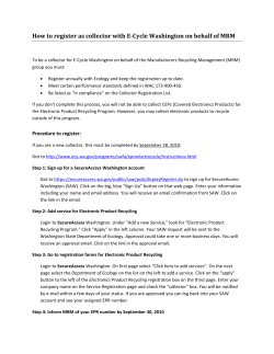


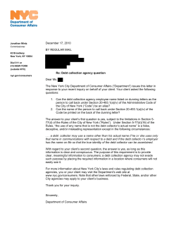
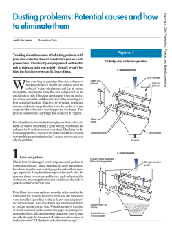

© Copyright 2026