
REAL-WORLD EXHAUST EMISSIONS FROM MODERN DIESEL CARS
WHITE PAPER OCTOBER 2014 REAL-WORLD EXHAUST EMISSIONS FROM MODERN DIESEL CARS A META-ANALYSIS OF PEMS EMISSIONS DATA FROM EU (EURO 6) AND US (TIER 2 BIN 5/ULEV II) DIESEL PASSENGER CARS. PART 1: AGGREGATED RESULTS AUTHORS: Vicente Franco, Francisco Posada Sánchez, John German, and Peter Mock www.theicct.org [email protected] BE I J I N G | BERLIN | B R USS E LS | SAN FRANCIS CO | WAS H INGTO N ACKNOWLEDGMENTS The authors would like to thank all internal and external reviewers of this report for their guidance and constructive comments, as well as the organizations that kindly provided the on-road emissions data. For additional information: International Council on Clean Transportation Europe Neue Promenade 6, 10178 Berlin +49 (30) 847129-102 [email protected] www.theicct.org © 2014 International Council on Clean Transportation Funding for this work was generously provided by the Hewlett Foundation. ABOUT THIS DOCUMENT Our “Real-World Exhaust Emissions from Modern Diesel Cars” report has been divided into two parts. The present document (Part 1: Aggregated results), which can be read as a standalone, introduces the study and presents the aggregated results of our assessment (i.e., at vehicle or vehicle class level). It is intended to appeal to a broad public that includes vehicle emission scientists and policymakers in the field of vehicle emissions. The second part of this report (Part 2: Detailed results [Franco, Posada Sánchez, German, & Mock, 2014]) is aimed at vehicle emission scientists who wish to take a closer look at the on-road emission performance of the vehicles under study. It supplements the results presented in Part 1 by presenting the measured data with a higher level of granularity, using a series of standard data tables and graphical representations of the results that are repeated for each one of the PEMS trips covered in the meta-analysis. This second part also includes explanations on how to read and interpret the detailed charts. i ICCT WHITE PAPER EXECUTIVE SUMMARY This report presents the general assessment of the on-road emission behavior of several different modern diesel passenger cars tested in Europe and in the US using portable emissions measurement systems (PEMS). The level of detail of the analysis and the large number of vehicles (15) and trips covered in the assessment (97, for a total of more than 140 hours and 6,400 kilometers driven) make this the most comprehensive report on the on-road behavior of the latest generation of diesel passenger cars published to date. The data for US vehicles come from a measurement campaign sponsored by the ICCT (and whose results were previously reported in Thompson, Carder, Besch, Thiruvengadam, & Kappana, 2014). The European vehicle data were generously provided by third parties, all but one of which are stakeholders in the European Commission’s working group in charge of amending the Euro 6 regulations to include real-driving emissions testing as a part of the type-approval process of light-duty vehicles in the EU, the Real Driving Emissions of Light-Duty Vehicles (RDE-LDV) group. The raw experimental results were processed using a consistent data preprocessing, analysis, and reporting framework presented for the first time in this report. This framework allows for a clear visualization of the general behavior of individual vehicles over single trips or collections of trips, as well as a detailed assessment of the operating conditions that lead to high-emission events. The main findings of the assessment are consistent with the existing body of evidence indicating that modern diesel passenger cars have low on-road emissions of carbon monoxide (CO) and total hydrocarbons (THC), but an unsatisfactory real-world emission profile of nitrogen oxides (NOX). Particulate matter (PM) and particle number (PN) measurements were absent from most of the datasets and are therefore excluded from this report. This report presents strong evidence of a real-world NOx compliance issue for recenttechnology diesel passenger cars, both for the EU and US test vehicles. The high temporal and spatial resolution of PEMS datasets was used to link the elevated NOx mass emission rates to the driving conditions that cause them. It was found that a sizable share of NOx emissions over individual test trips (typically lasting about one hour) were concentrated over a number of discrete emission spikes spanning a few seconds. These emission events, which varied in frequency from vehicle to vehicle, could not be attributed to “extreme” or “untypical” driving in most cases. Instead, they were due to transient increases in engine load that constitute real-world driving (e.g., uphill driving, acceleration on a ramp, or positive accelerations from a standstill), or to regeneration events that are part of the normal operation of diesel exhaust aftertreatment systems. The average, on-road emission levels of NOX were estimated at 7 times the certified emission limit for Euro 6 vehicles. There were, however, some remarkable differences among the performance of all the vehicles tested, with a few vehicles performing substantially better than the others (Figure 1). This supports the notion that the technologies for “real-world clean” diesels (i.e., vehicles whose average emission levels lie below Euro 6 emission limits under real-world driving) already exist. Policies are needed to ensure that manufacturers will use these technologies and calibrate them to effectively control emissions over the large majority of in-use operating conditions, not just those covered by the test cycle. ii REAL-WORLD EXHAUST EMISSIONS FROM MODERN DIESEL CARS On-road emission results, by vehicle Above type−approval Below or equal to type−approval Above Euro 5 limit Above Euro 6, below Euro 5 limit Below Euro 6 limit Euro 5 limit Euro 6 limit 2 LNT H Average NOX [g/km] SCR L 1.5 SCR F 1 SCR E 0.5 0 M EGR SCR A SCR I EGR SCR N K EGR G J B SCR SCR D EGR C SCR EGR O 100 120 140 160 180 Average CO2 (as % of type−approval [g/km]) 15 test vehicles in total (6 manufacturers), with different NOX control technologies: • 10 selective catalytic reduction (SCR) • 4 exhaust gas recirculation (EGR) • 1 lean NOX trap (LNT) Average Euro 6 NOX conformity factors (ratio of on-road emissions to legal limits): • all cars: 7.1 • best performer (Vehicle C, SCR): 1.0 • bad performer (Vehicle H, LNT): 24.3 • worst performer (Vehicle L, SCR): 25.4 Figure 1: Overview of on-road NOX and CO2 emission results for all vehicles under test Unless the appropriate technical measures are adopted, the high on-road emissions of NOX from the new diesel technology classes of passenger cars could have serious adverse health effects on the exposed population. Regulatory action is urgently required in Europe, where all new diesel passenger cars sold from September 2014 belong to the Euro 6 class and the regional share of diesel vehicles in the passenger car fleet is higher than anywhere else in the world. In this sense, the European RDE-LDV initiative (Weiss, Bonnel, Hummel, & Steininger, 2013) requiring the inclusion of on-road testing with PEMS as part of the passenger car type-approval process in the EU is a step in the right direction. However, the existence of the real-world diesel NOX issue must be acknowledged by regulators in its full extent and subsequently addressed in collaboration with vehicle manufacturers and other stakeholders. Keywords: Diesel cars, real-world emissions, PEMS, air quality, NOX, fuel consumption, Euro 6, Tier 2 Bin 5, NEDC, FTP, RDE-LDV, type-approval iii ICCT WHITE PAPER TABLE OF CONTENTS About This Document................................................................................................................. i Executive Summary.................................................................................................................... ii Abbreviations...............................................................................................................................1 1 Introduction............................................................................................................................. 2 2 Background.............................................................................................................................4 2.1 The real-world emissions problem............................................................................................. 4 2.2 On-board emission measurements............................................................................................ 4 2.3 Technologies for Euro 6 diesel compliance............................................................................ 6 2.3.1 In-cylinder control................................................................................................................. 7 2.3.2 Exhaust gas recirculation (EGR)..................................................................................... 7 2.3.3 Selective catalytic reduction (SCR)............................................................................... 7 2.3.4 Lean NOX traps (LNTs)......................................................................................................... 8 3 Data sources.......................................................................................................................... 10 3.1 About the test vehicles...................................................................................................................11 3.2 About test route compositions and driving styles..............................................................12 4 Data analysis..........................................................................................................................13 4.1 Key principles ...................................................................................................................................13 4.2 Distance-specific emission factors...........................................................................................14 4.2.1 Raw average emission factors........................................................................................14 4.2.2 Situation-specific emission factors...............................................................................14 4.3 CO2 window analysis......................................................................................................................17 4.3.1 CO2 normalization.................................................................................................................18 4.4 Instantaneous emissions analysis............................................................................................ 20 5 Results and discussion.........................................................................................................22 5.1 Results.................................................................................................................................................22 5.1.1 Raw distance-specific emissions for all vehicles......................................................22 5.1.2 Characterization of the PEMS trips...............................................................................24 5.1.3 NOX emission factors by driving situation................................................................. 30 5.1.4 Windowed emission results.............................................................................................36 5.2 Discussion......................................................................................................................................... 46 5.2.1 PEMS, Euro 6 and the future of passenger car emissions regulations.......... 46 5.2.2 Raw average emission factors........................................................................................47 5.2.3 Situation-specific emission factors and windowed analysis............................. 48 5.2.4 Real-driving emissions and (real) clean diesel cars.............................................. 49 6 Conclusions and recommendations...................................................................................51 7 References.............................................................................................................................52 iv REAL-WORLD EXHAUST EMISSIONS FROM MODERN DIESEL CARS ABBREVIATIONS CF Conformity factor CO Carbon monoxide CO2 Carbon dioxide DPF Diesel particulate filter EC European Commission EC-JRC European Commission—Joint Research Centre EF Emission factor EGR Exhaust gas recirculation EU European Union FTP Federal test procedure g/km Grams per kilometer g/min Grams per minute GPS Global positioning system HDV Heavy-duty vehicle HVAC Heating, ventilation and air conditioning HzHertz IDIdentifier kgkilogram kmkilometer LNT Lean NOX trap mg/km milligrams per kilometer mg/mi milligrams per mile NEDC New European driving cycle NH3Ammonia NOX Nitrogen oxides NTE Not to exceed OBD On-board diagnostics PEMS Portable emissions measurement system PN Particle number RDE-LDV Real driving emissions from light-duty vehicles SCR Selective catalytic reduction THC Total hydrocarbons ULEV Ultra-low-emission vehicle US United States of America 1 ICCT WHITE PAPER 1 INTRODUCTION Diesel passenger cars have become very popular in Europe over the past two decades. Many European customers have favored them in spite of their higher purchase price because diesel fuel has been historically cheaper than gasoline in Europe. Diesel cars are typically more fuel-efficient than their gasoline counterparts, and they are also broadly perceived as being more durable and reliable. Over the past years, the improved availability and quality of diesel fuel has also sparked interest in diesel cars in the US. Strong demand from the domestic market has turned European manufacturers into global leaders in diesel passenger car technology. The dieselization of the European car fleet has made a positive contribution to meeting regional CO2 targets (Fontaras & Samaras, 2007), and the newest Euro 6 diesel cars meet stringent emission limits for regulated pollutants (CO, NOX, particle mass and number, and total hydrocarbons). However, as explained in Section 2 of this report, these emission limits are evaluated with a standard test performed under predefined conditions in a chassis dynamometer laboratory (Franco et al., 2013). There is substantial evidence that the actual, on-road emissions may not be sufficiently controlled under certain operating conditions that are not covered by the laboratory test. As a result, and contrary to expectations, real-world emission levels of NOX have been reported to increase with the introduction of the Euro 5 and Euro 6 technology classes (Chen & Borken-Kleefeld, 2014; Fontaras, Franco, Dilara, Martini, & Manfredi, 2013; Ligterink, Kadijk, van Mensch, Hausberger, & Rexeis, 2013; Weiss et al., 2011). In some cases, the measured NOX emission rates for the more demanding driving conditions not covered by the type-approval cycle were several times higher than the relevant emission limits. The previous studies were limited to a handful of vehicles, and they provided inconclusive evidence of a widespread on-road compliance problem. However, the results prompted research efforts by the ICCT and other research partners to gather emissions data from additional vehicles. This report compiles the on-road emissions datasets gathered from different measurement campaigns that made use of on-board exhaust gas analyzers (i.e., PEMS) and analyzes the real-world emission profile of current technology diesel passenger cars sold in the EU and US markets. The measurement campaigns—briefly described in Section 3—were carried out in the EU and US by the ICCT and other research partners who generously shared their data to support our meta-study. More than 140 hours worth of second-by-second data were collected from several sources covering a combined total of more than 6,400 km driven for 15 test vehicles. This makes our meta-study the most comprehensive of its kind published to date. The results presented in this report provide a sound experimental basis for the statistical characterization of the emission profile of the latest diesel passenger cars. In our view, they are also robust enough to justify more stringent regulations to control emissions from these vehicles. Due to the heterogeneous origin of the data, and in order to facilitate the comparisons across different measurement campaigns, vehicles, and testing conditions, we developed a consistent framework for the analysis and reporting of the results. This allowed us to characterize the general behavior of the vehicles and to identify the operating conditions that lead to high emissions. The most significant product of this framework (described in Section 4) is a series of standard PEMS charts and summary tables that can be produced for individual PEMS trips or collections of trips, allowing us to compare 2 REAL-WORLD EXHAUST EMISSIONS FROM MODERN DIESEL CARS the on-road emissions of regulated pollutants of the test cars to the relevant legal emission limits and corresponding type-approval results, and to visualize the operating conditions that lead to elevated instantaneous emissions. The high-level results of our analysis are provided in Section 5 of this document, along with discussion of current efforts to include PEMS testing as part of the type-approval process for Euro 6 passenger cars in Europe (Weiss et al., 2013). The second part of this report, featuring the complete collection of standard PEMS charts for all the trips covered in the report, can be downloaded from ICCT’s website. 3 ICCT WHITE PAPER 2 BACKGROUND In this section, we briefly introduce the “real-world” emissions problem affecting current passenger cars—i.e., the discrepancy between certified emission levels from laboratory testing and actual, on-road emissions under realistic driving conditions—with special attention to NOX emissions from diesel passenger cars. We also give an overview of the regulatory landscape for diesel passenger cars in the EU and US, of the main NOX aftertreatment technologies used in modern diesel passenger cars, and of the on-road emissions measurement technique used in the experimental campaigns covered in this report (PEMS). 2.1 THE REAL-WORLD EMISSIONS PROBLEM Standards are in place to control the emissions of passenger cars worldwide. Most regions have established enforceable emission limits for CO2 (which is directly linked to fuel efficiency) and for other pollutants with adverse health effects, typically CO, NOX, PM, and THC. These emission limits are linked to a standardized chassis dynamometer test cycle, which is a predetermined time-speed profile that the vehicle under test has to follow in an emissions laboratory while its exhaust emissions are measured. Standard emissions certification tests are carried out as part of regulated vehicle typeapproval processes. Ideally, the driving cycle and other aspects of the test procedure will have been laid out in such a way that they provide a realistic approximation of the actual conditions vehicles encounter on the road. However, this is not always possible because the emission tests must have narrow boundary conditions to ensure that results from different vehicles can be directly compared, and that all vehicles sold in a given market are held to the same standards. This situation has led to vehicle emissions being certified through laboratory procedures that cannot capture the whole range of operating conditions vehicles encounter during real use. At the same time, the increased levels of stringency (e.g., NOX emission limits for diesel passenger cars on the basis of the NEDC driving cycle were reduced by 68% from Euro 4 to Euro 6) and the lack of updates to the type-approval procedures in some jurisdictions have encouraged engineering strategies that ensure good fuel efficiency and compliance with the relevant emission limits—as long as the vehicles are operated within the narrow boundary conditions of the standardized test, but not necessarily during normal use. 2.2 ON-BOARD EMISSION MEASUREMENTS Vehicle emissions are typically tested in laboratories equipped with a chassis dynamometer. During chassis dynamometer testing, the vehicle under test remains stationary on a set of rollers that simulate driving resistance, and its emissions are collected and analyzed as it is driven according to a standard time/velocity profile known as the driving cycle. Measuring emissions under controlled conditions in a laboratory increases the repeatability and the comparability of results, which makes this an excellent approach for vehicle type-approval tests. However, it is also an artificial way of measuring emissions, and its results may differ from the actual on-road emissions1 because it eliminates several factors that influence emissions (e.g., road gradient, hard accelerations, use of air conditioning, and traffic or weather conditions). 1 ICCT has investigated the discrepancy between laboratory and on-road fuel consumption figures for passenger cars in Europe and the US (Mock et al., 2013). 4 REAL-WORLD EXHAUST EMISSIONS FROM MODERN DIESEL CARS Vehicle emissions of individual vehicles can also be measured with so-called real-world techniques such as remote sensing (Bishop, Starkey, Ihlenfeldt, Williams, & Stedman, 1989) and PEMS, (Vojtíšek-Lom & Cobb, 1997). The data reported in this document were collected using PEMS, which are complete sets of emission measurement instruments that can be carried on board the vehicle to record instantaneous emission rates of selected pollutants with good levels of accuracy. A PEMS unit usually comprises a set of gas analyzers with sample lines (some of which may be heated) directly connected to the tailpipe, plus an engine diagnostics scanner designed to connect with the on-board diagnostics (OBD) link of the vehicle (Figure 2). Figure 2: Passenger car instrumented with PEMS2 PEMS is a relatively new technology that has experienced remarkable development over the past two decades, with improved gas measurement principles and significant reductions in size, weight, and overall complexity. PEMS are relatively simple and inexpensive to purchase and maintain in comparison to a full dynamometer test cell, and they have thus become a popular tool for scientific studies. In recent years, they have also been applied for regulatory purposes. US authorities have introduced additional emissions requirements based upon PEMS testing and the “not to exceed” (NTE) concept, whereby emissions averaged over a time window must not exceed specified values for regulated pollutants while the engine is operating within a control area under the torque curve (US EPA, 2005). In Europe, PEMS are being used to verify the in-service conformity of Euro V and Euro VI heavy-duty vehicles with the applicable emissions standards (EC, 2011, 2012), and the EC is working with stakeholders in the Real Driving Emissions from LightDuty Vehicles group (RDE-LDV) to include PEMS testing as part of the type-approval process of Euro 6 passenger cars (Weiss et al., 2013). PEMS typically measure instantaneous raw exhaust emissions of CO2, CO, NOX, and THC. Portable particle mass analyzers have recently become commercially available after 2 Photo credit: European Commission—Joint Research Centre (EC-JRC). 5 ICCT WHITE PAPER extensive testing (Mamakos et al., 2011), and portable particle number (PN) analyzers are now reaching the market in anticipation of their application to RDE measurements. Still, the range of pollutants that can be measured with PEMS is limited in comparison to laboratory measurements. Other limitations of PEMS include the added mass (of approximately 30 to 70 kg, and up to 150 kg if several pollutants are simultaneously measured) that may bias the measurement, and the reduced repeatability due to real-world sources of variability (e.g., traffic or weather conditions). 2.3 TECHNOLOGIES FOR EURO 6 DIESEL COMPLIANCE The Euro 6 standard entered into force on September 1, 2014, for the type approval of new types of cars in the EU. From January 2015, it will apply to the registration and sale of all new cars. One of the biggest technological challenges of the transition from Euro 5 to Euro 6 for diesel passenger cars is the achievement of the required 66% reduction of NOX emissions over the New European Driving Cycle (NEDC; see Table 1). Table 1: Applicable Euro 5 and Euro 6 emission limits for diesel passenger cars Diesel emission limits [mg/km over NEDC cycle] CO NOX PM THC+NOX PN [#/km over NEDC cycle] Euro 5a 500 180 5.0 230 – Euro 5b/b+ 500 180 4.5 230 6.0E11 Euro 6b/6c 500 80 4.5 170 6.0E11 Pollutant Aftertreatment NOX control for Euro 6 light-duty vehicles is based primarily on two technologies: lean NOX traps (LNTs) and selective catalytic reduction (SCR). These technologies can be applied in combination with exhaust gas recirculation (EGR, which has been applied since the adoption of Euro 2 in the 1990s) or with in-cylinder control strategies (e.g., fuel injection delay and other combustion improvements that reduce the need for aftertreatment systems). LNTs, currently used in light-duty diesel vehicles in the US and Europe, have shown good durability and NOX reduction performance during chassis dynamometer testing, in which they match the performance levels of SCR systems (Johnson, 2009). The advantages of an LNT compared with an SCR system are that it is generally more economical for engines with displacements of less than 2.0 liters (Posada, Bandivadekar, & German, 2013). LNTs are also likely more acceptable to customers because they do not require periodic refilling with urea, although LNT operation has a small impact on fuel consumption (Johnson, 2009). The advantages of SCR are that it is generally more economical for engine above 2.0 liters and it can provide better fuel economy and CO2 emissions through engine tuning for low PM and high engine-out NOX emissions. The specific technology selected by manufacturers (SCR or LNT) depends not only on emission standards, but also on fuel economy strategies that are covered under CO2 emission standards. Manufacturers will likely choose the NOX aftertreatment technology based on a combination of factors that include cost, technical complexity, reliability, fuel economy, and consumer acceptance. 6 REAL-WORLD EXHAUST EMISSIONS FROM MODERN DIESEL CARS In the sections that follow, the technologies used to achieve Euro 6 diesel compliance (i.e., below or equal to 80 mg/km over NEDC) are briefly discussed. These include SCR and LNT, as well as EGR and in-cylinder control strategies. 2.3.1 In-cylinder control Current combustion engine design technology makes it possible to achieve Euro 6 levels for NOX with in-cylinder control strategies, i.e., adjusting the combustion process to keep engine-out emissions at a sufficiently low level. Low NOX emissions can be accomplished through a combination of aggressive EGR (see Section 2.3.2), compression ratio reduction, use of two-stage turbocharging, variable valve lift, combustion chamber reshaping, and a reduction of fuel injection pressure (Terazawa, Nakai, Kataoka, & Sakono, 2011). A shortcoming of relying solely on in-cylinder control strategies to control NOX is related to high-load operation. Engine-out NOX emissions are known to rise sharply with increased engine loads, while some type-approval test cycles, such as the NEDC, do not include high-load events. This means that a vehicle without specific NOX aftertreatment could be type-approved to a very stringent NOX emission standard and yet have an unsatisfactory emission behavior during higher-load in-use operation (e.g., during acceleration periods or higher speeds). 2.3.2 Exhaust gas recirculation (EGR) EGR systems work by routing a portion (controlled by the EGR valve) of engine-out exhaust gas back to the intake manifold. Since exhaust gas has a lower oxygen content than intake air, the effect of EGR is to lower the oxygen content in the cylinder, which leads to a cooler combustion process and a lower level of NOX formation. Some EGR systems incorporate a heat exchanger to further cool the exhaust gas before recirculation. EGR is a proven technology that became widespread after the introduction of Euro 4 and Euro 5 regulations in Europe, and it is used for both gasoline and diesel engines (with the latter being able to apply EGR at rates above 60% under some operating conditions). A disadvantage of EGR is that the maximum exhaust recirculation rate that can be applied while maintaining stable combustion decreases with engine load (Zheng, Reader, & Hawley, 2004). Therefore, it primarily reduces NOX formation during low load operation, and not during real-world high-load events. 2.3.3 Selective catalytic reduction (SCR) SCR is an exhaust aftertreatment technology that uses a catalyst to chemically break down NOX. This requires the injection of variable amounts of an external reducing agent, which is stored in a separate tank that needs to be periodically refilled. Most SCR systems use an aqueous urea solution (sometimes referred to as diesel exhaust fluid) for this purpose. Urea vaporizes in the exhaust to yield CO2 and ammonia (NH3). NOX emissions in the exhaust gas react with the NH3 in the catalyst to yield gaseous nitrogen (N2) and water. SCR technology has been deployed in HDVs since the adoption of Euro IV. Although there have been substantial advances in SCR technology for light-duty applications, SCR systems in passenger cars face similar challenges as in HDV applications. These challenges are related to low-temperature operation during cold start and urban driving conditions, as well as precisely matching urea injection with NOX emissions (Johnson, 2014). 7 ICCT WHITE PAPER The effectiveness of an SCR system in reducing NOX emissions is dependent on a host of design parameters, including catalyst material, catalyst volume, urea dosing/control strategy, and physical system layout. It is also temperature-dependent: Below some threshold for exhaust temperature, the injected urea cannot be converted to NH3. At low exhaust temperatures, catalyst activity also falls sharply. Urban driving is typically characterized by low-speed, stop-and-go conditions, which put a relatively low average load on a vehicle’s engine. Exhaust temperature generally varies with engine load, and diesel exhaust temperatures are lower than those of gasoline exhaust. At idle, diesel exhaust temperature can be as low as 100°C, increasing to more than 500°C as load approaches its peak. Various aspects of system design affect the operating temperature thresholds of SCR, but the primary factor is the use of vanadiumbased catalysts in virtually all European SCR systems. While vanadium-based catalysts offer some advantages (low cost, good sulfur tolerance), they have relatively poor low-temperature performance relative to other catalyst options. The low-temperature activity of vanadium catalysts can be improved by optimizing the ratio of NO to NO2 in the exhaust using an oxidation catalyst ahead of the SCR catalyst. Alternatively, copperzeolite catalysts with greater low-temperature activity can be used, but these are more expensive and more sensitive to the presence of sulfur in the fuel. The performance of SCR systems can be improved with thermal management to increase exhaust temperatures (Bergmann, 2013). Start-stop systems are also effective at keeping the SCR system warm by avoiding the cooler exhaust temperature of idling conditions. Low-temperature catalyst activity can be improved by increasing catalyst volume, regardless of catalyst material, or by optimizing ammonia storage in the catalyst via different dosing strategies. The latter strategy, however, may increase tailpipe NH3 emissions (“ammonia slip”) in the absence of an effective ammonia slip catalyst downstream of the SCR catalyst (Lowell & Kamakaté, 2012). Further technical details on current SCR systems for diesel passenger cars can be found in Braun et al., 2014. 2.3.4 Lean NOX traps (LNTs) Lean NOX traps combine oxidation and reduction catalysts with an NOX adsorber that chemically binds and stores NOX under lean-burn conditions (i.e., when engines operate with an excess of air with respect to the stoichiometric air to fuel ratio). Some applications use the oxidation catalyst to convert NO to NO2 and store it as nitrate on the alkaline earth oxide washcoat. When the NOX trap is saturated, it needs to be regenerated by switching engine operation to stoichiometric or fuel-rich (i.e., with an excess of fuel) for a few seconds. This causes the stored NOX to be desorbed and subsequently reduced to N2 and O2 in the reduction catalyst (e.g., a conventional three-way catalyst) downstream of the adsorber. Unlike SCR systems, LNTs do not require an external reducing agent, and they are also generally lighter and more compact than SCRs. However, the periodical regeneration of the trap imposes a small fuel penalty. NOX adsorbers also adsorb sulfur oxides and therefore require ultra-low sulfur content (below 15 ppm) in the diesel fuel. Also, since sulfur oxides are more difficult to desorb than NOX, LNTs need to run periodical desulfation regeneration cycles to remove them. Two of the most challenging aspects of LNT integration in a vehicle are establishing engine operating conditions for adequate NOX reduction while minimizing fuel consumption, and dealing with cold start conditions. Typical fuel penalties are in the order of 8 REAL-WORLD EXHAUST EMISSIONS FROM MODERN DIESEL CARS 2–4% (Majewski, 2007). Reducing light-off temperatures during cold starts can be accomplished through thermal management, or with delayed injection during start-up periods. Another problem with LNTs is that the NOX storage capacity of the catalyst is fixed. This means that, as engine load increases, the frequency of trap regeneration events also needs to increase, and this carries additional fuel penalties. 9 ICCT WHITE PAPER 3 DATA SOURCES The data presented in this report cover a total of 15 vehicles. The vehicles were anonymized3 and designated with letter codes (A to O; see Table 2). Individual PEMS trips were assigned a unique ID using the letter code of the vehicle followed by consecutive numbering. This naming convention is used for Part 2 of this report. The emissions data were collected during different measurement campaigns carried out by different institutions. »» One of these campaigns—which was commissioned to West Virginia University (WVU) by the ICCT—was carried out in the US with US-spec vehicles certified to the US Tier 2 Bin 5/California LEV II standard. The technical details of this campaign (which covered Vehicles B, F and H in Table 2) have been reported in detail elsewhere (Thompson et al., 2014). »» The PEMS trip data for Vehicles C, J, K, L, M and N (all Euro 6 vehicles) were purchased by the ICCT from Emissions Analytics, a UK-based emissions consultancy with vast experience in PEMS testing. Only one trip was available for each vehicle, all following the same route. »» The rest of the datasets (covering Vehicles A, D, E, G, I and O) were gathered from stakeholders of the RDE group that generously contributed to this work. All these tests were carried out on Euro 6 passenger cars. The data contributors did not include vehicle manufacturers or environmental NGOs. 3 Some vehicles were anonymized to comply with requests from third-party data contributors. Ultimately, all the vehicles in the meta-study were anonymized to avoid an uneven treatment of vehicle manufacturers. This decision, which is contrary to the ICCT’s usual practice, also affected the vehicles analyzed in Thompson et al., 2014. 10 REAL-WORLD EXHAUST EMISSIONS FROM MODERN DIESEL CARS Table 2 Overview of vehicles included in the analysis ID Body type NOX control Emission standard Total trips Data source Make Starting mileage [km] A SUV SCR+LNT Euro 6b 6 Anonymous 1 M1 22,900 B SUV SCR Tier 2 Bin 5/ ULEV II 8 WVU/ICCT M1 24,200 C Sedan SCR Euro 6 1 Emissions Analytics M1 4,900 D Station wagon SCR Euro 6 25 Anonymous 2 M2 22,000 E Sedan SCR Euro 6 9 Anonymous 3 M2 N/A F Sedan SCR Tier 2 Bin 5/ ULEV II 15 WVU/ICCT M2 24,500 G Sedan SCR Euro 6b 6 Anonymous 1 M2 13,500 H Sedan LNT Tier 2 Bin 5/ ULEV II 13 WVU/ICCT M2 7,600 I Sedan EGR + in-cylinder Euro 6 4 Anonymous 2 M3 7,600 J Station wagon EGR + in-cylinder Euro 6 1 Emissions Analytics M3 200 K Sedan EGR + in-cylinder Euro 6 1 Emissions Analytics M3 1,600 L Luxury sedan SCR Euro 6 1 Emissions Analytics M4 1,400 M Minivan SCR Euro 6 1 Emissions Analytics M5 3,500 N Sedan SCR Euro 6 1 Emissions Analytics M6 1,500 O Hatchback Dual EGR Euro 6b 5 Anonymous 1 M6 11,000 3.1 ABOUT THE TEST VEHICLES An ideal selection of test vehicles would have covered as many manufacturers, models, and aftertreatment technologies as possible. It should have also been done independently from manufacturers (e.g., by renting the vehicles to perform the tests). However, with the exception of the US testing (where these principles were followed), the selection of the test vehicles was performed without the intervention of the ICCT. This circumstance, coupled with the low availability of Euro 6 vehicles in the market, has led to an uneven coverage of makes and models in the test vehicle lineup. In total, 15 vehicles from six manufacturers were tested. Most of the trips were by vehicles equipped with SCR technology for the aftertreatment of NOX emissions. Four vehicles (three of them from the same manufacturer) had no specific NOX aftertreatment system, and only one of our test vehicles (Vehicle H) was equipped with a single LNT. Below are a few further remarks on the final composition of the test vehicle selection: »» Vehicle D was a pre-series vehicles furnished by the corresponding manufacturer. This may have had implications in the emission levels observed for this vehicle (see discussion in Section 5.2). 11 ICCT WHITE PAPER »» Vehicles D, E and G are the same make and model, as is Vehicle F (but the latter is the US-spec vehicle instead of the EU model). »» Vehicles A and B are also the same make and model; A is the EU-spec vehicle and B is the vehicle for the US market. Their NOX aftertreatment systems differ slightly. The EU vehicle incorporates an LNT in combination with an SCR system, while the US vehicle used only an SCR system. »» Vehicles I and J are the same make, model, and engine type; Vehicle K is the same make and model as Vehicles I and J, but it had a higher-powered engine (and a sweet stereo system). »» The ICCT purchased the data for Vehicles C, J, K, L, M, and N. These measurements were initially performed by Emissions Analytics independently from the ICCT and for a purpose unrelated to this report. 3.2 ABOUT TEST ROUTE COMPOSITIONS AND DRIVING STYLES The PEMS trips analyzed in this report come from several different testing campaigns. The cars were therefore driven on different routes, and the relative shares of urban/ rural/motorway driving, road gradients, and driving styles all differed as well. In some cases, the vehicles were driven repeatedly over the same route or collection of routes. For some vehicles, only a single PEMS trip is available for analysis. This heterogeneity has some disadvantages, because it makes the comparisons of trip averages less meaningful (as they may be distorted by the aforementioned sources of on-road variability). However, a wide variability of driving conditions also has the advantage of allowing us to identify the factors that lead to high (and low) levels of on-road emissions, provided that the data are properly analyzed. The emissions data analysis techniques that we applied in this work (described in Section 4) allowed us to report the measured emission levels not just as trip averages, but also as a function of several driving situations pertinent to the route composition and the driving style. Furthermore, a detailed characterization of the individual PEMS trips can be found in Part 2 of this report. 12 REAL-WORLD EXHAUST EMISSIONS FROM MODERN DIESEL CARS 4 DATA ANALYSIS The analysis was performed according to a consistent framework for data preprocessing, analysis and reporting that is presented for the first time in this report. This framework allows for a clear visualization of the general behavior of individual vehicles over single trips or collection of trips, as well as a detailed assessment of the operating conditions that lead to high-emission events. It also makes it possible (with the limitations inherent to the differences in instrumentation, route selection, and driving conditions) to compare emission levels from different datasets. The data preprocessing, analysis, and reporting was done in a semiautomatic manner through a set of Matlab scripts developed by the ICCT, which were also used to produce the charts in this report. In the following sections, we will describe the most relevant aspects of this methodological framework for the treatment of PEMS data. This background information should help with the interpretation of the results provided in Section 5, as well as the collection of PEMS charts presented in Part 2 of this report. 4.1 KEY PRINCIPLES The key principles of the analysis are as follows: »» No data exclusions. All of the measured emissions data available for each trip were included in the analysis, and they are initially reported without exclusions. This means, for example, that cold starts or DPF regeneration events were not treated separately. This helps ensure that the real-world emission levels reported are not influenced by the arbitrary removal of certain sections where the driving conditions are deemed “untypical.” For each trip, the emissions were also evaluated after the application of two different sets of dynamic boundary conditions that exclude the more demanding driving conditions4 (called "Undemanding driving 1" and "Undemanding driving 2"; see section 4.2.2). »» Emissions in context. Whenever appropriate, the measured emission levels are compared with the relevant Euro 5 and Euro 6 emission limits,5 or with the typeapproval CO2 values of the vehicles under test. The operating conditions of the vehicle during the trip (velocity, acceleration, road gradient, and exhaust temperature) are also linked to differences in the emission levels. For the purpose of this report, we will refer to this aspect of the analysis as “on-road compliance,” even though strictly speaking there is no legal obligation for vehicles to comply with the emission limits for regulated pollutants once they have passed the type-approval test.6 »» Multiple detail levels. PEMS charts exist for different levels of data aggregations: from vehicle and trip averages to instantaneous, second-by-second emissions. When appropriate, emission signals are windowed (see Section 4.3) to optimize the amount of information extracted from the PEMS datasets. »» Consistent visualization of results. A consistent color scheme is used throughout the different charts and tables used to present the results in both parts of this report. 4 The emission levels resulting from this analysis are only representative of the mild driving conditions that they cover, and they should not be construed as the ICCT’s definition of what constitutes normal driving. 5 The legal Euro 5 and Euro 6 limits are provided only for reference, as they apply solely to the NEDC chassis dynamometer driving cycle. 6 The emission levels of the three Tier 2 Bin 5/ULEV II vehicles are also compared to the legal Euro 5 and Euro 6 emission limits, even though these do not apply to them. The type-approval results considered for these vehicles refer to the FTP (Federal Test Procedure) cycle, which is the regulated cycle in the US. 13 ICCT WHITE PAPER This improves the readability of complex charts and guides the reader through the different levels of detail. »» Transparency. All the relevant emission signals are reported. Detailed results for all trips are provided in Part 2 of this report, both in graphic and tabular form. 4.2 DISTANCE-SPECIFIC EMISSION FACTORS The majority of the emission factors reported in our analysis are distance-specific (or “distance-based”), meaning that they are given in terms of mass of pollutant emitted per distance driven. This is the usual way in which legal emission limits are expressed.7 4.2.1 Raw average emission factors Distance-specific emission factors can be easily derived by dividing the cumulative emissions of a pollutant (measured by the PEMS system) by the total distance covered (which is in turn derived from the GPS velocity signal). This can be done for individual PEMS trips, or for a collection of several PEMS trips from the same vehicle. If no data exclusions are performed, thus derived “raw” (all-inclusive) emission factors are representative only of the driving conditions that produced them. Unlike emission factors derived from repeatable chassis dynamometer tests, these emission factors will exhibit substantial variability because they are affected by the trip composition (e.g., the share of urban or highway driving), the thermal history of the engine and aftertreatment system (i.e., whether the vehicle was cold- or warm-started), environmental conditions (e.g., temperature, ambient pressure, rain, altitude, or road gradient), traffic conditions, and other uncontrolled sources of variability. As a general rule, on-road emission factors will be higher than those derived from chassis dynamometer experiments, because most on-road sources of emission variability tend to push emission levels upward.8 The key issue is whether measured on-road emissions levels stay reasonably close to the laboratory-based values. A usual way of comparing on-road emission levels to laboratory-based emission limits is to calculate the so-called conformity factor (CF), which is the ratio of (distance-specific) on-road emissions to a reference (also distance-specific) emission limit. For the purposes of this report, we will compute the CF of measured emissions to Euro 6 emission limits. 4.2.2 Situation-specific emission factors One of the main advantages of PEMS testing is the ability to assess the influence that real-world factors have upon emissions. The usual way of doing this is to design test campaigns in such a way that a certain real-world influencing factor is assessed in a “one-at-a-time” fashion. For example, one can plan a certain route to include a large share of uphill driving, or instruct the driver to drive the same route several times with more or less aggressive behavior, and evaluate the resulting impact of these qualitative variations upon emission levels. 7 Note that the distance in legal emission limits refers to the fixed distance of the driving cycle, whereas for PEMS it is the (variable) trip or data window distance that serves as the basis for the calculation of the emission factors. 8 An exception to this is the influence of cold-start emissions, because most regulated cycles are shorter than the typical PEMS trip (which usually lasts about an hour). Therefore, the relative impact of cold-start emissions on the average emission factors derived for a PEMS trip is lower than, for example, the contribution of cold-start emissions to type-approval results over NEDC. 14 REAL-WORLD EXHAUST EMISSIONS FROM MODERN DIESEL CARS Average EF [g/km] This approach was not possible in our study, because the experimental data came from different studies with different experimental designs that were for the most part beyond the control of ICCT. It is, however, possible to filter or “bin” the data according to different criteria and then develop distance-specific emissions that let us assess the impact of different operating conditions. In this report, the emission signals were binned using the signals related to instantaneous velocity and acceleration, estimated road gradient, and measured temperature (either exhaust or coolant temperature, depending on availability). These binning criteria were applied to calculate situation-specific emission factors, which can then be plotted (see, e.g., Figure 3) or listed in tabular form to visualize the effect of real-world factors upon emission rates. NOX CO2 400 1 200 0.5 0 0 Distance Time Type−approval CO2 Average EF [g/km] Euro 5 limit THC CO Euro 6 limit Strong negative a*v (<−9.2 W/kg) 0.5 0 0.02 Mild negative a*v (−9.2 to 0 W/kg) 0.01 Zero or mild positive a*v (0 to 9.2 W/kg) 0 Strong positive a*v (>9.2 W/kg) Figure 3: Example visualization of situation-specific emission factors (binning by acceleration*velocity) The binning criteria used for the derivation of these emission factors are summarized in Table 3 and defined as follows: »» Velocity. The instantaneous velocity provides a very simple and useful characterization of the driving situation. The datasets were filtered using the GPS velocity signal, leading to four velocity bins: Idling (velocity below 2 km/h), Urban (2 to 50 km/h), Rural (50+ to 90 km/h) and Motorway (above 90 km/h). For practical reasons, the Idling section of the trips was defined in terms of vehicle speed instead of actual engine speed, and no distance-specific emission factors were derived for this particular bin.9 »» Acceleration*velocity (a*v). If we multiply the instantaneous GPS velocity signal by the (calculated) instantaneous acceleration, we obtain an a*v signal [in m2/ s3, or W/kg], which is an approximation of instantaneous, mass-specific power. This signal adopts negative values during decelerations. The set point of 9.2 W/kg was selected as the threshold between “mild” and “strong” a*v because this is the maximum value for the NEDC time-velocity trace. »» Road gradient. The road gradient or steepness imposes an additional load on the engine that is proportional to the mass of the vehicle and to the sine of the 9 Instead, idling emission rates were calculated in terms of mass of pollutant emitted per unit of time. 15 ICCT WHITE PAPER gradient angle Θ (this load is negative for downhill driving, when Θ<0). The road gradient [in %] was estimated from the GPS altitude and velocity signals. In order to have a robust calculation of road gradient (i.e., one that is less affected by noise in the input signals), the gradient was initially calculated using moving 500-meter windows. These windowed gradient values were then mapped back (see Part 2 of this report) to 1 Hz to produce a signal that is a smoothed estimator of instantaneous road gradient. »» Exhaust gas/engine coolant temperature. Monitoring temperature signals is useful to determine the thermal history of the engine block and the aftertreatment system. The emissions of NOX are especially sensitive to exhaust temperature because a minimum temperature threshold is required by both SCR and LNT systems to perform adequately, and also because engine-out NOX emissions rise quickly as exhaust temperature increases. »» In addition to the one-at-a-time application of the binning criteria, we also applied them in combination to derive emission factors for two different categories of “undemanding” driving. This was done by excluding the driving situations that would in principle lead to elevated emission levels10 (e.g., high road gradient, strong positive acceleration*velocity). These undemanding emission factors are therefore not representative of real-world driving, but they were nonetheless derived to determine “best behavior” baseline emission levels for the test vehicles under favorable conditions. 10 This is the only instance in which data exclusions were performed for the purposes of our analysis. The amount of data that were excluded from each trip to derive the “undemanding” emission factors is reported in Part 2 of this report. 16 REAL-WORLD EXHAUST EMISSIONS FROM MODERN DIESEL CARS Table 3: Filtering criteria for the derivation of situation-specific emission factors A) Single binning (one criterion at a time) Criterion Velocity [km/h] Acceleration* velocity (a*v) [W/kg] Road gradient [%] Exhaust gas/coolant temperature [°C] Calculation1 From GPS velocity From GPS velocity From GPS velocity and GPS altitude From tailpipe meas./ECU readout Set points for the bins Bin descriptor Color ID Velocity <2 km/h Idling Idle 2 ≤ Velocity < 50 km/h Urban Urb. 50 ≤ Velocity < 90 km/h Rural Rur. Velocity ≥ 90 km/h Motorway Mwy. a*v < -9.2 W/kg Strong negative a*v -9.2 ≤ a*v < 0 W/kg Mild negative a*v 0 ≤ a*v < 9.2 W/kg Zero or mild positive a*v a*v ≥ 9.2 W/kg Strong positive a*v Gradient < -4 % Strong downhill -4 ≤ Gradient < -1 % Mild downhill -1 ≤ Gradient < 1 % Pretty flat 1 ≤ Gradient < 4 % Mild uphill Gradient ≥ 4 % Strong uphill Temperature < 10th percentile for the trip Cold temperature Cold 10th ≤ Temperature < 90th percentile Medium temperature Med. Temperature ≥ 90th percentile for the trip Hot temperature Hot B) Combined filtering (several criteria applied concurrently) Combination Undemanding driving 1 Undemanding driving 2 Filtering Data are binned by velocity. Only points with motorway speed below 120 km/h are included. Likewise, only the points in the “Pretty flat,” “Medium temperature” and “Mild negative a*v” or “Zero or mild positive a*v” bins are included. Same as “Undemanding driving 1”, but including the “Mild uphill” and “Mild downhill” bins. Descriptor Color ID Undemanding Urban 1 Urb. Undemanding Rural 1 Rur. Undemanding Motorway 1 Mwy. Undemanding Urban 2 Urb. Undemanding Rural 2 Rur. Undemanding Motorway 2 Mwy. 1) See Part 2 of this report for detailed emission factor calculation procedures. 4.3 CO2 WINDOW ANALYSIS It is unrealistic to expect that a vehicle certified to a certain emission standard will stay below the certified limits under all driving conditions. Even during type-approval tests, emissions hit several peaks at given points of the driving cycle in which they can be several times above the emission limit. But this does not prevent their average emissions throughout the cycle from meeting the relevant emission limits. Likewise, it is acceptable for vehicles tested with PEMS to register points at which the emission limits are exceeded, but at the same time, their average emissions over long distances (i.e., distances comparably longer to those of type-approval cycles) should be kept under control. 17 ICCT WHITE PAPER PEMS tests are performed by driving the instrumented vehicles in real (unpredictable) traffic and driving conditions. Therefore, it is not possible to follow a standard driving cycle (predetermined time-speed profile). However, it is possible to relate PEMS test results to cycle values by selecting a fixed reference magnitude pertaining to the test cycle and subsequently windowing PEMS data according to this magnitude. For example, knowing that NEDC covers a fixed distance of 11.02 km (in a fixed time of 1,180 seconds), we could divide a given PEMS dataset in bins (or data windows) to have that same distance (or duration) and compute the total emissions over these windows. Since the windows would then share a common characteristic with a reference cycle, it would be possible to compare windowed emissions to the known cycle results or emission limits and have a meaningful estimation of the influence of real-world driving conditions. For the purposes of this report, we have chosen to divide our data into windows using typeapproval CO2 emission values as the reference magnitude. By selecting CO2 as a reference, the data window size is not defined in terms of distance or time, but rather by the amount of CO2 emitted over them. We will also use moving data windows,11 meaning that the window calculations are conducted from the beginning of the PEMS dataset with a time increment equal to one second (as is done, e.g., in Weiss et al., 2012). An advantage of using moving data windows is that it makes it possible to derive thousands of windows from a single data trip, which can then be use to approximate the statistical distribution of distance-specific emissions. If the size of the windows is large enough, data windowing also provides a more robust calculation of distance-specific emissions (i.e., one that is little affected by potential time misalignments between the GPS velocity signal used to calculate trip distances and the mass emission signals) than other approaches that use smaller data bins. 4.3.1 CO2 normalization In some charts found in Part 2 of this report, we have applied a CO2 normalization that is overlaid to the actual, measured emission results. This normalization entails a smooth weighting of windowed emissions data based on the ratio of their distance-specific CO2 emissions to the corresponding type-approval value (eq. 1). For example, if a window with highly transient driving or steep uphill driving has distance-specific CO2 emissions that are 30% above the type-approval value for the vehicle, the corresponding CO2 normalization factor for that window would be 1/1.3 ≈ 0.77, and the emissions of all other pollutants for that window would be weighted down by approximately 23% after the CO2 normalization. CO2 type-approval [g/km] CO2 normalization factori = eq. (1) CO2 windowi [g/km] The rationale behind the fuel normalization is that, by weighting emissions according to a reference distance-specific CO2 value, we can mitigate the variations in the emission profile of the vehicle caused by several real-world sources of emissions variability that have a direct impact on fuel consumption (and therefore on CO2 emissions). In particular, the CO2 normalization would cover the effects of velocity, highly transient driving, road gradient, and temperature. An example of the effect of the CO2 normalization upon a single trip (see yellow-green line) is provided in Figure 4. Note that the effect of normalization is to bring the emission levels of CO2 to the type-approval value, whereas for NOX it has the effect of weighting emissions down when the CO2 emissions were above type 11 Moving CO2 windows are used in European HDV regulations (EC, 2011; 2012), and they are also the basis for one of the PEMS data evaluation methods that will be further developed within the RDE-LDV working group. 18 REAL-WORLD EXHAUST EMISSIONS FROM MODERN DIESEL CARS approval and vice versa. On the other hand, Figure 4 is meant to illustrate the effect of normalization upon a collection of trips driven by the same vehicle over different routes. In this figure, the scatter of the results is reduced after CO2 normalization (as are the average emissions of both NOX and CO). 1 1.5 2 2.5 NO X [g/km] CO 2 [g/km] CO 2 normalization factor Distance 500 Time 0 500 1000 1500 2000 Window number 2500 3000 2 Distance 1 Time 0 500 1000 1500 2000 Window number 2500 Above type−approval Below or equal to type−approval Normalized value 3000 Above Euro 5 limit Above Euro 6, below Euro 5 limit Below Euro 6 limit Figure 4: Example visualization of the CO2 window analysis for trip B04 (with CO2 normalization) Average normalized NO X [g/km] 1.5 F05F09 Average NO X [g/km] F14 F11 1 F06 F10 F12 F08 F13 F F15 F03 F02 0.5 F01 F04 0 0 0.1 0.2 0.3 0.4 Average CO [g/km] Above type−approval Below or equal to type−approval Above Euro 5 limit Above Euro 6, below Euro 5 limit Below Euro 6 limit 0.5 1.5 1 F11 F09 F14 0.5 0 F05 F06 F10 F15 F F13 F12 F02 F04 0 F08 F03 F01 0.5 0.1 0.2 0.3 0.4 Average normalized CO [g/km] Trip average Euro 5 limit F Vehicle average Euro 6 limit / Raw/normalized value FXX Figure 5: Effect of CO2 normalization upon the emission results of a collection of trips for Vehicle F (both the scatter and the average emission levels are reduced) 19 ICCT WHITE PAPER A key advantage of the CO2 normalization is that it works both ways, meaning that it can also apply a weighting factor higher than unity whenever the distance-specific CO2 emissions over a particular window lie below the type-approval value. However, more often than not, real-world CO2 emissions will be higher than at type approval, and the general effect of the normalization will be to lower the emission values. Therefore, the merit of normalization is not to produce a “corrected” emissions value (the measured value being the closest approximation to the actual emission value that ends up in the atmosphere), but to be able to take dissimilar PEMS datasets and reduce the scatter in the results. This can be useful if, for instance, we want to compare the performance of two vehicles tested under different conditions (e.g., with completely different route designs, driver behavior, or traffic conditions). 4.4 INSTANTANEOUS EMISSIONS ANALYSIS In some instances—for example, when studying the causes of emission events—it is helpful to look into the emission profile of the vehicle under study with a high temporal resolution. Figure 6 presents an example of the highest level of detail with which we will assess PEMS data. In this figure, the instantaneous mass emissions of NOX (in g/s, with 1 Hz time resolution) are plotted once for each of the filtering criteria listed in Section 4.2.2. Then, the individual data points are colored according to the filtering criteria using the same color scheme applied for the situation-specific emission factors. With this type of data visualization, we can observe the emission peaks that occurred throughout a PEMS trip and investigate the driving conditions that originated them (and even observe which real-world sources of variability were acting concurrently). For example, in Figure 6 we can see that the high NOX emission rates around the 1,500th second of the trip are probably due to the positive road gradient and the medium speed conditions. Towards the end of this section of the trip, the exhaust temperature was quite hot, staying above the 90th percentile value for the whole trip (227°C). This type of chart was produced for each PEMS trip and measured pollutant. The complete collection of charts assessing the instantaneous emission rates can be found in Part 2 of this report. 20 REAL-WORLD EXHAUST EMISSIONS FROM MODERN DIESEL CARS Speed [km/h] 0.1 500 1000 1500 2000 2500 3000 Accel.*vel. [W/kg] 0 0.1 NOX [g/s] 0 1000 1500 2000 2500 0.1 500 1000 1500 2000 2500 0.1 500 1000 1500 2000 2500 50 2 9.2 0 −9.2 4 1 −1 −4 3000 0.2 0 90 3000 0.2 0 NOX [g/s] 500 Gradient [%] NOX [g/s] 0.2 3000 Exhaust temp. [°C] NOX [g/s] 0.2 227 63 Time [s] Figure 6: Example visualization of instantaneous on-road emissions discerning the driving situation (Trip B04) 21 ICCT WHITE PAPER 5 RESULTS AND DISCUSSION In this section, we will not report the results of our analysis in their entirety. Instead, we will focus on the aggregate results (e.g., average emission levels, or qualitative influence of driving conditions upon emissions) and use a few selected charts to structure our discussion. The results not covered in this part of the report are covered in Part 2, which includes all of the relevant charts and tables found in this document, plus detailed charts that cover individual PEMS trips in fine detail. The discussion of the results found in this report will be strongly focused on NOX emissions, because NOX is by far the pollutant with the highest on-road emission levels compared with the regulated limit. Real-world CO2 emissions are also discussed in relation to the gap between type-approval and real-world emissions, although a more detailed discussion on this topic can be found in Mock et al., 2013. Also of relevance are the emissions of CO, because they typically exhibit a trade-off with NOX. 5.1 RESULTS In this section we cover some of the most relevant aggregated results (i.e., pertinent to collections of trips or vehicles). These results include average distance-specific emission factors and situation- and distance-specific emission factors by vehicle and trip. The complete detailed results by individual trip and vehicle, in both graphical and tabular form, are included in Part 2 of this report. 5.1.1 Raw distance-specific emissions for all vehicles In Figure 7 we show a first graphical representation the “raw” average distance-specific emissions of NOx and CO for all the vehicles covered in all the experimental campaigns. These raw average emission values are presented in context with Euro 5 and Euro 6 emission limits and with the on-road CO2 emissions (plotted as the percentage of typeapproval values for individual vehicles). NOX results are plotted on the y-axis due to their significance for Euro 6 and Tier 2 bin 5 /ULEV II Diesel passenger cars. Even though CO emissions stayed consistently low (below the Euro 5/6 limit of 0.5 g/km), these are also plotted because of their known trade-off with NOX. 22 REAL-WORLD EXHAUST EMISSIONS FROM MODERN DIESEL CARS Average NO X [g/km] H L 1.5 Above type−approval Below or equal to type−approval Above Euro 5 limit Above Euro 6, below Euro 5 limit Below Euro 6 limit F 1 E 0.5 N O G M Euro 5 limit Euro 6 limit A I KJ D,B C 0 0.1 0.2 0.3 0.4 0.5 Average CO [g/km] H L 0.5 1.5 F 1 E 0.5 O D 0 100 120 M N GJ K A C 140 I Average CO [g/km] Average NO X [g/km] 2 0.4 A M 0.3 0.2 D 0.1 O B 160 Average CO 2 (as % of type−approval [g/km]) 180 E 0 100 120 C J G N L K 140 B I 160 H F 180 Average CO 2 (as % of type−approval [g/km]) Figure 7: Average raw emission factors of NOX, CO and CO2, by vehicle The emission values reflected in Figure 7 are tied to the particular driving and environmental conditions of the trips that generated them, which differ from vehicle to vehicle.12 Also, the amount of data behind each one of the vehicle averages can differ substantially. Nonetheless, this chart gives a first rough approximation of the on-road compliance picture for the vehicles under test, and it shows that the average on-road NOX emission levels for all Euro 6 and Tier 2 bin 5/ULEV II certified vehicles were above Euro 6 certification limits, except for Vehicle C, for which only one PEMS trip was available (and that trip did not include significant road grade). The emission levels of most vehicles are also above the more lenient Euro 5 NOX emission limits applicable to the previous generation of vehicles. Some vehicles (e.g., D, B, J, or K) are reasonably close to on-road compliance with Euro 5 NOX emission limits, but others exhibit a much poorer performance (especially Vehicles H and L). The on-road CO emission performance was consistently very good, with all of the test vehicles having average emission levels below the Euro 5/6 limit. The average, real-world CO2 emissions of all test vehicles were above their corresponding type-approval values. Interestingly, the vehicles that were driven more aggressively (if we take the ratio of on-road CO2 emissions to type-approval CO2 values as a 12 Summaries of the average driving conditions for each vehicle are in Table 4, and for each trip in Table 5. The specific driving conditions for each trip, as well as the average conditions for each individual vehicle and other detailed information, can be found in Part 2 of this report. 23 ICCT WHITE PAPER 40 D Time share of “strong uphill” [%] Distance share of “urban driving” [%] preliminary proxy for demanding driving conditions) were not necessarily the ones with the worst on-road NOx performance (see, for example, the NOx and CO2 performance of Vehicle I in Figure 7). If we look at aggregate metrics of driving dynamicity, such as the share of total driving time spent under “strong positive acceleration*velocity” or “strong uphill” driving, or the total distance share of urban or highway driving (plotted in Figure 8), we also see that it is difficult to link these metrics to elevated average emissions from the different vehicles. For example, Vehicle B has the largest time share of both “strong uphill” and “strong positive acceleration*velocity” driving, which should make it one of the highest emitters of NOX instead of one of the lowest. Therefore, we will have to dig deeper into the driving conditions to find a link between these and the emission beh avior of the vehicles. JM CN E 35 A 30 K O 25 L G B 20 15 20 30 H I 40 F 50 B 12 10 60 Distance share of “highway driving” [%] 8 F 6 4 2 D E I G 0 0 H OA C,J,K,L,M,N C 2 4 6 Time share of “strong positive a*v” [%] Figure 8: Distance share of “urban driving” and “highway driving”, and time share of “strong uphill” and “strong positive acceleration*velocity”, by test vehicle 5.1.2 Characterization of the PEMS trips The time and distance shares plotted in Figure 8 provide a preliminary but insufficient characterization of the driving conditions experienced by the test vehicles. Whenever on-road emission levels are characterized as trip or vehicle averages, it is good practice to report the time-speed profile, the shares of driving distance or time spent under urban/rural/motorway driving or other metrics that allow a quick characterization of the trip. In this report, we are providing these results and a detailed characterization of individual trips that includes the second-by-second velocity profile, the calculated road gradient and the shares of trip time and trip distance (as % of the total trip duration and distance, respectively) spent in each one of the driving situations defined in Table 3 of Section 4.2.2. Summaries of these distance shares are presented for all vehicles in Table 4, and for all trips in Table 5. These tables also include raw EFs of CO2, NOX and CO. By looking at these tables, which are also included in Part 2 of this report, it is possible to identify trips with unusual compositions—e.g., with a large share of uphill driving, or no highway driving—and observe the effect upon raw emissions. 24 REAL-WORLD EXHAUST EMISSIONS FROM MODERN DIESEL CARS Table 4: Key raw emission factors and distance shares by vehicle (all trips) Raw EFs [g/km] Trip distance shares [%] [mg/km] Velocity CO2 NOX CO Idle Vehicle A 288 Vehicle B 294 482 388 235 207 Vehicle C 160 72 129 Vehicle D 184 171 159 0.0 Vehicle E 197 819 145 0.0 Vehicle F 270 908 67 0.1 18.9 Acceleration*velocity Gradient Urb. Rur. Mwy. 0.0 33.1 24.3 42.6 1.4 35.5 61.1 2.0 2.4 25.5 44.2 26.3 1.6 0.1 20.5 50.1 29.4 10.8 27.3 52.4 9.5 11.8 19.3 41.2 15.9 11.7 0.0 35.9 16.7 47.4 0.0 36.4 63.6 0.0 0.0 6.4 88.4 5.2 0.0 37.9 38.7 23.4 1.1 43.3 55.0 0.6 4.2 17.2 57.6 17.6 3.4 37.0 30.6 32.3 0.0 34.5 65.5 0.0 2.6 25.7 42.8 24.0 5.0 27.9 53.1 2.4 42.2 52.6 2.7 5.2 19.4 46.4 21.8 7.2 Vehicle G 148 294 28 0.0 23.5 33.3 43.2 0.0 29.3 70.7 0.0 1.3 22.1 53.1 22.5 0.9 Vehicle H 254 1809 86 0.1 19.2 28.0 52.7 1.5 40.8 56.4 1.2 5.6 20.5 51.5 17.5 4.9 Vehicle I 175 438 130 0.0 39.5 29.2 31.3 2.0 27.9 69.2 0.9 4.3 22.7 45.7 21.5 5.8 Vehicle J 143 279 113 0.0 37.3 14.2 48.4 0.0 29.7 70.3 0.0 0.0 6.5 87.4 6.1 0.0 Vehicle K 165 289 98 0.1 29.8 18.6 51.5 0.0 34.5 65.5 0.0 0.0 6.9 87.3 5.8 0.0 Vehicle L 210 1783 147 0.1 24.5 23.8 51.7 0.0 41.9 58.1 0.0 0.0 11.0 79.9 9.1 0.0 Vehicle M 151 758 316 0.0 37.2 13.0 49.8 0.0 33.9 66.1 0.0 0.0 6.5 88.6 4.9 0.0 Vehicle N 194 388 2 0.0 36.4 14.4 49.2 0.0 31.2 68.8 0.0 0.0 6.4 85.7 8.0 0.0 Vehicle O 152 504 61 0.0 26.2 31.9 41.9 0.0 35.9 62.2 1.9 1.0 22.7 54.0 20.8 1.6 25 ICCT WHITE PAPER Table 5: Key raw emission factors and distance shares by trip Raw EFs [g/km] Trip distance shares [%] [mg/km] Velocity CO2 NOX CO Idle A01 281 502 343 A02 299 579 574 A03 280 378 A04 281 A05 A06 Acceleration*velocity Gradient Urb. Rur. Mwy. 0.0 39.1 28.5 32.5 0.0 34.1 65.9 0.0 2.5 25.4 42.0 29.1 0.9 0.0 25.7 21.0 53.3 8.0 29.5 62.5 0.0 1.0 29.4 40.4 28.6 0.6 254 0.0 45.9 24.6 29.5 0.0 39.8 60.2 0.0 0.3 26.4 43.4 27.8 2.1 478 443 0.0 27.1 21.2 51.6 0.0 35.1 58.7 6.2 4.5 22.7 47.7 23.8 1.2 292 467 308 0.0 33.5 34.8 31.7 0.0 36.2 58.1 5.7 6.3 23.5 43.7 25.1 1.5 291 477 374 0.0 29.3 17.4 53.2 0.0 39.0 61.0 0.0 0.0 25.6 47.5 23.5 3.5 B01 234 48 0 0.0 7.0 14.4 78.6 0.0 23.2 76.8 0.0 2.1 21.0 72.6 4.3 0.0 B02 273 34 10 0.1 37.8 52.8 9.4 0.0 39.6 60.4 0.0 0.1 24.5 52.8 20.3 2.3 B03 318 108 0 0.1 33.0 46.3 20.7 15.5 25.9 45.1 13.5 2.7 18.2 62.6 14.4 2.1 B04 285 428 917 0.0 11.1 74.0 14.9 13.5 29.3 45.3 11.9 19.4 17.9 22.9 21.4 18.3 B05 284 377 90 0.0 10.3 73.1 16.6 15.8 28.7 41.3 14.1 20.4 18.0 24.4 19.1 18.1 B06 278 421 158 0.0 10.3 72.8 16.9 14.1 20.2 52.1 13.5 18.6 13.3 33.1 18.3 16.7 B07 428 33 160 0.3 61.2 16.8 21.8 14.5 29.7 45.3 10.4 10.4 23.8 29.9 19.0 17.0 B08 399 70 0 0.2 52.1 22.1 25.6 16.7 33.1 36.2 14.1 7.8 25.9 35.2 15.4 15.6 C01 160 72 129 0.0 35.9 16.7 47.4 0.0 36.4 63.6 0.0 0.0 6.4 88.4 5.2 0.0 D01 201 91 247 0.0 43.8 55.9 0.2 0.0 44.0 56.0 0.0 4.0 22.9 46.8 23.6 2.7 D02 146 127 44 0.0 11.8 36.1 52.0 0.0 45.0 55.0 0.0 0.2 11.4 77.3 11.1 0.0 D03 189 268 147 0.0 69.7 30.3 0.0 4.6 38.4 55.3 1.7 14.9 23.2 27.4 20.6 14.0 D04 152 187 189 0.0 46.2 53.8 0.0 0.0 35.1 64.9 0.0 4.2 20.0 48.6 25.1 2.0 D05 191 111 194 0.0 39.3 60.6 0.0 0.0 41.5 58.5 0.0 2.5 23.1 50.1 22.4 1.8 D06 416 132 378 0.0 17.2 33.0 49.8 0.0 57.1 42.9 0.0 0.0 11.5 76.1 11.8 0.6 13.5 D07 218 240 287 0.0 69.9 30.0 0.0 5.1 37.4 54.9 2.6 13.5 22.9 28.0 22.1 D08 233 132 135 0.0 44.4 54.1 1.5 0.0 52.6 47.4 0.0 2.4 22.4 52.1 22.3 0.8 D09 206 120 224 0.0 14.5 34.6 50.9 0.0 56.8 43.2 0.0 0.0 11.2 77.9 11.0 0.0 D10 207 341 235 0.0 74.7 25.3 0.0 5.0 37.3 55.3 2.5 14.9 21.3 29.6 20.6 13.6 D11 241 143 153 0.0 47.3 51.8 0.9 0.0 52.2 47.8 0.0 3.4 22.4 48.5 25.0 0.7 D12 164 189 73 0.0 12.5 32.0 55.5 0.0 44.7 55.3 0.0 0.0 9.4 80.6 10.0 0.0 D13 253 361 256 0.0 66.0 34.0 0.0 8.7 38.2 46.2 6.9 13.9 23.5 28.2 21.0 13.4 D14 174 202 174 0.0 48.6 51.3 0.0 0.0 41.8 58.2 0.0 2.7 21.3 49.7 25.2 1.1 D15 161 218 126 0.0 52.0 47.9 0.0 0.0 42.8 57.2 0.0 3.9 22.4 49.0 22.8 1.8 D16 177 194 114 0.0 46.9 53.0 0.0 0.0 41.2 58.8 0.0 2.7 21.6 51.3 23.3 1.1 D17 170 256 87 0.0 56.0 44.0 0.0 0.0 35.2 64.8 0.0 5.1 23.1 45.5 24.5 1.7 D18 145 246 47 0.0 45.7 54.3 0.0 0.0 42.7 57.3 0.0 2.7 21.8 49.2 25.5 0.8 D19 157 152 110 0.0 41.4 58.6 0.0 0.0 37.9 62.1 0.0 3.1 22.3 49.0 24.6 1.0 D20 149 115 156 0.0 13.2 29.6 57.2 0.0 44.7 55.3 0.0 0.8 10.6 78.9 9.5 0.3 D21 187 246 188 0.0 70.9 29.1 0.0 7.2 35.1 52.7 5.0 13.3 21.0 31.4 20.7 13.6 D22 139 92 125 0.0 14.9 29.5 55.6 0.0 42.8 57.2 0.0 0.3 11.1 77.1 11.5 0.0 D23 180 181 188 0.0 77.8 22.2 0.0 4.0 35.6 59.4 1.0 15.2 21.8 28.3 20.8 13.9 D24 147 118 136 0.0 15.5 29.3 55.2 0.0 42.9 57.1 0.0 0.0 10.0 80.2 9.7 0.0 D25 141 157 104 0.0 56.3 43.7 0.0 0.0 41.1 58.1 0.7 2.2 22.0 48.5 24.9 2.4 D26 180 183 220 0.1 71.3 28.7 0.0 4.4 37.1 57.1 1.4 13.9 20.2 31.1 19.9 14.9 E01 212 1088 135 0.0 41.5 28.0 30.5 0.0 37.9 62.1 0.0 1.9 25.9 41.7 24.4 6.0 E02 191 908 208 0.0 37.5 31.0 31.4 0.0 32.6 67.4 0.0 5.1 20.0 46.8 22.0 6.1 E03 192 919 171 0.0 38.2 27.9 33.9 0.0 33.4 66.6 0.0 1.1 27.8 42.0 28.1 1.1 E04 196 935 151 0.0 43.4 24.2 32.3 0.0 32.9 67.1 0.0 5.0 22.2 44.6 27.0 1.1 E05 189 813 110 0.0 34.0 33.6 32.3 0.0 32.6 67.4 0.0 0.8 24.2 45.7 23.2 6.2 E06 208 676 178 0.0 35.2 33.3 31.5 0.0 36.1 63.9 0.0 1.8 28.5 41.8 20.8 7.2 E07 197 674 148 0.0 35.6 31.4 33.0 0.0 34.0 66.0 0.0 7.3 21.5 42.9 23.4 4.9 E08 191 664 82 0.0 29.8 37.1 33.0 0.0 34.2 65.8 0.0 0.0 29.2 42.7 21.1 7.0 E09 197 695 120 0.0 38.0 28.9 33.1 0.0 36.8 63.2 0.0 0.0 31.6 36.9 25.6 5.9 Table countinues on next page. 26 REAL-WORLD EXHAUST EMISSIONS FROM MODERN DIESEL CARS Table countinued from previous page. Table 5: Key raw emission factors and distance shares by trip Raw EFs [g/km] Trip distance shares [%] [mg/km] Velocity Acceleration*velocity Gradient CO2 NOX CO Idle Urb. Rur. F01 218 478 84 0.0 9.1 11.3 79.5 0.0 44.3 55.7 0.0 3.5 21.5 65.8 6.9 2.3 F02 261 706 92 0.1 25.1 20.3 54.4 0.0 47.2 52.8 0.0 0.0 14.8 72.6 12.6 0.0 F03 293 839 123 0.0 1.6 4.6 93.8 0.0 46.1 53.9 0.0 0.0 14.5 57.6 23.3 4.7 F04 209 370 41 0.0 1.3 3.5 95.1 0.0 42.2 57.8 0.0 3.0 16.5 55.5 21.3 3.7 F05 285 1515 13 0.1 13.9 22.7 63.4 0.0 44.7 55.3 0.0 0.0 19.9 24.3 40.7 15.0 F06 252 1160 20 0.0 9.5 64.8 25.7 0.0 41.7 48.4 9.9 2.5 31.6 24.0 35.8 6.0 F08 413 1220 476 0.3 66.2 29.1 4.5 0.0 47.2 52.8 0.0 0.0 26.0 59.5 13.3 1.2 F09 385 1464 13 0.3 66.5 33.2 0.0 0.0 47.9 52.1 0.0 0.0 15.2 65.8 18.6 0.3 F10 261 1251 62 0.0 15.8 70.4 13.8 10.9 33.0 46.5 9.6 17.7 18.6 27.0 19.5 17.2 F11 256 1213 35 0.1 16.5 71.3 12.2 10.5 33.2 47.0 9.2 18.3 18.3 27.6 19.0 16.8 F12 380 1224 46 0.3 54.7 34.4 10.7 0.0 48.9 51.1 0.0 5.3 19.5 46.2 26.6 2.3 F13 365 1086 156 0.4 60.5 39.1 0.0 14.6 32.2 40.5 12.7 7.6 18.3 44.3 24.5 5.3 F14 392 1415 9 0.4 59.3 17.2 23.1 0.0 53.2 46.8 0.0 5.9 29.5 34.1 17.4 13.1 F15 278 865 50 0.2 28.1 28.2 43.5 0.0 49.3 50.7 0.0 0.0 24.3 65.5 6.1 4.2 G01 144 195 41 0.0 12.2 36.7 51.0 0.0 33.6 66.4 0.0 0.8 22.0 53.0 23.2 1.0 G02 153 335 4 0.1 16.9 29.3 53.7 0.0 26.8 73.2 0.0 1.4 22.6 52.4 23.4 0.3 Mwy. G03 141 281 15 0.0 14.8 33.7 51.5 0.0 26.7 73.3 0.0 1.5 21.4 52.4 24.1 0.6 G04 139 275 59 0.0 34.5 33.8 31.6 0.0 32.7 67.3 0.0 0.5 23.1 53.4 21.4 1.5 G05 152 349 17 0.1 35.1 32.5 32.3 0.0 27.0 73.0 0.0 1.5 21.8 53.9 21.5 1.3 G06 161 347 37 0.1 34.9 33.6 31.5 0.0 29.0 71.0 0.0 2.0 22.2 53.9 20.8 1.2 H01 242 2384 16 0.0 9.2 15.3 75.5 0.0 41.8 58.2 0.0 0.0 16.2 57.2 22.4 4.3 H02 259 2253 110 0.0 10.4 17.1 72.4 0.0 40.2 59.8 0.0 4.8 22.9 57.4 14.9 0.0 H03 218 991 181 0.1 8.6 31.5 59.9 0.0 44.4 55.6 0.0 3.3 24.2 55.8 16.7 0.0 H04 209 1723 4 0.0 1.0 2.9 96.1 0.0 42.3 57.7 0.0 5.0 25.0 51.6 15.0 3.4 H05 203 721 192 0.1 5.7 12.1 82.2 0.0 44.2 55.8 0.0 2.4 20.7 65.2 9.7 2.0 2.2 H06 261 1373 164 0.1 34.9 31.1 33.9 0.0 38.8 61.2 0.0 1.9 9.9 63.0 22.9 H07 327 1547 178 0.5 63.3 27.5 8.7 0.0 45.6 54.4 0.0 0.0 25.3 57.7 15.1 1.9 H08 397 1822 215 0.4 81.2 18.4 0.0 0.0 42.1 57.9 0.0 0.0 18.8 63.9 16.0 1.4 H09 303 2992 26 0.1 15.6 70.7 13.6 8.2 32.4 53.4 6.1 16.4 20.6 25.8 20.6 16.6 H10 248 2531 16 0.1 13.5 74.8 11.6 8.6 35.2 48.6 7.7 17.6 18.9 24.7 21.5 17.2 H11 318 2126 46 0.4 56.0 28.9 14.7 0.0 45.6 54.4 0.0 6.1 24.6 43.4 23.1 2.9 H12 345 2883 66 0.4 58.4 29.1 12.1 0.0 40.4 59.6 0.0 4.4 18.5 51.9 21.3 3.8 H13 285 509 18 0.4 30.9 68.7 0.0 0.0 44.7 55.3 0.0 0.0 10.1 77.3 12.6 0.0 I01 178 477 115 0.0 20.3 31.8 47.9 0.0 28.1 71.9 0.0 0.6 20.2 55.9 22.8 0.4 I02 189 553 180 0.0 75.7 24.2 0.0 5.8 27.4 63.8 3.0 11.6 24.0 28.7 19.5 16.2 I03 169 474 171 0.0 76.9 23.1 0.0 5.4 26.9 65.5 2.2 11.5 24.1 30.4 17.7 16.3 I04 167 319 98 0.0 19.6 32.4 48.0 0.0 28.7 71.3 0.0 0.4 23.7 52.6 23.3 0.0 J01 143 279 113 0.0 37.3 14.2 48.4 0.0 29.7 70.3 0.0 0.0 6.5 87.4 6.1 0.0 K01 165 289 98 0.1 29.8 18.6 51.5 0.0 34.5 65.5 0.0 0.0 6.9 87.3 5.8 0.0 L01 210 1783 147 0.1 24.5 23.8 51.7 0.0 41.9 58.1 0.0 0.0 11.0 79.9 9.1 0.0 M01 151 758 316 0.0 37.2 13.0 49.8 0.0 33.9 66.1 0.0 0.0 6.5 88.6 4.9 0.0 N01 194 388 2 0.0 36.4 14.4 49.2 0.0 31.2 68.8 0.0 0.0 6.4 85.7 8.0 0.0 O01 149 523 40 0.0 15.5 28.8 55.6 0.0 35.0 65.0 0.0 0.9 23.2 52.0 22.8 1.0 O02 163 607 44 0.0 14.0 36.2 49.7 0.0 36.2 63.8 0.0 0.9 23.3 52.0 23.5 0.3 O03 147 409 77 0.1 36.3 30.4 33.2 0.0 35.3 54.1 10.7 2.6 22.0 53.6 19.7 2.0 O04 148 457 58 0.0 35.3 34.4 30.3 0.0 37.0 63.0 0.0 0.8 21.7 55.4 19.7 2.4 O05 150 495 94 0.1 35.7 29.2 35.1 0.0 36.0 64.0 0.0 0.0 22.8 57.9 16.8 2.6 27 ICCT WHITE PAPER In order to visualize the dynamic driving conditions for the vehicles under test, we can also plot their corresponding histograms of estimated instantaneous road gradient and acceleration*velocity. This is done in Figure 9 and Figure 10. From these figures, it is apparent that Vehicles C, J, K, L, M, and N (tested by Emissions Analytics; one PEMS trip available for each) were driven under milder conditions (flat roads, smoother accelerations) than the rest of the test vehicles. In fact, the in-use accelerations for these vehicles were far less aggressive than even the NEDC. Time share [%] Vehicle A Vehicle B 20 20 40 15 15 30 10 10 20 5 5 10 0 −10 10 0 −10 Vehicle D Time share [%] 15 Time share [%] 15 10 10 10 5 5 5 0 −10 0 −10 0 −10 10 Vehicle G 30 10 Vehicle H 30 20 20 20 10 10 10 50 10 0 −10 Vehicle J 10 10 Vehicle I 0 −10 Vehicle K 10 Vehicle L 40 40 40 30 30 20 20 10 10 0 −10 50 10 20 15 0 −10 Time share [%] 0 −10 Vehicle F 20 20 30 Time share [%] 10 Vehicle E 25 10 50 Vehicle M 40 30 30 20 20 10 10 10 Road gradient [%] 30 20 10 0 −10 40 0 −10 10 Vehicle N 0 −10 30 10 Vehicle O 20 10 0 −10 10 Road gradient [%] Strong downhill (<−4%) Mild downhill (−4 to −1%) Mild uphill (1 to 4%) Strong uphill (>4%) Figure 9: Road gradient histograms, by test vehicle 28 Vehicle C 0 −10 10 Road gradient [%] Pretty flat (−1 to 1%) REAL-WORLD EXHAUST EMISSIONS FROM MODERN DIESEL CARS Time share [%] Vehicle A Vehicle B 30 20 10 0 −15 15 30 20 20 10 10 0 −15 Time share [%] Vehicle D 25 15 10 Time share [%] 15 10 10 5 15 5 0 −15 Vehicle G 15 15 20 10 10 5 15 Vehicle I 30 20 10 0 −15 Vehicle J 15 0 −15 Vehicle K 30 30 30 20 20 10 10 0 −15 15 Vehicle M 20 10 15 Acceleration*velocity [W/kg] 20 10 0 −15 40 30 15 Vehicle L 40 40 15 40 20 30 0 −15 0 −15 Vehicle H 25 40 15 20 20 0 −15 0 −15 Vehicle F 30 50 Time share [%] 15 Vehicle E 20 0 −15 Time share [%] Vehicle C 30 15 0 −15 Vehicle O Vehicle N 30 30 20 20 10 10 0 −15 15 15 Acceleration*velocity [W/kg] 0 −15 15 Acceleration*velocity [W/kg] Strong negative a*v (<−9.2 W/kg) Mild negative a*v (−9.2 to 0 W/kg) Zero or mild positive a*v (0 to 9.2 W/kg) Strong positive a*v (>9.2 W/kg) Figure 10: Histogram of acceleration*velocity, by test vehicle 29 ICCT WHITE PAPER 5.1.3 NOX emission factors by driving situation Table 6 and Table 7 show the average distance-specific NOX emission factors by vehicle and by individual trip corresponding to the velocity bins we have previously defined (and also to the “undemanding” situations). Conversely, Table 8 and Table 9 show the distance-specific NOX emission factors—by vehicle and by individual trip—corresponding to the driving situation bins defined by the acceleration*velocity, road gradient, and temperature signals.13 The information in these tables can be used in combination with Table 4 and Table 5 to gain a better understanding of the driving conditions that lead to high NOX emissions, and of the relative frequency with which these situations occurred during the PEMS tests. For even more detailed information on the characteristics of individual PEMS trips and the emission behavior of the vehicles under test, please refer to the charts included in Part 2 of this report. Table 6. NOX EFs [mg/km] for all trips (binning by velocity) All driving conditions Undemanding 1 Undemanding 2 Raw Idle* Urb. Rur. Mwy. Urb. Rur. Mwy. Urb. Rur. Mwy. Vehicle A 482 17 234 177 841 142 121 136 160 126 110 Vehicle B 235 12 206 331 81 65 27 31 77 68 26 Vehicle C 72 14 93 79 47 85 88 33 85 78 32 Vehicle D 171 35 253 130 82 247 112 62 227 126 62 Vehicle E 819 114 860 521 982 917 471 631 853 470 545 Vehicle F 908 183 1522 1083 533 1433 664 297 1429 792 426 Vehicle G 294 49 373 231 268 348 207 143 361 211 201 Vehicle H 1809 423 2166 1906 1471 1684 1232 1350 2054 1617 1380 Vehicle I 438 30 561 373 332 372 321 192 386 310 177 Vehicle J 279 12 362 317 199 360 277 163 364 288 151 Vehicle K 289 34 533 236 147 547 162 89 527 182 114 Vehicle L 1783 222 2350 1478 1544 2511 1250 1272 2346 1265 1290 Vehicle M 758 59 884 716 653 907 663 629 906 712 591 Vehicle N 388 45 558 297 271 545 277 165 558 275 172 Vehicle O 504 89 325 428 631 316 337 390 320 386 516 *Idling emissions in mg/min 13 Part 2 includes similar tables not just for the other pollutants measured during the PEMS tests (CO, THC and CO2), but also for the filtering criteria. For example, it is possible to see the average gradient, velocity, acceleration*velocity, or temperature for each one of the gradient, velocity, acceleration*velocity or temperature bins, and also for the undemanding driving situations. 30 REAL-WORLD EXHAUST EMISSIONS FROM MODERN DIESEL CARS Table 7: NOX EFs [mg/km] for all trips (binning by velocity) All driving conditions Raw Idle* Urb. Rur. Undemanding 1 Mwy. Urb. Rur. Undemanding 2 Mwy. Urb. Rur. Mwy. A01 502 21 251 134 1115 146 71 54 179 131 80 A02 579 16 317 204 846 294 273 263 245 218 151 A03 378 15 178 183 843 100 99 98 132 131 59 A04 478 20 241 167 723 134 44 41 158 45 65 A05 467 14 264 175 991 158 45 92 150 60 196 A06 477 16 179 215 720 107 209 165 125 198 118 B01 48 10 160 95 28 15 5 22 11 6 16 B02 34 4 60 19 0 30 20 0 40 14 0 B03 108 17 184 66 55 140 40 161 127 49 78 B04 428 33 478 446 282 29 16 302 158 61 190 B05 377 13 463 438 45 139 34 12 169 152 23 B06 421 42 675 402 297 237 45 60 279 76 71 B07 33 1 41 14 21 3 38 13 10 15 11 B08 70 4 80 51 58 20 6 36 38 3 41 C01 72 14 93 79 47 85 88 33 85 78 32 D01 91 10 114 70 111 138 59 - 112 70 111 D02 127 19 305 132 80 306 109 81 281 128 81 D03 268 58 296 169 - 300 141 - 255 178 - D04 187 30 250 125 - 287 123 - 244 121 - D05 111 26 155 77 - 130 84 - 135 77 - D06 132 56 245 62 23 169 50 25 151 49 24 D07 240 30 237 236 - 331 258 - 229 218 - D08 132 18 188 85 23 181 86 1 156 82 23 43 D09 120 32 290 118 68 252 105 43 232 110 D10 341 80 344 264 - 389 286 - 333 255 - D11 143 35 189 92 85 218 104 85 193 93 85 D12 189 25 377 158 160 339 126 102 360 157 102 D13 361 58 425 198 - 304 156 - 275 162 - D14 202 12 261 142 - 303 124 - 238 140 - D15 218 12 278 150 - 255 109 - 260 152 - D16 194 7 275 119 - 261 110 - 282 119 D17 256 35 309 168 - 269 151 - 263 170 - D18 246 20 328 172 - 335 161 - 307 183 - D19 152 21 198 115 - 193 116 - 192 124 - D20 115 38 250 141 64 235 113 57 248 142 60 D21 246 90 262 175 - 263 134 - 225 156 - D22 92 8 182 114 55 173 79 48 161 106 48 D23 181 25 199 98 - 195 116 - 186 105 - D24 118 6 202 124 91 191 117 68 199 113 65 D25 157 8 184 118 - 178 92 - 172 123 - D26 183 52 198 111 - 237 127 - 195 121 525 E01 1088 238 1183 694 1092 1001 687 751 1078 652 E02 908 122 937 645 1067 1059 581 827 989 546 813 E03 919 126 914 637 1085 1000 546 875 943 546 766 E04 935 120 915 715 1052 932 701 759 890 686 853 E05 813 86 820 605 986 952 488 682 860 557 483 E06 676 89 706 366 906 751 347 430 622 318 320 E07 674 68 700 375 887 864 320 485 735 353 507 E08 664 53 792 316 912 810 268 484 725 316 353 E09 695 67 694 451 861 807 394 445 745 353 367 Table countinues on next page. 31 ICCT WHITE PAPER Table countinued from previous page. Table 7: NOX EFs [mg/km] for all trips (binning by velocity) All driving conditions Undemanding 1 Undemanding 2 Raw Idle* Urb. Rur. Mwy. Urb. Rur. Mwy. Urb. Rur. F01 478 485 1616 937 260 1564 1038 374 1488 968 Mwy. 328 F02 706 87 1070 946 429 883 1007 394 856 929 437 F03 839 152 2208 811 812 12694 1325 472 3523 958 694 F04 370 71 803 891 344 991 416 181 578 778 260 F05 1515 518 1593 1424 1439 1628 772 544 1465 1368 1074 F06 1160 200 2707 1078 736 2598 532 183 2289 800 274 F08 1220 61 1331 863 923 1381 437 - 1372 557 - F09 1464 79 1634 1022 - 1439 759 - 1464 812 - F10 1251 392 1768 1199 441 2569 421 338 2330 538 394 F11 1213 361 2059 1091 262 2191 558 238 2763 680 288 F12 1224 247 1255 747 914 1096 284 741 1060 371 610 F13 1086 84 1165 815 - 928 790 - 968 663 - F14 1415 101 1665 1091 725 1576 635 808 1544 969 726 F15 865 94 1089 1246 424 586 350 283 863 1003 334 G01 195 32 224 189 182 216 190 95 204 167 102 G02 335 81 431 283 271 389 220 156 408 247 174 G03 281 36 412 249 248 399 227 131 392 218 213 G04 275 46 329 219 246 305 174 85 317 216 318 G05 349 44 406 212 386 378 196 301 399 196 416 G06 347 30 392 243 378 353 230 255 387 240 324 H01 2384 305 1822 2798 2352 1254 3149 1896 1605 2933 2001 1926 H02 2253 659 3266 2383 1991 3471 1770 1868 3391 2383 H03 991 108 1920 1049 796 2047 879 913 2094 1016 873 H04 1723 390 2846 2036 1691 - 1427 1593 2357 1900 1590 H05 721 54 1018 972 658 794 811 621 791 744 620 H06 1373 191 1720 823 1449 752 903 993 1770 892 1196 H07 1547 346 1592 772 822 1342 597 868 1435 649 794 H08 1822 580 1579 643 - 1402 508 - 1326 548 - H09 2992 643 4509 2833 855 5879 2190 972 5706 2878 775 H10 2531 653 4016 2390 1026 4717 1612 1004 5116 2276 1018 H11 2126 400 2093 1259 2077 1475 890 1996 1734 1129 1817 H12 2883 713 2459 2709 2111 2401 3009 1874 2618 3001 2111 H13 509 58 564 429 - 543 380 - 581 362 - I01 477 61 584 458 427 518 286 295 551 329 249 I02 553 34 617 346 - 274 266 - 300 296 - I03 474 18 527 294 - 255 157 - 274 201 103 I04 319 6 493 330 238 439 403 88 487 333 J01 279 12 362 317 199 360 277 163 364 288 151 K01 289 34 533 236 147 547 162 89 527 182 114 L01 1783 222 2350 1478 1544 2511 1250 1272 2346 1265 1290 M01 758 59 884 716 653 907 663 629 906 712 591 N01 388 45 558 297 271 545 277 165 558 275 172 O01 523 87 411 451 567 408 371 409 393 388 451 O02 607 86 446 512 710 443 408 512 465 465 687 O03 409 33 271 365 579 233 272 181 245 323 379 O04 457 101 307 380 632 308 258 245 328 328 231 O05 495 117 290 392 670 281 337 170 279 395 409 *Idling emissions in mg/min 32 REAL-WORLD EXHAUST EMISSIONS FROM MODERN DIESEL CARS Table 8: NOX EFs [mg/km] for all trips (other binning criteria) Acceleration* velocity Gradient Temperature Cold Med. Hot Vehicle A 162 267 567 1931 49 137 182 1341 793 580 166 1575 Vehicle B 192 157 183 790 52 77 112 216 1134 440 151 615 Vehicle C - 45 87 - - 85 71 81 - 204 68 65 Vehicle D 90 74 240 994 188 130 157 230 300 295 157 203 Vehicle E - 369 1056 - 211 496 711 1249 1654 758 687 1439 Vehicle F 693 546 1150 2039 101 466 676 1326 2910 945 772 1666 Vehicle G - 205 331 - 146 106 266 529 861 706 268 317 Vehicle H 1346 1451 2033 3991 150 917 1525 3118 5757 1556 1695 2604 Vehicle I 249 284 493 1369 156 197 354 588 1699 268 380 802 Vehicle J - 167 326 - - 218 277 373 - 129 281 279 Vehicle K - 143 366 - - 249 282 444 - 503 306 231 Vehicle L - 882 2433 - - 1475 1760 2367 - 3013 1672 2105 Vehicle M - 475 904 - - 548 764 936 - 717 766 739 Vehicle N - 221 464 - - 291 368 684 - 2790 375 436 Vehicle O - 335 598 631 304 221 408 996 1539 413 432 795 33 ICCT WHITE PAPER Table 9: NOX EFs [mg/km] for all trips (other binning criteria) Acceleration*velocity Gradient Temperature Cold Med. Hot 1792 A01 - 266 624 - 95 161 161 1326 517 724 151 A02 162 337 747 - 97 148 298 1448 23 724 188 1751 A03 - 273 448 - 40 119 107 1027 721 485 127 1207 A04 - 271 450 1914 3 100 191 1491 682 520 194 2030 A05 - 244 459 1953 59 204 154 1305 1440 482 171 1390 A06 - 228 635 - - 102 176 1438 835 513 157 1428 B01 - 18 57 - 0 5 64 9 - 802 13 59 B02 - 9 50 - 0 6 29 81 22 185 26 5 B03 34 49 129 235 84 123 105 106 80 349 95 69 B04 295 306 350 1176 43 211 242 230 1512 477 252 1660 B05 232 245 417 691 49 149 93 359 1376 248 231 1397 B06 294 362 245 1317 83 60 263 326 1503 4398 274 1379 B07 6 18 41 75 0 13 54 41 34 257 18 19 B08 24 40 87 150 30 29 62 120 126 358 55 70 65 C01 - 45 87 - - 85 71 81 - 204 68 D01 - 37 133 - 5 82 96 102 97 133 86 95 D02 - 60 182 - 468 87 119 220 - 234 130 90 D03 108 164 346 537 267 140 250 308 461 357 231 577 D04 - 94 238 - 43 123 198 242 183 294 174 211 D05 - 57 150 - 18 103 118 115 124 252 99 92 D06 - 25 276 - - 39 150 105 226 514 101 262 173 D07 93 122 309 794 188 183 334 259 167 506 219 D08 - 43 230 - 207 118 149 99 79 452 115 23 D09 - 38 228 - - 86 121 146 - 283 97 175 448 D10 112 170 435 1288 251 199 453 373 369 539 313 D11 - 43 252 - 189 133 160 116 2 263 143 47 D12 - 81 276 - - 119 179 338 - 206 159 312 D13 103 159 411 1464 407 369 362 324 353 506 334 456 D14 - 85 285 - 42 113 224 246 286 298 192 220 D15 - 100 307 - 73 154 199 336 356 377 210 201 284 218 254 190 187 D16 - 60 288 - 39 135 185 D17 - 132 323 - 200 226 222 309 970 296 227 482 D18 - 110 347 - 42 137 261 322 583 322 243 227 D19 - 68 204 - 142 94 145 214 256 221 151 122 D20 - 51 168 - 158 116 98 245 495 200 103 202 D21 82 123 291 872 179 164 278 316 257 408 220 338 D22 - 45 127 - 225 56 83 181 114 180 87 86 D23 58 102 236 296 152 107 193 222 246 282 158 319 D24 - 62 160 - - 69 119 164 - 163 101 180 D25 - 82 207 325 65 92 143 224 408 232 154 132 D26 56 95 245 387 138 125 207 190 245 257 157 386 1520 E01 - 498 1447 - 680 677 1037 1452 1866 2228 918 E02 - 431 1138 - 64 519 791 1444 1852 422 806 1519 E03 - 449 1155 - 829 488 811 1417 3354 434 817 1539 E04 - 416 1190 - 46 603 865 1396 3281 660 834 1427 E05 - 382 1021 - 45 502 697 1161 1677 409 698 1455 E06 - 275 902 - 444 421 523 1105 1388 1145 485 1448 E07 - 262 887 - 173 536 562 1011 1407 449 546 1361 E08 - 271 869 - - 401 506 1111 1381 624 528 1291 E09 - 337 903 - - 385 577 1076 1442 413 559 1391 Table countinues on next page. 34 REAL-WORLD EXHAUST EMISSIONS FROM MODERN DIESEL CARS Table countinued from previous page. Table 9: NOX EFs [mg/km] for all trips (other binning criteria) Acceleration*velocity Gradient Temperature Cold Med. Hot F01 - 338 589 - 0 74 544 1102 1214 2442 462 269 F02 - 177 1180 - - 412 706 1054 - 2213 692 439 F03 - 646 1004 - - 411 659 1369 1740 724 777 1268 F04 - 252 456 - 23 97 227 692 2170 510 294 924 F05 - 1123 1832 - - 343 1197 1634 3264 1560 1395 2005 2365 F06 - 833 1272 1988 32 540 744 1710 3262 1595 976 F08 - 182 2148 - - 1021 1252 1427 1614 1073 1244 1184 F09 - 260 2571 - - 1194 1311 2239 792 963 1340 2182 3763 F10 826 1182 1281 1826 50 494 938 1417 3611 418 927 F11 734 1001 1330 1924 32 400 1007 1779 3091 354 973 3312 F12 - 604 1817 - 423 1012 1310 1415 926 1586 966 2363 F13 339 533 1259 2793 367 773 1122 1499 989 526 919 1988 F14 - 425 2538 - 829 1095 1079 1687 2911 1713 1399 1389 F15 - 351 1363 - - 1145 626 1161 2538 6302 813 992 G01 - 152 217 - 14 62 179 346 598 801 151 218 G02 - 212 380 - 204 139 313 566 1527 1293 298 332 328 G03 - 198 311 - 367 74 262 499 234 1525 252 G04 - 223 301 - 25 117 241 503 769 325 289 233 G05 - 232 392 - 76 98 312 662 1251 405 332 389 G06 - 239 391 - 34 158 297 671 1018 373 329 396 H01 - 2126 2570 - - 1443 1959 3371 6461 2439 2177 3769 2567 H02 - 1958 2452 - 962 1538 2310 3554 - 3586 2166 H03 - 753 1182 - 87 643 973 1735 - 1564 1012 845 H04 - 1547 1851 - 141 799 1675 3311 4553 3257 1521 2965 H05 - 467 921 - 153 446 700 1151 2833 2493 649 724 H06 - 968 1630 - 207 444 922 2743 5170 2606 1345 1345 H07 - 1074 1944 - - 1480 1387 1952 4081 1587 1494 1759 H08 - 1395 2134 - - 1081 1984 1983 2556 2137 1512 3967 H09 1105 2571 3311 4955 45 629 2627 4982 6922 342 3023 5002 H10 1576 2172 2852 3217 86 555 2129 3950 6015 382 2354 5543 H11 - 1364 2765 - 242 1631 1921 3385 3333 1914 1845 3362 H12 - 2466 3165 - 126 3062 2822 3071 4980 934 3014 2293 H13 - 408 591 - - 239 442 1135 - 1057 461 1161 I01 - 283 553 - 488 279 438 747 435 405 380 1129 I02 294 466 589 1080 198 132 277 610 1849 214 564 718 I03 200 328 514 1762 69 92 244 607 1609 97 341 2112 I04 - 170 379 - 345 218 321 415 - 530 294 378 J01 - 167 326 - - 218 277 373 - 129 281 279 K01 - 143 366 - - 249 282 444 - 503 306 231 L01 - 882 2433 - - 1475 1760 2367 - 3013 1672 2105 M01 - 475 904 - - 548 764 936 - 717 766 739 N01 - 221 464 - - 291 368 684 - 2790 375 436 923 O01 - 316 634 - 552 187 477 957 731 1069 431 O02 - 413 718 - 104 225 508 1200 2509 799 564 857 O03 - 318 425 631 338 231 318 813 930 239 336 657 O04 - 279 561 - 100 247 319 933 1749 174 358 802 O05 - 336 584 - - 225 384 998 2089 335 408 766 35 ICCT WHITE PAPER 5.1.4 Windowed emission results This section covers the results of windowing the mass emissions of CO2, CO, and NOX using the windowing principle described in Section 4.3. One of the biggest advantages of windowing the emissions data is that it is possible to extract a large amount of information from a single PEMS trip. For instance, if we consider all the trips for Vehicles A to O, it is possible to extract approximately 425,000 CO2 windows, which are—to some extent—comparable to 425,000 type-approval test equivalents driven on the road. 5.1.4.1 OVERALL RESULTS (ALL TRIPS) In this section, we show the results of extracting the CO2 windows from all of the PEMS trips in our library of measurements and comparing the cumulative emissions over each window to the corresponding Euro 5/6 emission limits—for NOX and CO—and to the type-approval CO2 emission values—over NEDC for the European vehicles and over the FTP cycle for the US vehicles. In Figure 11, the windows were sorted according to their level of compliance with the Euro 5 and Euro 6 limits, and also with the type-approval CO2 values. The figure shows that roughly 75% of the windows had distance-specific CO2 emissions above the typeapproved value for the corresponding vehicle. Whereas the on-road compliance with Euro 5/614 CO emission limits was excellent, with only about 5% of the windows above the limit of 500 mg/km, the on-road emissions of NOX were much worse, with only 10% of the windows staying below the Euro 6 limit of 80 mg/km. If we plot the histogram of CFs for NOX (Figure 12), we see that most of the windows had a conformity factor between 1 and 6. There are also a considerable number of windows with CFs between 10 and 30. Even though the absolute number of CO2 windows with such high NOX CFs is not very large, the absolute emission over such windows are between 10 and 30 times the legal limit, and so they concentrate a sizable share of all the NOX emissions. All in all, the average window had NOX emissions equal to 7.1 times the Euro 6 limit. On the other hand, if we plot the histograms of CFs for CO (Figure 13), we see that this pollutant was very well controlled for all measurement, with only a small fraction of the windows exceeding the Euro 5/6 limit, and doing so only by a small margin. In the case of CO, the average window had emissions equaling 0.32 times the Euro 6 limit. 14 Euro 5 and Euro 6 have the same emission limit for CO (500 mg/km over the NEDC cycle; see Table 1). 36 REAL-WORLD EXHAUST EMISSIONS FROM MODERN DIESEL CARS 100% Percentage of windows 80% 60% 40% 20% 0% NO X CO Above type−approval Below or equal to type−approval CO 2 Above Euro 5 limit Above Euro 6, below Euro 5 limit Below Euro 6 limit Figure 11: Evaluation of windowed emissions against Euro 5/6 emission limits and type-approval CO2 values (all windows) 18% 16% Percentage of windows 14% 12% 10% 8% 6% 4% 2% 0% 10 20 30 40 50 60 Euro 6 NOX conformity factor Above Euro 6 limit (CF>1) Below Euro 6 limit (CF≤1) Figure 12: Histogram of NOX CFs (all windows) 37 ICCT WHITE PAPER 30% Below Euro 6 limit (CF≤1) Above Euro 6 limit (CF>1) Percentage of windows 25% 20% 15% 10% 5% 0% 1 2 3 4 Euro 6 CO conformity factor 5 6 Figure 13: Histogram of CO CFs (all windows) In Figure 14, we plot the histogram of on-road to type-approval CO2 ratios for all windows. This resulted in an average windowed CO2 emission of 143% of the type-approval value, which is consistent with the gap between the real fuel economy experienced by drivers and the figures derived from type-approval values estimated by Mock et al. (2013). 10% Above type−approval Below or equal to type−approval 9% Percentage of windows 8% 7% 6% 5% 4% 3% 2% 1% 0% 1 2 3 4 5 On−road CO2 to type−approval value ratio Figure 14: Histogram of on-road to type-approval CO2 ratios (all windows) 38 6 7 REAL-WORLD EXHAUST EMISSIONS FROM MODERN DIESEL CARS In order to investigate the relationship among CO2, NOX and CO, the corresponding conformity factors (CFs) and on-road CO2 ratios of the windows are plotted in pairs as scatter plots in Figures 15 to 17. These plots give additional information about the magnitude and the nature of the NOX problem that was not apparent from Figures 12 to 14, because they show how the emissions of NOX, CO, and CO2 are related. First of all, in Figure 15 (where the CFs for NOX for all windows are plotted against the X emissions (when the CF for NOX is high, the corresponding CF for CO is usually low). On the other hand, the observed CFs reach much higher values for NOX, which points at emissions during real-world driving. X In Figure 16, the windowed CFs for NOX are plotted against the ratio of windowed distance-specific CO2 emissions to the (vehicle-specific) type-approval value. In this chart, it is possible to observe a clear trend whereby the highest CFs for NOX tend to occur when the distance-specific emissions of CO2 are highest. Also, it is instructive to observe the large scatter in NOX CFs at the higher ratio of CO2 emissions. For some windows, NOX emissions stayed low even at high loads, while others had NOX emissions orders of magnitude higher. In Figure 17, the windowed CFs for CO are plotted against the ratio of windowed distance-specific CO2 emissions. In this case, the relation between high CO CFs and high on-road CO2 ratios is less apparent. 70 Above Euro 5 limit Above Euro 6, below Euro 5 limit Below Euro 6 limit Euro 6 NOX conformity factor (all windows) 60 50 40 30 20 10 0 0 0.5 1 1.5 2 2.5 Euro 5/6 CO conformity factor (all windows) Figure 15: Scatterplot of CO and NOX conformity factors (all windows) 39 ICCT WHITE PAPER Euro 6 NOX conformity factor (all windows) 70 60 50 40 30 20 10 0 0 0.5 1 1.5 2 2.5 3 3.5 On-road CO2 to type−approval value ratio (all windows) 4 4.5 Above Euro 5 limit Above Euro 6, below Euro 5 limit Below Euro 6 limit Above type−approval Below or equal to type−approval Figure 16: Scatterplot of NOX conformity factors and on-road CO2 ratios (all windows) Euro 5/6 CO conformity factor (all windows) 2.5 2 1.5 1 0.5 0 0 0.5 1 1.5 2 2.5 3 3.5 4 On-road CO2 to type−approval value ratio (all windows) Above type−approval Below or equal to type−approval Above Euro 5/6 limit Below Euro 5/6 limit Figure 17: Scatterplot of CO conformity factors and on-road CO2 ratios (all windows) 40 4.5 REAL-WORLD EXHAUST EMISSIONS FROM MODERN DIESEL CARS 5.1.4.1 RESULTS BY VEHICLE The results presented in Section 5.1.4.1 refer to all the CO2 windows that could be derived from the experimental data (i.e., covering 15 different vehicles). It should be noted that each vehicle was driven for different distances and amounts of time. Therefore, the average conformity factors reported in the previous section are weighted according to the relative distribution of windows (Figure 18) and to the specific driving situations reported in Part 2 of this report. However, it is also possible to calculate the results for individual vehicles. This is done in Figures 19 to 21, which contain the histograms of the windowed conformity factors for NOX and CO, and the histograms for the ratios of windowed distance-specific CO2 to type-approval values. CN KM J L A B D I E O Looking at Figure 19, we see that the on-road CO performance was very good across the board, with several vehicles staying in compliance with the Euro 5/6 limit for 100% of the windows. The worst performer was arguably Vehicle M (an SCR-equipped minivan for which 40% of the windows were outside of compliance), but even this vehicle was able to maintain an average conformity factor below 1 (0.9). On the other hand, if we look at Figure 20, the compliance situation for NOX F is notably different. In this case, we have five vehicles with 0% of windows complying with the Euro 6 limit of 80 mg/km, plus five vehicles with fewer Figure 18: Shares of individual vehicles in the total than 3% of windows in compliance, and number of CO2 windows three others with fewer than 15% of windows below the Euro 6 limit. Only two vehicles, B and C, had large shares of windows in compliance (roughly 50% each), and both used SCR systems. Looking back at Figure 18, we can see that most of the windows in compliance with Euro 6 for NOX come from Vehicle D (with SCR NOX aftertreatment), which had the most trips and the most windows of any vehicle in our measurement campaigns. This vehicle was a pre-series vehicle provided by the manufacturer, and it seems to exhibit a better NOX behavior than the other three vehicles of the same make and model denomination (Vehicles E, F and G; also equipped with an SCR). The worst performers were Vehicles L and H (with average Euro 6 NOX conformity factors of 25.4 and 24.3, respectively). Incidentally, Vehicle H was the only test vehicle equipped with an LNT, and it had the second-highest average conformity factor. The four vehicles without NOX aftertreatment (I, J, K and O) all had NOX conformity factors between 4 and 6, roughly in the middle of all the vehicles. H G Another characteristic of the NOX emission profile of the vehicles under test is a significant deviation between the mean and the median conformity factor observed for some vehicles. This is because the distribution of the NOX conformity factors was skewed by the presence of a few windows with very high conformity factors (i.e., with very poor control of the NOX emissions), which push the value of the average conformity factor upward. 41 ICCT WHITE PAPER In Figure 21, we see the histograms of the ratios of windowed distance-specific CO2 to type-approval values. From these histograms, it is apparent that most test vehicles had on-road CO2 emission values that were consistently above their corresponding type-approval value. It is worth noting that two of the vehicles with the lowest NOX CFs—Vehicles B and C—had roughly average real-world CO2 ratios, which suggests that low loads did not contribute to their good NOX performance. 42 REAL-WORLD EXHAUST EMISSIONS FROM MODERN DIESEL CARS Vehicle A (SCR+LNT) Vehicle B (SCR) Time share [%] Mean CF = 0.9 Median CF = 0.8 60 Euro 6 compliance = 71.5% 40 1 2 3 4 Time share [%] Median CF = 0.3 80 Euro 6 compliance = 98.6% 0 1 2 3 4 0 Vehicle E (SCR) Mean CF = 0.2 Median CF = 0.3 80 Euro 6 compliance = 100% Vehicle G (SCR) Mean CF = 0 Median CF = 0 80 Euro 6 compliance = 100% 60 100 0 2 Vehicle H (LNT) Mean CF = 0.2 Median CF = 0.2 80 Euro 6 compliance = 100% 60 100 40 20 20 20 100 0 2 Vehicle J (EGR) Mean CF = 0.3 Median CF = 0.3 80 Euro 6 compliance = 100% 60 100 1 Vehicle K (EGR) 100 Mean CF = 0.3 Median CF = 0.3 80 Euro 6 compliance = 100% 60 40 40 20 20 60 1 0 2 Vehicle M (SCR) 100 Mean CF = 0.9 Median CF = 0.9 Euro 6 compliance = 60.1% 40 1 2 Euro 5/6 CO CF 3 100 Mean CF = 0 Median CF = 0 80 Euro 6 compliance = 100% 40 20 Euro 5/6 CO CF Above Euro 5/6 limit (CF>1) Mean CF = 0.4 Median CF = 0.3 Euro 6 compliance = 100% 1 2 Vehicle O (Dual EGR) 0 0.5 2 2 Vehicle L (SCR) Mean CF = 0.1 Median CF = 0.1 Euro 6 compliance = 100% 60 20 1 1 80 40 0 Euro 6 compliance = 100% 0 2 Vehicle N (SCR) 60 20 0 1 Median CF = 0.2 60 20 0 Mean CF = 0.3 80 40 3 Vehicle I (EGR) 0 2 2 60 40 1 1 80 40 0 Euro 6 compliance = 96.4% 60 20 1 Median CF = 0.1 80 20 0 0.5 2 Vehicle F (SCR) 20 100 1 Mean CF = 0.3 40 4 Euro 6 compliance = 100% 20 40 3 Median CF = 0.3 40 40 2 Mean CF = 0.3 60 60 1 Vehicle C (SCR) 80 60 0 Time share [%] 60 100 Mean CF = 0.3 Time share [%] Euro 6 compliance = 86.8% 20 Vehicle D (SCR) Time share [%] Median CF = 0.1 40 20 0 100 Mean CF = 0.4 80 1 2 Euro 5/6 CO CF Below Euro 5/6 limit (CF≤1) Figure 19: Histograms of windowed CO conformity factors, by vehicle 43 ICCT WHITE PAPER Time share [%] Vehicle A (SCR+LNT) 50 Mean CF = 4.2 30 Median CF = 2 Euro 6 compliance = 14.4% 20 10 0 10 20 30 30 20 20 10 10 0 Time share [%] 5 10 15 0 20 8 Mean CF = 9.9 Median CF = 2.1 Median CF = 9.3 20 2 4 6 8 Euro 6 compliance = 0.5% 2 3 4 Vehicle F (SCR) Mean CF = 14 Median CF = 13.8 Euro 6 compliance = 1.2% 10 20 30 40 Vehicle I (EGR) Mean CF = 6.2 Median CF = 21.9 Median CF = 4.9 Euro 6 compliance = 1.1% Euro 6 compliance = 1.9% 10 2 5 1 5 10 15 0 20 40 0 60 Vehicle K (EGR) Mean CF = 4.1 Median CF = 4.3 25 Euro 6 compliance = 2.9% 20 20 Mean CF = 5.1 Median CF = 5.9 4 6 8 0 25 Median CF = 11.1 Euro 6 compliance = 0% 20 15 15 10 10 5 5 7 9 11 2 4 6 8 0 10 Vehicle N (SCR) Mean CF = 10.6 13 Euro 6 NOX CF 15 0 30 Vehicle L (SCR) Mean CF = 25.4 Euro 6 compliance = 0% 5 5 2 20 10 10 10 10 Median CF = 26.4 15 Euro 6 compliance = 6.3% 15 20 Vehicle M (SCR) 18 23 28 33 Vehicle O (Dual EGR) Mean CF = 6.2 Mean CF = 6.2 Median CF = 6.3 Median CF = 5.5 15 Euro 6 compliance = 0% Euro 6 compliance = 0% 10 5 3 5 7 9 0 11 Euro 6 NOX CF Above Euro 6 limit (CF>1) 6 11 Euro 6 NOX CF Below Euro 6 limit (CF≤1) Figure 20: Histograms of windowed NOX conformity factors, by vehicle 44 1 15 Mean CF = 24.3 4 Vehicle J (EGR) 0 0 18 3 0 20 13 5 5 25 8 Vehicle H (LNT) 10 0 Euro 6 compliance = 51.3% 2 0 10 Median CF = 4.2 15 30 Median CF = 1 4 5 10 40 Mean CF = 1 6 Euro 6 compliance = 0% 10 Vehicle C (SCR) 40 Vehicle E (SCR) Mean CF = 4.8 Time share [%] Euro 6 compliance = 50.3% 30 Vehicle G (SCR) Time share [%] Median CF = 1 Mean CF = 2.3 Euro 6 compliance = 12.7% 0 Time share [%] 50 Mean CF = 2.5 40 Vehicle D (SCR) 30 Vehicle B (SCR) 16 REAL-WORLD EXHAUST EMISSIONS FROM MODERN DIESEL CARS Vehicle A (SCR+LNT) Vehicle B (SCR) Time share [%] Mean ratio = 1.5 25 20 15 Median ratio = 1.5 Windows ≤ type−approval = 13.1% 10 Time share [%] 30 1.00 2.00 3.00 0 30 Median ratio = 1 10 2.50 3.75 0 Vehicle G (SCR) Median ratio = 1.4 15 1.50 2.00 Vehicle F (SCR) Mean ratio = 2 Median ratio = 1.3 Median ratio = 1.9 10 Windows ≤ type−approval = 5.8% 5 0.50 1.00 1.50 2.00 0 1.25 2.50 3.75 Vehicle I (EGR) Mean ratio = 1.7 Median ratio = 1.7 20 Windows ≤ type−approval = 5% Median ratio = 1.5 Windows ≤ type−approval = 8.8% 15 10 5 1.00 2.00 3.00 0 Vehicle J (EGR) 5 1.25 2.50 3.75 0 Vehicle K (EGR) Mean ratio = 1.3 Median ratio = 1.3 Windows ≤ type−approval = 0% 20 1.25 1.50 1.75 2.00 2.25 30 Windows ≤ type−approval = 0.9% 30 20 10 10 Vehicle M (SCR) 1.00 2.00 3.00 0 Mean ratio = 1.5 Median ratio = 1.5 Windows ≤ type−approval = 0% 25 40 Median ratio = 1.5 Windows ≤ type−approval = 7.5% 15 20 Median ratio = 1.5 Windows ≤ type−approval = 7% 1.00 2.00 3.00 Mean ratio = 1.2 Median ratio = 1.2 Windows ≤ type−approval = 16.7% 30 20 30 3.75 Vehicle O (Dual EGR) Vehicle N (SCR) Mean ratio = 1.4 2.50 Mean ratio = 1.5 Median ratio = 1.6 20 0 1.25 Vehicle L (SCR) Mean ratio = 1.5 40 20 10 10 0 0.50 1.00 Mean ratio = 1.3 10 10 40 0 Mean ratio = 1.8 20 0 3.75 Vehicle H (LNT) Mean ratio = 1.4 Windows ≤ type−approval = 6.7% 60 2.50 Windows ≤ type−approval = 19.3% 10 1.25 1.25 Vehicle E (SCR) Mean ratio = 1 .2 20 80 Windows ≤ type−approval = 4.5% 10 20 0 Median ratio = 1.5 20 5 Windows ≤ type−approval = 44.5% 30 40 Mean ratio = 1.4 30 5 0 Time share [%] Median ratio = 1.6 Windows ≤ type−approval = 13.9% Vehicle D (SCR) Time share [%] 50 10 15 0 Time share [%] Vehicle C (SCR) Mean ratio = 1.7 10 5 1.25 1.50 1.75 2.00 2.25 On−road to type−approval CO2 ratio 0 1.00 2.00 3.00 On−road to type−approval CO2 ratio Above type−approval 0 0.50 1.00 1.50 2.00 On−road to type−approval CO2 ratio Below or equal to type−approval Figure 21: Histograms of windowed real-world CO2 ratios, by vehicle 45 ICCT WHITE PAPER 5.2 DISCUSSION The main contribution of our meta-analysis is twofold. First, we gathered what, to our knowledge, is the largest collection of on-road tests of its kind presented to date. Second, we devised a consistent framework for the analysis and reporting of PEMS data that helps visualize the results of on-road testing and makes the most of the possibilities that PEMS testing offers to investigate the influence of real-world factors upon vehicle emission levels. We believe that PEMS will continue to gain relevance for both scientific and regulatory applications, and so we will continue to develop this analysis and reporting framework for future ICCT publications. With this report, we have provided a substantial amount of experimental results to help characterize the real-world emission profile of CO2, CO, NOX, and THC for modern diesel passenger cars.15 In particular, our aim was to gauge the extent of the problem of real-world NOX emissions from these vehicles (see Section 2.1). Before the release of this meta-analysis, a handful of studies had presented useful but fragmentary evidence that the actual, on-road emissions of modern diesel passenger cars (Euro 6 in Europe and Tier 2 Bin 5/ULEV II in the US) were not sufficiently controlled for certain operating conditions that are part of normal driving. The breadth of the experimental basis for our meta-analysis provides a sound characterization of the on-road behavior of Euro 6 and Tier 2 Bin 5/ULEV II passenger cars. The results presented in this report can also help estimate the magnitude of the non-compliance problem with NOX—which was well known, but not sufficiently quantified—and investigate potential causes of the elevated emission rates through a detailed inspection of the individual PEMS trips. 5.2.1 PEMS, Euro 6 and the future of passenger car emissions regulations PEMS equipment has come a long way in terms of accuracy and ease of use since the first units for scientific applications surfaced in the 1990s. Current PEMS setups are sold as tightly integrated packages that provide reliable measurements of on-road emission rates of CO2, CO, NOX, and THC, plus exhaust flow and temperature measurements, GPS and weather information, and a data link to the ECU of the vehicle under test. Portable particle mass analyzers have recently become commercially available after extensive testing (Mamakos et al., 2011), and portable particle number (PN) analyzers are expected to be widely available by the time that the on-road measurement of PN becomes mandatory for the type-approval of Euro 6c vehicles in 2017.16 The main limitations of PEMS include the reduced range of measurable pollutants compared with a chassis dynamometer laboratory, the added mass (of approximately 50–75 kg for simple setup, and of up to 150 kg with additional instrumentation) that may bias the measurement, and the reduced repeatability due to real-world sources of variability. In our view, these limitations are far outweighed by the ability to assess the influence of real-world driving upon emissions. PEMS measurements arguably provide a better approximation of actual, on-road emission rates of regulated pollutants than any chassis dynamometer cycle—especially the type-approval cycles, because regulations based on chassis dynamometer testing create a strong incentive for manufacturers to optimize emissions behavior within the narrow boundary conditions of the certification test. 15 The EU-market vehicles covered were type-approved to the Euro 6 standard, and the US-market vehicles were certified to the US Tier 2 Bin 5/California ULEV II standard. 16 West Virginia University gathered particulate number information as part of the ICCT study of US diesel vehicles. Results can be found in Thompson et al., 2014. 46 REAL-WORLD EXHAUST EMISSIONS FROM MODERN DIESEL CARS In this sense, we are pleased to see PEMS gaining traction for regulatory use, and our colleagues in Europe—as demonstrated by this report—will continue to be involved in the activities of the European Commission’s Real Driving Emissions from Light Duty Vehicles (RDE-LDV) working group in charge of amending the Euro 6 regulations to include PEMS testing as a part of the mandatory passenger car type-approval process. When the work of the RDE-LDV comes to fruition, Europe will be the first region of the world to use PEMS for the type-approval of passenger cars. All of the aspects of the regulatory PEMS test, from the technical requirements of the equipment and the setup procedure to the actual performance of the on-road tests and the post-processing of the measured signals, will be defined in a regulatory text that could substantially change the regulatory landscape for the emissions of passenger cars in Europe and set a precedent for other regions. We also expect PEMS equipment to be further refined and easier to operate to the point that it becomes one of the main sources of vehicle emissions data for the scientific and regulatory community, not just in Europe but in other regions as well. 5.2.2 Raw average emission factors The raw average results of a single PEMS trip, or of a handful of trips performed with the same equipment, would hardly be sufficient to characterize the on-road emissions behavior of a single vehicle, let alone of a whole technology class of vehicles. It is easy to disregard some unusually high emission results from a single trip by attributing them to a malfunction in the equipment, improper calibration, errors in the data handling, or unrepresentative driving conditions. But when—as we have done for this report—data for a large number of PEMS tests are collected from reputable sources and analyzed in a consistent manner, and when a similar emission behavior is repeatedly observed for a sufficiently large number of vehicles, valid conclusions can be made about the general on-road behavior of the vehicles under test. What we observed for the PEMS trips covered in our analysis is that, even though the raw average emission factors for CO and THC stayed comfortably below the Euro 6 limit during the on-road tests, the measured NOX emission rates of the large majority of the vehicles under test were unsatisfactory. The otherwise excellent results for CO and THC were overshadowed by a generalized extremely poor NOX performance that confirms the results of previous studies and points to insufficiently robust emission control strategies. For this reason, we will focus the rest of the discussion on NOX. The poor NOX emissions behavior was observed for vehicles equipped with in-cylinder NOX control, LNT, and SCR technology. Incidentally, one of the worst performers on average was the only vehicle equipped with LNT—Vehicle H, a Tier 2 Bin 5/ULEV II vehicle tested by West Virginia University for the ICCT. Despite this, it would be unwise to suggest that LNT does not deliver acceptable on-road performance, due to the lack of additional on-road measurements from other vehicles equipped with this technology. On the other hand, this vehicle exhibited good NOX performance during additional chassis dynamometer tests under the US FTP and EU NEDC cycles (see Thompson et al., 2014), which points to an aftertreatment system management strategy optimized for the certification cycle rather than for real-world driving. Another particularly bad performer was a vehicle equipped with SCR technology (Vehicle L, for which only one trip with relatively mild driving conditions was available). On the other hand, the two (relatively) cleaner vehicles (Vehicles B and C) were both equipped with SCR. The four vehicles with in-cylinder NOX control (I, J, K and O) had similar performance, and were average relative to all vehicles tested (i.e., unsatisfactory in absolute terms). 47 ICCT WHITE PAPER 5.2.3 Situation-specific emission factors and windowed analysis It could be argued that the high raw NOX emission factors were skewed due to the design characteristics of the test routes (e.g., a disproportionate share of uphill or urban driving after a cold start), by an aggressive driving style from the test drivers, or by extreme environmental conditions (e.g., freezing weather). The detailed results of our meta-analysis provide sound arguments to dispel these objections. For example, one can refer to the characterization of the PEMS trips in Section 5.1.2, which shows a balanced distribution of velocity, gradient and acceleration shares for the vast majority of the trips. Also, upon inspection of the situation-specific NOX emission factors presented in the tables of Section 5.1.3, it is apparent that high emissions of NOX occurred not just during the real-world driving situations where the engine/aftertreatment would be the most challenged, but also during undemanding conditions after the artificial exclusion of high acceleration*velocity, uphill driving, and cold temperature (see the definitions of “Undemanding 1” and “Undemanding 2” in Table 3, and their corresponding trip emission factors in Table 7). Furthermore, the detailed assessment of individual trips presented in Part 2 of this report can be used to assess the environmental and driving conditions for all of the PEMS trips, as well as to inspect the causes that lead to elevated emissions in some situations. The CO2 window analysis provides further confirmation that the NOX issue is present even during moderate, low-load driving situations. This is observable in Figure 22. This chart plots the mean and the median NOX conformity factor (i.e., the ratio of calculated distance-specific NOX emissions for the window to the Euro 6 limit) for all windows with a real-world CO2 ratio (i.e., the ratio of calculated distance-specific CO2 emissions for the window to the type-approval value) lower than the cutoff point X. What this chart shows is that, even for a conservative cutoff point of 1.4 (i.e., with the exclusion of all CO2 windows with distance-specific CO2 above 140% of the type-approval value17), the median conformity factor for NOX for all 15 vehicles lies above 3 (“Very conservative CF estimate” in Figure 22).18 And this is in spite of the fact that most of the CO2 windows correspond to the relatively clean, pre-series Vehicle D (see Figure 18). 17 This is approximately the most frequent value for the real-world CO2 to type-approval value ratio (see Figure 13). 18 Because of the skewed distribution of the CFs (i.e., the presence of extreme high values), the median is a more conservative estimator than the mean, which in this case would lie around 5.5 (“Conservative CF estimate” in Figure 22) for all windows below a cutoff point of 140% of the type-approval CO2 value. 48 REAL-WORLD EXHAUST EMISSIONS FROM MODERN DIESEL CARS Median Euro 6 NOX CF 6 EGR (4 vehicles) 5 4 3 All (15 vehicles) very conservative CF estimate: 3.1 SCR (10 vehicles) 2 0 0. 5 1 1.5 2 2.5 3 3.5 4 3 3.5 4 On−road CO2 ratio cutoff Mean Euro 6 NOX CF 8 6 conservative CF estimate: 5.5 4 2 0 0.5 1 1.5 2 2.5 On−road CO2 ratio cutoff 25 20 Mean Euro 6 NOX CF Median Euro 6 NOX CF 25 LNT (1 vehicle) 15 10 0 2 On−road CO2 ratio cutoff 4 20 15 10 0 2 4 On−road CO2 ratio cutoff Figure 22: Mean and median Euro 6 NOX CF as a function of CO2 ratio cutoff point (by NOX control technology) 5.2.4 Real-driving emissions and (real) clean diesel cars All of the passenger cars analyzed in this report were certified to stringent emissions limits (below 80 mg/km over the NEDC cycle for the Euro 6 vehicles, and below 50 mg/mi [31 mg/km] over the FTP cycle for the Tier 2 Bin 5/ULEV II vehicles). So why was the on-road performance so markedly worse in most cases? First of all, we must consider that these low emission values were attained during type-approval tests, i.e., during a reduced number of tests performed on a few vehicles within a defined set of boundary conditions and following a predetermined chassis dynamometer laboratory test procedure. It is well known that typeapproval test cycles (especially the NEDC) represent milder driving conditions than those 49 ICCT WHITE PAPER occurring in the real world. Real-world driving includes uphill driving, brisk accelerations, cold weather, use of HVAC and other auxiliaries, and so on. These factors are not entirely covered by type-approval procedures. Hence, due to a pure increase of energy demand on the engine, real-world driving will lead to average fuel consumption (and also CO2) values above the official, laboratory figures (see Mock et al., 2013). This increase in fuel consumption and CO2 emission values (which on average amounted to approximately 40% of the type-approved values for our test vehicles; see Figure 14) would be an expected outcome of on-road tests, and even an acceptable one in the short term (although it points towards the need for improvements in the type-approval procedures to make them more realistic). Following this logic, it could be acceptable to have a proportional, average increase of 40% in the emissions of other pollutants. In other words, if the CO2-normalized emission values of the other pollutants stayed within the legal emission limits, we could say that we have a vehicle that is clean under real-world driving. The vehicles under test were “real-world clean” by that measure for both CO and THC, sometimes by a comfortable margin even. But unfortunately this was not the case for NOX. So what makes NOX different? A possible reason behind the real-world diesel NOX issue is that this is not an easy pollutant to control. For example, the proper urea dosage in SCR systems is difficult to calibrate, as an excessive amount of urea injection in the exhaust stream can lead to high ammonia emissions at the exhaust tip (“ammonia slip”). It is also more difficult to inject the proper dosing during rapid throttle variation, which would explain the high emissions during transient accelerations. Manufacturers also have an incentive to err on the side of too little urea injection, as this both reduces the chance of ammonia slip and extends the urea refill intervals (which could inconvenience drivers of diesel cars if they became too frequent). On the other hand, LNT systems have a fixed NOX capacity, and momentary high-load situations can create NOX breakthrough. Another possible explanation for the high NOX emissions from diesels is that robust control of NOX emissions is likely to result in a small fuel penalty that—unlike high on-road NOX emissions—can be directly perceived by the users of the vehicles and negatively affects compliance with the CO2 standards, thereby creating an incentive for manufacturers to optimize fuel consumption to the detriment of NOX performance. In spite of the discouraging results presented in this report, we believe that real-world clean diesel cars are possible, and that the technologies to achieve this are already in the cars being sold in the market. We find reasons to be (moderately) optimistic in the behavior of Vehicle B. This vehicle was extensively tested and it behaved acceptably, despite facing some of the most demanding acceleration*velocity and road grade situations of all vehicles tested. We are also hopeful because manufacturers have more than one technology option to choose from, some of which can be applied in combination. These aftertreatment technologies are being installed in today’s diesel vehicles, and they could conceivably be tweaked to deliver good real-world NOX performance (on par with the rest of the regulated pollutants) without increasing the retail price of the vehicles (e.g., SCR-equipped diesels could adjust their urea dosing strategy and equip larger tanks to avoid inconveniently short refilling intervals). Finally, it is our hope that our input to the discussions of the RDE-LDV will help design a regulation that sets the right incentives for the robust application of diesel emission control technologies, and that ensures that diesel passenger cars remain an attractive option to customers in the EU and US. 50 REAL-WORLD EXHAUST EMISSIONS FROM MODERN DIESEL CARS 6 CONCLUSIONS AND RECOMMENDATIONS In this report we have presented our PEMS meta-analysis of modern diesel passenger cars, for which we assembled a large dataset of measured on-road emissions and applied a consistent framework for the analysis and reporting of the results. Thanks to the generous contribution of third parties, which is gratefully acknowledged, the broad experimental basis of our assessment gives us a good level of confidence in the results and encourages us to share our thoughts with the regulatory and scientific community. The average on-road emissions of CO and THC remained consistently low for all the vehicles under test. This otherwise praiseworthy behavior was overshadowed by a generalized unsatisfactory emission profile of NOX. High NOX emissions were observed across vehicles, regions (US and EU), manufacturers, and aftertreatment technologies. They were heavily present not just in the more demanding driving situations (e.g., uphill driving, instances of high acceleration*velocity), but also during the situations that would in principle be most favorable to achieve low NOX emissions. This points to the application of NOX control strategies that are optimized for the current type-approval test procedures (on the chassis dynamometer laboratory, using a standard test cycle), but are not robust enough to yield acceptable on-road performance. This engineering approach, albeit legal in the current regulatory context, entails a risk for manufacturers that are heavily invested in diesel technology, because it can steer environmentally conscious customers away from their offerings. Ultimately, it is also unlikely to be sustainable after PEMS testing is introduced for the type-approval of passenger cars in the EU in 2017. The vehicles covered in our meta-analysis have only recently been introduced to their corresponding markets. The current share of Euro 6 Diesel vehicles in the European fleet (and of Tier 2 Bin 5 Diesel passenger cars in the US) is thus rather small. But unless sound regulatory action is taken, the gradual introduction of these vehicles into the fleets will have a disproportionate negative impact upon air quality, especially in Europe where the popularity of diesel cars remains high. In this sense, the results of our metaanalysis are especially relevant to the work of the RDE-LDV working group in charge of amending Euro 6 regulations to include PEMS testing as part of the type-approval process of passenger cars in Europe. Until this amendment is enforced in 2017, there will be no legal requirement for vehicle manufacturers to achieve low real-world emissions of NOX, and the issue that we identified in this report will remain an open gap in the European vehicle emissions regulations. 51 ICCT WHITE PAPER 7 REFERENCES Bergmann, D. (2013). Developing the Technology Innovation Process for Further Emissions Reduction. Presented at the 6th Integer Diesel Emissions Conference and Diesel Exhaust Fluid Forum, Atlanta, USA. Bishop, G. A., Starkey, J. R., Ihlenfeldt, A., Williams, W. J., & Stedman, D. H. (1989). IR long-path photometry: a remote sensing tool for automobile emissions. Analytical Chemistry, 61(10), 671–677A. Braun, T., Duvinage, F., Busenthür, D., Mackensen, A., Erlenmayer, O., Christner, B. (2014). Mercedes-Benz BlueTEC SCR Technologie Diesel Abgasnachbehandlung für die neue C-Klasse. Presented at the 7th Emission Control 2014, Dresden, Germany. Chen, Y., & Borken-Kleefeld, J. (2014). Real-driving emissions from cars and light commercial vehicles—Results from 13 years remote sensing at Zurich/CH. Atmospheric Environment, 88(0), 157–164. doi:/10.1016/j.atmosenv.2014.01.040 European Commission (2011). Regulation (EU) No. 582/2011 of 25 May 2011, implementing and amending Regulation (EC) No. 595/2009 of the European Parliament and of the Council with respect to emissions from heavy-duty vehicles (Euro VI) and amending Annexes I and III to Directive 2007/46/EC of the European Parliament and of the Council. EC (2012). Regulation No. 64/2012 of 23 January 2012, amending Regulation (EU) No. 582/2011 implementing and amending Regulation (EC) No. 595/2009 of the European Parliament and of the Council with respect to emissions from heavy-duty vehicles (Euro VI). Fontaras, G., & Samaras, Z. (2007). A quantitative analysis of the European Automakers’ voluntary commitment to reduce CO2 emissions from new passenger cars based on independent experimental data. Energy Policy, 35(4), 2239–2248. doi:10.1016/j.enpol.2006.07.012 Fontaras, G., Franco, V., Dilara, P., Martini, G., & Manfredi, U. (2013). Development and review of Euro 5 passenger car emission factors based on experimental results over various driving cycles. Science of the Total Environment, 468-469(C), 1034–1042. doi:10.1016/j.scitotenv.2013.09.043 Franco, V., Kousoulidou, M., Muntean, M., Ntziachristos, L., Hausberger, S., & Dilara, P. (2013). Road vehicle emission factors development: A review. Atmospheric Environment, 70(C), 84–97. doi:10.1016/j.atmosenv.2013.01.006 Franco, V., Posada Sánchez, F., German, J., & Mock, P. (2014). White paper: Real-World Exhaust Emissions from Modern Diesel Cars. Part 2: Detailed results. Washington, DC: The International Council on Clean Transportation. Johnson, T. V. (2009). Diesel Emission Control in review. SAE International Journal of Fuels and Lubricants, 1(2), 1–12. Johnson, T. (2014) Vehicular Emissions in Review, SAE International Journal of Engines 7(3). doi:10.4271/2014-01-1491. Lambert, C., Hammerle, R., McGill, R., Khair, M., & Sharp, C. (2004). Technical Advantages of Urea SCR for Light-Duty and Heavy-Duty Diesel Vehicle Applications. SAE Technical Paper Series No. 2004-01-1292. doi:10.4271/2004-01-1292 52 REAL-WORLD EXHAUST EMISSIONS FROM MODERN DIESEL CARS Ligterink, N., Kadijk, G., van Mensch, P., Hausberger, S., & Rexeis, M. (2013). Investigations and real world emission performance of Euro 6 light-duty vehicles. TNO Report 2013 R11891 (pp. 1–53). Lowell, D., & Kamakaté, F. (2012). White Paper No. 18: Urban off-cycle NOX emissions from Euro IV/V trucks and buses. Washington, DC: The International Council on Clean Transportation. Majewski, W. A. (2007). Lean NOX Traps. DieselNet Technology Guide 2007. Available from: http://www.dieselnet.com/tech/cat_nox-trap.php. Mamakos, A., Carriero, M., Bonnel, P., Demircioglu, H., Douglas, K., Alessandrini, S., et al. (2011). EU-PEMS PM evaluation program—third report—further study on post-DPF PM/ PN emissions. European Commission Joint Research Centre, Technical Report EUR 24883 EN. Publications Office of the European Union. Mock, P., German, J., Bandivadekar, A., Riemersma, I., Ligterink, N., & Lambrecht, U. (2013). White paper: From laboratory to road, 1–88. Washington, DC: The International Council on Clean Transportation. Posada, F., Bandivadekar, A., & German, J. (2013). Estimated Cost of Emission Control Technologies for Light-Duty Vehicles Part 1—Gasoline. SAE Technical Paper Series No. 2013-01-0534. Terazawa, Y., Nakai, E., Kataoka, M., & Sakono, T. (2011, September 1). The New Mazda Four Cylinder Diesel Engine. MTZ Worldwide, 72(9), 26–33. Thompson, G. J., Carder, D. K., Besch, M. C., Thiruvengadam, A., & Kappana, H. K. (2014). In-Use Emissions Testing of Light-Duty Diesel Vehicles in the United States. (F. Posada), pp. 1–133. Morgantown, WV: West Virginia University. Center for Alternative Fuels, Engines and Emissions (CAFEE). U.S. Environmental Protection Agency (2005). Engine-Testing Procedures, Title 40 Code of Federal Regulations 1065, subpart J. Vojtíšek-Lom, M., & Cobb, J. T. (1997). Vehicle Mass Emissions Measurement Using a Portable 5-Gas Exhaust Analyzer and Engine Computer Data, pp. 656-669. Presented at the Proceedings of Emission Inventory: Planning for the Future Conference. Air & Waste Management Association, Pittsburgh, USA. Weiss, M., Bonnel, P., Hummel, R., & Steininger, N. (2013). A complementary emissions test for light-duty vehicles: Assessing the technical feasibility of candidate procedures (No. EUR 25572 EN), 1–56. European Commission. JRC scientific and policy reports. doi:10.2790/65654 Weiss, M., Bonnel, P., Hummel, R., Manfredi, U., Colombo, R., Lanappe, G., et al. (2011). Analyzing on-road emissions of light-duty vehicles with Portable Emission Measurement Systems (PEMS). European Commission Joint Research Centre, Technical Report EUR 24697 EN. Publications Office of the European Union. Weiss, M., Bonnel, P., Kühlwein, J., Provenza, A., Lambrecht, U., Alessandrini, S., et al. (2012). Will Euro 6 reduce the NOX emissions of new diesel cars? Insights from on-road tests with Portable Emissions Measurement Systems (PEMS). Atmospheric Environment, 62(C), 657–665. doi:10.1016/j.atmosenv.2012.08.056 Zheng, M., Reader, G. T., & Hawley, J. G. (2004). Diesel engine exhaust gas recirculation— a review on advanced and novel concepts. Energy Conversion and Management, 45(6), 883–900. doi:10.1016/S0196-8904(03)00194-8 53


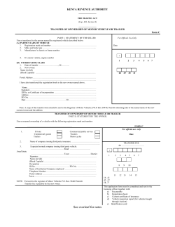


© Copyright 2026