
LEP STA 41 01 Reliability Pack
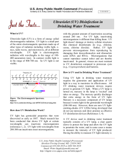
DATA / RELIABILITY
LEP STA 41 01
™
Reliability Pack
October 9, 2014
3542 Basset Street
tel: +1-408-734-1096
Santa Clara, CA 95054 USA
email: info@luxim�com
www�luxim�com
Contents
LEP System Glossary ���������������������������������������������������������������������������������������������������������������������������������������������������������������������������������������������������3
How LEP Technology Works ������������������������������������������������������������������������������������������������������������������������������������������������������������������������������������4
Bulb Thermodynamics and Lifetime Considerations���������������������������������������������������������������������������������������������������������������������������������������5
Environmental Condition������������������������������������������������������������������������������������������������������������������������������������������������������������������������������������������6
DVT/HALT Summary ���������������������������������������������������������������������������������������������������������������������������������������������������������������������������������������������������7
Lumens/CCT Versus Orientation������������������������������������������������������������������������������������������������������������������������������������������������������������������������������9
Lumens/CCT Versus Power ������������������������������������������������������������������������������������������������������������������������������������������������������������������������������������ 10
Lumens/CCT Versus Temperature������������������������������������������������������������������������������������������������������������������������������������������������������������������������ 11
Electrical Profile Ignition and Warm-Up ������������������������������������������������������������������������������������������������������������������������������������������������������������ 12
Start Time Versus Temperature������������������������������������������������������������������������������������������������������������������������������������������������������������������������������ 13
MTBF Summary ��������������������������������������������������������������������������������������������������������������������������������������������������������������������������������������������������������� 14
MTBF Study Details��������������������������������������������������������������������������������������������������������������������������������������������������������������������������������������������������� 15
Accelerated Testing��������������������������������������������������������������������������������������������������������������������������������������������������������������������������������������������������� 16
Notes on Lumens Maintenance and CCT Change������������������������������������������������������������������������������������������������������������������������������������������ 17
Lumen Maintenance������������������������������������������������������������������������������������������������������������������������������������������������������������������������������������������������ 18
CCT Change ���������������������������������������������������������������������������������������������������������������������������������������������������������������������������������������������������������������� 19
Field Trial Data������������������������������������������������������������������������������������������������������������������������������������������������������������������������������������������������������������ 20
UV and IR Performance ������������������������������������������������������������������������������������������������������������������������������������������������������������������������������������������� 21
Compliance & Performance Testing��������������������������������������������������������������������������������������������������������������������������������������������������������������������� 22
LEP System Glossary
Ceramic Resonator
Lamp
Emitter Assembly
Mechanical assembly containing a ceramic resonator and a quartz lamp. Ceramic
resonator channels the RF (radio-frequency) energy into the lamp resulting in a
powerful light emitting plasma. The lamp contains halides needed to generate
the plasma.
RF Driver
Power amplifier (PA) assembly that uses an LDMOS
device to convert electrical energy into RF power. The
PA is designed for ruggedness and efficiency. The
RF driver also contains controls circuit for digital and
Emitter
Assembly
analog lighting controls.
LEP System
RF Driver
System consisting of an emitter assembly and RF driver
connected by an RF cable.
Power Supply
Component that converts AC power into DC power. LEP
system requires a 28 volt DC input.
Fixture
The end lighting system that contains the LEP system,
light shaping components, power supply, and heat
sinks.
Power
Supply
APPLICATION / BRIEF
How LEP Technology Works
LEP light sources create a light-emitting plasma by coupling RF (radio-frequency) energy into an electrode-less quartz lamp.
The RF energy is created and amplified by an RF circuit that is driven by a Solid-State Power Amplifier. The following three
steps outline the process of light generation in all LEP systems:
Lamp
Resonant
Cavity or
“Puck”
Step 1:
Input
An RF circuit is established by connecting an RF power
Probe
amplifier to a ceramic resonant cavity known as the “puck”.
In the center of the puck is a sealed quartz lamp that
contains materials consistent with metal-halide lamps.
Feedback
Probe
Power Amplifier
Step 2:
The puck, driven by the power amplifier, creates a standing wave confined
within its walls. The electric field is strongest at the center of the lamp which
ionizes the gasses inside the lamp (purple glow).
Step 3:
The ionized gas in turn heats up and evaporates the metal-halide
materials which form a bright plasma column within the lamp (blue to
bright white light). This plasma column is centered within the quartz
envelope and radiates light very efficiently. In the back side of the lamp,
a highly reflective powder is used to reflect nearly all of this light in the
forward direction.
Bulb Thermodynamics and Lifetime
Considerations
The LEP emitter design aims to maintain an optimal thermodynamic power balance that enables the highest
plasma output while keeping the lamp wall under a safe operating temperature. The total RF power into
the emitter, P in, is balanced with the radiated optical power, P radiated, and conducted heat by the puck, P
conducted. The lamp chemistry or fill and the geometry are the main parameters used to optimize luminous
flux while keeping the lamp wall temperature below 1100 Kelvin or 827 Celsius. A halide pool gathers at
the coldest spot of the lamp replenishing the plasma through a reversible phase change process during its
entire lifetime.
At the designed vapor pressures and quartz temperatures, devitrification and wall whitening processes
are rare resulting in a long-lasting lamp. A properly designed lamp operating at its specified environment
eliminates catastrophic lamp failures. It should be noted that the LEP lamp does not contain metal
electrodes as a typical HID lamp. Electrodes are the primary cause of failure in such systems where electrode
wear-out, wall darkening from sputtered electrodes, and cracking of quartz-metal seal are common. LEP
emitters do not display any of these failure modes. It is also worth noting that a significant amount of
energy (>20%) in HID lamps are wasted in heating electrodes where this energy is used to create light in a
LEP system. Therefore, the LEP emitter is inherently much more robust and efficient compared to traditional
HID lamp systems.
P radiated
<1100 Kelvin
6000 K
P conducted
P in
Halide pool
(cold spot)
At steady state, the gases (Ar, Hg, metal halides)
are in local thermodynamic equilibrium.
Environmental Condition
The lamp performance is stated for the following environmental conditions:
MIN
MAX
UNITS
Operating Temperature
-40
45
Celsius
Storage Temperature
-40
100
Celsius
Humidity
5% to 95% RH,
Non Condensing
Operating Altitude
12,000
Feet
Transportation Altitude
36,000
Feet
• At ambient temperatures higher than 45 C, the driver temperature can exceed its
recommended limits which will impact its long term reliability. In order to operate for long
periods of time at elevated ambient temperatures, the LEP driver must be heat sunk more
thoroughly and its base temperature validated at the elevated temperatures. The RF cable
is rated for up to 105 C temperature surrounding and therefore should not exceed this limit
if operating in higher ambient temperatures.
• At ambient temperatures lower than -40 C, start time becomes longer and can exceed the
specification for the system. Though there is no specific impact on lifetime or reliability
at cold temperatures, the lamp may experience difficulty in igniting or warming up to full
brightness in the allotted time. See page 13 for the impact of ambient temperature on
start up times.
• The bare LEP system outside of a light fixture is not IP rated. The fixture should be
designed such that water and moisture are kept out of the lamp area as much as possible.
Standard sealing principles for outdoor fixtures apply to LEP fixtures. Please refer to the
LEP Fixture Design Guide for further information.
DVT/HALT Summary
The following Design Verification Test (DVT) of LEP STA-40 lamps was performed in accordance
with mil and ETSI (telecommunications) standards for outdoor products to simulate extreme
environmental and mechanical conditions. The tests, unless otherwise stated, were done to the
bare lamp system and not in a light fixture. Some of the indicated testing were performed in a
mock up fixture that prevents direct moisture from forming on the lamp.
The lamps also were subjected to Highly Accelerated Life Testing (HALT) by
increasing stress levels to induce failures in order to identify the weak points in the
design. The lamp systems were subjected to increasing temperature, vibration,
and power stresses while operating. The reported values are the limits where the
lamp operated without any damage.
Non-Operational
TEST
CONDITIONS
CYCLES
RESULTS
Temperature Cycling
-40º C to +70º C
30 min. intervals – x10
No Failures
Constant Temperature*
w/ Humidity
+70º C @ 90% RH
3 days
No Failures
Random Vibration
10 Hz @ 0.015 g2 /Hz
60 min./axis
No Failures
40 Hz @ 0.015 g2 /Hz
500 Hz @ 0.00015 g2 /Hz
Overall: 1.04 g (rms)
Moisture Intrusion*
(Temperature Humidity)
+30º C & +60º C
Transverse &
Vertical Axis
12 hr. intervals – x6
No Failures
Operational
TEST
CONDITIONS
CYCLES
RESULTS
Temperature Cycling
-45° C to +60° C
11 hr. intervals – x2
No Failures
Constant Temperature*
w/ Humidity
+40° C @90% RH
4 days
No Failures
Sine Sweep Vibration
5 Hz – 62 Hz @ 5 mm/s
60 min./Axis
No Failures
62 Hz – 200 Hz @ 2 m2/s3
Symmetric (round)
Emitter, thus, X = Y Axis
Total: 2 m2/s3
Random Vibration
5 Hz – 10 Hz @ +12 dB
30 min./Axis
10 Hz – 50 Hz @ 0.02 m2/ s3
Symmetric (round)
Emitter, thus, X = Y Axis
50 Hz – 100 Hz @ -12 dB
Overall: 1.063 m/s2 (rms)
Shock (Bump)
X & Z Axis
Half Sine Wave: 25 g
No Failures
X & Z Axis
6 ms intervals – x1000/Axis
No Failures
Symmetric (round)
Emitter, thus, X = Y Axis
+X – x1000, -X – x1000
+Z – x1000, -Z – x1000
Salt Fog*
+98° F in a Salt Fog of 5%
NaCl (specific gravity: 1.035
& pH of 7.0)
4 days total exposure
No Failures
2 days with one unit
cycling 1 hr. on,
then 30 min. off
Other 2 days, unit off
Highly Accelerated Life Testing
TEST
CONDITIONS
CYCLES
RESULTS
Temperature Extremes w/
Varying DC Voltages
-75° C to +55° C
4 hr. interval total
No Failures
Temperature Extremes*
Cycling
-40° C to +60° C
108 min. intervals – x8
(15° C/min. gradients)
No Failures
Random Vibration*
0.5 g (rms) to 7.0 g (rms)
0.5 g (rms) – 15 min.
5 Hz – 500 Hz/g step
1.0 g (rms) – 30 min.
No
Mechanical
Failures
23V DC to 32V DC @ -75° C,
-20° C & +45° C
1.5 g (rms) – 15 min.
2.0 g (rms) – 15 min.
3.0 g (rms) – 15 min.
5.0 g (rms) – 15 min.
7.0 g (rms) – 5 min.
Temperature Extremes*
Cycling w/ Vibration
Cycling
-40° C to +60° C
2.0 g (rms) to 6.0 g (rms)
5 Hz – 500 Hz/g step
*Testing done in simulated fixture.
13 min. + 20 sec. intervals –
x5 (15° C/min. gradients)
No Failures
Lumens/CCT Versus Orientation
STA-41 lamps are designed for vertical down operation and up to 30° Tilt as illustrated in the following
diagram� In the vertical up orientation from -30° (or +330°) to +30°, the plasma output fluctuates due to the
thermodynamics inside the lamp� Operating in the pointing up configuration is prohibited where the lamp
could exhibit flicker�
UP
Down
30° Max
30°° Max
30° Max
Yes
No
Lumens/CCT Versus Power
The following curves depict the power consumption and color temperature
(CCT) of the STA-41 light source as it dims from 100% to 20%. STA-41 source can be electronically dimmed via digital
controls or by 1-10V analog control.
Light Output (%)
Lumens/CCT Versus Temperature
The following data depicts the variation in light output and CCT change over the entire
ambient operating temperature range from -40° to +45° C. There is a maximum of -3% lumens
penalty at hot temperatures and a +100 kelvin color shift at cold temperatures. The lumens
decrease is a result of RF amplifier inefficiency at hot and the color shift is due to decreased
120%
170
100%
140
80%
110
Light Output Change (%)
60%
80
CCT Change (Delta Kelvins)
40%
50
20%
20
0%
-10
-60
-40
-20
0
Environment Temperature
(Degrees Celcius)
20
40
60
Delta Kelvins
% Lumens Change
lamp cold spot temperature.
Electrical Profile Ignition and
Warm-Up
The following data shows the current profile that the RF driver draws during its
warm up process. It is typical for the RF amplifier to draw as much as 14 amperes
from the DC power source. Therefore, the DC power source must be chosen such
that it does not have a cut off below 14 amperes.
Start Current Profile (V=28 volts)
Start Current Profile (V=28 Volts)
16
16
14
14
Current (Amperes)
12
12
10
10
8
6
4 (Amperes)
Current
Min Range
Max Range
2
0
00
120
120
240
240
360480 480600
360
720
600
(Seconds)
TimeTime
(seconds)
840 960 840 1080 960
720
1080
Start Time Versus Temperature
The following data shows the lamp start time as a function of temperatures.
The lamp start time takes up to 10 seconds longer at cold temperatures of -40º C
compared with room temperature.
25C Start Time
Moments
Target
20
25
30
Mean28.7
35
40
45
Std Dev
4.4
Std Err Mean
0.8
Upper 95% Mean
30.3
Lower 95% Mean
27.1
50
-40C Start Time
Moments
Target
20
25
30
Mean32.1
35
40
45
Std Dev
7.0
Std Err Mean
1.2
Upper 95% Mean
34.7
Lower 95% Mean
29.6
50
+55C Start Time
Moments
Target
20
25
30
Mean27.6
35
40
45
50
Std Dev
3.9
Std Err Mean
0.7
Upper 95% Mean
29.0
Lower 95% Mean
26.2
MTBF Summary
MTBF (mean time before failure) is a basic measure of reliability for repairable
electronic assemblies. It is calculated as T/N where T is the total operating time
and N is the number of catastrophic failures. MTBF calculations do not reflect
parametric failures where electrical or optical output decreases beyond the
specified parameter. In a lighting system, parametric failures are shown by lumen
and CCT maintenance plots (see page 19 Lumen Maintenance).
Catastrophic failure rate over time of the RF driver follows a typical bathtub curve
observed in many electronics assemblies. There are three distinct periods in the
bathtub curve that describes the failure rate over time. First period is characterized
by decreasing failure rate and occurs in early life due to infant mortality. This
period is relatively short and the weaker units die off leaving a population of more
rigorous units. To ensure that the weaker units are not released, LUXIM performs
burn in and power cycling of lamp systems. In addition, LUXIM uses components
that are rated for significantly higher temperature than actual use condition. The
next period characterized by a low but constant failure rate where the failures are
random in nature. This is the period of useful life of the RF driver where MTBF and FIT
calculations apply. The last period is characterized by an increasing failure where
components wear out due to physical, electronic, and thermal stresses over its
lifetime. MTBF calculations are no longer valid in this period.
Failure rate
(failures/unit time)
Burn in
(infant mortality)
Wear-out
Useful life
(random ta: lives)
Lifetime
MTBF Study Details
In the period of useful life, the failure rate, R(t) can be computed as R(t)=e-λt
whereλis =1/MTBF and t is the operating time. The probability of catastrophic failure is
simply P(t) = 1- R(t).
The MTBF calculations for the STA-41 RF driver are performed using MIL-STD-217
techniques. There are several factors that determine reliability including:
»» Temperature of operation
»» Stress levels of the components
»» Time in production (learning curve)
»» Quality level of the components
»» Operating environment
The system MTBF calculation is done using data from actual testing by component
manufacturers and historical performance of the components. The following conditions
were assumed:
»» 85º C base plate temperature
»» Learning curve of < 1 year
»» COTS quality level (commercial off the shelf )
»» Ground, Fixed (not directly exposed to the outer environment)
»» Typical and Maximum stress levels
With these assumptions, the LEP RF Driver has an MTBF of 151,000 hours at maximum stress levels and
212,000 at typical stress levels. This corresponds to a 28% and 21% failure rate at the specified 50,000
hours. In a properly designed light fixture, 79% survival at the end of life is typical.
Learning curve
(years)
Stress level
t (hours)
MTBF
lambda - 1/
MTBF
R(t) = exp[-lambda * t]
P(t)
1
max
50000
150965
6.62E-06
0.72
0.28
1
typical
50000
212000
4.72E-06
0.79
0.21
Accelerated Testing
One method of accelerating the failure mechanism of RF drivers is to power cycle
the lamp system. Power cycling introduces the most stress on the RF electronics
due to unfavorable load conditions, higher current spikes, and rapid thermal
change.
Below is the measured survival rate over time due to rapid cycling of STA-41 series
lamps (10 minutes ON/15 minutes OFF). LEP drivers sustained greater than 8000
power cycles with greater than 90% survival rate. This is equivalent to more than
20 years of operation.
100%
10000
90%
9000
80%
8000
70%
7000
60%
6000
50%
5000
Survival Rate
40%
4000
Number of Starts
30%
3000
20%
2000
10%
1000
0%
0%
0
5
10
15
Equivalent Number of Years
20
25
Number of Starts
Survival Rate
Driver Sustainability Over Time
Lamps Cycling 10 Minutes On / 15 Minutes Off
Notes on Lumens Maintenance
and CCT Change
Lumens and CCT maintenance for the STA-41 lamp is extrapolated from measured data of the
previous generation of emitter design (STA-40). STA-41 lamps are expected to perform similar
or better as they use the same lamp chemistry and have an even lower wall loading (power
input/inner surface are of lamp) and hence lower thermal stress that the STA-40 emitter. The
lifetime of the LEP-STA-41 plasma systems are defined as the time to 70% lumen maintenance
of L70. Below are some notes on the lumen maintenance testing:
1. Lumen maintenance is extrapolated from actual lamp (emitter + driver) data
of 5000 hours. As data is updated every 1000 hours, LUXIM will continue to
update the extrapolation.
2. Seasoning period of first 300 hours is eliminated in order to extrapolate the
lumen maintenance end of life.
3. Lumens are measured in an integrating sphere following closely to IESNA LM79 standard 2π measurement geometry.
4. Test conditions are as follows:
»» 30º C room temperature
»» Constant current and voltage
»» Emitter oriented vertical down
»» Benchmarking at 1000 hour intervals
Lumen Maintenance
Typical Lumen Maintenance Ra=80
Typical STA 41 Lumen Maintenance
100%
90%
80%
% Light Output
70%
60%
50%
Lumens
40%
30%
avg extrapol�
20%
max extrapol�
10%
min extrapol�
0%
0
10000
20000
30000
Hours of Operation
40000
50000
CCT Change
Typical CCT Change Ra=80
8000
7000
CCT (Kelvins)
6000
5000
4000
3000
CCT
(kelvin)
2000
1000
0
0
500
1000
1500
2000
Hours of Operation
2500
3000
3500
Field Trial Data
In order to validate predictions for lumen and CCT maintenance based on life test data
(pages 17 and 18), LUXIM continually monitors field trials. Field trials are the most unbiased
data set that captures degradation in not only the light source but also in the optics,
electronics and thermal management of the fixture.
Below is the measured performance of light fixtures using STA-41-01 light source in outdoor field trials. This
trial consists of 12 cobra head light fixtures on a 12 hour ON/12 hour OFF cycle.
Pictures of the test site
UV and IR Performance
The following data represent the typical spectral emission in W/nm for the STA-41
emitter from 200 nm to 3000 nm. It is overlaid with the sun’s spectrum and with the
human eye’s response to light (photopic curve).
L I F I -S T A - 4 1 -0 2 S p e c t r a l D i s t r i b u t i o n 2 0 0 -3 0 0 0 n m
00.4
.4
1
STA-41-02
(W/nm)
STA-41-02 (W/nm)
Sunlight (normalized)
Sunlight
(normalized)
0.322
0 .3
00.8.8
Photopic (normalized)
Photopic
(normalized)
00.6.6
W/nm
0.166
0 .1
00.4.4
0.088
0 .0
00.2.2
W/nm
0.244
0 .2
00
0
2 200
00
700
70 0
11200
20 0
11700
700
22200
2 0 0 2700 2 7 0 0
W a v Wavelength
e l e n g t h(nm)
(n m )
Watts
Percentage
UV (200-400)
10.9
9%
Visible (400-750)
85.6
70%
NIR (750-1400)
20.7
17%
SWIR (1400-3000)
5.4
4%
Compliance & Performance
Testing
STA-41 lamps and luminaries will be subjected to the following regulatory and
standardized testing.
Photometric and Flux Measurement: LTL Test Report, Number 21950
Safety Light Source: UL1029 (US), EN 61347-1: 2008, EN 61347-2-9: 2001 (EU)
EMC: FCC Part 18 Class A, CISPR22, EN55022
Recycling and Waste: RoHS, WEEE (EU)


© Copyright 2026